Embed Size (px)
Citation preview
Shear Stress-Slip Model for Steel-CFRP Single-Lap Joints under
Thermal Loading
*Ankit Agarwal1), Ehab Hamed2) and Stephen J Foster3)
1), 2), 3) Centre for Infrastructure Engineering and Safety, School of Civil and
Environmental Engineering, The University of New South Wales Sydney, UNSW Sydney, Australia
ABSTRACT
The shear stress-slip model (SSM) has been intensively used in the past for different kind of adhesive joints and with various stress-slip relations. However in those studies, the flexural stiffness of the adherends was neglected. In this paper, both the adherends (steel and CFRP) in a single-lap joint are modelled as linear elastic Bernoulli-Euler beams with axial and flexural stiffness, while the adhesive layer and its interfaces are modelled as an artificial interface that is governed by a linear relation between the slip and the interfacial shear stress. Two types of thermal loading, namely freeze-thaw cycling and thermal cycling, are investigated, whose effects are introduced in terms of reduced elastic modulus of the adhesive. Engineering shear strain based failure criterion is then used to predict the failure load. The predicted strengths of the joints are compared with experimental results and are found to be in good agreement. Parametric studies were then conducted to investigate the influence of adhesive thickness. 1. INTRODUCTION The behavior of adhesive joints have been intensively investigated in recent years using both finite element modelling and analytical modelling approaches (Chiew et al. 2011; Yu et al. 2011; Yu et al. 2012; da Silva et al. 2009; da Silva et al. 2009; Mancusi and Ascione 2013). However, there is no theoretical model in the literature capable of predicting the failure load including the effects of freeze-thaw (F-T) cycles and thermal cycles. The applications of these cycles have significant influence on the bond strength of steel-CFRP single-lap joint (Agarwal et al. 2014 and 2015).
1)
Research Associate; 2)
Senior Lecturer; 3)
Professor and Head of School
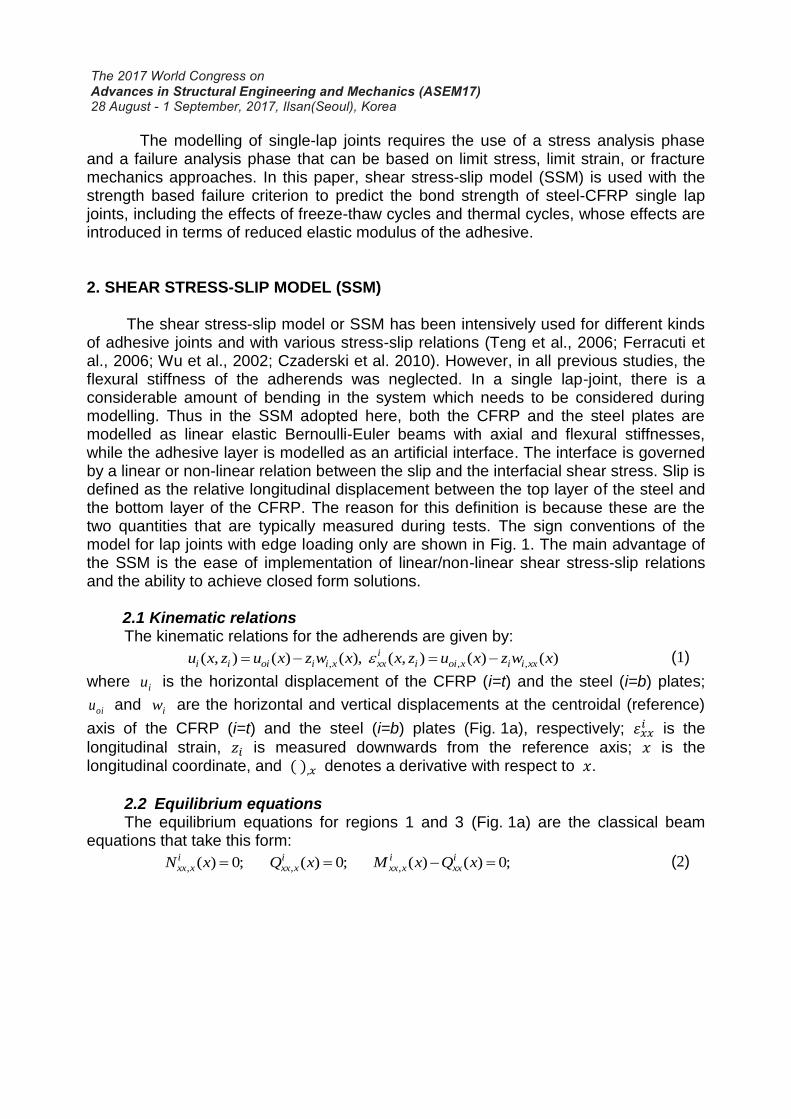
The modelling of single-lap joints requires the use of a stress analysis phase and a failure analysis phase that can be based on limit stress, limit strain, or fracture mechanics approaches. In this paper, shear stress-slip model (SSM) is used with the strength based failure criterion to predict the bond strength of steel-CFRP single lap joints, including the effects of freeze-thaw cycles and thermal cycles, whose effects are introduced in terms of reduced elastic modulus of the adhesive. 2. SHEAR STRESS-SLIP MODEL (SSM) The shear stress-slip model or SSM has been intensively used for different kinds of adhesive joints and with various stress-slip relations (Teng et al., 2006; Ferracuti et al., 2006; Wu et al., 2002; Czaderski et al. 2010). However, in all previous studies, the flexural stiffness of the adherends was neglected. In a single lap-joint, there is a considerable amount of bending in the system which needs to be considered during modelling. Thus in the SSM adopted here, both the CFRP and the steel plates are modelled as linear elastic Bernoulli-Euler beams with axial and flexural stiffnesses, while the adhesive layer is modelled as an artificial interface. The interface is governed by a linear or non-linear relation between the slip and the interfacial shear stress. Slip is defined as the relative longitudinal displacement between the top layer of the steel and the bottom layer of the CFRP. The reason for this definition is because these are the two quantities that are typically measured during tests. The sign conventions of the model for lap joints with edge loading only are shown in Fig. 1. The main advantage of the SSM is the ease of implementation of linear/non-linear shear stress-slip relations and the ability to achieve closed form solutions. 2.1 Kinematic relations
The kinematic relations for the adherends are given by:
, , ,( , ) ( ) ( ), ( , ) ( ) ( )i
i i oi i i x xx i oi x i i xxu x z u x z w x x z u x z w x (1)
where iu is the horizontal displacement of the CFRP (i=t) and the steel (i=b) plates;
oiu and iw are the horizontal and vertical displacements at the centroidal (reference)
axis of the CFRP (i=t) and the steel (i=b) plates (Fig. 1a), respectively; 𝜀𝑥𝑥𝑖 is the
longitudinal strain, 𝑧𝑖 is measured downwards from the reference axis; 𝑥 is the longitudinal coordinate, and ( ),𝑥 denotes a derivative with respect to 𝑥.
2.2 Equilibrium equations The equilibrium equations for regions 1 and 3 (Fig. 1a) are the classical beam equations that take this form:
, , ,( ) 0; ( ) 0; ( ) ( ) 0;i i i ixx x xx x xx x xxN x Q x M x Q x (2)
Fig. 1: Shear stress-slip model: a) Sign convention; and b) internal resultants.
For Region 2, the equilibrium equations account for the interfacial shear stresses
as follows:
, ,( ) ( ) 0; ( ) ( ) 0;t bxx x xx xN x x b N x x b (3)
, ,( ) 0; ( ) 0;t bxx x xx xQ x Q x (4)
, ,( ) ( ) ( ) 0; ( ) ( ) ( ) 0;2 2
t t b bt bxx xx x xx xx x
bd bdQ x M x x Q x M x x (5)
where ixxN , i
xxM , and ixxQ are the axial force, bending moment, and shear force,
respectively; b is the width of the lap joint; 𝜏 is the interfacial shear stress; dt and db are the thickness of the top adherend (CFRP) and the bottom adherend (steel), respectively. For simplicity, it is assumed that the shear stress-slip relation can be approximated as linear before debonding and that the shear stress immediately drops
x
zb,wb
Region 1 Region 3Region 2
uob
uot
zt,wtSteel
CFRP N
Q
M
dx
Nxxt
Mxx
t
Nxx +Nxx,x dxt t
Qxxt
Mxx +Mxx,xdxt t
Qxx +Qxx,xdxt t
b dxx)
Mxx
b
Nxxb
Qxxb
Mxx +Mxx,xdxb b
Nxx +Nxx,x dxb b
Qxx +Qxx,xdxb b
a)
b)
L
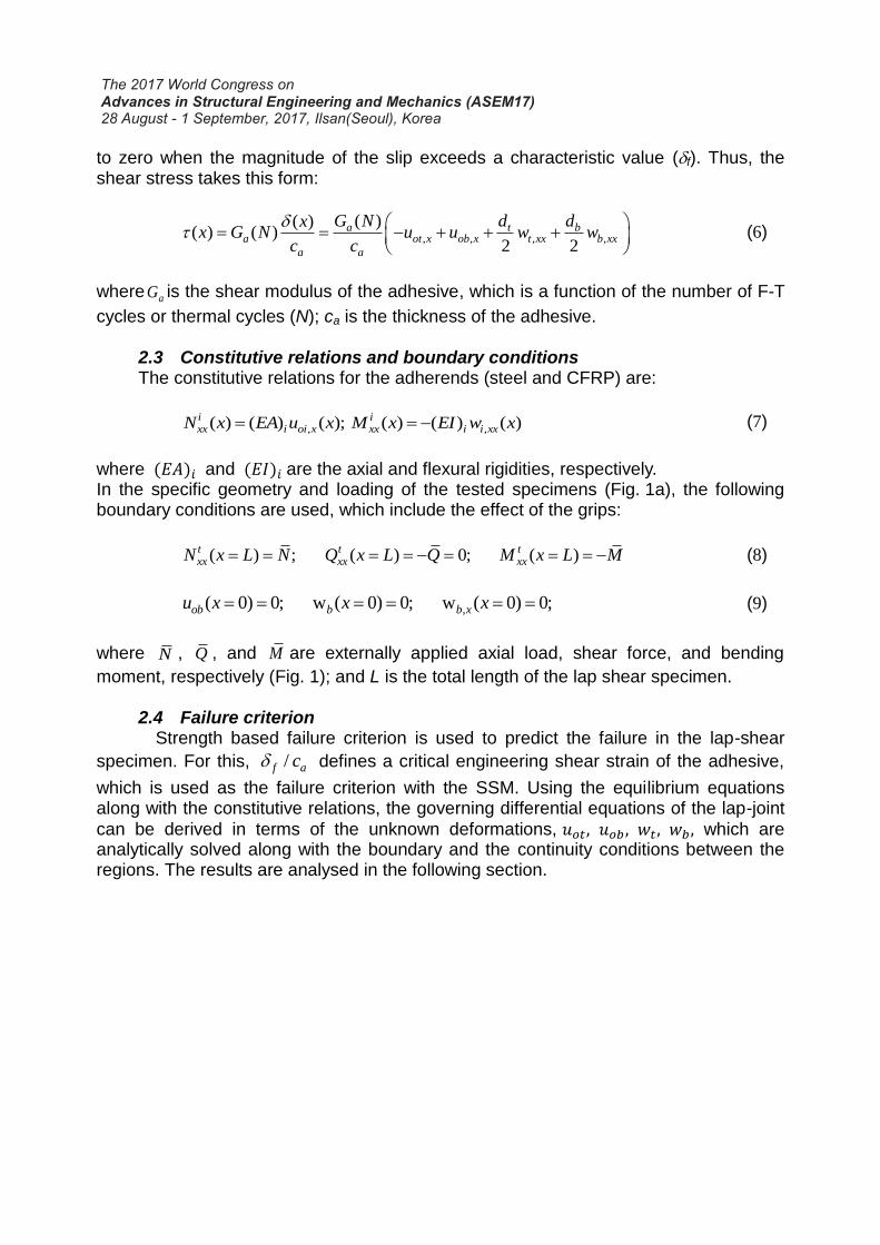
to zero when the magnitude of the slip exceeds a characteristic value (f). Thus, the shear stress takes this form:
, , , ,
( )( )( ) ( )
2 2
a t ba ot x ob x t xx b xx
a a
G N d dxx G N u u w w
c c
(6)
where aG is the shear modulus of the adhesive, which is a function of the number of F-T
cycles or thermal cycles (N); ca is the thickness of the adhesive.
2.3 Constitutive relations and boundary conditions The constitutive relations for the adherends (steel and CFRP) are:
, ,( ) ( ) ( ); ( ) ( ) ( )i ixx i oi x xx i i xxN x EA u x M x EI w x (7)
where (𝐸𝐴)𝑖 and (𝐸𝐼)𝑖 are the axial and flexural rigidities, respectively. In the specific geometry and loading of the tested specimens (Fig. 1a), the following boundary conditions are used, which include the effect of the grips:
( ) ; ( ) 0; ( )t t txx xx xxN x L N Q x L Q M x L M (8)
,( 0) 0; w ( 0) 0; w ( 0) 0;ob b b xu x x x (9)
where N , Q , and M are externally applied axial load, shear force, and bending
moment, respectively (Fig. 1); and L is the total length of the lap shear specimen. 2.4 Failure criterion
Strength based failure criterion is used to predict the failure in the lap-shear
specimen. For this, /f ac defines a critical engineering shear strain of the adhesive,
which is used as the failure criterion with the SSM. Using the equilibrium equations along with the constitutive relations, the governing differential equations of the lap-joint
can be derived in terms of the unknown deformations, 𝑢𝑜𝑡, 𝑢𝑜𝑏 , 𝑤𝑡, 𝑤𝑏 , which are analytically solved along with the boundary and the continuity conditions between the regions. The results are analysed in the following section.
3. NUMERICAL STUDY
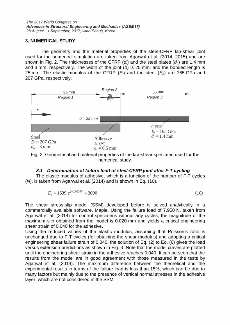
The geometry and the material properties of the steel-CFRP lap-shear joint used for the numerical simulation are taken from Agarwal et al. (2014, 2015) and are shown in Fig. 2. The thicknesses of the CFRP (dt) and the steel plates (db) are 1.4 mm and 3 mm, respectively. The width of the joint (b) is 25 mm, and the bonded length is 25 mm. The elastic modulus of the CFRP (Et) and the steel (Eb) are 165 GPa and 207 GPa, respectively.
Fig. 2: Geometrical and material properties of the lap-shear specimen used for the
numerical study.
3.1 Determination of failure load of steel-CFRP joint after F-T cycling The elastic modulus of adhesive, which is a function of the number of F-T cycles
(N), is taken from Agarwal et al. (2014) and is shown in Eq. (10).
( 0.055 )1639 3000NaE e (10)
The shear stress-slip model (SSM) developed before is solved analytically in a commercially available software, Maple. Using the failure load of 7,950 N, taken from Agarwal et al. (2014) for control specimens without any cycles, the magnitude of the maximum slip obtained from the model is 0.020 mm and yields a critical engineering shear strain of 0.040 for the adhesive. Using the reduced values of the elastic modulus, assuming that Poisson’s ratio is unchanged due to F-T cycles (for obtaining the shear modulus) and adopting a critical engineering shear failure strain of 0.040, the solution of Eq. (2) to Eq. (6) gives the load versus extension predictions as shown in Fig. 3. Note that the model curves are plotted until the engineering shear strain in the adhesive reaches 0.040. It can be seen that the results from the model are in good agreement with those measured in the tests by Agarwal et al. (2014). The maximum difference between the theoretical and the experimental results in terms of the failure load is less than 15%, which can be due to many factors but mainly due to the presence of vertical normal stresses in the adhesive layer, which are not considered in the SSM.
x
Region 1 Region 3 85
25 85
Steel E b = 207 GPa d b = 3 mm
Region 2
CFRP E t = 165 GPa d t = 1.4 mm
Adhesive E a ( N ) c a = 0.5 mm
b = 25 mm
mm mm
mm
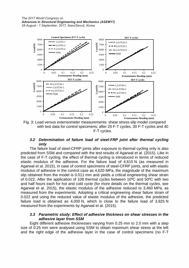
Fig. 3: Load versus extensometer measurements: shear stress-slip model compared
with test data for control specimens; after 20 F-T cycles, 30 F-T cycles and 40 F-T cycles.
3.2 Determination of failure load of steel-FRP joint after thermal cycling
only The failure load of steel-CFRP joints after exposure to thermal cycling only is also
predicted from SSM and compared with the test results of Agarwal et al. (2015). Like in the case of F-T cycling, the effect of thermal cycling is introduced in terms of reduced elastic modulus of the adhesive. For the failure load of 4,610 N (as measured in Agarwal et al. 2015), in case of control specimens of steel-CFRP joints, and with elastic modulus of adhesive in the control case as 4,620 MPa, the magnitude of the maximum slip obtained from the model is 0.011 mm and yields a critical engineering shear strain of 0.022. After the application of 108 thermal cycles between 10ºC and 50ºC with two and half hours each for hot and cold cycle (for more details on the thermal cycles, see Agarwal et al. 2015), the elastic modulus of the adhesive reduced to 3,460 MPa, as measured from the experiments. Adopting a critical engineering shear failure strain of 0.022 and using the reduced value of elastic modulus of the adhesive, the predicted failure load is obtained as 4,000 N, which is close to the failure load of 3,925 N measured from the experiments by Agarwal et al. (2015).
3.3 Parametric study: Effect of adhesive thickness on shear stresses in the
adhesive layer from SSM Eight different adhesive thicknesses varying from 0.25 mm to 2.0 mm with a step
size of 0.25 mm were analysed using SSM to obtain maximum shear stress at the left and the right edge of the adhesive layer in the case of control specimens (no F-T
0
1500
3000
4500
6000
7500
9000
0 0.05 0.1 0.15 0.2 0.25
Lo
ad
(N
)
Extensometer Reading (mm)
20 F-T cycles
LS-FT20-4
LS-FT20-5
LS-FT20-6
SSM
0
1500
3000
4500
6000
7500
9000
0 0.05 0.1 0.15 0.2 0.25
Lo
ad
(N
)
Extensometer Reading (mm)
30 F-T cycles
LS-FT30-1
LS-FT30-3
LS-FT30-5
SSM
0
1500
3000
4500
6000
7500
9000
0 0.05 0.1 0.15 0.2 0.25
Lo
ad
(N
)
Extensometer Reading (mm)
40 F-T cycles
LS-FT40-1
LS-FT40-2
LS-FT40-3
SSM
0
1500
3000
4500
6000
7500
9000
0 0.05 0.1 0.15 0.2 0.25
Lo
ad
(N
)
Extensometer Reading (mm)
Control Specimens (0 F-T cycle)
LS-FT0-1
LS-FT0-3
LS-FT0-4
SSM
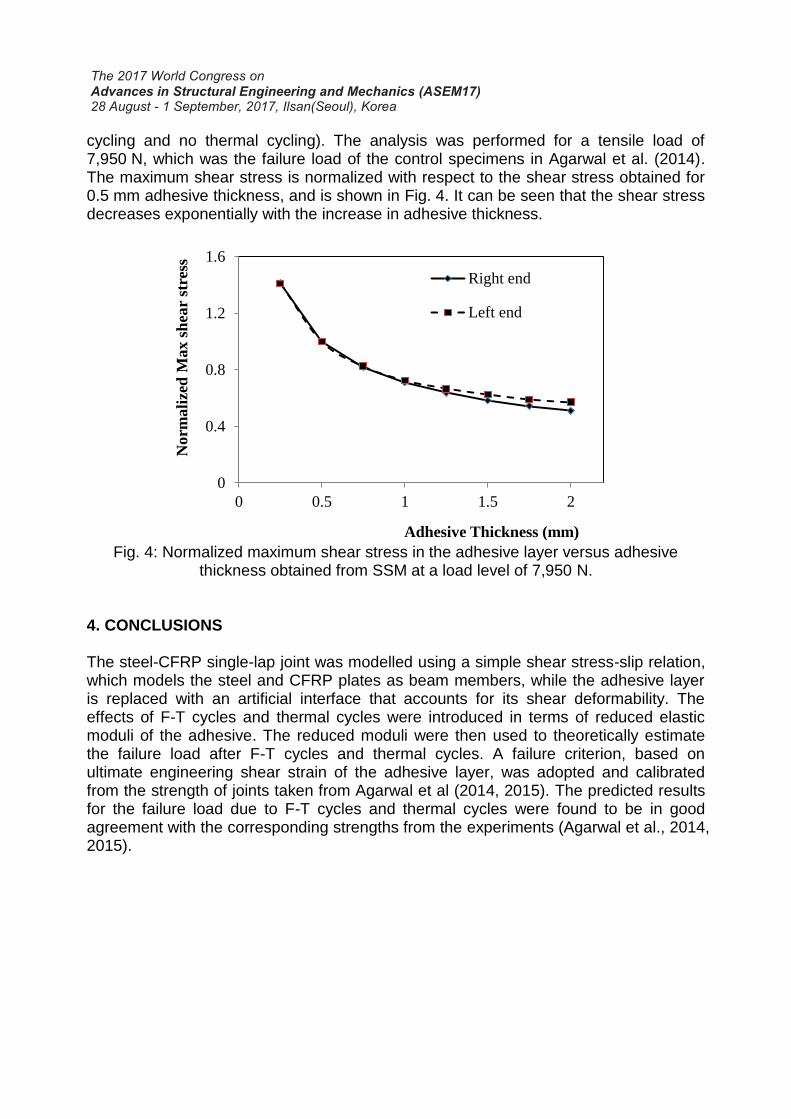
cycling and no thermal cycling). The analysis was performed for a tensile load of 7,950 N, which was the failure load of the control specimens in Agarwal et al. (2014). The maximum shear stress is normalized with respect to the shear stress obtained for 0.5 mm adhesive thickness, and is shown in Fig. 4. It can be seen that the shear stress decreases exponentially with the increase in adhesive thickness.
Fig. 4: Normalized maximum shear stress in the adhesive layer versus adhesive
thickness obtained from SSM at a load level of 7,950 N.
4. CONCLUSIONS The steel-CFRP single-lap joint was modelled using a simple shear stress-slip relation, which models the steel and CFRP plates as beam members, while the adhesive layer is replaced with an artificial interface that accounts for its shear deformability. The effects of F-T cycles and thermal cycles were introduced in terms of reduced elastic moduli of the adhesive. The reduced moduli were then used to theoretically estimate the failure load after F-T cycles and thermal cycles. A failure criterion, based on ultimate engineering shear strain of the adhesive layer, was adopted and calibrated from the strength of joints taken from Agarwal et al (2014, 2015). The predicted results for the failure load due to F-T cycles and thermal cycles were found to be in good agreement with the corresponding strengths from the experiments (Agarwal et al., 2014, 2015).
0
0.4
0.8
1.2
1.6
0 0.5 1 1.5 2
Norm
ali
zed
Max s
hea
r st
ress
Adhesive Thickness (mm)
Right end
Left end
REFERENCES Agarwal, A., Foster, S. J., & Hamed, E. (2015). “Wet thermo-mechanical behavior of
steel–CFRP joints–An experimental study”. Composites Part B: Engineering, 83, 284-296.
Agarwal, A., Foster, S. J., Hamed, E., & Ng, T. S. (2014). “Influence of freeze–thaw cycling on the bond strength of steel–FRP lap joints”. Composites Part B: Engineering, 60, 178-185.
Chiew, S.P., Yu, Y. and Lee, C.K. (2011). “Bond failure of steel beams strengthened with FRP laminates - Part 1: Model development”, Composites Part B: Engineering, 42(5), 1114-21.
Czaderski, C. and Rabinovitch, O. (2010). “Structural Behaviour and inter-layer displacements in CFRP plated steel beams - Optical measurements, analysis, and comparative verification”, Compos Part B: Eng, 40, 276-86.
daSilva, L.F.M., Neves, P.J.C., Adams, R.D. and Spelt, J.K. (2009). “Analytical models of adhesively bonded joints - Part I: Literature Survey”, International Journal of Adhesion & Adhesives, 29, 319-30.
daSilva, L.F.M., Neves, P.J.C., Adams, R.D., Wang, A. and Spelt, J.K. (2009). “Analytical models of adhesively bonded joints - Part II: Comparative study”, International Journal of Adhesion & Adhesives. 29, 331-41.
Ferracuti, B., Savoia, A. and Mazzotti, C. (2006). “A numerical model for FRP-concrete delamination”, Compos Part B: Eng, 37(4-5), 356-64.
Mancusi, G. and Ascione, F. (2013). “Performance at collapse of adhesive bonding”, Composite Structures, 96, 256-61.
Teng, J.G., Yuan, H. and Chen, J. (2006). “FRP-to-Concrete interfaces between two adjacent cracks: theoretical model for debonding failure”, Int J Solids Struct, 43(18-19), 5750-78.
Wu, Z., Yuan, H. and Niu, H. (2002). “Stress transfer and fracture propagation in different kinds of adhesive joints”, J Eng Mech, ASCE, 128(5), 562-73.
Yu, T., Fernando, D., Teng, J.G. and Zhao, X.L. (2012). “Experimental study on CFRP-to-steel bonded interfaces”, Composites Part B: Engineering, 43(5), 2279-89.
Yu, Y., Chiew, S.P. and Lee, C.K. (2011). “Bond failure of steel beams strengthened with FRP laminates – Part 2: Verification”, Composites Part B: Engineering, 42(5), 1122-34.