Embed Size (px)
Citation preview


- 1 -
Altair would like to acknowledge the SMDI Lightweight Wheel Project Team for their valuable assistance in spearheading this study and guiding it to a successful conclusion:
NAME COMPANY
CHAIRPERSON J. Stachowski Nucor Steel MEMBERS M. Bagley Ford Motor Company W. Bernert ArcelorMittal USA A. Bhagwan ThyssenKrupp Steel USA, LLC L. Carbaugh Topy America, Inc. B. Clauw General Motors Company D. Clawson Accuride Corporation M. Csapo Hayes-Lemmerz International T. Darden United States Steel Corp. B. A. DePompolo United States Steel Corp. M. Eshler General Motors Company T. Fletcher Maxion Wheels R. Goetz Carlisle Tire & Wheel Corp. T. Heck Hayes-Lemmerz International R. Huszarik Chrysler Group LLC P. Jones Topy America, Inc. P. Liebold Chrysler Group LLC B. Lutt Lacks Wheel Trim Systems D. G. McFarland Heidtman Steel Products T. Mioduszewski Accuride Corporation D. Rubin Maxion Wheels M. A. Varda Hess Industries, Inc G. VanGuilder CMWA Steel Division E. Waelchli IBD Connections, Inc K. Wardynski Lacks Wheel Trim Systems B. Wilkinson ThyssenKrupp Steel USA, LLC J. Zubkus Lacks Wheel Trim Systems CONSULTANTS A. Guilloteau Altair ProductDesign J. Helner Altair ProductDesign T. Smith Altair ProductDesign
STAFF D. W. Anderson SMDI M. S. Bzdok SMDI J. Greenfelder SMDI R. P. Krupitzer SMDI D. S. Lorincz SMDI

- 2 -
Table of Contents
1 Executive Summary ................................................................................................................................. - 4 -
2 Project Introduction ............................................................................................................................. - 5 -
3 Technology Review .............................................................................................................................. - 5 -
3.1 Materials ................................................................................................................................................ - 6 -
3.2 Manufacturing ...................................................................................................................................... - 6 -
3.3 Design Architecture ............................................................................................................................. - 6 -
3.3.1 Topology Optimization .............................................................................................................................................................. - 6 - 3.3.2 Gauge and Shape Optimization ................................................................................................................................................ - 7 -
4 Wheel Target Study ............................................................................................................................. - 7 -
5 Design Methodology ........................................................................................................................... - 8 -
6 Lightweight Steel Wheel Development ........................................................................................... - 10 -
6.1 Package Space Envelope Generation ............................................................................................... - 10 -
6.2 Topology Optimization (Structural Load Path Development and Aesthetic Inspiration) ....... - 12 -
6.2.1 Model Setup................................................................................................................................................................................ - 12 - 6.2.2 Optimization Parameters (driving Manufacturing and Aesthetic Design options) ....................................................... - 14 -
7 Interpretation and Preliminary Concepts ....................................................................................... - 17 -
8 Proposed Designs ............................................................................................................................... - 21 -
8.1 Malibu Wheel ...................................................................................................................................... - 21 -
8.2 Stiffness comparison .......................................................................................................................... - 21 -
8.3 Gauge Optimization .......................................................................................................................... - 22 -
8.4 Concept Selection ............................................................................................................................... - 23 -
8.5 Strength Study .................................................................................................................................... - 24 -
8.6 Formability Study............................................................................................................................... - 26 -
9 Cost Study ........................................................................................................................................... - 27 -
10 Final Concept Selection ..................................................................................................................... - 28 -
11 Aesthetic Design Flexibility .............................................................................................................. - 28 -
12 Conclusions ......................................................................................................................................... - 29 -

- 3 -
Table of Figures Figure 1: Objectives ........................................................................................................................................ - 8 - Figure 2: Generic Illustration of Design Process ........................................................................................ - 9 - Figure 3: Environment – 2D drawing ........................................................................................................ - 10 - Figure 4: Package Space – 3D envelope (half shown) .............................................................................. - 11 - Figure 5: Overlay of Package Space Envelope and Malibu Steel Wheel ............................................... - 11 - Figure 6: Envelope Mesh ............................................................................................................................. - 12 - Figure 7: Loading Conditions ..................................................................................................................... - 13 - Figure 8: Preliminary Topology Results .................................................................................................... - 14 - Figure 9: Comparison between Draw Direction Definitions .................................................................. - 14 - Figure 10: Comparison between Number of Patterns (No Draw Constraints) .................................... - 15 - Figure 11: Comparison between Number of Patterns (Single Draw Direction) .................................. - 16 - Figure 12: Comparison between Number of Patterns (Reverse Draw Direction) ............................... - 16 - Figure 13: Comparison between Number of Patterns (Split Draw Direction) ..................................... - 17 - Figure 14: Two examples from overlay study of 3 & 5 Spoke wheels ................................................... - 17 - Figure 15: Malibu Steel Wheel .................................................................................................................... - 18 - Figure 16: “Drop Well” Concepts ............................................................................................................... - 19 - Figure 17: “Bead Face” Concepts – Joint between Spokes and Rim ...................................................... - 19 - Figure 18: Concept 1 ..................................................................................................................................... - 20 - Figure 19: Concept 2 ..................................................................................................................................... - 20 - Figure 20: Stiffness Comparison ................................................................................................................. - 21 - Figure 21: Concept 1 – Gauge optimization .............................................................................................. - 22 - Figure 22: Concept 2 – Gauge optimization .............................................................................................. - 23 - Figure 23: Stress Levels Comparison – Radial Load Case....................................................................... - 24 - Figure 24: Stress Levels Comparison – Lateral Load Case ...................................................................... - 25 - Figure 25: Stress Levels Comparison – Bending Load Case ................................................................... - 25 - Figure 26: Formability Material Properties ............................................................................................... - 26 - Figure 27: Comparison of Thinning Contours .......................................................................................... - 26 - Figure 28: Comparison of Formability Contours ..................................................................................... - 27 - Figure 29: Lightweight Wheel Concept ..................................................................................................... - 28 - Figure 30: Wheel Dress Ideas ...................................................................................................................... - 29 -
- 4 -
1 Executive Summary
Current automotive wheels utilize materials and processes that have been in use for many years. Hard lines are typically drawn around lightweight wheels being expensive and lower cost wheels limiting in terms of aesthetic freedom. It is clear that there is an opportunity for the steel wheel to increase market penetration within the automotive sector by focusing on a stylish, lightweight and low cost alternative.
In commissioning this project, the SMDI set forth an overall goal to develop a generic wheel design with the equivalent style, structural performance and mass, along with a 30% cost reduction, of a cast aluminum baseline wheel. Additionally, it was desired that the lightweight steel wheel architecture, although highly styled in its baseline form, would provide a means to be readily upgraded with additional wheel trim (i.e. trim rings, hub caps, accent strips and a full wheel cover). This would enhance the flexibility of the base wheel by providing industrial designers with a larger pallet of options in which to differentiate the wheels for a specific application.
The overall process applied included: • Topology/topography optimization that provided:
o Design inspiration for aesthetic shapes and spoke patterns o Definition of the optimal wheel construction from a choice of full face, bead seat and
drop well wheel o Definition of the optimal load path shape for the chosen number of spokes
• Gauge and shape optimization to refine the wheel geometry to maximize performance while minimizing mass
• Consideration of a wide range of materials including advanced high strength steels • Final material selection of SAE J2340 490Y grade steel for both rim and disc • Ideation and depiction of alternative accessory wheel trim and dress items options
The results of this process: • A design that can replace the GMC Terrain aluminum cast wheel (the design surrogate)
without assembly and packaging issues • Equivalent mass and performance to the baseline cast aluminum wheel with a 30% cost
reduction. • A high style, baseline wheel with an upgrade path to additional aesthetic differentiation
through application of alternate trim options • A guideline for engineers to develop lightweight wheel structures

- 5 -
Figure A: Lightweight Steel Wheel Concept
The Lightweight Steel Wheel Concept, at this stage in the design development process, shows promise as a means to develop lower cost, high style, steel wheel solutions with equivalent mass to typical cast aluminum wheel solutions. It is an excellent foundation for a Phase II design investigation. Phase II will be a necessary next step to evaluate vehicle level performance, via a prototype build and physical testing.
2 Project Introduction
This project involved applying state-of–the-art concept design and analytical methods to an existing high volume wheel to achieve an advanced lightweight design that can be adapted, in concept, to other vehicle platforms across this industry class. Advanced manufacturing processes and new steel materials were also evaluated to increase the weight and cost savings potential for the wheel assembly design. The results of this study demonstrate a lightweight design methodology in a format that can be used by wheel designers in OEM’s and suppliers throughout the North America to improve their designs and significantly reduce the weight and cost of the wheels. Newly introduced tools in the field of concept design development include combining a complete packaging study with the analytical methods of topology optimization to formulate concept architectures for efficient structures. This approach leads the designer to consider the most effective load paths for the design, not just those from historical or competitive designs. This methodology has often shown a radical departure from an incumbent design philosophy producing a significantly more efficient design. State-of-the-art CAE optimization methods were applied to minimize the weight, and maximize the performance of the wheel. The combination of alternative manufacturing methods and materials in a design refined by state of the art optimization methods resulted in a production wheel design that provides greater styling flexibility and is cost and mass effective.
3 Technology Review
To achieve the wheel performance, mass and cost targets, it was imperative to adopt non-traditional materials, design architecture and manufacturing methods. An industry technology review was conducted to determine strategies to reduce wheel weight without sacrificing performance or durability. A broad range of current and emerging technologies, all relevant to wheel architecture, were investigated in order to assess mass savings potential.
- 6 -
These technologies are often overlooked, primarily due to relatively high cost solutions, but they have provided interesting options for the wheel design. Based on the technology review conducted for this program, mass reduction strategies were developed and applied to the design engineering effort.
3.1 Materials
The sheet steel industry has made significant advancements in the refinement and production of the steel materials in use today. In earlier years, automotive structures primarily used low-carbon steels. In the recent years, there has been a steady increase in the use of High-Strength Steels (HSS) such as HSLA, microalloy and bake hardenable. As such, a wide range of materials were considered, along with HSS and Advanced High Strength Steels (AHSS), for this wheel application.
3.2 Manufacturing
As with the sheet steel industry, the manufacturing sector has made significant advancements in forming complex parts with minimal defects, producing parts with minimal scrap, and improving strength, stiffness and weight savings. Some of these advancements include:
• Tailor-Welded Blanks • Flow Forming • Hot Stamping • Roll Forming • Extrusion
3.3 Design Architecture
The selection of optimal materials and manufacturing methods were combined with design modifications to achieve the performance, mass and cost targets. Identifying and implementing the proper wheel configuration, or architecture, greatly influenced its performance. Optimization analysis was the numerical tool that was used to that end.
The design parameters that greatly influenced the overall wheel performance while reducing mass were:
• Optimizing load paths • Defining section sizes • Incorporating and sizing lightening holes • Down-gauging
Successive optimization analyses were performed to determine the optimal architecture, gauges, section sizes and shapes. Finite element-based structural analyses and optimization software tools were used to design and optimize the wheel structures. There were two types of optimization analyses employed, as described below:
3.3.1 Topology Optimization
Topology optimization generates an optimal material distribution for a set of loads and constraints within a given design space. The design space can be defined using shell elements, solid elements, or both. In the classical topology optimization setup, global loads and boundary conditions are applied
- 7 -
to acquire the load paths (i.e., optimal design structure) by solving the minimum compliance problem. Manufacturing constraints can also be imposed using minimum member size and draw direction constraints.
3.3.2 Gauge and Shape Optimization
General gauge and shape optimization problems can be solved by assigning variables to control the model. These variables include the shape, height and width of the wheel cross-sections. Both of these methods were used throughout the project. The methodology used to apply these optimization techniques is detailed below.
4 Wheel Target Study
It was decided by the team that the GMC Terrain aluminum wheel would be the baseline of this study. Therefore, the objective of the study was to develop a new steel wheel design that:
• fits into the Terrain envelope, • matches or reduces the Terrain aluminum wheel mass (10 kg), • meets or exceeds the Terrain aluminum wheel structural performance (stiffness and
strength), • has a lower manufacturing cost than the Terrain aluminum wheel of approximately $40-$50.
Considering that there was no steel wheel option for the Terrain, it was necessary to select an existing steel wheel design surrogate to serve as a suitable baseline reference. The Chevy Malibu steel wheel was selected because:
• it was a 17” design (same as the Terrain wheel) • the Malibu had a similar Gross Vehicle Weight Rating (GVWR) to the Terrain. • it was a highly optimized steel wheel design and set a high performance target • it embodied some of the attributes of high style and wheel dress options that this study was
considering The figure below summarizes the objectives of this study based on the information available to the team.

- 8 -
Figure 1: Objectives
5 Design Methodology
The purpose of this section is to provide basic knowledge of the methodology that was used in assisting the project team in developing a lightweight steel wheel structure. The image below is a generic visual aid to help understand the major steps in the optimization process.

- 9 -
Figure 2: Generic Illustration of Design Process
First, the design space is determined by creating a usable volume in which the part can be included (A: Design Space / Topology Optimization). A 2D or 3D Topology optimization is performed on this design space based on certain constraints and loading conditions. The resulting geometry is an initial rough concept that reveals where structure should be located (B: Geometry Recovery). After the topology optimization is performed, the results must be interpreted per the materials and manufacturing processes that are chosen. A preliminary design is established (C: Preliminary Design), with the goal of maintaining, as closely as possible, the optimal material distribution derived from the optimization. Once this design is established, a finite element (FE) model is created using shell or solid elements on which additional optimization analysis is performed. This analysis determines the locations and shape of the components as well as the location of the lightening holes. The results reveal a more refined load path and lighter structure (D: Shell / Solid Optimization and Design).

- 10 -
The optimization analysis results are interpreted in a new design, which is then prepared for gauge and shape optimization. This step in the methodology (E: Shape and Gauge Optimization and Design) varies the components’ geometric variables (i.e., heights, widths, and gauges) to satisfy the performance targets. Finally, the results of the gauge and shape optimization are interpreted by design engineers who consider all manufacturing and cost issues in order to develop a final design (F: Final Design).
6 Lightweight Steel Wheel Development
6.1 Package Space Envelope Generation
The environment of the Terrain aluminum cast wheel was provided to Altair in the form of a 2D drawing shown below.
Figure 3: Environment – 2D drawing
Altair used this data to generate the package space envelope, shown in grey in Figure 4, encompassing the maximum allowable 3-dimensional volume, considering the proper clearances to the wheel components such as hub, brake rotor/caliper and suspension knuckle. This volume was used to determine the optimal load paths of the wheel.

- 11 -
Figure 4: Package Space – 3D envelope (half shown)
The package space developed for the Terrain wheel shows some interference with the Malibu Steel wheel that was used for performance comparison. The pictures below show those interferences: the Terrain package space envelope is shown in green while the Malibu steel wheel is shown in grey.
Figure 5: Overlay of Package Space Envelope and Malibu Steel Wheel

- 12 -
These interferences indicate that the lightweight steel wheel had less packaging flexibility (i.e. smaller allowable cross section for wheel disc) than the Malibu wheel in order to fit within the Terrain package space.
6.2 Topology Optimization (Structural Load Path Development and Aesthetic Inspiration)
6.2.1 Model Setup
6.2.1.1 MeshThe 3D envelope defined above was meshed with hexahedron elements as shown in Figure 6 below. Two areas are defined in this mesh:
- In blue, the design space that was used to identify the main load paths during the iterative process of the topology optimization
- In red, the non-design space that will remain untouched during the optimization. This domain includes:
o The areas around the mounting bolts o The tire side of the rim, which is required for contact with the tire, is governed by the
Tire and Rim Association guidelines but the thickness of the profile can be optimized.
Figure 6: Envelope Mesh
6.2.1.2 LoadingConditionsThe GM guidelines for the Terrain aluminum wheel provided the loading conditions used in this study. These loading conditions described below are defined in the topology optimization model:
1. Radial load (red sketch): the wheel is held at the bolts and a radial load of 13,690 N (3,076 lbs) is applied on the rim. This load case relates to the dynamic cornering performance and radial stiffness.

- 13 -
2. Lateral load (green sketch): the wheel is held at the bolts and a lateral load of 5,415 N (552 lbs) is applied on the edge of the rim. This load case relates to a localized impact loading.
3. Bending load (blue sketch): The rim is constrained and a bending moment of 2,730 N.m (3,592 N @ 760 mm) is applied at the bolted area of the disc. This load case relates to the dynamic cornering performance and bending stiffness.
Figure 7: Loading Conditions
6.2.1.3 OptimizationProblemSetupThe optimization problem was set up as follows:
- Minimize the weighted compliance of the 3 load cases defined - Reduce the design space volume (blue volume in Figure 6) by at least 80%
This setup typically allows identifying the main load paths of the structure for the considered load cases. It does not, however, indicate the amount of material required nor the exact size of the members identified.
6.2.1.4 PreliminaryResultsThe figures below (side view and cross-section) show the initial results obtained for the topology optimization setup. These results clearly identify load paths for the spokes as well as the optimum configuration to tie them into the rim.

- 14 -
Figure 8: Preliminary Topology Results
However, the above concept does not take into account any manufacturing constraints. Some parameters are available during optimization analysis to take those constraints into consideration.
6.2.2 Optimization Parameters (driving Manufacturing and Aesthetic Design options)
It is possible to include manufacturing constraints in the topology optimization process to provide design insight on alternative options for creating the wheel structure. The figure below (top view on the left and isometric cross-section on the right) shows the results of the topology optimization when defining:
- No draw direction - A single draw direction, corresponding to the direction of tool removal - A single reverse draw direction (opposite direction to the previous option) - A split draw direction (where 2 opposite directions are defined)
Figure 9: Comparison between Draw Direction Definitions
In addition, it is possible to repeat a pattern for the structure that emerges in the design space from the topology analysis. For the purpose of aesthetic design inspiration, the number of geometric (i.e. spoke) patterns can be varied and, in the early stages of this project, side studies were conducted where the number of patterns was set to different values between 3 and 12. The goal of this exercise

- 15 -
was to evaluate numerous options that could open up design flexibility for Industrial Designers in coming up with novel wheel spoke patterns/shapes and a means to adapt the base wheel to create year over year (or model over model) variations in the design. Note: the results shown in the previous figures correspond to a pattern of 5.
The figure below shows the results of the topology optimization obtained for each pattern number, in the case of no draw direction (the “N” indicates no draw direction was defined, the number next to it indicates the number of patterns defined for the corresponding topology optimization analysis).
Figure 10: Comparison between Number of Patterns (No Draw Constraints)
The figure below shows the results of the topology optimization obtained for each pattern number, in the case of a single draw (the “D” indicates single draw, the number next to it indicates the number of patterns defined for the corresponding topology optimization analysis).

- 16 -
Figure 11: Comparison between Number of Patterns (Single Draw Direction)
The figure below shows the results of the topology optimization obtained for each pattern number, in the case of a reverse draw (the “R” indicates reverse draw direction, the number next to it indicates the number of patterns defined for the corresponding topology optimization analysis).
Figure 12: Comparison between Number of Patterns (Reverse Draw Direction)
The figure below shows the results of the topology optimization obtained for each pattern number, in the case of a split draw (the “S” indicates split draw direction, the number next to it indicates the number of patterns defined for the corresponding topology optimization analysis).

- 17 -
Figure 13: Comparison between Number of Patterns (Split Draw Direction)
7 Interpretation and Preliminary Concepts
With so many possibilities for the number of spokes evident from the topology optimization runs, it was necessary to define the number of spokes that should be in the base wheel. An investigation was undertaken to determine if we could provide for additional year to year, model to model design flexibility by enabling optional multi-spoke patterns to be realized through application of unique wheel covers over a base wheel. The investigation consisted of multiple spoke patterns overlaid on either a three or five spoke base wheel, to determine if the base wheel could be adequately disguised. The study indicated that it was not feasible to adequately hide the base wheel spokes when the number of wheel cover spokes was not a multiple of the number of spokes on the base wheel.
Figure 14: Two examples from overlay study of 3 & 5 Spoke wheels
- 18 -
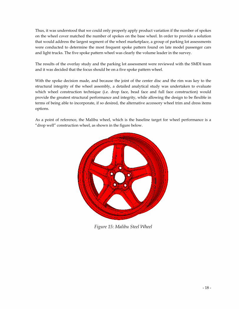
Thus, it was understood that we could only properly apply product variation if the number of spokes on the wheel cover matched the number of spokes on the base wheel. In order to provide a solution that would address the largest segment of the wheel marketplace, a group of parking lot assessments were conducted to determine the most frequent spoke pattern found on late model passenger cars and light trucks. The five spoke pattern wheel was clearly the volume leader in the survey. The results of the overlay study and the parking lot assessment were reviewed with the SMDI team and it was decided that the focus should be on a five spoke pattern wheel. With the spoke decision made, and because the joint of the center disc and the rim was key to the structural integrity of the wheel assembly, a detailed analytical study was undertaken to evaluate which wheel construction technique (i.e. drop face, bead face and full face construction) would provide the greatest structural performance and integrity, while allowing the design to be flexible in terms of being able to incorporate, if so desired, the alternative accessory wheel trim and dress items options. As a point of reference, the Malibu wheel, which is the baseline target for wheel performance is a “drop well” construction wheel, as shown in the figure below.
Figure 15: Malibu Steel Wheel
- 19 -
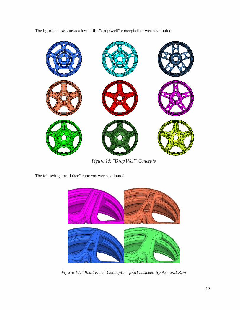
The figure below shows a few of the “drop well” concepts that were evaluated.
Figure 16: “Drop Well” Concepts
The following “bead face” concepts were evaluated.
Figure 17: “Bead Face” Concepts – Joint between Spokes and Rim

- 20 -
Finally, based on the preliminary structural studies of the various wheel construction techniques, one concept was retained due to its promising stiffness and mass savings opportunities.
Figure 18: Concept 1
In addition, another concept was obtained by morphing the above design into a “Full Face” concept.
Figure 19: Concept 2
Both concepts were further evaluated and studied in order to optimize their masses and performances. Gauge optimization combined with size and shape optimization was used to determine the lightweight steel designs which performance are described in paragraph 8.
- 21 -
8 Proposed Designs
8.1 Malibu Wheel
As mentioned earlier, the Malibu steel wheel was used for the project’s performance target. Since there was no steel wheel option for the Terrain vehicle, we had to establish a steel wheel baseline reference; the team chose the Malibu steel wheel because it was an optimized design and because it was of roughly the same GVW as the Terrain. Altair ProductDesign bought a Malibu steel wheel and wheel cover and created CAD models of each by reverse-engineering them. The CAD replication was deemed sufficiently accurate via a detailed visual comparison, numerous dimensional measurements, gauge checks and finally a mass comparison of the derived CAD model vs. the mass of the physical parts. As such, it was utilized in confidence for building our Finite Element model of the Malibu wheel and deriving our baseline performance targets for the lightweight wheel concept. Note: The Malibu steel wheel does not fit in the Terrain package space and is heavier (10.70 kg) than the 10-kg mass target.
8.2 Stiffness comparison
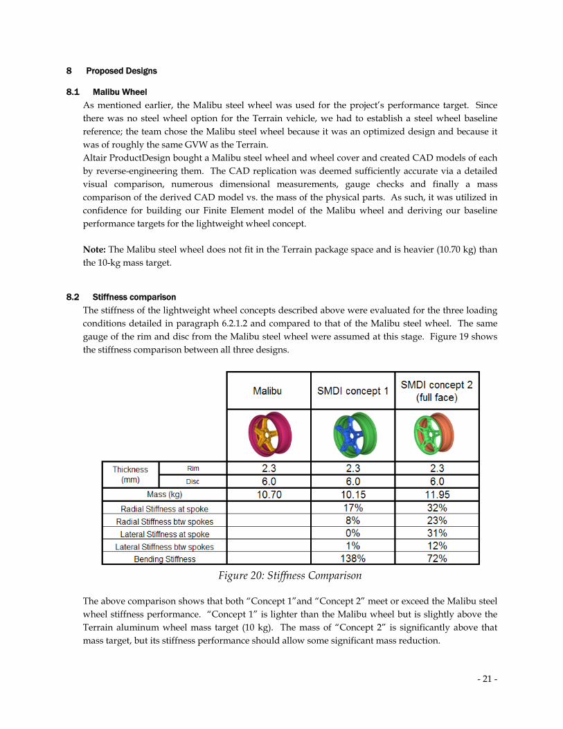
The stiffness of the lightweight wheel concepts described above were evaluated for the three loading conditions detailed in paragraph 6.2.1.2 and compared to that of the Malibu steel wheel. The same gauge of the rim and disc from the Malibu steel wheel were assumed at this stage. Figure 19 shows the stiffness comparison between all three designs.
Figure 20: Stiffness Comparison
The above comparison shows that both “Concept 1”and “Concept 2” meet or exceed the Malibu steel wheel stiffness performance. “Concept 1” is lighter than the Malibu wheel but is slightly above the Terrain aluminum wheel mass target (10 kg). The mass of “Concept 2” is significantly above that mass target, but its stiffness performance should allow some significant mass reduction.

- 22 -
8.3 Gauge Optimization
A gauge optimization was conducted on both concepts above in order to reduce their masses while maintaining comparable performance to the Malibu steel wheel. Manufacturing was also considered in the gauge reduction process by using Flow Forming, which allows using different thicknesses in different areas of a part (rim, disc or both). Note: When the disc was flow-formed, the cutouts shown in the disc were removed. The table below shows a comparison between different gauges configurations for Concept 1.
Figure 21: Concept 1 – Gauge optimization
All the configurations show similar comparable stiffness performance to the Malibu steel wheel design.
The table below shows a comparison between different gauges configurations for Concept 2. No flow-form parts were considered for this concept.
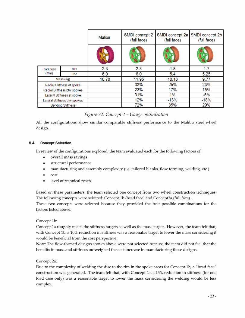
- 23 -
Figure 22: Concept 2 – Gauge optimization All the configurations show similar comparable stiffness performance to the Malibu steel wheel design.
8.4 Concept Selection
In review of the configurations explored, the team evaluated each for the following factors of: • overall mass savings • structural performance • manufacturing and assembly complexity (i.e. tailored blanks, flow forming, welding, etc.) • cost • level of technical reach
Based on these parameters, the team selected one concept from two wheel construction techniques. The following concepts were selected: Concept 1b (bead face) and Concept2a (full face). These two concepts were selected because they provided the best possible combinations for the factors listed above. Concept 1b: Concept 1a roughly meets the stiffness targets as well as the mass target. However, the team felt that, with Concept 1b, a 10% reduction in stiffness was a reasonable target to lower the mass considering it would be beneficial from the cost perspective. Note: The flow-formed designs shown above were not selected because the team did not feel that the benefits in mass and stiffness outweighed the cost increase in manufacturing these designs. Concept 2a: Due to the complexity of welding the disc to the rim in the spoke areas for Concept 1b, a “bead face” construction was generated. The team felt that, with Concept 2a, a 13% reduction in stiffness (for one load case only) was a reasonable target to lower the mass considering the welding would be less complex.
- 24 -
It should be noted that the Malibu steel wheel does not fit in the Terrain package space nor does it meet the 10-kg mass target that was set in this study, thus using the Malibu performance for this study represented a significant challenge for the objectives of this project.
8.5 Strength Study
The stress levels of the previously selected designs were monitored and a material selection was made for each component. Note: A large selection of High-Strength Steel materials were at the disposal of the team, however the analysis showed that using High-Strength Steel was not necessary for the structural integrity for the disc and rim. The Malibu steel wheel uses the following material:
- Disc: SAE J2340 380Y steel grade (yield strength of approximately 380 MPa) - Rim: SAE J2340 300Y steel grade (yield strength of approximately 300 MPa)
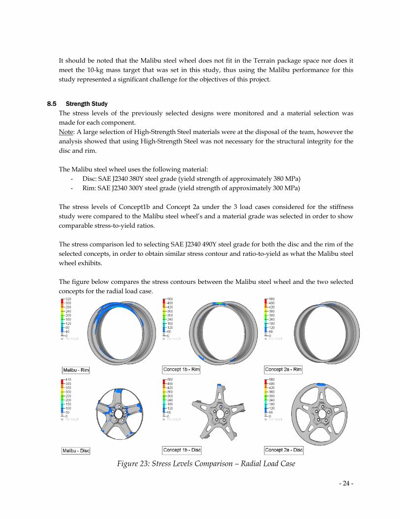
The stress levels of Concept1b and Concept 2a under the 3 load cases considered for the stiffness study were compared to the Malibu steel wheel’s and a material grade was selected in order to show comparable stress-to-yield ratios. The stress comparison led to selecting SAE J2340 490Y steel grade for both the disc and the rim of the selected concepts, in order to obtain similar stress contour and ratio-to-yield as what the Malibu steel wheel exhibits. The figure below compares the stress contours between the Malibu steel wheel and the two selected concepts for the radial load case.
Figure 23: Stress Levels Comparison – Radial Load Case

- 25 -
The figure below compares the stress contours between the Malibu steel wheel and the two selected concepts for the lateral load case.
Figure 24: Stress Levels Comparison – Lateral Load Case The figure below compares the stress contours between the Malibu steel wheel and the two selected concepts for the bending load case.
Figure 25: Stress Levels Comparison – Bending Load Case
- 26 -
8.6 Formability Study
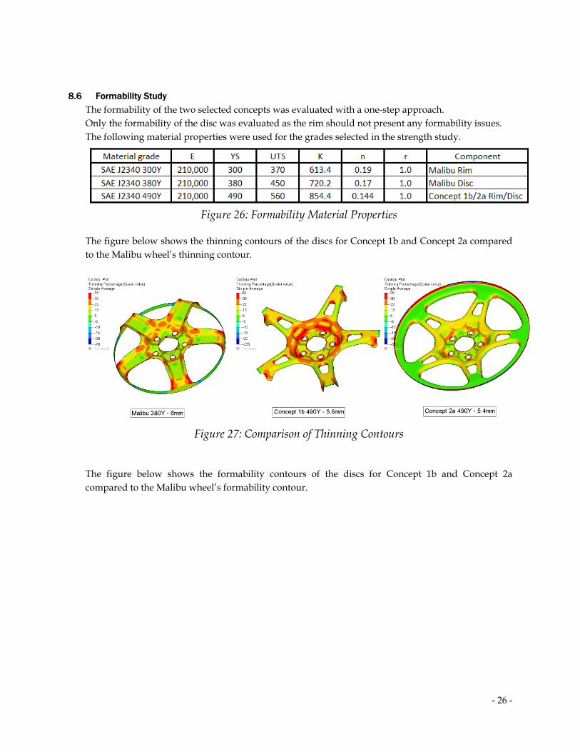
The formability of the two selected concepts was evaluated with a one-step approach. Only the formability of the disc was evaluated as the rim should not present any formability issues. The following material properties were used for the grades selected in the strength study.
Figure 26: Formability Material Properties
The figure below shows the thinning contours of the discs for Concept 1b and Concept 2a compared to the Malibu wheel’s thinning contour.
Figure 27: Comparison of Thinning Contours
The figure below shows the formability contours of the discs for Concept 1b and Concept 2a compared to the Malibu wheel’s formability contour.

- 27 -
Figure 28: Comparison of Formability Contours The one-step results above shows similar performance between the Malibu wheel and the Concept 1b and Concept 2a selected.
To get a complete assessment of the formability of this part, an incremental forming analysis could be performed as part of a second phase of this project.
9 Cost Study
With the input of the SMDI team, the cost of the Terrain aluminum wheel is estimated between $40 and $50. Therefore, the cost target for the lightweight steel wheel is $25-$35, representing a 30% cost reduction.
In consideration that the concept wheel designs represent some assembly methods that are not in regular use by steel wheel manufacturers today, it was necessary to decide on a means to quantify relative cost in comparison to wheels already in the marketplace, assuming that some process modifications would need to be implemented by the wheel manufacturers to build these concept wheels as designed. A comparative cost estimate was derived through a consensus of the wheel suppliers, the Steel Market and the Altair ProductDesign teams. The comparative method used to develop this estimate calculated the acquisition cost differences between the Terrain aluminum wheel and the Malibu steel wheel by securing market pricing from numerous sources for each of the wheels and averaging the cost numbers for each wheel. The team then factored in rough assessments (as a delta percentage increase over a typical steel wheel) to account for the differences in materials and manufacturing methods used in the lightweight concept design steel wheels compared to the Malibu steel wheel.

- 28 -
The team derived the following: • The Malibu steel wheel was estimated to be about 46% below the estimated cost of the
aluminum Terrain wheel • Concept 1b steel wheel was estimated to be about 43% below the estimated cost of the
aluminum Terrain wheel • Concept 2a (“full face” concept) steel wheel was estimated to be about 40% below the
estimated cost of the aluminum Terrain wheel
10 Final Concept Selection
The entire SMDI team reviewed the results of the Concept 1b and 2a comparison studies (i.e. stiffness, strength, formability and cost), as well as the potential challenges in implementing a new design (Concept 1b requires an assembly welding operation not in regular use in the steel wheel industry today), against the overall program objectives. The team decided that Concept 1b offered the best match for the program objectives.
Figure 29: Lightweight Wheel Concept
11 Aesthetic Design Flexibility
With a highly styled base wheel realized, additional concept ideation was undertaken to depict the optional means to provide for year to year, model to model aesthetic design flexibility. The following image identifies different wheel dress components that could be applied individually or in combination, to provide unique wheel aesthetics over a base wheel.

- 29 -
Figure 30: Wheel Dress Ideas
12 Conclusions
Through a process that consisted of the following activities: • Topology/topography optimization that provided:
o Design inspiration for aesthetic shapes and spoke patterns o Definition of the optimal wheel construction from a choice of full face, bead seat and
drop well wheel o Definition of the optimal load path shape for the chosen number of spokes
• Gauge and shape optimization to refine the wheel geometry to maximize performance while minimizing mass
• Consideration of a wide range of materials including advanced high strength steels while finally selecting SAE J2340 490Y grade steel for both rim and disc
• Ideation and depiction of alternative accessory wheel trim and dress items options Concept 1a and Concept 2b show promising results for mass, performance and cost. Phase I of this study was an excellent foundation for a Phase II design investigation with physical testing validation.
The wheel concepts meet the goals and objectives set forth: • An optimized steel wheel alternative that met the assembly and package space of the GMC
Terrain aluminum cast wheel. • The optimized steel wheel met the mass and performance requirement of the aluminum
baseline wheel while offering at least 40% cost savings. • The optimized steel wheel provided a high style concept with an upgrade path to additional
aesthetic differentiation through application of alternate trim options. • The optimized steel wheel project provides OEMs and supply industry engineers with the
tools to develop lightweight wheel structures