Embed Size (px)
Citation preview

USE OF NANO MATERIAL IN SURFACE ENGINEERING
PRESENTED BY- VIPIN GAUTAM
ROLL NO- 3143519
MECHANICAL DEPTT.( I & P)
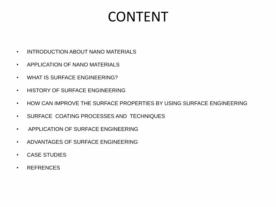
CONTENT
• INTRODUCTION ABOUT NANO MATERIALS
• APPLICATION OF NANO MATERIALS
• WHAT IS SURFACE ENGINEERING?
• HISTORY OF SURFACE ENGINEERING
• HOW CAN IMPROVE THE SURFACE PROPERTIES BY USING SURFACE ENGINEERING
• SURFACE COATING PROCESSES AND TECHNIQUES
• APPLICATION OF SURFACE ENGINEERING
• ADVANTAGES OF SURFACE ENGINEERING
• CASE STUDIES
• REFRENCES
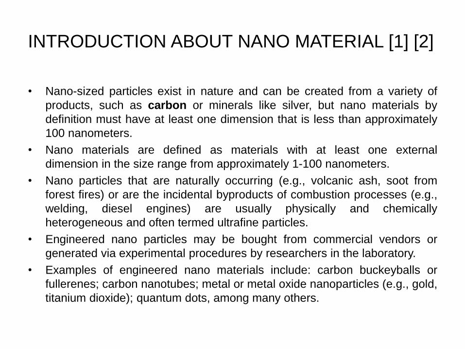
INTRODUCTION ABOUT NANO MATERIAL [1] [2]
• Nano-sized particles exist in nature and can be created from a variety of
products, such as carbon or minerals like silver, but nano materials by
definition must have at least one dimension that is less than approximately
100 nanometers.
• Nano materials are defined as materials with at least one external
dimension in the size range from approximately 1-100 nanometers.
• Nano particles that are naturally occurring (e.g., volcanic ash, soot from
forest fires) or are the incidental byproducts of combustion processes (e.g.,
welding, diesel engines) are usually physically and chemically
heterogeneous and often termed ultrafine particles.
• Engineered nano particles may be bought from commercial vendors or
generated via experimental procedures by researchers in the laboratory.
• Examples of engineered nano materials include: carbon buckeyballs or
fullerenes; carbon nanotubes; metal or metal oxide nanoparticles (e.g., gold,
titanium dioxide); quantum dots, among many others.

APPLICATION OF NANOMATERIALS [6]
• Nanocomposite materials: nanoparticle silicate nanolayer (claynanocomposites) and nanotubes can be used as reinforzed filler not only toincrease mechanical properties of nanocomposites but also to impart newproperties (optical, electronic etc.).
• Nanocoatings: surface coating with nanometre thickness of nanomaterialcan be used to improve properties like wear and scratch-resistant,optoelectronics, hydrophobic properties.
• Hard cutting tools: current cutting tools (e.g. mill machine tools) are madeusing a sort of metal nanocomposites such as tungsten carbide, tantalumcarbide and titanium carbide that have more wear and erosion-resistant,and last longer than their conventional (large-grained) materials.
• Using nanotechnology based knowledge may be produce more efficient,lightweight, high-energy density batteries.
WHAT IS SURFACE ENGINEERING [3]
• Surface engineering is the sub-discipline of materials science which
deals with the surface of solid matter.
• Solids are composed of a bulk material covered by a surface. The
surface which bounds the bulk material is called the Surface phase.
• The surface phase of a solid interacts with the surrounding
environment. This interaction can degrade the surface phase over time.
• Surface engineering involves altering the properties of the Surface Phase in
order to reduce the degradation over time.
• This is accomplished by making the surface robust to the environment in
which it will be used.
HISTORY OF SURFACE ENGINEERING [4]
• Surface engineering can be traced as far back as Thomos Edison in 1900
with the planting of gold films.
• In 1938, Berghaus was among the first to devlop plasma and ion
modification of surface to improve surface properties and surface of vaccum
deposited coatings.
• The ion plating process devloped in the early 1960’s was a significant step
forwarding in plasma assisted coated deposition.
• Ion plating was the first true industrial surface engineering process.
• After the early 1970’s the history of surface engineering intemately
connected to the development of thin film deposition and plasma processes.
HOW CAN IMPROVE THE SURFACE PROPERTIES BY
USING SURFACE ENGINEERING [4]
• An engineering component usually fails when its surface cannot adequately
withstand the external forces or environment to which it is subjected. The
choice of a surface material with the appropriate thermal, optical, magnetic
and electrical properties and sufficient resistance to wear, corrosion and
degradation, is crucial to its functionality.
• Improving the functionality of an existing product is only one aim of surface
engineering.
• Surface engineering provides additional functionality to solid surfaces,
involves structures and compositions not found naturally in solids,is used to
modify the surface properties of solids, and involves application of thin film
coatings, surface functionalization and activation,and plasma treatment.
SURFACE COATING PROCESSES AND TECHNIQUES
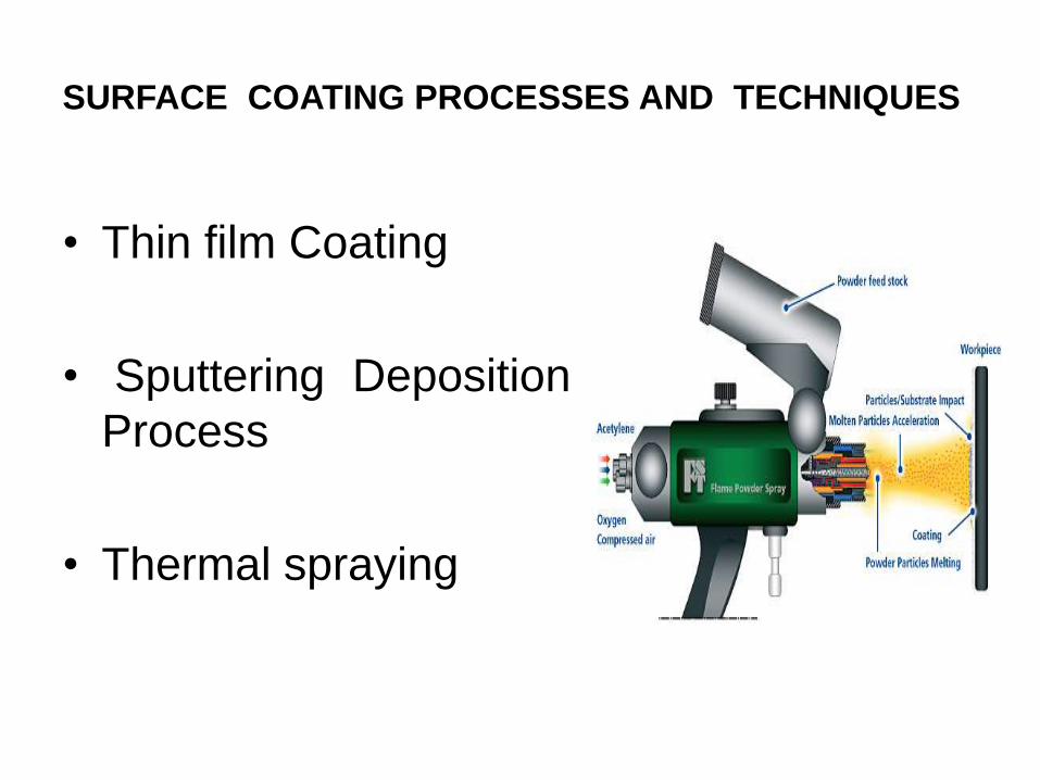
• Thin film Coating
• Sputtering Deposition
Process
• Thermal spraying
THIN FILM COATING [5]
• There are a number of deposition methods available. Among them, PVD and
CVD are commonly used.
• In the process of PVD, coating vapours are generated either by evaporation
from a molten source, or by ejection of atoms from a solid source that is
subject to bombardment by an ionised gas.
• The vapour may then be left as a stream of neutral atoms in a vacuum or it
may be ionised.
• A partially ionised stream is usually mixed with an ionised gas and then
deposited on an earthed or biased substrate, though a highly ionised stream
that forms plasma is attracted to a biased substrate
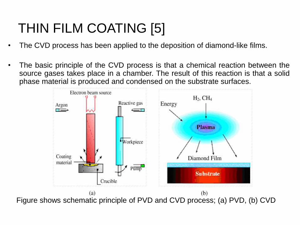
THIN FILM COATING [5]• The CVD process has been applied to the deposition of diamond-like films.
• The basic principle of the CVD process is that a chemical reaction between thesource gases takes place in a chamber. The result of this reaction is that a solidphase material is produced and condensed on the substrate surfaces.
Figure shows schematic principle of PVD and CVD process; (a) PVD, (b) CVD
SPUTTERING DEPOSITION PROCESS [5]
• Sputtering is a process whereby coating material is dislodged and ejected
form a solid surface caused by bombardment of high energy particles.
• The high energy particles are usually positive ions (and energetic neutrals)
of a heavy inert gas or species of coating material.
• The sputtered material is ejected primarily in atomic form from the source
of the coating material, called the target.
• The basic processes involving sputtering are: glow discharge and ion beam.
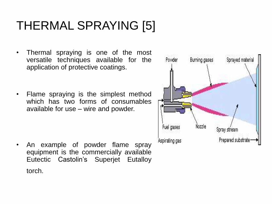
THERMAL SPRAYING [5]
• Thermal spraying is one of the mostversatile techniques available for theapplication of protective coatings.
• Flame spraying is the simplest methodwhich has two forms of consumablesavailable for use – wire and powder.
• An example of powder flame sprayequipment is the commercially availableEutectic Castolin’s Superjet Eutalloy
torch.
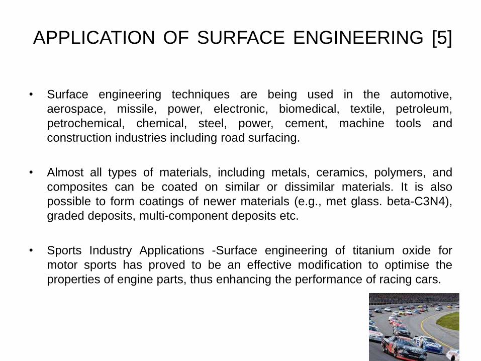
APPLICATION OF SURFACE ENGINEERING [5]
• Surface engineering techniques are being used in the automotive,
aerospace, missile, power, electronic, biomedical, textile, petroleum,
petrochemical, chemical, steel, power, cement, machine tools and
construction industries including road surfacing.
• Almost all types of materials, including metals, ceramics, polymers, and
composites can be coated on similar or dissimilar materials. It is also
possible to form coatings of newer materials (e.g., met glass. beta-C3N4),
graded deposits, multi-component deposits etc.
• Sports Industry Applications -Surface engineering of titanium oxide for
motor sports has proved to be an effective modification to optimise the
properties of engine parts, thus enhancing the performance of racing cars.

ADVANTAGES OF SURFACE ENGINEERING [4]
• Lower manufacturing cost
• Reduced life cycle cost
• Extended maintenance intervals
• Enhanced recyclability of materials
• Reduced environmental impact
CASE STUDY [7]
Temperature dependence of the residual
stresses and mechanical properties in TiN/CrN
nanolayered coatings processed by cathodic
arc deposition
ABSTRACT
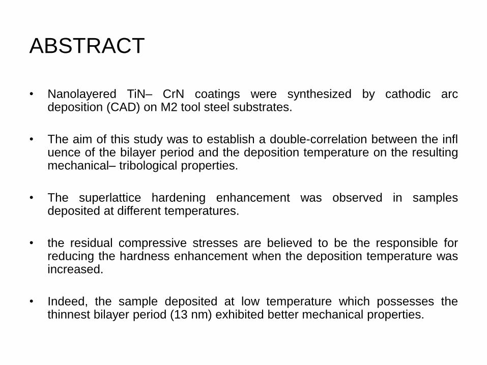
• Nanolayered TiN– CrN coatings were synthesized by cathodic arcdeposition (CAD) on M2 tool steel substrates.
• The aim of this study was to establish a double-correlation between the influence of the bilayer period and the deposition temperature on the resultingmechanical– tribological properties.
• The superlattice hardening enhancement was observed in samplesdeposited at different temperatures.
• the residual compressive stresses are believed to be the responsible forreducing the hardness enhancement when the deposition temperature wasincreased.
• Indeed, the sample deposited at low temperature which possesses thethinnest bilayer period (13 nm) exhibited better mechanical properties.

DEPOSITION PARAMETERS
• Target current ≈100 A
• Target voltage ≈−20 V
• Nitrogen pressure 2 Pa
• Substrates M2 HSS, 63 HRc
• Bias voltage range −150 V
• Turntable rotation speed 1 → 4 rpm
• Deposition time 90 min
• Deposition temperature ≈250 °C, 300° & 400 °C
EXPERIMENTAL PROCEDURE
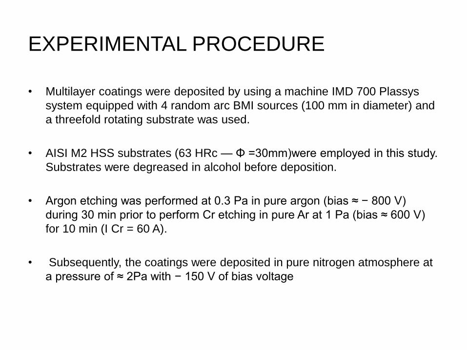
• Multilayer coatings were deposited by using a machine IMD 700 Plassys
system equipped with 4 random arc BMI sources (100 mm in diameter) and
a threefold rotating substrate was used.
• AISI M2 HSS substrates (63 HRc — Φ =30mm)were employed in this study.
Substrates were degreased in alcohol before deposition.
• Argon etching was performed at 0.3 Pa in pure argon (bias ≈ − 800 V)
during 30 min prior to perform Cr etching in pure Ar at 1 Pa (bias ≈ 600 V)
for 10 min (I Cr = 60 A).
• Subsequently, the coatings were deposited in pure nitrogen atmosphere at
a pressure of ≈ 2Pa with − 150 V of bias voltage
EXPERIMENTAL PROCEDURE
• In order to quantify the temperature effect on the mechanical– tribological
properties, samples were deposited at different temperatures in the
substrate holder without additional heating (labeled as RT)–final
temperature ≈ 250 °C– at 300 °C and at 400 °C.
• The fracture cross-section and polished surfaces were observed by means
of a thermal field emission scanning electron microscope.
• Profile composition was measured by glow discharge optical emission
spectroscopy (GD-OES).
• Depth profile analysis on substrates was conducted by means of Horiba RF
GD- Profiler 2 equipped with a 4 mm. diameter copper anode and operating
in Ar atmosphere.
EXPERIMENTAL PROCEDURE
• Hardness and the effective Young's modulus E *= E /(1 − ν 2 )where E andν are the Young's modulus and Poisson ratio respectively of coatings weremeasured by means of a nanohardness tester (NHT CSM Instruments)using a Berkovich diamond tip from loading/ unloading curves.
• Final values were calculated from an average of 40 indentations withimposed penetration depths shallower than 10% of the coating thickness,according to the Bückle's rule.
• Residual stress was determined using a bending method.
• Ball-on-disk tests were performed by using a CSM tribometer.
• A white-light profilometer (ALTISURF500) allowed to measure the 2-Dprofile les of the wear scars after ball-on-disk tests at four different areas.
RESULTS
Mechanical properties
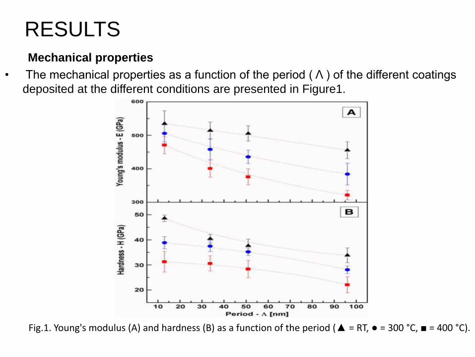
• The mechanical properties as a function of the period ( Λ ) of the different coatings
deposited at the different conditions are presented in Figure1.
Fig.1. Young's modulus (A) and hardness (B) as a function of the period (▲ = RT, ● = 300 °C, ■ = 400 °C).
Mechanical properties
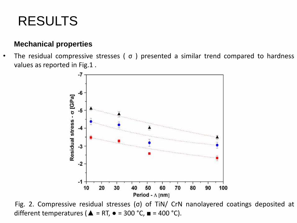
• The residual compressive stresses ( σ ) presented a similar trend compared to hardnessvalues as reported in Fig.1 .
Fig. 2. Compressive residual stresses (σ) of TiN/ CrN nanolayered coatings deposited atdifferent temperatures (▲ = RT, ● = 300 °C, ■ = 400 °C).
RESULTS
RESULTS
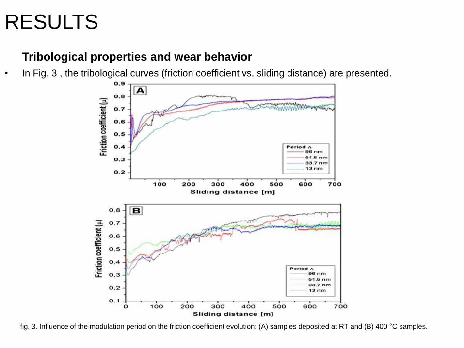
Tribological properties and wear behavior
• In Fig. 3 , the tribological curves (friction coefficient vs. sliding distance) are presented.
fig. 3. Influence of the modulation period on the friction coefficient evolution: (A) samples deposited at RT and (B) 400 °C samples.
RESULTS
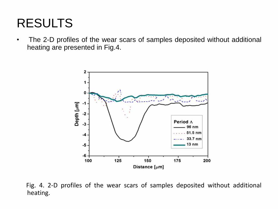
• The 2-D profiles of the wear scars of samples deposited without additionalheating are presented in Fig.4.
Fig. 4. 2-D profiles of the wear scars of samples deposited without additionalheating.
DISCUSSION
• Many efforts attempted to explain the strengthening of nanolayered coatings inthe 5– 20 nm bilayer period range. In fact, the superlattice effect is employed tojustify the enhancement of mechanical properties.
• It is well known that the superlattice effect essentially depends on the shearmoduli of the two materials.
• The maximum expected hardness enhancement may be explained by thefollowing formula-
Hmax= HA +3(GB − GA) sinθ / mπ^2
where H A is the hardness of the layer A with the lower shear modulus, G A andG B , the shear moduli of both materials (G B N G A ), m the Taylor factor and θ ,the smallest angle between the slip planes and the layer interfaces. If the TiN /CrN system is considered, CrN is A (G A =125GPa) and TiN is B(G B = 192GPa), respectively.
• In this study, the highest hardness enhancement is observed in the sampleprocessed without additional heating ascribed to the combination of the shortestperiod (13 nm) and the higher compressive stresses ( Fig.2 ).
DISCUSSION
• The influence of residual stresses on the hardness generates some
contradictions, since the mechanisms involved are not well identifi ed.
Nonetheless, it is believed that compressive residual stresses have an
important role in impeding the cracking during indentation, thus enhancing
the hardness.
• In single- phase coatings the cracks propagate perpendicularly to the
substrate/ coating interface until reaching the depth at the maximum stress
zone, thus generating high amount of debris. On the contrary, in
nanolayered coatings the interfaces play an important role as obstacles,
since the mobility of the cohesive cracks between the layers leading the
production of small amount of debris. This phenomenon permits to ex- plain
the enhancement in wear rate observed in the smaller bilayer periods, due
to the higher number of interfaces.
CONCLUSION
• The nanolayered TiN/CrN coatings were deposited on M2 tool steels by
cathodic arc deposition at different temperatures. These coatings exhibited
enhanced hardness compared with the single nitrides.
• No significant differences were measured in terms of tribological behavior
related to the mechanical properties. It seems that the role of number of
interfaces determined the final wear resistance, being higher when the
bilayer period thickness is decreased.
REFRENCES
1. https://web.stanford.edu/dept/EHS/.../nano/what_are_nanomaterials.html/23/10/2014
2. www.niehs.nih.gov/health/topics/agents/sya-nano/23/10/2014
3. http://en.wikipedia.org/wiki/Surface_engineering/24/10/2014
4. www.shef.ac.uk What is Surface Engineering? - University of Sheffield/26/10/2014
5. http://arrow.dit.ie/cgi/viewcontent.cgi?article=1027&context=engschmecart/26/10/2014
6. www.nanocompositech.com/nanotechnology/nanotechnology-applications.htm/5/11/2014
7. A Journal of Surface & Coatings Technology 238 (2014) 216– 222 by F. Lomello et al.