Embed Size (px)
Citation preview
! 11111""111111"1111111'"11"111111"11111111111""11111111113 117600166 1926-- --- - - -- -- -
NASA CR 165312 NI\SI\NASA-CR-165312
ICf g I 00 ( 3 ~'5 L( 'is
The Electric Rail Gunfor Space Propulsion
DAVID P, BAUERJOHN P, BARBER
INTERNATIONAL ApPLIED PHYSICSJ INC,
C. JULIAN VAHLBERG
BUSINESS AND TECHNOLOGICAL SYSTEMSJ INC,
FEBRUARY 1981
FINAL TECHNICAL REPORT:
CONTRACT No, NAS3-22475NASA-LEWIS RESEARCH CENTER
CLEVELAND J OHIO
https://ntrs.nasa.gov/search.jsp?R=19810013548 2019-05-24T00:02:15+00:00Z

,..---"./. INTERNATIONAL APPLIED PHYSICS INC.7546 MC EWEN RD. DAYTON, OHIO 450459
TELEPHONE: (513) 435-8752 • TELEX: 288278 • CABLE: INTALAP
28 April 1981
Dear Sir:
By request of Mr. William Kers1ake, NASA-Lewis Research
Center, Cleveland, please find enclosed one copy of NASA CR
165312, "The Electric Rail Gun for Space Propulsion." It is
the final technical report on contract number NAS3-22475.
David P. BauerResearch Engineer
DPB:nl

NASA CR 165312 NI\SI\
The Electric Rail Gunfor Space Propulsion
DAVID P, BAUERJOHN P, BARBER
INTERNATIONAL ApPLIED PHYSICS J INC.
C, JULIAN VAHLBERG
BUSINESS AND TECHNOLOGICAL SYSTEMSJ INC.
FEBRUARY 1981
FINAL TECHNICAL REPORT:
CONTRACT No, NAS3-22475NASA-LEWIS RESEARCH CENTER
CLEVELAND J OHIO

1. Report No.
NASA CR 1653122. Government Accession No. 3. Recipient's c.talog No.
4. Title and Subtitle
The Electric Rail Gun for Space Propulsion
7. Author(s)David P. Bauer, John P. Barber, C. Julian Vahlberg
9. Performing Organization Name and Address
International Applied Physics, Inc.7546 McEwen RoadDayton, Ohio 45459
5. Report Date
February 19816. Performing Organization Code
8. Performing Organization Report No.
10. Work Unit No. YOS 0939
RTOP 506-55-32
11. Contract or Grant No.
NAS3-22475
12. Sponsoring Agency Name and Address
National Aeronautical and Space AdministrationLewis Research Center21000 Brookparkr'1ouo1",,,,r'l nn;r. LlLI1.<=;
t- --l13. Type of Report and Period Covered
Final Report24 .Tllnp 1 qRO - ":\0 ,T"n 1 qR
14. Sponsoring Agency Code
15. Supplementary Notes
NASA Project Manager: W. R. Kerslake, NASA LeRC, Cleveland, Ohio
16. Abstract
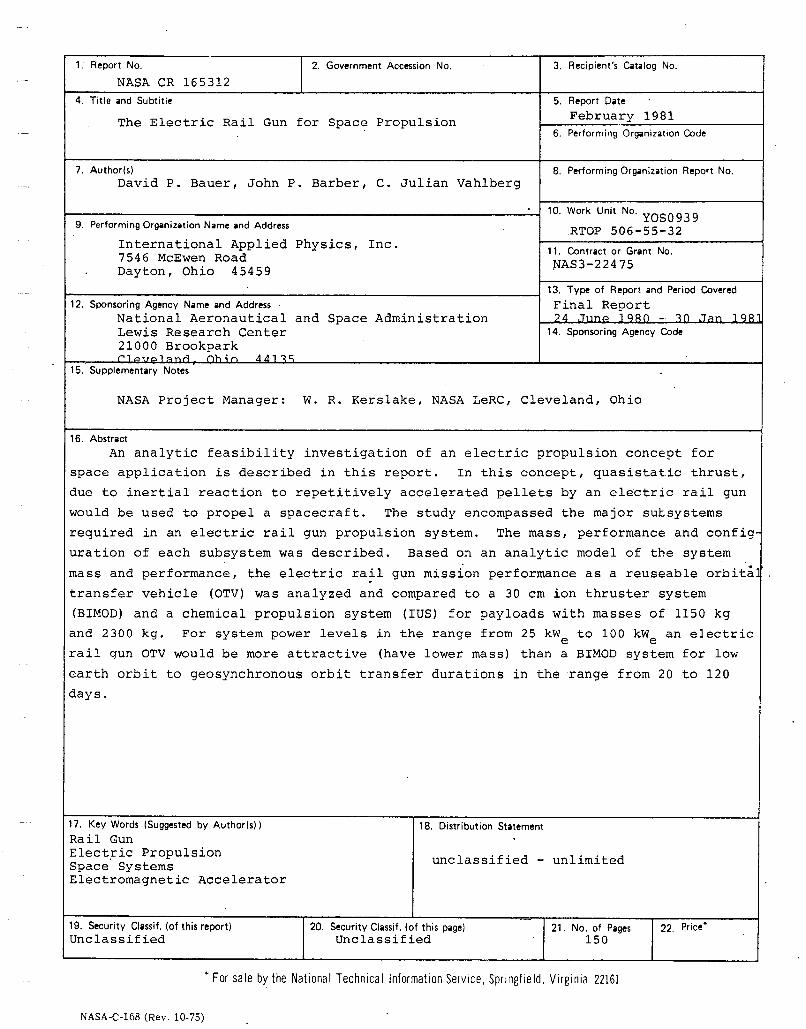
An analytic feasibility investigation of an electric propulsion concept for
space application is described in this report. In this concept, quasistatic thrust,
due to inertial reaction to repetitively accelerated pellets by an electric rail gun
would be used to propel a spacecraft. The study encompassed the major sULsystems
required in an electric rail gun propulsion system. The mass, performance and config
uration of each subsystem was described. Based on an analytic model of the system
mass and performance, the electric ra~l gun mission performance as a reuseable orbita
transfer vehicle (OTV) was analyzed and compared to a 30 cm ion thruster system
(BIMOD) and a chemical propulsion system (IUS) for payloads with masses of 1150 kg
and 2300 kg. For system power levels in the range from 25 kW to 100 kW an electrice erail gun OTV would be more attractive (have lower mass) than a BIMOD system for low
earth orbit to geosynchronous orbit transfer durations in the range from 20 to 120
days.
17. Key Words (Suggested by Author(s))
Rail GunElectric PropulsionSpace SystemsElectromagnetic Accelerator
18. Distribution Statement
unclassified - unlimited
19. Security Classif. (of this report)Unclassified
20. Security Classif. (of this pagelUnclassified
21. No. of Pages150
22. Price·
• For sale by the National Technical Information Service, Springfield. Virginia 22161
NASA-C-168 (Rev. 10-75)

SECTION
1
2
3
4
A
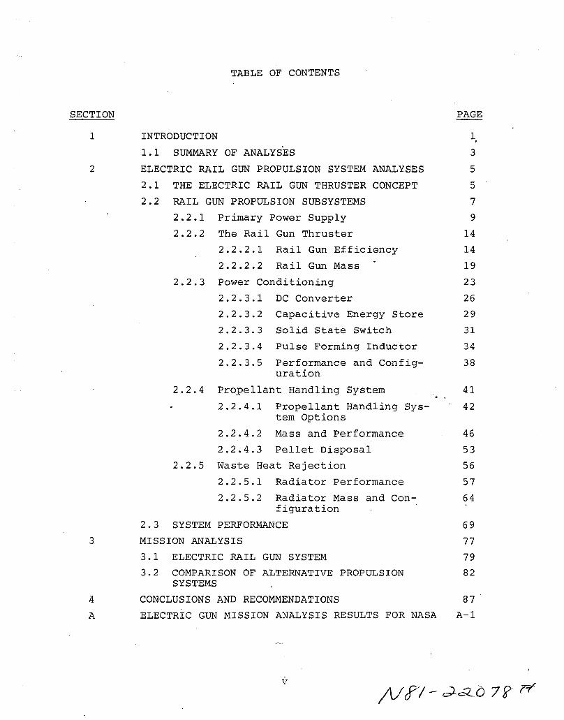
TABLE OF CONTENTS
INTRODUCTION
1.1 SUMMARY OF ANALYSES
ELECTRIC RAIL GUN PROPULSION SYSTEM ANALYSES
2.1 THE ELECTRIC RAIL GUN THRUSTER CONCEPT
2.2 RAIL GUN PROPULSION SUBSYSTEMS
2.2.1 Primary Power Supply
2.2.2 The Rail Gun Thruster
2.2.2.1 Rail Gun Efficiency
2.2.2.2 Rail Gun Mass
2.2.3 Power Conditioning
2.2.3.1 DC Converter
2.2.3.2 Capacitive Energy Store
2.2.3.3 Solid State Switch
2.2.3.4 Pulse Forming Inductor
2.2.3.5 Performance and Config-uration
2.2.4 Pr~pellant Handling System
2.2.4.1 Propellant Handling System Options
2.2.4.2 Mass and Performance
2.2.4.3 Pellet Disposal
2.2.5 Waste Heat Rejection
2.2.5.1 Radiator Performance
2.2.5.2 Radiator Mass and Con-figuration
2.3 SYSTEM PERFORMANCE
MISSION ANALYSIS
3.1 ELECTRIC RAIL GUN SYSTEM
3.2 COMPARISON OF ALTERNATIVE PROPULSIONSYSTEMS
CONCLUSIONS AND RECOMMENDATIONS
ELECTRIC GUN MISSION ANALYSIS RESULTS FOR NASA
PAGE
1,
3
5
5
7
9
14
14
19
23
26
29
31
34
38
41
42
46
53
56
57
64
69
77
79
82
87 .
A-I
v
LIST OF ILLUSTRATIONS
PAGE
1. A simple parallel rail electric gun. 6
2. The major electric rail gun propulsion subsystem. . 8
3. Solar cell electrical characteristics. 11
4. SEPS solar cell array wing. 13
5. Inductively driven rail gun simulation circuit. 16
.6. Electric rail gun cycle efficiency. 20
7. Rail gun cross section. 20
8. Major components of power conditioning system. 24
9. Circuit components of power conditioning system. 25
10. Block diagram of DC-DC series resonant converter. 27
11. Series resonant converter specific mass and effici- 29ency (from Reference 13).
12. Conceptual configuration of 25 kWe power condition- 40ing system.
13. Solid propellant pellet former. 51
14. Exhaust velocities which result in pellet stable 56orbits.
15. Meteoroid bumper protected radiator. 62
16. Bumper shielded and unshielded radiator performance 63comparison.
17. Radiator specific mass. 66
18. Rail gun radiator concept. 68
19. Coolant channels in rail gun. 69
20. Electric rail gun propulsion system mass compared 72to BIMOD.
21. Electric rail gun propulsion system efficiency com- 73pared to BIMOD.
vi
List of Illustrations (cont.)
PAGE
22. Conceptual configuration of electric rail gun pro- 74pulsion system.
23. Mass requirements to transfer a 2300 kg payload from 80LEO to GEO with a rail gun OTV.
24. Pellet exhaust velocity requirements to transfer a 802300 kg payload from LEO to GEO with a rail gun OTV.
25. Effect of reuseable verses one-way missions on rail 82gun propulsion system mass requirements.
26. Effect of payload mass on rail gun propulsion system 83mass requirements.
27. Comparison of alternative propulsion systems for one- 84way OTV missions.
vii
LIST OF TABLES
PAGE
1. Effect of SEPS Solar Cell Array Characteristics on 10Propulsion System
2. Parameters Effecting Rail Gun Efficiency 18
3. Summary of Capacitive Based Power Conditioning Mass 39and Performance
4. Propellant Handling System Options 43
viii

NOMENCLATURE
Df outside diameter of solid bar propellant coil
D ~ mandrel diameterm
Eke ::;;;
E ::;;;
s
I ::;;;
0
Lo::;;;
L' ~
M =c
Md =
MDC =
Mf =
Mff =
Mft =
ML =
MLR =
M =m
Mps =
M =r
M =s
Msf =
M =st
Msw
Mt .-
P =
P =pc
pellet kinetic energy
energy required to launch a pellet
maximum allowable rail gun current
inductance of rail gun drive inductor
inductance of rail gun per unit length
capacitive energy store mass
total clamp diode mass
DC converter mass
propellant mass
fluid pellet forming system effective mass
fluid propellant transport mass
mass of propellant handling/loading system
mass of pulse forming coil which satisfies efficiencyconstraint
preformed bar storage mandrel mass
solar cell array mass
radiator mass
total switch/clamp system ~ass
mass of solid pellet shear system
solid bar propellant transport mass
total thyristor switch mass
propellant tank mass
output power of solar cell array
power input to the power conditioner
Nomenclature (cont.)
Pr = thermal power to be rejected
P = average power required to shear solid propellant bars
Pt = propellant storage tank pressure
Q = heat of fusion
Ro = resistance of rail gun drive inductor
Rr = resistance of rail gun per unit length
T = average radiator temperature
TO = effective sink temperature
Vs = capacitor energy storage voltage
a = mean radius of Brook's coil
d = pellet length
d r = rail thickness
d s = rail gun confining structure thickness
d = average coil mass density
h
m
r e
r o
v
v.~
= rail gun bore size
BIMOD propellant system spacific mass
= specific mass
= pellet mass
= earth radius
= orbital radius, from center of earth
= pellet exhaust velocity
= pellet exhaust velocity which causes pellet capture byearth during LEO to GEO transfer
= pellet exhaust velocity which causes earth escape duringLEO to GEO transfer
= pellet exhaust velocity which causes pellet escape duringGEO to LEO transfer
x

Nomenclature (cont.)
w =
x =
(Xhr =
8 =
E: =
E: e =
na =
nc =
nr =
p =
° =
radiator specific radiated power (thermal power per unitsurface area)
rail gun length
specific mass of radiator
electrical skin depth
fraction of coil cross-section occupied by conductor (coilpacking factor)
emissivity
rail gun efficiency
capacitive energy store efficiency
refrigeration system efficiency
mass density
stress
= maximum allowable stress°00sb = Stefan-Boltzmann constant
L = solid propellant shear strength
La pellet launch time
xi

SECTION 1
INTRODUCTION
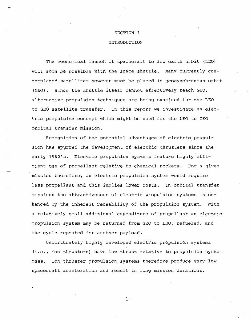
The economical launch of spacecraft to low earth orbit (LEO)
will soon be possible with the space shuttle. Many currently con
templated satellites however must be placed in geosynchronous orbit
(GEO). Since the shuttle itself cannot effectively reach GEO,
alternative propulsion techniques are being examined for the LEO
to GEO satellite transfer. In this report we investigate an elec
tric propulsion concept which might be used for the LEO to GEO
orbital transfer mission.
Recognition of the potential advantages of electric propul
sion has spurred the development of electric thrusters since the
early 1960's. Electric propulsion systems feature highly effi
cient use of propellant relative to chemical rockets. For a given
mission therefore, an electric propulsion system would require
less propellant and this implies lower costs. In orbital transfer
missions the attractiveness of electric propulsion systems is en
hanced by the inherent reusability of the propulsion system. With
a relatively small additional expenditure of propellant an electric
propulsion system may be returned from GEO to LEO, refueled, and
the cycle repeated for another payloaq.
Unfortunately highly developed electric propulsion systems
(i.e., ion thrusters) have low thrust relative to propulsion system
mass. Ion thruster propulsion systems therefore produce very low
spacecraft acceleration and result in long mission durations.
-1-
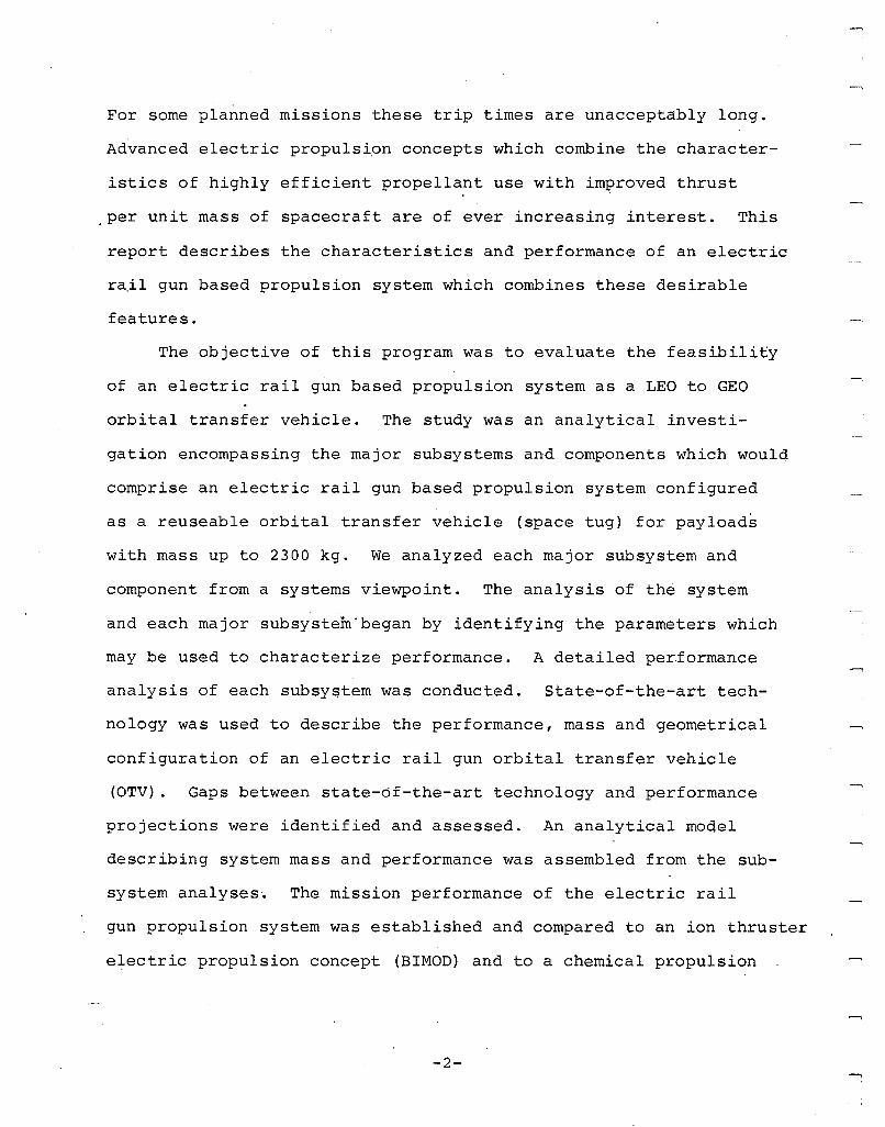
For some planned missions these trip times are unacceptably long.
Advanced electric propulsion concepts which combine the character
istics of highly efficient propellant use with improved thrust
.per unit mass of spacecraft are of ever increasing interest. This
report describes the characteristics and performance of an electric
ra.il gun based propulsion system which combines these desirable
features.
The objective of this program was to evaluate the feasibility
of an electric rail gun based propulsion system as a LEO to GEO
orbital transfer vehicle. The study was an analytical investi
gation encompassing the major subsystems and components which would
comprise an electric rail gun based propulsion system configured
as a reuseable orbital transfer vehicle (space tug) for payloads
with mass up to 2300 kg. We analyzed each major subsystem and
component from a systems viewpoint. The analysis of the system
and each major sUbsystem'began by identifying the parameters which
may be used to characterize performance. A detailed performance
analysis of each subsyqtem was conducted. state-of-the-art tech
nology was used to describe the performance, mass and geometrical
configuration of an electric rail gun orbital transfer vehicle
(OTV). Gaps between state-of-the-art technology and performance
projections were identified and assessed. An analytical model
describing system mass and performance was assembled from the sub
system analyses~ The mission performance of the electric rail
gun propulsion system was established and compared to an ion thruster
electric propulsion concept (BIMOD) and to a chemical propulsion
-2-
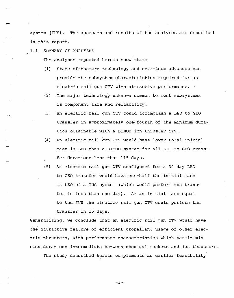
system (IUS). The approach and results of the analyses are described
in this report.
1.1 SUMMARY OF ANALYSES
The analyses reported herein show that:
(1) State-of-the-art technology and near-term advances can
provide the sUbsystem characteristics required for an
electric rail gun OTV with attractive performance.
(2) The major technology unknown common to most subsystems
is component life and reliability.
(3) An electric rail gun OTV could accomplish a LEO to GEO
transfer in approximately one-fourth of the minimum dura
tion obtainable with a BIMOD ion thruster OTV.
(4) An electric rail gun OTV would have lower total initial
mass in LEO than a BIMOD system for all LEO to GEO trans
fer durations less than 115 days.
(5) An electric rail gun OTV configured for a 30 day LEO
to GEO transfer would have one-half the initial mass
in LEO of a IUS system (which would perform the trans
fer in less than one day). At an initial mass equal
to the IUS the electric rail gun OTV could perform the
transfer in 15 days.
Generalizing, we conclude that an electric rail gun OTV would h~ve
the attractive feature of efficient propellant usage of other elec
tric thrusters, with performance characteristics which permit mis-
sion durations intermediate between. chemical rockets and ion thrusters.
The study described herein complements an earlier feasibility
-3-
study of the electric rail gun propulsion concept as a reuseable
OTV for much larger payloads (i.e., payload mass up to 22,700 kg).l
Much of the analysis developed in Reference 1 was used, with the
primary emphasis on evaluating scaled-down characteristics for
the various subsystems.
The analysis and results of this electric rail gun propul-
sion system study are described in the remaining three sections
of this report. Section 2 begins with a brief review of the elec-
tric rail gun concept and its application to a propulsion system.
The major components and subsystems comprising an electric rail
gun propulsion system are identified. The performance of each
subsystem is described and conceptual sketches showing the essential
features of the subsystem are provided. Section 2 concludes with
a system mass and performance description assembled from the sub-
system analyses. Section 3 describes the mission analyses and
performance of the rail gun propulsion system as an orbital trans-
fer vehicle. The mission performance of the electric rail gun
propulsion system is compared to that of a BIMOD system and an
IUS system. The relative advantages and disadvantages of each
system are described. In Section 4 we discuss electric rail gun
propulsion system feasibility and outline our conclusions. We
also describe the technological developmental requirements and
suggest approaches to satisfy these requirements.
1Bauer, D., Barber, J., Swif~ H., and Vahlberg, C., "Electric RailGun Propulsion Study (Advanced Electric Propulsion Technology HighThrust)", Air Force Rocket Propulsion Laboratory, AFRPL-TR-8l-02,December 1980.
-4-
....,
SECTION 2
ELECTRIC RAIL GUN PROPULSION SYSTEM ANALYSIS
This section begins with a description of the electric rail
gun concept and its application to space propulsion. The major
subsystems required in an electric rail gun propulsion system are
identified. The mass, performance and conceptual configuration
of each subsystem are described. A system mass and performance
description is assembled and compared to the BIMOD system.
2.1 THE ELECTRIC RAIL GUN THRUSTER CONCEPT
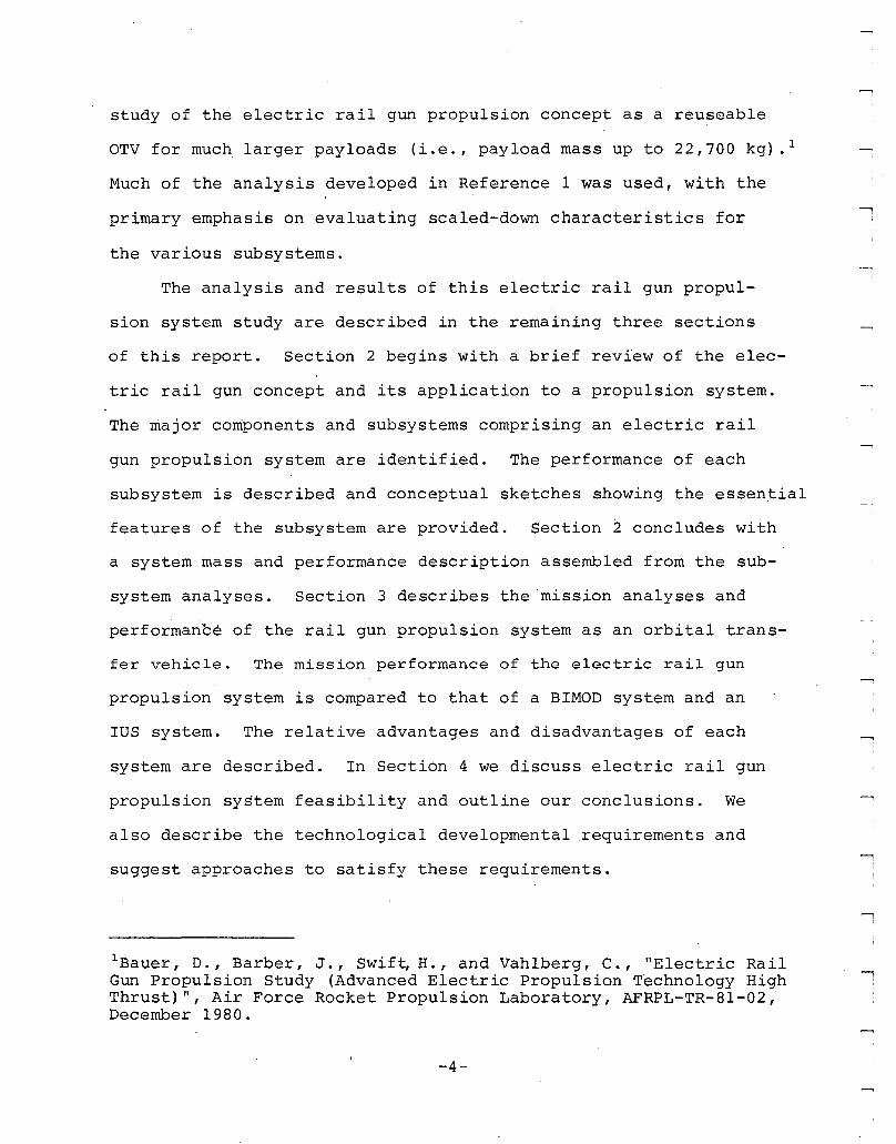
A simple parallel rail gun consists of a pair o£ electrodes
which form two opposite sides of a rectangular bore accelerator
channel. The other two sides which complete the bore are made
up of a dielectric material. A rectangular parallelepiped pro-
jectile (pellet) is placed in the gun bore as shown in Figure 1.
At the rear of the projectile an electrically conducting armature
contacts each of the rails. An electrical potential, applied across
'the rails at the breech, drives current down one rail through the
electrically conducting armature and back to the breech through
the other rail. Current in the rails produces a magnetic field
between the rails. The current flowing in the armature interacts
with the magnetic field to produce a force which accelerates the
armature and projectile. Projectile velocities of 6 km/s have
been demonstrated with electric rail guns and recent experiments
may have reached as h~gh as 10 km/s. 2'3 A complete description
2 Rashleigh, S., and Marshall, R., "Electromagnetic Acceleration ofMacroparticles to High Velocities," J. Appl. Phys., March 1978.
3 Hawke, R., et aI, "Results of Railgun Experiments Powered by Magnetic Flux Compression Generators," Lawrence Livermore NationalLaboratory, UCRL-84875, 1980.
-5-
PELLET
ARMATURE
RAIL
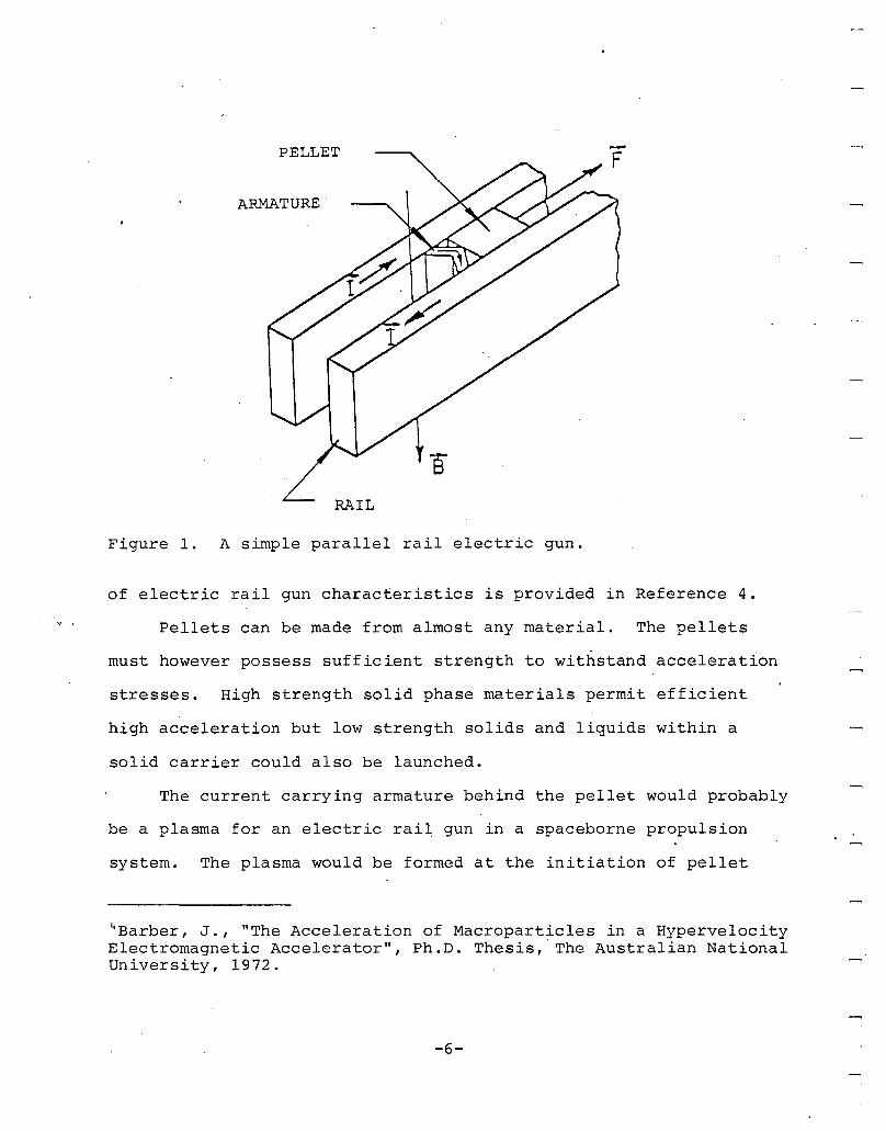
Figure 1. A simple parallel rail electric gun.
of electric rail gun characteristics is provided in Reference 4.
Pellets can be made from almost any material. The pellets
must however possess sufficient strength to withstand acceleration
stresses. High strength solid phase materials permit efficient
high acceleration but low strength solids and liquids within a
solid carrier could also be launched.
The current carrying armature behind the pellet would probably
be a plasma for an electric rail gun in a spaceborne propulsion
system. The plasma would be formed at the initiation of pellet
4 Barber, J., "The Acceleration of Macroparticles in a HypervelocityElectromagnetic Accelerator", Ph.D. Thesis,· The Australian NationalUniversity, 1972.
-6-
launch, by exploding a thin metallic foil. Plasma pressure on
the rear of the pellet would cause acceleration. Close pellet
conformity to the rail gun bore would be required for plasma ob
turation.
Inertial reaction to the accelerated pellet (gun recoii) pro
duces a force in the rail gun opposite in direction to the pellet
velocity vector. A spacecraft could be propelled with the quasi
static thrust generated by launching pellets repetitively.
2.2 RAIL GUN PROPULSION SUBSYSTEMS
In an electric propulsion system the rail gun is the device
which converts electrical energy to kinetic energy and propul
sive thrust. In addition to the rail gun thruster, several essen-
'tial subsystems comprise the complete space propulsion system.'
In the study reported herein our objective was to exam~ne all the
subsystems which could effect the feasibility of the electric rail
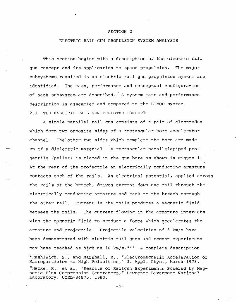
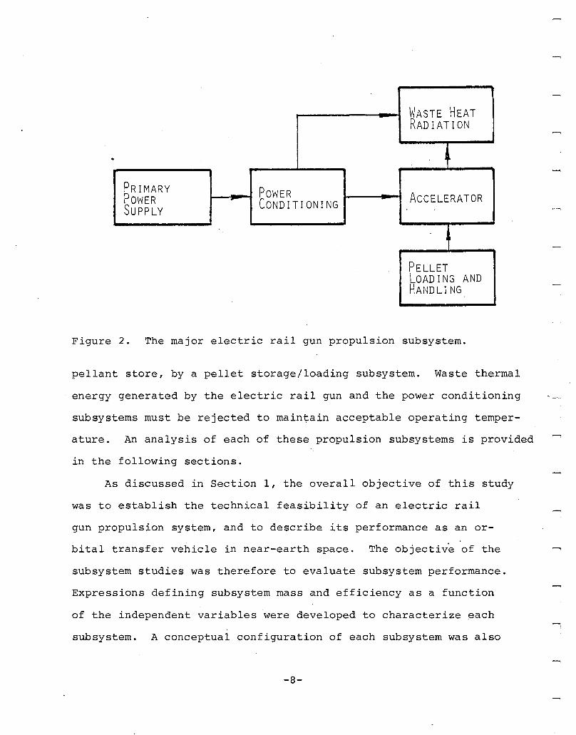
gun propulsion concept. Figure 2 shows the five major subsystems
on which the concept feasibility study was based. Each of the
five subsystems is associated with major power flow in the pro
pulsion system and/or represents one of the major components of
system mass. The primary power source supplies the average system
power required for propulsion. A power conditioning system is
required to convert the average pow~r.from the primary supply to
high power, high current pulses required to drive the rail gun.
The rail gun itself then converts these high current electrical
pulses to pellet kinetic energy. Pellets are loaded into the breech
of. the rail gun at the required pulse ~epetition rate from a pro-
-7-
WASTE HEATRADIATION
.
PRIMARY POWER ACCELERATORPOWER r
CONDITIONINGSUPPLY
PELLETLOADING ANDHANDLING
Figure 2. The major electric rail gun propulsion subsystem.
pellant store, by a pellet storage/loading subsystem. Waste thermal
energy generated by the electric rail gun and the power conditioning
subsystems must be rejected to maintain acceptable operating temper-
ature. An analysis of each of these propulsion subsystems is provided
in the following sections.
As discussed in Section 1, the overall objective of this study
was to establish the technical feasibility of an electric rail
gun propulsion system, and to describe its performance as an or
bital transfer vehicle in near-earth space. The objective of the
subsystem studies was therefore to evaluate subsystem performance.
Expressions defining subsystem mass and efficiency as a function
of the independent variables 'were developed to characterize ~ach
subsystem. A conceptual configuration of each subsystem was also
-8-

developed in the course of these analyses. The subsystem analyses
are described in the following paragraphs.
2.2.1 Primary Power Supply
In this study the propulsion system primary power source
was assumed to be a solar cell array with SEPS type solar cell
array characteristics. SEPS arrays have been designed for ion
thruster propulsion applications requiring power levels ranging
from 25 kWe to 100 kWe . s Propulsion power levels in this study
were limited to 25-100 kW. Most characteristics· designed intoe
the SEPS solar cell array for other electric propulsion applica-
tions make it attractive for application with the electric rail
gun propulsion concept. Details of the array are listed in Table
1. We discuss several of the SEPS array characteristics shown
in Table 1 and evaluate SEPS compatibil~ty to the electric rail
gun propulsion concept in the following paragraphs.
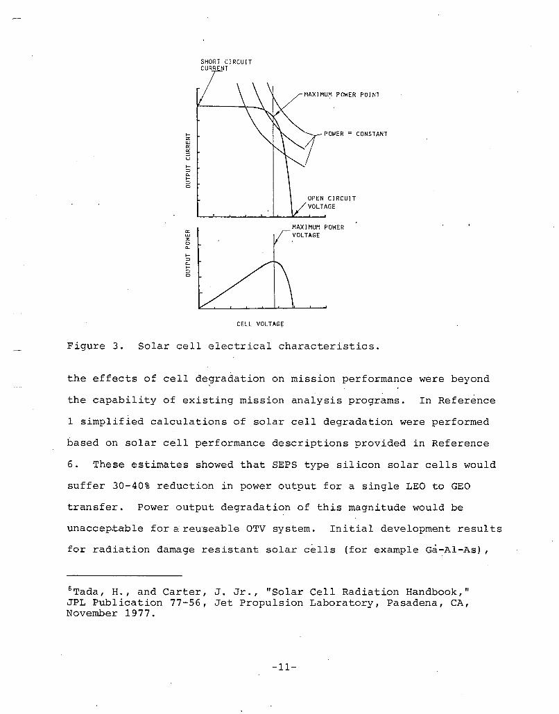
Solar cell electrical output characteristics influence
the power conditioning subsystem design requirements. A solar
cell behaves as a voltage limited current generator with internal
series resistance. Solar cell current voltage characteristics
are shown in Figure 3. These curves show that solar cells and
therefore solar cell arrays have a well defined peak output power
point. This implies t~at the array must be connected to a ~atched
SYoung, L., "Solar Array Technology for Solar Electric PropulsionMissions," AIAA Paper No. 79-3086, Presented at the 14th International Electric Propulsion Conference, Princeton, NJ, October 30 November 1, 1979.
-9-
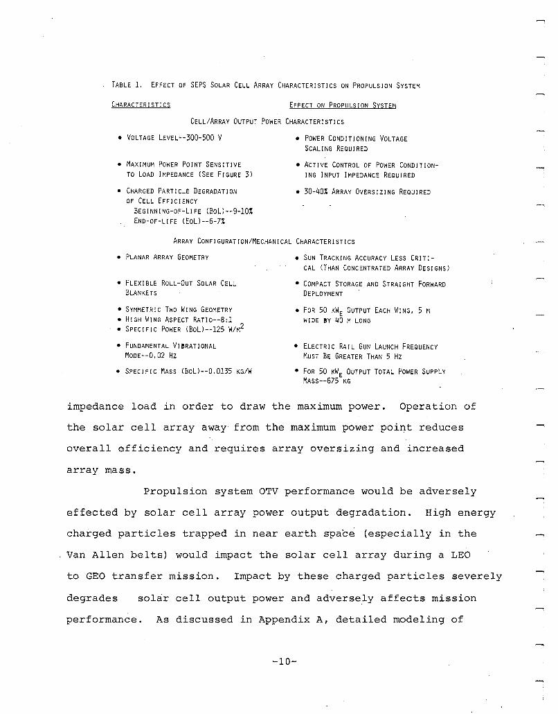
TABLE 1, EFFECT OF SEPS SOLAR CELL ARRAY CHARACTERISTICS ON PROPULSION SYSTEM
CHARACTER ISTI CS EFFECT ON PROPULSION SYSTEM
CELL/ARRAY OUTPUT POWER CHARACTERISTICS
• VOLTAGE LEVEL~-300-500 V
• MAXIMUM POWER POINT SENSITIVETO LOAD IMPEDANCE (SEE FIGURE 3l
• CHARGED PARTICLE DEGRADATIONOF CELL EFFICIENCY
BEGINNING-OF-LIFE (BoL)--9-10~
END-OF-LIFE (EoLl--6-7%
• POWER CONDITIONING VOLTAGESCALING REQUIRED
• ACTIVE CONTROL OF POWER CONDITIONING INPUT IMPEDANCE REQUIRED
• 30-40% ARRAY OVERSIZING REQUIRED
ARRAY CONFIGURATION/MECHANICAL CHARACTERISTICS
• PLANAR ARRAY GEOMETRY
• FLEXIBLE ROLL-OUT SOLAR CELLBLANKETS
• SYMMETRIC Two WING GEOMETRY• HIGH WING ASPECT RATlo--8:1• SPECIFIC POWER (BoLl--125 W/M2
• FUNDAMENTAL VI!RATIONALMODE--Q,02 Hz
• SPECIFIC MASS (BoLl--0,0135 KG/W
• SUN TRACKING ACCURACY LESS CRITI-CAL (THAN CONCENTRATED ARRAY DESIGNSl
• COMPACT STORAGE AND STRAIGHT FORWARDDEPLOYMENT
• FOR 50 KW E OUTPUT EACH WING, 5 MWIDE !Y 40 M LONG
• ELECTR IC RA I L GUN LAUNCH FREQUENCYMUST BE GREATER THAN 5 Hz
• FOR 50 KW E OUTPUT TOTAL POWER SUPPLYMASS--675 KG
impedance load in order to draw the maximum power. Operation of
the solar cell array away from the maximum power point reduces
overall efficiency and requires array oversizing and increased
array mass.
Propulsion system OTV performance would be adversely
effected by solar cell array power output degradation. High energy
charged particles trapped in near earth space (especially in the
Van Allen belts) would impact the solar cell array during a LEO
to GEO transfer mission. Impact by these charged particles severely
degrades sol~r cell output power and adversely affects mission
performance. As discussed in Appendix A, detailed modeling of
-10-
SHORT CIRCUITCURRENT
IZUJ
'"'":::>u
I:::>0I:::>o
'"UJ~o0-
I:::>0I:::>o
CELL VOLTAG~
MAXIMUM POWER POINT
OPEN CIRCUITVOLTAGE
MAXIMUM POWERVOLTAGE
Figure 3. Solar cell electrical characteristics.
the effects of cell degradation on mission performance were beyond
the capability of existing mission analysis programs. In Reference
1 simplified calculations of solar cell degradation were performed
based on solar cell performance descriptions provided in Reference
6. These estimates showed that SEPS type silicon solar cells would
suffer 30-40% reduction in power output for a single LEO to GEO
transfer. Power output degradation of this magnitude would be
unaccep.table for a reuseable OTV system. Initial development results
for radiation damage resistant solar cells (for example Ga~Al-As),
6Tada, H., and Carter, J. Jr., "Solar Cell Radiation Handbook,"JPL Publication 77-56, Jet Propulsion Laboratory, Pasadena, CA,November 1977.
-11-

which could be used in a SEPS type array, indicate that severe
degradation can be prevented. 7,e
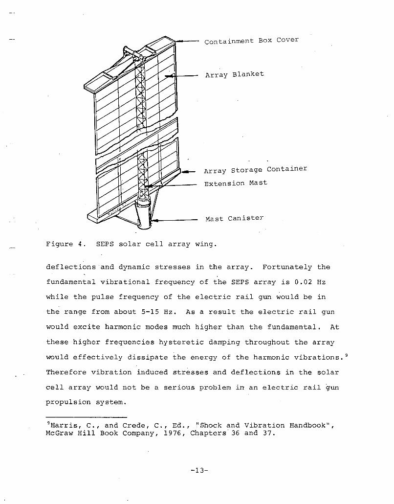
The SEPS type solar cell array power supply is a two-
winged configuration designed for in-orbit deployment from stowage.
Silicon solar cells with electrical interconnections attached to
a thin Kapton substrate form the solar cell blanket. This solar
cell blanket is stowed-during transport from earth to orbit by
rolling onto a mandrel or by folding into a box. In orbit the
solar cell array is deployed by a self extending truss-type mast.
A fold out version of one of these array wings is shown in Figure
4. In addition to the solar cells and the deployment mechanism
each wing includes bus strips, slip ring assembly, relays and other
hardware necessary to supply power to the spacecraft.
A SEPS type solar cell array would possess adequate
mechanical characteristics to make it compatible with an electric
rail gun propulsion system. An electric rail gun propulsion system
like an ion thruster system would provide low acceleration propul-
sion with concomitant low inertially induced stress on the array.
The pulsed load operation of the electric rail gun would excite
harmonic vibrations of the solar cell array. Excitation of the
fundamental or low harmonics would result in unacceptably high
7Hanley, G.M., "Evolution of- Satellite Power System (SPS) Concepts,"Report No. 78-9403, In Proceedings of the 13th Intersociety EnergyConversion Conference, August 20-25, 1978, San Diego, CA.
8Tonelli, A.D., and Nussberger, A.A., "The Design and Evaluationof a 5 GW Ga-AI-As Solar Power Satellite (SPS) ," Report No. 789404, In Proceedings of the 13th Intersociety Energy ConversionConference, August 20-25, 1978, San Diego, CA.
-12-
-
containment Box Cover
Array Blanket
Array storage Container
Extension Mast
Mast Canister
Figure 4. SEPS solar cell array wing.
deflections and dynamic stresses in the array. Fortunately the
fundamental vibrational frequency of the SEPS array is 0.02 Hz
while the pulse frequency of the electric rail gun would be in
the range from about 5-15 Hz. As a result the electric rail gun
would excite harmonic modes much higher than the fundamental. At
these higher frequencies hysteretic damping throughout the array
would effectively dissipate the energy of the harmonic vibrations. 9
Therefore vibration induced stresses and deflections in the solar
cell array would not be a serious problem in an electric rail gun
propulsion system.
9Harr is, C., and Crede, C., Ed., "Shock and Vibration Handbook II ,
McGraw Hill Book Company, 1976, Chapters 36 and 37.
-13-

The mass of a solar cell array is linearly related
to output power by a constant of proportionality.called thespeci
fic mass. In this study we used a specific mass of 13.5 kg/kWe
for the SEPS solar cell array. The equation relating power supply
mass, Mps ' to array output power, P, may therefore be written as
M = O.0135Pps (1 )
Equation (1) was used to define power ~upply mass for the system
and mission analyses. The same value was used for both the ion
thruster propulsion system and the electric rail gun propulsion
system.
2.2.2 The Rail Gun Thruster
In this section we examine the efficiency, mass and
configuration of an electric rail gun for a propulsion system.
The efficiency with which the electric rail gun converts ·electric
energy to kinetic energy directly effects the size of all other
subsystems and therefore is the primary determinant of system per
formance. The analytical study of single stage inductively driven
rail guns described in Reference 1 was extended to the smaller
size range under investigation herein.
2.?~.1 Rail Gun Efficiency
The analysis of rail gun performance was begun
by performing an energy balance on the electric rail gun circuit,
to determine energy partitioning during a single pellet launch
or cycle. The rail gun cycle is defined as the sequence of events
beginning with drive inductor current charging and including;
-14-
discharging the inductive energy into the rail gun; and accelerating
the pellet. The cycle ends when the drive inductor is again ready
for recharging. The rail gun cycle efficiency, na , is defined
as the ratio of pellet kinetic energy (at exhaust velocity) to
the sum of the kinetic energy plus energy losses. The pellet kin
etic energy, Eke' is described by the familiar relationship
(2)
where, m, is the pellet or projectile mass, and v, is pellet exhaust
velocity from the gun. The cycle energy losses may be described
by referring to Figure 5. Energy losses during a cycle arise from
two sources: resistive energy losses occur during drive inductor
charging and during pellet acceleration; and residual magnetic
energy stored in the inductor and accelerator at the end of a cycle
was assumed to be entirely lost.
Resistive losses during a cycle arise from circuit
resistance and rail gun resistance. As shown in Figure 5, a cir
cuit resistance, Ro ' was modelled as a lumped resistance character
istic of the inductor and connecting bus. The resistance of the
rail gun, Rr , was modelled as a varying resistance related to the
pellet motion along the gun. The rail resistance also included
the "velocity skin effect" wl).ich tends to confine current to a
thin sheet on the rail surface and significantly increases effect
ive rail resistance. 4
The magnetic losses at the end of a launch cycle result
-15-

x
IL,R r
Figure 5. Inductively driven rail gun simulation circuit.
from incomplete magnetic flux expansion. Magnetic flux remains
stored in both the drive inducto~ and the rail gun if current is
still flowing in the rail gun circuit as the pellet exits the gun
muzzle. If nothing is done to recapture this magnetic energy some
of it will be converted to ohmic heating of the rails and a large
fraction would be dissipated in an arc at the accelerator muzzle.
Conceivably some of the residual magnetic energy could be recaptured
~y. appropriate current clamping and other techniques. However
for this analysis we assumed that the residual magnetic energy
was an energy loss.
A mathematical model of rail gun pellet acceleration
was developed which included the energy loss mechanisms just identi-
fied. The modelling resulted.in a system of differential equations.
-16-
These equations were solved incrementally in a time stepped fashion
using fin~te difference techniques and a digital computer. The
rail gun analysis enabled us to identify and analyze the parameters
which affect rail gun efficiency.
Strategies were sought which would either maximize
efficiency or, due to physical limitations, would lead to constrain
ing conditions for each parameter. The seven major variables which
eftect efficien~y a~e identified and the effect of each variable
on rail gun efficiency is shown in Table 2. In addition, Table
2 also shows the implications of the optimizing or constraining
conditions applied to each variable. Finally, the value of each
parameter derived and used in the rail gun efficiency model is
listed.
When all the possible optimization values of the parame
ters shown in Table 2 are applied we find that rail gun efficiency
remains a function of two free independent variables, pellet exhaust
velocity and rail gun bore size (pellet mass). Optimal values
cannot be specified for these two parameters independent of mission
requirements. To develop an analytical expression relating rail
gun efficiency to these two independent parameters, we therefore
conducted simulations using the computer model of rail gun effici
ency and computed the efficiency for accelerators with the constraints
specified in T~ble 2. The efficiency was calculated for pellets
ranging in mass from 0.002 g - 2 g (corresponding to rail gun bore
sizes ranging from 1 rom - 10 rom) and for pellet exhaust velocities
ranging from 5 km/s to 20 km/s. Based on the data obtained from
these efficiency simulations we found that rail gun efficiency
-17-
TA!LE 2. PARAMETERS EFFECTING RAIL GUN EFFICIENCY
PARMIETER INCREASING EFFI- OPTIMIZING PHYSICAL VALUE OFCIENCY RESULTS. VALUE OR IMPLICATIONS PARAMETERSFROM INCREASING/ PHYSICALLY USED ORDECREASING MAG- IMPOSED DERIVEDNlTUDE OF PARA- CONSTRAINTMETER
RAIL GUN INCREASING OPTIMUM RAIL GUNS WITH SQUARE L' = 0.63 ILH/MINDUCTANCE !ORE ARE OPTIMAL, *PER UNITLENGTH
RAIL GUN INCREASING OPTIMUM PRACTICAL OPTIMUM X = 45.6 X10⁻⁶HV2LENGTH LENGTH, X, IS A FUNC-
TION OF !ORE SIZE ANDEXHAUST VELOCITY FORGIVEN VALUE~ OF OTHERPARAMET'ERS, *
RAIL TEM- DECREASING CONSTRAINED TRADEOFFS REQUIRED, T = 450'KPERATURE TO O!TAIN PRACTICAL
WASTE HEAT RADIATORSIZE AND ADEQUATESTRENGTH RAILS WITHACCEPTA!LE RESISTIV-ITY.
RAIL GUN INCREASING CONSTRAINED SPECIFIED BY MISSION 0.1 CM < H < 1.0 CMBORE SIZE REQUIREMENTS.
PELLET Ex- DECREASING CONSTRAINED SPECIFIED !Y MISSION 5 KM/S < V< 20 KM/SHAUST VEL- REQUIREMENTS. BOUNDSOCITY WERE IMPOSED.
PELLET Ac- INCREASING CONSTRAINED ACCELERATING STRESS 00 = 200 MN/M2
CELERATI NG LIMITED TO MAXIMUMSTRESS ALLOWABLE STRESS IN
PELLET.***
PELLET AREAL DECREASING CONSTRAINED BOTH PELLET DENSITY, P = 3000 KG/M3DENSITY p, AND PELLET LENGTH, D = HI2
D, SHOULD !E MINI-MIZED. PRACTICALPELLET DENSITY CHOSEN.PELLET LENGTH IN DI-RECTION OF TRAVELMUST BE LONGER THANONE-HALF THE BORESIZE, TO PREVENT IN-BORE PELLET TUM!LING.*
*THE COMBINATION OF A SQUARE !ORE AND PELLET LENGTH EQUAL TO ONE-HALF THE BORE SIZE ALLOWS THE PELLET MASSTO !E RELATED DIRECTLY TO BORE SIZE (I.E., M = pH3/2 = 1500H3), GIVEN THE PELLET DENSITY, PELLET MASS ANDBORE SIZE MAY !E USED INTERCHANGEABLY.
**A PRACTICAL OPTI~\UM CHARACTERISTIC PELLET ACCELERATION TIME IS THEREFORE IMPLIED AND. WAS FOUND TO CORRELATE TO RAIL HEIGHT AND EXHAUST VELOCITY AS, TA = 51 X iO~6HV,
***THE COM!INATION OF A DEFINED OPTIMAL RAIL INDUCTANCE, L', AND A DEFINED ALLOWA!LE STRESS, 00, DEFINES THEPEAK RAIL GUN CURRENT, 10, AS GIVEN BY, 10 = (200/L,)1/2H =2.52 X 10⁷H.
-18-
correlated to a power law relationship as given by
(3 )
The rail gun simulation data correlated to Equation 3 to better
than 5% over the entire range of pellet mass and exhaust velocity.
The predicted rail gun efficiency as a function of pellet mass
and pellet exhaust velocity is illustrated in Figure 6. Figure
6 shows that efficiency increases as pellet mass (bore size) in
creases. Efficiency decreases as pellet exhaust velocity increases.
Data from Reference 1 are also shown in Figure 6 to show that increas
ing rail gun bore size (higher pellet mass) increases efficiency.
From Figure 6 we see that rail gun efficiency will range from 20%
to 45% for pellets with mass of interest in this study.
2.2.2.2 Rail Gun Mass
Rail gun mass was estimated based on a geo
metrical· configuration which satisfies the imposed requirements.
The overall rail gun bore size and length are optimally chosen
to provide maximum efficiency. The thickness of the current con
ducting rails must be chosen to carry the high currents. The struc
ture which surrounds the rails must be chosen to have adequate
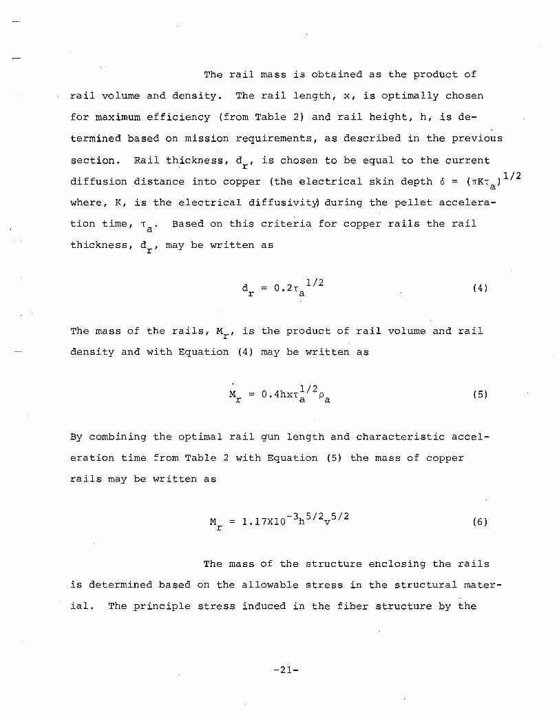
strength to withstand magnetic bursting forces on the rails. A
rail gun barrel concept which satisfies these requirements is shown
in Figure 7. It consists of a pair of rectangular cross-section
copper rails enclosed in a high strength, fiber reinforced com
posite structure. The mass of the rail gun barrel was computed
as the sum of the mass of the rails and the enclosing structure.
-19-

.- SYSTEM POWER: 25-100 KWE
EQN 3
SYSTEM POWER: 100-3000 KW 1E
60
50
.......... 40~........
>-u 30zUJ.....U
u.. 20u..w
10
010-3 10-2
1 10
10 KM/S
20 KM/S
Figure 6.
PELLET MASS (G)
Electric rail ~un cycle efficiency.
STRUCTUREJ__~--+--~_
\)"
......~------I;;",........ .-/
. I I "I
Figure 7. Rail gun cross section.
-20-
The rail mass is obtained as the product of
rail volume and density. The rail length, x, is optimally chosen
for maximum efficiency (from Table 2) and rail height, h, is de-
termined based on mission requirements, as described in the previous
section. Rail thickness, d , is chosen to be equal to the currentr
diffusion distance into copper (the electrical skin depth 0 = (TIKT )1/2a
where, K, is the electrical diffusivit~ during the pellet accelera-
tion time, Ta . Based on this criteria for copper rails the rail
thickness, dr' may be written as
(4 )
The mass of the rails, Mr , is the product of rail volume and rail
density and with Equation (4) may be written as
Mr
1/2= O.4hxT pa a (5)
By combining the optimal rail gun length and characteristic accel-
eration time from Table 2 with Equation (5) the mass of copper
rails may be written as
(6 )
The mass of the structure enclosing the rails
is determined based on the allowable stress in the structural mater-
ial. The principle stress induced in the fiber structure by the
-21-
magnetic bursting force on the rails would be tensile. The burst-
ing pressure on the rails is approximately one-half the accelerat-
ing pressure on the projectile. A fiber reinforced composite
material which could be used in the structure could safely support
tensile stresses up to 600 MN/m2 . By r~lating the stress in the
structure to the accelerating stress on the pellet we found that
the structural wall thickness, d , is related to the bore heights
by
d = 0.3hs (7)
The containment structure cross-sectional area was then computed
based on the design shown in Figure 7 and multiplied by the optimum
accelerator length, x, to obtain the volume. Assuming that the
average density of the fiber reinforced composite material is
2000 kg/m3 the· mass of the containment structure may be written
as
(8)
The total mass of the accelerator, Ma , is
obtained by summing the mass of the rails with the mass of the
structure. The total mass' may be written as a function of pellet
mass and exhaust velocity by recalling from Table 1 that pellet
mass may be written as a function of bore size (m = 1500 h 3) .
Combining Equations (6) and (8) we obtain;
-22-
(9 )
For most space applications the fineness
ratio of the accelerator (the ratio of accelerator length-to
containment structure diameter) would be very high, resulting
in unacceptable flexibility of the accelerator. In Section 2.2.5
we show that the rail gun could be integrated with the waste heat
radiator structure to provide adequate lateral stiffness.
2.2.3 Power Conditioning
The power conditioning system for the rail gun electric
propulsion system is comprised of all components required to elec
trically interface the photovoltaic power supply to the rail gun.
The overall purpose of power conditioning is to convert low voltage
average power from the solar cell array to high current, high
power pulses required by the rail gun for pellet acceleration.
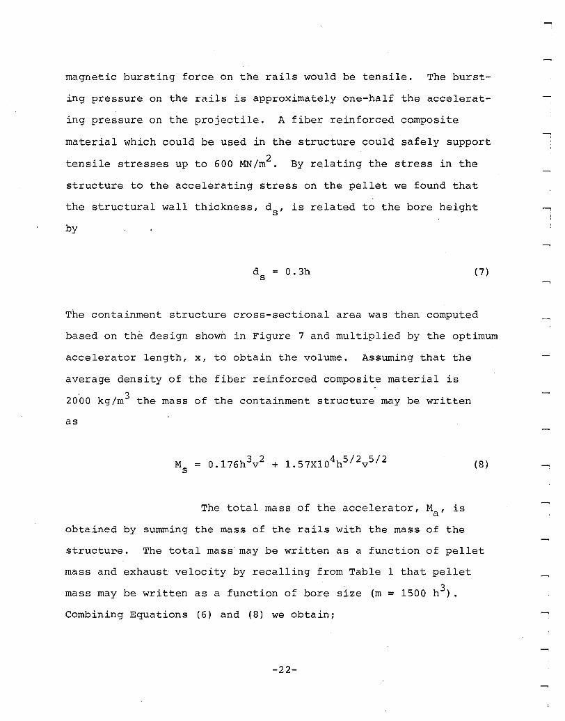
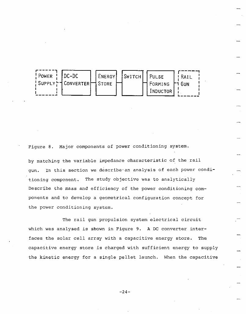
Several major components are required to perform power conditioning
as shown in Figure 8. The DC converter performs basically as
an impedance matching device, providing a constant impedance load
to the solar cells while providing constant power variable current,
variable voltage charging of the energy store. The energy store
provides the means of converting the low average power of the
solar cell array to high power pulses required by the rail gun
to accelerate pellets to high velocity. To enable repetitive
pulse operation of the rail gun switching elements cyclicly open
and close to permit energy store charging, followed by rapid dis
charge into the rail gun. Finally, a pulse forming inductor effi
ciently transfers the energy pulse ~o the rail gun at high current
-23-
r----...,: RAI L :
, GUN :I II .
I~------
r-----'I POWER II II SUPPLY l-I II II I-------
Figure 8.
DC-DC ENERGY SWITCH PULSE- CONVERTER - STORE - - FORMING -
INDUCTOR
Major components of power conditioning system.
by matching the variable impedance characteristic of the rail
gun. In this section we describe-an analysis of each power condi-
tioning component. The study objective was to analytically
Describe the mass and efficiency of the power conditioning com-
ponents and to develop a geometrical configuration concept for
the power conditioning system.
The rail gun propulsion system electrical circuit
which was analysed is shown in Figure 9. A DC converter inter-
faces the solar cell array with a capacitive energy store. The
capacitive energy store is charged with sufficient energy to supply
the kinetic energy for a single pellet launch. When the capacitive
-24-
ACCELERATOR
CLAMPDIODE
INDUCT07SWITC~
CAPACITOR
DC-DCCONVERTER
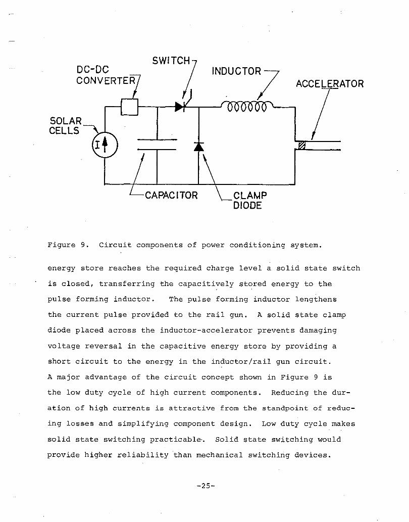
Figure 9. Circuit components of power conditioning system.
energy store reaches the required charge level a solid state switch
is closed, transferring the capacitively stored energy to the
pulse forming inductor. The pulse forming inductor lengthens
the current pulse provided to the rail gun. A solid state clamp
diode placed across the inductor-accelerator prevents damaging
voltage reversal in the capacitive energy store by providing a
short circuit to the energy in the inductor/rail gun circuit.
A major advantage of the circuit concept shown in Figure 9 is
the low duty cycle of high current components. Reducing the dur-
at ion of high currents is attractive from the standpoint of reduc-
ing losses and simplifying component design. Low duty cycle makes
solid state switching practicable-. Solid state switching would
provide higher reliability than mechanical switching devices.
-25-

In addition the capacitive based system concept shown in Figure
9 has lower mass than inductively stored energy concepts at the
energy storage levels required for the propulsion system investi-
gated.
2.2.3.1 DC Converter
A DC converter technology which appears attrac-
tive for application in an electric rail gun system is an actively
controlled series resonant inverter/converter. Series resonant
converters are under development for spaceborne electric ion pro-
pulsion applications and for aircraft application. Many of the
same features are required for the DC converter in an electric
rail gun propulsion system. 10 ,11,12
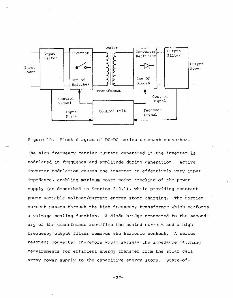
A simple block diagram of a series resonant
DC converter is shown in Figure 10. Electrical power enters the
converter through an input filter which isolates the source and
the converter from electrical transients. The input filter consists
primarily of diodes and capacitors. In the inverter two switch
pairs consisting of thyristors and diodes are used to close and
open in alternating succession two series resonant circuits of
capacitors and inductors and the primary winding of the transformer.
lO Biess, J., Inouie, J., and Schoenfeld, A., "Thyristor PowerProcessor for the 30 cm Mercury Electric Propulsion Engine," AIMPaper 75-433, 1975
IlHansen, I., "Description of a 2.2 kW Power Transformer for SpaceApplication," NASA Technical Memorandum 79138, NASA-Lewis ResearchCenter, 1979.
12Schwarz, F., "A 10 kW Lightweight DC Converter (Technology Feasibility Study for Lightweight Megawatt Range Converters)," AFAPLTR-77-45, Air Force Aero Propulsion Laboratory, Wright-PattersonAFB, 1977.
-26-
Scaler
- - Inverter Converter - Output -Input~ >- Rectifier Filter
Filter~ >-
/0- ~~ -{)t- Out
ut >- Poer ~ >-
ol >-Set of ... >- Set Of
Switches ~ ~ Diodes f---- I-- ~
• Transformer 4
ControlControl
SignalSignal
Input Control unit Feedback
Signal Signal-
P\ltInp werPow
Figure 10. Block diagram of DC-DC series resonant converter.
The high frequency carrier current generated in the inverter is
modulated in frequency and amplitude during generation. Active
inverter modulation causes the inverter to effectively vary input
impedance, enabling maximum power point tracking of the power
supply (as described in Section 2.2.1), while providing constant
power variable voltage/current energy store charging. The carrier
current passes through the high frequency transformer which performs
a voltage scaling function. A diode bridge connected to the second-
ary of the transformer rectifies the scaled current and a high
frequency output filter removes the harmonic content. A series
resonant converter therefore would satisfy the impedance matching
requirements for e£ficient energy transfer from the solar cell
array power supply to the capacitive energy store. State-of-
-27-
the-art converters with high internal operating frequencies (10-
30 kHz) would satisfy low mass, high efficiency requirements of
an electric rail gun converter.
Based on series resonant inverter designs for ion
thrusters, Reference 13 presents results of a parametric evaluation
which showed that DC converter mas·s, of state-of-the-art series
resonant converter designs is controlled by the converter power
input. DC converter mass, MDC ' was found to correlate to con
verter input, P, by a power series relationship, as given by
......,
( 9)
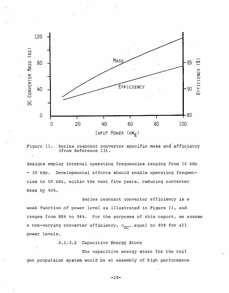
Based on Equation (9), Figure 11 illustrates that specific mass
of DC converters significantly decreases as power level rises.
Converter mass for power levels ranging from 25 to 100 kW , would. e
range from 49 to 117 kg respectively. We assume that the mass
predicted by Equation (9) adequately predicts the DC converter
mass for an electric rail gun propulsion system application.
High internal DC converter operating frequencies
lead to reduction in the mass of the transformer, and other reactive
components involved in the inversion and pulse modulation process.
The mass of the components is approximately proportional to the
inverse of the inverter frequency. Present resonant converter
13Byers, D., Terdan, F., and Meyers, I., "Primary Electric Propulsionfor Future Space Missions," NASA Technical Memorandum 79141, NASALewis Research Center, Cleveland, Ohio, 1979.
-28-
.....,
.....,
<.!J:::.::
........C/) 80 95 ~C/)
«:E >-
U0::: z:L.U L.UI-0::: UL.U> 40 90 u..z: u..0 WU
U0
120
0 85
0 20 40 60 80 100
INPUT POWER (KW E)
Figure 1I. Series resonant converter specific mass and effic,iency(from Reference 13) .
designs emp1oy'interna1 operating frequencies ranging from 10 kHz
- 30 kHz. Developmental efforts should enable operating frequen-
cies to 50 kHz, within the next five years, reducing converter
mass by 40%.
Series resonant converter efficiency is a
weak fun~tion of power level as illustrated in Figure 11, and
ranges from 88% to 94%. For the purposes of this report, we assume
a non-varying converter efficiency, nDC ' equal to 92% for all
power levels.
2.2.3.2 Capacitive' Energy Store
The capacitive energy store for the rail
gun propulsion system would be an assembly of high performance
-29-
capacitors configured to provide sufficient energy for a single
pellet launch at required voltage and current levels. Capacitor
energy storage density and therefore the capacitive energy store
mass is related to charge-discharge frequency, life and reliability
requirements, and voltage level. The requirements imposed on the
capacitive energy store by the rail gun propulsion system largely
determine the energy storage density of the capacitors.
The anticipated pulse frequency required of the capacitors
is about 10 Hz. The mission duration for an electric rail gun OTV
would be in the range from 30 days to 100 days. Assuming continuous
thrusting throughout the mission at a pulse repetition rate of 10
Hz the required capacitor life would be in the range from 10 7 to
10 8 pulses.
The ,combination of voltage and capacitance must be such that
the stored energy is adequate for the acceleration and that the
stored energy is transferred to the pulse forming inductor in a
time period short relative to the pellet launch time. Too slow
an energy transfer would reduce energy transfer and rail gun effici-
ency. Efficient performance is achieved if the capacitively stored
energy is transferred to the pulse forming inductor in less than
10% of the pellet launch time. 1 Applying this criteria the required
capacitor voltage, V , is given bys
v = lOnE /(1 L )s S 0 a (10)
where, Es ' is the stored energy, 10
, is the maximum rail gun cur
rent and, La' is the pellet acceleration time. For rail gun pro
pulsion systems with power levels in the 25 kWe to 100 kWe
range
-30-
the storage voltage specified by Equation (10) ranges from 1800
V to 2200 V.
Capacitors which meet the pulse frequency,
life and voltage level requirements specified in the previous para-
graphs have been developed and teste~ in conjunction with other
spaceborne electric propulsion programs. 14 The energy storage den-
sity of these capacitors is 90 J/kg. Assuming that these state-
of-the-art capacitors would be used in the rail gun propulsion
system, we can express capacitive energy store mass, MC' in terms
of the stored energy as
= O.OllE s (11)
The capacitors described in Reference 14 h~ve
a loss factor less than 0.011. At frequencies of a few Hz this
loss factor implies a capacitive energy store efficiency, nC ' of
97%. The energy storage efficiency is the ratio of the energy which
can be extracted in a single discharge to the energy initially stored.
2.2.3.3 Solid State Switch
The requirements imposed on the switch and
clamp shown in Figure 9 in the high current circuit, include peak
voltage standoff and high current conduction. As described in
the above paragraphs, the switch and the clamp must be capable
of standing off voltages in the range from 2 kV to 2.2 kV, or
specifically the voltage, Vs ' given by Equation (10). The peak
14Ramrus, A., "Development of a High Energy Density Capacitorfor Plasma Thrusters," Air Force Rocket Propulsion Laboratory,Report No. AFRPL-TR-80-35, October 1980.
-31-
current, 10
, which the switch must conduct was given in Section
2.2.2 and for the system under investigation may range from 50
kA to 150 kA. The duty cycle (the ratio of on time-to-off time)
for the high currents is only about 1.5%. This low duty cycle
combined with zero current switch opening implies that low mass,
highly reliable solid state switching would be possible.
Solid state switch and clamp elements combine
the attractive features of low mass and highly reliable, efficient
operation. In addition, solid state devices could be easily actu-
ated with small el~ctrical signals. References 15 and 16 describe
the specifications of off the shelf rugged thyristors and recti-
fiers which could be used in the rail gun circuit. Reference
15 describes the specifications for a fast switching thyristor
capable of standing off 2500 V and passing surge currents of up
to 13,000 A. The rectifier described in Reference 16 can stand
off 3000 V and can pass surge currents of up to 30,000 A. Each
of these units has a mass of about 0.95 kg. By suitable series-
parallel combinations of these units the required voltage standoff
and current conduction required in the rail gun propulsion power
conditioning system could be achieved. The number of parallel
strings required is obtained by dividing the peak current, I ,o
by the current capability of the solid state device. Similarly,
the number of series connected units in each parallel string is
15Westinghouse, Inc., Data Sheet for F~st Switching Thyristor,SCR-T9GH.
1 6 West inghouse , Inc., General Purpose Rectifiers Data Sheet, R920.
-32-
obtained by dividing the maximum capacitor voltage by the standoff
voltage capability of an individual device. The total number
of units required is obtained by multiplying the number of parallel
strings by the number of series connected elements in each string.
The mass of the switch array, M , is obtained by multiplyingsw
the total number of elements required by the mass per element,
and may be written as
M = 4.2lX10- 8V Isw s 0
In a similar manner the mass of the clamp diode array is given
by
(12 )
M~ = 1.33X10- 8V Is 0
(13 )
In both of these equations a multiplicative factor of 1.2 was
used to account for fault isolation fuses and support structure
mass. The thyristors described in Reference 15 have characteristics
which would permit each capacitor in the bank to be switched by
a single thyristor. Individual capacitor switching would enable
a desirable control on energy discharge level.
Since the functional forms of Equations (12)
and (13) are the same we can combine the switch mass and the clamp
diode mass to obtain one equation describing the total switch
system mass, Ms ' as
M = 5.54X10- 8V Is s 0
-33-
(14 )
Due to the low switch duty cycle we assumed that the switch losses
could be made negligible.
2.2.3.4 Pulse Forming Inductor
The pulse forming inductor in series with
the rail gun acts as a choke, lengthening fhe energy pulse provided
to the rail gun. During pellet launch the rail gun appears as
a variable impedance load. Impedance is proportional to pellet
velocity. A capacitive energy store discharged directly into
the rail gun would produce such a high current pulse at the begin-
ning of launch, that the pellet would be destroyed by the accel-
eration stresses. The inductor is, therefore, a p~lse forming
device which must be sized to momentarily store the entire energy
required for a launch. The required inductance, Lo ' may be re
lated to the stored energy, Es ' and to the peak "allowable current,
I , byo
:;;: 2E 112
s 0
A variety of coil geometries could be used
(15 )
to obtain the required inductance and stored energy. The minimum
mass geometry, a Brooks coil, is a thick solenoid with square
cross-section. The inductance (in MKS units) of a Brooks coil
is given by the relationship: 17
17Grover, F.W., Inductance Calculations--Working Formulas andTables, D. Van Nostrand Company, Inc., Copyright 1946.
-34-
where:
N = total number of turns
a = mean radius of the turns
(16)
By substituting Equation (15) into Equation (16).we could eliminate
L as a parameter and relate the coil dimension, a, to the numbero
of turns, N, in the coil. However, in doing so we still cannot
specify a unique coil. A unique design will result if the coil
satisfies two constraints: acceptable electrical losses; and
adequate mechanical strength. Since the coil carries current
for only a short period of time it can be made very efficient.
We imposed a constraint requiring that the coil efficiency be
at least 99%. High current coils containing a high magnetic flux
must have adequate strength to resist the induced bursting forces.
We chose to limit coil stresses to a conservative level equal
to 25 MN/m2 .
Imposing the constraint on inductor energy·
dissipation, implies a maximum allowable coil resistance which
is a function of the pellet launch time. By imposing this effi-
ciency constraint and requiring 99% coil efficiency, the coil
size is found to be
a =
-35-
(17)
where, p, is the conductor resistivity, and, s, is the coil pack-
ing factor. The coil mass is given by the product of average
coil density times coil volume. Recalling that the cross-section
of the windings of a Brook's coil is square, the coil mass, MLR ,
may be written as
(18)
where, d, is the average coil mass density (d = sdc + (l-d d i ) ,
dc' is the conductor mass density, and d i , is the insul~tion mass
density. Aluminum which combines the properties of low resistiv-
ity and low density is a good candidate inductor winding material.
We assumed the inductor is wound with aluminum conductor with a
-8'resistivity equal to 2.82X10 ~-m, and a density equal to 2,760
kg/m 3 . The coil packing factor, s, is a function of conductor
geometry, the voltage, and the dielectric material -used between
coil windings. We assumed that the packing factor is equal to
0.85. We assumed an insulation with density equal to 1,200 kg/m3 .
The mass of a Brook's geometry coil is a lower bound estimate
of the coil mass. To account for the additional mass (due to
support structure; non Brook's geometry and/or shield windings)
of an actual coil, we arbitrarily chose to estimate coil mass
by multiplying the minimum mass of a Brook's geometry by a factor
of two. Substituting for these constants in Equation (18) the
coil mass (based on the efficiency criteria) is given by
(19 )
-36-
The energy stored in an inductor may be thought
of as a two dimensional magnetic pressure which stresses the induc-
tor windings and/or coil former, much as fluid pressure stresses
the walls of a tank. For a given stored energy, as the size of
the coil is increased the magnetic pressure is decreased. Assuming
that .the magnetic flux is contained within a cylinder with radius
equal t~ a, and length equal t~ 2a/3 (Brook's coil), the size
of the coil, a, is related to the stored energy, E , and the coils .
stress, cry' by
a = [7E / (2 'IT cr )] 1/3s Y (20)
The mass of the coil may then be written as
(21 )
where, MLS ' is the coil mass which satisfies the coil strength
criteria. Substituting for the density, (i, (2,700 kg/m3 ), for
the coil stress, cr , (25 MN/m2 ) , and again using the multiplica-y
tive factor of two for the actual coil mass (as discussed in the
preceding paragraph), the coil mass may be written as
(22)
The mass of the pu·lse forming inductor will
be established based on either the resistance criterion or the
stress criterion and will always be given by the larger of the
-37-
values as calculated from Equation (19) or Equation (22). Using
the larger of, ~R and MLS guarantees that both the efficiency
criterion and resistance criterion are satisfied. For the 25 kWe
to 100 kWe propulsion systems under investigation in this study,
we found that the pulse forming inductor is always sized by the
resistance criterion and therefore the mass is given by Equation
(19) •
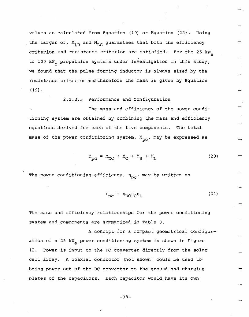
2.2.3.5 Performance and Configuration
The mass and efficiency of the power condi-
tioning system are obtained by combining ~he mass and efficiency
equations derived for each of the five components. The total
mass of the power conditioning system, Mpc ' may be expressed as
......,
(23)
The power conditioning efficiency, npc ' may be written as
(24)
The mass and efficiency relationships for the power conditioning
system and components are summarized ~n Table 3.
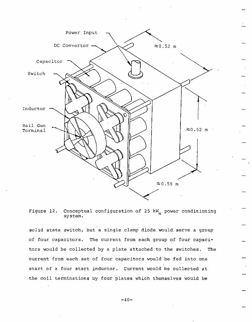
A concept for a compact geometrical configur-
ation of a 25 kW power conditioning system is shown in Figuree
12. Power is input to the DC converter directly from the solar
cell array. A coaxial conductor (not shown) could be used to·
bring power out of the DC converter to the ground and charging
plates of the capacit~rs. Each capacitor would have its own
-38-
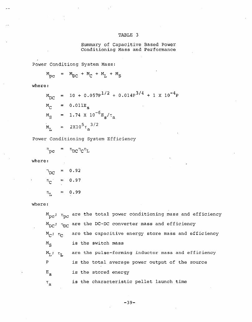
TABLE 3
Summary of Capacitive Based PowerConditioning Mass and Performance
Power Conditiong System Mass:
Mpc
where:
=
MDC = 10 + 0.057p 1 / 2 + 0.014p 3 / 4 + 1 X 10⁻⁴P
MC = 0.011E s
MS = 1. 74 X 10-6ES/L a
ML = 2XI0 5L
3/2a
Power Conditioning System Efficiency
npc = nDCnCnL
where:
nDC = 0.92
n . = 0.97C
nL = 0.99
where:
MpC ; npc are the total power conditioning mass and efficiency
MDC ; nDC are the DC-DC converter mass and efficiency
La
are the capacitive energy store mass and efficiency
is the switch mass
are the pulse-forming inductor mass and efficiency
is the total average power output of the source
is the stored energy
is the characteristic pellet launch time
-39-
Power Input
DC Converter
Capacitor
Switch
Inductor
Rail GunTerminal
~o. 52 m
~0.55 m
';::-0.52 m
Figure 12. Conceptual configuration of 25 kW power conditioningesystem.
solid state switch, but a single clamp diode would serve a group
of four capacitors. The current from each group of four capaci-
tors would be collected by a plate attached to the switches. The
current from each set of four capacitors would be fed into one
start of a four start inductor. Current would be collected at
the coil terminations by four plates which themselves would be
-40-
terminated on one rail of the gun. The other rail of the gun
would be connected to the capacitor ground plate by a conductor
coaxial with the inductor.
2.2.4 Propellant Handling System
This section describes our assessment of the propellant
handling system, required for the electric rail gun propulsion
concept under study. Our objective in this analysis was to first
identify and then to estimate the mass and performance of technically
feasible propellant handling system concepts. As used in this
study the propellant handling system includes all components required
to repetitively provide the rail gun with a pellet ready for launch.
The functions provided by the propellant handling system include:
propellant storage, from which a steady supply of pellet material
may be drawn; propellant transport, to a,pellet forming device
which may be physically removed from the propellant store; propellant
processing and pellet forming, which may be required to fabricate
gun sized pellets; and pellet loading into the rail gun bore.
Several requirements are imposed on the propellant
handling system in a rail gun propulsion system. The high pellet
accelerating stresses during launch require that the propellant
be a solid with considerable strength. The size of the pellet
must match the gun bore, which as described in section 2.2.2 will
range from 1 rom to 10 rom. The corresponding pellet masses range
from 2 mg to I g. The pellet shape must be a half cube, placed
in the bore'with the shortest dimension in the direction of pellet
motion. The pellets must be loaded into the gun at the launch
frequency which may range from 5 Hz to 15 Hz.
-41-

In the remainder of this section, we first identify
a number of propellant handling system concepts. Based on general
characteristics we select two of the identified concepts for de~
tailed analysis. We compare the two systems by comparing each
concept based on mass and performance estimates. Finally, we
briefly review pellet disposal problems and potential solutions
to these problems.
2.2.4.1 Propellant Handling System Options
A variety of means are available for accomp
lishing the ~our functions (i.e., storage, transport, pellet form
ing and pellet loading) of the propellant handling system.. These
four functions provide a convenient means of classifying and de
scribing the various options as shown in Table 4. A major dif
ferentiation may be done based on whether the propellant is stored
and transported in the fluid state or in the solid state. Sub
differentiations are based primarily on pellet forming technique.
Storage and transport of all propellants
stored in the fluid state would be accomplished via pressurized
tanks, pipes and valves. These storage and transport t~chniques
are well developed and could easily be adapted to the rail gun
propulsion system. All three fluid stored propellant concepts
could also essentially eliminate pellet loading as an independent
operation by forming the pellet directly in the gun bore. The
mechanism of phase change from fluid propellant to solid pellet
differentiates the fluid propellant concepts and the propellant
materials which would be used.
-42-
Table 4. Propellant Handling System Options
g~~fD FLUID SOLID
PURE PREFORM PREFORM PREFORM III LLETLIQUID + FILLER POLYMER + FILLER SLURRY PELLETS BAR SHEET
PROPELLANT -Tany. (5) -Tank Is) -Tank(s) -Tank/Hopper ...Pancake -Coiled on ---------STORAGE (with agit.tion) coils on Mandrel
Mandrel
PROPELLANT - Pipes jPressur ized -Pipes/Pressurized -Pipes /Pressur ized -Conveyor -Drive -Drive ---------TRANSPORT Tank!s)/ Tankls)/ Tank/ Ilolls Rolls
Valves Valves Valves
PELLET FORMING -Phase Change -Polymeriziltion -Extract Transport -Preformed -Parted -Slice Off -Extrude(Freezing) medium/ Off Bar Bar/Part Bar/Part
consolidate Off Pellet Off Pellet
PELLET LOADING -Fonned in 51 tu -Formed in Situ -Formed in Situ -Mechanical -Parted in -P.rted in -Parted inActuator Situ Situ Situ
ADVANTAGES -Easily stored and transported -No pellet -Integral -Integral -Storage-Handling technology well developed forming armature fuse easy
loading loading -Transport-Transport -Transport not required
and pellet imd pelletformation formationeasy easy
-Low power/ -Low power /low mass low mass
DISADVANTAGES -Storage tanks are massive (>0.01 mass of propellant) -Transport -Shear -Slicer -High pressure-Many active components (valves, pumps) and storage required required press/high-Requires -Pellet fo:nnation -Separation difficult -Shear rnassrefrigeration rate limited system -Pellet de- required -Separate
-Pellet strength -Requires two -High pressure gradation armaturelimi ted liquids consolidation -Separate loading
-Pellet formation -separ.te .rmature -Limited pellet armaturerate limited loading strength loading
-Separilte armature-,
-High powerloading required
-High power -Sepilrate armaturerequired lOilding
The pellet formation technique for the pure
liquid (or a pure liquid with an added filler for increased pellet
density) would be by thermal phase change or freezing. In the
second fluid propellant concept a monomer, or monomer and catalyst,
would be stored as a fluid and pellet formation would be achieved
by polymerization of the monomer to form a solid polymer. In
the slurry propellant concept, propellant particulates are held
suspended in a transport medium. Pellet formation would be achieved
by extracting the transport medium from the slurry and consolidating
the resultant particulates into a pellet.
-43-
The advantages and disadvantages of the three
fluid propellant concepts are similar, as shown in Table 4. The
advantages are found in the ease of propellant storage and trans
port via existing technology. The disadvantages include storage
tanks which are relatively massive relative to the stored propel
lant mass (greater than 1%) and many active components. Another
disadvantage is the limited pellet strength which could be obtained.
All three fluid propellant concepts would also require the compli
cating feature that the driving 'armature would require separate
loading behind the pellet. Relatively high power would probably
be required to operate the refrigeration unit for the pure liquid
phase. change and high power for the slurry consolidation might
also be required. Finally, the polymer fluid propellant concept
has the disadvantage of requiring separate storage and transport
systems for th8 monomer and the catalyst.
The solid propellant storage concepts are
primarily differentiated by the degree to which the pellet is
preformed before being placed aboard the spacecraft. Each of
the degrees of preforming imposes somewhat different requirements
on the handling functions and only few advantages and disadvan
tages are common to all.
Preformed pellets have all three dimensions
length, width and height, preformed. The pellets would have to
be stored in a tank and the transport would be via a conveyor
or pressurized pipe system. The pellet loading system would be
relatively complex requiring precision mechanical actuators. The
-44-

preformed bar would have two dimensions, say length and width
preformed to bore dimensions. Bars would be stored by winding
them onto coils and loading the coils onto a mandrel. The propel
lant transport would then be accomplished by unwinding the coiled
bar through guides and drive rolls. Pellets would be formed by
shearing a pellet of correct length off the end of the bar. This
shearing could be done with the pellet in situ eliminating the
need for separate pellet loading. The preformed sheet would only
have one dimension, say pellet width, preformed. storage would
be accomplished again by coiling onto a mandrel. Drive rolls
and gui~es would again be used for transport. Pellet forming
would be accomplished by first slicing bars off the sheet, then
shearing pellets off the bar in situ in the gun bore. Propellant
stored as a billet would first require extrusion into a bar fol
lowed by shearing of the bar into pellets in situ in the gun bore.
The solid propellant concepts share the ad
vantages of freedom of material selection to obtain adequate pellet
strength, low power requirements (excepting the billet) and low
mass storage and transport (excepting possibly the preformed pellets) .
The preformed pellets have the major advantage of no pellet forming
onboard the spacecraft. However this is obtained at the cost of
increased storage and transport difficulty. The preformed bar and
the preformed sheet share the advantages of enabling integral arma
ture/fuse attachment to the preformed bar or preformed sheet. Stor
age and transport are relatively simple but mechanical shears and/
or slicers are required. The preformed billet makes storage rela
tively easy but a high pressure, high mass press would be required
-45-
to form the bar and separate armature loading would be required.
Based on the advantages and disadvantages
outlined in Table 3, we chose the pure liquid fluid propellant
concept and the preformed bar solid propellant concept for further
analysis. Our logic for this selection was that the pure liquid
fluid propellant concept would provide representative data on
the characteristics of all fluid based concepts and that the anal
ysis for the pure. liquid concept would be more tractible. The pre
formed bar solid fuel propellant was selected as representing an
optimum balance between pellet loading complexity and pellet form
ing complexity.
2.2.4.2 Mass and Performance
The mass and performance of. the p~re liquid
fluid propellant and the preform~d bar solid propellant fuel hand
ling concepts were estimated by examining each of the four functions
or subsystems. The analyses are briefly described in the following
paragraphs in the order; storage, transport, pellet forming, and
pellet loading. Analytical expressions describing the mass of
these alternatives fuel handling systems is then assembled.
We estimated the mass of a tank containing
the fluid propellant by assuming a spherical tank. By forming
the ratio of the volume of material and the tank wall to the vol
ume enclosed by the tank and multiplying by the density of the tank
material and the density of the propellant the ratio of tank mass,
Mt ; to propellant mass, Mf , may be written as
-46-
(25)
Where, Pt , is the tank pressure, Pt , is the tank material density,
a, is the stress in the wall material, and, Pf , is the propellant
density. We assumed a tank pressurization of 0.35 MN/m2 , a wall
stress of 100 MN/m2
, a tank wall density of 3,000 kg/m3 and a
propellant density of 1,000 kg/m3 . Substituting these values
into Equation (25) we obtain
(26)
Tank hardware, such as flanges, will increase the tank mass~to-
propellant ma~s. The tank mass to propellant mass ratio for an
actual system (the BIMOD ion thruster) ranges from 2% to 9%.18
The mandrel on which the preformed bar is
wound is the solid propellant element comparative to the tank
of the fluid propellant concept. To enable our comparison be-
tween the solid propellant concept and the fluid propellant con-
cept a ratio of the mandrel mass, Mm, to propellant mass was de
rived. We assumed that the outside diameter of the propellant
coil, Df , is much larger than the diameter of the mandrel, Dm
and the mass ratio was found to be
(27)
1eNASA-Lewis Research Center, "30-cm Ion Thrust Subsystem DesignManual," NASA Technical Memorandum 79191, June 1979.
-47-
where, Pm' is the effective average density of the mandrel .. We
assumed the mandrel would be a non-solid, stiffened structure
with an average effective density equal to 300 kg/m3 . We assumed
a solid propellant density equal to 3,000 kg/m3 and a ratio of
the mandrel diameter-to-propellant diameter equal to 0.1. The
mandrel mass-to-propellant mass ratio is then
(28)
Comparing Equation (26) with Equation (28) we see that the solid
propellant mandl;"el would be about 10% of the tank mass ·for a fluid
propellant store.
The transport ~ystem of pipes, valves, and
controls required for a fluid propellant system is very spacecraft
design dependent. To estimate fluid propellant transport mass
here we scaled the BIMOD ion thruster system design in Reference
18, based on mass flow rate. For a repetitively operated rail
gun, the fluid propellant transport mass, Mft , may be expressed
as
(29)
where, k l , is the specific mass of the BIMOD ion thruster propel
lant transport system (k l = 1.2X10⁵s ), m, is the mass of each pellet,
and, f, is the launch frequency. The fluid propellant transport
mass may then be written as
-48-
5Mft = 1.2X10 mf (30)
The mass ,of the solid propellant transport
was estimated based on the power required to unwind the preformed
bar off of the coil, propell it along a guide system and insert
it into the breech of the rail gun. We assumed that the pellets
are roughly cubical and that the transport mechanism must supply
peak power of at least ten times the average power required to
drive the preformed bar (due to the cyclical operation of the
rail gun). The solid bar transport mass, Mst ' may be written
in terms of an average axial driving stress, 0, in the bar, as
given by
(31)
where, k 2 , is the specific mass of drive motor and, Pp' is the
pellet density. The drive motor specific mass, k 2 , may be con
servatively estimated based on the specific mass of conventional
motors (0.01 kg/W to 0.02 kg/W) and was taken as 0.05 kg/W to
approximately account for other components in the system such
as drive rolls and guides. We assumed that the preformed .bar
is driven at a very high, and therefore conservative, value of
average stress equal to 100 MN/m2 . As before the density'of the
propellant is assumed to be 3,000 kg/m3 . Substituting these values
into Equation (31) the solid propellant transport mass may be
written as
-49-
(32)
Equation (32) predicts that the solid propellant transport will
be 10% as massive as a fluid transport as predicted by Equation
(30) •
Forming pellets from the pure liquid (water)
propellant is accomplished by freezing in the rail gun breech.
The pellet forming mass will be dominated by the refrigeration
system required to extract the propellant heat of fusion, Q. The
e,lectrical power input, Pr' to a refrigerator required to freeze
the propellant is given by
(33)
where, nr , is the refrigeration system efficiency. We assumed
that the refrigerator operates at 40% of Carnot efficiency, that
refrigeration takes place at 250 0 K, and that heat from the refri-
geration system is rejected at 400 0 K, the efficiency, nr , will
be approximately 67%. We assumed that the mass of the refrigera-
tion system including primary power supply and heat radiators
can be related to the electrical power input, P , 'at a specificr
mass of 20 kg/kW. The fluid propellant pellet forming mass,e
Mff , may then be written as
(34)
-50-
Pellet forming from the preformed bar solid
propellant is accomplished by shearing the pellet off the end
of the bar. A conceptual sketch showing the essential features
of this concept is illustrated in Figure 13. The preformed bar
would be forced between the rails by a set of drive rolls and
a pair of guides. With the end of the propellant bar fully in-
serted between the rails, a shear would cut the pellet to" the re-
quired size. To assure containment of the plasma at the beginning
of launch, the rail gun could be fired with the shear blade ex-
tended across the top of the rails.
SH[AR ---+-,
FUEL BAR
~-- SHOCKATTEIWATOR
FUSE
DRIVE ROLL
FUEL GUIDE
RAIL
~---'H-r--CUT LJ r~[
Figure 13. Solid propellant pellet former.
The average power, P , required to repetitivelys
shear pellets from the propellant bar may be written as
-51-
P = Tmf/ps p (35 )
where, T, is the propellant shear strength. We have assumed that
the propellant is cubical. We assume that the propellant shear
strength is equal to 100 MN/M2 , and that pellet density is 3,000
kg/m3 . We also assumed that the mass of the pellet forming system
is linearly related to the shear power, P s ' by the constant speci
fic mass of 0.02 kg/We to account for the power supply and waste
heat radiator required to operate the shear (the specific mass
of the shear itself is therefore 0.08 kg/We). The mass of the
solid propellant pellet former system is obtained by substituting
for the constants in Equation (35) and multiplying by the 'specific
mass to obtain
(36)
Pellet loading is accomplished simultaneously
with the pellet forming function in-situ in the bore of the rail
gun for both the fluid and solid propellant concepts. No additional
mass is therefore identified for the pellet loading function.
The total mass, MI , of the propellant handling
system is obtained by summing the mass of each of the individual.
components associated with propellant storage, transport, and
pellet forming. The mass of the fluid propellant handling system
is given by
-52-
-2 5= l.6XlO Mf + l.3XlO mf
Mass of the preformed bar solid propellant handling system is
given by
(37)
(38)
We can see that the mass, Ml , of the propellant handling system
is a function of the total stored propellant mass at the beginning
of a mission, pellet mass, and the launch frequency. The solid
propellant handling system has a lower mass over all ranges of
performance.
2.2.4.3 Pellet Disposal
Each. pellet in the exhaust stream from an
electric rail gun thruster would have akinetic energy ranging
from about 1 kJ to 20 kJ. Impact of anyone of these pellets
on other spacraft in near earth orbit poses a substantial hazard.
The probability of a pellet impact on another spacecraft would
be greatly increased if the pellets are inserted into stable earth
orbits. Repetitively operating the rail gun thruster as an OTV
could establish artificial meteoroid belts in which the probabil-
ity of impact on a spacecraft would be unacceptably high. It
is therefore apparent that the pellets cannot be permitted to
attain stable earth orbits.
We have identified two potential methods
which can be used to prevent pellet disposition in stable earth
-53-'

orbits. One approach is to control the pellet exhaust velocity
to prevent pellet disposition in stable earth orbits. The velo-
city would be controlled such that the pellet would either enter
the earth's atmosphere or leave earth orbit. The second approach
involves using pellets made of a material which would "decompose"
into a state harmless to other spacecraft. One material, for
example, might be water launched as ice and sublimed to harmless
water vapor after launch.
Final pellet orbital dispostion is a function
only Of pellet velocity with respect ot the earth's reference
frame. The "objective is to arrange for the pellet to intersect
the earth's surface at or before perigee or to escape earth orbit
at apogee. The pellet velocity and therefore orbital character-
istics in the earth's reference frame is the vector sum of the
spacecraft velocity in the earth's reference fr-ame and the pellet
launch velocity in the spacecraft reference frame. Assuming that
the spacecraft orbit remians nearly circular during the orbital
transfer, we examined the conditions underwhich pellet "safe"
disposal would be accomplished. 1
We examined the pellet disposal requirements
for the thrusting strategy which produces optimal mission perform-
ance (i.e., for coplaner orbital transfers, holding the thrust
vector tangent to the orbit is optimal; see Appendix A). Under
these conditions the pellet exhaust velocity relative to the space-
craft, v , which causes earth capture of the pellet may be writtenc
in terms of the ratio of the orbital radius from the center of
-54-
......,
the earth, r o ' to the radius of the earth, reo For the LEO to
GEO outbound transfer this velocity is given by
(39)
The pellet exhaust velocity, v e ' which causes the' pellet to escape
earth orbit during outbound transfer is given by
v e> 7742 (2 1 /2+1 ) (r /r ) 1/2
e 0
For the inbound transfer from GEO to LEO
(40)
the spacecraft orbit velocity and the pellet exhaust velocity
are in the same direction and therefore the pellet exhaust velocity,
vi' which will cause pellet escape is given by
v.~
> 7742 (2 1 /2_ 1 ) (r /r ) 1/2e 0
(41 )
Together Equtions (39)-(41) define regions of stable pellet orbit
as illustrated in Figure 14. During an outbound transfer the
exhaust velocity could be adjusted to prevent any pellets from
attaining stable orbits. During the inbound transfer, practically
all exhaust velocities of interest would result in pellets escap-
ing earth orbit. Figure 14 illustrates that controlling pellet
exhaust velocity is a feasible approach to prevent pellets from
attaining stable earth orbits.
Using a sublimable pellet material, such
as water ice, appears to be another alternative which could be
-55-
20.......Cf) EARTH ESCAPE..........:E::.::
>- 15I-.....U0-I STABLE PELLET ORBITSU.I>
FOR LEO-GEO TRANSFERI- 10Cf)
~
«:cXw
5 EARTH REENTRYI- STABLE PELLET ORBITSU.I-I
FOR GEO-LEO TRANSFER-IU.I0..
01 2 3 4 5 6
Figure 14. Exhaust velocities which result in pellet stable orbits.
used to prevent pellet impact on· other spacecraft. Solar radi-
ation would provide the sublimation energy. We performed a calcu-
lation to find the surface recession rate of a pellet subliming
in the solar flux. Assuming an 80% absorption, the surface reces-
sion of ice would be approximately 2 rom/hr. (The absorption could
in principle be controlled with dyes). This implies that for the
pellets of interest in this study (2, rom - 5 rom cubes) the pellet
would be totally sublimed in approximately 1 hour. For most altitudes
this would be less than the orbital 'period. Assuming that the
ice could be made strong enough to survive launch (which appears
feasible), this represents a second alternative for preventing
damaging pellet-spacecraft impact.
2.2.5 Waste Heat Rejection
In this section we examine the waste heat radiators
-56-
required to reject the propulsion system power losses appearing
as heat. The rail gun is the primary source of waste heat. This
analyses therefore, concentrates on rail gun radiators. The power
conditioning system is the other major source of waste heat and
th DC converter is the major contributor within the power condi-
tioning system. We assume that the waste heat radiators for
the BIMOD DC converters could also be used for the electric rail
gun propulsion system. 1e The objective of the analysis was to
determine the mass, and a feasible configuration for the waste
heat radiators required to reject rail gun losses. Before estimat-
ing mass we examine the effects of requirements imposed on the
radiator by operation with the electric rail gun in the space
environment.
2.2.5.1 Radiator Performance
Three factors which significantly effect
spaceborne radiator performance include: radiator operating tem-
perature; effective sink temperature; and life and reliability.
Spacecraft heat rejection by radiation is
governed by a fourth-power temperature dependence as derived from
Planck's equation and given by:
(42)
where w is the rejected thermal power per unit radiator surface
area (referred to as specific radiated power), a sb ' is the Stefan
Boltzmann constant (5.6 7XIO -8wrn-2 °K- 4 ) , E: , is the radiator sur-e
face emissivity, T, is the radiator surface temperature, and,
-57-

TO' is the effective temperature of" the sink. Equation (42) il
lustrates that spacecraft specific radiated power increases rapidly
as the difference between radiator rejection temperature, T, and
the effective'space sink temperature, To' increases. Heat rejec
tion temperature, T, is established by a tradeoff between improved
specific radiated power and higher rail gun ohmic losses" implied
by the higher rejection temperatures.
Due to its size, a rail gun radiator would
interchange radiant energy with all other sources/sinks in its
surroundings including the sun, earth, deep space and other space-
craft components (especially the solar cell array). The effective
sink temperatur~, To' (in Equation (42» is therefore a function
of radiator gebmetry, orientation, an6 the spectral properties
of the radiator surface. Sink temperature can be effectively
minimized by mini~izing the radiant flux absorbed by the radiator
surface. Minimizing flux absorption is accomplished by: config-
uring the radiator to minimize the radiant interchange with the
spacecraft (i. e., by orienting the radiator so that the minimum
practicable surface area can "see" the sola~ cell array); and
by employing radiator surface coatings with low solar absorptance
and high thermal emissivity. Effective sink temperature minimi-
zation is specific to overall spacecraft design. The effective
sink temperature, T , for several spacecraft designs for near0"
earth space missions with multikilowatt heat rejection requirements
-58-
ranges from 190 0 K to 230 o K. 19 ,20,21 For the rail gun propulsion
system we assume an effective sink temperature of 230 o K.
Meteoroid impact damage poses a severe threat
to radiators. Highly reliable, long radiator life neceisitates
that redundant radiator components be provided or that the radiator
be adequately protected. The meteoroids comprising the flux in. -12
the vicinity of the earth range in mass from 10 grams to 1
gram. The particle mass density is usually taken as 0.5 g/cm3
for all particle sizes. The average particle velocity is often
assumed to be 20 km/s. Particles with mass ranging from 10-6
grams to 1 gram have the greatest probability of damaging a radiator.
Smaller particles have insufficient kinetic energy to puncture
the radiator while larger particles are not sufficiently numerous
to have an appreciable encounter probability. Based on a general
meteoroid flux model developed by NASA,22 a radiator for a 50
kW rail gun OTV would have a probability approaching 1 of beinge
impacted by a meteoroid with mass 5X10⁻⁶ grams in a hundred day
mission, and would have a probability approaching 1 of being impacted
-5by a meteoroid with mass 3x10 grams in a three year life time.
1 9Leach, J., and Stalmach, D., "Optimum Design of Spacecraft Radiators for Large Capacity or Long Duration Mision Applications,"Paper No. 79-ENAs-10, American Society of Mechanical Engineers, 1979.
2 0Nelson, W., and Howell, H., "Orbital Service Module Thermal Control System Design," Paper No. 79-ENAs-22, American Society of Mechanical Engineers, 1979.
21 F ilippi, F., Nervegna, N., and Zarotti, G., "Modularity and Optimization in Fluid Loop Radiator "systems," Paper No. 79-ENAs-37, American Society of Mechanical Engineers, 1979.
22 We idner, D., "Space Environment Criteria Guidelines for Use inSpace Vehicle Development (1969) Revision)," NASA-TM X-53957,1969.
-59-
The radiator for the rail gun OTV must therefore, be designed
-5to survive impact by meteoroids with mass at least up to 5X10
grams.
Either one of two general design approaches
are used to protect against radiative failure due to meteoroid
impacts. Radiator component redundancy is used to reduce the
probability that meteoroid damage will cause complete radiator
failure. Redundancies of 100%-200% are usually required to obtain
radiator reliabilities greater than 99%.23 Radiators designed
with redundancy therefore, have a mass ranging from 2 to 3 times
the radiator mass required to reject design heat loads.
A second design approach used to reduce the
mass penalty of redundant systems is to use little or no redundancy
and to surround critical radiator components with a thin sacrificial
shell called a "meteoroid bumper." The bumper, physically spaced
several centimeters away from the protected radiator surface,
is designed to fragment and/or vaporize high velocity meteoroids.
The energy density of the debris plume of meteoroids which per-
forate the shield is sufficiently low to prevent damage of the
critical radiator component surfaces. As predicted from equations
in Reference 19, the radiator bumper thickness required to protect
a rail gun radiator against damage by meteoroids with mass of
aproximately 5X10- 5 grams ranges from 0.08 mm to 0.5 mm. While
23Wright, J., "optimization of Large Heat Pipe Radiators for LongLife Space Heat Rejection Systems," Paper No. 79-ENAs,-25, AmericanSociety of Mechanical Engineers, 1979.
-60-
meteoroid bumper design optimization is specific to the spacecraft
design, these bumper thicknesses imply that satisfactory rail
gun OTV radiator reliability can be obtained with a meteoroid.
bumper radiator design at much lower mass than with a redundant
component radiator design. The attractiveness of meteoroid bumper
design is however somewhat mitigated by the reduction in specific
radiated power caused by 'the meteoroid bumper.
For purposes of analyzing the effects of
a meteoroid bumper on radiator performance the meteoroid bumper
and the radiator surface are assumed to be two plain parallel
surfaces, thermally connected by radiative interchange as shown
in Figure 15. We assume that both surfaces of the meteoroid bumper
are at a constant temperature, T2 . The meteoroid bumper reflects
part of the radiation emitted. by the radiator surface and. absorbs
part. The absorbed radiation is then emitted to the surroundings
at an intermediate temperature between the radiator surface temperature
and the temperature of the surroundings. The effect of the meteoroid
bumper on overall radiant heat transport may be determined by
conservation of energy considerations at plane A and plane B.
An equivalent emissivity, E, for use in Equation (42) can then
be found. Assuming that the radiator surface and the inner and
outer surfaces of the meteoroid bumper have independent emissivities
of E1 , E2 , E 3 respectively, the equivalent emissivity of the radiator
meteoroid bumper combination may be written as
(43)
-61-
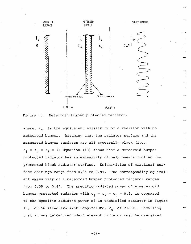
RADIATORSURFACE
METEROIDBUr~PER
SURROUNDINGS
T,2.
,
I,I
OUTER SURFACE
IPLANE B
IINNER SURFACE
IPLANE A
Figure 15. Meteoroid bumper protected radiator.
where, Ee , is the equivalent emissivity of a radiator with no
meteoroid bumper. Assuming that the radiator surface and the
meteoroid bumper surfaces are all spectrally black (i.e.,
E 1 = s2 = s3 = 1) Equation (43) shows that a meteoroid bumper
protected radiator has an emissivity of only one-half of an un-
protected black radiator surface. Emissivities of practical sur-
face coatings range from 0.85 to 0.95. The corresponding equiva1-
ent emissivity of a meteoroid bumper protected radiator ranges
from 0.39 to 0.44. The specific radiated power of a meteoroid
bumper protected radiator with sl = s2 = E3 = 0.9, is compared
to the specific radiated power of an unshielded radiator in Figure
16, for an effective sink temperature" To' of 230 o K. Recalling
that an unshielded redundant element radiator must be oversized
-62-......,
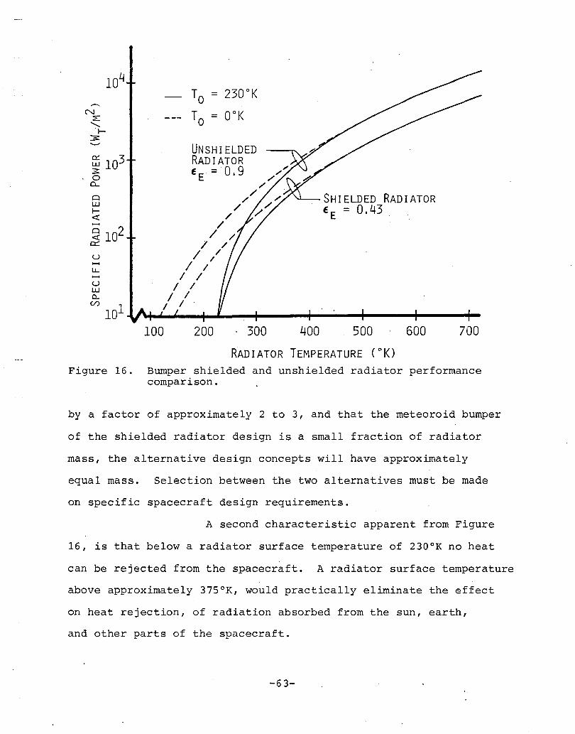
SH I ELDED RAD IATOREE = 0.43
TO = 230 0 K
TO = OOK
UNSHIELDED~ 103 RADIATOR3= EE = 0.9 ,/o /~ /
o /w /l- /<t /
~ 102 // /c::: I /u I /~ / //
/ /~ / /0.. / /c/), I I
lOJ. .v"+-.....J---+-....- ....----+----"4---~---...,..100 200 . 300 400 500 600 700
RADIATOR TEMPERATURE (~K)
Figure 16. Bumper shielded and unshielded radiator performancecomparison.
by a factor of approximately 2 to 3, and that the meteoroid bumper
of the shielded radiator design is a small fraction of radiator
mass, the alternative design concepts will have approximately
equal mass. Selection between the two alternatives must be made
on specific spacecraft design requirements.
A second characteristic apparent from Figure
16, is that below a radiator surface temperature of 230 0 K no heat
can be rejected from the spacecraft. A radiator surface temperature
above approximately 375°K, would practically eliminate the effect
on heat rejection, of radiation absorbed from the sun, earth,
and other parts of the spacecraft.
-63-
As illustrated in Figure 16, elevated temper-
ature heat rejection is desirable. Higher operating temperatures
however, increase rail gun resistive losses and decrease rail
mechanical strength due to thermal softening of the rails. Copper
alloys (for example, zirconium-copper) permit elevated temperature
(~6500K) rail gun operation with only modest increase in rail
resistivity and decrease in rail strength.2~ For this analysis,
we chose radiator/rail gun operating temperatures in the range
from 375°K to 450 o K. From Figure 16, the corresponding specific
radiated power for a shielded radiator ranges from 400 w/m2 to
with an. average specific radiated power equal to 625
For a 25 kt'le rail gun propulsion system at. 30% efficiency,
2the required radiatoi surface area is equal to 28 m .
900 w/m2
2W/m .
2.2.5.2 Radiator Mass and Configuration
Specific radiator system design and there-
fore radiator system mass is a function of the operating temper-
ature, life and reliability. Radiator system design may be cate-
gorized according to the method employed for thermal transport
from the heat source to the radiator. Heat pipe radiators are
passive, requiring no mechanical pumping for thermal transport.
Pumped fluid radiators on the other hand require a pump for active
thermal transport. Heat pipe radiators are inherently more reli-
able than pumped coolant systems. High source heat flux at mod-
erate temperature (less than 500 0K) such as found in the rail
2 ~ American Metal Climax, Inc., "AMZIRC, II AMAX Publication No.OF/66-279l, 1966.
-64-
gun usually requires a pumped coOlant system. New design concepts
propose hybrid radiators comprised of pumped coolant components
to remove heat from the source and transport it to the radiator
which is a heat pipe unit. The selection among heat pipe, pumped
coolant, and hybrid radiator systems appears to be spacecraft
dependent. Trade-off studies have shown that minimum radiator
system mass depends more on mission life and reliability require-
ments and overall spacecraft compatibility than radiator design
type. 19 - 22 '25 We assume that for the rail gun propulsion system
under study radiator life would be 2 to 3 years and 0.90 reliabil-
ity would be adequate (assuming an unmanned vehicle) .
The mass of conventional heat pipe, pumped
coolant, and hybrid radiator systems was approximated by relating
radiator system specific mass (i.e., mass per unit radiated power)
to a fourth power temperature relationship, for radiators with
similar life and reliability. Based on data in References 19,
20, 21, 22, 25, 26 and 27 we found that radiator specific mass,
ahr , can be related to radiator temperature, T, by
(44 )
25Alario, J. and Haslett, R., "Modular Heat Pipe Radiators for Enhanced Shuttle Mission Capabilities," Paper No. 79-ENAs-17, AmericanSociety of Mechanical Engineers, 1979.
26Ellis, W., "Radiator Heat Rejection Options for Shuttle Payloads,"Paper No. 79-ENAs-18, American Society of Mechanical Engineers,1~79.
27Koenig, D., Ranken, W., and Salmi, E., "Heat Pipe Reactors forSpace Power Applications," AIAA Paper No. 77-491, American Institute of Aeronautics and Astronautics, 1977.
-65-:-
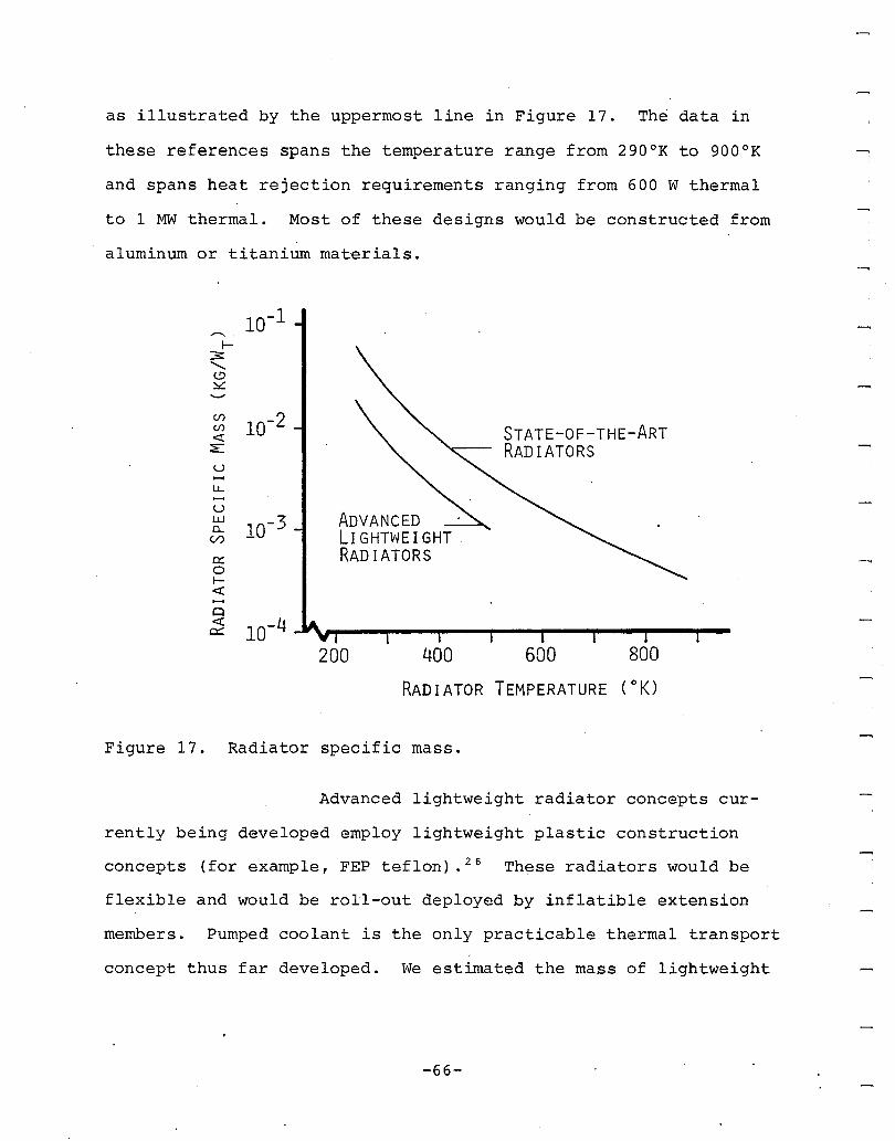
as illustrated by the uppermost line in Figure 17. The data in
these references spans the temperature range from 290 0 K to 900 0 K
and spans heat rejection requirements ranging from 600 W thermal
to 1 MW thermal. Most of these designs would be constructed from
aluminum or titanium materials.
(/)
10-2(/) STATE-OF-THE-ART«::E RADIATORSuLL
uADVANCEDw
10-3a.. Lr GHTWE I GHT .(/)
e::: RADIATORS0f-«-Cl« 10-40::::
200 400 600 800
RADIATOR TEMPERATURE ( 0 K)
Figure 17. Radiator specific mass.
Advanced lightweight radiator concepts cur-
rently being developed employ lightweight plastic construction
concepts (for example, FEP teflon) .26 These radiators would be
flexible and would be roll-out deployed by inflatible extension
members. Pumped coolant is the only practicable thermal transport
concept thus far developed. We estimated the mass of lightweight
-66-
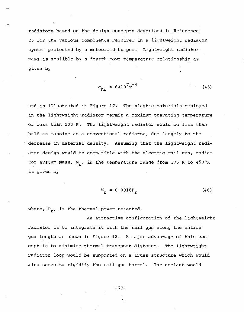
radiators based on the design concepts described in Reference
26 for the various components required in a lightweight radiator
system protected by a meteoroid bumper. Lightweight radiator
mass is scalible by a fourth powr temperature relationship as
given by
(45)
and is illustrated in Figure 17. The plastic materials employed
in the lightweight radiator permit a maximum operating temperature
of less than SOooK. The lightweight radiator would be less than
half as massive as a conventional radiator, due largely to the
decrease in material density. Assuming that the lightweight radi
ator design would be compatible with the electric rail gun, radia
tor system mass, Mr , in the temperature range from 37s o K to 4S0 0 K
is given by
(46)
where, Pr , is the thermal power rejected.
An attractive configuration of the lightweight
radiator is to integrate it with the rail gun along the entire
gun length as shown in Figure 18. A major advantage of this con
cept is to minimize thermal transport distance. The lightweight
radiator loop would be supported on a truss structure which would
also serve to rigidify the rail gun barrel. The coolant would
-67-
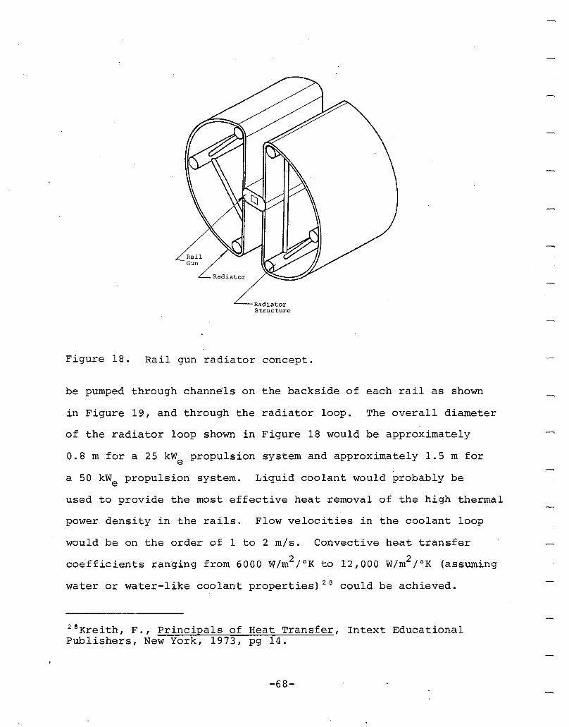
RadiatorStructure
Figure 18. Rail gun radiator concept.
be pumped through channels on the backside of each rail as shown
in Figure 19, and through the radiator loop. The overall diameter
of the radiator loop shown in Figure 18 would be approximately
0.8 m for a 25 kWe propulsion system and approximately 1.5 m for
a 50 kWe propulsion system. Liquid coolant would probably be
used to provide the most effective heat removal of the high thermal
power density in the rails. Flow velocities in the coolant loop
would be on the order of 1 to 2 mise Convective heat transfer
coefficients ranging from 6000 W/m2 /oK to 12,000 w/m2 /oK (assuming
water or water-like coolant properties) 28 could be achieved.
2eKreith, F., Principals of Heat Transfer, Intext EducationalPublishers, New York, 1973, pg 14.
-68-
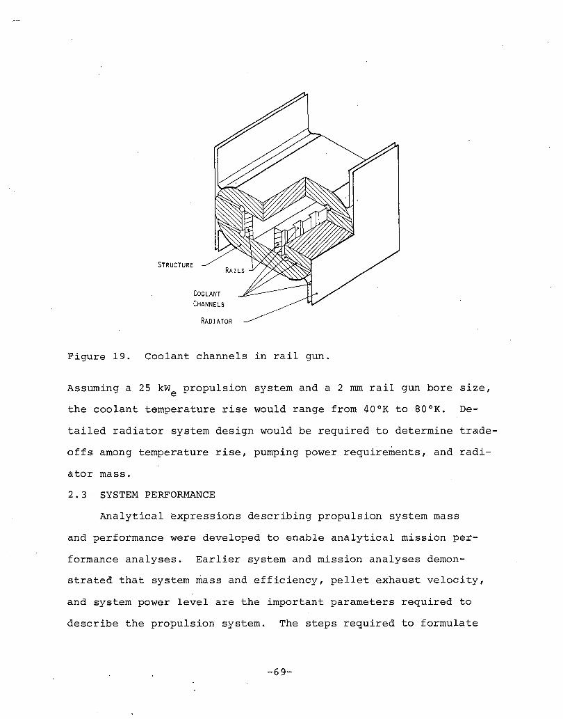
STRUCTURE
COOLANTCHANNELS
RADIATOR
Figure 19. Coolant channels in rail gun.
Assuming a 25 kWe propulsion system and a 2 rom rail gun bore size,
the coolant temperature rise would range from 40 0 K to BooK. De-
tailed radiator system design would be required to determine trade
offs among temperature rise, pumping power requirements, and radi-
ator mass.
2.3 SYSTEM PERFORMANCE
Analytical expressions describing propulsion system mass
and performance were developed to enable analytical mission per-
formance analyses. Earlier system and mission analyses demon-
strated that system mass and efficiency, pellet exhaust velocity,
and system power level are the important parameters required to
describe the propulsion system. The steps required to formulate
-69-
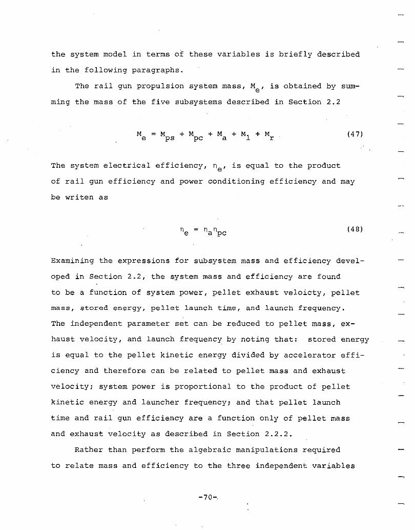
the system model in terms of these variables is briefly described
in the following paragraphs.
The rail gun propulsion system mass, M , is obtained by sume
ming the mass of the five subsystems described in Section 2.2
(47)
The system electrical efficiency, ne , is equal to the product
of rail gun efficiency and power conditioning efficiency and may
be writen as
(48)
Examining the expressions for subsystem mass and efficiency devel-
oped in Section 2.2, the system mass and efficiency are found
to be a function of system power, pellet exhaust veloicty, pellet
mass, stored energy, pellet launch time, and launch frequency.
The independent parameter set can be reduced to pellet mass, ex-
haust velocity, and launch frequency by noting that: stored energy
is equal to the pellet kinetic energy divided by accelerator effi-
ciency and therefore can be related to pellet mass and exhaust
velocity; system power is proportional to the product of pellet
kinetic energy and launcher frequency; and that pellet launch
time and rail gun efficiency are a function only of pellet mass
and exhaust velocity as described in Section 2.2.2.
Rather than perform the algebraic manipulations required
to relate mass and efficiency to the three independent variables
-70-.
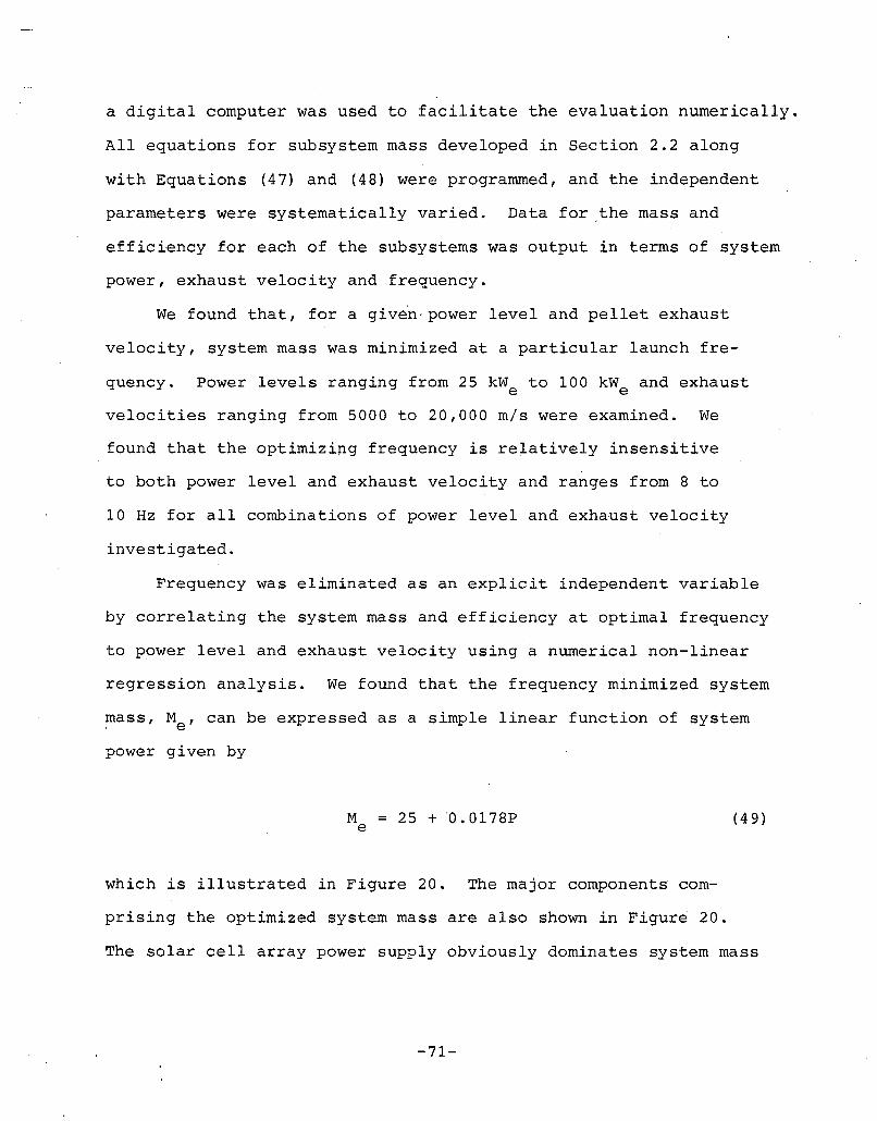
a digital computer was used to facilitate the evaluation numerically.
All equations for subsystem mass developed in Section 2.2 along
with Equations (47) and (48) were programmed, and the independent
parameters were systematically varied. Data for the mass and
efficiency for each of the subsystems was output in terms of system
power, exhaust velocity and frequency.
We found that, for a given' power level and pellet exhaust
velocity, system mass was minimized at a particular launch fre-
quency. Power levels ranging from 25 kWe to 100 kWe and exhaust
velocities ranging from 5000 to 20,000 mls were examined. We
found that the optimizing frequency is relatively insensitive
to both power level and exhaust velocity and ranges from 8 to
10 Hz for all combinations of power level and exhaust velocity
investigated.
Frequency was eliminated as an explicit independent variable
by correlating the system mass and efficiency at optimal frequency
to power level and exhaust velocity using a numerical non-linear
regression analysis. We found that the frequency minimized system
mass, Me' can be expressed as a simple linear function of system
power given by
M = 25 + ·0.0178Pe (49)
which is illustrated in Figure 20. The major components com
prising the optimized system mass are also shown in Figure 20.
The solar cell array power supply obviously dominates system mass
-71-
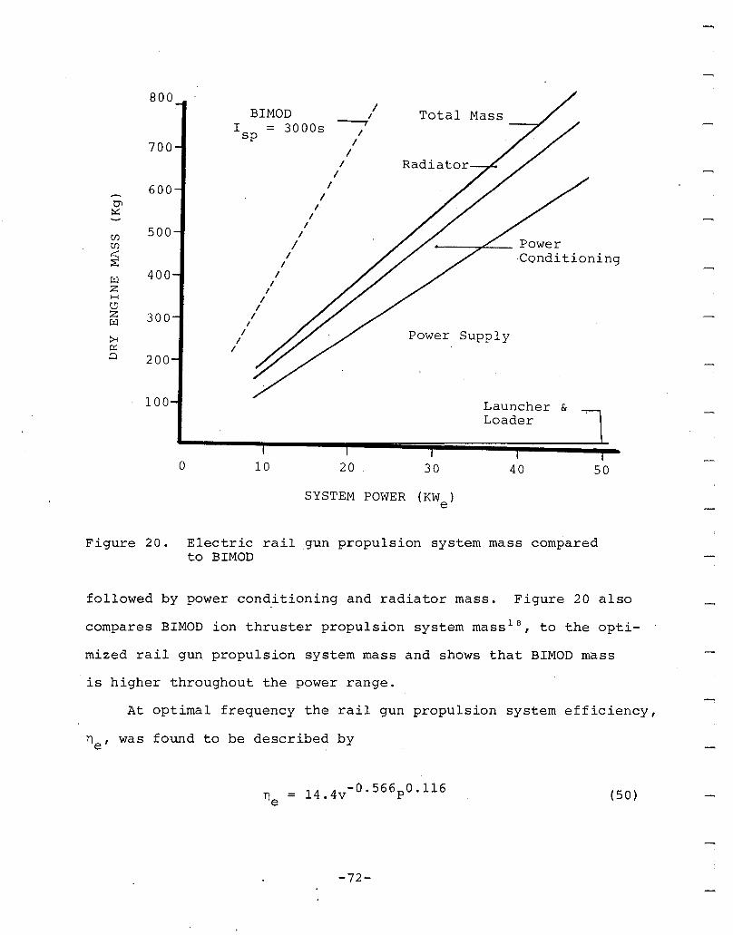
5040
Launcher &Loader
__~.e.-_ Power·Conditioning
30
Total Mass--'
Power Supply
Radiator
2010
BIMODI = 3000ssp
o
800
SYSTEM POWER (KW )e
Figure 20. Electric rail gun propulsion system mass comparedto BIMOD
followed by power conditioning and radiator mass. Figure 20 also
compares BIMOD ion thruster propulsion system mass l8, to the opti-
mized rail gun propulsion system mass and shows that BIMOD mass
is higher throughout the power range.
At optimal frequency the rail gun propulsion system efficiency,
ne , was found to be described by
(50)
-72-
which is illustrated in Figure 21. The inverse relationship of
rail gun system efficiency to pellet exhaust velocity (specific
impulse) contrasts with the direct proportionality relationship
between BIMOD system efficiency an~ specific impulse as shown
in Figure 21.
BIMOD I = 3000ssp
--
50
I = 2000ssp
= 1000s
4030
= 2000s
20
~_---I = 50 Ossp
BIMOD I sp
10
60
(j,o
>< 50uz~H 40uH~~
~ 30:8~
E-iU) 2><U)
1
0
0
SYSTEM POWER (KWe )
Figure 21. Electric rail gun propulsion system efficiency comparedto BIMOD
The expressions describing optimized rail gun propulsion
system mass and efficiency described by Equations (49) and (50),
were used to examine rail gun propulsion system OTV mission per-
formance. Pellet exhaust velocity was constrained in the range
from 5,000 mls to 20,000 mls and system power level was constrained
in the range from 25 kWe to 100 kWe .
-73-
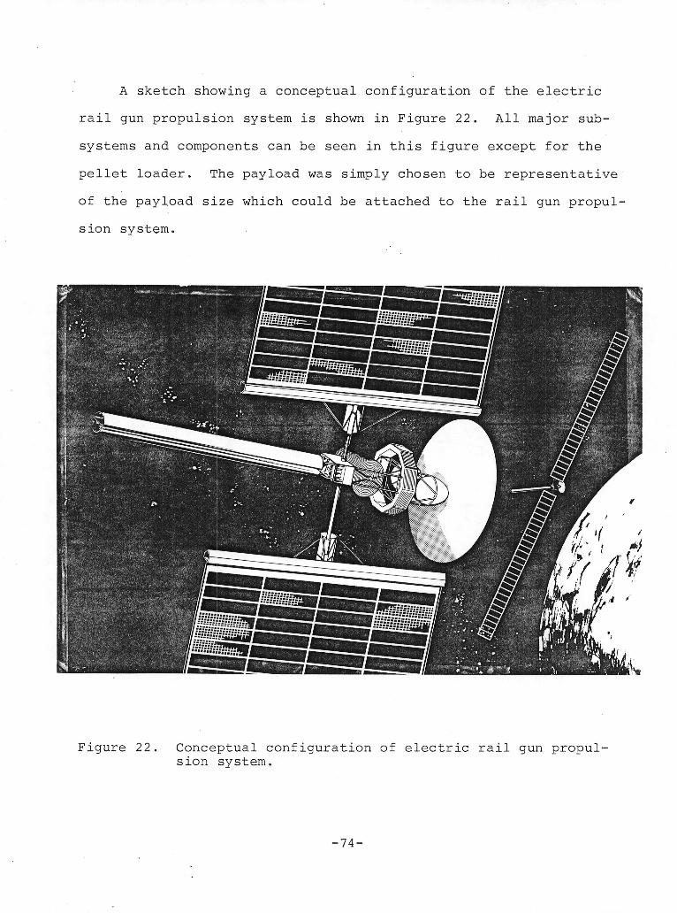
I
A sketch showing a conceptual configuration of the electric i
rail gun propulsion system is shown in Figure 22. All major sub- isystems and components can be seen in this figure except for the
pellet loader. The payload was simply chosen to be representative iof the payload size which could be attached to the rail gun propul-
sion system. I
iiIiI
o i
!!
Figure 22. Conceptual configuration of electric rail gun propul- Ision system.
i-74- i
I
Two areas of subsystem interaction can be identified by ob
.serving Figure 22. As discussed in Section 2.2.5 the waste heat
radiator integral with the rail gun cou~d operate at elevated
temperatures. During certain portions of every orbit the solar
cell array would be subjected to this elevated, temperature radia
tion. The amount of thermal radiation received and the effect
on the solar cell array is difficult to estimate at this point.
Elevated temperature self annealing solar cells (such as GaA1As
cells) may actually benefit from the thermal radiation. The elec
tro-magnetic radiation emitted due to the high current pulsing
of the pulse forming inductor may effect system electronics. This
effect is.difficult to evaluate, but must be considered in detailed
design. We feel that these subsystem interactions do not signifi
cantly effect system feasibility.
-75-

-76-
SECTION 3
MISSION ANALYSIS
The mission performance of an electric rail gun propulsion
system was analysed for coplaner payload transfer from low earth
orbit (LEO) to geosynchronous orbit (GEO). The mission examined
included payload transfer from LEO to GEO followed by the return
of the propulsion system to LEO for reuse. One way transfer from
LEO to GEO of the propulsion system and payload was examined.
The rail gun mission performance was compared to two alternative
orbital transfer propulsion devices; a 30 cm BIMOD ion thruster
propulsion system, and the inertial upper stage (IUS) chemical
propulsion unit. Mass was the single parameter used to.character
ize payloads. Payload masses of 1150 and 2300 kg were considered.
The mission performance of the electric propulsion s~stems
was analyzed based on low thrust, spiral-up orbital mechanics.
The IUS mission performance was analyzed based on the classical
two impulse Hohmann transfer. Electric rail gun system performance
characteristics used in the mission analysis were drived from
Equations (49) and (50). BIMOD system performance data were ob
tained from Reference 18. Two-staged IUS system performance data
was obtained from Reference 29.
The objective of the mission analyses was to establish the
conditions which minimize propulsion system initial mass in LEO
29NASA , "NASA Space Systems Technology Model," To Be Published
-77-
for a given LEO to GEO trip time and subject to power supply size
constraints. The assumptions in all cases included propulsion
system operation at the full available power of the power supply,
and constant exhaust velocity throughout the LEO to GEO transfer.
For the rail gun system, an optimization is required to find the
exhaust velocity which minimizes the initial propellant or system
mass. The 'approach in the mission analysis was therefore to select
a trip time and solve the orbital transfer equations to determine
the exhaust velocity which results in the lowest initial mass
or the lowest propellant mass. Mission analysis details are fully
described in Appendix A.
Due to the directly proportional relationship of BIMOD system
efficiency to exhaust velocity, there is no advantage in orbital
transfer missions to operate the ion thruster at less than the
maximum obtainable exhaust velocity. System mass and trip time
are therefore uniquely related with no optimization required.
The effect of solar shadowing on electric propulsion OTV
performance is included in all mission analyses as described in
Appendix A. The system mass and propellant mass requirements are
both increased by solar shadowing and these effects are included
in all the results presented in this report. The trip time is
also increased by solar shadowing (by ~25%), however, this effect
is not included in the results displayed (i.e., the trip times
assume continuous thrusting). The effect of solar cell array degra
dation due to charged particle bombardment in near earth space
could not be adequately handled by the analysis programs available.
Due to the high solar cell degradation, the numerical optimization
-78-
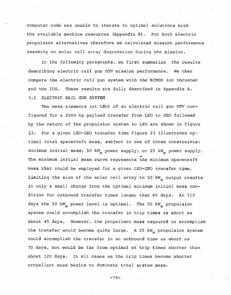
computer code was unable to iterate to optimal solutions with
the available machine resources (Appendix A). For both electric
propulsion alternatives therefore we calculated mission performance
assuming no· solar cell array degradation during the mission.
In the following paragraphs, we first summarize the results
describing electric rail gun OTV mission performance. We then
compare the electric rail gun system with the BIMOD ion thruster
and the IUS. These results are fully described in Appendix A.
3.1 ELECTRIC RAIL GUN SYSTEM
The mass elements (at LEO) of an electric· rail gun OTV con
figured for a 2300 kg payload transfer from LEO to GEO followed
by the return of the propulsion system to LEO are shown in Figure
23. For a given LEO-GEO transfer time Figure 23 illustrates op
timal total spacecraft mass, subject to one of three constraints:
minimum initial mass; 50 kWe power supply; or 25 kWe power supply.
The minimum initial mass curve represents the minimum spacecraft
mass that could be employed for a given LEO-GEO transfer time.
Limiting the size of the solar cell array to 50 kWe output results
in only a small change from the optimal minimum initial mass con
dition for outbound transfer times longer than 60 days. At 110
days the 50 kWe power level is optimal. The 50 kWe propulsion
system could accomplish the transfer in trip times as short as
about 45 days. However, the propellant mass required to accomplish
the transfer would become quite large. A 25 kWe propulsion system
could accomplish the transfer in an outbound time as short as
70 days, but would be far from optimal at trip times shorter than
about 120 days. In all cases as the trip times become shorter
propellant mass begins to d~minate total system mass.
-79-
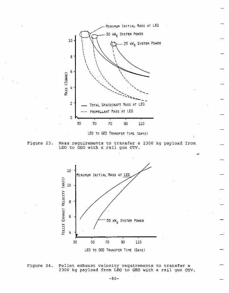
LEO TO GEO TRANSFER TIME (DAYS)
Figure 23. Mass requirements to transfer a 2300 kg payload fromLEO to GEO with a rail gun OTV.
12
(J)
"-~ 10
>~
uoiLl 8>~en:::l
:2 6xUJ
~UJ-l-l
cf 4
KW E SYSTEM POWER
30 50 70 90 110
LEO TO GEO TRANSFER TIME (DAYS)
Figure 24. Pellet exhaust velocity requirements to transfer a2300 kg payload from LEO to GEO with a rail gun OTV.
-80-
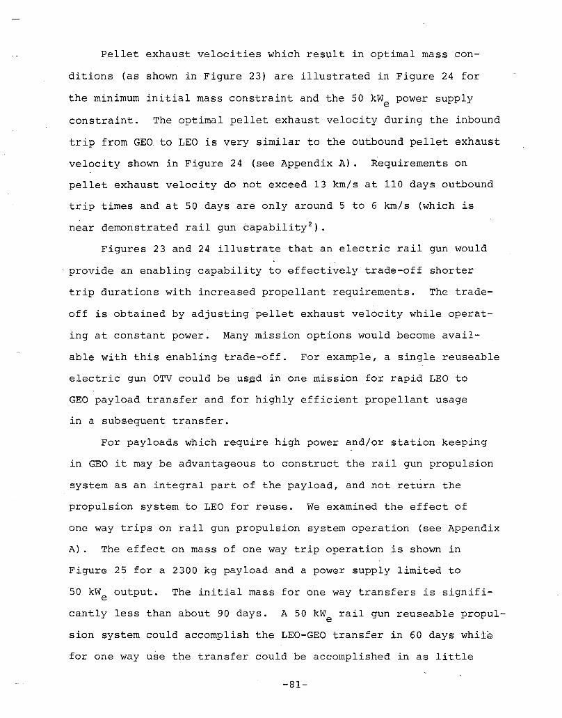
Pellet exhaust velocities which result in optimal mass con-
ditions (as shown in Figure 23) are illustrated in Figure 24 for
the minimum initial mass constraint and the 50 kWe power supply
constraint. The optimal pellet exhaust velocity during the inbound
trip from GEO to LEO is very similar to the outbound pellet exhaust
velocity shown in Figure 24 (see Appendix A). Requirements on
pellet exhaust velocity do not exceed 13 km/s at 110 days outbound
trip times and at 50 days are only around 5 to 6 km/s (which is
near demonstrated rail gun capability 2).
Figures 23 and 24 illustrate that an electric rail gun would
provide an enabling capability to effectively trade-off shorter
trip durations with increased propellant requirements. The trade-
off is obtained by adjusting pellet exhaust velocity while operat-
ing at constant power. Many mission options would become avail-
able with this enabling trade-off. For example, a single reuseable
electric gun OTV could be us~d in one mission for rapid LEO to
GEO payload transfer and for highly efficient propellant usage
in a subsequent transfer.
For payloads which require high power and/or station keeping
in GEO it may be advantageous to construct the rail gun propulsion
system as an integral part of the payload, and not return the
propulsion system to LEO for reuse. We examined the effect of
one way trips on rail gun propulsion system operation (see Appendix
A). The effect on mass of one way trip operation is shown in
Figure 25 for a 2300 kg payload and a rower supply limited to
50 kW output. The initial mass for one way transfers is signifie
cantly less than about 90 days. A 50 kW rail gun reuseable propule
sion system could accomplish the LEO-GEO transfer in 60 days while
for one way use the transfer could be accomplished in as little
-81-
10
8
UJZZ0I- 60UJ..J
I-<:: 4enen«::;::
2
50 KW E POWER SUPPLY
- TOTAL SPACECRAFT MASS
- -- PROPELLANT MASS
- ·-PAYLOAD MASS
ROUNDTRIP
ONEWAY
30 50 70 90 noLEO TO GEO TRANSFER TIME (DAYS)
Figure 25. Effect of reuseable verses one-way m~ss~6ns on railgun propulsion system mass requirements.
as 30 days. The advantage in mass of one way tran§fers increases
at lower trip times due to the reduction in propellant required.
The effect of payload mass scaling on propulsion system mass
is shown in Figure 26. Data from Reference 1 were used for the
larger payload masses. As illustrated the mass scales approximately
linearly. The apparent discontinuity between the results of
this study and those of Reference 1 arises from the much higher
solar cell array mass used in this study. (i.e., 13.5 kg/kWe
compared to 5 kg/kW ) .e
3.2 COMPARISON OF ALTERNATIVE PROPULSION SYSTEMS
Uniform comparison of performance among the electric rail
gun propulsion system, the BIMOD ion thruster system, and the
IUS chemical propulsion system requires that only one way LEO
-82-
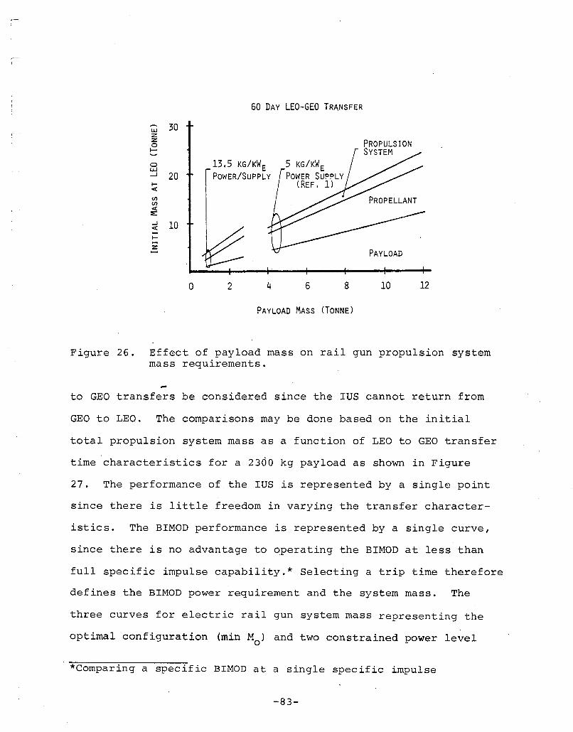
60 DAY LEO-GEO TRANSFER
1210
PAYLOAD
8642o
w 30zz0~
~ 13,5 KG/KW E 5 KG/KW EWJ-J 20 POWER/SUPPLY j"POWER SUPPLY~ (REF, 1)<ww<~
~ 10<~
z
PAYLOAD MASS (TONNE)
Figure 26. Effect of payload mass on rail gun propulsion systemmass requirements.
to GEO transfers be considered since the IUS cannot return from
GEO to LEO. The comparisons may be done based on the initial
total propulsion system mass as a function of LEO to GEO transfer
time characteristics for a 2300 kg payload as shown in Figure
27. The performance of the IUS is represented by a single point
since there is little freedom in varying the transfer character-
istics. The BIMOD performance is represented by a single curve,
since there is no advantage to operating the BIMOD at less than
full specific impulse capability.* Selecting a trip time therefore
defines the BIMOD power requirement and the system mass. The
three curves for electric rail gun system mass representing the
optimal configuration (min Mo ) and two constrained power level
*Comparing a specific BIMOD at a single specific impulse
-83-
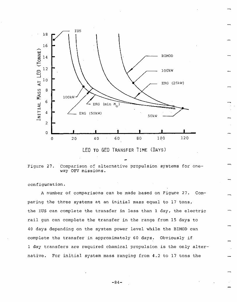
120
ERG (25kW)
BIMOD
lOOkW
100
50kW
806040
ERG (50kW)
IUS
20
18
16,......IJ.J
~ 140I-.......0
12w-...J
l- 10«(j) 8(j)
«:E
--I 6«......I- 4z......
2
00
LEO TO GEO TRANSFER TIME (DAYS)
Figure 27. Comparison of alternative propulsion systems for oneway OTV missions.
configuration.
A number of comparisons can be made based on Figure 27. Com-
paring the three systems at an initial mass equal to 17 tons,
the IUS can complete the transfer in less than 1 day, the electric
rail gun can complete the transfer in the range from 15 days to
40 days depending on the system power level while the BIMOD can
complete the transfer in approximately 60 days. Obviously if
1 day transfers are required chemical propulsion is the only alter-
native. For initial system mass ranging from 4.2 to 17 tons the
-84-
electric rail gun system can complete the transfer in the range
from 15 to 130 days depending on the power level. The BIMOD in
this mass range always has a longer trip time than the rail gun
and ranges from 60 days to 130 days. For initial mass less than
4.2 tons both electric propulsion systems have trip times longer
than 130 days but the higher specific impulse of the BIMOD makes
it more attractive (i.e., lower mass).
The two electric propulsion alternatives may also be compared
by imposing constraints on the system power level. Limiting the
power to 100 kWe the electric rail gun system could accomplish
the transfer in times as short as 15 days, albeit with a severe
mass penalty. If we constrain the power to '100 kvl and theelece
tric rail gun system mass is about equal to BIMOD system mass.
The rail gun system can complete the transfer in 25 days while
the BIMOD could accomplish the transfer in approximately 75 days.
If the power level is constrained to 50 kWe , the electric rail
gun could complete the mission in as short as 22 days. If the'
mass is constrained to the same mass as the BIMOD at 50 kW thee
rail gun could complete transfer in 110 days while the BIMOD could
complete the transfer in 120 days. At 25 kW the electric raile
gun can complete the transfer in as short as 40 days. However
at trip times longer than about 110 days the superior specific
impulse of the BIMOD makes it more attractive.
In general comparing the two electric propulsion systems,
for transfer times less than 130 days the electric rail gun system
is more attractive than the BIMOD while at trip times greater
than 130 days the BIMOD is more attractive than the electric rail
gun.
-85-

-86-
SECTION 4
CONCLUSIONS AND RECOMMENDATIONS
A system concept has been developed for an electric rail
gun based propulsion system for space applications. The sub
systems and components associated with the major power flow on
an electric rail gun system have been identified and the perform
ance analysed. State-of-the-art or near term advancements in
component technology have been assumed in the subsystem and sys
tem evaluation. In this section, we describe our conclusions
about the electric rail gun propulsion concept. We also describe
our assessment of the technology development requirements and
make recommendations for further development of the electric rail
gun propulsion concept.
We conclude that an electric rail gun propulsion system is
technically feasible. We found no problems which in principle
would block technical accomplishment. In fact, most of the required
technology is largely developed. We also conclude that an electric
rail gun propulsion OTV system would be most attractive for missions
requiring orbital transfers in less than 120 days. In the 20
to 120 day mission transfer regime the electric rail gun system
would have both lower initial deployed mass and lower propellant
requirement than a BIMOD ion thruster system and the IUS chemical
propulsion system. At transfer times less than 20 days the IUS
system is the only alternative and at transfer times greater than
120 days the superior efficiency and specific impulse of the BIMOD
make it more attractive (i.e., lower mass). Finally, the electric
-87-

rail gun OTV system becomes increasingly attractive as payload
mass increases. Both the ratio of propellant mass-to-payload
mass and initial system mass-to-payload mass decrease with increas
ing payload mass. The attractive performance characteristics
of an electric rail gun system will require, however, substantial
investment in system development.
In the course of our subsystem investigations we assessed
the state of current technology compared to the technology require
ments of the electric rail gun propulsion system. We conclude
that each subsystem requires important developmental work.
The SEPS type solar cell array would be compatible with an
electric rail gun OTV. The domination of electric propulsion
system mass by the power supply, however, places a premium on
low specific mass power supplies. Successful development of such
supplies would improve the attractiveness of all electric propulsion
systems. In addition, the severe radiation degradation of current
silicon solar cells implies that alternative technologies must
be developed for LEO to GEO missions. Efforts to develop advanced
spaceborne power supplies which overcome these problems (GaAIAs
solar cell arrays; and nuclear electric power supplies) are already
under way as part of other technology development programs.
Power conditioning components suitable for the electric rail
gun system are also being developed in conjunction with other
spaceborne and airborne systems. Advanced resonant DC converters,
capacitors, inductors, and switches are currently under development.
Improvements in specific mass of these components are desirable,
but compatability to electric rail gun circuits is required. Life
-88-

and reliability of DC converters, capacitors and switches must
also be demonstrated.
The electric rail gun is obviously the key to the rail gun
propulsion concept and it is the least developed component. Two
major development milestones are required. First, rail gun pellet
exhaust velocity must be demonstrated in the range from 5 km/s
to 20 km/s. The second major milestone is demonstration of long
life, high reliability operation at these high exhaust velocities.
Successful solutions to barrel erosion, thermal fatigue and mechan
ical fatigue will require substantial developmental work. In
addition, rail gun efficiency and performance scaling must be
proven experimentally in the ranges of interest for electric rail
gun propulsion.
Waste heat radiator technology is relatively well developed.
The major development areas specific to electric rail gun propul
sion include demonstration of long life radiators which are compat
able to electric rail guns. Low mass, low power heat removal
at high thermal power density from the rails must also be demon
strated.
Several options appear to be· available for propellant handling
and pellet loading. The major developmental requirement is demon
stration of reliable, long life operation of the mechanical com
ponents.
Safe pellet disposal after launch is of critical importance
to technical acceptability of an electric rail gun OTV system
(or any other pellet launching concept). Pellet orbital control
or pellet material selection (for sublimation) appear to be
-89-

feasible approaches to this problem. However for near earth space
further analyses are required to investigate the pellet hazard
to other spacecraft· during the pellet disposal process.
An important step in any advanced electric propulsion con
cept development is the establishment of mission requirements
for the propulsion device. In particular, the importance of or
bital transfer time must be quantified and the benefits identified.
The development of the rail gun propulsion system should
take a number of specific steps.
We feel that a development program should first address the
development of the electric rail gun. The acceleration of pellets
in the size range and to the velocities required for propulsion
system operation must be demonstrated. Launcher life and reliabil
ity demonstrations would be the second major developmental goal.
Power conditioning, pellet loading and waste heat removal specific
to repetitive rail gun operation could be performed in parallel,
after basic rail gun velocity and performance capabilit~es are
proven.
Pellet disposal problems should receive further detailed
treatment early in propulsion system development. Spacecraft
safety hazards and/or political constraints must be satisfied
early for overall concept acceptance.
-90-
-

LIST OF REFERENCES
1. Bauer, D., Barber, J., Swift, H., and Vahlberg, C., "ElectricRail Gun Propulsion Study (Advanced Electric Propulsion Technology High Thrust)", Air Force Rocket Propulsion Laboratory,AFRPL-TR-81-02, December 1980.
2. Rashleigh, S., and Marshall., R., "Electromagnetic Accelerationof Macroparticles to High Velocities," J. Appl. Phys., March1978.
3. Hawke, R., et aI, "Results of Railgun Experiments Powered byMagnetic Flux Compression Generators," Lawrence Liverm.oreNational Laboratory, UCRL-84875, 1980.
4. Barber, J., "The Acceleration of Macroparticles in a Hypervelocity Electromagnetic Accelerator," Ph.D. Thesis, TheAustralian National University, 1972.
5. Young, L., "Solar Array Technology for Solar Electric Propulsion Missions," AIAA Paper No. 79-3086, Presented at the 14thInternational Electric Propulsion Conference, Princeton, NJ,October 30 - November 1, 1979.
6. Tada, H., and Carter, J. Jr., "Solar Cell Radiation Handbook,"JPL Publication 77-56, Jet Propulsion Laboratory, Pasadena, CA,November 1977.
7. Hanley, G.M., "Evolution of Satellite Power System (SPS)Concepts," Report No. 78-9403, In Proceedings of the 13thIntersociety Energy Conversion Conference, August 20-25,1978, San Diego, CA.
8. Tonelli, A.D., and Nussberger, A.A., "The Design and Evaluation of a 5 GW Ga-AI-As Solar Power Satellite (SPS) ," ReportNo. 78-9404, In Proceedings of the 13th Intersociety EnergyConversion Conference, August 20-25, 19.78, San Diego, CA.
9. Harris, C., and Crede, C., Ed., "Shock and Vibration Handbook,"McGraw Hill Book Company, 1976, Chapters 36 and 37.
10. Biess, J., Inouie, J., and Schoenfeld, A., "Thyristor PowerProcessor for the 30 cm Mercury Electric Propulsion Engine,"AlAA Paper 75-433, 1975.
11. Hansen, I., "Description of a 2.2 kW Power Transformer forSpace Application," NASA Technical Memorandum 79138, NASALewis Research Center, 1979.
12. Schwarz, F., "A 10 kW Lightweight DC Converter (TechnologyFeasibility Study for Lightweight Megawatt Range Converters),"AFAPL-TR-77-45, Air Force Aero Propulsion Laboratory, WrightPatterson AFB, 1977.
-91-

13. Byers, D., Terdan, F., and Meyers, I., "Primary ElectricPropulsion for Future Space Missions," NASA Technical Memorandum 79141, NASA-Lewis Research Center, Cleveland, Ohio,1979.
14. Ramrus, A., "Development of a High Energy Density Capacitorfor Plasma Thrusters," Air Force Rocket Propulsion Laboratory,Report No. AFRPL~TR-80-35, October 1980.
15. Westinghouse, Inc., Data Sheet for Fast Switching Thyristor,SCR-T9GH.
16. Westinghouse, Inc., General Purpose Rectifiers Data Sheet,R920.
17. Grover, F.W., Inductance Calculations--Working Formulas andTables, D. Van Nostrand Company, Inc., Copyright 1946.
18. NASA-Lewis Research Center, "30-cm Ion Thrust Subsystem DesignManual," NASA Technical Memorandum 79191, Jurie 1979.
19. Leach, J., and Stalmach, D., "Optimum Design of SpacecraftRadiators for Large Capacity or Long Duration Mission Applications," Paper No. 79-ENAs-IO, American Society of MechanicalEngineers, 1979.
20. Nelson, W., and Howell, H., "Orbital Service Module ThermalControl System Design," Paper No. 79-ENAs-22, American Societyof Mechanical Engineers, 1979.
21. Filippi, F., Nervegna, N., and Zarotti, G., "Modularity andOptimization in Fluid Loop Radiator Systems," Paper No. 79-ENAs-37,American Society of Mechanical Engin~ers, 1979.
22. Weidner, D., "Space Environment Criteria Guidelines for Usein Space Vehicle Development (1969) (Revision) ," NASA-TMX-53957, 1969.
23. Wright, J., "Optimization of Large Heat Pipe Radiators for LongLift Space Heat Rej ection Systems," 'Paper No. 79-ENAs-25, American Society of Mechanical Engineers, 1979.
24. American Metal Climax, Inc., "AHZIRC," AMAX Publication No.OF/66-2791, 1966.
25. Alario, J. and Haslett, R., "Modular Heat Pipe Radiators forEnhanced Shuttle Mission Capabilities," Paper No. 79-ENAs-17,American Society of Mechancial Engineers, 1979.
26. Ellis, W., "Radiator Heat Rejection Options for Shuttle Payloads," Paper No. 79-ENAs-18, American Society of MechanicalEngineers, 1979.
-92-

27. Koenig, D., Ranken, W., and Salmi, E., "Heat Pipe Reactorsfor Space Power Applications," AIAA Paper No. 77-491, AmericanInstitute of Aeronautics and Astronautics, 1977.
28. Kreith, F., Principals of Heat Transfer,Intext EducationalPublishers, New York, 1973, pg 14.
29. NASA, "NASA Space Systems Technology Model," To Be published.
-93-

APPENDIX A
ELECTRIC GUN MISSION ANALYSIS
RESULTS FOR NASA
C. JULIAN VAHLBERG
BUSINESS AND TECHNOLOGICAL SYSTEMS, INC.
A-I

A-2
BC,81:VESS IN/) TECHNOLO(;JCn SYSTEMS, INC.
TABLE OF CONTENTS
1•a INTRODUCTION ..•.....•.•...........•.......................... A - 5
2.0 ENGINE MODELING AND MASS DIFFERENTIAL EqUATIONS A-7
3.0 ORBITAL OPTIMIZATION EqUATIONS ...................•........... A-II
3.1 Basic Orbital Transfer Equations A-II
3.2 Optimal Exhaust Velocity Results A-13
3.4 Constra int Upon Exhaust Velocity A-14
4.0 INITIAL AND PROPELLANT MASS FOR SPECIFIC MISSIONS A-17
4.1 Missions Being Considered A-17
4.2 Analytic' Results for t~e Missions ..•......•...•.•....... A-20
5.0 MISSION. ANALYSIS RESULTS .............•........................ A-23
5.1 Electric Rail Gun Performance Evaluation ..............•. A-23
5.2 Comparison with BIMOD ' A-33
5.3 Comparison with Inertial Upper Stage (IUS) A-40
6.0 CONCLUSIONS AND RECOMMENDATIONS A-45
7.0 REFERENCES ; . . . . . . .. A- 47
APPENDIX AA w A-49
APPENDIX AB ' A-53
APPENDIX AC ...........•.. II •••••••••••••••••••••••••••••••••••••••• A-55
A-3

A-4
BlJSINESS AND TECHNOLOGICAL SYSTEMS, INC.
1.0 INTRODUCTION
The electric rail gun (Reference 1) has been recognized as a potentially important space propulsion system. Pellet exhaust velocitieshave already been demonstrated which are higher than current chemicalrocket exhaust velocities. Even higher exhaust velocities are probablyachievable. Thus, the specific impulse is higher, hence propellant consumption lower than for chemical rockets. However, power must be provided by solar cell or nuclear power systems.
Ion thrusters such as BIMOD (Reference 2), which also requireseparate power systems, have an even higher specific impulse than probablyachieveable using a rail gun. However, they are much heavier relative tothe thrust developed than the rail gun. Thus, past mission analyses usingion thrusters are not applicable due to the differences in propulsionsystem mass.
The rail gun has a significant advantage over ion propulsion systemssince it can provide very high thrust levels, albeit at a low'acceleration (relative to gravity) due to the relatively small mass of the powersupply. These high thrust levels offer NASA an alternative to ionthrusters which require longer transfer times and chemical rockets whichrequire large propellant masses.
This report provides documentation on studies investigating theimplication upon mission planning of the rail gun concept. It is acontinuation of the effort documented in Reference 3 which was based uponAir Force desires to raise 5,12.5 and 2'5 ton payloads from 1m·, earthorbit (LEO) to geosynchronous orbit (GEO), then return the propulsionsystem to LEO. This effort has focused upon the smaller payloads whichare of interest to NASA (1150 kg and 2300 kg).
The effort has been divided into analytic studies to size the systemand determine basic tradeoffs, followed by numerical studies to determine
A-5
BLS/:\ESS A.YD TEClL\'OLOG/C..tL SYSTEJ1S, INC.
the effects of some of the more important effects of space flight inearth orbit. The report is organized as follows. Chapter 2 presents
. the analytical mass differential equations applicable to any propulsionsystem. Chapter 3 presents the optimal orbital differential equationsapplicable to transfers for which the pr~pulsion acceleration is smallerthan the gravitational acceleration. Some specific expressions forinitial and propellant mass are presented in Chapter 4 which are applicable to this mission for which the power plant must be returned toLEO. Results of numerically minimizing those expressions are presentedin Chapter 5 along with a comparison with the currently available BIMOOand Inertial Upper Stage (IUS). Conclusions and recommendations forfurther studies are presented in Chapter 6.
The effects of solar shadowing, as determined using the SECKSPOTComputer program, are given in Appendix A. Appendix B presents the formuf equations used for the propulsion system mass and efficiency. AppendixC contains a glossary of symbols used in this report.
A-6
BUSINESS AND TECHNOLOGICAL SYSTEMS, INC.
2.0 ENGINE MODELING MID MASS DI FFERENTIAL EQUATIONS
This chapter presents the models and equations for propellant massdepletion used for this qnalysis. They are derived from the fundamentalphysics which represent rail gun performance. Similar expressions werederived in Reference 4. From the conservation of momentum we have:
where
m IAI = - mc
m= total spacecraft mass
A= spacecraft acceleration
.m= rate of depleting fuel ~ a
c = fuel exhaust velocity ~ a .
(2-1)
However, since the power is provided by a solar or nuclear power supplythe power is limited. We, therefore, have the constraint:
P l. 2n =- mc2
where
P = total power provided by power supply
n ='propulsion system efficiency.
In general, it is assumed that all available power is being used.Combining equations (2-1) and (2-2) yields:
A-7
(2-2)
(2-3)
BLSI.YESSL\'0 TECJI:'V()U)(;[(.AL 5 rSTEJIS. INC.
Alternatively:
• = 2nPm -7 (2-4)
as the expression for the fuel depletion as a function of either space
craft, acceleration, A, or the exhaust velocity, c. Either one equation or the ot~er will be used in other analyses depending· upon whatassumptions are made on the acceleration or exhaust velocity.
The relationship between acceleration and exhaust velocity is given
by equation (2-5):
A = 2nPme
A general solution to equation (2-3) is given by:
where
L2(t)= 1. tJ~ ds2 nTST
a
(2-5)
(2-6)
(2-7)
In the speci a1 case of constant accelerati on, A , and engirre effi ci ency, n
L2(t) :: L2 ~ (2-8)1 t f
where
. 2 2~u (2-9)Ll = 2nt f
A-8
BUSINESS AND TECHNOLOGICAL SYSTEMS, INC.
~u = equivalent change in linearvelocity caused by A
t f
=f IAI dto
t f = total transfer time.
The propellant used to accomplish this change in velocity is given by:
(2-10)
The power and hence the power plant mass have not been specified yet.However, they will have a very critical effect upon the propellant usedor equivalently, the initial mass, mo ' since it would be a criticalcomponent of m . In addition, obviously, the final mass must always beogreater than the sum of the payload and propulsion system masses. The meansfor determining the optimal P will be given in a later section.
For the special case of constant exhaust velocity, c, the solutionto equation (2-4) is given by:
m(t) (2-11)
Alternatively, equation (2-1) can be rewritten as:
.~ c = - IAIm
and integrated in combination with:
.IAIu =
A-9
(2-12)
(2-13)
BL SnE.'i.'i -t\1) TEf.H.\OLO(;If.AL S rSTE.lfS. he.
to yield:
m(t) :i: mo (2-14)
(2-15)
The propellant used is, thus, giv~n by:
(2-16)
For this case, there are three (assumed) constant parameters: P, c, t f .The choice (specification) of any two of these implies a value for thethird. Alternatively, if less than two are specified then the excess parameters can be optimally chosen to minimize some other parameter ofinterest.
A-IO
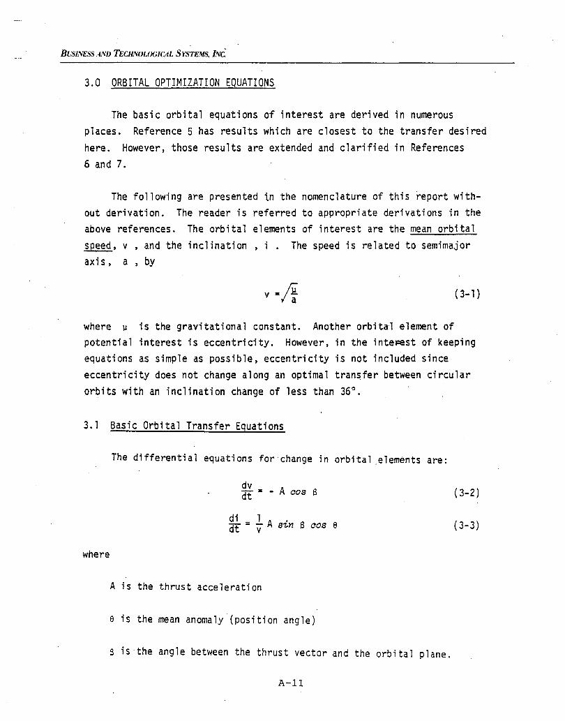
BUSINESS AND TECHNOLOGICAL SYSTEMS, INC.'
3.0 ORBITAL OPTIMIZATION EQUATIONS
The basic orbital equations of interest are derived in numerousplaces. Reference 5 has results which are closest to the transfer desiredhere. However, those results are extended and clarified in References
6 and 7.
The following are presented in the nomenclature of this report without derivation. The reader is referred to appropriate derivations in theabove references. The orbital elements of interest are the mean orbitalspeed, v , and the inclination, i . The speed is related to semimajoraxi S , a, by
v =~ (3-1)
where 1.1 is the gravitational constant. Another orbital element ofpotential interest is eccentricity. However, in the inteFest of keepingequations as simple as possible, eccentricity is not included sinceeccentricity does not change along an optimal transfer between circularorbits with an inclination change of less than 36°.
3.1 Basic Orbital Transfer Equations
The differential equations for change in orbital ,elements are:
where
dvdt = - A cos a
di 1 A .dt = V S1,n a cos e
(3-2)
(3-3 )
A is the thrust acceleration
e is the mean anomaly '(position angle)
a is the angle between the thrust vector and the orbital plane.
A-II
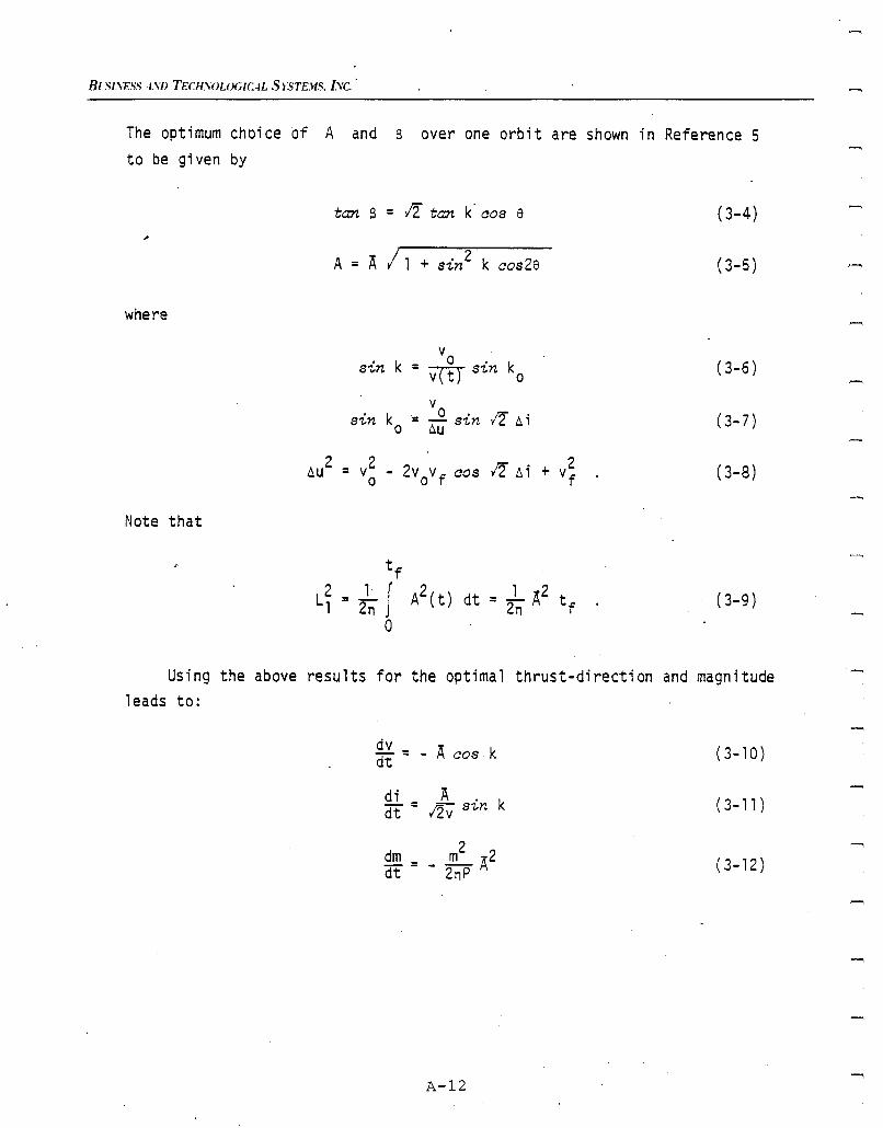
Be Sl.\ES.'i -tso TECHSOLOG1C-tL S rSTE.US. I.vc. .
The optimum choice of A and 6 over one orbit are shown in Reference 5to be given by
where
Note that
tan 6 = 1:2 tan k' cos e
A = A / 1 + sin2 k cos2e
sin kVo .
k=vrtT s-z..n 0
vsin ko
. 0 • 12 Do i= - s-z..ntlu
DoU2 = v2 - 2vovf cos 1:2 D. i + v2
0 f
(3-4)
(3-5)
(3-6)
(3-7)
(3-8)
dt = _1 "{..2 tf
.2n (3-9)
Using the above results for the optimal thrust-direction and magnitudeleads to:
dv = _"A cos k (3-10)dt
.9.i.= Ak (3-11 )dt I2v sin
dm _ 2m -2 (3-12)dt - - -A2nP
A-12
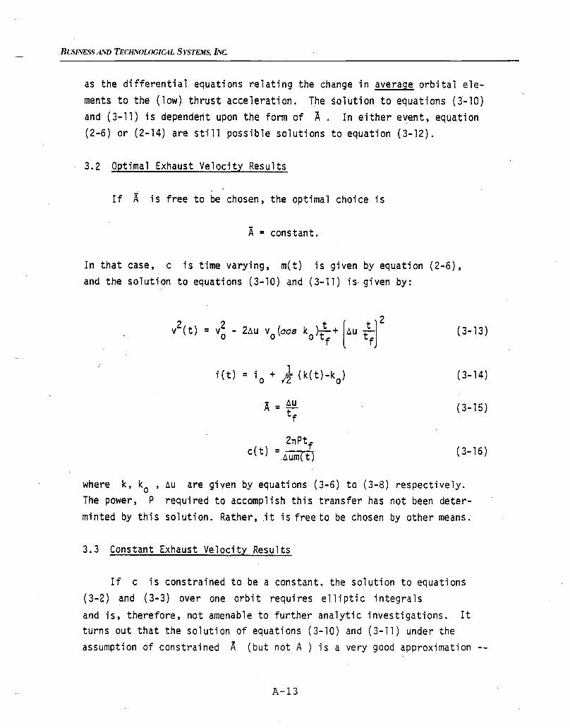
BUSINESS AND TECHNOLOGICAL SYSTEMS, INC.
as the differential equations relating the change in average orbital elements to the (low) thrust acceleration. The solution to equations (3-10)and (3-11) is dependent upon the form of A. In either e~ent, equation(2-6) or (2-14) are still possible solutions to equation (3-12).
3.2 Optimal Exhaust Velocity Results
If A is free to be chosen, the optimal choice is
A = constant.
In that case, c is time varying, m(t) is given by equation (2-6),and the solution to equations (3-10) and (3-11) is· given by:
(3-13 )
(3-14)
(3-15)
(3-16)
where k, ko ,~u are given by equations (3-6) to (3-8) respectively.The power, P required to accomplish this transfer has not been determi nted by thi.s sol uti on. Rat.her, .it is free to be chosen by other means.
3.3 Constant Exhaust Velocity Results
If c is constrained to be a constant. the solution to equations(3-2) and (3-3) over one orbit requires elliptic integralsand is, therefore, not amenable to further analytic investigations. Itturns out that the solution of equations (3-10) and (3-11) under theassumption of constrained A (but not A ) is a very good approximation
A-l3
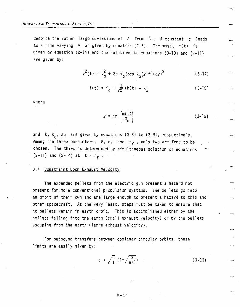
BUil\E."i.'; .t.\/) TECH.\OLOG/CAL SrSTEJfS, I.Vc.
despite the rather large deviations of A from A. A constant c leadsto a time varying A as given by equation (2-5). The mass, m(t) isgiven by equation (2-14) and the solutions to equations (3-10) and (3-11)are given by:
(3-17)
(3-18)
where
(3-19)
and k, ko' ~u are given by equations (3-6) to (3-8), respectively.Among the three parameters, P, c, and t f , only two are· free to bechosen. The third is determined by simultaneou·s solution of equations(2- 11) and (2 - 14) at t = t f .
3.4 Constraint Upon Exhaust Velocity
The expended pellets from the electric gun present a hazard notpresent for more conventional propulsion systems. The pellets go intoan orbit of thei r own and are 1arge enough to present a hazard to thi s. andother spacecraft. At the very least, steps must be taken to ensure thatno pellets remain in earth orbit. This is accomplished either by thepellets falling into the earth (small exhaust velocity) or by the pelletsescaping from the earth (large exhaust velocity).
For outbound transfers between coplanar circular orbits, theselimits are easily given QY:
(3-20)
A-14
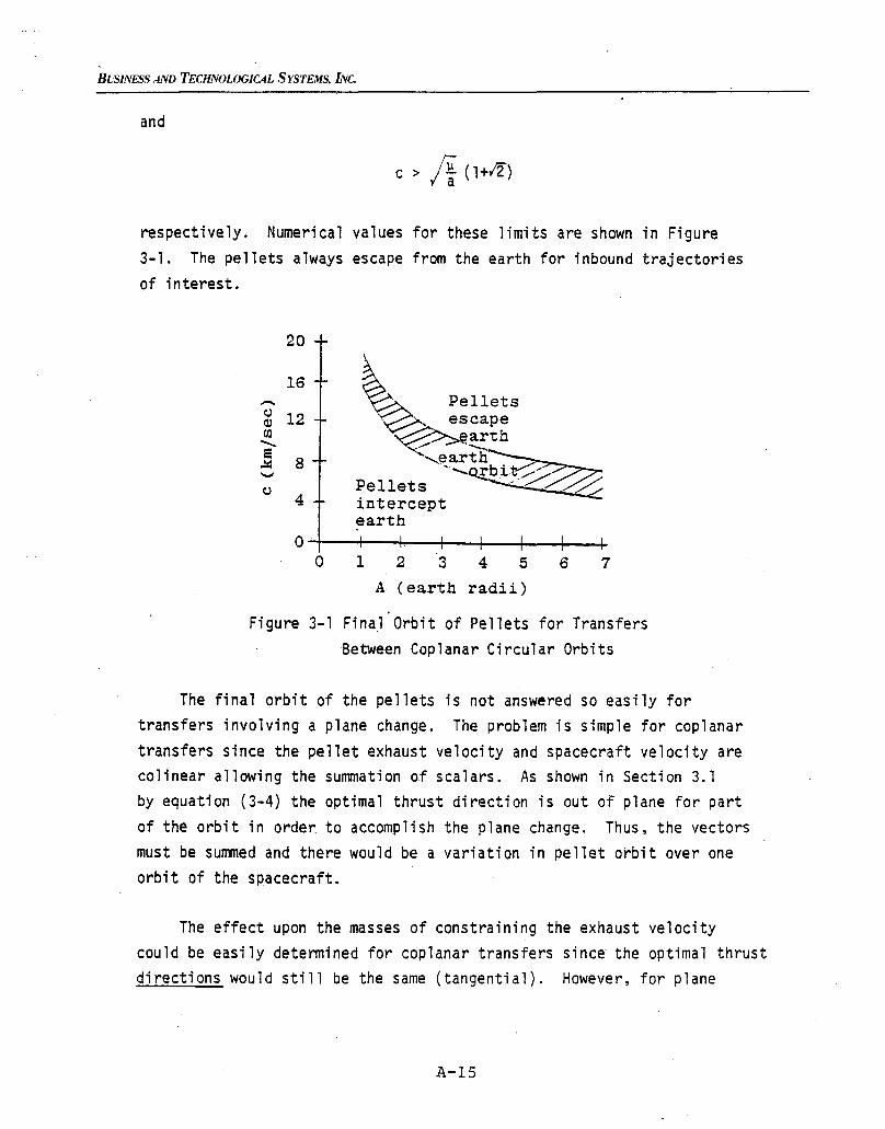
BUSINESS AND TECHNOWGICAL SYSTEMS, INC.
and
c > A(1+12)
respectively. Numerical values for these limits are shown in Figure3-1. The pellets always escape from the earth for inbound trajectoriesof interest.
20
16-~ 12(JJ
........
~ 8....,
4
~ Pellets~, escape~arth
'<,eart~'· ........O.!:bit ...../Pe11et s .. :::----: :/::::interceptearth
OT--t--r.---+--+---+--~--4-
o 1 2 3 4 5 6 7
A (earth radii)
Figure 3-1 Fina.l Orbit of Pellets for TransfersBetween Coplanar Circular Orbits
The final orbit of the pellets is not answered so easily fortransfers involving a plane change. The problem is simple for coplanartransfers since the pellet exhaust velocity and spacecraft velocity arecolinear allowing the summation of scalars. As shown in Section 3.1by equation (3-4) the optimal thrust direction is out of plane for partof the orbit in order to accomplish the plane change. Thus, the vectorsmust be summed and there would be a variation in pellet orbit over oneorbit of the spacecraft.
The effect upon the masses of constraining the exhaust velocitycould be easily determined for coplanar transfers since· the optimal thrustdirections would still be the same (tangential). However, for plane
A-IS

BlSI.\ESS-J..\'D TECHYOLO(;lr.AL S rSTEJfS. Lye,
chan9~s, the constraint on exhaust velocity certainly would change thethrust directions. It is possible that the penalty in prope"'ant masswould be quite small. Further investigations are, unfortunately, beyondthe scope of this effort.
A-16
BUSINESS AND TECHNOLOGICAL SYSTEMS, INc.
4.0 INITIAL AND PROPELLANT MASS FOR SPECIFIC MISSIONS
This chapter ~resents the missions being considered along withanalytic equations for initial mass and propellant mass under variousassumptions about pellet exhaust velocity. The equations presentedcan be minimized by choice of P or c. Results of numerical minimization of these equations are presented in Chapter 5..
4.1 Missions Being Considered
The electric gun is being considered as the propulsion system toaccomplish the following mission:
• Go from low earth orbit (LEO) to geosynchronous orbit (GEO)in the specified time t f1
Leave· the payload, m ,there7T .
Return to LEO in the minimum time possible given the availablepropulsion system
• The final mass in LEO will be the reusable power plant andpropulsion system.
A second mission being considered consists simply of the LEO to GEOtransfer in the specified time t f . The parameters describing these. 1or~ita1 transfers are given in Table 4-1. The basis for the equivalent6u , taking shadowing and other non-ideal effects into account, is presented in Appendix A.The propulsion system mass, m ,as derived ineAppendix B from the data in Reference 9, is a function of the output
power, P
me = 17800 P + 25
A-17
(4-1 )
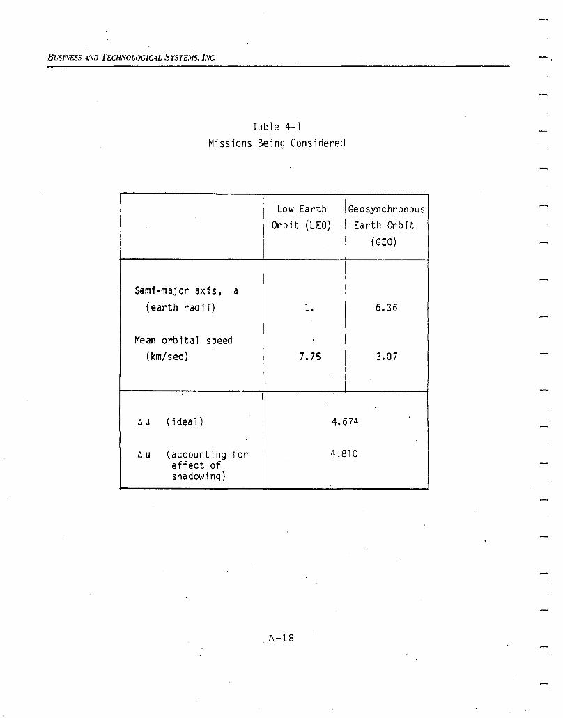
BLSliVESS AND TEClL'VOLOGICAL SYSTE.lIS, L'Vc.
Table 4-1
Missions Being Considered
Low Earth
Orbit (LEO)
Semi-major axis, a
(earth radii)
Geosynchronous
Earth Orbit
(GEO)
6.36
Mean orbital speed
(km/sec)
6 u (i dea1)
6 u (account; ng foreffect ofshadowing)
A-IS
7.75
4.674
4.810
3.07
.....,
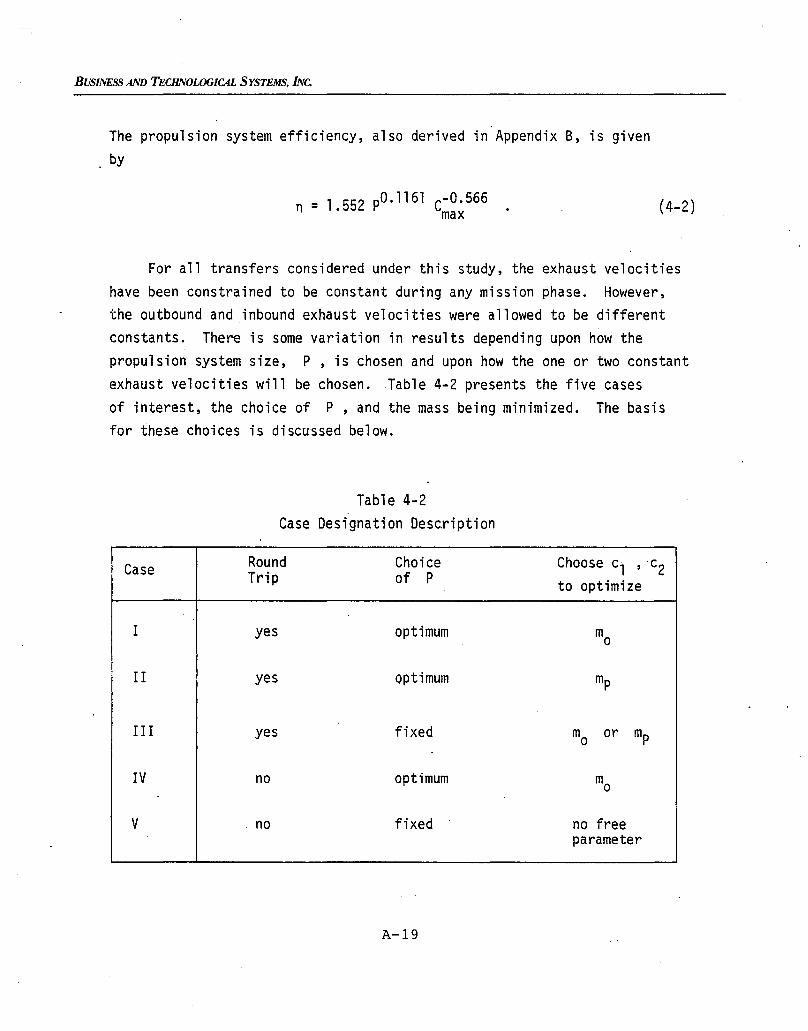
BUSINESS AND TECHNOLOGICAL SYSTEMS, INc.
The propulsion system efficiency, also derived in Appendix B, is givenby
n =1.552 pO.1161 C-O. 566max (4-2)
For all transfers considered under this study, the exhaust velocitieshave been constrained to be constant during any mission phase. However,the outbound and inbound exhaust velocities were allowed to be differentconstants. There is some variation in results depending upon how thepropulsion system size, p, is chosen and upon how the one or two constantexhaust velocities will be chosen. Table 4-2 presents the five casesof interest, the choice of P, and the mass being minimized. The basisfor these choices is discussed below.
Table 4-2Case Designation Description
Case Round Choice Choose cl , c2Trip of P to optimize
I yes optimum mo
II yes optimum mp
III yes fixed mo or mp
IV no optimum mo
V no fixed no freeparameter
A-19
BLSI.'ESS AND TECHNOLOGICAL SYSTEMS, INC.
An electric propulsion system has the advantage of lower propellantmass than chemical rockets, yet there is a penalty for the large propulsionsystem mass. Thus the first three cases assume that the propulsionsystem is returned to LEO for reuse. For comparison, the last two casesassume an outbound transfer only to determine whether more propellantis required to return the power plant than the mass of the power plantitself.
Clearly, it is possible to reduce the mass requirements if moresystem parameters are free to be chosen. Thus Cases I, II, and IV seekthe optimum propulsion system size and exhaust velocities in order tominimize some choice of mass. The minimization of initial mass (CasesI and IV) reflects the cost of putting the total system in LEO. Onth~ other hand, minimization of propellant mass (Case II) reflects onlythe cost of the new fuel required to reuse a spacecraft. For outboundonly transfers (Cases IV and V) there is no relevance to minimizingpropellant alone, since the system is not returned for reuse.
The optimum choice of propulsion system size and exhaust velocitiesmay not be practical since it is possible that only certain standardsystems will be available. However, the optimum results yield interestinginsight into how much mass reduction is possible by a different choiceof parameters. For comparison, two cases (III and V) considered a fixedpropulsion system size. Since P is fixed for Case III, there is nodifference between minimizing mo and mp , the result is the same.For Case V, with P fixed there is no free parameter. The outboundexhaust velocity must be chosen so that the transfer is accomplishedin the specified time.
4.2 Analytic Results for the Missions
The mass time history for both the outbound and inbound legs ofthe transfer is given by Equation (2-14). The initial mass for theinbound leg is the final mass from the outbound leg minus the payload.The final mass from the inbound leg is the power plant mass. In order
A-20
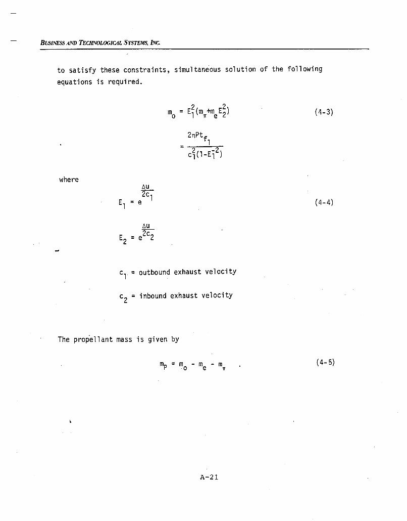
BUSINESS AND TECHNOLOGICAL SYSTEMS, INc.
to satisfy these constraints, simultaneous solution of the following
equations is required.
= 2 -2cl(l-El )
where
t.u
E =e2c22
Cl = outbound exhaust velocity
c2
= inbound exhaust velocity
The propellant mass is given by
A-21
(4-3)
(4-4)
(4- 5)
BLSINESS AND TECHNOLOGICAL SYSTEMS. INC.
Simultaneous solution of Equations· 4-3 and 4-4 must be obtained numerically. The results of those numerical studies are presented in Chapter5. If P is free to be chosen, it can be varied to satisfy the equations.Then, cl and c2 can be varied to minimize either Equation 4-3 (Case .I) or ~quation 4-5 (Case II). If P is fixed, as in Case III, Equations4-3 and 4-4 must be satisfied by choice of cl leaving only c2 freeto minimize mo or equivalently mp (since me is fixed).
Since the exhaust velocity for the return leg is determined byone of the above criteria, the return time of flight is not free tobe chosen. It is gi ven by
(4-6)
Note that the return time is independent of~outbound time .if the propulsionsystem mass, me' is linearly proportional to power output and if theefficiency is the same for the different transfers. Some reductionin mass is possible for larger times'of flight if the thrust is notprovided continuously. Those small improvements have not been calculatedsince timeliness of the return was considered to be more important.
For outbound-only transfers (Cases IV and V), Equations 4-3 and4-4 can be used by setting E2 = 1 and eliminating c2 as a parameter.Case IV seeks the minimum initial mass by choice of cl with P constrained by the simultaneous solution of Equations 4-3 and 4-4. Whenp is chosen to be some fixed value (Case V), then cl must be chosento satisfy the two equations and there are no free parameters for anoptimization.
A-22
BUSINESS AND TECHNOLOGICAL SYSTEMS, INc.
5.0 MISSION ANALYSIS RESULTS
The results of numerically minimizing the mass expressions presentedin Chapter 4.0 are presented in this chapter. An evaluation of electricrail gun performance for the five cases of interest are presented inSection 5.1. Electric gun performance is compared with BIMOD in Section5.2 and the Inertial Upper Stage (IUS) in Section 5.3.
Based upon the results of an earlier study (Reference 3), the higher valuesof ~u (presented in Table 4-1) representing the effect of solar shadow-ing were used in this solution of the analytic equations. Thus, theresults in this chapter represent the masses and power plant sizes whichwould be required considering the effect of solar shadowing. The timesof flight, however, are the ideal times. Shadowing lengthens the transfersby about 25 percent.
5.1 Electric Rail Gun Performance Evaluation
The power plant size in kilowatts, initial and propellant massesin kg, and relevant exhaust velocities in km/sec are given in Tables5-1 and 5-2 for missions to raise 2300 kg and 1150 kg payloads, respectively. The results are plotted in Figures 5-1 through 5-9 for the2300 kg case. Similar shaped curves were obtained for the smaller payload.Some observations on these curves (and companion numbers in Table5-1) are appropriate.
As shown in Figures 5-1 and 5-2, minimizing mo (Case I) resultsin a slightly lower initial mass than if mp is minimized (Case II).The converse is also true. Yet, as shown in Figure 5-3, there is alarge difference in the required propulsion system size, P. Thisdemonstrates the extent to which the minimum is relatively flat andcomparable results can be obtained over a range of parameters.
The optimum choice of P is for Cases I and II is larger thanthe specified range (10 to 50 KW). The Case II results for P = 50
A-23
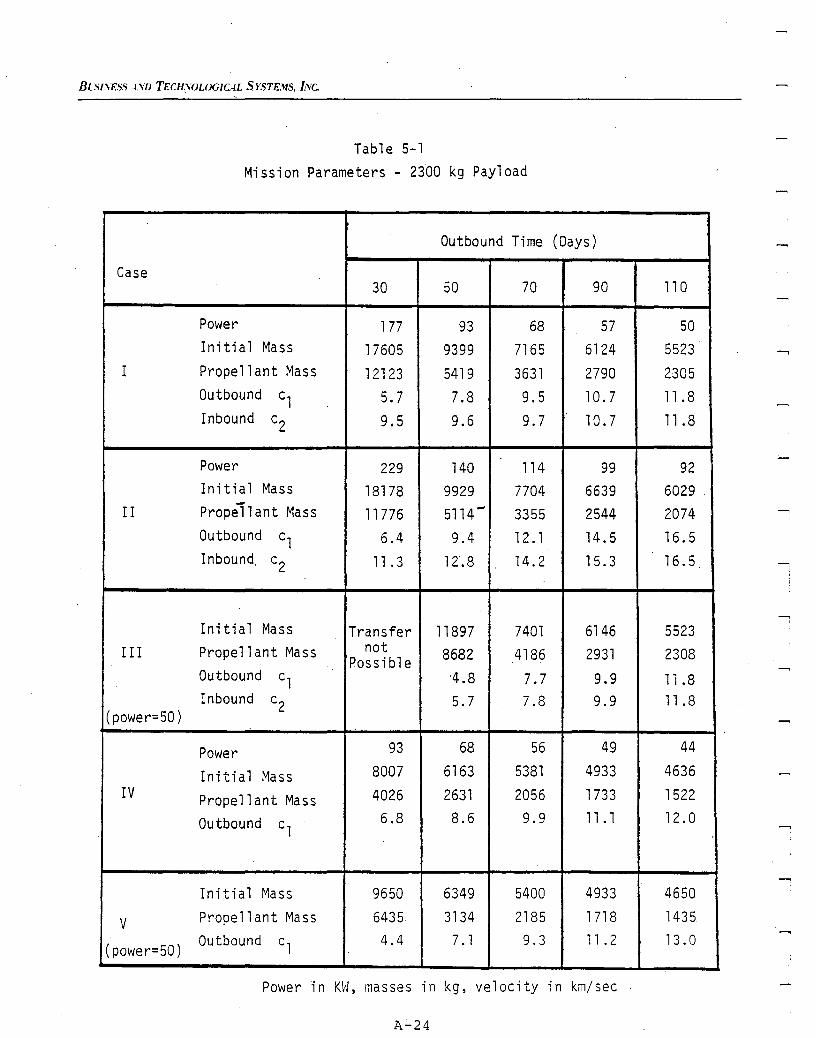
BC.Sl.'ESS-tVD TECH{WJLOGICAL SYSTEMS, I'Ve.
Table 5-1Mission Parameters - 2300 kg Payload
Outbound Time (Days)
Case30 50 70 90 110
Power 177 93 68 57 50Initi a1 Mass 17605 9399 7165 6124 5523
I Prope 11 ant Mass 12123 5419 3631 2790 2305Outbound c1 5.7 7.8 9.5 10.7 11.8Inbound c2 9.5 9.6 9.7 10.7 11 .8
Power 229 140 114 99 92Initial Mass 18178 9929 7704 6639 6029-II Prope11 ant Mass 11776 5114 - 3355 2544 2074Outbound c1 6.4 9.4 12. 1 14.5 16.5Inbound. c2 11.3 12.8 14.2 15.3 16.5
Init i alMa ss Transfer 11897 7401 6146 5523III Propellant Mass not 8682 4186 2931 2308Possible
Outbound c1 A.8 7.7 9.9 li .8Inbound c2 5.7 7.8 9.9 11 .8
(power=50)
Power 93 68 56 49 44
Initi a1 Mass 8007 6163 5381 4933 4636IV Propellant Mass 4026 2631 2056 1733 1522
Outbound c16.8 8.6 9.9 11 .1 12.0
In i t i a1 ~~a ss 9650 6349 5400 4933 4650
V Prope 11 ant Mass 6435 3134 2185 1718 1435
(power=50)Outbound c1 4.4 7. 1 9.3 11 .2 13.0
Power in KW, masses in kg, velocity in km/sec .
A-24
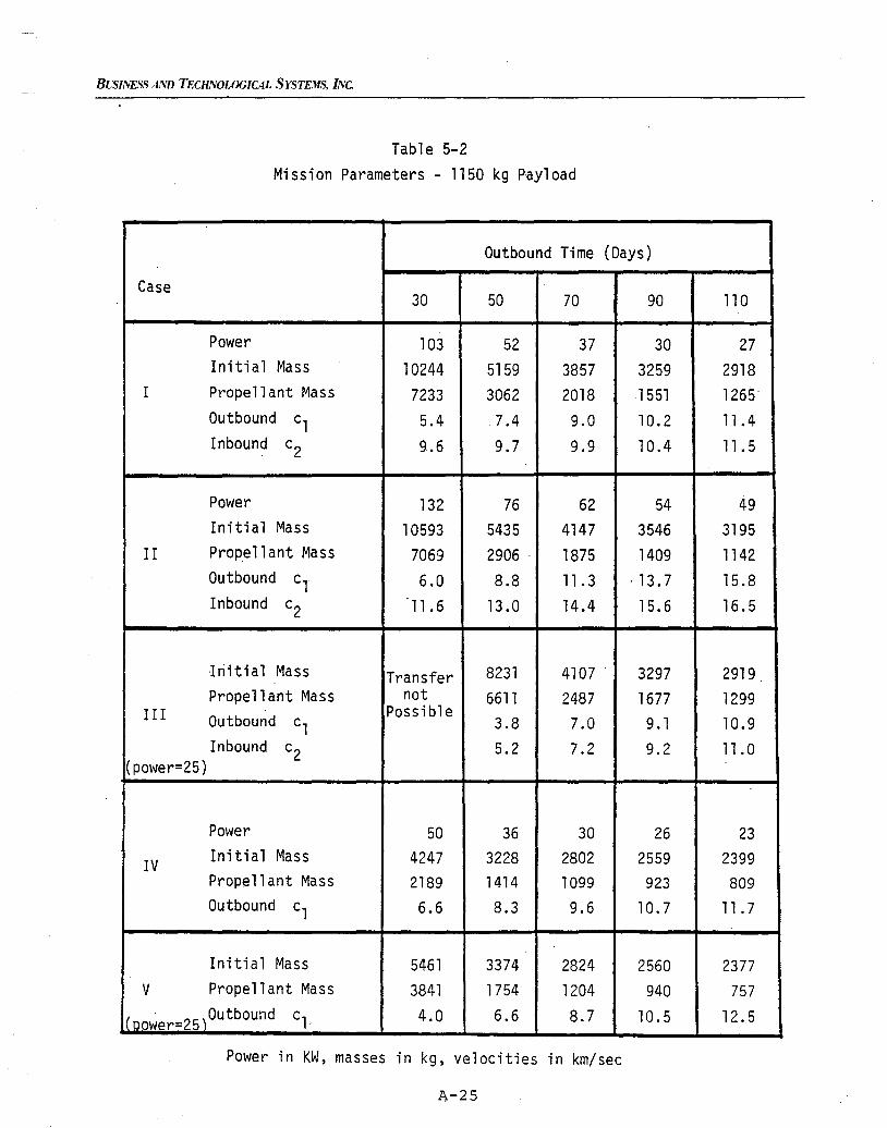
BL'SINESS AND TECHNOLOGICAL SYSTEMS, INC.
Table 5-2Mission Parameters - 1150 kg Payload
Outbound Time (Days)
Case30 50 70 90 110
Power 103 52 37 30 27Initial Mass 10244 5159 3857 3259 2918
I Propell ant Mass 7233 3062 2018 1551 1265'Outbound c1 5.4 7.4 9.0 10.2 11.4Inbound c2 9.6 9.7 9.9 10.4 11. 5
Power 132 76 62 54 49Initi alMass 10593 5435 4147 3546 3195
II Prope11 ant Mass 7069 2906 . 1875 1409 1142Outbound c, 6.0 8.8 11. 3 ·13.7 15.8Inbound c2 11.6 13.0 14.4 15.6 16.5
Initial Mass Transfer 8231 4107 . 3297 2919Propell ant Mass not 6611 2487 1677 1299
III Outbound Possible3.8 7.0 9.1 10.9c1
Inbound c2 5.2 7.2 9.2 11.0(power=25)
Pm'Jer 50 36 30 26 23
IV Init ialMass 4247 3228 2802 2559 2399Prope11 ant Mass 2189 1414 1099 923 809Outbound c1 6.6 8.3 9.6 10.7 11. 7
Initial Mass 5461 3374 2824 2560 2377V Propellant Mass 3841 1754 1204 940 757
'01' 25,Outbound c1· 4.0 6.6 8.7 10.5 12.5It ower=
Power in KH, masses in kg, velocities in km/sec
A-25
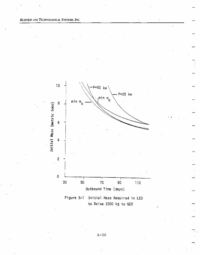
BUSI1VESS AIVD TECHNOLOGICAL SYSTEMS, INc.
10 JII
!;
- 8 I minV1 1c:0 I+.>
Iu I....S0-
l+.><1l 65-V1V1ttl I
:E: I..... 4 I
ttl -4....+.>....c:.....
2
a30 50 70 90
Outbound Time (days)
110
Figure 5-1 Initial Mass Required in LEOto Raise 2300 kg to GEO
A-26
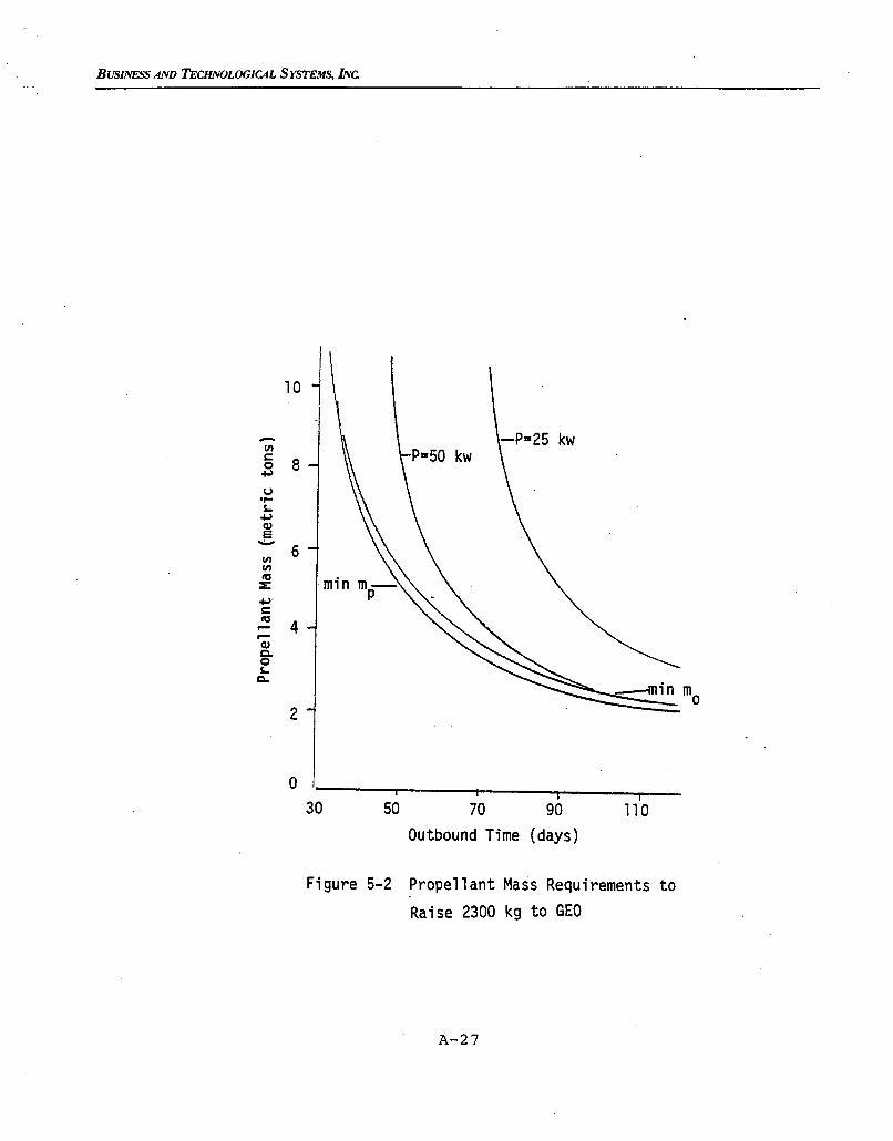
BUSINESS AND 'TECHNOLOGIC4L SYSTEMS, INc
10
- -P=25 kwVIe:
80+ol
U....$-+olQ.le.....
6VIVIttl
Z+ol'e:ttl
4........Q.lQ.0$-Q.
2
o30
i50 70 90
Outbound Time (days)
i110
Figure 5-2 Propellant Mass Requirements to
Raise 2300 kg to GEO
A-27
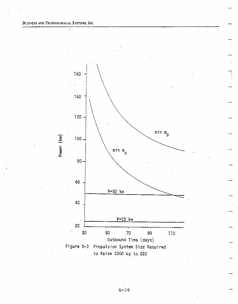
BLSINESS AND TECHll/OL0G1CAL SYSTEMS, INc
-3.:.::-s..(1J
3o0..
160 ..,IiI!
140 iI
120 l!
100JII
min mo
80
60
P=50 kw
40
P=25 kw20
30 50 70 90 110Outbound Time (days)
Figure 5-3 Propulsion System Size Requiredto Raise 2300 kg to GEO
A-28
.......,
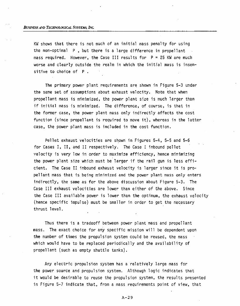
BUSINESS AND TECHNOLOOICAL SYSTEMS, INc.
KW shows that there is not much of an initial mass penalty for usingthe non-optimal P, but there is a large difference in propellantmass required. However, the Case III results for P = 25 KW are muchworse and clearly outside the realm in which the initial mass is insensitive to choice of P.
The primary power plant requirements ar~ shown in Figure 5-3 underthe same set of assumptions about exhaust velocity. Note that whenpropellant mass is minimized, the power plant size is much larger thanif initial mass is minimized. The difference, of course, is that inthe former case, the power plant mass only indirectly affects the costfunction (since propellant is required to move it), whereas in the lattercase, the power plant mass is included in the cost function.
Pellet exhaust velocities are s~own in Figures 5-4, 5-5 and 5-6for Cases I, II, and II respectively. The Case I inbound pelletvelocity is very low in order to maximize efficiency, hence mini.mizingthe power plant size which must be larger if the rail gun is less efficient. The Case II inbound exhaust velocity is larger since it is propellant mass that is being minimized and the power plant mass only entersindirectly, the same as for the above discussion about Figure 5-3. TheCase III exhaust velocities are lower than either of the above. Sincethe Case III available power is lower than the optimum, the exhaust velocity(hence specific impulse) must be smaller in order to get the necessarythrust level.
Thus there is a tradeoff between power plant mass and propellantmass. The exact choice for any specific mission will be dependent uponthe number of times the propulsion system could be reused, the masswhich would have to be replaced periodically and the availability ofpropellant (such as empty shuttle tanks).
Any electric propulsion system has a relatively large mass forthe power source and propulsion system. Although logic indicates thatit would be desirable to reuse the propulsion system, the results presentedin Figure 5-7 indicate that, from a mass requirements point of view, that
A-29
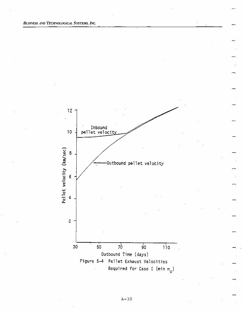
BUSINESS AND TECHIVOLOGICAL SYSTEMS, INc.
12
Inbound10 pellet velocit
-(,J
8(1)Vl
"-= Outbound pellet velocity~-~
-+-l....(,J 60....(1)
>-+-l(1)....
4....(1)
Q"
2
I I I
30 50 70 90 110Outbound Time (days)
Figure 5-4 Pellet Exhaust VelocitiesRequired for Case I (min rna)
A-30
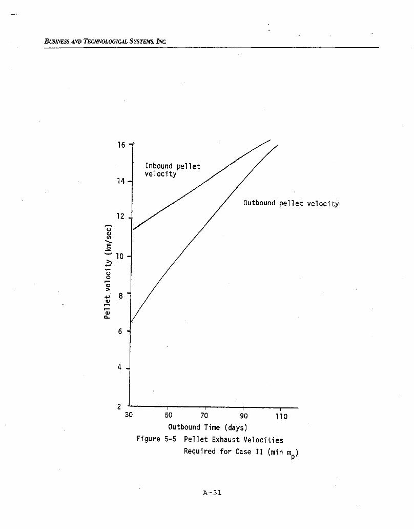
BUSINESS AND TECHNOLOGICAL SYSTEMS, INc
Outbound pellet velocity
Inbound pelletvelocity
12
16
14
-uQ)en"E..:lo:
- 10~....uo,...
: a ~Q),...,...cv
c..
6
4
230 50 70 90 110
Outbound Time (days)Figure 5-5 Pellet Exhaust Velocities
Required for Case II (min mp)
A-31
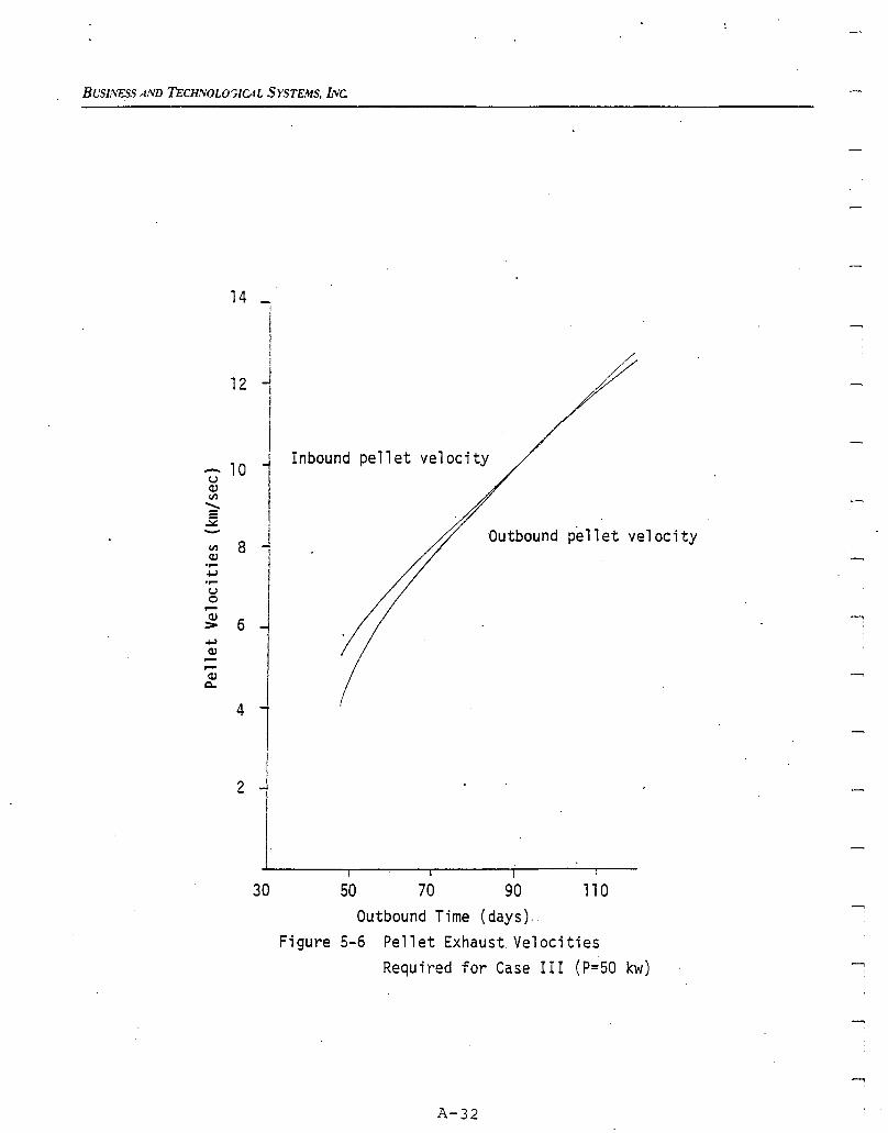
BL'S/t',ESS AND TECll'VOLOr;ICAL SYSTEMS, INc.
14
--,
Outbound p~llet velocity
Inbound pellet velocity
I50 70 90 11 0
Outbound Time (days).,Figure 5-6 Pellet Exhaust Velocities
Required for Case III (P=50 kw)
30
1I
2 j
Ij
J12 III
I
1!1
]- 10uQ)VI
........e~-VI 8Q),-
+oJ,-U0....Q)
6>+oJQ),....,....Q)
Q.
4
A-32
BUSINESS AND TECHNOLOGICAL SYSTEMS, INC.
more propellant mass is required to return the system to LEO than the massof a new (smaller) system for a one-way transfer. Figure 5-7 comparesthe propellant mass requirement for the round trip (Cases II and III)with the propellant plus propu;sion system masses (m + me) for the one-. pway trip (Cases IV and V). Both optimum (Cases II and IV) and fixed P(Cases III and V) results are shown. For shorter times of flight, thereis a clear advantage for the one-way transfer.
The propulsion system sizes and exhaust velocities correspondingto Figure 5-7 are shown in Figures 5-8 and 5-9 respectively. Less poweris required for the one~way transfer since the propellant for the returntrip does not have to be moved out and then back. This also means thatthe exhaust velocities can be higher to make more efficient use of thefuel. The requirements on P for outbound-only transfers have the
.additional feature that they are closer to the specified constraints(l0-50 KW).
-5.2 Comparison with BIMOD
It is interesting to compare the electric gun performance and requirements with the BIMOD thruster which is an ion propulsion system currentlyavailable for mission planning. The power plant mass for BIMOD is givenby
- (S)me - 35,42S MW P
which corresponds to one BIMOD thrusters for each 6252 watts~ BIMODoperates at constant exhaust velocity
C = 29.6 km/sec
and efficiency
n = .610
A-33
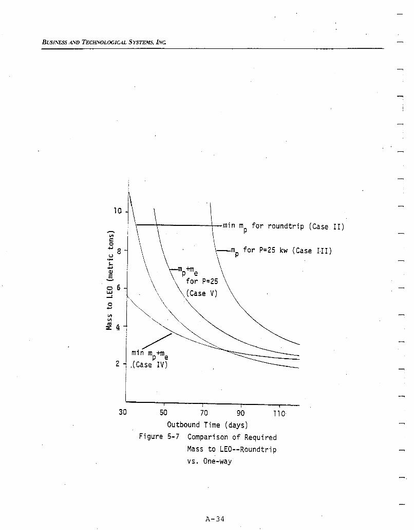
BVSIIVESS AND TECHNOLOGICAL SYSTEMS, INc
mp+mefor P=25
,,(Case V)
....s..
oI-ldl
=-o 6UJ...I
o.....VIVI
~4
2
\\
\
"" \~ \
''''~'. ""/~
min mp+me,(Case IV)
min mp for roundtrip (Case II)
-mp for P=25 kw (Case I-I I)
30 50 70 90 110Outbound Time (days)
Figure 5-7 Comparison of RequiredMass to LEO--Roundtripvs. One-way
A-34
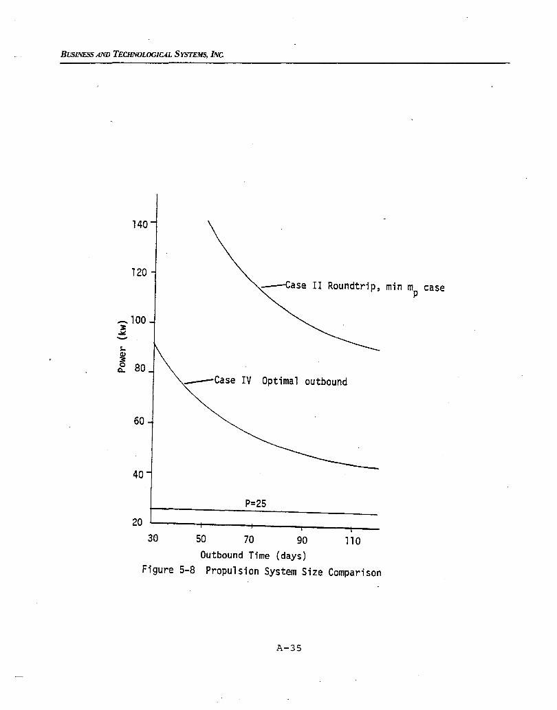
BUSINESS AND TECHNOLOGICAL SYSTEMS, INc
140
-----Case II Roundtrip, min mp case120
s..
~Q.. 80
_100J:-'"-
______Case IV Optimal outbound
60
40
P=25
20
30 50 70 90 110Outbound Time (days)
Figure 5-8 Propulsion System Size Comparison
A-35
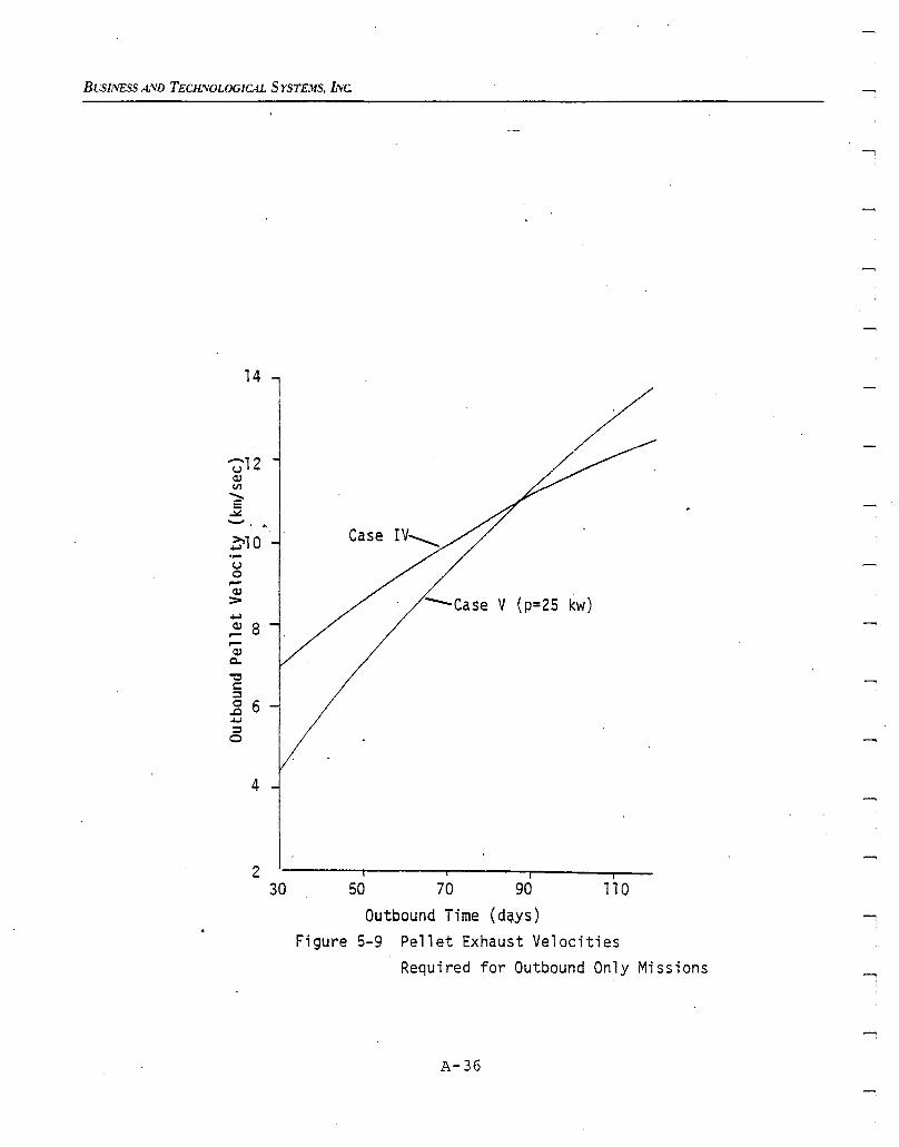
Busu,,'ESS AND TECHNOLOGICAL SYSTEMS, INc
14 lI
/'Z?12
C1JV1......E~-~10....u0.--C1J::-+-lC1J 8.--
.--C1J
Q.
"'0c::;:,0 6..c+-l:;:,
0
4
2 i i
30 50 70 90 110Outbound Time (dqys)
Figure 5-9 Pellet Exhaust VelocitiesRequired for Outbound Only Missions
A-36
, BUSINESS AND TECHNOLOGICAL SYSTEMS, INC.
The SIMOO operates more efficiently at a higher exhaust velocity thanthe electric gun*. However, it has a much heavier power plant whichmust be moved.
The comparison between electric gun and SIMOO initial mass andpower requirements are shown in Figures 5-10 and 5-11 respectively foroutbound-only transfers. The SIMOO, with its higher efficiency andexhaust velocity, can accomplish the transfer with a smaller mass onlyfor very long transfers. For shorter transfer, the electric gun isclearly superior. Whereas, the electric gun could accomplish the transferin less than twenty days, the SIMOO cannot accomplish the transfer inless than sixty days. The results presented here have assumed thatany size system with the SIMOO characteristics could be used. The 'factthat integral numbers of individual SIMOO units must be selected isreflected in the stair-step curve alongside the ideal power requirementin Figure 5-11.
Since SIMOO has a fixed exhaust velocity, constraining. the rowerplant size implies the transfer time. With 50 KW (8 SIMOO units) ~he
transfer could be accomplished in 120 days. With 25 KW (4 SIMOO units)it would take 185 days.
The rail gun has an additional advantage over SIMOO in that itspropellant is "l ess expensive". As pointed out by OINeill (Reference10), the space shuttle tanks can be carried into low earth orbit withthe shuttle, at the expense of reducing the shuttle payload by anamount equal to less than four percent of the tank mass. Thus, eventhough the rail gun uses more propellant mass than SIMOO for longertimes of flight, it is still superior since its reaction mass canbe put in low earth orbit at a "l ower cost". In order for BIMOO or
any other ion ,propulsion system to be competitive with the rail gun,the propulsion system would have to be as light as the rail gun withthe high efficiencies of the best ion propulsion system and very high(by current standards) exhaust velocities (specific impulse).
* There is no advantage in decreasing the SIMOO exhaust velocity sincethe efficiency also decreases such that thrust is also lower. Decreasingelectric gun exhaust velocities results in higher thrust--when it isneeded.
A-37
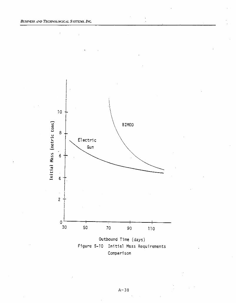
BUSINE_ AND TECHNOLOGICAL _ YSTEMS, .[NC,.
2 _
i
0 I 1 1 I30 50 70 90 II0
OutboundTime (days)
Figure5-10 InitialMass Requirements
Comparison
A-38
[--
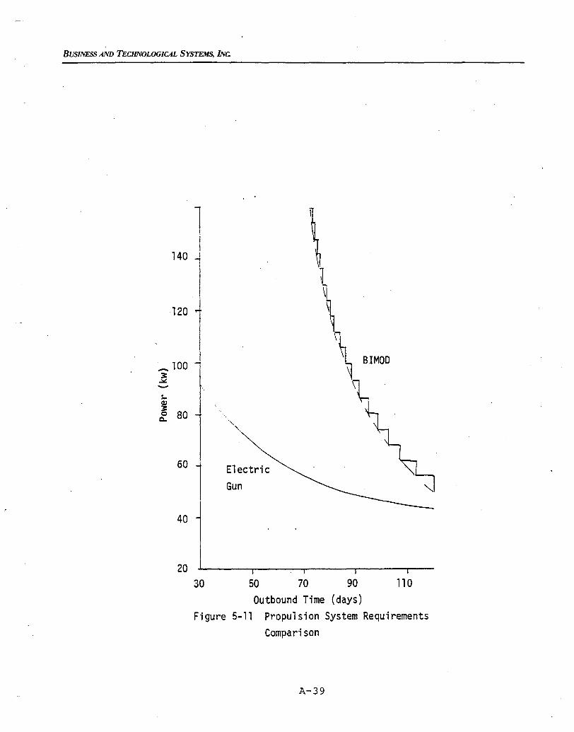
BUSINESS AND TECHNOLOGIC4L SYSTEMS, INc.
1IjI
140 I,-.JIIII
120 1II,I l SIMOO_ 100
~..:loI:
'l-s..Q)~0 80Q.
"-"-
60 ElectricGun
40 .
11050 70 90
Outbound Time (days)Figure 5-11 Propulsion System Requirements
Comparison
20
30
A-39
Bl.S1SESS AND TECILVOLOGICAL SYSTEMS, INC.
5.3 Comparison with Inertial Upper Stage (IUS)
Another alternative propulsion system is the chemical-rocket Inertial Upper Stage (IUS). For coplanar transfers between circular orbits,the optimal transfer with the impulsive IUS is the classical Hohmanntransfer with one impulse at perigee and a second impulse at apogee
of an elliptic transfer orbit.
The IITwo-Stage ll IUS is basically sized for the transfer of a 2300kg payload, the desired size for this study, from LEO to GEO with aplane change to equatorial orbit at GEO.
The basic energy equation for orbits
(5- 1 )
provides the information about the necessary IUS velocity increment at perigee,
~vl ' and apogee, ~v2' The orbital parameters presented in Table4-1 approximately represent the LEO to GEO parameters using ~ = 60(in the units of Table 4-1). The velocity on the initial circular orbit
must be increased to the intermediate elliptic orbit
2 2 1v .= ~(- - -) •1 aO al
Then the velocity at apogee on the elliptic orbit
2 2 1v . = ~(- - -)2 af al
must be increased to the final circular orbit ve19city
V2 = L
. f af
A-40
(5-2)
( 5-3)
(5-4)
(5-5)
BUSINEsS AND TECHNOLOGICAL SYSTEMS, INC.
where
The required velocity increments are
~vl = vl - Vo = 2.437 km/sec
~v2 =vf - v2 = 1.471 km/sec
The IUS with the parameters given in Table 5-3 , (as described inthe documentation provided by NASA LeRC) is capable of providing
~v = 1.679 km/sec2IUS
which is more than needed. However, provlslon is apparently not madeto off-load fuel from the second stage, so some fuel would be wasted.The first stage woul~ then only be able to yield
~V = 2.425 km/sec1IUS
which is not quite the required amount.
It is thus concluded that the transfer parameters used for thisstudy are not quite the same as the parameters used to establish theIUS as an adequate vehicle for LEO to GEO transfers. For comparisonwith the transfer considered in this report, compare the entire IUSfirst stage (10,886 kg), se~ond stage (3856 kg) and payload (2300 kg)to yield
mO =17,042 kg .
The electric rail gun has a lower initial mass for all transferslonger than about 30 days. Further, for relatively small increases in
A-41
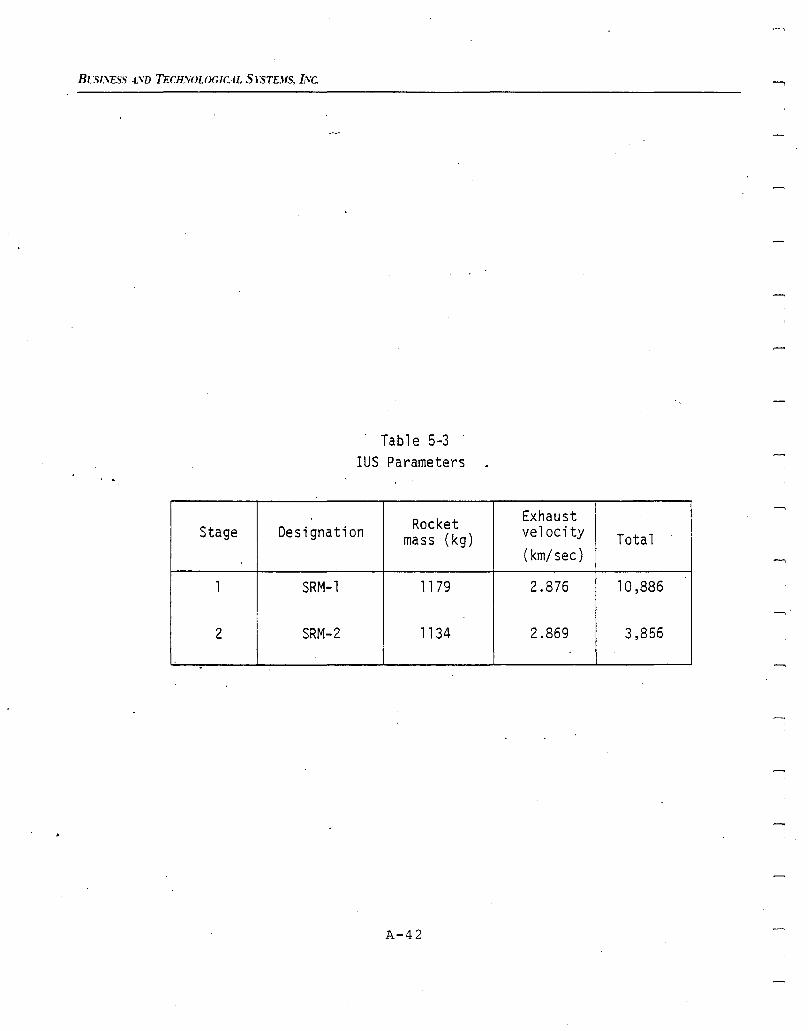
BLS/;\ESS 4.\'D TECH.'YOLOGICAL SYSTEJIS, L'Ve.
Tabl e 5-3IUS Parameters
Rocket ExhaustStage Designation mass (kg) velocity Total
(km/sec)
1 SRM-l 1179 2.876 10,886
2 SRM-2 1134 2.869 3,856
.
A-42
BUSINESS AND TECHNOLOGICAL SYSTEMS, INC.
the time nf flight, the rail gun masses drop dramatically. Thus,it must be concluded that the IUS only has an advantage for very shorttransfer times or, in the event that there is a substantial capitalcost differential.
For the rocket mass and exhaust velocities given, the initial masswould be given by
1.471 2.437
mO
= (1179 + (2300 + 1134)e2•869 ) e 2 .876
= 16,132 kg
if the IUS stages were free to be independently specified. Even forthis lower initial mass, the rail gun provides superior performancefor all but very short transfer times.
A-43

A-44
.....,
Bl/SII\'ESS AND TECHNOLOGICAL SYSTEMS, INC.
6.0 CONCLUSIONS AND RECOMMENDATIONS
All study objectives have been satisfied. The electric rail gun has beenshown to provide a promising means of raising large payloads from LEO toGEO -- and in very short times relative to those achievable using BIMODthrusters. The relatively small propulsion system mass more than compensates for a specific impulse and efficiency which are lower than forBIMOD. The rail gun provides a lower mass in LEO than the InertialUpper Stage (IUS) for transfers longer than 15 days.
Further studies are clearly indicated. The effect upon propellantmass requirements of constraining the pellet exhaust velocity (so thatno pellets remain in earth orbit) should be determined. In addition,there are a number of further investigations indicated which shouldexplore the interrelationship between mission objectives and thecharacteristics of the rail gun. The studies to date have not fullyexplored and minimized the true costs of the system. The size and life-,time of a pellet processor are an important cost which has not beenevaluated. Further, these studies have assumed the power supply andpropulsion system were being reused many times. The finite (different)lifetimes of major components should be factored in. Finally, it hasbecome apparent that, although theoretically possible, variation of railgun exhaust velocity carries with it a penalty in efficiency. Thus, waysto vary the specific impulse without the efficiency penalty need to beexplored. Once all of these effects have been modelled, optimizationcan be performed to determine the ~est choice of propulsion system parameters, given a more complete statement of cost involved.
A-45

A-46
BUSINESS AND TECHNOLOGICAL SYSTEMS, INC.
7.0 REFERENCES
(1) Barber, J. P., "Electric Rail Gun Application to Space Propulsion",AIAA Paper No. 79-2091, Princeton, NJ, 1979.
(2) Sharp, G. R., J. E. Cake, J. C. Oglebay, and F. J. Shaker, MassStudy for Modular Approaches to a Solar Electric Propulsion Module,Technical Memorandum NASA TM X-3473, Lewis Research Center, March,1977 .
(3) Vahlberg, C. Julian, Electric Gun Mission Analysis Results, ReportBTS-FR-127, Business and Technological Systems, Inc., September1980.
(4) Vahlberg, C. J., and T. N. Edelbaum, "Transfers Between CoplanarCoaxial Ellipses Using the Combination of High- and Low-ThrustPropulsion", AIAA Paper No. 71-368, Ft. Lauderdale, 1971.
(5) Leitmann, G., Ed., Optimization Techniques, Academic Press, N.Y.,1962.
(6) Edelbaum, T. N., "0timal Power Limited Orbit Transfer in StrongGravity Fields ll
, AIAA J., Vol. 3, No.6, 1965.
(7) Edelbaum, T. N., "propulsion Requirements for ControllableSatellites", American Rocket Society Journal, August 1961.
(8) Barber, J. P., and D. P. Bauer, Rail Gun Propulsion System MassPreliminary Estimates, Technical Memorandum IAP-TM-79-002,International Applied Physics Inc., October, 1979.
(9) Bauer, D. P., personal communication" International Applied PhysicsInc., October 1980
(10) OINeill, G. K., liThe Low (Profile) Road to Space Manufacturing",Astronautics and Aeronautics, March 1978.
A-47
BUil.VESS .-tVD TECff¥OLOGICAL SYSTE.US. INC.
(11) Sackett, L. L., H. L. Malchow, T. N. Edelbaum, Solar ElectricGeocentric Transfer with Attitude Constraints: Analysis, NASACR-l34927 (Draper Lab R-901), The Charles Stark Draper Laboratory,
Inc., August, 1975.
(12) Sackett, L. L., and T. N. Edelbaum, Solar Electric GeocentricTransfer With Attitude Constraints: Program Manual, Report R-902,The Char1e~ Stark Draper Laboratory, Inc., August, 1975.
A-48
BUSINESS AND TECHNOLOGICAL SYSTEMS, INC.
Appendix AA
COMPARISON OF ANALYTIC PREDICTION WITH NUMERICAL INTEGRATIONS
In a previous study (Reference 3), the analytic results presentedin Chapters 2 through 4 have been compared with the output of the ~olar
Ilectric lontrol !nob~etting frogram for Qptimal Irajectories (SECKSPOT).(References 11,12) SECKSPOT numerically integrates the equations ofmotion under the assumption of fixed power and constant specific impulse.The program iterates to find the minimum time of flight which accomplishesthe transfer. SECKSPOT also has the ability to include the oblatenesseffects upon gravity, the shadowing effects on solar cell power output,
< and the solar cell damage due to radiation.
The results of comparing SECKSPOT and the analytic results areshown in Table A-l. As expected, the two results are identical 'iT thereis no plane change and no shadowing. Results are surprisingly closewhen an inclination change is considered, given the approximations discussedin Section 3.3. Shadowing principally causes a longer transfer timewith a small increase in ~u (propellant) required. Essentially thesame change in ~u requirements were obtained over a range of flighttimes. Changes in time of flight were basically. proportional to thenominal time of flight.
Although SECKSPOT has the ability to determine the effects of solarcell degradation due to radiation damage, no results have been obtainedto date for these transfers. Initial attempts during the first phaseof the referenced effort used shield thicknesses which, although reasonablefor the newer GaA1As solar cells, would result in almost instantaneousdestruction of the silicon cells which are modeled in SECKSPOT. Duringthe second phase, a solar cell shield thickness which would make silicon
. .cell degradation equivalent to GaA1As with a thinner shield was tried.That resulted in numerous underflows, overflows, and divide checks sincethe equivalent shield was so thick. Intermediate values were tried withonly moderate success before the available resources were depleted.
A-49
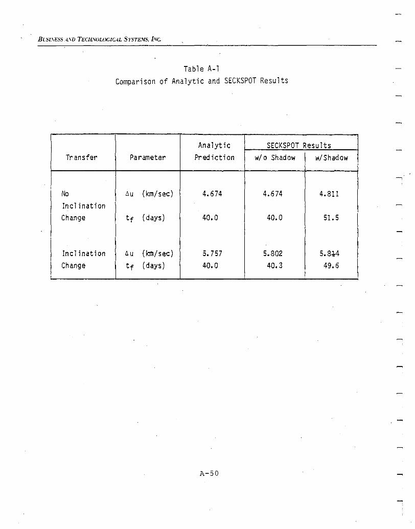
BLSI.\ESS ASD TEClLVOLOGICAL SYSTEMS, INC.
Table A-lComparison of Analytic and SECKSPOT Results
Analytic SECKSPOT ResultsTransfer Parameter Pre<! icti on wi 0 Shadow w/Shadow
No Liu (km/sec) 4.674 4.674 4.811Incl inationChange tf (days) 40.0 40.0 51. 5
Incl ination Liu (km/sec) 5.757 5.802 5.8~-4
Change tf (days) 40.0 40.3 49.6
A-50
BUSINESS AND TECHNOLOGICAL SYSTEMS, INC
In both phases of that project the task was made more difficult dueto problems with the iteration to find the minimum time solution. SECKSPOTrequires an initial guess for the costates, it calculates the optimal transfer(to the wrong final conditions), and then iterates on the initial costatein order to reach the desired final condition. Two distinct problems havebeen encountered with the iteration. Although neither problem affectsthe final answer if the iteration converges (since the integration iscorrect), both problems affect the cost in obtaining convergence.
The first problem is with non-linearities in the optimal control problembeing solved. The iterator is seeking the minimum (zero) of the sum ofthe squares of the errors in the orbit at the final time. However, theiterator gets trapped i~ local, non-zero minima which are not in thesolution. Offsetting the initially guessed costates usually solves theproblem. However, the program takes a lot of computer time to recognizethat it is trapped and repeated trials have proven to be more expensivethan expected.
The second problem is wi~h the iteration algorithm itself. Althoughconvergence is rapid once close to the solution, the algorithm has difficulty both in the early stages of the iteration and in recognizing whenit is trapped at a local minimum. Other iterations are available whichare, in fact, compatible with the SECKSPOT structure. They promise asolution to the above problems and should be able to find the minimum withfewer function evaluations (integrations along the optimal trajectory).
Although straightforward to implement, it cannot be guaranteed thatother algorithms would resolve the problem of local minima. However, theywould allow more trials to determine better initial costates. Unfortunately,such program changes are beyond the scope of this current effort and cannotbe pursued within current project resources.
A-51

A-52
.....,
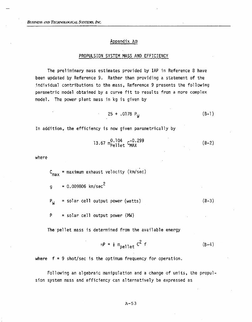
BUSINESS AND TECHNOLOGICAL SYSTEMS, INC.
Appendix AB
PROPULSION SYSTEM MASS AND EFFICIENCY
The preliminary mass estimates provided by lAP in Reference 8 havebeen updated by Reference 9. Rather than providing a statement of the.individual contributions to the mass, Reference 9 presents the followingparametric model obtained by a curve fit to results from a more complexmodel. The power plant mass in kg is given by
25 + .0178 Pw
In addition, the efficiency is now given parametrically by
13 67 0.104 C-0.299. mpell et MAX
where
Cmax = maximum exhaust velocity (km/sec)
(B-1)
(B-2)
g = 0.009806 km/sec2
Pw = solar cell output power (watts)
P = solar cell output power (MW)
The'pellet mass is determined from the available energy
2nP = t mpellet C f
where f =9 shot/sec is the optimum frequency for operation.
(B-3)
(B-4 )
Following an algebraic manipulation and a change of units, the propulsion system mass and efficiency can alternatively be expressed as
A-53
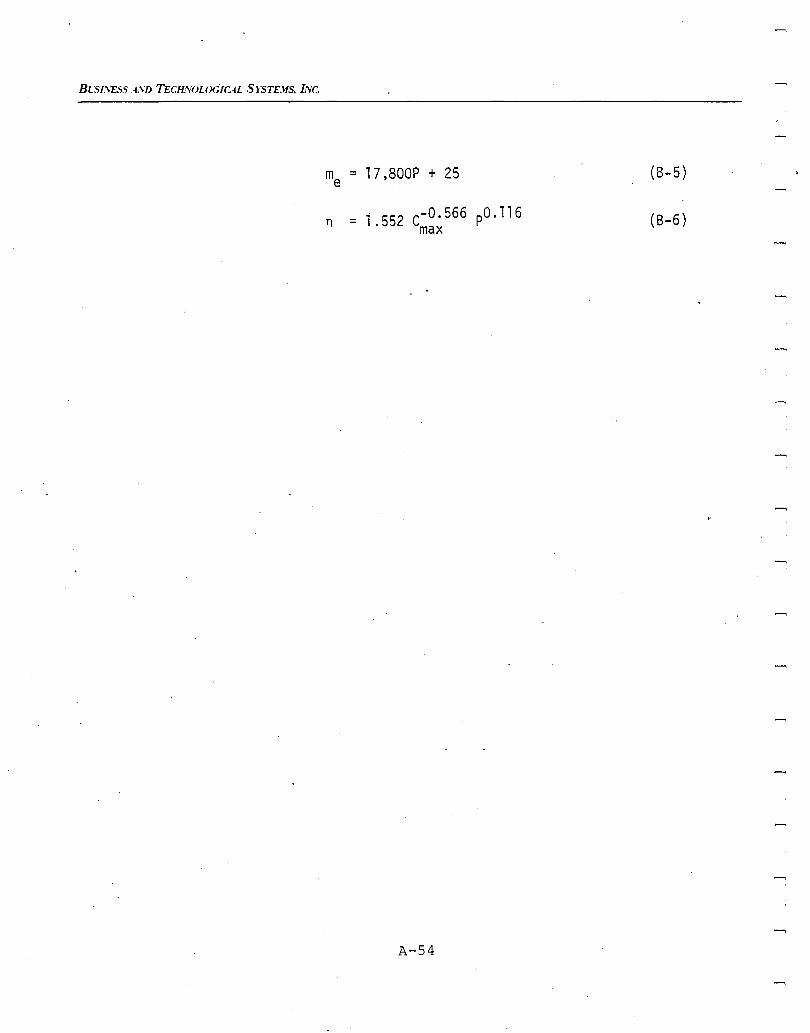
BC'>l.'ESS 4SD TECHNOLOGICAL S 15TDfS, I'Ve.
me = 17,800P + 25 (8-5 )
n = 1 552 C-O. 566 pO.116. max
A-54
(8-6)
BUSINESS AND TECHNOLOGICAL SYSTEMS, INc.
Appendix AC
GLOSSARY OF SYMBOLS
The symbols used in this report. are summarized in this appendix.They are logically grouped into three'categories.
Orbital Parameters
A = Thrust acceleration from the propulsion system
a = semi-major axis of the orbit
i = inclination of the orbital plane
k = intermediate variable for description of the orbitalelements
t f = total transfer time between orbits
v = mean orbita] speed of the spacecraft in the orbit
~u = equivalent change in spacecraft velocity caused by thepropulsion system
S = the angle between the thrust vector and the orbital plane.
s = the mean anomaly (position angle)
~ = gravitational constant
A-55
BLSI.\ESS .4.\D TECH.VOLOGICAL S rSTEJfS. INC.
Propulsion System Parameters
c = fuel exhaust velocity ~ a .
P = total power provided by power supply.
n = propulsion system efficiency.
Mass Expressions
~u
E = e2c
= parameter used to describe mass change during constantexhaust velocity thrusting
t
=1 f A~()) ds2 n sa
= parameter used to describe mass charge during optimal
exhaust velocity thrusting
m = total spacecraft mass
m = rate of depleting fuel
ma = initial total mass in LEO
= me + m + mIT p
me = mass of propulsion system including solar cells, powerconditioning,rail gun, etc.
A-56

BUSINESS AND TECHNOLOGICAL SYSTEMS, INC
= total propellant mass expended for the mission,~,
m1T
= mass of payload.
A-57