Embed Size (px)
Citation preview
NASA GRC Cyclotron Decommissioning Project Work Execution Package
Work Execution Package Title
Building 140 Radiological Survey Only
WEP Number WEP-16-002
Revision # 1
Effective Date 2/3/17
DOCUMENT CONTROL STAMP
Title Signature Date
Originator Dustin G. Miller 2/3/17
Independent Technical Reviewer Dave Culp 2/3/17
Supervisory Review
Project Radiation Safety Officer
IMPLEMENTATION APPROVAL
NASA Cyclotron Decommissioning Project Manager
CLOSE OUT APPROVAL
Responsible Manager
D. Scott Minerd 2/3/17

NASA GRC CYCLOTRON DECOMMISSIONING PROJECT CHANGE/CANCELLATION RECORD
DOCUMENT TITLE:
Building 140 Radiological Survey Only
DOCUMENT NO:
WEP-16-002 REVISION NO:
1
Revision 0: Initial issue of Document
Revision 1: Revions of Fall Protection Plan.

LIST OF EFFECTIVE PAGES
DOCUMENT NO: WEP-16-002 REVISION NO.: 1
Page No. Revision Level Page No. Revision Level Page No. Revision Level
Cover Rev 1
Change Record Rev 1
LOEP Rev 1
Pages 1 thru 43 Rev 0
App A Cover JHA
Rev 0
App A Pages 1 thru 15
Rev 0
App B Cover Dose Model Reports
Rev 0
App B Dose Model Reports Pages 1 thru 15
Rev 0
Att A Cover Fall Prev Plan
Rev 1
Att. A Pages 1 thru 2
Rev 1
Add A Cover Daily Activities
Rev 0
Add. A Pages 1 thru 3
Rev 0

GRC Cyclotron Decommissioning Project Work Execution Package
Work Execution Package Number: WEP-16-002 Revision No. 0
Page 1 of 43
TABLE OF CONTENTS 1.0 INTRODUCTION.................................................................................................. 5 2.0 FACILITY DESCRIPTION ................................................................................. 6 3.0 SITE OPERATING HISTORY ............................................................................ 7 4.0 NUCLIDES OF CONCERN ................................................................................. 7 5.0 RADIOLOGICAL STATUS OF FACILITY ...................................................... 7 6.0 RELEASE CRITERIA .......................................................................................... 9 7.0 DERIVED CONCENTRATION GUIDELINE LEVELS (DCGL) .................. 9 8.0 ALARA GOALS .................................................................................................. 12 9.0 WORK PLAN LIMITATIONS .......................................................................... 12 10.0 NOTIFICATIONS ............................................................................................... 13 11.0 PLANNED REMEDIATION ACTIVITIES ..................................................... 13 12.0 MANAGEMENT ORGANIZATION ................................................................ 13
12.1 NASA Radiation Safety Officer (NASA RSO) ................................................. 13 12.2 Chase Project Manager....................................................................................... 14 12.3 Radiation Protection manager ............................................................................ 15 12.4 Radiation protection Technicians ....................................................................... 15 12.5 Radiation Workers.............................................................................................. 15
13.0 PROJECT TRAINING REQUIREMENTS...................................................... 16 13.1 Radiological Training ......................................................................................... 16 13.2 Project Specific Training .................................................................................... 16 13.3 General Safety Briefings .................................................................................... 17 13.4 Visitor Orientation.............................................................................................. 17 13.5 Transportation Training...................................................................................... 17
14.0 PROJECT TASK MANAGEMENT .................................................................. 17 15.0 RADIATION PROTECTION ............................................................................ 17
15.1 Radiation Work Permits (RWP) ......................................................................... 17 15.2 Dosimetry ........................................................................................................... 18 15.3 Air Sampling ...................................................................................................... 18 15.4 Personal Protective Equipment .......................................................................... 18
16.0 RADIOACTIVE MATERIALS MANAGEMENT .......................................... 18 17.0 QUALITY ASSURANCE PROGRAM ............................................................. 18
17.1 Nonconformance Control and Corrective Action .............................................. 19 17.2 Sample Chain-of-Custody .................................................................................. 20 17.3 Quality Assurance Surveys ................................................................................ 20
18.0 SURVEY INSTRUMENTATION ...................................................................... 20 18.1 Instrumentation Specifications ........................................................................... 20 18.2 Minimum Detectable Concentrations................................................................. 22 18.3 Static Counting ................................................................................................... 22 18.4 Ratemeter Scanning - Surface ............................................................................ 23 18.5 Ratemeter Scanning – Volumetric MDC ........................................................... 24 18.6 Smear Counting .................................................................................................. 27
19.0 SURVEY DOCUMENTATION ......................................................................... 28

GRC Cyclotron Decommissioning Project Work Execution Package
Work Execution Package Number: WEP-16-002 Revision No. 0
Page 2 of 43
20.0 CHARACTERIZATION SURVEYS ................................................................. 28 21.0 REMEDIAL ACTION SURVEYS ..................................................................... 29 22.0 FINAL STATUS SURVEYS ............................................................................... 29
22.1 Background Determination ................................................................................ 30 22.2 Data Quality Objectives ..................................................................................... 30 22.3 Area Classifications............................................................................................ 31
22.3.1 Non-Impacted Area ..................................................................................... 31 22.3.2 Impacted Areas ........................................................................................... 31
22.4 Survey Units ....................................................................................................... 32 22.5 Surface Scans ..................................................................................................... 33 22.6 Total Surface Activity Measurements ................................................................ 33 22.7 Dose Rate Measurements ................................................................................... 34 22.8 Solid Samples ..................................................................................................... 34 22.9 Number of Samples ............................................................................................ 34
22.9.1 Determination of the Relative Shift ............................................................ 35 22.9.2 Determination of Acceptable Decision Errors ............................................ 35 22.9.3 Number of Data Points for Surface Activity (Sign Test) ............................ 36 22.9.4 Number of Data Points for Volumetric Activation (WRS Test)................. 36
22.10 Sample Locations ............................................................................................... 38 22.11 Removable Contamination Measurements......................................................... 38 22.12 Surveys of Building Mechanical System Internals ............................................ 39 22.13 Survey Investigation Levels ............................................................................... 39
23.0 INTERPRETATION OF SURVEY RESULTS ................................................ 39 23.1 Data Validation .................................................................................................. 40 23.2 Preliminary Data Review ................................................................................... 40 23.3 Determining Compliance for Surface Activity .................................................. 40 23.4 Determining Compliance for Volumetric Activity ............................................ 41
24.0 MECHANICAL SYSTEM SURVEY DATA ANALYSIS ............................... 42 25.0 ALTERNATE SCENARIO ANALYSIS ........................................................... 42 26.0 RADIOLOGICAL SURVEY REPORT ............................................................ 43 27.0 REFERENCES ..................................................................................................... 43

GRC Cyclotron Decommissioning Project Work Execution Package
Work Execution Package Number: WEP-16-002 Revision No. 0
Page 3 of 43
TABLES Table 5-1: Cyclotron Vault Concrete Core Results Summary (Leidos 2016) .................... 8 Table 7-1: Surface Activity DSVs ................................................................................... 10 Table 7-2: Removable Activity Contribution to Total Dose ........................................... 11 Table 7-3: Summary of DCGLs ....................................................................................... 11 Table 18-1: Instrumentation Specifications ...................................................................... 21 Table 18-2: Typical Instrument Operating Parameters ..................................................... 22 Table 18-3 –NaI Detector Response (cpm per μR/hr) for Eu-152 in Concrete ................ 26 Table 18-4 – NaI Scan MDC: Concrete, 12,000 cpm bkg, 5”/s scan rate @ 2” distance . 27 Table 22-1: Survey Investigation Levels ......................................................................... 39 Table 23-1: Sign Test Summary of Statistical Tests ......................................................... 41 Table 23-2: WRS Summary of Statistical Tests ............................................................... 42
APPENDICES
Appendix A: Job Hazard Analysis Appendix B: DandD Dose Model Reports
ADDENDUMS Addendum 1: Daily Activities Plan

GRC Cyclotron Decommissioning Project Work Execution Package
Work Execution Package Number: WEP-16-002 Revision No. 0
Page 4 of 43
ACRONYMS
ALARA As Low As Reasonably Achievable DAC Derived Air Concentration
DCGLEMC Derived Concentration Guideline Level – Elevated Measurement Comparison
DCGLW Derived Concentration Guideline Level – Wilcoxon Rank Sum DQO Data Quality Objective DOT Department of Transportation DSV Default Screening Value EPA US Environmental Protection Agency GRC Glenn Research Center H0 Null Hypothesis HA Alternative Hypothesis HEPA High Efficiency Particulate Air (Filter) HSA Historical Site Assessment MARSSIM Multi-Agency Radiation Survey and Site Investigation Manual MDC Minimum Detectable Concentration NASA National Aeronautics and Space Administration NARM Naturally-Occurring and Accelerator-Produced Radioactive Material NIST National Institute of Standards and Technology NRC U.S. Nuclear Regulatory Commission PIC Pressurized Ion Chamber PM Project Manager PPE Personal Protective Equipment RPM Radiation Protection Manager RPP Radiation Protection Program RPT Radiation Protection Technician RSM Radiation Safety Manual RWP Radiation Work Permit TEDE Total Effective Dose Equivalent TLD Thermoluminescent Dosimeter USEI US Ecology Idaho WAC Waste Acceptance Criteria

GRC Cyclotron Decommissioning Project Work Execution Package
Work Execution Package Number: WEP-16-002 Revision No. 0
Page 5 of 43
1.0 INTRODUCTION The National Aeronautics and Space Administration (NASA) has decided to decommission Building 140, a radioactive material usage location under their byproduct Nuclear Regulatory Commission (NRC) license number 34-00507-16. The facility contains a 69-inch cyclotron within a shielded vault and various support areas. NASA has contracted with Chase Environmental Group, Inc. (Chase) through Pinnacle Construction and Development Corporation (Pinnacle) to remove the cyclotron and decommission areas that are impacted for activation products; i.e., the vault and soils surrounding the vault. Upon completion of the decommissioning process and unrestricted release of the building and surrounding soils, the building will be demolished and sent for disposal along with surrounding soils. The cyclotron is located within a vault below grade at the NASA Glenn Research Center (GRC), Lewis Field in Cleveland, OH adjacent to the Cleveland Hopkins International Airport. The facility was constructed by General Electric in the late 1940’s and early 1950’s. The facility was turned over to NASA (NACA at that time) for operation in 1955. The cyclotron was permanently shutdown in 1990 and the facility is currently in a possession only status on the NASA GRC limited scope specific license. The unshielded 69” cyclotron will be removed as radioactive waste by Chase Environmental Group (Chase). Cyclotron removal will be performed under NASA’s AD-01(CYC) Rev 1, Creation, Revision, Approval, and Cancellation of GRC Cyclotron Decommissioning Project Plans, Procedures, and Documents. Based on gamma spectroscopy results from concrete core samples collected during facility characterization, inner portions of the concrete vault contain detectable levels of Co-60, Eu-152, Eu-154, and Na-22. This Plan was developed to provide the protocols for the radiological survey of the Cyclotron Vault and associated cyclotron beam paths to develop the radiological dose models that will support NASA’s request for unrestricted use of Building 140 and surrounding soils from the NASA radioactive materials license. The Plan was developed using the guidance provided in NUREG-1757, “Consolidated NMSS Decommissioning Guidance” and NUREG-1575, “Multi-Agency Radiation Survey and Site Investigation Manual” (MARSSIM); and provides the approach, methods, and techniques for radiological survey of the area. These methods ensure technically defensible data are generated to aid in determining compliance with the criteria for unrestricted use specified in 10 CFR 20 Subpart E. Portions of the concrete structure and/or other metallic items may require removal to meet the criteria for unrestricted use. Chase will remediate activated building structures as necessary to meet the release criteria and perform radiological surveys

GRC Cyclotron Decommissioning Project Work Execution Package
Work Execution Package Number: WEP-16-002 Revision No. 0
Page 6 of 43
in the cyclotron vault and in the associated beam tubes to demonstrate compliance with the release criteria. Chase will use existing characterization data collected by NASA to demonstrate that surrounding soils meet the unrestricted release criteria. Radiological work will be performed under the NASA GRC radioactive materials license. All activities will be performed in accordance with this Plan, NASA GRC Radioactive Materials License, and NRC regulations. On-site activities are expected to be performed in parallel with the removal of the cyclotron from Building 140. A job hazard analysis is included in Appendix A.
2.0 FACILITY DESCRIPTION The cyclotron vault has a footprint of approximately 1,800 square feet and is shown in Figure 2-1. The Cyclotron Vault (shaded green) and the embedded pipes/beam tubes (shaded red) are to be surveyed by Chase. There are other various rooms located within the NASA controlled area that will be surveyed for unrestricted release by NASA subcontractor, Leidos.
Figure 2-1: Facility Floor Plan

GRC Cyclotron Decommissioning Project Work Execution Package
Work Execution Package Number: WEP-16-002 Revision No. 0
Page 7 of 43
3.0 SITE OPERATING HISTORY The cyclotron was constructed by GE in the 1940’s and 1950’s and was first operated in 1955. The cyclotron was upgraded in the 1970’s from a 60” to a 69” cyclotron. The facility was also upgraded several times to include neutron therapy and additional spacing. NASA operated the facility and cyclotron until 1990 for research purposes. NASA contracted Leidos to support decommissioning of the facility. Leidos personnel have supported NASA with facility characterization and removal of activated and radioactively contaminated equipment and materials except for the remaining cyclotron components, embedded piping, overhead crane, and building structures.
4.0 NUCLIDES OF CONCERN Contaminants include activation products from cyclotron operations. Short lived radioisotopes have been mathematically eliminated from concern as they have had sufficient time to decay since shutdown. A cores sample was collected from the floor in the activated regions of concrete near the cyclotron. The detected radionuclides include Co-60, Eu-152, Eu-154, and Na-22.
Co-60 is the only nuclide of concern for remaining cyclotron components, steel I-beams and rebar in the floor, and steel piping/equipment.
Small quantities of H-3 are produced in the cooling water of the coils, however the H-3 is confined to the hollow cooling coils. The water has been removed from the coils. Removable tritium measurements were performed during initial facility characterization. The tritium smears were collected in the most likely locations for contamination and were counted by liquid scintillation counting with all results less than 200 dpm/100 cm2. Although not considered a nuclide of concern, tritium smears will be collected during the radiological survey.
5.0 RADIOLOGICAL STATUS OF FACILITY Generally accessible areas of the facility are free from residual surface contamination. Removable surface activity was not detected above MDC in the vault 56 separate measurements; however, four locations had detectable loose material at a maximum of 1,473 dpm/100 cm2 on the floor adjacent to the cyclotron. Fixed location measurements were less than 500 dpm/100cm2 except for one location in the pipe trench at 59,800 dpm/100 cm2. Locations of elevated surface activity were remediated by Leidos.
Concrete vault structures contain detectable activation products from cyclotron operation. Data from the Leidos characterization effort in 2010-2011 is described in the Leidos 2012 Characterization Report. The concentrations of detectable activation products in building structural concrete core samples are summarized in

GRC Cyclotron Decommissioning Project Work Execution Package
Work Execution Package Number: WEP-16-002 Revision No. 0
Page 8 of 43
Table 5-1 and are compared to the NRC soil default screening values (DSV) contained in NUREG 5512, Volume 3, Table 6.91 as a qualitative comparison only. The release criteria are described in Section 6.0 and will be calculated using dose assessments based on final status survey results.
Table 5-1: Cyclotron Vault Concrete Core Results Summary (Leidos 2016)
Nuclide DSV (pCi/g)
No. of Samples
% of Positive Activity Results
Maximum Concentration
Average Concentration
(pCi/g) % of DSV (pCi/g) % of
DSV Co-60 3.8 119 34% 1.38 36% 0.42 11% Eu-152 8.7 119 98% 4.97 57% 1.45 17% Eu-154 8.0 119 2% 0.30 4% 0.30 4% Na-22 4.3 119 3% 0.26 6% 0.21 5%
Concrete boring locations within the Cyclotron Vault are shown in Figure 5-1 with the maximum Eu-152 concentrations in pCi/g listed for each location.
Figure 5-1: Concrete Boring Locations with Eu-152 Concentrations (pCi/g)

GRC Cyclotron Decommissioning Project Work Execution Package
Work Execution Package Number: WEP-16-002 Revision No. 0
Page 9 of 43
6.0 RELEASE CRITERIA The radiological release criteria are those specified in 10 CFR 20 Subpart E. Specifically the facility being released under this decommissioning effort will be surveyed in accordance with the guidance contained in MARSSIM to demonstrate compliance with the criteria of 10 CFR 20.1402, “Radiological Criteria for Unrestricted Use.”
“A site will be considered acceptable for unrestricted use if the residual radioactivity that is distinguishable from background radiation results in a TEDE to an average member of the critical group that does not exceed 25 mrem (0.25 mSv) per year, including that from groundwater sources of drinking water, and the residual radioactivity has been reduced to levels that are as low as reasonably achievable (ALARA). Determination of the levels which are ALARA must take into account consideration of any detriments, such as deaths from transportation accidents, expected to potentially result from decontamination and waste disposal.”
7.0 DERIVED CONCENTRATION GUIDELINE LEVELS (DCGL) NASA plans to demolish the building, so a demolition and disposal scenario is most appropriate for the site. However, for conservatism, DCGLs are based on an occupancy scenario to ensure that any potential future use is evaluated. Additionally, demolition, recycling, and disposal scenarios will be evaluated as alternate scenarios to demonstrate that occupancy is the most limiting. Section 25.0 addresses alternate scenario analyses.
The Derived Concentration Guideline Level (DCGL) is the surface or volumetric activity concentration that could result in a dose equal to the release criterion (the modeled dose to an occupant working in an area that contains residual radioactivity equal to the DCGL would be 25 mrem/yr TEDE). Due to the presence of various activation products in concrete, the determination of DCGLs is much more complex than simply directly applying screening values. As a result, two sets of DCGLs will be applicable for this project, a DCGLsurface and DCGLvolumetric. The DCGLsurface will be applied to surface contamination, and is equal to the default screening value (DSV) for the most restrictive radionuclide, Co-60. For locations inside the cyclotron room that are likely to be activated, the DCGLvolumetric will be an external dose rate combined with a conservative removable contamination limit to bound the dose contribution from internal sources.
In the case of non-uniform contamination, higher levels of activity are permissible over small areas. The DCGLEMC is derived separately for these small areas. For this facility, DCGLEMC is not expected to be used.

GRC Cyclotron Decommissioning Project Work Execution Package
Work Execution Package Number: WEP-16-002 Revision No. 0
Page 10 of 43
7.1 Surface DCGLs
The NRC has published DSVs for common radionuclides in NUREG-1757, Volume 1, Appendix B. These DSVs were calculated using NRC-approved DandD, version 2.1 software under default conditions. Some of the nuclides of concern are not listed in NUREG 1757, therefore DSVs were calculated using DandD v2.1 with an input total surface activity of 1 dpm/100 cm2 and accepting the default parameter values of the building occupancy scenario. Copies of the dose model output reports are presented in Appendix B. A summary of the DSVs is provided in the table below.
Table 7-1: Surface Activity DSVs
Nuclide Half-Life mrem/yr per dpm/100 cm2
DCGL1 (dpm/100 cm2)
Co-60 5.3 years 3.55E-3 7.1E3 Eu-152 13.6 years 1.97E-3 1.3E4 Eu-154 8.6 years 2.18E-3 1.1E4 Na-22 2.6 years 2.62E-3 9.5E3
For conservatism and convenience, the Co-60 DCGL will be applied to surface contamination measurements. An important assumption of the DandD dose model is that removable surface contamination is 10% of the total surface contamination. Therefore, removable contamination measurements shall not exceed 10% of the total surface contamination limit.
7.2 Volumetric DCGLs
The DSVs described above assume surface contamination at a depth not to exceed 1 cm and are therefore not appropriate for volumetric contamination that exists from activation of building structural surfaces. Volumetric contamination can be modeled using RESRAD-BUILD software. However, modeling of volumetric contamination presents challenges due to the conservative nature of the dose model, the difficulty in obtaining sufficient sample data to determine the actual radionuclide distribution, and the heterogeneous nature of activation of concrete and steel structures. Dose modeling is typically performed when the dose cannot be directly measured in the field. In the case of volumetrically activated concrete, almost all dose to the receptor is from the external component because the activation products are not available for inhalation or ingestion. However, surface contamination could consist of dusts from concrete remediation. The external component of dose can be directly measured, therefore the approach to dose modeling will consist of performing direct radiation measurements to ensure
1 DSVs were determined for each nuclide by dividing the release criterion of 25 mrem/yr by the output of the dose model in mrem/yr per dpm/100cm2.

GRC Cyclotron Decommissioning Project Work Execution Package
Work Execution Package Number: WEP-16-002 Revision No. 0
Page 11 of 43
external doses are less than 24 mrem/yr and demonstrating through modeling that the internal dose contribution is less than 1 mrem/yr.
The external dose limit equivalent to 24 mrem/yr is easily calculated using the occupancy assumption of the building occupancy scenario as follows:
hourμrem 10.3
mremμrem 1,000
hours 2,340year
yearmrem 24
=∗∗
The internal dose limit is met by establishing a removable surface activity limit that would result in 1 mrem/yr internal dose. The DandD software reports internal dose components for each nuclide, based on the assumption that 10% of the total surface activity is removable. Therefore, an input of 1 dpm/100 cm2 total activity yields DandD output that includes internal exposure in mrem/yr per 0.1 dpm/100 cm2 of removable surface activity. Calculations of the removable surface activity limit for each nuclide of concern are presented in the table below.
Table 7-2: Removable Activity Contribution to Total Dose
Nuclide
Annual Internal Dose2 (mrem per 0.1 dpm/100 cm2)
Removable Activity Equivalent to 1 mrem/yr
Internal Dose 3 (dpm/100 cm2) Inhalation Ingestion Total
Co-60 4.87E-4 2.93E-5 5.16E-4 1.94E2 Eu-152 5.12E-4 7.32E-6 5.19E-4 1.93E2 Eu-154 6.54E-4 1.06E-5 6.65E-4 1.50E2 Na-22 1.60E-5 1.17E-5 2.77E-5 3.61E3
The most conservative removable activity limit (Eu-154, 150 dpm/100 cm2) is used as the removable surface activity DCGL.
7.3 Summary of DCGLs
DCGLs were determined using the most limiting nuclide. The following table summarizes all project DCGLs.
Table 7-3: Summary of DCGLs
Type of Activity DCGLTotal DCGLRemovable 4 Surface 7,100 dpm/100 cm2 710 dpm/100 cm2
2 Annual doses are obtained from the DandD modeling reports presented in Appendix B. 3 The removable activity equivalent to 1 mrem/yr is determined by dividing 0.1 dpm/100 cm2 by the total annual internal dose per 0.1 dpm/100 cm2 in mrem/yr. 4 Because the volumetric DCGL is more limiting than the surface DCGL, the volumetric DCGL will be applied to all measurements.

GRC Cyclotron Decommissioning Project Work Execution Package
Work Execution Package Number: WEP-16-002 Revision No. 0
Page 12 of 43
Volumetric 10 µrem/hr 150 dpm/100 cm2
7.4 Materials and Equipment
The radiological release limits for surface contaminated materials and equipment under the NASA radioactive materials license are:
• 5,000 dpm/100 cm2 total surface contamination (averaged over 1 m2) • 15,000 dpm/100 cm2 max total surface contamination (limited to 100 cm2) • 1,000 dpm/100 cm2 removable surface contamination
Structural concrete and steel materials are expected to contain volumetric activation products and are therefore not suitable for release using the surface contamination limits. Because there are no established volumetric contamination release criteria, any materials that exhibit an increase in the audible count rate on a 2” x 2” sodium iodide detector will be removed and disposed as radioactive waste or analyzed for release under the alternate scenario analysis described in Section 25.0. Materials with no increase in the audible count rate on a 2” x 2” sodium iodide detector and that meet the surface contamination limits may be released for unrestricted use.
8.0 ALARA GOALS Exposure rate measurements currently onsite are less than 200 µR/hr for the cyclotron vacuum chamber with other components and structures at less 15 µR/hr, except for one beam tube that is reported to read 50 microrem/hr internally at the accessible end. Therefore, a personnel external exposure limit goal of “less than detectable” per project person has been set.
9.0 WORK PLAN LIMITATIONS All work will be stopped and this plan revised if any of the conditions below occur.
• If air sample results are ≥ 30% of the DAC. • If removable contamination sample results inside the restricted area are ≥
60,000 dpm/100 cm2 beta/gamma or as directed by the NASA Radiation Safety Officer.
• If dose rates at 30 cm inside the restricted area are ≥ 5 mrem/hr or as directed by the NASA RSO.
• If dose rates at the boundary of the restricted area are ≥ 2 mrem/hr (public dose limits) or as directed by the NASA RSO.

GRC Cyclotron Decommissioning Project Work Execution Package
Work Execution Package Number: WEP-16-002 Revision No. 0
Page 13 of 43
10.0 NOTIFICATIONS Chase personnel will notify the NASA RSO of conditions or situations that present a radiological hazard, concern or exceed limitations set forth in this work plan or the NASA Radiation Protection Program (RPP).
11.0 PLANNED REMEDIATION ACTIVITIES Portions of the vault structure and/or remaining metal items may be removed in order to meet the release criterion. Characterization measurements will be collected and areas will be remediated if the dose modeling does not demonstrate that the area or item meets the release criteria stated in Section 6.0. Measurements with a 2” x 2” NaI detector will be used to guide remediation efforts. The activated portions of concrete that are greater than the release criteria will be removed by a subcontracted concrete cutting company utilizing wet sawing methods. Metal items may be removed by disassembly, cold cutting, or other method(s) approved by NASA. NASA will provide the necessary training and continuous radiological coverage to the subcontracted concrete cutting company for cutting, removal, and packaging of activated concrete and/or metal items under the provisions of the NASA license.
12.0 MANAGEMENT ORGANIZATION The following personnel structure will be utilized for administration and implementation of this Plan. Each person is responsible for their own safety and has stop-work authority in the event they witness an operation that they feel presents an imminent radiological or safety hazard to employees, the environment, or the public.
12.1 NASA RADIATION SAFETY OFFICER (NASA RSO)
The NASA RSO is responsible for the corporate management of the radiological control and safety program and for directing the program to limit occupational radiation exposures to levels ALARA as specified in NASA’s Radioactive Materials License.
The NASA RSO's responsibilities include, but not are limited to, the following:
• Establishing standards and guidelines for radiological services operations to comply with NASA policies and applicable federal and state regulatory requirements;
• Providing selection criteria for equipment, supplies and services for radiological controls and personnel exposure monitoring;

GRC Cyclotron Decommissioning Project Work Execution Package
Work Execution Package Number: WEP-16-002 Revision No. 0
Page 14 of 43
• Establishing standards for personnel protection to assure that exposures to ionizing radiation and radioactive contamination are maintained ALARA;
• Implementing the radiological control and safety audit program of individual projects;
• Establishing company policy to comply with state and federal statutes, rules, regulations and license conditions;
• Ensuring the quality of protective equipment for personnel and prescribing usage standards; and
• Establishing procedures for radiological protection and monitoring, including the ALARA program.
12.2 CHASE PROJECT MANAGER
The Chase Project Manager (PM) is responsible for project operations from initiation through completion. The Chase PM's duties include the following:
• Maintaining compliance with conditions of site operating licenses, permits, rules, regulations and procedures of Chase, and state and federal agencies;
• Maintaining working conditions which assure health, safety and protection for all employees, visitors and the environment;
• Providing physical examinations for employees as required by company policy, local, state and federal regulations;
• Ensuring that employees are instructed regularly, or as required by law, on precautions, procedures and practices to be followed to minimize exposure to radioactive materials and to conduct operations safely;
• Notifying the NASA RSO promptly, of any operation or condition which appears to present a radiological hazard to employees, the public or the environment; or exceed limitations set forth in this plan, the Radiation Safety Manual or applicable procedures and work plans;
• Furnishing proper personnel protective equipment, ensuring that employees are instructed its proper use, and enforcing rules for the equipment's utilization;
• Ensuring that sufficient staffing for the project is present and that staffing consists of individuals able to conduct daily operations in compliance with regulatory requirements, and to maintain a safe working environment; and
• Maintaining project radiation exposures ALARA.

GRC Cyclotron Decommissioning Project Work Execution Package
Work Execution Package Number: WEP-16-002 Revision No. 0
Page 15 of 43
12.3 RADIATION PROTECTION MANAGER
The Radiation Protection Manager (RPM) reports directly to the RSO and is responsible for the implementation of the Radiation Protection Program (RPP) at the project and will also be the Final Status Survey (FSS) Manager. Responsibilities may include but are not limited to the following:
• Monitoring site conditions to ensure compliance with the RPP and the NASA Radioactive Materials License;
• Determining appropriate PPE; • Ensuring that the RSO is notified of conditions or situations that present a
radiological hazard, concern, or exceed limitations set forth in the RPP or applicable procedures and work plans;
• Issuing Radiation Work Permits (RWP); and • Maintaining records related to the RPP in an auditable condition for the
duration of the project. • Ensuring the FSS is conducted per this plan.
12.4 RADIATION PROTECTION TECHNICIANS
Radiation Protection Technicians (RPTs) report to the RPM and act as the RPM’s representatives in specifically implementing the RPP. Responsibilities may include but are not limited to the following:
• Performing and documenting radiological surveys; • Maintaining, inspecting, and performing operational checks of field
instrumentation; • Identifying and controlling radiation protection hazards; and • Performing job coverage duties, (i.e., surveys, contamination control, air
sampling, sample analysis, environmental sampling, custody control, etc.).
12.5 RADIATION WORKERS
Radiation workers are individuals who have received training for unescorted accesses into Restricted Areas to perform work where they may receive exposure to ionizing radiation. A Radiation Worker’s responsibilities include, but are not limited to, the following:
• Obeying all posted, verbal, and Radiation Work Permit (RWP) instructions; • Wearing dosimetry as required; • Tracking and controlling one’s own radiation exposure; • Minimizing exposure; • Not eating, drinking, or smoking in areas where dispersible radioactive
material may be present;

GRC Cyclotron Decommissioning Project Work Execution Package
Work Execution Package Number: WEP-16-002 Revision No. 0
Page 16 of 43
• Utilizing contamination control techniques to prevent the spread of contamination;
• Properly utilizing anti-contamination clothing and respiratory protection equipment;
• Adhering to personnel monitoring requirements when leaving a contaminated area;
• Notifying radiological control personnel in the event of a spill.
13.0 PROJECT TRAINING REQUIREMENTS This section describes the minimum training that Chase and subcontractors will possess prior to conducting decommissioning activities. NASA may conduct additional training at their discretion to satisfy the conditions of their site license, plans and procedures or to allow unescorted access into their facility.
13.1 RADIOLOGICAL TRAINING
Radiological training will be completed and documented in accordance with NASA procedures. The Chase PM will maintain a copy of each individual's certification in the project file.
13.2 PROJECT SPECIFIC TRAINING
Prior to conducting licensed activities, personnel will attend an initial project specific training session conducted by the Chase PM. The training session will include the following items:
• Review of the Work Plan • Discussion regarding the scope of work and planned work activities • Review of chemical, physical, and radiological hazards • Types and use of available personal protective equipment • Project security control and operational work zones • Emergency response and site evacuation procedures • Air monitoring and medical monitoring procedures • Project communications • General safe work practices • Decontamination procedures • Radiation Work Permits • Review of applicable regulatory standards as applied to project operations

GRC Cyclotron Decommissioning Project Work Execution Package
Work Execution Package Number: WEP-16-002 Revision No. 0
Page 17 of 43
13.3 GENERAL SAFETY BRIEFINGS
General safety meetings will be held by the Chase PM at the beginning of each work shift until project completion. The purpose of these meetings will be to discuss project status, potential problem areas, general safety concerns, and to reiterate Plan requirements. Additional meetings will be held if conditions warrant.
13.4 VISITOR ORIENTATION
All non-essential personnel and visitors will be allowed in the facility only as NASA protocols and policies allow.
13.5 TRANSPORTATION TRAINING
Persons who prepare hazardous materials for transportation or are otherwise responsible for safely transporting hazardous material will be trained in accordance with the requirements of 49 CFR 172, subpart H. The Chase PM will maintain copies of certifications on-site in the project file.
14.0 PROJECT TASK MANAGEMENT Licensed activities will be conducted under the provisions of the NASA radioactive materials license and in accordance with this plan. Activities involving licensed material shall be conducted in accordance with written and approved procedures, radiation work permits (RWP), and/or survey packages to ensure adequate worker protection and to comply with the radioactive materials license and this plan.
15.0 RADIATION PROTECTION Radiological work will be performed according to the NASA radioactive materials license radiation protection program (RPP). The RPP will be implemented commensurate with the scope and extent of licensed activities at the site. This program and associated operating procedures are the primary means used to administratively establish safe radiation work practices and ensure compliance with NRC requirements. Selected sections of particular relevance to this project are discussed below.
15.1 RADIATION WORK PERMITS (RWP)
RWPs will be prepared, reviewed and authorized in accordance with the NASA RWP procedure that addresses request, initiation, development, issuance, and termination of an RWP.

GRC Cyclotron Decommissioning Project Work Execution Package
Work Execution Package Number: WEP-16-002 Revision No. 0
Page 18 of 43
15.2 DOSIMETRY
Personnel may be monitored for external doses by whole body thermo-luminescent dosimeters (TLDs) at the discretion of the NASA. Self-reading pocket dosimeters may be required by the RWP or at the discretion of the NASA RSO.
15.3 AIR SAMPLING
Airborne particulate sampling will be performed in accordance with a NASA RWP during all cyclotron disassembly and concrete cutting operations to assess the potential for internal exposures. A limiting airborne concentration limit of 8E-9 µCi/ml will be used to estimate doses from airborne radioactivity, based on the most limiting DAC value of the nuclides of concern (Eu-154).
15.4 PERSONAL PROTECTIVE EQUIPMENT
Personnel conducting concrete cutting operations will wear, at a minimum, personal protective equipment (PPE) consisting of Tyvek coveralls, rubber overshoes, latex or rubber gloves, and safety glasses. Engineering controls are expected to be sufficient to control airborne radioactivity levels. Additional PPE requirements may be required by the RWP or at the discretion of the RPM.
16.0 RADIOACTIVE MATERIALS MANAGEMENT Radioactive materials will be transported via DOT approved carriers and manifested by qualified shippers to US Ecology in Grand View, ID or other licensed processor. Chase will provide packaging suitable for Class 7 Hazardous Materials, as applicable, and a qualified Hazmat shipper to oversee containerization. Chase will provide all packaging materials and prepare the packages for transport over public highways in accordance with appropriate DOT regulations. Shipping papers will reflect that Chase is the shipper and NASA is the generator; Chase will sign the Shipper’s Certification required for shipments containing hazardous material.
17.0 QUALITY ASSURANCE PROGRAM Due to the limited scope of the planned activities, project-specific quality requirements are included in this plan and a separate Quality Assurance Project Plan (QAPP) is not warranted. This plan is applicable to Chase employees and subcontractors and will be supported by the Chase corporate Quality Assurance (QA) program and meet the guidelines of MARSSIM Section 9. If any Chase requirements conflict with NASA QA requirements, the NASA requirements will prevail. QA criteria are applied in a graded manner to achieve a balance between

GRC Cyclotron Decommissioning Project Work Execution Package
Work Execution Package Number: WEP-16-002 Revision No. 0
Page 19 of 43
the rigor of application of quality assurance measures and the scale, cost, and complexity of the work involved.
Accountability for quality is everyone’s responsibility, extending from the Chase PM through established lines of authority to all project personnel, who are responsible for the requisite quality of their own work. Quality assurance will be implemented by personnel conducting their activities to meet requirements and expectations according to established plans and procedures that reflect the way business is to be conducted on the project.
All project personnel are responsible for executing their work and ensuring that quality-affecting activities within their purview are performed in conformance with applicable plans and procedures. All personnel have the authority and responsibility to stop his/her own work and the responsibility to report such conditions when continuation will produce or conceal results that are not in accordance with prescribed requirements, and/or pose imminent radiological or safety hazard to employees, the environment, or the general public. Project personnel have sufficient freedom, authority, access, and responsibility to:
• Identify quality problems, deficiencies, nonconformance’s, and
noncompliance with regulatory and performance objectives
• Initiate, recommend, or provide solutions through designated channels
• Verify implementation of the solutions
• Assure that deficient work is stopped or is proceeding under controlled
conditions until proper disposition of the unsatisfactory condition is
accomplished
17.1 NONCONFORMANCE CONTROL AND CORRECTIVE ACTION
All project personnel shall be responsible for notifying their supervisor, the Project Manager, and/or the Quality Assurance Manager (QM) of conditions or items that do not meet specified requirements. Chase policy defines the controls, which address the following measures:
• Identification or segregation of the nonconformance;
• Documentation of the nonconformance;
• Evaluation of the nonconformance;
• Disposition and justification provisions;

GRC Cyclotron Decommissioning Project Work Execution Package
Work Execution Package Number: WEP-16-002 Revision No. 0
Page 20 of 43
• Notification to affected personnel or organizations, and;
• Verification of disposition.
In the case of significant conditions adverse to quality, the Chase PM together with the QM shall treat these conditions in accordance with Chase procedure QAP 16.1, “Corrective Action.” All project personnel are encouraged to identify any activity, process, or procedure that could lead to a potential non-conformances or a condition adverse to quality. Chase procedure QAP 16.1, “Corrective Action” also provides the reporting and evaluation requirements for preventative actions resulting in the elimination of potential quality problems. All non-conformances, corrective actions, and preventative actions shall be documented and maintained in accordance with Chase procedures “Document Control” and “Quality Assurance Records,” QAP 6.1 and 17.1.
17.2 SAMPLE CHAIN-OF-CUSTODY
The sample chain-of-custody (COC) maintains the integrity of the sample; that is, there is an accurate record of sample custody during collection, transport, and analysis. This ensures that samples are neither lost nor tampered with, and that the sample analyzed in the laboratory is actually and verifiably the sample taken from a specific location in the field. Sample collection will be documented in accordance with NASA CP-02 (CYC), Sample Chain of Custody Controls.
17.3 QUALITY ASSURANCE SURVEYS
Quality Assurance surveys will consist of duplicating the final status survey protocol for building structural surfaces at a rate of 5% to include scans, static measurements, and smears as described in Section 4.5 of NASA GRC Health Physics Procedure CP-01 (CYC), Survey Methodology to Support Radiological Characterization and Final Status Survey.
18.0 SURVEY INSTRUMENTATION
18.1 INSTRUMENTATION SPECIFICATIONS
The specifications and the operating parameters for the radiation detection instrumentation to be used are summarized in Table 18-1 and Table 18-2, respectively. With approval of the Chase PM and NASA RSO, alternate instruments may be used that provide adequate detection sensitivity to meet data quality objectives.

GRC Cyclotron Decommissioning Project Work Execution Package
Work Execution Package Number: WEP-16-002 Revision No. 0
Page 21 of 43
Laboratory and portable field instruments will be calibrated at least annually with National Institute of Standards and Technology (NIST) traceable sources. Laboratory and portable field instruments will be calibrated at least annually with National Institute of Standards and Technology (NIST) traceable sources.
Functional checks will be performed at least daily when in use as recommended in MARSSIM Section 6.5.4. The background, source check, and field measurement count times for radiation detection instrumentation will be specified by procedure to ensure measurements are statistically valid. Background readings will be taken as part of the daily instrument check and compared with the acceptance range for instrument and site conditions. If an instrument fails a functional check, all data obtained with the instrument since the last satisfactory check will be reviewed to determine the validity of the data.
Table 18-1: Instrumentation Specifications
Meter Model Detector Type Detector
Model Detector
Width (cm) Typical
Efficiency Use
Ludlum 2241-3
Gas Flow Proportional
Ludlum 43-37 13.3 10% Scans, Direct
Measurements Ludlum 2241-3
Gas Flow Proportional
Ludlum 43-68 8.8 10% Scans, Direct
Measurement Ludlum
3 Geiger Mueller Ludlum 44-9 N/A N/A Beta Gamma
Surveys, Frisking Ludlum
2241 2” x 2”
Sodium Iodide Ludlum 44-10 N/A N/A Gamma Scans
Ludlum 2241
3 in x 3 in Sodium Iodide
Ludlum 44-103 N/A N/A Gamma Scans
Tennelec Gas Flow
Proportional Counter
N/A N/A 25% Airborne and Removable Activity
LSC Liquid Scintillation N/A N/A 60% (H-3) Removable Activity
(Tritium)
Bicron MicroRem
Tissue Equivalent Gamma
Scintillation N/A N/A N/A External Dose Rate
Measurements

GRC Cyclotron Decommissioning Project Work Execution Package
Work Execution Package Number: WEP-16-002 Revision No. 0
Page 22 of 43
Table 18-2: Typical Instrument Operating Parameters
Measurement Type
Detector Model
Maximum Scan Rate
(in/s)
Count Time
(s)
Bkg. Time
(s)
Maximum Background
(cpm)
MDC
(dpm/100cm2)
Surface Scans (Beta)
Ludlum 43-68 5 N/A N/A 500 3,400
Surface Scans (Beta)
Ludlum 43-37 20 N/A N/A 1,500 2,062
Total Surface Activity (Beta)
Ludlum 43-68 N/A 30 30 500 1,279
Total Surface Activity (Beta)
Ludlum 43-37 N/A 6 6 1,500 1,081
Volumetric Scans (Gamma)
Ludlum 44-10
5 in/s @ 2” height N/A 60 12,000 1.03 pCi/g
Removable Activity (Tritium)
LSC N/A 60 sec.
60 sec. 15 (H-3) 35 (H-3)
Removable Activity (Beta)
Internal Gas Flow
Proportional N/A 60 60 1 31
18.2 MINIMUM DETECTABLE CONCENTRATIONS
Minimum counting times for background determinations and counting times for measurement of total and removable contamination will be chosen to provide a minimum detectable concentration (MDC) below radiological limits. NUREG-1575, “Multi-Agency Radiation Survey and Site Investigation Manual” (MARSSIM) instrumentation performance protocols will be used. MARSSIM equations relative to building surfaces have been modified to convert to units of dpm/100 cm2. Count times and scanning rates for surface contamination are determined using the following equations:
18.3 STATIC COUNTING
Static counting MDC at a 95% confidence level is calculated using the following equation, which is an expansion of NUREG-1507, “Minimum Detectable Concentrations with Typical Radiation Survey Instruments for Various Contaminants and Field Conditions”, Table 3.1 (Strom & Stansbury, 1992):

GRC Cyclotron Decommissioning Project Work Execution Package
Work Execution Package Number: WEP-16-002 Revision No. 0
Page 23 of 43
2100
)1(29.33
cmAEt
tt
tBMDC
tots
b
ssr
static
⋅⋅
+⋅⋅+=
Where: MDCstatic = minimum detectable concentration level in dpm/100 cm2
Br = background count rate in counts per minute tb = background count time in minutes ts = sample count time in minutes
Etot = total detector efficiency for radionuclide emission of interest (includes combination of instrument efficiency and surface efficiency)
A = detector probe area in cm2
18.4 RATEMETER SCANNING - SURFACE
Scanning MDC at a 95% confidence level is calculated using the following equation which is a combination of MARSSIM equations 6-8, 6-9, and 6-10:
2100
60'
cmAEp
ibd
MDCtot
i
scan
⋅⋅
=
Where: MDCscan = minimum detectable concentration level in dpm/100 cm2
d’ = desired performance variable (1.38) bi = background counts during the residence interval i = residence interval p = surveyor efficiency (0.5)
Etot = total detector efficiency for radionuclide emission of interest (includes combination of instrument efficiency and surface efficiency)
A = detector probe area in cm2

GRC Cyclotron Decommissioning Project Work Execution Package
Work Execution Package Number: WEP-16-002 Revision No. 0
Page 24 of 43
18.5 RATEMETER SCANNING – VOLUMETRIC MDC
The method used in MARSSIM (presented in Section 6 of NUREG-1507) to calculate soil scanning sensitivity is used to determine a conservative estimate of the scan MDC for volumetric activity. The calculation is performed in four steps:
1. Determine a minimum detectable audible count rate (MDCRsurveyor) of a 2” x 2” NaI detector associated with the scan rate and background count rate (cpm)
2. Determine the detector response for the gamma energies associated with the radionuclide distribution (cpm per µR/hr)
3. Determine the minimum detectable exposure rate associated with the MDCRsurveyor (µR/hr)
4. Determine scan MDC by correlating the minimum detectable exposure rate to an activity concentration (pCi/g)
The MDC is dependent upon the geometry of the source, the scan distance from the source, and the scan rate. An example calculation for Eu-152 in concrete at a scan rate of 5 in/sec at a distance of 5 cm is provided below.
Step 1: Determine MDCRsurveyor The number of source counts required for a specific time interval is given by MARSSIM Equation 6-8:
ii bds '=
where: d’ is the performance factor based on required true and false positives rates (1.38), and bi is the number of background counts in the observation interval
Assuming a scan rate of 5 in/s and a 22 in diameter source5, the source remains under the detector for 4.4 seconds (e.g. I = 4.4 s) and the background count rate for the 2” x 2” NaI detector is 10,000 cpm. The value for bi and si is then calculated:
7334.460000,10
=×=ib counts/interval
5 MARSSIM methodology for calculating soil scan sensitivity includes modeling a cylindrical volume of soil 15 cm thick with a 56 cm (22 inch) diameter.

GRC Cyclotron Decommissioning Project Work Execution Package
Work Execution Package Number: WEP-16-002 Revision No. 0
Page 25 of 43
counts 4.3773338.1 =×=is The scan minimum detectable count rate is then calculated using MARSSIM equation 6-9:
)/60( isMDCR i ×= where: MDCR is the Minimum Detectable Count Rate
cpm 510)4.4/60(4.37 =×=MDCR
The MDCRsurveyor is calculated assuming a surveyor efficiency of 0.5 using MARSSIM equation 6-10:
cpm 5.0
MDCRMDCRsurveyor =
cpm 7215.0
510==surveyorMDCR
Step 2: Determine Detector Response (cpm per µR/hr) For the corresponding minimum detectable exposure rate to be determined for the detector and radionuclide distribution, it is necessary to run Microshield™ and determine the count rate to exposure rate ratio (cpm per µR/hr) considering each of the gamma emissions and their contribution to the total exposure rate for the nuclide. Microshield™ software was used to determine the net exposure rate produced by a total concentration of 1 pCi/g total activity in the concrete. The following factors were considered in the modeling:
• 1 pCi/g (input as 2.35E-6 µCi/cm3) total activity concentration
• Dimensions of source: radius equal to 28 cm
• Depth of source: 20 cm 6
• Location of dose point: Centered 5 cm above the source, as this position is consistent with the average height of the NaI scintillation detector above the concrete surfaces during scanning
• Density of concrete: 2.35 g/cm3 6 The concrete is assumed to be activated to an 8 in depth.

GRC Cyclotron Decommissioning Project Work Execution Package
Work Execution Package Number: WEP-16-002 Revision No. 0
Page 26 of 43
The modeling code performed the calculations and determined a total exposure rate with buildup for a Eu-152 activity concentration of 1 pCi/g. Microshield™ also provided the exposure rates for a number of gamma energies associated with the source term inputs. This data was used to weight the cpm per µR/hr value at each energy by the fractional exposure rate to estimate an overall cpm per µR/hr value specific to the source term as presented in NUREG-1507 Table 6.3. The MicroshieldTM code only considers primary gamma energies when evaluating the buildup from scattered photons, therefore the NaI detector response will be greater (more sensitive) in the field than is calculated here because the detector is more efficient at detecting lower energy scattered photons, resulting in a conservative estimate of the scan MDC. The results of these calculations are shown in the table below.
Table 18-3 –NaI Detector Response (cpm per μR/hr) for Eu-152 in Concrete
Energy (MeV)
2” x 2” NaI Detector Count Rate
(cpm per µR/hr) 7
Exposure Rate µR/hr
With Buildup
Weighted Count Rate (cpm per
µR/hr) 0.015 2,200 3.28E-04 1 0.04 8,880 3.89E-03 43 0.05 11,800 1.35E-03 20 0.1 9,840 1.05E-02 130 0.2 4,230 9.00E-03 48 0.3 2,520 5.57E-02 176 0.4 1,700 1.82E-02 39 0.5 1,270 2.10E-03 3 0.6 1,010 1.91E-02 24 0.8 710 1.07E-01 95 1 540 3.21E-01 217
1.5 350 2.51E-01 110 Totals 7.99E-01 905
Step 3: Determine the Minimum Detectable Exposure Rate The minimum detectable exposure rate is calculated by dividing the MDCRsurveyor count rate by the count rate to exposure rate ratio for the detector.
7 Values for energies presented are from NUREG-1507 Table 6.3.

GRC Cyclotron Decommissioning Project Work Execution Package
Work Execution Package Number: WEP-16-002 Revision No. 0
Page 27 of 43
hrRhrRpercpm
cpmRateExposureDetectableMinimum /80.0
/905721
µµ
==
Step 4: Determine Scan MDC (pCi/g)
The scan MDC can be derived by the ratios of the minimum detectable exposure rate to the calculated exposure rate provide by the Microshield™ modeling previously described.
gpCigpCiperhrR
hrRMDCScanConcrete /1
//799.0/80.0
=
=
µµ
To determine the detection sensitivity for the total activity concentration, the sum of the weighted average MDC for each nuclide is calculated. The results of these calculations for 8” thick activated concrete is presented in Table 18-4 below.
Table 18-4 – NaI Scan MDC: Concrete, 12,000 cpm bkg, 5”/s scan rate @ 2” distance
Nuclide µR/hr
per pCi/g cpm per µR/hr
MDC (pCi/g)
Fraction of Distribution
Weighted MDC
(pCi/g) Co-60 1.84E+00 440 0.97 0.18 0.17 Eu-152 7.99E-01 905 1.09 0.61 0.66 Eu-154 9.51E-01 715 1.16 0.13 0.15 Na-22 1.62E+00 849 0.57 0.09 0.05
Total 1.03
18.6 SMEAR COUNTING
Smear counting MDC at a 95% confidence level is calculated using the following equation, which is NUREG-1507, “Minimum Detectable Concentrations with Typical Radiation Survey Instruments for Various Contaminants and Field Conditions”, Table 3.1 (Strom & Stansbury, 1992):
EttttB
MDCs
ssr
smearb
⋅
+⋅⋅+=
)1(29.33

GRC Cyclotron Decommissioning Project Work Execution Package
Work Execution Package Number: WEP-16-002 Revision No. 0
Page 28 of 43
Where: MDCsmear = minimum detectable concentration level in dpm/smear
Br = background count rate in counts per minute tb = background count time in minutes ts = sample count time in minutes E = instrument efficiency for radionuclide emission of interest
19.0 SURVEY DOCUMENTATION Survey packages that contain specific survey instructions will be developed for each survey area. Survey package preparation and completion will be approved by the Chase PM or designee to ensure all survey requirements and Data Quality Objectives (DQOs) are met. As applicable, each survey package will contain:
• Survey unit number • Maps of the survey unit surfaces • Overview maps detailing survey locations and placement methodology • General survey requirements • Instrument requirements with associated Minimum Detectable
Concentrations (MDCs), count times and scan rates • Survey Instruction Sheets • Percentage of surface requiring scan surveys • Number of measurements required • Additional specific survey instructions • Survey Data Sheets • Sampling protocols • Chain of Custody Forms • Signature of Preparer, Surveyor and Reviewer
20.0 CHARACTERIZATION SURVEYS The survey protocol for building surfaces will consist of performing the scanning portion of the final status survey protocol, with judgmental smears and static measurements on surfaces with the highest probability for residual radioactivity.
The purpose of scanning is to identify locations of elevated activity. Where elevated activity is identified, a static measurement and smear will be taken at the location of highest activity identified during the scan. Where elevated activity is identified, the boundary of the elevated area will be marked to aid in locating the area for
GRC Cyclotron Decommissioning Project Work Execution Package
Work Execution Package Number: WEP-16-002 Revision No. 0
Page 29 of 43
remedial actions. Sodium iodide scans will be performed to detect elevated activity as a result of activation based on the audible response. These areas will then be evaluated for compliance with the dose criterion with a MicroRem meter or a Pressurized Ion Chamber (PIC) and smears.
The survey protocol for building system surveys will consist of performing removable contamination measurements on internal surfaces of ventilation and drain systems consistent with the final status survey protocols contained in this plan.
If the initial characterization survey results indicate that contamination is not present in excess of the release criteria, then data from the survey may be used as part of the final status survey. For areas that are partially contaminated, the characterization survey data may be used as part of the final status survey measurements provided that 1) the data used is only from areas with contamination levels below the release criteria, and 2) decontamination work is controlled such that the survey location could not have become cross-contaminated.
21.0 REMEDIAL ACTION SURVEYS
Remediation will be conducted to control the spread of contamination and keep personnel exposures ALARA. Remedial action surveys are conducted in support of remediation activities to help determine when the area is ready for a final status survey and to provide updated estimates for final status survey planning. Remedial action surveys serve to monitor the effectiveness of decontamination efforts and ensure that surrounding areas are not cross-contaminated from remediation actions.
Remedial action surveys will consist of scan surveys, direct measurements, dose rate measurements, and removable contamination measurements. These will be conducted following remediation activities to establish the success or failure of the efforts to decontaminate the applicable survey area. Results of the survey will be the decision basis for continued remediation or conduct of final status surveys.
Remedial action surveys will be designed to meet the objectives of the final status surveys. To the extent allowed by MARSSIM, the results of the remedial action surveys will be used to supplement the final status survey.
22.0 FINAL STATUS SURVEYS
Final status surveys are performed to demonstrate that residual radioactivity in each survey unit satisfies the predetermined criteria for release for unrestricted use. The final status survey will be conducted using the Data Quality Objective (DQO) process. Characterization and remedial action survey data will be used as final status survey data to the extent possible.

GRC Cyclotron Decommissioning Project Work Execution Package
Work Execution Package Number: WEP-16-002 Revision No. 0
Page 30 of 43
Final status surveys will be conducted by performing required scan surveys, total direct surveys, dose rate measurements and removable contamination measurements as discussed further in this section. All survey data shall be documented on survey maps and associated data information sheets.
22.1 BACKGROUND DETERMINATION
The use of reference background areas or paired background comparisons is not necessary for beta surface contamination measurements. The background rate for NaI and PIC detectors will be determined in a non-impacted area of similar construction. Background will be subtracted from survey unit measurements and used to calculate actual MDCs for measurements.
22.2 DATA QUALITY OBJECTIVES
The following is a list of the major data quality objectives (DQOs) for the survey design described in this plan: • Static measurements will be taken to achieve an MDCstatic of less than 20% of
DCGL. • Scanning will be conducted at a rate to achieve an MDCscan of less than 50% of
the DCGL. • Removable surface activity measurements will be conducted to achieve an
MDCsmear of less than 50% of the DCGL. • Individual measurements will be made to a 95% confidence interval.
• Decision error probability rates will initially be set at 0.05 for both α and β. • The null hypothesis (H0) and alternative hypothesis (HA) are that of NUREG-
1505 scenario A: • H0 is that the survey unit does not meet the release criteria • HA is that the survey unit meets the release criteria
• Characterization and remedial action support surveys will be conducted under the same quality assurance criteria as final status surveys such that the data may be used as final status survey data to the maximum extent possible.

GRC Cyclotron Decommissioning Project Work Execution Package
Work Execution Package Number: WEP-16-002 Revision No. 0
Page 31 of 43
22.3 AREA CLASSIFICATIONS
Based on the Leidos facility characterization, facility areas have been classified as impacted areas or non-impacted areas.
22.3.1 Non-Impacted Area Non-impacted areas are areas without residual radioactivity from licensed activities and are not surveyed during final status surveys. Non-impacted areas include:
• Areas outside the project limits
22.3.2 Impacted Areas Impacted areas are those areas that have potential residual radioactivity from licensed activities. Impacted areas are subdivided into Class 1, Class 2 or Class 3 areas. Class 1 areas have the greatest potential for contamination and therefore receive the highest degree of survey effort for the final status survey using a graded approach, followed by Class 2, and then by Class 3. Impacted sub-classifications are defined as follows: • Class 1 Area: Areas with the highest potential for contamination, and
meet the following criteria: (1) impacted; (2) potential for delivering a dose above the release criterion; (3) potential for small areas of elevated activity; and (4) insufficient evidence to support classification as Class 2 or Class 3.
• Class 2 Area: Areas that meet the following criteria: (1) impacted; (2) low potential for delivering a dose above the release criterion; and (3) little or no potential for small areas of elevated activity.
• Class 3 Area: Areas that meet the following criteria: (1) impacted; (2) little or no potential for delivering a dose above the release criterion; and (3) little or no potential for small areas of elevated activity.
All vault surfaces, embedded pipe, and beam tubes are impacted for volumetric activation and for surface contamination. Based on characterization results, the entire vault and beam tubes is Class 2 for volumetric activation, lower surfaces are Class 1 for surface activity, and upper surfaces class 3 for surface activity. For simplicity and consistency, vault lower surfaces and beam tubes will be considered Class 1 for both volumetric and surface activity to allow for a single survey unit design. Vault upper surfaces will be considered Class 2 for both volumetric and surface activity to allow for a single survey unit design.

GRC Cyclotron Decommissioning Project Work Execution Package
Work Execution Package Number: WEP-16-002 Revision No. 0
Page 32 of 43
Initial area classifications are as follows: • Class 1 Cyclotron Vault Lower Surfaces (< 2 meter height) Embedded Pipes Beam Tubes
• Class 2 Cyclotron Vault Upper Surfaces (>2 meter height)
22.4 SURVEY UNITS
A survey unit is a geographical area of specified size and shape for which a separate decision will be made whether or not that area meets the release criteria. A survey unit is normally a portion of a building or site that is surveyed, evaluated, and released as a single unit. Areas of similar construction and composition will be grouped together as survey units and tested individually against the DCGLs and the null hypothesis to show compliance with the release criteria. Survey units will be homogeneous in construction, contamination potential, and contamination distribution.
The number of discrete sampling locations needed to determine if a uniform level of residual radioactivity exists within a survey unit does not depend on the survey unit size. However, the sampling density should reflect the potential for small, elevated areas of residual radioactivity. Survey units will be sized according to the potential for small, elevated areas of residual radioactivity. Recommended maximum survey unit sizes for building structures, based on floor area, is as follows:
• Class 1: up to 100 m2 • Class 2: 100 m2 to 1000 m2 • Class 3: no limit
The vault floor area is above the recommended size limit for a Class 1 area, but consists of a single room. To be more consistent with the dose model assumptions and to use a single systematic grid pattern, the vault lower surfaces will be considered a single Class 1 survey unit; however, to ensure an adequate sample density, the number of samples required for a Class 1 survey unit will be doubled.
GRC Cyclotron Decommissioning Project Work Execution Package
Work Execution Package Number: WEP-16-002 Revision No. 0
Page 33 of 43
22.5 SURFACE SCANS
Scanning is used to identify locations within the survey unit that exceed the investigation level. These locations are marked and receive additional investigations to determine the concentration, area, and extent of the contamination. For Class 1 areas, scanning surveys are designed to detect small areas of elevated activity that are not detected by the measurements using the systematic pattern. The percentage of accessible building structural surfaces to be scanned based on classification is:
• Class 1: 100% • Class 2: 50% • Class 3: 10%
The percentage of survey area scan surveyed may be increased based on suspected elevated activity. For Class 2 and Class 3 areas, the surfaces to be scan surveyed will be those with the highest potential to contain residual contamination.
If elevated activity is detected during the scan surveys, then the location shall be marked and total (or dose rate) and removable surface activity measurements and will be taken to quantify the activity. However, total surface activity measurements (or dose rates) are in addition to the measurements required for the statistical test. All survey units (i.e., Cyclotron Vault, embedded pipes, and beam tubes) will be scanned using a 2” x 2” NaI detector for volumetric activation. Additionally, horizontal surfaces and lower wall surfaces in the Cyclotron Vault will be scanned with a gas flow proportional detector for surface contamination. 100% of accessible vault floor and lower surfaces will be scanned for volumetric activity based on the conservative upgrade to a Class 1 area to match the classification for surface activity. Scans of upper walls and the ceiling will focus on the concrete beams and wall areas closest to the cyclotron as well as any metal equipment or appurtenances that have a higher activation potential than concrete. Additionally, these ceiling and wall 2” x 2” NaI detector scans will include 100% of accessible steel structures that were present during cyclotron operation. Elevated gamma scan results identified on floor surfaces may indicate neutron beam loss and therefore, mirrored measurements will be conducted on the ceiling surfaces as part of the judgmental Class 2 scans.
22.6 TOTAL SURFACE ACTIVITY MEASUREMENTS
Direct surveys (static measurements) will be taken on building surfaces and system internals to the extent practical in impacted areas utilizing instrumentation of the best geometry based on the surface at the survey location. Additionally, locations

GRC Cyclotron Decommissioning Project Work Execution Package
Work Execution Package Number: WEP-16-002 Revision No. 0
Page 34 of 43
of elevated activity identified and marked during the scan survey will require direct survey measurements.
22.7 DOSE RATE MEASUREMENTS
Dose rate measurements will be performed with a tissue equivalent Bicron MicroRem meter or a pressurized ion chamber (PIC). These instruments are selected due to their flat energy response. Additionally, a one-minute count will be performed at each location using a 2” x 2” sodium iodide detector on contact with the concrete.
Dose rate measurements will be taken of building surfaces in the cyclotron room and in a background reference area. The background reference area will be selected outside the cyclotron room near concrete surfaces, yet away from the activated structures. Dose rate measurements will be taken at each cyclotron room calculated sample location, at areas of elevated activity identified during scans, and in the background reference area. At each location, a measurement will be taken at 1 m from the surface to determine the dose rate at the midpoint of a receptor.
22.8 SOLID SAMPLES
A solid sample of building structure will be collected at the concrete surface at the highest exposure rate location as determined by scanning with a 2” x 2” NaI detector. A gamma spectral analysis will be performed to confirm nuclide distributions for dose modeling calculations. Samples submitted for analysis in the GRC Radiological Laboratory will be prepared in accordance with RP-09, Sample Preparation. Based on 2” x 2” NaI detector scans on metals, material samples may be judgmentally collected for gamma spectral analysis.
22.9 NUMBER OF SAMPLES
A minimum number of samples are needed to obtain sufficient statistical confidence that the conclusions drawn from the samples are correct. The number of samples will depend on the Relative Shift (the ratio of the concentration to be measured relative to the statistical variability of the contaminant concentration).
The minimum number of samples is obtained from MARSSIM tables or calculated using equations in Section 5 of MARSSIM.

GRC Cyclotron Decommissioning Project Work Execution Package
Work Execution Package Number: WEP-16-002 Revision No. 0
Page 35 of 43
22.9.1 Determination of the Relative Shift The number of required samples will depend on the ratio involving the activity level to be measured relative to the variability in the concentration. The ratio to be used is called the Relative Shift, ∆/σS and is defined in MARSSIM as:
SS
LBGRDCGLσ
σ −=∆ /
Where: DCGL = derived concentration guideline level LBGR = concentration at the lower bound of the gray region. The LBGR is
the average concentration to which the survey unit should be cleaned in order to have an acceptable probability of passing the test
σS = an estimate of the standard deviation of the residual radioactivity in the survey unit
The actual preliminary calculations are provided below:
Surface Activity (Static Measurements):
6.3000,1
550,3100,7/ =−
=∆ Sσ
Volumetric Activity (Dose Rates):
5.22
510/ =−
=∆ Sσ
Since MARRSIM Table 5.5 does not include relative shifts above 3 and the number of samples required decreases with an increasing relative shift, the relative shift for structural surface activity was conservatively set at 3.
22.9.2 Determination of Acceptable Decision Errors A decision error is the probability of making an error in the decision on a survey unit by passing a unit that should fail (α decision error) or failing a unit that should pass (β decision error) The decision errors are 0.05 for both α and β errors.

GRC Cyclotron Decommissioning Project Work Execution Package
Work Execution Package Number: WEP-16-002 Revision No. 0
Page 36 of 43
22.9.3 Number of Data Points for Surface Activity (Sign Test) The number of direct measurements for a particular survey unit, employing the Sign Test, is determined from MARSSIM Table 5.5, which is based on the following equation (MARSSIM equation 5-2):
( )( )2
211
5.04 −
+= −−
SignPZZ
N βα
Where: N = number of samples needed in the survey unit
Z1-α = percentile represented by the decision error α
Z1-β = percentile represented by the decision error β SignP = estimated probability that a random measurement will be less than
the DCGL when the survey unit median is actually at the LBGR Note: SignP is determined from MARSSIM Table 5.4
MARSSIM recommends increasing the calculated number of measurements by 20% to ensure sufficient power of the statistical tests and to allow for possible data losses. MARSSIM Table 5.5 values include an increase of 20% of the calculated value. The following calculations were made to determine this number:
( )( )
115.0998650.04
645.1645.12
2
=−
+=N
Z1-α and Z1-β are equal to 1.645 using the error rate of 0.05 from MARSSIM Table 5.2. SignP is equal to 0.998650 from MARSSIM Table 5.4. Adding an additional 20% to account for data losses resulted in a value of 14. Therefore, the determined number of samples per survey unit for planning purposes is 14. For vault lower surfaces, the number of samples required will be doubled.
22.9.4 Number of Data Points for Volumetric Activation (WRS Test) The number of direct measurements for a survey unit and the background reference area, employing the WRS Test, is determined from MARSSIM Table 5.3, which is based on the following equation (MARSSIM equation 5-1):

GRC Cyclotron Decommissioning Project Work Execution Package
Work Execution Package Number: WEP-16-002 Revision No. 0
Page 37 of 43
( )( )2
211
5.03 −
+= −−
rPZZ
N βα
Where:
N = number of samples needed in the survey unit and in the background reference area
Z1-α = percentile represented by the decision error α
Z1-β = percentile represented by the decision error β Pr = probability that a random measurement from the survey unit
exceeds a random measurement from the background reference area by less than the DCGL when the survey unit median is equal to the LBGR above background.
Note: Pr is determined from MARSSIM Table 5.1
MARSSIM recommends increasing the calculated number of measurements by 20% to ensure sufficient power of the statistical tests and to allow for possible data losses. MARSSIM Table 5.3 values include an increase of 20% of the calculated value. The following calculations were made to determine this number:
( )( )
175.0961428.03
645.1645.12
2
=−
+=N
Z1-α and Z1-β are equal to 1.645 using the error rate of 0.05 from MARSSIM Table 5.2. Pr is equal to 0.961428 from MARSSIM Table 5.1. Adding an additional 20% to account for data losses resulted in a value of 21. This number is the total number of measurements for the survey unit and background reference area combined. Therefore, the determined number of samples for the survey unit and for the background reference area for planning purposes is 11. Because the number of samples required for surface activity measurements is higher than the number required for volumetric activity, dose rate measurements will be taken at the same locations as surface activity measurements for consistency.

GRC Cyclotron Decommissioning Project Work Execution Package
Work Execution Package Number: WEP-16-002 Revision No. 0
Page 38 of 43
22.10 SAMPLE LOCATIONS
Determination of Class 1 survey unit sample locations is accomplished by first determining sample spacing and then systematically plotting the sample locations from a randomly generated start location. The random starting point of the grid provides an unbiased method for obtaining measurement locations to be used in the statistical tests. Class 1 survey units have the highest potential for small areas of elevated activity, so the areas between measurement locations may be adjusted to ensure that these areas can be detected by scanning techniques. Similar systematic spacing methods are used for Class 2 survey units. The use of a systematic grid allows the decision-maker to draw conclusions about the size of the potential areas of elevated activity based on the area between measurement locations. Sampling locations are established in a unique pattern beginning with the random start location and the determined sample spacing. After determining the number of samples needed in the survey unit, sample spacing is determined from MARSSIM equation 5-8:
grid square afor NAL =
Where: L = sample spacing interval A = the survey unit area N = number of samples needed in the
survey unit Maps will be generated of the survey unit’s permanent surfaces included in the statistical tests (floors, walls, ceilings, etc.). A random starting point will be determined using computer-generated random numbers coinciding with the x and y coordinates of the total survey unit. A square grid pattern will be plotted across the survey unit surfaces based on the random start point and the determined sample spacing. A measurement location will be plotted at each intersection of the grid plot.
22.11 REMOVABLE CONTAMINATION MEASUREMENTS
Removable contamination measurements (smears) will be collected on building structural surfaces at each sample location. Additionally, removable contamination measurements will be collected for building system internals. An area of approximately 100 cm2 shall be wiped if possible. If an area of less than 100 cm2 is wiped, a comment shall be added to the survey data sheet estimating the surface

GRC Cyclotron Decommissioning Project Work Execution Package
Work Execution Package Number: WEP-16-002 Revision No. 0
Page 39 of 43
area wiped to allow for area correction of the results. Swabs may be used when system or component access points are not large enough to allow for disc smears.
22.12 SURVEYS OF BUILDING MECHANICAL SYSTEM INTERNALS
Surveys of various building system components will need to be performed in the cyclotron vault. Survey design for these systems is out of the scope of MARSSIM. For the purposes of identifying potential residual contamination within these systems, the following survey protocol has been established. Surveys of ventilation exhausts will consist of beta and gamma scan surveys, total activity measurements, and removable contamination measurements of accessible ventilation exhaust points and at locations of potential collection/buildup. Removable contamination surveys of the internal surfaces of drains will be collected, since scan surveys and static measurements are not practical due to their small geometry.
22.13 SURVEY INVESTIGATION LEVELS
Investigation levels are used to flag locations that require special attention and further investigation to ensure areas are properly classified and adequate surveys are performed. These locations are marked and receive additional investigations to determine the concentration, area, and extent of the contamination. The survey investigation levels for each type of measurement are listed by classification in the table below.
Table 22-1: Survey Investigation Levels
Survey Unit Classification
Flag Direct Measurement or Sample Result
When:
Flag Scanning Measurement Result When:
Flag Removable Measurement Result
When:
Class 1 >50% of DCGL >MDC > 100 dpm/100 cm2 Class 2 >25% of DCGL >MDC > 75 dpm/100 cm2
23.0 INTERPRETATION OF SURVEY RESULTS The statistical guidance contained in Section 8 of MARSSIM will be used to determine if areas are acceptable for unrestricted release, and whether additional surveys or sample measurements are needed.

GRC Cyclotron Decommissioning Project Work Execution Package
Work Execution Package Number: WEP-16-002 Revision No. 0
Page 40 of 43
23.1 DATA VALIDATION
Field data will be reviewed and validated to ensure: • Completeness of forms and that the type of survey has correctly been assigned
to the survey unit. • The MDCs for measurements meet the established data quality objectives;
independent calculations will be performed for a representative sample of data sheets and survey areas.
• Instrument calibrations and daily functional checks have been performed accurately and at the required frequency.
23.2 PRELIMINARY DATA REVIEW
A preliminary data review will be performed for each survey unit to identify any patterns, relationships, or potential anomalies. Additionally, measurement data are reviewed and compared with the DCGLs and investigation levels to identify areas of elevated activity and confirm the correct classification of survey units. If an area is misclassified with a less restrictive classification, the area will be upgraded and surveyed accordingly.
The following preliminary data reviews will be performed for each survey unit: • Calculations of the survey unit mean, median, maximum, minimum, and
standard deviation for each type of reading. • Comparison of the actual standard deviation to the assumed standard deviation
used for calculating the number of measurements. If the actual standard deviation is greater than estimated, the minimum number of samples shall be calculated using the actual standard deviation to ensure a sufficient number of samples have been obtained.
• Comparison of survey data with applicable investigation levels.
23.3 DETERMINING COMPLIANCE FOR SURFACE ACTIVITY
For Class 1 areas, if it is determined that all total activity results are less than the applicable DCGL, then the survey unit passes and no further statistical tests are required. If the average of the total activity results is above the DCGLW, the survey unit fails. If any total activity measurement is greater than the DCGLW, and the average is less than the DCGLW, the Sign Test is performed. A summary of the Sign Test statistical tests is provided in Table 23-1.

GRC Cyclotron Decommissioning Project Work Execution Package
Work Execution Package Number: WEP-16-002 Revision No. 0
Page 41 of 43
Table 23-1: Sign Test Summary of Statistical Tests
Survey Result Conclusion All measurements less than the DCGL Survey unit meets release criterion Average greater than DCGL Survey unit does not meet release criterion Any measurement greater than DCGL and the average less than DCGL Conduct Sign Test
For Class 2 areas, data results are initially compared to the investigation levels. These investigation levels are provided to help ensure that survey units have been properly classified. If all data results in Class 2 areas are less than the investigation levels, then the survey unit is determined to meet the release criterion. If these investigation levels are exceeded, then an investigation is performed to verify the initial assumptions for classification and determine the appropriate resolution (e.g., additional scans or survey unit reclassification).
Removable contamination measurements will be compared directly to the applicable removable DCGL. No contingency is established for elevated removable contamination. Therefore, if any removable contamination is detected which exceeds the removable contamination limit, the survey unit is determined not to meet the release criterion. However, if all removable contamination measurements are less than the removable contamination limit, then compliance shall be determined based on total activity measurements.
23.4 DETERMINING COMPLIANCE FOR VOLUMETRIC ACTIVITY
For volumetric activity, the Wilcoxon Rank Sum (WRS) test is used to evaluate external dose rate measurements. If the highest result of any location inside the cyclotron room is less than DCGLw above the lowest result of any location from the background reference area, the survey unit passes and Wilcoxon Rank Sum (WRS) test is not required. If the survey unit average dose rate is more than the DCGLw above the background reference area average dose rate, the survey unit fails. If the survey unit average dose rate is less than the DCGLw above the background reference area average dose rate, the WRS Test will be performed. A summary of the WRS statistical tests is provided in Table 23-2.

GRC Cyclotron Decommissioning Project Work Execution Package
Work Execution Package Number: WEP-16-002 Revision No. 0
Page 42 of 43
Table 23-2: WRS Summary of Statistical Tests
Survey Result Conclusion Difference between largest survey unit measurement and smallest reference area measurement is less than DCGL
Survey unit meets release criterion
Difference of survey unit average and reference area average is greater than DCGL
Survey unit does not meet release criterion
Difference between any survey unit measurement and any reference area measurement greater than DCGL and the difference of survey unit average and reference area average is less than DCGL
Conduct WRS test
Removable contamination measurements will be compared directly to the applicable removable DCGL. No contingency is established for elevated removable contamination. Therefore, if any removable contamination is detected which exceeds the removable contamination limit, the survey unit is determined not to meet the release criterion. However, if all removable contamination measurements are less than the removable contamination limit, then compliance shall be determined based on dose rate measurements.
24.0 MECHANICAL SYSTEM SURVEY DATA ANALYSIS If any measurement exceeds the applicable DCGL, then the survey unit does not meet the release criterion and is considered contaminated. Remediation or removal of the affected system components may be required. If all measurements are less than the applicable DCGL, then the system meets the release criterion and is considered releasable. Results of mechanical system surveys will be compared directly with the DCGL. This comparison will consider the applicable DCGL as a maximum value, rather than an average.
25.0 ALTERNATE SCENARIO ANALYSIS The results of gamma spectroscopy analysis of reinforced concrete samples will be used to model the resultant doses from removal, recycling, and disposal of activated structures after unrestricted release of the facility. These analyses are in addition to the dose evaluations based on the building occupancy scenario and will be provided in the radiological survey report. Additionally, Chase will use existing soil characterization data to model doses from scenarios involving soils.

GRC Cyclotron Decommissioning Project Work Execution Package
Work Execution Package Number: WEP-16-002 Revision No. 0
Page 43 of 43
26.0 RADIOLOGICAL SURVEY REPORT A Radiological Survey Report summarizing project activities will be prepared and submitted to NASA for review and approval. Subsequently, NASA will submit the report to the NRC to request unrestricted release of the facility from the NASA GRC radioactive material license. The guidance provided in NUREG-1757 will be used to prepare the report.
27.0 REFERENCES 1. NRC Regulations 2. NASA Radioactive Materials License Number 34-00507-16 3. NUREG-1575, “Multi-Agency Radiation Survey and Site Investigation Manual”
(MARSSIM) 4. NUREG-1507, “Minimum Detectable Concentrations with Typical Radiation
Survey Instruments for Various Contaminants and Field Conditions” 5. NUREG-1757, Volume 1 “Consolidated NMSS Decommissioning Guidance,”
September, 2002 6. NUREG-1640, Volume 1-4 “Radiological Assessments for Clearance of Materials
from Nuclear Facilities”, June, 2003 7. Characterization Summary Report, NASA GRC Cyclotron Facility, May, 2016 8. NASA GRC Health Physics Procedure CP-02 (CYC), Sample Chain of Custody
Controls 9. NASA GRC Health Physics Procedure CP-01 (CYC), Survey Methodology to
Support Radiological Characterization and Final Status Survey 10. NASA GRC Health Physics Procedure RP-09 (CYC), Sample Preparation

Appendix A Job Hazard Analysis
Work Execution Package Number: WEP-16-002 Revision No. 0
WEP-16-002 NASA GRC Building 140 Radiological Survey Only
Job Hazard Analysis

Appendix A Job Hazard Analysis (JHA)
WEP 16-001NASA GRC Building 140 Radiological Survey Only
Page 1 of 15
NOTES: 1. All workers have stop work authority for safety reasons. 2. All workers shall be briefed on this JHA prior to starting associated work. 3. Refer to the RWP PPE section for additional PPE if required.
WORK ACTIVITY POTENTIAL HAZARD REQUIRED ACTIONS, CONTROLS, OR METHODS OF COMPLIANCE • Aerial Lifts 1. Falling from aerial lifts. 1. Aerial lift users shall:
• Ensure a GRC 979 Fall Prevention Plan has been developed for their specific activity, they have received training on the plan, and have acknowledged by signature that they have read and received training on the plan. • Remain in the confines of the lift at all times. • Not climb onto the rails or toe-boards to extend their reach. • Wear a full body harness and restraint lanyard while in the platform or bucket, unless greater than 18.5 feet where a shock absorbing lanyard may be worn. • Only tie-off to manufacturer provided points capable of withstanding 5000
pounds. • Utilize a ground man.
Exception: Scissor lifts with 360 degree railings around the deck, and the manufacturer does not require tie off. However, if the manufacturer supplies anchorage points, they shall be used even if not required.
2. Mechanical failure of lift. 2. Inspections shall be performed on lifts prior to use and documented on the daily inspection form. • Lifts shall not be modified or used for other purposes unless written
approval is obtained from the manufacturer. • Load limits set by the manufacturer shall not be exceeded

Appendix A Job Hazard Analysis (JHA)
WEP 16-001NASA GRC Building 140 Radiological Survey Only
Page 2 of 15
3. Aerial lift tipping over 3. Only trained personnel shall operate aerial lifts. • Work shall not be performed from aerial lifts in winds greater than 25 mph
or 35 mph gusts. • Manufacturer restrictions shall be observed with respect to elevated work
and wind speeds. • Aerial lifts shall be operated on a firm, level surface. • Travel in aerial lifts shall be in accordance with the operator’s manual for
the particular machine. • The boom platform shall not rest on a support for stability. • Materials or tools shall not be permitted to rest on the railings of the
basket. 4. Contact with electric line 4. No aerial lift work shall be performed within 10 ft of an energized electric
source. • Aerial lift work shall stay at least 10 ft from energized power lines. • Work performed within 10 ft of energized lines requires prior planning and
approval by the EHS and either lockout/tagout or insulating blankets. • All work shall be performed in accordance with WEP16-001.
5. Obstructions 5. Operators and supervisors shall walk down and evaluate aerial lift work activities for: • Path of travel obstructions and uneven surfaces. • Work location and swing radius. • Barricades and flagging to notify traffic and pedestrians out from
suspended loads (man basket). • Double spotters may be required if obstructions/hazards are such that one
spotter cannot adequately assess the area. NOTE: Once double spotters are assigned only the EHS can downgrade this
requirement. • Forklifts 1. Untrained operators. 1. Only trained individuals shall be allowed to operate forklifts.
2. Forklifts in need of repair 2. Operators shall complete a daily inspection and document those inspections. Note: Any forklift found to be in need of repair, defective, or unsafe in any way,
shall be taken out of service.

Appendix A Job Hazard Analysis (JHA)
WEP 16-001NASA GRC Building 140 Radiological Survey Only
Page 3 of 15
3. Load falling on personnel or Loss of Loads
3. Employees shall not pass under any elevated forks, whether loaded or not. • Loads shall be secured before movement to prevent shifting or loss of
load. • Loads shall be lowered and power shut off when fork trucks are left
unattended. • Only stable, safely arranged loads, which do not exceed the trucks
capacity, shall be handled. • The operator shall slow down and sound the horn in areas of limited
visibility. 4. Collision with Personnel or
Obstructions 5. Path of travel shall be evaluated for obstructions/hazards by supervision &
safety before initial start of task. • Back up alarms, flashers and horns shall be operational. • Double spotters may be required if obstructions/hazards are such that one
spotter cannot adequately assess the area. NOTE: Once double spotters are assigned only safety can downgrade this
requirement. 5. Forklift driving off elevated
platform 6. A safe distance shall be maintained from the edge of platforms or loading
docks. • Seatbelts are to be worn when forklift is in operation. • Personnel shall avoid lift activities in narrow passageways.
6. Injuries to personnel during refueling/ recharging of forklifts.
6. No smoking or spark sources shall be allowed near refueling or battery charging operations. • Refueling and battery charging shall only be conducted in designated
locations. • Proper PPE shall be provided for employees refueling forklifts or
recharging forklift batteries. 7. Noise 7. Noise levels which exceed 85 dB (A) inside the cab will require the operator to
wear hearing protection. • Activities involving
work with or near electrical tools or equipment
1. Electrical shock from unsafe electric installations
1. Qualified individuals shall perform electrical installation, repairs, and maintenance. • Portable electric tools, which are unsafe due to faulty plugs or damaged
cords, shall be removed from service. 2. Electric shock from Portable
electric tools 2. Portable electric tools and all cord and plug connected equipment shall be
protected by a Ground Fault Circuit Interrupter (GFCI) device.

Appendix A Job Hazard Analysis (JHA)
WEP 16-001NASA GRC Building 140 Radiological Survey Only
Page 4 of 15
3. Extension cords 3. Cords shall be protected from damage from sharp edges, projections, pinch points and vehicular traffic. • Cords shall be suspended with a non-conductive support (rope, plastic
ties, etc.) • Temporary lighting shall be used with a GFCI device or be part of an
assured grounding program. • Electrical cord sets used with Negative Air Handling Units (AFD’s) must
not be smaller than 10-3. • Pig-tails units are not to be used with AFD’s and extension cords. • Extension cords for portable tools shall be the 3-wire type, no smaller
than 12-3. • Damage cords shall be removed from job site.
4. Temporary lighting 4. Cords shall be protected from damage from sharp edges, projections, pinch points and vehicular traffic. • All bulbs on temporary lighting systems shall have a protective cage and
the bulbs should be shatter proof. • Cords shall not be draped over conductive surfaces. • Cords shall be suspended with non-conductive supports. • Damage cords shall be removed from job site.
5. Heavy equipment near power lines
5. All heavy equipment, including line vehicles, used in locations where the possibility exists to contact power lines, above or below ground, shall be grounded.
6. Drilling/driving rod into electrical lines
6. An excavation/penetration permit is required before driving ground rods.
6. Conductive material 7. Conductive articles, such as jewelry, rings, metal watchbands, shall not be worn when performing electrical work.
• Activities requiring Fall Protection.
1. Falls from elevations greater than 6'.
1. All employees working 6' or more from the ground or next level shall be provided with fall protection 100% of the time as defined in a GRC 979 Fall Prevention Plan. Fall protection shall consist of at least one of the following: • Standard Railing, • Full body harness equipped with a shock absorbing lanyard.

Appendix A Job Hazard Analysis (JHA)
WEP 16-001NASA GRC Building 140 Radiological Survey Only
Page 5 of 15
2. Failure of damaged fall protection equipment, including chemical degradation.
2. All fall protection equipment shall be inspected for damage or wear prior to being brought on the jobsite and daily before each use. • When using fall protection in areas where corrosive chemicals are present
or were used, inspect and/or clean the surfaces, which will be in contact with the fall protection equipment.
• If corrosive chemical residue is present, protect the lanyards and other fall protection equipment. This can be accomplished by placing a physical, chemical resistant barrier between the fall protection equipment and the contact surface. Acceptable materials for inorganic acids (e.g. nitric acid) are Teflon, viton, vinyl, polyvinyl chloride, neoprene and nitrile. Incompatible materials are polyethylene, polyurethane and nylon.
• Check the chemical compatibilities of the barrier material and the specific corrosive chemicals in the work area prior to use.
NOTE: Contact the manufacturer/vendor of the fall protection equipment to
determine the best way to handle the use of fall protection equipment with corrosive chemical residue.
3. Damage occurring to fall protection equipment due to improper storage or maintenance.
3. Fall protection equipment shall not be modified. • Synthetic materials shall not be painted. • Fall protection equipment shall be stored and maintained as per
manufacturers’ recommendations. 4. Improper use by untrained
employees 4. Employees shall be trained in the proper use, maintenance, inspection, and
storage of fall protection equipment and training records will be available upon request.

Appendix A Job Hazard Analysis (JHA)
WEP 16-001NASA GRC Building 140 Radiological Survey Only
Page 6 of 15
• Use of Guardrail Systems
1. Failure of standard railings..
1. Only qualified personnel shall construct guardrail/barrier systems. • The top edge of the top rail shall be 42 inches plus or minus 3 inches
above the walking/working level. • The top rail shall be capable of withstanding, without failure, a force of at
least 200 pounds applied within 2 inches of the top edge in any outward or downward direction.
• When the 200 pounds is applied in the downward direction, ensure that the top edge of the guardrail does not deflect to a height less than 39 inches above the walking/working surface.
• Midrails, screens, mesh, intermediate vertical members, or equivalent intermediate structural members shall be installed: At a height midway between the top edge of the guardrail and the
walking/working surface, and be capable of withstanding without failure 150 pounds applied in any downward or outward direction at any point along the midrail.
• Toe boards shall be erected along the edge of platforms more than 10 feet above lower levels. Toe boards shall be at least 3 ½ inches high and provide no gap
that would allow tools and equipment to fall to lower levels. Toe boards shall be securely fastened and be able to withstand a
force of at least 50 pounds applied in any downward or horizontal direction at any point along the toe board.
• Personal fall arrest systems shall not be attached to guardrail systems.

Appendix A Job Hazard Analysis (JHA)
WEP 16-001NASA GRC Building 140 Radiological Survey Only
Page 7 of 15
• Personal Fall Arrest Systems
1. Improper Equipment Used
1. Workers shall be trained on Personal Fall Arrest Systems as described in a GRC 979 Fall Prevention Plan. • Personal fall arrest systems shall consist of a full body harness and a
lanyard with deceleration devices. Body harness, similar to a parachute-type harness, is the only safety support, authorized to be worn with a fall protection system. The Body Harness shall be a nylon or web belt system designed to spread the shock load of an arrested fall over the shoulders, thighs and seat area with means for attaching it to other components of a personal fall arrest system. A lanyard with deceleration devices shall be attached to the D-ring that is in the back and between the shoulders of the body harness.
NOTE: The use of a lanyard to clip back (choking) onto the lanyard itself is
strictly prohibited. Use of a body belt is prohibited. Use of non-locking snap hooks is prohibited. Purchased Personal Fall Arrest Systems shall be constructed to ANSI Z359.1.
• Personal Fall Arrest Systems shall be inspected prior to initial service and
semi-annually. Additionally, wearers shall be instructed to inspect the harness and fall restraint devices before use. Components of a Personal Fall Arrest System that fail any inspection shall be immediately removed from service, the inspection failure indicated with a “DANGER – DO NOT USE” tag, promptly disposed of and reported to a supervisor or project manager. Semi-annual inspection documentation must be maintained on site.
• Personal fall arrest systems and components subjected to impact loading shall be immediately removed from service and shall not be used again for employee protection until inspected and determined by a competent person to be undamaged and suitable for reuse.

Appendix A Job Hazard Analysis (JHA)
WEP 16-001NASA GRC Building 140 Radiological Survey Only
Page 8 of 15
2. Failure of tie-off point to withstand force of falling individual.
2. Tie-off points shall be capable of supporting 5000 lbs • Workers shall be trained on proper tie-off points. • Workers shall be trained to use carabineers and beam straps for tie-off. • Only one worker shall tie to any one anchorage unless it can be proved that
the anchorage was able to support all personnel. • The fall protection competent person shall verify the selection of
anchorage points. NOTE: Anchorages used for attachment of personal fall arrest equipment shall
be independent of any anchorage being used to support or suspend platforms and be capable of supporting at least 5,000 pounds per employee attached or shall be designed, installed and used according to 29 CFR 1926 Subpart M, 502 (d)(15).
• Flammable and Combustible Materials
1. Contact with spark sources 1. Flammables and combustibles shall be kept 35 feet from any hot work, open flames, or spark producing equipment. • Signs prohibiting smoking and spark sources or open flame shall be posted
near flammable liquid storage areas and areas of use. • Flammable storage cabinets shall be kept free of non-flammable storage
2. Improper storage 2. Only UL or NFPA approved containers shall be use for the storage of flammable or combustible liquids. • Storage areas shall be kept free of unnecessary combustible materials,
including vegetation. 3. Improper labeling 3. Containers shall be properly labeled to identify the contents.(HMIS Labeling)
4. Lack of Fire Extinguishers 4. A minimum 20 lb ABC multipurpose fire extinguisher shall be provided; within 10 to 50 feet of an outside storage area, within 10 feet of an inside storage area, and on all dispensing vehicles. • The location of fire extinguishers shall be marked.
5. Refueling equipment 5. Engines shall be turned off during refueling. • Someone shall stay with the equipment during refueling. • Smoking shall be prohibited within 50' of refueling operations
6. Handling 6. Personnel shall use appropriate PPE, as outlined on the SDS, when handling combustible or flammable materials.
7. Spills or leaks 7. Leakage or spillage of flammable or combustible liquids shall be disposed of promptly and safely in accordance with NASA spill protocol. Spill kits to be kept on site during activities involving liquids.
• General Work 1. Head injury 1. Hard hats which meet the applicable ANSI standard shall be worn in all posted construction areas.

Appendix A Job Hazard Analysis (JHA)
WEP 16-001NASA GRC Building 140 Radiological Survey Only
Page 9 of 15
2. Eye injury 2. Protective eyewear with side shields which meets the applicable ANSI standard shall be worn in all posted construction areas.
3. Hearing loss 3. Hearing protection shall be worn when noise levels exceed 85 dB (A) or when posted.
4. Foot injury 4. Steel-toed footwear, which meets applicable ANSI standards shall be worn shall be worn in all posted construction areas. • Nails shall be pulled or bent over in scrap lumber.
5. Hand injury 5. Leather palm gloves shall be worn when handling sharp objects, rough material, or in areas that pose a pinch point hazard.
6. Back injury 6. Employees will be instructed on proper lifting techniques. • Employees shall not lift more than 50 lbs. unassisted.
7. Inadequate lighting 7. Temporary lighting shall be used in dark work areas. • Minimum illumination for exterior/interior pathways 3 foot-candles. • Minimum illumination for exterior/interior work areas is 5 fc.
8. Slip/trip/fall hazards a. Basic housekeeping requirements shall apply to all construction sites. • Walk / work areas shall be kept clear of obstructions. • Spills shall be promptly contained and cleaned. • Floors shall be maintained as dry as possible.
9. Personnel struck by moving equipment.
9. Personnel in traffic areas or where mobile equipment is used shall wear high visibility safety vests.
10. Non-work area individuals being injured on the jobsite
10. Each posted work area shall be identified with proper signage. • The minimum posting requirements are hardhat, safety glasses and steel
toe work shoes. • Management shall be notified of hazards prior to commencing work
activities. • Visitors shall register with management and be briefed before entering any
work areas. Escort may be required. 11. Contamination being carried
from the job site 11. A Radiation Work Permit (RWP) shall be issued to govern the work.
• PPE prescribed by the RWP shall be properly donned, worn and doffed. • Equipment shall be monitored prior to exiting any Radiological Area in
accordance with the RWP. 12. Heat and Cold Stress 12. Employees shall be trained in the recognition of heat and cold stress symptoms
and take appropriate precautions.

Appendix A Job Hazard Analysis (JHA)
WEP 16-001NASA GRC Building 140 Radiological Survey Only
Page 10 of 15
13. Elevated work areas 13. Access to areas below elevated work shall be restricted to prevent personnel from inadvertently entering the area and being struck by a falling object or debris.
• Using Hand and
Power Tools 1. Contusions, abrasions, cuts and
amputations 1. Tools shall be inspected prior to use.
• Power tools of any type shall only be used with the original safety guards in place and functioning properly.
• Defective tools shall be tagged and removed from service. • Tools shall be used only for their intended purpose. • Electric tools shall be unplugged when changing attachments or
performing maintenance. • Pneumatic tools shall be disconnected and air pressure released before
repair or adjustments are made. • Operator will have full control of hand and power tools at all times when
in use. 2. Electric Shock 2. Electric tools with defective cords (i.e., missing ground prongs or cut or
frayed) shall be removed from service. • Electric tools used in highly conductive locations, such as where the
employee may contact water, shall be approved for use in those locations. • Power for portable electric tools shall be supplied from a GFCI
receptacle. • Electrical tools must be grounded, except tools, which are equipped with
double insulation. 3. Fire/Explosion 3. Electric tools shall not be used in hazardous locations such as flammable or
explosive atmospheres unless they are approved for such locations. • Fuel powered tools (generators, tamps, pumps, etc.) shall be turned off
during refueling. • Hydraulic powered tools shall use approved fire resistant fluids. • The rated capacity of hydraulic jacks shall not be exceeded.
4. Ergonomic hazards 4. Tools should be selected that are designed to keep wrists straight to reduce repetitive motion trauma.
5. Injury to Personnel 5. Keep all unauthorized personnel outside the designated work area.

Appendix A Job Hazard Analysis (JHA)
WEP 16-001NASA GRC Building 140 Radiological Survey Only
Page 11 of 15
• Ladders 1. Falls 1. Ladders shall be used in accordance with the manufacturer’s instructions • Read and follow all labels/markings on the ladder. • Avoid electrical hazards! – Look for overhead power lines before handling
a ladder. Avoid using a metal ladder near power lines or exposed energized electrical equipment.
• Always inspect the ladder prior to using it. If the ladder is damaged, it must be removed from service and tagged until repaired or discarded.
• Always maintain a 3-point (two hands and a foot, or two feet and a hand) contact on the ladder when climbing. Keep your body near the middle of the step and always face the ladder while climbing.
• Do not use the top step/rung of a ladder as a step/rung unless it was designed for that purpose.
• An extension or straight ladder used to access an elevated surface must extend at least 3 feet above the point of support. Do not stand on the three top rungs of a straight, single or extension ladder.
• The proper angle for setting up a ladder is to place its base a quarter of the working length of the ladder from the wall or other vertical surface.
• Machinery and
equipment guarding. 1. Tools and equipment being
operated without guards. 1. Power operated tools and equipment designed to accommodate guards shall
not be used without the guards in place and functioning properly • All tools and equipment shall be used with the correct guard or attachment
as specified by the manufacturer. • All tools and equipment will be used in accordance with the
manufacturer’s specifications. 2. Moving parts of equipment and
machinery. 2. Moving parts of equipment (belts, gears, shafts, etc) to which employees may
be exposed shall be provided with guards. 3. Point of operation catching
clothing, electric cords, body parts
3. Point of operation will be guarded when possible. • Sawzalls, port-a-bands, etc. cannot be guarded, therefore workers must
position to protect from point of operation. • Electric cords, hoses and equipment not to be cut or damaged may need
guarding. • Tools shall be disconnected from power source when not in use. • Tools shall come to a complete stop before being set down.

Appendix A Job Hazard Analysis (JHA)
WEP 16-001NASA GRC Building 140 Radiological Survey Only
Page 12 of 15
4. Accidental firing of pneumatic tools.
4. Pneumatic nail guns or staplers shall have a guard/safety device on the muzzle to prevent the accidental firing of fasteners. • Pneumatic tools shall be disconnected from the supply hose when not in
use. • Workers shall attempt to actuate the tool after disconnecting the supply
hose to release stored energy. • Material Handling 1. Falling of unstable materials. 1. Only stable and safely arranged loads shall be hoisted or moved.
• Loads should be tied or strapped to pallet to ensure stability. • Loads should not overflow the container. • Loads shall be lifted from fork slots or lift point whenever provided.
2. Hand injuries 2. Leather palm/abrasion resistant gloves shall be worn when handling rough materials. • Hands shall be kept out from between loads until lift is complete. • Hoisting and rigging equipment shall be adjusted before load is lifted or
tension placed on equipment. 3. Injuries resulting from
manually lifting materials 3. Employees should be instructed in safe lifting techniques.
• Keep back straight, • Bend at knees, • Keep load close to your body, • Lift smoothly, and • Do not twist.
4. Injuries to employees during failed lift
4. Only essential workers shall be allowed in the immediate area of the structure being lifted.
5. Injuries resulting in equipment failure.
5. Operators shall check all equipment before attempting lifts. • Weight of item(s) being lifted shall be verified before lift. • At no time will personnel be allowed under suspended loads.
6. Unqualified personnel operating equipment used for lifting.
6. Only trained and qualified operator shall be allowed to operate lifting equipment.
• Floor and wall openings
1. Falls from open sided floors or platforms greater than 6'.
1. Open sided floors or platforms with a fall greater than 6 ft. or onto hazardous machinery or equipment shall be guarded by: • Standard railings: Top rail 42 in nominal and able to withstand an outward and downward
force of 200 lbs. Mid rail half way between floor and top rail. Toe-boards to prevent tools, etc. from falling out of the floor. • Personal fall arrest systems may be used for short term exposures.

Appendix A Job Hazard Analysis (JHA)
WEP 16-001NASA GRC Building 140 Radiological Survey Only
Page 13 of 15
2. Fall through unguarded wall openings from which there is a drop of 4' or more.
2. Wall openings in which the bottom of the opening is less than 3' above the working surface shall be provided with either an intermediate or standard rail.
3. Materials or tools being dropped or knocked through wall openings.
3. Wall openings from which the bottom is less than 4" above the working surface shall be provided with a standard toe board or protective screen.
4. Falls through unguarded floor openings or holes.
4. All floor openings or holes shall be guarded by either a standard railing or a floor opening cover capable of supporting 300 lbs and cleated to guard against displacement. Mark opening cover with the word “HOLE”.
5. Fall from a walkway 4'or more above ground level.
5. Standard railings on all open sides shall guard walkways.
• Hoisting and Rigging
1. Failure of slings, chains, chokers, or other hoisting and rigging equipment.
1. All hoisting and rigging equipment shall be inspected for excessive wear and defects prior to each use. • Employees involved in hoisting and rigging activities shall be trained in
the limitations and proper use of hoisting equipment. • Hoisting and Rigging equipment shall not be loaded in excess of its safe
working load. • All synthetic slings shall be marked with the name of the manufacturer,
serial number, type of material, and rated load. 2. Defective or unsafe hoisting
and rigging equipment being used on the jobsite.
2. All lifting equipment shall be inspected for excessive wear and defects prior to use. • Only equipment designed for hoisting and rigging shall be used in hoisting
and rigging operations. • Fall protection equipment shall not be used for hoisting and rigging
operations. 3. Failure of custom lifting
devices. 3. Documentation of the load capacity and structural integrity shall accompany
custom lifting devices. • Custom lifting devices shall be marked with the safe working load. • Custom lifting devices shall be load/proof tested prior to initial use.
4. Failure of shackles and hooks due to overloading.
4. Shackles and hooks shall be constructed of forged alloy steel and have identifiable load ratings on the shackle or hook.
5. Slings or shackles coming loose from hooks.
5. Hooks shall be provided with safety latches. • Slings and shackles shall be properly confined within hooks.
6. Unforeseen problems during a lift.
6. Every employee shall have the authority to stop a lift if any condition or situation occurs, which could affect the safety, or success of the lift.
7. Unqualified persons performing rigging activities.
7. Only trained and qualified persons will engage in rigging activities. • Unauthorized personnel shall stay away from rigging activities.

Appendix A Job Hazard Analysis (JHA)
WEP 16-001NASA GRC Building 140 Radiological Survey Only
Page 14 of 15
8. Overhead and electrical hazards 8. An area below the overhead work shall be barricaded to prevent unauthorized personnel from entering the lift area and potentially struck by falling objects. • Hoisting and rigging activities shall maintain a minimum of 10 ft
clearance from electric lines and systems. • Placing Signs,
Signals and Barricades.
1. Inadequate protection or warning provided to workers or other personnel
1. Barricades shall be used on or around work areas when it is necessary to prevent the inadvertent intrusion of pedestrian traffic. • Barriers shall be used to protect workers from vehicular traffic. • Barriers shall be used to guard excavations adjacent to streets or roadways. • Flagging shall not be used as a substitute for barricades or barriers.
NOTE: When there is no imminent danger to personnel, flagging may be used for the short term (less than 24hrs) to identify hazards until proper barricades or barriers are provided.
2. Safety signs not recognized. 2. Signs, signals and barricades shall conform to regulation. • Traffic signs and signals shall conform to DOT requirements. • Safety signs, signals, and barricades shall conform to OSHA. • Flagging personnel shall be trained on hand signals and signs to use and
specifics of traffic flow. 3. Wrong sign posted for the
particular hazard. 3. Signs shall address the hazard and control required for the location.
• Danger signs shall be posted where an immediate hazard exist. • Caution signs shall be used to warn against potential hazards, or to caution
against unsafe operations. • Caution signs shall be predominantly yellow with yellow "CAUTION"
letters on a black panel. • Instructional signs shall be use to convey general instructions or
suggestions. • Directional signs shall be used to convey directional information. • Exit signs shall be used to designate emergency fire exits. • Biological Hazard signs shall be used to identify actual or potential
presence of a biohazard. • Radiation signs shall identify radiation hazards.
• Assembly of equipment on site.
1. Construction Zone 1. Only personnel directly involved in the assembly of the equipment are permitted in the assembly area. • Quality Assurance and other inspectors may be restricted from the
assembly zone until verification is required. • Prepare the work zone to minimize slips, trips, and falls. • Gather necessary tools and equipment before starting work.
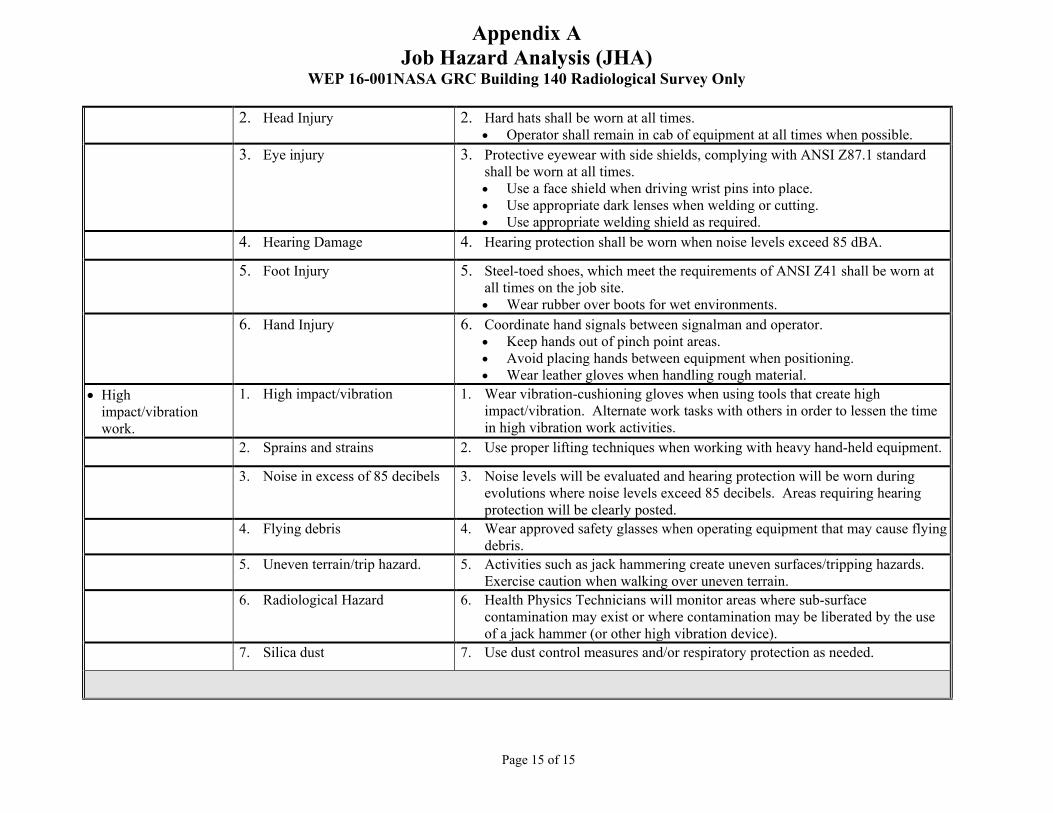
Appendix A Job Hazard Analysis (JHA)
WEP 16-001NASA GRC Building 140 Radiological Survey Only
Page 15 of 15
2. Head Injury 2. Hard hats shall be worn at all times. • Operator shall remain in cab of equipment at all times when possible.
3. Eye injury 3. Protective eyewear with side shields, complying with ANSI Z87.1 standard shall be worn at all times. • Use a face shield when driving wrist pins into place. • Use appropriate dark lenses when welding or cutting. • Use appropriate welding shield as required.
4. Hearing Damage 4. Hearing protection shall be worn when noise levels exceed 85 dBA.
5. Foot Injury 5. Steel-toed shoes, which meet the requirements of ANSI Z41 shall be worn at all times on the job site. • Wear rubber over boots for wet environments.
6. Hand Injury 6. Coordinate hand signals between signalman and operator. • Keep hands out of pinch point areas. • Avoid placing hands between equipment when positioning. • Wear leather gloves when handling rough material.
• High impact/vibration work.
1. High impact/vibration 1. Wear vibration-cushioning gloves when using tools that create high impact/vibration. Alternate work tasks with others in order to lessen the time in high vibration work activities.
2. Sprains and strains 2. Use proper lifting techniques when working with heavy hand-held equipment.
3. Noise in excess of 85 decibels 3. Noise levels will be evaluated and hearing protection will be worn during evolutions where noise levels exceed 85 decibels. Areas requiring hearing protection will be clearly posted.
4. Flying debris 4. Wear approved safety glasses when operating equipment that may cause flying debris.
5. Uneven terrain/trip hazard. 5. Activities such as jack hammering create uneven surfaces/tripping hazards. Exercise caution when walking over uneven terrain.
6. Radiological Hazard 6. Health Physics Technicians will monitor areas where sub-surface contamination may exist or where contamination may be liberated by the use of a jack hammer (or other high vibration device).
7. Silica dust 7. Use dust control measures and/or respiratory protection as needed.

Appendix B Dose Model Reports
Work Execution Package Number: WEP-16-002 Revision No. 0
WEP-16-002 NASA GRC Building 140 Radiological Survey Only
Dose Model Reports
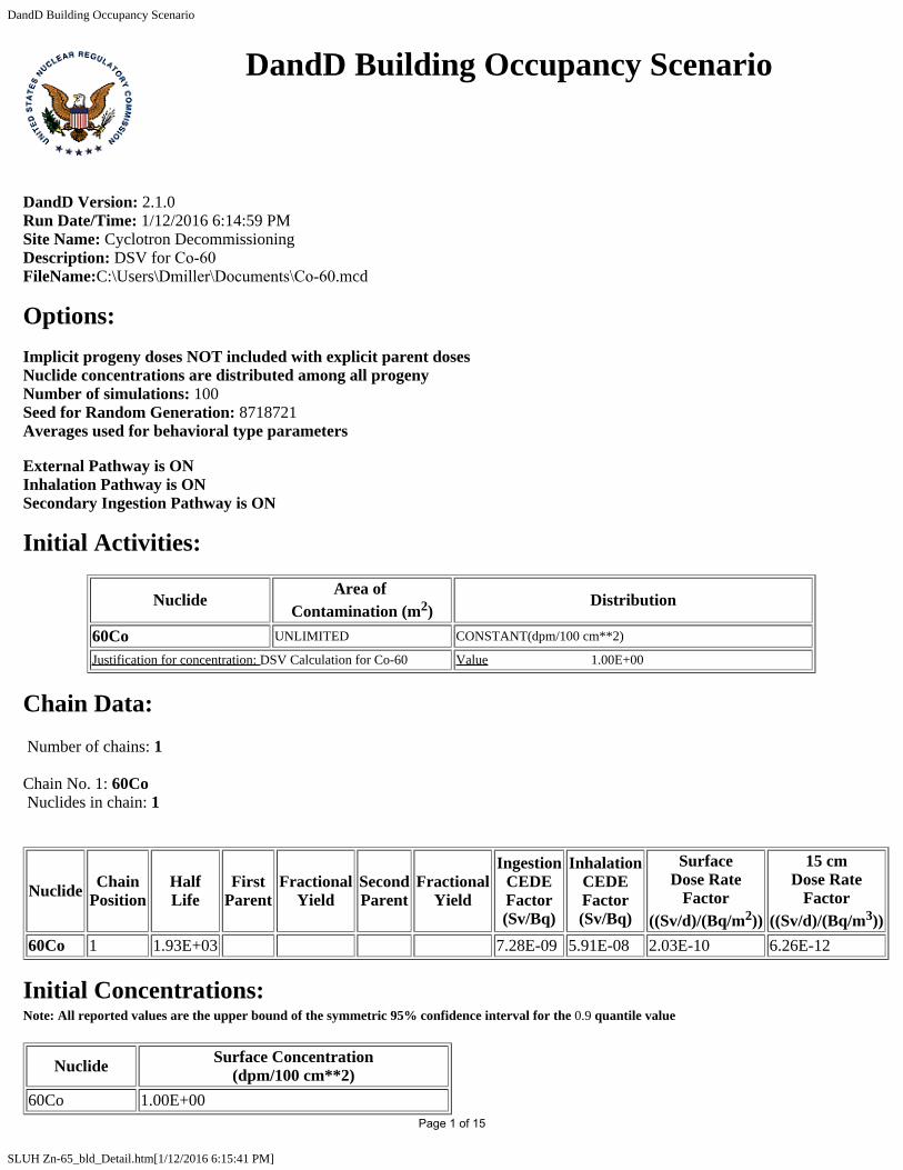
DandD Building Occupancy Scenario
SLUH Zn-65_bld_Detail.htm[1/12/2016 6:15:41 PM]
DandD Building Occupancy Scenario
DandD Version: 2.1.0 Run Date/Time: 1/12/2016 6:14:59 PMSite Name: Cyclotron Decommissioning Description: DSV for Co-60 FileName:C:\Users\Dmiller\Documents\Co-60.mcd
Options:Implicit progeny doses NOT included with explicit parent doses Nuclide concentrations are distributed among all progeny Number of simulations: 100 Seed for Random Generation: 8718721 Averages used for behavioral type parameters
External Pathway is ON Inhalation Pathway is ON Secondary Ingestion Pathway is ON
Initial Activities:
NuclideArea of
Contamination (m2)Distribution
60Co UNLIMITED CONSTANT(dpm/100 cm**2)
Justification for concentration: DSV Calculation for Co-60 Value 1.00E+00
Chain Data: Number of chains: 1
Chain No. 1: 60Co Nuclides in chain: 1
Nuclide ChainPosition
HalfLife
FirstParent
FractionalYield
SecondParent
FractionalYield
IngestionCEDEFactor(Sv/Bq)
InhalationCEDEFactor(Sv/Bq)
SurfaceDose Rate
Factor((Sv/d)/(Bq/m2))
15 cmDose Rate
Factor((Sv/d)/(Bq/m3))
60Co 1 1.93E+03 7.28E-09 5.91E-08 2.03E-10 6.26E-12
Initial Concentrations:Note: All reported values are the upper bound of the symmetric 95% confidence interval for the 0.9 quantile value
Nuclide Surface Concentration(dpm/100 cm**2)
60Co 1.00E+00Page 1 of 15

DandD Building Occupancy Scenario
SLUH Zn-65_bld_Detail.htm[1/12/2016 6:15:41 PM]
Model Parameters:
General Parameters:
Parameter Name Description Distribution
To:Time In Building The time in the building during the occupancy period CONSTANT(hr/week)
Default value used Value 4.50E+01
Tto:Occupancy Period The duration of the occupancy exposure period CONSTANT(days)
Default value used Value 3.65E+02
Vo:Breathing Rate The average volumetric breathing rate during building occupancy for an 8-hour work day CONSTANT(m**3/hr)
Default value used Value 1.40E+00
RFo*:Resuspension Factor
Effective resuspension factor during the occupancy period = RFo * Fl DERIVED(1/m)
Default value used
GO*:Ingestion RateEffective secondary ingestion transfer rate of removable surface activity from building surfaces to the mouth during building occupancy = GO * Fl
DERIVED(m**2/hr)
Default value used
Tstart:Start Time The start time of the scenario in days CONSTANT(days)
Default value used Value 0.00E+00
Tend:End Time The ending time of the scenario in days CONSTANT(days)
Default value used Value 3.65E+02
dt:Time Step Size The time step size CONSTANT(days)
Default value used Value 3.65E+02
Pstep:Print Step SizeThe time steps for the history file. Doses will be written to the history file every n time steps
CONSTANT(none)
Default value used Value 1.00E+00
AOExt:External Exposure Area
Minimum surface area to which occupant is exposed via external radiation during occupancy period
CONSTANT(m**2)
Default value used Value 1.00E+01
AOInh:Inhalation Exposure Area
Minimum surface area to which occupant is exposed via inhalation during occupancy period
CONSTANT(m**2)
Default value used Value 1.00E+01
AOIng:Secondary Ingestion Exposure Area
Minimum surface area to which occupant is exposed via secondary ingestion during occupancy period
CONSTANT(m**2)
Default value used Value 1.00E+01
AO:Exposure Area Minimum surface area to which occupant is exposed during the occupancy period DERIVED(m**2)
Default value used
Fl:Loose Fraction Fraction of surface contamination available for resuspension and ingestion CONSTANT(none)
Page 2 of 15

DandD Building Occupancy Scenario
SLUH Zn-65_bld_Detail.htm[1/12/2016 6:15:41 PM]
Default value used Value 1.00E-01
Rfo:Loose Resuspension Factor Resuspension factor for loose contamination CONTINUOUS LOGARITHMIC(1/m)
Default value used Value Probability9.12E-06 0.00E+001.10E-04 7.67E-011.46E-04 9.09E-011.62E-04 9.50E-011.85E-04 9.90E-011.90E-04 1.00E+00
GO:Loose Ingestion Rate
The secondary ingestion transfer rate of loose removable surface activity from building surfaces to the mouth during building occupancy
CONSTANT(m**2/hr)
Default value used Value 1.10E-04
Correlation Coefficients:
None
Summary Results:90.00% of the 100 calculated TEDE values are < 3.55E-03 mrem/year .The 95 % Confidence Interval for the 0.9 quantile value of TEDE is 3.50E-03 to 3.61E-03 mrem/year
Detailed Results:Note: All reported values are the upper bound of the symmetric 95% confidence interval for the 0.9 quantile value
Concentration at Time of Peak Dose:
Nuclide Surface Concentration(dpm/100 cm**2)
60Co 9.37E-01
Pathway Dose from All Nuclides (mrem)
All PathwaysDose External Inhalation Secondary
Ingestion3.61E-03 3.09E-03 4.87E-04 2.93E-05
Radionuclide Dose through All Active Pathways (mrem)
Nuclide All PathwaysDose
60Co 3.61E-03All Nuclides 3.61E-03
Dose from Each Nuclide through Each Active Pathway (mrem)
Nuclide External Inhalation SecondaryIngestion
Page 3 of 15

DandD Building Occupancy Scenario
SLUH Zn-65_bld_Detail.htm[1/12/2016 6:15:41 PM]
60Co 3.09E-03 4.87E-04 2.93E-05
Page 4 of 15

DandD Building Occupancy Scenario
SLUH Zn-65_bld_Detail.htm[1/12/2016 6:19:09 PM]
DandD Building Occupancy Scenario
DandD Version: 2.1.0 Run Date/Time: 1/12/2016 6:18:53 PMSite Name: Cyclotron Decommissioning Description: DSV for Eu-152 FileName:C:\Users\Dmiller\Documents\Eu-152.mcd
Options:Implicit progeny doses NOT included with explicit parent doses Nuclide concentrations are distributed among all progeny Number of simulations: 100 Seed for Random Generation: 8718721 Averages used for behavioral type parameters
External Pathway is ON Inhalation Pathway is ON Secondary Ingestion Pathway is ON
Initial Activities:
NuclideArea of
Contamination (m2)Distribution
152Eu UNLIMITED CONSTANT(dpm/100 cm**2)
Justification for concentration: DSV Calculation E-152 Value 1.00E+00
Chain Data: Number of chains: 1
Chain No. 1: 152Eu Nuclides in chain: 2
Nuclide ChainPosition
HalfLife
FirstParent
FractionalYield
SecondParent
FractionalYield
IngestionCEDEFactor(Sv/Bq)
InhalationCEDEFactor(Sv/Bq)
SurfaceDose Rate
Factor((Sv/d)/(Bq/m2))
15 cmDose Rate
Factor((Sv/d)/(Bq/m3))
152Eu 1 4.87E+03 1.75E-09 5.97E-08 9.53E-11 2.78E-12152Gd 2 3.94E+16 1 0.2792 4.34E-08 1.01E-06 0.00E+00 0.00E+00
Initial Concentrations:Note: All reported values are the upper bound of the symmetric 95% confidence interval for the 0.9 quantile value
Nuclide Surface Concentration(dpm/100 cm**2)
Page 5 of 15

DandD Building Occupancy Scenario
SLUH Zn-65_bld_Detail.htm[1/12/2016 6:19:09 PM]
152Eu 1.00E+00152Gd 0.00E+00
Model Parameters:
General Parameters:
Parameter Name Description Distribution
To:Time In Building The time in the building during the occupancy period CONSTANT(hr/week)
Default value used Value 4.50E+01
Tto:Occupancy Period The duration of the occupancy exposure period CONSTANT(days)
Default value used Value 3.65E+02
Vo:Breathing Rate The average volumetric breathing rate during building occupancy for an 8-hour work day CONSTANT(m**3/hr)
Default value used Value 1.40E+00
RFo*:Resuspension Factor
Effective resuspension factor during the occupancy period = RFo * Fl DERIVED(1/m)
Default value used
GO*:Ingestion RateEffective secondary ingestion transfer rate of removable surface activity from building surfaces to the mouth during building occupancy = GO * Fl
DERIVED(m**2/hr)
Default value used
Tstart:Start Time The start time of the scenario in days CONSTANT(days)
Default value used Value 0.00E+00
Tend:End Time The ending time of the scenario in days CONSTANT(days)
Default value used Value 3.65E+02
dt:Time Step Size The time step size CONSTANT(days)
Default value used Value 3.65E+02
Pstep:Print Step SizeThe time steps for the history file. Doses will be written to the history file every n time steps
CONSTANT(none)
Default value used Value 1.00E+00
AOExt:External Exposure Area
Minimum surface area to which occupant is exposed via external radiation during occupancy period
CONSTANT(m**2)
Default value used Value 1.00E+01
AOInh:Inhalation Exposure Area
Minimum surface area to which occupant is exposed via inhalation during occupancy period
CONSTANT(m**2)
Default value used Value 1.00E+01
AOIng:Secondary Ingestion Exposure Area
Minimum surface area to which occupant is exposed via secondary ingestion during occupancy period
CONSTANT(m**2)
Default value used Value 1.00E+01
AO:Exposure Area Minimum surface area to which occupant is exposed during the occupancy period DERIVED(m**2)
Page 6 of 15

DandD Building Occupancy Scenario
SLUH Zn-65_bld_Detail.htm[1/12/2016 6:19:09 PM]
Default value used
Fl:Loose Fraction Fraction of surface contamination available for resuspension and ingestion CONSTANT(none)
Default value used Value 1.00E-01
Rfo:Loose Resuspension Factor Resuspension factor for loose contamination CONTINUOUS LOGARITHMIC(1/m)
Default value used Value Probability9.12E-06 0.00E+001.10E-04 7.67E-011.46E-04 9.09E-011.62E-04 9.50E-011.85E-04 9.90E-011.90E-04 1.00E+00
GO:Loose Ingestion Rate
The secondary ingestion transfer rate of loose removable surface activity from building surfaces to the mouth during building occupancy
CONSTANT(m**2/hr)
Default value used Value 1.10E-04
Correlation Coefficients:
None
Summary Results:90.00% of the 100 calculated TEDE values are < 1.97E-03 mrem/year .The 95 % Confidence Interval for the 0.9 quantile value of TEDE is 1.92E-03 to 2.03E-03 mrem/year
Detailed Results:Note: All reported values are the upper bound of the symmetric 95% confidence interval for the 0.9 quantile value
Concentration at Time of Peak Dose:
Nuclide Surface Concentration(dpm/100 cm**2)
152Eu 9.74E-01152Gd 8.82E-16
Pathway Dose from All Nuclides (mrem)
All PathwaysDose External Inhalation Secondary
Ingestion2.03E-03 1.51E-03 5.12E-04 7.32E-06
Radionuclide Dose through All Active Pathways (mrem)
Nuclide All PathwaysDose
152Eu 2.03E-03152Gd 8.00E-18All Nuclides 2.03E-03
Page 7 of 15

DandD Building Occupancy Scenario
SLUH Zn-65_bld_Detail.htm[1/12/2016 6:19:09 PM]
Dose from Each Nuclide through Each Active Pathway (mrem)
Nuclide External Inhalation SecondaryIngestion
152Eu 1.51E-03 5.12E-04 7.32E-06152Gd 0.00E+00 7.84E-18 1.64E-19
Page 8 of 15
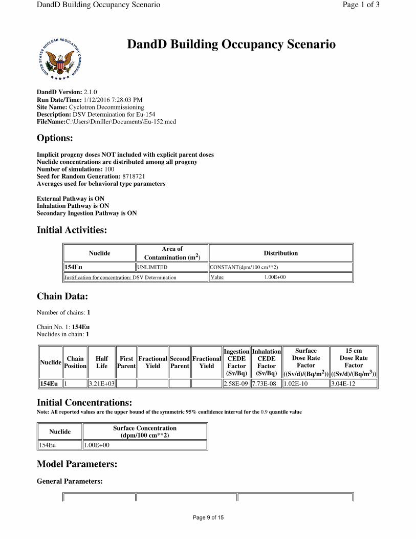
DandD Building Occupancy Scenario
DandD Version: 2.1.0
Run Date/Time: 1/12/2016 7:28:03 PMSite Name: Cyclotron DecommissioningDescription: DSV Determination for Eu-154FileName:C:\Users\Dmiller\Documents\Eu-152.mcd
Options:
Implicit progeny doses NOT included with explicit parent doses Nuclide concentrations are distributed among all progeny Number of simulations: 100 Seed for Random Generation: 8718721 Averages used for behavioral type parameters
External Pathway is ON Inhalation Pathway is ON Secondary Ingestion Pathway is ON
Initial Activities:
Chain Data:
Number of chains: 1
Chain No. 1: 154Eu Nuclides in chain: 1
Initial Concentrations:Note: All reported values are the upper bound of the symmetric 95% confidence interval for the 0.9 quantile value
Model Parameters:
General Parameters:
NuclideArea of
Contamination (m2)Distribution
154Eu UNLIMITED CONSTANT(dpm/100 cm**2)
Justification for concentration: DSV Determination Value 1.00E+00
NuclideChain
PositionHalf Life
First Parent
Fractional Yield
Second Parent
Fractional Yield
Ingestion CEDE Factor (Sv/Bq)
Inhalation CEDE Factor (Sv/Bq)
Surface Dose Rate
Factor
((Sv/d)/(Bq/m2))
15 cm Dose Rate
Factor
((Sv/d)/(Bq/m3))
154Eu 1 3.21E+03 2.58E-09 7.73E-08 1.02E-10 3.04E-12
NuclideSurface Concentration
(dpm/100 cm**2)
154Eu 1.00E+00
Page 1 of 3DandD Building Occupancy Scenario
Page 9 of 15

Parameter Name Description Distribution
To:Time In BuildingThe time in the building during the occupancy period
CONSTANT(hr/week)
Default value used Value 4.50E+01
Tto:Occupancy PeriodThe duration of the occupancy exposure period
CONSTANT(days)
Default value used Value 3.65E+02
Vo:Breathing RateThe average volumetric breathing rate during building occupancy for an 8-hour work day
CONSTANT(m**3/hr)
Default value used Value 1.40E+00
RFo*:Resuspension Factor
Effective resuspension factor during the occupancy period = RFo * Fl
DERIVED(1/m)
Default value used
GO*:Ingestion Rate
Effective secondary ingestion transfer rate of removable surface activity from building surfaces to the mouth during building occupancy = GO * Fl
DERIVED(m**2/hr)
Default value used
Tstart:Start Time The start time of the scenario in days CONSTANT(days)
Default value used Value 0.00E+00
Tend:End Time The ending time of the scenario in days CONSTANT(days)
Default value used Value 3.65E+02
dt:Time Step Size The time step size CONSTANT(days)
Default value used Value 3.65E+02
Pstep:Print Step SizeThe time steps for the history file. Doses will be written to the history file every n time steps
CONSTANT(none)
Default value used Value 1.00E+00
AOExt:External Exposure Area
Minimum surface area to which occupant is exposed via external radiation during occupancy period
CONSTANT(m**2)
Default value used Value 1.00E+01
AOInh:Inhalation Exposure Area
Minimum surface area to which occupant is exposed via inhalation during occupancy period
CONSTANT(m**2)
Default value used Value 1.00E+01
AOIng:Secondary Ingestion Exposure Area
Minimum surface area to which occupant is exposed via secondary ingestion during occupancy period
CONSTANT(m**2)
Default value used Value 1.00E+01
AO:Exposure AreaMinimum surface area to which occupant is exposed during the occupancy period
DERIVED(m**2)
Default value used
Fl:Loose FractionFraction of surface contamination available for resuspension and ingestion
CONSTANT(none)
Default value used Value 1.00E-01
Rfo:Loose Resuspension Factor
Resuspension factor for loose contamination CONTINUOUS LOGARITHMIC(1/m)
Default value used Value Probability
9.12E-06 0.00E+00
1.10E-04 7.67E-01
1.46E-04 9.09E-01
1.62E-04 9.50E-01
1.85E-04 9.90E-01
1.90E-04 1.00E+00
GO:Loose Ingestion The secondary ingestion transfer rate of loose removable surface activity from
Page 2 of 3DandD Building Occupancy Scenario
Page 10 of 15

Correlation Coefficients:
None
Summary Results:
90.00% of the 100 calculated TEDE values are < 2.18E-03 mrem/year . The 95 % Confidence Interval for the 0.9 quantile value of TEDE is 2.12E-03 to 2.26E-03 mrem/year
Detailed Results:Note: All reported values are the upper bound of the symmetric 95% confidence interval for the 0.9 quantile value
Concentration at Time of Peak Dose:
Pathway Dose from All Nuclides (mrem)
Radionuclide Dose through All Active Pathways (mrem)
Dose from Each Nuclide through Each Active Pathway (mrem)
Rate building surfaces to the mouth during building occupancy
CONSTANT(m**2/hr)
Default value used Value 1.10E-04
NuclideSurface Concentration
(dpm/100 cm**2)
154Eu 9.62E-01
All Pathways Dose
External InhalationSecondary Ingestion
2.26E-03 1.59E-03 6.54E-04 1.06E-05
NuclideAll Pathways
Dose
154Eu 2.26E-03
All Nuclides 2.26E-03
Nuclide External InhalationSecondary Ingestion
154Eu 1.59E-03 6.54E-04 1.06E-05
Page 3 of 3DandD Building Occupancy Scenario
Page 11 of 15

DandD Building Occupancy Scenario
SLUH Zn-65_bld_Detail.htm[1/12/2016 5:32:19 PM]
DandD Building Occupancy Scenario
DandD Version: 2.1.0 Run Date/Time: 1/12/2016 5:29:47 PMSite Name: Cyclotron Decommissioning Description: DSV for Na-22 FileName:C:\Users\Dmiller\Documents\Na-22.mcd
Options:Implicit progeny doses NOT included with explicit parent doses Nuclide concentrations are distributed among all progeny Number of simulations: 100 Seed for Random Generation: 8718721 Averages used for behavioral type parameters
External Pathway is ON Inhalation Pathway is ON Secondary Ingestion Pathway is ON
Initial Activities:
NuclideArea of
Contamination (m2)Distribution
22Na UNLIMITED CONSTANT(dpm/100 cm**2)
Justification for concentration: DSV Calculation Value 1.00E+00
Chain Data: Number of chains: 1
Chain No. 1: 22Na Nuclides in chain: 1
Nuclide ChainPosition
HalfLife
FirstParent
FractionalYield
SecondParent
FractionalYield
IngestionCEDEFactor(Sv/Bq)
InhalationCEDEFactor(Sv/Bq)
SurfaceDose Rate
Factor((Sv/d)/(Bq/m2))
15 cmDose Rate
Factor((Sv/d)/(Bq/m3))
22Na 1 9.50E+02 3.10E-09 2.07E-09 1.82E-10 5.45E-12
Initial Concentrations:Note: All reported values are the upper bound of the symmetric 95% confidence interval for the 0.9 quantile value
Nuclide Surface Concentration(dpm/100 cm**2)
22Na 1.00E+00Page 12 of 15

DandD Building Occupancy Scenario
SLUH Zn-65_bld_Detail.htm[1/12/2016 5:32:19 PM]
Model Parameters:
General Parameters:
Parameter Name Description Distribution
To:Time In Building The time in the building during the occupancy period CONSTANT(hr/week)
Default value used Value 4.50E+01
Tto:Occupancy Period The duration of the occupancy exposure period CONSTANT(days)
Default value used Value 3.65E+02
Vo:Breathing Rate The average volumetric breathing rate during building occupancy for an 8-hour work day CONSTANT(m**3/hr)
Default value used Value 1.40E+00
RFo*:Resuspension Factor
Effective resuspension factor during the occupancy period = RFo * Fl DERIVED(1/m)
Default value used
GO*:Ingestion RateEffective secondary ingestion transfer rate of removable surface activity from building surfaces to the mouth during building occupancy = GO * Fl
DERIVED(m**2/hr)
Default value used
Tstart:Start Time The start time of the scenario in days CONSTANT(days)
Default value used Value 0.00E+00
Tend:End Time The ending time of the scenario in days CONSTANT(days)
Default value used Value 3.65E+02
dt:Time Step Size The time step size CONSTANT(days)
Default value used Value 3.65E+02
Pstep:Print Step SizeThe time steps for the history file. Doses will be written to the history file every n time steps
CONSTANT(none)
Default value used Value 1.00E+00
AOExt:External Exposure Area
Minimum surface area to which occupant is exposed via external radiation during occupancy period
CONSTANT(m**2)
Default value used Value 1.00E+01
AOInh:Inhalation Exposure Area
Minimum surface area to which occupant is exposed via inhalation during occupancy period
CONSTANT(m**2)
Default value used Value 1.00E+01
AOIng:Secondary Ingestion Exposure Area
Minimum surface area to which occupant is exposed via secondary ingestion during occupancy period
CONSTANT(m**2)
Default value used Value 1.00E+01
AO:Exposure Area Minimum surface area to which occupant is exposed during the occupancy period DERIVED(m**2)
Default value used
Fl:Loose Fraction Fraction of surface contamination available for resuspension and ingestion CONSTANT(none)
Page 13 of 15

DandD Building Occupancy Scenario
SLUH Zn-65_bld_Detail.htm[1/12/2016 5:32:19 PM]
Default value used Value 1.00E-01
Rfo:Loose Resuspension Factor Resuspension factor for loose contamination CONTINUOUS LOGARITHMIC(1/m)
Default value used Value Probability9.12E-06 0.00E+001.10E-04 7.67E-011.46E-04 9.09E-011.62E-04 9.50E-011.85E-04 9.90E-011.90E-04 1.00E+00
GO:Loose Ingestion Rate
The secondary ingestion transfer rate of loose removable surface activity from building surfaces to the mouth during building occupancy
CONSTANT(m**2/hr)
Default value used Value 1.10E-04
Correlation Coefficients:
None
Summary Results:90.00% of the 100 calculated TEDE values are < 2.62E-03 mrem/year .The 95 % Confidence Interval for the 0.9 quantile value of TEDE is 2.62E-03 to 2.62E-03 mrem/year
Detailed Results:Note: All reported values are the upper bound of the symmetric 95% confidence interval for the 0.9 quantile value
Concentration at Time of Peak Dose:
Nuclide Surface Concentration(dpm/100 cm**2)
22Na 8.78E-01
Pathway Dose from All Nuclides (mrem)
All PathwaysDose External Inhalation Secondary
Ingestion2.62E-03 2.60E-03 1.60E-05 1.17E-05
Radionuclide Dose through All Active Pathways (mrem)
Nuclide All PathwaysDose
22Na 2.62E-03All Nuclides 2.62E-03
Dose from Each Nuclide through Each Active Pathway (mrem)
Nuclide External Inhalation SecondaryIngestion
Page 14 of 15

DandD Building Occupancy Scenario
SLUH Zn-65_bld_Detail.htm[1/12/2016 5:32:19 PM]
22Na 2.60E-03 1.60E-05 1.17E-05
Page 15 of 15

Attachment A Fall Prevention Plan
Work Execution Package Number: WEP-16-002 Revisio n No. 1
WEP-16-002 NASA GRC Building 140 Radiological Survey Only
Fall Prevention Plan
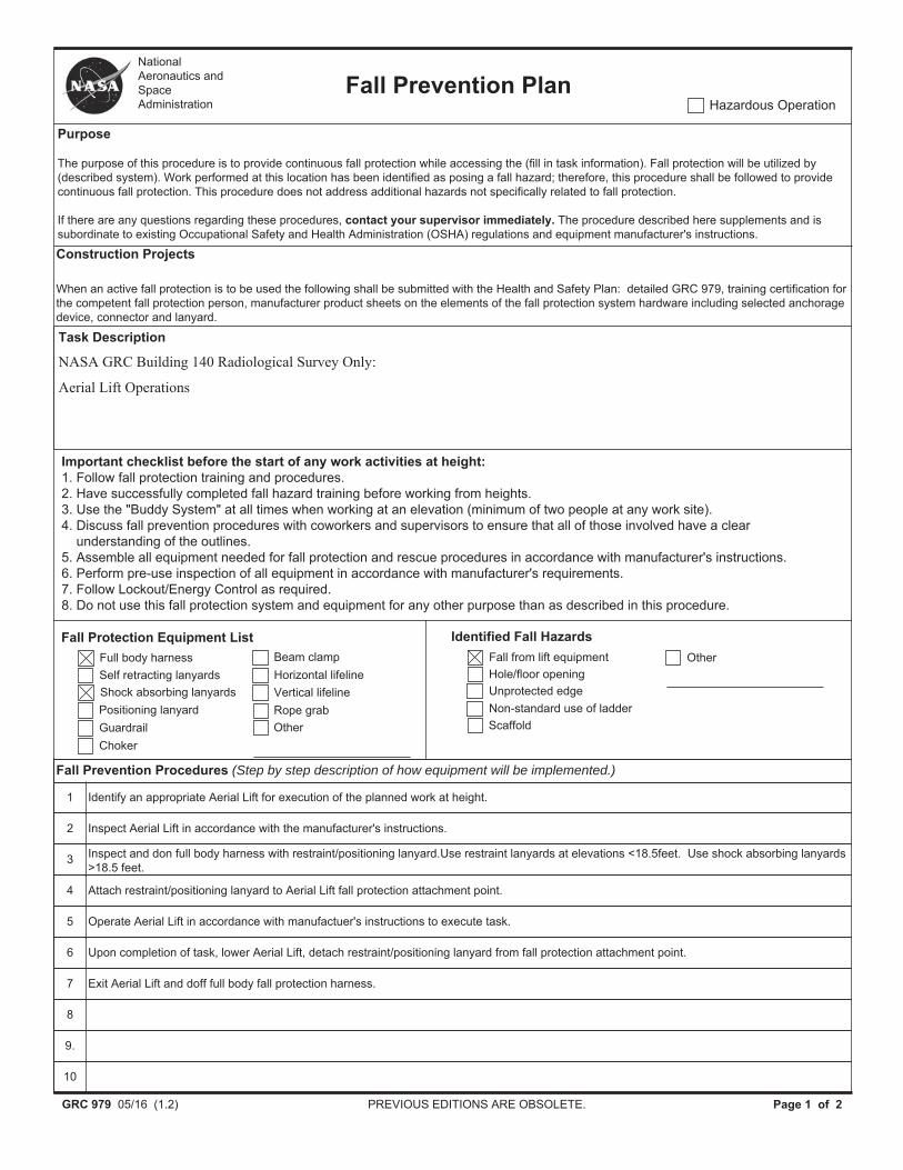
GRC 979 05/16 (1.2) PREVIOUS EDITIONS ARE OBSOLETE. Page 1 of 2
Fall Prevention Plan
Purpose
The purpose of this procedure is to provide continuous fall protection while accessing the (fill in task information). Fall protection will be utilized by (described system). Work performed at this location has been identified as posing a fall hazard; therefore, this procedure shall be followed to provide continuous fall protection. This procedure does not address additional hazards not specifically related to fall protection.
If there are any questions regarding these procedures, contact your supervisor immediately. The procedure described here supplements and is subordinate to existing Occupational Safety and Health Administration (OSHA) regulations and equipment manufacturer's instructions.
Task Description
NASA GRC Building 140 Radiological Survey Only:
Aerial Lift Operations
National Aeronautics and Space Administration Hazardous Operation
Important checklist before the start of any work activities at height: 1. Follow fall protection training and procedures.2. Have successfully completed fall hazard training before working from heights.3. Use the "Buddy System" at all times when working at an elevation (minimum of two people at any work site).4. Discuss fall prevention procedures with coworkers and supervisors to ensure that all of those involved have a clear
understanding of the outlines.5. Assemble all equipment needed for fall protection and rescue procedures in accordance with manufacturer's instructions.6. Perform pre-use inspection of all equipment in accordance with manufacturer's requirements.7. Follow Lockout/Energy Control as required.8. Do not use this fall protection system and equipment for any other purpose than as described in this procedure.
Fall Protection Equipment ListFull body harnessSelf retracting lanyardsShock absorbing lanyardsPositioning lanyardGuardrailChoker
Beam clampHorizontal lifelineVertical lifelineRope grabOther
Fall from lift equipmentIdentified Fall Hazards
Hole/floor openingUnprotected edgeNon-standard use of ladderScaffold
Other
Fall Prevention Procedures (Step by step description of how equipment will be implemented.)
1 Identify an appropriate Aerial Lift for execution of the planned work at height.
2 Inspect Aerial Lift in accordance with the manufacturer's instructions.
3 Inspect and don full body harness with restraint/positioning lanyard.Use restraint lanyards at elevations <18.5feet. Use shock absorbing lanyards >18.5 feet.
4 Attach restraint/positioning lanyard to Aerial Lift fall protection attachment point.
5 Operate Aerial Lift in accordance with manufactuer's instructions to execute task.
6 Upon completion of task, lower Aerial Lift, detach restraint/positioning lanyard from fall protection attachment point.
7 Exit Aerial Lift and doff full body fall protection harness.
8
9.
10
Construction Projects
When an active fall protection is to be used the following shall be submitted with the Health and Safety Plan: detailed GRC 979, training certification for the competent fall protection person, manufacturer product sheets on the elements of the fall protection system hardware including selected anchorage device, connector and lanyard.

GRC 979 05/16 (1.2) PREVIOUS EDITIONS ARE OBSOLETE. Page 2 of 2
Rescue Information
Normal first aid procedures should be performed by certified individuals as the situation requires.
Glenn Research Center Emergency Phone Numbers: Dial 911 on any NASA phone or 216-433-8888 on a cell phone.
Plum Brook Station Emergency Phone Numbers: Dial 911 on any NASA phone or 419-621-3222 on a cell phone.
Fall Prevention Plan
Phone Locations
Bldg 140 Skylight Room
First Aid Kit Locations (If other, please list.)
Bldg 49 Room 3, Radiation Safety Office
AED Locations
Bldg 49 First Floor Lobby
Rescue Plan (Step by step description of how equipment will be implemented.)
1. Buddy system or phone/radio communication
2. Spotter to assure safe peration
3. Rescue can be accomplished by spotter by lowering Aerial Lift.
Rescue Considerations
When personal fall arrest systems are used, the job site supervisor or designated competent person must assure that employees can be promptly rescued or can rescue themselves should a fall occur. The availability of rescue personnel, ladders, or other rescue equipment should be verified before work begins. In some situations, equipment that allows employees to rescue themselves after the fall has been arrested may be desirable, such as devices which have descent capability.
Sign off
All employees authorized to apply the procedures and use the equipment specified in this Fall Protection Plan will be given by a competent person the opportunity to review this plan and instructions on the proper use of the specific fall protection devices they will be using. Every employee permitted to work under this plan must sign below to verify they have been provided this opportunity and instructions.
*A COPY OF THIS WORK PLAN SHOULD BE AVAILABLE ON THE JOBSITE WHILE WORK IS BEING PERFORMED.
Competent Person Date

Addendum 1 Daily Activities
Work Execution Package Number: WEP-16-002 Revision No. 0
WEP-16-002 NASA GRC Building 140 Radiological Survey Only
Execution Package Daily Activities Plan

Addendum 1 Daily Activities
Work Execution Package Number: WEP-16-002 Revision No. 0
Page 1 of 3
ADDENDUM 1 DAILY ACTIVITY PLAN
Date: Reference Permits
WEP and Rev. # RWP #
WEP Name Confined Space Permit #
Building # Hot Work Permit #
Area/Location Critical Lift Plan #
Field Supervisor Excavations (Dig) #
Other
Safety Topic:
Planned Activities:
Safety Notes/Instructions:
Daily Check List Reviewed Yes N/A Initials Daily Hazards (Check all that apply.)
Job Hazard Analysis Vision Hazardous Energy Fire Work Instructions Noise Hand Access
Referenced Permits Head Slip, Trip, Fall Electrical RWP and Postings Foot Material Handling Communication
Implementing Procedures Face Thermal Ergonomic Other (specify) Respiratory Confined Space Interface
Lead Rescue Radiological Asbestos Chemical Exposure Other
Review the current radiological surveys associated with the RWP’s for this job and assure that the radiological conditions are discussed in the pre-job brief.

Addendum 1 Daily Activities
Work Execution Package Number: WEP-16-002 Revision No. 0
Page 2 of 3
DAILY ACTIVITY REPORT
WEP # Date
WEP Name:
Work Completed This Shift
Addendum 1 Daily Activities
Work Execution Package Number: WEP-16-002 Revision No. 0
Page 3 of 3
WEP Pre-Job Briefing Attendance Sheet
Please Circle: Initial or Daily
WEP NUMBER: Rev. # Conducted By:
WEP/WEP SUPPLEMENT NAME:
PRINT NAME SIGNATURE I.D. NUMBER DATE