Embed Size (px)
Citation preview
8/2/2019 Nasa Report on Gas Core Nuclear Engines
http://slidepdf.com/reader/full/nasa-report-on-gas-core-nuclear-engines 1/105
O N T R A C T O R
R E P O R T
LOAN COPY: RETURN TO
KlRTLANB AFB, N MEXAFWL (WLlL-2)
OF SPECIFIC NUCLEAR
GHT BULB A N D OPEN-CYCLE
GASEOUS
ROCKET ENGINES
G. H . McLdfferty und H , E. Bmer
by
Hartford, Conn.
AIRCRAFT CORPORATION
r
E R O N A U T IC SN D S PA CE A D M IN IS T R A T IO N W A S H IN G T O N , D. C . APRIL 1968
8/2/2019 Nasa Report on Gas Core Nuclear Engines
http://slidepdf.com/reader/full/nasa-report-on-gas-core-nuclear-engines 2/105
" . -
TECH LIBRARY KAFB, NM
' OObO4ObNASA CK- UYU
STUDIES OF SPECIFIC NUCLEAR LIGHT BULB AND OPEN -CYCLE
VORTEX-STABILIZED GASEOUS NUCLEAR ROCKET ENGINES
By G. H. McLafferty and H. E. Bauer
Distribution of th is re po rt is provided in the interest of
informationexchange.Respons ibility or hecontents
resides in the author or organizat ion that prep ared it.
Issued by Originator as Report No. F-910093-37
Prepa red uxlUr.-UNITED AIRCRAFT LtJ~n~NASw-847y
East Hartford, Conn. - -~-_
fo r
NATIONAL AERONAUTICS AND SPACE ADMINISTRATION
For sole b y t h e C l e a r i n g h o u s e f or F e d e r a l S c i e n t i f i c a n d T e c h n i c a l n f o r m a t i o n
S p r i n g f i e l d ,V i r g i n i o 22151 - CFSTl p r i c e $3.00

8/2/2019 Nasa Report on Gas Core Nuclear Engines
http://slidepdf.com/reader/full/nasa-report-on-gas-core-nuclear-engines 3/105
8/2/2019 Nasa Report on Gas Core Nuclear Engines
http://slidepdf.com/reader/full/nasa-report-on-gas-core-nuclear-engines 4/105
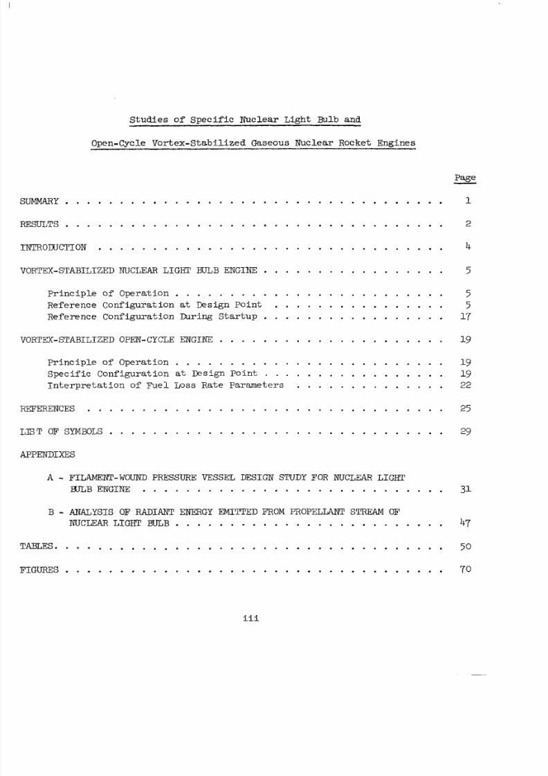
StudiesofSDeci f icNuclearLinht Eulb and
Open-Cycle Vortex-Stabilized Gaseous NuclearRocketEngines .age
. . . . . . . . . . . . . . . . . . . . . . . . . . . . . . . . . . . 1
. . . . . . . . . . . . . . . . . . . . . . . . . . . . . . . . . . . 2
. . . . . . . . . . . . . . . . . . . . . . . . . . . . . . . . 4
NUCLEAR LIGHT WTLB ENGINE . . . . . . . . . . . . . . . . . 5
Pr inc ip l efpera t ion . . . . . . . . . . . . . . . . . . . . . . . . . 5Referenceonfigurat ion a t Designoint . . . . . . . . . . . . . . . . 5ReferenceConfigurat ionDuring tartup . . . . . . . . . . . . . . . . . 17
OPEN-CYCLE ENGINE 19
P r i n c i p l e of Opera t ion . . . . . . . . . . . . . . . . . . . . . . . . . 19
I n t e r p r e t a t i o n fF u e l Loss Rate Parameters . . . . . . . . . . . . . . 22
Spec i f icConf igura t i on a t Design oint . . . . . . . . . . . . . . . . . 19
. . . . . . . . . . . . . . . . . . . . . . . . . . . . . . . . . 25
E T OF SYMBOLS. . . . . . . . . . . . . . . . . . . . . . . . . . . . . . . 29
A . ILAMENT-WOUNDPRESSURE VESSEL DESIGNSTUDYFOR NUCLEAR LIGHT
WTLB ENGINE . . . . . . . . . . . . . . . . . . . . . . . . . . . . 31
B . NALYSIS OF RADANT ENERGY EMITTED FROM PROPELIANT STREAM OF
NUCL;EAR LIGHT BULB . . . . . . . . . . . . . . . . . . . . . . . . . 47
. . . . . . . . . . . . . . . . . . . . . . . . . . . . . . . . . . . . 50
. . . . . . . . . . . . . . . . . . . . . . . . . . . . . . . . . . . 70
iii
.
8/2/2019 Nasa Report on Gas Core Nuclear Engines
http://slidepdf.com/reader/full/nasa-report-on-gas-core-nuclear-engines 5/105
S t u d i e s of Spec i f ic Nuc l ea rLig ht Eulb and
Open-Cycle Vortex-Stabilized Gaseous .~-uclear Rocket Engines
SUMMARY
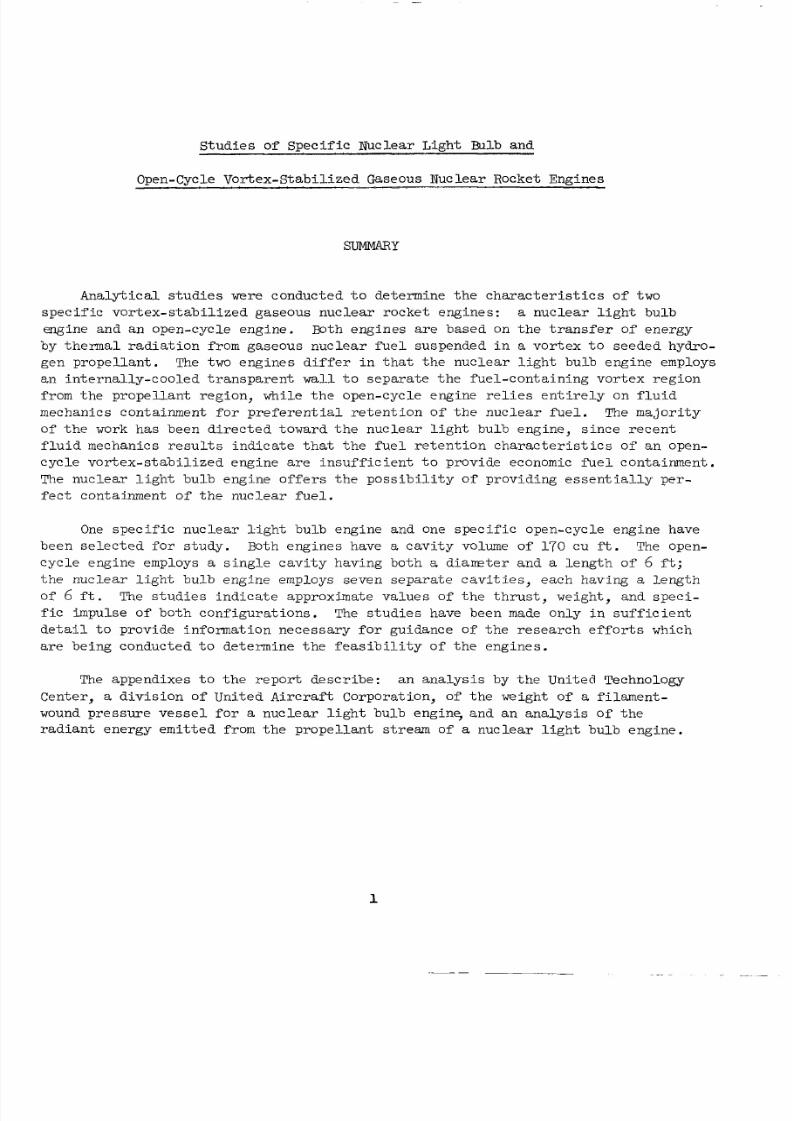
A n a l y t i c a l s t u d i e s were conducted t o determine t h e c h a r a c t e r i s t i c s o f two
spec i f i cvor t ex-s t ab i l i z edg a s e o u sn u c l e a r o c k e te n g i n e s : a n u c l e a r i g h tb u l b
engineandanopen-cycleengine. Both eng ines are b a s e d o n t h e r a n s f e r o f energy
by t he rma l r ad i a t i on f rom gaseous nuc l ea r fue l suspended i n a vor t ex t o s eeded hydro-
genpropel lant . The two e n g i n e sd i f f e r n h a t h en u c l e a r i g h tb u l bengine employs
an n t e rna l l y -coo l ed ranspa ren t wall to sepa ra t e he fue l -con t a in in g vor t ex reg ionfrom theprope l l an treg ion ,whi l e heopen-cyc l eeng ine r e l i e s e n t i r e l y o n f l u i d
m e c h a n i c sc o n t a i n m e n t o rp r e f e r e n t i a l e t e n t i o no f h enuc l ea r ue l . The ma jo r i t y
of he work ha s been d i rec t ed oward he nuc l ea r i gh t bu lb eng ine , s i nce recen t
f l u i d m ech an ics r e s u l t s i n d i c a t e t h a t t h e f u e l r e t e n t i o n c h a r a c t e r i s t i c s o f a n open-
c y c l evor t ex-s t ab i l i z ed e n g i n e are i ns uf f i c i e n t o p ro v id e economic fue l c o n t a i n m e n t .
The n u c l e a r i g h t b u l b e n g i n e o f f e r s h e p o s s i b i l i t y o f p r o v i d i n g e s s e n t i a l l y p e r -
f e c t c o n t a i n m e n to f h e n u c l e a r f u e l .
One specificn u c l e a r i g h tb u l be n g i n ean d one specificopen-cycleenginehave
been e lec te d or tudy . Both engines have a cavi ty volume of 170 cu ft. The open-
cyc leengine employs a s i n g l e c a v i t y h a v i n g b o t h a d i a m t e r a n d a l e n g t h o f 6 f t ;t h en u c l e a r i g h tb u l ben gin e employs seve nsepara tecavi t i es ,eachhav ing a l eng th
of 6 f t . The s tud ies nd ica tea p p r o x i m a t ev a l u e so f h e h r u s t ,w e i g h t ,a n dspec i -
f i c i m p u l s eofbothconf igura t ions . The s t ud ie s havebeen made on ly i n s u f f i c i e n t
d e t a i l o p r o v i d e n f o r m a t i o n n e c e s s a r y f o r g u i d a n c e of t h e r e s e a r c h e f f o r t s which
are beingc on d uc te d t o d e t e r m i n e t h e f e a s i b i l i t y o f t h e e n g i n e s .
The appendixes to he e po r t d e s c r i b e :a na n a l y s i s by t h e Uni ted Technology
Center, a d i v i s i o n of Uni tedAirc ra f tCorpora t ion,of heweight of a f i l ament -
wound pressure vesse l for a n u c l e a r l i g h t b u l b e n g i n e , a n d an a n a l y s i s o f t h e
rad i an t ene rgy emi t t ed from the p ro pe l l an t stream of a n u c l e a r i g h t b u l b e n g i n e .
1
8/2/2019 Nasa Report on Gas Core Nuclear Engines
http://slidepdf.com/reader/full/nasa-report-on-gas-core-nuclear-engines 6/105
RESULTS
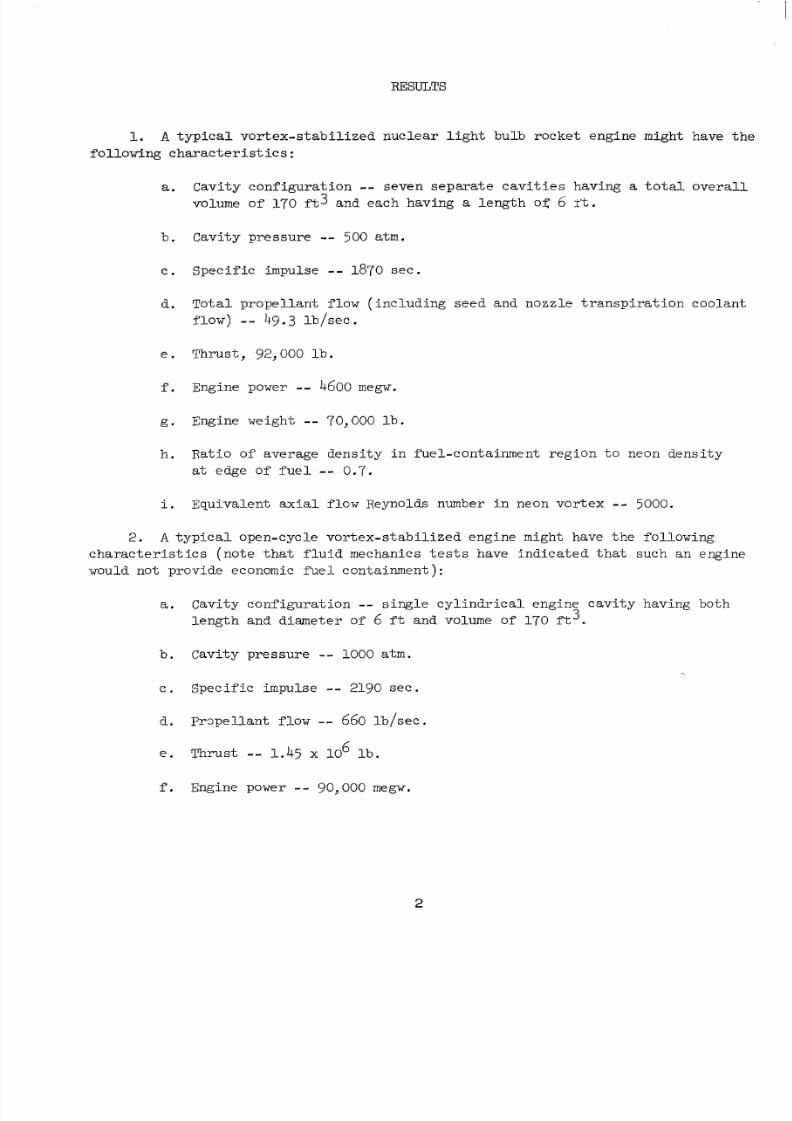
1. A t y p i c a lv o r t e x - s t a b i l i z e d n u c l e a r i g h tb u l b r o c k e t e n g i n e mig ht have th e
f o l l o w i n g c h a r a c t e r i s t i c s :
a. Cavi tyconf igura t ion -- seven sepaxa t ecav i t i e shav ing a t o t a l o v e r a l lvolume of 170 f t 3 andeachhaving a l eng th of 6 T ' t .
b .Cavi typre s sure -- 500 atm.
c . Spec i f ic mpulse -- 1870 sec .
d. T o t a lp r o p e l l a n t l o w i n c l u d i n gs e e da n dn o z z l e r a n s p i r a t i o nc o o l a n t
f low) - - 49.3 lb / sec .
e .Thrus t , 92, 000 l b .
f . Engine power -- 4600 m e g w .
g . Engineweight -- 70,000 b .
h .Rat io of aver agedens i t y n ue l -con t a inment eg ion o neon dens i t y
a t edge of f u e l - - 0.7.
i. Equiva l en tax ia l lo w Reynolds number i n neon vo rt ex - - 5000.
2. A typica lopen-cyc l evor tex-s tabi l i zedeng inemigh t have the ol low ing
c h a r a c t e r i s t i c s ( n o t e h a t f l u i d m e c h a n i c s t e s t s have i ndica ted ha ts u c hane n g i n ewould notpro vid e economic fu el con t a inment ) :
a . Cavi tyconf igura t i on -- s ing l ecy l i ndr i ca le n g i n ecav i t yh a v i n gb o t h
length anddiameter of 6 f t and volume of 170 f t .
b .Cavi typre s sure - - 1000 atm.
c . Spec i f ic mpulse -- 2190 sec .
d . Prgpe l l an t l ow -- 660 b/ sec .
e . Thrus t - - 1.45 x 10' l b .
f . Engine power - - 90,000mew.
2
8/2/2019 Nasa Report on Gas Core Nuclear Engines
http://slidepdf.com/reader/full/nasa-report-on-gas-core-nuclear-engines 7/105
g.Engineweight -- 140,000 l b .
h . Rat io o f ave raged e n s i t y n i e l - c o n t a i n m e n t e g i o n op r o p e l l a n t
d e n s i t y a t edge o f fu e l -- 10.0.
i. Equiva lent ax i a l flow Reynolds number in v o r te x -- 480,000.
3. The use of a v a r i a b l e - t h r o a t - a r e a n o z z l e n a n u c l e a r i g h t bulb engine
r a t h e r t h a n a f i xed- th roa t -a rea nozz l e w i l l r e s u l t i n a major dec rea se i n r equ i red
cavi typre s suredur ing the s t a r t u p p r o c e s s .
3
8/2/2019 Nasa Report on Gas Core Nuclear Engines
http://slidepdf.com/reader/full/nasa-report-on-gas-core-nuclear-engines 8/105
INTRODUCTION
One of he most i n t e re s t i ng p rop u l s ion conc ep t s fo r fu tu r e space t r a v e l i s t h e
gaseous nuc l ea r rocke t eng ine i n which he a t i s t r a n s f e r r e d f r o m a gaseous f i s s i on ing
f u e l b y h e r m alrad i a t i on oseededh y d r o g e npro pel lan t . Because of heh igh tem-
p e r a t u r e s o b t a i n a b l e n h e g a s e o u sn u c l e a r f u e l , s u c h an e n g i n e c a n h e o r e t i c a l l yprovide a va lueofspec i f ic mpulse on the orde r of 1500 t o 3000 secand a t h r u s t -
t o - w e i g h t a t i og r e a t e r h a nu n i t y .Su cc es sf ul development of a gaseousnuclear
rock e t eng in e hav in g he se cha ra c t e r i s t i c s would re su l t n o r d e r s - o f - m a g n i t u d e
d e c r e a s e s n h e c o s t o f many spacemiss ions .
Inves t iga t ions ofva r iousphase sofgaseousnuc lear rocke t e chno logy are being
conducted a t t he Uni t ed Ai rc ra f t Corpora t i on R esea rch Labora to r i es unde r Cont rac t
NASw-847 with heSpaceNuclearPropuls ionOff ice .These nves t iga t ions are
d e s i g n e d t o o b t a i n i n f o r m a t i o n a p p l i c a b l e t o d e t e r m i n i n g t h e f e a s i b i l i t y o f t h r e e
di f fe rentgaseousnuc l ea r ocke tconcepts : hecoaxia l - f low eac tor (Ref . 1); h e
vor t ex-s t ab i l i z ednuc l ea r i gh tbu lbreac to r ;a n d h eo p e n - c y c l evor t ex-s t ab i l i z edre ac to r. The most rec ent work con du cte du n d e r h i scon t rac t i s d e s c r i b e d n
Refs. 2 through 16. The pres ent epor ta l o n gwi thRef s . 12 through 16 d e s c r i b e h e
p r o g r e s s n c e r t a i n o f h e e c h n i c a l areas made throughSeptember 16, 1967.
The majo ri ty of th e work underCon tr ac t NASw-847 up t o 1967 hasbeen directed
tom 'rd de t e rm inin g the f lu id mec han ics cha rac te r i s t i c s of two-component gas
vor texes . The info rmati onde t e rmined rom hese nves t i ga t ions i s e s s e n t i a l n
d e t e r m i n i n g h e f e a s i b i l i t y o f h e o p e n - c y c l e v o r t e x - s t a b i l i z e d e n g i n e , s i n c e h e
open-cycleengine r e l i e s on f l u i d mechanics phenomena for pre fe r ent ia l con ta in men t
of then u c l e a r f u e l . This lu idmechan i c s n forma t ion i s a l s o m p o r t a n t n h e
nuc l ea r i gh t bu lb eng ine because he cha rac t e r i s t i c s o f vor t ex f l ow appea r o bei d e a l l y s u i t e d for prov id ing sepa ra t i on be tw een t he ga seous nuc l ea r fue l and t he
t ranspa ren t wall . Resu l t so f l u idmechan i c s e s t sc o n d u c t e d a t Reynolds numbers
approximate lye qu al t o t h o s e i n a fu l l - s ca l eopen-cyc l e e n g i n e (Refs. 2 and 3 )
i n d i c a t e t h a t t h e f u e l - r e t e n t i o n c h a r a c t e r i s t i cs o f a v o r t e x a t h i g h d e n s i t y r a t i o s
andhighReynolds numbers ar e ns uf fi c i en t o pr ov id e economic containment o f f u e l
i n a fu l l - s ca l eopen-cyc l ee n g i n e . A s a re su l t , he program hasbeen ed i rec t ed s o
t h a t t h e v o r t e x f l u i d m e c h a n i c s a n d o t h e r r e l a t e d programs w i l l provide nformat ion
a p p l i c a b l e t o t h e n u c l e a r l i g h t b u l b v o r t e x - s t a b i l i z e d e n g i n e .
The work d e s c r i b e d n h e f o l l o w i n g s e c t i o n s i s p a r to f a cont inuing program
t o p rov ide n format ion which can be use d n n t e rp r e t i n g h e re s u l t s o f he re se a rc hprograms i n terms o f h ec h a r a c t e r i s t i c so f a f u l l - s c a l ee n g i n e ( see Refs. 9, 10 ,
11, 14, and 1.7). The majority o f t h e work de sc r ibed n he o l l o wings e c t i o n s i s
a p p l i c a b l e o a nuc l ea r i gh tbu lben gi ne . However, th ean al ys es which were di re cte d
toward heopen-cyc leengineand which were employed in R ef . 2 i n e v a l u a t i n g t h e
f u e l - r e t e n t i o n c h a r a c t e r i s t i c s o f h i s e n g i n e a r e n c l u d e d b e c a u s e o f t h e i r p o s s i b l e
a p p l i c a t i o n t o o t h e r c o n c e p t s .
4
8/2/2019 Nasa Report on Gas Core Nuclear Engines
http://slidepdf.com/reader/full/nasa-report-on-gas-core-nuclear-engines 9/105
VORTEX-STABILIZED J!JUCLFAR L I G H T BULB ENGINE
P r i n c i p l e o fOperation
S k e t c h e s i l l u s t r a t i n g t h e p r i n c i p l e of o p e r a t i o n of t h e n u c l e a r i g h t b u l b
e n g i n e a r e g i v e n n F i g . 1. Energy i s t r a n s f e r r e d b y h e r m a l r a d i a t i o n from
g a s e o u s n u c l e a r f u e l s u s p e n d e d i n a neon vor t ex t o s eeded hydrogen p rope l l an t .The v o r t e x a n d p r o p e l l a n t r e g i o n s a r e s e p a r a t e d by an i n t e rna l l y -coo l ed tr anspa ren t
wall . A seven-cavi tyconf igura t i on i s shown in F ig . 1 a t h e r h a n a s i n g l e - c a v i t y
c o n f i g u r a t i o n i n o r d e r t o i n c r e a s e t h e t o t a l s u r f a c e r a d i a t i n g area a t the edgeof
the ue l . The t o t a l ad i a t i n gs u r f a c ea r e a o r h es e v e n - u n i tc o n f i g u r a t i o n i s
approximate ly 2.2 t i m e s t h a t f o r a s i n g l e - u n i t c a v i t y c o n f i g u r a t io n h a v i n g h e same
t o t a l c a v i t y volume.
Neon i s i n j e c t e d t o d r i v e t h e v o r t e x , p a s s e s a x i a l l y t o w a r d t h e e n d walls ,
and i s removed through a p o r t a t t h ecente r ofone or bothend walls . The
re su l t in g aerodyrmmic c onf igur a t ion i s r e f e r r e d t o as a " r a d i a l n f l o w "vor t ex (see
Refs . 2 through 5 ) . The neon discharging from thecav i t y ,a longwi thanyen t ra inedf u e l a n d f i s s i o n p r o d u c t s , i s coo led by bein g mixed with ow-temperatureneon,
thuscaus ingconden sat ion of thenuc l ea r ue l n to i qu id o rm. The l i q u i d f u e l i s
ce nt r i fu ga l ly se pa ra te d f rom the neon and pumped back in t o he vo r tex reg ion . The
neon i s t hen fu r the r coo l ed and pumped back t o d r i ve t he vo r t ex .
ReferenceConfigurat ion a t Design Point
A re fe rence eng ine de s ign has beenchosenforu se i n e v a l u a t i n g t h e r e s u l t s
of v ariou s component s t u d i e s i n terms of t he cha r ac t e r i s t i c s o f a f u l l - s c a l e n u c l e a r
l i gh tb u l b o c k e teng ine . The gen era lconf igura t i on of t he e fe rencedes ign i s
based on sevendec is ionswhich,a l though somewhat a r bi t ra ry in na tu re , ap pe ar
l o g i c a l o n t h e bas i s o feng inestu die s made us ing he component in fo rm ati on av ail -
a b l e oda t e . These evendec is ionsare :
Ove ra l lconf igura t i on : even epa ra t eun i tcavi t i eswi thmode ra to r -
re f l ec to r ma t e r i a l l oc a t ed be tween each cavi ty and surround ing he
assembly of cavi t i es.
S i ze : eng th of i nd iv id ua l c a v i t yequ a l o 6 .0 f t and volume of a l l
s e v e n c a v i t i e s e q u a l o 169.8 f t 3 (e qu a l to th e volume of a s i n g l e
cavi ty having a diameterof 6 f t and a l eng th o f 6 f t ) .
Vortex volume fors e v e nc a v i t i e s :e q u a l t o h a l f o f t h e o t a l c a v i t yvolume or 84.9 f t3 . The corresponding volume wi t hin he ran spa ren t
w a l l ofeachof hesevenuni tcavi t ies i s 1 2 . 1 f t 3 .
5
8/2/2019 Nasa Report on Gas Core Nuclear Engines
http://slidepdf.com/reader/full/nasa-report-on-gas-core-nuclear-engines 10/105
Sketches
Cavi typre s sure : a va lue of c a v i t y p r e s s u r e of 500 atm i s chosen on t h e
basis of c r i t i c a l i t y a n d me1 d e n s i t y r a t i o c o n s i d e r a t i o n s (see fo l l owing
s e c t i o n ) .
Fue l -con t a inment eg ion : he ad ius of t he ue l -con t a inment eg ion i s
assumed t o be 85 p e r c e n t of t h e r a d i u s of t h e t r a n s p a r e n t wall.
F u e lrad i a t i ng empera tu re : assumed t o b e e q u a l o 15,000 R .
P r o p e l l a n t ex i t emp e ra tu re : assumed t o be eq ua l o 80 p e r c e n t of th e
f u e l r a d i a t i n g e m p e r a t u r e , o r 12,000 R.
showing thedimens ionsandcondit i ons i n a u n i t c a v i t y of t h e r e f e r e n c e
n u c l e a r i g h tb u l be n g i n e are given i n Figs . 2 and 3. A s ide viewdrawingof the
comple tere fe renceengineconf igura t ion i s g i v e n i n F i g . 4 and c ros s - sec t i ona l
views howing d e t a i l s of th ee n g i n ea r eg i v e n n F i g s . 5, 6, and 7.
Engine Power
The black-bodyhea t f l ux a t theoutsideedgeof hefuel-containmentregion
f o r t h e a ss u me dblack-bodyradiat ing emperatureof 15,000 R i s 24,300 Btu/sec-ft2.
The "surface a rea" a t the edgeof thecy l i ndr i ca l f u e l - c o n t a i n m e n treg ion o f a l l
s e v e nu n i tc a v i t i e s i s 179.8 f t 2 . T h e r e f o r e , h e o t a l en er y ra di a t ed outward rom
t h e f u e l i s t he p roduc t o f t he se two qua n t i t i e s or 4.37 x 10 Btu/sec (4600 megw) .
S u r f a c e r e f l e c t i o n a t t h e t r a n s p a r e n t walls w i l l r e s u l t i n a p p r o x i m a t e l y 15pe rcen t o f t he i nc iden t ene rgy being re f l ec t ed back t oward the fue l -con t a inment
reg ion . Thus, th en e th e a t r a n s f e rb y r a d i a ti o n h r o u g h h e r a n s p a r e n t wal l t o
t h e p r o p e l l a n t r e g i o n w i l l be 85 p e r c e n t of t h a t i n d i c a t e d i n t h e p r e c e d i n g
pa rag ra ph . However, th eene r gy os t f rom the ue l -con t a inment eg ionby he rma lrad i a t i on repre sen t s on ly approx ima te ly 85 p e r ce n t of t h e t o t a l e n e r g y c r e a t e d i n
t h e i s s i o npr oc es s. The remaining 15 pe rcen t of t h ee n e r g y c r e a t e d n h ef i s s i o n
process i s convected away from the fuel-con tainment region by neon flow (see
f o l l o w i n g s e c t i o n s ) or i s depos i t ed i n themoderator walls byneutronsand gamma
rays .The re fore , it hasbeenassumed th a t he o t a l e n e r g y c r e a t e d n h e e n g i n e
i s e q u a l t o t h a t c o r r e s p o n d i n g t o b l a c k - b o d y r a d i a t i o n a t 15,000 R ( i e . , a t o t a l
power of 4.37 x lo6 Btu/sec or 4600 megw). The eng in es izeand ad i a t i ng emper -
a t u r e c h o s e nprovideanen gi ne power which i s a p p r o x i m a t e l y e q u a l t o t h a t
cons ide red o radvancedsol idcorenuc l ea r ocke t s .Th ere fo re, many of th e
f a c i l i t i e s t h a t a r e t o b e d e v e lo p e d f o r h e Rover p ro gr amand t h a t a r e s i z e d by
eng ine power l eve l sho u ld be app l i cab l e o he re fe r ence nuc l e a r i gh t bu lbc o n f i g u r a t i o n .
Hydrogen Pro pel la nt Stre am Pro pert ies
A t the assumedhydrogen exit emp eratu reof12,000 R, theen tha lpyaccord ing
6
8/2/2019 Nasa Report on Gas Core Nuclear Engines
http://slidepdf.com/reader/full/nasa-report-on-gas-core-nuclear-engines 11/105
t o R e f . 9 i s 1.033 x lo5 Btu/ lb . If t h e t o t a l e n g i n e power i s d i v i d e d b y h i s
valueofhydrogen enthalpy, a re su l t i ng hydrogenflow r a t e of 42.3 lb/se c i s
i n d i c a t e d f o r a l l seven uni ts , which yie lds a value of 6.04 l b / sec fo r e ach unit
c a v i t y .
Since the hydro gen prope l lant must absorb approx imately 15 pe rcen t o f t he
to t a l ene rgy c re a t e d i n t he p ro ces s o f removing he a t from the eng ine walls and t he
neon re cy cl e system, thehydrogen i n l e t en th a lp y mustbe 15 percent of he hydrogene x i t entha lpy, o r 15,500 Btu/lb (see Fig. 3). The correspondingh y d r o g e n i n l e t
t e m p e r a t u r ea c c o r d i n g o R e f . 9 i s 4050 R. This empera ture i s approx ima te ly he
same as t ha t con s id e re d fo r t he hydrogen ex i t empe ra tu re in so l i d -core nuc l ea r
rocke t s .
The hydro gen f l ow c ros s - sec t i ona l a rea i n the p rope l l an t r eg ion has been
assumed t o be p r o p o r t i o n a l o h e o c a l ave rage hydrogenenthalpy . Thus, th e
c r o s s - s e c t i o n a l a r e a a t t h e i n l e t i s 15 p e r c e n t of t h e c r o s s - s e c t i o n a l a r e a a t t h e
e x i t . The cor re spondingva lues ofhydrogen veloci ty a t t h e n l e t a n d e x i t a r e
35.5 and 23.7 f t / s e c e s p e c t i v e l y F i g . 3) . It mightbedesi rab le t o nc r ea s e he
i n l e t area and dec rea se t he ex i t area i n o r d e r t o p r o v i d e a uniformhydrogen
ve lo c i t y of approximate ly 30 f t / s e c n h epr op e l l a n t eg i on . However, i n su f f i c i en t
i n fo rma t ion i s a v a i l a b l e a t pre sen t t o p rope r ly de s ign t he geome t ry o f t he
p r o p e l l a n t r e g i o n .
The ca lc ul at ed dynamic pre ssu re of thehydrogen a t t h e i n l e t t o t h e p r o p e l l a n t
reg ion i s l e s s h a n 0 .0 5 p s i s e eF i g . 3) . Note t h a t h i s dynamic pres sure i s much
l e s s h a n that u s u a l l yc o n s i d e r e d ns o l i d - c o r enu cl ea r oc ke ts . The dynamic
p r e s s u r e a t t h e e x i t of t h e p r o p e l l a n t r e g i o n i s l e s s t h a n t h a t a t theent rance of
th eprope l l an treg ionbeca use of th e changeofhydrogen density.
P r o p e l l a n t. . .. . Seed Cha rac t e r i s t i c s
It i s assumed in t he fo l l o wing d i scu ss ion that t h e r e q u i r e d normal o p t i c a l
depth of t heseeds a t t h e p r o p e l l a n t n l e t s t a t i o n i s 3.0. I f a l l of t h e i g h t
emi t t ed from the fue l -con t a inm ent r eg ion pa s sed on ly in a d i r e c t i o n no rm al t o t h e
prope l l an t r eg ion , t he ene rgy t r ansmi t t ed t h rough t he p rope l l an t r eg ion wouldbe
l/e3, or 5 p e r c e n t of t h e n c i d e n ten er gy . However, many of he ig ht ay s
emi t t ed from the fue l -con t a inm ent r eg ion pa s s i n an ob l i que d i rec t i on t h rough t he
prope l l an t eg ion .A c c o r d i n g oF i g . 3 of R e f . 19, thepercentage of l i g h t which
i s emi t t ed f rom a bl ac k body and which would pass through a region having an
o p t i c a ldep th o f 3.0 i s approximate ly 2 pe rcen t o f t he nc iden t e n e r g y . It i s
a l so expec t ed that a l a rg e po r t io n of the energy which passes hrough he seeded
prope l lant region and impinges on t he ou t e r wall w i l l b e r e f l e c t e d b ack i n t o t h epro pe l lan t s t rea m (see Appendix B ) .
It i s a l s o assum ed i n t h e f o l l o w i n g d i s c u s s i o n that the hydrogenseed i s
composed of tungstenp a r t i c l e sh a v i n g a diameter of 0.05micron. nformation on
7
8/2/2019 Nasa Report on Gas Core Nuclear Engines
http://slidepdf.com/reader/full/nasa-report-on-gas-core-nuclear-engines 12/105
t h e a b s o r p t i o n c h a r a c t e r i s t i c s of such ungs t en pa r t i c l e s i s given i n Fig. 19 of
R e f . 6 . I n t e g r a t i o no f h es p e c t r a la b s o r p t i o np a r a m e t e r s n h i s i g u r ey i e l d s
an .average absorpt ion parameter weighted by the black-body spec t rum a t 15,000 R of
approximate ly 5000 cm2/g or 2440 f t 2 / l b . The distanceac ross heprope l l an ts t r eam
a t t h e d u c t n l e t i s 0.0931 f t or 2.84 ern (seeF i g . 2 ) . Thus, t h ea b s o r i o n
c o e f f i c i e n tr e q u i r e d op r o v i d ea no p t i c a ld e p t ho f 3.0 mustbe 1.06 em or 32.2
ft''. The requiredseeddens i t y ,ob t a inedb ydiv id ing he equ i redabsorp t i on
coe f f i c i en tb y h eabsorp t i onpa rame te r , i s 1.32 x loe2 l b / f t 3 .T h i sseeddens i t y
i s e q u a l t o 3.9 p e r c e n t of t h e i n l e t p r o p e l l a n t d e n s i t y .
-Y
A s n o te d i n R e f. 6, it i s expec t ed ha t he opac i t y ob t a inab l e by us ing h in
p l a t e s w i l l be g rea t e r han ha to b t a i n a b l eb yu s i n gs p h e r i c a lparticles. However,
t h e data on s p h e r i c a l p a r t i c l e s r a t h e r t h a n f l a t p l a t e s has b e e n u s e d i n t h e
preceding ana lys i s because no informat ion i s ava i l ab l e on t he absorp t i on cha rac t e r -
i s t i c s of t h e s e h i n f l a t pla t e s , whe rea sda ta on absorp t i on o f l i g h t i n s t r eam s
c o n t a i n i n g s p h e r i c a l u n g s t e n p a r t i c l e s i s a v a i l a b l e n R e f s . 20, 21, and22.
Neon Charac te r i s t i cs
The re as on fo r in jec t in g neon coolant be tween he nuc lear f u e l and he
t r a n s p a r e n t wall i s t o p r e v e n t d i f f u s i o n of t h e n u c l e a r f u e l o w a r d h e wall,
t he reby p reven t ing fue l p l a t i ng on t he wall and p reven t ing f i s s i on f ragment s from
impinging on the w a l l . If the neon coolant i s t os e r v e h i sp u r p o s e , h e h i c k n e s s
o f h e d i f f u s i o n layer a t t he ou t s ide edgeof hefue l -conta inmentregion mustbe
l e s s t h a n t h e d i s t a n c e b et we en h eedgeof hefuel-containmentregionand he
t r a n s p a r e n t w a l l . T h i sd i f f u s i o n layer t h i ckness i s r e l a t e d o h e h i c k n e s s of
t h ev i s c o u s a y e r n h i s e g i o n . n h e o l l o w i n gc a l c u l a t i o n s it i s assumed
that t he h i ckness o f t he v i scous aye r eva lua t ed on t he ba s i s o f t hecondi t i ons
a t theedgeof he uel-containment egion i s 0.05 f t . The ac tu a l h i c kne ss o f
the vi sco us ayer wouldbe cons ide rab ly l e s s t han 0.05 f t becauseof hedecreasei n t e m p e r a tu r e ( a n d h e c o r r e s p o n d in g d e c r e a se n d i f f u s iv i t y ) w i t h n c r e a s in g
r a d i u s n h i s r e g i o n . I n a d d i t i o n , h e h i c k n e s s o f h ed i f f u s i o n a y e r w i l l be
l e s s han he h i cknessof hev i scousbounda ry aye rbe ca us e he Schmidt number i s
g r e a t e r h a n u n i t y f o r low f u e lconcen t ra t i ons ( seeR e f .2 3 ) .
The thickness of thev i scousbounda ry aye r a t theoutsideedgeof he
fue l -conta inm ent region i s a f u n c t i o n of t h e a x i a l v e l o c i t y i n t h i s r e g i o n a n d t h e
tu rbu l ence eve l o f the l ow. It i s assumed in he f o l l o w i n gd i s c u s s i o n h a t h e
f lo w i n t h i s r e g i o n i s laminarb ec au se of t h e s t a b i l i z i n g e f f e c t o f r ad ia l temper-
a t u r eg r a d i e n t s . I t was determined on the bas is of thec a l c u l a t i o n sp r o c e d u r e s n
Ref.2 4 t h a t a vi scousbounda ry aye r h i ckness a t the edge of t he fu e l re gi on of0.05 f t would r e q u i r e a n a x i al v e l o c i t y i n t h i s r e g i o n o f 1.95 f t / s ec nea r t he end
walls. (The axial v e l o c i t y n c r e a s e s i n e a r l y from z e r o a t th e midplane t o a
spec i f i edv a l u en e a r h een d wall accord ing o heana lys i so fRe f .24 . ) It was
a l s o a ssum ed i n t h e a n a l y s i s of R e f . 24 th a t th e ax ia l dynamic pressu re i s cons t an t
i n the region between he outside edge of he fuel-containment region and he
8
8/2/2019 Nasa Report on Gas Core Nuclear Engines
http://slidepdf.com/reader/full/nasa-report-on-gas-core-nuclear-engines 13/105
p e r i p h e r a l wall ( n e g l e c t in g b o u n d a r y l a y e r e f f e c t s a t b o t h b o u n d a r i e s o f t h i s
r e g i o n ) .S i n c ed e n s i t y n c r e a s e sb y a f a c t o r o f 7.5 between heoutsideedgeof
the fue l -con t a inment r eg ion and t he p e r iphe ra l wall, t he ve l oc i t y must dec rea se by
a f a c t o r o f (7 .5 ) ' *5 = 2 .7 4 i n o r d e r t o p r o v i d e a co ns t an t ax i a l dynamic p re s sure .
The cor re spo nding ax i a l ve loc i t y o f t he neon n ex t t o t h e pe r ip he ra l wall i s 0.71f t / s e c .
I n s u f f i c i e n t i n f o r m a t i o n i s a v a i l a b l e a t p r e s e n t t o d e t e r m i n e t h e v a r i a t i o nof t empe ra tu re wi th rad ius i n t he neon reg ion ( t h i s t empe ra tu re d i s t r i bu t i on can
be c o n t r o l l e d b y p r o p e rs e l e c t i o n o fs e e d s n h e n eo n ) . However, sample cal cu -
l a t i o ns were c a r r i ed ou t a ssuming a l i n e a r v a r i a t i o n o f e m p e r at u r e w i t h r a d iu s
between hevaluesof 15,000deg R a t the edgeof th e fu e l an d 2000 deg R a t t h e
w a l l . This assumed var ia t ion of t e m p e r a t u r ep e r m i t t e dca l cu l a t i on o f a v a r i a t i o n
of d ens i t y wi th rad ius and , f rom the a s sumpt ion o f cons t an t a x i a l dynamic pressure,
a v a r i a t i o n o f a x i a l v e l o c i t y w i t h r a d i u s . The t o t a lf l ow p a s s i n g o w a r d sb o t h e n d
walls, o b t a i n e d b y n t e g r a t in g h e r e s u l t in g mass f l ow d i s t r i b u t i o n , i s e q u a l t o
2.96 b/ secperc a vi ty . The t o t a l e n e r g y c a r r i e d away b y t h i s f l u i d was determined
b y n t e g r a t i n g h ep r o d u c t of d e n s i t y , a x i a l v e l o c i t y , s p e c i f i c h e a t , a n d h e neon
t e m p e r a t u r er i s e as a func t i on of r ad ius . The t o t a l en e r gy ca r r i ed away f romeachun i t by t he p rope ll an t f l ow pass ing t owards bo th end walls was de te rmined t o be
4120 Btu/sec (a con s tan t neon spec i f i c hea t of 0 .253 w a s assumed i n t h i s a n a l y s i s ) .
The to t a l en er gy ca rr ie d away by he neon in a l l s e v e n u n i t s i s eq ua l t o 28,900
Btu/sec .Thisenergy emoval a te i s approx ima te ly0 .7pe rcen t of t he o t a l e n e r g y
c r e a t e d i n t h e e n g i n e .
A n axial-flow Reynolds number of 5500 was c a l c u l a t e d o n t h e bas is of t h e a x i a l
neon ve lo c i t y of 1.95 f t / s e c , h e rad ius of t he ns ideedge of t he rans pa re n t wall,
and t he dens i t y and v i scos i t y o f neon a t the edgeof the fue l -con ta inmen t region.
Note that t he rad i us o f t hefue l -conta inmentregion i s assumed t o be eq ua l t o 85
pe rcen t o f t he rans pa re n t w a l l r a d i u sa c c o r d i n g oFig . 2. In s t u d i e s of t h e
c h a r a c t e r i s t i c s o fanopen-cyc levor tex-s tabi l i zedengine Ref . l 7 ) , the edge of
thefuel-containmentregionhasbeenassumed t o be equ a l to 75 pe rcen t of t he rad iu s
of thev o r t e x u b e . If th e neon lowof 2.96 l b / sec were p a s sed h rough h i s
incr ease d-ar ea ann ular reg ion , he equ ivale nt axia l-f lo w Reynolds number would be
3500
It w i l l probab ly be neces sa ry t o p rov id e a t a n g e n t i a l v e l o c i t y w i t h i n t h e
t r a n s p a r e n t w a l l of he nuc lear ight bulb engine which i s somewhat gr ea te r th an
t h e a x i a l neon v e l o c i t y i n o r d e r t o p r o v i d e t h e s t a b i l i z i n g e f f e c t n e c e s s a r y t o
c r e a t e laminar f low a t theedgeof he uel-containment egion. It hasbeen
a r b i t r a r i l y assumed i n the f o l l o w i n g c a l c u l a ti o n s that t h i s t a n g e n t i a l v e l o c i t y i s
10 f t l s e c , or approximate ly 5 times t h e maximum a x i a l ve loc i ty . The correspondingdynamic pressure of the neon a t t he ns id e edge of t he rans pa re n t w a l l i s
approximate ly 0 .075 lb / in . 2 .
The c e n t r i f u g a l a c c e l e r a t i o n c o r r e s p o n d i n g t o t h e t a n g e n t i a l v e l o c i t y a t th e
9
8/2/2019 Nasa Report on Gas Core Nuclear Engines
http://slidepdf.com/reader/full/nasa-report-on-gas-core-nuclear-engines 14/105
i n s i d e edge o f h e r a n s p a r e n t w a l l i s 3.9 g ' s . I n s u f f i c i e n t n f o r m a t i o n i s
a v a i l a b l e a t p r e s e n t t o d e t e r m i n e w h e t h e r th i s c e n t r i f u g a l a c c e l e r a t i o n i s
s u f f i c i e n t o p r e v e n t problems r e s u l t i n g from a x i a l v e h i c l e a c c e l e r a t i o n s . If such
problems should a r i se , it w i l l be n e c e s s a r y t o i n c r e a s e t h e t a n g e n t i a l v e l o c i t y a t
theou t e rpe r iphe ryof hevo rte x ub e. However, th e dynamic pr es su re s a t i n j e c t i o n
are s u f f i c i e n t l y l o w i n t h e p r e s e n t r e f e r e n c e d e s i g n that r e l a t i v e l y l a r g e i n c r e a s e s
i n v e l o c i t y c a n be t o l e r a t e d w i t h o u t e n c o u n t e r i n g i n t o l e r a b l y h i g h dynamic p r e s s u r e s
due t o t h i s t a n g e n t i a l v e l o c i t y .
Fue l Reg ion Cha rac t e r i s ti c s
Corpora te -sponsored s tudies have ndica ted a c r i t i c a l mass requ i rement fo r he
re fe renceengineofappro ximately 25 l b . (More de ta i l ed s t u d i e sd e s c r i b e d nR e f .
14 n d i c a t e t h a t t h i s mass may be somewhat low, b u t it has beenu se d i n t h e
c a l c u l a t i o nd e s c r i b e d n h e p r e s e n t r e p o r t . ) T h i s c r i t i c a l mass i s l e s s h a n that
fo r heopen-cyc l eeng inebecauseof hemode ra t i nge f fec t o f t he ma te r i a l oca t e d
be tweenadjacentcavi t ies( theopen-cyc leengine i s assumed t o have a s i n g l e c a v i t y
r a t h e r h a ns e v e ns e p a r a t ecav i t i e s ) . The ave rag ef i e 1d e n s i t yba se d on th e volume
in s id e he edge of the f u e l - c o n t a i n m e n tr e g i o no f h e s e v e ncav i t i e s n he r e f e r e n c e
engine i s 0.409 lb/ft3. Thus, thea v e r a g edens i t yo f h e u e l i s only 44 pe rcen t o f
t h eden s i ty of the neon a t theouts ideedgeof he uel-con tainment egion. The
g a s e s n h e f u e l - c o n t ai n m e n t r e g i o n a r e c o n s i d e r a b ly h o t t e r h a n h e g a s e s a t t h e
outs ideedgeof he ue l -conta inment egion. On t h ebas i s o f t hes t u d i e s o fRef.
8, th ea v e r a g e e m p e r a t u r e n h e f u e l - c o n t a i n m e n tr e g i o n i s approximately 42,000 R.
The re su l t i ng ave r age neon dens i t y n he fue l -con t a inm ent r eg ion i s approximate ly
0.24 l b / f t 3 ( a c c o u n t i n g f o r t h e f u e l p a r t i a l p r e s s u r e b u t n e g l e c t i n g neon i o n i z a t i o n ) .
Thus, th e av er ag e to ta l de ns i ty ( th e sum of ave ragefue ldens i t yandaverage neon
d e n s i t y ) n h e u e l - c o n t a i n m e n t e g i o n i s a p p r o x i m a t e l y0 . 6 5 b / f t 3 .Th i s o t a l
d e n s i t y is only 70 perc ent of the de ns i ty of th e neon a t the outs ide edge of t he
fue l -con t a inment eg ion . On theb a s i so f e su l t sob t a inedu n d e r h e l u i dm e c h a n i c s
port ion of the work underContract NASw-847 ( seeRefs . 2, 3, 4, 5, 15 and 16), it i s
be l i eved that t h i s low v a lu e of t h e r a t i o o f a v e r a g e d e n s i t y n h e f u e l - c o n t ai n m e n t
r e g i o n t o e d g e - o f - f u e l d e n s i t y w i l l r e s u l t i n g r e a t e r s t a b i l i t y i n t h e f l o w i n a
nuc l ea r i gh t bu lb eng ine han n an open-cyc l e eng ine , where t hecor re sponding
r e q u i r e d d e n s i t y r a t i o i s approximate ly 10.
The volume flowof neon pas s ing t h rough t he cav i t y ob t a ined by d iv id ing t he
neon mass f lowof2.96 b/secby he neon de ns i ty a t the outs ide edgeof t he fue l -
conta inment egionof0.924 b/ f t3 i s 3.2 t3 / se c . The resu l t ingaverage neon
dw ell t ime obta ined by div iding the vor tex volume of 12.1 ft3 y he neonvolume
f l o w a t e i s 3.8 see . If theave rage ue ldwe l l ime i s e q u a l o 5 t imes he
average neon dwell ime seeRefs. 2, 3, 4, 5 , 1-5 and 16), th eave rage ue ld w e l l
time wouldbe approximately 19 see .S ince henuc l ea r ue l mass p e r u n i t i s
approximate ly 3.6 lb , t h i s f u e l r e t e n t i o n tim ewouldcorrespond t o a f u e l f l o w r a t e
of approximately 0 l9 l b / s e c p e r u n i t c a v i t y .
10
8/2/2019 Nasa Report on Gas Core Nuclear Engines
http://slidepdf.com/reader/full/nasa-report-on-gas-core-nuclear-engines 15/105
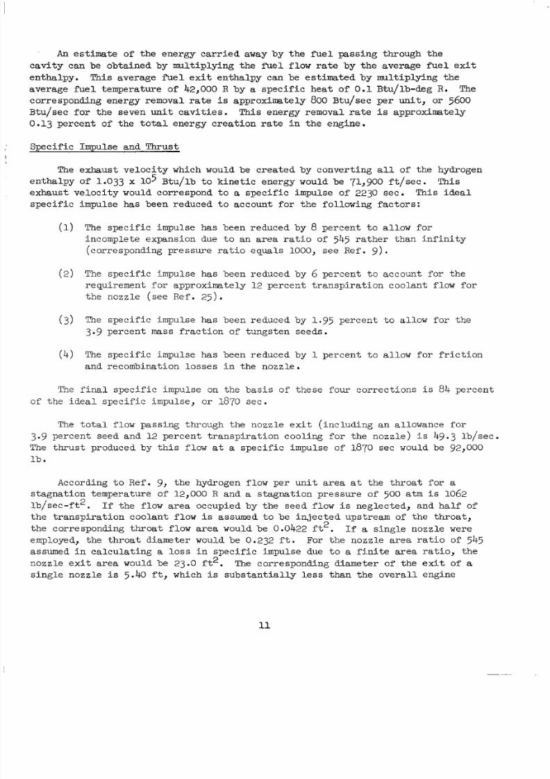
An es t im ate of the ener gy carr ie d away by the f u e l pass ing t h rough t he
c a v i t y c a n b e o b t a i n e d b y m u l t i p l y i n g t h e f u e l f l o w r a t e b y t h e a v e r a g e f u e l e x i t
en tha lpy .Thi save rage f u e l e x i t e n t h a l p y c a n be estimated b y m u l t i p l y in g h e
ave ragefue l empe ra tu reo f 42,000 R by a s p e c i f i c h e a t o f 0 .1 Btu/lb-deg R. The
corresponding energy removal r a t e i s approximate ly 800 B t u / s e c p e r u n i t , or 5600B t u / s e cf o r h es e v e nu n i tcav i t i e s .T h i se n e r g yr e m o v a lra t e i s approximate ly
0.13 p e r ce n t of t h e t o t a l e n e r g y c r e a t i o n r a t e i n t h e e n g i n e .
Spec i f icmpulsendhrus t
The exh aus t ve l oc i ty whichwouldbe c rea t ed by conve r t i ng a l l of the hydrogen
en tha lpyof 1.033 x lo5 B t u / l b o k i n e t i c e n e r g y w ouldbe71,900 f t / s ec . Th is
e x h a u s tve loc i t y wouldcorrespond t o a spec i f ic mpulseof 2230 se e. T h i s d e a l
spec i f i c mpul se ha s been reduced o account fo r he fo l l owing fac to r s :
(1) The spec i f ic impulse has been reduced by 8 p er , n en t t o a l l o w f o r
incompleteexpans ion due t o an a r ea ra t i o of 545 r a t h e r t h a n i n f i n i t y
( c o r r e s p o n d i n gp r e s s u r e r a t i oe q u a l s 1000, seeRef. 9 ) .
(2 ) The spec i f ic mpulse has been educedby 6 p e r c e n t oa c c o u n tf o r h e
requ i rement fo r approx ima te ly 12 p e r c e n t t r a n s p i r a ti o n c o o l a n t f l o w f o r
thenozz le seeRef . 2 5 ) .
(3) The spec ific mpu lse has been educedby 1.95 p e r c e n t o a l l o w f o r h e
3.9 p e r c e n t mass f r a c t i o n of t u n g st e n s e e d s.
( 4 ) The spec ific mpu lsehasbeen educedby 1 p e r c e n t o a l l o w f o r f r i c t i o n
and recombina ti on os se s i n t h e no zz l e .
The final spec i f i c mpu l se on t he b a s i s of thesef o u rcor rec t i ons i s 84 p e r c e n tof the dea ls p e c i f ic m p u l s e ,or 1870 se e.
The total f l ow p a s s i n g h r o u g h h e nozz l e ex i t ( i nc lud ing a n a l l o w a n c ef o r
3.9 pe rcen tseed and 12 p e r c e n t r a n s p i r a t i o n c o o l i n g f o r h e n o z z l e ) i s 49.3 l b / sec .
The thru s t pro duc ed by hi s f low a t a spec i f ic mpulse of1870secwouldbe 92,000
l b .According t o Ref. 9, thehydrogen f low pe run i ta rea a t t h e t h r o a t f o r a
stag nat io n emp eratu re of 12,000 R and a s t a g n a t i o n p r e s s u r e of500 atm i s 1062
l b / s e c - f t 2 . If thef lowareaoccup i edb y h eseedf low i s neglec ted,an dhalf of
t he t r ansp i ra t i on coo l an t f l ow i s assumed to be njec ted ups t ream of t he thr oa t ,
th ec o r r e s p o n d i n g h r o a tf l ow area wouldbe0.0422 ft2. If a s ing l enozz l e were
employed, th e hr oa tdiameter wouldbe0.232 f t . For t h e n o z z l e a r e a r a t i o of 54 5assumed in ca l c u l a t i n g a l o s s i n sp ec i f i c impul se due t o a f i n i t e area r a t i o , t h e
n o z z l e e x i t a r e a wouldbe23.0 f t 2 . The corresp ondin gdiameterof he ex i t of a
s ing l e n o z z l e i s 5.40 f t , which i s s u b s t a n t i a l l y l e s s t h a n h e o v e r a l l e n g i n e
11
8/2/2019 Nasa Report on Gas Core Nuclear Engines
http://slidepdf.com/reader/full/nasa-report-on-gas-core-nuclear-engines 16/105
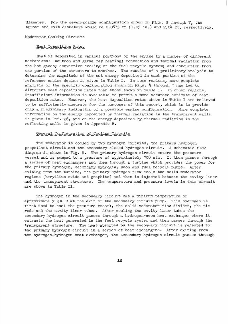
diame te r .For heseven-nozz l econ figu rat io n shown in F i g s . 2 through 7, t h e
t h r o a t a n d e x i tdia me ter s would be 0,0875 ft (1.05 i n . ) a n d 2.04 f t , r e s p e c t i v e l y .
ModeratorCool ing Ci rcui t s
"- """eatDe-position Rates
Heat i s d e p o s i t e d i n v a r i o u s p o r t i o n s of t h e e n g in e b y a number of different
mechanisms: neutronand g a m rayh e a t i n g ;convec t i onand he rma l ad i a t i on from
th eho tgase s ;convec t i vecoo l ing o f t he fue l r e c yc l e sys tem;andconduction rom
one po r t io n of th e s t r u c t u r e o a n o t h e r . The r e s u l t s o f a p r e l i m i n a r y a n a l y s i s o
determine hemagni tude of the ne t ener gy dep os i te d n each por t ion of t h e
re fe renceeng inedes ign i s g i v e n nT a b l e I. I n some re gi on s, more complete
ana lys i s o f t he spec i f i c conf igura t i on shown i n F i g s . 4 hrough 7 h a s l e d t o
d i f f e r e n t h e a td e p o s i t i o n ra t e s han ho se shown i n Tab le I. I n o t h e r r e g i o n s ,
i n s u f f i c i e n t i n f o r m a t i o n i s a v a i l a b l e t o p e r m i t a more acc ura te est ima te of heat
d e p o s i t i o n ra te s . However, th eh e a tdep os i t i o n a t e s shown i n Tab le I a r eb e l i e v e d
t o b e s u f f i c i e n t l y a c c u r a t e for t he purpose s o f h i s r epor t , which i s t o p r o v i d e
on ly a p r e l i m i n a r y n d i c a t i o n of a p o s s i b l ee n g i n eco nf ig ur at io n. More complete
in forma t ion on t he ene rgy depos i t ed by t he rma l r ad i a t i on i n t he t r anspa ren t walls
i s g i v e n i n R e f . 26 , and on t he ene rgy depos i t ed by the rma l r ad i a t i on i n t he
r e f l e c t i n g walls i s g iv en i n Appendix B.
The moderator i s cooledby two hydrogen circu i ts , he prim ary hyd rog en
p r o p e l l a n t c i r c u i ta n d h es e c o n d a r yc l o s e dh y d r o g e nc i r c u i t . A schematic low
diagram i s shown i n Fig . 8. The primaryh y d r o g e nc i rcu i ten t e r s hep r e s s u r e
v e s s e l a n d i s pumped t o a p r e s s u r e of approximate ly 708 atm. It thenpasses hrough
a s e r i e s of h e atexchangersand hen hrough a turbinewhichpro vid es he power f o r
theprimaryhydrogen,secondaryhydrogen,neonand uel ecycle pumps. Af ter
ex i t i ng from the u rb ine, hepr imary hydrogenf lowcools hesol idmodera tor
reg ions (be ry l l i um ox ide and g raph i t e ) and hen i s i n j e c t e d b e t w ee n h e c a v it y i n e r
a n d h e r a n s p a r e n ts t ruc tu re . The t em pe ra tu re a n d p r e s s u r e e v e l s n h i s c i r c u i t
a r e shown i n Table 11.
The hydrogen in th e se co nd ar y c i rc ui t has a minimum temperature of
approximate ly 300 R a t t h e e x i t of t h e s e c o n d a r yc ir cu it pump. Thishydrogen i s
f i r s t u s e d o c o o l h ep r e s s u r evesse l , he so l i d m o d e r a t o r flow d i v i d e r , t h e t i e
r o d sa n d h ec a v i t y i n e r u b e s .A f t e rc o o l i n g h ec a v i t y i n e r u b e s h e
secondaryhydrogen c i rcu i t pass es thro ugh a hydrogen-neon he at exc ha ng er where it
e x t r a c t s t h e h e a t g e n e r a t e d i n t h e f u e l r e c y c l e s y s t e m a n d t h e n p a s s e s t h r o u g h t h e
t r a n s p a r e n t s t r uc t ur e . The hea tabsorbedby heseconda ryc i rcui t i s r e j e c t e d t o
th ep r i m a r yh y d r o g e nc i rcu i t n a s e r i e s of h e a t e x c h a n g e r s .A f t e r exi t ing f rom
th e hydrogen-hydrogen he atexchanger , hesecondaryhydrogenc i rcui tpasses hrough
8/2/2019 Nasa Report on Gas Core Nuclear Engines
http://slidepdf.com/reader/full/nasa-report-on-gas-core-nuclear-engines 17/105
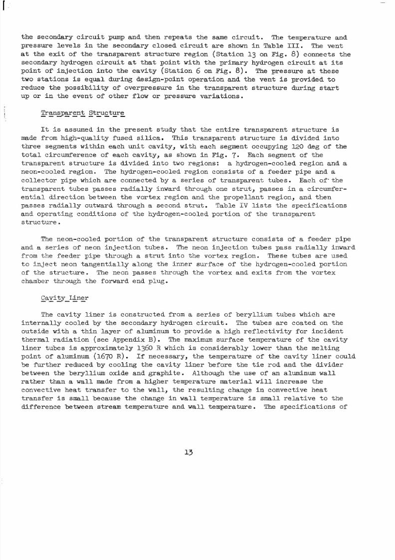
th es e c o n d a r yci rc ui t pump an d he nrepe a ts he same c i r c u i t . The tempera tureand
p r e s s u r e e v e l s n h e s e c o n d a r yc l o s e d c i r c u i t are shown i n Table 111. The vent
a t t h e e x i t o f h e r a n s p a r e n t s t r u c t u r e r e g i o n ( S t a t i o n 13 on Fig. 8 ) connec t s he
seconda ry hydrogen c i rcu i t a t that poin t wi th t he p r imary hydrogen c i rcu i t a t i t s
p o i n t o f n j e c t i o n n t o h e c a v i t y ( S t a t i o n 6 on Fig . 8 ) . The pressure a t t h e s e
two s t a t i ons i s equa l dur ing de s ign-po in t ope ra ti on and he ven t i s provided t o
r e d u c e h e p o s s i b i l i t y of o v e r p r e s s u r e n h e r a n s p a r e n t s t r u c t u r e d u r i n g s t a r t
up or i n t h e e v e n t o f o t h e r f l o w or p r e s s u r e v a r i a t io n s .
It i s assumed i n t h e p r e s e n t s t u d y t h a t t h e e n t i r e t r a n s p a r e n t s t r u c t u r e i s
made fromh i g h - q u a l i t y u s e ds i l i c a .T h i s r a n s p a r e n ts t r u c t u r e i s d i v i d e d n t o
three segme nts wi thin each uni t cavi ty , wi th each segmentoccupying 120 degof the
t o t a lc i r c u m f e r e n c e o feachcavi ty , as shown inF i g . 7. Each egmentof the
t r a n s p a r e n t s t r u c t u r e i s div ide d n to two reg ions : a hydrogen-cooled egionand a
neon- cooled egion . The hydro gen-co oled egioncons i s t so f a feede rp ipeand a
c o l l e c t o r pi p e which areconnec tedby a s e r i e s of t r anspa re n t ubes . Each o f ' t he
t r a n s p a r e n t u b e s p a s s e s r a d i a l l y n w a r d h r o u g h one s t r u t , p a s s e s i n a c i rcumfer-e n t i a l d i r e c t i o n b e t w e en th e v o r t ex re g i o n a n d t h e p r o p e ll a n t r e g io n , a n d t h e n
p a s s e sra di a l ly outward hrough a seconds t rut .Tab l e IV l i s t s t h es p e c i f i c a t i o n s
and opera t ing condi t ion s of thehydrogen-cooled por t ion of t he t r ans pa re n t
s t r u c t u r e
The neon-cooled p o r t i o no f h e r a n s p a r e n t s t r u c t u r econs i s t s o f a f e e d e rp i p e
and a s e r i e s o fneon in je c t i on ub es . The neon in j ec t ion ub es p a s sr a d i a l ly n w a r d
from th e eed erpipe hrough a s t r u t n t o h e v o r t e x re g i on . These t ubesa reu s e d
t o i n j e c t neon t a n g e n t i a l l y a l o n g t h e i n n e r s u r f a c e of t h ehydrogen-cooled por t ion
o f t h e s t ru c t ur e . The neon pas ses hro ugh hev o r t e xa n dexi t s f rom the v o r t e x
chamber t hr ou gh he forward endplug.
The ca v i t y l i n e r i s cons t ruc ted f rom a se r i e s o f b e ry l l i um tubes which a r e
in t e rna l l y c o o l e db y h es e c o n d a r yh y d r o g e ncir cu i t . The tub es a recoa t ed on the
o u t s i d e w i t h a th in la ye r of a luminum t o provide a h i g h r e f l e c t i v i t y f o r i n c i d e n t
t h e r m a lr a d i a t i o n (see Appendix B) . The maximum sur face empera tu re o f t he c a v i t y
l i n e r t u b e s i s approximate ly 1360 R which i s cons iderably ower han he mel t ing
point of aluminum (1670 R ) . If n e c e s s a r y , h e e m p e r a t u r eo f h ecav i t y i ne rc o u l d
Se f u r t h e r r e d u c e d b y c o o l i n g t h e c a v i t y l i n e r b e f o r e t h e t i e r o d a n d t h e d i v i d e r
between heberyl l iumoxideandgraphi te .Although heuseof an aluminum w a l l
r a t h e r t h a n a wall made from a highe r t empe ra tu re ma te r i a l w i l l i n c r e a s e t h ec o n v e c t i v e h e a t r a n s f e r o h e w a l l , t h e r e s u l t i n g change i n c o n v e c t i v e h e a t
t r a n s f e r i s small beca use he change i n w a l l t empera ture i s small r e l a t i v e t o t h e
differencebetweenstream emperatureand w a l l t empera ture . The sp ec i f ic a t io ns o f
8/2/2019 Nasa Report on Gas Core Nuclear Engines
http://slidepdf.com/reader/full/nasa-report-on-gas-core-nuclear-engines 18/105
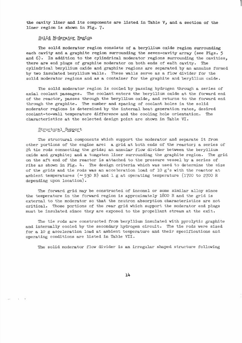
t h e c a v i t y l i n e r and i t s components are l i s t e d i n T a b l e V, and a s e c t i o n of t h e
l i n e r r e g i o n i s shown in Fig. 7.
The so l i d mod e ra to r r eg io n cons i s t s of a be ry l l i um ox ide reg ion surrounding
each cav i t y and a g r a p h i t e r e g i o n s u r r o u n d i n g t h e s e v e n - c a v i ty a r r a y (see Figs . 5
and 6 ) . In a d d i t i o n t o thecy l i ndr i ca lmode ra to r eg ionssur rounding hecavi t i es ,
t h e r e are endplugs of graphi temodera tor on bothendsof each cavi ty . The
c y l i n d r i c a l b e r y l l i u m o x i d e a n d g r a p h i t e r e g i o n s a r e s e p a r a t e d b yanannulusformed
by two insula ted b e r y l l i u m wal l s . These walls s e r v e as a f l o wd i v i d e rf o r h e
so l i d mode ra to r r eg ions and as a c o n t a i n e r for t h e g r a p h i t e a n d b e r y l l i u m o x i d e .
The sol id mo dera tor reg ion i s cooledbypassinghydrogen hrough a s e r i e s of
a x i a lc o o l a n tpass ages . The coo lante n t e r s h ebe ry l l i umo x i d e a t the orwardend
of t h e r e a c t o r , p a s s e s h r o u g h h e b e r y l l iu m o x i d e , a n d r e t u r n s o h e f o r w a r d e n d
through hegraphi te . Thenumber andspacing of c o o l a n th o l e s n h es o l i d
modera tor regions i s de t e rmined by t he i n t e rna l hea t gene ra t i on ra t e s , de s i red
coo l an t - t o -wa l l empe ra tu red i f fe rencea n d h ec o o l i n gh o l eor ienta t ion. Thec h a r a c t e r i s t i c s a t t he se l ec t e d de s ig n po in t a re shown i n Tab l e VI.
The s t r u c tu r a l componentswhich sup por t hemodera torandseparate it from
o t h e rp o r t i o n s of t h ee n g i n ea re : a g r i d a t bothends of th er e a c t o r ; a s e r i e s o f
24 t i e rods connec ti ng he g r ids; an annu l a r fl ow d iv ide r be tween he be ry ll i um
oxideandgraphi te ;and a t ungs t en i ne rsur rounding hegraphi te egion. The g r i d
on the a f t end of t h e r e a c t o r i s a t t a c h e d t o t h e p r e s s u r e v e s s e l by a s e r i e s o f
r i b s as shown i n F i g . 4 . The design cr i te r ia which was used t . 3 de t e rmine hes ize
o f t h e g r i d s a n d t i e r o d s was a n a c c e l e r a t i o n l o a d of 10 g ' s wi th t he reac to r a tambient emperatures (- 530 R ) and 1 g a t ope ra t i ng empera tu re (1700 o 2700 R
depending upon locat ion).
The for wa rd gri d may be con stru cted of i nco nel or some similar a l l o y s i n c e
t h e t e m p e r a t u r e i n t h e f o r w a r d r e g i o n i s approximate ly 1800 R a n d t h e g r i d i s
e x t e r n a l o h e m o d e r a t o r s o that t h e n e u t r o n a b s o r p t i o n c h a r a c t e r i s t i c s a r e n o t
c r i t i c a l . Those p o r t i o n s of t h e r e a r g r i d w h ic hsupport hemoderatorendplugs
mustbe i n s u l a t e d s i n c e t h e y a r e e x p o s e d to t h e p r o p e l l a n t s t r e a m a t t h e e x i t .
The t i e ro ds a r e co ns t ru c t e d from be ry l l i um insu l a t ed wi th pyro ly t i c g raph i t e
and n t e rna l l ycoo l ed b y h es e c o n d a r yh y d r o g e nc i rcu i t . The t i e ro d s were s i ze df o r a 10 g a c c e l e r a t i o n l o a d a t ambien t empe ra tu re and he i r spec i f i ca t i ons and
o p e r a t i n g c o n d i t i o n s a r e l i s t e d i n Table VII.
The sol id mod era to r f low divid er i s an r regu l a r shaped s t ruc tu re fo l l owing
8/2/2019 Nasa Report on Gas Core Nuclear Engines
http://slidepdf.com/reader/full/nasa-report-on-gas-core-nuclear-engines 19/105
t h eo u t e rcon tou rs o f t heberyl l iumoxide egion. The s t r uc tu re i s formed by two
be ry l l i um walls w i t h p y r o l y t i c g r a p h i t e i n s u l a t i o n on the outs ide and hydrogen
coo lan tpas s ingbe tween hebe ry l l i um walls. The spec i f i c a t i ons and ope ra t i n g
c o n d i t i o n s are shown i n Table VIII.
The ex t e r na l g rap h i t e con t a ine r i s a t h in -wa l l ed t ungs t en l i ne r which se rves
p r i m a r i l y as a f l owdiv ide rbe tween hegraph i t eand hepre s surevesse l . It a l s o
p r o v i d e s s u p p o r t t o t h e g r a p h i t e p i e c e s i n t h e e x t e r n a l m o d e r a t o r .
The s e c o n d a r y h y d r o g e n c i r c u i t t r a n s f e r s t h e e n e r g y a b s o r b e d i n c o o l i n g t h e
p r e s s u r evesse l , s u p p o r ts t r u c t u r e ,b e r y l l i u mo x i d e - g r a p h i t ef l o wd i v i d e r ,c av i t y
l i n e r , t r a n s p a r e n t walls and f u e l r e c y c l e s y s t e m t o t h e p r i m a r y h y d r o g e n c i r c u i t
v i a a s e r i e s o fhydrogen-to-hydrogenheatexchange rs . The spe c i f i c a t i o ns o r he s e
hea texchangers are shown i n Table IX. Seven heatexcha ngers were us ed s i n c e h i s
a l l o w s t h e f l o w f r o m e a c h c a v i t y t o b e p i p e d d i r e c t l y t o a heat exchanger without
a d d i t i o n a lm a n i f o l d i n g ;a l s o , h es ize of thehea texchangers i s s u c h t h a t h e y
may be in s t a l led n he sp ac e be tween he pumps and he p r e s s u r eve sse l . The highpre s sure por t i on o f t hepr imaryhydrogen c i rcui t (P - TOO a t m ) i s on the ube s ide
of thehea texchangersand hesecondaryhydrogen c i rcui t (P - 500 atm) i s on th e
s h e l l s i d e i n o r d e r t o minimize s h e l l h i c k n e s s .
The pr esen t coo lant f low scheme req uire s an extr eme ly complex piping and
manifolding ystem a s i n d i c a t e d nF i g s . 4 nd 5 . A t p r e s e n t h ep r e s s u r e o s s e s
a n d n s u l a t i o n e q u i r e m e n t s o r h ep ip ing havebeenest imated. The in su la t i on
th i ckness ha s been e s t ima ted ba sed on a 1775 R ope ra ti ng empera tu re i n t he fo rw ard
r e g i o nan dp y r o l y t i cgrap hi te nsu la t io n. The approximate hicknessof nsula t ion
r e q u i r e d i s 0.025 i n c h es o f i n s u l a t i o n p e r n c h of p i p e r a d i u s , a n d h i s
approximation was u s e d t o e s t i m a t e t h e i n s u l a t i o n w e i g h t r e q u i r e d .
The secondaryhydrogen ci rc u i t p ip in g may be ber yl l iu m from th e pump to t h e
fue l r e cyc l e hea t exchange r en t rance , s i nce he coo l an t empe ra tu re i s low ( < 1100 R ) .The m a n i f o l d i n g f r o m t h e g r a p h i t e o u t l e t t o t h e p r o p e l l a n t i n l e t r e g i o n mustbe
tungs t en i nce hecoo l an t empe ra tu re i s above 4000 R . The intermediate-temperature
piping, hefie1 recyc lehea texchangerand hehydrogen- to-hydrogen hea texchanger
(1600 R t o 2000 R t empe ra tu re range ) may be cons t ruc t ed from s t a i n l e s s s t e e l a l l o ys .
EngineWeight
Resu l t s o f a s tudy o de t e rmine he we igh t of a n u c l e a r l i g h t b u l b e n g i n e a r e
g i v e n n T a b l e X. The weightof mostof th e components i n Table X were made on t h eb a s i s o f c o n f i g u r a ti o n sd i s c u s s e d np r e c e d i n gse ct io ns . The turbopump weigh t was
determ ined.fr om he turbopump w eigh t giv en in Ref . 11w i t h a n a l l o w a n c e f o r d i f f e r -
ences neng inepre s sureandhydrogenflow . The miscel lan eousweightnoted in
8/2/2019 Nasa Report on Gas Core Nuclear Engines
http://slidepdf.com/reader/full/nasa-report-on-gas-core-nuclear-engines 20/105
Table X i nc ludes an a l l owance fo r exhaus t nozz l e s , fue l r e cyc l e sys t ems , and t he
equipment necessary o provide a m ag netic f i e l d w i t h i n t h e c a v i t y t o p r e v e n t
impingementof b e t a p a r t i c l e s on t h e c a v i t y walls ( see R e f . 2 7 ) .
P a r t i c u l a r a t t e n t i o n was d ev ot ed i n t h i s s t u d y t o d e t e r m i n i n g t h e w e i g h t of
t h e p r e s su r e v e s se l b e c a us e of t h e u n c e r t a i n t y i n p r e s s u r e v e s s e l w e i g h t n o t e d i n
Ref. 11. The pre sen t s tu dy was based on anana lys i s which i s d e s c r i b e d i n
Appendix A and which was made by the United Techno logy Center, a d i v i s i o n o f
Uni t edAi rc ra f tCo rp or atio n. Of fo ur p r e s s u r es h e l lconf igur a t i on s which a r e
co ns id er ed in Appendix A, t h e c o n f ig u r a ti o n of g r e a t e s t i n t e r e s t i s the one which
has a contourapproximate ly similar to he con tour shown in F ig . 4 and which
con ta ins s e v e nsepa ra t e h o l e s n h e a f t end for passageofseparatenozzles from
each of t he s e v e nu n i tcavi t i es . The ac tu a l volume enc l osed b y h ep r e s s u r es h e l l
co ns id er ed n Appendix A i s l e s s h a n h a t n F i g . 4. The pressure she l l f rom
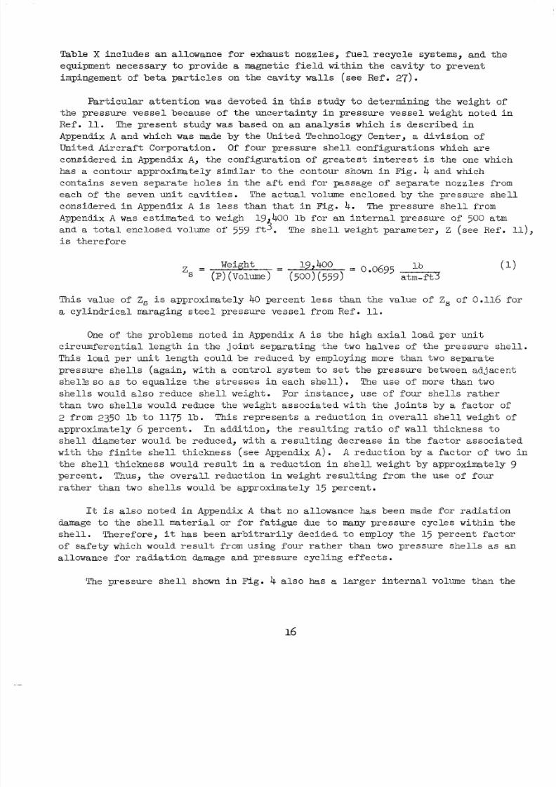
Appendix A was e s t i m a t e d t o w eig h19k400 l b f o r a n i n t e r n a l p r e s s u r e of500 atm
and a t o t a l en c lo se d volume of 559 f t s .
i s t h e r e f o r e
The she l l weig ht para mete r , Z (seeRef. ll),
(1)
Thi sva lue of Zs i s approximate ly 40 p e r c e n t e s s h a n h e va lue o f Zs of 0.116 f o r
a c y l i n d r i c a l m aragin g s t e e l p r e s s u r e v e s s e l fromRef. 11.
One of the pro blem s no ted i n Appendix A i s t h e h i g h a x i a l l o a d p e r u n i t
c i r c u m f e r e n t i a l l e n g t h i n t h e j o i n t s e p a r a t i n g t h e two h a l v e s o f h e p r e s s u r e s h e l l .
This load per uni t l ength could be reduced by employ ing more than two s epar a te
p r e s s u r e s h e l l s ( a g a i n , wi th a c o n t r o l s y s t e m o s e t h e p r e s s u r e b et we enadjacent
s h e l l s s o as t o e q u a l i z e h e s t r e s s e s i n e a c h s h e l l) . The us e of more tha n two
sh e l l s would a l so ed uces h e l lwe igh t . For ins tance ,use o f fou rs h e l l sr a t h e r
than two sh e l l s would reduce he weight assoc ia ted wi th he oint s by a f a c t o r o f
2 from 2350 l b t o 1175 l b .T h i s r e p r e s e n t s a r e d u c t i o n n o v e r a l l s h e l l w e i g h t o f
approximate ly 6 p e r c e n t . I n a d d i t i o n , h e r e s u l t i n g r a t i o o f wall t h i c k n e s s o
she l l d i am e te r wouldbereduced,with a r e s u l t i n g d e c r e a s e i n t h e f a c t o r a s s o c i a t e d
w i t h h e f i n i t e s h e l l h i c k n e s s ( s e e Appendix A ) . A reduc t i onb y a fa c t or of two i n
t h e s h e l l t h i c k n e s s would r e s u l t i n a r e d u c t i o n i n s h e l l w e i g h t b y a p p r o x i m a t e l y 9
pe rcen t . Thus, t h eo v e r a l l r e d u c t i o n nw e i g h tres ul t ing f rom theuse of fou r
ra t he r t ha n two sh e l l s wouldbeapproximately 15 pe rcen t .
It i s a l so no t e d i n Appendix A that no al lowance has been rnade f o r r ad ia t i o n
damage t o t he she l l ma te r i a l or f o r f a t i g u e due t o many p r e s s u r e c y c l e s w i t h i n h e
she l l .T h e r e f o r e , it h a s b e e n a r b i t r a r i l yde c id ed o employ the 15 p e r c e n tf a c t o r
of sa fe ty whichwould r e s u l t from us ing four r a the r t han two pre s su re she l l s as an
a l l ow ance fo r r ad i a t i on damage and p re s sure cyc l i ng e f fec t s .
The pr es su re sh e l l shown in F ig . 4 also has a l a r ge r i n t e r na l volume than he
16
8/2/2019 Nasa Report on Gas Core Nuclear Engines
http://slidepdf.com/reader/full/nasa-report-on-gas-core-nuclear-engines 21/105
pre s sure she l l con s ide r ed i n Appendix A by a fa c t or of approximate ly 1.57.Therefore , on th e ba s i s of Eq. (l), t h ep r e s s u r ev e s s e lw e i g h ts h o u l dbe nc rea sed
by a f a c t o r o f 1.57 toa p p r o x i m a t e l y 30,500 l b . Thi spre s surevesse lwe igh t i s
shown i n Table X .
ReferenceConfigurat ionDuringStartup
Two analyseshavebeen made t o de t e r mine t he s t a r t u p cha ra c t e r i s t i c s o f t he
re fe renceeng ined i scussed i n preced ingsect ions. The f i r s t a n a l y s i s i s based on
the use of a f i x e d n o z z l e t h r o a t area of 0.0398 f t 2 (exc lud ing he a l l owance fo r
half of t he ransp i ra t i oncoo l an t l ow -- seep r e c e d i n gsec t io n) . The second
a n a l y s i s i s based on the use of a var iable - thr oa t -a rea nozz le which w i l l maintain
a f i x ed neon d ens i t y a t t h eouts ide edgeof the uel-con tainment egion.Resul t s
of hese two ana ly ses a re desc r ibed n he fol lo wing two subsec t ion s .
Engine Sta rtu p wi th Fix ed Nozzle Throa t Area
The mass f low pass ing hrough he hroa tareaof here fe renceengine
d i scussed i n t he p reced ing sec t i on i s a f u n c ti o n of t h e t o t a l p r e s s u r e a n d t o t a ltempera tureof hehydrogenprope l lantups t ream of the hro a t . Res u l t s o f c a l cu-
l a t i on s of t h i s we igh t f l ow made us ing he pa rame te r s abu l a t ed n Re f . 9 a r e g i v e n
i n F i g . 9. The eng ine power ob tai ne dbymul t ip lying henozz le low i n Fig . 9 by
theen tha lpydetermined fromRef. 9 i s shown in F ig . 10.
The power c r ea ted in th e en gi ne i s p r o p o r t i o n a l t o t h e f o u r t h power o f h e
f u e l r a d i a t i n g t e m p e r a t u r e i f t h e r a t i o of r a d i a t e d e n e r g y t o t o t a l e n e r g y i s
independentofengine power. Fu el r a d i a t i n g e m p e r a t u r e sc a l c u l a t e d on t h i s b a s i s
u s i n g h e o t a l en gi ne powers gi ve n n F i g . 10 ar e shown in F ig . 11. The combi-
na t i ons of con d i t i on s i n F ig . 11w hich l e a d t o a p r o p e l l a n t e x i t t e m p e r a t u r e e q u a l
t o 80 pe rcen t of t he fue l r ad i a t i ng emp era tu re a re a l so nd i c a t ed on F igs . 9 and 10.
The den si t y of th e neon a t the edge of th e fu e l i s p r o p o r t i o n a l o e n g i n e
pre s sureand nve rse lypropor t i ona l o ue l ad i a t i ng empera tu re.Va lue s of neon
d e n s i t y a t the edge of the fue l de te r min ed f rom th e temp era tu res and pres sure s in
F i g . 11 a r eg i v e n nF i g . 12. A s noted on t h i s f i g u r e a n d n p r e c e d i n g f i g u r e s ,
thedes ignva lue of edge-of- fue ldens i t y i s 0.924 lb / f t3 . The co nd iti on s which
l e a d t o t h i s e d g e - o f - f u e l d e n s i t y a r e a l s o n o t e d on t h e c u r v e s i n F i g s . 9 through 11.
The f u e l d e n s i t y r e q u i r e d f o r c r i t i c a l i t y w i l l p r o b a bl y n o t be s i g n i f i c a n t l y
d i f f e r e n t d u r i n g s t a r t u p t h a n it i s dur ing ope ra t i on a t t h e e n g i n e d e s i g n p o i n t .
S i n c e t h e r a t i o o f a v e r a g e f u e l d e n s i t y t o edge -of - fue l dens i t y dur ing de s ign-po in t
ope ra t i on w i l l probab ly be cl o se to th e maximum value al low able from f l u i dmechanic s s t a b i l i t y con s id e ra t i o ns , it w i l l probab ly no t be poss ib l e t o ope ra t e
wi th a reducededge -of - fue ldens i tydur ingeng ines ta r tup. It can be seen rom
Fig. 12 t h a t o p e r a t i n g w i t h a p r o p e l l a n t e x i t t e m p e r a t u r e e q u a l t o 80 pe rcen t o f
t he edge -of - f ue l t empe ra tu re re su l t s i n ve ry low edge - of - fue l dens i t i e s dur ing
8/2/2019 Nasa Report on Gas Core Nuclear Engines
http://slidepdf.com/reader/full/nasa-report-on-gas-core-nuclear-engines 22/105
s t a r t u p . If t h e d e n s i t y a t t h e edge o f f u e l i s f i x e d a t 0.924 l b / f t 2 dur ing
s t a r t up , hee n g i n ep r e s s u r e san dw e i g h tfl ow s become extr eme lyhigh.Thiscanbe
p a r t i a l l y a v o i d e d b y t h e u s e of a var iable - thr oa t -a rea nozz le as d i s c u s s e d i n t h e
f o l l o w i n g s u b s e c t i o n .
Engine Sta r t up wi th Var i able NozzleThroatArea. - ..- - -~With a v a r i a b l e n o z z l e t h r o a t a r e a , it i s p o s s i b l e t o a d j u s t t h e d e n s i t y a t
t h e e d g e o f t h e f u e l - c o n t a i n m e n t r e g i o n t o a n y a r b i t r a r i l y s p e c i f i e d v a l u e
i n d e p e n d e n to f h echa rac t e r i s t i c s o f t heprope l l an tst r eam . The eng inepre s sure
requ i red t o ma in t a in an edge -of - f ue l dens i t y of 0 .924 l b / f t 3 i s shown i n F i g . 13
as a f u n c t i o n of f u e l r a d i a t i n g t e m p e r a t u r e ( p r e s s u r e i s i n v e r s e l y p r o p o r t i o n a l t o
f u e lr a d i a t i n g e m p e r a t u r e n h i sexa mp le) . The ene rg yc r e a t ed n h er e a c t o r i s
a ls o shown i n Fi g . 13 and i s p r o p o r t i o n a l t o t h e f o u r t h power of f u e l r a d i a t i n g
t empera tu re seep r e c e d i n gsec t io n). The hydrogen pr op el l ant low atep a s s i n g
t h r o u g h h e r e a c t o r i s a func t i on of t h e t o t a l power and t h e ra t i o of p ro pe l l an t
ex i t emp e ra tu re o ue l ad i a t i ng emp era tu re , Te/Tx. The e f fe c t of fu e l
rad i a t i ng empera tu re on t h i s w e i g h t f l o w i s shown i n F i g . 14 fo r va lue s o f Te/T*of 0 .5 and 0.8. Theseweight lows were det erm ine d b y div idi ng he ota l power by
t h e e n t h a l p y c o r r e s p o n d i n g o h e p r o p e l l a n t e x i t e m p e r a t u r e .
The e x h a u s t n o z z l e t h r o a t a r e a r e q u i r e d t o p a s s t h e p r o p e l l a n t f l o w i n d i c a t e d
i n Fig . 1 4 i s a ls o shown in t h i s same f igure .Th i snozz l earea was determined on
t h ebas i s of t he n forma t io n abu l a t ed i n Ref. 9. It canbeseen romFig. 1 4t h a t a r e d u c t i o n i n r a d i a t i n g t e m p e r a t u r e b y a fa c to r of 2 (wi th a corresponding
red uc t ion in eng ine power by a f a c t o r o f 1 6 ) w i l l r e s u l t i n a r e q u i r e d r e d u c t i o n
in n o z z l e h r o a t a r e a b y a f a c t o r o fapproximately 3. The mechanism required o
va ry t he t h roa t a rea must wi ths t and a high p re s s ure d i f fe ren t i a l ; however, s i nce
t h e a b s o l u t e a r e a s n v o l v e d a r e small, t h i s mechanism sho uld not be extremelyheavy.It mightbedesi rab l e t o employ wo d i f f e r en t h r oa t s : a f i x e d - g e o m e t ry r a n s p i r a ti o n -
coo l ed t h roa t for use a t high empera tures and a va r i ab l e -geome try h roa t oca t ed
downstreamof t he f i xed-geo me t ry h roa t fo r use a t lower temperatures.
Values of sp ecifi c mpu lsecor re sponding o he empera tu re sandpre s sure s
shown i n Figs . 13 and 1 4 a r eg i v e n nF i g . 15. Valuesofengine hrustdetermined
bymul t i p ly ingwe igh t l owbyspec i f i c mpul seareal so shown in F i g . 15. These
va lues o f t h ru s t were cor r ec t ed t o a l l ow for t h e t h r u s t o f t h e t r a n s p i r a t i o n
coo l an tf l ow i n the same manner as desc r ibed in a preced ingsec t ion.
18
8/2/2019 Nasa Report on Gas Core Nuclear Engines
http://slidepdf.com/reader/full/nasa-report-on-gas-core-nuclear-engines 23/105
VORTEX-STABILLZED O€!EN-CYCLE ENGINE
Pr inc ip l eofOpe ra t i on
The pr inc iple of opera t ion of an open- cyc le vor tex-s tabi l i zed engine (Refs. 2,
11 and24)
i s the same as that f o ra
v o r t e x - s t a b i l i z e d n u c l e a r l i g h tbulb
engine
except that the open -cycle engin e does not employ a p h y s i c a l t r a n s p a r e n t wal l
between he ue l -conta inmentandprope l lant egions . The open-cyc l eeng ine e l i e s
e n t i r e l y on f l u i d mechani cs phenomena t o p rov ide p re fe r en t i a l r e t en t i on o f t h e
nu c le ar fu e l . Becauseo f t h i s, heprimaryproblems i n suchanengine a re f l u i d
mechanic in n a t u r e . A s a r e s u l t , h e n v e s t i g a t i o n of t h ec h a r a c t e r i s t i c so fa n
open -cyc le vor tex- s tabi l i zed engine which w a s i n i t i a t e d a t t h e UAC Research
L a b o r a t o r i e s i n 1959 have concentrated on t h e f l u i d m ech an ic s c h a r a c t e r i s t i c s of
v o r t e x l o w .Extens ive nves t i ga t i o ns o f t hecha rac t e r i s t i c so fvor tex low have
i n d i c a t e d that t h e f u e l r e t e n t i o n c h a r a c t e r i s t i c s of t h i s e n g i n e a r e lower t h a n a r e
re qu ir ed from conomic co ns ide rat ion s. Summariesof t he sef l ui d mechanics in ve s t i -
g a t i o n sa r eg i v e n nR e f s . 2, 3 , 4 nd 5 . Although thise n g i n ed o e sn o ta p p e a r o
b e f e a s i b l e a t th ep r e s e n t i m e , h ere su l t s of s t u d i e s of t he c h a r a c t e r i s t i c s o f
th eeng inea redesc r ibed n hefo l l owingsec t i onsbecause o f t he pos s ib l e app l i -
c a t i o n of t h i s n f o r m a t i o n o o t h e r e n g i n e c o n c e p t s .
Spec i f i c Conf igura t i on a t Design Point
The re su l t s o f s t u d i e s o f t h e c h a r a c t e r i s t i c s o f a s p e c i f i c c o n f i g u r a t i o n o f
anopen-cyc l evor t ex-s t ab i l i z edeng ineareg iven i n Refs. 10 and 11. A ske t ch o f
theconf igura t i onchosen i s given i n Fig. 1 6 . The diameterof hec av it y i n t h i s
engine i s 6 f t and heave ragecav i t y eng th i s 6 f t . The c o n d i t i o n s n h e c a v i t y
of the e fe renceeng inedes ignareg iven i n Table X I . Thisengine was determined
t o have a spec i f ic mpulse of 2190 seeand a t h r u s t o f 1.45 x lo6 lb a c c o r d i n g oRef . 11. The f u e l d e n s i t y r a t i o n R e f . 11was based on a c r i t i c a l f u e l mass of
18.1 l b . However, e a r ly e s u l t s of more recent tud ies Ref . 1 4 ) have indica ted
t h a t t h e a c t u a l c r i t i c a l f u e l mass i s approx ima te ly wice h i s va lue , or 36.2 l b .
T h e r e f o r e , h e c o r re s p o n d i n g f u e l d e n s i t y r a t i o i s 10.0 r a t h e r h a n h e v a l u e of
5.O n o t e d i n R e f . 10 .
ModeratorConfiguration
Threemodi f ica t ions to he m o d e r a t o rconf igu ra t i on of t he spec i f i c g a s e o u s
nuc l ea r rocke t eng ine conf igura ti on p re sen ted n Re f . 11were i n v e s t i g a t e d t o
d e t e r m i n e h e i re f f e c t son
overal ldesignandperformance.Thesemodificat ionswere (1) e pl ac em e nt of t h e u n g s t e n i n e r u b e s w i t h p y r o l y t i c - g r a p h i t e - c o a t e d
b e r y l l i u m u b e s , ( 2 ) e l imin a t i on of t heheavywatermoderator,and (3) s u b s t i t u t i o n
of hydrogen f o r hel ium in hem o d e r a t o r coolant c i rc u i t . The spec i f i ccombina t i ons
of thesemodi f ica t ions whichwere i n v e s t i g a t e d a r e l i s t e d i n T a b l e XII. Configu-
r a t i o n A r e p r e s e n t s t h e o r i g i n a l d e s i g n o fRef. 11, Conf igura t i on B i n c o r p o r a t e s
8/2/2019 Nasa Report on Gas Core Nuclear Engines
http://slidepdf.com/reader/full/nasa-report-on-gas-core-nuclear-engines 24/105
modif ica t ion (1)above;Configurat ion C i ncorpora t e s m o d i f i c a t i o n s (1)and (2),
Conf igura t i on D i ncorpora t e s modi f i ca t i ons (1)and (3); an dConf igura t i on E i ncor -
p o r a t e s a l l t h e e of hemodi f ica t io ns . The e f fe c t s on the modera torconf igura t ion,
opera t ingcondi t ions ,andengineweight ,exc lus iveofpressurevesse l ,arediscussed.
The use o f be ry l l i um ine r ubes reduces he amount o f ungs t en n he nne r
l i ne r r eg ion and e l imina t e s t he b ime ta l l i c t ungs t en-b e ry l l i um jo in t s where t he
t u b e s o i n h eb e r y l l i u m i n e r . The b a s i cc o n f i g u r a t i o nof he i ne r ubes i s
s i m i l a r o h e o r i g i n a l d e s i g n a n d i s shown i n F i g . 8 ofRef. 11.
Becauseof t he h igh cav i t y w a l l t empera tures ( - 5000 R ) a n d t h e h i g h r a d i a n t
and convec t i ve hea t f l ux ( - 2360 Btu /sec- ft2) , the bery l l ium tube s mustbe
surroundedbyan nsula torsuch as p y r o l y t i c grap h i t e . The pyro ly t i cg r a p h i t e i s
coa ted wi th niobiumc ar bi de t o p r o t e c t it from thehothydrogen i n th e c a v i t y . I t
i s assumed t ha t t he p y r o l y t i c g r a p h i t e i s depos i t ed on t h e b e r y l l i u m u b e s n s u c h
a manner that t he t he rma l conduc t i v i t y i s low in t h e r a d i a l d i r e c t i o n (- 1.8 x lom4Btu/sec-f t -deg R ) and i s h i g h i n t h e c i r c u m f e r e n t i a l d i r e c t i o n ( - 1.7 x lom2Btu/sec-
f t -deg R ) . The r a t i o of p y r o l y t i cg r a p h i t e h i c k n e s s o h a l f circumference i s on
theorderof 0.3, and a comparisonof hequot ient of the hermal condu c t ivi ty and
d i s t a n c e p r e d i c t s a r e l a t i v e l y u n i f o r m c i r c u m f e r e n t i a l t e m p e r a t u r e d i s t r i b u t i o n .
The en t i r e su r fac e a re a of t he l i ne r t ube was used as a h e a t t r a n s f e r a r e a i n t h e
c a l c u l a t i o n of t h e f i l m t empe ra tu re d rop and he requ i red ube d i ame te r .
A c o m p a r i s o no f h ed e s i g ncha rac t e r i s t i c s o f h e i n e r u b e s f o r h ev a r i o u s
c o n f i g u r a t i o n s i s shown i n Table XIII. The operat ingc o n d i t i o n s o r h eb e r y l l i u m
t u b e c o n f i g u r a t i o n s a r e b a s e d on a m a x i m u m beryl l ium tempera tur e of 1500 R .
R e f e r r i n g t o C o n f i g u r a t i o n B, where helium i s used as a moderator coolant and
theheavywatermoderator i s pre sen t , he ca l cu l a t i ons p red i c t an ex t reme ly h igh
p r e s s u r e l o s s i n he ub es . The hea tgene ra t ed n heheavywa te rmode ra to r
inc re a se s t he minimum in l e t t em pe ra tu re t o t h e t u be s t o 900 R and al lows only 600 R
f o r a f i l m t empera tured ro p i n h e u b e s . The r e q u i r e d f i lm t empera turedropcan
be achieved only by a small tube diameter (- 0 .O3l i n . ) wi th a h i g h d y n a k c
p r e s s u r e (- 8 atm) or a change i n tube ength whichwouldmodify the inn er l in er
c o n f i g u r a t i o n . If theheavywater i s removed, the nle t empe ra tu re i s r e d u c e d o
564 R a n d t h e r e s u l t i n g c o n f i g u r a t i o n i s shown as Conf igura t i on C.
If hydrogen i s used as a c o o l a n t, t h e t o t a l p r e s s u r e l o s s i n t h e t u b e sdec rea se s by a f a c t o r o f 10, and the beryl l ium tubes could be used wi th the heavy
wa te r p re sen t (Conf igura t i on D ) or wi th the heavywater removed (Co nfig urat ion E ) .
20
8/2/2019 Nasa Report on Gas Core Nuclear Engines
http://slidepdf.com/reader/full/nasa-report-on-gas-core-nuclear-engines 25/105
The h ea t gen e ra t ed i n t he heavy water reg ion of the moderator i s approximate ly
9.0 x lo5 Btu/sec and, s ince the heavy water mustbe maintained a t a t empera ture
below 1000 R, it r e p r e s e n t s a re l a t i ve ly ow- t empera tu reh e a tso ur ce . The heavy
water mustbe cooled by he modera tor coolant before it e n t e r s t h e l i n e r t ubes , and
th e combined h ea t f rom the pre ssu re ves se l and the D20 raises t h e c o o l a n t i n l e t
t e m p e r a t u r e o 903 R . El imina t i onof he D20 l o w e r s h e u b e n l e t e m p e r a t u r e o
564 R, e l i m i n a t e s t h e D20 hea t exchange rs and c i rcu l a ti on sys t em, and e l imina t es
th eo u t e rc o n t a i n m e n tshe l l of t h e D20 regi on. The thick nessof hebe ry l l i um
oxide and g raph i t e r eg ions i s i nc rea sed i n o r d e r t o m a i n t a i n t h e 4500 R o u t l e t
tempera ture .
The ch a r ac t e r i s t i c s of t hemoderatorregionwith heheavywater removed
(Conf igura t i ons C and E ) are compared with he des ign o f R e f . 11 i n T ab le X I V . I n
a d d i t i o n t o t h e w e i g h t s a v i n g i n t h e s o l i d m o d e r a t o r w hich i s shown in t h e t ab l e ,
t h e r e i s a decrease of 4.3 i n . i n t h e i n s i d e r a d i u s of t h e p r e s s u r e v e s s e l which
would reduce he pressure vessel weight .
The useofhydrogen as a modera tor coolant permi t s a reduc t i on by a f a c t o r o f
3 .2 i n themodera torcoolantf low r a t e s i f t he empera tu r e eve l s a re ma in t a ined a t
the same levels as s p e c i f i e d n h ep r e l i m i n a r y d e s i g n . T h i s r e d u c t i o n n f l o w
r a t e i s more than enough t o o f f s e t t h e d e c r e a s e s i n f l u i d d e n s i t y , a n d t h e dynamic
p r e s s u r e i s reducedby a f a c t o r o f 5 t o 10 depending on t h e f l u i d e m p e r a t u r e . I f
a l l of the cool ing hole and piping dimens io ns a re he ld cons tant , he ota l coolant
pres sur e dro p wouldbe red uced from 35 t o 7 a t m an d th e pumping power re qu ire me nts
reduced .Anothe ra l te rna t ive i s t o r ed u ce h epipingandheatexchangerdimensions
ino r d e r or e d u c e h ee n g i n ew e i g h t . A comparison of pipings izesandwe igh t s i s
shown i n Table XV A rede s ign of thehigh-temperatureheatexchanger showed a 40p e r c e n t r e d u c t i o n i n t h e w e i g h t was poss ib l e wi th a hydrogen moderator coolant.
The useofhydrogen as a moderatorcoolant makes it n e c e s s a r y t o c o a t t h e
graph it e modera to r wi th n iob ium ca rb ide i n o r de r t o p r o t ec t it f rom a t tack by he
hothydrogen. The qu an ti ty of niobium car bid enecessa ry as a func t i on o f p re s sure
drop i n he g r a p h i t e r e g i o n i s shown i n F i g . 17. T h i s p l o t i s based on th e
graph i t e h i ckness used n eng ine Conf igura t i on D (8.7 i n . ) a n d a 0.002 i n .
n iobiumcarbidecoa t ing on t h e c o o l i n g h o l e s u r f a c e s . I n add i t i o n o he n iobium
ca rb ide on thecoo l ingpassages ,approx ima te ly 15 l b a r e r e q u i r e d t o c o a t t h e
g r a p h i t e i n t h e r e g i o n o f t h e p r o p e l l a n t a n d c o o l a n t i n l e t s .
EngineWeight
A comparisono f t o t a l e n g i n e w e i g h t e x c l u s i v e o f p r e s s u r e s h e l l f o r t h e
c o n f i g u r a t i o n s n v e s t i g a t e d i s shown i n Table XVI I n a d d i t i o n t o t o t a l w e i g h t s ,
21
8/2/2019 Nasa Report on Gas Core Nuclear Engines
http://slidepdf.com/reader/full/nasa-report-on-gas-core-nuclear-engines 26/105
the abso rbin g a rea of the tungs ten-184 and niobium carbide a re l i s t e d t o show th e
r e l a t i v e a mo un tsofneutronabsorbillg materials p r e s e n t i n t h e v a r i o u s c o n f i g u -
r a t i o n s .
The l a r g e s t u n c e r t a i n t y i n t h e e s t i m a t e of t h e w e i g ht o f h e o v e r al l
c o n f i g u r a t i o n in Ref. 11w a s due t o u n c e r t a i n t y i n t h e w e i g h t of t h e p r e s s u r e
v e s s e l . A s n o t e d n Table X I V ofRef. 11, t h ee s t ima te so fp r e s s u r ev e s s e lw e i g h t
v a r i e d from 30,000 t o 125,000 l b . The studiesconduc t ed a t theUnitedTechnology
Center Division of United Aircraft Corp orat ion (see AppendixqA ) permi t a more
accura t ee s t ima te ob e made of th ep r e s s u r evesse lweig ht . These es t im ates of
pre ssu re ve sse l we igh t were made on t h e b a s i s of a value of theparameter Z, D f
a0 6 9 5 lb / f t3-a tm see Eq. (1)). The volumes w it h in h ep r e s s u r es h e l l e q u i r e d n
the e s t ima t ion o f p re s sure ve s se l we igh t a re g iven i n t he uppe r row o f Table XVII
f o reac h of theeng ineconf igura t i onsno t ed nTab le X I I . The corresponding
w e i g h t so f h ep r e s s u r ev e s s e l ar e shown i n t h e second row. The t h i r d row co nta ins
weights ofcomponents ot he r ha n hep r e s s u r evesse l f romTable XVI The fourth
and l a s t row indica tes th e t o t a l w e i g h t of t h e o v e r a l l c o n f i g u r a t i o n .
I n t e r p r e t a t i o n o f F u el Loss RateParameters
Cr i t e r i a fo r Acce p t ab l e Fue l Loss Ra t e
In the fo l l owingd i scuss ion , it i s assumed that economics w i l l govern he
minimum accep table lo ss r a te of n uc lear fue l f rom a gaseous nuc l ea r rocke t eng ine .
In determining t h i s a c c e p t a b l e f u e l loss r a t e , it i s n e c e s s a r y t o s p e c i f y a miss ion
for theeng ine . In t he o l l owingd i scuss ion , hemis s ioncons ide red w i l l be that
of Ref. 17 n which the gaseous-nuc lear- rocke t-powered vehic le i s boos ted by a
Sa turn I - C l aun ch veh i c l e , a f t e r which t hegaseousnuc learrocke tengine i s
employed t o a c c e l e r a t e t h e v e h i c l e i n t o o r b i t a n d t h e n c e t o a ve lo c i t y 50 ,000 f t / s e c
g r e a t e r h a n o r b i t a l v e l o c i t y . It i s assumed tha t here i s one gaseousnuc lear
rocke teng ines tageand two tank agestag es. The en gi nec o n s i d e r e d n h ea n a l y s e s
i s assumed t o have t h e c h a r a c t e r i s t i c s d i s c u s s e d i n t h e p r e c e d i n g s e c t i o n ( s e e
Table XI). According to F i g . 76 of Ref. 17, h i se n g i n ecou ld be us ed o
a c c e l e r a t e a payload of285,000 lb hr ou gh heve loc i t y nc rementc o n s i d e r e d . If
there were no l o s s of nu c l e a r fue l , t he t o t a l p ro pe l l an t consumed by hegaseous
nuc lear rock et wouldbe approximately 875,000 lb , and the cos t wouldbe $225 pe r
l b of payload on t h e b a s i s of t h e n f o r m a t i o n n F i g . 100 ofRef. 17.
The per mis s ib le fue l loss r a t e must be udged on th e bas is of t he d i f fe renc e
i n mi s s ion cos ts c a l cu la t ed us ing ga seous nuc l ear rocke t s and so l i d -core nuc l ea r
rockets .According t o Table V ofRef. 17, t h ecos t of us ing ours tages of sol id-c o r e n u c l e a r r o c k e t s i n a suborbi t -s tart mode wouldbe$2,426 p er lb ofpayload for
the same missioncons idered or hegaseousnuclear ocket . Thus th ep o t e n t i a l
savings that could be accrued by us ing a gaseous -core nuc l ea r rocke t p rov id ing
pe r fec tcon t a inmentra the r hanso l i d -corenuc l ea rrocke t s i s $2,426minus $225 o r
22
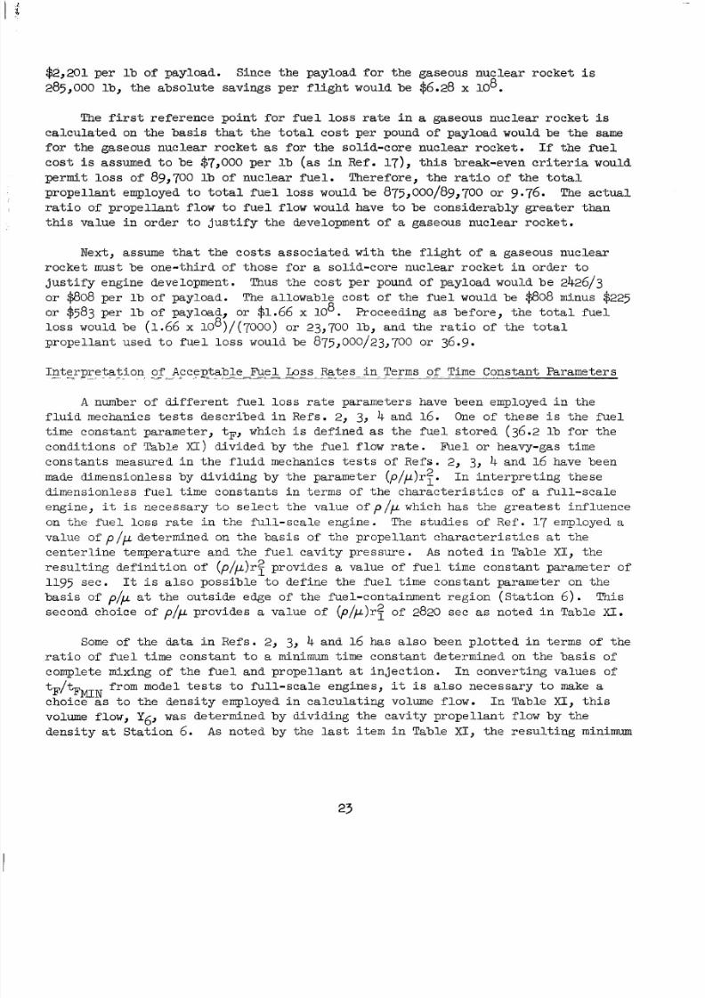
8/2/2019 Nasa Report on Gas Core Nuclear Engines
http://slidepdf.com/reader/full/nasa-report-on-gas-core-nuclear-engines 27/105
$2,201 p er l b ofpayload.Since hepayload or hegaseousnuc lear ocke t i s
285,000 lb , t h e a b s o l u t e s a v i n g s p e r f l i g h t wouldbe $6.28x lo8.
The f i r s t r e f e r e n c e p o i n t f o r f u e l loss r a t e i n a gaseous nuc l ea r rocke t i s
c a l c u l a t e d on t h e b a s i s that t h e t o t a l c o s t p e r poundof payloadwouldbe th e same
for hegaseousnuc l ea r ocke t as f o r h es o l i d - c o r en u c l e a r o c k e t . If t h e f u e l
c o s t i s assumed t o be $7,000 p e r l b (as i n R e f . l7), t h i s b r e a k - e v e n c r i t e ri a w ould
permi t loss of89,700 l b o fn u c l e a rf u e l .T h e r e f o r e , h er a t i oo f h e o t a l
p r o p e l l an t employed t o t o t a l f u e l l o s s wouldbe875,000/89,700 or 9.76. The actual
r a t i o of p r o p e l l a n t f l o w t o f u e l f l o w wouldhave t o be cons ide rab ly g rea t e r t han
t h i s v a l u e i n o r d e r t o j u s t i f y t h e developm entof a gaseous nuc l ea r rocke t .
Next,assume t h a t t h e c o s t s a s s o c i a t e d w i t h t h e f l i g h t of a gaseousnuc lear
rocke t mustbe one - th i rd o f t hose fo r a s o l i d - c o r e n u c l e a r r o c k e t i n o r d e r t o
ju s t i fy en gi ne development. Thus the cos t per pound ofpayloadwouldbe2426/3
o r $808 p e r l b ofpayload. The al lo wa ble cos t of th e fu e l wouldbe $808 minus $225
or $583 pe r bofpay load , or $1.66 x lo8. Proceeding as b e f o r e , h e o t a l f u e l
loss wouldbe (1.66 x 10⁸)/(7000) o r 23,700 lb , a n d h e r a t i o of t h e t o t a l
p r o p e l l a n t u s e d t o f u e l loss wouldbe875,000/23,700 o r 36.9.
I n t e r p r e t a t i o n. ". . . . . of- " cceptabJe-&e&. - -"-" Logs. Ra tes -in - Terms o f Time Co nsta nt Par ame ters
A number o f d i f f e r en t fu e l l o s s r a t e pa rame te r s havebeenemployed in th e
f l u i d mechan ics t e s t s d e s c r i b e d n R e f s . 2, 3, 4 nd 16. One of these i s t h e f u e l
t imecons tantparameter , tF, which i s de f ined as t h e f u e l s t o r e d (36.2 l b f o r t h e
co nd i t io ns of Table X I ) d i v i d e d b y h ef u e lf l o w r a t e .F u e l or heavy-gas ime
constants measured in t h e f l u i d mechanic s t e s t s o f Re fs . 2 , 3, 4 and 16 havebeen
made dimensionlessbydividingby heparameter (p/,u)r:. I n n t e r p r e t i n g h e s e
d i m e n s i o n l e s sf u e l i m ec o n s t a n t s n e r m s of t h e c h a r a c t e r i s t i c s of a f u l l - s c a l e
engine, it i s n e c e s s a r y t o s e l e c t t h e v a l u e of p/,u which has the grea tes t inf luenceon t h e f u e l l o s s r a t e n h e f u l l - s c a l een gi ne . The s tu di es of Ref . 1 7 employed a
value o f p / p determined on t h e b a s i s of t h e p r o p e l l a n t c h a r a c t e r i s t i c s a t t h e
c e n t e r l i n e e m p e r a t u r ea n d h ef u e lc a v i t yp r e s s u r e . A s n o t e d nT a b l e X I , t h e
r e s u l t i n g d e f i n i t i o n o f (p/,u)rf provides a va lueo ffue l imecons t an tparameter of
1195 see . I t i s a l soposs ib l e od e f i n e h e u e l i m ec o n s t a n tp a r a m e t e r on t h e
bas is of p/p a t th eou t s ideedgeof he ue l -con t a inment eg ion S t a t i on 6 ) . This
secondchoiceof p/p prov ides a value of (p /p)r : of 2820 see as n o t e d i n T a b l e XISome of t h e data i n R e f s . 2, 3, 4 and 16 has a l s o b e e n p l o t t e d n e r m s of t h e
r a t i o of f u e l t i m e c o n s t a n t t o a minimum tim e co ns tan t de ter mi ne d on t h e b a s i s of
completemixingof he f u e l an dp r o p e l l a n t a t i n j e c t i o n . In conve r t i ngva lues of
choice as t o h e d en si ty employed in ca lc ul a t in g volume f low. In Table XI t h i s
volume flow, Y6r was de t e rmined by d iv id ing he cav i t y p rope l l an t f l ow by he
d e n s i t y a t S t a t i o n 6. As notedby he l a s t i t e m nT a b l e XI, t h e r e s u l t i n g m i n i m
from model t e s t s t o f u l l - s c a l e e n g i n e s , it i s a l s o n e c e s s a r y t o make a
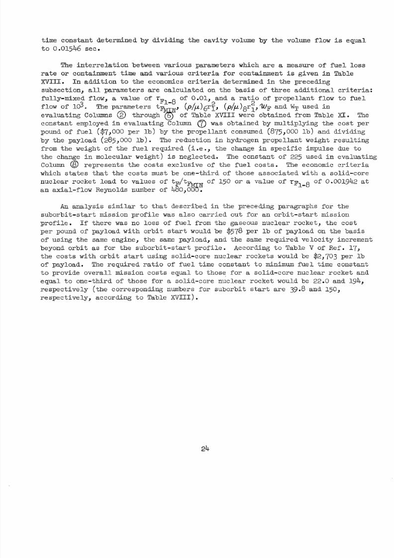
8/2/2019 Nasa Report on Gas Core Nuclear Engines
http://slidepdf.com/reader/full/nasa-report-on-gas-core-nuclear-engines 28/105
t ime con s tant de te r min ed by divid ing the cavi t y volume by th e volume flow i s e q u a l
t o 0 .0 15 46see.
The i n t e r r e l a t i o n be tween va r ious pa rame te r s which are a measure of f u e l loss
r a t e or con t a inment ime and var ious c r it e r i a fo r con t a inment i s g i v e n i n T a b l e
XVIII. I n a d d i t i o n t o the economics criteriad e t e r m i n ed n h ep r e c e d i n g
subsec t i on , a l l pa rame te r s a re ca l cu l a t ed on t h e b a s i s of t h r e e a d d i t i o n a l c r i t e r i a :ful ly-mixed low, a value of r of 0.01, and a r a t i o of p r o p e l l an t l o w o u el
flow f 103. m ep a r a m e t e r s t
eva lua t i ng Columns @ through%ofTable X V I I I were obt ain ed fromTable XI. The
cons t an t employed i n ev a l ua t i ng Column 0 as obta ined by mul t ip ly ing he cos t pe r
poundof f u e l ($7,000 p er b) by he pr op el lan t consumed (875,000 l b ) anddividing
by hepayload (285,000 l b ) . The re du c t i on n hydro genprope l l an twe igh t e su l t i ng
from theweightof th e f u e l r e q u i r e d ( i . e . , t h e change i n s p e c i f i c im pu lsedu e t o
the change inm o l e c u l a rw e i g h t ) i s neg lecte d. The co nst ant of 225 us ed ne v a l u a t i n g
Column @ r e p r e s e n t s h ec o s t se x c l u s i v e of t h e u e lco s t s . The economic c r i t e r i a
which s t a t e s that t he cos t s mustbe one - th i rd of t hose a s soc i a t ed wi th a so l i d -core
n u c l e a r o c k e t ead t o va lues f tF / t o f 150 o r a value o f r F o f 0.001942 a ta n a x i a l - f low Reynolds number of 480,%!
F1-8(P//1)6rf~ (p/p)8'1>wFand WT u s e d i n
N'
1-8
An a n a l y s i s similar t o t h a t d e s c r i b e d n h e p r e c e d i n g p a r a g r a p h s f o r h e
s u b o r b i t - s t a r t m i s s i o n p r o f i l e was a l s o c a r r i e d o u t f o r a n o r b i t - s ta r t m i s s i o n
p r o f i l e . If t h e r e was no l o s s o f f u e l f rom thegaseousnuc l ea r ocke t , hecos t
per pound of payload w i t h o r b i t s t a r t wouldbe $578 per l b of payload on the b a s i s
of us in g he same eng ine, he same payload ,and he same req uir ed ve loc i t y nc rement
beyond orbi t as f o r h e s u b o r b i t - s t a r t prof i le . According t o Table V ofRef. 17,t h e c o s t s w i t h o r b i t s t a r t us ing so l i d -core nuc l ea r rocke t s wouldbe$2,703 per l b
of payload. The r e q u i r e d r a t i o of f u e l i m ec o n s t a n t t o minimum fuel imec o n s t a n t
t o p r o v i d e o v e r a l l m i s s i o n c o s t s e q u a l t o t h o s e f o r a so l i d -core nuc l ea r rocke t and
e q u a l t o o n e - t h i r d of t h o s e f o r a so l i d -core nuc l ea r rocke t wouldbe22.0and 194,r e s p e c t i v e l y ( the corresponding numbers f or sub or bi t s t a r t a r e 39.8 an d150,
re spec t i ve ly , a c c o r d i n g t o Table XVIII).
24
8/2/2019 Nasa Report on Gas Core Nuclear Engines
http://slidepdf.com/reader/full/nasa-report-on-gas-core-nuclear-engines 29/105
REFERFNCES
1. Ragsdale,Robert G. andFrank E. Rom: Gas-Core Reactor Work a t NMA/Lewis.
A I M Paper NO. 67-499 presented a t t h e AIM 3rd P ropu l s ion Jo in t Spec i a l i s t
Conference,Washington, D. C. , uly 17-21? 1967.
2.Clark, J . W. , . S. Kendall , B. V. Johnson, A. E. Mensing, and A. Travers :Summary of Gaseous Nu cle ar Ro ck et Flu id Mechanics ResearchConductedUnder
Contract NASw-847. UAC ResearchLabora tor iesRe po rt F-910091-13 pr epa red
underContract NASw-847,May 1967. To be ssued as NASA CR r e p o r t .
3. Kendal l , J . S . , A . E. Mensing, and B. V . Johnson:ContainmentExperiments i n
Vortex Tubes withRadialOutflowandLargeSuperimposedAxialFlows. UAC
Re sea rch Lab ora tor ies Re po rt F-910091-12 pr ep are d un der Co ntr act NASw-847,
May 1967. To be issued as NASA CR r e p o r t .
4 . Johnson, B. V. : Exploratory Flow andCoctainmentExperiments i n a Direc ted-
Wall-Jet Vortex Tube with Radia l OutflowandModerateSuperimposedAxialFlows.UAC ResearchLaboratoriesReportF-910091-11preparedunderContract NASw-847,
May 1967. To be issued as NASA CR r e p o r t .
5 . Travers , A . : Exper imen ta l nves t iga t ionof Flow Pat te rns nRadia l -Out f l ow
VortexesUsing a Rota t ing-Per iphera l -wal l Water Vortex Tube. UAC Research
Labora tor iesReport F-910091-10 preparedunderContract NASw-847,May 1967.
To be issued as NASA CR r e p o r t .
6. Krasce l la , N . L.: Theore t i c a l nves t i ga t i ono f h eA b s o r p t i v ePrope r t i e so f
S m a l lPa r t i c l e san d Heavy-Atom Gas es. UAC ResearchLabora tor iesRepor t
E-910092-7 preparedunderCon tr ac t NASw-847, Septe mb er 1966. Also ssued as
NASA CR-693.
7. Kinney, R . B .: Theore t ica lEffec tofSeedOpaci ty ndTurbulence onTemperature
Di s t r i bu t i o ns n he P rop e l l an t Reg ionof a Vortex-Stabi l ized Gaseous Nuclear
Rocket. UAC ResearchLaboratoriesRep ort E-910092-8 prep aredunderContract
NASw-847, September 1966. Also ssued as NASA CR-694.
8. Kesten, A . S . and N. L. Krasce l l a :Theore t i c a l nves t i ga t i ono fRadiant Heat
T r a n s f e r n h e F u e l R egionof a Gaseous NuclearRocketEngine. UAC Research
Labora tor iesRe po rt E-910092-9 pre pare dunderContr ac t NASw-847, Sep tember 1966.
Also issued as NASA CR-695.
9. Roback, R . : Theoret icalPerformance o f RocketEnginesUsingGaseous Hydrogen
i n h e I d e a l S t a t e a t Stagnat ionTemperaturesup t o 200,000 R . UAC Research
Labora tor iesRe po rt E-910093-30 pre par edunderContract NASw-847. Also i s s u e d
as NASA CR-696.
8/2/2019 Nasa Report on Gas Core Nuclear Engines
http://slidepdf.com/reader/full/nasa-report-on-gas-core-nuclear-engines 30/105
REPERENCES (Cont 'd)
10.
11.
12.
13.
1 4 .
15.
16.
Latham, T. S . : N u c l e a rC r i t i c a l i t yS t u d yo f a Spec i f icVortex-Stabi l i zed
Gaseous NuclearRocketEngine. UAC ResearchLaboratoriesReport E-910375-1
preparedunderCont rac t NASW-847,September 1966. Also i s sued as NASA CR-697.
McLafferty, G. H. ,. E . B u e r , n d D. E . Sheldon:Prel iminaryConceptual
DesignStudy of a Spec ific-V ortex -Stab i l ized Gaseous NuclearRocketEngine.
UAC ResearchLaboratoriesRep ort E-910093-29 pr epa red underCont rac t ~ ~ ~ w - 8 4 7 ,September 1966. Also ssued as NASA CR-698.
Douglas, F. C . , R . Gagosz, and M . A. IkCrescente :Opt ica lAbsorp t i on n
TransparentMateria lsFol lowingHigh-TemperatureReactor rradiat ion. UAC
ResearchLaboratoriesRep ort F-910485-2 prep ared underContract N ~ W - 8 4 7 ,
September 1967. To be issued as NASA CR r e p o r t .
GagOsz, R . , J . Waters, F. C . Douglas, and M . A. DeCrescente:OpticalAbsorpt ion
i nF u s e dSil ica During T R I G A Reactor Pulse I r r a d i a t i o n s . UAC Research
LaboratoriesReportF-910485-1preparedunderContract l!L&3w-847, September 1967.To be issued as NASA CR r e p o r t .
Travers, A.: Exper imenta l nves t iga t ion of Radial-InflowVortexes in J e t -
Injec t ionandRota t ing-Per iphera l -Wal l Water VortexTubes. UAC ResearchLabora tor iesReport F-910091-14 preparedunderCon tr ac t NAsw-847, Septem ber
1967. To be issued as NASA CR r e p o r t .
Kendal l , J . S. : Exper imenta l nves t iga t ionof Heavy-Gas Containment i n
Constant-TemperatureRadial-InflowVortexes. UAC ResearchLaboratoriesRepor t
F-910091-15 preparedunderCont rac t ~ M w - 8 4 7 , September 1967. To be issued
as NASA CR r e p o r t .
McLafferty, G. H . : Analyt ica lS tudyof hePe r fo rmanceCharac te r i s t i csof
Vo rte x-S tab iliz ed Gaseous Nuclear Rocket Engin es. UAC ResearchLaboratories
Report D-910093-20 preparedunderCont rac t NMw-847, September 1965. To bei s sued as NASA CR r e p o r t .
McLafferty, G . H., H. H. Michels, T . S. Latham, and R . Roback: Analytical
Studyof Hydrogen Turbopump C y cl es o r Advanced Nu cle arRockets . UAC Research
LaboratoriesRe po rt D-910093-19 pr epa redunderContr ac t NASw-847, Septem ber
1965. Also ssued as NASA CR-68988.
26
8/2/2019 Nasa Report on Gas Core Nuclear Engines
http://slidepdf.com/reader/full/nasa-report-on-gas-core-nuclear-engines 31/105
REFERENCES (Cont ' d )
19. Patch, R . W .: Methods forCalcula t ingRadian t Heat Tr an sf er n High-Temperature
w d r o g e n Gas. UAC ResearchLabora tor iesReport "1492-1,November 1961.
20. Marteney,P. J. : Exper imenta l nves t iga t ion of th eOpac i t yo fS m a l lPa r t i c l e s .
UAC Res earch Lab orat ories Rep ort C-910092-2 prepare d under Contra ct N ~ W- 8 4 7 ,September 1964. Also i s sued as NASA CR-211.
21.Lanzo, C . D. and R . G . Ragsda le :Exper imenta l&termina t ion of Spec t ra l nd
T o t a lTra nsm iss i vi t i es of Clouds of Sm al lP a r t i c l e s . NASA Technical Note
D-1405, September1962.
22. Lanzo, C . D. and R . G. Ragsdale: Heat T r a n s f e r o a SeededFlowing Gas From
an Arc Enclos ed by a Quart z Tube. NASA Technical Memorandum X-52005, June 1964.
23. chneiderman, S. B . : Theore t i c a lVi scos i t i e s ndDif fus ivi t ies n High-
TemperatureMixturesof Hydrogen and Uranium. UAC ResearchLaboratoriesReportC-910099-1 preparedunderCont rac t NMw-847, September 1964. Also ssued as
NASA CR-213.
25.McLafferty, G. H . : Approximate Limitationson heSp ec if ic Impulse f Advanced
NuclearRocketEngines Due t o NozzleCoolantRequirements. UAC Research
Labora tor iesReport D-110224-1, April 1965.
26. McLa fferty, George H . : Absorp t i onofThe rma lRadia t i on n heTranspa ren t Wall
of a NuclearLight Bulb Rock etEngine. ournal of SpacecraftandRockets,
v o l . 4, NO. 6, 1967.
27.McLafferty, G . H . : Analyt ica lStudyofModera tor Wall Cooling of Gaseous
Nuclear Rocket Engines. UAC ResearchLaboratoriesReport C-910093-9 prepared
underCon tr ac t NASw-847, September 1964. A l s o i s sued as NASA CR-214.
28. Darms, F. J., R . Molho, and B. E . Ch est er: Improved ilament-Wound Co ns tr uc tio n
f o rC y l i n d r i c a l P r e s s u r e Vessels. Aero jet-G ener alCorpora t ion,preparedunder
Contract No. AF 33(616)-8442.Technical Documentary Rep ort No.ML-TDR-64-43,
Vol. I, March 1964.
29. Soffe r ,Louis M. andRalph Molho: CryogenicResins f o r Glass-Filament-Wound
Composites. AerojetGene ra lCorpora t i on epor tp repa redunde r NASA Cont rac t
No.NAS-3-6287 as NASA CR-72114, January 1967.
8/2/2019 Nasa Report on Gas Core Nuclear Engines
http://slidepdf.com/reader/full/nasa-report-on-gas-core-nuclear-engines 32/105
REFERFNCES (Cont I d )
31. Jaf fe, I,. D. and J . B. Rittenhouse:Behaviorof Materials i n S pa ceEnvironments.
J e t P r o p u l s i o nL a b o r a t o r y ,C a l i f o r n i a n s t i t u t eof Technology, T . R . No. 32-150,
November 1961.
32. Darms, F. J., R . Molho, and B. E . Ches ter: mprov ied Filament-Wound Con stru ctio n
f o rC y l i n d r i c a lP r e s s u r e Vessels. Aeroje t -Genera lCorpora t ion ,preparedunder
Contract No. AF 33(616)-8442.Te ch ni ca l Documentary Rep ort No. ML-TDR-64-43,
Vol. 11, March 1964.
28
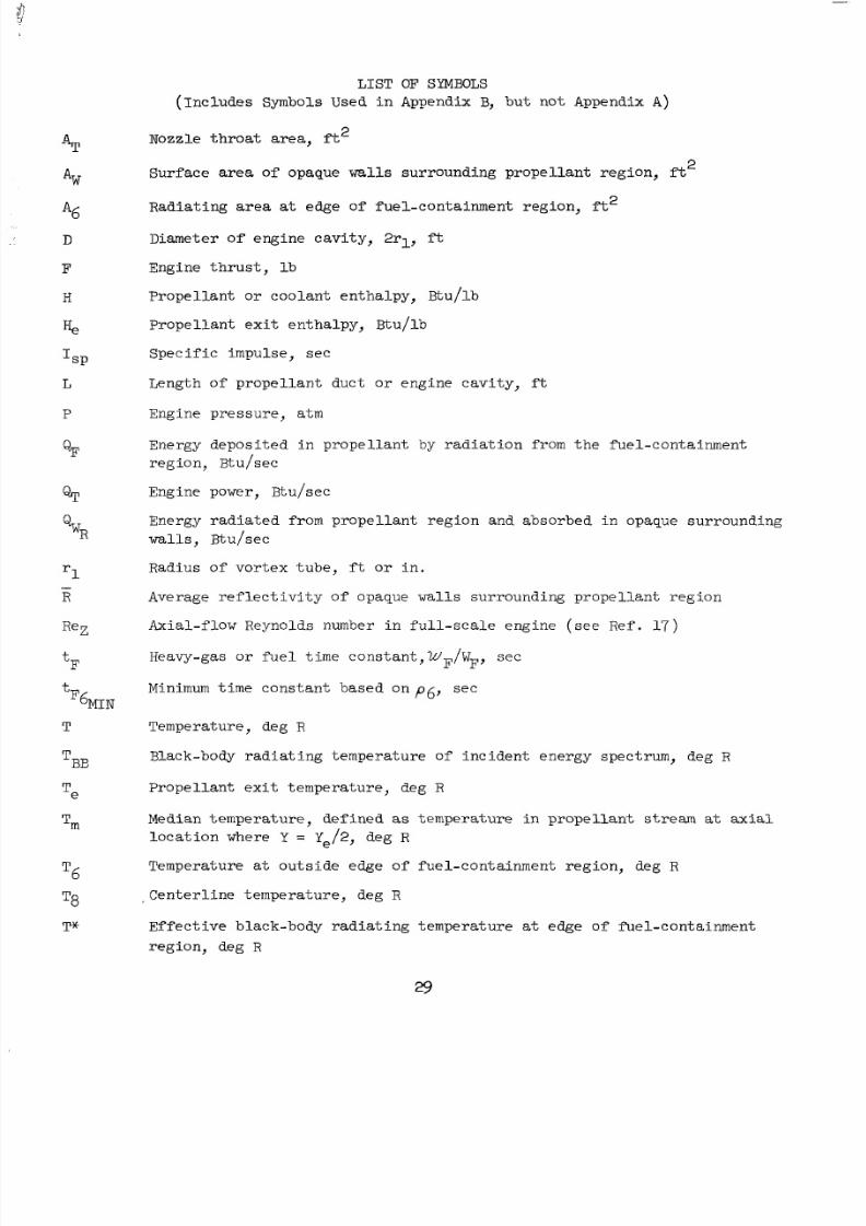
8/2/2019 Nasa Report on Gas Core Nuclear Engines
http://slidepdf.com/reader/full/nasa-report-on-gas-core-nuclear-engines 33/105
AT
AW
D
F
H
H,
ISP
L
P
'-R
ReZ
tF
F6MIN
T~~
t
T
Te
Tm
LIST
(Includes SymbolsUsed i n
Nozzle throat area, ft2
Surface area of opaque walls
OF SYMBOLS
Appendix B, bu t no t Appendix A )
sur roundingprope l l an t eg ion , f t
Radia t i ng area a t edge o f fue l -conta inmentregion, f t 2
Diameter of eng inecavi ty, 2rl , ft
Engine t h r u s t , b
Prope l l an t or coolantentha lpy,Btu/ lb
Prope l l an t e x i t entha lpy,Btu/ lb
Specific mpulse , ec
Lengthofprope l lantduc t or enginecavi ty , ft
Engine pressure , atm
Energy de po si te d n pro pe l la nt by ra di a t io n from thefue l -conta inment
region,Btu/sec
Engine power, Btu /sec
Energy rad ia te d f rom prop e l lant regio n andabsorb ed n opaque surrou nding
walls, Btu/sec
Radiusofvor tex ube , f t or i n .
Average re f l ec t i v i ty o f opaque walls surroundingprope l lantregion
Axial-flowReyn olds number in f u l l - s c a l ee n g i n e ( s e eR e f . 17)
Heavy-gas or fuel imeconstant ,WF/WF,sec
Minimum time cons tant based on p6 , sec
Temperature,deg R
Black-body radi at ing emper atur eof nc iden tene rgyspec t rum, deg R
P r o p e l l a n tex i t empe ra tu re , deg R
Median temperature,def ined as t empe ra tu re n p r o p e l l a n t stream a t a x i al
loc a t io n where Y = Ye/2, deg R
Temperature a t outs ideedgeof uel-con tainment egion, deg R
Centerl ine emperature ,deg R
Effec t ive b l ack-bodyrad i a t ing empera tu re a t edge of f 'uel-containment
region,deg R
29
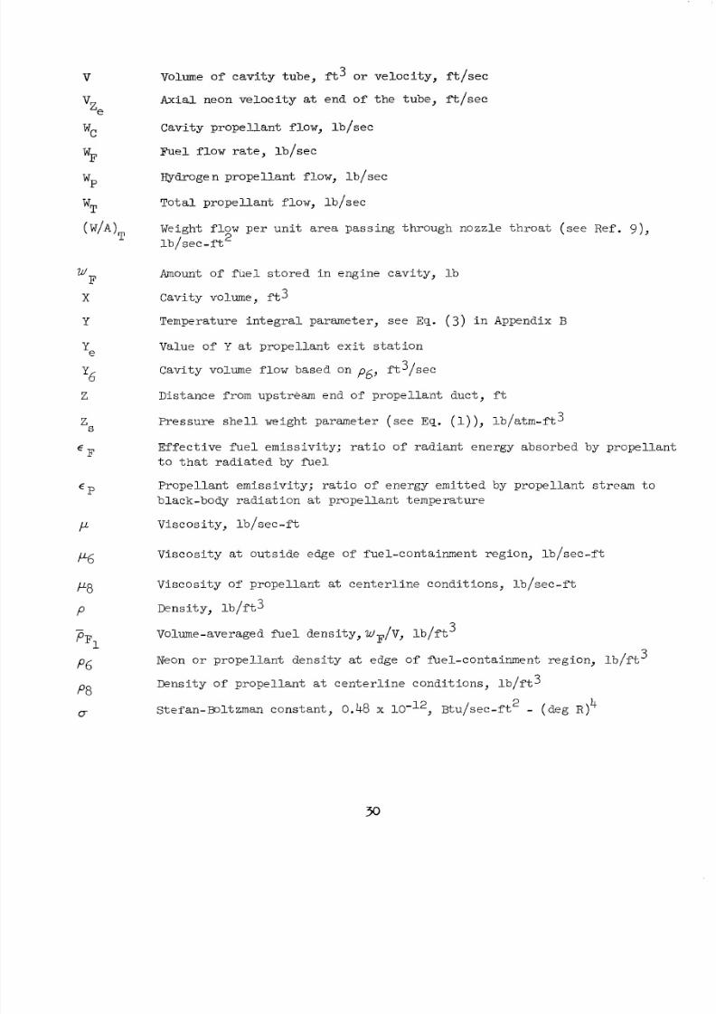
8/2/2019 Nasa Report on Gas Core Nuclear Engines
http://slidepdf.com/reader/full/nasa-report-on-gas-core-nuclear-engines 34/105
V
'e
wC
wF
wP
wT
(
W
X
Y
F
'e
'
Z
zS
€ F
€P
P
Volume ofc a v i t y u b e , f't3 or v e l o c i t y ,f t / s e c
Axial neon ve loc i ty a t end of the ube, f't/sec
Cavi typropel lan t low, b /sec
Fuel f low ra te , l b / sec
Hydrogen propellantf low, b / sec
To ta lp rope l l an t low, b / sec
Weight f l ow pe r un it area pass ing hroughnozzle h roa t( seeRef . 9),
l b / s e c - f t 2
Amount of f u e l s t o r e d n e n g i n e c a v i t y , b
Cavity volume, f t 3
Tempera ture n tegra lparameter , ee Eq. (3 ) i n Appendix B
Value of Y a t p r o p e l l a n t e x i t s t a t i o n
Cavity volume flow based on f 6 , f t 3 / s e c
Distance romupstreamend of prope l l an tduc t , f t
Pressu reshe l lwe igh tpa rame te r ( see E q . (l)), l b / a tm- f t3
Ef fec t ive fue l emiss iv i ty ; r a t io o f r ad ian t ene rgy abso rbed by p rope l l an t
t o t h a t r a d i a t e d by f i e 1
P r o p e l l a n te m i s s i v i t y ;r a t io o fe n e r g yemi t t ed by p rope l l an t s t r e a m o
b lack -bodyrad ia t ion a t prope l l an t empera tu re
V i s c o s i t y , b / s e c - f t
V i s c o s i t y a t outs ide edge of fue l - con ta inmen t eg ion , b / sec - f t
V i s c o s i t y of p r o p e l l a n t a t c e n t e r l i n e c o n d i t i o n s , b / s e c - f t
D e n s i t y , b / f t 3
Volume-averaged f u e l dens i ty , WF/V, l b / f t 3
Neon or p r o p e l l a n td e n s i t y a t edge ofPuel-conta inment eg ion , b / f t
Dens i tyo fp rope l l an t a t c e n t e r l i n e c o n d i t i o n s , b / f t 3
Stefan-Boltzmanonstant , 0.48 x Btu/sec- f t - (deg R ) 4
3
2
8/2/2019 Nasa Report on Gas Core Nuclear Engines
http://slidepdf.com/reader/full/nasa-report-on-gas-core-nuclear-engines 35/105
APPENDIX A
F I W - W O U N D PRESSURE VESSEL DESIGN STUDY
FOR NUCLEARLIGHT E!ULB E N G I N E
m: F. G. Siedow - Sen ior Designngineer, Motor Case &sign GroupC. H. Mart in - Group Head, Motor Case Design Group
Approvedby: D. A . North - Sect ionChief,MechanicalSystems&sign
R . A . Jankowski - Program Manager
UnitedTechnologyCenter;Division of Un ited Airc ra f tCorpora t ion
Abst rac t
A des igns tudy was conducted t o de te rmine he optimum con f ig ur a t io n fo r a
f i l a m e n t - w o u n dgla s sp r e s s u r es h e l l o r a nuc l ea r ocke teng ine . Also i nves t i ga t ed
were th e va ri ou s problem ar eas ass oc iate d wi th he de sig n of components , materials ,
fa br i ca t i o n methods, and s t ruc tu ra l degr ada t i o n due t o t he an t i c i pa t ed env i ronm ent .
Des ign Spec i f ica t i ons (Fu rnis hed by UARL)
I t i s d e s i r a b l e o o b t a i n p r e l i m i n a r y estimates o f h e s t r u c t u r a l w e i g h t of
f o u rd i f f e r e n tp r e s s u r es h e l lde si gn s which ar e shown inF i g . 18. Configura t ions
A and B a r e s p h e r i c a l a n d e n c l o s e a volume which i s c o n s i d e r a b l y l a r g e r t h a n t h e
a ct u a l volume of hemajorenginecomponents .Configurat ions C an d D have a sma l l e r
envelope which i s s l i g h t l y l a r ge r t ha n t he ma j or components o f a prel iminary con-
f i g u r a t i o nc o n s i d e r e d a t UARL. A l l f o u rconf igura t i ons have a 0.5 f t - d i a h o l e n
the forw ard end which w i l l con tain he duc t hro ugh which th e hydrogen i s c a r r i e d
i n t o h ee n g i n e .C o n f i g u r a t i o n s A and C have a 1 f t - d i a h o l e n h e a f t endof he
p r e s s u r ev e s s e l op e r m i t n s e r t i o no f a s ing l eexhaus tnozz l e .Conf igura t i ons B
and D h a v e s e v e n h o l e s n h e a f t en dof hepre s surevesse l , each ho lehav ing a
diameterof 0 .4 ft, f o r n s e r t i o n o f s e v e ns e p a r a t e n o z z l e s f o r s e v e n s e p a r a t e
u n i t c a v i t i e s . Each o f h econf igur a t ion s would req ui r e a f langeof some ki ndnear
th ep o i n to f m a x i m u m diameter t o p e r m i t a c c e s s o h e n s i d e o f h e p r e s s u r e v e s s e l .
The d e s i g n c a v i t y p r e s s u r e f o r a l l c o n f i g u r a t i o n s i s 500 a t m ( 7350 p s i ) .
The neutronand gamma f lu x app ro ach ing he pre ssu re she l l i s approximately
100 Btu/sec-f t2 . If t h edens i t yo f h ep r e s s u r e vesse l i s t aken as 120 lb/ f t3 ,
t h ea t t e n u a t i o nc o e f f i c i e n t i s 1.8 ft-l. Thus t h ee n e r g yd e p o s i t i o np e runit volume
31
8/2/2019 Nasa Report on Gas Core Nuclear Engines
http://slidepdf.com/reader/full/nasa-report-on-gas-core-nuclear-engines 36/105
due to abso rp t io n o f neu t ron and gamma ene rgy nea r the in s i de su r f ace o f the p re s -
s u r e shel l wouldbe 180 %tu/sec-f t3 .Thisheatdeposit ion ra te would decrease by a
f a c t o r o f l / e for eve ry 0.55 f t o f d i s t a n c e h r o u g h h e p r e s s u r e s h e l l .
It i s necesss :-y t o condu ct he hea t depo si te d wi t h in he volume of he pres sure
s h e l l t o a c o o l a c t f l u i d l o c a t e d o n one s ide or t h e o t h e r o f t h e p r e s s u r e s h e l l .
T h i s c o n d u c t i o n o f h e a t r e q u i r e s h a t h e e m p e r a t u r e n h e c e n t e r o f h e s h e l l
t h i c k n e s s be g r e a t e r h a n h e e m p e r a t u r e on e i t h e r s i d e . This empera tu red i f -
f e r ence i s a f u n c t i o no f h e h i c k n e s so f h ep r e s s u r es h e l l .P r e l i m i n a r yc a l c u l a -
t i o n s were made on t h e b a s i s t h a t t h e p r e s s u r e s h e l l was made from a se r i e s of
i n d i v i d u a ls h e l l s ,w i t h h e f i r s t s h e l lh a v i n g a t h i c k n e s s of 2.0 i n . I n a s h e l l
having a t h i cknesso f2 .0 n . , he empera tu re a t t h e c e n t e r of t h e s h e l l t h i c k n e s s
would be approximately 100 R h i g h e r h a n h e e m p e r a t u r e a t t h e edge f o r a thermal
c o n d u c t i v i t y of Btu/sec- f t -deg R. If t heempera tu re a t t h e edge i s t aken
as 400 R, t h ecen te r l i ne emp era t u re wouldbe500 R. The al lo wab le hick nes s of
e a c h s u c c e e d i n g s h e l l for t h e same a l lowab le empe ra ture d i f f e r ence would be
g r e a t e r h a n n h e f i r s t s h e l l .
The ma j o r po r t ion o f the ene rgy depo s i t e d in the she l l wouldbe emovedby
hydrogenp rope l l an tpass inga long he n s ideo f he nne rsh el l. The ene rgy removed
from the ou te r po r t ion o f he inner s h e l l a nd ro mboth s ides of anysucceeding
she l l s wou ldbe de po si te d in hydrogenwhichwould l a t e r be u s e d f o r t r a n s p i r a t i o n
coo l ingo f henoz zle . The pres sure betweeneach ayer of p r e s s u r e shell wouldbe
c o n t r o l l e d s o as t o p r o p e r l y d i v i d e h e bu rs t i ng oa d on ea ch aye r . The ou termost
p r e s s u r es h e l l w o u l dbecooledalmostentirely rom i t s i n s i d es u r f a c e . I t i s
recommended th a t th e in i t i a l d e s ig n employ two p r e s s u r es h e l l s ,a l th oug h more ar e
pe rmiss ib le .
The f as t n e u t r o n f l u x n c i d e n t on t h e i n n e r s h e l l i s approximately 2 x
neutrons/cm2-sec. The burn ing ime n a s i n g l e l i g h t i s approximately lo3 s e c .T h e r e f o r e , h e o t a l f a s t neutrond os e t o h e n s i d e s u r f a c e o f t h e p r e s s u r e s h e l l
would be approx imat ely 2 x 10¹⁷ neutron/cm 2 .
Summary and Co nc lu sion s
An ob lat e-o va loi dshape , which gen era l ly fo l l ows he mot or con tour and employs
a s i n g l e c e n t r a l l y o c a t e d n o z z l e o p e n i n g , was employed i n a l l s t u d i e s u n l e s s
o t h e r w i s espe ci f ie d . The de s ig nc o n f i g u r a t i o ns e l e c t e d i s shown i n F i g . 19 and was
d e r i ve d from t h e s p e c i f i c a t i o n s g i v e n n F i g . 1 8 c .
A weightandcost summary o f he fou r con f igu r a t io ns g ive n n F ig . 18 i s pre-s e n t e d nT a b l e X I X . The weight o f t h er e f e r e n c e d e s i g n s e l e c t e df o rd i s c u s s i o n n
t h i s Appendix i s 18,965 l b . The e s t ima tedu n i tc o s to f h es e l e c t e dd e s i g n ,n o t
including development cost , i s approximately $3OO,OOO. (No te tha t hec o n f i g u r a t i o n
d i scussed i n t h e t e x t i s derived from Fig. 18d r a t h e r h a n 1 8 c . )
32
8/2/2019 Nasa Report on Gas Core Nuclear Engines
http://slidepdf.com/reader/full/nasa-report-on-gas-core-nuclear-engines 37/105
The i d e a l i z e d g l a s s s t r es s l eve l chosen i s 400,000 p s i , a n d h e r e s u l t i n g
d e s i g n a l l o w a b l e s t r e s s e v e l s a r e 251,000 p s i for t h e h e l i c a l f i b e r s a n d
270,000 p s i f o r t h e hoop f i b e r . The i n f l u e n c eo fg l a s ss t ren gth on weightandcost
i s shown in F ig . 20 . Thi sda tahasbeenadapted from UTC expe r i encega ined n
des ign and fabr i ca t i on o f f i l ament -wound s t ruc tu re s f rom 50 i n . t o 158 i n . d i a .
Table X I X i l l u s t r a t e s t h a t o v e r a l l weight i s n o t o v e r l y s e n s i t i v e o h e n c l u -
s i o n o f m u l t i p l e a f t endopenings.This i s due t o h e a c t h a t h eo p e n i n g i z e s
a r e small compared t o hec a s ed i a m e t e r a n d wall t h i ckness .
F igure 21 i l l u s t r a t e s t h e i n f l u e n c e o f th er m alenvi ronmentsonf iberglas
l amina t eprope r t i e s . A t t he empera tu re san t i c ipa t ed , no s t r eng th educ t i onh as
been considered.
DesignAssumptionsand Limitat ions
The d es i gn sp ec i f ica t ion s employed in th i s s t u d y were provided by Uni ted
Ai rc ra f tResea rchLa bo ra to ri es (UARL) (s eep r e c e d i n g e c t i o n ) .S i n c e e v e r a l
aspec tsof hedes ignstu dy were no twi th in c u r r e n t n d u s t r ys t a t e -o f - t he -a r t , it
became n ece ssa ry o make ce r ta in assu mpt i ons and s im pl i f ic a t io ns n ord er o co mp le te
th es tud y. The sp ec i f i ca t io ns assumed in he s tudy havebeen ummarizedbelowand
a re d i scussed n g rea t e r de t a i l n subsequ en t pa ragraph s .
(1) A des ignul t imatepre s sureof 7350 p si .
( 2 ) mdrogenpre s surec a n be c o n t r o l l e d o 3675 p s i between th e two pressur e
s h e l l s .
( 3 ) The optimum dome contours shown inF i g . 19 canbe mployed.
( 4 ) The temperature a t t h e wall s u r f a c e will be maintained a t 400 R and t ha t
a 10 0 R t e m p e r a t u r e r i s e w i l l occur midway thro ugh the 2- in . - th ic k glas s
re s in compos i t e wall.
( 5 ) M a t e r i a lp rope r t i e s havenotbeendegraded for f a t i g u e or r a d i a t i o n
e f f e c t s .
(6 ) J o i n tm a t e r i a lpr op er t ies assumed fo r he b a s i c c o n f i g u r a t i o n a r e
a t t a i n a b l e i n a case o f t h i s s i z e .
( 7 ) F a s t e n e r sa r eo b t a i n a b l e n h e 300 KSI s t r e n g t h e v e lw i t hs u y f i c i e n t
t oughness t o wi th s t and oad i ng a t t h e l ower emperatu re imi t so f he
hydrogen coolant .
( 8 ) Technica lp rob l emsassoc ia ted wi thfabr ica t ion could be solved g iven suf-
f i c i e n t t i m e f o r s tudy.
33
8/2/2019 Nasa Report on Gas Core Nuclear Engines
http://slidepdf.com/reader/full/nasa-report-on-gas-core-nuclear-engines 38/105
(9) NO t r a n s i e n t c o n d i t i o n s of pre s sureand empera ture wereassumed during
s t a r t u p or shutdown.
-s ignConsidera t ions
The s u c c e s s f i l a p p l i c a t i o n o f g l a s s f i l a m e n t r e s i n c o m p o si t e m a t er i al s f o r
p r e s s u r e v e s s e l s r e q u i r e s p e c i a l c o n s i d e r a t i o n b e g i v e n t h e i n f l u e n c e of c a s e
geometryan d t o t a l e n v i r o n m e n t o n t h e u l t i m a te s t r e n g t h c a p a b i li t y o f t h e m a t e r i al s .
The ex te n t to which these cons idera t ions nf luence heproposeddes ign a redis -
c u s s e d b r i e f l y i n t h e f o l l o w i n g s e c t i o n s .
The st r eng th of a s t r a n d ( a bundleofcont inuousfi laments ga thered oge ther
i n t h e f o rm i ngopera t ion) i s g e n e r a l l y e s s h a n h e p u r e f i l a m e n t s t r e n g t h by a
fa c to r of 20 t o 30 per cen t . The st ren gthof a st ra nd Composite t h a t i s a c t i n g as
pa r t o f a f i lament-wound st ructure i s g e n e r a l l y 25 t o 30 pe rcen t less t h a n t h a t
determined from a s t r a n d e s t . UTC des ignexpe r i ence nd i ca t e s ha t a pures t rand
s t rengthof 5OO,OOO p s ican be cons i s t en t l yob t a inedwi th S-gOl gla s s .T h i s
s t rength mustbe fu r the r r educed by va r ious fac to r s d i scussed n fo l l owing sec t i ons .
CaseGeometry
Filament-wound pre ssu re ves sel s wit h small l eng th - to -d i ame te r r a t i os , equa l
bossopeningsizes,and small boss- to-casediameters are most effic ient when using
a h el ic a l winding pa t t e r n employing a geodesic-ovaloid dome contour (seeRef . 28).
Accordingly, a h e l i c a l winding pa t t e rn ha s been chosen and modif i ed s l i gh t ly to
account fo r t he un equ a l endopeningdiametersand non-optimum win din gangle
re su l t in g f rom the uneq ua l dome s iz es .
Chamber wall t h i c k n e s s n f l u e n c e s h e r e a l i z a b l e f i l a m e n t s t r e n g t h as a
r e s u l t o f h e h i g h e r s tr e s s e s d e v e l o p e d a t t h e n n e r s u r f a c e h a n a t t h e o u t e r
sur face due t o t h e t h i ck se c t i on an d a l s o by mandre l sh r inkage dur ing fabr i ca ti on
which al low s he nne rwind ings o e l axdur ingwind ingunde rpre t ens ion .Thi s
e f fec t can becompensated fo r i n e i t h e r o f two ways: (1) y app l i ca t i on of Lame Is
equa t ions o de te r mine he amount ofwinding ens ionrequi red oproduceequa l
s t r es s ineachf i l ament aye r h roughout he wall; or, ( 2 ) by appl ica t iono f a
s t reng th reduc t i on fac to r o he a l l owable s t r and s t r eng th o account fo r he
r e s u l t i n g d e g r a d a t i o n .
P a s texpe r i ence has nd i ca t ed ha t he re i s some loss i n s t r e n g t h w i t h
increas ingdiameter . The l o s s i ne f f i c i e n c yh a s been a t t r i b u t e d o : (1) h e
inc rea sed h i ckness i f pressure emainscons tant ; ( 2 ) t h e n c r e a s e d probab i l i t y o fthepre sence of s t ru c t ur a l de fe c t s due to t h e added volume of mater ia l nvolved;
and (3 ) l o a d s a r e t r a n s f e r r e d l e s s e f f i c i e n t l y between l a y e r s of f i b e r s i n v e r y
th i ck amina t e s . Any s t r e s se s a re ma ni f e s t e d i n t he fo rmof sh ea r s t r e s s between
l aye rs .Th i se f fec th a sbee n compensated f o r byappropr i a t ely educ ing hedes ign
8/2/2019 Nasa Report on Gas Core Nuclear Engines
http://slidepdf.com/reader/full/nasa-report-on-gas-core-nuclear-engines 39/105
a l l owable s t r and s t r eng th .
When a s e c t i o n or hole has been cut out of a dome, t h e membrane lo a d must be
t ransfe rreda longano the rpa thsurr oun ding he removed ma te ria l . To p r o v i d e h i s
a d d e d o a dca r ry ing capac i t y , r e in forc ing media, g l a s s c lo th , ape , e t c . mustbe
employedbetween f i l a men t aye rsd u r i n gf a b r i c a t i o n . As a resul t of he above, a
s t r e n g t h r e d u c t i o n f a c t o r i s g e n e r a l l y a p p l i e d t o t h e d e s i g n a l l o w a b l e s t r a n d
s t r e n g t h t o a c c o u n t f o r t h i s e f f e c t .
To o b t a i n a ful l -d iameterpen ingn a f i l ament -woundressureessel ,hev e s s e l must f i r s t be wound integrallya n d h e nsec t i oned . Thi s requ i re s ha t he
jo in t a r ea be r e i n f or ce d t o compensate fo r t he red i s t r i b u t i on of fo rce s be tween he
f i l ament san d he oi ni ng medium, bo lt s,p i n s ,e t c . na d d i t i o n , o c a ld i s c o n t i n u -
imposedon ad j acen t f i l ament s .
i t i e s e s u l t i n g from t h ed i f f e r e n t e c t i o n i z e s e s u l t na d d i t i o n a l o a d sb e i n g
Environmental Factors
Eleva ted empera tureaffectsf i l ament -woundcomposi tesessent ia l ly as showni nF i g . 21 . S i n c e h e e m p e r a t u r e n h e i b e r g l a s wall i n h i s a p p l i c a t i o n i s
e s t i m a t e d t o be 500 R a t t h e c e n t e r an d 400 R a t t he ou t s ide su r face , no s t r e ng t h
degrada t ionhasbeen assumed for t h i sde si gn . The above th er ma lgrad i en t s w i l l
r e s u l t i n a thermal s t ress of approximate ly 560 p s i i n t h e w a l l which i s
i n s i g n i f i c a n t .
The exposure o f f i l ament -woun d s t ruc tu re s o l ow empera tu re s a s soc i a ted wi th
l i qu id hydrogen du r in gs t a r t u p i s not deemed t o be a problem (seeRef . 29). Resu l t s
of a t e s t program conducted by Stanford Linear Acce le ra tor Cente r , S tanford
Univers i ty ,S t anford ,Cal i fornia , onUTC-prepared sp eci men s nd ica ted ha tcer ta in
c o m p o s i t e s a r e e n t i r e l y s u i t a b l e for use a t 50 R i n p r e s s u r e v e s s e l a p p l i c a t i o n s .
(seeRef . 30). F a t i g u e e s t s a t lo7 cyc les and 9000 p s if l e x u r a la n d 300 p s is h e a r
s t re ss showed th a t th e f il ament-wound s t ru c t ur e hadno t l os t i t s o r i g i n a l p r o p e r t i e s .
Gamma r a y and p a r t i c u l a t e r a d i a t i o n , e s p e c i a l l y t h a t above 1/2-1MEV energy,
are p o t e n t i a l l ydan ger ou s o ibe rgl as ami na t es . The epoxy matrix, beingan
org ani c compound, ca n be at ta ck ed an d de gr ad ed n se ve ra l ways by bo th gamma ray s
andneutrons. No a t tempthasbe en made to e s t i m a t e h e n f l u e n c eo frad i a t i on on
th edes ign a l l owableg l a s ss t reng th .
G l a s s - f i b e r r e i n f o r c e d p l a s t i c s a r e s u s c e p t i b l e t o d e g r a d a t i o n i n a vacuum
environment as a r e s u l t of the weakeningof ongchainpolymeric compounds.
=grada t ion i s a func t i on o f empe ra tu re and time, and i s evidenced by a l o s s i nweightandassociatedchanges inmechan i ca lprop er t ies . The re su l t s o f R e f . 31
i n d i c a t e h a t , a t e l eva t ed empera tu re n a vacuum, a 5 t o 10 pe rcen t reduc t i on n
s t rengthperyea rcan be expec ted.Accord ing ly , hemis s iondura t ion, naddi t ion
35
8/2/2019 Nasa Report on Gas Core Nuclear Engines
http://slidepdf.com/reader/full/nasa-report-on-gas-core-nuclear-engines 40/105
t o a c t u a l o p e r a t i n g d u r a t i o n , must b e c o n s i d e r e d n c o n s i d e r i n g g l a s s - r e s i n
compos i t edes igns o rspaceapp l i ca t ion .
F i n a l b u r s t p r e s s u r e f o r a n y chamber i s s i g n i f i c a n t l y a f f e c t e d by t h e number o f
p r i o r p r e s s u r i z a t i o n c y c l e s a n d t h e i r d u r a t i o n a n d t h e r a t e o f p r e s s u r i z a t i o n ; h e
f a s t e r ra tes p r o v i d i n gh i g h e rb u r s tv a l u e s .A c c o r d i n g l y , oa s s u re he maximum
r e l i a b i l i t y w i t h a minimum of s t r uc tur a l de gra da t io n , it i s UTC's p r a c t i c e t o employ
a minimum fa c t or o f s af e t y of 1.25 t imes p roo f p r e ssu re and t o p ro o f t e s t from 8 t o
10 percen tab ov e he maximum ex pe ct edope ra t ingp ressu re . This providesadequate
marg in for a 5 percen tdeg rada t iondu r ingp roo f e s t ingandassu ressuccess fu l
o p e r a t i o n a t t hesubsequen tope ra t ingp ressu re .
Descr ip t ion of Se lec ted Design
The desig n employed i n most of hes t u d i e s i s shown in F i g . 19. The oblateshape
i s term ina ted by modif ied geode sic sotens oid domes which a re t h e most e f f i c i e n t
d e s i g nat t a in ab l e . The s ing leendopening s were ch os en f o r h i ss t u d yfor manu-
f a c t u r i n gs i m p l i c i t ya n dw e i g h tsav ings . The weigh t ncreas e ormu l t ip l eopen ings
wouldbe only a few percen t ,bu tcos t smight be 8 t o 10 percen th ighe r .Mul t ip leo p e n i n g s r e q u i r e h e a d d i t i o n o f s p e c i a l r e i n f o r c e m e n t s s u r r o u n d i n g e a c h o p e ni n g o
t r a n s f e r h e o a d s a r o u n d h e o p e n i n g , n a d d i t i o n o h e e x t r a f i t t i n g s r e q u i r e d .
Weights a re p res en te d n Tab le XIX for a l l four con f igu ra t i ons shown i n
F i g . 18. There a re s e v e r a l e a s o n s o r h ew e i g h t n c r e a s e o r h es p h e r i c a ls h e l l
conf igura t ion . The f i r s t i s t ha t heg l a s sa n d e s i nw e i g h t ,a n d h e r e f o r ew e i g h t
performance, of a pu re ve ss el of optimum i so ten so id de sig n i s d i r e c t l y r e l a t e d t o
th een cl os ed volume. Si nc e he volume of t h es p h e r e i s g r e a t e r h a n h a t f o r h e
ob la teshape , hebas icshe l lwe igh t s w i l l a l s ob eg r e a t e r . na d d i t i o n , h eo b l a t e
shape w as chosenover hespher ica lshapebecause a t ruef i lament-woundspherecannot
be made becauseofmanufac tur ingconsidera t ions . I t i s anapp rox ima t iona r r ived a twi th a success ionofwindings ,each a t anang leand h icknessco r r e spond ing o i t s
s t r e s s a t t h eh i g h e s tpo in t. Each winding, th en , i s u n d e r - s t r e s s e d a t a l l o t h e r
p o i n t s , a n d h e v e s s e l as a whole may be 20 t o 30 percen theav ie r hananova lo ida l
v e s s e l .
A f u r t h e rd i s a d v a n t a g eo f h e s p h e r i c a lc a s e i s theaddedweight o f t h e f u l l -
diam eter o in t . The jo in tw e i g h t i s increasedover hepr imarydesignbecauseof
t h e g r e a t e r r a d i u s , as t h e a r g e r r a d i u s p r o d u c e s a r g e r o i n t o a d sa n d h eg r e a t e r
r ad iu sco nt ai ns more volume o fs t r u c t u r a l material i n h e o i n t . The c o s to f h e
s p h e r i c a l c a s e i s g r e a t e r due t o t h e a d d e d f a b r i c a t i o n d i f f i c u lt i e s c a u s e d by t h e
d i f fe ren t win ding pa t t e rns and here fore machine se tupsrequireddur ingwinding .
End Domes
The end domes are g e o d e s i c s o t e n s o i d s h a p e s ,m o d i f i e ds l igh t ly on th e a f t end
t o a l l o w for t h e n c l u s i o n o f o i n t b u i l d u p s , a n d on t h e f o r w a r d e n d o a l l o w f o r
8/2/2019 Nasa Report on Gas Core Nuclear Engines
http://slidepdf.com/reader/full/nasa-report-on-gas-core-nuclear-engines 41/105
mismatchesbetween t h e dome an dcon ica lca se , non-optimum wi ndi ngangle,and smaller
forwardpolaropening. The a f t domes will be wound a t a nearly optimum angle
( 7 0 ) andaveragecon to ur t o s u i t t h e s h e l l a n d p o l a r f i t t i n g diameters.
The forward domes are for ce d by casegeometry t o be wound a t a much higher-than-opt imw angle ( loo) , and w i l l havemo di fie d COntOUrS t o f i t t h i s C o n d i t i o n ,
t h e t r a n s i t i o n from t h e c o n i c a l c a s e wall, a n d t h e Smal l P o l a r f i t t i n g .
Conical Sect ion
The cen te r sec t ion o f he ves se l i s c o n i c a l n shape , ape r ing from 60 i n .
i n s i d e r a d i u s on t h e a f t e nd t o 34.4 i n . i n s i d e r a d i u s on t h efo rwardendwi th a
84 i n . o n gc o n i c a lsec t ion . The ou te rs h e l l a f t i n s i d e a d i u s (65.6 i n . ) i s
s i z e d t o c l e a r t h e i n s i d e s h e l l j o i n t b u i l d u p a n d t a p e r s down t o c l e a r t h e i n n e r
s h e l l a t t he fo rward end (37.4 i n . ) . Thisproduces a taperedgapbetween he
s h e l l s as t h e o u t e r s h e l l h a s a h i g h e r c o n e a n g l e h a n h e n n e r s h e l l .
The windingangle a t t h e a f t endmatches he a f t dome, inc reas ing owar d he
forwardend as t h ed i a m e t e rdec rease s . The h e l i c a l wind ing h ickness nc reasestoward heforwardend ,and he hoopwinding hickness i s t a pe re d to compensate
f o r h e s e two e f f e c t s ok e e pweight down.The t o t a l w a l l t h i c k n e s s i s 2.108 i n .
a f t and 2.016 n . fwd f o r t h e i n n e r s h e l l a n d 2.308 i n . a f t and 2.216 in . fwd for
t h e o u t e r s h e l l .
The designa l l o w a b l eu l t i m a t eg l a s s s t r e s s i s 251,000 p s i f o r t h e h e l i c a l
windingsand 270,000 f o r h e hoops. The maximum h e l i c a l s t r e s s ( t h e o r e t i c a l ) i s
n e a r h e o i n tand he hoop s t r e s s i s unifor m. The ca se i s designed s o t h a te a c h
she l l w i th s t a nds ha l f he p re ssu re oad wi th he hyd rogen coo lan t oca ted be tween
t h e s h e l l s a t h a l f t h e chamber . p ressure .
The res in co nte n t i s 24 percen t b w which gives a l amina tedens i tyo f
0.0705 l b / i n . 3.
J o i n t s
The jo i n t des ign was d i c t a t e d by t h e v e r y h i g h a x i a l l o a d s p r e s e n t
(117,500 b / i n . ) . This oad i s near or above the oa d /d i ame te r r a t i o a t which
f i b e r g l a s j o i n t s become d i f f i c u l t b e c a u s e o f t h e low b e a r i n g - s h e a r t o t e n s i l e
s t r e n g t h a t i o . If small b o l t s are u s e d , h eb e a r i n g , h e a r ,a ndb o l t s t resses
are t o o h i g h , a n d w i t h a r g e b o l t s h e e n s i l e a n d s h e a r s t r e s s between th e bo l t s
i s t o o h i g h .
The double-rowbol ted langeconceptal low s enough bea ring ,shea r ,and n te r -
b o l t t e n s i l e area with a modera te ly h ick sec t ion , and s t i l l allows enough bolt
t e n s i l e area by v i r tu r e o f h e d o u b l e row o f b o l t s . B o l t s are spacedevery 4 .2 i n .
37
8/2/2019 Nasa Report on Gas Core Nuclear Engines
http://slidepdf.com/reader/full/nasa-report-on-gas-core-nuclear-engines 42/105
average,which means ev er y two b o l t s s h a r e 494,000 l b , or 247,000 l b p e r b o l t . The
b o l t s are 1 .125 - in . -d ia s tuds made from a material having 287,000 p s i min t e n s i l e
y i e l d s t r e n g t h .
T h e f i b e r g l a s s t re s s v a l u e s are: bea r ing - 54,200 psi,s h e a r - 17,850 p s i ,
i n t e r l a m i n a rs h e a r - about 3800 p s i , and i n t e r - b o l t e n s i l e - about 34,200 psi.
These are a l l a t t h e u p p e r limit of UTC's p r e s e n t f i b e r g l a s o i n t e c h n o l o g y , a n d
some developmentwouldhave t o bedone t o v e r i f y and improve thesevalues . The
j o i n tp r o b l e m sc o u l db e a l l e v i a t e d , i f n e c e s s a r y ,b y h e us e o f h r e e or more
s e p a r a t e s h e l l s r a t h e r t h a n t h e two sh e l l s shown in F i g . 1 9 .
Usually , a d o u b l e - c l e v i s o i n t i s t h e most e f f i c i e n t b e c a u s e o f t h e g r e a t e r
r a t i o o f n t e r - p i n o p i n d i a d i m e n s i o n s .T h i s a l l o w s a g r e a t e r number of pins ,
r e d u c i n g h e i b e r g l a sb e a r i n g s t r e s s a n d h ep i na n d i n ks h e a rs t r e sses . Wi th
veryhigh oading , however, th e se c ti o ns become ve ry hi ck which i s e v i d e n t n h e
p resen tdesign shown i n Fig . 19. There are 90 2- in . -d iap insand 90 l i n k s f o r e a c h
s h e l l , a l l o f 3OO,OOO p s i s t e e l .
The f i be rg la s yoke th ic kness i s 3.17 i n . a n d h es t r e s s e sa r e :b e a r i n g -40,000 p s i ,s h e a r - 20,000 psi,a n d n t e r - p i n e n s i l e - 30,000 p s i . These valu es
are basedon U T C ' s p r e s e n t o i n t e c h n o l o g y f o r h i s y p e o f c o n s t r u c t i o n , a n d c a n
p robab ly be r a i sed 20 pe rcen t , - poss ib l y 30 percen t , a f t e r a s u i ta b le development
programaimed a t o p t i m i z i n g h i s o i n t d e s i g n .
The cl ev is oi ntd e s i g n ,a l t h o u g hh e a v i e r , i s probably he more fea s i b l e of
t h e two basedonpresent echnologybecauseof hereasonsg iv en i n t h e f i r s t
p a r a g r a p h .W e i g h t so f h ec a s ew i t h h ec l e v i s o i n t are g iven nTab le XIX.
P o l a r F i t t i n n s
P o l a r f i t t i n g s are made from 7075-T6aluminum, designed a t an ul t ima te s t r e s s
of 60,000 p s i , t o a l l o w a g e n e r o u s s a f e t y f a c t o r f o r p o s s i b l e h e a t i n g o s r a d i a t i o n
d e g r a d a t i o ne f f e c t s . The po la r f i t t i n g s are des igned so tha t he nne ra n do u t e r
f i t t i n gs nde x on ea ch o t he r o oc a t e he ou te r dome con cen t r i c o he nne r dome.
The i n n e r p o l a r f i t t i n g h a s p o r t s f o r h e p a s s a g e o f h e h y d r o g e n c o o l a n t from
between the s h e l l s . The o u t e rp o l a r i t t i n gh a s h r u - h o l e s s o t h a t i t can be
he l d in p la ce by t he bo l t s which ho ld on the nozz le or a f t c l o s u r e .
Materials and Fabr ica t ion Techniques
The g l a s s f i l a m e n t s c o n s i d e r e d n h i s d e s i g n s t u d y are Owens Corning S-9Ol Gs i z ef i l amen t s . Thesehavebee n shown by UTC and many otherc a s ewinde r s o be
th e h i g h e s ts t r e n g t ha n d most c o n s i s t e n t q u a l i t y f i l a m e n t s a v a i l a b l e .
The r e s i n s y s t e m u s e d f o r t h i s s t u d y i s Union Carbide FRL 2256 epoxy res in ,
8/2/2019 Nasa Report on Gas Core Nuclear Engines
http://slidepdf.com/reader/full/nasa-report-on-gas-core-nuclear-engines 43/105
o r o t h e r similar low-viscosity ypewithmetaphenylenediamine o r similar aromatic
polyamine hardener.Thissystemhasbe en shown by TJTC t o prod uc e t h e s t r o n g e s t
filament-wound vessels i n s i z e s from 2 i n . t o 14 f t i n d ia m et er .
The inner vesse l wouldbe wound us ing stand ard wind ing techni ques using a
h e l i c a l p a t t e r n and w e t wind ing (g la ss rov ings impregna ted wi th r e s in as t h e y arewound on to he ca se ) . The a f t dome wouldbe wound in t eg ra l wi th he for wa rd par t
of t h ec a s e o b e u to f f a f t e r cu re . o in tbu i ldup e in fo rcemen t would be dded
i n t h e j o i n t a r e a a n d wound i n b etw ee n t h e h e l i c a l w i n d i n g s . I n t h e c a s e of a
seven-nozzle onf igura t ion , e in forcements f o r the ozz les would also be added
between thehe l i ca l ay e r s . These r e in fo rcement s , o f s p e c i a lo r i e n t a t i o n , a re
pre-woundon a d i f f e r e n t m a n d r e l a n d k e p t r e f r i g e r a t e d u n t i l u s e .
After t he comple t ion o f wind ing , he case wouldbeB-stagedandgivenan
i n i t i a l c u r e a t approx imate ly 200 F. Then it wouldbe overcoatedwi thp la s t e rand
swept t o he p r o p e rc o n t o u rf o rw i n d i n go f h eo u t e rshe l l . The ou te r sh e l l would
t h e n be wound ove r he pla ste r ov erc oa tin g, €3-staged as above ,and hen he whole
mass c u r e d u l l y . n h eb o l t e d l a n g ev e r s i o n , h eca se would the n be cu t open
a t t h e f l a n g e n t e r f a c e , h e s h e l l s s e p a r a t e d f r o meachother ,and hen d r i l l e da n db a c ks p o t f a c e df o r h eb o l th o l e s .I n h ec l e v i s o i n tv e r s i o na l s o , h ep i n
kioleswould probably be d r i l l e d a f t e r t h e c a s e was c u t a p a r t .
Problem Areas
Conical Case
Filamentwindingofconicalcasesalwaysposesproblansbecau se of thechanging
windinga ng le from t h e a r g e o h e small end. The an gl e nc re as es down thecone ,
f o r c i n g h e small dome t o u s u a l l y be wound wit h oo h i g h a windingangle.This
e r r o rc a n be neu tra l iz ed by a l t e r i n g th e dome contours ,bu tc a n impose r e s t r i c t i o n s
on d iame t e r a t io s ,d i a m e t e r - t o - l e n g th a t i o s ,a l l o w a b l e w a l l s t r e s s ,e t c . Cases
of t h i s t y p e a r e p r o v e n e n t i r e l y by b u r s t t e s t s , and may tu r n ou t hea v ie r (or
l i g h t e r ) t h a n a n t i c i p a t e d .
I n a d d i t i o n , it i s v e r y d i f f i c u l t t o u s e hoop w in di ng s on c o n i c a l walls; UTC
has wound ca se s up to 15' h a l f a n g l e , b u t o n l y by s e m i - s t a g i n g t h e r e s i n u n t i l
very acky, henquicklywinding onehoop l a y e r . When done pr op erl y, hewindings
canb e made t o s t i c k b u t , i f n o t , h e n h e c a s e h a s o b e r e d e s i g n e d w i t h a lower
coneangle. The pr es en tdes ign wi th 15' and 16' h a l f angles) i s basedon he
p o s s i b i l i t y o f w i n d i n g on t h i s c on eangle ; however, th eforwardenddiameter
mu ld p robab ly have t o be i n c r e a s e d t o a l l o w a lower cone angle.
J o i n t
The pres en t o in t ( b o t hd e s i g n s ) i s a t t h e i m i t of known technology,and,
w h i l e b a s e d o n a c t u a l s t r e n g t h s r e a l i z e d i n t e s t s , may no t be f eas ib le n he s i ze
39
8/2/2019 Nasa Report on Gas Core Nuclear Engines
http://slidepdf.com/reader/full/nasa-report-on-gas-core-nuclear-engines 44/105
contempla ted .Thicksec t ions are n o ta l w a y ss t r o n g e r n r e l a t i o n o h e i r h i c k -
nessand may have t o be op era ted a t lower stresses t h a n a n t i c i p a t e d . A s n o te d i n
a preced ing sectio n, many of t h e j o i n t p ro bl em scouldbe a l l e v i a t e d by u s in g th r ee
or more r a th e r th an two p r e s s u r e s h e l l s .
In he pres en t des ign , he nec ess ary hoops may be mpossib le t o wind i n t h e
j o i n t area because of the h i g hs l o p e s on he b u i l d u p s ; n h a tc a s e ,h i g h - a n g l ehe l i ca l s would be u sed in the bu i l dup a r ea s which would r a i s e t h e w e i g h t s l i g h t l y .
Thermal
The l i n e r , f i b e r g l a s , a n d o i n t b o l t s m ig htbecooled t o 36 R d u r i n g h e
pausephases. While t h i sh a sbe en shown t o a c t u a l l y n c r e a s e h e pe rform anc eof
t h e f i b e r g l a s , it would e m b r i t t l e h e b o l t s a n d i n e r , p o s s i b l y o h e p o i n t o f
f a i l u r e i f full o p e r a t i n g p r e s s u r e i s r eachedbe fo re hese materials canheatup.
Sha rp he rma l g r ad ien t s du r ing s t a r tup may c r ea te he rma l s t resses u n t i l t h e r m a l
equ i l ib r ium i s reached .
R a d i a t i o n E f f e c t s
Gamma r a y a n d p a r t i c u l a t e r a d i a t i o n , e s p e c i a l l y t h a t above 1/2-1MEV energy,
are p o t e n t i a l l yd a n g e r o u s o a f ib erg las am ina te . The epoxy matr ix ,be ingan
org anic compound, can be at tac ke d an d de gra de d n severa l waysby bo th gamma r a y s
and neutrons.
Neu t rons ,especial ly above 1- 5 MEV energy ,displace wholeatoms or groupsof
atoms rom th emolecu le ,c r ea t ingb rokenmolecules whichcombine in d i f fe r e n t ways,
or are permanently erminateddepending on o th er c o n d i t i o n s . If small groupsof
atoms are b r o k e no f f , h e s ec a nb e i b e r a t e d as a gas, c r e a t i n gg a sbubble problems
i na d d i t i o n od e s t r o y i n g h ec h a i ns t r u c t u r eo f h ep o l y m e r .N e u t r o n sc a n , n
some cases,a l sop roducesecondaryrad ia t ions ,such as b e t a or a l p h a p a r t i c l e s ,
e t c . , which th en c.an prod uce sec ond ary radi atio n damage.
Gamma r a y sp r i m a r i l yp r o d u c ec h a i n s i s s i o n s ( ion iz in g) which produce sf r ee
r a d i c a l s w hi chcanrecombinewithothersuchradicals, or t e rmina te i f H atoms or
ions a re presen t .Th i schanges hemolecu la rwe igh tand ypeof he polymer,
thereforecomple te lychanging i t s p r o p e r t i e s . If pr imar i ly ecombinat ion o f t h e
f r e e r a d i c a l s o c c u r s , h e n h e polymer w i l l g r a d u a l l y n c r e a s e n s t r e n g t ha n d
modulus andd e c r e a s e ne l o n g a t i o n ,c r e a t i n g a b r i t t l e mater ia l . A s t h ep r o c e s s
con tinu es, he polymerwould s t a r t b r e a k i n g n t os u b - u n i t s( d e g r a d a t i o n )a n d
s t r e n g t ha n delo ng at i on would decrea sesharp ly . These ef fe c t s would a l l be reducedn o t i c e a b l y n h e f i b e r g l a s a m i n a t e , s i n c e h eg l a s sa c t s as a f i l l e r which eems
t o r e d u c e h e r a d i a t i o n damage e f f e c t s .
Varioussourceshavereporte d damage th re sh ol d l eve l s from 30 t o 1000 m a d
(megarads: 1Wad = 100 ergs/@-secab so rb ed ) of gamma or f a s t n e u t r o nr a d i a t i o n .
8/2/2019 Nasa Report on Gas Core Nuclear Engines
http://slidepdf.com/reader/full/nasa-report-on-gas-core-nuclear-engines 45/105
The genera l conse nsus
neutronsabove 50 MEV
f i b e r g l a s a m i n a t e s .
seems t o be,however,
will beg in t o deg rade
It i s p o s s i b l e a l s o h a t h e s e n t e n s e
t h a ta b o u t 600 m a do f gamma r a y s or
epoxies,and 1000 mad shoulddegrade
r a d i a t i o n s will damage t h e g la s s f i l a -
ments, es pe c i a l ly when they are under s t r es s . A b s o r p t i o no f a d i a t i o n i s propor-
t i o n a l t o d e n s i t y , a n d t h e g l a s s f i l a m e n t s would t h u s b e e x p e c t e d o a b s o r b h e
g r e a t e rp o r t i o n of t h er a d i a t i o ne n t e r i n g h e a m i n a t e .A l t h o u g hg l a s s i s no tc r y s t a l l i n e i n n a t u r e , it i s he ld oge the r by po la r , or associat ion bond-type,
a t t r a c t i o n betw een i t s atoms,and it i s p o s s i b l e h a t a su f f i c i en t number o f atom
" d i s l o c a t i o n s , " or d i s s o c i a t i o n s or f r e e e l e c t r o n s , c o u l d d e g ra d e h e s t re n g t h o f
t h e g l a s s .
If th e combined gamma and neu t ron f lux abso rbe d in the f ibe rg l as i s 180 Btu/sec-
ft w i t ha na t t e n u a t i o nf a c t o r o f 1/e eve ry 0 .55 f t , approximately 0.47 times
180Btu/sec-f t3 w i l l beabsorbed i n 5 i n .o f wall t h i c k n e s s . This co r r esponds t o
84 Btu/sec-f t3 , or 89 x 1010 e rg / sec - f t3 , o r 15.8 x lo7 erg/gm-sec, o r 1 . 5 8 Mradlsec
a b s o r b e d n h e wall. I n a 1000 se c un , h is means 1580 m a d o f a d i at i o n i s
absorbed,probably /3- l /2of which i s po te n t i a l l y damaging r ad i a t i on . If t h e s e
a r e h e c o r r e c t f i g u r e s , h e n h e r e i s a d e f i n i t e r a d i a t i o n e f f e c t o be c o ns i de r ed
i n d e s i g n i n g t h i s s h e l l o f f i b e r g l a s .
3
Iks ign Analys is
Glass S t r e s s
I n a c a s e o f h i s s i z e a n d o p e r a t i n g p r e s s u r e , h e r e are many factors which
a f f e c t h eu s a b l es t r e n g t h o f t h e g las s i l am en t s . An ind iv idua l ibe rh a s a
s t r eng tho fover 650 ,000 ps i ; in s t r and formabout500 ,000 ps i ; an d n a small
optimum pressure vesse l , about400 ,000ps i is r e a l i z a b l e ( 4 0 0 , 0 0 0 p s i i s termed
" i d e a l i z e d ' g l a s s s t r e s s i n F i g . 20). A f e w organ iza t ionshaveempi r i ca l lyde f inedt h ea l l o w a b l eg l a s s s t r e s s as a funct ionofvar iousparameters ,such as c a s e
diameter , wall t h i c k n e s s ,w i n d i n ga n g l e ,p o l a ro p e n i n gd i f f e r e n c e s ,e t c . n h i s
study, we w i l l use some design f a c t o r s a b u l a t e d n R e f .3 2 .
UTC ha s assumed a naveragecomposi te f i laments t rengthof 400,000 psi which
h a s b e e n m u l t i pl i e d by t h e f o l l o w i n g r e d u c t i o n f a c t o r s :
H e l i c a lac to r Hoop Fa ct or
Case diameter (120 i n . ) K = 0.85 0.90
Wall t h i c k n e s s / d i a m e t e r ( 2- 0.016)120
K = 0.73 0.75
P o l a r opening/diameter (18 = 0.15) K = 1.01
H e l i c a lu l t i m a t eg l a s s s t r e s s : 400,000 x 0.85 x 0.73 x 1.01 = 251,000 p s i
Hoop ultimateg l a s s s t r es s : 400,000 x 0.90 x 0.75 = 270,000 p s i
-120
-"
41
8/2/2019 Nasa Report on Gas Core Nuclear Engines
http://slidepdf.com/reader/full/nasa-report-on-gas-core-nuclear-engines 46/105
If r e s i n c o n t e n t i s assumed t o be 24 percen t bw, th e r e s i n bu lk f a c t o r , K, i s
1.68, and t h e c o m p o s i t e d e n s i t y i s 0.0705 l b / i n . 3.
Dome Design
Aft i n s i d e dome : t = PR - 3675 X 60
GQ 2c c o s 2 a 2 x 251,000 x 0.9825 = 0.447 n .GQ
t Q tG Q= 0.447x 1.68 = 0.750 n .
Aft o ut s id e dome : a = sin-' 7.9 = 6.8'"6.5
t =G Q
3675 x 65.6 = 0.487 i n .
2 . x 251,000 x 0.986
t, = 0.487x 1.68 = 0.818 n .
The dome contours w i l l be c a l c u l a t e d f o r h e a bo vewindinganglesand w a l l
th icknessandmodif ied t o i n c l u d e h e o i n t b u i l d u p s .
Fwd inside dome: a = s i n 7.9 x 60.5 = 10.2' a t dome-cone equator1"0.54.4
t = 0.447 x 60 = 0.604 n . ; t Q 0.604 x 1.68 = 1.015 i n .G Q 44,rc
Fwd outside dome: a = sin- ' 7.9 x 66.5 = 9.6'
66.547.4
t = 0.487 x 66.6 = 0.684 i n , ; t Q 0.684x 1.68 = 1.148 n .G, -
47.4
The contourso f he fwd domes w i l l have t o be compromised t o ac cou nt fo r he
ac tua l wind ing angle and he optimum a ngl e requ ired by the forward polar opening
s i z e . The t h e o r e t i c a l angles based on RE are :
I n s i d eh e l l : 01 = s i n 4.3 = 5.4 o u t s i d eh e l l : a = sin-' 4.3 = 5.1'1 0
m 48.4
42
8/2/2019 Nasa Report on Gas Core Nuclear Engines
http://slidepdf.com/reader/full/nasa-report-on-gas-core-nuclear-engines 47/105
Thus t h e b a s i c c o n t o u r o f h e n s i d e s h e l l will be a 6 O c o n t o u r a d j u s t e d n e a r
t h e p o l a r f i t t i n g f o r t h e smaller RE, and ne a r the equ a to r to match a 10’ contour
and 15’ c o n i c a l wall. The. ou ts ide con tou r wbe a 6’ c o n t o u r a d j u s t e d s i m i l a r l y
nea r he po le , and nea r he equa to r fo r a 9 O contour and he 1 6 O c o n i c a l wall.
Conica l Wall
A t t h e a f t t a n g e n t l i n e :
I n s i d e h e l l : cy = 7.5 , t = 0.447n., t, = 0.750Ga
0
t = PR (1- tan2:) = 3675 x 60 (1 0.1322) = 0.809 in .G€J - 2 270,000 2
TGe
t e = K t = 1.68 x 0.809 = 1.358 i n .G e
Outs ide he l l : a = 6 . 8 O , t G a = 0.487 n . , t, = 0.818 n .
t = 3675 x 65.6 (1 0.1192 2 = 0.887 i n .
Ge 270,000 2
t o = 1.68 x 0.887 = 1.490 n .
A t t h e forward “ t a n g e n t i n e ” :
I n s i d e h e l l : a = 10.2’, t = 0.604 i n . , to!= 1 .015n .Ga
t = PR (1 t a n a) 3675 x 4 4 . 4 (1 0.180 ) = 0.596 i n .2- -““e
270,000
t8 = K t = 1.68 x 0.596 = 1.001 n .
Ou ts ide he l l : cz = 9.6 , t = 0.684 i n . , t a = 1.148 i n .Ga
Ge0
t = 3675 x 47.4 (1 0.1691)= 0.636 i n .
Ge 270,000 2
t = 1.68 x 0.636 = 1.068 n .e
Bolted Flange Joint
Assume 1.125 i n . b o l t s n a double row wi th2 .2 n .spo tf aced iaand2 .0 n .
43
8/2/2019 Nasa Report on Gas Core Nuclear Engines
http://slidepdf.com/reader/full/nasa-report-on-gas-core-nuclear-engines 48/105
spacebetweenspotfaces;spacing = 2 .2 + 2.0 = 4 . 2 n .
Jo in t oad , n = PR 3675 x 64 = 117,500 l b / i n .- x
2
load /bo l t = 117,500 x 4 .2 = 247,000 l b
2
b o l t ut = F F 247,000"- r r m 2 = ~ / 4 1.053* = 284,000 psi
F i b e r g l a sb u i l d u ps t r e s s e s :
Bearing: u = F - 247,000 = 54,200 psiB
x/& Do' - Did) x / 4 (2.2' - 1. 25j2)
Bolt shear -ou t : a;, = F = 247,000 = 17,850 p s i
r D o t 2 .2 x 2.0
I n t e ro l te n s i l e : ut F/2 b o l t s
bu i ldup t x s p a c i n g - s p o tf ace a r e a s +s h e a r area x usu
-ct u
494,000x
4 .5 x 4 .2 - 2 ~ / 4 .P2 + 4.2 x 6 x 4500
36, ooo= 34,200 psi
In ter laminar hear ,assuming 5 h e l i c a l a y e r s : n = 5 )
A l t e r n a t e Clevis J o i n t
Assume the fo ll ow in g f i be rg la s yoke ult im ate s t resses :
Bearing cBV 40,000psi
I n t e r - b o l t t e n s i l e otu = 30,000 psi
Bolt shear -ou t csu= 20,000 psi
44
8/2/2019 Nasa Report on Gas Core Nuclear Engines
http://slidepdf.com/reader/full/nasa-report-on-gas-core-nuclear-engines 49/105
Use 90 p i n s ,2 . 0 n .d i a
t = PTR2 3675 x0- = 6 . 6 0n .2o k e s )
2-
Jutu (2rR - nd ) 0,0 00 (27762 - 180)
e = d cB- 1 = 20,000 - 1 = 1.00 i n . u s e . 0 n . )-2 %
-2 20,000
t l i n k =-/ l i n k = 518,000 = 0 . 7 2n .
u X w 300,000 x 2.4t u
l i n kh e a r : os = F = 518,000 = 133,000 ps i
2 t e .72 x 2 . 7 (usu M 1 8 0 , 0 0 0 p s i )
l i n ke a r i n g : u = F = 518,000 = 359,000 p s iB -t d 0.72 X 2 M 460,000 p s i )
P o l a r F i t t i n g s
&s i g n can be qu i ck lya p p r ox i m a te d by f i n d i n g t h e a x i a l l o a d / i n c h a t R
a ss um in g t h i s c o n c e n t r a t e d h a l f way up t h e f l a n g e fro m %, a n d s o l v i n g f o rV,
, c o n s i d e r i n g a s e c t i o no f h e l a n g e 1 n . n w i d t h .
t u
A f t p o l a r i t t i n g : Rv = 7.3; Rc = 9.68; Mat ' l = 7075 - T6 aluminum
u = 60,000t u
45
8/2/2019 Nasa Report on Gas Core Nuclear Engines
http://slidepdf.com/reader/full/nasa-report-on-gas-core-nuclear-engines 50/105
n = P% = 3675 x 7.3 = 13,500 l b / in .e2 2
x 13,500 x 1.19 =
=tu
t =
Fwd p o l a r fitting: = 4.0,
46
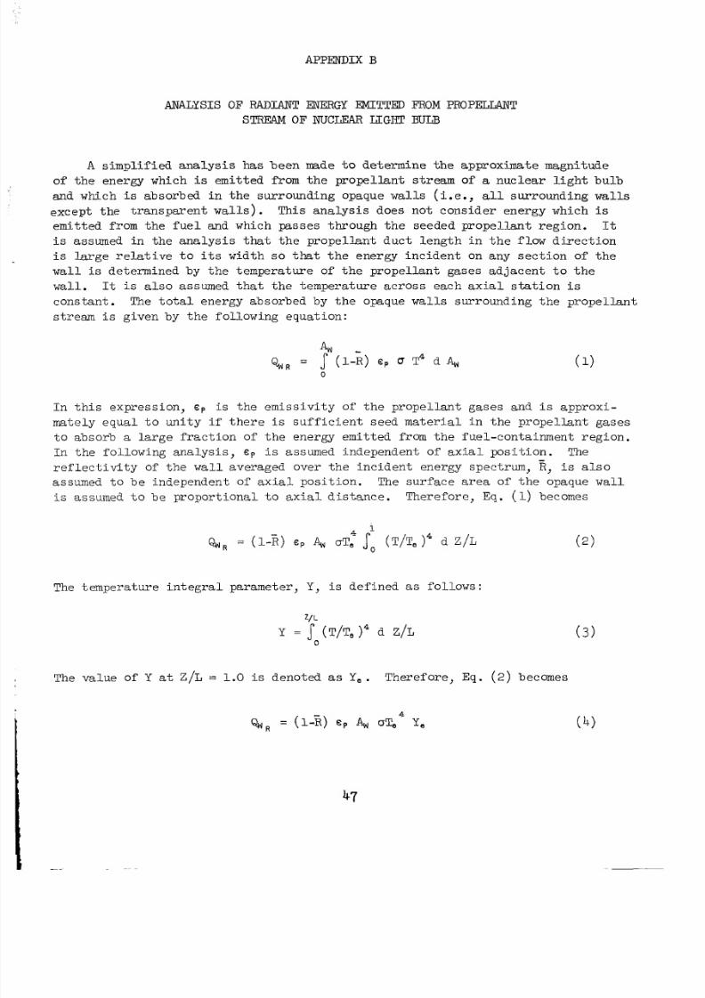
8/2/2019 Nasa Report on Gas Core Nuclear Engines
http://slidepdf.com/reader/full/nasa-report-on-gas-core-nuclear-engines 51/105
APPElYDIX B
ANALYSIS O F RADIANT ENERGY EMITTED FROM PROPELLANT
STREAM O F NUCLEAR LIGHT BITE3
A s i m p l i f i e d a n a l y s i s has been made t o determine the approximate magni tudeof theenergywhich i s emi t ted from t he p rope l l an t s t r eam of a n u c l e a r l i g h t b u l b
andwhich i s absorbed n he su r round in g opaque walls ( i . e . , a l l surrounding walls
excep t he ranspa ren t wal l s ) . Thisanalysisdoesnotconsiderenergywhich i s
emit ted from the f u e l andwhichpasses hrough heseededprope l lant egion. I t
i s assumed in th e an a ly s i s that t h e p r o p e l l a n t d u c t l e n g t h i n t h e flow d i r e c t i o n
i s l a r g e r e l a t i v e t o i t s width so that theenergy nc ident on any sec t io n of th e
w a l l i s de te rmined by t he empera tu re o f t he p ro pe l l an t ga s e s ad j acen t t o t he
wall. It i s a l so assumed tha t he empe ra tu r ea c r o s se a c ha x i a ls t a t i o n i s
cons tant . The t o t a l energyabsorb ed by t h e opaque walls s u r r o u n d i n g h eprope l l an t
st ream i s given by the fol lowing equa t ion:
I n h i se x p r e s s i o n , c p i s th eemiss ivi ty of theprope l l an tgases and i s approx i -
m a t e l y e q u a l o u n i t y i f t h e r e i s s u f f i c i e n t s e e d m a t e r i a l i n t h e p r o p e l l a n t g a s e s
t o a b s o r b a l a r g e f r a c t i o n of t h eenergyemit ted from thefue l -con t a inmentreg ion .
I n h e o l l o w i n gana lys i s , c p i s assumed independento fax i a lposi t ion. The
r e f l e c t i v i t y o f t h e w a l l averagedover he ncidentenergyspectrum, R, i s a l s o
assumed tobe ndepend en t of ax i a l po s i t i o n . The su r fa cear ea of th e opaque wall
i s assumed t o b ep r o p o r t i o n a l oa x i a ld i s t a n c e .T h e r e f o r e , Eq. (1)becomes
-
The tem pera t ure ntegra lpa rame te r , Y , i s def ined as fo l l ows :
z/ L
Y = ( T/Te )' d Z /L0
The valueof Y a t Z/ L = 1.0 i s denoted as Y, . Therefore , Eq. ( 2 ) becomes
47
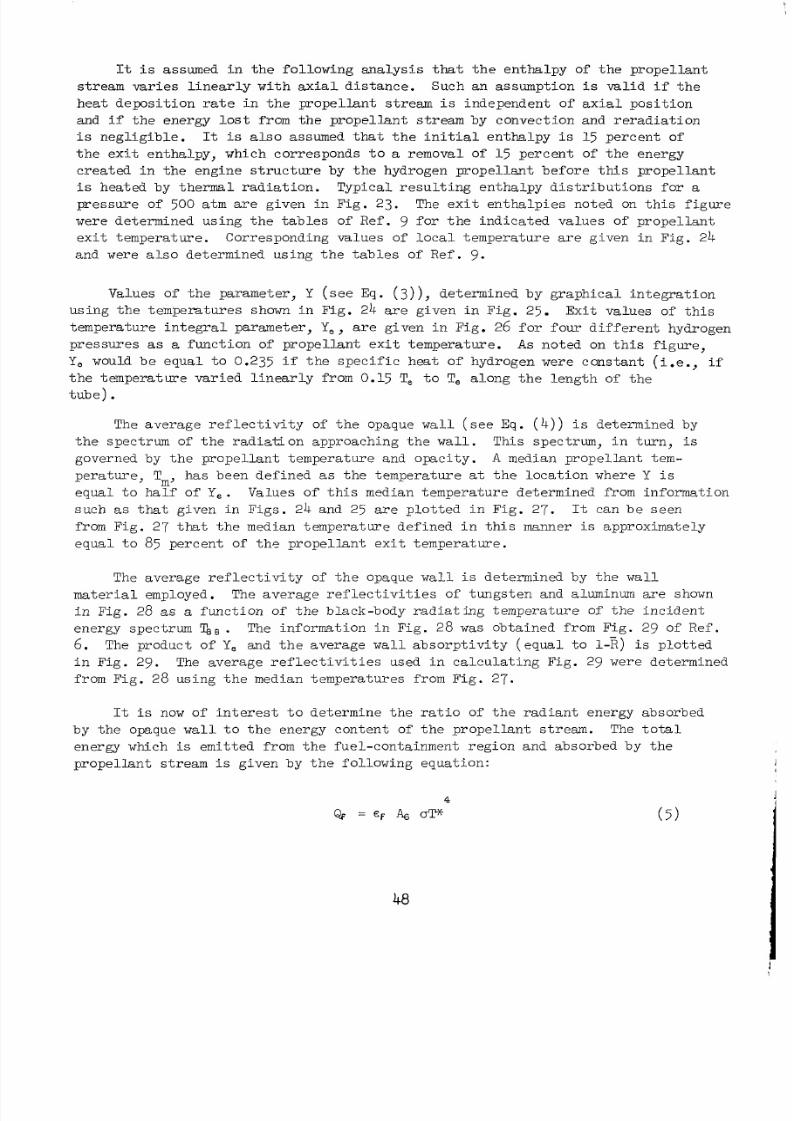
8/2/2019 Nasa Report on Gas Core Nuclear Engines
http://slidepdf.com/reader/full/nasa-report-on-gas-core-nuclear-engines 52/105
It i s assumed in the fo l low ing analysis that t h e e n t h a l p y of t h e p r o p e l l a n t
s t r e a m v a r i e s i n e a r l y w i t h a x i a l d i s t a n c e . S uc hanassumption i s v a l i d i f t h e
h e a t d e p o s i t i o n r a t e i n t h e p r o p e l l a n t s t r e a m i s i n d e p e n d e n t o f a x i a l p o s i t i o n
and i f t he ene rgy lo s t from the p rope l l an t s t r eam by convec t ion and r e r ad ia t ion
i s n e g l i g i b l e . It i s a l s o a ssumed t h a t h e n i t i a l e n t h a l p y i s 15 percen t o f
t h e e x i t e n t h a l p y , w hi chcor responds t o a removal of 1-5 percent of theenergy
c r e a t e d i n t h e e n g i n e s t r u c t u r e by t h e h yd r og e npropel lan tbefore t h i s p r o p e l l a n t
i s heated by the rm al r a d i a t i o n .T y p i c a lr e s u l t i n ge n t h a l p yd i s t r i b u t i o n s f o r apressure of 500 atm a reg i v e n nF i g .23 . The ex it e n t h a l p i e sno te d on th i s f i g u r e
werede te rminedus ing he ab le s o fRef. 9 f o r h e n d i c a t e d v a l u e s of p r o p e l l a n t
ex i t empera ture .Correspondingva lues of loca l empera tu rea reg i v e n nFig . 24
and were a l so de te rmi ned u s in g he ab le s of Re f. 9.
Valuesof theparameter , Y ( s e e Eq. ( 3 ) ) , d e t e r m i n e db yg r a p h i c a l n t e g r a t i o n
usi ng he emp era ture s shown in F ig . 24 a r eg i v e n nFig . 25. Exi tva lues of th i s
t e m p e r a t u r e n t e g r a l p a r a m e t e r , Ye , r e g i v e n i n F i g . 26 fo r fou r d i f f e r en t hydrogen
p r e s s u r e s as a func t ion of p rope l l an te x i t e m p e r a t u r e . A s noted on th is f i g u r e ,
Ye would be equ a l o 0.235 i f t h e sp ec i f i c he a t o f hyd rogenwereconstant i .e . , if
t h e e m p e r a t u r evar i ed inea r ly f rom 0.15 T, t o T, a l o n g h e e n g t h of t h et u b e ) .
The av e r ag e r e f l e c t iv i t y of t he opaque wall ( s e e E q . ( 4 ) ) i s determined by
the pec t rum of the ad ia t iona p p r o a c h i n g h e w a l l . This pec trum, in u r n , i s
governed by t h ep rope l l an t empera tu re and opac i ty . A median propellant tem-
p e r a t u r e , T, hasbeendefined as t he empera tu re a t t he oca t io n where Y i s
e q u a l oh a l fo f Ye. Valuesof t h i s median temperaturedetermined rom nformation
such as that g iven nFigs . 24and 25 a r ep l o t t e d nF i g .2 7 . It can bes e e n
from Fig . 27 ha t he median tem pe ra t ure def ine d n h is manner i s approximately
e q u a l t o 85 p e r c e nt of t h e p r o p e l l a n t e x i t e m p e r a t u r e .
The ave rag e r e f l ec t iv i ty of t he opaque w a l l i s determined by th e w a l l
ma te r ia l employed . The av er ag e re f l ec t i v i t i es of tungste n and luminum a re shown
i n F i g . 28 as a func t ion of the b lack -bodyrad ia t ing empera tu re of the nc id en t
energy pectrum . The in fo rma t ion nF i g .2 8 was obtained romFig. 9 fRef .
6. The productof Ye and thea v e r a g e wall a b s o r p t i v i t y ( e q u a l o 1-E) i s p l o t t e d
i nF i g .2 9 . The a v e r a g e e f l e c t i v i t i e s used i nc a l c u l a t i n gFi g. 29 weredetermined
from Fig . 28 usi ng he median emperaturesfromFig.27.
I t i s now of i n t e r e s t t o d e t e r m i n e t h e r a t i o of t h erad ian tenergyabsorbed
b y the opaque w a l l t o t h e e ne rg ycontent of th ep r o p e l l a n ts t r e a m . The t o t a l
energywhich i s emit ted f rom hefuel -conta inmentreg ionandabsorbedby he
p rope l l an ts t r eam i s givenby hefo l lowingequat ion :
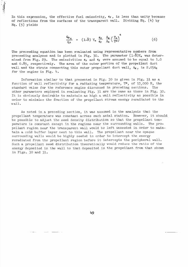
8/2/2019 Nasa Report on Gas Core Nuclear Engines
http://slidepdf.com/reader/full/nasa-report-on-gas-core-nuclear-engines 53/105
I n h i se x p r e s s i o n , th e e f f e c t i v e f u e le m i s s i v i t y , € F , i s l e s s than uni tybecause
o f e f l e c t i o n s r o m h es u r f a c e so f h e r a n s p a r e n t wall. Dividing Eq. ( 4 ) by
Eq. ( 5 ) y i e l d s
4”w R - ( L E ) Y,Q F
The preceed ing equa t i on ha s been evaluated u s i n g r e p r e s e n t a t i v e numbers from
preceed ingana lyse sand i s p l o t t e d n F i g . 30. The parameter ( l - E ) Y e w a s d e t e r -
mined fromFig. 29 . The emi s s iv i t i e s ep and EF were assumed t o b e e q u a l o 1.0
and 0.85, re spec t i ve ly . The area of the o u t e rp o r t i o no f h e p r o p e l l a n td u c t
wal l a n d h e s t r u t s c o n n e c t i n g h i s o u t e r p r o p e l l a n td u c t wall, 4,s 2.O5A,
f o r h e e n g i n e i n F i g . 4.
Informat ion s imila r t o t h a t p r e s e n t e d i n F i g . 30 i s g i v e n nF i g . 31 as a
func t i on o f w a l l r e f l e c t i v i t y f o r a r a d i a t i n g e m p e r a t u r e , W, of l5,OOO R , t h e
s t anda rdva lue o r he e fe renceeng ined i scussed i n preced ingsec t i ons . The
othe rpa rame te r s employed i n ev a lu a t i ng F ig . 3 1 a r e t h e same as t h o s e i n Fig . 30 .
It i s o b v i o u s l y d e s i r a b l e t o m a i n t a i n as high a w a l l r e f l e c t i v i t y a s p o s s i b l e i n
o r d e r t o m inim ize t h e f r a c t i o n of t h e p r o p e l l a n t s t r e a m e n e r g y r e r a d i a t e d o h e
w a l l .
A s noted i n a preced ingsec t i on , it w a s assumed in he an a ly s i s that t h e
p r o p e l l a n t e m p e r a t u r e was cons t an tac ros seach ax i a l sta t ion. However, it should
b e p o s s i b l e t o a d j u s t t h e s e e d d e n s i t y d i s t r i b u t i o n s o that t h e p r o p e l l a n t t e m -
p e r a t u r e i s cons t an te x ce p t Yn t h e e g i o n s nea r th esur rounding wal l s . The pro-
p e l l a n t r e g i o n n e a r t h e t r a n s p a r e n t w a l l would be l e f t unseeded i n o r d e r t o m ain -
t a i n a c o l db u f f e r a y e rn e x t o h i s wall . The prope l lantne ar he opaque
surrounding walls would be h igh ly seeded n o rde r o n t e rcep t he ene rgy
r e r a d i a t e d f r o m t h e p r o p e l l a n t r e g i o n b e f o r e it i n t e r c e p t s t h e p e r i p h e r a l w a l l .
Such a p r o p e l l a n t s e e d d i s t r i b u t i o n t h e o r e t i c a l l y would r e d u c e t h e r a t i o of t h e
energydeposi ted i n t h e w a l l t o that d e p o s i t e d i n t h e p r o p e l l a n t f ro m t h a t shown
i n F i g s . 30 and 31.
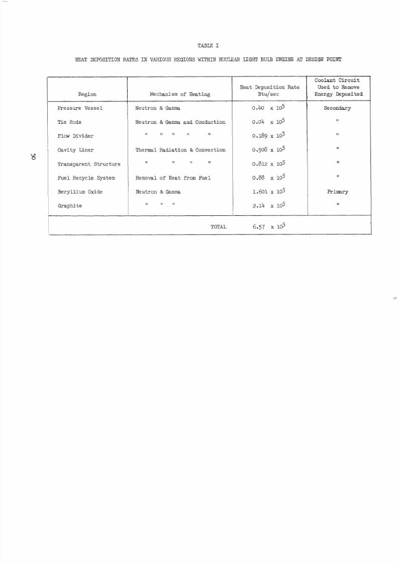
8/2/2019 Nasa Report on Gas Core Nuclear Engines
http://slidepdf.com/reader/full/nasa-report-on-gas-core-nuclear-engines 54/105
TABLE I
HEAT DEPOSITION " J E S I N VARIOUSREGIONS W I T H I N NUCLEAR =GET BUIB ENGINE AT DESIGNPOINT
Region
PressureVessel
Tie Rods
Flow Divider
CavityLiner
Transparen tStructure
FuelRecycle System
Beryllium Oxide
Graphite
~
Mechanism of Heating
Neutron & Gamma
Neutron & Gamma and Conduction
I 1 I 1 11 I 1 11
Thermal Radiation & Convection
I 1 1 1 1 1 I1
Removal of Heat rom Fue l
Neutron & Gamma
I 1 I1 11
TOTAL
Heat Deposition Rate
Btu/sec
o .40 x 105
0.04 x 10⁵
0.189 x 10⁵
0.508 x 10⁵
0.812 x 10⁵
0.88 x 10⁵
1.601x lo5
2.14 x 10⁵
6.57 x 10⁵
CoolantCircuit
Used t o Remove
Energy Deposited
Secondary
I1
11
11
Primary
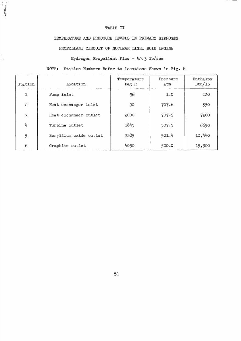
8/2/2019 Nasa Report on Gas Core Nuclear Engines
http://slidepdf.com/reader/full/nasa-report-on-gas-core-nuclear-engines 55/105
S t a t i o n"1
2
3
4
5
6~~
TABLE I1
TEMPERATURE AND PRESSURE LEXELS I N F'FUMARYHYDROGEN
PROPELLANTCIRCUIT OF NUCLEAR LIGHT BULB ENGINE
Hydrogen Propellant Flow = 42.3 l b / sec
NOTE: Station Numbers Refer t o Lo ca tio ns Shown i n F i g . 8. -
Location."
Pump i n l e t
Heat exchanger in l e t
Heatexchanger outlet
Turb ineout le t
Beryl l iumoxideout le t
G r a p h i t eo u t l e t. . - - - .~ . . _.
Pres su re
a t m
1 o
707 -6
707 *5
507.5
501.4
50 0 .o. ~~
Enthalpy
Btu/ l b
120
550
7200
6650
10) 440
15 500
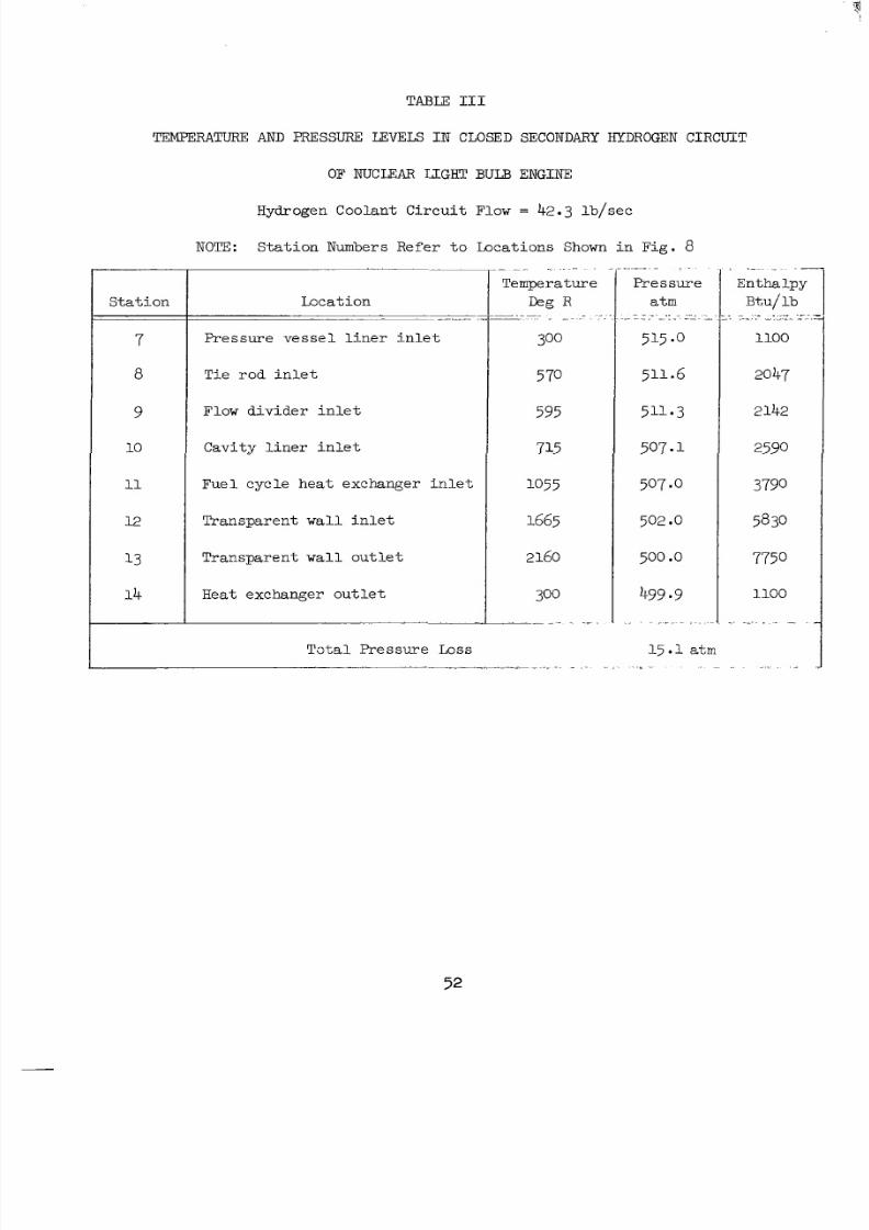
8/2/2019 Nasa Report on Gas Core Nuclear Engines
http://slidepdf.com/reader/full/nasa-report-on-gas-core-nuclear-engines 56/105
TABLE I11
TEMPERATURE AND PRESSURE LEVELS I N CLOSEDSECONDARY HYDROGEN C I R C U I T
OF NUCLEAR LCGHT B U D ENGINE
Hydrogen Co ol an t Ci rc ui t Flow = 42.3 lb/sec
NOTE: St at io n Numbers Refer t o Locat ions Shown i nF i g . 8
S t a t i o n
7
8
9
10
11
12
13
1 4
.~
Locat ion~~
~~
~
P r e s s u r e v e s s e l i n e r n l e t
T i e r o d i n l e t
Flow d i v i d e r i n l e t
C a v i t y l i n e r i n l e t
F u e l c y c l e h e a t e x c h a n g e r i n l e t
Transparent w a l l i n l e t
T ranspa ren t wall o u t l e t
Heat exchange rout le t
. . . . -
Tota l Pres sure Loss 15.1 atm
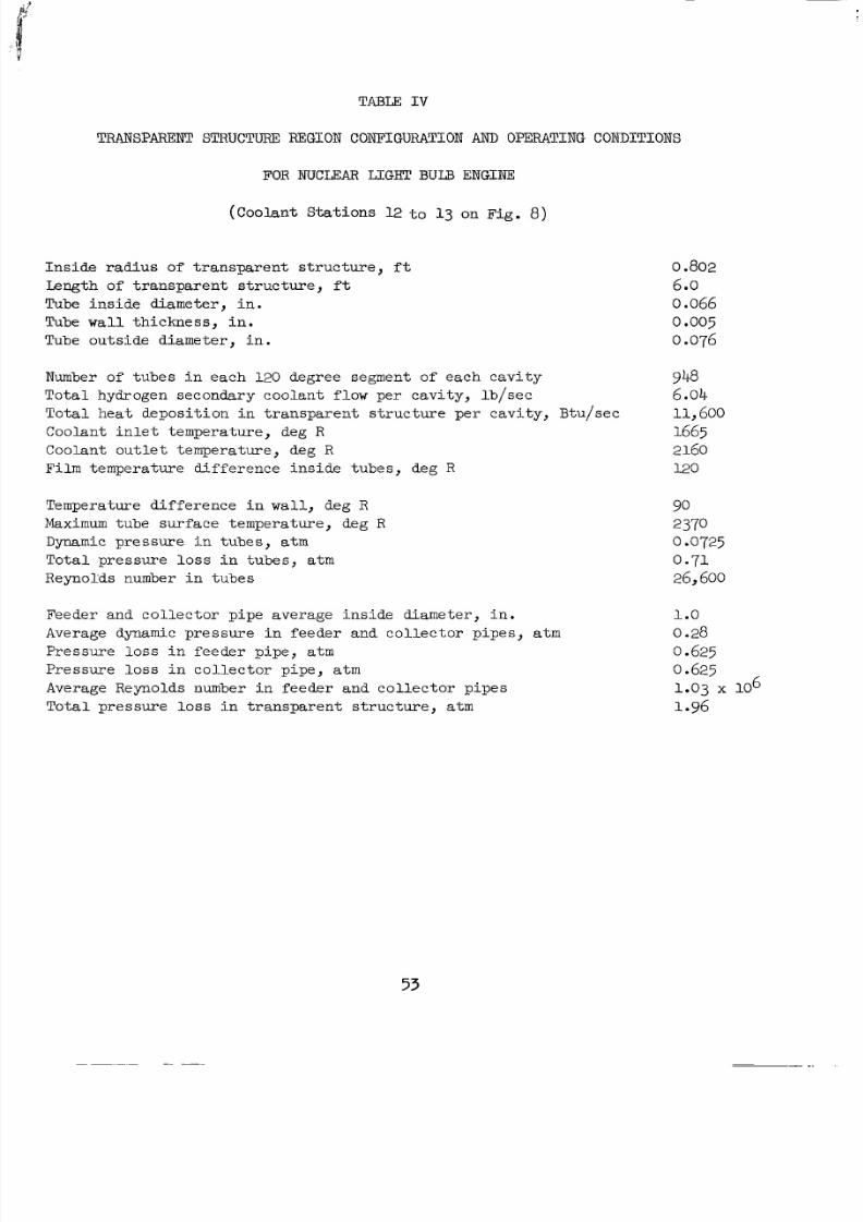
8/2/2019 Nasa Report on Gas Core Nuclear Engines
http://slidepdf.com/reader/full/nasa-report-on-gas-core-nuclear-engines 57/105
TABLE I V
TRANSPARENTSTRUCTUKE REGION CONFIGURATION AND OPERATING CONDITIONS
FOR N U C U A R LIGHT BULB ENGINE
(Coo lan t S ta t ions 12 t o 13 on Fig . 8 )
I n s i d e r a d i u s of t r a n s p a r e n t s t ru c t ur e , f t
Length of t r a n s p a r e n t s t r u c t u r e , f t
Tube insided i a m e t e r , n .
Tube wall t h i c k n e s s , n .
Tube outsided i a m e t e r , n .
Number of t u b e s n e a c h 120 degree segment o f eachcavi ty
Total hydrogensecondarycoolant lowpercavity, b/sec
To t a l h e a t d e p o s i t i o n n r a n s p a r e n t s t r u c t u r e p e r c a v i t y , B t u / s e cCoolant in le t emp eratu re , deg R
Coolan tout le t empera ture , deg R
Fi lm empera tu redi f ference nside ubes , deg R
Temperaturedi f ference i n w a l l , deg R
Maximum tubesur face empera ture , deg R
Dynamic pressure n ubes, a t m
To t a lp ressu re l o s s i n t u b e s , a t m
RepoXds number i n t u b e s
Feederandcol lec torpipeaverage nsidediameter , n .Averagedynamic p res su re n f eede r and co l l e c to r p ipe s , atm
Pressu re loss i n f e e d e r p i p e , atm
Pressu re l o s s i n c o l l e c t o r p i p e , a t m
AverageReynolds number in fe ed er an d co lle ct or pi pe s
To t a lp ressu re l o s s i n r a n s p a r e n t s t r u c t u r e , atm
o 802
6 o
o.005
o.076
948
0.066
6.04
11,6001665
2160
120
9023700 O725
0.71
26,600
1.00.28
0.625
0.625
1.03 x 10⁶
1.96
53
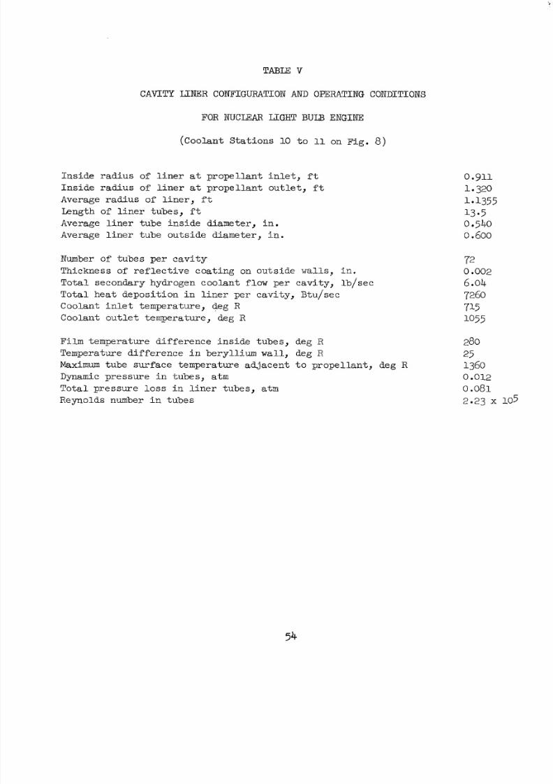
8/2/2019 Nasa Report on Gas Core Nuclear Engines
http://slidepdf.com/reader/full/nasa-report-on-gas-core-nuclear-engines 58/105
CAVITY LCNER CONFIGURATION AND OPERATING CONDITIONS
FOR NUCLFIAR U G H T BULB ENGINE
(Coo lan tS ta t ions 10 t o 11 on Fig. 8)
I n s i d e r a d i u s of l i n e r a t p r o p e l l a n t i n l e t , f t
I n s i d e r a d i u s of l i n e r a t p r o p e l l a n t o u t l e t , f t
Average rad iu s of l in er , f t
Length of l i ne r ub es , f t
Average l in er ub e ns id ed i a m e t e r , n .
Average li ne r ub eo u t s i d ed i a m e t e r , in.
Number of tu be s pe r ca vi tyThickness of ref le c t iv e c o a t i n g o n outside walls, in.
Totalsecondaryhydrogencoolantf lowpercavi ty , b /sec
To t a l h e a t d e p o s i t i o n n i n e r p e r c a v i t y , B t u / s e c
Coolant in l e t em per atu re , deg R
Coolan tout le t emperatu re , deg R
F i l m e m p e r a t u r ed i f f e r ence ns ide ubes , deg R
Temperatured i ff e rence in be r y l l ium wall , deg R
Maximum tu b es u r f a c e e m p e r a t u r ea d j a c e n t o p rope l l an t , d e g R
Dynamic pressure n ubes, atm
To t a lp r e s s u r e l o s s in l i n e r tubes , atmReynolds number i n t u b e s
0 .g11
1.320
1.135513* 504400.600
720.002
6.04
72607151055
280
25
1360
0.012
0.0812.23 X 105
54
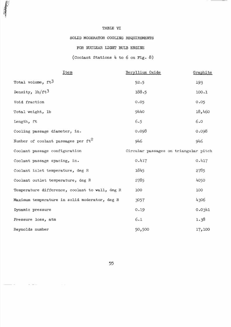
8/2/2019 Nasa Report on Gas Core Nuclear Engines
http://slidepdf.com/reader/full/nasa-report-on-gas-core-nuclear-engines 59/105
TABLE V I
S O L I D MODERATOR C O O U N G REQUIREMENTS
FOR NUCLFAR U G H " BULB ENGINE
(Coo lan t S ta t ions 4 t o 6 on Fig. 8 )
I tem
To tal volume, f t 3
D e n s i t y , b / f t 3
Void f ract ion
Tota lwe igh t , lb
Length, f t
Coolingpassagediameter , n.
Number of coolantpassagesper f t
Coolantpassageconf igurat ion
Coolantpassage pacing, n.
Coolant in l e t em per atu re , deg R
Coolan tout le t emperatu re , deg R
Temperaturedifference,coolant t o wall, deg R
Maximum t emp erat ure i n s o l i d moderator,deg R
Dynamic pressure
Pressu re loss , atm
Reynolds number
2
Berylliu m Oxide Gra phit e
52.5 193
188.5 100.1
0.05 0.05
94408,460
6.5 6O
o.098 0 og8
946
Circu la r passages on t r i ang u la r p i t ch
0.417.417
1845785
2785050
100 100
3057 4306
0.19 0.0341
6.1 1.38
50,500 17,100
55
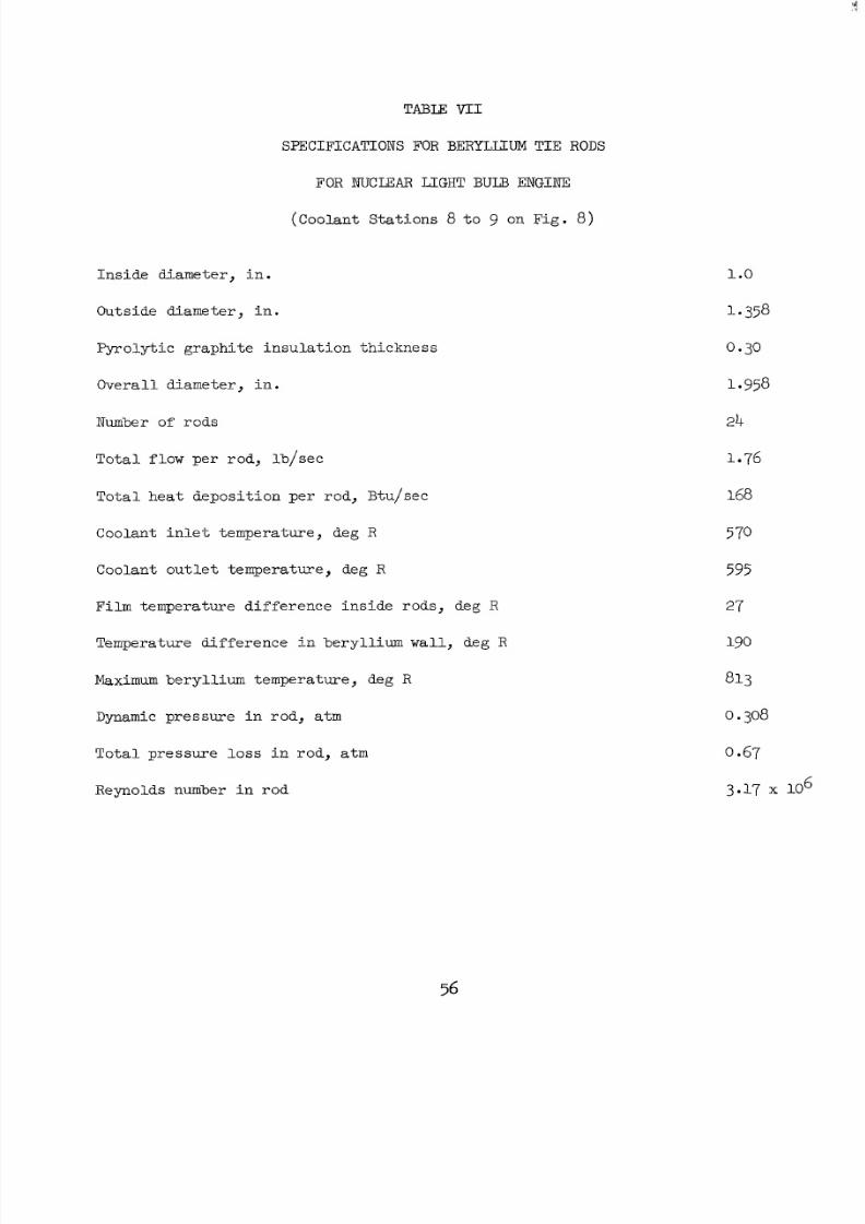
8/2/2019 Nasa Report on Gas Core Nuclear Engines
http://slidepdf.com/reader/full/nasa-report-on-gas-core-nuclear-engines 60/105
TABLE VI1
SPECIFICATIONS FORBERYLIXUM T I E RODS
FOR NUCLEAR LIGHT B U D ENGINE
(Coo lan tSta t ions 8 t o 9 on Fig. 8 )
Ins ided i a m e t e r , n .
Ou t s ided iamete r , n .
F’yroly t ic g raph i t e nsu la t ion h ickness
Overa l ld i amete r , n .
Number of rods
To t a l f low p er r o d , b / s e c
To ta l hea t depos i t ion pe r rod , Btu / sec
Coolant in l e t em per atu re , deg R
Coolan tout le t emperatu re , deg R
F i l m e m p e r a t u r e d i f f e r ence ns ide rods, deg R
Temperaturedifference i n bery l l ium wall , deg R
Maximum be ry ll iu m em pe ra tu re , deg R
Dynamic pr es su re n ro d, atm
T o t a l p r e s s u r e loss i n r o d , a t m
Reynolds number i n r o d
1 o
1 358
0.30
1.958
24
1.76
168
570
595
27
190
813
0.308
0 67
3-17 10
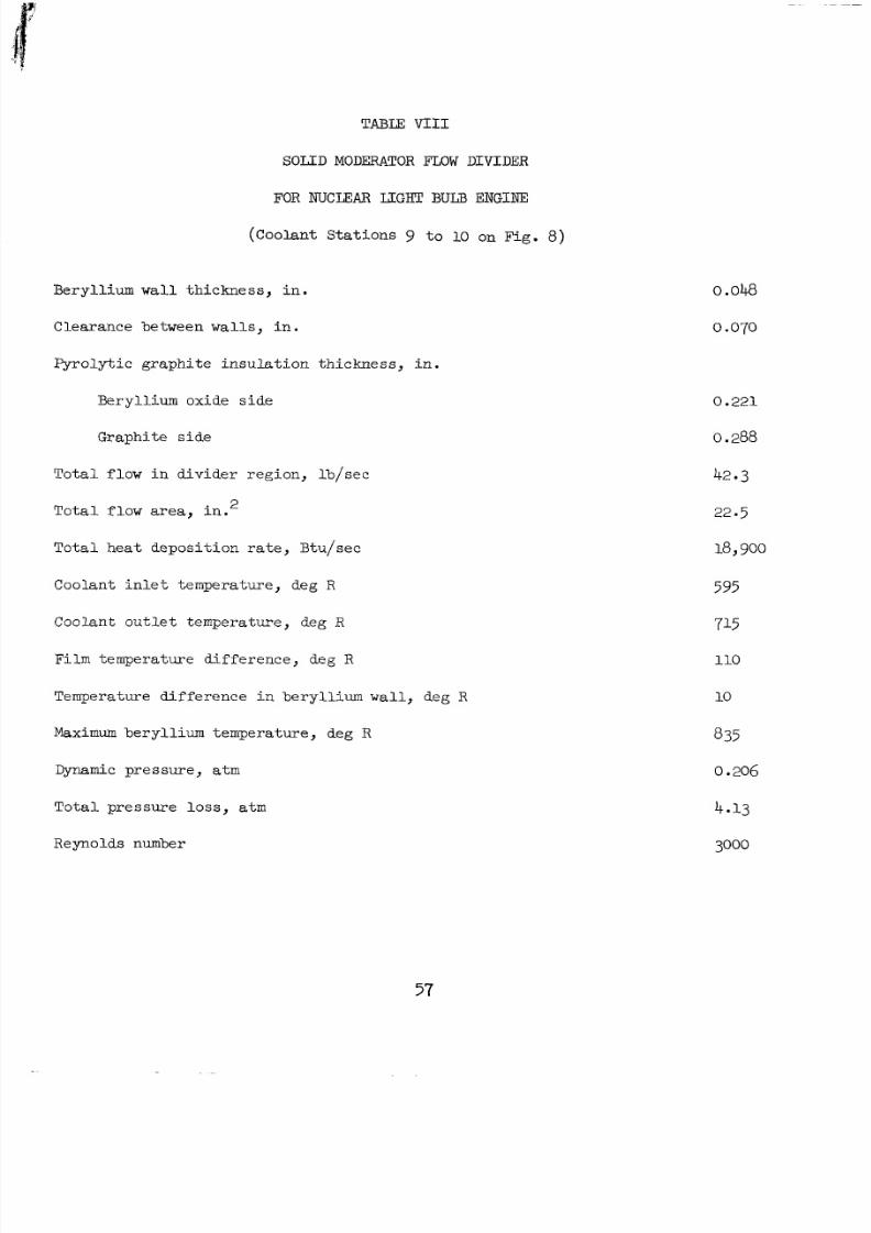
8/2/2019 Nasa Report on Gas Core Nuclear Engines
http://slidepdf.com/reader/full/nasa-report-on-gas-core-nuclear-engines 61/105
TABU VI11
S O L I D MODERATOR FLOW DIVIDER
FOR NUCIEAR LIGHT BULB ENGINE
(Coo lan tS ta t ions 9 t o 10 on Fig. 8)
Beryl l ium w a l l t h i c k n e s s , i n .
Clearancebetween walls, i n .
Pyro ly t i cg r a p h i t e n s u l a t i o n h i c k n e s s , n .
Beryll iumoxideside
Graph i t e ide
To t a l f l o w n d i v i d e r r e g i o n , b / s e c
To t a l f l o w area, i n .
To t a l h e a t d e p o s i t i o n r a t e , B t u / s e c
2
Coolant in l e t em per atu re , deg R
Coolantoutlet empera ture, deg R
Fi lm emperaturedifference, deg R
Temperatured i ff e rence in be r y l l i um wal l , deg R
Maximum be ry ll iu m em pe ra tu re , deg R
Dynamic pressure, a t m
To t a lp r e s s u r e l o s s , atm
Reynolds number
0.048
0.070
0.221
0.288
42.3
22.5
18, oo
5 95
715
110
10
8 5
0.206
4.13
3000
57
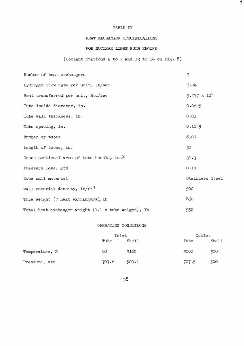
8/2/2019 Nasa Report on Gas Core Nuclear Engines
http://slidepdf.com/reader/full/nasa-report-on-gas-core-nuclear-engines 62/105
TABLE I X
HEAT EXCHANGEX SPECIFICATIONS
FOR NUCLEAR LLGW BULB ENGINE
( C o o l a n t S t a t i o n s 2 t o 3 and 13 t o 14 on Fig. 8)
Number of heatxchangers 7
Hydrogen fl ow ra te per un i t , b / sec
Heat t ransfer red per uni t , Btu/sec
Tube insided i a m e t e r , n .
Tube wall t h i c k n e s s , n .
Tube sp aci ng , n.
Number of t ubes
Length of tu be s, n.
Cross s e c t i o n a l a r e a o f t u bebundle , n .2
Pressu re loss , atm
Tube wall m a t e r i a l
Wall m a t e r i a l d e n s i t y , b / f t 3
Tube weight (7 hea t exchanger s ) , l b
6.04
3.777 x 10
0.0625
4
0.01
0.1145
6300
30
31.3
0.10
S t a i n l e s sS t e e l
500
860
Totaleatxchangereight (1.1x tubeeight ) , b 950
OPERATING CONDITIONS
Temperature , R
Pressure , a t m
I n l e t
Tubehe 11
90 2160
707 6 500.1
Out l e t
Tubehe 11
2000 300
707 5 500
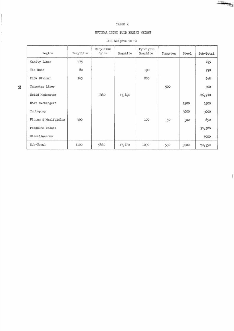
8/2/2019 Nasa Report on Gas Core Nuclear Engines
http://slidepdf.com/reader/full/nasa-report-on-gas-core-nuclear-engines 63/105
Region
Cavity Liner
Ti e Rods
Flow Divider
TungstenLiner
So lid Moderator
Heat Exchangers
Turbopump
Piping & Manifolding
PressureVessel
Miscellaneous
Sub-Total
TABm X
NUCLEAR LIGHT BULB ENGINE WEIGHT
All Weights i n Lb
Beryllium
475
80
145
400
1100
94-40
94-40
Fyrolyt ic
Graphite Graphite
~ 800
17,470
100
Tungsten
550
Steel
1900
3000
300
5200
Sub-Total
475
270
945
500
26,910
1900
,3000
850
30,500
5000
70,350
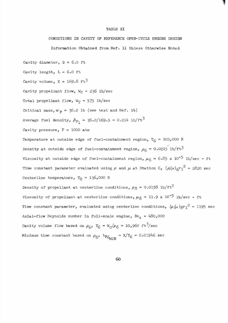
8/2/2019 Nasa Report on Gas Core Nuclear Engines
http://slidepdf.com/reader/full/nasa-report-on-gas-core-nuclear-engines 64/105
TABLE X I
CONDITIONS I N C AV IT Y OFREFERENCE OPEN-CYCm ENGINEDESIGN
InformationObtainedfrom R e f . 11 UnlessOtherwiseNoted
Cavi ty diameter , D = 6 .O f t
Cav i ty eng th , L = 6.0 f t
Cavity volume, X = 169.8 f t 3
Cavi typrope l l an tf l ow, WC = 236 lb / sec
Tota lp rope l l an tf l ow, WT = 575 lb / sec
C r i t i c a l m s s , w F = 36.2 l b ( s e e e x t a n d R e f . 1 4 )
Average fu e l de ns i ty , p~~ = 36.2/169.5 = 0.214 1 b / f t 3
Cavi typre s sure , P = 1000 a t m
Temperature a t outsideedgeoffuel-containmentregion, T6 = 102,000 R
Densi ty a t out s ide edgeoffuel-containmentregion, P 6 = 0.0215 l b / f t 3
V i s c o s i t y a t outsideedgeoffuel-containmentregion, ,U6 = 6.85 x 10⁻⁵ lb / sec - f t
Time cons tan t param eter eva lua ted us ing p and ,u a t S t a t i o n 6, (p/p)6rl2 2820 sec
Cente r l i ne empera tu re , T 8 = 136,000 R
Dens i t y o f p rope l l an t a t c e n t e r l i n e c o n d i t i o n s , p 8 = 0.0158 l b / f t 2
Vi scos i t y of p rope l l an t a t c e n t e r l in e c o n d i t i o n s , p 8 = 11.9 x 10⁻⁵ lb / sec - f t
Time constantp a r a m e t e r ,e v a l u a t e du s i n gcen t e r l i ne c o n d i t i o n s , @/,u)8r12 1195 sec
Axial-flowReynolds number i n a l l - s c a l e en g in e , Re, = 480,000
Cav ity volume flow based on ,062 ~6 = wC/,o6 = 10,960 f t see
Minimum t imeons tantased on p6, = x/y6 = 0.01546 SeC
,-
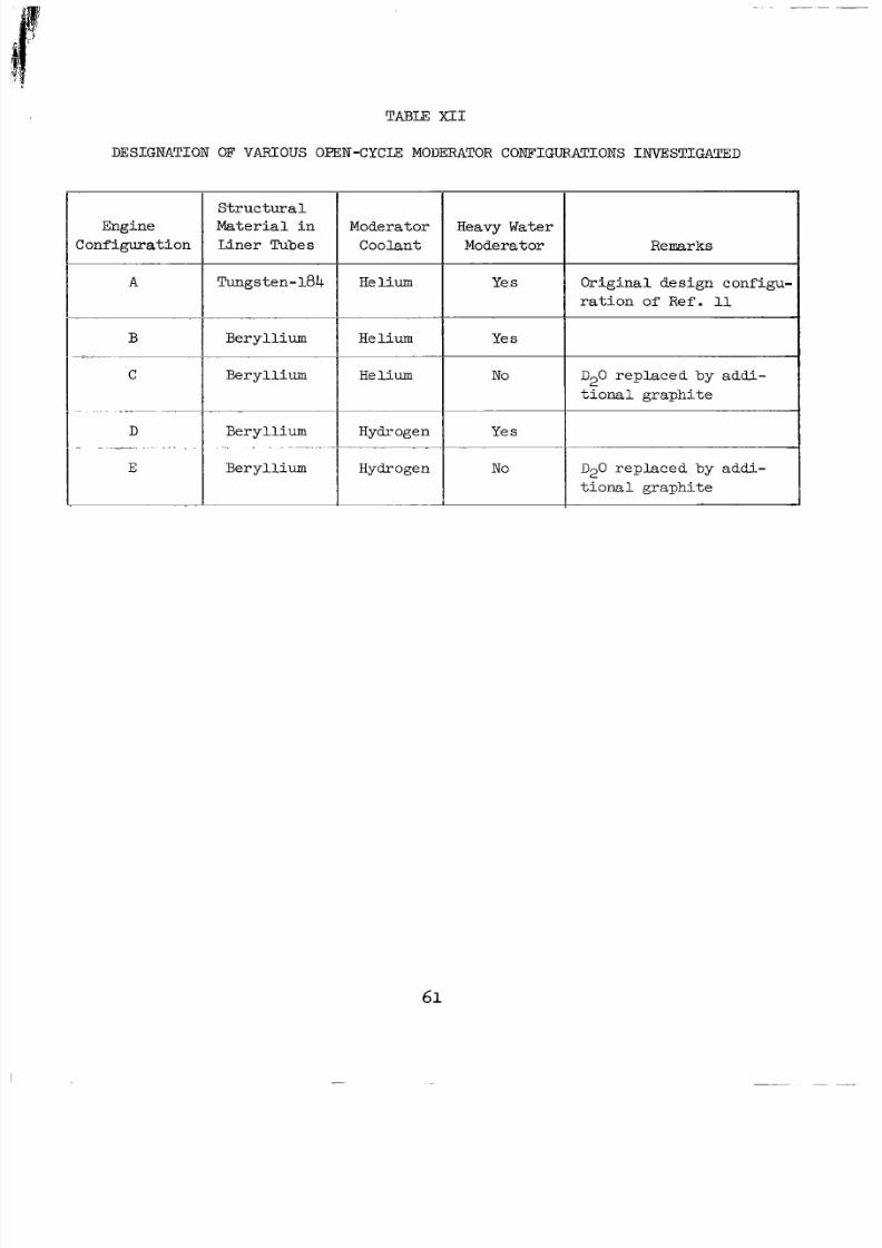
8/2/2019 Nasa Report on Gas Core Nuclear Engines
http://slidepdf.com/reader/full/nasa-report-on-gas-core-nuclear-engines 65/105
TABLE XI1
DESIGNATION OF VARIOUS OPEN-CYCLE MOUERATOR CONFIGUFATIONSNVESTIGATED
Engine
Conf igura t i on
A
B
C
S t r u c t u r a lM a t e r i a l i n
Coolantiner Tubes
Moderator
Tungsten-184 Helium
~.~ . ~.
Beryl l ium Helium
Beryl l ium Helium
Beryl l ium
Beryl l ium Hydrogen
~ . ~ ~~~~~ Iydrogen
Heavy Water
Moderator
Ye s
Ye s
No
Ye s
No
Remarks
Or ig ina l de s ign conf igu-
r a t i o n of Ref. 11
D20 rep l aced by add i -
t i o n a l g r a p h i t e
D20 replaced 'by addi-
t i o n a l g r a p h i t e
61
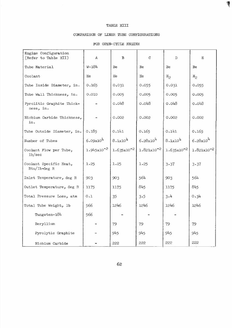
8/2/2019 Nasa Report on Gas Core Nuclear Engines
http://slidepdf.com/reader/full/nasa-report-on-gas-core-nuclear-engines 66/105
TABLE XI11
COMPARISONOF LINER TUBECONFIGURATIONS
FOR OPEN-CYCLE ENGINE
Engine Configuration(Refer t o Table XII)
Tube a t e r i a l
Coolant
Tube In sid e Diameter, i n .
Tube Wall Thickaess, n .
F yro l i t i cGraphi te Thick-
n e s s , n .
Niobium CarbideThickness,
i n .
Tube OutsideDiameter, in.
Number of Tubes
Coolant Flow per Tube,
lb / sec
CoolantSpecificHeat ,
B tu / l bdeg R
I n l e t Temperature, deg R
OutletTemperature, deg R
TotalPressure Loss, atm
To ta l Tube Weight, l b
Tungsten-184
Beryllium
Pyrolyt icGraphi te
Niobium Carbide
B
Be
He
0.031
0.005
0 ow
0.002
0.141
8. ~ 1 0 ~
1.635~10~~
1.25
90
1175
35
1246
-79
945
222
C
Be
He
0 -055
o,005
0.048
0.002
0.165
6.28~10
1.821~10'~
4
1.25
564
845
3 5
1246
-79
945
222
D
Be
H2
0.031
0.005
0 om
0.002
0.141
8. 104
1.635x1cr2
3-37
903
1175
3.4
1246
-79
945
222
E
Be
H2
0.055
0.005
0 ow
0.002
0.165
6.28~10
1.821~10-~
4
3.37
845
0.34
1246
79
945
222
62
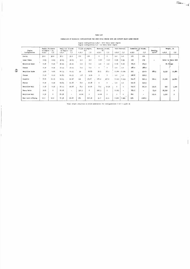
8/2/2019 Nasa Report on Gas Core Nuclear Engines
http://slidepdf.com/reader/full/nasa-report-on-gas-core-nuclear-engines 67/105
TABU X I V
COMPMISON OF MODERATOR CONFIGURATIONSOROPEN CYCLE ENGINE WITH AND WITHOW H E A V Y WATER REGION
wn
Radial Thickness
Engine of Region - i n .
c a v i ty
LinerTubes
BerylliumLiner
I I0 . 3 1 0.30
Plenum 0.30
Beryllium oxide 3.50 ',
Plenum 0.10
Graphite ~ 8.70 '
Plenum~ 0.30
,
Beryllium Wall
Heavy Water
Beryllium Wall
Heat txch & P i p i n g
0. 3
4.00
0.10
14.15
0.30
0.30
0
0
10 o
Englneconfi@ratlon A,B,D - vlth heavywater egion
Engine onfi.+ration C ,E - no heavy va te r eg ion
Volume, Void Fr ac ti on Summation of Volume,3 Ft 3
Radius a t Outside I Volme of Region,
of Revion - i n . Ft3 l-
iI
J,E 1 A , B , D
170 I 0
9.0 , 0.47
4.5 ~ 3.9
4.5 I 0
66.85
2.14
373.8
10.18
10.54
0
0
407.36
I
I
50.5 58.1.144 I 0.144 1 247
0 0 , 1.0 ~ 1.0 ! 245.8
170.227.0 0.123 0.123 ' 442.8
0 0 , 1.0 450.8.0
8.20.54
800i0.46
789.6.103297.3
459,6
31.7 22.4 0.945 O.%5 1385
* I
254.4
256.5
620.3
630.5
641.0
1048.4
Dens it ,lb,ftS
188.5
100.1
115.4
63.0
115.4
Refer t o Table XIII
I
INo Change
Tota lwe igh t educ tion n o l idmodera to rs fo r conrigura t ions C & E = 2,540 lb
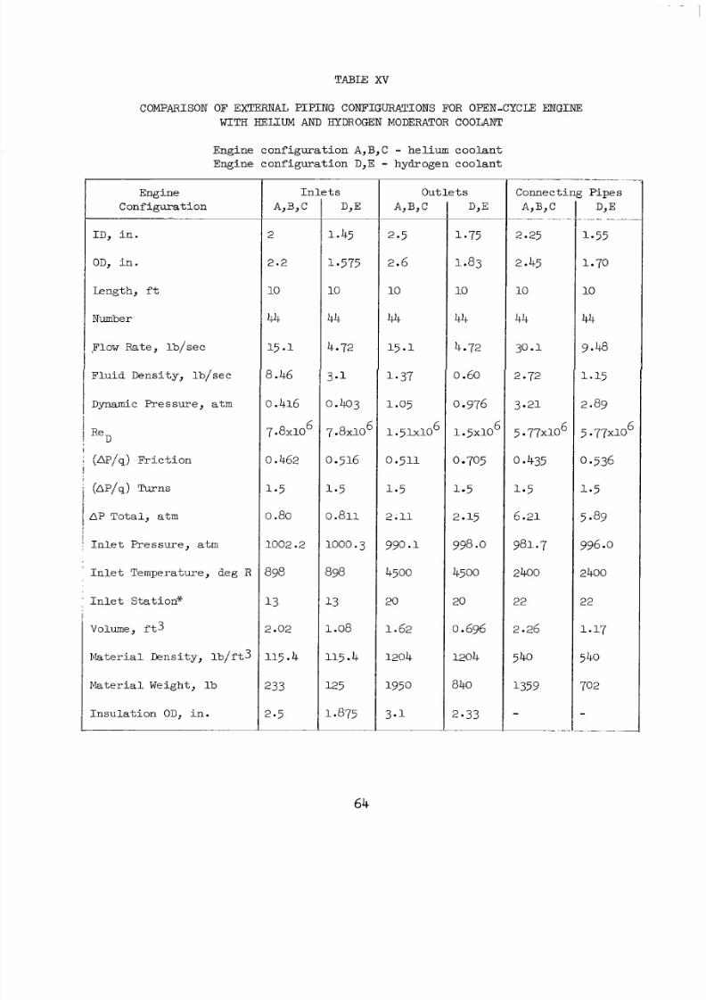
8/2/2019 Nasa Report on Gas Core Nuclear Engines
http://slidepdf.com/reader/full/nasa-report-on-gas-core-nuclear-engines 68/105
COMPARISONOF EXTERNAL PIPINGCOITJ?IGURATIONSFOR OPEN-CYCLE ENGINE
WITH €!ELCUM AND HYDROGEN MODERATOR COOLANT
Engine configuration A,B,C - helium coolant
Engine configuration D,E - hydrogen coolant
Engine
Configuration
I D , i n .
OD, i n .
Length, f t
Number
Flow Rate, b/sec
FluidDensity, b/sec
Dynamic Pressure, atrn
Re
(AP/q) Fr i c t i on
D
@/q) TlJrns
AP Total, atm
In l e tP re s sure , atm
I n l e t Temperature, deg R
In l e tSta t ion*
Volume, f t 3
Materia lDensi ty, b/f t3
Material Weight, lb
Insula t ion OD, i n .
I n
A,B,C
2
2.2
10
44
15.1
8.46
0.416
7.8~10
0.462
0.80
1002.2
398
13
? .02
115.4
233
2.5
l e Out l e t s Connecti
A,B, c~~ ~.. ~ "~2.25
2.45
10
44
30.1
2.72
3.21
5 77x10
0 *435
1.5
6.21
981.7
6
2400
22
2.26
540
1359
-~~ .-
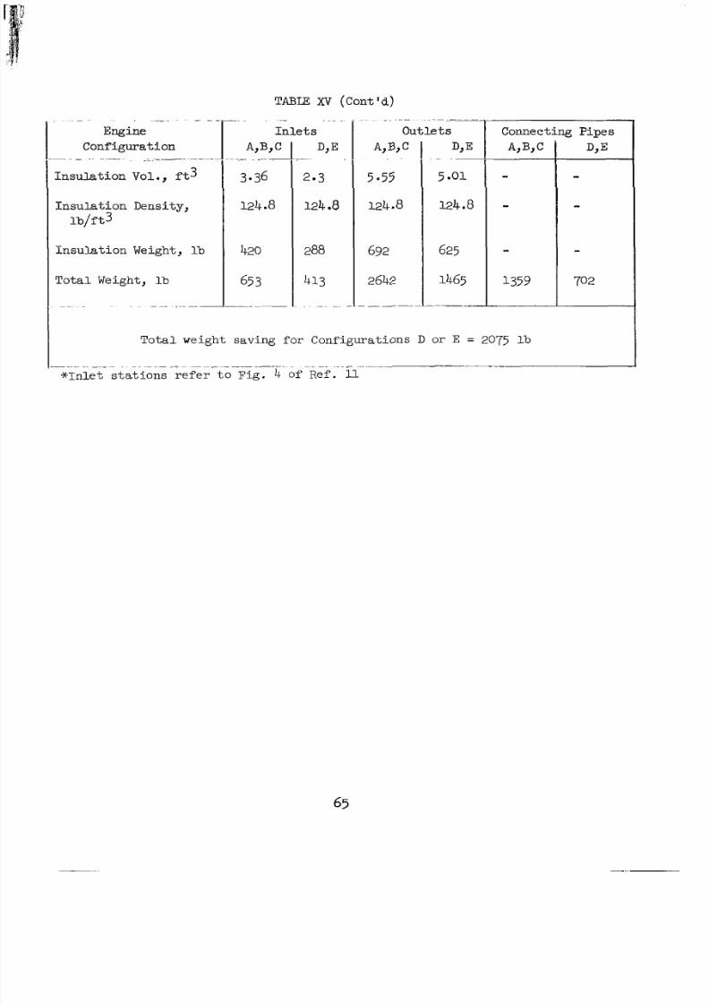
8/2/2019 Nasa Report on Gas Core Nuclear Engines
http://slidepdf.com/reader/full/nasa-report-on-gas-core-nuclear-engines 69/105
I n s u l a t i o n D e n s i t y ,
lb/ t
Insula t ion Weight , lb
Total Weight, lb
TABLE XV (Cont 'd )
3-36
124.8
420
65
.. ~
Out l e t s
5*55
124.8
ConnectingPipes
1359
Tota lwe igh tsav ing for Configura t ions D or E = 2075 lb
. ~ ~ I
* I n l e t s t a t i o n s refer t o F i g . 4 of Ref. 11.~ ~
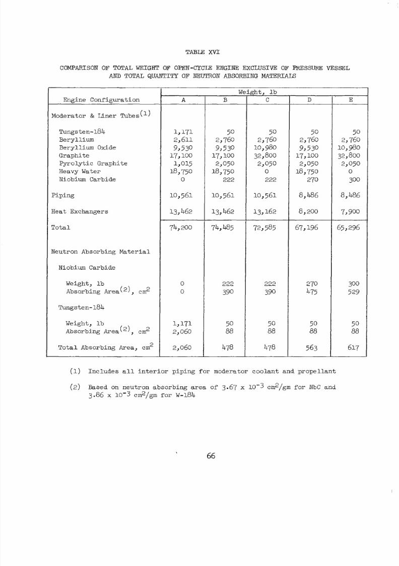
8/2/2019 Nasa Report on Gas Core Nuclear Engines
http://slidepdf.com/reader/full/nasa-report-on-gas-core-nuclear-engines 70/105
TABLE X V I
COMPARISON OF TOTAL WEIGHT OF OPEN-CYCm ENGINE: EXCLUSIVE OF PFESSURE VESSEL
AND TOTAL QUANTITY OF NEUTRON ABSORBING MATERIALS
Engine Configuration
Moderator & Liner Tubes(')
Tungsten-184
Beryllium
Beryllium Oxide
Graphi te
Pyroly t ic Graphi te
Heavy Water
Niobium Carbide
Piping
HeatExchangers
To ta l
Neutron Absorbing Ma ter ial
Niobium Carbide
Weight, l b
Absorbing Area(2), cm2
Tungsten-184
Weight, l b
Absorbing Area('), em2
To ta l AbsorbingArea, em
A
1,171
2,611
9,53017,100
1,015
l8 75'0
10,561
13,462
74,200
0
0
1,1712,060
2,060
W
50
2,76010,980
32,800
2,0500
222
10,561
13 16 2
72,585
222
390
5088
478
D
67,196
270
475
50
88
563
-
(1) Includes a l l i n t e r i o rp i p i n g for moderatorcoolantandpropel lant
E
(2 ) Based on ne ut ro nabsorbing area of 3.67 x 10⁻³ cm2/gm f o r N b C and
3.86 x 10⁻³ cm2/grn for W-184
66
8/2/2019 Nasa Report on Gas Core Nuclear Engines
http://slidepdf.com/reader/full/nasa-report-on-gas-core-nuclear-engines 71/105
TABLE XVII
TOTAL WE IGHT OF O P E N - C Y C UE N G I N EC O N F I G U R A T I O N S
I
I- I tem 1 C D
Configuration (See Tables XI1 through XVI)
4 i dPress ure vesse l nterna l volume, f t 3
Pressure vessel weight, lb
137,79663, 19645, 85 170,485 170,200otal engine weight
65, 967,1962, 854,4854,200ressurevess el see Table XVI), lb
Total weight of engine components excluding
72,5006,0002,5006,0006, 00
8/2/2019 Nasa Report on Gas Core Nuclear Engines
http://slidepdf.com/reader/full/nasa-report-on-gas-core-nuclear-engines 72/105
TABLE XYIII
RELATION B E W E E N VARIOUS MEASURES OF FUEL LOSS RATE FOR OFEN CYCLE ENGINE
Infarue t ionObta ined from Ref. 17 an dTable XI
1.0* 1 0.0000055
39.8 1 0.000218
Pay:oad E q u a l t3 One-
Tkird of that fo r
So:i.l-:xe :iu:lear
R x k e
2.32 I150 o .00822
1!I
IDimensi~nlessTi m
Z x s t a n t , T F , ~ ~3.31 1 11.95
I773 I 0.00424
I .@=o
1195
0.0000129
0.000516
0.0019'42
0.01f
0.0528
:Rat io of T o t a l
Fuello vropellantlo v
Wp = */tF t o Flow, (Fuelos t ) ,l b / s e c i 'T/F (Payloadeight) lb
2342
58.8
15.6
3.02
0.575
81,754
2 x 1
PayloadWeight)b
(MissionCost) , _
@ = 0 + 225
81,979
24261
113 338
I 21.5 246
I
Inputva lue
8/2/2019 Nasa Report on Gas Core Nuclear Engines
http://slidepdf.com/reader/full/nasa-report-on-gas-core-nuclear-engines 73/105
8/2/2019 Nasa Report on Gas Core Nuclear Engines
http://slidepdf.com/reader/full/nasa-report-on-gas-core-nuclear-engines 74/105
FIG. 1
S K ET C HE S IL L U S T R A T IN G R IN C IP L E OF OPERATION OF N U C L E A R IG H TB U L B N G IN E
a) OVERALL CONFIGURATION
M O D E R A T O R
N O Z Z L E S S E C T IO N A -A
H E A TX C H A N G E R S . IP L UM BI NG ,S E P A R A T O R S ,E T C.
4 A
U N I T C A V I T Y
b) CONFIGURATIONOFUNITCAVITYS E CT I O N B -B
S E E D E D
M O D E R A T O R P R O P E L L A N TE F L E C T IN G W A L L
T R A N S P A R E N T
”-H E R M A LR A D I A T I O N
N E O N N J E C T I O N P O R T
G A SE OU S N U C L E A R F U E L
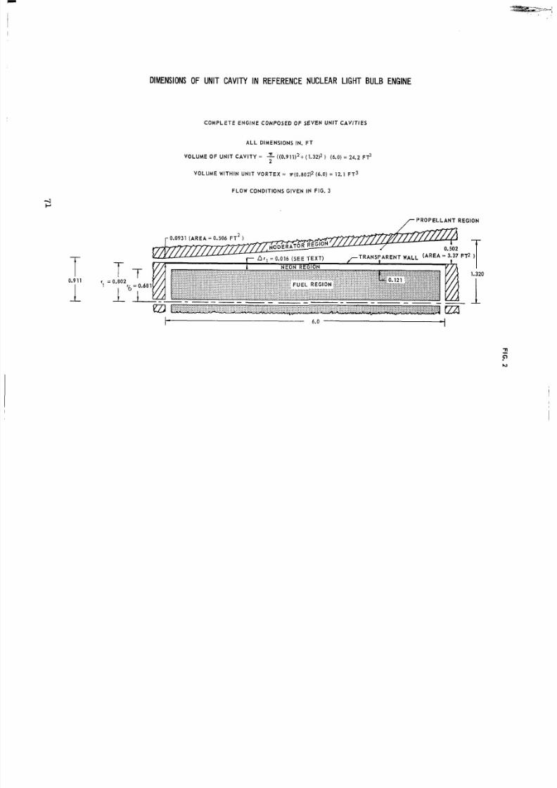
8/2/2019 Nasa Report on Gas Core Nuclear Engines
http://slidepdf.com/reader/full/nasa-report-on-gas-core-nuclear-engines 75/105
DIMENSIONS OF UNIT CAVITY IN REFERENCENUCLEAR LIGHT BULB ENGINE
CO M PLE TE ENG I NE CO M POSED O F SEVEN UNI T CAVt T lES
A LL DI M ENSI O NS N. F T
V O L U M E O F U N I T C A V I T Y = 2 L ((0.911)2+ (1.32)2 ) (6.0)= 24.2 F$2
VO LUM E WI THI N UNI T VO RTEX = ~(0.802)2 6.0)= 12.1 F T 3
FLO W CO NDI T I O NS G I VEN N F I G. 3
/ P R O P E L L A N T R E G I O N
I- 6.0 d
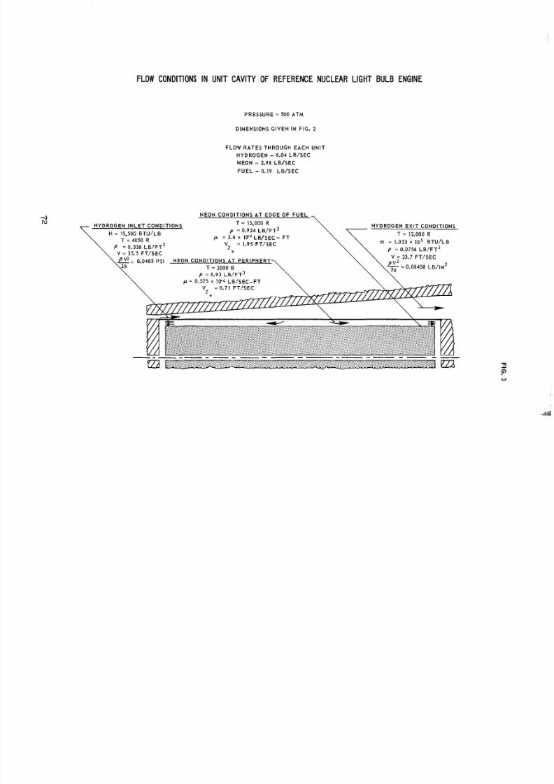
8/2/2019 Nasa Report on Gas Core Nuclear Engines
http://slidepdf.com/reader/full/nasa-report-on-gas-core-nuclear-engines 76/105
FLOW CONDITIONS IN UNITCAVITY OF REFERENCENUCLEAR LIGHT BULBENGINE
PRESSURE = 500 AT M
DIMENSIONS GIVEN N F IG . 2
FLOW RATESTHROUGH EACH UNIT
HYDROGEN - 6 . 0 4 LB/SEC
NEON - 2.96 LB/SEC
F U E L - 0.19 LB/SEC
N E O NCONDIT IONS A TE D G EO FFUEL I
w
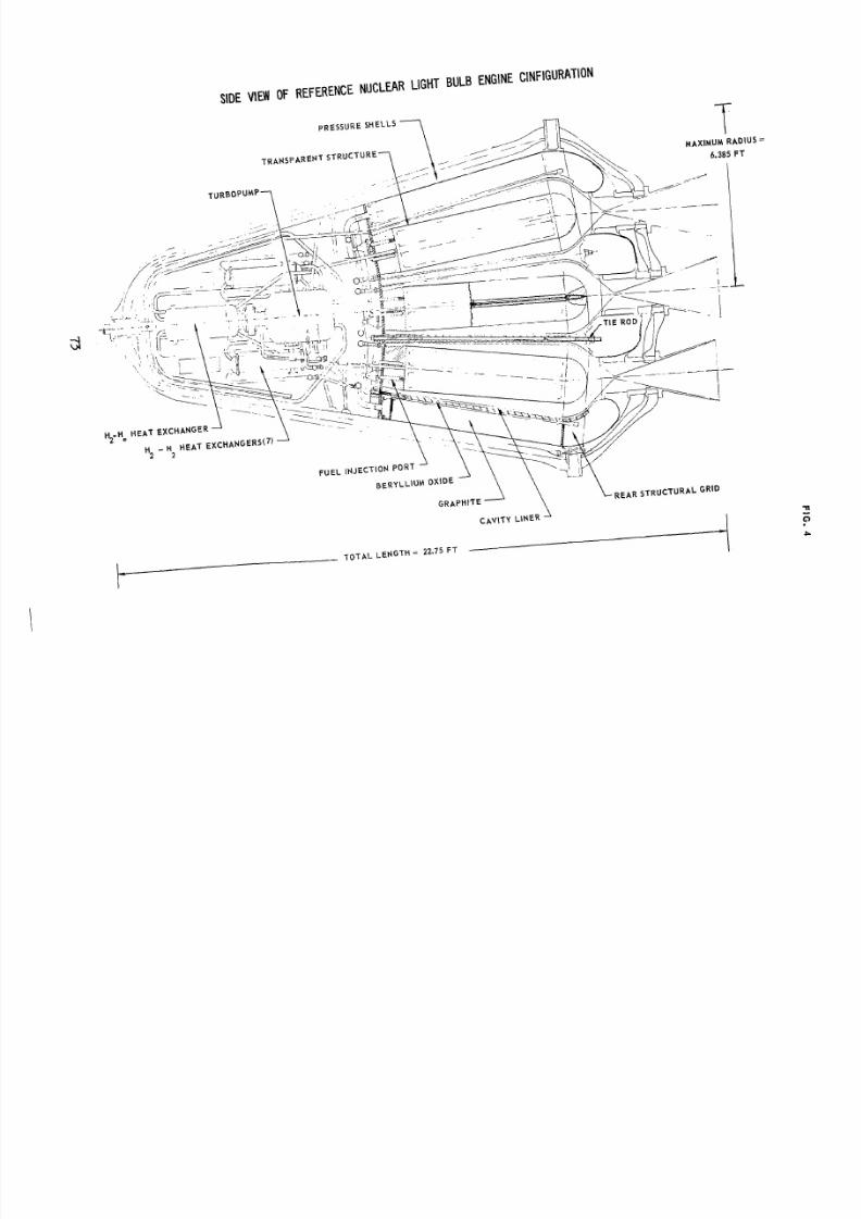
8/2/2019 Nasa Report on Gas Core Nuclear Engines
http://slidepdf.com/reader/full/nasa-report-on-gas-core-nuclear-engines 77/105
7-
P
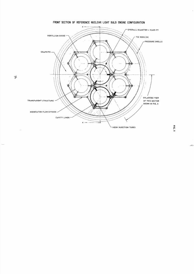
8/2/2019 Nasa Report on Gas Core Nuclear Engines
http://slidepdf.com/reader/full/nasa-report-on-gas-core-nuclear-engines 78/105
.LS
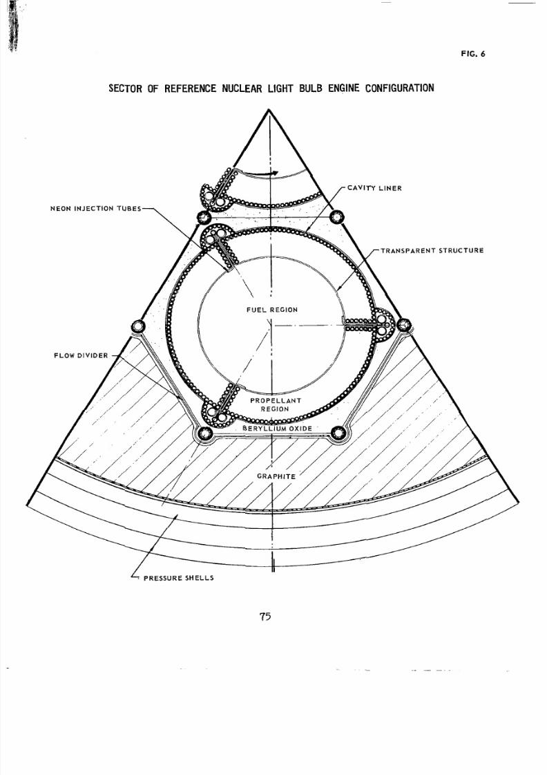
8/2/2019 Nasa Report on Gas Core Nuclear Engines
http://slidepdf.com/reader/full/nasa-report-on-gas-core-nuclear-engines 79/105
SECTOR OF REFERENCE NUCLEAR LIGHT BULB ENGINECONFIGURATION
FIG. 6
6 P R E S S U R E SHELLS
75
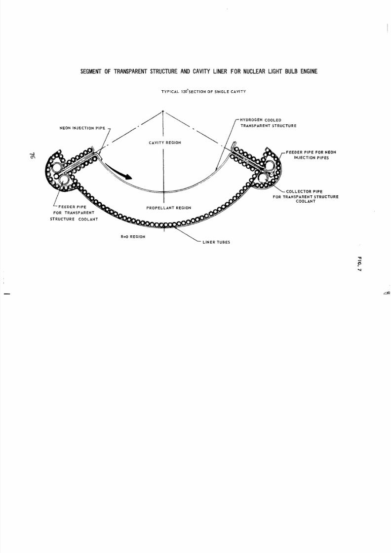
8/2/2019 Nasa Report on Gas Core Nuclear Engines
http://slidepdf.com/reader/full/nasa-report-on-gas-core-nuclear-engines 80/105
SEGMENT OF TRANSPARENTSTRUCTURE AND CAVITY LINER FO R NUCLEAR LIGHT BULBENGINE
TYPICAL 1 2 0 'SECT ION OFSINGLE CAVITY
HYDROGENCOOLED
T R A N S P A R E N T S T R U C T U R EN E O NN J E C T I O NIP E /
F E E D E R P I P E
FO RRANSPARENT
S T R U C T U R EO O L A N T
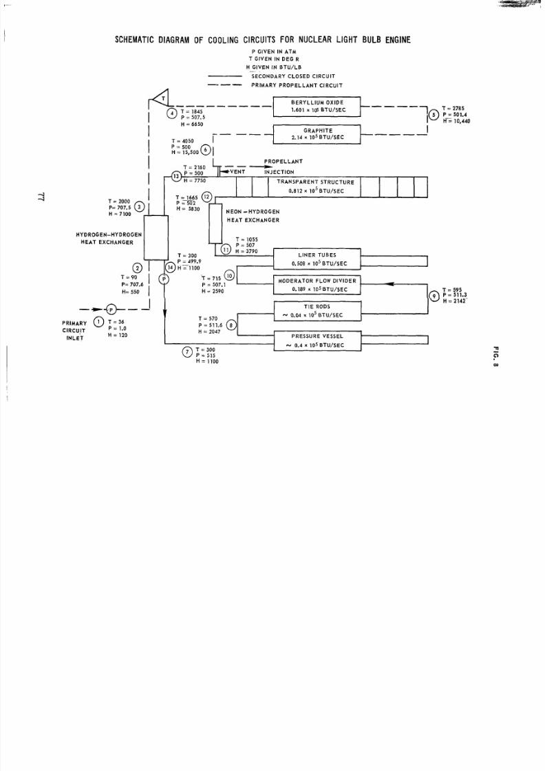
8/2/2019 Nasa Report on Gas Core Nuclear Engines
http://slidepdf.com/reader/full/nasa-report-on-gas-core-nuclear-engines 81/105
SCHEMATIC DIAGRAM OF COOLING CIRCUITS FOR N UCL EAR IGHTBULB ENGINE
P GIVEN N ATM
T GIVEN N DEG R
H G I V E N N B T U / L B-~
SECONDARY CLOSED CIRCUIT"- P R I M A R YR O P E L L A N TIRCUIT
""""_ B E R Y L L I U M O X I D E
T = 1845 1.601 x 1 s BTU/SECP = 507.5
H = 6650
5 P=501.41G R A P H I T E
IIII -0I T = 1665
= 2ooo 0
T = 4050 IP = 500H = 15,500 @I
""- 2.14 x l o 5 BTU/SEC""W
P R O P E L L A N T
INJECTIONP = 500T ~= 160 -H = 7750 TRANSPARENT STRUCTURE
i
0.812 x l o 5 BTU/SEC
P= 707.5 3
H = 7100
P = T 2H = 58 30
NEON -HYDROGEN
H E A TE X C H A N G E R
HYDROGEN-HYDROGEN
H E A T E X C H A N G E RT = 1055P = 507
T = 300 LINERUBESP = 499.9 - 1.508 x l o 5 B T W S E C
T = 90 T '715 @I MODERATOR FLOW DIV IDERP = 507.1
H = 2590 0.189 X 10⁵ B T W S E C
1-
I"@"-
T IE RODS
-H = 2142
1 - .04 X lo 5 BTU/SEC
PRIMARY 0 = 3 6
CIRCUIT = 1.0H = 120
T = 570
P = 511.6 @H = 2047
I N L E T PRESSUREVESSEL IT = 300P = 515H = 1100
~
0.4 X 10⁵ BTUISEC
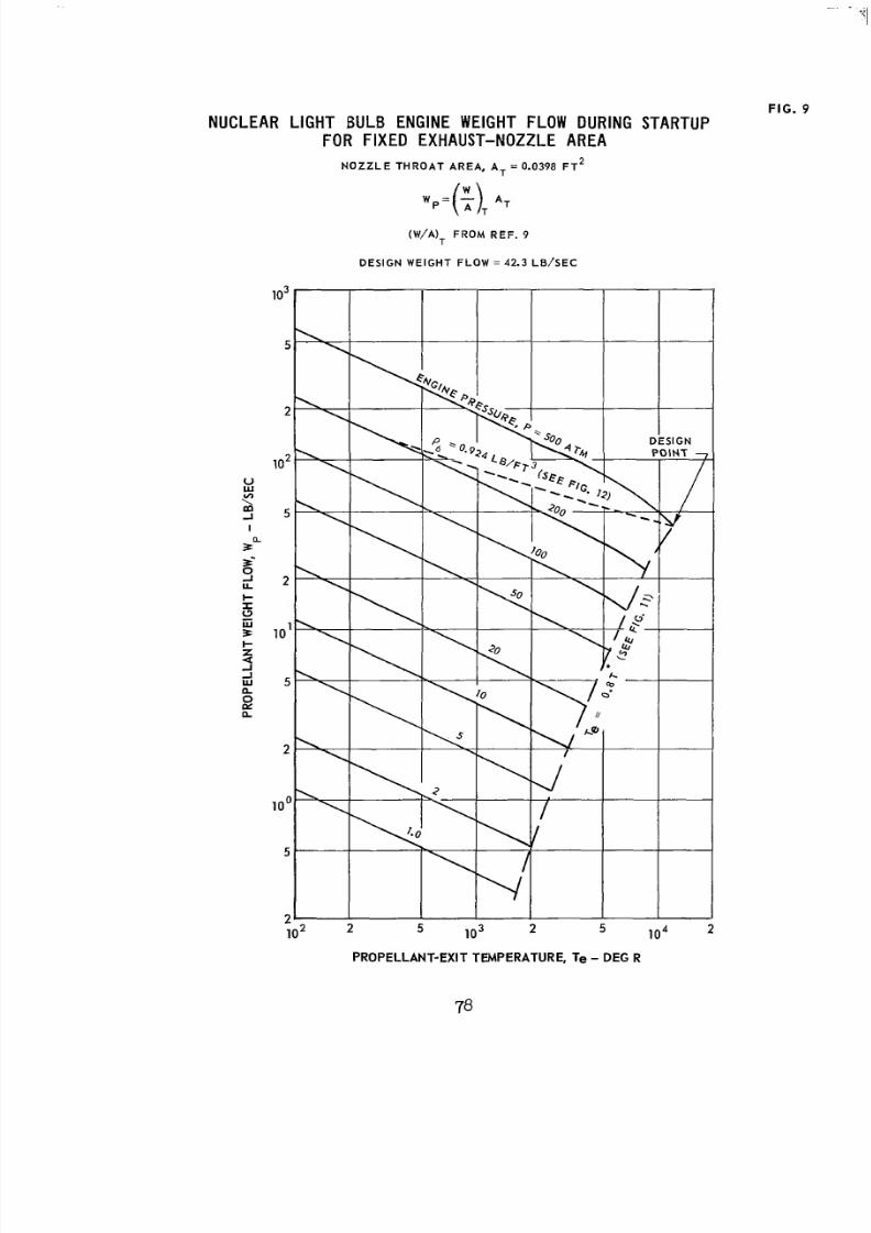
8/2/2019 Nasa Report on Gas Core Nuclear Engines
http://slidepdf.com/reader/full/nasa-report-on-gas-core-nuclear-engines 82/105
F IG . 9
N U C L E A R I G H TBULB NGINE WEIGHT FLOW DURING TARTUPFOR FIXED XHAUST-NOZZLEA R E A
N O Z Z L E T H R O A T A RE A, A T = 0 .0398 F T 2
(W/A), FR O MR E F . 9
DE S I G N WE I G HT F L O W = 42.3 L B/ S E C
I-Z
-IW
0Dia
4
a
PROPELLANT-EXIT TEMPERATURE, Te - DEG R
78
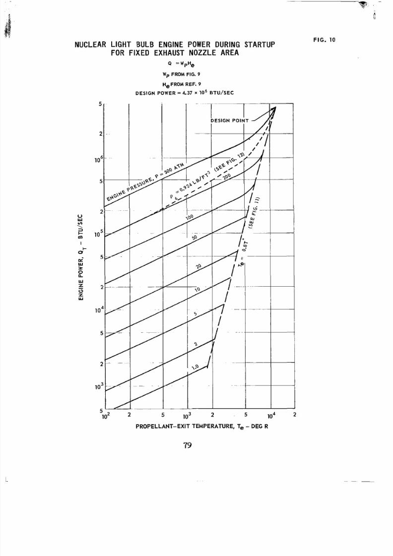
8/2/2019 Nasa Report on Gas Core Nuclear Engines
http://slidepdf.com/reader/full/nasa-report-on-gas-core-nuclear-engines 83/105
NUCLEAR IGHTBULB NGINE POWER DURING TARTUPFOR F I X E D E X H A U S TN O Z Z L EA R E A
FI G. 10
Q = Wp He
Wp FROM FIG. 9
HeFROM REF. 9
DESIGN P O W E R = 4.37 x l o 6 BTU/SEC
5
1o2 2 5 lo3 2 5 lo 4 2
PROPELLA NT-EXIT TEMPERATURE, Te - DEG R
79
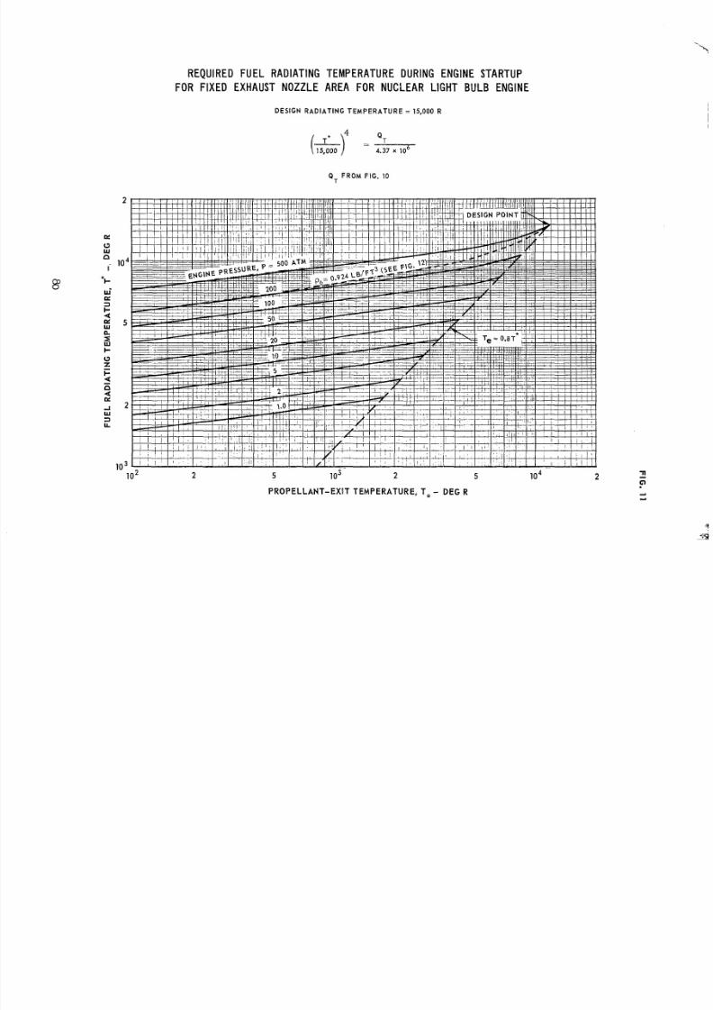
8/2/2019 Nasa Report on Gas Core Nuclear Engines
http://slidepdf.com/reader/full/nasa-report-on-gas-core-nuclear-engines 84/105
“
2
K
W(3
n
I
*I-
WK
n
d
l o 4
5
2
l o 31
R E Q U I R E D U E LRADIATING EMPERATU RE DURING ENGINE TARTUP
FOR F IXED EXHAUST NOZZLE AREA FOR N U C L E A R I G H TBULB ENGINE
D E S I G N R A D I A T I N G T E M P E R A T U R E = 15,000 R
(-r = 4.37 x 10 6
Q T
GIT F R O MFIG. 10
O 2 2 5 10: 2 5 lo 4 2 1?
PROPELLANT-EXIT TEMPERATURE, T e - DE G Rd
d
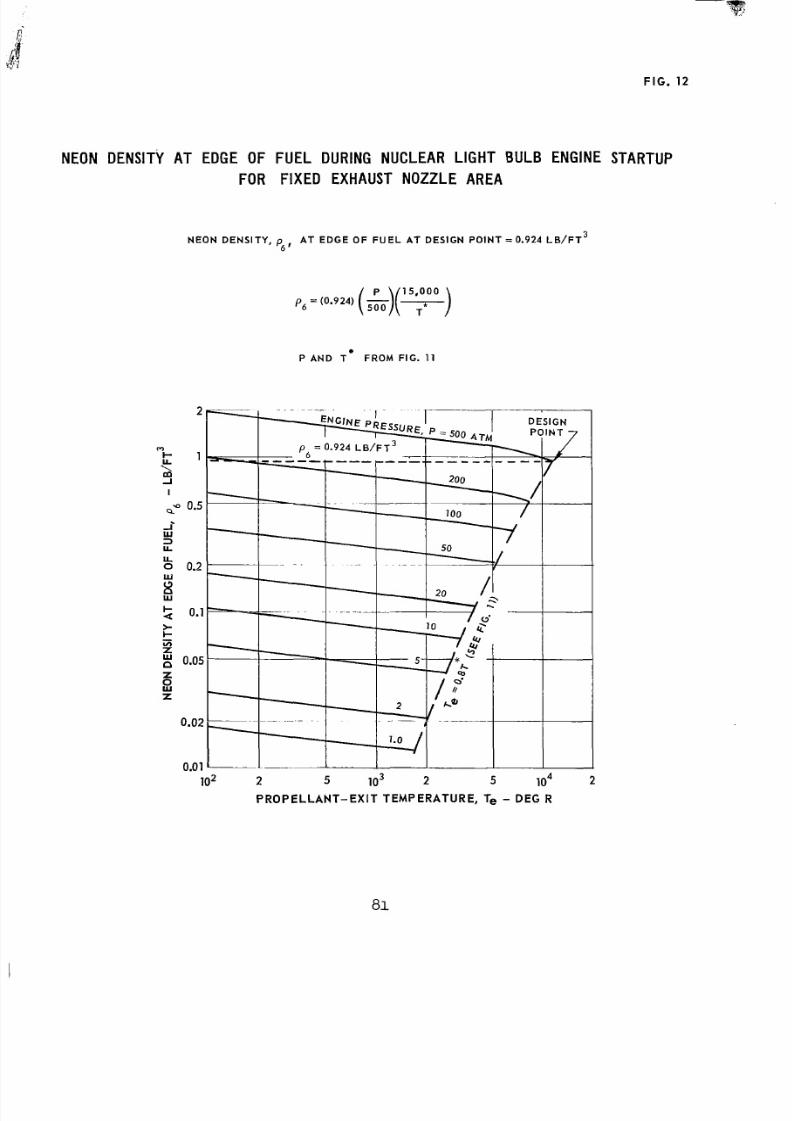
8/2/2019 Nasa Report on Gas Core Nuclear Engines
http://slidepdf.com/reader/full/nasa-report-on-gas-core-nuclear-engines 85/105
FI G. 12
NEONDENSITYATEDGEOFUEL DURING NUCLEAR IGHTBULBENGINESTARTUP
FOR FIXEDXHAUSTNOZZLE A R E A
N E O ND E N S I T Y ,A TE D G EO FF U E LA TDE S I G NP O I N T = 0.924 L B / F T 3p6 ’
P, = (0.924) (&J(7) 15,000
P AN DRO MIG . 11
2 5 lo3 2 5 lo 4 2
PROPEL LANT-EXIT TEMPERA TURE, Te - DE G R
81
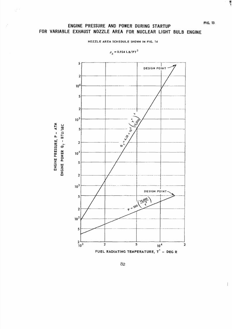
8/2/2019 Nasa Report on Gas Core Nuclear Engines
http://slidepdf.com/reader/full/nasa-report-on-gas-core-nuclear-engines 86/105
ENGINEPRESSUREANDPOWERDURINGSTARTUP
FORVARIABLEEXHAUSTNOZZLEAREA ORNUCLEAR IGHTBULB ENGINE
FIG. 13
N O Z Z L E A R E A S C H E D U L E SHOW N IN FIG. 14
p = 0.924 L B / F T 3
6
2 5 l o 4
FU EL RADIATING TEMPERATURE, T* - DE G R
82
2
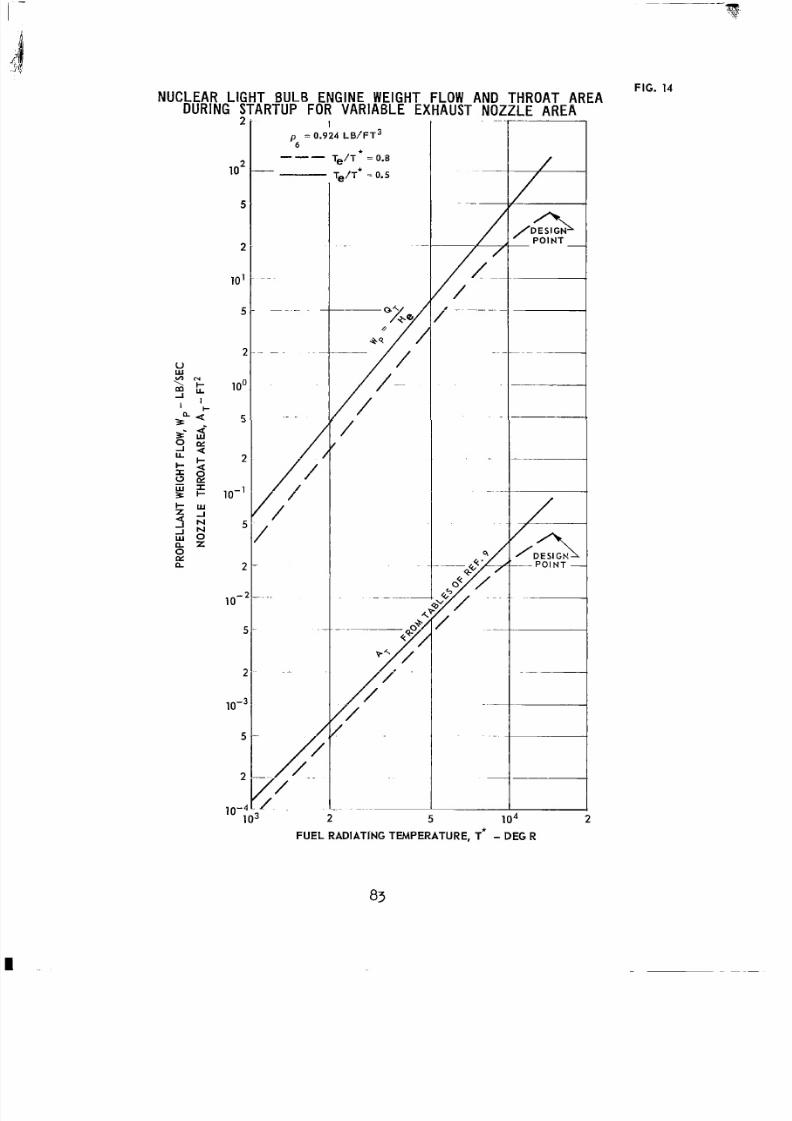
8/2/2019 Nasa Report on Gas Core Nuclear Engines
http://slidepdf.com/reader/full/nasa-report-on-gas-core-nuclear-engines 87/105
I
p = 0.924 LB/FT36
t"- T ~ / T = 0.8-Te/T* 7 0.5
"If-
2 5 l o 4
FUEL RADlATlNG TEMPERATURE, T * - DEG R
83
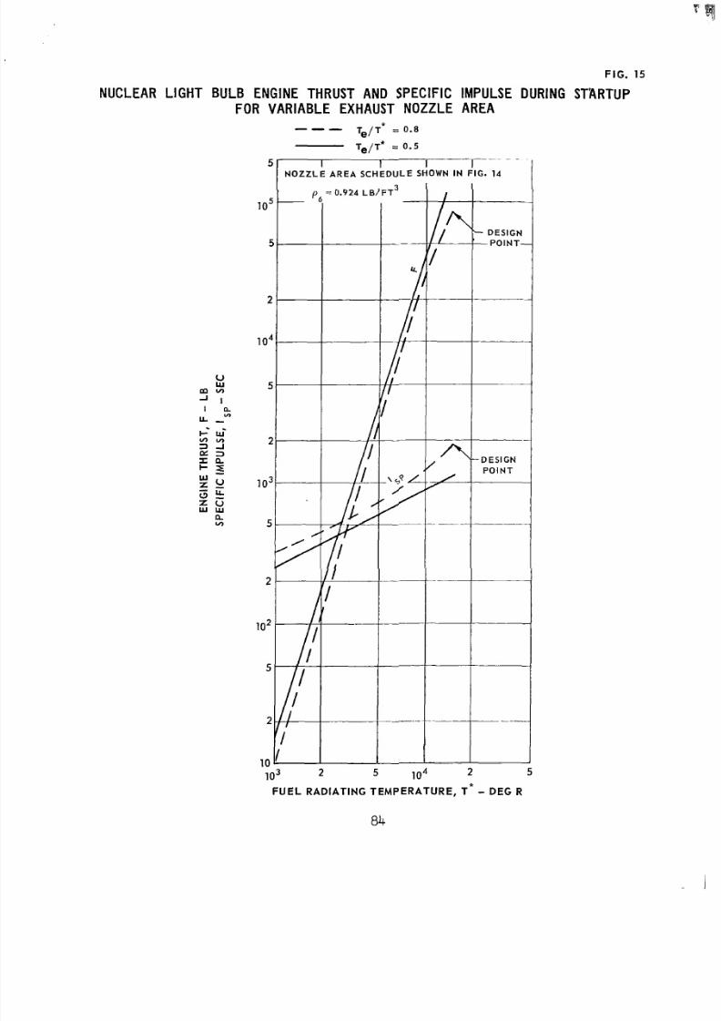
8/2/2019 Nasa Report on Gas Core Nuclear Engines
http://slidepdf.com/reader/full/nasa-report-on-gas-core-nuclear-engines 88/105
F IG . 15
NUCLEAR L IGHTBULB NGIN E HRU ST AND SPECIF ICMPULSEDURING TARTUP
F O RV A R I A B L EE X H A U S TN O Z Z L E A R E A*"- Te/T = 0.8
T=/T* = 0 .5
5 I 1 I - -
N O Z Z L E A R E A S C H E D U LE S HOWN IN F IG . 14
.-103 2 5 l o 4 2
FUEL RADIAT ING TEMPERATURE , T * - DEG R
84
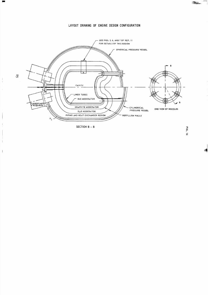
8/2/2019 Nasa Report on Gas Core Nuclear Engines
http://slidepdf.com/reader/full/nasa-report-on-gas-core-nuclear-engines 89/105
LAYOUT DRAWING OF ENGINE ESIGN ONFIGURATION
SEEFIGS. 3, 6, AN D 7 OF REF. 1 1
[ OR DETAILS O F THIS REGION
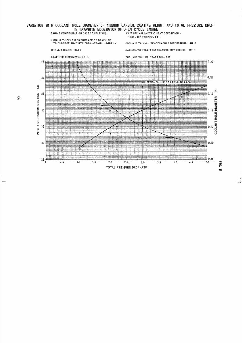
8/2/2019 Nasa Report on Gas Core Nuclear Engines
http://slidepdf.com/reader/full/nasa-report-on-gas-core-nuclear-engines 90/105
8/2/2019 Nasa Report on Gas Core Nuclear Engines
http://slidepdf.com/reader/full/nasa-report-on-gas-core-nuclear-engines 91/105
FIG. 18
POSSIBLEPRESSURE SHEL L CONFIGURATIONS
SEE A PPEND IX A
ALL DIMENSIONS IN FT
6 )
41.0
"f
IO 7
NO Z Z L E S
SI X
AT 60 °
ON E
LCONTOUR SAME AS IN CONFIG. C
8/2/2019 Nasa Report on Gas Core Nuclear Engines
http://slidepdf.com/reader/full/nasa-report-on-gas-core-nuclear-engines 92/105
/OLT HOLE 1.13 DIA )
(47 OLTSIROW)
,,,- UT RECESS (2 .2 DIA)
FIBERGLASPRESSUREVESSEL CONFIGURATION
SEE APPENDIX A
ALL DIMENSIONS IN IN.
r 3.16 TY P
THICK)
5.6 TYP2.1
34.4 R
8/2/2019 Nasa Report on Gas Core Nuclear Engines
http://slidepdf.com/reader/full/nasa-report-on-gas-core-nuclear-engines 93/105
F IG . 20
EFFECT OF IDEALIZED GLASSTRESS ON WEIGHT AND COSTOFRESSUREESSEL
40
rn
0
0
30
E
l-I
3 20-W
zWv)
U10
-
-
-
--
0 t -200 300 400 500 600
I D E A L I Z E D G LASS STRE SS L E V E L - l o 3 PSI
400
3000
z7
z 200U
Wv)
U
4
100
0
S EE A P P E N D I X A
200 300 400 500
I D E A L I Z E D GLASS STRESS L E V E L - 103 PSI
600
8/2/2019 Nasa Report on Gas Core Nuclear Engines
http://slidepdf.com/reader/full/nasa-report-on-gas-core-nuclear-engines 94/105
8/2/2019 Nasa Report on Gas Core Nuclear Engines
http://slidepdf.com/reader/full/nasa-report-on-gas-core-nuclear-engines 95/105
FIG. 22
EXPLANATION OF FILAMENT - WINDINGTERMS
t = T O T A LW A L LT H I C K N E S S
ta = T H I C K N E S SO FHELICAL WINDINGS
t o = THICKNESS OF HOOP WINDINGS
a = W I N D I N G A N G L E A T L A R G E S T R A D I U S
R a = R A D I U S T O C E N T E R O F H E L I C A L W IN DI NG S A T T A N G E N T L I N E
R = S M A L L E S TR A D I U SA TP O L A RO P E N I N GV
R c = L A R G E S T R A D I U S O F F I B E R G L A S S U P P O R T A T T I P O F P O L A R F I T T I N G F L A N G E
R E = R A D I U S T O C E N T E R O F F I L A M E N T B A N D A T P O L A R O P E N I N G
K = R E S I N B U L K F A C T O R
Ow = W A L L S TR ES S I N F I B E R G L A S C O M P O S I T E
G = STRESS IN G L A S SF I B E R S
t G= GLASSTHICKNESS
S E E A P P E N D I X A
I ,-A N G E N T ! N E
HOOP
P O L A R F I T T I N G
8/2/2019 Nasa Report on Gas Core Nuclear Engines
http://slidepdf.com/reader/full/nasa-report-on-gas-core-nuclear-engines 96/105
FIG. 23
VARIATION OF E N T H A L P Y WI T H A X I A LDIST ANC E ASSUMED IN ANALYSIS OF R A D I A N T
E N E R G Y M I T TE D FROM P R O P E L L A N T S T RE A M O F l N U C L E A R I G H TB U L B N G I N E
S E E A P P E N D I X B
P = 500 A T M
160,000
140,000
120,000
100,000
80,000
60,000
40,000
20,000
0
0 0.2 0.4.6 0.8
DIMENSIONLESS A XIAL DISTAN CE, Z/L
92
1 o
8/2/2019 Nasa Report on Gas Core Nuclear Engines
http://slidepdf.com/reader/full/nasa-report-on-gas-core-nuclear-engines 97/105
FIG. 24
K
c3u
w-K
2u
n
E
u
fI-
VARIATION OF TEMPERATUREWITHAXIALDISTANCEEMPLOYEDN
ANALYSISOFRADIANTENERGYEMITTED ROMPROPELLANTSTREAMOFNUCLEARIGHTBULBNGINE
P=500 ATM
T E M P E R A T U R E D I S T R I B U T I O N D E T E R M I N E D F R O M E N T H A L P Y
D I S T R IB U T I O N O F F I G . 2 3 U S I N G T A B L E S O F R E F . 9
S EE A P P E N D l X B
20,000
16,000
12,000
8000
4000
00 0.2 0.4 0.6 0.8 1 o
DIMENSIONLESS AXIAL DISTANCE, Z/L
93
8/2/2019 Nasa Report on Gas Core Nuclear Engines
http://slidepdf.com/reader/full/nasa-report-on-gas-core-nuclear-engines 98/105
FIG. 25
VARIATION OF TEMPERATURENTEGRALPARAMETERWITH AXIAL DISTANCE
DETERMINED FROM ANALYSIS OF ENERGYEMITTED ROM
PROPELLANTSTREAM OF NUCLEARIGHTBULBENGINES E E A P P E N D I X B
P = 500 ATM
D E T E R M I N E DFRO MT E M P E R A T U R EDIS TRIBUTIO NS I N FI G. 24
0.6
0.4
-I
\
-0N
K-WI-WI
K
L
J
4Kc3WI-
a
a
zW
3K
I-
aiwL
a
5I-
O
0.6
0.4
0.2
0
0 0.2 0.4 0.6 0.8 1 o
DIMENSIONLESS AXIAL DISTANCE, Z/L
94
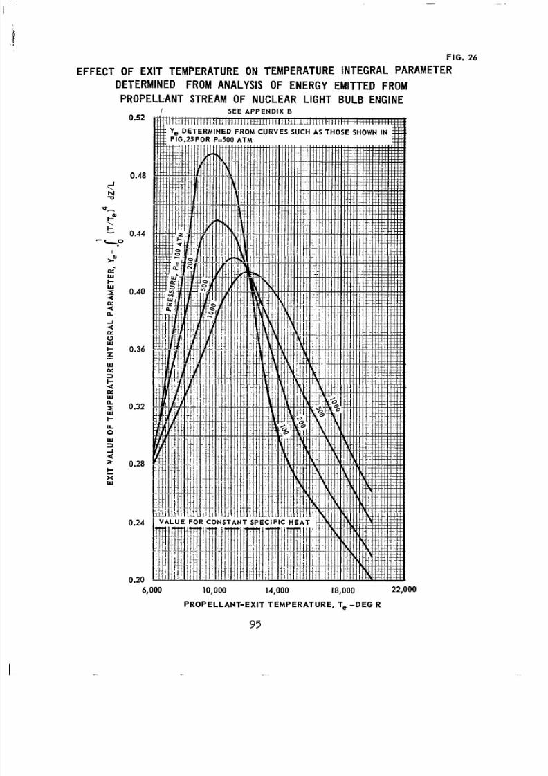
8/2/2019 Nasa Report on Gas Core Nuclear Engines
http://slidepdf.com/reader/full/nasa-report-on-gas-core-nuclear-engines 99/105
EFFE
r
FIG. 26
IRAMETER
6,000 10,000 14,000 18,000 22,000
PROPELLANT-EXIT TEMPERATURE, T, -DEG R
95
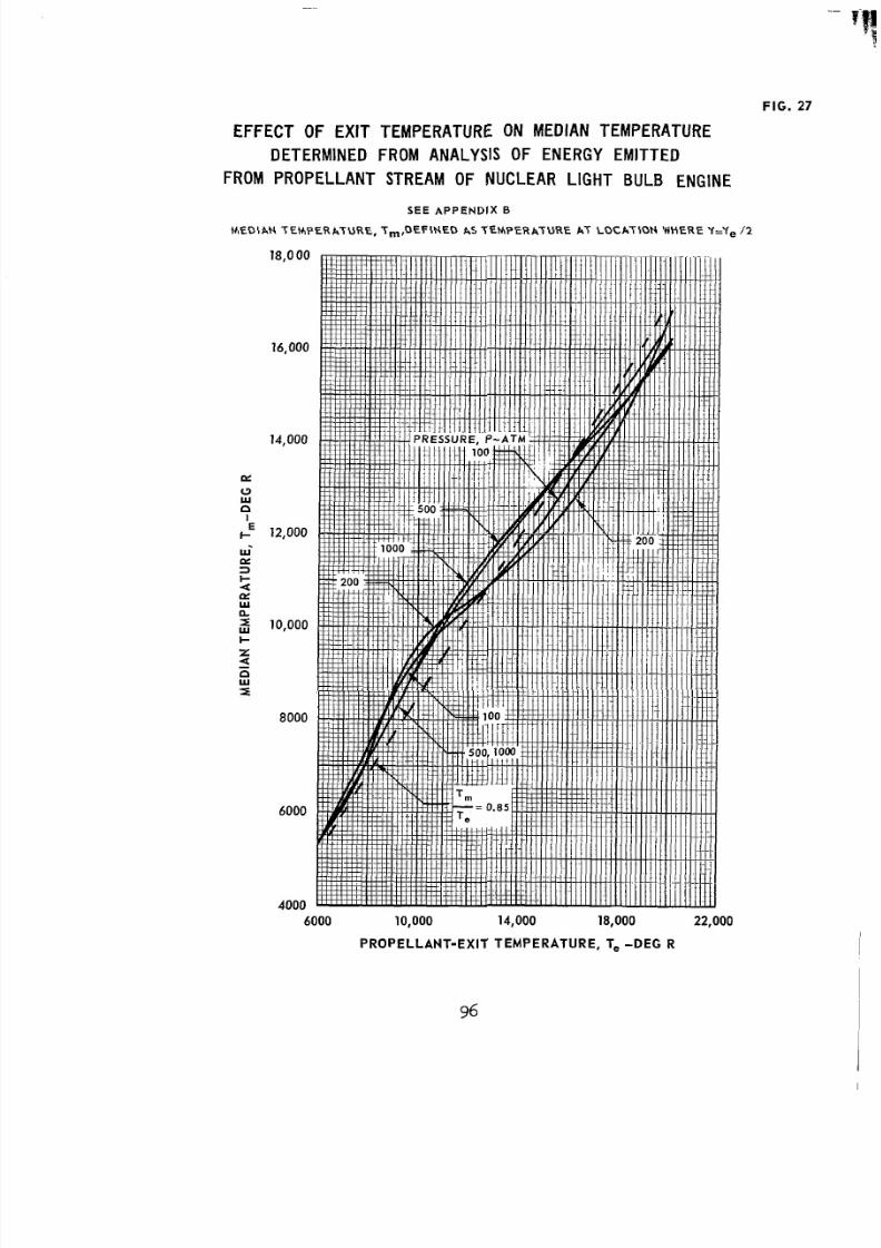
8/2/2019 Nasa Report on Gas Core Nuclear Engines
http://slidepdf.com/reader/full/nasa-report-on-gas-core-nuclear-engines 100/105
FIG. 27
EFFECT OF EXIT TEMPERATURE ONMEDIANTEMPERATURE
DETERMINED ROMANALYSISOFENERGYEMITTED
FROM PROPELLANTSTREAMOFNUCLEAR IGHT BULB ENGINE
S E E A P P E N D I X B
M E DI A N T E M P E R AT UR E , T ,, DE F INE D AS T E M P E R A T U R E A T L O C A T I O N W H E RE Y=Y, /2
18,O00
16,000
14,000
12,000
10,000
8000
6000
4000
6000 10,0004,0008,000 22,000
PRO PELLANT-EXIT TEMPERATURE, T, - DEG R
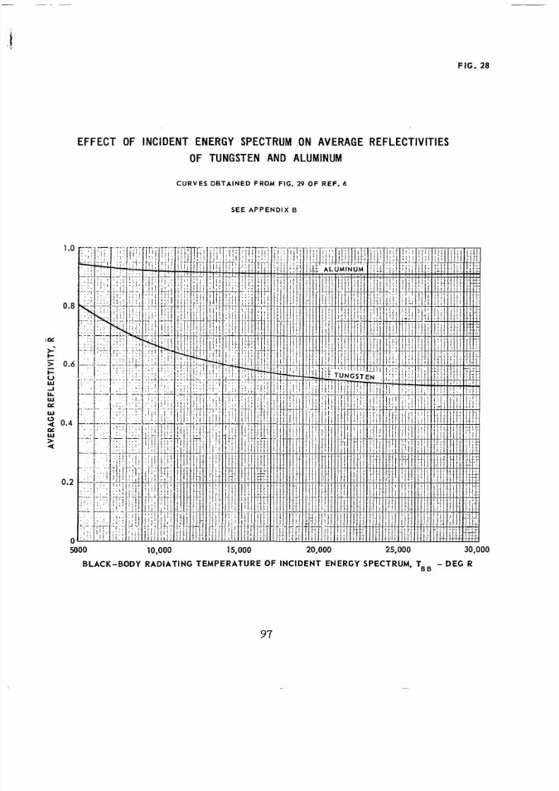
8/2/2019 Nasa Report on Gas Core Nuclear Engines
http://slidepdf.com/reader/full/nasa-report-on-gas-core-nuclear-engines 101/105
FIG. 28
1 .o
0.8
0.6
0.4
0. 2
0
E F F E C T OF IN C ID E N T E N ER G Y P E C TR U M O N A V E RA G E R E F L E C T IV IT IE S
OF TUNGSTEN AND ALUMINUM
C U R V E S O B T A I N E D F R O M F I G . 29 O F REF. 6
S E E A P P E N D I X B
so00 10,000 15,000 20,000 25,000 30,000
BLACK-BODY RAD IATING TEMP ERAT URE OF INC IDENT ENERGY SPECTRUM, T,, - DEG R
97
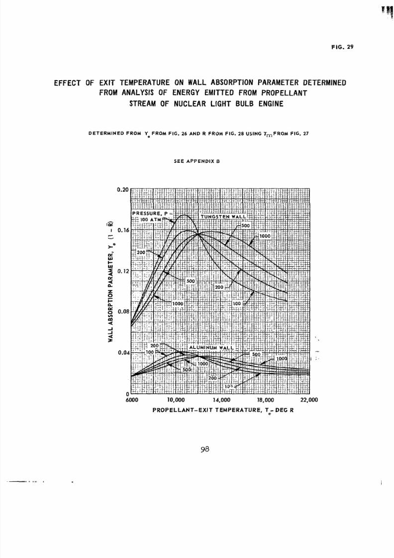
8/2/2019 Nasa Report on Gas Core Nuclear Engines
http://slidepdf.com/reader/full/nasa-report-on-gas-core-nuclear-engines 102/105
a
FIG. 29
EFFECT OF EXIT TEMPERATURE ON WALLABSORPTIONPARAMETERDETERMINED
FROMANALYSIS OF ENERGY EMITTED ROMPROPELLANT
STREAMOFNUCLEAR LIGHTBULBENGINE
D E T E R M I N E D F R O M Ye F R O M F I G . 26 AND R F RO M F I G . 28 USING TmFROM FIG. 27
S E E A P P E N D I X B
0.
K-
cw
Z
0
6000 10,000 14,000 18,000 22,000
PRO PELL ANT -EXIT TEMPERATURE, T - DEG R
8/2/2019 Nasa Report on Gas Core Nuclear Engines
http://slidepdf.com/reader/full/nasa-report-on-gas-core-nuclear-engines 103/105
EFFECT OF
LLI
FIG. 30
EXIT TEMPERATURE ON FRACTION OF ENERGY ABSORBED IN WALLDETERMINEDROMANALYSISOF ENERGY EMITTED
FROMPROPELLANTSTREAMOFNUCLEARLIGHTBULB
( 1 - E) e F R O M FIG. 29
'P = 1.0; 'F = 0.85; AA = 2.05W 6
-- U N G S T E N W A L L
AL UM I NUM WAL LS E E A P P E N D I X B
a
6000 10,000 14,000 18,000 20,000
PROPELLANT-EX I T TEM PERATURE - DEG R
99
8/2/2019 Nasa Report on Gas Core Nuclear Engines
http://slidepdf.com/reader/full/nasa-report-on-gas-core-nuclear-engines 104/105
FIG. 31
EFFECT OFWALL REFLECTIVITY ON FRACTIONOF ENERGY ABSORBED INWALLDETERMINEDROMNALYSISOF ENERGY EMITTED
FROMPROPELLANTSTREAMOFNUCLEARIGHTBULBENGINESE E A P P E N D I X B
T* = 15,000 R
Ye ' F RO MFIG. 26 FO R P= 50 0 A T M
Ep = 1.0; EF= 0.85; AW A = 2.056
CR-1030
8/2/2019 Nasa Report on Gas Core Nuclear Engines
http://slidepdf.com/reader/full/nasa-report-on-gas-core-nuclear-engines 105/105
Aeronautics and Space Administration
W A S H I N G T O N , D . C.
O F F I C I A L B U S I N E S S
-
. .
FIRST CLASS MAILNATIONAL AERONAUTIC
POSTAGE AN D FEES P
SPACE " I N I S T R A T I O
POSTMASTER: If UndeliverableSectionPostal Manual) Do Not R
"The aeronautical and space activ ities of the United States shall beconducted so ar to contribute . . . to the expansion of human knowl-
edge of phenom ena in the atmosphere and space. Th e Administration
shall provide for the wid est practicable and appropriate dissemination
of information concerning its activities and the results thereof."
" N A T I O N A L AeRoNAuncs A N D SPACE ACT OF 1958
NASA SCIENTIFIC A N D TECHNICAL PUBLICATIONS
TECHNICAL REPORTS:Scientific and technical information considered
important, complete, and a lasting contribution to existing .knowledge.
TECHNICAL NOTES: Information less broad in scope but nevertheless of
importance as a contribution to existing knowledge.
TECHNICAL MEMORANDUMS: Information receiving limited distribu-
tion because of preliminary data, security classification,or other reasons.
CON TRA mOR REPORTS:Scientific and technical information generated
under a NASA contract or grant and considered an important contribution to