Embed Size (px)
Citation preview
PHYSICAL SCIENCE &ENGINEERING DESIGNhttp://scifiles.larc.nasa.gov
www.nasa.gov
EG-2005-05-04-LARC
Educational Product
Educators Grades 3–8
P H Y S I C A L S C I E N C E & E N G I N E E R I N G D E S I G NWith this booklet and some cardboard, wheels, and other components, you can change the world. You can excite children’s interests in science and engineering and steer some towards careers in technical fi elds that they might not have otherwise considered.
Children come into the world natural learners – eager to explore, build and test. But, we suppress this natural curiosity, especially for girls and minorities. Now you can rekindle that love of learning by encouraging them to take ownership of their inquiry, trust their own thinking, and expand their own skills.
Th ey need challenges and people to encourage them to take on those challenges in their own way. Open the door to learning, not through lecturing and showing, but by stimulating and permitting exploration. Don’t fear that they will ask things you don’t know – fear that they won’t ask anything and that you will have squandered the opportunity to change the world.
Use this booklet to launch children into exploring their universe. Help them explore. Learn as they learn and share the excitement of discovery.
Ed Sobey, Ph.D. Northwest Invention Center
NATIONAL SCIENCE EDUCATION STANDARDS Physical Science
Position and Motion of Objects (K-4)
• The position and motion of objects can be changed by pushing or pulling. The size of the change is related to the strength of the push or pull.
Motions and Forces (5-8)
• The motion of an object can be described by its position, direction of motion, and speed.
• An object that is not being subjected to a force will continue to move at a constant speed and in a straight line.
• If more than one force acts on an object along a straight line, then the forces will reinforce or cancel one another, depending on their direction and magnitude. Unbalanced forces will cause changes in the speed or direction of an object’s motion.
Science and Technology
Abilities of Technological Design (K-4, 5-8)
• Identify a simple problem.
• Propose a solution.
• Implementing proposed solutions.
• Evaluate a product or design.
• Communicate a problem, design, and solution.
Understanding About Science and Technology (K-4, 5-8)
• People have always had problems and invented tools and techniques (ways of doing something) to solve problems. Trying to determine the effects of solutions helps people avoid some new problems. (K-4, 5-8)
• Scientific inquiry and technological design have similarities and differences. Scientists propose explanations for questions about the natural world, and engineers propose solutions relating to human problems, needs, and aspirations. (5-8)
• Perfectly designed solutions do not exist. All technological solutions have trade-offs, such as safety, cost, efficiency, and appearance. Engineers often build in back-up systems to provide safety. (5-8)
Science in Personal and Social Perspectives
Science and Technology in Local Challenges (K-4)
• People continue inventing new ways of doing things, solving problems, and getting work done. New ideas and inventions often affect other people; sometimes the effects are good and sometimes they are bad.
2004–2005 NASA SCI Files™ Serieshttp://scifiles.larc.nasa.gov
3
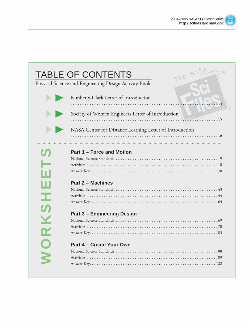
Kimberly-Clark Letter of Introduction. . . . . . . . . . . . . . . . . . . . . . . . . . . . . . . . . . . . . . . . . . . . . . . . . . . . . . . . . . . . . . . . . . . . . . . . . . . . . . . . . . . . . . .4
Society of Women Engineers Letter of Introduction . . . . . . . . . . . . . . . . . . . . . . . . . . . . . . . . . . . . . . . . . . . . . . . . . . . . . . . . . . . . . . . . . . . . . . . . . . . . . . . . . . . . . . .5
NASA Center for Distance Learning Letter of Introduction. . . . . . . . . . . . . . . . . . . . . . . . . . . . . . . . . . . . . . . . . . . . . . . . . . . . . . . . . . . . . . . . . . . . . . . . . . . . . . . . . . . . . . .6
Part 1 – Force and Motion
National Science Standards . . . . . . . . . . . . . . . . . . . . . . . . . . . . . . . . . . . . . . . . . . . . . . . . . . . . . . . . . . . . 9
Activities . . . . . . . . . . . . . . . . . . . . . . . . . . . . . . . . . . . . . . . . . . . . . . . . . . . . . . . . . . . . . . . . . . . . . . . . . . . . 10
Answer Key . . . . . . . . . . . . . . . . . . . . . . . . . . . . . . . . . . . . . . . . . . . . . . . . . . . . . . . . . . . . . . . . . . . . . . . . . . 38
Part 2 – MachinesNational Science Standards . . . . . . . . . . . . . . . . . . . . . . . . . . . . . . . . . . . . . . . . . . . . . . . . . . . . . . . . . . . 43
Activities . . . . . . . . . . . . . . . . . . . . . . . . . . . . . . . . . . . . . . . . . . . . . . . . . . . . . . . . . . . . . . . . . . . . . . . . . . . . 44
Answer Key . . . . . . . . . . . . . . . . . . . . . . . . . . . . . . . . . . . . . . . . . . . . . . . . . . . . . . . . . . . . . . . . . . . . . . . . . . 64
Part 3 – Engineering DesignNational Science Standards . . . . . . . . . . . . . . . . . . . . . . . . . . . . . . . . . . . . . . . . . . . . . . . . . . . . . . . . . . . 69
Activities . . . . . . . . . . . . . . . . . . . . . . . . . . . . . . . . . . . . . . . . . . . . . . . . . . . . . . . . . . . . . . . . . . . . . . . . . . . . 70
Answer Key . . . . . . . . . . . . . . . . . . . . . . . . . . . . . . . . . . . . . . . . . . . . . . . . . . . . . . . . . . . . . . . . . . . . . . . . . . 83
Part 4 – Create Your OwnNational Science Standards . . . . . . . . . . . . . . . . . . . . . . . . . . . . . . . . . . . . . . . . . . . . . . . . . . . . . . . . . . . 88
Activities . . . . . . . . . . . . . . . . . . . . . . . . . . . . . . . . . . . . . . . . . . . . . . . . . . . . . . . . . . . . . . . . . . . . . . . . . . . . 89
Answer Key . . . . . . . . . . . . . . . . . . . . . . . . . . . . . . . . . . . . . . . . . . . . . . . . . . . . . . . . . . . . . . . . . . . . . . . . . 122
TABLE OF CONTENTSPhysical Science and Engineering Design Activity Book
WO
RK
SH
EE
TS
2004–2005 NASA SCI Files™ Serieshttp://scifiles.larc.nasa.gov44
November 1, 2005
Kimberly-Clark is pleased to collaborate on this activity book with NASA SCI Files™ and the Society of Women Engineers (SWE). Kimberly-Clark considers education integral to the quality of life. Our company and its employees are active sponsors of education, whether it is through monetary donations, our employees’ time and talents in the communities they live, or through projects such as NASA SCI Files™ and SWE. Sponsoring this activity book offers us the opportunity to help you as you guide your students’ development for the future.
Because innovation and new product development are cornerstones of our success, both science and engineering are heavily emphasized and highly regarded. Technical experience, combined with other skills like creativity and problem solving, allow us to identify a consumer need and create products that enhance their health, hygiene and well-being. Learning and applying science and engineering can inspire students to be curious, creative, and avid problem-solvers - skills that are valuable in any career path your students with take in life.
We hope that this activity book will be an exciting tool for teaching and transforming your students’ perceptions of the world, and inspire their inquisitiveness, confidence, and creativity.
2004–2005 NASA SCI Files™ Serieshttp://scifiles.larc.nasa.gov
5
November 1, 2005
The Society of Women Engineers (SWE) is pleased to collaborate on this activity book with NASA SCIence Files™ and Kimberly-Clark Corporation. SWE is dedicated to supporting and encouraging women to pursue careers in engineering and related technical and scientific fields. SWE members, more that 18,000 strong, work diligently to create and deliver programs that motivate young girls to believe in their skills, and expose engineering as a meaningful and rewarding career choice for women.
The United States has always depended upon a skilled technical workforce for the innovation that drives economic growth and national security. But as the number of jobs requiring technical training grows, the number of students preparing for those careers remains level, with women and minorities severely underrepresented. As the society sponsor for Engineers Week 2006, SWE is addressing this growing crisis by delivering a new component to the EWeek program platform – Connecting Educators to Engineering.
Dedicated to raising public awareness of engineers’ positive contributions to quality of life, Engineers Week promotes recognition among parents, educators and students of the importance of math, science, and technology literacy, and motivates youth to pursue engineering careers in order to provide a diverse and vigorous engineering workforce.
The goal of Connecting Educators to Engineering is to raise awareness for the societal benefits of the engineering profession with educators who represent the most sustained and consistent channel to young minds. Connecting Educators to Engineering presents educators with tools, like this activity book, that can give engineering a prominent position within their middle-school curriculum.
We hope these materials produced in partnership with NASA SCIence Files™ and Kimberly-Clark Corporation will have a positive impact on the young people in your classroom and encourage them to find and follow their dreams as future engineers. By working together, we are able to have an even greater impact on the science, math, and technology pipeline.
For more information on the Society of Women Engineers and our K-12 outreach programs or on EWeek 2006, please visit www.swe.org.
Ronna Robertson Betty Shanahan
FY06 SWE President SWE Executive Director and CEO
2004–2005 NASA SCI Files™ Serieshttp://scifiles.larc.nasa.gov66
November 1, 2005
This activities booklet is the result of an educational partnership that includes the Society of Women Engineers (SWE), Kimberly-Clark, and the NASA Center for Distance Learning http://dlcenter.larc.nasa.gov. The activities were originally developed for use with the NASA SCI Files™ http://scifiles.larc.nasa.gov, which is our research-, inquiry-, and standards-based program designed to introduce children in grades 3-5 to science and inquiry and Problem-Based Learning (PBL).
Individually and collectively, these activities were selected for inclusion in this booklet because of their demonstrated ability to enhance and enrich the teaching and learning of Physical Science and Engineering Design. The booklet is designed to (1) help children (and teachers) understand the importance of Physical Science and Engineering Design; (2) focus on major events fundamental to the study of Physical Science and Engineering Design topics; (3) help teachers and students work through the process of engineering design; (4) help teachers and students visualize Physical Science and Engineering Design events; (5) help develop conceptual knowledge for both teachers and students; and (6) be a comprehensive, inexpensive instructional support tool for teaching the basic strands and concepts of Physical Science and Engineering Design.
The NASA Center for Distance Learning is proud to sponsor this booklet. Our goal is to motivate students to become the next generation of explorers. We seek to achieve this goal by (1) enhancing and enriching the teaching and learning of science, technology, engineering, and mathematics (STEM); (2) by encouraging and motivating students to take STEM courses and to pursue careers in STEM-related fields; and (3) to involve students, educators, and parents in NASA discovery, innovation, research, and NASA programs. To learn more about NASA, its educational programs, and its activities, visit us on the WWW Internet at www.nasa.gov.
Thomas E. Pinelli, Ph.D.
NASA Center for Distance Learning
Physical ScienceFORCE & MOTION
SECTION I
2004–2005 NASA SCI Files™ Serieshttp://scifiles.larc.nasa.gov88
Activities and WorksheetsPhysical Science - Forces of Motion
Forcing the Issue of ForceCompare the force needed to lift a
weight using various simple machines ............... 10
Energy on the MoveUnderstand the difference between kinetic
and potential energy ..................................... 11
Stop in the Name of EnergyLearn the difference between kinetic
and potential energy ..................................... 12
Inert InertiaLearn about Newton’s inertia .......................... 14
The Commotion of MotionLearn about Newton’s first law of motion ........... 15
Wait, Weight Doesn’t Matter?Learn that gravity pulls objects towards
the center of the Earth .................................. 16
Fluttering Fun, Point of BalanceLearn how an object’s center of gravity can be
changed .................................................... 17
Finding Your Center of GravityFind your center of gravity ............................. 18
Newton’s in the Driver’s SeatLearn about Newton’s third law of motion ......... 20
Double-Barreled RocketApply Newton’s third law of motion
to a simple rocket ........................................ 21
Thrust ExperimentDetermine if weight affects thrust .................... 23
That Sticky FrictionUnderstand how friction affects
our world .................................................. 24
Fighting Force of FrictionInvestigate how different materials
affect friction .............................................. 25
Lift ExperimentDetermine if the size of a wing
affects lift .................................................. 26
What a Drag!Experiment to find out how shape
affects drag ................................................ 28
Bugs O’CopterPractice controlling variable to determine
rate of decent ............................................. 32
Bernoulli and More BernoulliExperiment with Bernoulli’s Principle................ 34
Energy on the MoveLearn how the air pressure
phenomenon works ...................................... 35
Funnel FunApply Bernoulli’s Principlep. ........................... 36
AirfoilsDemonstrate how an airfoil creates life .............. 37
Answer Key .......................................... 38
2004–2005 NASA SCI Files™ Serieshttp://scifiles.larc.nasa.gov
9
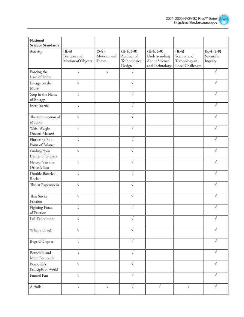
National Science Standards
Activity (K-4)Position and
Motion of Objects
(5-8)Motions and
Forces
(K-4, 5-8)Abilities of
Technological
Design
(K-4, 5-8) Understanding
About Science
and Technology
(K-4) Science and
Technology in
Local Challenges
(K-4, 5-8) Scientifi c
Inquiry
Forcing the
Issue of Force
√ √ √ √
Energy on the
Move
√ √ √
Stop in the Name
of Energy
√ √ √
Inert Inertia √ √ √
Th e Commotion of
Motion
√ √ √
Wait, Weight
Doesn’t Matter?
√ √ √
Fluttering Fun,
Point of Balance
√ √ √
Finding Your
Center of Gravity
√ √ √
Newton’s in the
Driver’s Seat
√ √ √
Double-Barreled
Rocket
√ √ √
Th rust Experiment √ √ √
Th at Sticky
Friction
√ √ √
Fighting Force
of Friction
√ √ √
Lift Experiment √ √ √
What a Drag! √ √ √
Bugs O’Copter √ √ √
Bernoulli and
More Bernoulli
√ √ √
Bernoulli’s
Principle at Work!
√ √ √
Funnel Fun √ √ √
Airfoils √ √ √ √ √ √
2004–2005 NASA SCI Files™ Serieshttp://scifiles.larc.nasa.gov1010
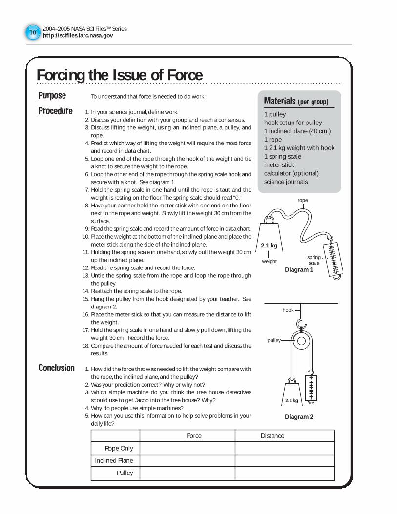
Purpose To understand that force is needed to do work
Procedure 1. In your science journal, define work.2. Discuss your definition with your group and reach a consensus.3. Discuss lifting the weight, using an inclined plane, a pulley, and
rope.4. Predict which way of lifting the weight will require the most force
and record in data chart.5. Loop one end of the rope through the hook of the weight and tie
a knot to secure the weight to the rope.6. Loop the other end of the rope through the spring scale hook and
secure with a knot. See diagram 1.7. Hold the spring scale in one hand until the rope is taut and the
weight is resting on the floor. The spring scale should read “0.”8. Have your partner hold the meter stick with one end on the floor
next to the rope and weight. Slowly lift the weight 30 cm from thesurface.
9. Read the spring scale and record the amount of force in data chart.10. Place the weight at the bottom of the inclined plane and place the
meter stick along the side of the inclined plane.11. Holding the spring scale in one hand, slowly pull the weight 30 cm
up the inclined plane.12. Read the spring scale and record the force.13. Untie the spring scale from the rope and loop the rope through
the pulley.14. Reattach the spring scale to the rope.15. Hang the pulley from the hook designated by your teacher. See
diagram 2.16. Place the meter stick so that you can measure the distance to lift
the weight.17. Hold the spring scale in one hand and slowly pull down, lifting the
weight 30 cm. Record the force.18. Compare the amount of force needed for each test and discuss the
results.
Conclusion 1. How did the force that was needed to lift the weight compare withthe rope, the inclined plane, and the pulley?
2. Was your prediction correct? Why or why not?3. Which simple machine do you think the tree house detectives
should use to get Jacob into the tree house? Why?4. Why do people use simple machines?5. How can you use this information to help solve problems in your
daily life?
Materials (per group)
1 pulley hook setup for pulley1 inclined plane (40 cm )1 rope 1 2.1 kg weight with hook1 spring scale meter stickcalculator (optional)science journals
Forcing the Issue of Force
Force Distance
Rope Only
Inclined Plane
Pulley
Diagram 1
Diagram 2
2.1 kg
2.1 kg
rope
weightspringscale
hook
pulley
Forcing the Issue of Force
2004–2005 NASA SCI Files™ Serieshttp://scifiles.larc.nasa.gov
11
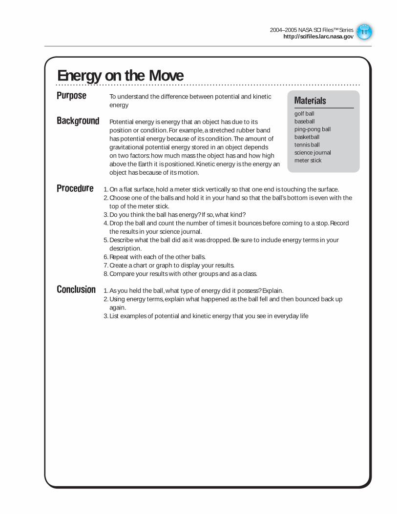
Purpose To understand the difference between potential and kinetic energy
Background Potential energy is energy that an object has due to its position or condition. For example, a stretched rubber band has potential energy because of its condition. The amount of gravitational potential energy stored in an object depends on two factors: how much mass the object has and how high above the Earth it is positioned. Kinetic energy is the energy an object has because of its motion.
Procedure 1. On a flat surface, hold a meter stick vertically so that one end is touching the surface. 2. Choose one of the balls and hold it in your hand so that the ball’s bottom is even with the
top of the meter stick. 3. Do you think the ball has energy? If so, what kind? 4. Drop the ball and count the number of times it bounces before coming to a stop. Record
the results in your science journal. 5. Describe what the ball did as it was dropped. Be sure to include energy terms in your
description. 6. Repeat with each of the other balls. 7. Create a chart or graph to display your results. 8. Compare your results with other groups and as a class.
Conclusion 1. As you held the ball, what type of energy did it possess? Explain. 2. Using energy terms, explain what happened as the ball fell and then bounced back up
again. 3. List examples of potential and kinetic energy that you see in everyday life
Energy on the MoveMaterials
golf ballbaseballping-pong ballbasketballtennis ballscience journalmeter stick
2004–2005 NASA SCI Files™ Serieshttp://scifiles.larc.nasa.gov1212
Stop in the Name of Energy!Purpose To understand the difference between kinetic and potential energy
To understand friction
Procedure 1. In your science journal, writedefinitions for potential energy,kinetic energy, and friction.
2. Discuss your definitions with yourgroup and reach a consensus foreach term.
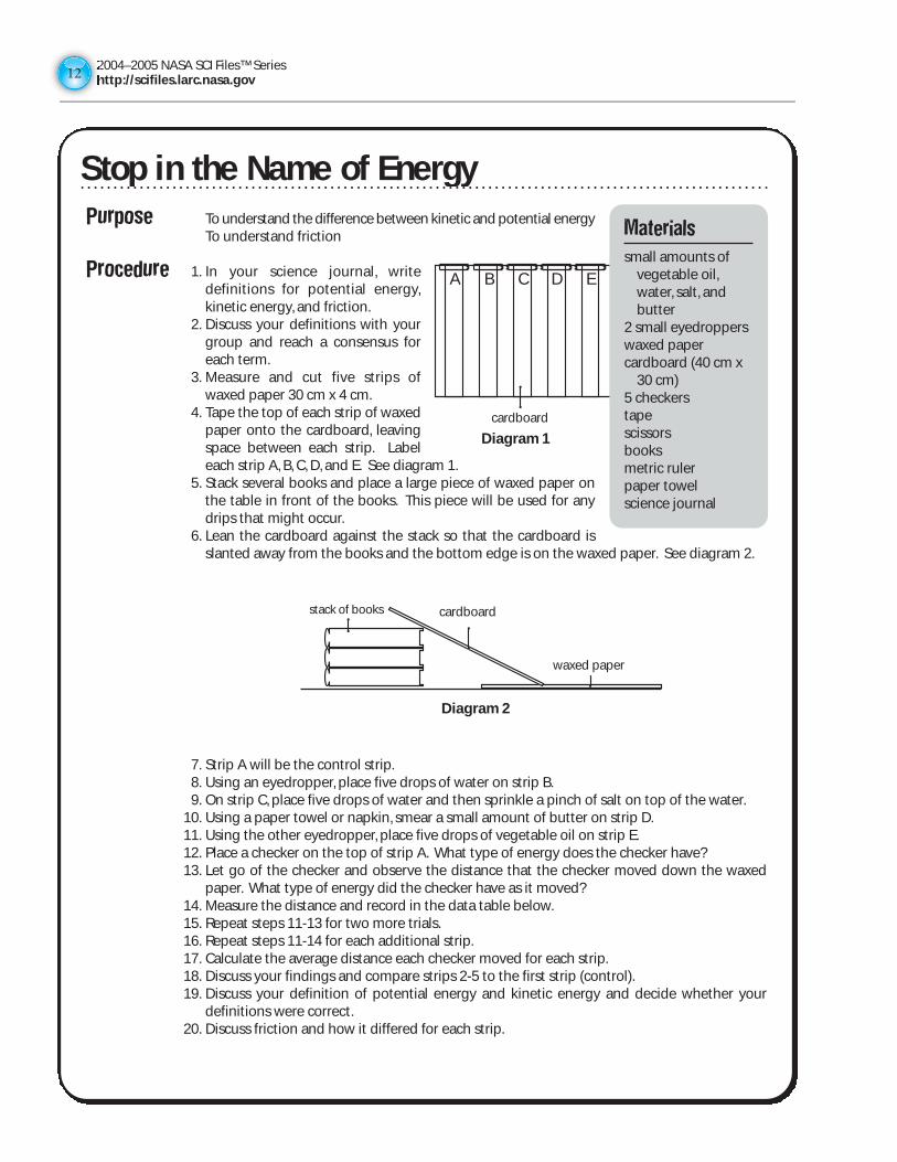
3. Measure and cut five strips ofwaxed paper 30 cm x 4 cm.
4. Tape the top of each strip of waxedpaper onto the cardboard, leavingspace between each strip. Labeleach strip A, B, C, D, and E. See diagram 1.
5. Stack several books and place a large piece of waxed paper onthe table in front of the books. This piece will be used for anydrips that might occur.
6. Lean the cardboard against the stack so that the cardboard isslanted away from the books and the bottom edge is on the waxed paper. See diagram 2.
7. Strip A will be the control strip.8. Using an eyedropper, place five drops of water on strip B.9. On strip C, place five drops of water and then sprinkle a pinch of salt on top of the water.
10. Using a paper towel or napkin, smear a small amount of butter on strip D.11. Using the other eyedropper, place five drops of vegetable oil on strip E.12. Place a checker on the top of strip A. What type of energy does the checker have?13. Let go of the checker and observe the distance that the checker moved down the waxed
paper. What type of energy did the checker have as it moved?14. Measure the distance and record in the data table below.15. Repeat steps 11-13 for two more trials.16. Repeat steps 11-14 for each additional strip.17. Calculate the average distance each checker moved for each strip.18. Discuss your findings and compare strips 2-5 to the first strip (control).19. Discuss your definition of potential energy and kinetic energy and decide whether your
definitions were correct.20. Discuss friction and how it differed for each strip.
Diagram 1
card board
A B C D E
Materials
small amounts ofvegetable oil,water, salt, andbutter
2 small eyedropperswaxed papercardboard (40 cm x
30 cm)5 checkerstapescissorsbooksmetric rulerpaper towelscience journal
stack of books
Diagram 2
card board
wax paper
cardboard
cardboard
waxed paper
Stop in the Name of Energy
2004–2005 NASA SCI Files™ Serieshttp://scifiles.larc.nasa.gov
13
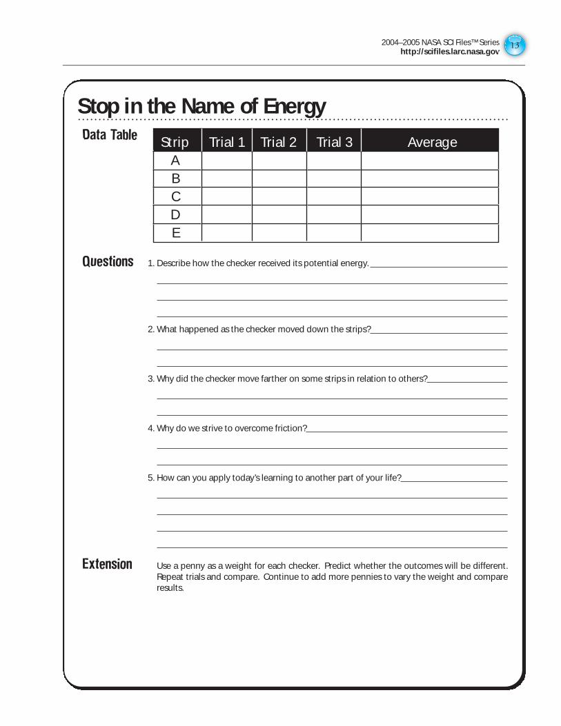
Stop in the Name of Energy!Data Table
Questions 1. Describe how the checker received its potential energy.
2. What happened as the checker moved down the strips?
3. Why did the checker move farther on some strips in relation to others?
4. Why do we strive to overcome friction?
5. How can you apply today’s learning to another part of your life?
Extension Use a penny as a weight for each checker. Predict whether the outcomes will be different.Repeat trials and compare. Continue to add more pennies to vary the weight and compareresults.
Strip Trial 1 Trial 2 Trial 3 AverageA
B C D E
Stop in the Name of Energy
2004–2005 NASA SCI Files™ Serieshttp://scifiles.larc.nasa.gov1414
Inert InertiaPurpose To understand the basic concept of inertia
Background Sir Isaac Newton was an English physicist and mathematicianwho studied the properties of force and motion. He developedthree laws of motion known as Newton’s Laws. Newton’s FirstLaw of Motion states that an object at rest will remain at rest,and an object in motion will remain in motion at a constantvelocity unless an unbalanced force acts upon it. This tendencyof objects to either remain at rest or in motion is called inertia.
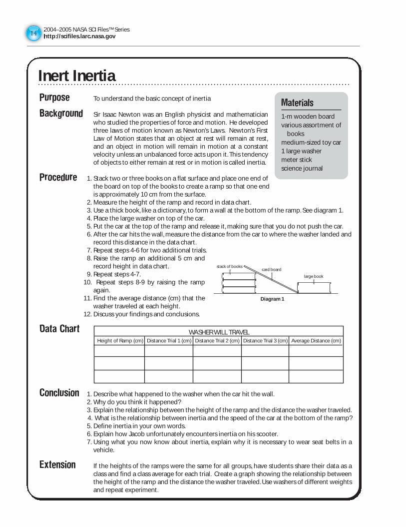
Procedure 1. Stack two or three books on a flat surface and place one end ofthe board on top of the books to create a ramp so that one endis approximately 10 cm from the surface.
2. Measure the height of the ramp and record in data chart.3. Use a thick book, like a dictionary, to form a wall at the bottom of the ramp. See diagram 1.4. Place the large washer on top of the car.5. Put the car at the top of the ramp and release it, making sure that you do not push the car.6. After the car hits the wall, measure the distance from the car to where the washer landed and
record this distance in the data chart.7. Repeat steps 4-6 for two additional trials.8. Raise the ramp an additional 5 cm and
record height in data chart.9. Repeat steps 4-7.
10. Repeat steps 8-9 by raising the rampagain.
11. Find the average distance (cm) that thewasher traveled at each height.
12. Discuss your findings and conclusions.
Data Chart
Conclusion 1. Describe what happened to the washer when the car hit the wall.2. Why do you think it happened?3. Explain the relationship between the height of the ramp and the distance the washer traveled.4. What is the relationship between inertia and the speed of the car at the bottom of the ramp?5. Define inertia in your own words.6. Explain how Jacob unfortunately encounters inertia on his scooter.7. Using what you now know about inertia, explain why it is necessary to wear seat belts in a
vehicle.
Extension If the heights of the ramps were the same for all groups, have students share their data as aclass and find a class average for each trial. Create a graph showing the relationship betweenthe height of the ramp and the distance the washer traveled. Use washers of different weightsand repeat experiment.
Materials
1-m wooden board various assortment of
booksmedium-sized toy car1 large washermeter stickscience journal
WASHER WILL TRAVELHeight of Ramp (cm) Distance Trial 1 (cm) Distance Trial 2 (cm) Distance Trial 3 (cm) Average Distance (cm)
stack of books
large book
card board
Diagram 1
Inert Inertia
2004–2005 NASA SCI Files™ Serieshttp://scifiles.larc.nasa.gov
15
The Commotion of MotionPurpose To learn about Newton’s first law of motion, which states
that an object at rest will remain at rest, and an object inmotion will remain in motion at constant velocity unless anunbalanced force acts upon it.
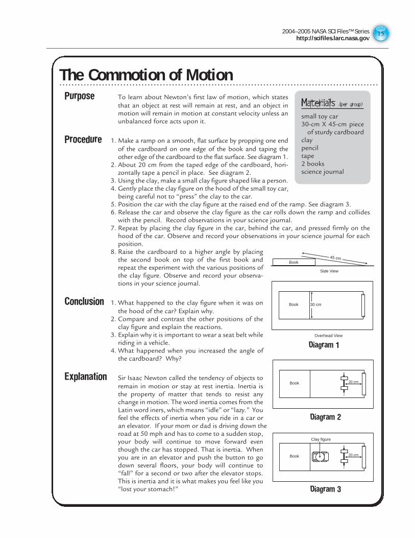
Procedure 1. Make a ramp on a smooth, flat surface by propping one endof the cardboard on one edge of the book and taping theother edge of the cardboard to the flat surface. See diagram 1.
2. About 20 cm from the taped edge of the cardboard, hori-zontally tape a pencil in place. See diagram 2.
3. Using the clay, make a small clay figure shaped like a person.4. Gently place the clay figure on the hood of the small toy car,
being careful not to “press” the clay to the car.5. Position the car with the clay figure at the raised end of the ramp. See diagram 3.6. Release the car and observe the clay figure as the car rolls down the ramp and collides
with the pencil. Record observations in your science journal.7. Repeat by placing the clay figure in the car, behind the car, and pressed firmly on the
hood of the car. Observe and record your observations in your science journal for eachposition.
8. Raise the cardboard to a higher angle by placingthe second book on top of the first book andrepeat the experiment with the various positions ofthe clay figure. Observe and record your observa-tions in your science journal.
Conclusion 1. What happened to the clay figure when it was onthe hood of the car? Explain why.
2. Compare and contrast the other positions of theclay figure and explain the reactions.
3. Explain why it is important to wear a seat belt whileriding in a vehicle.
4. What happened when you increased the angle ofthe cardboard? Why?
Explanation Sir Isaac Newton called the tendency of objects toremain in motion or stay at rest inertia. Inertia isthe property of matter that tends to resist anychange in motion. The word inertia comes from theLatin word iners, which means “idle” or “lazy.” Youfeel the effects of inertia when you ride in a car oran elevator. If your mom or dad is driving down theroad at 50 mph and has to come to a sudden stop,your body will continue to move forward eventhough the car has stopped. That is inertia. Whenyou are in an elevator and push the button to godown several floors, your body will continue to“fall” for a second or two after the elevator stops.This is inertia and it is what makes you feel like you“lost your stomach!”
Materials (per group)
small toy car30-cm X 45-cm piece
of sturdy cardboardclaypenciltape2 booksscience journal
Book
Side View
Overhead View
45 cm
Book 30 cm
Diagram 1
Book 20 cm
Diagram 2
Book
Clay figure
20 cm
Diagram 3
The Commotion of Motion
2004–2005 NASA SCI Files™ Serieshttp://scifiles.larc.nasa.gov1616
Wait, Weight Doesn’t Matter?Purpose To learn that gravity pulls all objects towards the center of the Earth
To learn that air resistance can change the speed in which objects willfall
Procedure 1. Take a coin and trace it onto the paper.2. Cut out the circle, making sure that the paper circle is not bigger than
the coin.3. Predict what will happen if you drop the coin from one hand and the
paper coin from the other. Record your prediction in your sciencejournal.
4. Place the coin in one hand and the paper coin in the other. Drop themboth at the same time. Record your results.
5. To further enforce the idea that all objects are going to drop at the same rate, try the nextactivity.
6. Stack 3 coins on top of each other and tape together.7. Place one coin on the edge of the table and place the stack of coins on the edge also, but 5
cm apart from the single coin.8. Place a ruler behind the coins so that the ruler is touching them.9. Make a prediction as to what is going to happen when you push the ruler and make the coins
fall off the table.10. Using the ruler, push the coins off the table at the same time. Observe and record your
observations in your science journal.11. Discuss your results with your team partner and class.
Conclusion 1. When the coin and paper coin were dropped separately, what happened and why?2. In the experiment with the single coin and stack of coins, what happened and why?3. If gravity is always pulling you down, how does it help you?4. How would life be different if we had less gravity or no gravity at all?5. Would a bowling ball and a pebble fall at the same speed and hit the ground at the same
time if dropped from a high building?6. NASA astronauts on the Moon dropped a feather and a hammer. Which one do you think hit
the moon surface first and why?
Extension Research terminal velocity to find out more about how gravity affects objects as they fall.
Materials4 coinsthick papermetric rulerscissorspencilscience journal
Wait, Weight Doesn’t Matter?
2004–2005 NASA SCI Files™ Serieshttp://scifiles.larc.nasa.gov
17
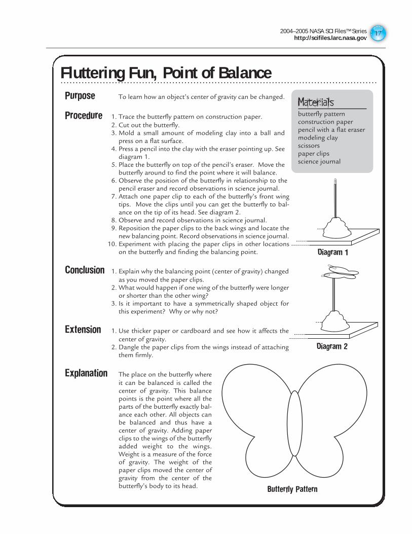
Purpose To learn how an object’s center of gravity can be changed.
Procedure 1. Trace the butterfly pattern on construction paper.2. Cut out the butterfly.3. Mold a small amount of modeling clay into a ball and
press on a flat surface.4. Press a pencil into the clay with the eraser pointing up. See
diagram 1.5. Place the butterfly on top of the pencil’s eraser. Move the
butterfly around to find the point where it will balance.6. Observe the position of the butterfly in relationship to the
pencil eraser and record observations in science journal.7. Attach one paper clip to each of the butterfly’s front wing
tips. Move the clips until you can get the butterfly to bal-ance on the tip of its head. See diagram 2.
8. Observe and record observations in science journal.9. Reposition the paper clips to the back wings and locate the
new balancing point. Record observations in science journal.10. Experiment with placing the paper clips in other locations
on the butterfly and finding the balancing point.
Conclusion 1. Explain why the balancing point (center of gravity) changedas you moved the paper clips.
2. What would happen if one wing of the butterfly were longeror shorter than the other wing?
3. Is it important to have a symmetrically shaped object forthis experiment? Why or why not?
Extension 1. Use thicker paper or cardboard and see how it affects thecenter of gravity.
2. Dangle the paper clips from the wings instead of attachingthem firmly.
Explanation The place on the butterfly whereit can be balanced is called thecenter of gravity. This balancepoints is the point where all theparts of the butterfly exactly bal-ance each other. All objects canbe balanced and thus have acenter of gravity. Adding paperclips to the wings of the butterflyadded weight to the wings.Weight is a measure of the forceof gravity. The weight of thepaper clips moved the center ofgravity from the center of thebutterfly’s body to its head.
Fluttering Fun, Point of Balance
Materialsbutterfly patternconstruction paperpencil with a flat erasermodeling clayscissorspaper clipsscience journal
Diagram 1
Diagram 2
Butterfly Pattern
Fluttering Fun, Point of Balance
2004–2005 NASA SCI Files™ Serieshttp://scifiles.larc.nasa.gov1818
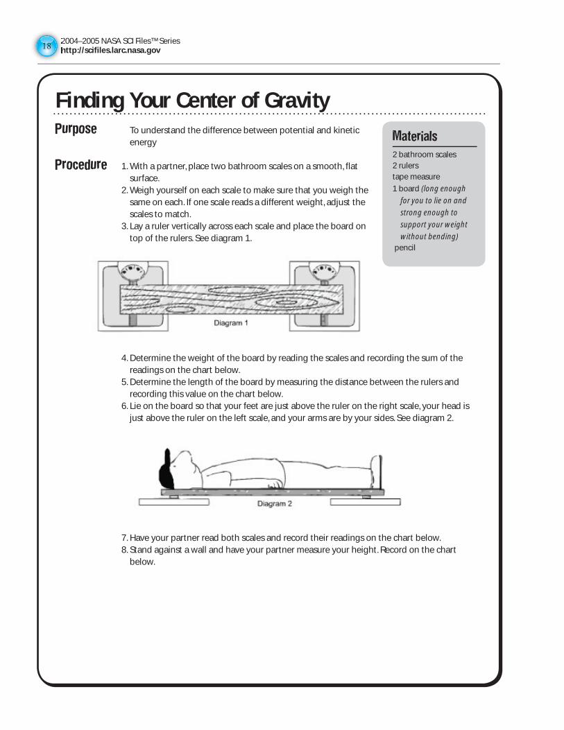
Purpose To understand the difference between potential and kinetic energy
Procedure 1. With a partner, place two bathroom scales on a smooth, flat surface.
2. Weigh yourself on each scale to make sure that you weigh the same on each. If one scale reads a different weight, adjust the scales to match.
3. Lay a ruler vertically across each scale and place the board on top of the rulers. See diagram 1.
4. Determine the weight of the board by reading the scales and recording the sum of the readings on the chart below.
5. Determine the length of the board by measuring the distance between the rulers and recording this value on the chart below.
6. Lie on the board so that your feet are just above the ruler on the right scale, your head is just above the ruler on the left scale, and your arms are by your sides. See diagram 2.
7. Have your partner read both scales and record their readings on the chart below. 8. Stand against a wall and have your partner measure your height. Record on the chart
below.
Finding Your Center of GravityMaterials
2 bathroom scales2 rulerstape measure
1 board (long enough
for you to lie on and
strong enough to
support your weight
without bending) pencil
2004–2005 NASA SCI Files™ Serieshttp://scifiles.larc.nasa.gov
19
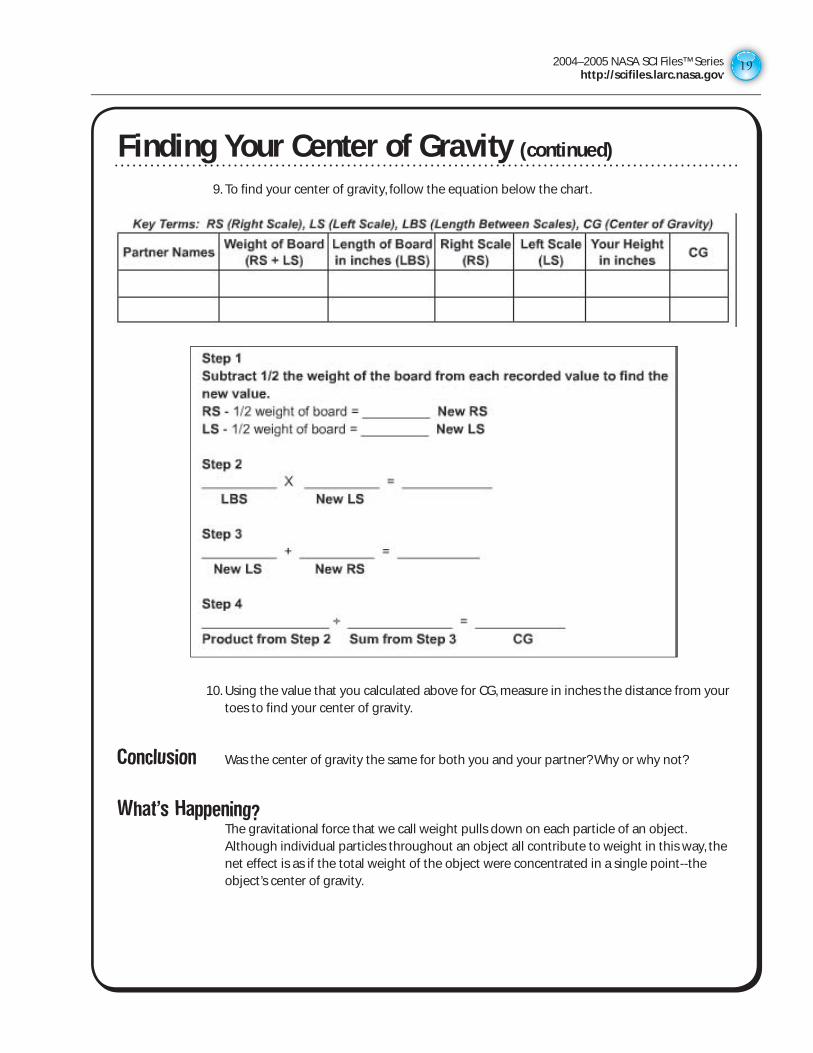
9. To find your center of gravity, follow the equation below the chart.
10. Using the value that you calculated above for CG, measure in inches the distance from your toes to find your center of gravity.
Conclusion Was the center of gravity the same for both you and your partner? Why or why not?
What’s Happening? The gravitational force that we call weight pulls down on each particle of an object.
Although individual particles throughout an object all contribute to weight in this way, the net effect is as if the total weight of the object were concentrated in a single point--the object’s center of gravity.
Finding Your Center of Gravity (continued)
2004–2005 NASA SCI Files™ Serieshttp://scifiles.larc.nasa.gov2020
Purpose To learn about Newton’s Third Law of Motion: For every action there is an equal and opposite reaction
Background Potential energy is energy that an object has due to its position or condition. For example, a stretched rubber band has potential energy because of its condition. The amount of gravitational potential energy stored in an object depends on two factors: how much mass the object has and how high above the Earth it is positioned. Kinetic energy is the energy an object has because of its motion.
Procedure 1. Working in pairs, on a clean, smooth, flat surface, place cars 60 cm apart so they are directly facing each other.
2. Each student will gently push his/her car towards the other car at a designated time indicated by a countdown of 3-2-1, go.
3. Observe and note the point on the surface where the cars made contact, and once the cars come to a stop, mark that point, being careful not to move the cars.
4. Measure the distance each car traveled from the point marked and record in your science journal.
5. Repeat for at least three more trials. 6. In your science journal, write a description of what happened as the cars were pushed,
made contact, and finally stopped.
Conclusion 1. What happened after the cars made contact? 2. Explain why it happened. 3. What would happen if you applied a greater force when pushing the cars?
Extension 1. Apply different forces to the car and compare the results. 2. Add various amounts of weight (pennies or washers) to the cars and compare what
happens.
Newton’s in the Driver’s SeatMaterials
2 identical plastic toy cars
metric rulersmooth, flat surfacescience journalpencil
2004–2005 NASA SCI Files™ Serieshttp://scifiles.larc.nasa.gov
21
Purpose The purpose of this activity is to build a simple rocket and put Newton’s third law (For every action there is an equal and opposite reaction) to the test.
Background Potential energy is energy that an object has due to its position or condition. For example, a stretched rubber band has potential energy because of its condition. The amount of gravitational potential energy stored in an object depends on two factors: how much mass the object has and how high above the Earth it is positioned. Kinetic energy is the energy an object has because of its motion.
Procedure 1. Check the bottle for any cracks or damage. The bottle must be damage free! 2. Take off the soft drink label and place it in the trash. 3. Place a ball of modeling clay around one end of the smaller straw. Do not poke the straw
through the clay! The ball of modeling clay needs to be large enough to cover the mouth of the bottle.
4. Place the end of the smaller straw that has clay on it inside the mouth of the bottle to seal the mouth of the bottle.
5. Test for leaks by plugging the other end of the small straw with your finger and squeeze the bottle. The bottle should feel hard when there are no leaks. Be sure not to squeeze with crushing force!
6. Cut two strips of construction paper the length of the 22 cm by 28 cm paper; then cut each strip so that it is 2 cm thick.
7. Measure the length of one piece to be 14 cm and cut it; then measure the length of the second piece to be 7 cm and cut it.
8. Bend the two pieces of construction paper strips to form circles and tape eac one, joining either end of the paper.
9. Place the 14-cm strip of construction paper on the base of the larger straw so that it looks like it forms a hoop around the straw.
10. Do the same with the 7-cm strip of construction paper at the end of the large straw, forming a hoop.
11. Place a small ball of clay into the end of the large straw like a cork. 12. Place the larger straw over the smaller one and hold the paper loops on the top side of the
bottle rocket with another straw so that the paper loops rest on the straw for stability. 13. Give the bottle a quick squeeze and make observations. 14. Record your observations in the science journal.
Double-Barreled RocketMaterials
plastic soft drink bottlefour drinking straws
(two different sizes and thicknesses)
modeling clayconstruction paperscience journal
2004–2005 NASA SCI Files™ Serieshttp://scifiles.larc.nasa.gov2222
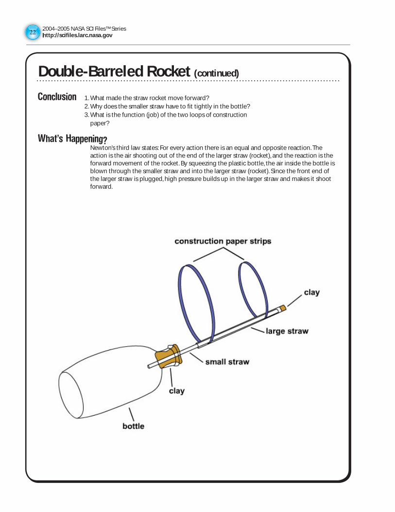
Conclusion 1. What made the straw rocket move forward? 2. Why does the smaller straw have to fit tightly in the bottle? 3. What is the function (job) of the two loops of construction
paper?
What’s Happening? Newton’s third law states: For every action there is an equal and opposite reaction. The
action is the air shooting out of the end of the larger straw (rocket), and the reaction is the forward movement of the rocket. By squeezing the plastic bottle, the air inside the bottle is blown through the smaller straw and into the larger straw (rocket). Since the front end of the larger straw is plugged, high pressure builds up in the larger straw and makes it shoot forward.
Double-Barreled Rocket (continued)
2004–2005 NASA SCI Files™ Serieshttp://scifiles.larc.nasa.gov
23
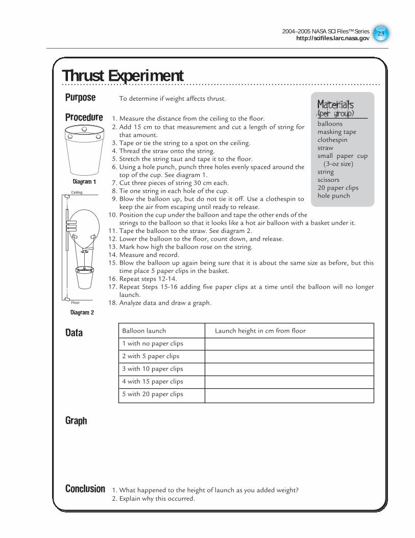
Thrust ExperimentPurpose To determine if weight affects thrust.
Procedure 1. Measure the distance from the ceiling to the floor.2. Add 15 cm to that measurement and cut a length of string for
that amount.3. Tape or tie the string to a spot on the ceiling.4. Thread the straw onto the string.5. Stretch the string taut and tape it to the floor.6. Using a hole punch, punch three holes evenly spaced around the
top of the cup. See diagram 1.7. Cut three pieces of string 30 cm each.8. Tie one string in each hole of the cup.9. Blow the balloon up, but do not tie it off. Use a clothespin to
keep the air from escaping until ready to release.10. Position the cup under the balloon and tape the other ends of the
strings to the balloon so that it looks like a hot air balloon with a basket under it.11. Tape the balloon to the straw. See diagram 2.12. Lower the balloon to the floor, count down, and release.13. Mark how high the balloon rose on the string.14. Measure and record.15. Blow the balloon up again being sure that it is about the same size as before, but this
time place 5 paper clips in the basket.16. Repeat steps 12-14.17. Repeat Steps 15-16 adding five paper clips at a time until the balloon will no longer
launch.18. Analyze data and draw a graph.
Data
Graph
Conclusion 1. What happened to the height of launch as you added weight?2. Explain why this occurred.
Materials(per group)balloonsmasking tapeclothespinstrawsmall paper cup
(3-oz size)stringscissors20 paper clipshole punch
Balloon launch Launch height in cm from floor
1 with no paper clips
2 with 5 paper clips
3 with 10 paper clips
4 with 15 paper clips
5 with 20 paper clips
Diagram 1
Floor
Ceiling
Diagram 2
Thrust Experiment
2004–2005 NASA SCI Files™ Serieshttp://scifiles.larc.nasa.gov2424
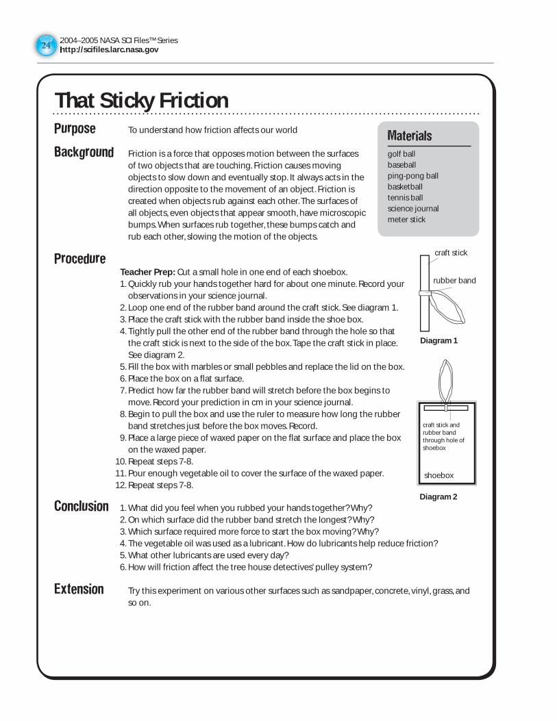
Purpose To understand how friction affects our world
Background Friction is a force that opposes motion between the surfaces of two objects that are touching. Friction causes moving objects to slow down and eventually stop. It always acts in the direction opposite to the movement of an object. Friction is created when objects rub against each other. The surfaces of all objects, even objects that appear smooth, have microscopic bumps. When surfaces rub together, these bumps catch and rub each other, slowing the motion of the objects.
Procedure Teacher Prep: Cut a small hole in one end of each shoebox. 1. Quickly rub your hands together hard for about one minute. Record your
observations in your science journal. 2. Loop one end of the rubber band around the craft stick. See diagram 1. 3. Place the craft stick with the rubber band inside the shoe box. 4. Tightly pull the other end of the rubber band through the hole so that
the craft stick is next to the side of the box. Tape the craft stick in place. See diagram 2.
5. Fill the box with marbles or small pebbles and replace the lid on the box. 6. Place the box on a flat surface. 7. Predict how far the rubber band will stretch before the box begins to
move. Record your prediction in cm in your science journal. 8. Begin to pull the box and use the ruler to measure how long the rubber
band stretches just before the box moves. Record. 9. Place a large piece of waxed paper on the flat surface and place the box
on the waxed paper. 10. Repeat steps 7-8. 11. Pour enough vegetable oil to cover the surface of the waxed paper. 12. Repeat steps 7-8.
Conclusion 1. What did you feel when you rubbed your hands together? Why? 2. On which surface did the rubber band stretch the longest? Why? 3. Which surface required more force to start the box moving? Why? 4. The vegetable oil was used as a lubricant. How do lubricants help reduce friction? 5. What other lubricants are used every day? 6. How will friction affect the tree house detectives’ pulley system?
Extension Try this experiment on various other surfaces such as sandpaper, concrete, vinyl, grass, and so on.
That Sticky FrictionMaterials
golf ballbaseballping-pong ballbasketballtennis ballscience journalmeter stick
Diagram 1
Diagram 2
shoebox
rubber band
craft stick
craft stick and rubber band through hole of shoebox
2004–2005 NASA SCI Files™ Serieshttp://scifiles.larc.nasa.gov
25
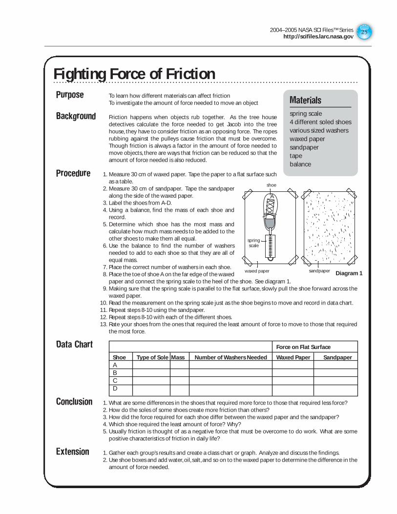
Purpose To learn how different materials can affect frictionTo investigate the amount of force needed to move an object
Background Friction happens when objects rub together. As the tree housedetectives calculate the force needed to get Jacob into the treehouse, they have to consider friction as an opposing force. The ropesrubbing against the pulleys cause friction that must be overcome.Though friction is always a factor in the amount of force needed tomove objects, there are ways that friction can be reduced so that theamount of force needed is also reduced.
Procedure 1. Measure 30 cm of waxed paper. Tape the paper to a flat surface suchas a table.
2. Measure 30 cm of sandpaper. Tape the sandpaperalong the side of the waxed paper.
3. Label the shoes from A-D.4. Using a balance, find the mass of each shoe and
record.5. Determine which shoe has the most mass and
calculate how much mass needs to be added to theother shoes to make them all equal.
6. Use the balance to find the number of washersneeded to add to each shoe so that they are all ofequal mass.
7. Place the correct number of washers in each shoe.8. Place the toe of shoe A on the far edge of the waxed
paper and connect the spring scale to the heel of the shoe. See diagram 1.9. Making sure that the spring scale is parallel to the flat surface, slowly pull the shoe forward across the
waxed paper.10. Read the measurement on the spring scale just as the shoe begins to move and record in data chart.11. Repeat steps 8-10 using the sandpaper.12. Repeat steps 8-10 with each of the different shoes.13. Rate your shoes from the ones that required the least amount of force to move to those that required
the most force.
Data Chart
Conclusion 1. What are some differences in the shoes that required more force to those that required less force?2. How do the soles of some shoes create more friction than others?3. How did the force required for each shoe differ between the waxed paper and the sandpaper?4. Which shoe required the least amount of force? Why?5. Usually friction is thought of as a negative force that must be overcome to do work. What are some
positive characteristics of friction in daily life?
Extension 1. Gather each group’s results and create a class chart or graph. Analyze and discuss the findings.2. Use shoe boxes and add water, oil, salt, and so on to the waxed paper to determine the difference in the
amount of force needed.
Fighting Force of FrictionMaterialsspring scale4 different soled shoesvarious sized washerswaxed papersandpapertapebalance
springscale
wax paper
shoe
sandpaper
Force on Flat Surface
Shoe Type of Sole Mass Number of Washers Needed Waxed Paper SandpaperABCD
A
Diagram 1waxed paper
Fighting Force of Friction
2004–2005 NASA SCI Files™ Serieshttp://scifiles.larc.nasa.gov2626
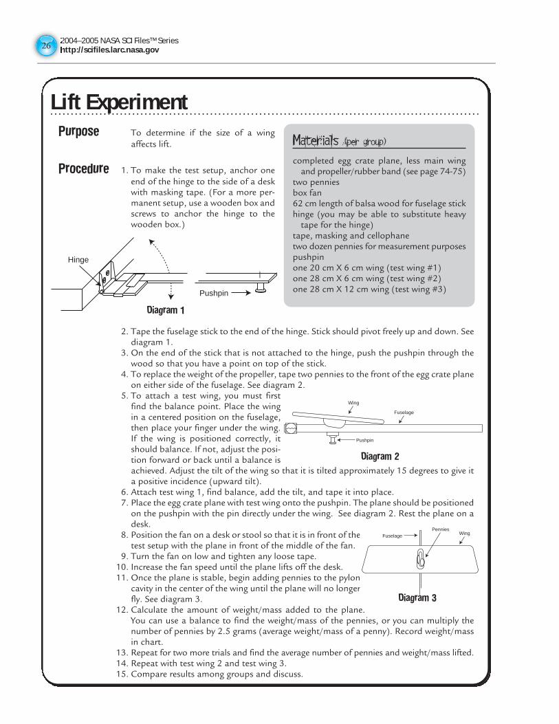
Lift ExperimentPurpose To determine if the size of a wing
affects lift.
Procedure 1. To make the test setup, anchor oneend of the hinge to the side of a deskwith masking tape. (For a more per-manent setup, use a wooden box andscrews to anchor the hinge to thewooden box.)
2. Tape the fuselage stick to the end of the hinge. Stick should pivot freely up and down. Seediagram 1.
3. On the end of the stick that is not attached to the hinge, push the pushpin through thewood so that you have a point on top of the stick.
4. To replace the weight of the propeller, tape two pennies to the front of the egg crate planeon either side of the fuselage. See diagram 2.
5. To attach a test wing, you must firstfind the balance point. Place the wingin a centered position on the fuselage,then place your finger under the wing.If the wing is positioned correctly, itshould balance. If not, adjust the posi-tion forward or back until a balance isachieved. Adjust the tilt of the wing so that it is tilted approximately 15 degrees to give ita positive incidence (upward tilt).
6. Attach test wing 1, find balance, add the tilt, and tape it into place. 7. Place the egg crate plane with test wing onto the pushpin. The plane should be positioned
on the pushpin with the pin directly under the wing. See diagram 2. Rest the plane on adesk.
8. Position the fan on a desk or stool so that it is in front of thetest setup with the plane in front of the middle of the fan.
9. Turn the fan on low and tighten any loose tape. 10. Increase the fan speed until the plane lifts off the desk. 11. Once the plane is stable, begin adding pennies to the pylon
cavity in the center of the wing until the plane will no longerfly. See diagram 3.
12. Calculate the amount of weight/mass added to the plane.You can use a balance to find the weight/mass of the pennies, or you can multiply thenumber of pennies by 2.5 grams (average weight/mass of a penny). Record weight/massin chart.
13. Repeat for two more trials and find the average number of pennies and weight/mass lifted.14. Repeat with test wing 2 and test wing 3. 15. Compare results among groups and discuss.
Materials (per group)completed egg crate plane, less main wing
and propeller/rubber band (see page 74-75)two pennies box fan62 cm length of balsa wood for fuselage stickhinge (you may be able to substitute heavy
tape for the hinge)tape, masking and cellophanetwo dozen pennies for measurement purposespushpinone 20 cm X 6 cm wing (test wing #1)one 28 cm X 6 cm wing (test wing #2)one 28 cm X 12 cm wing (test wing #3)
Hinge
Pushpin
Diagram 1
Wing
Fuselage
Pushpin
Diagram 2
PenniesWingFuselage
Diagram 3
Lift Experiment
2004–2005 NASA SCI Files™ Serieshttp://scifiles.larc.nasa.gov
27
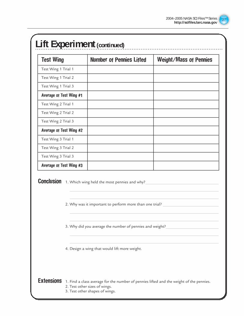
Lift Experiment (continued)
Conclusion 1. Which wing held the most pennies and why?
2. Why was it important to perform more than one trial?
3. Why did you average the number of pennies and weight?
4. Design a wing that would lift more weight.
Extensions 1. Find a class average for the number of pennies lifted and the weight of the pennies.2. Test other sizes of wings.3. Test other shapes of wings.
Test Wing Number of Pennies Lifted Weight/Mass of Pennies
Test Wing 1 Trial 1
Test Wing 1 Trial 2
Test Wing 1 Trial 3
Average of Test Wing #1
Test Wing 2 Trial 1
Test Wing 2 Trial 2
Test Wing 2 Trial 3
Average of Test Wing #2
Test Wing 3 Trial 1
Test Wing 3 Trial 2
Test Wing 3 Trial 3
Average of Test Wing #3
Lift Experiment (continued)
2004–2005 NASA SCI Files™ Serieshttp://scifiles.larc.nasa.gov2828
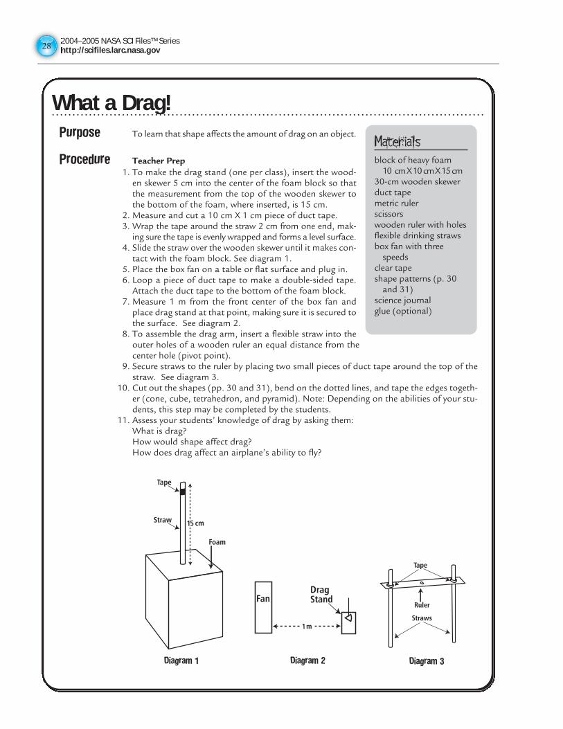
What a Drag!Purpose To learn that shape affects the amount of drag on an object.
Procedure Teacher Prep1. To make the drag stand (one per class), insert the wood-
en skewer 5 cm into the center of the foam block so thatthe measurement from the top of the wooden skewer tothe bottom of the foam, where inserted, is 15 cm.
2. Measure and cut a 10 cm X 1 cm piece of duct tape.3. Wrap the tape around the straw 2 cm from one end, mak-
ing sure the tape is evenly wrapped and forms a level surface.4. Slide the straw over the wooden skewer until it makes con-
tact with the foam block. See diagram 1.5. Place the box fan on a table or flat surface and plug in.6. Loop a piece of duct tape to make a double-sided tape.
Attach the duct tape to the bottom of the foam block.7. Measure 1 m from the front center of the box fan and
place drag stand at that point, making sure it is secured tothe surface. See diagram 2.
8. To assemble the drag arm, insert a flexible straw into theouter holes of a wooden ruler an equal distance from thecenter hole (pivot point).
9. Secure straws to the ruler by placing two small pieces of duct tape around the top of thestraw. See diagram 3.
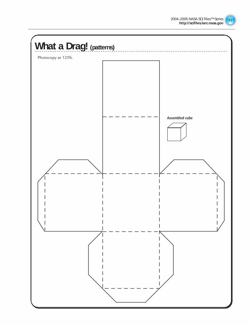
10. Cut out the shapes (pp. 30 and 31), bend on the dotted lines, and tape the edges togeth-er (cone, cube, tetrahedron, and pyramid). Note: Depending on the abilities of your stu-dents, this step may be completed by the students.
11. Assess your students’ knowledge of drag by asking them:What is drag?How would shape affect drag?How does drag affect an airplane’s ability to fly?
Materialsblock of heavy foam
10 cm X 10 cm X 15 cm30-cm wooden skewerduct tapemetric rulerscissorswooden ruler with holesflexible drinking strawsbox fan with three
speedsclear tapeshape patterns (p. 30
and 31)science journalglue (optional)
Foam
15 cm
Tape
Straw
Diagram 1
1m
DragStandFan
Diagram 2
Ruler
Tape
Straws
Diagram 3
What a Drag!
2004–2005 NASA SCI Files™ Serieshttp://scifiles.larc.nasa.gov
29
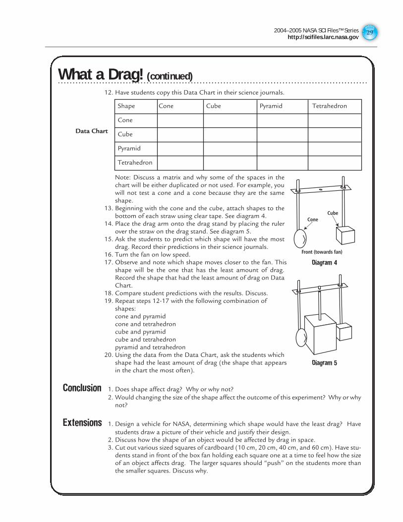
12. Have students copy this Data Chart in their science journals.
Data Chart
Note: Discuss a matrix and why some of the spaces in thechart will be either duplicated or not used. For example, youwill not test a cone and a cone because they are the sameshape.
13. Beginning with the cone and the cube, attach shapes to thebottom of each straw using clear tape. See diagram 4.
14. Place the drag arm onto the drag stand by placing the rulerover the straw on the drag stand. See diagram 5.
15. Ask the students to predict which shape will have the mostdrag. Record their predictions in their science journals.
16. Turn the fan on low speed.17. Observe and note which shape moves closer to the fan. This
shape will be the one that has the least amount of drag.Record the shape that had the least amount of drag on DataChart.
18. Compare student predictions with the results. Discuss.19. Repeat steps 12-17 with the following combination of
shapes:cone and pyramidcone and tetrahedroncube and pyramidcube and tetrahedronpyramid and tetrahedron
20. Using the data from the Data Chart, ask the students whichshape had the least amount of drag (the shape that appearsin the chart the most often).
Conclusion 1. Does shape affect drag? Why or why not?2. Would changing the size of the shape affect the outcome of this experiment? Why or why
not?
Extensions 1. Design a vehicle for NASA, determining which shape would have the least drag? Havestudents draw a picture of their vehicle and justify their design.
2. Discuss how the shape of an object would be affected by drag in space. 3. Cut out various sized squares of cardboard (10 cm, 20 cm, 40 cm, and 60 cm). Have stu-
dents stand in front of the box fan holding each square one at a time to feel how the sizeof an object affects drag. The larger squares should “push” on the students more thanthe smaller squares. Discuss why.
What a Drag! (continued)
Shape Cone Cube Pyramid Tetrahedron
Cone
Cube
Pyramid
Tetrahedron
Cone
Front (towards fan)
Cube
Diagram 4
Diagram 5
What a Drag! (continued)
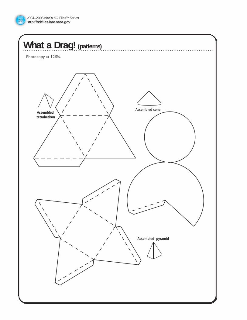
2004–2005 NASA SCI Files™ Serieshttp://scifiles.larc.nasa.gov3030
What a Drag! (patterns)
Assembled pyramid
Assembledtetrahedron
Assembled cone
Photocopy at 125%.
What a Drag! (patterns)
2004–2005 NASA SCI Files™ Serieshttp://scifiles.larc.nasa.gov
31
What a Drag! (Patterns)
Assembled cube
Photocopy at 125%.
What a Drag! (patterns)
2004–2005 NASA SCI Files™ Serieshttp://scifiles.larc.nasa.gov3232
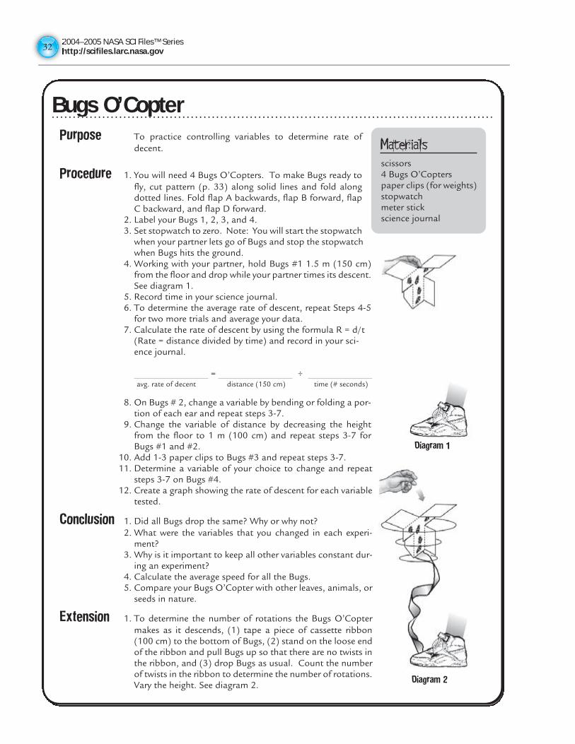
Bugs O’CopterPurpose To practice controlling variables to determine rate of
decent.
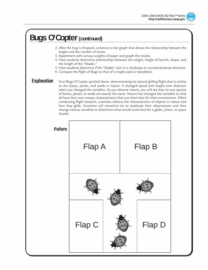
Procedure 1. You will need 4 Bugs O’Copters. To make Bugs ready tofly, cut pattern (p. 33) along solid lines and fold alongdotted lines. Fold flap A backwards, flap B forward, flapC backward, and flap D forward.
2. Label your Bugs 1, 2, 3, and 4.3. Set stopwatch to zero. Note: You will start the stopwatch
when your partner lets go of Bugs and stop the stopwatchwhen Bugs hits the ground.
4. Working with your partner, hold Bugs #1 1.5 m (150 cm)from the floor and drop while your partner times its descent.See diagram 1.
5. Record time in your science journal.6. To determine the average rate of descent, repeat Steps 4-5
for two more trials and average your data.7. Calculate the rate of descent by using the formula R = d/t
(Rate = distance divided by time) and record in your sci-ence journal.
= ÷avg. rate of decent distance (150 cm) time (# seconds)
8. On Bugs # 2, change a variable by bending or folding a por-tion of each ear and repeat steps 3-7.
9. Change the variable of distance by decreasing the heightfrom the floor to 1 m (100 cm) and repeat steps 3-7 forBugs #1 and #2.
10. Add 1-3 paper clips to Bugs #3 and repeat steps 3-7.11. Determine a variable of your choice to change and repeat
steps 3-7 on Bugs #4. 12. Create a graph showing the rate of descent for each variable
tested.
Conclusion 1. Did all Bugs drop the same? Why or why not?2. What were the variables that you changed in each experi-
ment?3. Why is it important to keep all other variables constant dur-
ing an experiment?4. Calculate the average speed for all the Bugs.5. Compare your Bugs O’Copter with other leaves, animals, or
seeds in nature.
Extension 1. To determine the number of rotations the Bugs O’Coptermakes as it descends, (1) tape a piece of cassette ribbon(100 cm) to the bottom of Bugs, (2) stand on the loose endof the ribbon and pull Bugs up so that there are no twists inthe ribbon, and (3) drop Bugs as usual. Count the numberof twists in the ribbon to determine the number of rotations.Vary the height. See diagram 2.
Materialsscissors4 Bugs O’Copterspaper clips (for weights)stopwatchmeter stickscience journal
Diagram 2
Diagram 1
Bugs O’Copter
2004–2005 NASA SCI Files™ Serieshttp://scifiles.larc.nasa.gov
33
Bugs O’Copter (continued)2. After the bug is dropped, construct a bar graph that shows the relationship between the
height and the number of twists.3. Experiment with various weights of paper and graph the results.4. Have students determine relationships between the weight, height of launch, shape, and
the length of the “blades.”5. Have students determine if the “blades” turn in a clockwise or counterclockwise direction.6. Compare the flight of Bugs to that of a maple seed or dandelion.
Explanation Your Bugs O’Copter spiraled down, demonstrating its natural gliding flight that is similarto the leaves, petals, and seeds in nature. It changed speed and maybe even directionwhen you changed the variables. As you observe nature, you will see that no two speciesof leaves, petals, or seeds are exactly the same. Nature has changed the variables so theyall have their own unique characteristics that suit them best for their environment. Whenconducting flight research, scientists observe the characteristics of objects in nature andhow they glide. Scientists will sometime try to duplicate their observations and thenchange various variables to determine what would work best for a glider, plane, or spaceshuttle.
Flap A Flap B
Flap DFlap C
Pattern
Bugs O’Copter (continued)
2004–2005 NASA SCI Files™ Serieshttp://scifiles.larc.nasa.gov3434
Bernoulli and More BernoulliTry one or more of these activities to better understand Bernoulli’s Principle.
Tent with a StrawFold a 20-cm X 13-cm piece of paper in half to make a tent. Place the paper tent on the desk. Using astraw, blow under the tent and observe what happens. Blow harder and observe what happens. Try blowinghard against the side of the tent and observe what happens.
Balloon BlowBlow up two balloons and tie off the ends. Cut two pieces of string 30 cm each. Tie one end of each stringto each balloon. Hold the balloons in front of you by the strings about 5 cm apart. Blow very hard betweenthe two balloons and observe what happens. What did the balloons do?
Ping PongPlace two ping pong balls on a table about 2 cm apart. Using a straw, blow very hard between the two ballsand observe what happens. Did the balls move closer together or farther apart?
Paper PaperHold two pieces of notebook paper in front of you about 5 cm apart. Blow hard between the papers andobserve what happens. Which way did the papers move?
Stuck to ItCut out a square of paper approximately 3 cm X 3 cm. Place the paper in the palm of your hand, and usingyour thumb and middle finger, hold a quarter (or nickel) about 1 cm above the paper. Place your mouthabove the coin and blow hard. Observes what happens.
Ball and StrawBend a flexible straw so that the short end is pointing up. Hold a ping pong ball over the opening of thestraw and blow. Let go of the ball and observe what happens. What happens if you tilt the straw?
ExplanationAir is pretty pushy stuff. It never pulls or sucks; it only pushes. Right now, air is pushing on you from everydirection. This constant push of air is called air pressure. We are so used to air being around us that wedon’t even notice it. In the 1700’s a Swiss mathematician named Daniel Bernoulli discovered that when flow-ing air or water changed its speed, its pressure also changed. In all of the experiments, the air speed wasincreased, creating a decrease in pressure. When the air pressure under the tent; between the balloons,papers, and balls; and under the paper with the coin was decreased, the air on the other sides had higherpressure. This higher pressure pressed inward, causing the tent to fall to the table and the balloons, pieces ofpaper, and ping pong balls to go together. In “Stuck to It” the air quickly moves between the paper and thecoin, creating low pressure; therefore, the air pressure below the paper is greater and “holds” it against thecoin. Now you describe what is happening with the ping-pong ball and straw.
MisconceptionsMany books state that air speeds up over a wing because it has farther to travel than air moving under thewing. This statement implies that air separates at the front of the wing and must rejoin behind the wing, butthis isn’t true. Air moving over the top of a wing speeds up so much that it arrives behind the wing soonerthan air that travels beneath the wing.
Bernoulli and More Bernoulli
2004–2005 NASA SCI Files™ Serieshttp://scifiles.larc.nasa.gov
35
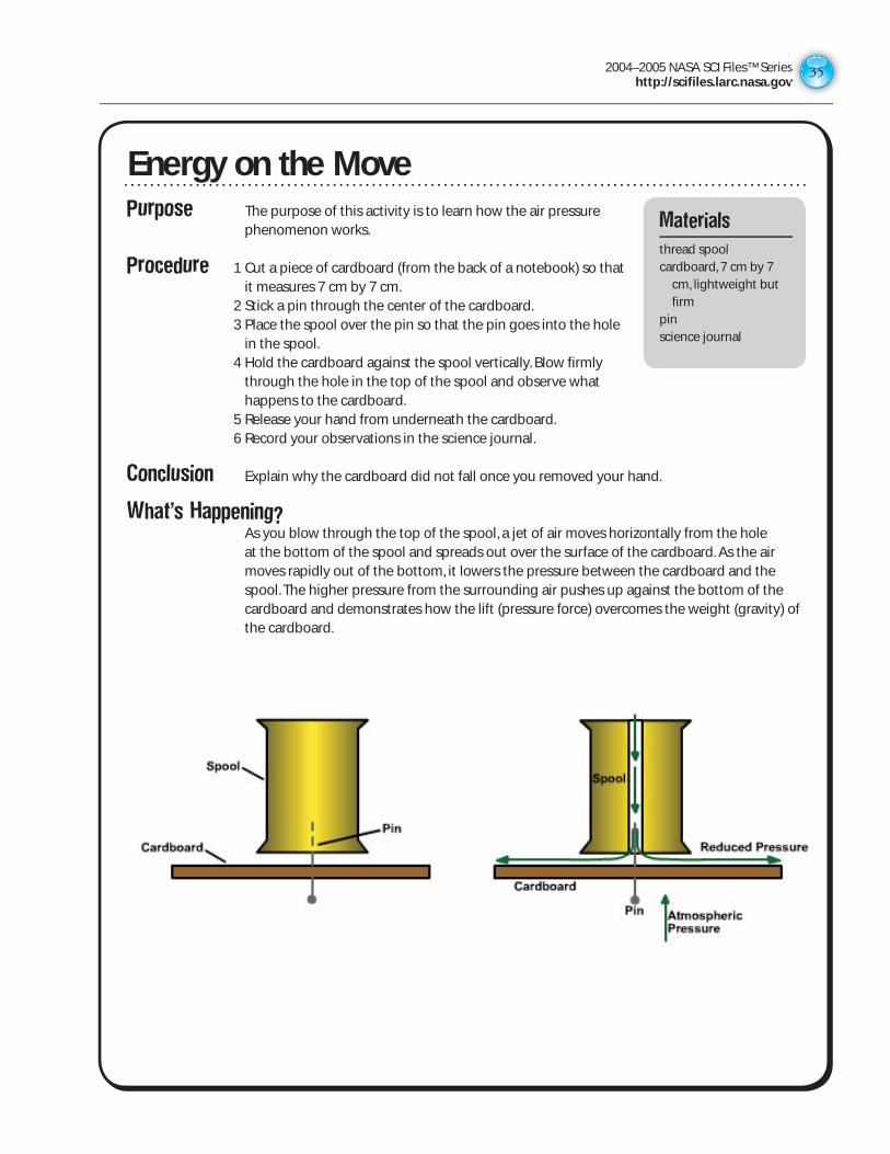
Purpose The purpose of this activity is to learn how the air pressure phenomenon works.
Procedure 1 Cut a piece of cardboard (from the back of a notebook) so that it measures 7 cm by 7 cm.
2 Stick a pin through the center of the cardboard. 3 Place the spool over the pin so that the pin goes into the hole
in the spool. 4 Hold the cardboard against the spool vertically. Blow firmly
through the hole in the top of the spool and observe what happens to the cardboard.
5 Release your hand from underneath the cardboard. 6 Record your observations in the science journal.
Conclusion Explain why the cardboard did not fall once you removed your hand.
What’s Happening? As you blow through the top of the spool, a jet of air moves horizontally from the hole
at the bottom of the spool and spreads out over the surface of the cardboard. As the air moves rapidly out of the bottom, it lowers the pressure between the cardboard and the spool. The higher pressure from the surrounding air pushes up against the bottom of the cardboard and demonstrates how the lift (pressure force) overcomes the weight (gravity) of the cardboard.
Energy on the MoveMaterials
thread spoolcardboard, 7 cm by 7
cm, lightweight but firm
pinscience journal
2004–2005 NASA SCI Files™ Serieshttp://scifiles.larc.nasa.gov3636
Purpose The purpose of this activity is to apply Bernoulli’s Principle to understand why birds, kites, and planes can fly.
Procedure 1. Bend your head back so that you will be able to blow the table tennis ball toward the ceiling.
2. Put the ball in the top of the funnel and blow hard and fast into the stem of the funnel.
3. Record in your science journal what happened to the ball. 4. Bend your head down so that you will be able to blow through the funnel straight down
toward the floor. 5. Hold the ball inside the funnel close to the hole (temporarily) and take a deep breath. 6. Let go of the ball as you blow hard through the stem of the funnel until you use all air in
your lungs. 7. Record in your science journal what happened to the table tennis ball.
What’s Happening? Bernoulli’s Principle states that when the speed of a moving fluid (air) increases, the
pressure on its edges decreases. The ball clings to the funnel when it is pointed toward the ceiling when the air is blown hard and fast through the stem of the funnel. Still air exerts more pressure around the ball than that around a stream of moving air. The ball clings to the funnel when it is pointed toward the floor because the air moves away from it faster, creating a low-pressure area in the center.
Extension Fill a cardboard box with shipping popcorn (polystyrene particles). Get a vacuum hose and place one end in the box containing the shipping popcorn. Spin the opposite end of the vacuum hose in a circular motion. As you increase the speed of the end of the vacuum hose, the air pressure will drop, and pieces of shipping popcorn will come out. The vacuum hose appears to be sucking up the shipping popcorn. That is Bernoulli’s Principle at work!
Funnel FunMaterials
1 clean funnel with a narrow opening of 1cm or less
1 tennis ballscience journal
2004–2005 NASA SCI Files™ Serieshttp://scifiles.larc.nasa.gov
37
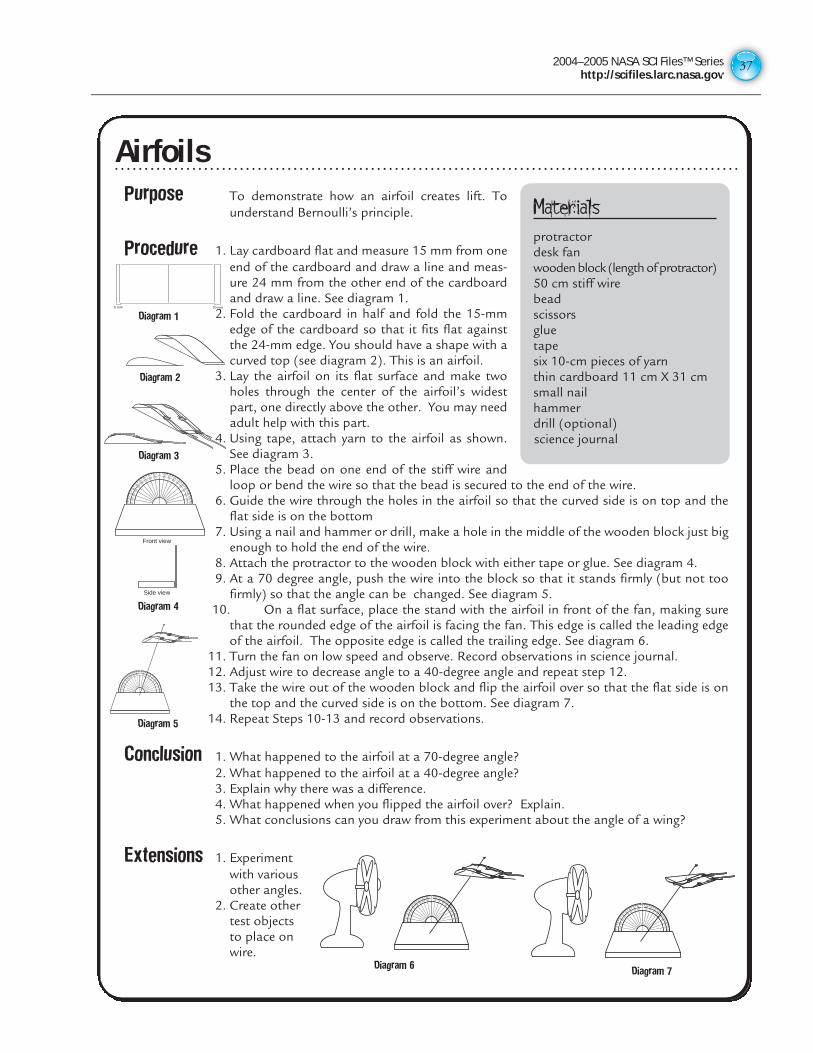
AirfoilsPurpose To demonstrate how an airfoil creates lift. To
understand Bernoulli’s principle.
Procedure 1. Lay cardboard flat and measure 15 mm from oneend of the cardboard and draw a line and meas-ure 24 mm from the other end of the cardboardand draw a line. See diagram 1.
2. Fold the cardboard in half and fold the 15-mmedge of the cardboard so that it fits flat againstthe 24-mm edge. You should have a shape with acurved top (see diagram 2). This is an airfoil.
3. Lay the airfoil on its flat surface and make twoholes through the center of the airfoil’s widestpart, one directly above the other. You may needadult help with this part.
4. Using tape, attach yarn to the airfoil as shown.See diagram 3.
5. Place the bead on one end of the stiff wire andloop or bend the wire so that the bead is secured to the end of the wire.
6. Guide the wire through the holes in the airfoil so that the curved side is on top and theflat side is on the bottom
7. Using a nail and hammer or drill, make a hole in the middle of the wooden block just bigenough to hold the end of the wire.
8. Attach the protractor to the wooden block with either tape or glue. See diagram 4.9. At a 70 degree angle, push the wire into the block so that it stands firmly (but not too
firmly) so that the angle can be changed. See diagram 5.10. On a flat surface, place the stand with the airfoil in front of the fan, making sure
that the rounded edge of the airfoil is facing the fan. This edge is called the leading edgeof the airfoil. The opposite edge is called the trailing edge. See diagram 6.
11. Turn the fan on low speed and observe. Record observations in science journal.12. Adjust wire to decrease angle to a 40-degree angle and repeat step 12.13. Take the wire out of the wooden block and flip the airfoil over so that the flat side is on
the top and the curved side is on the bottom. See diagram 7.14. Repeat Steps 10-13 and record observations.
Conclusion 1. What happened to the airfoil at a 70-degree angle?2. What happened to the airfoil at a 40-degree angle?3. Explain why there was a difference.4. What happened when you flipped the airfoil over? Explain.5. What conclusions can you draw from this experiment about the angle of a wing?
Extensions 1. Experimentwith variousother angles.
2. Create othertest objectsto place onwire.
Materialsprotractordesk fanwooden block (length of protractor)50 cm stiff wirebeadscissorsgluetapesix 10-cm pieces of yarnthin cardboard 11 cm X 31 cmsmall nailhammerdrill (optional)science journal
5 mm 20 mm
Diagram 1
Diagram 2
Diagram 3
Front view
Side view
90
270
80
100
260
280
70
110
250
290
60
120
240
300
50
130
230
310
4014
0
220320
3015
0
210330
2016
0
200340
10 170
190350
0 180 1800
350
190
170
10
340 200
16020
330 21
0
15030
320 22
0
14040
310 230
13050
300240
12060
290250
11070
280260
10080
Diagram 4
90
270
80
100
260
280
70
110
250
290
60
120
240
300
50
130
230
310
4014
0
220320
3015
0
210330
2016
0
200340
10 170
190350
0 180 1800
350
190
170
10
340 200
16020
330 21
0
15030
320 22
0
14040
310 230
13050
300240
12060
290250
11070
280260
10080
Diagram 5
90
270
80
100
260
280
70
110
250
290
60
120
240
300
50
130
230
310
4014
0
220320
3015
0
210330
2016
0
200340
10 170
190350
0 180 1800
350
190
170
10
340 200
16020
330 21
0
15030
320 22
0
14040
310 230
13050
300240
12060
290250
11070
280260
10080
Diagram 6
90
270
80
100
260
280
70
110
250
290
60
120
240
300
50
130
230
310
4014
0
220320
3015
0
210330
2016
0
200340
10 170
190350
0 180 1800
350
190
170
10
340 200
16020
330 21
0
15030
320 22
0
14040
310 230
13050
300240
12060
290250
11070
280260
10080
Diagram 7
Airfoils
2004–2005 NASA SCI Files™ Serieshttp://scifiles.larc.nasa.gov3838
ANSWER KEY
Forcing the Force
1. The students should have discovered that the inclined plane required less force to lift the weight. The pulley only used one string and that is the same as lifting the weight without a pulley. If additional pulleys and strings are used then the force would reduce.
2. Answers will vary.
3. Answers will vary. Students will probably say the inclined plane because this experiment concluded that the inclined plane took less force to lift the weight.
4. Answers will vary but should include that simple machines make “work” easier.
5. Answers will vary.
Energy on the Move
1. The ball had potential energy or stored energy. It gained potential energy when it was lifted.
2. As you let go of the ball, the potential energy started to change into the energy of motion or kinetic energy. The energy that was stored in the ball is released. When the ball hits the floor, all the potential energy changes into kinetic energy; then, when it bounces up again, the kinetic energy changes back into potential energy.
3. Answers will vary, but might include a parked car, a batter holding a bat, a rock at the top of a cliff, a moving car, a rubber band snapping back into position, and so on.
Stop in the Name of Energy!
1. The checker received its potential energy from the person placing it at the top of each strip.
2. Answers will vary.
3. The amount of friction was stronger on some strips.
4. We strive to overcome friction so machines can become more efficient.
5. Answers will vary, but should include answers such as oil for engines, bike gears, driving on wet roads, and so on.
Inert Inertia
1. The washer continues to move in a forward motion.
2. Both the toy car and the washer were put into motion because of the ramp (force of gravity). According to Newton’s First Law, objects that are in motion stay in motion. However, the car was acted upon by another force, the book wall, and therefore stopped. The washer was also in motion and continued its motion because it was not attached to the car.
3. The higher the ramp, the faster the car would move and the farther the washer would travel after the car struck the wall.
4. Same as above.
5. Answers may vary.
6. Jacob’s scooter stops when it hits the curb, but he continues to move and flies through the air.
7. Answer will vary.
The Commotion of Motion
1. The clay figure kept going forward when the toy car was forced to stop because the pencil blocked its path. Since the clay figure was not secured to the car, the clay figure continued in motion even though the car stopped. This is inertia.
2. If the clay figure is secured in or on the car, it will stop with the car. Depending on the size of the car and the figure, the figure may move forward a small amount even though it is secured.
3. It is important to wear a seat belt while riding in a car so that your body does not continue to move forward and into the windshield if the car should have to come to a sudden stop.
4. When the angle of the cardboard was increased, the speed of the car was increased. This increase in speed caused the clay figure to fly even farther. The greater the speed, the greater the inertia.
Wait,Weight Doesn’t Matter?
1. The coin hit the floor before the paper coin. As the paper coin fell, air resistance opposed its downward motion, so it moved more slowly.
2. The single coin hit the floor at the same time as the stack of three coins. Even though the stack of coins was heavier, it did not hit the floor first because the single coin had enough weight to overcome the small amount of air resistance.
3. Gravity is the force that keeps you and other objects on the ground. If it weren’t for gravity,we would have a difficult time staying in one place!
4. If there were less gravity,we would weigh less and be able to jump higher.Depending on how much gravity there was,we might even need to be weighted down so as not to float away. If there were not any gravity,we would float around like astronauts do in space.
5. Regardless of their masses, objects accelerate at the same rate. The acceleration of a falling object is due to the force of gravity between the object and the Earth. So if a pebble and a bowling ball were dropped at the same time from the same height, they would hit the ground at the same time.
6. When the astronauts dropped the feather and the hammer on the Moon, they proved that Galileo was correct in his description of the motion of falling objects. The feather and the hammer hit the surface of the Moon at the same time. They accelerated at the same speed, and because there is no air on the Moon, there was no air resistance to slow the feather down as on Earth.
Fluttering Fun
1. The center of gravity changed as the paper clips were moved because the weight was redistributed.
2. If one wing was longer or shorter than the other wing, the center of gravity would be different. The center of gravity would have to shift to balance the difference in weight from one side to the other.
3. No, it is not important to have a symmetrically shaped object. However, a symmetrically shaped object makes it easier to find the center of gravity because the weight is evenly distributed.
Newton’s in the Driver seat
1. Answers will vary but should include that the cars bounced apart.
2. When one object exerts a force on a second object, the second one exerts a force on the first that is equal in size and opposite in direction. When a force is applied in nature, a reaction to it occurs. When you jump on a trampoline, for example, you exert a downward force on the trampoline. The trampoline then exerts an equal force upward sending you up into the air.
3. A greater reaction.
2004–2005 NASA SCI Files™ Serieshttp://scifiles.larc.nasa.gov
39
ANSWER KEY (continued)
Double Barreled Rocket
1. The straw rocket moved forward because of Newton’s third law: For every action there is an equal and opposite reaction. The action is the air shooting out of the end of the larger straw (rocket), and the reaction is the forward movement of the rocket.
2. The smaller straw must fit tightly in the bottle so that the air pressure will build up in the larger straw and launch the rocket.
3. The two loops of construction paper act as wings that funnel the air through the loops to provide lift.
Thrust Experiment
1. As weight was added to the cup, the height of the launch was reduced.
2. Adding weight to the cup increased the amount of thrust needed to launch the balloon.
That Sticky Friction
1. Heat was felt because the uneven surfaces on your hands caused friction.
2. The smooth surface because there was less friction.
3. The rough surface because there was more friction to overcome.
4. The make the surface more smooth by filling in all the uneven areas.
5. Answers will vary but might include hand lotion, baby cream, motor oil, and so on.
6. Friction on a pulley system would make it more difficult to use.
Fighting Force of Friction
1. Answers will vary, but should focus on the difference in the soles of the shoes.
2. A heavy, textured sole such as a cleat would create more friction than a smooth leather sole.
3. The smooth texture of the waxed paper decreased the amount of friction between the sole of the shoe and the waxed paper. A decrease in friction also caused a decrease in the force needed to move the shoes. Due to the rough texture of the sandpaper, friction increased; therefore, the amount of force needed also increased.
4. Answers will vary. Answers should focus on the soles of the shoes, the type of material the sole is made of, and the texture of the sole (cleat, roller blade, leather sole, rubber sole, and so on).
6. Answers will vary but might include tire treads that are used to grip a slippery road and the friction required to keep an elevator from slipping.
Lift Experiment
1. The largest wing (28 cm X 12 cm) held the most pennies because it had a larger surface area that created more lift.
2. It is important to perform more than one trial to get accurate data. A scientist never relies on the data from just one trial because it might have been a faulty experiment or other factors may have skewed the data.
3. It was important to average the number of pennies and weight to a more accurate number. Each trial may have had slight variances, and by averaging the data, you come closer to an accurate answer.
4. Designs will vary.
What a Drag!
1. Yes, shape affects drag. A shape that is “aerodynamic” is more streamlined and does not “catch” as much wind as a shape that is not “aerodynamic.”
2. If all shapes were increased equally in size, the change would not affect the outcome of the experiment. Changing the size of one or two of the objects would change the surface area, and that change would be a variable that would affect the outcome of the experiment.
Bugs O’Copter
1. No, all Bugs did not drop the same because the variables were changed. Variables included adding weight, repositioning flaps, and changing the height from which it was dropped. All these factors contributed to slight changes in the way Bugs would fall as it was dropped.
2. For Bugs 2, the variable was that a portion of each ear was folded. For Bugs 3, the variable was the added weight. For Bugs 4, answers will vary depending on student’s choice.
3. In any experiment, a scientist attempts to test one variable and only one variable at a time to ensure that the results of the experiment are due to the variable being tested and not some hidden factor.
4. Answers will vary.
5. Answers will vary.
Bernoulli’s Principle at Work
1. As you blow through the top of the spool, a jet of air moves horizontally from the hole at the bottom of the spool, spreads out over the surface of the cardboard, and lowers the pressure between the cardboard and the spool. The higher pressure from the surrounding air pushes up against the bottom of the cardboard and “lifts” the cardboard.
Airfoils
1. The airfoil at a 70-degree angle moved up the wire.
2. The airfoil at a 40-degree angle moved up the wire more than it did at the 70-degree angle, and it moved more quickly.
3. The size of the lift force increases with the angle of the airfoil to the wind.
4. When the airfoil is flipped over, the air forces it to the ground because the curved surface of the wing was not on top.
5. From this experiment you can conclude that a wing needs to have the curved surface on top, and it needs to have an upward angle for the best lift.

Physical Science
MACHINES
SECTION II
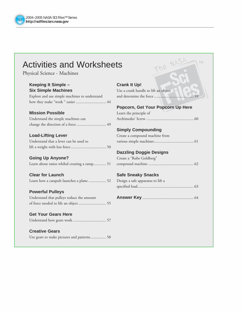
2004–2005 NASA SCI Files™ Serieshttp://scifiles.larc.nasa.gov4242
Activities and WorksheetsPhysical Science - Machines
Keeping It Simple – Six Simple MachinesExplore and use simple machines to understand
how they make “work “ easier ............................... 44
Mission PossibleUnderstand the simple machines can
change the direction of a force .............................. 49
Load-Lifting LeverUnderstand that a lever can be used to
lift a weight with less force .................................... 50
Going Up Anyone?Learn about ratios whiled creating a ramp............. 51
Clear for LaunchLearn how a catapult launches a plane .................. 52
Powerful PulleysUnderstand that pulleys reduce the amount
of force needed to life an object ............................ 55
Get Your Gears HereUnderstand how gears work .................................. 57
Creative GearsUse gears to make pictures and patterns ................ 58
Crank It Up!Use a crank handle to lift an object
and determine the force ........................................ 59
Popcorn, Get Your Popcorn Up HereLearn the principle of
Archimedes’ Screw ................................................ 60
Simply CompoundingCreate a compound machine from
various simple machines ........................................ 61
Dazzling Doggie DesignsCreate a “Rube Goldberg”
compound machine .............................................. 62
Safe Sneaky SnacksDesign a safe apparatus to lift a
specified load......................................................... 63
Answer Key .................................................... 64
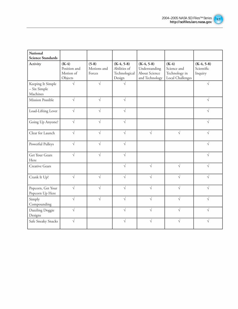
2004–2005 NASA SCI Files™ Serieshttp://scifiles.larc.nasa.gov
43
National Science Standards
Activity (K-4)Position and
Motion of
Objects
(5-8)Motions and
Forces
(K-4, 5-8)Abilities of
Technological
Design
(K-4, 5-8) Understanding
About Science
and Technology
(K-4) Science and
Technology in
Local Challenges
(K-4, 5-8)Scientifi c
Inquiry
Keeping It Simple
– Six Simple
Machines
√ √ √ √
Mission Possible √ √ √ √
Load-Lifting Lever √ √ √ √
Going Up Anyone? √ √ √ √
Clear for Launch √ √ √ √ √ √
Powerful Pulleys √ √ √ √
Get Your Gears
Here
√ √ √ √
Creative Gears √ √ √ √
Crank It Up! √ √ √ √ √ √
Popcorn, Get Your
Popcorn Up Here
√ √ √ √ √ √
Simply
Compounding
√ √ √ √ √ √
Dazzling Doggie
Designs
√ √ √ √ √
Safe Sneaky Snacks √ √ √ √ √
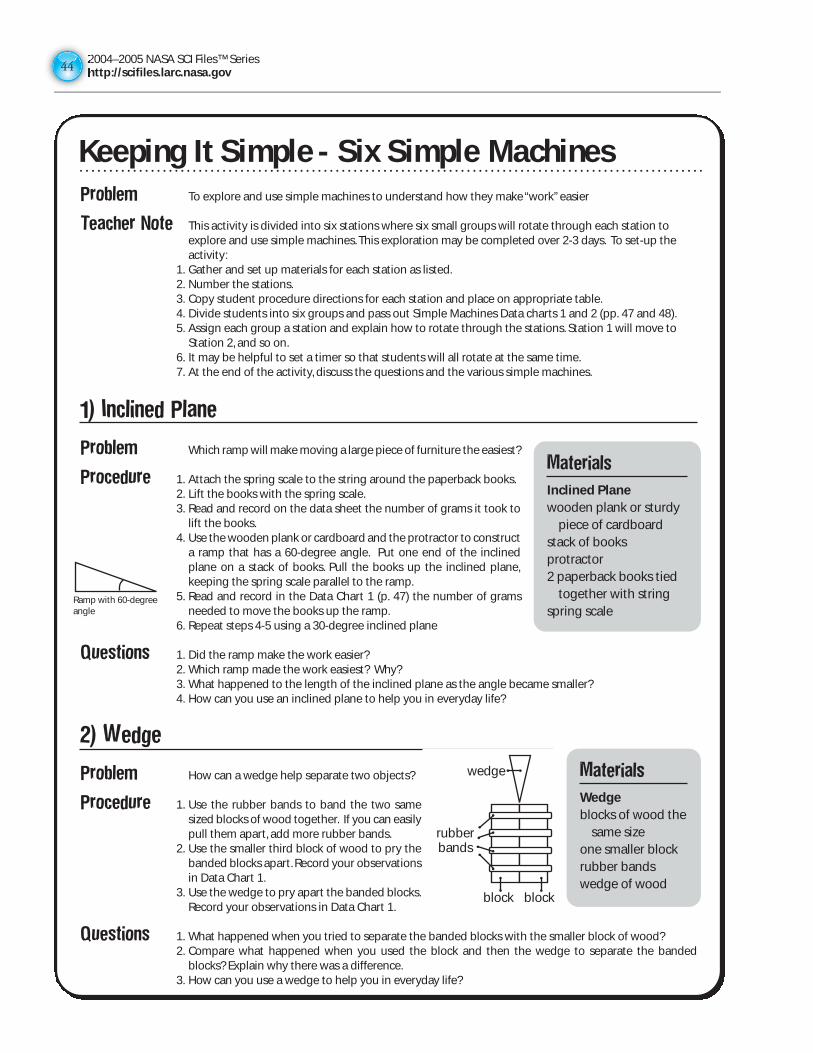
2004–2005 NASA SCI Files™ Serieshttp://scifiles.larc.nasa.gov4444
Problem To explore and use simple machines to understand how they make “work” easier
Teacher Note This activity is divided into six stations where six small groups will rotate through each station toexplore and use simple machines. This exploration may be completed over 2-3 days. To set-up theactivity:
1. Gather and set up materials for each station as listed.2. Number the stations.3. Copy student procedure directions for each station and place on appropriate table.4. Divide students into six groups and pass out Simple Machines Data charts 1 and 2 (pp. 47 and 48).5. Assign each group a station and explain how to rotate through the stations. Station 1 will move to
Station 2, and so on.6. It may be helpful to set a timer so that students will all rotate at the same time.7. At the end of the activity, discuss the questions and the various simple machines.
1) Inclined Plane
Problem Which ramp will make moving a large piece of furniture the easiest?
Procedure 1. Attach the spring scale to the string around the paperback books.2. Lift the books with the spring scale.3. Read and record on the data sheet the number of grams it took to
lift the books.4. Use the wooden plank or cardboard and the protractor to construct
a ramp that has a 60-degree angle. Put one end of the inclinedplane on a stack of books. Pull the books up the inclined plane,keeping the spring scale parallel to the ramp.
5. Read and record in the Data Chart 1 (p. 47) the number of gramsneeded to move the books up the ramp.
6. Repeat steps 4-5 using a 30-degree inclined plane
Questions 1. Did the ramp make the work easier?2. Which ramp made the work easiest? Why?3. What happened to the length of the inclined plane as the angle became smaller?4. How can you use an inclined plane to help you in everyday life?
2) Wedge
Problem How can a wedge help separate two objects?
Procedure 1. Use the rubber bands to band the two samesized blocks of wood together. If you can easilypull them apart, add more rubber bands.
2. Use the smaller third block of wood to pry thebanded blocks apart. Record your observationsin Data Chart 1.
3. Use the wedge to pry apart the banded blocks.Record your observations in Data Chart 1.
Questions 1. What happened when you tried to separate the banded blocks with the smaller block of wood?2. Compare what happened when you used the block and then the wedge to separate the banded
blocks? Explain why there was a difference.3. How can you use a wedge to help you in everyday life?
Keeping It Simple-Six Simple Machines
Materials
Inclined Planewooden plank or sturdy
piece of cardboardstack of booksprotractor2 paperback books tied
together with stringspring scale
Materials
Wedgeblocks of wood the
same size one smaller blockrubber bandswedge of wood
rubberbands
wedge
block block
Ramp with 60-degreeangle
Keeping It Simple - Six Simple Machines
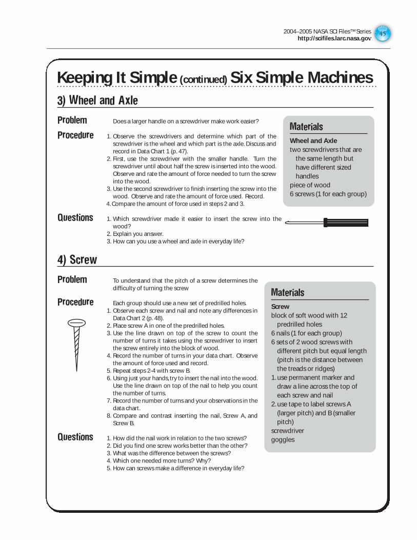
2004–2005 NASA SCI Files™ Serieshttp://scifiles.larc.nasa.gov
45
Keeping It Simple (continued) Six Simple Machines
3) Wheel and Axle
Problem Does a larger handle on a screwdriver make work easier?
Procedure 1. Observe the screwdrivers and determine which part of thescrewdriver is the wheel and which part is the axle. Discuss andrecord in Data Chart 1 (p. 47).
2. First, use the screwdriver with the smaller handle. Turn thescrewdriver until about half the screw is inserted into the wood.Observe and rate the amount of force needed to turn the screwinto the wood.
3. Use the second screwdriver to finish inserting the screw into thewood. Observe and rate the amount of force used. Record.
4. Compare the amount of force used in steps 2 and 3.
Questions 1. Which screwdriver made it easier to insert the screw into thewood?
2. Explain you answer.3. How can you use a wheel and axle in everyday life?
4) Screw
Problem To understand that the pitch of a screw determines thedifficulty of turning the screw
Procedure Each group should use a new set of predrilled holes.1. Observe each screw and nail and note any differences in
Data Chart 2 (p. 48).2. Place screw A in one of the predrilled holes.3. Use the line drawn on top of the screw to count the
number of turns it takes using the screwdriver to insertthe screw entirely into the block of wood.
4. Record the number of turns in your data chart. Observethe amount of force used and record.
5. Repeat steps 2-4 with screw B.6. Using just your hands, try to insert the nail into the wood.
Use the line drawn on top of the nail to help you countthe number of turns.
7. Record the number of turns and your observations in thedata chart.
8. Compare and contrast inserting the nail, Screw A, andScrew B.
Questions 1. How did the nail work in relation to the two screws?2. Did you find one screw works better than the other? 3. What was the difference between the screws?4. Which one needed more turns? Why?5. How can screws make a difference in everyday life?
Materials
Screwblock of soft wood with 12
predrilled holes6 nails (1 for each group)6 sets of 2 wood screws with
different pitch but equal length(pitch is the distance betweenthe treads or ridges)
1. use permanent marker anddraw a line across the top ofeach screw and nail
2. use tape to label screws A(larger pitch) and B (smallerpitch)
screwdriver goggles
Materials
Wheel and Axletwo screwdrivers that are
the same length buthave different sizedhandles
piece of wood 6 screws (1 for each group)
Keeping It Simple (continued) Six Simple Machines
2004–2005 NASA SCI Files™ Serieshttp://scifiles.larc.nasa.gov4646
Keeping It Simple (concluded) Six Simple Machines
5) Lever
Problem How does moving the fulcrum affect the amount of force needed in alever system?
Procedure 1. Place the dictionary 26 cm from the edge of the table.2. Place one end of the ruler under the dictionary so that the 1-cm mark is
covered.3. Place the fulcrum under the ruler at the 24 cm mark.4. Attach the spring scale to the ruler so that it is hanging downward.
Gently pull on the spring scale until you just begin to lift the dictionary.See diagram 1.
5. Read and record in Data Chart 2 (p. 48) the number of grams used.6. Keeping the 1-cm side of the ruler underneath the dictionary, move the
fulcrum to the 15-cm mark. Repeat steps 4-5.7. Repeat step 6, using 6 cm as the fulcrum’s position.
Questions 1. Did the number of grams used to lift the dictionarychange when you moved the fulcrum? How?
2. If you wanted to lift a heavy load, where should youplace the fulcrum?
3. How can you use levers to help you in everyday life?
6) Pulley
Problem How do pulleys make work easier?
Procedure 1. Use the spring scale to lift the weight off the floor or desk. Read andrecord the number of grams.
2. Attach the pulley to the ring stand.3. Attach one end of the string to the weight.4. Loop the other end through the pulley and attach the spring scale to
the end of the string. See diagram 1.5. Pull down on the spring scale to measure how many grams are needed
to lift the weight and record in Data Chart 2 (p. 48).6. Using a second pulley, construct the pulley system below. See
diagram 2.7. Pull up on the spring scale to lift the weight.
Read and record grams in the data chart.
Questions 1. Was there a difference between not using apulley and using one pulley?
2. What was the difference between using onepulley and using two pulleys?
3. Why would anyone want to use just one pulley?4. How can pulleys help you in everyday life?
Materials
Lever30-cm rulerdictionarysmall object such as
a pencil or base10 block forfulcrum
spring scale
Materials
Pulleytwo single pulleysring stand500 g weight80 cm of stringspring scale
dictionary ruler
Diagram 1spring scale
fulcrum
Diagram 1
500 g
hook
pulley
weight
SpringScale
Diagram 2
500 g
hook
pulley
pulley
weight
SpringScale
springscale
springscale
Keeping It Simple (concluded) Six Simple Machines
2004–2005 NASA SCI Files™ Serieshttp://scifiles.larc.nasa.gov
47
Keeping It Simple Data Chart 1
Inclined Plane
Questions:
1.
2.
3.
Wedge
Questions:
1.
2.
3.
Wheel and Axle
On a screwdriver, the wheel is the _________ and the axle is the _________.
Questions:
1.
2.
3.
Inclination in degrees Grams
0 º
30 º
60 º
Object Rate Observed Force
Small block
Wedge
Screwdriver Rate the Observed Force
Small-handled screwdriver
Large-handled screwdriver
Keeping It Simple Data Chart 1
2004–2005 NASA SCI Files™ Serieshttp://scifiles.larc.nasa.gov4848
Keeping It Simple Data Chart 2
Screw
Observations (compare and contrast nail, screw A, and Screw B).
Compare and contrast the insertion of screws A and B and the nail.
Questions:
1.
2.
3.
4.
5.
Lever
Questions:
1.
2.
3.
Pulley
Questions:
1.
2.
3.
4.
Position of Fulcrum Grams
24 cm
15 cm
6 cm
Number of Pulleys Grams
0
1
2
Screw Number of Turns Rate Observed Force
Nail
Screw A
Screw B
Keeping it Simple Data Chart 2
2004–2005 NASA SCI Files™ Serieshttp://scifiles.larc.nasa.gov
49
Mission PossibleProblem To understand that simple machines can change the direction
of a force
Scenario You are part of a rescue team that needs to get medicalsupplies to the other side of a flooded river. You don’t have aboat and only a limited number of supplies that include asmall piece of rope that is not long enough to reach the otherside.You also have access to a large plank of wood washed upby the flood and a log. Your mission is to devise a plan to getthe medical supplies to the people on the other side of theriver.
Procedure 1. Sort through your supplies: goggles, ruler (large plank), pencil(log), string (rope), mini marshmallows (bundles of medical supplies), tape, foam cup, andscissors.
2. Brainstorm how you are going to get the medical supplies to the other side.3. Construct your solution using only the supplies provided.4. If you are able to move your supplies 20 cm or more, then you have successfully completed
your mission. If your bundles fall short of 20 cm, then the supplies have washed downstream.The group who gets the most bundles across the river “wins” the competition.
5. Present your solution to the class and discuss how and why you used this solution.
Conclusion 1. In your solution, did applying a force in one direction cause a force in another direction?2. What other simple machines can change the direction of a force?3. Write a paragraph explaining your activity and how you used the items to move the medical
supplies. Explain the forces used and their change of direction.
Materials
30-cm rulerpencil or markerfoam cupstringscissorstape10 mini marshmallowsgoggles
Mission Possible
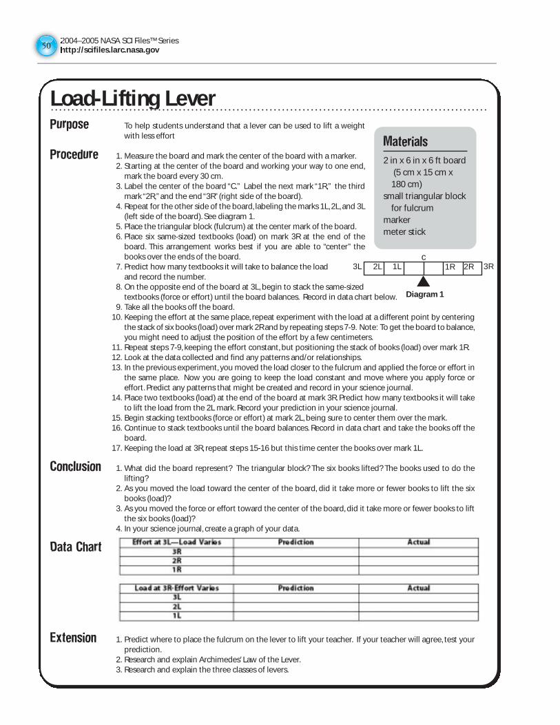
2004–2005 NASA SCI Files™ Serieshttp://scifiles.larc.nasa.gov5050
Load-Lifting LeverPurpose To help students understand that a lever can be used to lift a weight
with less effort
Procedure 1. Measure the board and mark the center of the board with a marker.2. Starting at the center of the board and working your way to one end,
mark the board every 30 cm.3. Label the center of the board “C.” Label the next mark “1R,” the third
mark “2R,” and the end “3R” (right side of the board).4. Repeat for the other side of the board, labeling the marks 1L, 2L, and 3L
(left side of the board). See diagram 1.5. Place the triangular block (fulcrum) at the center mark of the board.6. Place six same-sized textbooks (load) on mark 3R at the end of the
board. This arrangement works best if you are able to “center” thebooks over the ends of the board.
7. Predict how many textbooks it will take to balance the load and record the number.
8. On the opposite end of the board at 3L, begin to stack the same-sized textbooks (force or effort) until the board balances. Record in data chart below.
9. Take all the books off the board.10. Keeping the effort at the same place, repeat experiment with the load at a different point by centering
the stack of six books (load) over mark 2R and by repeating steps 7-9. Note: To get the board to balance,you might need to adjust the position of the effort by a few centimeters.
11. Repeat steps 7-9, keeping the effort constant, but positioning the stack of books (load) over mark 1R.12. Look at the data collected and find any patterns and/or relationships.13. In the previous experiment, you moved the load closer to the fulcrum and applied the force or effort in
the same place. Now you are going to keep the load constant and move where you apply force oreffort. Predict any patterns that might be created and record in your science journal.
14. Place two textbooks (load) at the end of the board at mark 3R. Predict how many textbooks it will taketo lift the load from the 2L mark. Record your prediction in your science journal.
15. Begin stacking textbooks (force or effort) at mark 2L, being sure to center them over the mark.16. Continue to stack textbooks until the board balances. Record in data chart and take the books off the
board.17. Keeping the load at 3R, repeat steps 15-16 but this time center the books over mark 1L.
Conclusion 1. What did the board represent? The triangular block? The six books lifted? The books used to do thelifting?
2. As you moved the load toward the center of the board, did it take more or fewer books to lift the sixbooks (load)?
3. As you moved the force or effort toward the center of the board, did it take more or fewer books to liftthe six books (load)?
4. In your science journal, create a graph of your data.
Data Chart
Extension 1. Predict where to place the fulcrum on the lever to lift your teacher. If your teacher will agree, test yourprediction.
2. Research and explain Archimedes’ Law of the Lever.3. Research and explain the three classes of levers.
Materials
2 in x 6 in x 6 ft board(5 cm x 15 cm x
180 cm)small triangular block
for fulcrummarkermeter stick
Diagram 1
c1R1L 2R 3R2L3L
Load-Lifting Lever
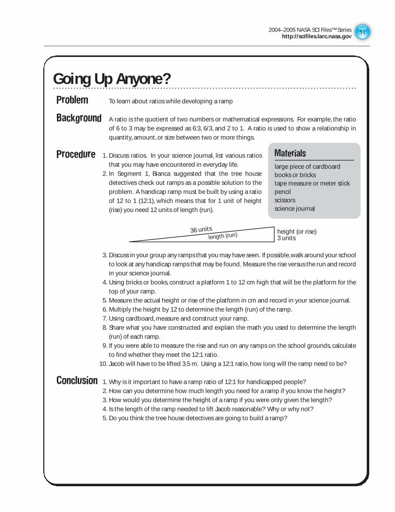
2004–2005 NASA SCI Files™ Serieshttp://scifiles.larc.nasa.gov
51
Going Up Anyone?
Problem To learn about ratios while developing a ramp
Background A ratio is the quotient of two numbers or mathematical expressions. For example, the ratio
of 6 to 3 may be expressed as 6:3, 6/3, and 2 to 1. A ratio is used to show a relationship in
quantity, amount, or size between two or more things.
Procedure 1. Discuss ratios. In your science journal, list various ratios
that you may have encountered in everyday life.
2. In Segment 1, Bianca suggested that the tree house
detectives check out ramps as a possible solution to the
problem. A handicap ramp must be built by using a ratio
of 12 to 1 (12:1), which means that for 1 unit of height
(rise) you need 12 units of length (run).
3. Discuss in your group any ramps that you may have seen. If possible, walk around your school
to look at any handicap ramps that may be found. Measure the rise versus the run and record
in your science journal.
4. Using bricks or books, construct a platform 1 to 12 cm high that will be the platform for the
top of your ramp.
5. Measure the actual height or rise of the platform in cm and record in your science journal.
6. Multiply the height by 12 to determine the length (run) of the ramp.
7. Using cardboard, measure and construct your ramp.
8. Share what you have constructed and explain the math you used to determine the length
(run) of each ramp.
9. If you were able to measure the rise and run on any ramps on the school grounds, calculate
to find whether they meet the 12:1 ratio.
10. Jacob will have to be lifted 3.5 m. Using a 12:1 ratio, how long will the ramp need to be?
Conclusion 1. Why is it important to have a ramp ratio of 12:1 for handicapped people?
2. How can you determine how much length you need for a ramp if you know the height?
3. How would you determine the height of a ramp if you were only given the length?
4. Is the length of the ramp needed to lift Jacob reasonable? Why or why not?
5. Do you think the tree house detectives are going to build a ramp?
Materials
large piece of cardboard books or brickstape measure or meter stickpencilscissorsscience journal
height (or rise)3 units
36 unitslength (run)
Going Up Anyone?
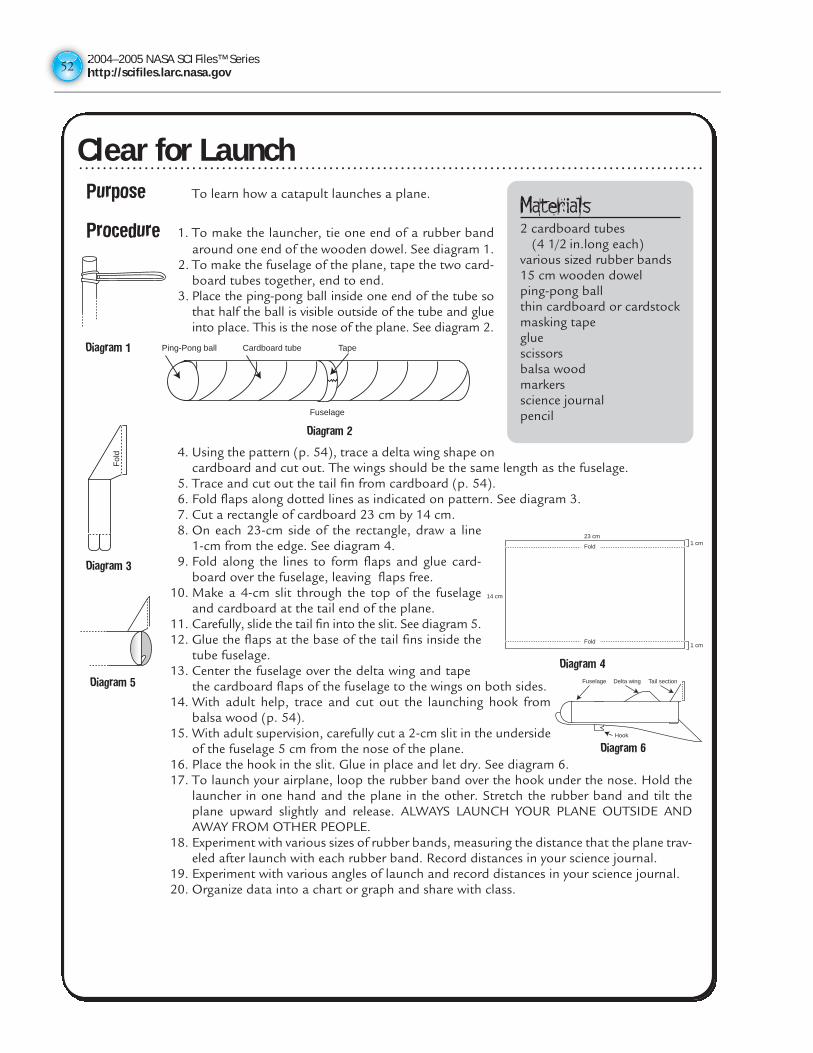
2004–2005 NASA SCI Files™ Serieshttp://scifiles.larc.nasa.gov5252
Clear for LaunchPurpose To learn how a catapult launches a plane.
Procedure 1. To make the launcher, tie one end of a rubber bandaround one end of the wooden dowel. See diagram 1.
2. To make the fuselage of the plane, tape the two card-board tubes together, end to end.
3. Place the ping-pong ball inside one end of the tube sothat half the ball is visible outside of the tube and glueinto place. This is the nose of the plane. See diagram 2.
4. Using the pattern (p. 54), trace a delta wing shape oncardboard and cut out. The wings should be the same length as the fuselage.
5. Trace and cut out the tail fin from cardboard (p. 54).6. Fold flaps along dotted lines as indicated on pattern. See diagram 3.7. Cut a rectangle of cardboard 23 cm by 14 cm. 8. On each 23-cm side of the rectangle, draw a line
1-cm from the edge. See diagram 4.9. Fold along the lines to form flaps and glue card-
board over the fuselage, leaving flaps free.10. Make a 4-cm slit through the top of the fuselage
and cardboard at the tail end of the plane.11. Carefully, slide the tail fin into the slit. See diagram 5.12. Glue the flaps at the base of the tail fins inside the
tube fuselage.13. Center the fuselage over the delta wing and tape
the cardboard flaps of the fuselage to the wings on both sides.14. With adult help, trace and cut out the launching hook from
balsa wood (p. 54).15. With adult supervision, carefully cut a 2-cm slit in the underside
of the fuselage 5 cm from the nose of the plane.16. Place the hook in the slit. Glue in place and let dry. See diagram 6.17. To launch your airplane, loop the rubber band over the hook under the nose. Hold the
launcher in one hand and the plane in the other. Stretch the rubber band and tilt theplane upward slightly and release. ALWAYS LAUNCH YOUR PLANE OUTSIDE ANDAWAY FROM OTHER PEOPLE.
18. Experiment with various sizes of rubber bands, measuring the distance that the plane trav-eled after launch with each rubber band. Record distances in your science journal.
19. Experiment with various angles of launch and record distances in your science journal.20. Organize data into a chart or graph and share with class.
Materials 2 cardboard tubes
(4 1/2 in.long each)various sized rubber bands15 cm wooden dowelping-pong ballthin cardboard or cardstockmasking tapegluescissorsbalsa woodmarkersscience journalpencil
Diagram 1 Ping-Pong ball Cardboard tube
Fuselage
Tape
Diagram 2
Fol
d
Diagram 3
23 cm
14 cm
1 cm
1 cm
Fold
Fold
Diagram 4
Diagram 5 Fuselage Delta wing Tail section
Hook
Diagram 6
Clear for Launch
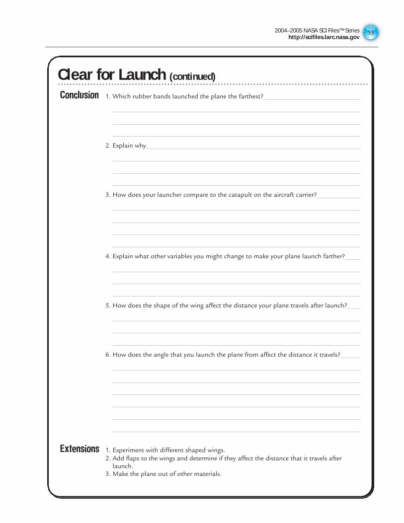
2004–2005 NASA SCI Files™ Serieshttp://scifiles.larc.nasa.gov
53
Clear for Launch (continued)Conclusion 1. Which rubber bands launched the plane the farthest?
2. Explain why.
3. How does your launcher compare to the catapult on the aircraft carrier?
4. Explain what other variables you might change to make your plane launch farther?
5. How does the shape of the wing affect the distance your plane travels after launch?
6. How does the angle that you launch the plane from affect the distance it travels?
Extensions 1. Experiment with different shaped wings.2. Add flaps to the wings and determine if they affect the distance that it travels after
launch.3. Make the plane out of other materials.
Clear for Launch (continued)
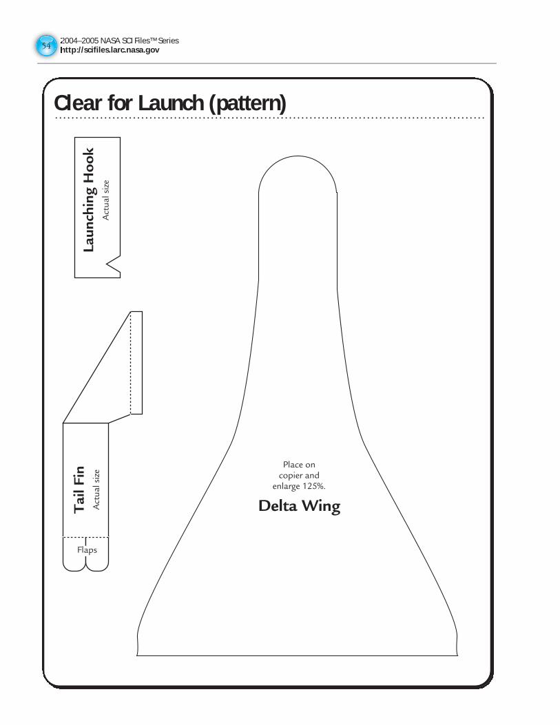
2004–2005 NASA SCI Files™ Serieshttp://scifiles.larc.nasa.gov5454
Clear for Launch (pattern)
Place on copier and
enlarge 125%.
Delta WingTai
l Fin
Act
ual s
ize
Laun
chin
g H
oo
kA
ctua
l siz
e
Flaps
Clear for Launch (pattern)
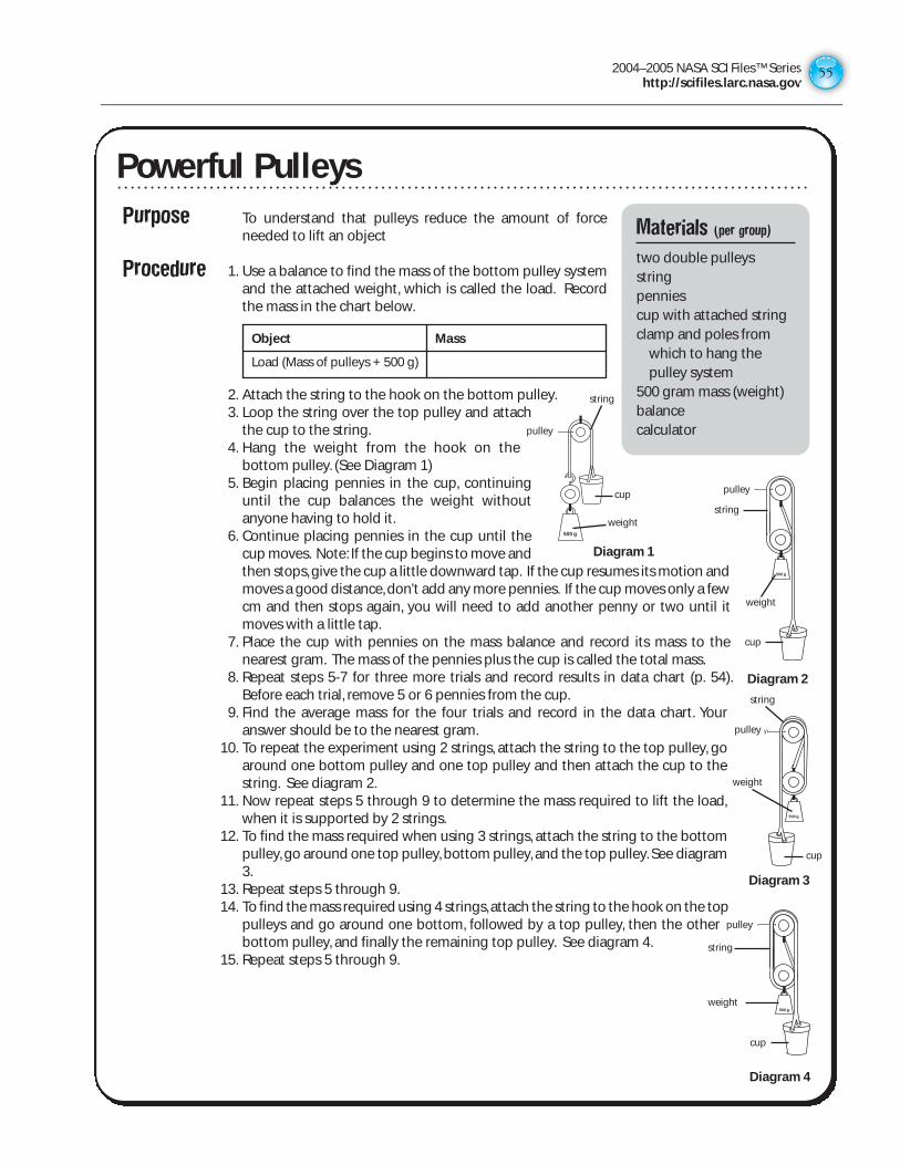
2004–2005 NASA SCI Files™ Serieshttp://scifiles.larc.nasa.gov
55
Powerful Pulleys
Purpose To understand that pulleys reduce the amount of forceneeded to lift an object
Procedure 1. Use a balance to find the mass of the bottom pulley systemand the attached weight, which is called the load. Recordthe mass in the chart below.
2. Attach the string to the hook on the bottom pulley.3. Loop the string over the top pulley and attach
the cup to the string.4. Hang the weight from the hook on the
bottom pulley. (See Diagram 1)5. Begin placing pennies in the cup, continuing
until the cup balances the weight withoutanyone having to hold it.
6. Continue placing pennies in the cup until thecup moves. Note: If the cup begins to move andthen stops, give the cup a little downward tap. If the cup resumes its motion andmoves a good distance, don’t add any more pennies. If the cup moves only a fewcm and then stops again, you will need to add another penny or two until itmoves with a little tap.
7. Place the cup with pennies on the mass balance and record its mass to thenearest gram. The mass of the pennies plus the cup is called the total mass.
8. Repeat steps 5-7 for three more trials and record results in data chart (p. 54).Before each trial, remove 5 or 6 pennies from the cup.
9. Find the average mass for the four trials and record in the data chart. Youranswer should be to the nearest gram.
10. To repeat the experiment using 2 strings, attach the string to the top pulley, goaround one bottom pulley and one top pulley and then attach the cup to thestring. See diagram 2.
11. Now repeat steps 5 through 9 to determine the mass required to lift the load,when it is supported by 2 strings.
12. To find the mass required when using 3 strings, attach the string to the bottompulley, go around one top pulley, bottom pulley, and the top pulley. See diagram3.
13. Repeat steps 5 through 9.14. To find the mass required using 4 strings, attach the string to the hook on the top
pulleys and go around one bottom, followed by a top pulley, then the otherbottom pulley, and finally the remaining top pulley. See diagram 4.
15. Repeat steps 5 through 9.
Materials (per group)
two double pulleys stringpenniescup with attached stringclamp and poles from
which to hang thepulley system
500 gram mass (weight)balancecalculator
Object Mass
Load (Mass of pulleys + 500 g)
500 g
pulley
pulley
500 g
500 g
pulley
Diagram 1
Diagram 2
Diagram 4
pulley
500 g
Diagram 3
string
cup
weightstring
cup
weight
string
cup
weight
string
cup
weight
pulley
pulley
pulley
pulley
Powerful Pulleys
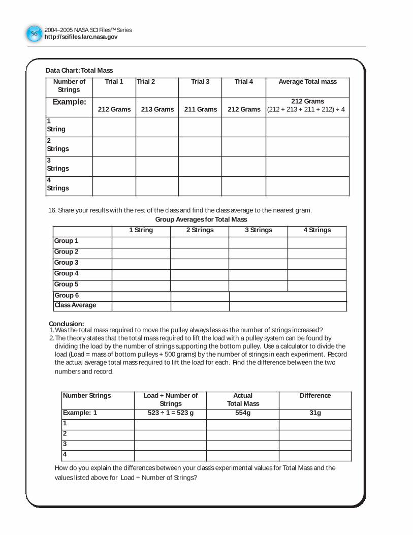
2004–2005 NASA SCI Files™ Serieshttp://scifiles.larc.nasa.gov5656
16. Share your results with the rest of the class and find the class average to the nearest gram.
Conclusion:1. Was the total mass required to move the pulley always less as the number of strings increased? 2. The theory states that the total mass required to lift the load with a pulley system can be found by
dividing the load by the number of strings supporting the bottom pulley. Use a calculator to divide the load (Load = mass of bottom pulleys + 500 grams) by the number of strings in each experiment. Recordthe actual average total mass required to lift the load for each. Find the difference between the two
numbers and record.
How do you explain the differences between your class’s experimental values for Total Mass and the
values listed above for Load ÷ Number of Strings?
Number of Strings
Trial 1 Trial 2 Trial 3 Trial 4 Average Total mass
Example:212 Grams 213 Grams 211 Grams 212 Grams
212 Grams(212 + 213 + 211 + 212) ÷ 4
1String
2Strings
3Strings
4Strings
1 String 2 Strings 3 Strings 4 Strings
Group 1
Group 2
Group 3
Group 4
Group 5
Data Chart: Total Mass
Group Averages for Total Mass
Group 6
Class Average
Number Strings Load ÷ Number ofStrings
ActualTotal Mass
Difference
Example: 1 523 ÷ 1 = 523 g 554g 31g
1
2
3
4
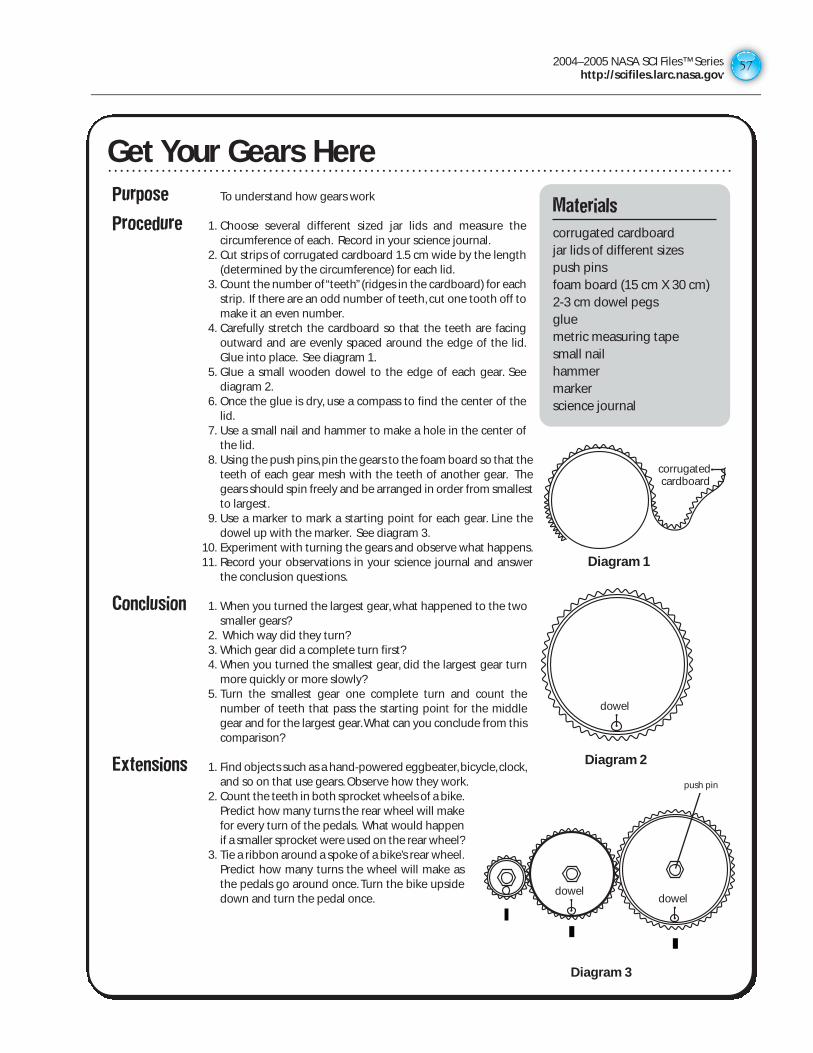
2004–2005 NASA SCI Files™ Serieshttp://scifiles.larc.nasa.gov
57
Get Your Gears HerePurpose To understand how gears work
Procedure 1. Choose several different sized jar lids and measure thecircumference of each. Record in your science journal.
2. Cut strips of corrugated cardboard 1.5 cm wide by the length(determined by the circumference) for each lid.
3. Count the number of “teeth”(ridges in the cardboard) for eachstrip. If there are an odd number of teeth, cut one tooth off tomake it an even number.
4. Carefully stretch the cardboard so that the teeth are facingoutward and are evenly spaced around the edge of the lid.Glue into place. See diagram 1.
5. Glue a small wooden dowel to the edge of each gear. Seediagram 2.
6. Once the glue is dry, use a compass to find the center of thelid.
7. Use a small nail and hammer to make a hole in the center ofthe lid.
8. Using the push pins, pin the gears to the foam board so that theteeth of each gear mesh with the teeth of another gear. Thegears should spin freely and be arranged in order from smallestto largest.
9. Use a marker to mark a starting point for each gear. Line thedowel up with the marker. See diagram 3.
10. Experiment with turning the gears and observe what happens.11. Record your observations in your science journal and answer
the conclusion questions.
Conclusion 1. When you turned the largest gear, what happened to the twosmaller gears?
2. Which way did they turn?3. Which gear did a complete turn first?4. When you turned the smallest gear, did the largest gear turn
more quickly or more slowly?5. Turn the smallest gear one complete turn and count the
number of teeth that pass the starting point for the middlegear and for the largest gear.What can you conclude from thiscomparison?
Extensions 1. Find objects such as a hand-powered eggbeater, bicycle, clock,and so on that use gears. Observe how they work.
2. Count the teeth in both sprocket wheels of a bike.Predict how many turns the rear wheel will makefor every turn of the pedals. What would happenif a smaller sprocket were used on the rear wheel?
3. Tie a ribbon around a spoke of a bike’s rear wheel.Predict how many turns the wheel will make asthe pedals go around once. Turn the bike upsidedown and turn the pedal once.
Materials
corrugated cardboardjar lids of different sizespush pinsfoam board (15 cm X 30 cm)2-3 cm dowel pegsgluemetric measuring tapesmall nailhammermarkerscience journal
Diagram 1
corrugated cardboard
Diagram 2
dowel
Diagram 3
doweldowel
Diagram 3
push pin
Get Your Gears Here
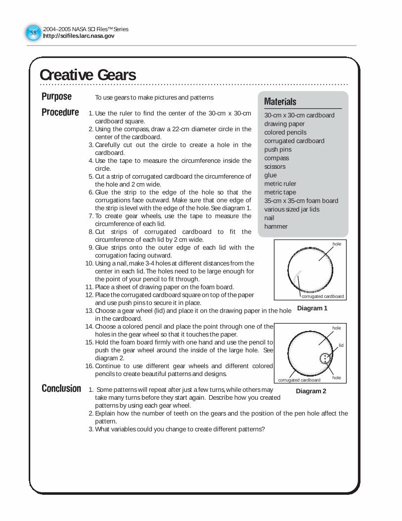
2004–2005 NASA SCI Files™ Serieshttp://scifiles.larc.nasa.gov5858
Purpose To use gears to make pictures and patterns
Procedure 1. Use the ruler to find the center of the 30-cm x 30-cmcardboard square.
2. Using the compass, draw a 22-cm diameter circle in thecenter of the cardboard.
3. Carefully cut out the circle to create a hole in thecardboard.
4. Use the tape to measure the circumference inside thecircle.
5. Cut a strip of corrugated cardboard the circumference ofthe hole and 2 cm wide.
6. Glue the strip to the edge of the hole so that thecorrugations face outward. Make sure that one edge ofthe strip is level with the edge of the hole. See diagram 1.
7. To create gear wheels, use the tape to measure thecircumference of each lid.
8. Cut strips of corrugated cardboard to fit thecircumference of each lid by 2 cm wide.
9. Glue strips onto the outer edge of each lid with thecorrugation facing outward.
10. Using a nail, make 3-4 holes at different distances from thecenter in each lid. The holes need to be large enough forthe point of your pencil to fit through.
11. Place a sheet of drawing paper on the foam board.12. Place the corrugated cardboard square on top of the paper
and use push pins to secure it in place.13. Choose a gear wheel (lid) and place it on the drawing paper in the hole
in the cardboard.14. Choose a colored pencil and place the point through one of the
holes in the gear wheel so that it touches the paper.15. Hold the foam board firmly with one hand and use the pencil to
push the gear wheel around the inside of the large hole. Seediagram 2.
16. Continue to use different gear wheels and different coloredpencils to create beautiful patterns and designs.
Conclusion 1. Some patterns will repeat after just a few turns, while others maytake many turns before they start again. Describe how you createdpatterns by using each gear wheel.
2. Explain how the number of teeth on the gears and the position of the pen hole affect thepattern.
3. What variables could you change to create different patterns?
Creative Gears
Materials
30-cm x 30-cm cardboarddrawing papercolored pencilscorrugated cardboardpush pinscompassscissorsgluemetric rulermetric tape35-cm x 35-cm foam boardvarious sized jar lidsnailhammer
Diagram 1
Diagram 2
hole
hole
hole
corrugated cardboard
corrugated cardboard
lid
Creative Gears
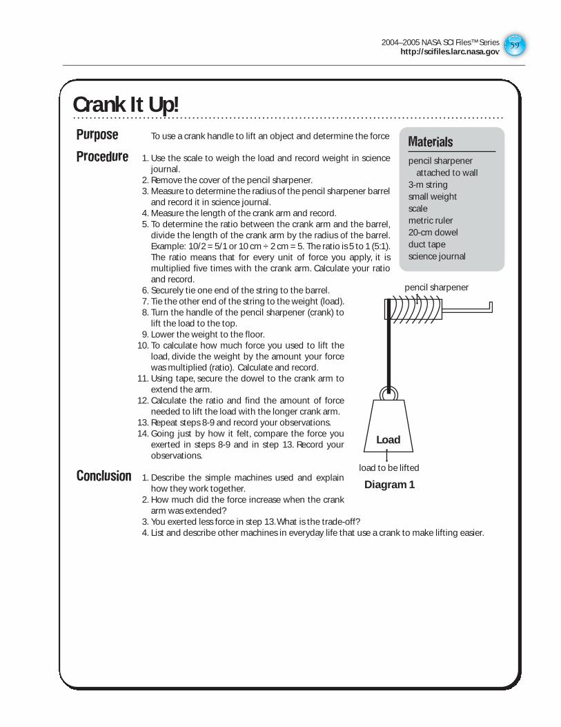
2004–2005 NASA SCI Files™ Serieshttp://scifiles.larc.nasa.gov
59
Crank It Up!Purpose To use a crank handle to lift an object and determine the force
Procedure 1. Use the scale to weigh the load and record weight in sciencejournal.
2. Remove the cover of the pencil sharpener.3. Measure to determine the radius of the pencil sharpener barrel
and record it in science journal.4. Measure the length of the crank arm and record.5. To determine the ratio between the crank arm and the barrel,
divide the length of the crank arm by the radius of the barrel.Example: 10/2 = 5/1 or 10 cm ÷ 2 cm = 5. The ratio is 5 to 1 (5:1).The ratio means that for every unit of force you apply, it ismultiplied five times with the crank arm. Calculate your ratioand record.
6. Securely tie one end of the string to the barrel.7. Tie the other end of the string to the weight (load).8. Turn the handle of the pencil sharpener (crank) to
lift the load to the top.9. Lower the weight to the floor.
10. To calculate how much force you used to lift theload, divide the weight by the amount your forcewas multiplied (ratio). Calculate and record.
11. Using tape, secure the dowel to the crank arm toextend the arm.
12. Calculate the ratio and find the amount of forceneeded to lift the load with the longer crank arm.
13. Repeat steps 8-9 and record your observations.14. Going just by how it felt, compare the force you
exerted in steps 8-9 and in step 13. Record yourobservations.
Conclusion 1. Describe the simple machines used and explainhow they work together.
2. How much did the force increase when the crankarm was extended?
3. You exerted less force in step 13. What is the trade-off?4. List and describe other machines in everyday life that use a crank to make lifting easier.
Materials
pencil sharpenerattached to wall
3-m string small weightscalemetric ruler20-cm dowel duct tapescience journal
Diagram 1
Load
load to be lifted
pencil sharpener
Crank It Up!
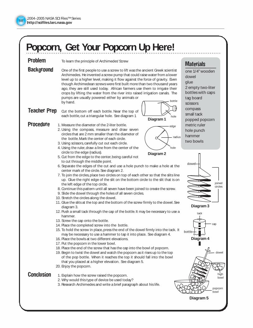
2004–2005 NASA SCI Files™ Serieshttp://scifiles.larc.nasa.gov6060
Problem To learn the principle of Archimedes’ Screw
Background One of the first people to use a screw to lift was the ancient Greek scientistArchimedes. He invented a screw pump that could raise water from a lowerlevel up to a higher level, making it flow against the force of gravity. Eventhough Archimedean screws were first built more than two thousand yearsago, they are still used today. African farmers use them to irrigate theircrops by lifting the water from the river into raised irrigation canals. Thepumps are usually powered either by animals orby hand.
Teacher Prep Cut the bottom off each bottle. Near the top ofeach bottle, cut a triangular hole. See diagram 1
Procedure 1. Measure the diameter of the 2-liter bottle.2. Using the compass, measure and draw seven
circles that are 2 mm smaller than the diameter ofthe bottle. Mark the center of each circle.
3. Using scissors, carefully cut out each circle.4. Using the ruler, draw a line from the center of the
circle to the edge (radius).5. Cut from the edge to the center, being careful not
to cut through the middle point.6. Separate the edges of the cut and use a hole punch to make a hole at the
center mark of the circle. See diagram 2.7. To join the circles, place two circles on top of each other so that the slits line
up. Glue the right edge of the slit on the bottom circle to the slit that is onthe left edge of the top circle.
8. Continue this pattern until all seven have been joined to create the screw.9. Slide the dowel through the holes of all seven circles.
10. Stretch the circles along the dowel.11. Glue the slits at the top and the bottom of the screw firmly to the dowel. See
diagram 3.12. Push a small tack through the cap of the bottle. It may be necessary to use a
hammer.13. Screw the cap onto the bottle.14. Place the completed screw into the bottle.15. To hold the screw in place, press the end of the dowel firmly into the tack. It
may be necessary to use a hammer to tap it into place. See diagram 4.16. Place the bowls at two different elevations.17. Put the popcorn in the lower bowl.18. Place the end of the screw that has the cap into the bowl of popcorn.19. Begin to twist the dowel and watch the popcorn as it rises up to the top
of the pop bottle. When it reaches the top it should fall into the bowlthat you placed at a higher elevation. See diagram 5.
20. Enjoy the popcorn.
Conclusion 1. Explain how the screw raised the popcorn.2. Why would this type of device be used today?3. Research Archimedes and write a brief paragraph about his life.
Materialsone 1/4” wooden dowelglue2 empty two-liter bottles with capstag boardscissorscompasssmall tackpopped popcornmetric rulerhole punchhammertwo bowls
Popcorn, Get Your Popcorn Up Here!
Diagram 3
Diagram 4
bottle
dowel
nail
Diagram 1
Diagram 2
Diagram 5Diagram 5
bottle
hole
edge
radius
hole
joinedcircles
tack
cap
dowel
highbowl
popcornbowl
Popcorn, Get Your Popcorn Up Here!
2004–2005 NASA SCI Files™ Serieshttp://scifiles.larc.nasa.gov
61
Purpose To create a compound machine from various simple machines
Teacher Note: Students will need to know how to copy and paste pictures from the Internet into a new document. It will also be helpful if they are able to use computer software to draw a final product and present their work.
Internet Sites Invention Dimension http://web.mit.edu/afs/athena.mit.edu/org/i/invent/ Inventor’s Toolbox http://www.mos.org/sln/Leonardo/InventorsToolbox.html Marvelous Machines http://www.galaxy.net/~k12/machines/index.shtml Rube Goldberg http://www.rube-goldberg.com/
Procedure 1. Working with a partner and using the suggested web sites, locate examples of simple
machines.
2. In your science journal, write a definition of the six different simple machines: lever, pulley,
screw, inclined plane, wheel and axle, and wedge.
3. Import a picture of each machine into a program such as Kid Pix® or The Writing Center®.
Label each picture with the name of the machine.
4. Visit the Rube Goldberg web site and look at the gallery of pictures created by Mr.
Goldberg. Discuss his use of simple machines to make a more complex machine for a
simple task.
5. Using a program such as Kid Pix®, create a drawing of a brand new contraption by using at
least two simple machines.
6. Name the machine and write a description of how it works and how it is used to help make
life more “simple.” Be sure to label all the parts.
Simply CompoundingMaterials
internetdrawing softwarescience journal
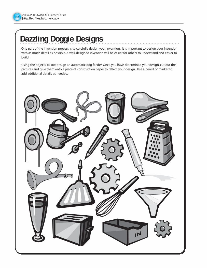
2004–2005 NASA SCI Files™ Serieshttp://scifiles.larc.nasa.gov6262
Dazzling Doggie DesignsOne part of the invention process is to carefully design your invention. It is important to design your inventionwith as much detail as possible. A well-designed invention will be easier for others to understand and easier tobuild.
Using the objects below, design an automatic dog feeder. Once you have determined your design, cut out thepictures and glue them onto a piece of construction paper to reflect your design. Use a pencil or marker toadd additional details as needed.
Dazzling Doggie Designs
2004–2005 NASA SCI Files™ Serieshttp://scifiles.larc.nasa.gov
63
Safe, Sneaky SnacksPurpose To design a safe apparatus to lift a specified load
Teacher Note Prior to performing the activity, you will need to construct a10-cm x 30-cm x 3-m rectangular vent from cardboard forstudents to use for testing their apparatuses. Allow studentsone-two days to research and design an apparatus. Providebasic materials or have students bring supplies from hometo complete their design. Rubrics and other evaluation toolsare provided on the NASA SCI Files™ web site that may beprinted and given to students for assessment.http://scifiles.larc.nasa.gov/educators/index.html
Procedure Shannon and Blair are trying to sneak snacks up to theirplayroom without their little sister’s knowledge. They havedecided to set up a pulley system inside a 10-cm x 30-cmair-conditioning vent. The playroom is located 3 metersdirectly above the kitchen. They have to make sure thattheir snacks don’t fall since the snacks are eggs! To helpShannon and Blair, you need to design an apparatus to liftthe snacks quietly and safely.
1. In your group, discuss the situation, determine “what you know” and create a list in your sciencejournal. To help in your design process, a copy of the Design Log can be obtained from the NASA SCIFiles™ web site <http://scifiles.larc.nasa.gov/educators/tools/pbl/design_log.html>
2. Reach a consensus about “what you need to know”and conduct research using books, the Internet, andother available resources.
3. Design your apparatus, creating detailed drawings, descriptions, and a materials list needed for yourdesign. Note: At your teacher’s discretion, materials may be brought from home to help construct yourapparatus.
4. Be sure that you have considered and addressed all the appropriate safety issues.5. To construct your apparatus, gather the materials needed and work as a team to create a safe apparatus
for your egg snacks.6. Once the apparatus is completed, conduct a test run with a plastic egg to make sure your apparatus is
safe for your real egg.7. If problems are encountered in your test run, redesign and make changes as needed. Conduct a second
test run. Repeat until test run is successful.8. Lift your egg in the apparatus.
Conclusion 1. What safety precautions did you take to ensure that the egg would survive the trip up the vent?2. What type of backup plan would you make if the apparatus fell down the vent past the kitchen and into
the basement?3. What materials worked the best in this project?4. What materials are the safest?5. How did your research help you design the apparatus?6. How can the tree house detectives make their lift chair safer?
Extension Test the students’ apparatuses in an “egg drop” contest to see which ones best protect the egg from afall.
Materialsscience journaleggsmetric rulersencyclopediasinternet accessstringcardboardshoe boxesscissorsscraps of materialcottonfoamgluetapethread spools or pulleysplastic eggs
Safe, Sneaky Snacks
2004–2005 NASA SCI Files™ Serieshttp://scifiles.larc.nasa.gov6464
ANSWER KEY
Keeping It Simple - Six Simple Machines
Inclined Plane
1. Yes.
2. The 30-dregree ramp used the least amount of force to lift the weight. When you increase the height of the ramp, you increase the amount of force necessary to move the weight. For example, if you have a 500-g weight at a 30- degree angle, it might take 125 g to move it up the ramp. However, when the ramp is set at 60 degrees, you have to overcome more height, which results in using more force.
3. The length of the ramp increased as the angle became smaller.
4. Answers will vary but might include that ramps can be used to move furniture, help make places accessible to people in wheelchairs, and help cars go up steep mountains.
Wedge
1. The banded blocks could not be separated with the smaller block of wood.
2. The wedge was able to get between the banded blocks and separate them unlike the block. The wedge is thinner on one end and that allows it to fit in small, tight places.
3. Answers will vary but might include splitting firewood, loosening boards on a fence, and prying hubcaps off a tire.
Wheel and Axle
1. The screwdriver with the larger handle.
2. The ratio between the handle (wheel) and the shaft (axle) is larger on the larger handled screwdriver. With a larger ratio, you divide the weight by a larger number and get a smaller amount of force needed.
3. Answer will vary but might include a Ferris wheel, wheelbarrow, and moving boxes on rollers.
Screw
1. Unlike the screws, the nail was unable to go into the wood.
2. Screw B went into the wood easier than screw A.
3. The difference between the two screws was the distance between the threads. Screw B’s threads had a smaller distance between them.
4. It took more turns to get screw B into the wood because you had to turn it over a longer distance since the pitch was smaller. Even though you had to turn Screw B more times, it made the force less. That is called a tradeoff.
5. Answers will vary, but might include securing items to a wall, connecting the stems of eye glasses to the frames, and putting machines together.
Lever
1. Yes. The farther away from the dictionary the fulcrum was moved, the more grams of force it took to lift it.
2. To lift a heavy load, place the fulcrum close to the load.
3. Answers will vary, but might include a seesaw,moving large rocks, and lifting a heavy item to slide something under it.
Pulley
1. No. The amount of grams (force) used was the same.
2. The amount of force needed to move the load decreased when using the two-pulley system.
3. You can use one pulley to change the direction of the force. It is easier to pull down than to lift up, so this makes work easier.
4. Answers will vary, but might include loading containers on and off boats, lifting heavy objects up to a second story building, and taking a motor out of a car.
Mission Possible
1. The solution to this problem is probably going to be the construction of a catapult, using the plank and the ruler to launch the supplies to the other side. As force is applied to one end of the plank, it creates a force on the other end of the plank,moving in the opposite direction. This device will then launch the supplies through the air and hopefully, to the other side.
2. Many other simple machines can change the direction of a force. For example, when using a single pulley, you pull down to move the load upward. When using a wedge, you push down to move the load laterally. When using a gear, you turn one gear to move another gear in the opposite direction.
Load-Lifting Lever
Data Chart
1. The board represented the lever, the block was the fulcrum, the six books were the load or resistance, the books used to do the lifting were the force or effort needed to lift the load.
2. As you moved the triangular block (fulcrum) toward the end of the board (load), it took fewer books (effort) to lift the six books.
3. It took more books to lift the load as you moved toward the fulcrum. If your force is 5 times further from the fulcrum than the load, then you multiply the force 5 times. The trade-off is that the distance you have to push down will be 5 times greater than the load distance (how far it moves up).
4. Graphs will vary.
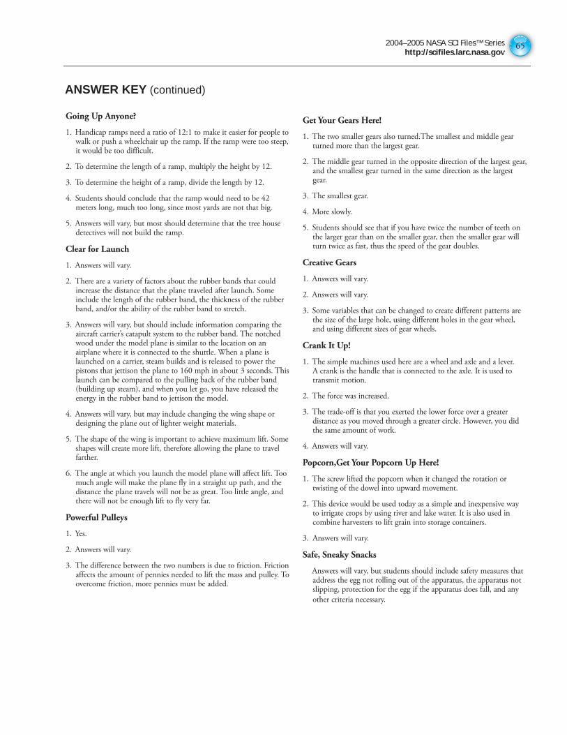
2004–2005 NASA SCI Files™ Serieshttp://scifiles.larc.nasa.gov
65
ANSWER KEY (continued)
Going Up Anyone?
1. Handicap ramps need a ratio of 12:1 to make it easier for people to walk or push a wheelchair up the ramp. If the ramp were too steep, it would be too difficult.
2. To determine the length of a ramp, multiply the height by 12.
3. To determine the height of a ramp, divide the length by 12.
4. Students should conclude that the ramp would need to be 42 meters long, much too long, since most yards are not that big.
5. Answers will vary, but most should determine that the tree house detectives will not build the ramp.
Clear for Launch
1. Answers will vary.
2. There are a variety of factors about the rubber bands that could increase the distance that the plane traveled after launch. Some include the length of the rubber band, the thickness of the rubber band, and/or the ability of the rubber band to stretch.
3. Answers will vary, but should include information comparing the aircraft carrier’s catapult system to the rubber band. The notched wood under the model plane is similar to the location on an airplane where it is connected to the shuttle. When a plane is launched on a carrier, steam builds and is released to power the pistons that jettison the plane to 160 mph in about 3 seconds. This launch can be compared to the pulling back of the rubber band (building up steam), and when you let go, you have released the energy in the rubber band to jettison the model.
4. Answers will vary, but may include changing the wing shape or designing the plane out of lighter weight materials.
5. The shape of the wing is important to achieve maximum lift. Some shapes will create more lift, therefore allowing the plane to travel farther.
6. The angle at which you launch the model plane will affect lift. Too much angle will make the plane fly in a straight up path, and the distance the plane travels will not be as great. Too little angle, and there will not be enough lift to fly very far.
Powerful Pulleys
1. Yes.
2. Answers will vary.
3. The difference between the two numbers is due to friction. Friction affects the amount of pennies needed to lift the mass and pulley. To overcome friction, more pennies must be added.
Get Your Gears Here!
1. The two smaller gears also turned.The smallest and middle gear turned more than the largest gear.
2. The middle gear turned in the opposite direction of the largest gear, and the smallest gear turned in the same direction as the largest gear.
3. The smallest gear.
4. More slowly.
5. Students should see that if you have twice the number of teeth on the larger gear than on the smaller gear, then the smaller gear will turn twice as fast, thus the speed of the gear doubles.
Creative Gears
1. Answers will vary.
2. Answers will vary.
3. Some variables that can be changed to create different patterns are the size of the large hole, using different holes in the gear wheel, and using different sizes of gear wheels.
Crank It Up!
1. The simple machines used here are a wheel and axle and a lever. A crank is the handle that is connected to the axle. It is used to transmit motion.
2. The force was increased.
3. The trade-off is that you exerted the lower force over a greater distance as you moved through a greater circle. However, you did the same amount of work.
4. Answers will vary.
Popcorn,Get Your Popcorn Up Here!
1. The screw lifted the popcorn when it changed the rotation or twisting of the dowel into upward movement.
2. This device would be used today as a simple and inexpensive way to irrigate crops by using river and lake water. It is also used in combine harvesters to lift grain into storage containers.
3. Answers will vary.
Safe, Sneaky Snacks
Answers will vary, but students should include safety measures that address the egg not rolling out of the apparatus, the apparatus not slipping, protection for the egg if the apparatus does fall, and any
other criteria necessary.

Physical ScienceENGINEERING DESIGN
SECTION III
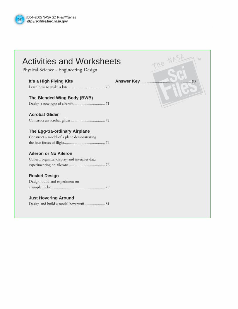
2004–2005 NASA SCI Files™ Serieshttp://scifiles.larc.nasa.gov6868
Activities and WorksheetsPhysical Science - Engineering Design
It’s a High Flying KiteLearn how to make a kite ...................................... 70
The Blended Wing Body (BWB)Design a new type of aircraft ................................. 71
Acrobat GliderConstruct an acrobat glider ................................... 72
The Egg-tra-ordinary AirplaneConstruct a model of a plane demonstrating
the four forces of flight .......................................... 74
Aileron or No AileronCollect, organize, display, and interpret data
experimenting on ailerons ..................................... 76
Rocket DesignDesign, build and experiment on
a simple rocket ...................................................... 79
Just Hovering AroundDesign and build a model hovercraft..................... 81
Answer Key .................................................... 83
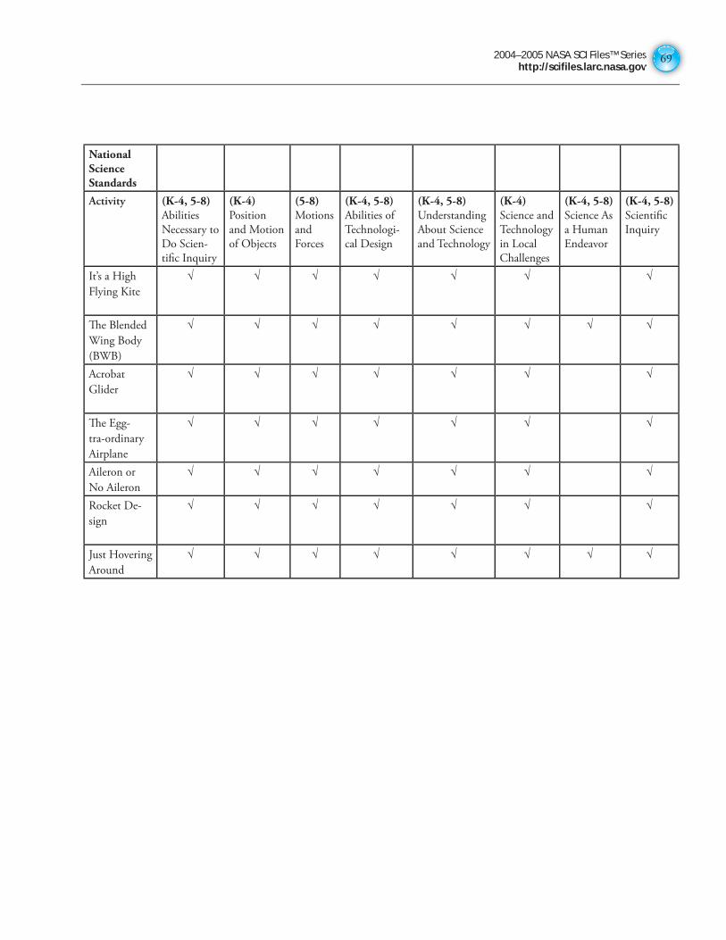
2004–2005 NASA SCI Files™ Serieshttp://scifiles.larc.nasa.gov
69
National Science Standards
Activity (K-4, 5-8)Abilities
Necessary to
Do Scien-
tifi c Inquiry
(K-4)Position
and Motion
of Objects
(5-8)Motions
and
Forces
(K-4, 5-8)Abilities of
Technologi-
cal Design
(K-4, 5-8) Understanding
About Science
and Technology
(K-4) Science and
Technology
in Local
Challenges
(K-4, 5-8)Science As
a Human
Endeavor
(K-4, 5-8)Scientifi c
Inquiry
It’s a High
Flying Kite
√ √ √ √ √ √ √
Th e Blended
Wing Body
(BWB)
√ √ √ √ √ √ √ √
Acrobat
Glider
√ √ √ √ √ √ √
Th e Egg-
tra-ordinary
Airplane
√ √ √ √ √ √ √
Aileron or
No Aileron
√ √ √ √ √ √ √
Rocket De-
sign
√ √ √ √ √ √ √
Just Hovering
Around
√ √ √ √ √ √ √ √
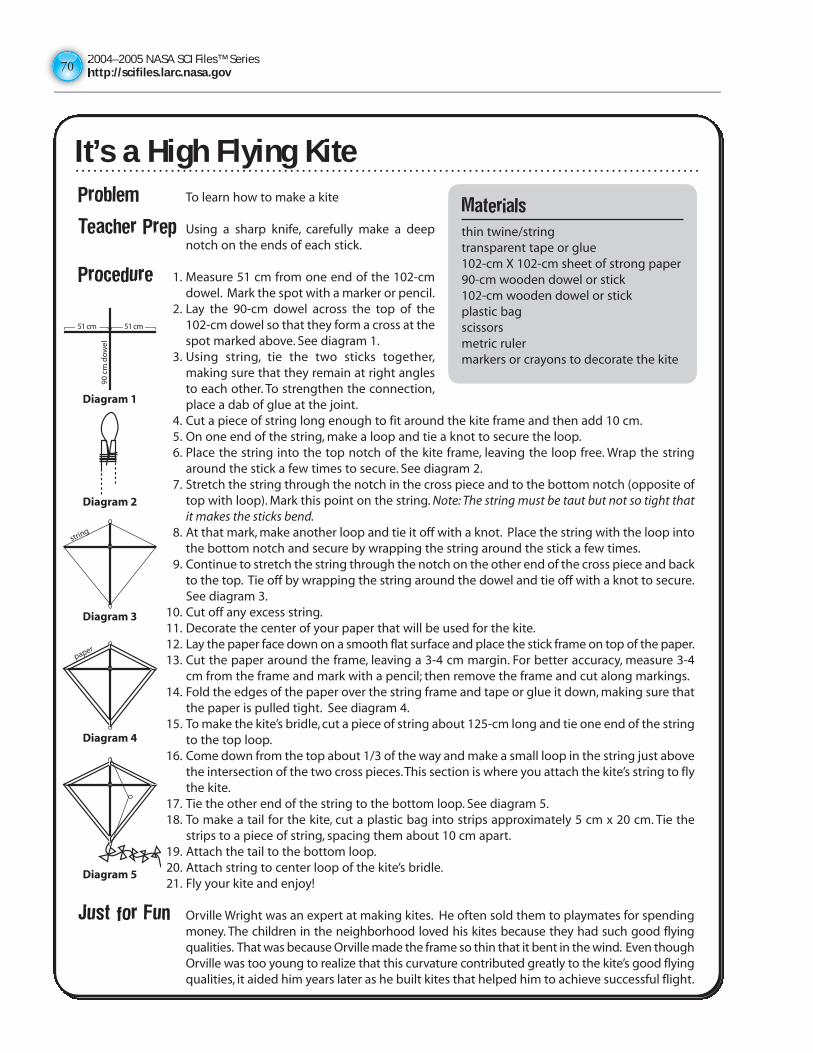
2004–2005 NASA SCI Files™ Serieshttp://scifiles.larc.nasa.gov7070
It’s a High Flying KiteProblem To learn how to make a kite
Teacher Prep Using a sharp knife, carefully make a deepnotch on the ends of each stick.
Procedure 1. Measure 51 cm from one end of the 102-cmdowel. Mark the spot with a marker or pencil.
2. Lay the 90-cm dowel across the top of the102-cm dowel so that they form a cross at thespot marked above. See diagram 1.
3. Using string, tie the two sticks together,making sure that they remain at right anglesto each other. To strengthen the connection,place a dab of glue at the joint.
4. Cut a piece of string long enough to fit around the kite frame and then add 10 cm.5. On one end of the string, make a loop and tie a knot to secure the loop.6. Place the string into the top notch of the kite frame, leaving the loop free. Wrap the string
around the stick a few times to secure. See diagram 2.7. Stretch the string through the notch in the cross piece and to the bottom notch (opposite of
top with loop). Mark this point on the string. Note: The string must be taut but not so tight thatit makes the sticks bend.
8. At that mark, make another loop and tie it off with a knot. Place the string with the loop intothe bottom notch and secure by wrapping the string around the stick a few times.
9. Continue to stretch the string through the notch on the other end of the cross piece and backto the top. Tie off by wrapping the string around the dowel and tie off with a knot to secure.See diagram 3.
10. Cut off any excess string.11. Decorate the center of your paper that will be used for the kite.12. Lay the paper face down on a smooth flat surface and place the stick frame on top of the paper.13. Cut the paper around the frame, leaving a 3-4 cm margin. For better accuracy, measure 3-4
cm from the frame and mark with a pencil; then remove the frame and cut along markings.14. Fold the edges of the paper over the string frame and tape or glue it down, making sure that
the paper is pulled tight. See diagram 4.15. To make the kite’s bridle, cut a piece of string about 125-cm long and tie one end of the string
to the top loop.16. Come down from the top about 1/3 of the way and make a small loop in the string just above
the intersection of the two cross pieces.This section is where you attach the kite’s string to flythe kite.
17. Tie the other end of the string to the bottom loop. See diagram 5.18. To make a tail for the kite, cut a plastic bag into strips approximately 5 cm x 20 cm. Tie the
strips to a piece of string, spacing them about 10 cm apart.19. Attach the tail to the bottom loop.20. Attach string to center loop of the kite’s bridle.21. Fly your kite and enjoy!
Just for Fun Orville Wright was an expert at making kites. He often sold them to playmates for spendingmoney. The children in the neighborhood loved his kites because they had such good flyingqualities. That was because Orville made the frame so thin that it bent in the wind. Even thoughOrville was too young to realize that this curvature contributed greatly to the kite’s good flyingqualities, it aided him years later as he built kites that helped him to achieve successful flight.
Materials
thin twine/stringtransparent tape or glue102-cm X 102-cm sheet of strong paper90-cm wooden dowel or stick102-cm wooden dowel or stickplastic bagscissorsmetric rulermarkers or crayons to decorate the kite
51 cm
90 c
m d
ow
el
51 cm
Diagram 1
Diagram 2
Diagram 3
Diagram 4
string
paper
Diagram 5
It’s a High Flying Kite
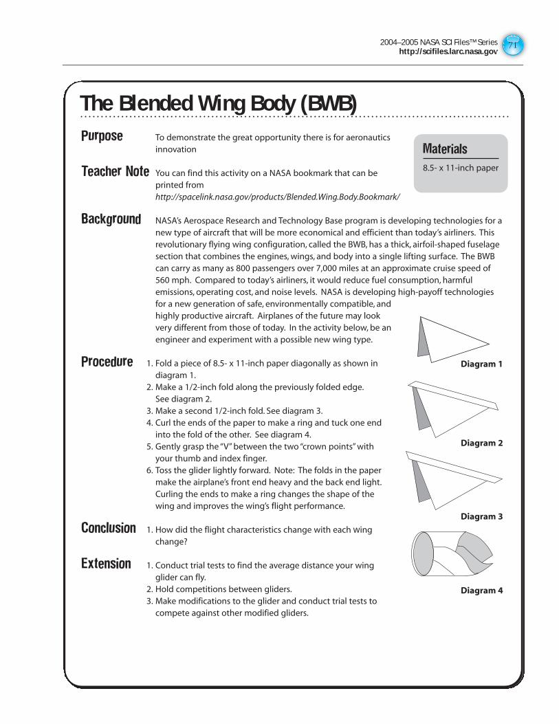
2004–2005 NASA SCI Files™ Serieshttp://scifiles.larc.nasa.gov
71
Purpose To demonstrate the great opportunity there is for aeronauticsinnovation
Teacher Note You can find this activity on a NASA bookmark that can beprinted fromhttp://spacelink.nasa.gov/products/Blended.Wing.Body.Bookmark/
Background NASA’s Aerospace Research and Technology Base program is developing technologies for anew type of aircraft that will be more economical and efficient than today’s airliners. Thisrevolutionary flying wing configuration, called the BWB, has a thick, airfoil-shaped fuselagesection that combines the engines, wings, and body into a single lifting surface. The BWBcan carry as many as 800 passengers over 7,000 miles at an approximate cruise speed of560 mph. Compared to today’s airliners, it would reduce fuel consumption, harmfulemissions, operating cost, and noise levels. NASA is developing high-payoff technologiesfor a new generation of safe, environmentally compatible, andhighly productive aircraft. Airplanes of the future may lookvery different from those of today. In the activity below, be anengineer and experiment with a possible new wing type.
Procedure 1. Fold a piece of 8.5- x 11-inch paper diagonally as shown indiagram 1.
2. Make a 1/2-inch fold along the previously folded edge.See diagram 2.
3. Make a second 1/2-inch fold. See diagram 3.4. Curl the ends of the paper to make a ring and tuck one end
into the fold of the other. See diagram 4.5. Gently grasp the “V” between the two “crown points” with
your thumb and index finger.6. Toss the glider lightly forward. Note: The folds in the paper
make the airplane’s front end heavy and the back end light.Curling the ends to make a ring changes the shape of thewing and improves the wing’s flight performance.
Conclusion 1. How did the flight characteristics change with each wingchange?
Extension 1. Conduct trial tests to find the average distance your wingglider can fly.
2. Hold competitions between gliders.3. Make modifications to the glider and conduct trial tests to
compete against other modified gliders.
The Blended Wing Body (BWB)
Materials
8.5- x 11-inch paper
Diagram 1
Diagram 2
Diagram 3
Diagram 4
The Blended Wing Body (BWB)
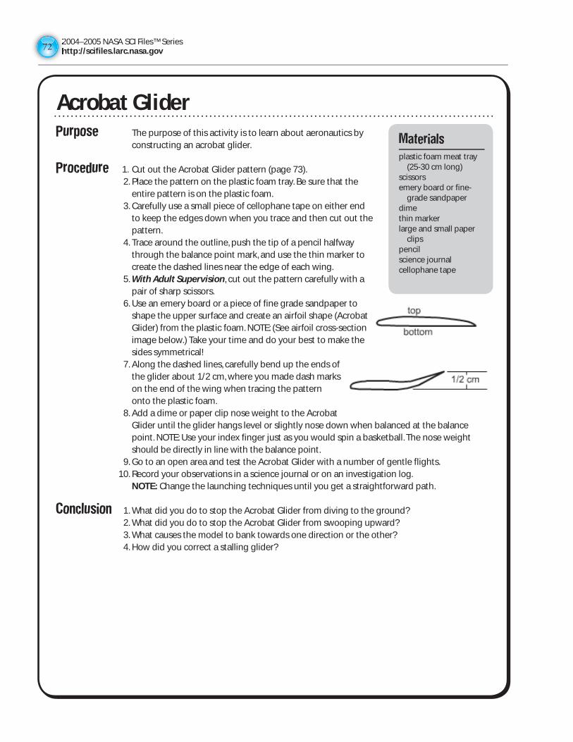
2004–2005 NASA SCI Files™ Serieshttp://scifiles.larc.nasa.gov7272
Purpose The purpose of this activity is to learn about aeronautics by constructing an acrobat glider.
Procedure 1. Cut out the Acrobat Glider pattern (page 73). 2. Place the pattern on the plastic foam tray. Be sure that the
entire pattern is on the plastic foam. 3. Carefully use a small piece of cellophane tape on either end
to keep the edges down when you trace and then cut out the pattern.
4. Trace around the outline, push the tip of a pencil halfway through the balance point mark, and use the thin marker to create the dashed lines near the edge of each wing.
5. With Adult Supervision, cut out the pattern carefully with a pair of sharp scissors.
6. Use an emery board or a piece of fine grade sandpaper to shape the upper surface and create an airfoil shape (Acrobat Glider) from the plastic foam. NOTE: (See airfoil cross-section image below.) Take your time and do your best to make the sides symmetrical!
7. Along the dashed lines, carefully bend up the ends of the glider about 1/2 cm, where you made dash marks on the end of the wing when tracing the pattern onto the plastic foam.
8. Add a dime or paper clip nose weight to the Acrobat Glider until the glider hangs level or slightly nose down when balanced at the balance point. NOTE: Use your index finger just as you would spin a basketball. The nose weight should be directly in line with the balance point.
9. Go to an open area and test the Acrobat Glider with a number of gentle flights. 10. Record your observations in a science journal or on an investigation log.
NOTE: Change the launching techniques until you get a straightforward path.
Conclusion 1. What did you do to stop the Acrobat Glider from diving to the ground? 2. What did you do to stop the Acrobat Glider from swooping upward? 3. What causes the model to bank towards one direction or the other? 4. How did you correct a stalling glider?
Acrobat GliderMaterials
plastic foam meat tray (25-30 cm long)
scissorsemery board or fine-
grade sandpaperdimethin markerlarge and small paper
clipspencilscience journalcellophane tape
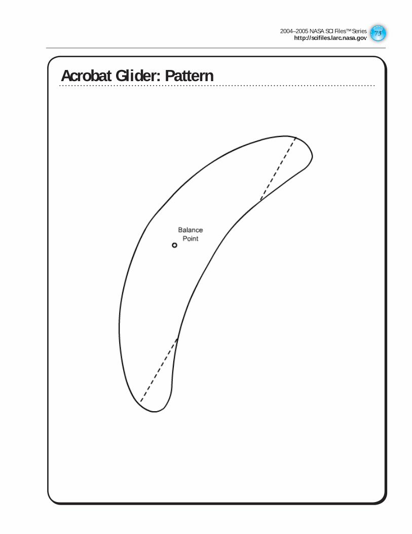
2004–2005 NASA SCI Files™ Serieshttp://scifiles.larc.nasa.gov
73
Acrobat Glider: Pattern
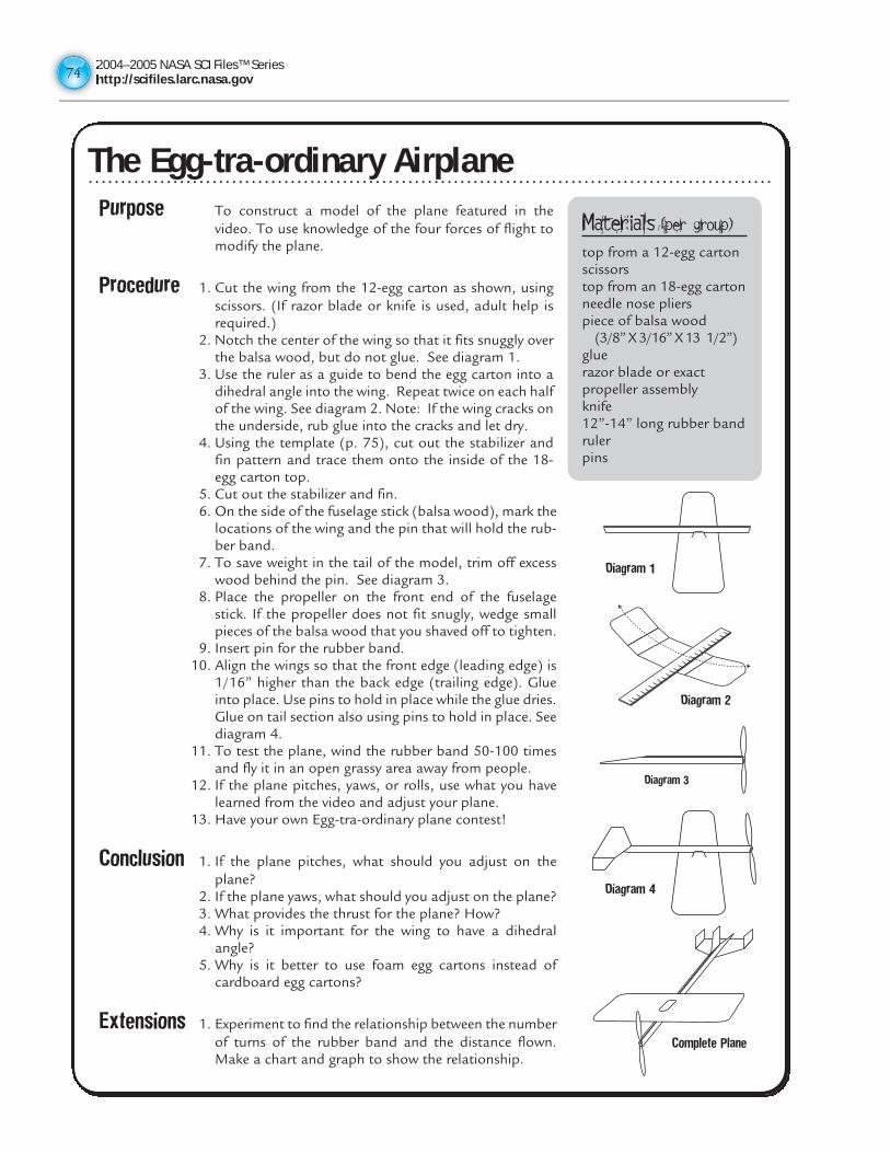
2004–2005 NASA SCI Files™ Serieshttp://scifiles.larc.nasa.gov7474
The Egg-tra-ordinary AirplanePurpose To construct a model of the plane featured in the
video. To use knowledge of the four forces of flight tomodify the plane.
Procedure 1. Cut the wing from the 12-egg carton as shown, usingscissors. (If razor blade or knife is used, adult help isrequired.)
2. Notch the center of the wing so that it fits snuggly overthe balsa wood, but do not glue. See diagram 1.
3. Use the ruler as a guide to bend the egg carton into adihedral angle into the wing. Repeat twice on each halfof the wing. See diagram 2. Note: If the wing cracks onthe underside, rub glue into the cracks and let dry.
4. Using the template (p. 75), cut out the stabilizer andfin pattern and trace them onto the inside of the 18-egg carton top.
5. Cut out the stabilizer and fin.6. On the side of the fuselage stick (balsa wood), mark the
locations of the wing and the pin that will hold the rub-ber band.
7. To save weight in the tail of the model, trim off excesswood behind the pin. See diagram 3.
8. Place the propeller on the front end of the fuselagestick. If the propeller does not fit snugly, wedge smallpieces of the balsa wood that you shaved off to tighten.
9. Insert pin for the rubber band.10. Align the wings so that the front edge (leading edge) is
1/16” higher than the back edge (trailing edge). Glueinto place. Use pins to hold in place while the glue dries.Glue on tail section also using pins to hold in place. Seediagram 4.
11. To test the plane, wind the rubber band 50-100 timesand fly it in an open grassy area away from people.
12. If the plane pitches, yaws, or rolls, use what you havelearned from the video and adjust your plane.
13. Have your own Egg-tra-ordinary plane contest!
Conclusion 1. If the plane pitches, what should you adjust on theplane?
2. If the plane yaws, what should you adjust on the plane?3. What provides the thrust for the plane? How?4. Why is it important for the wing to have a dihedral
angle?5. Why is it better to use foam egg cartons instead of
cardboard egg cartons?
Extensions 1. Experiment to find the relationship between the numberof turns of the rubber band and the distance flown.Make a chart and graph to show the relationship.
Diagram 1
Diagram 2
Diagram 3
Diagram 4
Complete Plane
Materials (per group)top from a 12-egg cartonscissorstop from an 18-egg cartonneedle nose plierspiece of balsa wood
(3/8” X 3/16” X 13 1/2”)gluerazor blade or exact propeller assemblyknife12”-14” long rubber bandrulerpins
The Egg-tra-ordinary Airplane
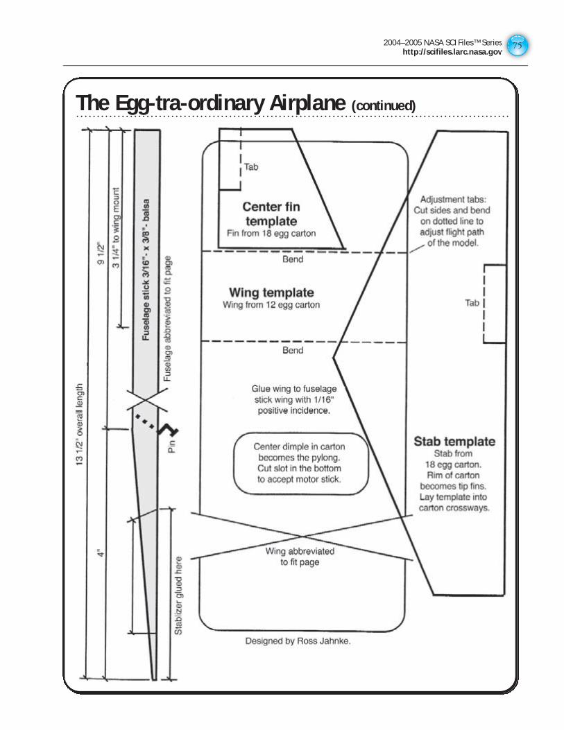
2004–2005 NASA SCI Files™ Serieshttp://scifiles.larc.nasa.gov
75
The Egg-tra-ordinary Airplane (continued)The Egg-tra-ordinary Airplane (continued)
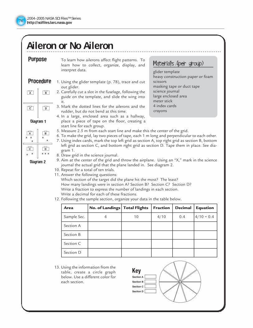
2004–2005 NASA SCI Files™ Serieshttp://scifiles.larc.nasa.gov7676
Aileron or No AileronPurpose To learn how ailerons affect flight patterns. To
learn how to collect, organize, display, andinterpret data.
Procedure 1. Using the glider template (p. 78), trace and cutout glider.
2. Carefully cut a slot in the fuselage, following theguide on the template, and slide the wing intoit.
3. Mark the dotted lines for the ailerons and therudder, but do not bend at this time.
4. In a large, enclosed area such as a hallway,place a piece of tape on the floor, creating astart line for each group.
5. Measure 2.5 m from each start line and make this the center of the grid. 6. To make the grid, lay two pieces of tape, each 1 m long and perpendicular to each other. 7. Using index cards, mark the top left grid as section A, top right grid as section B, bottom
left grid as section C, and bottom right grid as section D. Tape them in place. See dia-gram 1.
8. Draw grid in the science journal.9. Aim at the center of the grid and throw the airplane. Using an “X,” mark in the science
journal the actual grid that the plane landed in. See diagram 2.10. Repeat for a total of ten trials.11. Answer the following questions:
Which section of the target did the plane hit the most? The least?How many landings were in section A? Section B? Section C? Section D? Write a fraction to express the number of landings in each section.Write a decimal for each of these fractions.
12. Following the sample section, organize your data in the table below.
13. Using the information from thetable, create a circle graphbelow. Use a different color foreach section.
Materials (per group)glider templateheavy construction paper or foamscissorsmasking tape or duct tapescience journallarge enclosed areameter stick4 index cardscrayons
A B
DC
Diagram 1
A B
DC
x x x
x x xx
x
x
x
Diagram 2
Area No. of Landings Total Flights Fraction Decimal Equation
Sample Sec. 4 10 4/10 0.4 4/10 = 0.4
Section A
Section B
Section C
Section D
Aileron or No Aileron
2004–2005 NASA SCI Files™ Serieshttp://scifiles.larc.nasa.gov
77
Aileron or No Aileron (continued)14. Discuss and analyze the data.15. Discuss the purpose of ailerons and rudders on airplanes.16. Predict how the landing patterns will change when the ailerons are bent.17. Bend and fold the ailerons on the wing so that one aileron is bent up and one is bent
down. Repeat steps 8-13.18. Predict how the landing patterns will change when the rudder is bent.19. Bend and fold the rudder on the tail and repeat steps 8-13.
Conclusion 1. What effect, if any, did the ailerons have on the landing patterns?2. What effect, if any, did the rudder have on the landing patterns?3. Explain any similarities or differences in your graphs.4. Using the graphs, what conclusions can be made about how ailerons affected the direc-
tion of the planes?5. What happens when air hits the ailerons? How would pilots use ailerons on real planes?
Extensions 1. Test various designs of paper airplanes.2. Test various positions of the ailerons and rudders.
Aileron or No Aileron (continued)
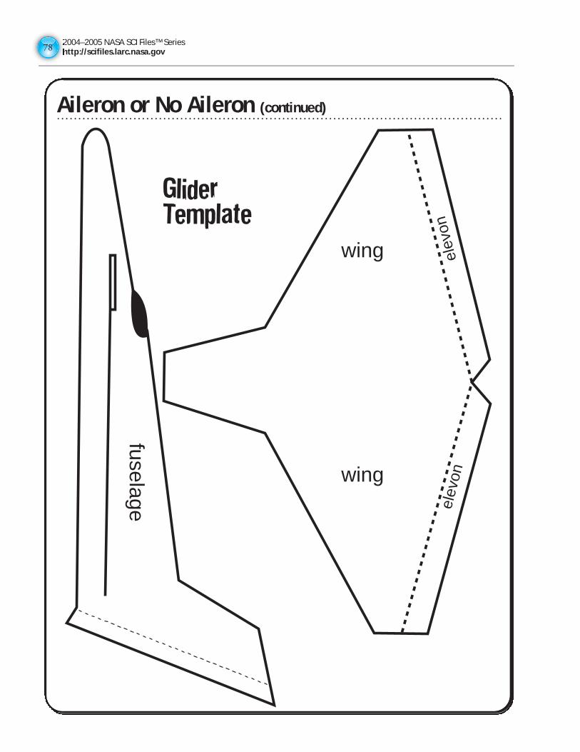
2004–2005 NASA SCI Files™ Serieshttp://scifiles.larc.nasa.gov7878
Aileron or No Aileron (continued)
wing
wingel
evon
elev
onfuselage
GliderTemplate
Aileron or No Aileron (continued)
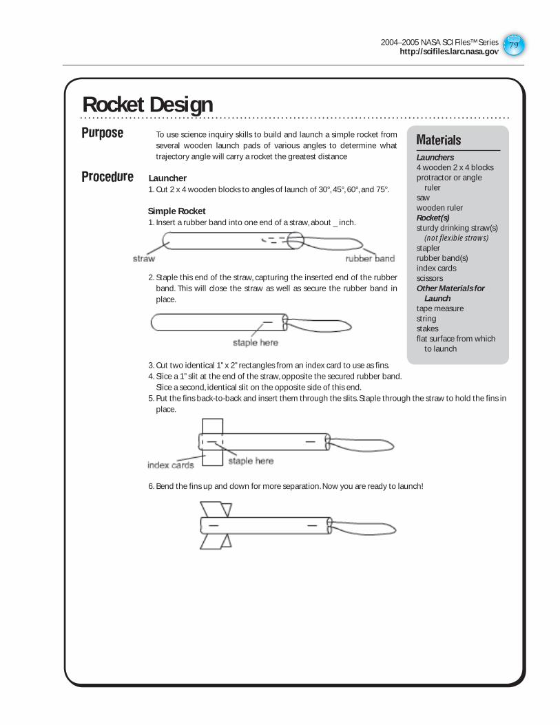
2004–2005 NASA SCI Files™ Serieshttp://scifiles.larc.nasa.gov
79
Rocket DesignPurpose To use science inquiry skills to build and launch a simple rocket from
several wooden launch pads of various angles to determine what trajectory angle will carry a rocket the greatest distance
Procedure Launcher 1. Cut 2 x 4 wooden blocks to angles of launch of 30°, 45°, 60°, and 75°.
Simple Rocket 1. Insert a rubber band into one end of a straw, about _ inch.
2. Staple this end of the straw, capturing the inserted end of the rubber band. This will close the straw as well as secure the rubber band in place.
3. Cut two identical 1” x 2” rectangles from an index card to use as fins. 4. Slice a 1” slit at the end of the straw, opposite the secured rubber band.
Slice a second, identical slit on the opposite side of this end. 5. Put the fins back-to-back and insert them through the slits. Staple through the straw to hold the fins in
place.
6. Bend the fins up and down for more separation. Now you are ready to launch!
Materials
Launchers 4 wooden 2 x 4 blocksprotractor or angle
rulersawwooden rulerRocket(s) sturdy drinking straw(s)
(not flexible straws)staplerrubber band(s)index cardsscissorsOther Materials for
Launch tape measurestringstakesflat surface from which
to launch
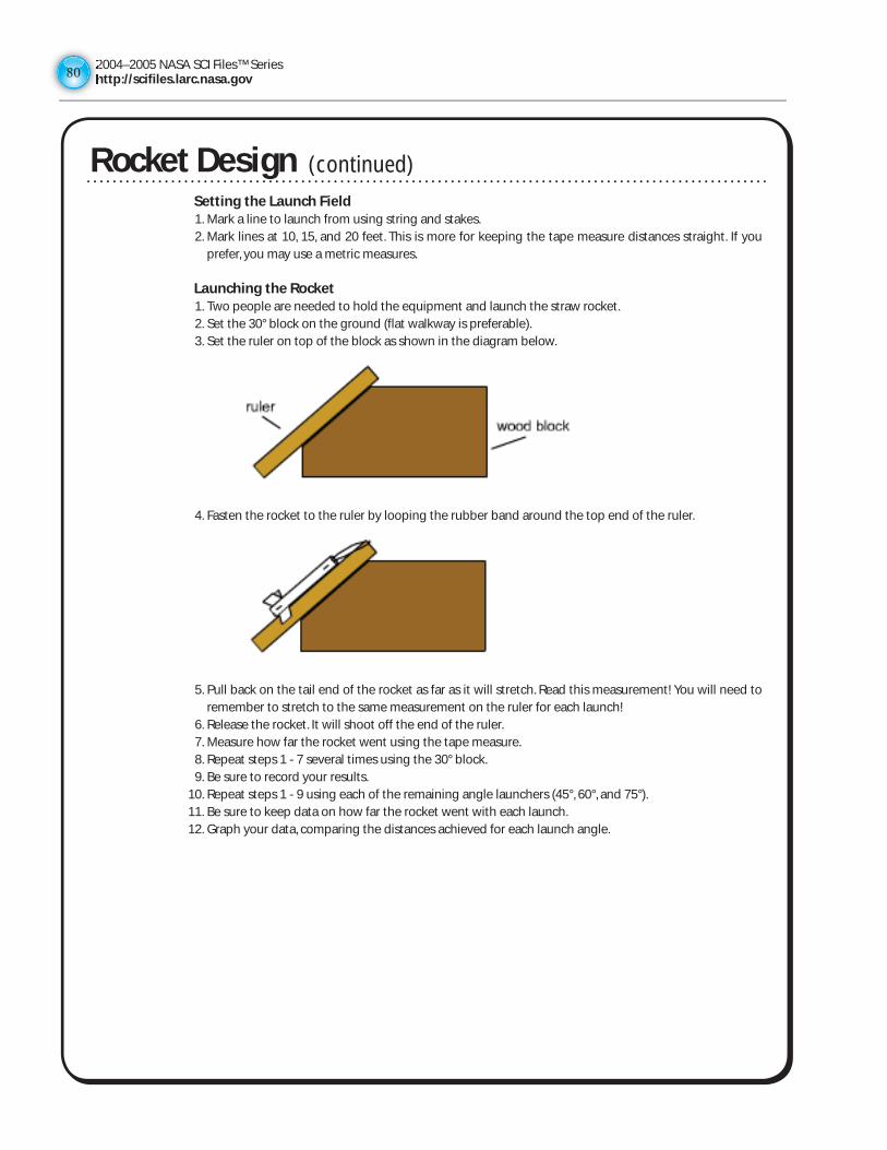
2004–2005 NASA SCI Files™ Serieshttp://scifiles.larc.nasa.gov8080
Rocket Design Setting the Launch Field 1. Mark a line to launch from using string and stakes. 2. Mark lines at 10, 15, and 20 feet. This is more for keeping the tape measure distances straight. If you
prefer, you may use a metric measures. Launching the Rocket 1. Two people are needed to hold the equipment and launch the straw rocket. 2. Set the 30° block on the ground (flat walkway is preferable). 3. Set the ruler on top of the block as shown in the diagram below.
4. Fasten the rocket to the ruler by looping the rubber band around the top end of the ruler.
5. Pull back on the tail end of the rocket as far as it will stretch. Read this measurement! You will need to remember to stretch to the same measurement on the ruler for each launch!
6. Release the rocket. It will shoot off the end of the ruler. 7. Measure how far the rocket went using the tape measure. 8. Repeat steps 1 - 7 several times using the 30° block. 9. Be sure to record your results. 10. Repeat steps 1 - 9 using each of the remaining angle launchers (45°, 60°, and 75°). 11. Be sure to keep data on how far the rocket went with each launch. 12. Graph your data, comparing the distances achieved for each launch angle.
(continued)
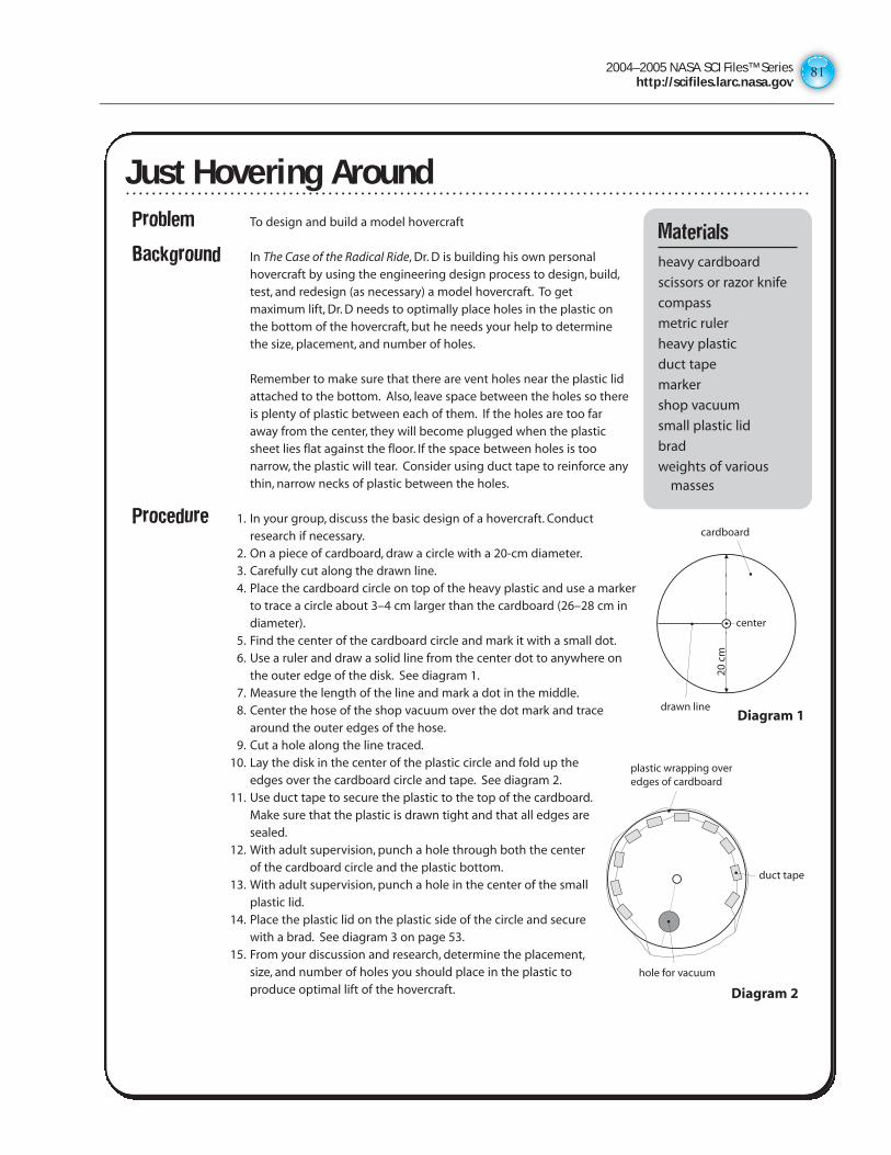
2004–2005 NASA SCI Files™ Serieshttp://scifiles.larc.nasa.gov
81
Just Hovering Around
Problem To design and build a model hovercraft
Background In The Case of the Radical Ride, Dr. D is building his own personalhovercraft by using the engineering design process to design, build,test, and redesign (as necessary) a model hovercraft. To getmaximum lift, Dr. D needs to optimally place holes in the plastic onthe bottom of the hovercraft, but he needs your help to determinethe size, placement, and number of holes.
Remember to make sure that there are vent holes near the plastic lidattached to the bottom. Also, leave space between the holes so thereis plenty of plastic between each of them. If the holes are too faraway from the center, they will become plugged when the plasticsheet lies flat against the floor. If the space between holes is toonarrow, the plastic will tear. Consider using duct tape to reinforce anythin, narrow necks of plastic between the holes.
Procedure 1. In your group, discuss the basic design of a hovercraft. Conductresearch if necessary.
2. On a piece of cardboard, draw a circle with a 20-cm diameter.3. Carefully cut along the drawn line.4. Place the cardboard circle on top of the heavy plastic and use a marker
to trace a circle about 3–4 cm larger than the cardboard (26–28 cm indiameter).
5. Find the center of the cardboard circle and mark it with a small dot.6. Use a ruler and draw a solid line from the center dot to anywhere on
the outer edge of the disk. See diagram 1.7. Measure the length of the line and mark a dot in the middle.8. Center the hose of the shop vacuum over the dot mark and trace
around the outer edges of the hose.9. Cut a hole along the line traced.
10. Lay the disk in the center of the plastic circle and fold up theedges over the cardboard circle and tape. See diagram 2.
11. Use duct tape to secure the plastic to the top of the cardboard.Make sure that the plastic is drawn tight and that all edges aresealed.
12. With adult supervision, punch a hole through both the centerof the cardboard circle and the plastic bottom.
13. With adult supervision, punch a hole in the center of the smallplastic lid.
14. Place the plastic lid on the plastic side of the circle and securewith a brad. See diagram 3 on page 53.
15. From your discussion and research, determine the placement,size, and number of holes you should place in the plastic toproduce optimal lift of the hovercraft.
Materials
heavy cardboard
scissors or razor knife
compass
metric ruler
heavy plastic
duct tape
marker
shop vacuum
small plastic lid
brad
weights of variousmasses
cardboard
center
drawn line20
cm
duct tape
hole for vacuum
plastic wrapping over edges of cardboard
Diagram 1
Diagram 2
Just Hovering Around
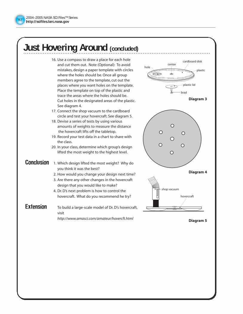
2004–2005 NASA SCI Files™ Serieshttp://scifiles.larc.nasa.gov8282
Just Hovering Around (concluded)
16. Use a compass to draw a place for each holeand cut them out. Note (Optional): To avoidmistakes, design a paper template with circleswhere the holes should be. Once all groupmembers agree to the template, cut out theplaces where you want holes on the template.Place the template on top of the plastic andtrace the areas where the holes should be.Cut holes in the designated areas of the plastic.See diagram 4.
17. Connect the shop vacuum to the cardboardcircle and test your hovercraft. See diagram 5.
18. Devise a series of tests by using variousamounts of weights to measure the distancethe hovercraft lifts off the tabletop.
19. Record your test data in a chart to share withthe class.
20. In your class, determine which group’s designlifted the most weight to the highest level.
Conclusion 1. Which design lifted the most weight? Why do
you think it was the best?
2. How would you change your design next time?
3. Are there any other changes in the hovercraft
design that you would like to make?
4. Dr. D’s next problem is how to control the
hovercraft. What do you recommend he try?
Extension To build a large-scale model of Dr. D’s hovercraft,
visit
http://www.amasci.com/amateur/hovercft.html
center
plastichole
plastic lid
brad
cardboard disk
hovercraft
shop vacuum
Diagram 3
Diagram 4
Diagram 5
Just Hovering Around (concluded)
2004–2005 NASA SCI Files™ Serieshttp://scifiles.larc.nasa.gov
83
ANSWER KEY
Blended Wing Body
1. Answers will vary.
Acrobat Glider
1-2. Answers will vary.
3. The amount of bend to the foam.
4. Answers will vary.
The Egg-tra-ordinary Plane
1. If the plane pitches up, you should bend the stabilizer tab down. If it pitches down, bend the tab up.
2. If the plane yaws to the right or left, bend the rudder tab to the opposite direction.
3. The winding of the rubber band provides the thrust for the plane. As you wind the rubber band, you are storing potential energy. When the propeller is released, the energy in the rubber band is released and causes the propeller to turn. As the propeller turns, its shape creates airflow over the propellers, creating a forward force pulling the plane through the air. As the plane is pulled through the air, the air flows over the wings, creating lift.
4. It is important for a plane to have a dihedral angle to stabilize the plane as it is turning. The angle gives the pilot more control as he/she turns the plane.
5. Foam egg cartons are lighter in weight and will therefore require less thrust to go farther.
Aileron or No Aileron
1. Answers will vary.
2. Answers will vary.
3. Answers will vary.
4. Answers will vary.
5. When the air hits the aileron, it is deflected in the direction the aileron is pointing, causing the air to slow down. The slowing down of the air creates a force that enables the plane to turn or slow down.Think of it in terms of running across a field with your arms outstretched and hitting a light post with your left arm. The force of the pole hitting your arm deflects your body in the opposite direction. The air hitting the aileron also causes the plane to go in the opposite direction, thus enabling a pilot to turn the plane. A pilot will use ailerons to turn the plane, to slow down, to control the pitch, and to land.
Just Hovering Around
1–4. Answers will vary.
Physical Science & Engineering Design
CREATE YOUR OWN
SECTION IV
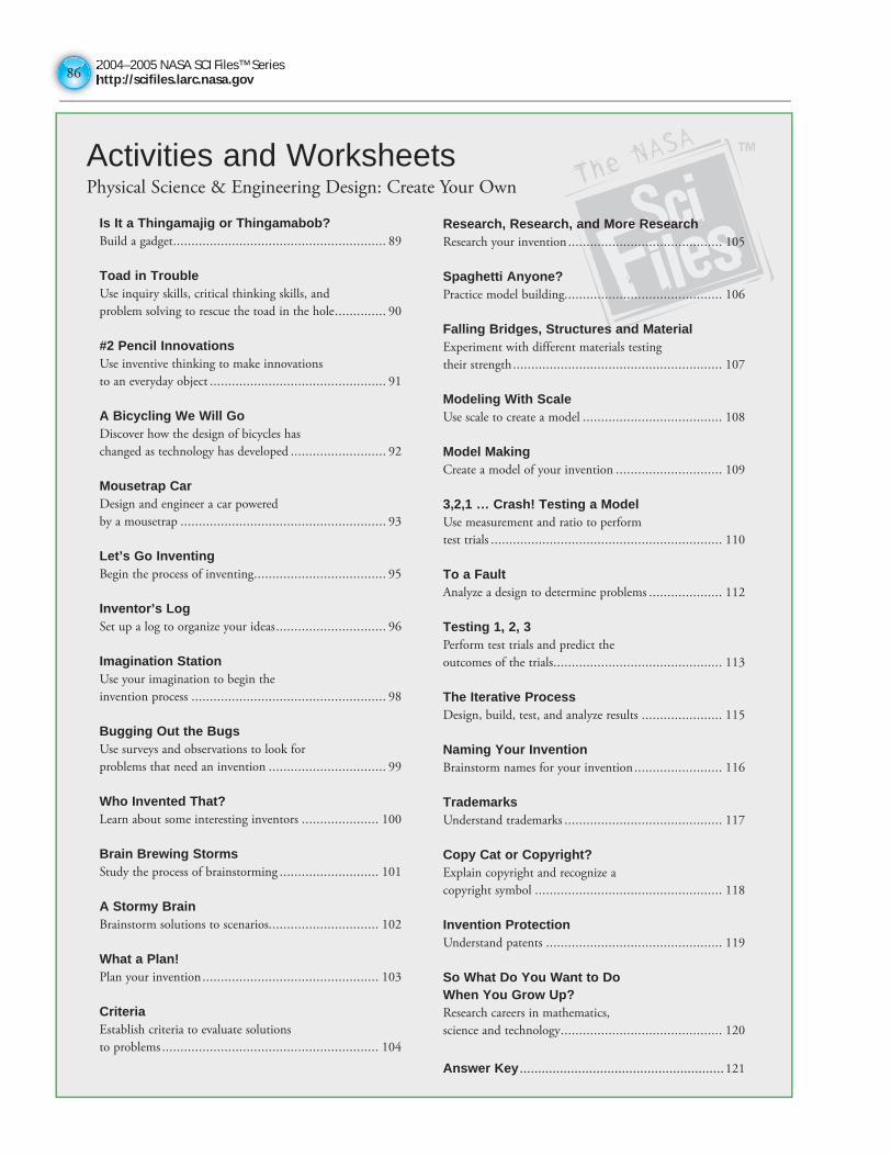
2004–2005 NASA SCI Files™ Serieshttp://scifiles.larc.nasa.gov8686
Activities and WorksheetsPhysical Science & Engineering Design: Create Your Own
Is It a Thingamajig or Thingamabob?Build a gadget .......................................................... 89
Toad in TroubleUse inquiry skills, critical thinking skills, and
problem solving to rescue the toad in the hole .............. 90
#2 Pencil InnovationsUse inventive thinking to make innovations
to an everyday object ................................................ 91
A Bicycling We Will GoDiscover how the design of bicycles has
changed as technology has developed .......................... 92
Mousetrap CarDesign and engineer a car powered
by a mousetrap ........................................................ 93
Let’s Go InventingBegin the process of inventing .................................... 95
Inventor’s LogSet up a log to organize your ideas .............................. 96
Imagination StationUse your imagination to begin the
invention process ..................................................... 98
Bugging Out the BugsUse surveys and observations to look for
problems that need an invention ................................ 99
Who Invented That?Learn about some interesting inventors ..................... 100
Brain Brewing StormsStudy the process of brainstorming ........................... 101
A Stormy BrainBrainstorm solutions to scenarios .............................. 102
What a Plan!Plan your invention ................................................ 103
CriteriaEstablish criteria to evaluate solutions
to problems ........................................................... 104
Research, Research, and More ResearchResearch your invention .......................................... 105
Spaghetti Anyone?Practice model building........................................... 106
Falling Bridges, Structures and MaterialExperiment with different materials testing
their strength ......................................................... 107
Modeling With ScaleUse scale to create a model ...................................... 108
Model MakingCreate a model of your invention ............................. 109
3,2,1 … Crash! Testing a ModelUse measurement and ratio to perform
test trials ............................................................... 110
To a FaultAnalyze a design to determine problems .................... 112
Testing 1, 2, 3Perform test trials and predict the
outcomes of the trials .............................................. 113
The Iterative ProcessDesign, build, test, and analyze results ...................... 115
Naming Your InventionBrainstorm names for your invention ........................ 116
TrademarksUnderstand trademarks ........................................... 117
Copy Cat or Copyright?Explain copyright and recognize a
copyright symbol ................................................... 118
Invention ProtectionUnderstand patents ................................................ 119
So What Do You Want to Do When You Grow Up?Research careers in mathematics,
science and technology ............................................ 120
Answer Key ........................................................121
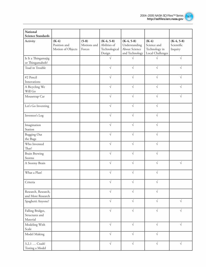
2004–2005 NASA SCI Files™ Serieshttp://scifiles.larc.nasa.gov
87
National Science Standards
Activity (K-4)Position and
Motion of Objects
(5-8)Motions and
Forces
(K-4, 5-8)Abilities of
Technological
Design
(K-4, 5-8) Understanding
About Science
and Technology
(K-4) Science and
Technology in
Local Challenges
(K-4, 5-8)Scientifi c
Inquiry
Is It a Th ingamajig
or Th ingamabob?
√ √ √ √
Toad in Trouble √ √ √ √
#2 Pencil
Innovations
√ √ √ √
A Bicycling We
Will Go
√ √ √ √
Mousetrap Car √ √ √ √
Let’s Go Inventing √ √ √
Inventor’s Log √ √ √
Imagination
Station
√ √ √
Bugging Out
the Bugs
√ √ √
Who Invented
Th at?
√ √ √
Brain Brewing
Storms
√ √ √
A Stormy Brain √ √ √ √
What a Plan! √ √ √
Criteria √ √ √
Research, Research,
and More Research
√ √ √
Spaghetti Anyone? √ √ √ √
Falling Bridges,
Structures and
Material
√ √ √ √
Modeling With
Scale
√ √ √ √
Model Making √ √ √
3,2,1 … Crash!
Testing a Model
√ √ √ √
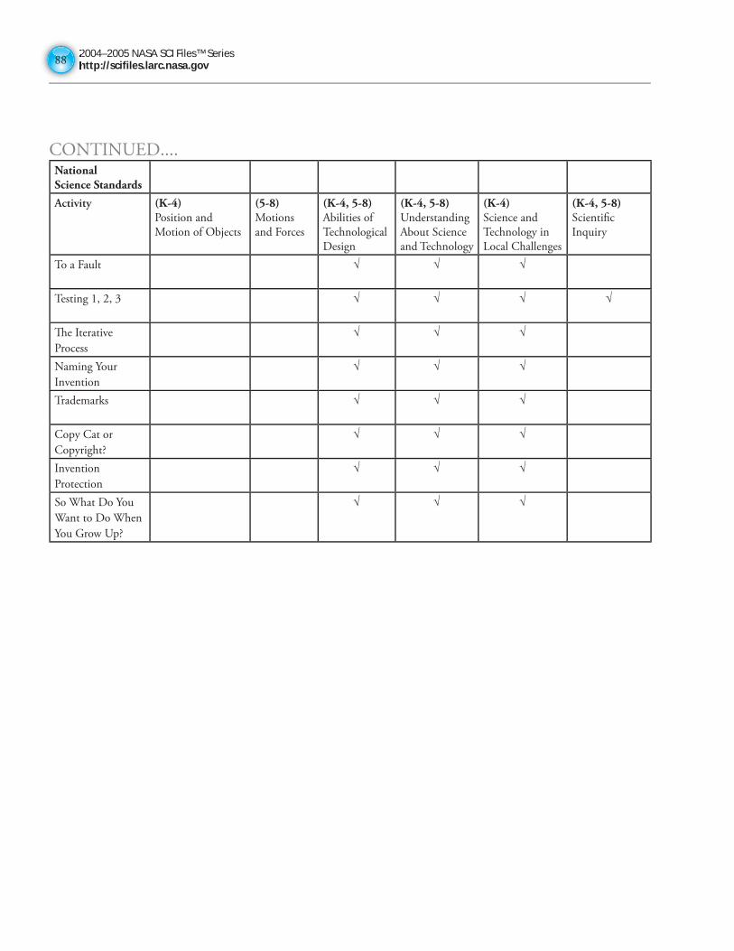
2004–2005 NASA SCI Files™ Serieshttp://scifiles.larc.nasa.gov8888
CONTINUED....National Science Standards
Activity (K-4)Position and
Motion of Objects
(5-8)Motions
and Forces
(K-4, 5-8)Abilities of
Technological
Design
(K-4, 5-8) Understanding
About Science
and Technology
(K-4) Science and
Technology in
Local Challenges
(K-4, 5-8)Scientifi c
Inquiry
To a Fault √ √ √
Testing 1, 2, 3 √ √ √ √
Th e Iterative
Process
√ √ √
Naming Your
Invention
√ √ √
Trademarks √ √ √
Copy Cat or
Copyright?
√ √ √
Invention
Protection
√ √ √
So What Do You
Want to Do When
You Grow Up?
√ √ √
2004–2005 NASA SCI Files™ Serieshttp://scifiles.larc.nasa.gov
89
Purpose To discover that inventing is fun while building a gadget
Procedure 1. Place your group’s junk on the table.
2. Try fitting the junk together in different ways.
3. Discuss various ideas of how to connect the junk to develop an
idea for a thingamajig.
4. Once you have an idea, start to build your thingamajig. As you
work on it, don’t be afraid to take it apart and start over again
if you think of a better way of putting it together. Also, remember that your thingamajig
doesn’t have to work. You can always use your imagination to pretend that it does.
5. Write a newspaper article announcing your new invention to the public. Be sure to describe
its parts, what each one is used for, and the purpose of the thingamajig.
6. Illustrate your article by drawing your thingamajig.
Extension Look for other thingamajigs around you. Look in attics, basements, garages, and even
junkyards. Sketch the ones you find and make a book of thingamajigs. If you don’t know
what the thingamajig was used for, create a use for it! Create your own categories for the
thingamajigs and sort them.
Is It a Thingamajig or Thingamabob?Materials
discarded “junk”stringtapeglue
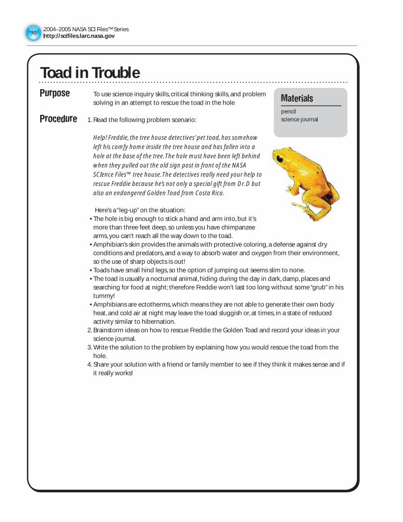
2004–2005 NASA SCI Files™ Serieshttp://scifiles.larc.nasa.gov9090
Purpose To use science inquiry skills, critical thinking skills, and problem solving in an attempt to rescue the toad in the hole
Procedure 1. Read the following problem scenario:
Help! Freddie, the tree house detectives’ pet toad, has somehow
left his comfy home inside the tree house and has fallen into a
hole at the base of the tree. The hole must have been left behind
when they pulled out the old sign post in front of the NASA
SCIence Files™ tree house. The detectives really need your help to
rescue Freddie because he’s not only a special gift from Dr. D but
also an endangered Golden Toad from Costa Rica.
Here’s a “leg-up” on the situation: • The hole is big enough to stick a hand and arm into, but it’s
more than three feet deep, so unless you have chimpanzee arms, you can’t reach all the way down to the toad.
• Amphibian’s skin provides the animals with protective coloring, a defense against dry conditions and predators, and a way to absorb water and oxygen from their environment, so the use of sharp objects is out!
• Toads have small hind legs, so the option of jumping out seems slim to none. • The toad is usually a nocturnal animal, hiding during the day in dark, damp, places and
searching for food at night; therefore Freddie won’t last too long without some “grub” in his tummy!
• Amphibians are ectotherms, which means they are not able to generate their own body heat, and cold air at night may leave the toad sluggish or, at times, in a state of reduced activity similar to hibernation.
2. Brainstorm ideas on how to rescue Freddie the Golden Toad and record your ideas in your science journal.
3. Write the solution to the problem by explaining how you would rescue the toad from the hole.
4. Share your solution with a friend or family member to see if they think it makes sense and if it really works!
Toad in TroubleMaterials
pencilscience journal
2004–2005 NASA SCI Files™ Serieshttp://scifiles.larc.nasa.gov
91
Purpose To understand the difference between potential and kinetic energy
Procedure 1. Observe an ordinary #2 pencil.
2. Think about these questions and record your responses in your
science journal:
• What functions can a #2 pencil fulfill?
• What differences exist between a pencil and a pen?
• What improvements can be made to a #2 pencil?
• What is the #2 pencil’s best feature?
• What new features can be added to the #2 pencil to make it more useful?
3. In your science journal, draw a picture of what your new and improved #2 pencil would
look like. Label all parts!
4. In your science journal, brainstorm ideas of what a 22nd century pencil will look like; then
draw and label it.
5. Share your newly innovated #2 pencil and 22nd century pencil with a friend and explain
why they are better than the original!
Extension Visit your local library and check out the book, The Pencil: A History of Design and Circumstances by Henry Petroski, to learn the history behind the pencil
#2 Pencil InnovationsMaterials
#2 pencilscience journalcolored pencils
2004–2005 NASA SCI Files™ Serieshttp://scifiles.larc.nasa.gov9292
Purpose To discover how the design of bicycles has changed over time as technology has developed
Background Nobody knows exactly when the first bike was invented, but in the late 1700s there was a “hobbyhorse” that had wooden wheels, but no pedals. Their riders had to ride it by pushing it with their feet, and if they wanted to get off, they had to drag their feet until it stopped. Needless to say, only really strong people were able to ride a “hobbyhorse.” Through the years as technology became better, the bicycle began to change. Today there are many styles and kinds of bicycles to choose from. Bicycles are not only used for riding pleasure, but have also been adapted to do various jobs, such as a street sweeper and ice cream cart. You may even use yours for a paper route.
Web Sites • Japanese Bicycle History Research ClubExplore the history of bicycling in Japan. Includes photo galleries, articles and more.http://www.eva.hi-ho.ne.jp/ootsu/
• National Bicycle History of America Association (NBHAA)Web site dedicated to the identification, cataloging, and restoration of American bikes from 1920-1965.http://members.aol.com/oldbicycle/
• Bicycles, History, Beauty, FantasyThis web site has great pictures and historical accounts of bicycles from 1863 to 1901.http://users.rcn.com/eye/bicycles.html
Procedure 1. Use the various print and internet resources to trace the history of the bicycle. 2. Write a one to two page report showing how technology changed the way the bicycle
looks and works. Describe how the features of the various designs of the bicycle help to accomplish its purpose.
3. If possible, cut and paste pictures from various web sites for your report. 4. Present your report to the class.
A Bicycling We Will GoMaterials
printed resourcesencyclopediasinternetscience journal
2004–2005 NASA SCI Files™ Serieshttp://scifiles.larc.nasa.gov
93
Problem To design and engineer a car solely powered by one standard-sized mousetrap that will travel the greatest distance
Teachers Note• Before starting the design challenge, students should have a
good understanding of simple machines, force and motion,and the design process. To learn more about these topics,check out The Case of the Powerful Pulleys and The Case of theWright Invention on the NASA SCI Files™ web site http://scifiles.larc.nasa.gov Students can also conduct aweb search to research other mousetrap car designs.
• Rubrics for assessment can be found on the NASA SCI Files™web site in the Educators area by clicking on Tools in themenu bar and then choosing Instructional Tools.
• Check out NASA LIVE™ http://live.larc.nasa.gov to learnmore about FREE videoconferencing programs that connectyour students with NASA engineers, scientists, and specialists.
The time required varies, depending on how much of theproject is assigned for homework. If done completely in class,it should take about six 45-minute class periods.
** To be determined by teacher and/or student. Various objects such as foam material meat trays, Legos®,modified toy cars, balsa wood, washers, and other objects can be brought from home and used to build amousetrap car. Be creative! To make the competition fair, provide multiple items in a pool of resources fromwhich students can choose.
Design Rules 1. All teams must use the same type of mousetrap.2. Only the team members can construct the mousetrap car. (No help from parents or other
adults!)3. The mousetrap must be the sole source of propulsion, and it must move forward with the
vehicle.4. The cars must have a minimum of three wheels that remain on the ground at all times.5. A mousetrap’s spring may be removed only to adjust the length of the lever arm.6. Vehicles must be self-starting and steer themselves.
Procedure 1. In your group, discuss the design challenge and brainstorm for various mousetrap cardesign ideas. List your ideas in the Design Log.
2. Reach a consensus about which design is the best.3. Draw a diagram of the chosen design and be sure to label all parts.4. Discuss the design and conduct research to answer any design questions.5. Make a list of materials and collect the ones necessary for your design.6. Work as a group to construct your vehicle.7. Test your vehicle and make any necessary design changes.8. Repeat step 7 until your vehicle is ready for its first race.
Mousetrap Car
Materials
Design Log (p. 22)1 standard mousetrapstringrubber bandsmaterial for axles
(dowel rods,skewers, straws)
wheels (lids, compactdisks, butter tub lids)
glue low temperature glue
gun (optional)scissorsgraph papermeter stickmasking tapeother**
Mousetrap Car
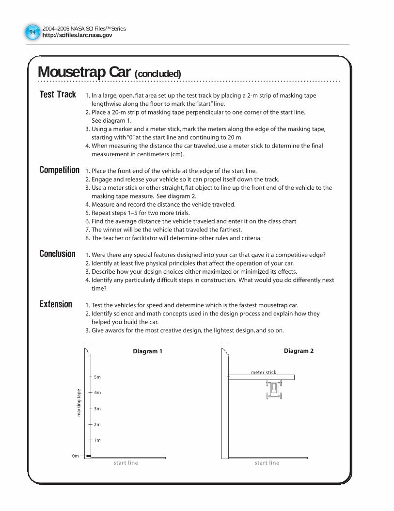
2004–2005 NASA SCI Files™ Serieshttp://scifiles.larc.nasa.gov9494
Test Track 1. In a large, open, flat area set up the test track by placing a 2-m strip of masking tapelengthwise along the floor to mark the “start” line.
2. Place a 20-m strip of masking tape perpendicular to one corner of the start line.See diagram 1.
3. Using a marker and a meter stick, mark the meters along the edge of the masking tape,starting with “0” at the start line and continuing to 20 m.
4. When measuring the distance the car traveled, use a meter stick to determine the finalmeasurement in centimeters (cm).
Competition 1. Place the front end of the vehicle at the edge of the start line.2. Engage and release your vehicle so it can propel itself down the track.3. Use a meter stick or other straight, flat object to line up the front end of the vehicle to the
masking tape measure. See diagram 2.4. Measure and record the distance the vehicle traveled.5. Repeat steps 1–5 for two more trials.6. Find the average distance the vehicle traveled and enter it on the class chart.7. The winner will be the vehicle that traveled the farthest.8. The teacher or facilitator will determine other rules and criteria.
Conclusion 1. Were there any special features designed into your car that gave it a competitive edge?2. Identify at least five physical principles that affect the operation of your car.3. Describe how your design choices either maximized or minimized its effects.4. Identify any particularly difficult steps in construction. What would you do differently next
time?
Extension 1. Test the vehicles for speed and determine which is the fastest mousetrap car.2. Identify science and math concepts used in the design process and explain how they
helped you build the car.3. Give awards for the most creative design, the lightest design, and so on.
mar
kin
g t
ape
start line
1m
2m
3m
4m
5m
start line
meter stick
0m
Diagram 1 Diagram 2
Mousetrap Car (concluded)Mousetrap Car (concluded)
2004–2005 NASA SCI Files™ Serieshttp://scifiles.larc.nasa.gov
95
Let’s Go InventingInventing is fun and exciting, and everyone can be an inventor! An inventor is someone who thinks of new waysto solve problems in the home, community, or even the world. These solutions are called inventions. Aninvention is a new discovery, or it can be a new product. It can also be a process—a new way of doing things.Inventions come about in many ways. Most of the time, inventions happen because someone had to solve aproblem, but sometimes inventions are the result of accidents. No matter how an invention is created, it isimportant that you keep careful records to make sure that you get credit for first having the idea.
There are a few simple steps to follow in the invention process. Use the checklist below to make sure that youare staying on track and protecting your invention!
❑ Keep a log. All inventors keep a log to record their work and their ideas. Keeping a log will prove that youhad an idea first, and it will help you plan your invention.
❑ Use your imagination. Think wild and crazy thoughts. Remember that no idea is too silly. Everyonelaughed at the Wright brothers and said that man would never fly. Good thing the Wright brothers didn’tget discouraged!
❑ Look for problems that need solving. Look around you to find things that bug you or for things that wouldmake life easier or better.
❑ Plan and design your invention. Careful design is important in the invention process. This is the time tobrainstorm for ideas and to evaluate them.
❑ Research your invention to make sure that it has not already been invented and that it will work.
❑ Draw your invention. Make a detailed drawing of your invention so others will understand how yourinvention works.
❑ Make a model of your invention.
❑ Test your invention. If you have a working model, test it to see if it works as planned. If not, do moreresearch, redesign it, and test it again. This procedure is called an iterative process.
❑ Name your invention. Every invention needs a name!
❑ Patent your invention. If you think your invention is one that others would want, contact the U.S. PatentOffice.
❑ Share your inventions with others!
Let’s Go Inventing
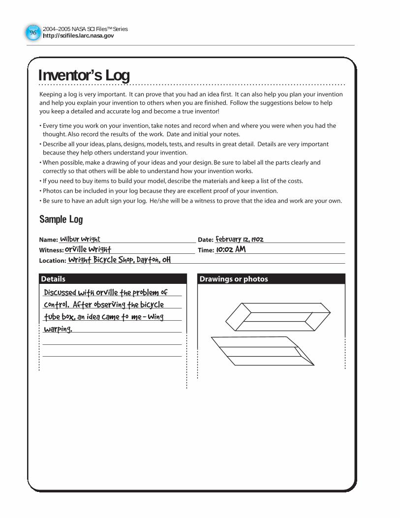
2004–2005 NASA SCI Files™ Serieshttp://scifiles.larc.nasa.gov9696
Inventor’s LogKeeping a log is very important. It can prove that you had an idea first. It can also help you plan your inventionand help you explain your invention to others when you are finished. Follow the suggestions below to helpyou keep a detailed and accurate log and become a true inventor!
• Every time you work on your invention, take notes and record when and where you were when you had thethought. Also record the results of the work. Date and initial your notes.
• Describe all your ideas, plans, designs, models, tests, and results in great detail. Details are very importantbecause they help others understand your invention.
• When possible, make a drawing of your ideas and your design. Be sure to label all the parts clearly andcorrectly so that others will be able to understand how your invention works.
• If you need to buy items to build your model, describe the materials and keep a list of the costs.
• Photos can be included in your log because they are excellent proof of your invention.
• Be sure to have an adult sign your log. He/she will be a witness to prove that the idea and work are your own.
Sample Log
Inventor’s Log
2004–2005 NASA SCI Files™ Serieshttp://scifiles.larc.nasa.gov
97
Inventor’s LogName: Date:
Witness: Time:
Location:
Details Drawings or photos
Inventor’s Log
2004–2005 NASA SCI Files™ Serieshttp://scifiles.larc.nasa.gov9898
Imagination StationAnyone can be an inventor. All you need is a little imagination, ingenuity, and hard work. Your imagination isone of your most precious assets. Before you begin the invention process, loosen up your imagination bytrying the activities below.
Take a Fantasy Journey
Have your partner close his/her eyes and read aloud the following fantasy journey.
Close your eyes and relax. Imagine yourself sitting on a beach. Watch the waves as they crash on the shore.Listen to the sound they make as they crash. Feel the Sun on your face. Do you hear the seagulls as theysearch for food? Imagine running your hands through the sand. How does it feel? Is it hot or cold, wet ordry, sticky or smooth? Imagine yourself building a sand castle. You wish you could see inside your castle.Suddenly, your body shrinks, and you are walking into the castle. What is inside? How many rooms arethere? Imagine the people who used to live in castles long ago. What were they like? Now, just as suddenlyas you shrank, you become big again. Your sand castle is wrecked. As you glance at the water, you noticethat it has changed color. Imagine, in vivid detail, the color of the water. What creatures would live in anocean that color? Imagine yourself swimming with them.
Now, slowly open your eyes and illustrate your fantasy journey below.
Imagine and write your own fantasy journey:
Imagination Station
2004–2005 NASA SCI Files™ Serieshttp://scifiles.larc.nasa.gov
99
Bugging Out the BugsEveryday we have things that “bug” us. These can either be problems that we encounter or they can be needsthat are not met. For example, if you want to take your dog for a walk, you will NEED a leash to keep him fromrunning away. Who invented the leash? Someone who needed one! If you wear glasses, it might really bugyou that they are always lost. You buy a strap that holds your glasses around your neck so that you can alwaysfind them. Who invented that strap? Someone who was bugged because they kept losing their glasses!Inventing is that simple. So lets get started!
Take a look around your home, school, and community to see what bugs you or what you need to make lifeeasier or more pleasant. Survey your family, friends, or classmates to see what bugs them and what needs theyhave. Don’t worry about solving the problem, that will come later. To get started, ask yourself these questions:
1. What bugs me the most?
At school:
At home:
During playtime or sports:
2. What chore or job can I make easier?
3. What thing(s) do I want to work better?
4. Can I make something easier to use?
5. Are there new ways to use things I already have?
Survey of family, friends, or classmates:
1. What bugs you the most?
2. What would make your job easier?
3. What is your biggest need?
4. What job or chore do you not want to do?
5. (Write your own questions.)
Bugging Out the Bugs
2004–2005 NASA SCI Files™ Serieshttp://scifiles.larc.nasa.gov100100
Who Invented That?Purpose To learn about famous and not so famous inventors and their
inventions
Procedure 1. Choose an inventor from the list below or pick one of your own.2. Research the inventor and take notes on important and interesting
facts about the person and the invention.3. Share the information with your class or family by performing a skit,
writing a report, creating a poster, or writing a newspaper article.
Inventors Geradus Mercator Robert Fulton Blaise PascalEvangelista Torricelli Christopher Cockerell Margaret KnightMaria Mayer Anders Celsius Isaac NewtonGalileo Galilei Grace Hopper Alva FisherHans Janssen Richard Drew Sophie GermainLeonardo da Vinci Elisha Otis Stephanie KwolekElmer Sperry George Eastman Sonya KovalevskyHenry Ford Erna Hoover Thomas EdisonArchimedes Albert Einstein Garfield WestonRuth Handler Dr. John Pemberton Clive SinclairFrank Epperson Bette Nesmith Graham Ivan SutherlandCharles Darrow
Notes
Materials
reference books,encyclopedias,and web sites
paperpencil
Who Invented That?
2004–2005 NASA SCI Files™ Serieshttp://scifiles.larc.nasa.gov
101
Brain Brewing StormsPurpose To study the process of thinking that enables inventors to
dream up new ideas
Procedure 1. Discuss the rules of brainstorming:2. Accept all ideas—there are no silly or bad ideas.3. Record all ideas.4. Produce a large number of ideas for a greater chance of finding
a “winner.”5. Dare to dream up wild and “far-out” ideas because they can
often become practical ideas.6. Set a time limit.7. Have one student in the group reach into the box and pull out an object.8. Set the timer and list all suggested ideas for possible uses of the object.9. After time is called, use the brainstorm web below to categorize your ideas. If you need more
space, use the back of this sheet.10. If time permits, repeat with other objects.
Conclusion 1. Which ideas seem the most logical? Why?
2. Which ideas seem the most useful? Why?
3. What criteria did you use to sort the ideas?
4. Were the ideas you listed first your most creative ideas? Why or why not?
5. Did any oddball ideas turn into useful ideas? How?
Materials
variety of junk objectsbox or bag for objectspencilpapertimer or clock
Brain Brewing Storms
2004–2005 NASA SCI Files™ Serieshttp://scifiles.larc.nasa.gov102102
A Stormy BrainPurpose To learn how to link ideas and questions together to form a
relationship
Background Brainstorming is fun and can be helpful when trying to solveproblems. It is a process of spontaneously thinking and sharingas many ideas as possible about a topic without beingjudgmental. Brainstorming is an important part of theproblem-solving process, and there are a few suggested guidelines to follow when youbrainstorm. Remember that everyone is welcome and that all ideas are valuable. Don’t becritical and focus on sharing lots of ideas because the more the better. Also welcomehitchhiking or piggybacking where one idea will spark another similar idea or enhance onealready given. The sky is the limit, so even outrageous and humorous ideas are accepted.
To learn more about brainstorming, visit our web site for these tools:Brainstorming Ruleshttp://scifiles.larc.nasa.gov/educators/tools/pbl/brainstorming_rules.html
Brainstorming Maphttp://scifiles.larc.nasa.gov/educators/tools/pbl/brainstorming_map.html
Procedure 1. Read the challenges below and, as a group, choose one to work on.2. Brainstorm for ideas about how to solve the challenge. Be sure to record all ideas.3. Create a brainstorm map or web of your ideas. It might help to use different colored
markers for the various solutions placed in the web.4. Discuss your web and all the possible solutions.5. Reach a consensus for the one solution that best solves your challenge.6. Write a short description of your solution and defend why it is the best one.7. Present your solution to your class.
Challenges 1. You just finished your soccer game and are ready to head home when you notice that yourbike has a flat tire. You look around to see if you can catch a ride with one of your friends,but they have already left. You have 50 cents in your pocket, but there aren’t any payphones close by. The dark clouds in the sky indicate an approaching thunderstorm. Youneed to do something quickly. What should you do?
2. When astronauts go to Mars, they will be gone for about 2 years. A lot of their food willneed to be preserved. Preserved food is often high in sodium (salt), but sodium counteractsthe calcium your body needs to maintain strong and healthy bones. When working in amicrogravity environment, an astronaut’s muscles can deteriorate (atrophy) over time. Also,in a microgravity environment, the human skeleton supports less weight and will begin todecrease in size (lose bone mass). NASA needs your help to solve this problem: Whatshould NASA scientists and researchers recommend to overcome the problems of muscleand bone loss in a microgravity environment?
Extension 1. Conduct a survey of parents, friends, and other family members to see if they think yoursolution is the best answer to the challenge.
Materials
pencilsmarkerslarge sheet of paper
A Stormy Brain
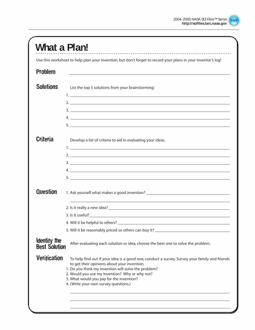
2004–2005 NASA SCI Files™ Serieshttp://scifiles.larc.nasa.gov
103
What a Plan!Use this worksheet to help plan your invention, but don’t forget to record your plans in your inventor’s log!
Problem
Solutions List the top 5 solutions from your brainstorming:
1.
2.
3.
4.
5.
Criteria Develop a list of criteria to aid in evaluating your ideas.
1.
2.
3.
4.
5.
Question 1. Ask yourself what makes a good invention?
2. Is it really a new idea?
3. Is it useful?
4. Will it be helpful to others?
5. Will it be reasonably priced so others can buy it?
Identify the After evaluating each solution or idea, choose the best one to solve the problem.Best Solution
Verification To help find out if your idea is a good one, conduct a survey. Survey your family and friendsto get their opinions about your invention.
1. Do you think my invention will solve the problem?2. Would you use my invention? Why or why not?3. What would you pay for the invention?4. (Write your own survey questions.)
What a Plan!
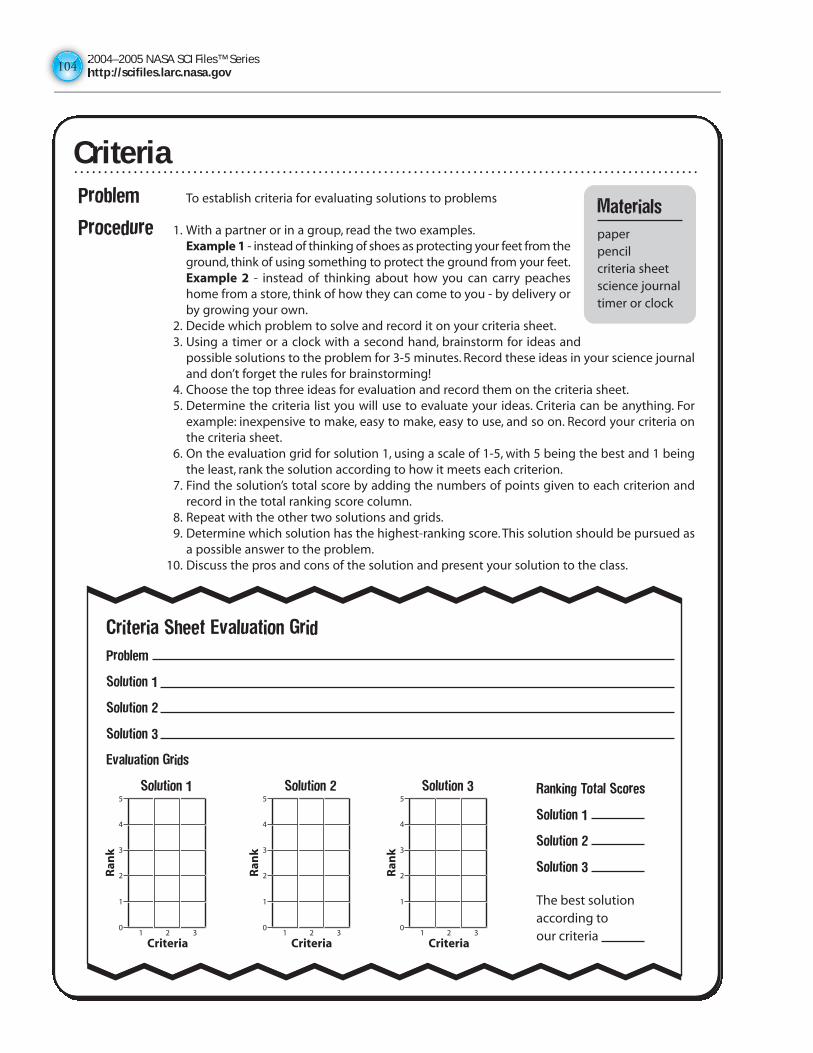
2004–2005 NASA SCI Files™ Serieshttp://scifiles.larc.nasa.gov104104
CriteriaProblem To establish criteria for evaluating solutions to problems
Procedure 1. With a partner or in a group, read the two examples.Example 1 - instead of thinking of shoes as protecting your feet from theground, think of using something to protect the ground from your feet.Example 2 - instead of thinking about how you can carry peacheshome from a store, think of how they can come to you - by delivery orby growing your own.
2. Decide which problem to solve and record it on your criteria sheet.3. Using a timer or a clock with a second hand, brainstorm for ideas and
possible solutions to the problem for 3-5 minutes. Record these ideas in your science journaland don’t forget the rules for brainstorming!
4. Choose the top three ideas for evaluation and record them on the criteria sheet.5. Determine the criteria list you will use to evaluate your ideas. Criteria can be anything. For
example: inexpensive to make, easy to make, easy to use, and so on. Record your criteria onthe criteria sheet.
6. On the evaluation grid for solution 1, using a scale of 1-5, with 5 being the best and 1 beingthe least, rank the solution according to how it meets each criterion.
7. Find the solution’s total score by adding the numbers of points given to each criterion andrecord in the total ranking score column.
8. Repeat with the other two solutions and grids.9. Determine which solution has the highest-ranking score. This solution should be pursued as
a possible answer to the problem.10. Discuss the pros and cons of the solution and present your solution to the class.
Materials
paperpencilcriteria sheetscience journaltimer or clock
10
1
2
3
4
5
2 3
Ran
k
Criteria
Criteria Sheet Evaluation Grid
Problem
Solution 1
Solution 2
Solution 3
Evaluation Grids
Solution 1
10
1
2
3
4
5
2 3
Ran
k
Criteria
Solution 2
10
1
2
3
4
5
2 3
Ran
k
Criteria
Solution 3 Ranking Total Scores
Solution 1
Solution 2
Solution 3
The best solution according toour criteria
Criteria
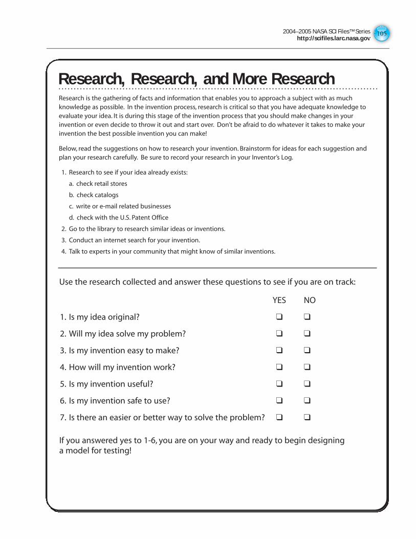
2004–2005 NASA SCI Files™ Serieshttp://scifiles.larc.nasa.gov
105
Research, Research, and More ResearchResearch is the gathering of facts and information that enables you to approach a subject with as muchknowledge as possible. In the invention process, research is critical so that you have adequate knowledge toevaluate your idea. It is during this stage of the invention process that you should make changes in yourinvention or even decide to throw it out and start over. Don’t be afraid to do whatever it takes to make yourinvention the best possible invention you can make!
Below, read the suggestions on how to research your invention. Brainstorm for ideas for each suggestion andplan your research carefully. Be sure to record your research in your Inventor’s Log.
1. Research to see if your idea already exists:
a. check retail stores
b. check catalogs
c. write or e-mail related businesses
d. check with the U.S. Patent Office
2. Go to the library to research similar ideas or inventions.
3. Conduct an internet search for your invention.
4. Talk to experts in your community that might know of similar inventions.
Use the research collected and answer these questions to see if you are on track:
YES NO
1. Is my idea original? ❑ ❑
2. Will my idea solve my problem? ❑ ❑
3. Is my invention easy to make? ❑ ❑
4. How will my invention work? ❑ ❑
5. Is my invention useful? ❑ ❑
6. Is my invention safe to use? ❑ ❑
7. Is there an easier or better way to solve the problem? ❑ ❑
If you answered yes to 1-6, you are on your way and ready to begin designinga model for testing!
Research, Research, and More Research
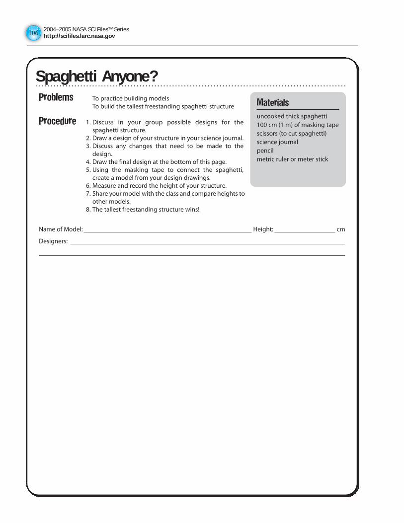
2004–2005 NASA SCI Files™ Serieshttp://scifiles.larc.nasa.gov106106
Spaghetti Anyone?
Problems To practice building modelsTo build the tallest freestanding spaghetti structure
Procedure 1. Discuss in your group possible designs for thespaghetti structure.
2. Draw a design of your structure in your science journal.3. Discuss any changes that need to be made to the
design.4. Draw the final design at the bottom of this page.5. Using the masking tape to connect the spaghetti,
create a model from your design drawings.6. Measure and record the height of your structure.7. Share your model with the class and compare heights to
other models.8. The tallest freestanding structure wins!
Name of Model: Height: cm
Designers:
Materials
uncooked thick spaghetti 100 cm (1 m) of masking tapescissors (to cut spaghetti)science journalpencilmetric ruler or meter stick
Spaghetti Anyone?
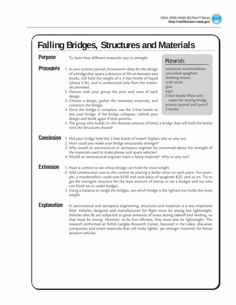
2004–2005 NASA SCI Files™ Serieshttp://scifiles.larc.nasa.gov
107
Purpose To learn how different materials vary in strength.
Procedure 1. In your science journal, brainstorm ideas for the designof a bridge that spans a distance of 30 cm between twobooks, will hold the weight of a 2-liter bottle of liquid(about 5 lb), and is constructed only from the materi-als provided.
2. Discuss with your group the pros and cons of eachdesign.
3. Choose a design, gather the necessary materials, andconstruct the bridge.
4. Once the bridge is complete, use the 2-liter bottle totest your bridge. If the bridge collapses, rethink yourdesign and build again if time permits.
5. The group who builds (in the shortest amount of time) a bridge that will hold the bottlewins the Structures Award!
Conclusion 1. Did your bridge hold the 2-liter bottle of water? Explain why or why not.2. How could you make your bridge structurally stronger?3. Why would an aeronautical or aerospace engineer be concerned about the strength of
the materials used to make planes and space vehicles?4. Would an aeronautical engineer want a heavy material? Why or why not?
Extension 1. Have a contest to see whose bridge can hold the most weight.2. Add construction cost to the contest by placing a dollar value on each piece. For exam-
ple, a marshmallow could cost $100 and each piece of spaghetti $25, and so on. Try toget the strongest structure for the least amount of money or set a budget and see whocan finish on or under budget.
3. Using a balance to weigh the bridges, see which bridge is the lightest but holds the mostweight.
Explanation In aeronautical and aerospace engineering, structures and materials is a very importantfield. Vehicles designed and manufactured for flight must be strong but lightweight.Vehicles that fly are subjected to great amounts of stress during takeoff and landing, sothey must be strong. However, to be fuel efficient, they must also be lightweight. Theresearch performed at NASA Langley Research Center, featured in the video, discussescomposites and smart materials that will make lighter, yet stronger materials for futureaviation vehicles.
Materialsminiature marshmallowsuncooked spaghettidrinking strawscraft sticksgluetape2-liter bottle filled with
water for testing bridgescience journal and pencil2 books
Falling Bridges, Structures and MaterialsFalling Bridges, Structures and Materials
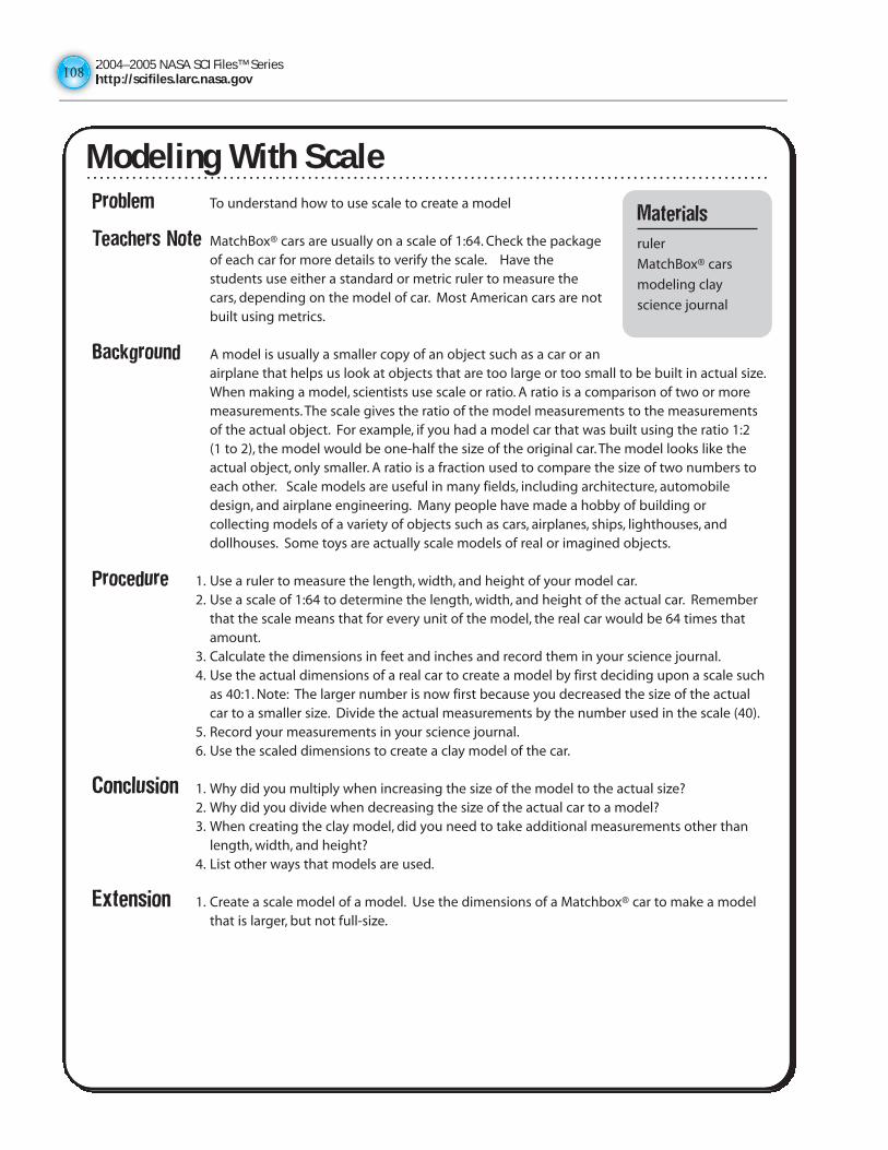
2004–2005 NASA SCI Files™ Serieshttp://scifiles.larc.nasa.gov108108
Problem To understand how to use scale to create a model
Teachers Note MatchBox® cars are usually on a scale of 1:64. Check the packageof each car for more details to verify the scale. Have thestudents use either a standard or metric ruler to measure thecars, depending on the model of car. Most American cars are notbuilt using metrics.
Background A model is usually a smaller copy of an object such as a car or anairplane that helps us look at objects that are too large or too small to be built in actual size.When making a model, scientists use scale or ratio. A ratio is a comparison of two or moremeasurements. The scale gives the ratio of the model measurements to the measurementsof the actual object. For example, if you had a model car that was built using the ratio 1:2 (1 to 2), the model would be one-half the size of the original car. The model looks like theactual object, only smaller. A ratio is a fraction used to compare the size of two numbers toeach other. Scale models are useful in many fields, including architecture, automobiledesign, and airplane engineering. Many people have made a hobby of building orcollecting models of a variety of objects such as cars, airplanes, ships, lighthouses, anddollhouses. Some toys are actually scale models of real or imagined objects.
Procedure 1. Use a ruler to measure the length, width, and height of your model car.2. Use a scale of 1:64 to determine the length, width, and height of the actual car. Remember
that the scale means that for every unit of the model, the real car would be 64 times thatamount.
3. Calculate the dimensions in feet and inches and record them in your science journal.4. Use the actual dimensions of a real car to create a model by first deciding upon a scale such
as 40:1. Note: The larger number is now first because you decreased the size of the actualcar to a smaller size. Divide the actual measurements by the number used in the scale (40).
5. Record your measurements in your science journal.6. Use the scaled dimensions to create a clay model of the car.
Conclusion 1. Why did you multiply when increasing the size of the model to the actual size?2. Why did you divide when decreasing the size of the actual car to a model?3. When creating the clay model, did you need to take additional measurements other than
length, width, and height?4. List other ways that models are used.
Extension 1. Create a scale model of a model. Use the dimensions of a Matchbox® car to make a modelthat is larger, but not full-size.
Modeling With Scale
Materials
ruler
MatchBox® cars
modeling clay
science journal
Modeling With Scale
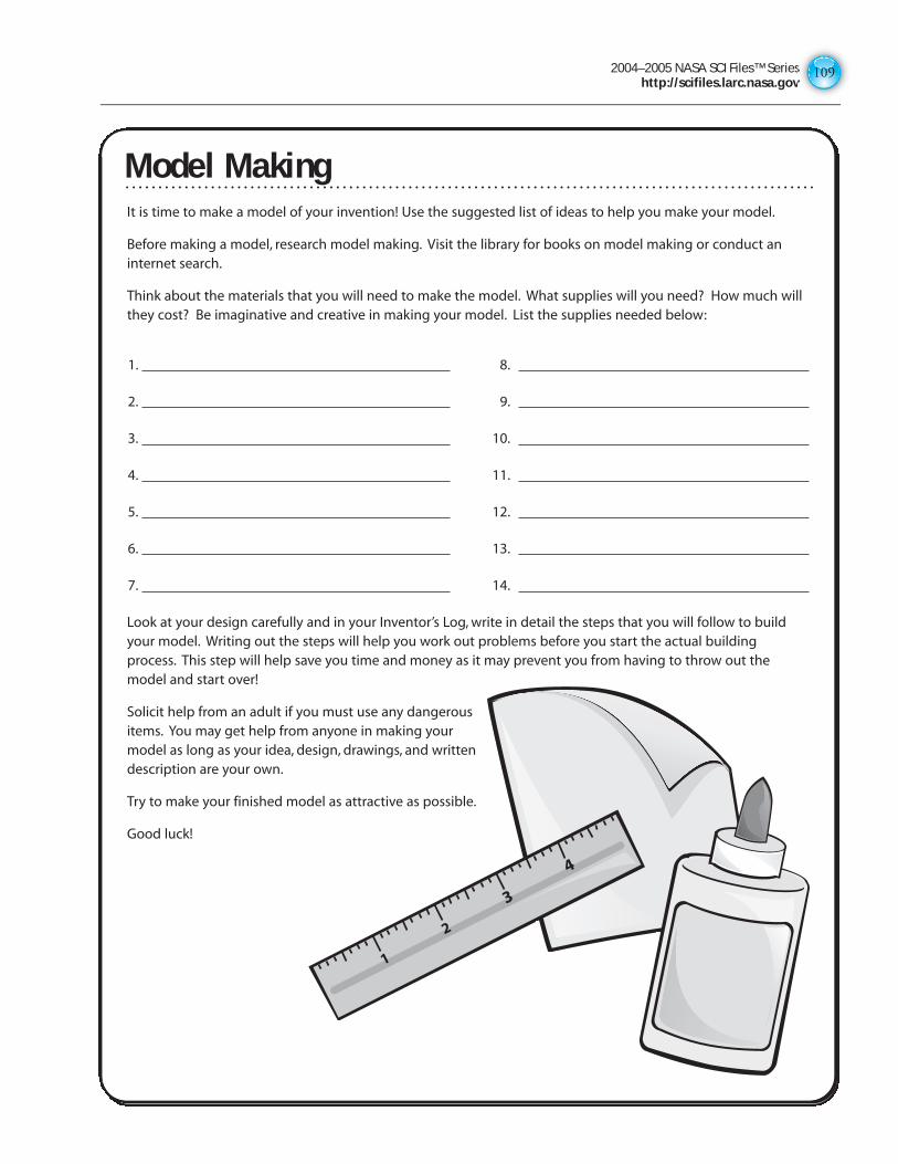
2004–2005 NASA SCI Files™ Serieshttp://scifiles.larc.nasa.gov
109
Model MakingIt is time to make a model of your invention! Use the suggested list of ideas to help you make your model.
Before making a model, research model making. Visit the library for books on model making or conduct aninternet search.
Think about the materials that you will need to make the model. What supplies will you need? How much willthey cost? Be imaginative and creative in making your model. List the supplies needed below:
1. 8.
2. 9.
3. 10.
4. 11.
5. 12.
6. 13.
7. 14.
Look at your design carefully and in your Inventor’s Log, write in detail the steps that you will follow to buildyour model. Writing out the steps will help you work out problems before you start the actual buildingprocess. This step will help save you time and money as it may prevent you from having to throw out themodel and start over!
Solicit help from an adult if you must use any dangerousitems. You may get help from anyone in making yourmodel as long as your idea, design, drawings, and writtendescription are your own.
Try to make your finished model as attractive as possible.
Good luck!
1
2
3
4
Model Making
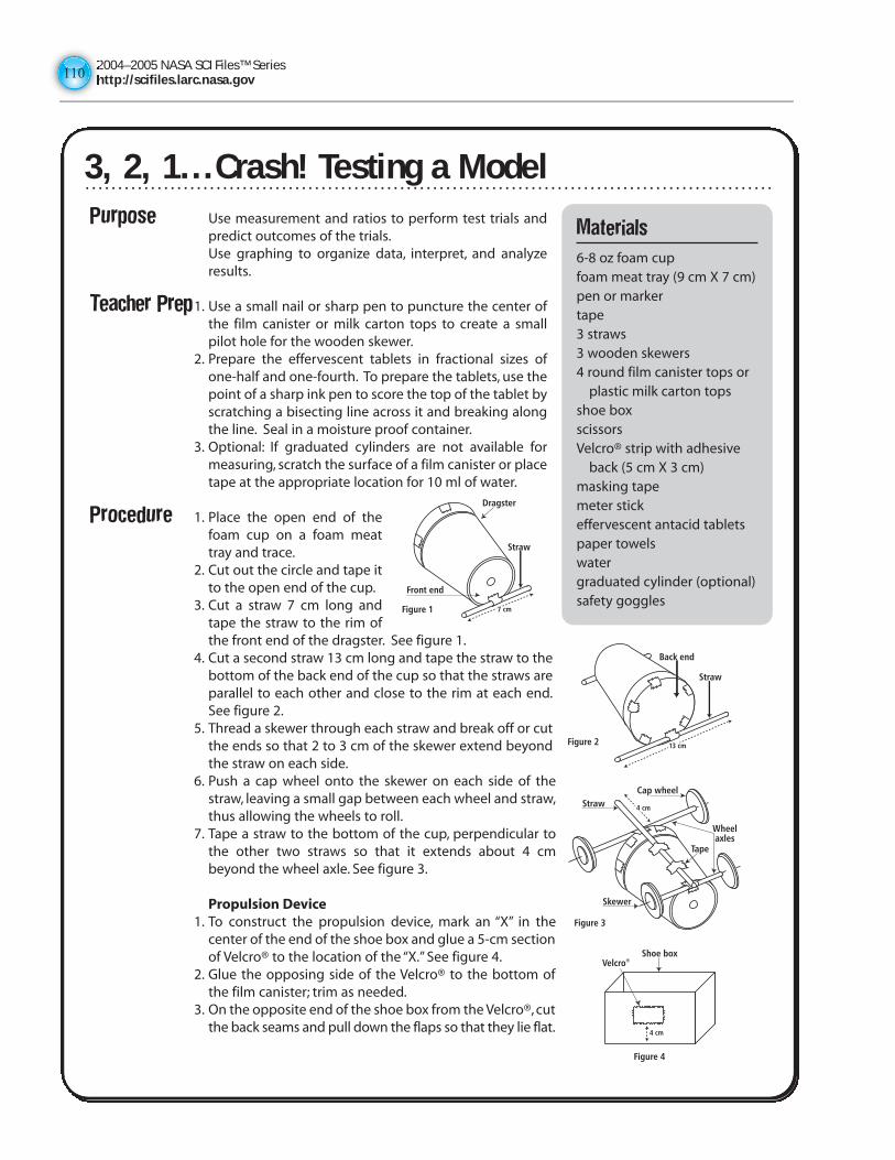
2004–2005 NASA SCI Files™ Serieshttp://scifiles.larc.nasa.gov110110
3, 2, 1… Crash! Testing a ModelPurpose Use measurement and ratios to perform test trials and
predict outcomes of the trials.Use graphing to organize data, interpret, and analyzeresults.
Teacher Prep1. Use a small nail or sharp pen to puncture the center ofthe film canister or milk carton tops to create a smallpilot hole for the wooden skewer.
2. Prepare the effervescent tablets in fractional sizes ofone-half and one-fourth. To prepare the tablets, use thepoint of a sharp ink pen to score the top of the tablet byscratching a bisecting line across it and breaking alongthe line. Seal in a moisture proof container.
3. Optional: If graduated cylinders are not available formeasuring, scratch the surface of a film canister or placetape at the appropriate location for 10 ml of water.
Procedure 1. Place the open end of thefoam cup on a foam meattray and trace.
2. Cut out the circle and tape itto the open end of the cup.
3. Cut a straw 7 cm long andtape the straw to the rim ofthe front end of the dragster. See figure 1.
4. Cut a second straw 13 cm long and tape the straw to thebottom of the back end of the cup so that the straws areparallel to each other and close to the rim at each end.See figure 2.
5. Thread a skewer through each straw and break off or cutthe ends so that 2 to 3 cm of the skewer extend beyondthe straw on each side.
6. Push a cap wheel onto the skewer on each side of thestraw, leaving a small gap between each wheel and straw,thus allowing the wheels to roll.
7. Tape a straw to the bottom of the cup, perpendicular tothe other two straws so that it extends about 4 cmbeyond the wheel axle. See figure 3.
Propulsion Device1. To construct the propulsion device, mark an “X” in the
center of the end of the shoe box and glue a 5-cm sectionof Velcro® to the location of the “X.” See figure 4.
2. Glue the opposing side of the Velcro® to the bottom ofthe film canister; trim as needed.
3. On the opposite end of the shoe box from the Velcro®, cutthe back seams and pull down the flaps so that they lie flat.
Materials
6-8 oz foam cupfoam meat tray (9 cm X 7 cm)pen or markertape3 straws3 wooden skewers4 round film canister tops or
plastic milk carton topsshoe boxscissorsVelcro® strip with adhesive
back (5 cm X 3 cm)masking tapemeter stickeffervescent antacid tabletspaper towelswatergraduated cylinder (optional)safety goggles
7 cmFigure 1
Straw
Dragster
Front end
13 cmFigure 2
Straw
Back end
4 cm
Figure 3
Cap wheelStraw
Skewer
Tape
Wheelaxles
4 cm
Figure 4
Shoe boxVelcro®
3, 2, 1...Crash! Testing a Model
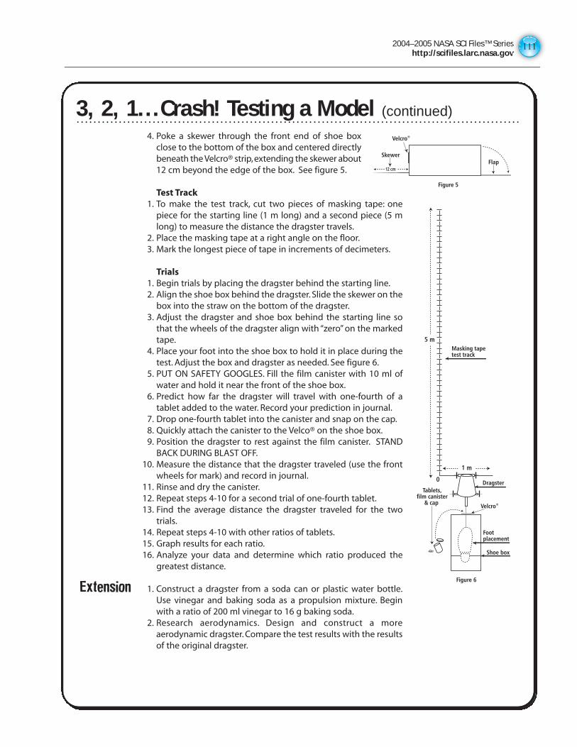
2004–2005 NASA SCI Files™ Serieshttp://scifiles.larc.nasa.gov
111
4. Poke a skewer through the front end of shoe boxclose to the bottom of the box and centered directlybeneath the Velcro® strip,extending the skewer about12 cm beyond the edge of the box. See figure 5.
Test Track1. To make the test track, cut two pieces of masking tape: one
piece for the starting line (1 m long) and a second piece (5 mlong) to measure the distance the dragster travels.
2. Place the masking tape at a right angle on the floor.3. Mark the longest piece of tape in increments of decimeters.
Trials1. Begin trials by placing the dragster behind the starting line.2. Align the shoe box behind the dragster. Slide the skewer on the
box into the straw on the bottom of the dragster.3. Adjust the dragster and shoe box behind the starting line so
that the wheels of the dragster align with “zero” on the markedtape.
4. Place your foot into the shoe box to hold it in place during thetest. Adjust the box and dragster as needed. See figure 6.
5. PUT ON SAFETY GOOGLES. Fill the film canister with 10 ml ofwater and hold it near the front of the shoe box.
6. Predict how far the dragster will travel with one-fourth of atablet added to the water. Record your prediction in journal.
7. Drop one-fourth tablet into the canister and snap on the cap.8. Quickly attach the canister to the Velco® on the shoe box.9. Position the dragster to rest against the film canister. STAND
BACK DURING BLAST OFF.10. Measure the distance that the dragster traveled (use the front
wheels for mark) and record in journal.11. Rinse and dry the canister.12. Repeat steps 4-10 for a second trial of one-fourth tablet.13. Find the average distance the dragster traveled for the two
trials.14. Repeat steps 4-10 with other ratios of tablets.15. Graph results for each ratio.16. Analyze your data and determine which ratio produced the
greatest distance.
Extension 1. Construct a dragster from a soda can or plastic water bottle.Use vinegar and baking soda as a propulsion mixture. Beginwith a ratio of 200 ml vinegar to 16 g baking soda.
2. Research aerodynamics. Design and construct a moreaerodynamic dragster. Compare the test results with the resultsof the original dragster.
3, 2, 1… Crash! Testing a Model (continued)
1 m
5 m
0
Figure 6
Footplacement
Shoe box
Dragster
Masking tapetest track
Tablets,film canister
& cap Velcro®
12 cm
Figure 5
SkewerFlap
Velcro®
3, 2, 1...Crash! Testing a Model (continued)
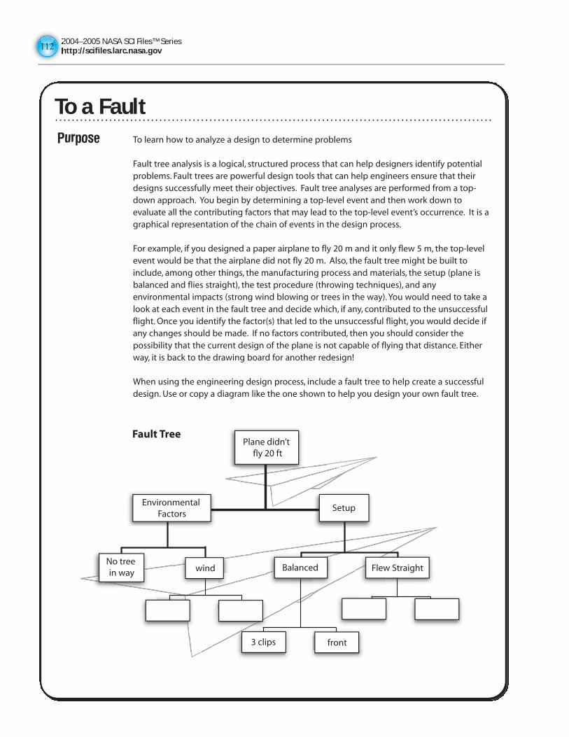
2004–2005 NASA SCI Files™ Serieshttp://scifiles.larc.nasa.gov112112
To a FaultPurpose To learn how to analyze a design to determine problems
Fault tree analysis is a logical, structured process that can help designers identify potentialproblems. Fault trees are powerful design tools that can help engineers ensure that theirdesigns successfully meet their objectives. Fault tree analyses are performed from a top-down approach. You begin by determining a top-level event and then work down toevaluate all the contributing factors that may lead to the top-level event’s occurrence. It is agraphical representation of the chain of events in the design process.
For example, if you designed a paper airplane to fly 20 m and it only flew 5 m, the top-levelevent would be that the airplane did not fly 20 m. Also, the fault tree might be built toinclude, among other things, the manufacturing process and materials, the setup (plane isbalanced and flies straight), the test procedure (throwing techniques), and anyenvironmental impacts (strong wind blowing or trees in the way). You would need to take alook at each event in the fault tree and decide which, if any, contributed to the unsuccessfulflight. Once you identify the factor(s) that led to the unsuccessful flight, you would decide ifany changes should be made. If no factors contributed, then you should consider thepossibility that the current design of the plane is not capable of flying that distance. Eitherway, it is back to the drawing board for another redesign!
When using the engineering design process, include a fault tree to help create a successfuldesign. Use or copy a diagram like the one shown to help you design your own fault tree.
Plane didn’t fly 20 ft
SetupEnvironmental
Factors
No tree in way wind Balanced Flew Straight
3 clips front
Fault Tree
To a Fault
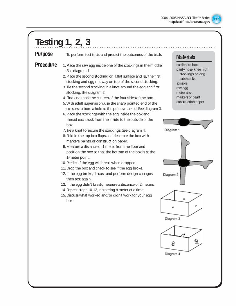
2004–2005 NASA SCI Files™ Serieshttp://scifiles.larc.nasa.gov
113
Purpose To perform test trials and predict the outcomes of the trials
Procedure 1. Place the raw egg inside one of the stockings in the middle.
See diagram 1.
2. Place the second stocking on a flat surface and lay the first
stocking and egg midway on top of the second stocking.
3. Tie the second stocking in a knot around the egg and first
stocking. See diagram 2.
4. Find and mark the centers of the four sides of the box.
5. With adult supervision, use the sharp pointed end of the
scissors to bore a hole at the points marked. See diagram 3.
6. Place the stockings with the egg inside the box and
thread each sock from the inside to the outside of the
box.
7. Tie a knot to secure the stockings. See diagram 4.
8. Fold in the top box flaps and decorate the box with
markers, paints, or construction paper.
9. Measure a distance of 1 meter from the floor and
position the box so that the bottom of the box is at the
1-meter point.
10. Predict if the egg will break when dropped.
11. Drop the box and check to see if the egg broke.
12. If the egg broke, discuss and perform design changes,
then test again.
13. If the egg didn’t break, measure a distance of 2 meters.
14. Repeat steps 10-12, increasing a meter at a time.
15. Discuss what worked and/or didn’t work for your egg
box.
Testing 1, 2, 3Materials
cardboard boxpanty hose, knee high
stockings, or long tube socks
scissorsraw eggmeter stickmarkers or paintconstruction paper
2004–2005 NASA SCI Files™ Serieshttp://scifiles.larc.nasa.gov114114
Extension 1. Design and create an egg drop apparatus of your own and hold an “Operation Egg Drop Contest” at your school by following these guidelines: Invent a package for a raw egg so it can be dropped without breaking from the roof or upper-story window of a tall building. You can package the egg any way you want or attach things to it to slow its descent. However, you can’t simply lower the egg on a string or a long stick--it must free-fall to the ground.
2. To design and build an egg drop apparatus of your own, try using these suggested materials: balloons, strings, marshmallows, bubble wrap, packing peanuts, cloth, and string.
3. Test your design. Use the iterative process of design--analyzing your data from each test and redesigning the box until it works.
Testing 1, 2, 3 (continued)
2004–2005 NASA SCI Files™ Serieshttp://scifiles.larc.nasa.gov
115
The Iterative ProcessThe tree house detectives learned from Mr. Waszak that designing is an iterative process. Iterative means thatfirst you design something, build it, test it, and then you analyze the data from the tests. From the data, thedesign is modified over and over again until it is correct. To begin the iterative process for your invention,carefully design and draw your invention. Remember to draw your invention in detail and label it clearly, neatly,and correctly so that others will understand how the invention works. In your Inventor’s Log, draw a final copyand write a detailed description of your invention.
Draw your invention here:
Description of your invention:
The Iterative Process
2004–2005 NASA SCI Files™ Serieshttp://scifiles.larc.nasa.gov116116
Naming Your InventionYou have an invention and now you need to name it. The name you give your invention is important. Acreative name will show people how creative you are. A name can make people interested in your invention bycatching their eye. The right name will even help people remember your invention for all time! Give it a lot ofthought; however, an invention’s name can be changed at any time.
There are many ways to name an invention. Below are some ideas to help you think about naming yourinvention. Read the examples and then put some thought into creating a name for your invention using eachidea. After completing all the suggestions, choose the one you like best.
An invention is often named for what it is made of, for example: ice cream, popcorn, corn meal, rubber cement,shredded wheat, and down coat.
Possible name for your invention:
Inventions are sometimes named after the inventor, for example: Singer Sewing Machine, Morse Code, WrightFlyer, John Deere Tractor, Ford Truck, Heinz Ketchup, and Ferris Wheel.
Possible name for your invention:
Some inventions are named for their function (the way they work), for example: hair dryer, toothbrush,sunglasses, roller blades, hairbrush, screwdriver, space shuttle, and frying pan.
Possible name for your invention:
A funny or clever name will often make people remember an invention, for example: Silly Putty, Flip Flops,Beanie Babies, and Cool Whip.
Possible name for your invention:
Descriptive, rhyming names and abbreviations are also unique ways to name your invention, for example: VCR,TV, CD player, Rosy Posy, Curious George, and GI Joe.
Possible name for your invention:
My invention’s name is :
Naming Your Invention
2004–2005 NASA SCI Files™ Serieshttp://scifiles.larc.nasa.gov
117
TrademarksPurpose To have a basic understanding of trademarks
Background A trademark can be a letter, number, word, phrase, sound, smell,shape, color, logo, picture, aspect of packaging, or any combinationof these that is used to distinguish goods and services of onetrader from those of another. A small “TM” designates a trademark.When an inventor applies for a trademark, the TM designation isused as a superscript to the product name. Once the trademark hasbeen registered, the superscript ® appears at the end of theproduct name. Example: Velcro™, Velcro ® http://www.uspto.gov
Procedure 1. Find pictures of trademarks in the magazines and cut them out.2. Position the trademarks onto a piece of construction paper and glue them on.3. Use markers or crayons to fill in the gaps, repeat the logos, and so on.4. In your own words on the back of your collage, define trademark.5. Share your collage with your class.
Extensions 1. Design an original trademark for your invention or other product.2. Use a computer program to design an original trademark.3. Use your name and create an original trademark.4. Look at various company logos such as Disney, Barbie, Nintendo, Lego, Pokemon, Apple
Computers, and Visa. Create a company logo for an imaginary company you would like toown someday.
Materials
magazinesgluescissorsconstruction papermarkers or crayons
Trademarks
2004–2005 NASA SCI Files™ Serieshttp://scifiles.larc.nasa.gov118118
Copy Cat or Copyright?Purpose To explain copyright and recognize a copyright symbol
Background Copyright protects the original expression of ideas, not the ideasthemselves. It automatically safeguards your original works of art,literature, music, films, broadcasts, and computer programs fromcopying and certain other uses.
The copyright protects the form of expression rather than thesubject matter of the writing. For example, a description of amachine could be copyrighted but would only prevent othersfrom copying the description; it would not prevent others from writing a description of theirown or from making and using the machine. Copyrights are registered by the CopyrightOffice of the Library of Congress. http://lcweb.loc.gov/copyright/
Procedure 1. Using the Internet or books, research the background of Haiku poetry.http://www.hsa-haiku.orghttp://www.haiku.cchttp://www.tecnet.or.jp/~haiku
2. Take turns in your group reading samples of Haiku poetry.3. How many syllables are in the first line? Second line? Third line?4. Discuss Haiku poetry and its purpose.5. Write a Haiku poem and share it with your group for editing.6. If necessary, revise your poem.7. Discuss how to protect your original poem from someone copying your work.8. Look in various books, newspapers, and magazines to find copyright information. What is the
symbol that lets the reader know the material is copyrighted?9. Copy your poem onto art paper and illustrate.
10. Place the copyright symbol (©), along with the year and your name, on your original work ofpoetry and art.
Materials
Haiku poetry samplespencilpaperart papermarkers or crayons
Copy Cat or Copyright?
2004–2005 NASA SCI Files™ Serieshttp://scifiles.larc.nasa.gov
119
Procedure Using books, encyclopedias, and the Internet, research the following terms. Define and give examples of each.
intellectual property:
patent:
copyright:
trademark:
trade secret:
Extension 1. Write the patent office to get information on how to file a patent. 2. Locate objects at home or school that have trademarks. Draw the trademark symbol. 3. Create your own trademark by making an original drawing or logo that represents you. 4. Locate patent numbers or “patent pending” on objects. Why are patents numbered? What
does “patent pending” mean? 5. Look in books and periodicals for copyright information. What is protected by a copyright? 6. Learn more about copyright and how to register a copyright at http://www.loc.gov/
copyright/circs/circ1.html#cr 7. Create your own “trade secret.” Discuss things that might be trade secrets in real life.
Invention Protection
2004–2005 NASA SCI Files™ Serieshttp://scifiles.larc.nasa.gov120120
Purpose To research various careers in mathematics, science, and technology
Procedure 1. Review the “Career Search Questions” listed below. 2. Brainstorm a list of careers that would use mathematics,
science, and technology. 3. Decide with your partner which career you would like to
research. 4. You can either begin your research by visiting the following web sites or by conducting a
general search using a search engine. A general search will help you find more information on your specific career.
http://kids.msfc.nasa.gov/Rockets/Careers.asp http://mgs-mager.gsfc.nasa.gov/Kids/careers.html http://stats.bls.gov/k12/html/edu_over.htm http://swe.org 5. During your research, answer as many of the Career Research Questions as possible and
record the answers in your science journal. 6. Share your career information with the class.
Conclusion Career Research Questions 1. What type of work do people in this career perform?
2. Is there a demand for this job in the future?
3. What kind of education is needed for this type of work?
4. What is the current salary of this occupation?
5. What are some other jobs that are similar to this one?
Extension 1. Hold a career day in your class or school. 2. Contact various people who use mathematics, science, and technology in their jobs and ask
them to discuss their careers. 3. Have the students dress in character and give a report about their chosen career field.
So What Do You Want to Do When You Grow Up?
Materials
internet accesscareer research
questions
2004–2005 NASA SCI Files™ Serieshttp://scifiles.larc.nasa.gov
121
ANSWER KEY
Mousetrap Car
Answers will vary.
Bugging out the Bugs
Answers will vary.
Brain Brewing Storms
Answers will vary.
What a Plan!
Answers will vary.
Research, Research, and More Research
Answers will vary.
Falling Bridges
1. Answers will vary.
2. Answers will vary.
3. An aeronautical or aerospace engineer wants to make materials strong so they can endure the stress of flight. They would want to make the materials lightweight so that they will save on fuel consumption.
4. An aeronautical engineer would not want a heavy material because it would take too much fuel to lift off and fly the plane.
Modeling With Scale
1. You had to multiply because the scale model is smaller than the actual size. Therefore, you had to increase the measurement of the model by the scale. To do that you have to multiply.
2. When you are decreasing from actual size to a model, you have to divide the measurements by the scale to get the size of the model.
3. Answers will vary, but depending on the type of model being created, it may have been necessary to take additional measurements to accurately make the model.
4. Answers will vary but might include toys, designing houses, showcase of new playground, dollhouse, model home, and so on.
So What Do You Want to Do When You Grow Up?
1-5. Answers will vary.