Embed Size (px)
Citation preview
NASA SPECIAL SESSION: NEXT-GENERATION
RADIOISOTOPE THERMOELECTRIC GENERATOR (RTG) DISCUSSION
June F. Zakrajsek, NASA
Dave F. Woerner, JPL/Cal Tech
Jean-Pierre Fleurial, JPL/Cal Tech
www.nasa.gov
Purpose of this Session
• Provide Background on the Next Generation RTG Study results
• Discuss current NASA investments in TE technologies
• Initiate discussion with TE and RPS community on potential plans for technology maturation of a Next Generation RTG
• Discuss upcoming RFI and potential RFP
Pre-Decisional for Discussion Only 2
Agenda
• Background
• Next-Generation RTG Study
• TE Materials and Technology
• NASA conceptual plan forward
• Q&A
3 Pre-Decisional for Discussion Only
BACKGROUND
RADIOISOTOPE POWER SYSTEMS PROGRAM
4 Pre-Decisional for Discussion Only
5 Pre-Decisional for Discussion Only
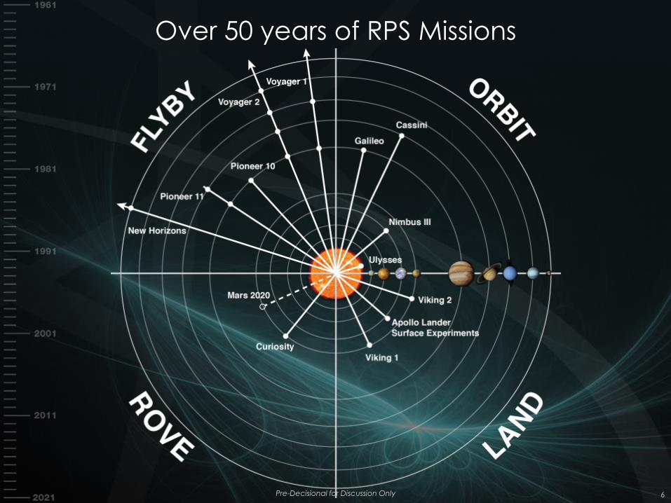
Over 50 years of RPS Missions
Pre-Decisional for Discussion Only 6
RPS Objective and Level I Requirements
• Program Objective
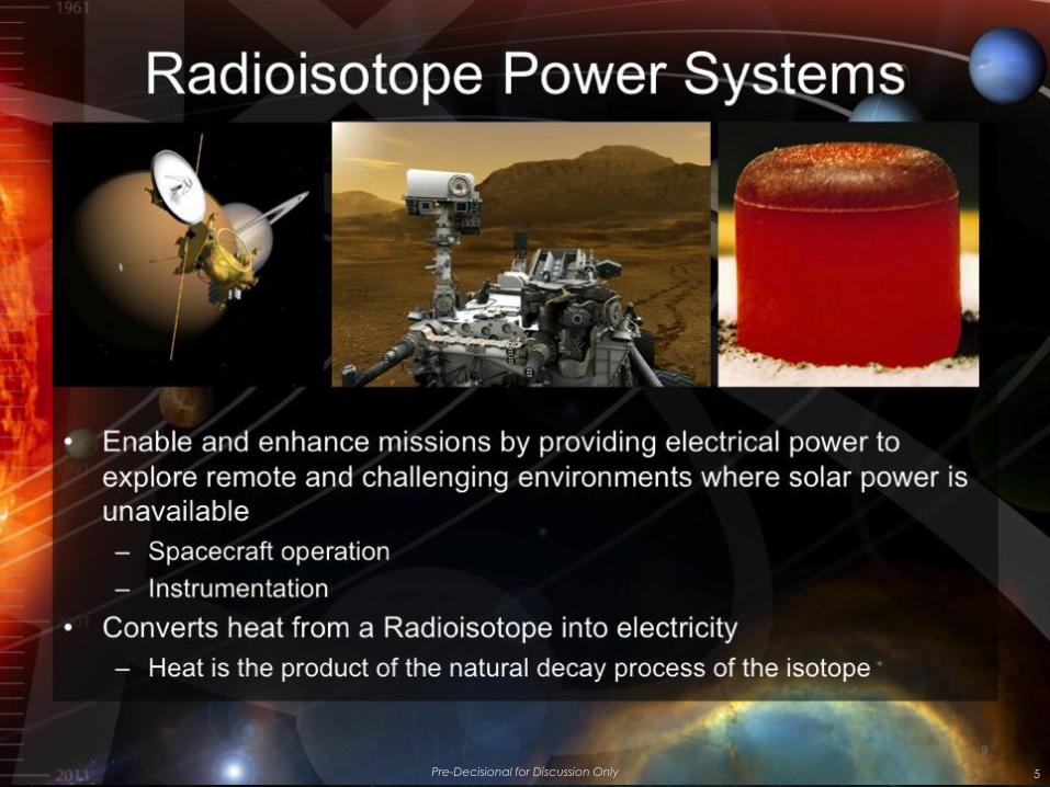
– Ensure the availability of RPS for the exploration of the solar
system in environments where conventional solar or chemical
power generation is impractical or impossible.
• Program Level I Requirements
– PCA-1: The RPS Program shall procure RPS for SMD missions.
– PCA-2: The RPS Program shall sustain the capability to conduct RPS missions.
– PCA-3: The RPS Program shall develop RPS technologies for
insertion into flight systems.
– PCA-4: The RPS Program shall manage the nuclear launch
safety approval process for RPS.
7 Pre-Decisional for Discussion Only
Flight Systems for Current Missions
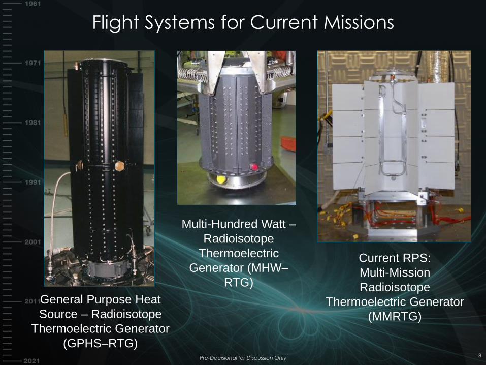
General Purpose Heat
Source – Radioisotope
Thermoelectric Generator
(GPHS–RTG)
Current RPS:
Multi-Mission
Radioisotope
Thermoelectric Generator
(MMRTG)
8
Multi-Hundred Watt –
Radioisotope
Thermoelectric
Generator (MHW–
RTG)
Pre-Decisional for Discussion Only
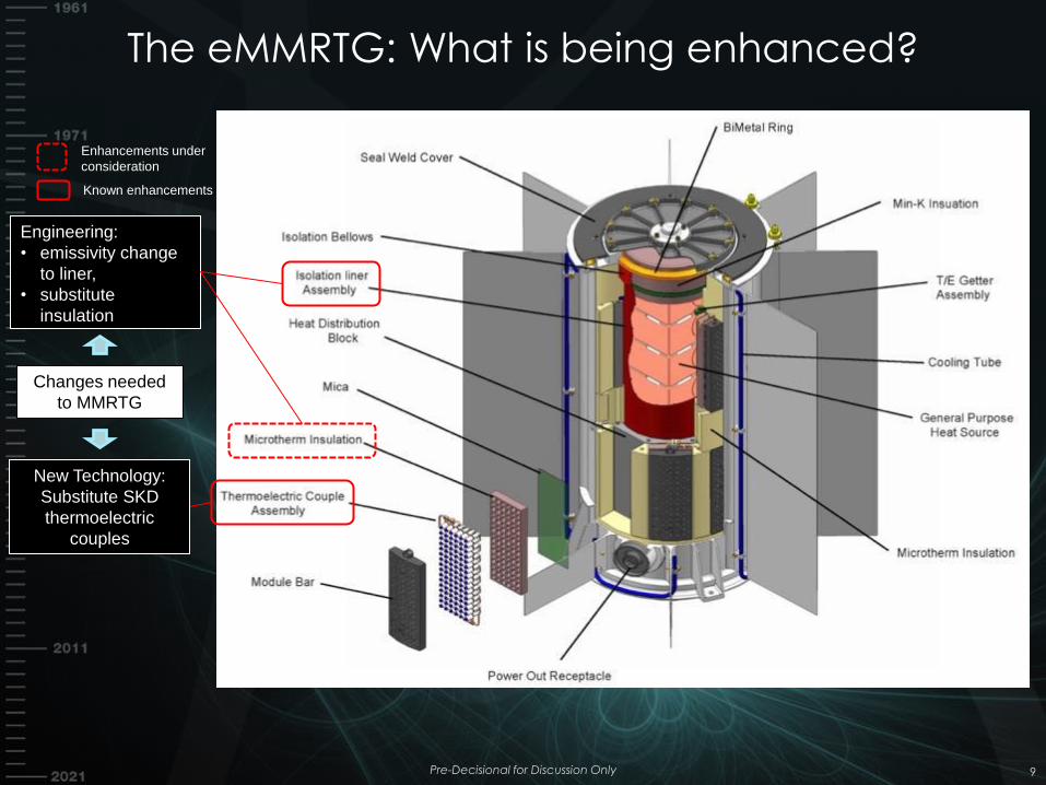
Engineering:
• emissivity change
to liner,
• substitute
insulation
Known enhancements
Enhancements under
consideration
Changes needed
to MMRTG
New Technology:
Substitute SKD
thermoelectric
couples
The eMMRTG: What is being enhanced?
Pre-Decisional for Discussion Only 9
Next-Generation RTG Study Objectives
Determine the characteristics of a Next-Generation RTG that
would “best” fulfill Planetary Science Division (PSD) mission
needs. This study is limited to systems that convert heat to
electricity using thermocouples. “Best” is defined as a confluence
of the following factors:
• An RTG that would be useful across the solar system
• An RTG that maximizes the types of potential missions: flyby,
orbiter, lander, rover, boats, submersibles, balloons
• An RTG that has reasonable development risks and timeline
• An RTG that has a value (importance, worth and usefulness)
returned to PSD that warrants the investment as compared
with retaining existing baseline systems
Pre-Decisional for Discussion Only 10
NEXT-GENERATION RTG STUDY
RADIOISOTOPE POWER SYSTEMS PROGRAM
11 Pre-Decisional for Discussion Only
Next-Generation RTGs for NASA – Topics
• Approach
• Mission Analysis Overview
• Radioisotope Thermoelectric Generators (RTGs)
• RTG Design Trades and Risks
• Next-Generation RTG Concepts
• Summary of findings
Pre-Decisional for Discussion Only 12
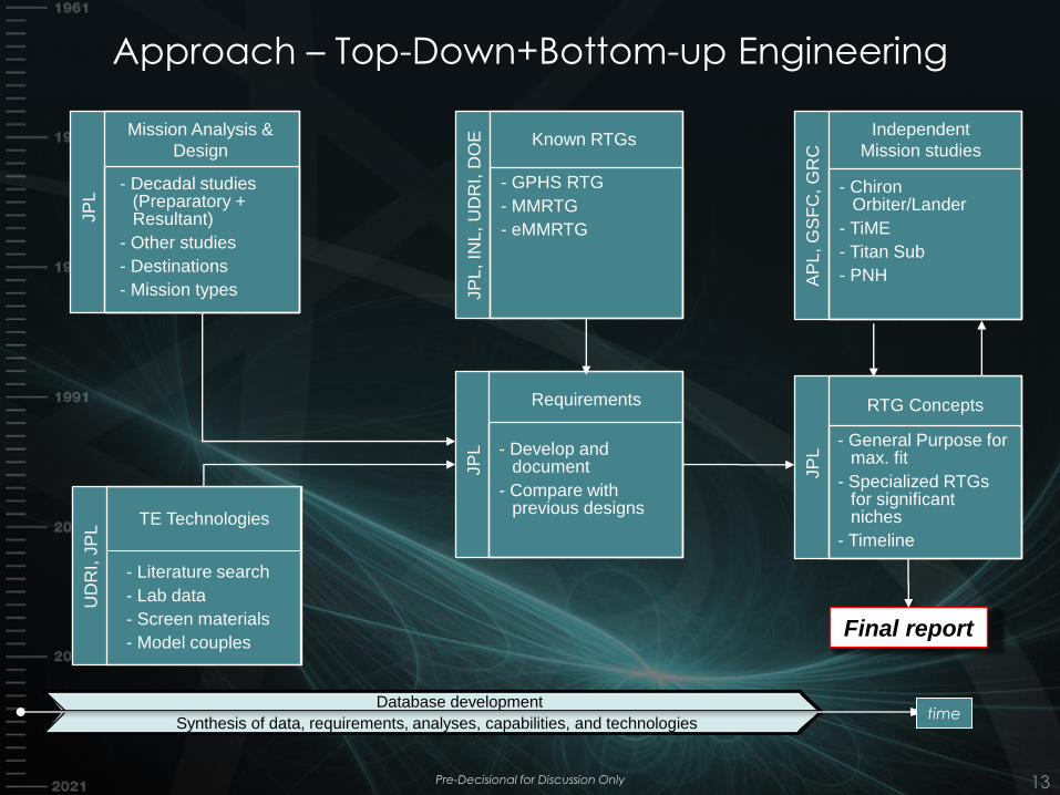
Approach – Top-Down+Bottom-up Engineering
Pre-Decisional for Discussion Only 13
Mission Analysis &
Design
- Decadal studies (Preparatory + Resultant)
- Other studies
- Destinations
- Mission types
JP
L
TE Technologies
- Literature search
- Lab data
- Screen materials
- Model couples
UD
RI,
JP
L
Requirements
- Develop and document
- Compare with previous designs
JP
L
Known RTGs
- GPHS RTG
- MMRTG
- eMMRTG
JP
L, IN
L,
UD
RI, D
OE
Independent
Mission studies
- Chiron Orbiter/Lander
- TiME
- Titan Sub
- PNH AP
L, G
SF
C, G
RC
RTG Concepts
- General Purpose for max. fit
- Specialized RTGs for significant niches
- Timeline
JP
L
Database development
Synthesis of data, requirements, analyses, capabilities, and technologies
Final report
time
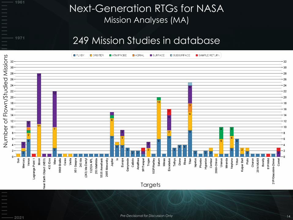
Next-Generation RTGs for NASA Mission Analyses (MA)
249 Mission Studies in database
Pre-Decisional for Discussion Only 14
Nu
mb
er
of
Flo
wn
/Stu
die
d M
issi
on
s
Targets
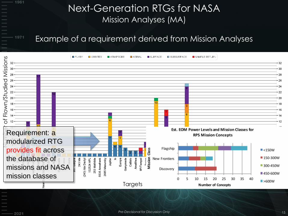
Next-Generation RTGs for NASA Mission Analyses (MA)
Example of a requirement derived from Mission Analyses
15
Nu
mb
er
of
Flo
wn
/Stu
die
d M
issi
on
s
Targets
Requirement: a
modularized RTG
provides fit across
the database of
missions and NASA
mission classes
Pre-Decisional for Discussion Only
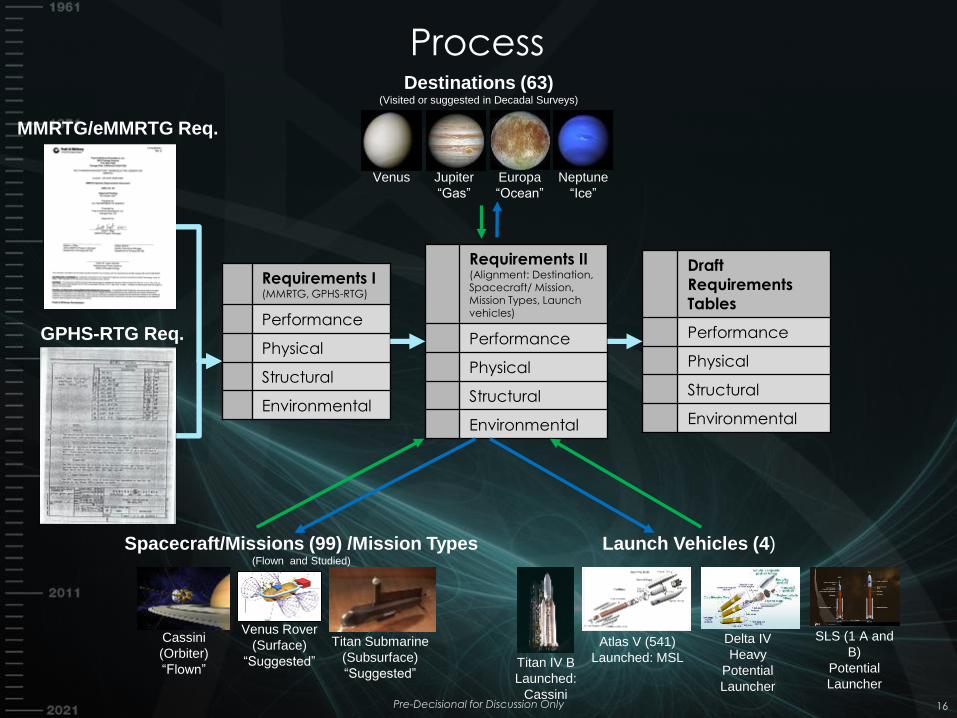
Requirements I (MMRTG, GPHS-RTG)
Performance
Physical
Structural
Environmental
Requirements II (Alignment: Destination, Spacecraft/ Mission, Mission Types, Launch vehicles)
Performance
Physical
Structural
Environmental
MMRTG/eMMRTG Req.
GPHS-RTG Req.
Destinations (63) (Visited or suggested in Decadal Surveys)
Venus Jupiter
“Gas”
Europa
“Ocean”
Neptune
“Ice”
Spacecraft/Missions (99) /Mission Types (Flown and Studied)
Cassini
(Orbiter)
“Flown”
Venus Rover
(Surface)
“Suggested”
Titan Submarine
(Subsurface)
“Suggested”
Launch Vehicles (4)
Atlas V (541)
Launched: MSL
Delta IV
Heavy
Potential
Launcher
SLS (1 A and
B)
Potential
Launcher
Titan IV B
Launched:
Cassini
Draft
Requirements
Tables
Performance
Physical
Structural
Environmental
Process
Pre-Decisional for Discussion Only 16
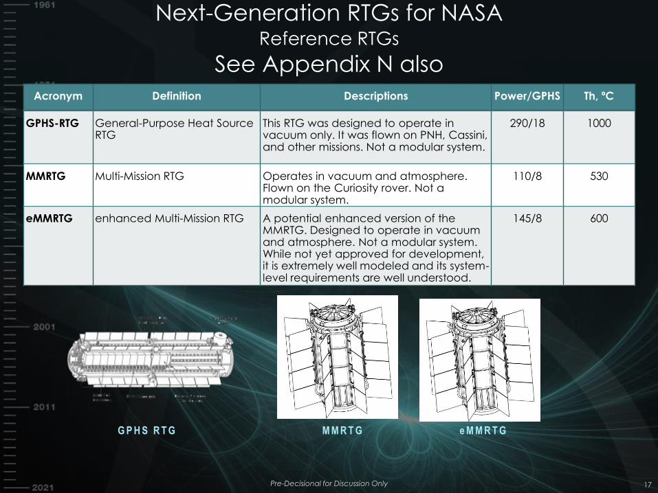
Next-Generation RTGs for NASA Reference RTGs
See Appendix N also
Pre-Decisional for Discussion Only 17
Acronym Definition Descriptions Power/GPHS Th, ºC
GPHS-RTG General-Purpose Heat Source RTG
This RTG was designed to operate in vacuum only. It was flown on PNH, Cassini, and other missions. Not a modular system.
290/18 1000
MMRTG Multi-Mission RTG Operates in vacuum and atmosphere. Flown on the Curiosity rover. Not a modular system.
110/8 530
eMMRTG enhanced Multi-Mission RTG A potential enhanced version of the MMRTG. Designed to operate in vacuum and atmosphere. Not a modular system. While not yet approved for development, it is extremely well modeled and its system-level requirements are well understood.
145/8 600
G P H S R T G M M R T G e M M R T G
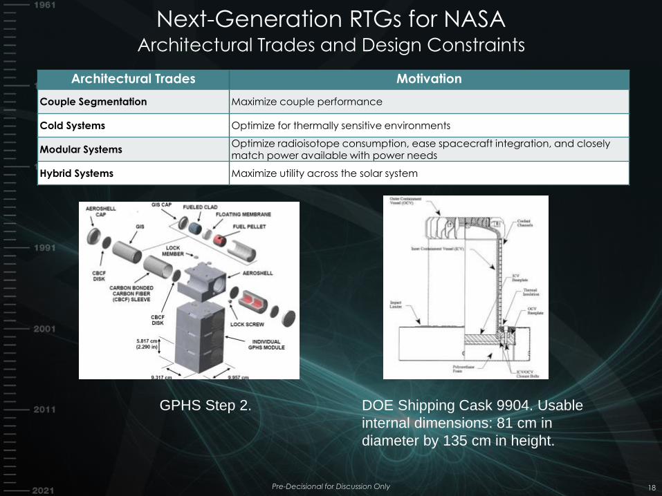
Next-Generation RTGs for NASA Architectural Trades and Design Constraints
Pre-Decisional for Discussion Only 18
Architectural Trades Motivation
Couple Segmentation Maximize couple performance
Cold Systems Optimize for thermally sensitive environments
Modular Systems Optimize radioisotope consumption, ease spacecraft integration, and closely match power available with power needs
Hybrid Systems Maximize utility across the solar system
DOE Shipping Cask 9904. Usable
internal dimensions: 81 cm in
diameter by 135 cm in height.
GPHS Step 2.
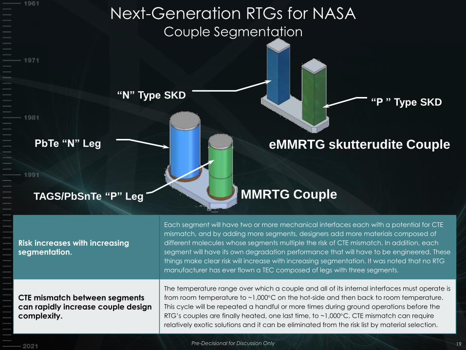
Next-Generation RTGs for NASA Couple Segmentation
Pre-Decisional for Discussion Only 19
Risk increases with increasing segmentation.
Each segment will have two or more mechanical interfaces each with a potential for CTE
mismatch, and by adding more segments, designers add more materials composed of
different molecules whose segments multiple the risk of CTE mismatch. In addition, each
segment will have its own degradation performance that will have to be engineered. These
things make clear risk will increase with increasing segmentation. It was noted that no RTG
manufacturer has ever flown a TEC composed of legs with three segments.
CTE mismatch between segments can rapidly increase couple design complexity.
The temperature range over which a couple and all of its internal interfaces must operate is
from room temperature to ~1,000C on the hot-side and then back to room temperature.
This cycle will be repeated a handful or more times during ground operations before the
RTG’s couples are finally heated, one last time, to ~1,000C. CTE mismatch can require
relatively exotic solutions and it can be eliminated from the risk list by material selection.
“P ” Type SKD
TAGS/PbSnTe “P” Leg
PbTe “N” Leg
MMRTG Couple
eMMRTG skutterudite Couple
“N” Type SKD
Next-Generation RTGs for NASA “Cold” RTGs
• Cold RTGs were devised to minimize housing
temperature to ease spacecraft integration and
maximize power
• Three options were available: use triple-segmented
couples operating near 1000 ºC, use double-
segmented couples near 600 ºC, or use couples
spanning a smaller temperature range such as 800
ºC to 50 ºC.
Pre-Decisional for Discussion Only 20
Risk increases with increasing
segmentation.
Each segment will have two or more mechanical interfaces each with a
potential for CTE mismatch, and by adding more segments, designers add more
materials composed of different molecules whose segments multiple the risk of
CTE mismatch. In addition, each segment will have its own degradation
performance that will have to be engineered. These things make clear risk will
increase with increasing segmentation. It was noted that no RTG manufacturer
has ever flown a TEC composed of legs with three segments.
CTE mismatch between segments can
rapidly increase couple design
complexity.
The temperature range over which a couple and all of its internal interfaces
must operate is from room temperature to ~1,000C on the hot-side and then
back to room temperature. This cycle will be repeated a handful or more times
during ground operations before the RTG’s couples are finally heated, one last
time, to ~1,000C. CTE mismatch can require relatively exotic solutions and it can
be eliminated from the risk list by material selection.
Next-Generation RTGs for NASA Modularization
Pre-Decisional for Discussion Only 21
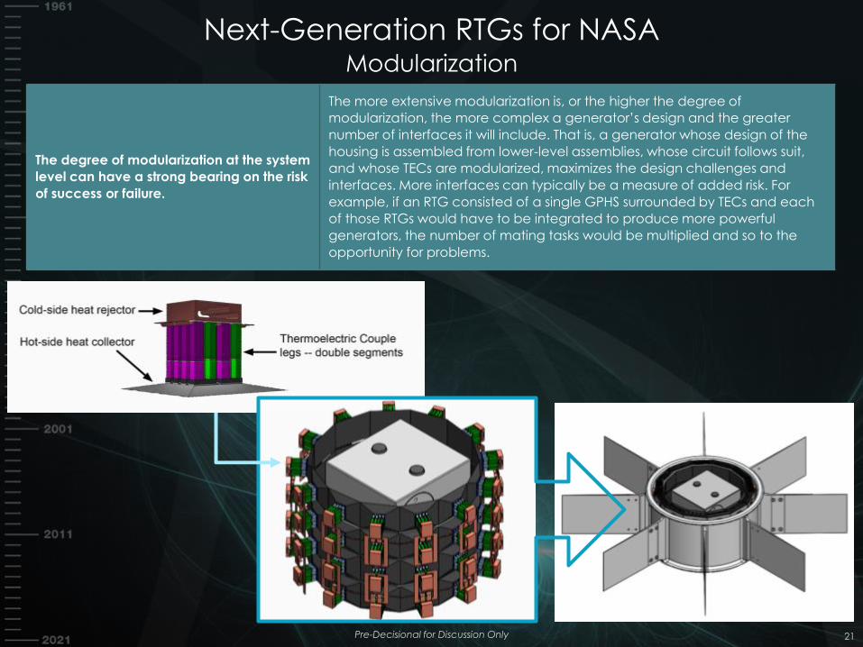
The degree of modularization at the system
level can have a strong bearing on the risk
of success or failure.
The more extensive modularization is, or the higher the degree of
modularization, the more complex a generator’s design and the greater
number of interfaces it will include. That is, a generator whose design of the
housing is assembled from lower-level assemblies, whose circuit follows suit,
and whose TECs are modularized, maximizes the design challenges and
interfaces. More interfaces can typically be a measure of added risk. For
example, if an RTG consisted of a single GPHS surrounded by TECs and each
of those RTGs would have to be integrated to produce more powerful
generators, the number of mating tasks would be multiplied and so to the
opportunity for problems.
Next-Generation RTGs for NASA Hybridization
Pre-Decisional for Discussion Only 22
Hybridization incurs risk by being responsive to too many functional requirements, that is, it risks failure while trying to satisfy all users.
Too many requirements can increase engineering focus on development of system-level solutions. This compounds the risk to an RTG system by increasing design and manufacturing challenges while potentially increasing risk in thermoelectric couple technologies for this variety of Next-Generation RTG concepts. As examples,
• Guaranteeing hermeticity for the life of an RTG is a challenge.
• Many of the components in an MMRTG-like design, a known design that works, must be discarded to provide a lightweight system requiring designers to create new system-level solutions. No such RTG exists for spaceflight.
Next-Generation RTGs for NASA Types and Features
Pre-Decisional for Discussion Only 23
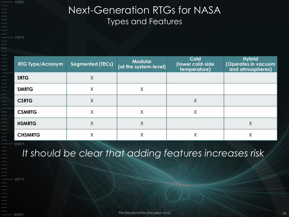
RTG Type/Acronym Segmented (TECs) Modular
(at the system-level)
Cold (lower cold-side
temperature)
Hybrid (Operates in vacuum
and atmospheres)
SRTG X
SMRTG X X
CSRTG X X
CSMRTG X X X
HSMRTG X X X
CHSMRTG X X X X
It should be clear that adding features increases risk
Next-Generation RTGs for NASA What is in a name?
24
Prefix Definition Description
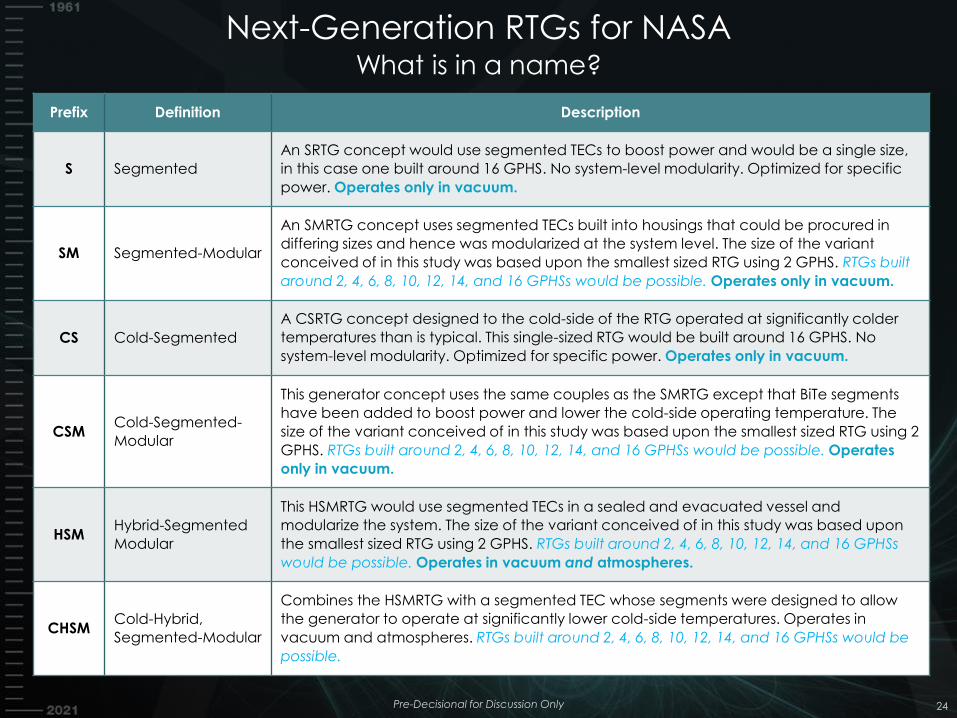
S Segmented
An SRTG concept would use segmented TECs to boost power and would be a single size,
in this case one built around 16 GPHS. No system-level modularity. Optimized for specific
power. Operates only in vacuum.
SM Segmented-Modular
An SMRTG concept uses segmented TECs built into housings that could be procured in
differing sizes and hence was modularized at the system level. The size of the variant
conceived of in this study was based upon the smallest sized RTG using 2 GPHS. RTGs built
around 2, 4, 6, 8, 10, 12, 14, and 16 GPHSs would be possible. Operates only in vacuum.
CS Cold-Segmented
A CSRTG concept designed to the cold-side of the RTG operated at significantly colder
temperatures than is typical. This single-sized RTG would be built around 16 GPHS. No
system-level modularity. Optimized for specific power. Operates only in vacuum.
CSM Cold-Segmented-
Modular
This generator concept uses the same couples as the SMRTG except that BiTe segments
have been added to boost power and lower the cold-side operating temperature. The
size of the variant conceived of in this study was based upon the smallest sized RTG using 2
GPHS. RTGs built around 2, 4, 6, 8, 10, 12, 14, and 16 GPHSs would be possible. Operates
only in vacuum.
HSM Hybrid-Segmented
Modular
This HSMRTG would use segmented TECs in a sealed and evacuated vessel and
modularize the system. The size of the variant conceived of in this study was based upon
the smallest sized RTG using 2 GPHS. RTGs built around 2, 4, 6, 8, 10, 12, 14, and 16 GPHSs
would be possible. Operates in vacuum and atmospheres.
CHSM Cold-Hybrid,
Segmented-Modular
Combines the HSMRTG with a segmented TEC whose segments were designed to allow
the generator to operate at significantly lower cold-side temperatures. Operates in
vacuum and atmospheres. RTGs built around 2, 4, 6, 8, 10, 12, 14, and 16 GPHSs would be
possible.
Pre-Decisional for Discussion Only
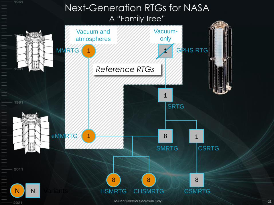
Next-Generation RTGs for NASA A “Family Tree”
Pre-Decisional for Discussion Only 25
MMRTG
eMMRTG
GPHS RTG
SRTG
CSRTG SMRTG
CSMRTG CHSMRTG HSMRTG
1
1
1
1
1 8
8 8 8
N Variants
Reference RTGs
N
Vacuum and
atmospheres
Vacuum-
only
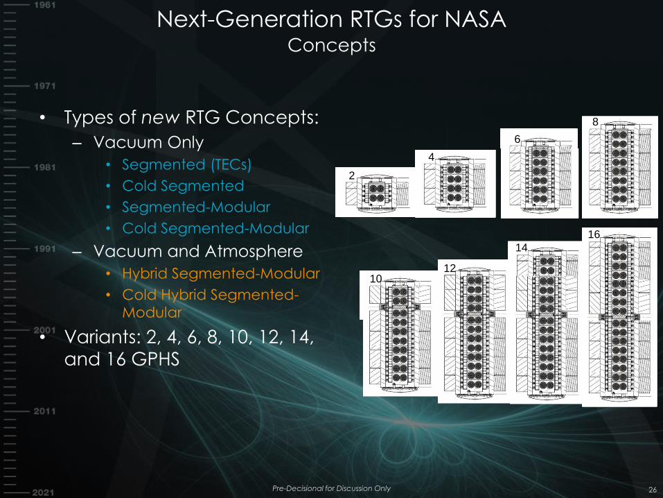
Next-Generation RTGs for NASA Concepts
Pre-Decisional for Discussion Only 26
• Types of new RTG Concepts:
– Vacuum Only
• Segmented (TECs)
• Cold Segmented
• Segmented-Modular
• Cold Segmented-Modular
– Vacuum and Atmosphere
• Hybrid Segmented-Modular
• Cold Hybrid Segmented-
Modular
• Variants: 2, 4, 6, 8, 10, 12, 14,
and 16 GPHS
2
4
8
10 12
16
14
6
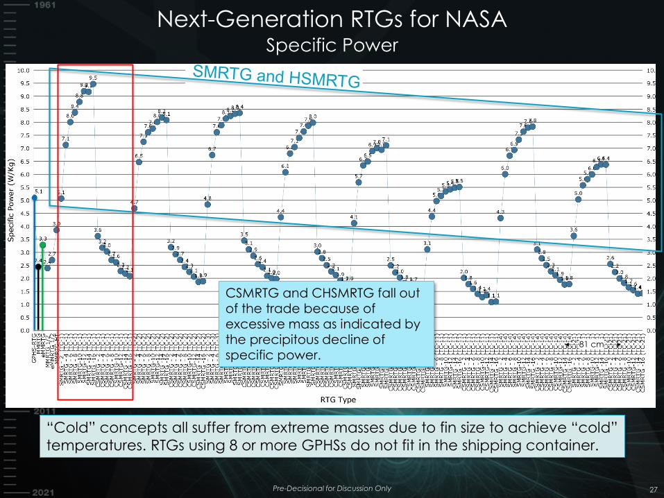
Next-Generation RTGs for NASA Specific Power
Pre-Decisional for Discussion Only 27
81 cm
“Cold” concepts all suffer from extreme masses due to fin size to achieve “cold”
temperatures. RTGs using 8 or more GPHSs do not fit in the shipping container.
CSMRTG and CHSMRTG fall out of the trade because of excessive mass as indicated by the precipitous decline of specific power.
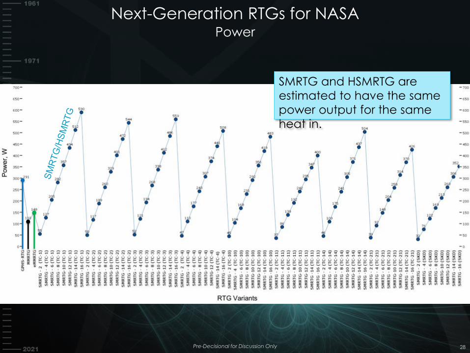
Next-Generation RTGs for NASA Power
Pre-Decisional for Discussion Only 28
SMRTG and HSMRTG are
estimated to have the same
power output for the same
heat in.
Next-Generation RTGs for NASA Concepts
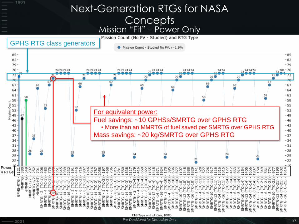
Pre-Decisional for Discussion Only 29
29
GPHS RTG class generators
Power,
4 RTGs
For equivalent power:
Fuel savings: ~10 GPHSs/SMRTG over GPHS RTG • More than an MMRTG of fuel saved per SMRTG over GPHS RTG
Mass savings: ~20 kg/SMRTG over GPHS RTG
Mission “Fit” – Power Only
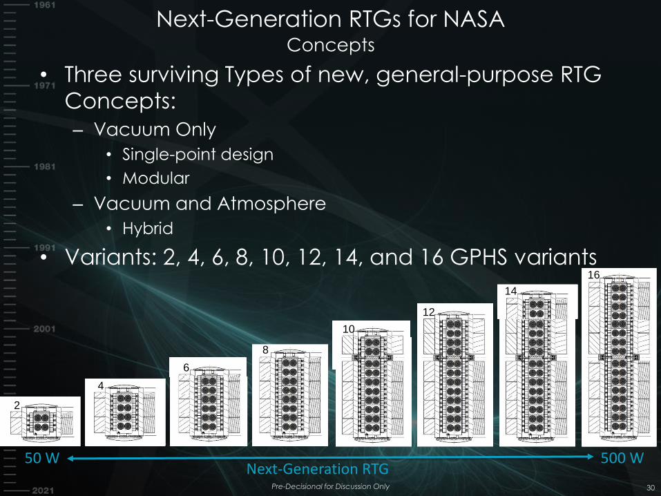
Next-Generation RTGs for NASA Concepts
• Three surviving Types of new, general-purpose RTG
Concepts:
– Vacuum Only
• Single-point design
• Modular
– Vacuum and Atmosphere
• Hybrid
• Variants: 2, 4, 6, 8, 10, 12, 14, and 16 GPHS variants
Pre-Decisional for Discussion Only 30
2
4
6
8
10
12
16
14
50 W 500 W Next-Generation RTG
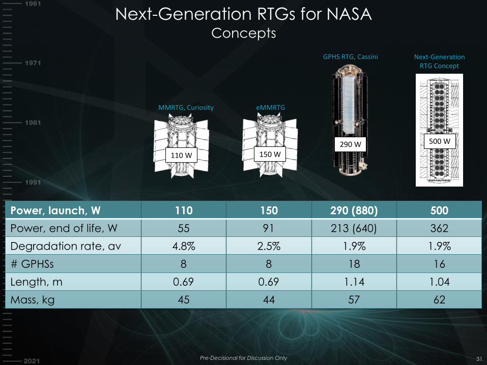
Next-Generation RTGs for NASA Concepts
Pre-Decisional for Discussion Only 31
Power, launch, W 110 150 290 (880) 500
Power, end of life, W 55 91 213 (640) 362
Degradation rate, av 4.8% 2.5% 1.9% 1.9%
# GPHSs 8 8 18 16
Length, m 0.69 0.69 1.14 1.04
Mass, kg 45 44 57 62
150 W
eMMRTG
290 W
GPHS RTG, Cassini
110 W
MMRTG, Curiosity
Next-Generation RTG Concept
500 W
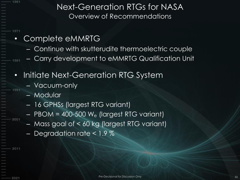
Next-Generation RTGs for NASA Overview of Recommendations
• Complete eMMRTG
– Continue with skutterudite thermoelectric couple
– Carry development to eMMRTG Qualification Unit
• Initiate Next-Generation RTG System
– Vacuum-only
– Modular
– 16 GPHSs (largest RTG variant)
– PBOM = 400-500 We (largest RTG variant)
– Mass goal of < 60 kg (largest RTG variant)
– Degradation rate < 1.9 %
Pre-Decisional for Discussion Only 32
TE MATERIALS AND TECHNOLOGY
RADIOISOTOPE POWER SYSTEMS PROGRAM
33 Pre-Decisional for Discussion Only
Outline
• Approach for Next Generation RTG
Technology Evaluation
• TE technologies for RPS: background
• Advanced TE technologies for Next-
Generation RTG study
• Summary
34 Pre-Decisional for Discussion Only
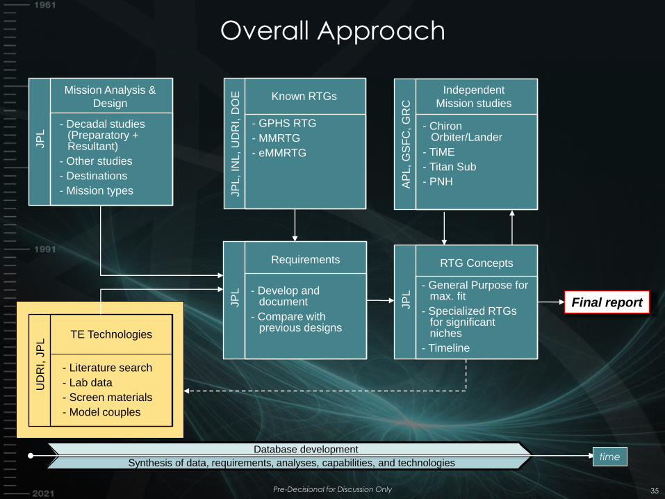
Overall Approach
Pre-Decisional for Discussion Only 35
time
Mission Analysis &
Design
- Decadal studies (Preparatory + Resultant)
- Other studies
- Destinations
- Mission types
JP
L
TE Technologies
- Literature search
- Lab data
- Screen materials
- Model couples
UD
RI, J
PL
Requirements
- Develop and document
- Compare with previous designs
JP
L
Known RTGs
- GPHS RTG
- MMRTG
- eMMRTG
JP
L, IN
L,
UD
RI, D
OE
Independent
Mission studies
- Chiron Orbiter/Lander
- TiME
- Titan Sub
- PNH AP
L, G
SF
C, G
RC
RTG Concepts
- General Purpose for max. fit
- Specialized RTGs for significant niches
- Timeline
JP
L
Database development
Synthesis of data, requirements, analyses, capabilities, and technologies
Final report
time
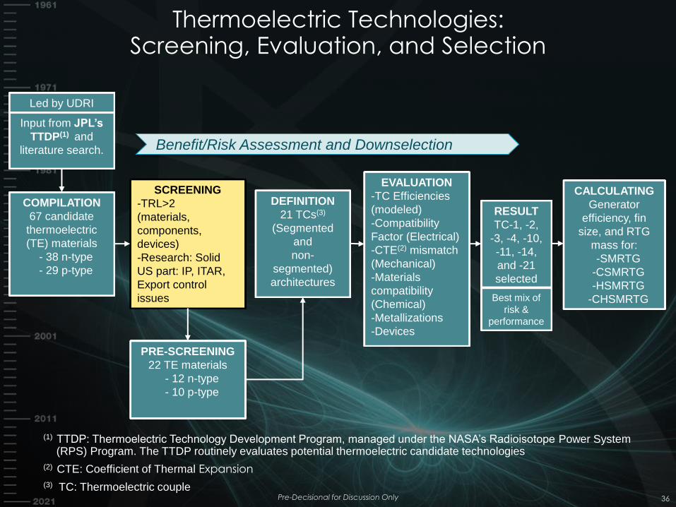
Led by UDRI
Thermoelectric Technologies: Screening, Evaluation, and Selection
Pre-Decisional for Discussion Only 36
COMPILATION
67 candidate
thermoelectric
(TE) materials
- 38 n-type
- 29 p-type
Input from JPL’s
TTDP(1) and
literature search.
(1) TTDP: Thermoelectric Technology Development Program, managed under the NASA’s Radioisotope Power System (RPS) Program. The TTDP routinely evaluates potential thermoelectric candidate technologies
(2) CTE: Coefficient of Thermal Expansion
(3) TC: Thermoelectric couple
SCREENING
-TRL>2
(materials,
components,
devices)
-Research: Solid
US part: IP, ITAR,
Export control
issues
PRE-SCREENING
22 TE materials
- 12 n-type
- 10 p-type
RESULT
TC-1, -2,
-3, -4, -10,
-11, -14,
and -21
selected
DEFINITION
21 TCs(3)
(Segmented
and
non-
segmented)
architectures
EVALUATION
-TC Efficiencies
(modeled)
-Compatibility
Factor (Electrical)
-CTE(2) mismatch
(Mechanical)
-Materials
compatibility
(Chemical)
-Metallizations
-Devices
CALCULATING
Generator
efficiency, fin
size, and RTG
mass for:
-SMRTG
-CSMRTG
-HSMRTG
-CHSMRTG
Benefit/Risk Assessment and Downselection
Best mix of
risk &
performance
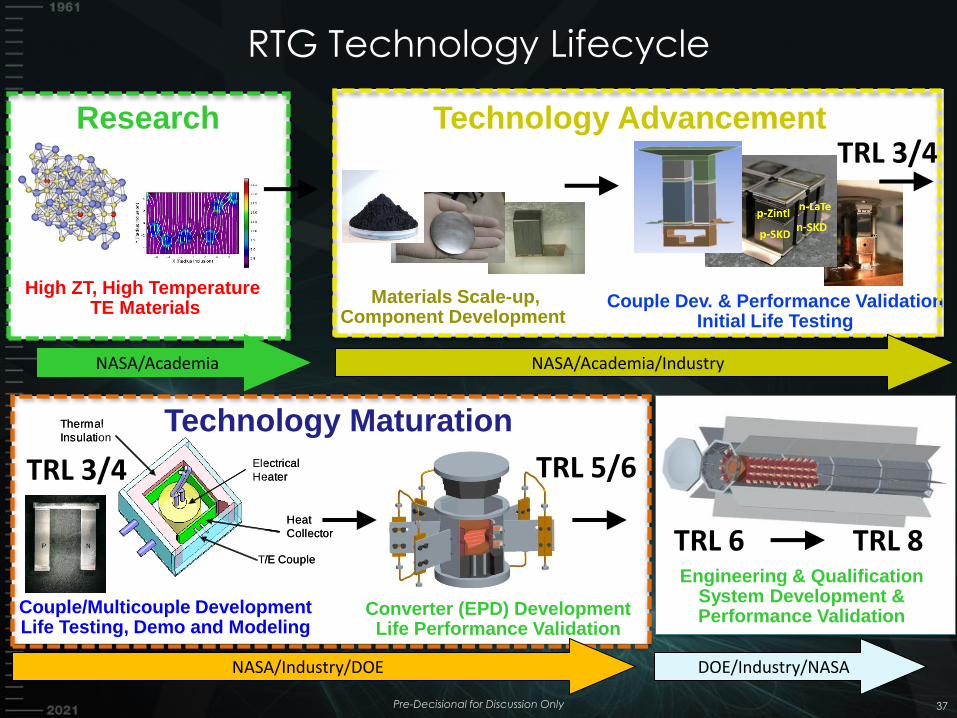
RTG Technology Lifecycle
Pre-Decisional for Discussion Only 37
Engineering & Qualification System Development & Performance Validation
High ZT, High Temperature TE Materials
Materials Scale-up, Component Development
Couple Dev. & Performance Validation Initial Life Testing
Couple/Multicouple Development Life Testing, Demo and Modeling
Converter (EPD) Development Life Performance Validation
Electrical
Heater
Thermal
Insulation
Heat
Collector
T/E Couple
Electrical
Heater
Thermal
Insulation
Heat
Collector
T/E Couple
DOE/Industry/NASA
Technology Advancement
TRL 0-2
Research
Technology Maturation
NASA/Industry/DOE
TRL 2 TRL 3/4
TRL 3/4 TRL 5/6
TRL 6 TRL 8
NASA/Academia NASA/Academia/Industry
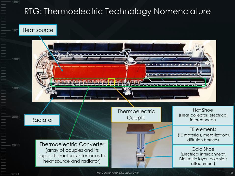
RTG: Thermoelectric Technology Nomenclature
Pre-Decisional for Discussion Only 38
Heat source
Radiator
Thermoelectric
Couple
Thermoelectric Converter (array of couples and its
support structure/interfaces to heat source and radiator)
Cold Shoe (Electrical interconnect,
Dielectric layer, cold side
attachment)
TE elements (TE materials, metallizations,
diffusion barriers)
Hot Shoe (Heat collector, electrical
interconnect)
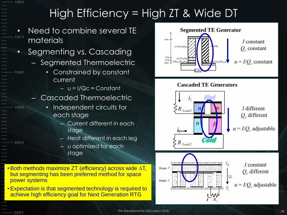
High Efficiency = High ZT & Wide DT
39
Load
p-CeFe4Sb12n-CoSb3
p--Zn4Sb3
p-Bi0.4Sb1.6Te3 n-Bi2Te2.95Se0.05300K
475K
975K
675K
I constant
Qc constant
u = I/Qc constant
Segmented TE Generator
Cascaded TE Generators
I different
Qc different
u = I/Qc adjustable
Hot
Cold
n p
i1
R Load,1
n p
R Load,2
i2
I constant
Qc different
u = I/Qc adjustable
• Both methods maximize ZT (efficiency) across wide DT, but segmenting has been preferred method for space power systems
• Expectation is that segmented technology is required to achieve high efficiency goal for Next Generation RTG
• Need to combine several TE
materials
• Segmenting vs. Cascading
– Segmented Thermoelectric
• Constrained by constant
current
– u = I/Qc ≈ Constant
– Cascaded Thermoelectric
• Independent circuits for
each stage
– Current different in each stage
– Heat different in each leg
– u optimized for each
stage
Pre-Decisional for Discussion Only
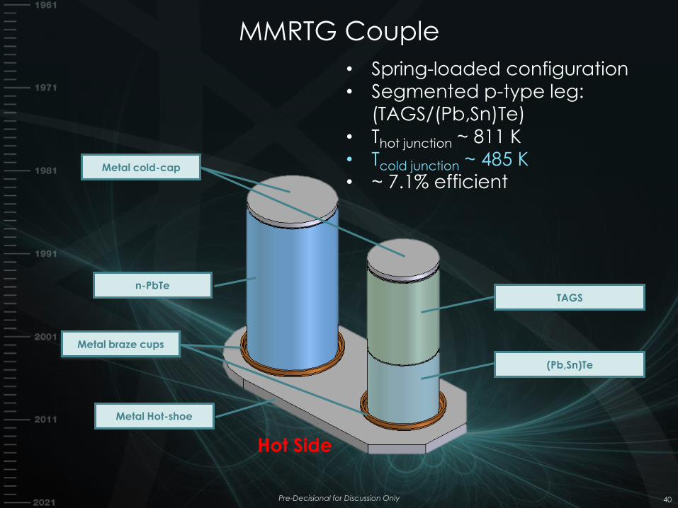
Metal Hot-shoe
Metal braze cups
n-PbTe
Metal cold-cap
(Pb,Sn)Te
TAGS
• Spring-loaded configuration
• Segmented p-type leg:
(TAGS/(Pb,Sn)Te)
• Thot junction ~ 811 K • Tcold junction ~ 485 K
• ~ 7.1% efficient
Hot Side
MMRTG Couple
Pre-Decisional for Discussion Only 40
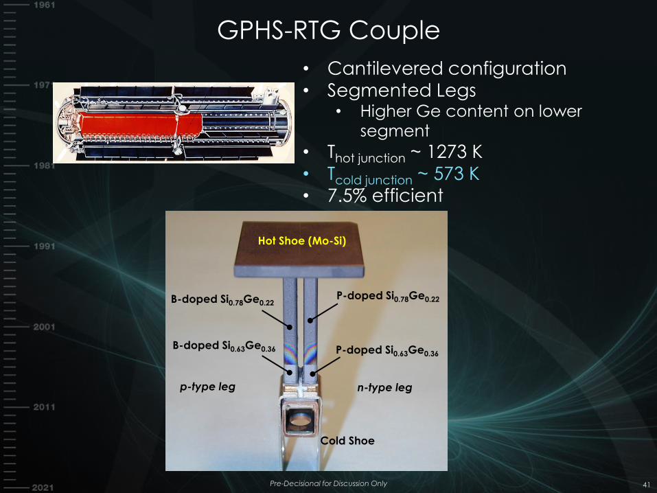
GPHS-RTG Couple
Pre-Decisional for Discussion Only 41
B-doped Si0.78Ge0.22 P-doped Si0.78Ge0.22
B-doped Si0.63Ge0.36 P-doped Si0.63Ge0.36
Hot Shoe (Mo-Si)
Cold Shoe
n-type leg p-type leg
• Cantilevered configuration • Segmented Legs
• Higher Ge content on lower
segment
• Thot junction ~ 1273 K
• Tcold junction ~ 573 K
• 7.5% efficient
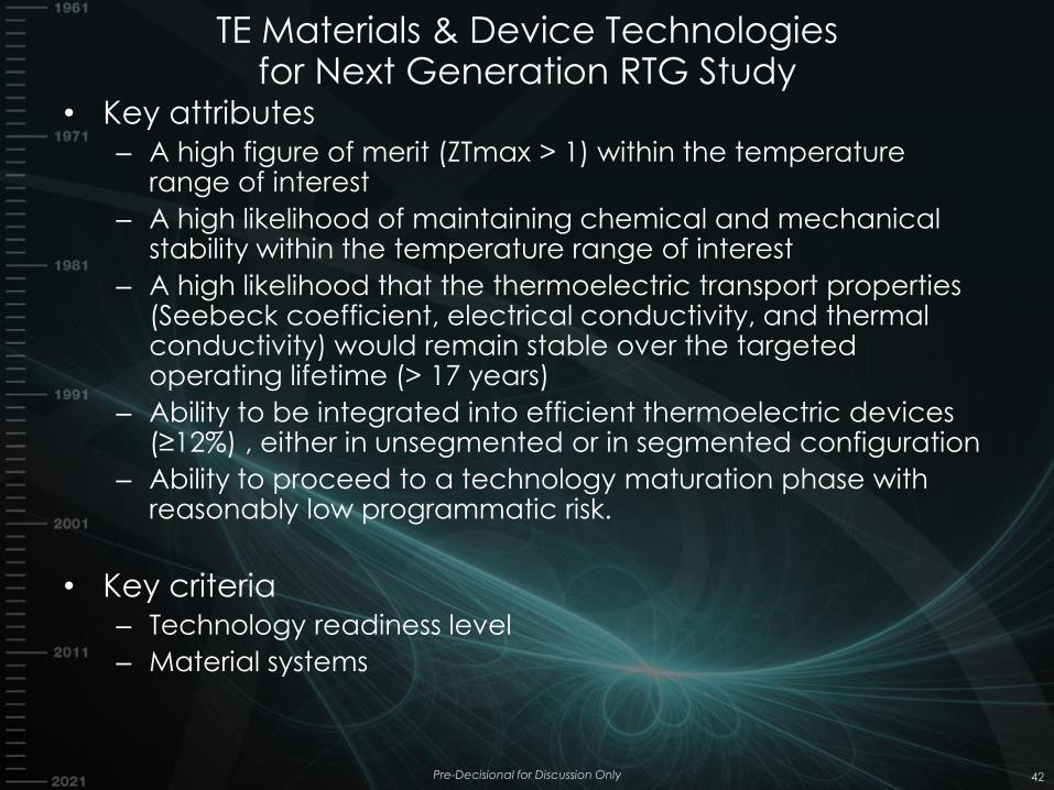
TE Materials & Device Technologies for Next Generation RTG Study
• Key attributes – A high figure of merit (ZTmax > 1) within the temperature
range of interest
– A high likelihood of maintaining chemical and mechanical stability within the temperature range of interest
– A high likelihood that the thermoelectric transport properties (Seebeck coefficient, electrical conductivity, and thermal conductivity) would remain stable over the targeted operating lifetime (> 17 years)
– Ability to be integrated into efficient thermoelectric devices (≥12%) , either in unsegmented or in segmented configuration
– Ability to proceed to a technology maturation phase with reasonably low programmatic risk.
• Key criteria – Technology readiness level
– Material systems
Pre-Decisional for Discussion Only 42
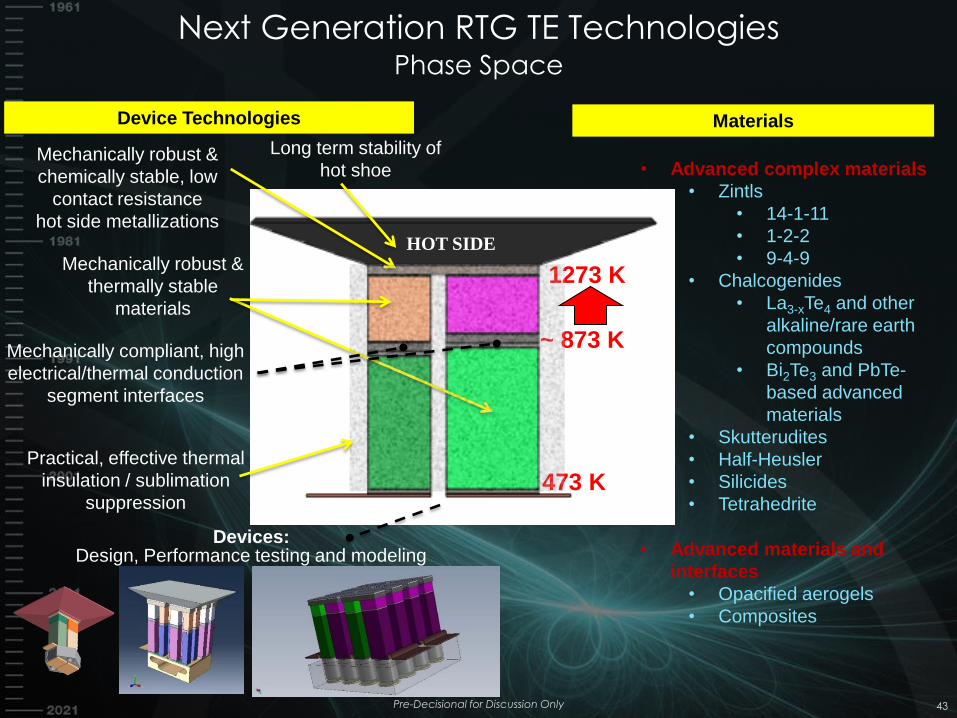
Next Generation RTG TE Technologies Phase Space
Pre-Decisional for Discussion Only 43
Long term stability of
hot shoe Mechanically robust &
chemically stable, low
contact resistance
hot side metallizations
1273 K
473 K
~ 873 K Mechanically compliant, high
electrical/thermal conduction
segment interfaces
Practical, effective thermal
insulation / sublimation
suppression
HOT SIDE Mechanically robust &
thermally stable
materials
Devices: Design, Performance testing and modeling
Device Technologies Materials
• Advanced complex materials
• Zintls
• 14-1-11
• 1-2-2
• 9-4-9
• Chalcogenides
• La3-xTe4 and other
alkaline/rare earth
compounds
• Bi2Te3 and PbTe-
based advanced
materials
• Skutterudites
• Half-Heusler
• Silicides
• Tetrahedrite
• Advanced materials and
interfaces
• Opacified aerogels
• Composites
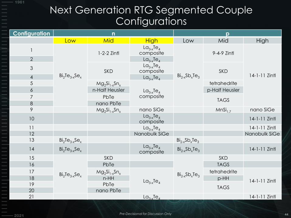
Next Generation RTG Segmented Couple Configurations
44
Configuration n p
Low Mid High Low Mid High
1
Bi2Te3-xSex
1-2-2 Zintl La3-xTe4
composite
Bi2-xSbxTe3
9-4-9 Zintl
14-1-11 Zintl
2 La3-xTe4
3 SKD
La3-xTe4 composite SKD
4 La3-xTe4
5 Mg2Si1-xSnx
La3-xTe4 composite
tetrahedrite
6 n-Half Heusler p-Half Heusler
7 PbTe TAGS
8 nano PbTe
9 Mg2Si1-xSnx nano SiGe MnSi1.7 nano SiGe
10 La3-xTe4
composite 14-1-11 Zintl
11 La3-xTe4 14-1-11 Zintl 12 Nanobulk SiGe Nanobulk SiGe
13 Bi2Te3-xSex Bi2-xSbxTe3
14 Bi2Te3-xSex La3-xTe4
composite Bi2-xSbxTe3 14-1-11 Zintl
15
Bi2Te3-xSex
SKD
Bi2-xSbxTe3
SKD
16 PbTe TAGS
17 Mg2Si1-xSnx
La3-xTe4
tetrahedrite
14-1-11 Zintl 18 n-HH p-HH
19 PbTe TAGS
20 nano PbTe
21 La3-xTe4 14-1-11 Zintl
Pre-Decisional for Discussion Only
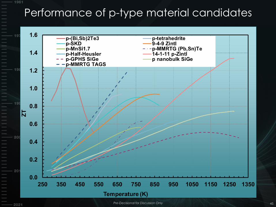
Performance of p-type material candidates
45 Pre-Decisional for Discussion Only
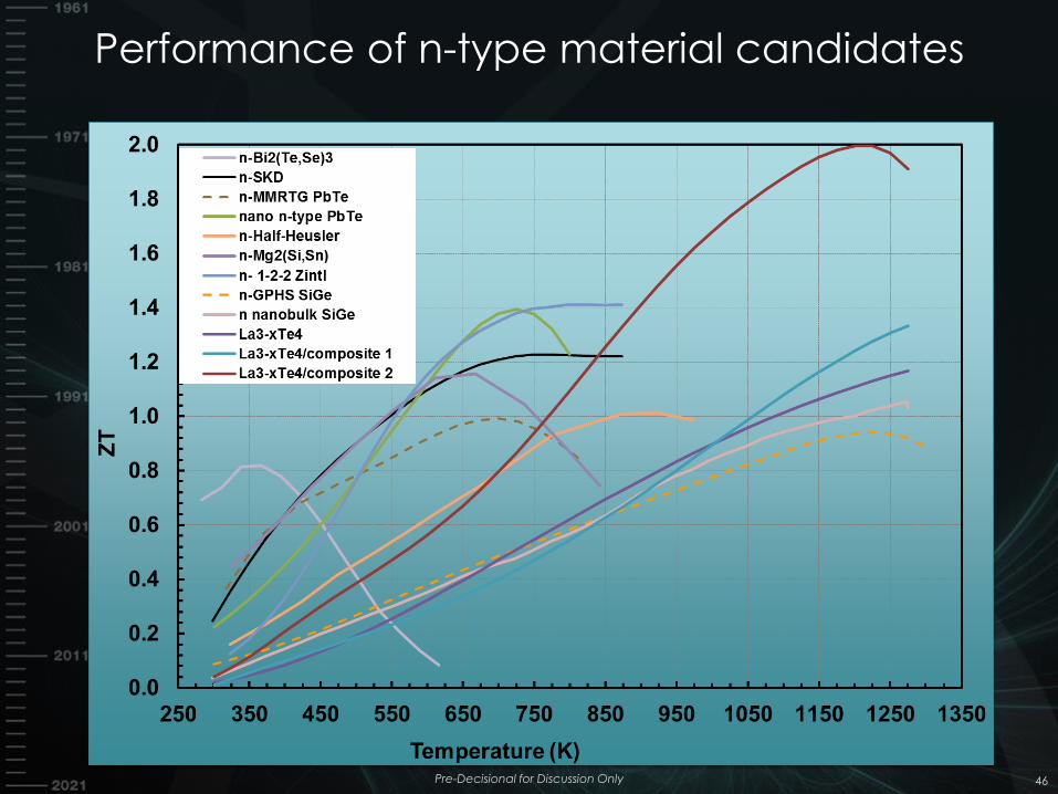
Performance of n-type material candidates
46 Pre-Decisional for Discussion Only
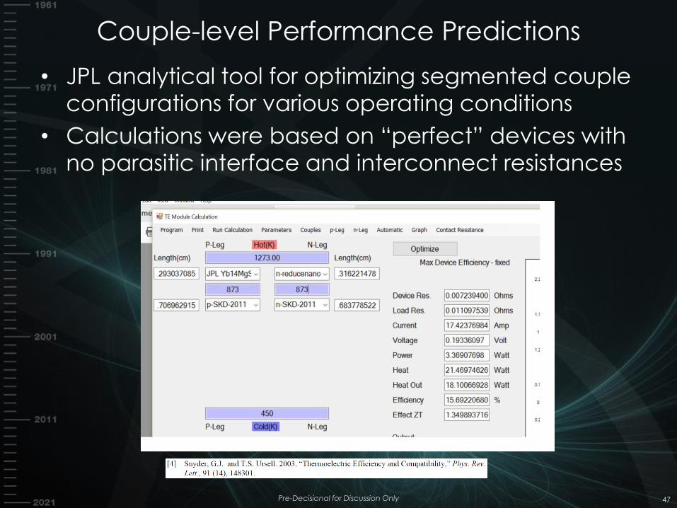
Couple-level Performance Predictions
• JPL analytical tool for optimizing segmented couple
configurations for various operating conditions
• Calculations were based on “perfect” devices with
no parasitic interface and interconnect resistances
Pre-Decisional for Discussion Only 47
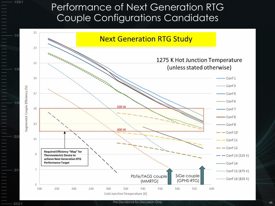
Performance of Next Generation RTG Couple Configurations Candidates
48
SiGe couple (GPHS-RTG)
PbTe/TAGS couple (MMRTG)
Required Efficiency “Map” for Thermoelectric Device to achieve Next Generation RTG Performance Target
400 W
500 W
Pre-Decisional for Discussion Only
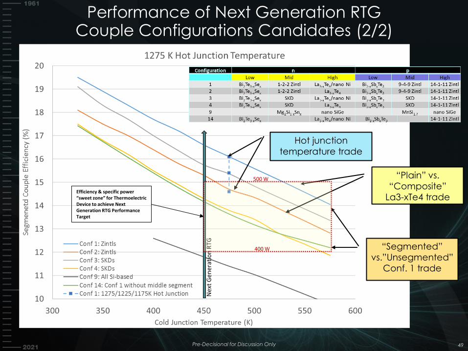
Performance of Next Generation RTG Couple Configurations Candidates (2/2)
49
Ne
xt G
ener
atio
n R
TG
Hot junction
temperature trade
“Plain” vs. “Composite”
La3-xTe4 trade
“Segmented” vs.”Unsegmented”
Conf. 1 trade
Efficiency & specific power “sweet zone” for Thermoelectric Device to achieve Next Generation RTG Performance Target
500 W
400 W
Pre-Decisional for Discussion Only
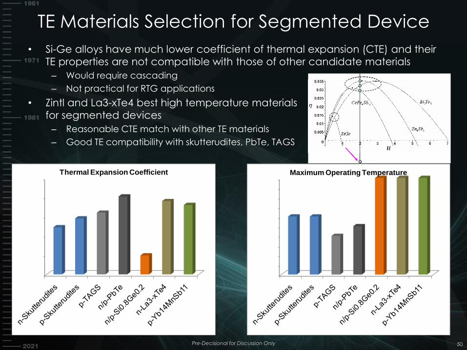
TE Materials Selection for Segmented Device
• Si-Ge alloys have much lower coefficient of thermal expansion (CTE) and their
TE properties are not compatible with those of other candidate materials
– Would require cascading
– Not practical for RTG applications
• Zintl and La3-xTe4 best high temperature materials
for segmented devices
– Reasonable CTE match with other TE materials
– Good TE compatibility with skutterudites, PbTe, TAGS
Pre-Decisional for Discussion Only 50
Thermal Expansion Coefficient Maximum Operating Temperature
Device Component Technology Survey
• Conducted a survey of device technology development for relevant materials under consideration
• TRL > 2 requires initial development and testing of components and devices – Requires at a minimum development of basic metallization schemes – Some of these materials have been successfully integrated into
devices – All of the recent work to date on materials and components for
operation above 1000 K has been carried by or in collaboration with NASA/JPL
• Higher TRL would provide extended (months to years) performance data on: – TE Materials – transport properties
– Ability to control sublimation rate to acceptable level – Demonstration of slow degradation rate kinetics for key interfaces in
device – Ability to integrate with thermal insulation – Ability to operate in relevant environment
Pre-Decisional for Discussion Only 51
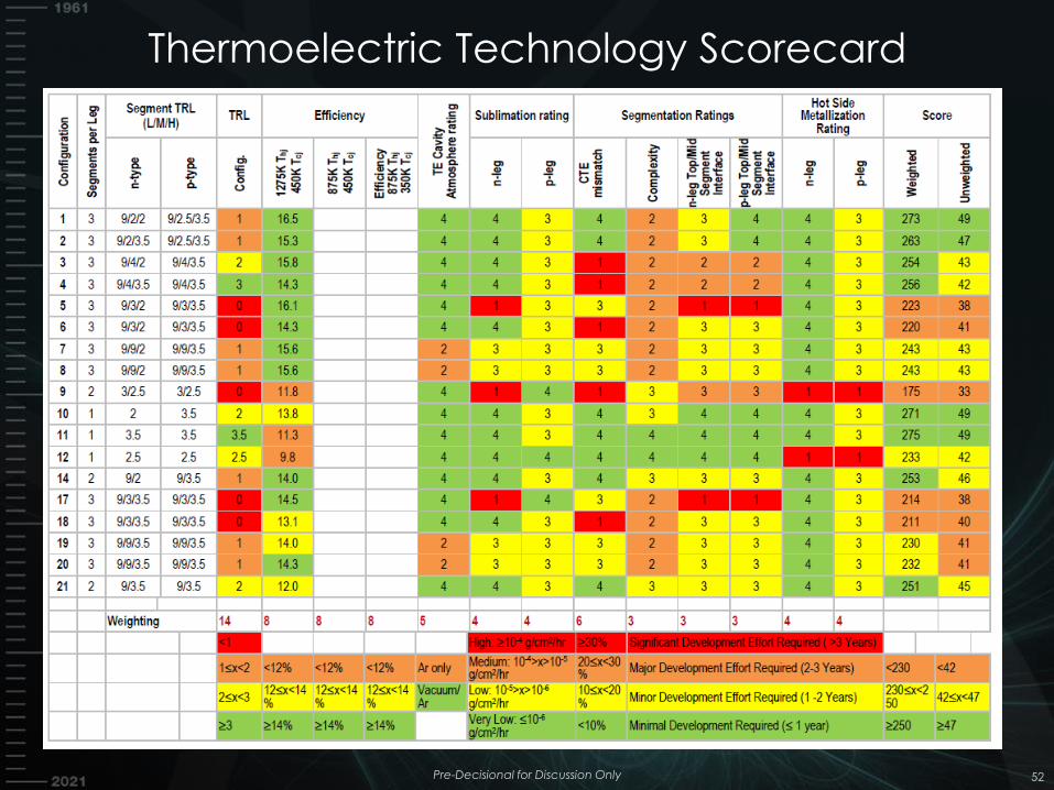
Thermoelectric Technology Scorecard
Pre-Decisional for Discussion Only 52
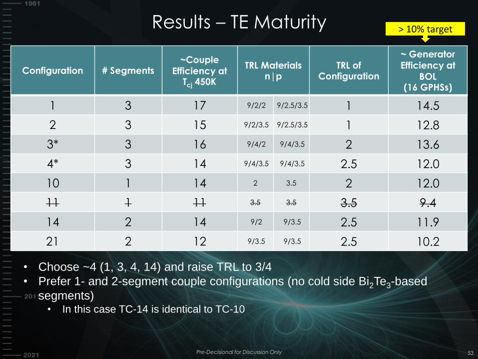
Results – TE Maturity
Pre-Decisional for Discussion Only 53
Configuration # Segments ~Couple
Efficiency at Tcj 450K
TRL Materials n|p
TRL of Configuration
~ Generator Efficiency at
BOL (16 GPHSs)
1 3 17 9/2/2 9/2.5/3.5 1 14.5
2 3 15 9/2/3.5 9/2.5/3.5 1 12.8
3* 3 16 9/4/2 9/4/3.5 2 13.6
4* 3 14 9/4/3.5 9/4/3.5 2.5 12.0
10 1 14 2 3.5 2 12.0
11 1 11 3.5 3.5 3.5 9.4
14 2 14 9/2 9/3.5 2.5 11.9
21 2 12 9/3.5 9/3.5 2.5 10.2
• Choose ~4 (1, 3, 4, 14) and raise TRL to 3/4
• Prefer 1- and 2-segment couple configurations (no cold side Bi2Te3-based
segments) • In this case TC-14 is identical to TC-10
> 10% target
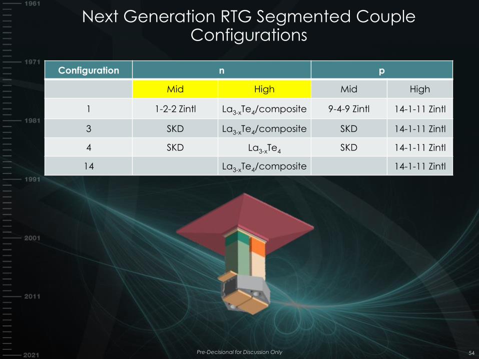
Next Generation RTG Segmented Couple Configurations
54
Configuration n p
Mid High Mid High
1 1-2-2 Zintl La3-xTe4/composite 9-4-9 Zintl 14-1-11 Zintl
3 SKD La3-xTe4/composite SKD 14-1-11 Zintl
4 SKD La3-xTe4 SKD 14-1-11 Zintl
14 La3-xTe4/composite 14-1-11 Zintl
Pre-Decisional for Discussion Only
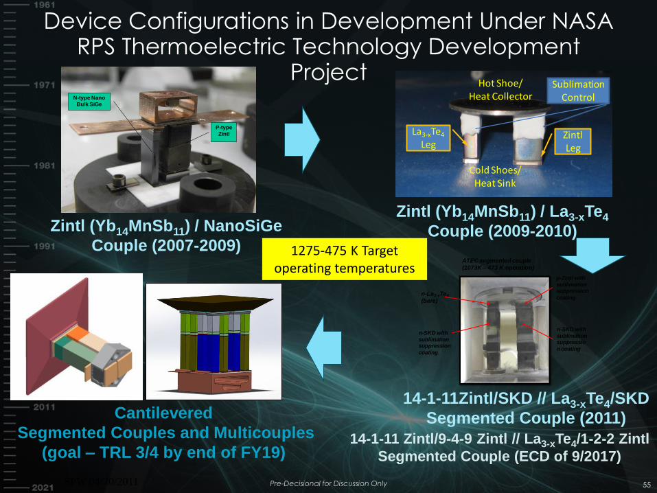
Zintl Leg
La3-xTe4
Leg
Hot Shoe/Heat Collector
Cold Shoes/Heat Sink
Sublimation Control
Zintl (Yb14MnSb11) / NanoSiGe
Couple (2007-2009)
Zintl (Yb14MnSb11) / La3-xTe4
Couple (2009-2010)
P-type
Zintl
N-type Nano
Bulk SiGe
14-1-11Zintl/SKD // La3-xTe4/SKD
Segmented Couple (2011)
14-1-11 Zintl/9-4-9 Zintl // La3-xTe4/1-2-2 Zintl
Segmented Couple (ECD of 9/2017)
p-Zintl with
sublimation suppression
coating
n-SKD with
sublimation suppressio
n coating
n-SKD with
sublimation suppression
coating
n-La3-xTe4
(bare)
ATEC segmented couple
(1073K – 473 K operation)
Cantilevered
Segmented Couples and Multicouples
(goal – TRL 3/4 by end of FY19)
SPW 04/20/2011
1275-475 K Target operating temperatures
Device Configurations in Development Under NASA RPS Thermoelectric Technology Development
Project
Pre-Decisional for Discussion Only 55
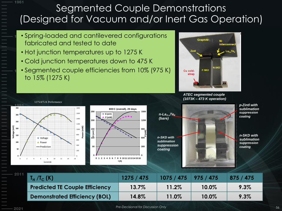
• Spring-loaded and cantilevered configurations
fabricated and tested to date
• Hot junction temperatures up to 1275 K
• Cold junction temperatures down to 475 K
• Segmented couple efficiencies from 10% (975 K)
to 15% (1275 K)
Segmented Couple Demonstrations (Designed for Vacuum and/or Inert Gas Operation)
Pre-Decisional for Discussion Only 56
0
200
400
600
800
1000
1200
1400
1600
1800
0
50
100
150
200
250
300
350
0 2 4 6 8 10 12 14 16
Po
we
r (m
W)
Vo
ltag
e (m
V)
Current (A)
Voltage
Power
Prediction
0
300
600
900
1200
1500
0
50
100
150
200
250
0 1 2 3 4 5 6 7 8 9 10 11 12 13 14 15 16
P (m
W)
E (m
V)
I (A)
800 C (overall), 20 days
E (mV)
P (mW)
TH /TC (K) 1275 / 475 1075 / 475 975 / 475 875 / 475
Predicted TE Couple Efficiency 13.7% 11.2% 10.0% 9.3%
Demonstrated Efficiency (BOL) 14.8% 11.0% 10.0% 9.3%
1275/475 K Performance
p - Zintl with sublimation suppression
coating
n - SKD with sublimation suppression
coating
n - SKD with
sublimation
suppression coating
n - La 3 - x Te 4
(bare)
ATEC segmented couple
(1073K – 473 K operation)
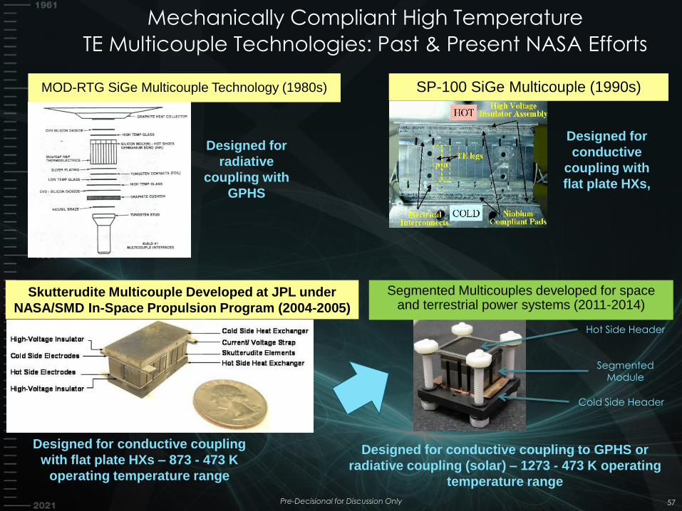
Mechanically Compliant High Temperature
TE Multicouple Technologies: Past & Present NASA Efforts
57
Skutterudite Multicouple Developed at JPL under
NASA/SMD In-Space Propulsion Program (2004-2005)
Designed for conductive coupling
with flat plate HXs – 873 - 473 K
operating temperature range
Designed for
conductive
coupling with
flat plate HXs,
Designed for
radiative
coupling with
GPHS
SP-100 SiGe Multicouple (1990s) MOD-RTG SiGe Multicouple Technology (1980s)
Segmented Multicouples developed for space and terrestrial power systems (2011-2014)
Designed for conductive coupling to GPHS or
radiative coupling (solar) – 1273 - 473 K operating
temperature range
Hot Side Header
Cold Side Header
Segmented Module
Pre-Decisional for Discussion Only
NOTE: Graphics not to scale
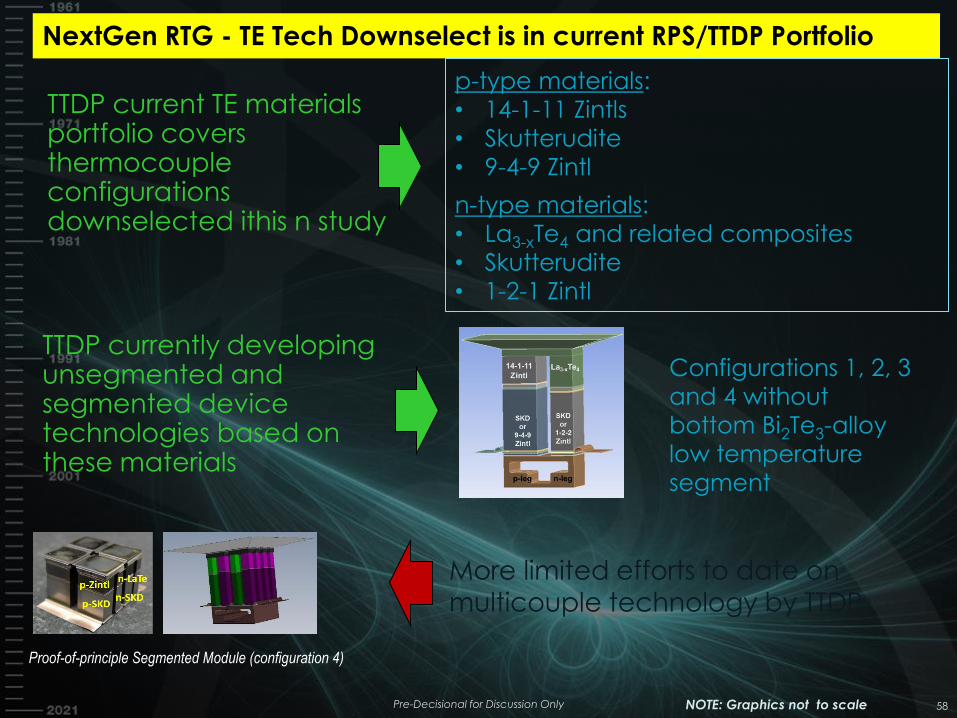
NextGen RTG - TE Tech Downselect is in current RPS/TTDP Portfolio
Proof-of-principle Segmented Module (configuration 4)
p-type materials:
• 14-1-11 Zintls
• Skutterudite
• 9-4-9 Zintl
n-type materials:
• La3-xTe4 and related composites
• Skutterudite
• 1-2-1 Zintl
TTDP current TE materials portfolio covers thermocouple configurations downselected ithis n study
TTDP currently developing unsegmented and segmented device technologies based on these materials
Configurations 1, 2, 3
and 4 without
bottom Bi2Te3-alloy
low temperature
segment
More limited efforts to date on multicouple technology by TTDP
Pre-Decisional for Discussion Only 58
Summary & Recommendation
• Evaluated 3-Segment, 2-Segment and 1-Segment Configurations – Materials-level efficiencies as high as 17% for 450 K cold
junction temperature and 1273 K hot junction temperature
– Efficiency decreases (model predicted) as number of segments decreases
– System degradation rate of 1.9% assumed for all configurations
– Risks decreases as number of segments decreases
• 8 different TE configurations modeled in generator concepts – Several of these meet the > 12% efficiency target for
thermoelectric couples
– These configurations are under development by NASA
Pre-Decisional for Discussion Only 59
NASA CONCEPTUAL PLAN FORWARD
RADIOISOTOPE POWER SYSTEMS PROGRAM
60 Pre-Decisional for Discussion Only
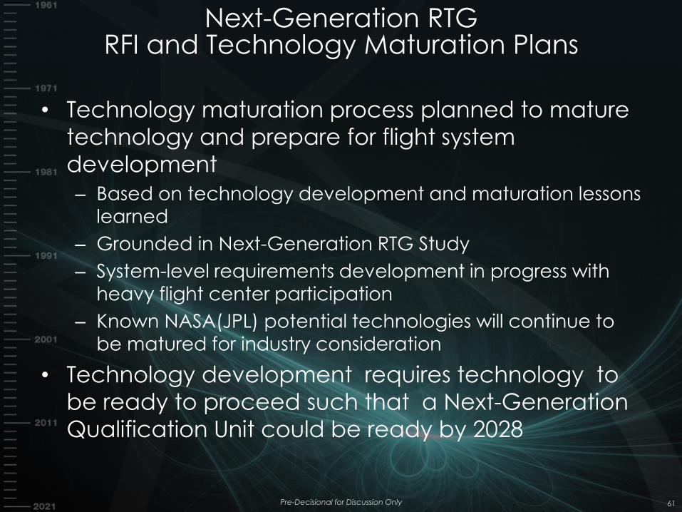
Next-Generation RTG RFI and Technology Maturation Plans
• Technology maturation process planned to mature
technology and prepare for flight system
development
– Based on technology development and maturation lessons
learned
– Grounded in Next-Generation RTG Study
– System-level requirements development in progress with
heavy flight center participation
– Known NASA(JPL) potential technologies will continue to
be matured for industry consideration
• Technology development requires technology to
be ready to proceed such that a Next-Generation
Qualification Unit could be ready by 2028
Pre-Decisional for Discussion Only 61
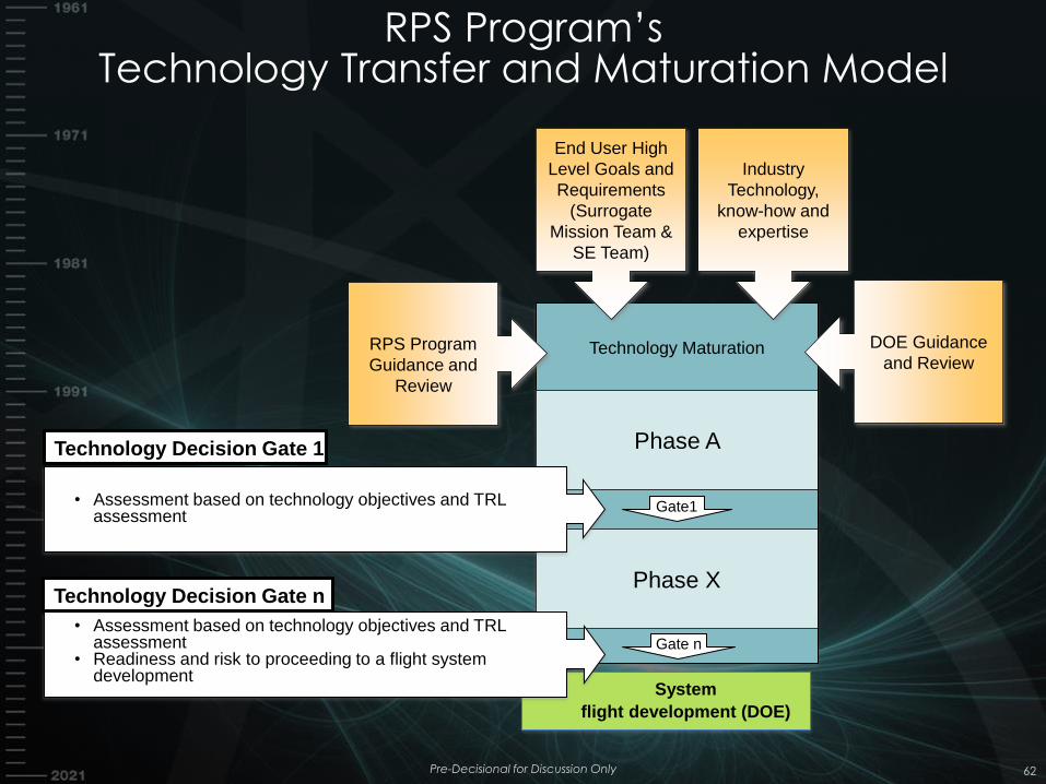
RPS Program’s Technology Transfer and Maturation Model
Pre-Decisional for Discussion Only 62
Technology Maturation
Phase X
Phase A
Gate1
Gate n
System
flight development (DOE)
RPS Program
Guidance and
Review
DOE Guidance
and Review
Industry
Technology,
know-how and
expertise
End User High
Level Goals and
Requirements
(Surrogate
Mission Team &
SE Team)
• Assessment based on technology objectives and TRL assessment
Technology Decision Gate 1
• Assessment based on technology objectives and TRL assessment
• Readiness and risk to proceeding to a flight system development
Technology Decision Gate n
What Are We Looking For?
• Potential technologies to lead to a Next-Generation RTG that would meet the top level driving requirement
• Dialog with the community on industry needs regarding NASA TE technology investments
• Response to the RFI
• Feedback on draft RFP
Pre-Decisional for Discussion Only 63
Next-Gen RTG Top Driving Requirements
• System designed to operate in vacuum
• System designed to be modular
– Requires process for modular qualification
• System (16 GPHS) provides at least 400 We at BOL
with a goal of 500 We
• System (16 GPHS) mass is 60 kg or less
• System degradation rate, including fuel
degradation, projected to be 1.9%
– To be rewritten in terms of EODL power
• System to be designed to be upgraded with new
TCs as technology matures
Pre-Decisional for Discussion Only •64
Plan Forward
• System concept driven TE technology plan
• Technology includes TE technology and associated
technology (e.g. insulation)
• JPL materials and TE information to be made
available
– Details being worked
• Three Technology Phases with Gates
– Phase I Technology Advancement
– Phase II Technology Maturation
– Phase III Government evaluation phase
• If technology is deemed mature to proceed – DOE
System Development Contract to Qualification unit
by 2028
Pre-Decisional for Discussion Only 65
Timeline
• Preparation & Discovery Phase – June 2017 to March
2018
– RFI (Fall 2017)*
– Acquisition Strategy
– Industry Day(s) (Fall 2017)*
– Draft functional requirements and technology requirements
– Continued investment in NASA potential TE technology
• Technology Phase – March 2018 to October 22*
– RFP
– Multiple Awards
– Technology development anchored to potential Next
Generation RTG system concept
– Assessment of technology readiness for system development
• System Development Phase to Qualification Unit – 2023
to 2028
Pre-Decisional for Discussion Only 66
*Tentative
DOE Led Phase
Summary of Draft RFI Requests
• Availability or potential availability of TE technology
options that could be utilized in a modular, 50-500 We
power system
• Understanding of current device(s) and state of
development
• TE device operation. Configuration, mass, performance,
operational temperature range, and fault tolerance.
• Number of applicable units produced, demonstrated life
and reliability, risks to achieve long operational life
• Scalability, if required. Projected performance
correlated with heat source degradation
• Experience with production of space-flight, nuclear
hardware, materials, components, devices, converters,
processes, Integration ,test, and QA
Pre-Decisional for Discussion Only 67
Summary of Information Requested
• What company assets/expertise will be utilized for
this activity
• What partnerships; i.e. other industry, NASA, other
will be used for the technology development,
hardware production, and test
• How will this capability be sustained during periods
of non-use by NASA
• Other
Pre-Decisional for Discussion Only 68
Q&A
RADIOISOTOPE POWER SYSTEMS PROGRAM
69
Find these charts at http://rps.nasa.gov
Pre-Decisional for Discussion Only
BACKUP CHARTS
71 Pre-Decisional for Discussion Only
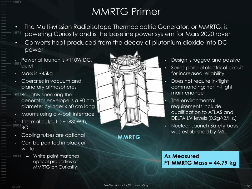
MMRTG Primer
• The Multi-Mission Radioisotope Thermoelectric Generator, or MMRTG, is powering Curiosity and is the baseline power system for Mars 2020 rover
• Converts heat produced from the decay of plutonium dioxide into DC power
MMRTG
• Power at launch is >110W DC,
quiet
• Mass is ~45kg
• Operates in vacuum and planetary atmospheres
• Roughly speaking the
generator envelope is a 60 cm diameter cylinder x 60 cm long
• Mounts using a 4-bolt interface
• Thermal output is ~1880Wth, BOL
• Cooling tubes are optional
• Can be painted in black or white
– White paint matches
optical properties of
MMRTG on Curiosity
• Design is rugged and passive
• Series-parallel electrical circuit for increased reliability
• Does not require in-flight commanding; nor in-flight maintenance
• The environmental requirements include qualification to ATLAS and DELTA LV levels (0.2g^2/Hz.)
• Nuclear Launch Safety basis
was established by MSL
As Measured
F1 MMRTG Mass = 44.79 kg
72 Pre-Decisional for Discussion Only
Next-Generation RTGs for NASA Mission Analyses (MA)
• A few additional requirements flowing from the missions flown and studied
• Mission Length
• Radiation
• Descent and Landing
• Micrometeoroids
• Atmospheric pressure and atmospheric constituents
• Environmental temperatures
Pre-Decisional for Discussion Only 73
Next-Generation RTGs for NASA Mission Analyses
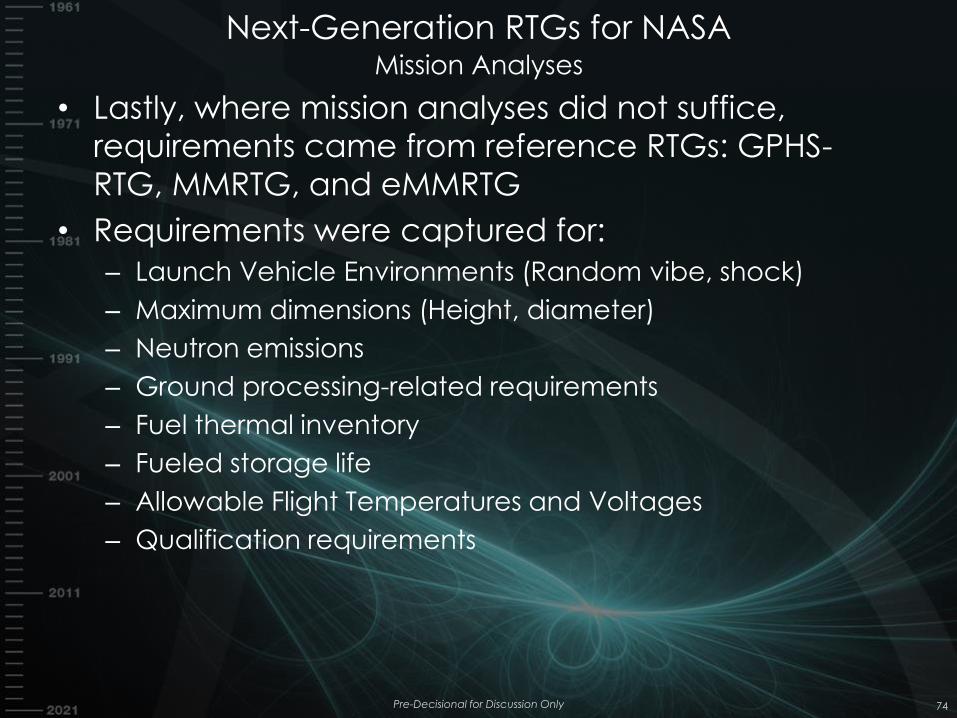
• Lastly, where mission analyses did not suffice,
requirements came from reference RTGs: GPHS-
RTG, MMRTG, and eMMRTG
• Requirements were captured for:
– Launch Vehicle Environments (Random vibe, shock)
– Maximum dimensions (Height, diameter)
– Neutron emissions
– Ground processing-related requirements
– Fuel thermal inventory
– Fueled storage life
– Allowable Flight Temperatures and Voltages
– Qualification requirements
Pre-Decisional for Discussion Only 74
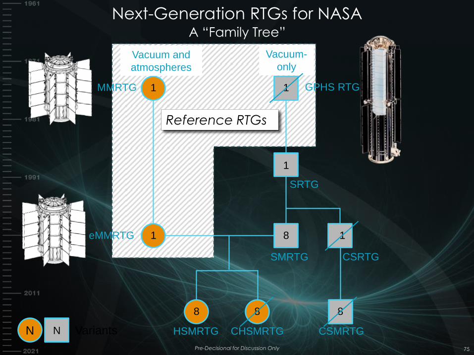
Next-Generation RTGs for NASA A “Family Tree”
Pre-Decisional for Discussion Only 75
MMRTG
eMMRTG
GPHS RTG
SRTG
CSRTG SMRTG
CSMRTG CHSMRTG HSMRTG
Vacuum and
atmospheres
Vacuum-
only
1
1
1
1
1 8
8 8 8
N Variants N
Reference RTGs
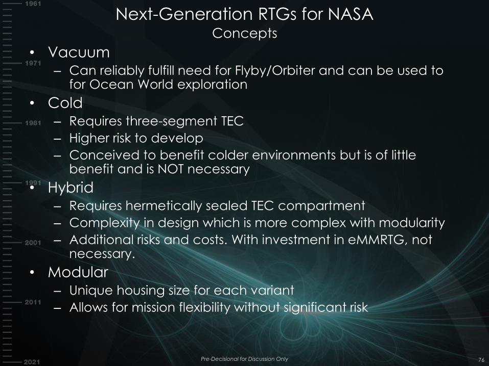
Next-Generation RTGs for NASA Concepts
• Vacuum – Can reliably fulfill need for Flyby/Orbiter and can be used to
for Ocean World exploration
• Cold – Requires three-segment TEC
– Higher risk to develop
– Conceived to benefit colder environments but is of little benefit and is NOT necessary
• Hybrid – Requires hermetically sealed TEC compartment
– Complexity in design which is more complex with modularity
– Additional risks and costs. With investment in eMMRTG, not necessary.
• Modular – Unique housing size for each variant
– Allows for mission flexibility without significant risk
Pre-Decisional for Discussion Only 76
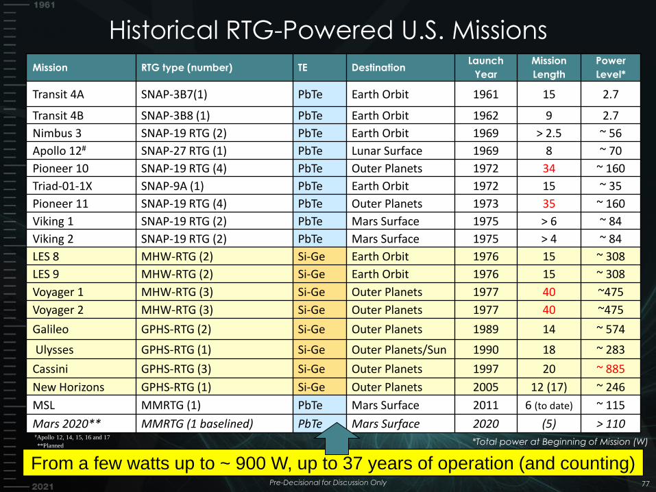
Mission RTG type (number) TE Destination Launch
Year
Mission
Length
Power
Level*
Transit 4A SNAP-3B7(1) PbTe Earth Orbit 1961 15 2.7
Transit 4B SNAP-3B8 (1) PbTe Earth Orbit 1962 9 2.7
Nimbus 3 SNAP-19 RTG (2) PbTe Earth Orbit 1969 > 2.5 ~ 56
Apollo 12# SNAP-27 RTG (1) PbTe Lunar Surface 1969 8 ~ 70
Pioneer 10 SNAP-19 RTG (4) PbTe Outer Planets 1972 34 ~ 160
Triad-01-1X SNAP-9A (1) PbTe Earth Orbit 1972 15 ~ 35
Pioneer 11 SNAP-19 RTG (4) PbTe Outer Planets 1973 35 ~ 160
Viking 1 SNAP-19 RTG (2) PbTe Mars Surface 1975 > 6 ~ 84
Viking 2 SNAP-19 RTG (2) PbTe Mars Surface 1975 > 4 ~ 84
LES 8 MHW-RTG (2) Si-Ge Earth Orbit 1976 15 ~ 308
LES 9 MHW-RTG (2) Si-Ge Earth Orbit 1976 15 ~ 308
Voyager 1 MHW-RTG (3) Si-Ge Outer Planets 1977 40 ~475
Voyager 2 MHW-RTG (3) Si-Ge Outer Planets 1977 40 ~475
Galileo GPHS-RTG (2) Si-Ge Outer Planets 1989 14 ~ 574
Ulysses GPHS-RTG (1) Si-Ge Outer Planets/Sun 1990 18 ~ 283
Cassini GPHS-RTG (3) Si-Ge Outer Planets 1997 20 ~ 885
New Horizons GPHS-RTG (1) Si-Ge Outer Planets 2005 12 (17) ~ 246
MSL MMRTG (1) PbTe Mars Surface 2011 6 (to date) ~ 115
Mars 2020** MMRTG (1 baselined) PbTe Mars Surface 2020 (5) > 110
From a few watts up to ~ 900 W, up to 37 years of operation (and counting)
**Planned *Total power at Beginning of Mission (W) #Apollo 12, 14, 15, 16 and 17
Historical RTG-Powered U.S. Missions
77 Pre-Decisional for Discussion Only
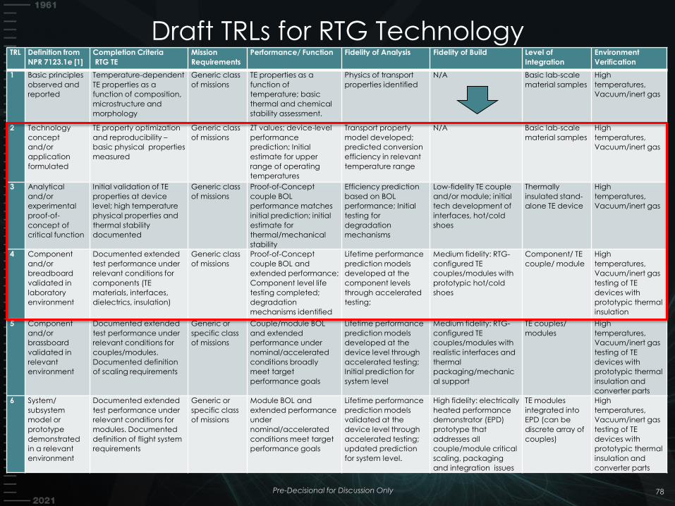
Draft TRLs for RTG Technology
78
TRL Definition from
NPR 7123.1e [1]
Completion Criteria
RTG TE
Mission
Requirements
Performance/ Function Fidelity of Analysis Fidelity of Build Level of
Integration
Environment
Verification
1 Basic principles
observed and
reported
Temperature-dependent
TE properties as a
function of composition,
microstructure and
morphology
Generic class
of missions
TE properties as a
function of
temperature; basic
thermal and chemical
stability assessment.
Physics of transport
properties identified
N/A Basic lab-scale
material samples
High
temperatures,
Vacuum/inert gas
2 Technology
concept
and/or
application
formulated
TE property optimization
and reproducibility –
basic physical properties
measured
Generic class
of missions
ZT values; device-level
performance
prediction; Initial
estimate for upper
range of operating
temperatures
Transport property
model developed;
predicted conversion
efficiency in relevant
temperature range
N/A Basic lab-scale
material samples
High
temperatures,
Vacuum/inert gas
3 Analytical
and/or
experimental
proof-of-
concept of
critical function
Initial validation of TE
properties at device
level; high temperature
physical properties and
thermal stability
documented
Generic class
of missions
Proof-of-Concept
couple BOL
performance matches
initial prediction; initial
estimate for
thermal/mechanical
stability
Efficiency prediction
based on BOL
performance; Initial
testing for
degradation
mechanisms
Low-fidelity TE couple
and/or module; initial
tech development of
interfaces, hot/cold
shoes
Thermally
insulated stand-
alone TE device
High
temperatures,
Vacuum/inert gas
4 Component
and/or
breadboard
validated in
laboratory
environment
Documented extended
test performance under
relevant conditions for
components (TE
materials, interfaces,
dielectrics, insulation)
Generic class
of missions
Proof-of-Concept
couple BOL and
extended performance;
Component level life
testing completed;
degradation
mechanisms identified
Lifetime performance
prediction models
developed at the
component levels
through accelerated
testing;
Medium fidelity: RTG-
configured TE
couples/modules with
prototypic hot/cold
shoes
Component/ TE
couple/ module
High
temperatures,
Vacuum/inert gas
testing of TE
devices with
prototypic thermal
insulation
5 Component
and/or
brassboard
validated in
relevant
environment
Documented extended
test performance under
relevant conditions for
couples/modules.
Documented definition
of scaling requirements
Generic or
specific class
of missions
Couple/module BOL
and extended
performance under
nominal/accelerated
conditions broadly
meet target
performance goals
Lifetime performance
prediction models
developed at the
device level through
accelerated testing;
Initial prediction for
system level
Medium fidelity: RTG-
configured TE
couples/modules with
realistic interfaces and
thermal
packaging/mechanic
al support
TE couples/
modules
High
temperatures,
Vacuum/inert gas
testing of TE
devices with
prototypic thermal
insulation and
converter parts
6 System/
subsystem
model or
prototype
demonstrated
in a relevant
environment
Documented extended
test performance under
relevant conditions for
modules. Documented
definition of flight system
requirements
Generic or
specific class
of missions
Module BOL and
extended performance
under
nominal/accelerated
conditions meet target
performance goals
Lifetime performance
prediction models
validated at the
device level through
accelerated testing;
updated prediction
for system level.
High fidelity: electrically
heated performance
demonstrator (EPD)
prototype that
addresses all
couple/module critical
scaling, packaging
and integration issues
TE modules
integrated into
EPD (can be
discrete array of
couples)
High
temperatures,
Vacuum/inert gas
testing of TE
devices with
prototypic thermal
insulation and
converter parts
Pre-Decisional for Discussion Only