Embed Size (px)
Citation preview
* L
NASA Technical Memorandum 10067 1
ANALYTICAL MODEL OF A FIVE DEGREE OF FREEDOM MAGNtIC SUSPENSION AND POSmONNG SYSTEM
(blSA-TB-lOOt31) L E G R E € GE I P E E D C E B 8 6 Y E T X C SELIB15301 AblC
A E B L P T I C A L F C C E L Cf A € I V E N89-i 1136
~ E S I T I C H I I G sYsTBr O A S A ) p CSCL I ~ H Unclas G3/31 0201512
Nelson J. Groom
March 1989
National Aeronautics and Space Administration Langley Research Center Hampton, Virginia 23665-5225
https://ntrs.nasa.gov/search.jsp?R=19890011765 2018-06-03T16:16:55+00:00Z
SUMMARY
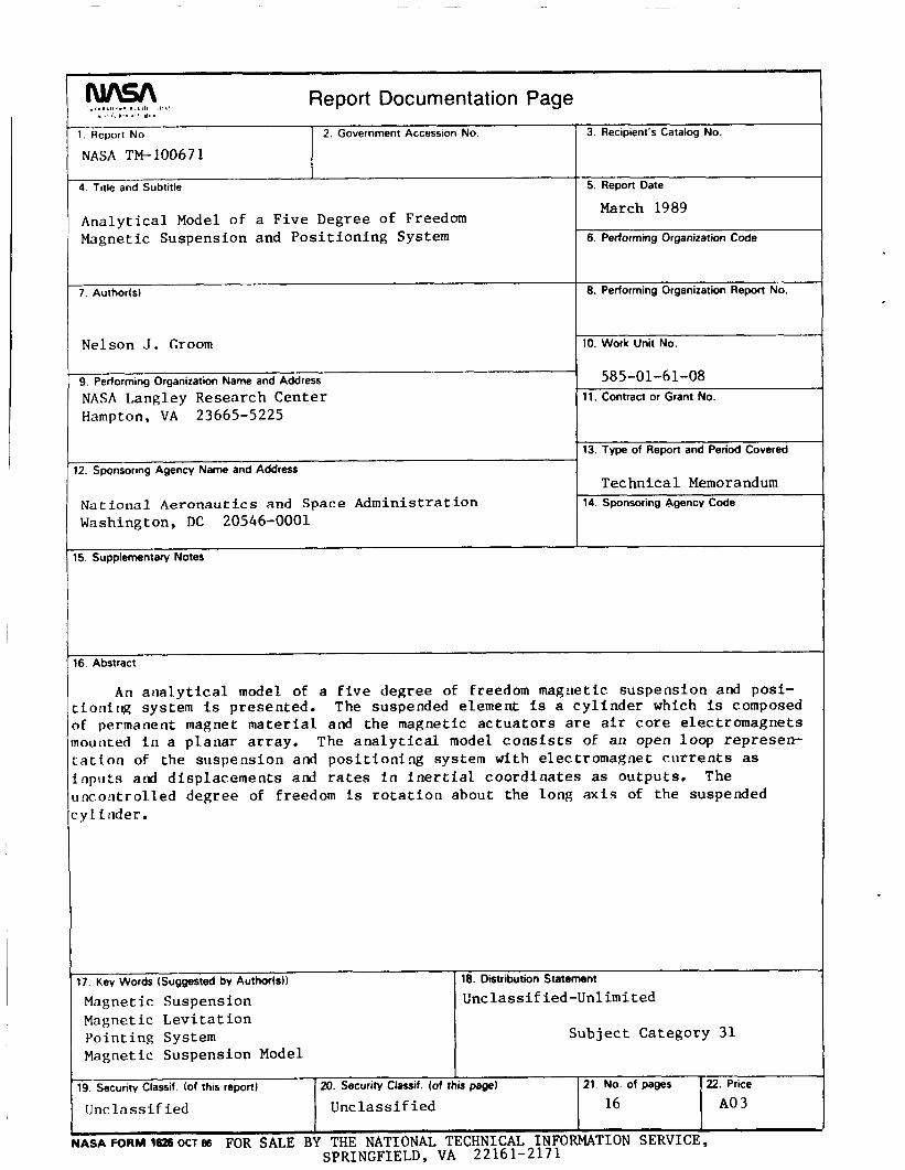
An analytical model of a five degree of freedom magnetic suspension and posi- tioning system is presented. The suspended element is a cylinder which is composed of permanent magnet material and the magnetic actuators are air core electromagnets mounted in a planar array. tion of the suspension and positioning system with electromagnet currents as inputs and displacements and rates in inertial coordinates as outputs. degree of freedom is rotation about the long axis of the suspended cylinder.
The analytical model consists of an open loop representa-
The uncontrolled
INTRODUCTION
This paper describes an analytical model of a five degree of freedom magnetic suspension and positioning system. composed of permanent magnet material and the magnetic actuators are air core elec- tromagnets mounted in a planar array. tion about the long axis of the suspended cylinder. mounted horizontally with the suspended element suspended above the array by repul- sive forces. suspension and positioning system with electromagnet currents as inputs and displace- ments and rates in inertial coordinates as outputs.
The suspended element is a cylinder which is
The uncontrolled degree of freedom is rota- The electromagnet array is
The analytical model consists of an open loop representation of the
EQUATIONS OF MOTION
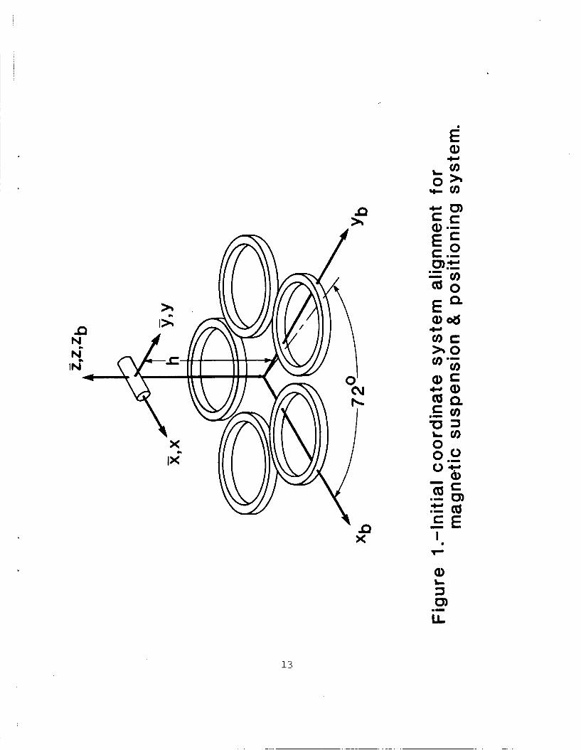
This section presents the equations of motion of the suspended element in gen- eral terms. The suspended element, or core, is a cylinder which is composed of per- manent magnet material. array of five electromagnets mounted in a circular arrangement. degrees of freedom are being controlled, this represents the minimum number of actu- ators. interacts with the fields of the suspension electromagnets to produce suspension and positioning forces and torques. shows the coordinate systems and initial alignment is shown in figure 1. A set of orthogonal 2 , 7 , and 5 body fixed axes defines the motion of the core with re- spect to inertial space. nal x, y, and z system fixed in inertial space. A set of orthogonal xb, yb, and Zb
to the Xb and yb axes respectively, and the z and Zb axes are coincident. The centers of the two axis systems are separated by the distance
The core is suspended, by repulsive forces, over a planar Since only five
The permanent magnet material provides the necessary magnetic field which
A schematic representation of this system which
The core axis system is initially aligned with an orthogo-
axes, also fixed in inertial space, define the location of the electromagnet I array with respect to the x, y, and z system. The x and y axes are parallel
h.
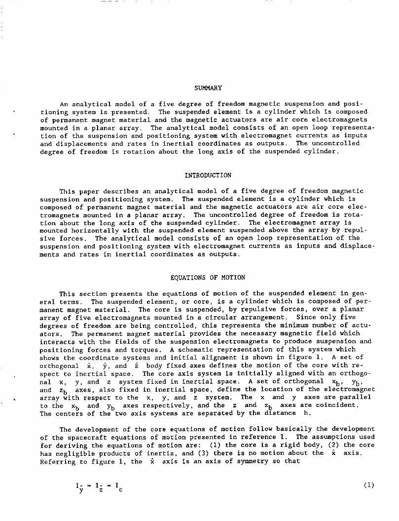
The development of the core equations of motion follow basically the development of the spacecraft equations of motion presented in reference 1. The assumptions used for deriving the equations of motion are: (1) the core is a rigid body, (2) the core has negligible products of inertia, and ( 3 ) there is no motion about the Referring to figure 1, the X axis is an axis of symmetry so that
X axis.
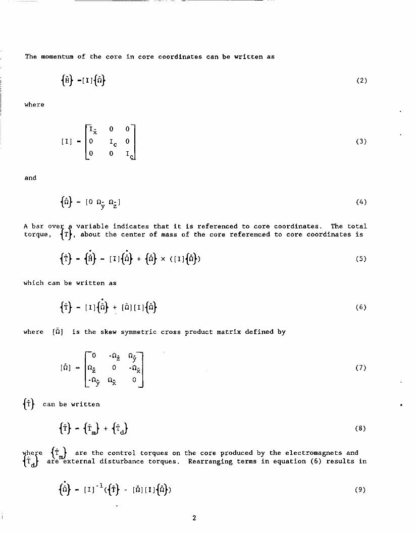
The momentum of the core in core coordinates can be written as
where
and
{h} = [O n- n - ] Y Z
variable indicates ~ o ~ ~ ~ e ~ V e { T ~ , about the center
that it f mass
which can be written as
is referenced to core coordinates. The total f the core referenced to core coordinates is
{?} can be written
e} - {T-J + fid)
( 4 )
where [ h ] is the skew symmetric cross product matrix defined by
whe e Gb are the control torques on the core produced by the electromagnets and fiJ are external disturbance torques. Rearranging terms in equation ( 6 ) results in
2
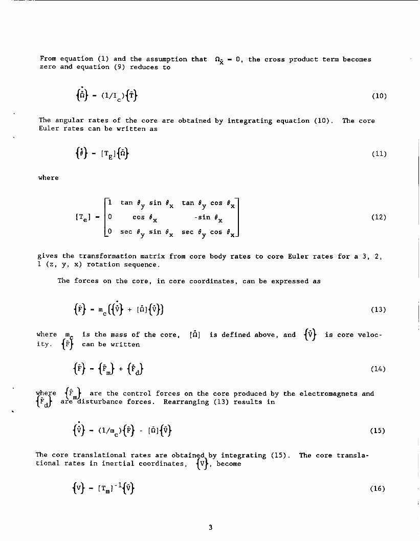
From equation (1) and the assumption that zero and equation (9) reduces to
n2 - 0, the cross product term becomes
The angular rates of the core are obtained by integrating equation (10). Euler rates can be written as
The core
where
1 tan 8 sin 8, tan 8 cos 8 , Y Y 1 ['el - 1 cos 8, -sin 8 ,
0 sec 8 sin BX sec 8 cos 8 , Y Y
gives the transformation matrix from core body rates to core Euler rates for a 3, 2, 1 ( 2 , y, x) rotation sequence.
The forces on the core, in core coordinates, can be expressed as
where ity. {FJ can be written
is the mass of the core, [h] is defined above, and {Q} is core veloc-
@} - {FJ + @J
are the control forces on the core produced by the electromagnets and $$ are disturbance forces. Rearranging (13) results in .
The core translational rates are obtained by integrating (15). tional rates in inertial coordinates,
The core transla- e}, become
3
where
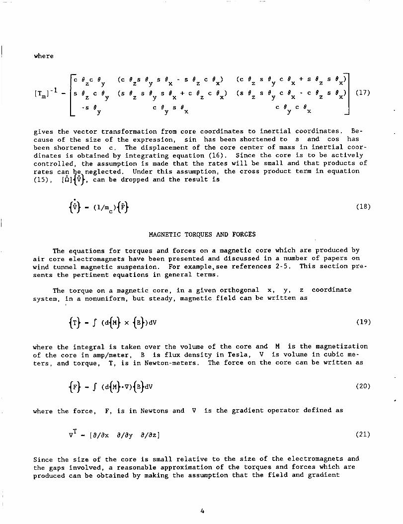
[ T m P =
- (c e z s By c ex + s e z s ex> - - s e z c ex)
+ c e z c ex> ( s e z s ey c ex - c e z s ex) (c e z s ex
e z (s e z ex
c e c e Z Y
ex ex - s e
Y
gives the vector transformation from core coordinates to inertial coordinates. cause of the size of the expression, sin has been shortened to s and cos has been shortened to c. The displacement of the core center of mass in inertial coor- dinates is obtained by integrating equation ( 1 6 ) . controlled, the assumption is made that the rates will be small and that products of rates can e neglected. Under this assumption, the cross product term in equation (15 ) , [6]ic}, can be dropped and the result is
Be-
Since the core is to be actively
MAGNETIC TORQUES AND FORCES
The equations for torques and forces on a magnetic core which are produced by air core electromagnets have been presented and discussed in a number of papers on wind tunnel magnetic suspension. sents the pertinent equations in general terms.
For example,see references 2-5. This section pre-
The torque on a magnetic core, in a given orthogonal x, y, z coordinate system, in a nonuniform, but steady, magnetic field can be written as
where the integral is taken over the volume of the core and of the core in amp/meter, B is flux density in Tesla, V is volume in cubic me- ters, and torque, T, is in Newton-meters. The force on the core can be written as
M is the magnetization
d
where the force, F , is in Newtons and V is the gradient operator defined as
Since the size of the core is small relative to the size of the electromagnets and the gaps involved, a reasonable approximation of the torques and forces which are produced can be obtained by making the assumption that the field and gradient
4
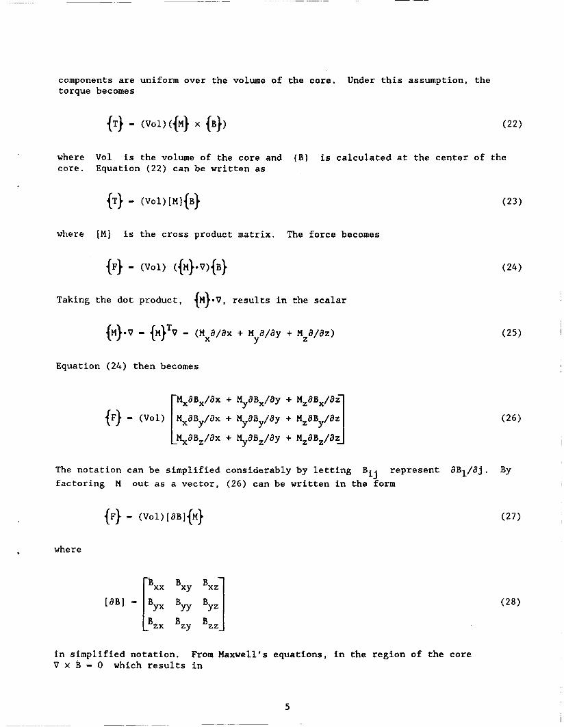
components are uniform over the volume of the core. Under this assumption, the torque becomes
where Vol is the volume of the core and (B) is calculated at the center of the core. Equation ( 2 2 ) can be written as
{T) - (W[MI+)
{F} - (Val) ({M}*V){B} where [MI is the cross product matrix. The force becomes
Taking the dot product, I.)*., results in the scalar {+v = {M}Tv = (Mxa/ax + M a/ay + Mza/az)
Y
Equation ( 2 4 ) then becomes
%aBx/ax + M,,aB,/ay + MzaBx/az IF) - (voi) saBy/aX + tt,,aBy/aY + MzaBy/aZ c saBz/ax + tt,,aB,/ay + M,aB,/aZ 1 2
The notation can be simplified considerably by letting Bij represent aBl/aj. By factoring M out as a vector, (26) can be written in the form
iF) = (voi)[a~i(M)
. where
Bxx Bxy Bxz
[aBl - [By. Byy 4.1 in simplified notation. V x B = 0 which results in
From Maxwell’s equations, in the region of the core
5
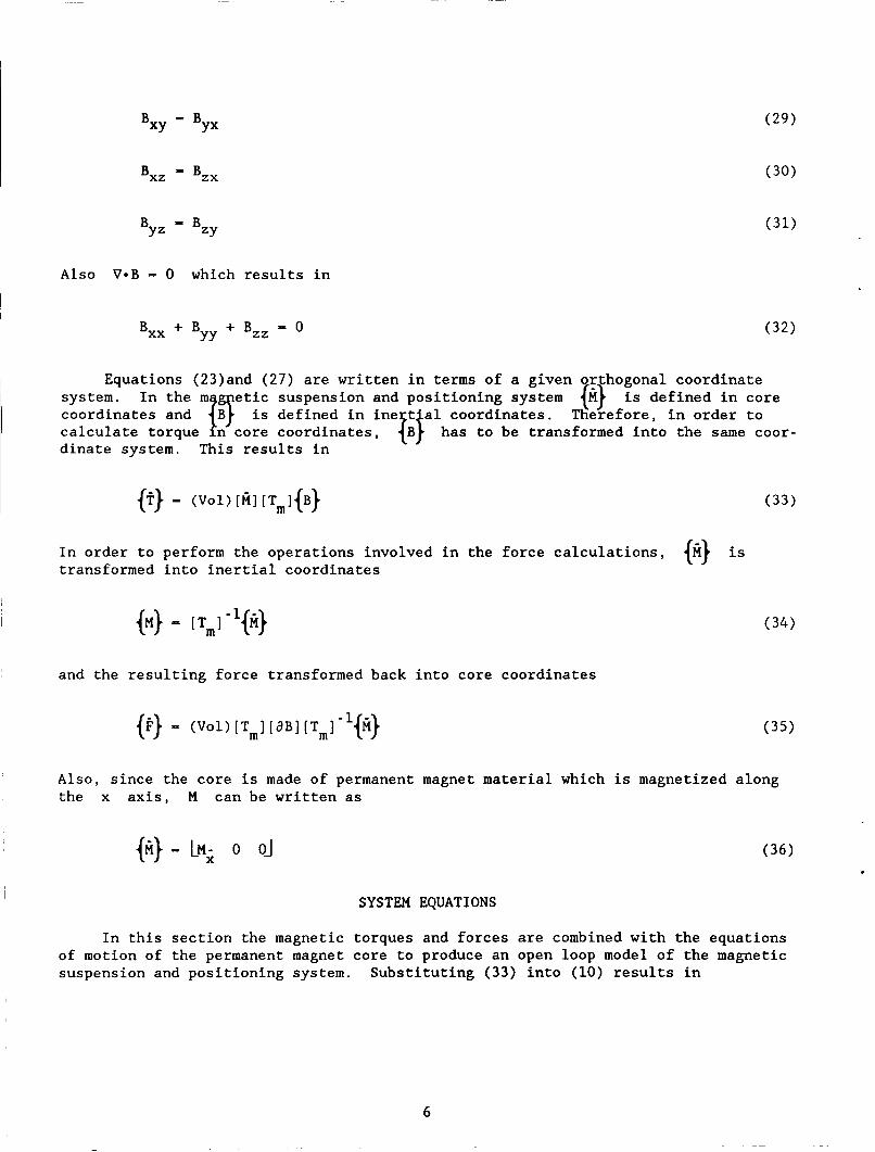
B - B XY YX
Bxz = Bzx
Byz - Bzy Also V-B = 0 which results in
(32) BXX + Byy + Bzz = O
Equations (23)and (27) are written in terms of a given orthogonal coordinate system. In the mjBT etic suspension and positioning system {M} is defined in core coordinates and is defined in ine t'al coordinates. Therefore, in order to calculate torque in core coordinates, fjB) has to be transformed into the same coor- dinate system. This results in
In order to perform the operations involved in the force calculations, transformed into inertial coordinates @} is
and the resulting force transformed back into core coordinates
Also, since the core is made of permanent magnet material which is magnetized along the x axis, M can be written as
{ii} - LM; o OJ
SYSTEM EQUATIONS
In this section the magnetic torques and forces are combined with the equations of motion of the permanent magnet core to produce an open loop model of the magnetic suspension and positioning system. Substituting ( 3 3 ) into (10) results in
6
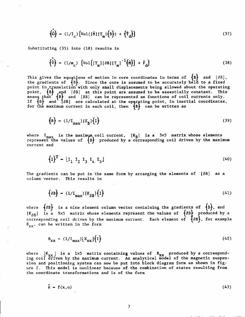
Substituting (35) into (18) results in
in core coordinates in terms of (B) and [aB], the core is assumed to be accurately held to a fixed
only small displacements being allowed about the operating at this point are assumed to be essentially constant. This
If aB] are calculated at the op r ting point, in inertial coordinates, and [aB] can be represented as functions of coil currents only.
each coil, then {BJ can be written as
where I,,, is the maxim coil current, [KB] is a 3x5 matrix whose elements represent the values of current and
produced by a corresponding coil driven by the maximum
The gradients can be put in the same form by arranging the elements of column vector. This results in
[dB] as a
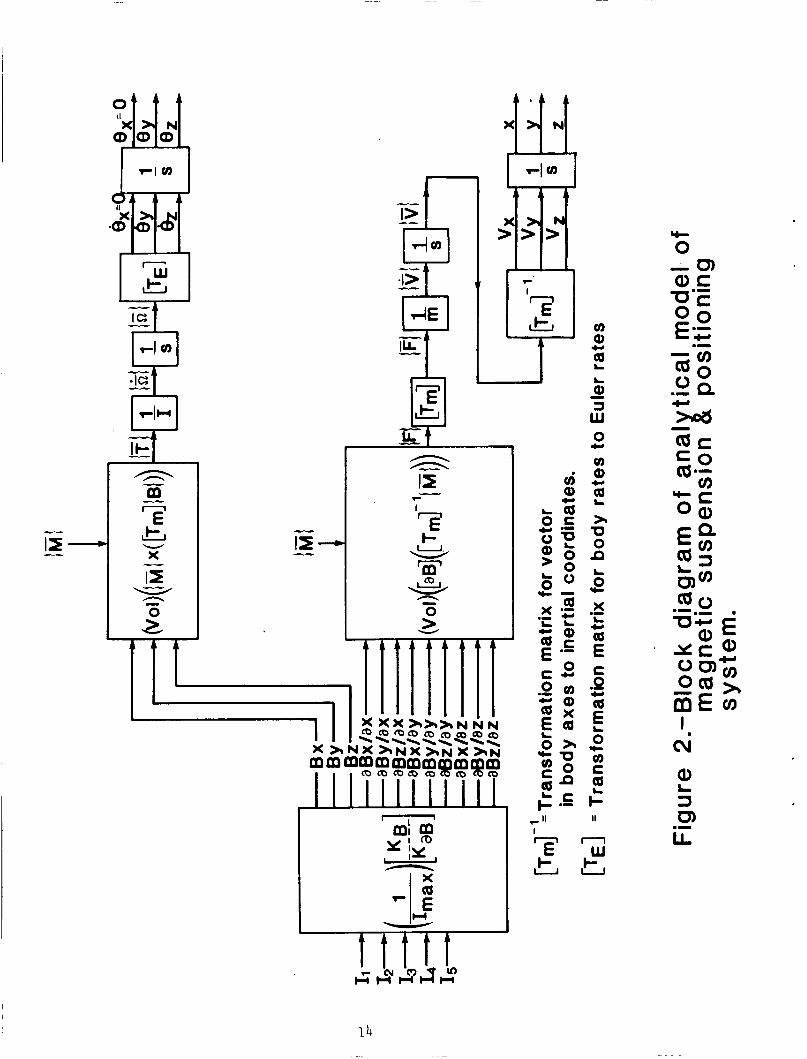
where {aB} is a nine element column vector containing the gradients of {B}, and [KaB] is a 9x5 matrix whose elements represent the values of {aB produced by a corresponding coil driven by the maximum current. Each element of {aB}, for example B,,, can be written in the form
where Lsxj is a 1x5 matrix containing values of Bxx produced by a correspond- ing coil driven by the maximum current. An analytical model of the magnetic suspen- sion and positioning system can now be put into block diagram form as shown in fig- ure 2. This model is nonlinear because of the combination of states resulting from the coordinate transformations and is of the form
0
x - f(x,u) (43)
7
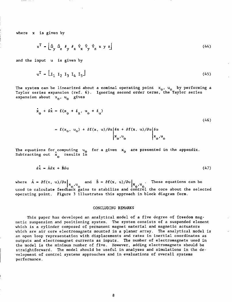
where x is given by
and the input u is given by
The system can be linearized about a nominal operating point Taylor series expansion (ref. 6 ) . Ignoring second order terms, the Taylor series expansion about xo, uo gives
xo, uo by performing a
4 + 6; = f(xo + bX, u0 + 6u) 0
= f(xo, uo) + df(x, u)/dx 6x + af(x, u>/au 6u
Ixo.uo l x o ~ ~ o
The equations forecomputing uo for a given xo are presented in the appendix. Subtracting out x results in
0
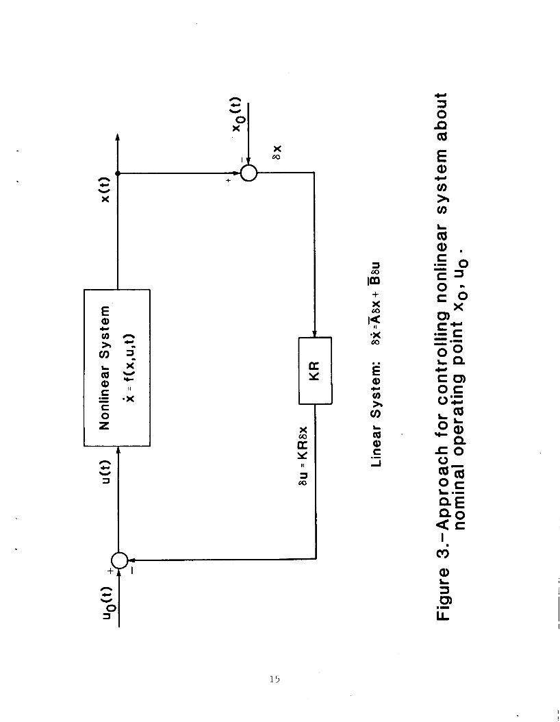
6; = A6x + h6u
- where A - af(x, u)/ax and B = af(x, u)/au
used to calculate feedback Rains to stabilize and I
1 osUo
( 4 7 )
. These equations can be
ontrol the core about the selected osuo X
operating point. Figure 3 illustrates this approach in block diagram form.
CONCLUDING REMARKS
This paper has developed an analytical model of a five degree of freedom mag- netic suspension and positioning system. which is a cylinder composed of permanent magnet material and magnetic actuators which are air core electromagnets mounted in a planar array. an open loop representation with displacements and rates in inertial coordinates as outputs and electromagnet currents as inputs. The number of electromagnets used in the model is the minimum number of five. However, adding electromagnets should be straightforward. The model should be useful in analyses and simulations in the de- velopment of control systems approaches and in evaluations of overall systems performance.
The system consists of a suspended element
The analytical model is
8

REFERENCES
1. Groom, Nelson J.: Fixed-Base and Two-Body Equations of Motion for an Annular Momentum Control Device (AMCD). NASA TM-78644, March 1978.
2 . Basmajian, V. V.; Copeland, A. B.; and Stephens, T.: Studies Related to the Design of a Magnetic Suspension and Balance System. February 1966.
NASA CR-66233,
3 . Stephens, Timothy: Design, Construction, and Evaluation of a Magnetic Suspension and Balance System for Wind Tunnels. NASA CR-66903, November 1969.
4 . Covert, Eugene E.; Finston, Morton; Vlajinac, Milan; and Stephens, Timothy: Magnetic Balance and Suspension Systems for Use in Wind Tunnels. Aerospace Sciences, Vol. 14. Pergamon Press, 1973.
Progress in
5. Britcher, Colin P.: Some Aspects of Wind Tunnel Magnetic Suspension Systems With Special Application at Large Scales. NASA CR-172154, September 1983.
6. Brogan, William L.: Modern Control Theory. Second ed. Prentice-Hall,Inc., 1985.
9
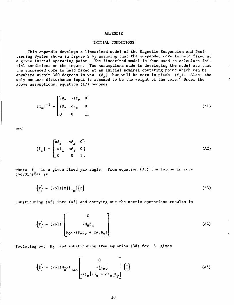
APPENDIX
INITIAL CONDITIONS
This appendix develops a linearized model of the Magnetic Suspension And Posi- tioning System shown in figure 2 by assuming that the suspended core is held fixed at a given initial operating point. The linearized model is then used to calculate ini- tial conditions on the inputs. The assumptions made in developing the model are that the suspended core is held fixed at an initial nominal operating point which can be anywhere within 360 degrees in yaw (e,) but will be zero in pitch (ey). Also, the only nonzero disturbance input is assumed to be the weight of the core. above assumptions, equation (17) becomes
Under the
and
where 6, is a given fixed yaw angle. From equation ( 3 3 ) the torque in core coordinates is
Substituting (A2) into (A3) and carrying out the matrix operations results in
I Factoring out Y;, and substituting from equation ( 3 8 ) for B gives
10
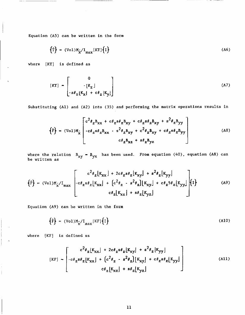
Equation (A5) can be written in the form
where [KT] is defined as
Substituting (Al) and (A2) into (35) and performing the matrix operations results in
@} - (Vo1)M;
where the relation be written as
Bxy - Byx has been used. From equation (40), equation (A8) can
Equation (A9) can be written in the form
where [KF] is defined as
11
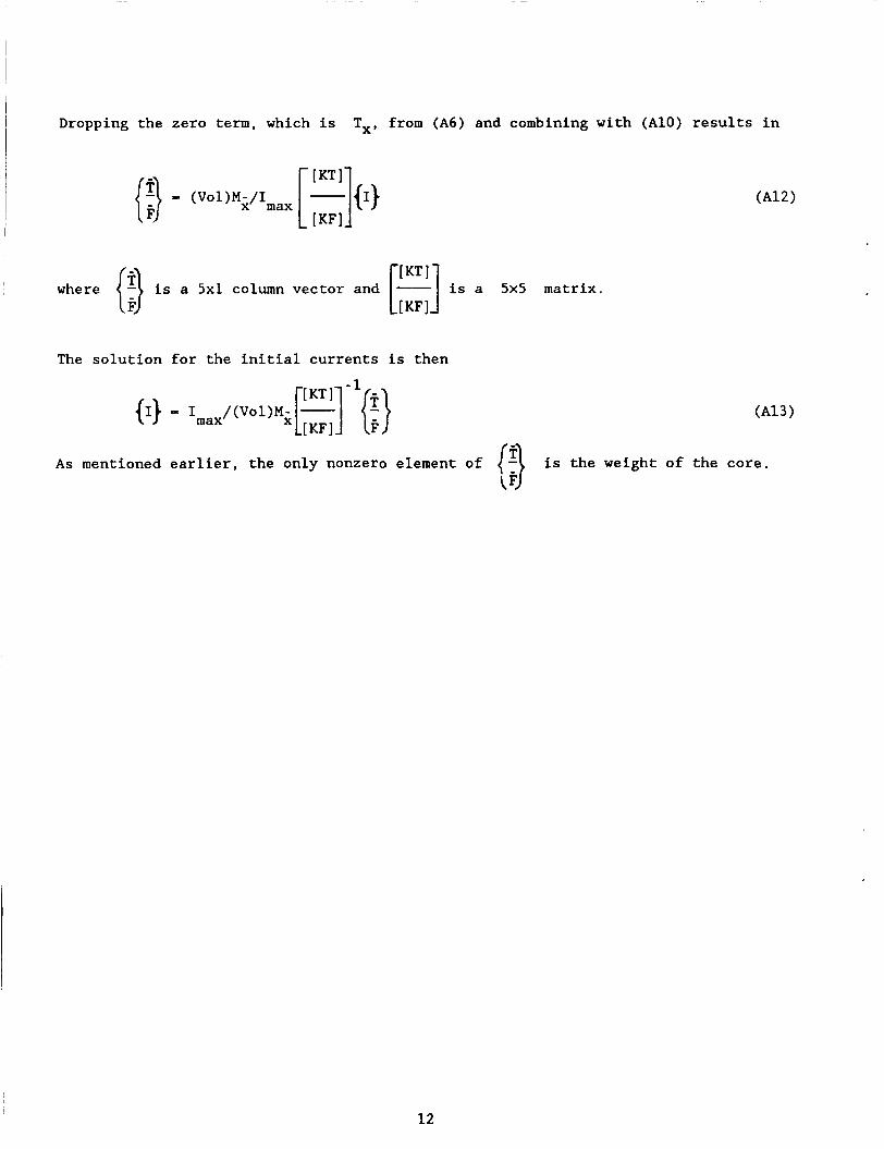
Dropping the zero term, which is T,, from (A6) and combining with (A10) results in
I
, [:::I is a 5x5 matrix. where {:} is a 5x1 column vector and -
The solution for the initial currents is then
As mentioned earlier, the only nonzero element of is the weight of the core.
12
€ a, c,
x
L O c .-
13
kl
I 1
I 1
I X
v) Q)
Q c,
L
0 ti 3 w 0
cn Q)
a >r U 0
w
c,
L
n 5 cc X
a
C
.I
L. c,
E
.P c,
E* L 0 v) C Q
cc
; II
n T w + I - u u
.I
14
3 M irn + x M
.x M
€ 0, c,
CI
C U I O C
'_,'..,,l.". 1 .1111 I . , '
I I I NASA FORM 1626 OCT 85 FOR SALE BY THE NATIONAL TECHNICAL INFORMATION SERVICE,
SPRINGFIELD, VA 22161-2171
Report Documentation Page 1 Report No 2. Government Accession No. 3. Recipient's Catalog No.
NASA TM- 10067 1 I 4. Title and Subtitle 5. Report Date
A n a l y t i c a l Model of a F i v e Degree of Freedom Magnet ic S u s p e n s i o n and P o s i t i o n i n g System
7. Authods)
Nelson J . Groom
March 1989
8. Performing Organization Report No.
10. Work Unit No.
9. Periorming Organization Name and Address
NASA Lang ley Research C e n t e r Hampton, VA 23665-5225
585-01-61-08 11. Contract or Grant No.
2. Sponsoring Agency Name and Address
National A e r o n a u t i c s and Space A d m i n i s t r a t i o n Washington , DC 20546-0001
6 Abstract
An a n a l y t i c a l model of a f i v e d e g r e e OE f reedom magne t i c s u s p e n s i o n and p o s i - i o n i r g sys tem is p r e s e n t e d . The suspended e l emen t is a c y l i n d e r which is composed
I € permanent magnet material and t h e magne t i c a c t u a t o r s are a i r core e l e c t r o m a g n e t s ounted i n a p l a n a r a r r a y . The a n a l y t i c a l model c o n s i s t s of a n open l o o p r e p r e s e n - a t i o n of t h e s u s p e n s i o n and p o s i t i o n i n g sys t em w i t h e l e c t r o m a g n e t c u r r e n t s as npi i t s and d i s p l a c e m e n t s and rates i n i n e r t i a l c o o r d i n a t e s as o u t p u t s . n c o n t r o l l e d d e g r e e of freedom is r o t a t i o n a b o u t t h e l o n g axis of t h e suspended yZ i nder.
The
13. Type of Report and Period Covered
T e c h n i c a l Memorandum 14. Sponsoring hgency Code
7. Key Words (Suggested by Authorts))
Magnet ic S u s p e n s i o n Magnet ic L e v i t a t i o n P o i n t i n g System Magnet ic S u s p e n s i o n Model
18. Distribution Statement
U n c l a s s i f i e d - U n l i m i t e d
S u b j e c t C a t e g o r y 31
9. Security Classif. (of this report)
l l n c l a s s i f i e d U n c l a s s i f i e d 20. Security Classif. (of this page) 21. No. of pages 22. Price
16 A0 3