Embed Size (px)
Citation preview
N A S A T E C H N I C A L M E M O R A N D U M
I
A 5E a c v) a 7
NASA TM X-67903
RECENT RADIAL TURBINE RESEARCH AT THE N A S A LEWIS RESEARCH CENTER
by Harold E. Rohlik and Milton G. Kofskey Lewis Research Center Cleveland, Ohio
t
TECHNICAL PAPER proposed for presentation at Gas Turbine Power and Fluids Engineering Divisions Conference sponsored by the American Society of Mechanical Engineers San Francisco, California, March 26-30, 1972
I'
https://ntrs.nasa.gov/search.jsp?R=19720005135 2018-05-19T20:06:06+00:00Z
RECENT R A D I X TURBINE RESEARCH AT THE NASA LEWIS RESElLRCH CENTER
by Harold E. Rohlik and Milton G. Kofskey
Lewis Research Center National Aeronautics and Space Administration
Cleveland, Ohio
ABSTRACT
.I The high efficiencies of mall radial turbines have led t o their application i n space power systems and numerous APU and shaft power engines. ment+ and analytical work associated with these sys- * 51 tef as included examination of blade-shroud clear-
Experi- w
'P ance, s blade loading, and exit diffuser design. Re- m sults indicate high efficiency over a wide range of specific speed and also insensitivity t o clearance and blade loading i n the radial part of the rotor. The exi t diffuser investigation indicated that a conventional conical outer w a l l may not provide the velocity variation consistent with minimum overall diffuser loss . A l i s t of recently published NASA radial turbine reports is included.
INTRODUCTION
The high efficiencies of small radial inflow turbines have resulted i n their use i n many APU' s, s m a l l turboshaft engines, and space power systems. The selection and development of components for specific applications has required harledge of Rey- nolds number effects, internal losses, blade-shroud clearance penalties, and other characteristics to assure adequate and safe operation. .
The Lewis Research Center of NASA began in 1962 t o investigate components designed under contract for Brayton cycle space parer systems. The studies in- cluded internal flow analyses as w e l l as experimental operation of compressors, turbines, alternators, and various combinations of these. The work i n radial turbines from 1962 t o 1967 was highlighted and sum- maxized i n Ref 1, a paper presented at the Second Intersociety Energy Conversion Engineering Conference i n August of 1967. Since that time work has continued i n the areas of blade-shroud clearance, blade loading, exi t diffusers, and a specific speed investigation with various s ta tor and rotor areas i n a single tur- bine. argon and the high precision instrumentation and pro- cedures described i n Ref. 2.
Experiments have been made with cold air and P
r, This paper includes the major results obtained in several experimental programs concluded since 1967 and others s t i l l i n progress. Detailed descriptions of the research hardware and the investigations may be found in the references l is ted.
TEST EQUIPMENT
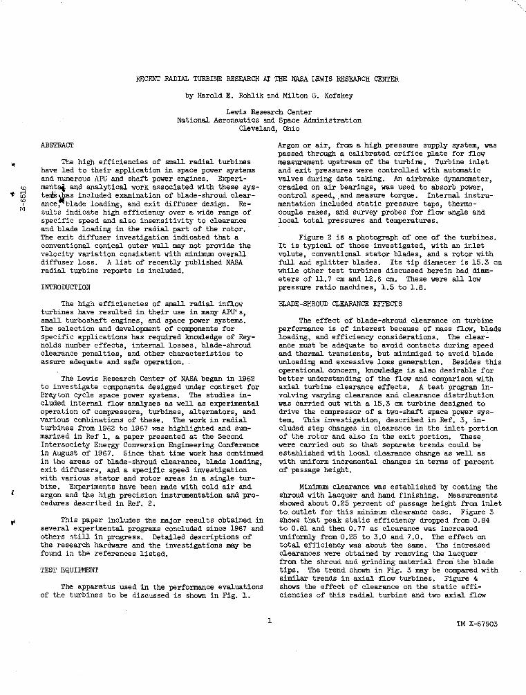
The apparatus used i n the performance evaluations of the turbines t o be discussed i s shown i n Fig. 1.
Argon or air, f r o m a high pressure supply system, was passed through a calibrated or i f ice plate for flow measurement upstream of the turbim. Turbine inlet and exit pressures were controlled with automatic valves during data taking. An airbrake dynamometer, cradled on a i r bearings, w a s used t o absorb parer, control speed,.and measure torque. Internal instru- mentation included s t a t i c pressure taps, thermo- couple rakes, and survey probes for flow angle and local to ta l pressures and temperatures.
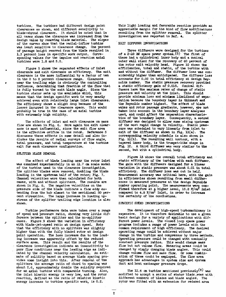
Figure 2 is a photograph of one of the turbines. It i s typical of those investigated, with an inlet volute, conventional stator blades, and a rotor with f i l l and sp l i t t e r blades. Its t i p diameter i s 15.3 cm while other tes t turbines discussed herein had diam- e ters of ll.7 cm and 12.6 a. These were all low pressure ra t io machines, 1.5 t o 1.8.
BLADE-SHROUD CLEARANCE EFFECTS
The effect of blade-shroud clearance on turbine performance is of interest because of mass flow, blade loading, and efficiency considerations. The clear- ance m u s t be adequate to avoid contacts during speed and thermal transients, but minimized t o avoid blade unloading and excessive loss generation. operational concern, howledge is also desirable f o r bet ter understanding of the f l o w and comparison with axial turbine clearance effects. A t e s t program in- volving varying clearance and clearance distribution was carried out w i t h a 15.3 cm turbine designed t o drive the compressor of a two-shaft space power s y s - tem. This investigation, described i n Ref. 3, in- cluded step changes i n clearance i n the in le t portion of the rotor and also i n the exi t portion. These were carried out so that separate trends could be established with local clearance change as w e l l as with uniform incremental changes i n terms of percent of passage height.
Besides t h i s
Minimun clearance was established by coating the Measurements shroud with lacquer and hand finishing.
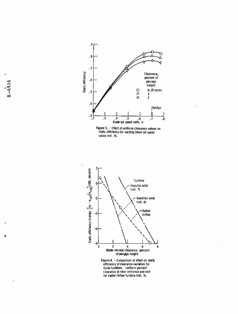
shaved about 0.25 percent of passage height f r o m in le t t o outlet for th i s minimum clearance case. shows that peak s t a t i c efficiency dropped from 0.84 t o 0.81 and then 0.77 as clearance was increased uniformly from 0.25 t o 3.0 and 7.0. The effect on t o t a l efficiency was about the same. The increased clearances were obtained by removing the lacquer from the shroud and grinding material from the blade t ips . The trend shown i n Fig. 3 may be compared with similar trends i n axial flow turbines. shows the effect of clearance on the s ta t ic e f f i - ciencies of th i s radial turbine and two axial f l o w
Figure 3
Figure 4
1 TM X-67903
turbines. clearances as s h m , and different sensit ivity t o blade-shroud clearance. It should be noted that in a U cases s h m the clearance was increased from the design value by rempving blade material. The slopes of the curves show that the radial-inflow turbine was least sensitive t o clearance change. One percent of passage height removed from the blade resulted i n 1.3 percent loss in specific work output. sponding values for the impulse and reaction axial turbines were 1.8 and 3.0.
The turbines had different design point
C o r r e -
Figure 5 show the separated effects of i n l e t .I
clearance and exi t clearance on efficiency. clearance is the more influential by a factor of ten in the 0 t o 8 percent clearance range. near the t ra i l ing edge is obviously the controlling influence, determining that fraction of the flow that i s fully turned to the exit blade w e . Since the turbine stator sets up the available whirl, th i s means that the design specific work i s very nearly achieved even with relatively large i n l e t clearances. The efficiency s h m a slight drop because of the losses incurred in the clearance space. probably be true in the case of an axial turbine with extremely hi& solidity.
flaw are s h m i n Fig. 6. ance i s most influential, since the exit f l o w area i s the effective orifice in the rot&. Reference 3 discusses these effects in sane detai l and also in- cludes the results of radial surveys of f l a w angle, t o t a l pressure, and to ta l temperature a t the turbine exit for each clearance configuration.
SKITTER BLAE RFmvfi
The exit ,
Clearance
This would
The effects of inlet and exit clearance on mas6 Here again the exi t clear-
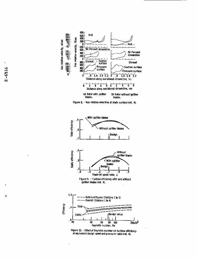
The effect of blade loading near the rotor inlet was examined e x p e r h n t d l y in an U.7 m scale model of the turbine used in the clearance investigation. The sp l i t t e r blades were removed, doubling the blade loading i n the upstream half of the rotor; Fig. 7. Channel velocit ies were then calc-ted for both cases, with and Without spl i t ters . The results are shown in Fig. 8. The negative velocities on the pressure side of the blade indicate a f low eddy ex- tending from the hub almost t o the meridional 50 per- cent streamline. The large increase i n loading up- stream of the sp l i t t e r t ra i l ing edge location i s also s h m .
J Turbine performance data were taken over a range of speed and pressure ratio, showing very l i t t l e dif- ference between the sp l i t t e r and the no-splitter cases. Figure 9 shows the variation i n efficiency with blade-jet-speed rat io a t design speed. Note that the efficiency with no sp l i t t e rs was slightly higher than with the ful ly bladed rotor a t design point operation. ing increase w a s apparently offset by the reduced surface area. This result and the results of the clearance investigation indicate an insensitivity t o poor flow conditions near the leading edge as indi- cated by the channel velocity calculation. An es t i - mate o f solidity based on average blade spacing pro- vides some insight into this . After removal of the sp l i t t e rs the average rat io of chord t o spacing was about 2.6, approximately double the solidity required for an axia l turbine with comparable turning. Also, the in le t kinetic energy i s very low, and the rotor reaction, defined as the ra t io of relative kinetic energy increase to turbine specific work, i s 0.2.
2
The loss increase due to the load-
This l ight loading and favorable reaction providh an appreciable margin for the kind of f l o w modifications resulting fram the sp l i t t e r removal. investigation was reported i n Ref. 4.
EXIT DIFFUSER INVESTIGATIONS
The sp l i t t e r
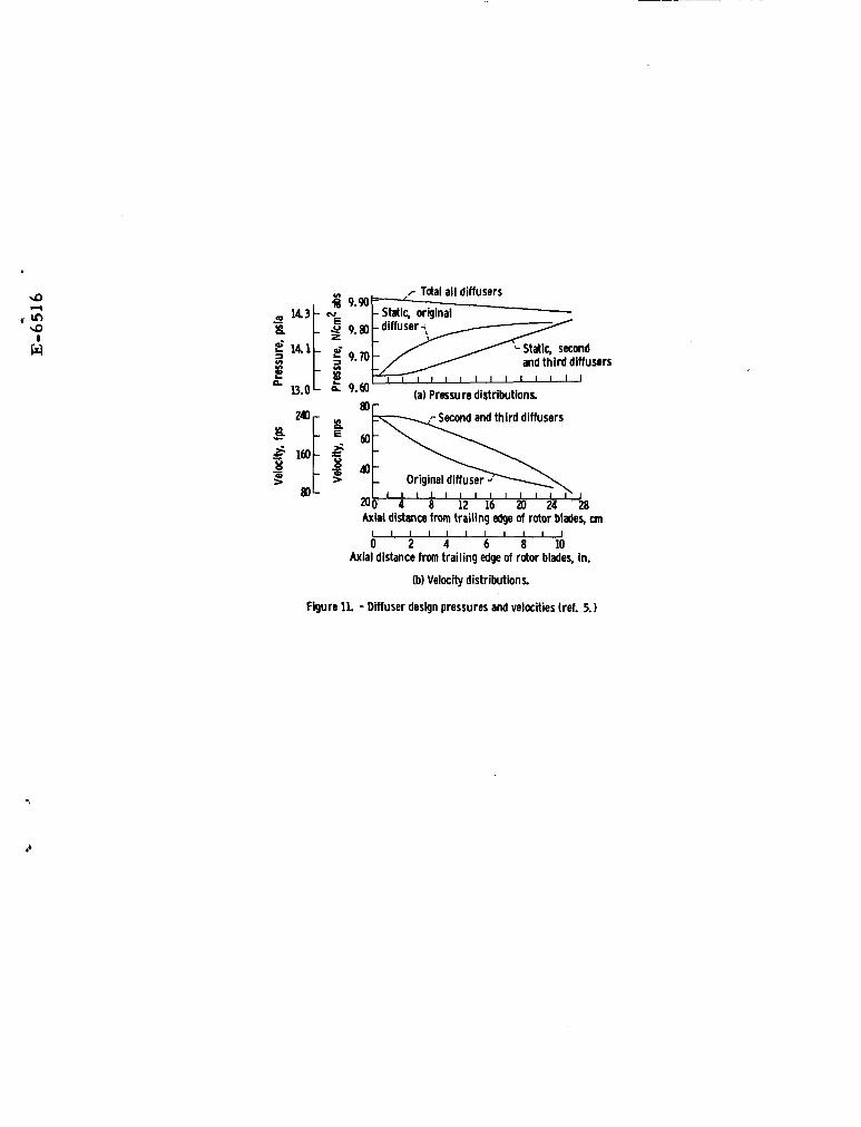
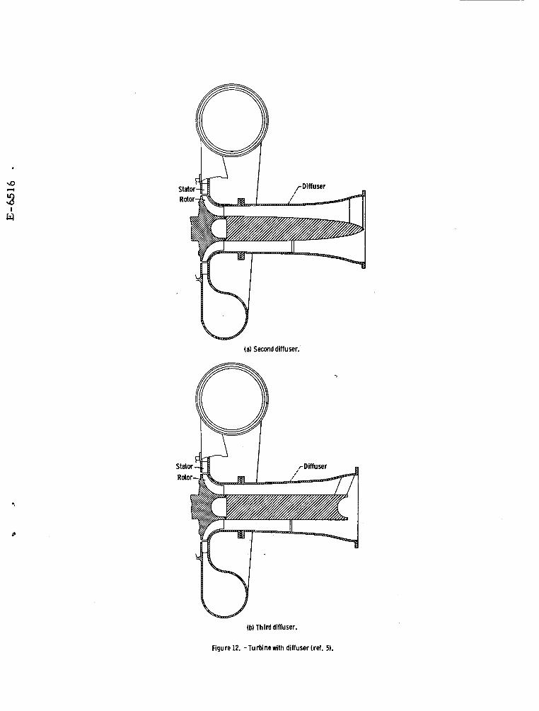
Three diffueers were designed for the turbines of 8 2-10 H space pawer system.(5) these had a cylindrical inner body and a conical outer wall sized for the recovery of 60 percent of the rotor ex i t velocity he&l. Figure 10 shows the efficiencies, t o t a l and stat ic , of the turbine with and without the diffuser. The diffbser loss was con- siderably higher than anticipated. The diffuser loss accounts for 0.02 i n t o t a l efficiency a t design Rey- nolds number. The s ta t ic pressure recovery provided a s ta t ic efficiency gain of 0.015. fusers have the maxjnnnn rates of change of s t a t i c pressure and velocity a t the inlet . provide minimum loss and m i n i m u likelihood of sepa- ration because the boundary layer is thinnest and the Reynolds number highest. The effect of blade wakes and rotor passage gradients, however, &e not taken into account in the boundary layer analyses used, and could r p e c t the separation characteris- t i c s of the b0uiku-y layer. Consequently, a second diffuser was designed to allow some mixing upstream of the most rapid change in velocity. Stat ic pres- sure was scheduled t o vary linearly f r o m in le t t o exit of the diff'user as shown in Flg. l l ( a ) . The corresponding velocity schedule is a leo shown i n Fig. l l ( b ) . The resulting wall contour, with a tapered inner body, i s the trumpet-lih shape i n fig. 12. A t h M diffuser was very similar t o the second, but w i t h a cylindrical body.
me first of
Conical dif-
This should
Figure U shows the overall t o t a l efficiency and s t a t i c efficiency of the turbine with each diffuser. The gain with the diffusers designed for a linear variation in s t a t i c pressure was about 0.01 in t o t a l efficiency. Measurement accuracy was c r i t i c a l here, with the gain i n efficiencies Shawn resulting f r o m small differ- ences in measured pressures a t the design R e y n o l d s number operating point. firned therefore at a higher level, 13.8 N/m2 in le t campared to 4.8 N/& inlet, in order t o increase the certainty of the conclusions.
SPECIFIC SPEED INVESTIGATIONS
The diffbser loss was cut in half.
The measurements were con-
The development of high-speed turbomachinery is expensive. It is therefore desirable t o use a given basic design for a variety of applications with dif- ferent power levels. The closed loop space power program includes a raage of power levels with the common requirement of high efficiency. operating range could be achieved without major change in the turbine and compressor by three methods. Operating pressure could be changed with ncmindy constant pressure ratios. This would change mass flow but not volume flow. Metering areas could be changed by s h p l y changing blade angles. change volume f low and mass f low. Or sane combin- ation of these could be employed. approach has advantages in system size and system duct and heat exchanger pressure drops.
The desired
This could
The flow area
The 12.6 cm turbine mentioned previously(6) was modified to accept a series of s ta tor blade.mws with different numbers of blades and blade W e s . rotor was f i t t e d with an extension for reduced area
The
operation and w a s also cut back for increased area operation. vary stator throat area frcun 20 to 144 percent of the design throat area and rotor throat area from 53 to 137 percent. Figure 14 shows the rotor as designed, with the reducing extension, and cut back. Details on the geometry, t e s t results, and interne3 velocity calculations are described in Ref. 7.
These modifications were employed to
Performance was then experimentally determined
Figure 15 shows the envelopes of the design- for thirteen combinations of stator area and rotor area. speed efficiency curves obtained with each rotor configuration. combination was varied simply by varying overell pressure ra t io a t design speed.
: Specific speed for each stator-rotor
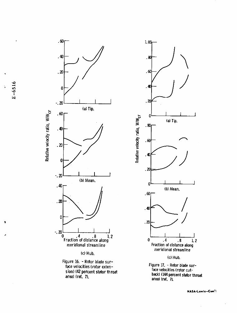
Note that t o t a l efficiencies over 0.90 were measured for specific speeds between 0.37 and 0.80. A t the high and low ends of the high efficiency range of specific speed, the ra t io of s ta tor throat area t o rotor throat area was near the design ratio. Efficiency vias lower for area rat ios not near the design ratio. sign area were 42-53 (stator-rotor) percent and 144- 137 percent. reaction. Velocities i n the f l o w passages upstream of the throats, however, deviated considerably fram the design internal velocities because of the dif- ferent volume flows. The high volume f l o w was more than four times the l o w volume flow. Blade surface velocities for each stator-rotor canbination were calculated and included i n the reference. The low f l o w case solution, Fig. 16, indicated a large pres- sure surface f l o w eddy extending frau the leading edge halfway through the sp l i t t e r blades on the shroud and w e l l beyond the sp l i t t e r blades along the hub. Also, velocities near the in le t are quite low. An examination of internal losses, based on f l o w measurements showed that rotor losses increased by about 0.006 i n t o t a l efficiency i n reducing the f l o w areas f r o m design values t o the 42 t o 53 percent combination. to 0.895 with the loss increase ocdurring largely i n the stator.
The best combination in terms of de-
These provided just about design s ta tor
OveraJl efficiency decreased frau 0.930
Figure 17 shows the internal f l o w velocities calculated for the high flow (144-137 percent) case. The velocity levels upstream of the throat are con- siderably higher than i n the low flow case, indi- cating higher blade loading, lower reaction, and all velocities w e l l above zero, i.e. no f l o w eddy. Total efficiency was 0.92, indicating very slight in- creases in s ta tor and rotor viscous losses Over those of the design area configuration.
This investigation indicated again that radial turbines are relat ively insensitive to unfavorable f l o w conditions in the upstream part of the rotor passages.
CONCLUDIliG FQWVXS
The radial turbine effort began a t the Lewis Research Center as technical support for the Brayton cycle space power program. The intent was t o learn more about the performance characteristics i n order t o increase efficiency and to properly assess losses where comprdses might result frm mechanical and thermal considerations or any other operational re- quirements. The analytical techniques in flow analy- sis, off design performance estimation, etc. , and ex- perimental information have been helpful i n system
studies and advanced component designs.
The radial turbine program i s continuing in sup- port of both the Brayton cycle space power program and advanced small airbreathing engine programs in- volving such applications as helicopter, A N , vehic- ular, etc. vanced turbine suitable for the 2-10 kW single-shaft system. The design employed lonowledge obtained i n the radial turbine studies a8 well as some axial turbine investigations. The turbine has stators with converging endwalls for low-velocity turning, no splitters, and tandem rotor blades. i s the study of the effect of rotor t i p cutback on radial turbine performance.
One effor t i n process involves an ad-
A second effor t
Other studies under way are directed a t problems associated with high temperature cooled radial tur- bines. One such design is currently under way that includes a l o w blade number, no spl i t ters , and very thick leading edges at reduced diameter t o accommo- date cooling and res i s t erosion damage. Another area of effor t is that of radial turbine erosion and m?th- ods for i t s reduction. at achieving the re l iab i l i ty and structural integ- r i t y required f a these small turbines while main- taining the high efficiency levels associated with more ccmventional radial turbines.
REFERENCES
These programs are directed
1. Rohlik, H. E., Kofskey, M. G., and Katsanis, T., ''Sunrmary of NASA Radial Turbine Research Related t o Brayton Cycle Space Pbwer Systems," TM X-52298, 1967, NASA, Cleveland, Ohio.
:
2. Futral, 6. M., Kofskey, M. G., and Rohlik, H. E., "Instrumentation Used to Define Performance of S m a l l Size, Low Power Gas Turbines," TM X-52522, NASA, Cleveland, Ohio.
3. F'utral, S. M. Jr., and Holeski, D. E., "Ex- perimental Results of V a r y i n g the Blade-Shroud Clearance i n a 6.02-Inch R a d i a l Inflow Turbine," TN D-5513, 1970, NASA, Cleveland, Ohio.
4. Fut rd , S. M. Jr., and Wasserbauer, C. A., "Experimental Performance Evaluation of a 4.59-Inch Radial-Inflow Turbine With and Without Spl i t ter Elades," TN D-7015, 1970, NASA, Cleveland, Chio.
5. Nusbaum, W. J., and Kofskey, M. G., "Radial- I n f l o w Turbine Brformance with E x i t Diffusers De- signed for Linear Stat ic Pressure Variation," TM X- 2357, 1971, NASA, Cleveland, Ohio.
6. Nusbaum, 8. J. , and Kofskey, M. G., "Cold Performance Evaluation of a 4.97-Inch Radial-Inflow Turbine Designed for a Single-Shaft Brayton Cycle Space-Paver System," TN D-5090, NASA, Cleveland, Ohio,
7. Kofskey, M. G., and Nusbaum, W. J., "Effects of Specific Speed on the Experimental Performance of a Radial-Inflow Turbine," Proposed Technical Note.
3
I .
-Turbine working f luid from high pres- sure gas supply
r A i r from h igh pres- I sure supply system
CD-9968-01
Figure 1. - Experimental equipment. (ref 2)
C-72323 Figure 2. - T u r b i n e rotor and scroll (ref. 3).
0 0.25hnin)
- 3 .4 .5 .6 .7 .8 Blade-jet speed ratio, v
Figure 3. - Effect of uniform clearance values on static efficiency for varying blade-jet speed ratios (ref. 3).
0 2 4 6 8 Blade-shroud clearance, percent
of pasyge height
Figure 4. - Comparison of effect on static efficiency of clearance variation for three turbines, Uniform percent clearance at rotor entrance and exit for radial-inflow turb ine (ref. 3).
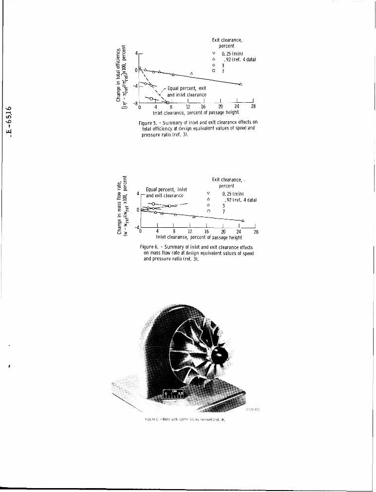
Exit clearance, percent
V 0.25Imin) A .92 (ref. 4 datal
-4 -\ ,r Equal percent, exit
-8 n 4 8 12 16 20 24 28
0 3 0 7
\ I
Y and in let clearance I I I I I
n 4 8 12 16 20 24 28 -8
Inlet clearance, percent of passage height
Figure 5. - Summary of inlet and exit clearance effects on total efficiency at design equivalent values of speed and pressure ratio (ref. 31.
c E Exit clearance. . percent
Equal percent, in let r a n d exit clearance V 0.25(minl
A .92 (ref. 4 datal
I In let clearance, percent of passage height
Figure 6. - Summary of in let and exit clearance effects on mass flow rate at design equivalent values of speed and pressure ratio (ref. 3).
-70-8lC
Figure 7. - Rotor with split+Pr b!ades removed (ref. 41.
.- L ti; e v) m 0
Shroud ,r !,U:ig surface m u
0 .8 16 24 3.2
r
u %-Percent 13 ?;line
Shroud
0 .8 L6 2.4 3.2 Distance along meridional streamline, in. - I I " " " 1
0 2 4 6 8 0 2 4 6 8 Distance along meridional streamline, cm
(a) Rotor with splitter (b) Rotor without splitter blades. blades.
Figure 8. - Gas relative velocities at blade surface (ref. 4).
With splitter blades
a, V .-
Without splitter blades F .a - z Design .7 I I I 111 splitter blades
L With splitter blades .-
2 Design . 7 .4 .5 .6 .7 .8 .9
Blade-jet speed ratio, v
111 splitter blades
L With splitter blades .-
2 Design . 7 .4 .5 .6 .7 .8 .9
Blade-jet speed ratio, v Figure 9. -Turbine efficiency with and without
splitter blades (ref. 4).
Before diffusion (Stations 1 to 3) Lor = Overall (Stations 1 to 4)
______- ------- -------
I Design value I I I I I l l 1 1
40 60 80 100 Reynolds number, Re
Figure 10. -Effect of Reynolds number on turbine efficiency at equivalent design speed and pressure ratio (ref. 6).
143
t
,r Total all diffusers 9.90
Static orhinal
and third diffusers
(a) Pressure distributions. 9. bo
> m
P b 8 2 Original diffuser
I I I \
ab' 4 Axial distance from trailing edge of rotor blades, cm
8 I i2' I6 I h I h ' h I I I I I I I I I I I 0 2 4 6 8 1 0
Axial distance from trailing edge of rotor blades, in.
(b) Velocity distributions.
Figure 1L - Diffuser design pressures and velocities (ref. 5.)
d
w
(a) Second diffuser.
(b) Third diffuser.
Figure 12. - TurMnewith diffuser (ref. 5).

Diffuser - Original Second Third
-- --- c LO
Total efficiency
Design value
B - E .-
E leer Static efficiency
- 9 t - = IDesign value ._ .60 .64 .68 .72 .7b .80 .84
Blade-jet speed ratio, v
Figure U. - Variation of turbine efficiency with blade- jet speed ratio at equivalent design speed for the three diffusers.
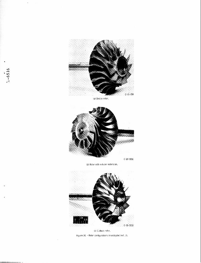
(a) Design rotor.
C-69-1816
(b) Rotor w i t h exducer extension.
C-70-3533
(cl Cutback rotor.
F igure 14. - Rotor configurations investigated (ref. 7).
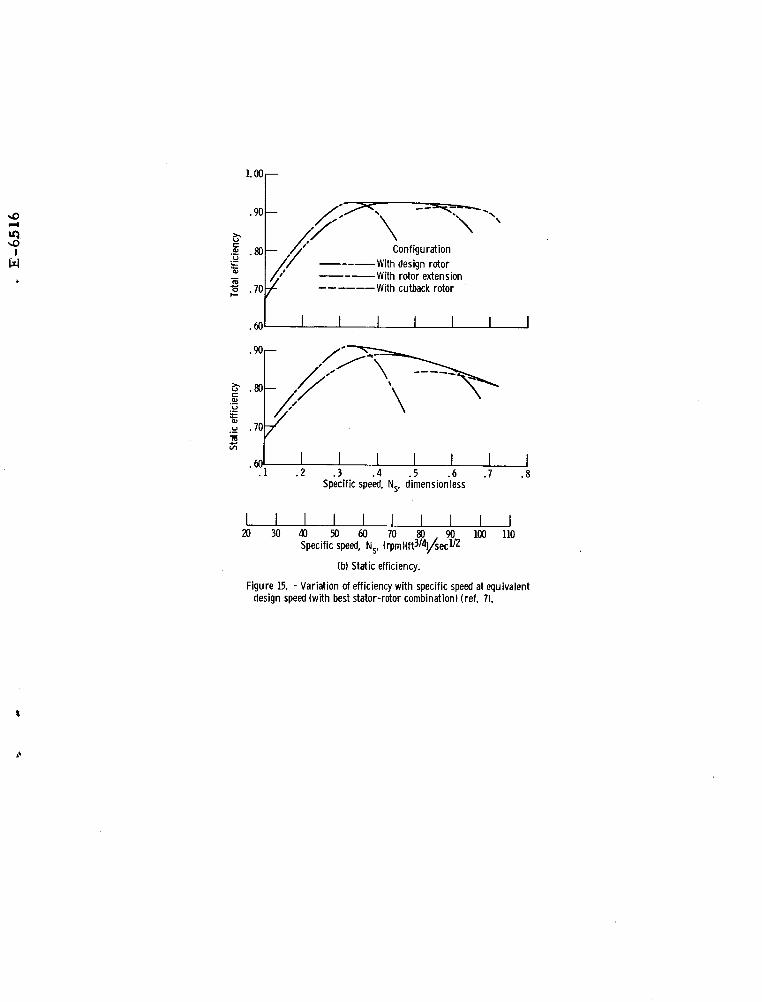
.90 . Configuration
With design rotor With rotor extension With cutback rotor
--_- --- al
---___
. 1 . 2 . 3 . 4 . 5 . 6 .7 .8 Specific speed, N,, dimensionless
.@I-
$
9
' I n 9
4
c;
::I 0 J -. 20 u
(a) TiD.
.20 :b 0
-. 20 u (b) Mean.
-. 20 0 . 4 . 8 1.2
Fraction of distance alona ., meridional streamline
(c) Hub.
Figure 16. - Rotor blade sur- face velocities (rotor exten- sion) (42 percent stator throat area) (ref. 7).
0
.@I- (b) Mean.
- . 8 1.2 0 . 4
Fraction of distance along meridional stream I ine
(c) Hub.
Figure 17. - Rotor blade sur- face velocities (rotor cut- back) (144 percent stator throat area) (ref. 7).