Embed Size (px)
Citation preview
oIr_
<O
p
L
RESEARCH MEMORANDUM _
AN ANALYSIS OF AVAILABLE DATA ON EFFECTS OF WING-
FUSELAGE-TAIL AND WI2.,IG-I_CELT._. IN'I'Et_Et_INCE
ON T_IE DISTRIBUTION OF THE AIR LOAD
- /
AMONG COMPONENTS OF AIRPLANES *
Bertram C. Wollner
Langley Aeronautical Laboratory
Langley Air Force Base, Va.
J
NATIONAL ADVISORY COMMITT££FOR AERONAUTICS
ii
.... ,L
,h-"
WASHI NGTON
April ii,1949. ii

7] 1 7
,+c++,,o.+.+.o UlC,ldCe Fi[DNATIONAL ADVISORY COMMITTEE FOR AEI_OKP..T.T_IOS
AN ANALYSIS OF AVAILABLE DATA ON EFFECTS OF
FUSELAGE-TAIL AND WIN_C_ INI_E
ON THE DISTRIBUTION oF THE AIR LOAD
AMONG COMPOI_S OF AIR_
By Bertram C. Wollner
SUMMARY
O
em
=o
J
Available information on the effects of wlng--fuselage-tall and
wing--nacelle interference on the distribution of the air load among
components of airplanes is analyzed. The effects of wing and nacelle
incidence, horizontal and vertical position of wing and nacelle,
fuselage shape, wing section and filleting are consldsred.
Where sufficient data were unavailable to determine the distribu-
tion of the air load, the change in lift caused by interference between
wing and fuselage was found. This increment is affected to the greatest
extent by vertical wing position.
%
0
-I
INTRODUCTION
At the design points on the V-n diagram where the magnitude of the
over-all load is given by specification, it is commonly assumed that thewing either carries all the load or the fuselage carries the portion that
would normally be carried by the intercepted wing area. These assump-
tions result in conservative designs for the wing if the loads carried bythe fuselage and tall act in the same direction as that on the wing and
in an unconservative design if they act in an opposite direction.
Along experimental lines there are very little data in the litera-
ture that can be used to determine the division of loads among the
airplane components. So far as is known, the only tests in whichdirectly useable data on the division of load are given are the flighttests described in references 1 and 2. Some indirect tests have been
made, however, which apply to the general problem of the division of
load. These are the tests performed in connection with the wing-fuselage
interference program previously reported in references 3 and 4.
2 NACA RM No. LgBIO
Along theoretical lines there are several methods that may be usedto find the distribution of the air load among airplane components.
References _ to 7 are typical of these mathematical methods which are
limited in use to special simplified cases.
The purpose of the present paper is to Summarize the available data
on the effects of wlng-fuselage-tail and wing-nacelle interference on
the distribution of the air load among aircraft components. The effects
of wing and nacelle incidence, horizontal and vertical position of wing
and nacelle, fuselage shape, wing section and filleting, are considered.
Some discussion is also given of the effects of center-of-gravity position.
BYMBOI_
CL
q
S
M
C_
X
zN
In the analysis of the data, the following symbols have been adopted:
lift coefficient (Lift/qS)
dyuamic pressure, pounds per square foot
gross wing area, square feet
Mach number
angle of attack of wing chord line at model center line,
degrees
longitudinal displacement of airfoil quarter-chord axisfrom fuselage quarter-chord point in terms of wingmean chord
longitudinal displacemsnt of nacelle quarter-chord point
from wing quarter-chord axis in terms of wing meanchord
vertical displacement of airfoil quarter-chord axis from
fuselage axis in terms of wing mean chord
vertical displacement of nacelle axis from airfoil
quarter-chord axis in terms of wing mean chord
wing angle of incidence with respect to fuselage axis,
degrees
angle of incidence of nacelle axis wlth respect to wing
chord line at nacelle position, degrees
iII i_
NACA RM No. L9BIO 3
Subscripts :
A airplane
W wing
F fuselage
WF wing-fuselage combination
T tail
N nacelle
WN wing-nacelle combination
a indicates that component was tested alone and not in the
presence of other components
In order that results may be compared on an equal basis all
coefficients, regardless of the mo_el configuration, are based on the
gross wing area, that is, with the wing projected through the body.
METHODS AND RESLE2S
The division of load between such major items as the wing, fuselage,
and tail can be determined by measurements of the load on each item by
means of strain gages or pressure distributions with all the bodies in
combination. In this paper these are termed direct measurements. Since
direct data are limited to a very few sources additional information has
been obtained from other measurements in which the forces on the indi-
vidual components and on the combination were measured. Since in such
tests the force on each component is not measured in the presence of the
other components, the exact division of load cannot be found directly.
In this paper such measurements are referred to as indirect measurements.
Direct Data
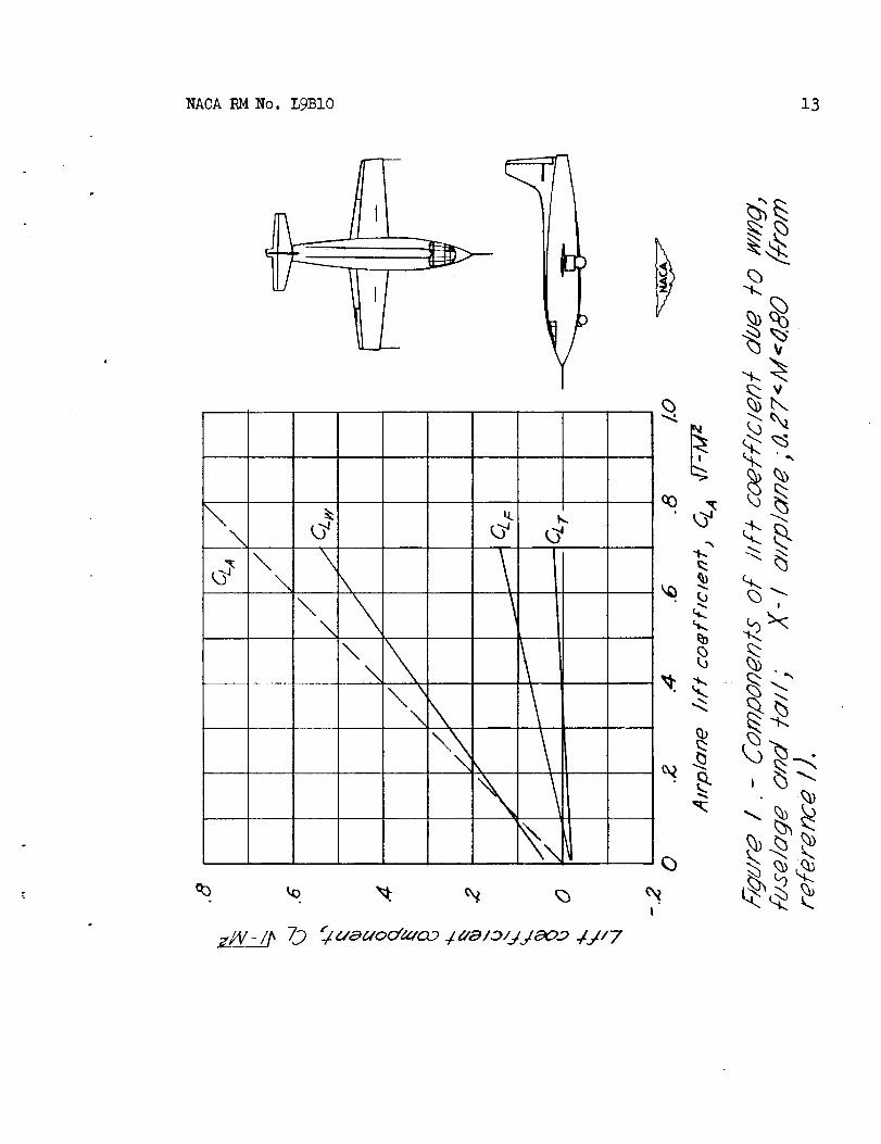
Figures I and 2 present the available data which are directly
applicable to show the division of the air load. The data shown in these
figures are derived from flight measurements of wing and tail loads by
means of strain gages located near the wing--fuselage and fuselage-tail
Junctures. The over-all loads on the airplane were determined from
accelerometer measurements and from a knowledge of the airplane weight.
4
NACA RM No. LgB10
Figure I shows CLV_--_ _ due to wing, tail, and fuselage of the
X-1 airplane (previously designated _5-i) plotted against CLAVe- M2.
The curves were taken directly from reference i. The data shown inthe figure cover a Mach number range from 0.27 to 0.80. Figure 2
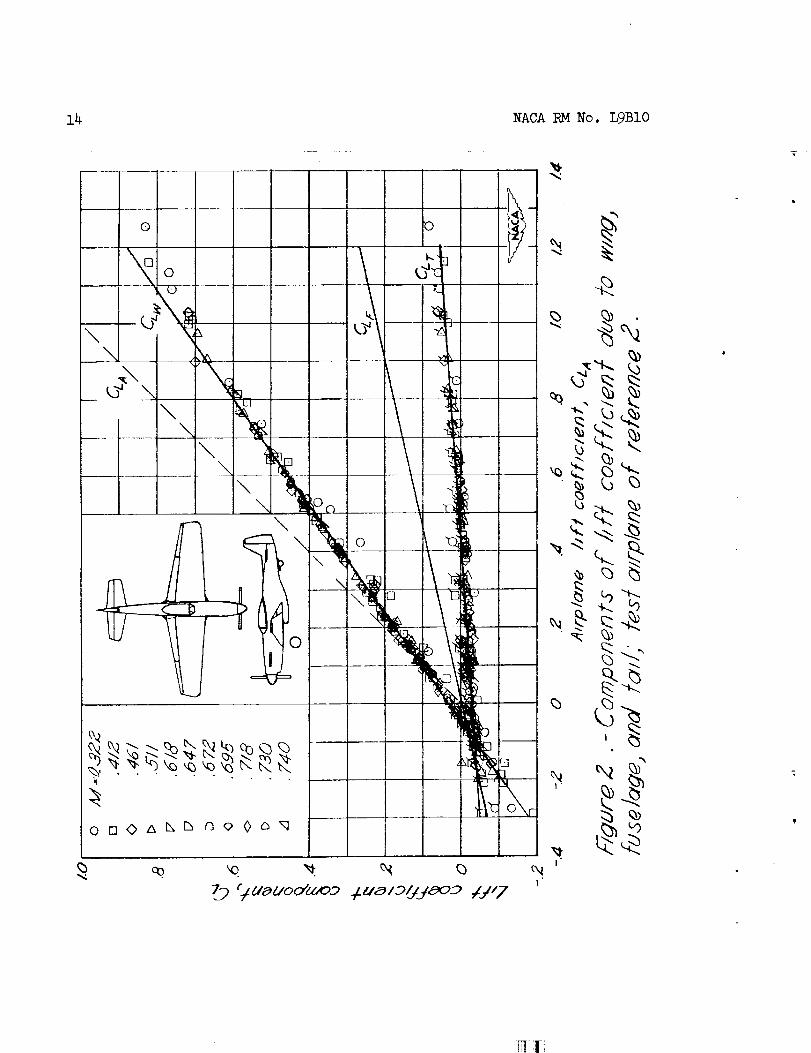
shows CL due to wing, fuselage, and tail for the test airplane of
reference 2 plotted against the airplane lift coefficient. The curves
of figure 2 are based on data obtained during the tests reported inreference 2; these data cover Math numbers from 0.32 to 0.7_.
The factor _l - M2 in figure i in both the ordinate and abscissa
appears in the original figure in reference i. This factor was not
used in the preparation of figure 2.
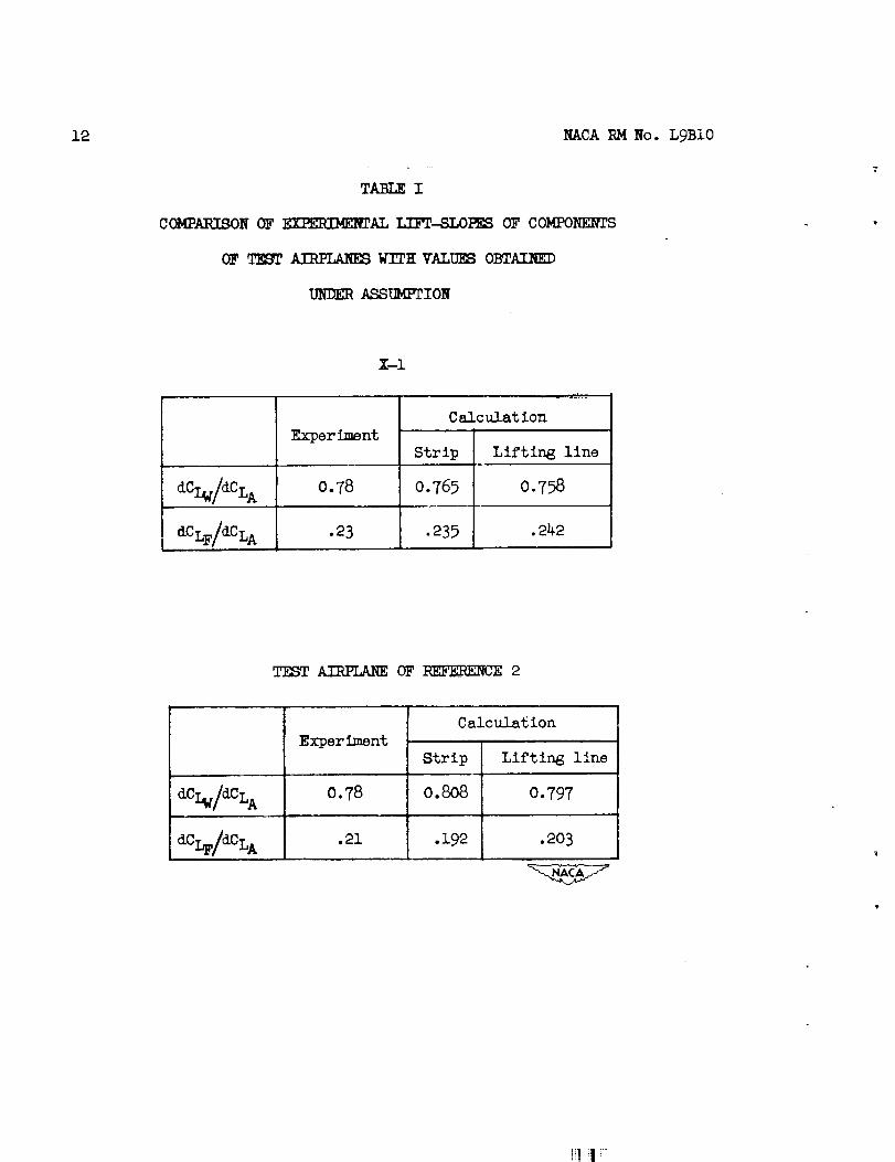
Table I presents a comparison of the slopes of the experimental
curves of figures 1 and 2 with theoretical values. In computing the
theoretical slopes the assumption that fuselage lift in a wing--fuselagecombination is proportional to the wing area blanketed by the body (or
more properly in the present cases, wing area between strain-gage
stations) is used. The experimental data of the figures were reduced to
the status of a wing-fuselage configuration by adding the tail lift to
that of the wing. The theoretical slopes were determined by using both
strip and lifting-line theory.
Indirect Data
Figures 3 to I0 present data which, although not directly appli-cable to the problem of the division of air load, may be used to
obtain trends. The data in these figures were obtained from materialavailable in references 3 and 4. In these reports the forces dn the
wing and fuselage were first measured independently and then the totalforce on the combination was found. The tests were made at low spged
and at a Reynolds number of 3,100,000.
In analyzing these data several methods of presentation were
considered. As it is impossible to determine the distribution of the
load from data of this type, the change in lift caused by interference
between wing and fuselage is found. It is assumed that this incremental
lift coefficient acts on the wing in line with the common design
assumption that the wing carries all the load.
References 3 and 4 are concerned with the "lift and interference"
of the fuselage Z_CLF, which is the difference between the lift
coefficient of the wing--fuselage combination and that of the wing alone
at a given angle of attack.
[!! ! !
NACA RM No. LgBIO 9
Hence,
_L_ =CLWF- C%_ (1)
By definition
C_F -CLw_ + CLF_ +_CL(2)
where 2C L is the increment in lift due to the interaction between the
two components.
Consequently 2D L is
AD L = ADLF -- CLF a(3)
and the assumption is made that
mL =mLw (_')
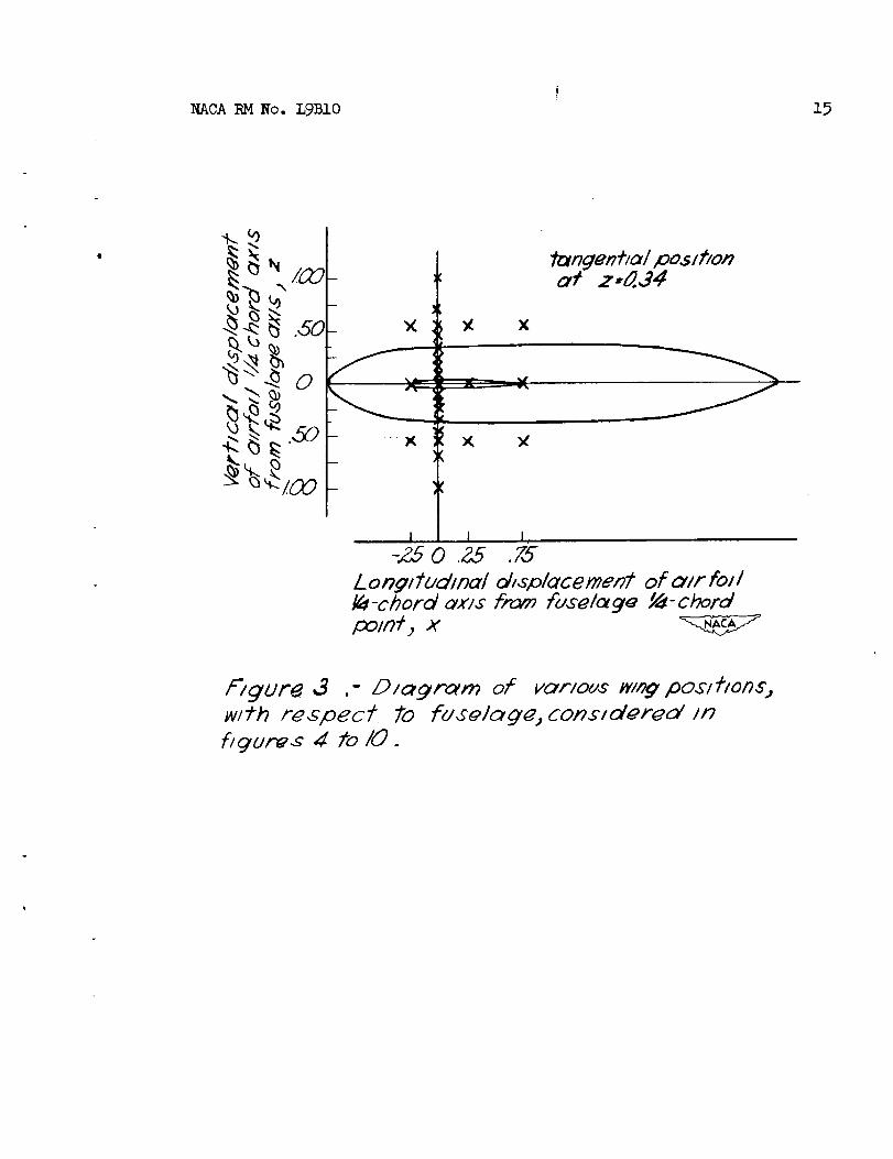
The vertical and horizontal wing positions with respect to the
fuselage considered are shown in figure 3.
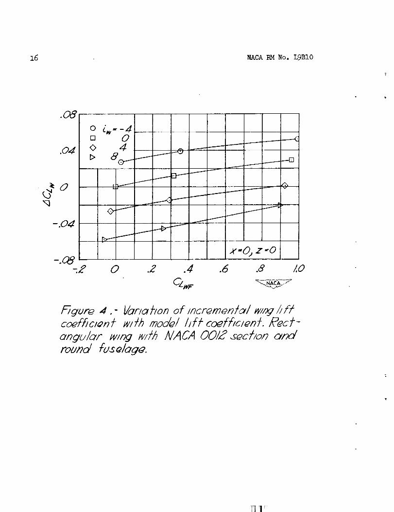
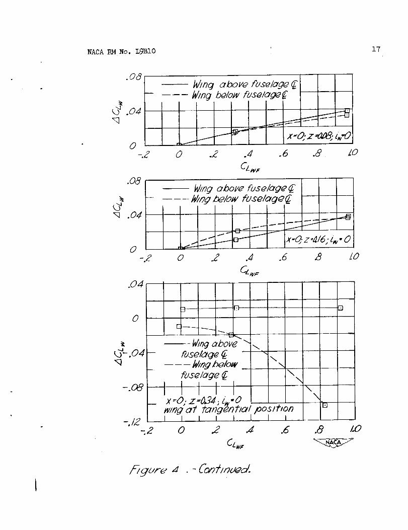
The variation of the incremental lift coefficient _CLw with model
lift coefficient at several wing angles of incidence over a wide range
of vertical and horizontal wing positions is shown in figure _ for a
model consisting of a rectangular wing with an NACA 0012 airfoil and a
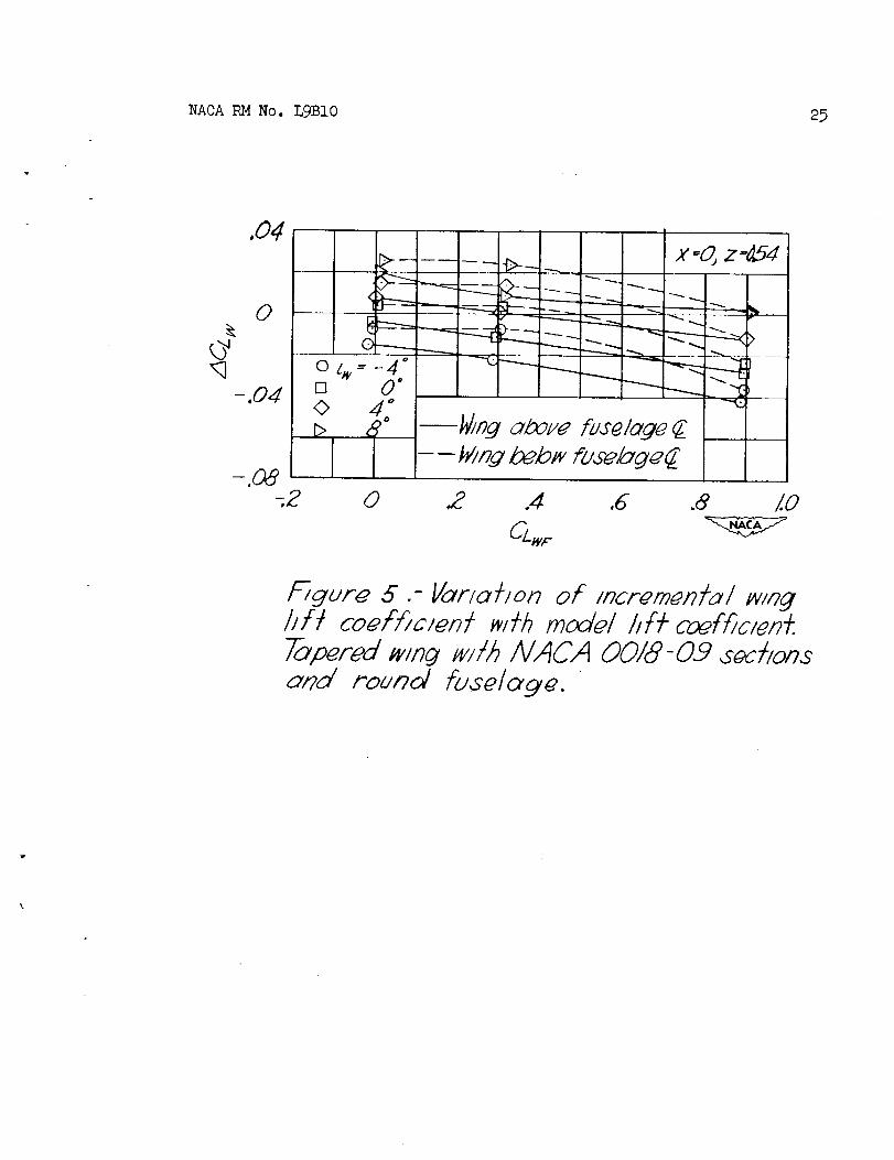
round fuselage. Figure 5 shows the variation of _CI_ with _ at
several wing angles of incidence and wing positions above and below the
fuselage for a model made up of a round fuselage and a tapered wing
with NACA 0018-O9 sections. The effect of varying the vertical position
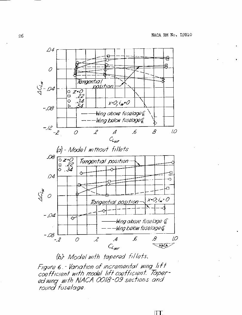
of the wing for this model with and without tapered fillets is shown in
figure 6. Varying angle of incidence at several vertical wing positions
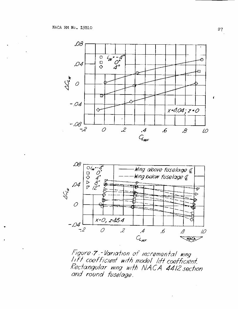
for a round fuselage in combination with a rectangular wing with
NACA hhl2 section is considered in figure 7. Corresponding tests on
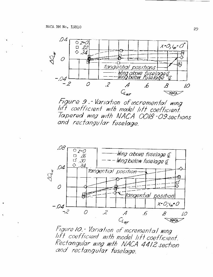
models with rectangular fuselages and wings with NACA 0012, 0018-09,and 4212 sections are given in figures 8, 9, and i0, respectively.
6 NACARMNo. L9BIO
The datum or reference condition for figures 4 to i0 is the combi-nation in each case with the wing one-quarter root chord point coincidentwith the fuselage one-quarter chord point (x = O, z = O) and with thewing at zero angle of incidence (i w = 0). Unfortunately in order to usethe results presented in these figures it is necessary to have a break-down of the air load such as is given in figures i and 2 for the datumcondition. The increment in lift measuredfrom the reference conditionof the given curves is then added to the corresponding value shownon thebreakdown curve.
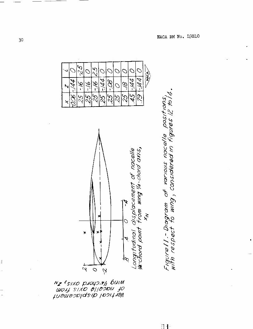
Figure ii showsthe various positions of the nacelle with respectto the wing considered in figures 12 to 14. These figures present indirectdata that apply to the effects of wing-n_celle interference on the componentloads. The data used were first presented in reference 8. The incrementallift coefficient as defined here is
-- Czw - CZWa(7)
Insufficient data were available to isolate the lift due to wing-nacelle
interference. Figures ii to 14 consider the effects upon the incremental
nacelle lift of varying the longitudinal and vertical position of the
nacelle on the wing and the nacelle angle of incidence with respect to
the wing independently of each other. The model consisted of a modified
NACA fuselage form Iii with a fineness ratio of 6.0 in combination with a
modified NACA 65-210 airfoil.
DISCUSSION
Lift on Components
The comparisons shown in table I indicate that the assumption thatfuselage lift is proportional to the area of wing blanketed by the body
iS valid over the Mach number range covered by the flights for the two
airplanes_for which data are available. The discrepancies between flightand theoretical results may be due in part to the distribution of the
tail lift between the other two components; the assumption that tail
lift is entirely carried by the wing outboard of the strain-gage stationsnot being wholly correct.
The analysis of the data of figures i and 2 indicate littleapparent variation of the division of the air load among the components
of the airplane with Mach number within the range of the available flight
tests.
NACARMNo. L9BIO 7
The measurementsof wing and tail lift coefficients for theX-i airplane are accurate within _O.02_. The accuracy of the measure--merits of wing and tail lift coefficients of the test airplane ofreference 2 was estimated to be within 20.02 and +-0.009, respectively.The factor CLA was estimated To have a maximumerror of about iO.O4 atthe highest lift coefficients.
The effect of changing airplane center-of-gravity position on thedistribution of the air load was found to be negligible for the testairplanes of figures I and 2. In the cases of larger airplanes, it isconceivable that movementof the airplane center of gravity may affectthe componentloads more noticeably. In general, a forward center-of-gravity movementwill tend to decrease the tail lift, negative tailloads becoming more negative, while the wing lift will experience acorresponding increase.
Wing--FuselageInterference
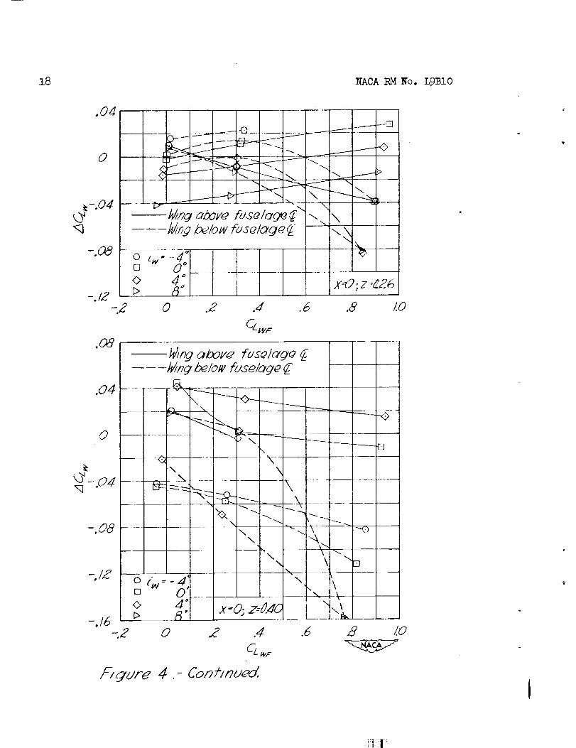
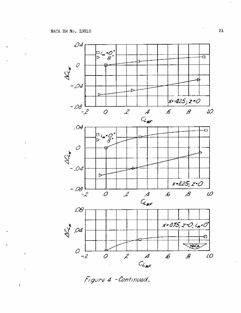
The results of the tests summarizedin figure 4 show the incrementallift coefficient (assumedto act on the wing) to vary regularly withmodel lift coefficient and wing incidence except at vertical wingpositions near the tangential where the variation becomesquite irregular.
At wing positions from z = 0 to z = 0.26 there is seen to be verylittle variation of _ with the lift coefficient of the combination.Increasing wing incidence tends to decrease the incremental liftcoefficient, while the variation of _DI_ with the wing vertical positionis negligible.
As the wing approaches the tangential position between z = 0.26and z = 0.40 marked changes occur in the incremental lift coefficient.Its variation with the model lift becomesirregular, and the coefficientitself may attain unusually high values.
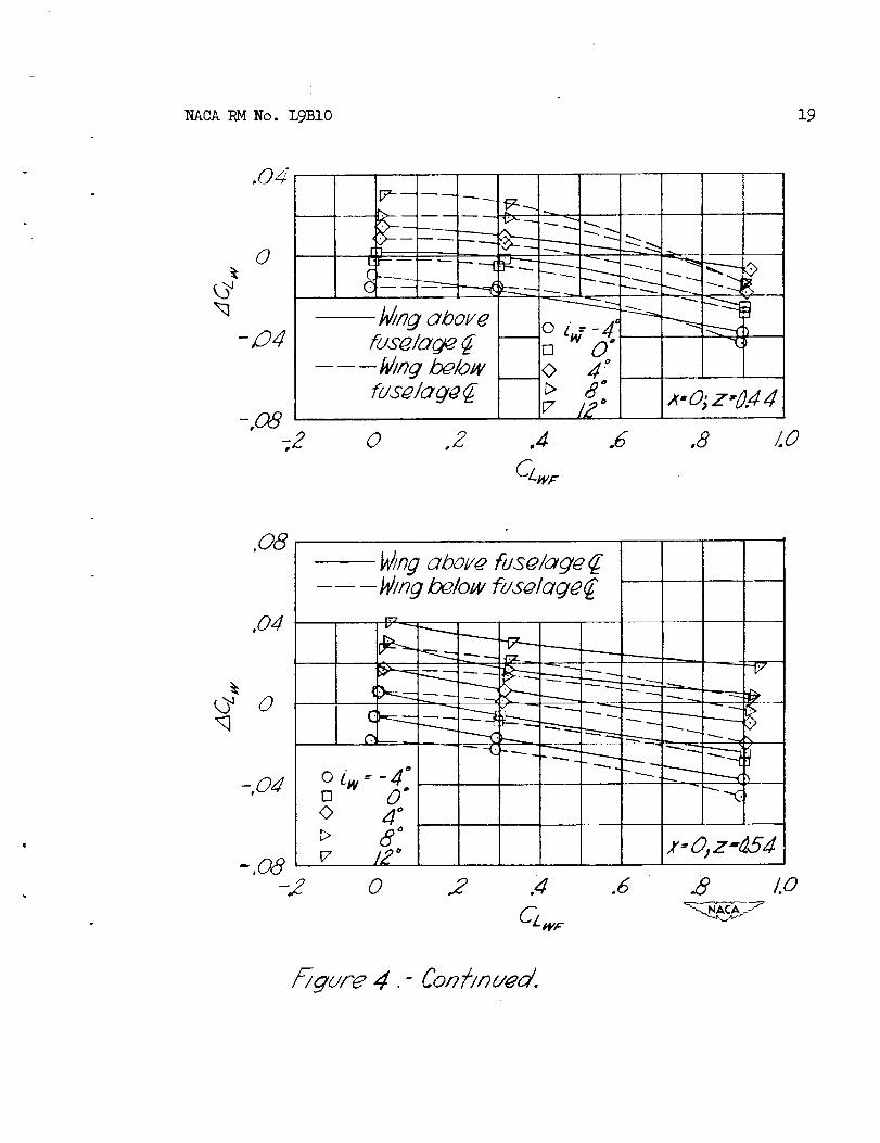
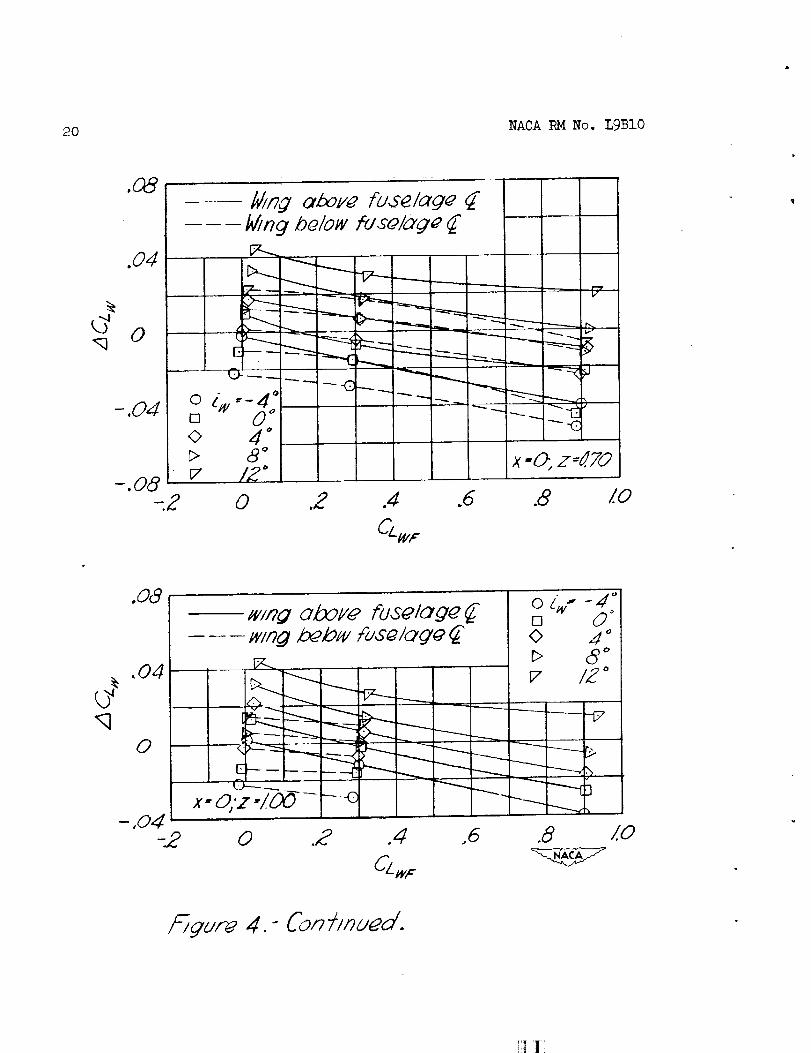
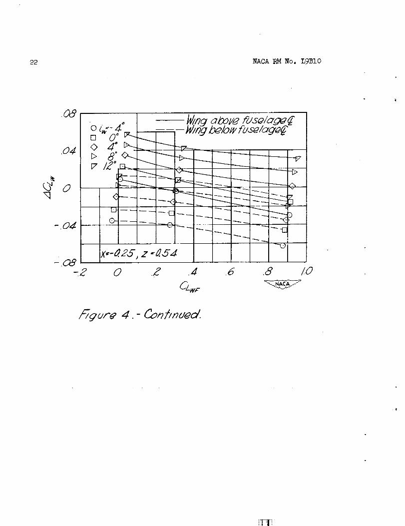
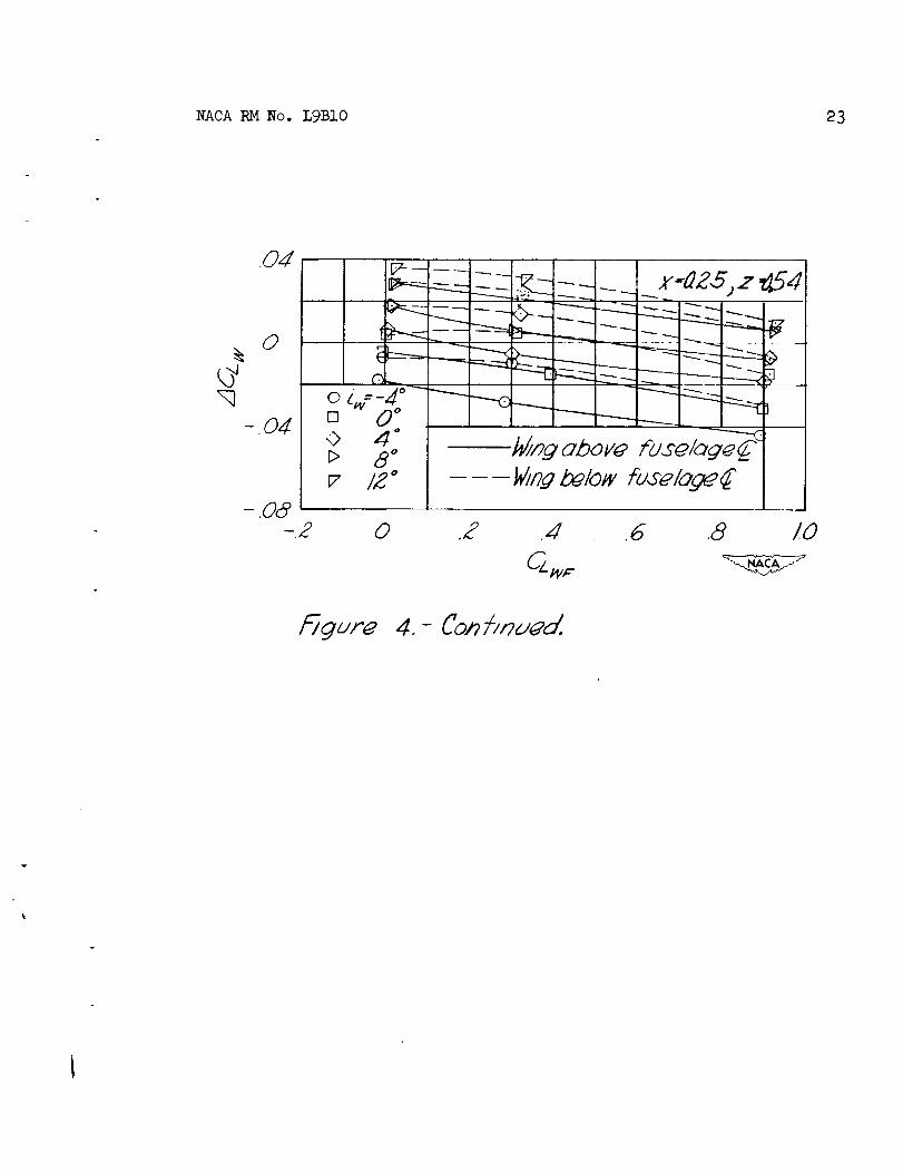
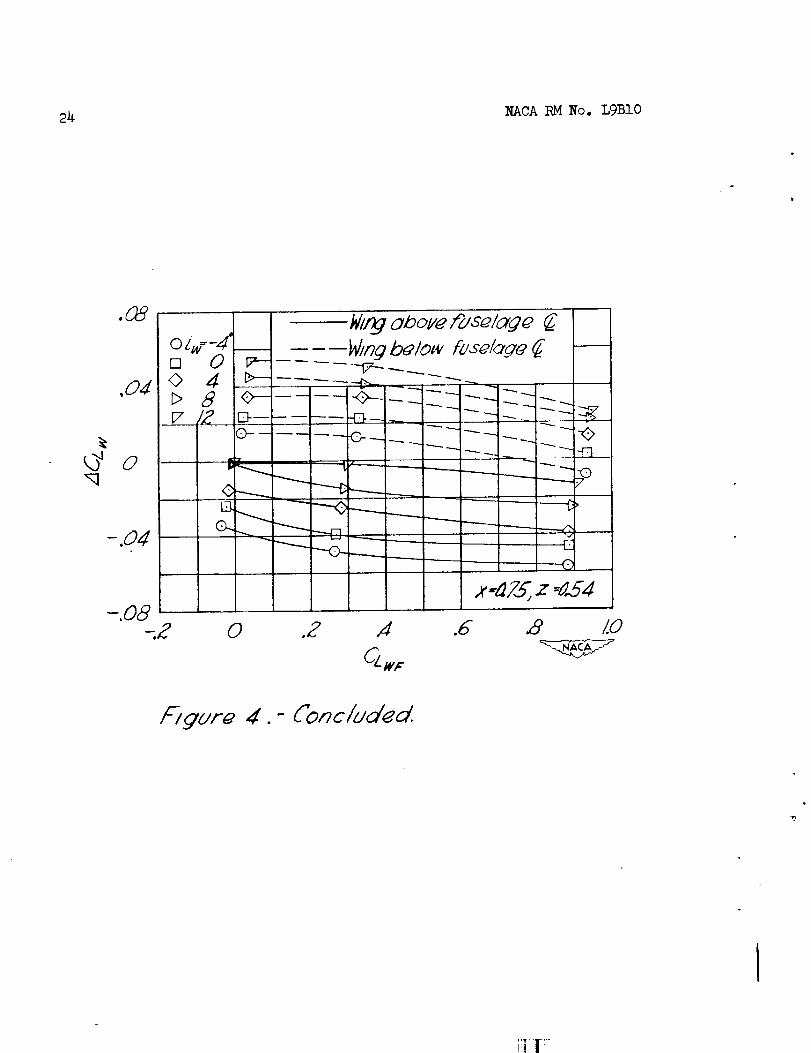
At wing positions above the fuselage from z = 0.40 to z = 1.00 t_evariation of ACLw with CLw and with iW becomesregular again. Thereis little difference in the value of the incremental lift coefficient atcorresponding positions above and below the fuselage center line. It maybe seen from the figure that increasing wing incidence will increase theincremental lift coefficient at these wing positions.
Figure 4 shows a slight increase in the value of ACI_ at the higher
model lift coefficients as the wing is moved longitudinally toward the
rear of the fuselage. At the most rearward position tested, a small
decrease in the value of the coefficient was noted. At wing positions
above the fuselage, ACI_ is seen to decrease as the wing moves rearward.
8 NACARMNo. L9BIO
A corresponding increase in the incremental lift coefficient was noticedas the wing movedrearward below the fuselage.
The substitution of a tapered wing with NACA0018-O9sections intothe combination of figure _ caused a decrease in the incremental liftcoefficient with the wing above the fuselage and an increase with thewing below the fuselage. (See fig. 5.) At wing positions on thefuselage, a decrease in ACLw was noted with the wing at and below thecenter line, an increase occurring with the wing above the center line.Results at the tangential position again showedlarge changes takingplace. (See fig. 6.)
The addition of fillets to this model (fig. 6) caused noticeableincreases in 2_CLwwith the wine at and above the fuselage center line;
decreases in ACLw were observed at wing positions below the fuselagecenter line.
A rectangular wing with NACA4_12 section caused a decrease in ADLwfrom the values observed in figure _ with the wing at the fuselage centerline. (See fig. 7-) At wing positions off the fuselage, an increase wasnoted.
The addition of a rectangular fuselage to the combination offigure 4 results in a decrease in the incremental lift coefficient atwing positions on the fuselage and above the center line and an increasewhen the wing is below the fuselage center line. (See fig. 8.) Anincrease in 2DLw was noted at both tangential positions, and at wingpositions off the fuselage an increase resulted above and a decrease below.
The addition of fillets to the model of figure 8 caused a decreasein _CLw with the wing at the fuselage center line and an increase at awing position on the fuselage and below the center line. The change inthe incremental lift coefficient at the wing position on the fuselage andabove the center line was insignificant.
Substituting wings with NACA0018-09 and NACA4412 sections into thecombination of figure 8 (figs. 9 and i0) causedtrends similar to thosepreviously observed in figures 5, 6, and 7.
The results presented in figures 4 to i0 indicate that theincremental llft coefficient is affected to a greater extent by positionchanges of the wing with respect to the fuselage than by modificationsto the model. The vertical position at which the wing was tangent tothe fuselage caused the greatest change in the incremental lift coefficient.Lesser variations were caused by wing incidence, The incremental liftcoefficient is affected to the next greatest extent by the presence offillets. Increased wing camber (NACA4412 airfoil) will result in a lesserchange in ACLw while varying fuselage shape and the introduction of wing
if!li
NACA RM No. L9BIO 9
taper and increased root thickness (NACA 0018-09 airfoil) account for
still smaller variations. The effects of varying the horizontal
position of the wing on the fuselage are negligible.
The accuracy of the data of figures 4 to l0 is the same as that of
the usual airfoil tests. (See reference 9.) In general, the error in
the measured lift coefficient is not greater than _).02.
Wing-Nacelle Interference
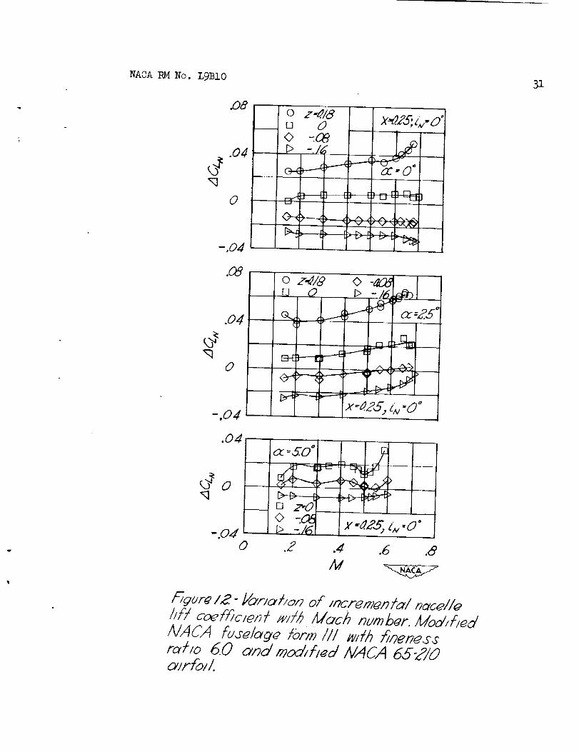
Figure 12 shows that at 0° angle of attack the nacelle in the
midposition (Z = 0) has a slight positive lift. Lowering the nacelle
reduces the lift increment. The nacelle in the high position (Z = 0.18)
contributes some lift, which, unlike that measured for the otherpositions, increases with Mach number. At the higher angles of attack
the lift increments become more positive with increasing Mach number.
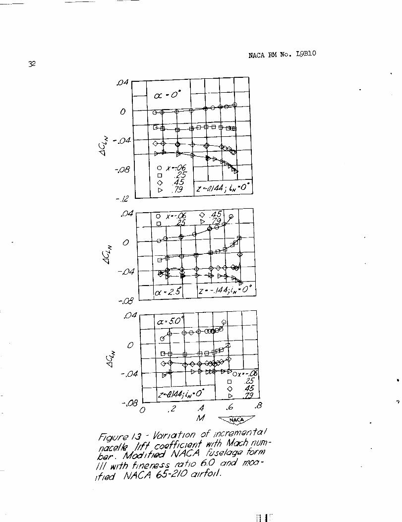
The results of the tests of the horizontal variation of nacelle
position (fig. 13) show that moving the nacelle forward on the wing
increases the loss in lift due to the nacelle. The lift increments
decrease with increasing Mach number for the more forward positioms ofthe nacelle at an angle of attack of 0°, and for rearward nacelle positions
as the angle of attack increases.
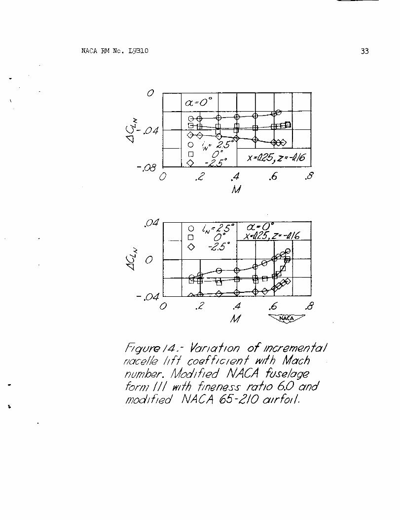
The results from the angular variation tests, shown in figure 14,
indicate the lift to be greatest for the nacelle having a positive angleof incidence. The lift increments become more positive with increasing
Math number at the higher angle of attack.
Figures 12 to 14 indicate trends similar to those previously
noted for wing--fuselage combinations. The variations in 2_CLN due to
increasing Mach number are so small as to be negligible within the range
of the tests. The effect of the angle of attack upon the incremental
lift coefficient appears to be insignificant for the attitudes tested.
The test points from which these curves were plotted indicate
maximum discrepancies in ACLN between 0.002 and-O.O0_.
Although the results presented in figures 3 to 14 seem to contra-
dict the consistency of these data of figures i and 2 and table I, thesemay be due to the breakup of the interference lift between components.No definite conclusions can be drawn from this data unless tests of the
datum configuration in which loads are measured on the wings in the
presence of the fuselage were available.
i0 NACARMNo.L9BIO
CONCLUSIONS
An analysis of the available data on the effects of wlng-fuselage-tail and wing-nacelle interference on the distribution of the air loadamongcomponentsof airplanes has led to the following conclusions:
1. There is little apparent variation of the division of the airload between the componentsof the airplane with Machnumberwithin therange of the available flight tests. As a result, the present assumptionthat fuselage lift maybe considered as the lift acting on the portion ofwing area blanketed by the body is valid over the subsonic Machnumberrange in the cases of the two airplanes.
2. The incremental lift coefficient due to the interference variesregularly with model lift coefficient and wing incidence except atvertical wing positions near the tangential. Here large changes in theincremental lift coefficient becomeevident.
3. Other variables such as horizontal wing movement, angle ofincidence, filleting, fuselage shape, and airfoil section influence theincremental lift coefficient to lesser degrees.
4. Nacelle incidence and position affect the incremental liftcoefficient as in wing-fuselage combinations. The effect of Machnumberupon the coefficient is negligible within the range of the tests.
9. Although indirect data have been analyzed to obtain trends, theyare not applicable to determine the division of the air load amongthecomponentsof airplanes. Further direct experimental data are necessarybefore indirect data maybe used to determine the division of load.
Langley Aeronautical LaboratoryNational Advisory Committee for Aeronautics
Langley Air Force Base, Va.

NACARMNo. L9BIO ll
REFERENCES
i. Beeler, DeE., and Mayer, John P. : M_asurementsof the Wing and TallLoads during the Acceptance Tests of Bell XS-1 Research Airplane.NACARMNo. LTL12, 1948.
2. Aiken, William S., Jr. : Flight Determination of Wing and Tail Loadson a Fighter-Type Airplane by Meansof Strain-Gage Measurements.NACATN No. 1729, 1948.
3. Jacobs, EastmanN., and Ward, Kenneth E. : Interference of Wing andFuselage from Tests of 209 Combinations in the N.A.C.A. Variable-Density Tunnel. NACARep. No. 5_0, 1935.
h. Sherman, Albert: Interference of Wing and Fuselage from Testsof 28 Combinations in the N.A.C.A. Variable--Density Tunnel.NACARep. No. 575, 1936.
5. Lennertz, J.: On the Mutual Reaction of Wings and Body. NACATMNo. 400, 1927.
6. Multhopp, H.: Aerodynamics of the Fuselage. NACATMNo. 1036, 1942.
7. Spreiter, John R.: Aerodynamic Properties of Slender Wing-BodyCombinations at Subsonic, Transonic, and Supersonic Speeds.NACATN No. 1662, 1948.
8. McLellan, Charles H., and Cangelosi, John I.: Effects of NacellePosition on Wing-Sacelle Interference. NACATNNo. 1593, 1948.
9. Jacobs, EastmanN.j Ward, Kenneth E., and Pinkerton, Robert M.:The Characteristics of 78 Related Airfoil Sections from Testsin the Variable-Density Wind Tunnel. NACARep. No. 460, 1933.
12 NACARMNo. L9BI0
TABLEI
COMPARISON OF E_AL LIFT-aLOPES OF COMPONENTS
OF TEST AI_ WTTH VALUES OBTAIXED
UNDER ASSUMI=rION
X-1
r
dCLF/dCL A
Experimsnt
Calc ulat ion
Strip Lifting line
dCLw/dCLA O.78 0.765 0.758
.23 .235 .242
TEST _ OF __E 2
Experiment
Calculation
Strip Lifting line
O.808 O.797
.192 .203
Frill-
NACARMNo. LgBIO 13
\\
" 1\
\\
7,_:_/ua uoc:_o___/:_:a/o//./ao: -/.//7
14 NACARMNo. L9BIO
I----I----
o_ I O
w---_-. , L
\
i
r'.-= I
\
I
1
o
\\
\
D
_'c o\_
I/j".Z
-_<_
I
ii I
NACA RM No. L9BIO
I
-250
Iomgent/alpos /t/onat z-d.3d
X
Long/tudma/ d_spl_cement of _/rfoilY4-chord_x/sfrom fusel_ _-chord_m_ _ x
16 NACARMNo. L9BI0
.O8
.O4
0 _=-_[] 0<> 4
/
I
II
-.08-.2 0
i_______-----(I
f .--ky
--6]i f
/i
f-Z}-'--
--4>-/
J/
J
I
/
_/h
2" =0_ Z "0
.2 .4 .6 .8 1.0
I_gurq .4.- Vor/o lion of Jncrqmqnt_l wJr_]/J ftco_f[IC/_n_ WlJh mOO�q� /l_f co_/_lclen7 _. t_ec_-
_ngul_r w_ng_J_ IVACAO01Z_ecfJon c_nctround fu_lege.
i] !
NACA RM No. L9B10 17
.0_
.Od
.O8
.04
0
.0_
.2 .4 .6 .8 ZO
I
fI f
Wing obo//e fuselage
_og below fumel_gq_I i I I I I
f
x-O/z-a/6: _.- 0
0 .Z .Z .6 2_ I0
0
..j
L)- .04 --
--.Oc_
-./Z_2
_n9 _bove \
fu%elo/cl_ _ -Al/ng bt#ow ....
fuse�age1 1 t t 1I I I I Ix--O;z-a3Z;_w.ow/n_ at tangential po_/t_onI l I I I I i i
0 .2 ._ .6
CLw,_
\\
\\
\\
7.
[]
F/ qur_ - Conl_nue_
18 NACARMNo. L9BI0
.O9
.O4
0
,q .O4
-.08
-,12_
CLIFF
x_O ; z ¢X6
,8 lO
i
i
I
4
"O i
[]
b
\
W t.0
,F-/_'Ur6'4 .- Conhnu_,
ill;|_
NACARMNo. L9BIO 19
O
.0_
0 ,2 .4 .6 ,8
CLwF
/.0
<?,q
,O8
.O4
0
-,04
Win9 abo_e {use/ageWing_Io_ fuselage_
0 {W---4 °[] 0 °
0 4 °> 8 °V /2 °
0 2
x-G z.._54
.4 .6 .8 LO
/_gore 4.- Co,,2hnuecl.
20 NACARMNo. L9B10
.08
.O4
0
-.04
-.08
.08.
.0_
0
-2
L_",_-5.__.-.._ _ _'_"-"-"_-__
o%.-4 °[] 0"© 4 °
I,_ °
0
x.,O, z--_.70
.6 /.0
_/n_ atoye fdse/age
x.. O,'z -/Oc_ _ _ -c
0 .2
E
,6.4z
CL wF
o l_:-4"[] 0 °0 4 °D c_°_" /Z °
-----_[7
.8 /0
NACA _4 No. L9BI0 21
0
____o _ :,0"
cJ
- .04
04
0
- .0,4
- .08--.f
.C6>
.O4
0
f
/
.Z
J
iI
f
J
r,._.J
ii
x.:-_25: z - 0
.6 .8 iO
s--H3
0 ,2 ,4
C--zw:
JJ
JJ
J
,6 .<9 1.0
.6
, I
.8 I0
F//gur_ 4 -Conf/nued,I
22 NACARMNo. L9BI0
O8
.04_
0
-.O4
-Z
o
o __--_[] 0 ° G--
W/Z°E___
n<7 alooy_ fd_@lo_ _l I_Io_I fuz_logo_
"7
_--- --f7
v
--_>
"-_ IZ
.zl .6 .8 I0
_g ure 4. - Co_hnued.
NACARMNo. L9B10 23
O4
0
O4
• . .... • ....... p.
-.*-._.___
0 _-Z_ °_'--"
[] O °4 °
_> 8 °IB°
_ng above Fu_@loge_"
_ng b_lo# fu_elo_
0 .Z .W .6
CL_,F
.8 I0
kTgure 4. - Conhnu_d
¥
°
24 NACA RM No. L9BIO
.OS
,Od
0
-.Od
OZw--,d'_[] 00 4> 8
_nga_over_se/a2e¢_n9 b_to_v fuselage
_-- -- .... "17-'-.----...._
[] _---_
E_
_7-.--.._,_..._
,...-.._.__
E
..@
0 .2 A
CL#F
x .,z27.5,,z :45.<z
.6- W /.0
_ur_ 4.- Concluded.
i_ilI !-
NACARMNo. L9B10 25
.Od
0
x:o, z-_
---_ng almye melage
_ng loelo_vfo',s'eb,@,_o_
0 Z .4 ,6 ._ I0
Ci_
i_-i_Turoo 5 -Yolrlahon of Incrgmun;idl llvln_#hfl co_£Kcient w_h model kf_ co_fFicmn_.Tapered _in9 #ilk IVIICA 0018-09 _oclions_nd round fuselage.
26 NACARMNo. L9BI0
,O4
0
.O8
.O4
L
\
- -O
.6 B /.o
_ndj_nf/ol/izz/t/on--\_._.---!
0 z--O2Z
0.34
I
.[9_..--I I
<..-
i----<J
......--
!'T_V
NACA RMNo. L9BI0 27
q
.O8
,04
0
- 04
II' m O
°[]
f
i
J
//
Er
f
_J
f
f
i
_Ji
f _D
f_
jv
0 .2 .4 .6 .8 1.0
CAw#
,OB
.O4
0
0 .2 .4 .6 .8 1.0
CL_
h it cO01CflCl_,gt w,'th rood& /if/c_ftTCl_'ni.,_'_'cl'onqulor win_ wilk /VACA 4dlZm_c/lon
mind round fuselo/g_.

28 NACA RMNo. L9BI0
.P4
0
-.04OZ'O0 .Z80 .J4_> .,94
__:_-.
_-- <-=- L---'riP___
_ngen/+/al pos///on _ \ G-O,,x-0\
\
-.08 _,_gbelo#:ds_:mg:.._ _>-.Z O 2 .4 .6
CLwF
(a)-/I//odel_/:kou/6 lieIs.
.8 I0
.O8
.O4
0
-.04
_ng oboye £uzela9_ q
_ng belo_ fo_elageq
i I
_,j i//
0."--/
/ f
C /- ____4}__-->----
.____--_
_;,--o,.x--o
-.Z o .2 ,i .6 .8 1.0
{b)-Mocielm#h hpemd hlhM.
:'/gur_ 8 .-Vo/r/ohon of incren_n/u/ _//ng�l/r/
co:::/c/:n/w//hmodel hF/ co_ff/cmn/./%c/ang-ul_r?:/ng/_/lhNACA O01Z _c//on end rec/an_/-
UkTr fuselage,
_!I_
NACARMNo. L9BI0 29
.O4
0
o .2 A .6 .8
I_gur@ 9 .- Vari_]/on ohncr_rn_n/u/ wing
hFl coEFhclenl _#h m_el hi� codhcJ_nlTap_r_o/ _mg _ith IV/CAond rco_ongu/_r fU_@Iclg@.
1.0
O01g -09._c Dona
_G
.08 o z--O '
,0_
0
V
-.04-,Z 0 .2 ,4 .d # ZO
t_gur8 I0.- Yofi_fion of incrmm_ntol wingliP� coeffic, i_nt _ltk model/if/coGfficlsnt.
£_omfc_nyu/olr _Ing 14111kIVAUA 441Z m_chon
_n_l r_cl_nyular fus_l_g_.
3o NACA RM No. LgB10
r ,, . .-.
Q
_o
NACARMNo. L9BIO 31
DB
.0#
0
.O4
0
z-_./B0
0
[]
0t>
,,'v / V ", ",_,_ _
o zM/_ 0 _16.[] 0 _>
.W_.,0 °
C_.,,., L_.4
-.04
.04oc--SO°
_Dz.O0 -.08
-.Od i> -/60 .2
j_4
1QI
_NOx-#.ZS,"- °
>
x-0.¢5,e._.o"
.# .6 .8
M
I_gur_ IB "Yar,_I/on oF mcrem_n /_/ nacel/_
//?/coef/)c/_nt ,_//b Moth number. Modified/VACA fu._elaq_ form fll mlh _n_n_.r_roDo 60 and moo, fled NACA 65Z/0
aer_,l.
32 NACA RM No. L9BIO
.O4
0
0_, w U °
-.Od<2
-.08
-.IZ
o x-=06[] .2,9o .45
.7_9
I,
z :o*/dd;&, "0"
.O4'
0
-_94
-.O8
_q
.O4
L9
-.04
_=S.O °
J
z- 14 i O"
J
[] Z._o .45D" .73
.6 .8
E_uP_ 13 - //_'rlahon of inor8moi?talnacel/_ /it'/co_f_c/en/talk ilda_h nurn-b_r. Adodifl_d AI,4CA _el_ge Portotll _l#h //nen@_ ro_/o 6.0 c_noi moo-iliad tVACA 65"2/0 oirPoll.
NACA IbM No. L9BI0 33
O
_- .o#,q
_ =0 °
[] d) °
© -Z..q°
]- L
x--#25,z--41#
.6 .8
_q
,0_
0
/_ur_ /d.- Vor/a_/on olc/ncremenJo/#oc_//_ //H co_{fJc/en!_wlhMuchnumber.ModJ_ed NACA fu_e/o_efor1_?I//#<Ibbn_nes_folio6.0ondmodJl)ed AIACA 65-ZI0 o/rFoll.

_e
It! 1_: