Embed Size (px)
Citation preview
NATIONAL BUREAU OF STANDARDS REPORT
3790
EFFECT OF ENGINE AND FAN SPEEDS ON THE CAPACITY OF THE1/3-TON THERMO KING REFRIGERATING UNIT, MODEL Q15G
by
C. W. PhillipsMinoru FujiiP. R. Achenbach
Report to
Mechanical Engineering DivisionHeadquarters, Quartermaster Research & Development Command
Natick, Mass*
U. S. DEPARTMENT OF COMMERCE
NATIONAL BUREAU OF STANDARDS
U. S. DEPARTMENT OF COMMERCESinclair Weeks, Secretary
NATIONAL BUREAU OF STANDARDSA. \ . Astin, Director
THE NATIONAL BUREAU OF STANDARDSThe scope of activities of the National Bureau of Standards is suggested in the following listing of
the divisions and sections engaged in technical work. In general, each section is engaged in special-
ized research, development, and engineering in the field indicated by its title. A brief description
of the activities, and of the resultant reports and publications, appears on the inside of the backcover of this report.
Electricity. Resistance and Reactance Measurements. Electrical Instruments. MagneticMeasurements. Electrochemistry.
Optics and Metrology. Photometrv and Colorimetrv. Optical Instruments. PhotographicTechnology. Length. Engineering Metrology.
Heat and Power. Temperature Measurements. Thermodvnamics. Cryogenic Physics. Enginesand Lubrication. Engine Fuels. Cryogenic Engineering.
Atomic and Radiation Physics. Spectroscopy. Radiometry. Mass Spectrometry. Solid
State Physics. Electron Physics. Atomic Phvsics. Neutron Measurements. Infrared Spectros-
copy. Nuclear Phvsics. Radioactivity. X-Ray. Betatron. Nucleonic Instrumentation. Radio-logical Equipment. Atomic Energy Commission Radiation Instruments Branch.
Chemistry. Organic Coatings. Surface Chemistry. Organic Chemistry. Analytical Chemistry.Inorganic Chemistry. Electrodeposition. Gas Chemistry. Physical Chemistry. Thermochemistry.Spectrochemistry. Pure Substances.
Mechanics. Sound. Mechanical Instruments. Fluid Mechanics. Engineering Mechanics. Massand Scale. Capacity, Density, and Fluid Meters. Combustion Control.
Organic and Fibrous Materials. Rubber. Textiles. Paper. Leather. Testing and Specifica-
tions. Polymer Structure. Organic Plastics, Dental Research.
Metallurgy. Thermal Metallurgy. Chemical Metallurgy. Mechanical Metallurgy. Corrosion.
Mineral Products. Porcelain and Pottery. Glass. Refractories. Enameled Metals. Concreting
Materials. Constitution and Microstructure.
Building Technology. Structural Engineering. Fire Protection. Heating and Air Condition-
ing. Floor, Roof, and Wall Coverings. Codes and Specifications.
Applied Mathematics. Numerical Analvsis. Computation. Statistical Engineering.
Electronics. Engineering Electronics. Electron Tubes. Electronic Computers. Electronic
Instrumentation. Process Technology.
Radio Propagation. Upper Atmosphere Research. Ionospheric Research. Regular PropagationServices. Frequency Utilization Research. Tropospheric Propagation Research. High FrequencyStandards. Microwave Standards.
^Office of Basic Instrumentation ^Office of Weights and Measures.
NATIONAL BUREAU OF STANDARDS REPORTNBS PROJECT NBS REPORT
1003~20-4$32 November 12, 1954 3790
EFFECT OF ENGINE AND FAN SPEEDS ON THE CAPACITY OF THE1/3-TON THERMO KING REFRIGERATING UNIT, MODEL Q15G
by
C. W. PhillipsMinoru FujiiP* R. Achenbach
Heating and Air Conditioning SectionBuilding Technology Division
to
Mechanical Engineering DivisionHeadquarters, Quartermaster Research Sc Development Command
Natick, Mass*
<NBS>
U. S. DEPARTMENT OF COMMERCE
NATIONAL BUREAU OF STANDARDS
The publication, r
unless permission
25, D.C. Such pi
cal ly prepared If
A in , 1 , ,, or In part, is prohibited
Approved tor public release by the. . Standards, Washington
Director ot the National Institute otreport has been specifi-
Standards and Technology (NIST) report for lts own use ,
on October 9,2015.

EFFECT OF ENGINE AND FAN SPEEDS ON THE CAPACITY OF THE1/3-TON THERMO KING REFRIGERATING UNIT, MODEL Q15G.
by
C. W. Phillips, Minoru Fujii, and P. R. Achenbach
ABSTRACT
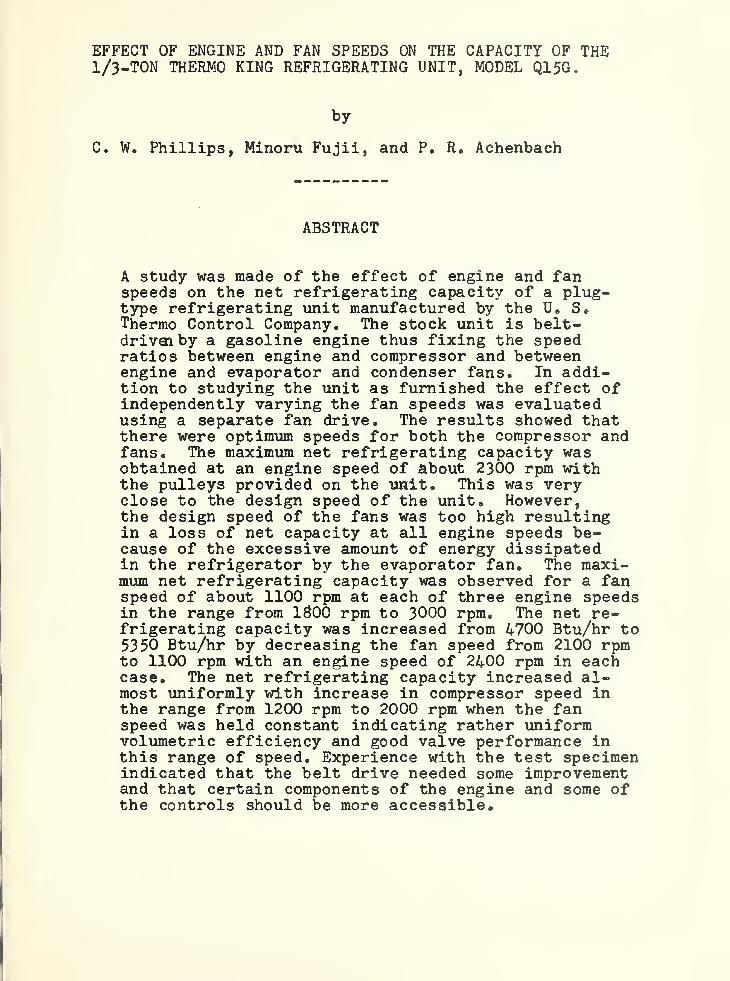
A study was made of the effect of engine and fanspeeds on the net refrigerating capacity of a plug-type refrigerating unit manufactured by the U. S.Thermo Control Company, The stock unit is belt-drivai by a gasoline engine thus fixing the speedratios between engine and compressor and betweenengine and evaporator and condenser fans. In addi-tion to studying the unit as furnished the effect ofindependently varying the fan speeds was evaluatedusing a separate fan drive. The results showed thatthere were optimum speeds for both the compressor andfans. The maximum net refrigerating capacity wasobtained at an engine speed of about 2300 rpm withthe pulleys provided on the unit. This was veryclose to the design speed of the unit. However,the design speed of the fans was too high resultingin a loss of net capacity at all engine speeds be-cause of the excessive amount of energy dissipatedin the refrigerator by the evaporator fan. The maxi-mum net refrigerating capacity was observed for a fanspeed of about 1100 rpm at each of three engine speedsin the range from 1&00 rpm to 3000 rpm. The net re-frigerating capacity was increased from 4700 Btu/hr to5350 Btu/hr by decreasing the fan speed from 2100 rpmto 1100 rpm with an engine speed of 2400 rpm in eachcase. The net refrigerating capacity increased al-most uniformly with increase in compressor speed inthe range from 1200 rpm to 2000 rpm when the fanspeed was held constant indicating rather uniformvolumetric efficiency and good valve performance inthis range of speed. Experience with the test specimenindicated that the belt drive needed some improvementand that certain components of the engine and some ofthe controls should be more accessible.

~!'V'
'
'
'
1. INTRODUCTION
At the request of the Office of The Quartermaster Generaltests were made as outlined in letters dated January 24th, May 2,
1951 and December 1, 1952, of a l/3-ton gasoline-engine drivenrefrigerating unit, Model Q15G, of the plug type manufacturedby the U„ S. Thermo Control Company of Minneapolis, Minnesota,It was tested in a 150 cubic foot, portable, walk-in refrigeratorof the type usually equipped with this size refrigerating unit inthe field* The refrigerator was employed as a calorimeter for thepurpose of thtese tests.
The purposes of this investigation can be divided into threemain parts as follows:
A. Measurement of the net refrigerating capacity of theunit at design compressor speed for a range of ambienttemperatures from 70°F to 110°F and at refrigeratortemperatures of 35°F, 0°F, and the lowest temperatureattainable without internal load in the refrigerator.
B. Investigation of the effect of changing the compressorspeed on net refrigerating capacity when the speed ratiosbetween the compressor, and the evaporator and condenserfans remained fixed at the design value. Investigationof the effect in the net refrigerating capacity of chang-ing the compressor speed independently of the fan speedsand vice versa.
C. Observation of the mechanical features of the refrigerat-ing unit with regard to their suitability for militarypurposes.
The results observed with respect to the above three object-ives are reported in Parts A, B, and C of the section on TestResults, respectively.
2. DESCRIPTION OF TEST SPECIMEN
The specimen refrigerating unit was identified as follows:
(NBS Test Specimen 54-51)U. S. Thermo Control Co., Minneapolis, Minnesotal/3»TonModel Q15GSerial Number
The unit was of the plug-in type and used Freon 12 as therefrigerant. The compressor was identified as Thermo-Kifig,

.
- 2 -
Model 2R, Serial Number 1051. The refrigerating unit was drivenby a gasoline engine manufactured by D. W. Onan & Sons, Inc. ofMinneapolis, Minnesota with the following nameplate data;
Model CK-MSSpecification 190JSerial Number 31-430271Maximum Horsepower 10.1 at 3,000 rpm
The condenser fan was of the propeller type made of castaluminum. It had 10 blades, 5-5/3" long, and the diameter was17 inches. Ambient air was drawn through the condenser, forcedaround the engine and compressor and discharged from the top andsides of the condensing unit section.
The evaporator fan was of the centrifugal type made of alumi-num plates. The fan wheel was 14-1/2 inches in diameter and 1-3/4inches in width. There were 17 fan blades which were 1-1/2 incheslong. The air was drawn into the evaporator from the front anddischarged from the top of the evaporator section.
The condenser and evaporator fans were mounted on oppositeends of a common shaft. The pulleys of the engine, idler, fansand compressor were connected in that order in a clockwise direct-ion by two V-belts. The diameters of the pulleys were 6-3/4",7", 7-3/$" and 10", respectively.
Five photographs of the specimen refrigerating unit areattached as Figures 1-5 inclusive. Figure 1 and Figure 2 showthe exterior views of the condenser and evaporator sections,respectively. Figure 3 is a three-quarter view showing thecondenser section with the perforated panels removed. Figure 4is a left side view of the condenser section showing the relativelocations of the engine, condenser fan, and compressor. Figure 5is the side view of the evaporator section showing the location ofthe evaporator fan.
The physical dimensions of the refrigerating unit were asfollows;
(1) Gross weight, without battery, lb. 533®
5

>“
-
- 3 -
(2) Overall dimension, includebattery, in»
(3) Condensing unit sectionwithout battery, in.
(4) Evaporator section, in.
(5) Plug Section, in.
(6) Compressor:a) Modelb) Serial Numberc) Typed) Bore, in.e) Stroke, in.f) Speed, rpm, designg) Displacement, cu. in.
(7) Condenser:a) Width, in.b) Height, in.e) Depth, in.d) Fin size, in.e) Fin spacingf) Tube size, in.
g) Number of tubesh) Series or parallel
i) Primary surfacearea, sq. ft.
j) Secondary surfacearea, sq. ft.
k) Total surfacearea, sq. ft.
l) Ratio primary to totalsurface, %
m) Tube materialn) Fin material
Wi dth Height Depth
34 59-3/8 32-1/4
34 50 19
27=1/2 28 10-1/4
28 28 3
2R10512 cylinder vertical2-1/41-3/4168013.91
2723-1/21-3/423-1/2 X 1-3/410 per inch3/S O.D.4S24 tubes in series per circuit,
2 circuits in parallel
10.6
134.3
144.9
7.3CopperAluminum

- 4 -
(3) Engine:a) Model numberb) Specificationc) Serial numberd) Type
e) Materialf) Speed, rpm, designg) Hated maximum brake
horse power at 3000 rpmh) Lubricationi) Fuel systemj) Ignition system
k) Cooling system
1)
Governor
(9) Evaporator:a) Width, in*b) Height, in.c) Depth, in.d) Fin size, in.e) Fin spacingf) Tube size, in.
g) Number of tubesh) Series or paralleli) Primary surface area,
sq. ft.
j) Secondary surface area,sq . ft.
k) Total surface area,sq. ft.
l) Ratio primary to totalsurface, %
m) Tube materialn) Fin material
CK-MS190J31-4302714 cycle 2 cylinder opposed
horizontal, air-cooledAluminum2400
10.1Force feedPump feed to carburetorSpecial 12 -volt motor-generatorbuilt into flywheel of engineprovided automatic starting,battery charging and ignition.Fan on armature of engine gen-erator forced air over engineblock and finned cylinder headsas directed by engine housing.Pierce Governor Company - GC-1403 2 1
242544 x 253 per inch1/2 0.D,3020 tubes in series per circuit
20.9
24.3
245,7
3.5CopperAluminum

- 5 -
3. TEST PROCEDURE
The specimen refrigerating unit was installed in a 150 cu, ft.portable, walk-in refrigerator for the capacity tests, which waslocated in a test room where the ambient temperature could be con-trolled. Refrigerator temperature was maintained at the desiredlevel by an electronic rheostat controlling the input to electricheaters which were used for the internal load. The heat output ofthese heaters was measured by means of watthour meters in the supplycircuits. Temperatures were measured by means of calibrated thermo-couples using an electronic, constant-balance type potentiometer.
The engine speeds were varied by adjusting the governor. Thecompressor, fan, idler, and engine were connected with a pair ofdouble-faced V-belts during Part A of the tests. Therefore, thecompressor and fan speeds were proportional to the engine speed asdetermined by the pulley ratio. During Part B of the tests, the com-pressor was driven by the gasoline engine and the fans were drivenwith a single V-belt by a 3/4 H.P. direct current motor installed ontop of the condenser section. The idler was eliminated and the engineand compressor were connected with two V-belts using the originalpulleys. The condensate drain fitting had to be removed in order topermit installation of these belts# The objective of this modifi-cation was to provide independent control of the fan and compressorspeeds so the fan speed could be determined for each engine speedthat would result in the maximum net refrigerating capacity* Thefan speeds were regulated by variable external field resistance andall speeds were measured by means of a stroboscopic tachometer.
After steady state test conditions were reached, they weremaintained for an average period of about 5 hours while observationsof pressures, temperatures, speeds, voltage, electric current andwattage were made at 30 minute intervals.
During the course of the capacity tests, some operationaldifficulties were encountered. They were recorded when they occurredfor reporting as a part of the operating experience with this unit.

'
4. TEST RESULTS
Part A
In preparation for the capacity tests, a test was madeto determine the heat transmission factor of the 150 cubicfoot, portable, walk-in refrigerator in Btu per hour perdegree cemperature difference. Refrigerator temperatureaveraged 35®3°F and the ambient temperature averaged 136*2 C Ffor eleven hours during steady state conditions.
^
The heattransmission factor was computed to be 23*62 Btu/'nr (°F tem-perature difference),,
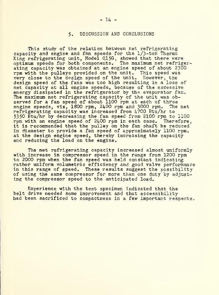
Results of the capacity tests with various engine speedsand proportional fan speeds at a refrigerator temperature of0°F and an ambient temperature of 110°F are summarized inTable 1 and shown graphically in Fig. 6. The engine speedbore an average ratio of 1.56 to 1 to the compressor speedand 1.11 to 1 to the fan speed during these tests. However,these ratios did not remain constant for all tests indicatingthat belt slippage was occurring during some tests. Thisproblem is discussed in Fart C of this report*
Fig. 6 shows that the net refrigerating capacity reacheda maximum value of about 4700 Btu/hr at an engine speed in theneighborhood of 2300 rpm. The net refrigerating capacitydecreased for speeds above and below 2300 rpm reaching a valueof l/3-ton or 4000 Btu/hr at engine speeds of about 1760 rpmand 2920 rpm*
It would be expected that the total refrigerating capacitof the compressor would increase proportionally with enginespeed if the volumetric efficiency remained constant* How-ever, the power required to drive the evaporator fan wouldincrease as the cube of the fan speed or the engine speed.Consequently, at some engine speed the rate of increase of compressor capacity would be eoual to the rate of increase ofevaporator fan power * Above this speed the net refrigeratingcapacity would decrease assuming that the heat transfer co~efficient of the evaporator surfaces remained constant throughout the speed range. This optimum engine speed was about2300 rpm on the test specimen which was approximately the de-sign speed of the unit
.
Table 1 shows that the comparative differences betweeninlet and outlet air on the evaporator and between inlet and

[
- 7 -
outlet air on the condenser remained reasonably steadyin the engine speed range from 1$00 rpm to 2700 rpm.This indicates that the total heat transfer in each ofthese components increased steadily with increase inengine speed since the air delivery of a fan in a givencircuit is proportional to the fan speed,, There was abouta 20 percent decrease in the temperature difference be-tween inlet and discharge air of the evaporator at anengine speed of 3000 rpm as compared to the lower enginespeeds indicating a decrease in the net refrigeratingcapacity.
The slow rise in discharge pressure and the gradualdecrease in suction pressure with increased engine speedindicate a steady increase in the total amount of heattransferred by the condenser and evaporator, respectively.The greater air flow over the condenser and evaporatorsurfaces does not significantly change the heat transfercoefficient inside these heat exchangers. Consequently,a greater temperature head was recuired to exchange moreheat between the refrigerant and these surfaces.
If it were assumed that the compressor capacity wasdirectly proportional to engine speed and the power ab-sorbed by the evaporator fan directly proportional to thecube of the fan speed during this series of tests, the netrefrigerating capacity of the unit could be expressed byan equation of the form:
R = AS - BS3 where
R is the net refrigerating capacity in Btu/hrS is the engine speed in rpmA and B are constants which can be evaluated using
the observed values of R and S for two test conditions.
Using values of R taken from the curve in Fig. 6 forS = 2100 and 2400 rpm, respectively the following relation-ship is obtained:
R = 3.09S - 0.00197S3 (1)
From this equation values of the net refrigeratingcapacity at other engine speeds in the range of the tests

have been computed and plotted in Fig. 6. The computedvalues fit the curve drawn through the observed valuesvery well except at engine speeds near 1800 rpm indica-ting that equation (1) adequately represents the relation-ship between net refrigerating capacity and speed overmost of the speed range tried.
The discharge and suction pressures and the airtemperatures at the outlet of evaporator and condenserwere probably affected to a small extent by the beltslippage revealed during some of the tests but these effectsare considered small compared to the broader capacity trendscaused by compressor displacement and power comsumption ofthe fans.
Fig. 7 shows the hourly gasoline consumption of theunit plotted against the engine speed. The relationshipwas approximately linear over the range of the tests. Thegasoline consumption per ton of net refrigerating capacityincreased steadily over the range of speed shown in Fig. 7and was slightly more than twice as great for a speed of3000 rpm as for a speed of 1800 rpm.
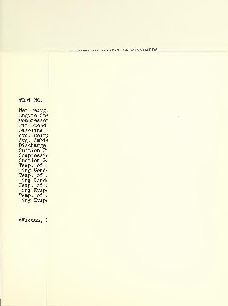
The relation between the net refrigerating capacityof the Thermo King Q15G unit and refrigerator temperatureis shown in Fig. 8 for four different ambient temperaturesranging from ?0°F to 125°F. At each ambient temperaturetests were made with refrigerator temperatures of 35°F,0°F, and the lowest temperature that could be attained with-out internal heat load. The observed results are summarizedin Table 2.
The engine was operated at a speed of about 1700 rpmfor these tests corresponding to compressor and fan speedsof about 1200 rpm and 1600 rpm respectively. However, therewas more than 100 rpm speed variation during the series oftests for each of the components: engine, compressor, andfans. These variations were caused by belt slippage insome cases but depended also on the amount of load on theengine. It was observed that the speed of the engine changedwith engine load considerably for a given governor setting.

- 9
Fig. 3 shows that the net refrigerating capacity variedapproximately in linear relation to the refrigerator tempera-ture at each ambient temperature » The capacity curves at thefour ambient temperatures are nearly parallel, convergingslightly as the refrigerator temperature decreased. On theaverage the net refrigerating capacity increased 140 Btu/hrper degree rise in refrigerator temperature for the three higherambient temperatures. At an ambient temperature of 125°F thenet refrigerating capacity increased 117 Btu/hr for each degreerise in refrigerator temperature.
Part B
Capacity tests were made to determine the optimum fanspeeds at various engine speeds and the results are summarizedin Table 3» The refrigerator temperature and the ambient temp-erature were maintained at about 0°F and 110°F respectivelyduring the tests. Speeds of the fan and engine were controlledindependently for each test. Fan speeds were varied from 500 rpmto 2100 rpm and engine speeds from 1300 rpm to 3000 rpm at300 rpm intervals.
Figure 9 shows the net refrigerating capacity plottedagainst engine speed for average fan speeds of 334 rpm
3 1353 rpmand 2097 rpm. At each fan speed the unit capacity increasedapproximately in direct proportion to the increase in enginespeed in the range from 1300 rpm to 3000 rpm. Each curve dropsslightly at the higher engine speeds. This is probably accountedfor by the increase in compression ratio that occurred with in-crease in engine speed. Table 3 shows that the discharge pressureincreased and the suction pressure decreased as the engine speedincreased for any constant value of fan speed. This was to beexpected because greater temperature difference between air andrefrigerant would be required in both evaporator and condenser totransfer greater quantities of heat as the engine and compressorspeeds increased.
A comparison of Fig. 6 and Fig. 9 reveals the effect ofproportional and constant fan speed on net refrigerating capacityat any given engine speed. Net refrigerating capacity is plottedagainst engine speed in both figures, but in Fig. 6 the fan speedwas increased proportionally with the engine speed whereas inFig. 9 the fan speed remained constant while the engine speed wasincreased. This comparison shows that the greater refrigeratingcapacity produced by increased engine and compressor speed was

_
.
- 10 -
quickly offset by the greater amounts of fan energy dis-sipated in the refrigerator by the evaporator fan.
The marked curve in Fig. 6 shows approximately how thenet refrigerating capacity would increase with engine speedif the fan speed remained constant at 1500 rpm, the fanspeed corresponding to the lowest value of engine speed on thesolid curve. The marked curve is based on the data in Table 3*The difference in capacity represented by the two curves inFig» 6 is a measure of the increased energy dissipated in therefrigerator by the evaporator fan when the fan speed is in-creased proportionally with the engine speed as compared toconstant fan speed. The difference amounted to 1600 Btu/nrat an engine speed of 3000 rpm.
Figure 9 shows that the net refrigerating capacity atany given engine speed increased in the range of fan speedfrom 834 rpm to 1062 rpm, but began to decrease in the rangeof fan speed between 1062 rpm and 1353 rpm and decreased quitesignificantly for a fan speed of 2097 rpm. This relationshipis revealed more clearly in Fig.10 where net refrigeratingcapacity is plotted against fan speed for three engine speeds.Fig. 10 shows that the net refrigerating capacity increasedwith fan speed up to a value of about 1100 rpm after which itdecreased rather rapidly with further increase in fan speed.
Table 3 shows that the compression ratio decreased as thefan speed was increased for any constant value of engine speed.This was th^ result of better heat transfer in both evaporatorand condenser. The pumping capacity of the compressor increasedas the compression ratios decreased even though the compressorspeed remained constant and the increase in compressor capacitywas greater than the increase in evaporator fan power for fanspeeds up to 1100 rpm. Above this fan speed the energy dissipatedby the evaporator fan increased more rapidly than the compressorcapacity so the net refrigerating capacity decreased.
If the data in Table 3 are plotted to show the relationof compression ratio to fan speed at constant compressor speed,it is revealed that the curve approximates a straight line*Calorimeter studies of other compressors have shown that thecapacity of a compressor decreases almost linearly with in-crease in compression ratio. These two facts can be combined

I
’'
- 11 -
in the following equation to show how the total refrigeratingcapacity of the compressor in the Thermo King unit might beaffected by the fan speeds*
Rt = A - BS where
R is the total refrigerating capacity of the compressor
S is the fan speed
A and B are constants
However,the net refrigerating effect of the unit would
be equal to the difference between the total refrigeratingcapacity of the compressor and the heat dissipated by the evap-orator fan inside the refrigerator* But since the fan power isproportional to the cube of the fan speeds the net refrigeratingcapacity of the unit could be expressed by an equation of theform:
R - A + BS - CS^ where
R is the net refrigerating capacity in Btu/hr
S is the fan speed in rpra
A, B and C are constants which can be evaluatedusing the observed values of R and Sfor three test conditions at constantengine speed*
Using values of R taken from the curve in Fig* 10 forS 35 £00, 1300 and 2100 rpm respectively, and an engine speedof 3030 rpm, the following relationship is obtained:
R - 4572 + 1.326S - 0*26 x 10“ S (2)
From this equation values of the net refrigerating capacityat other fan speeds in the range between £00 and 2100 rpm havebeen computed and plotted in Fig. 10 * The computed values lienear the curve drawn through the observed values for an enginespeed of 3030 rpm, although the curvature of the line throughthe computed values is slightly different and the fan speed

- 12 =
corresponding to the maximum value of capacity is a littlehigher for equation 2 than for the observed data. The rela=tively good agreement of the computed and observed valuesindicates that an equation similar to equation 2 representsthe relation between net refrigerating capacity and fan speedof the Thermo King unit at constant engine speed.
If the theoretical relation between volumetric efficiencyand compression ratio is used instead of the linear relationassumed in equation (2), an equation of the following formresults? 1
"TToST 3E - A <= BP => GS where (3)
R is the net refrigerating capacity in Etu/hr
S is the fan speed in rpm
P is the compression ratio of the compressor
A3 B 5
and C are constants which can be evaluated ifthree sets of observed values of P
s
and S a,re substituted in the equation.
It was found that the curve described by equation (3) doesnot fit the observed data plotted in Fig s10 any better than thecurve for equation (2) and equation (3) requires a knowledgeof the relation between compression ratio and fan speed for theunit under test* A more comprehensive study of the performancecharacteristics of the various components in the Thermo Kingunit might reveal an equation that better describes the relationbetween net refrigerating capacity and fan speed than eitherequation (2) or (3).
Part G
A number of defects and mechanical failures were observedduring the course of the tests. These are described below.
The joint between rubber and glass in the sight glass inthe liquid refrigerant line was loose causing the unit to loseits refrigerant charge during the storage period prior to thetests, A close coupling of the double flare nut type between

- 13 -
the receiver valve and the sight glass split during thetests causing loss of refrigerant.
Considerable difficulty was experienced with the beltdrives. When the unit was first started for test, it wasfound that the belts were loose and the compressor pulleywas not aligned with the engine pulley. As a result thebelts did not ride down in the groove of the compressorpulley. The belts became loose twice during the course ofthe tests indicating that the automatic belt-tightener didnot function properly. The spring furnished on the belt-tightener was replaced with a turnbuckle and a short springone inch in diameter made of l/$-inch tempered wire. Thismodification prevented further difficulty with belt slippage.It was observed, however, that the arc of belt contact onthe compressor pulley was small because of the relative positions ofthe pulleys on the engine, compressor, fans and the idler.
The battery charging rate was initially observed tobe 12.5 amperes. It was reduced to 2.5 amperes in accordancewith the manufacturer's instructions. It was observed thatthe batteries required daily filling with water even after thecharging rate was reduced.
Considerable maintenance was required on the distributorpoints to keep the engine in operation. The distributor wasnot readily accessible. Considering the frequent need forservicing, attention should be given to a relocation of someof these components.
The manually-operated hot gas defrost valve was not readilyaccessible. It was located in a place which caused the operatorto be burned by the refrigerant line at the condenser inlet whenopening the valve. A relocation of the thermometer on thecontrol panel and changing the position of the defrost valvehandle would remove this hazard.
The metal side panel had to be removed from the unit tostart the engine, adjust the thermostat, or fill the gasolinetank. If these functions could be performed through an accessopening, the operator would be more likely to leave the sidepanel on the unit®

'
I
,* .
wt
- 14 -
5. DISCUSSION AND CONCLUSIONS
This study of the relation between net refrigeratingcapacity and engine and fan speeds for the l/3~ton ThermoKing refrigerating unit, Model Q15G, showed that there wereoptimum speeds for both components. The maximum net refriger-ating capacity was obtained at an engine speed of about 2300rpm with the pulleys provided on the unit. This speed wasvery close to the design speed of the unit. However, thedesign speed of the fans was too high resulting in a loss ofnet capacity at all engine speeds, because of the excessiveenergy dissipated in the refrigerator by the evaporator fan.The maximum net refrigerating capacity of the unit was ob-served for a fan speed of about 1100 rpm at each of threeengine speeds, viz, 1&00 rpm, 2400 rpm and 3000 rpm. The netrefrigerating capacity was increased from 4700 Btu/hr to5350 Btu/hr by decreasing the fan speed from 2100 rpm to 1100rpm with an engine speed of 2400 rpm in each case. Therefore,it is recommended that the pulley on the fan shaft be reducedin diameter to provide a fan speed of approximately 1100 rpm,at the design engine speed, thereby increasing the capacityand reducing the load on the engine.
The net refrigerating capacity increased almost uniformlywith increase in compressor speed in the range from 1200 rpmto 2000 rpm when the fan speed was held constant indicatingrather uniform volumetric efficiency and good valve performancein this range of speed. These results suggest the possibilityof using the same compressor for more than one duty by adjust-ing the compressor speed to the anticipated load.
Experience with the test specimen indicated that thebelt drive needed some improvement and that accessibilityhad been sacrificed to compactness in a few important respects.

tm-
EFFECT OF COMPRESSOR SPEED ON UNITCAPACITY AT CONSTANT REFRIGERATOR AND AMBIENT TEMPERATURES
Test No. _1 __2 3 4 _j> _6
Net Refrigerating, capacity,Btu/hr 4060 4670 4690 4470 3940 3730
Engine Speed, r.p.m. 1735 2099!2364 2693 2973 2974
Compressor Speed, r.p.m. 1120 1339 1526 1301 1910 1935
Fan Speed, r.p.m. 1590 1353 2103 2423 2912 2656
Ratio of Engine Speed toComp. Speed 1.59 I .64 1.55 1.49 1.56 1.54
Ratio of Engine Speed toFan Speed 1.12 1.13 1.12 1.11 1.02 1.12
Gasoline Consumption, lb/hr 3.2 4.0 4.3 6.2 7.4 6.5
Discharge Pressure, psig. 205 211 214 219 226 226
Suction Pressure, psig. 4.4 5.0 4.2 3.3 2.9 2.9
Avg. Refrigerator Temp.,°F 0.0 0.2 0.1 0.2 0.3 0.2
Avg. Ambient Temp., °F 110.7 109.9 109.0 110.9 110.7 P-10.3
Suction Gas Temp., °F 32.2 76.5 78.7 78.7 78.9 73.3
Temp, of Air EnteringCondenser, °F 117.5 113.2 119.2 117.9 117.9 p.13.1
Temp, of Air LeavingCondenser, °F 124.6 126.3
1
126 .
1
125.9 125.8 126.5
Temp, of Air EnteringEvaporator, °F 1.7 1.9 2.5
I
1.5 1.6 1.7
Temp, of Air LeavingEvaporator, °F -3.3 -3.1 -2.9 1
1
-3.6 -2.6 -2.2
TABLE 1

'
'.
,* •
'
»rirrrnv*T PITHFAII OF STANDARDS
TEST NO.
Net Refrg.-Engine SpeCompressorFan SpeedGasoline C
Avg. RefrgAvg. AmbieDischargeSuction Pi
CompressicSuction GsTemp, of I
ing CondeTemp, of /
ing CondeTemp, of /
ing EvapcTemp, of l
Ing Evapf
^Vacuum, 1

•.
>
'
EFFECT OF AMBIENT TEMPERATURE AND REFRIGERATOR TEMPERATURE ON UNIT CAPACITYAT CONSTANT COMPRESSOR AND FAN SPEEDS
TEST NO. Units
Net Refrg. Capacity Btu/hrEngine Speed r.p.m.Compressor Speed r.p.m.Fan Speed r.p.m.Gasoline Consumption lb/hrAvg. Refrg. Temp. °FAvg. Ambient Temp. °FDischarge Pressure psig.Suction Pressure psig.Compression RatioSuction Gas Temp. °FTemp, of Air Enter-ing Condenser °F
Temp, of Air Leav-ing Condenser °F
Temp, of Air Enter-ing Evaporator °F
Temp, of Air Leav-ing Evaporator °F
1 2 3 4
10,570 5,280 5,440 2,2301,726 1,804 1,779 1,8011,127 1,257 1,191 1,1861,529 1,657 1,601 1,5813.4 3.1 3.2 £.7
36.4 1.3 0.7 -22.771.3 71.1 71.5 71.5170 130 127 116
17.2 4.3 4.6 6.0*5.30 7.64 7.37 11.20
64.6 57.9 55.8 62.1
34.4 77.9 79.1 76.8
91.1 82.0 31.9 77.6
38.6 2.6 1.7 -21.7
22.8 -4.9 -5.9 -25.1
5 6 7 8
10,040 4,360 2,530 8,6201,701 1,741 1,764 1,6131,205 1,067 1,136 1,1511,605 1,447 1,521 1,5263.6 3.1 2.3 4.0
35.2 0.7 -16.3 34.891.0 91.4 90.8 109.8174 165 153 225
17.0 5.5 0.5* 19.05.96 8.66 11.70 7.12
72.6 70.2 74.3 81.7
100. g 97.9 95.7 119.3
108.0 100.6 96.1 126.8
37.5 2.1 -15.4 36.8
22.7 -4.6 -18.8 23.9
9 10 11 12
3,990 2,770 7,490 30401,699 1.726 1,693 170S1,215 1,225 1,199 12111,605 1,626 1,601 16082.6 2.3 4.1 3.30.1 -6.7 35.5 -2.5110.2 110.5 124.1 126.3188 188 261 2246.5 2.8 19.0 5.59.59 11.65 8.20 11.8779.4 85.2 88.1 90.9
117.2 116.1 133.9 131.9
120.2 117.7 HO. 6 134.7
1.0 -5.6 37.1 -1.6
-4.8 -9.7 26.0 -5.6
^Vacuum, In. Hg.
TABLE 2

htthf.au OF STANDARDS
Nominal Engine
Test No,
Net Refrigerateing Capacity-
Engine SpeedCompressor Spec
Pan SpeedGasoline Con-
sumptionAvg. Refrigera
Tempe ratureAvg, Ambient
TemperatureDischarge Pres-
sure
Suction PressujCompression Ra'
Suction Gas Tei
peratureTemperature of
Entering Cone
ser
Temperature ofAir LeavingCondenser
Air TemperatureDiff, acrossCondenser
Temperature ofAir EnteringEvaporator
Tempe rature of
Air LeavingEvaporator
Air TemperatureDiff, AcrossEvaporator

EFFECT OF FAN SPEED OK NET REFRIGERATING CAPACITY AT CONSTANT ENGINE SPEED
Nominal Engine Speed. RPK 1800 2100 24-00 2700 1000
Test No. Units 1 2 3 4 5 6 7 8 9 10 11 12 13 l4 15 16 17
Net Refrigerat- Btu/hr 4220 4498 3374 4972 4264 3785 ; 4427 5016 5063 5304 5408 4721 4210 4584 54g4 5669 4993ing Capacity
2400 2421 2428Engine Speed r.p.m. 1841 1828 1809 2107 2095 2089 2435 2396 2435 2400 . 2687 3030 3045 3014Compressor Speed r.p.m. 1230 1210 1213 1388 1390 1387 1600 1580 1595 1608 1570 1601 1589 1763 2005 2015 1996Fan SpeedGasoline Con-
r e p„m. 828 1354 2114 1355 1718 2089 515 675
4.0
831 1013 1062
4.2
1718 2084 2110 844 1350 2086
sumptionAvg. Refrigerator
lb/hr 3.1 3.3 2.9 3.5 3.6 3.7
-0.4
3.9 3.9 3.9 4.3 4.0,
1
4.6 4.8 4.8 5.0
Temperature ®F -1.3 0.0 -0.1 -0.1 -0.3 0.1 0.0 -0.1 -0.5 -0.2 1.3 -0.2 -0.5 0.1 -0.3 0.2
Avg. AmbientTemperature
Discharge Pres-
Op io4.g 109.8 111.6 107.4 110.9 111.2
186
107.9
194
107.2
194
110.0
196
109.3 105.6 111.5 111.6 ill0,7 110,8
!
109.9 108.0
sure psig 194 189 187 192 187. 193 191 192 195 190 201 193 203
Suction Pressure psig 2.4 3.5 5.0 3.0 3.5 3.6|
l.l 1"Hg 1.9 1.5 2.2 1.6 2.9 2.7 1.8 1.0"Hg 0.7"Hg 2.2
Compression Ratio
Suction Gas Tem-12.27 11.25 10.28 11.73 11.13 11.02
74.3|
14.83 12.64
78.4
13. 08
69.7
12.35
72.4
12.70 11.80 12.11
79.4
12.47j15.30 14.55 12.95
74.8perature °F 73.2 75.9 79.2 : 72.7 76.6 70.5 72.6 73.8 77.2 73.3 75.6
Temperature of Air !
Entering Conden- i
117.6 119.0ser op 118.8 118.0 118.0:
118.9 117.5 H7.6j
1118.3 119.1 117.2 117.9 118.9 120.1 118.9 118.5 118.2
Temperature ofAir LeavingCondenser ©F 131.3 125.5 123.1
j
L28.2 124.8 122.6
i
133.3 131.6 130.0 129.2 128.8 129.3 126.2j
124.9 131.6 127.1 128.6
Air TemperatureI
Diff. acrossCondenser op 12.5 7.5 5.1 9.3 7.3 5.0 15.0 12.5 12.8 n.3 9.9 9.2 7.3 7.3 13.1 8.9 9.6
Temperature of:
Air EnteringEvaporator ©F 0.1 1.0 0.7 0.8 l.l 0.6 “ - 2.1 0.9 1.0 2.6 0.7
1
0.3 1.1 0.5 1.5
Temps rature ofAir LeavingEvaporator Op -9.7 - 6.3 -2.8 -7.3 -4.2 -3.5 -15.5 -7.3 -11.3 -9.8 -9.6 -3.2 -3.6 -5.0 -12.8 -9.0 -4.3
Air TemperatureDiff. Aero 88
Evaporator Op 9.8 7.3 3.5 8.1 5.3 4.1 - - 13.4 10.7 10 . 6 . 5.8 4.3 i 5.3 13.9 9.5 5.8
TAP L E Aj
1

THE NATIONAL BUREAU OF STANDARDS
Functions and Activities
The functions of the National Bureau of Standards are set forth in the Act of Congress, March
3, 1901, as amended by Congress in Public Law 619, 1950. These include the development and
maintenance of the national standards of measurement and the provision of means and methods
for making measurements consistent with these standards; the determination of physical constants
and properties of materials; the development of methods and instruments for testing materials,
devices, and structures; advisory services to Government Agencies on scientific and technical
problems; invention and development of devices to serve special needs of the Government; and the
development of standard practices, codes, and specifications. The work includes basic and applied
research, development, engineering, instrumentation, testing, evaluation, calibration services, and
various consultation and information services. A major portion of the Bureau’s work is performed
for other Government Agencies, particularly the Department of Defense and the Atomic Energy
Commission. The scope of activities is suggested by the listing of divisions and sections on the
inside of the front cover.
Reports and Publications
The results of the Bureau’s work take the form of either actual equipment and devices or
published papers and reports. Reports are issued to the sponsoring agency of a particular project
or program. Published papers appear either in the Bureau’s own series of publications or in the
journals of professional and scientific societies. The Bureau itself publishes three monthly peri-
odicals, available from the Government Printing Office: The Journal of Research, which presents
complete papers reporting technical investigations; the Technical News Bulletin, which presents
summary and preliminary reports on work in progress; and Basic Radio Propagation Predictions,
which provides data for determining the best frequencies to use for radio communications throughout
the world. There are also five series of nonperiodical publications: The Applied Mathematics
Series, Circulars, Handbooks, Building Materials and Structures Reports, and Miscellaneous
Publications.
Information on the Bureau’s publications can be found in NBS Circular 460, Publications of
the National Bureau of Standards ($1.00). Information on calibration services and fees can be
found in NBS Circular 483, Testing by the National Bureau of Standards (25 cents). Both are
available from the Government Printing Office. Inquiries regarding the Bureau’s reports and
publications should be addressed to the Office of Scientific Publications, National Bureau of Stand-
ards, Washington 25, D. C.

NBS