Embed Size (px)
Citation preview
COPY NO.._ TECHNICALMEMORANDUM
FLIGHT TEST AND ENGINEERING GROUP
NAVAL AIR WARFARE CENTER AIRCRAFT DIVISIONPATUXENT RIVER, MARYLAND 20670-5304
"TM 93-59 SY AD-A271 811
IN-FLIGHT MEASUREMENT OF AIRCREW
BREATHING IN NAVY AIRCRAFT
by
Mr. Dennis N. Gordge
Systems Engineering Test Directorate
20 September 1993
Approved for public release; distribution unlimited.
DTICe ELECTE ,
OVA 11
93-25833
"U I C iLi A S .S F I E

DEPARTMENT OF THE NAVYFLIGHT TEST AND ENGINEERING GROUP
NAVAL AIR WARFARE CENTER AIRCRAFT DIVISIONPATUXENT RIVER, MARYLAND 20670-5304
M62269/93/VX/0006
TH 93-59 SY20 September 1993
This Technical Memorandum presents results of the in-flight measurements of aircrewbreathing in Navy aircraft. This work was performed for NAVAIRWARCENACDIVWarminster under Order for Work and Service Direct Citation Document no.M62269/93/WX/0006.
This report supports the requirements of the Order for Work and Service.
APPROVED FOR RELEASE:
T. E. FLEISCHMANBy direction of the Director,Flight Test and Engineering GroupNaval Air Warfare Center Aircraft Division

REPORT DOCUMENTATION PAGE FM om App04 018
t P4 20 02 46C2 -nd T )' z - 'MC ".'' ;'. fd *'-n C ) Asnt
1 . AGENCY USE ONLY (Leave bldfnk) 2. REPORT DATE3RPOTYEANDTECVRD
120 SPEBR1993 ThNALMEMORANDUMTInTLE AND SUBTITLE 5. FUNDING NUMBERS
1:4--FLICHT MEASUREMENT OF AIRCREW EIREAThING IN N.AVY
A I RC.RAFT
% 16 AUTHOR(S)
MR. DENNIS N. GORDGE
7. PERFORMING ORGANIZATION NAME(S) AND ADDRIESS(ES) 8. PERFORMING ORGANIZATIONREPORT NUMBER
FLIGHT TEST AND ENGINEERING GROUP
NAVAL AIR WARFARE CENTER AIRCRAFT DIVISION TM 93-59 SY
DEPARTMENT OF THE NAVY
PATUXENT RIVER, MARYLAND 20670-5304
19- SPONSORING ,' MONITORING AGENCY NAME(S) AND ADDRIESS(ES) 10. SPONSORING, MONITORING
11A'.'AL AIR WARFARE CENTER AIRCRAFT DIVISION AEC EOTNME
WAPMINSTER, PENNSYLVANIA 18974
11. SUPPLEMENTARY NOTES
I12a. DISTRIBUTION ' AVAILABILITY STATEMENT 1l2b. DISTRIBUTION CODE
APPROVED FOR PUBLIC RELEASE; DISTRIBUTION UNLIMITED.
L 3 -ABSTRACT (P1xiror 10 w,,
j tiu Auj.,ýdf aircraft indepeiicfent, E~ frcnt. irLd recor ding system was dievel',
f--iwfýasurif,y the breathing tlow rates :4)rf~ during all phases of .. j
3-;earthing data- of 41 Navy and Marine Corps dircre- uperat-ing r-14, 11t-15, ti--', Aý,,
mli. S--3 aircraft were measured during 51 flights Lncludinq fiý,t combat. exre!.(-:o
cidata were collected to validate current test and evaluation techniques and
Modify oxygen system design and installation specificaticns. The data may also
tiscd for designing future oxygen systems. The data generally show good correlatiur.
with previous studies, but also provide unique results for carrier operationsar
serial combat maneuvering (ACM) conditions riot previouý3y reported. The r-s 'Ilts
* ~indicate that the current military oxygen system flow rate specifications art
-nadequate for tact-ical airci-aft performiing ACM. The results also suggest that
cuCrrent F-14 and F/A-18 oxygen systems may be inadequate for low altitude ACM. Thý
point of contact for this work is Mr. Dennis Gordge, telephone (301) 826-all 6 .
[-4 SUBJECT TERMS 15. NUMBER OF PAGES
OXYGEN SYSTEM BREATHING REQUIREMENTS ANTI-G STRAINING 16. PRICE CODE
MAN4EUVER OBOGS LOX OXYGEN FLOW1
17. SECURITY CLASSIFICATION 18. SECURITY CLASSIFICATION I19. SECURITY CLASSIFICATION 20. LIMITATION OF ABSTRACT'OF REPORT OF THIS PAGE I OF ABSTRACT
UNCLASSIFIED UNCLASSIFIED UNCLASSIFIED SAR
NS'\m 75.7.0 01 -280-5500 Sadr om?%t'eC"OS' I d by AN's SfStndr Zor 1!4-16v

TM 93-59 SY
SUMMARY
A man-mounted, aircraft independent, self-contained recording system wasdeveloped for measuring the breathing flow rates of aircrew during all phases offlight. Breathing data of 41 Navy and Marine Corps aircrew operating F-14,F/A-18, A-7, A-6, and S-3 aircraft were measured during 51 flights includingfleet combat exercises. The data were collected to validate current test andevaluation techniques and to modify oxygen system design and installationspecifications. The data may also be used for designing future oxygen systems.The data generally show good correlation with previous studies, but also provideunique results for carrier operations and aerial combat maneuvering (ACM)conditions not previously reported. The results indicate that the currentmilitary oxygen system flow rate specifications are inadequate for tacticalaircraft performing ACM. The results also suggest that current F-14 and F/A-18oxygen systems may be inadequate for low altitude ACM. The point of contact forthis work is Mr. Dennis Gordge, telephone (301) 826-6116.
A0ooesson Fir
NTIS GPA&IDTIC TAB 0Unanznounced QJustificatlon
ByDistribution/
Availability CodeSAve1l 1nd/or
ii Pua

TM 93-59 SY
TABLE OF CONTENTS
Page No.
INTRODUCTION 1BACKGROUND 1PURPOSE 1DESCRIPTION OF EQUIPMENT 1SCOPE OF TESTS 1METHOD OF TESTS 3
RESULTS AND DISCUSSION 6OVERALL DATA TREND 6ROUTINE GROUND AND FLIGHT OPERATIONS 7HIGH-G/ACROBATIC MANEUVERING NOT INCLUDING AERIAL COMBAT 8MANEUVERINGAERIAL COMBAT MANEUVERING 8AIRCRAFT OXYGEN SYSTEM DESIGN 10OXYGEN SYSTEM COMPONENT DESIGN 10
ANTI-G STRAINING TECHNIQUE TRAINING 11SEA LEVEL PERFORMANCE 11TIDAL VOLUME/BPM ANALYSIS 12
CONCLUSIONS 15GENERAL 15SPECIFIC 15
RECOMMENDATIONS 15
REFERENCES 17
APPENDICESA. DATA CATEGORY DESCRIPTION 19B. TEST MATRIX SUMMARY 21C. INSTRUMENTATION SYSTEM 23D. SAMPLE RESPIRATORY DATA AND HISTOGRAMS 27
DISTRIBUTION 69
ii

TM 93-59 SY
INTRODUCTION
BACKGROUND
1. oxygen system design requirements for tactical aircraft have required systemand components to be smaller, lighter, and more reliable with better performanceand less maintenance. High performance military aircraft need oxygen systems thatprovide adequate flow to meet the aviator's dynamic breathing demands throughoutthe entire flight envelope. Liquid oxygen (LOX) based systems have historicallybeen designed around a nominal steady flow requirement. The introduction ofmolecular sieve based On-Board Oxygen Generating Systems (OBOGS) required moredetailed analysis. OBOGS performance is a function of engine bleed-air pressure,aircrew breathing demand, and aircraft operating conditions such as altitude andtemperature. The integration of OBOGS into tactical aircraft such as the AV-8B,T-45, F/A-18, and F-14D requires an in-depth knowledge of both aircraftcharacteristics and aircrew breathing requirements.
2. NAVAIRWARCENACDIV Patuxent River was tasked by reference 1 to broaden theknowledge base of tactical aircrew's dynamic breathing efforts in mission relatedoperational scenarios. This data base was required to verify current test andevaluation techniques used in analyzing the dynamic performance of oxygendelivery systems such as aircraft mounted OBOGS, as well as emergency or back-upoxygen systems, and oxygen system components (oxygen masks, regulators, etc.).NAVAIRWARCENACDIV Patuxent River developed a man-mounted, aircraft independent,digital data instrument recorder for measuring the breathing flow rate of aircrewduring ground and flight operations. Testing was conducted as a piggy-backeffort, on a not-to-interfere basis, from June 1986 to March 1987. Additionaltesting was planned for September-October 1987 but was precluded by schedulingconflicts and technical difficulties. The accumulated data were assembled intoa working data base and have since been used for updating oxygen systems dynamicflow specifications. This report provides formal documentation of the program andthe results obtained therein. The completion of this effort was authorized byreference 2.
PURPOSE
3. The purpose of the test was to acquire aircrew in-flight breathing data tovalidate oxygen system test and evaluation techniques and to modify oxygen systemdesign and installation specifications. A primary objective of the program wasto obtain breathing data from a cross-section of Naval aircrew flying anassortment of Navy aircraft in typical operational scenarios.
DESCRIPTION OF EQUIPMENT
4. In-flight measurements were acquired using standard configuration F/A-18,F-14, A-6, A-7, and S-3 aircraft. Flights using AV-8B aircraft were aborted dueto aircraft failures not related to this program. Aircrew included pilots (allaircraft types), NFO's (F-14 and S-3), and BN's (A-6). Experience levels rangedfrom student pilots to highly experienced instructor and test pilots.
SCOPE OF TESTS
5. Data were recorded during the operating conditions listed in table I. A morethorough description of each category is given in appendix A. The actual numberof flights in each aircraft type is shown in table II.
S. . . .. . . | . . . . " m . . . i - . ....1

TM 93-59 SY
Table I
OPERATING CONDITIONS
Conditions Percent of Data Base(By Number of Breaths)
1. System Checkout, Base Line, 3.6Taxi, and Other GroundOperations
2. Routine In-Flight Operations 38.6
3. Conventional Take-Off 6.0
4. Conventional Landing 1.6
5. Catapult Launch 6.3
6. Carrier Arrested Landing 5.5
7. High-g Maneuvering 6.8(Aerobatics, etc.)
8. Aerial Combat Maneuvering 31.6
Table II
FLIGHTS BY AIRCRAFT TYPE
Aircraft Flights
A-6 3A-7 6
F-14 23F/A-18 17
s-3 2
6. Testing was conducted on a not-to-interfere basis during operationalactivities outlined in table III below. A complete synopsis of the actual testflights is included as appendix B.
2
TM 93-59 SY
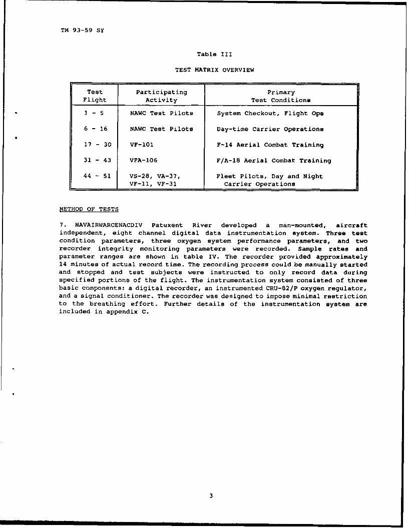
Table III
TEST MATRIX OVERVIEW
Test Participating Primary
Flight Activity Test Conditions
I - 5 NAWC Test Pilots System Checkout, Flight Ops
6 - 16 NAWC Test Pilots Day-time Carrier Operations
17 - 30 VF-101 F-14 Aerial Combat Training
31 - 43 VFA-106 F/A-18 Aerial Combat Training
44 - 51 VS-28, VA-37, Fleet Pilots, Day and NightVF-11, VF-31 Carrier Operations
METHOD OF TESTS
7. NAVAIRWARCENACDIV Patuxent River developed a man-mounted, aircraftindependent, eight channel digital data instrumentation system. Three testcondition parameters, three oxygen system performance parameters, and tworecorder integrity monitoring parameters were recorded. Sample rates andparameter ranges are shown in table IV. The recorder provided approximately14 minutes of actual record time. The recording process could be manually startedand stopped and test subjects were instructed to only record data duringspecified portions of the flight. The instrumentation system consisted of threebasic components: a digital recorder, an instrumented CRU-82/P oxygen regulator,and a signal conditioner. The recorder was designed to impose minimal restrictionto the breathing effort. Further details of the instrumentation system areincluded in appendix C.
3

TM 93-59 SY
Tabl.- IV
RECORDED PARAMETERS
Parameter Sample Rate Range(samples/sec)
Test Condition:Forward/Aft Acceleration 5 -8 to +8 GxVertical Acceleration 5 -8 to +8 GZCabin Ambient Pressure 1 0 to 16 PSIA
Oxygen System Performance:Regulator Inlet Pressure 10 0 to 128 PSIGRegulator Outlet Flow 20 0 to 390 LPM ATPDRegulator Outlet Pressure 10 -10.0 to 15.6 in. H2 0
Recorder Integrity Monitoring:Battery Voltage 1 0 to 5 VDCSignal Conditioner Voltage 1 0 to 5 VDC
8. The data were reduced and analyzed to determine inhalation peak flow rates,breath tidal volume, and breathing rate. More recent guidance for oxygen systemperformance is provided in the OBOGS design and installation specification(reference 3) and the Air Standardization Coordinating Committee standard foraircrew breathing systetrq (reference 4). These documents required sinusoidal peakflows of 200 liters/minutes (LPM) altitude temperature, pressure, dry (ATPD). Wecompared our measured data to the recommended flow rates of reference 3 to ensurethe specification is adequate for breathing flow performance requirements.
9. Test subjects were selected at random with an effort to obtain subjects withvarying degrees of experience. Each test subject was thoroughly briefed on theobjectives of the test, the operating procedure for the recorder, and the desireddata points (operating conditions) for recording data. Subjects were freelyallowed to decline being a test subject.
10. Data were acquired during 51 flight tests using F/A-18, F-14, A-6, A-7, andS-3 aircraft. Data records were categorized into baseline and eight operationalsequences. The total number of breaths measured during each category are listedin table V.
4

TM 93-59 SY
Table V
CATEGORICAL SUMMARY
Condition Number of ContributingBreaths Subjects
All Measured Data 11266 41
System Checkout (Base Line) 137 33Ground Operations/Taxi 269 8Routine Flight Operations 4351 41
Conventional Take-Off 674 27Conventional Landing 183 8
Catapult Launch 705 15Carrier Arrested Landing 619 15
High-g/Acrobatic Maneuvering 771 8Aerial Combat Maneuvering 3557 22
Total Breaths Measured = 11266Total Contributing Aircrew Test Subjects = 41Total Test Flights = 51(Six subjects flew more than one mission)
11. The data were analyzed to determine the maximum (pnak) oxygen flow duringinhalation (LPM, ATPD), the breathing rate in breaths per minute (BPM), and thetidal volume exchange in liters for each breath. These parameters are illustratedin figure 1 for sinusoidal breathing. For each category, the data contributed byeach aircrewman were normalized to evenly weight each contributor and not biasthe data by any single individual.
5

TM 93-59 SY
Inhialati on 250
200 -- ----- Peak Isplirw atory Flow lste
150-
Tidal Volume
100-
50-
lu. 0- I I IME C SEC)00o 0.2 o.4 O.6 0.8 1, 1.2 1.4 1.6 1,8 Ia 2.2
-50 I
4L -100
-150 I
-200l-eath Duration Cec) 1--
Exhalatlon -250
Beathng 60 Breaths
Rate Weath Ouratlon Minute
Figure 1SINUSODAL BREATHING AT
200 LP4 PEAK FLOW, 30 BPM FREQUENCY
RESULTS AND DISCUSSION
OVERALL DATA TREND
12. The peak inspiratory flow data for each operational condition were analyzedstatistically. Histograms of the data distribution for each condition areprovided in appendix D. For each category, the data distributions were comparedto normal (Gaussian) and lognormal theoretical distrioutions based on themeasured mean and standard deviation. We found that a lognormal statisticaldistribution provided the best fit for the peak flow data distributions, basedon minimizing the error between the theoretical expected frequency of occurrencesand actual measured data. Table VI provides a summary of inspiratory peak flowmean and standard deviation calculated for each of the operating conditions. Thetable also provides the peak flow required to satisfy 90% and 98% of the expectedoccurrences based on a lognormal distribution. Generally, at least 98% of allpeak flows measured (see table VI and figure 1 of appendix D) for this programwere within the 200 LPM design guide. The data were then reduced and analyzed fora more detailed evaluation during specific ground and flight operatingconditions.
6

TM 93-59 SY
Table VI
PEAK FLOW RATE STATISTICAL ANALYSIS 1
Conditio,, Mean STD DEV 90% 98%(LPM) (LPM) Level 2 Level 2
(ATPD) (ATPD) (LPM) (LPM)(ATPD) (ATPD)
All Measured Data 92 38 143 197
System Checkout (Base Line) 80 39 133 193Ground Operations/Taxi 59 17 82 102Routine in-Flight Operations 78 25 112 143
Conventional Take-Off 73 2. 104 133Conventional Landing 74 36 123 178
Catapult Launch 80 26 115 148Carrier Arrested Landing 76 25 110 141
High-g/Acrobatic Maneuvering 76 23 107 135Aerial Combat Maneuvering:
All Data Acquired 125 38 176 223ACM Subject 123 172 28 209 237ACM Subject #43 186 44 245 294
IData are presented in volumetric liters per minute (LPM ATPD) and are altitudeindependent. Actual mass flow will vary with altitude.2Based on a lognormal distribution.
ROUTINE GROUND AND FLIGHT OPERATIONS
13. For routine ground operations (figures 2 and 3 of appendix D), routine flightoperations (figure 4 of appendix D), and land-based take-off and landing(figures 5 and 6 of appendix D), at least 98% of the expected occurrences werewithin the current 200 LPM peak flow requirement. We conciude that the 200 LPMpeak flow requirement defined by MIL-D-85520 (reference 3) is adequate forroutine ground and flight operations as well as land-based take-offs andlandings.
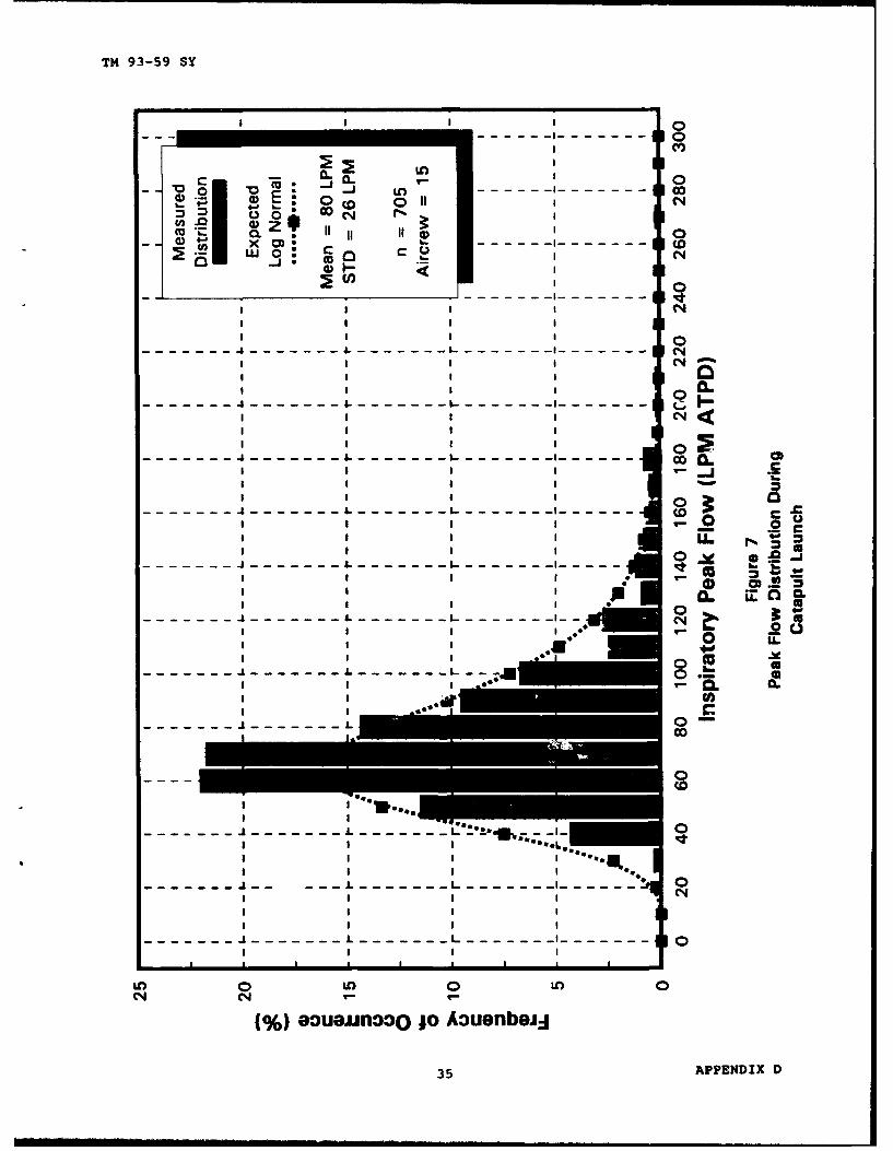
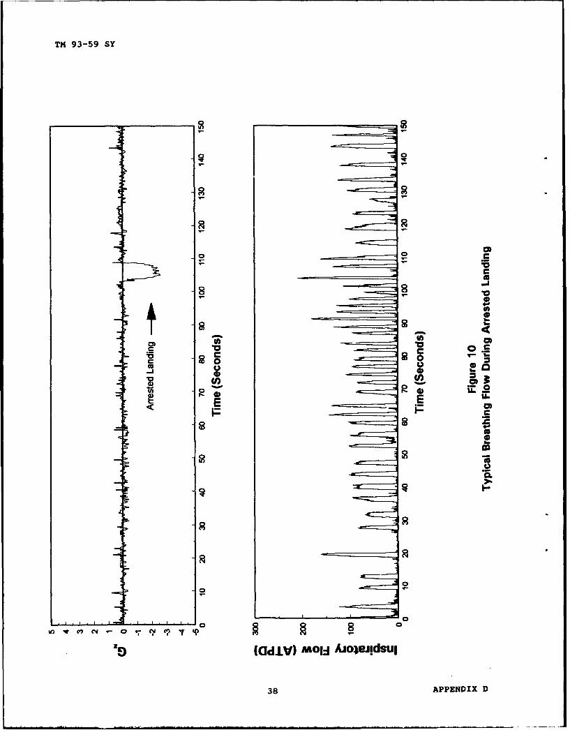
14. Breathing data measured during carrier launch and recovery were acquiredusing NAVAIRWARCENACDIV Patuxent River test pilots (day operations) and fleetpilots (both day and night operations). Results are provided in figures 7 and 8of appendix D. Typical breathing patterns for catapult launch and arrestedrecovery are also shown in figures 9 and 10 of appendix D. For both events, mostaircrew experienced slightly higher peak flows just prior and immediately afterthe event. Our data indicate that most aircrew actually hold their breath duringthe actual catapult acceleration and arrested deceleration. The high peak flowrates we measured during catapult launch and arrested recovery operations weregenerally less than 200 LPM peak flow. We conclude that the 200 LPX peak flowrequirement defined by MIL-D-85520 (reference 3) is adequate for routine day andnight carrier operations. Because testing was generally conducted in fair weatherconditions, the data may not be representative of flow rates that would be seen
7
TM 93-59 SY
during inclement weather operations. We recommend that additional in-flightbreathing data be acquired during night carrier operations in adverse weatherconditions.
HIGH-G/ACROBATIC MANEUVERING NOT INCLUDING AERIAL COMBAT MANZL".ERING
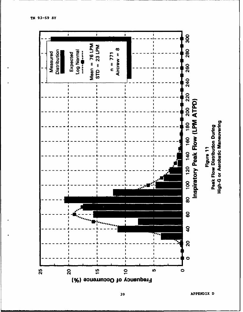
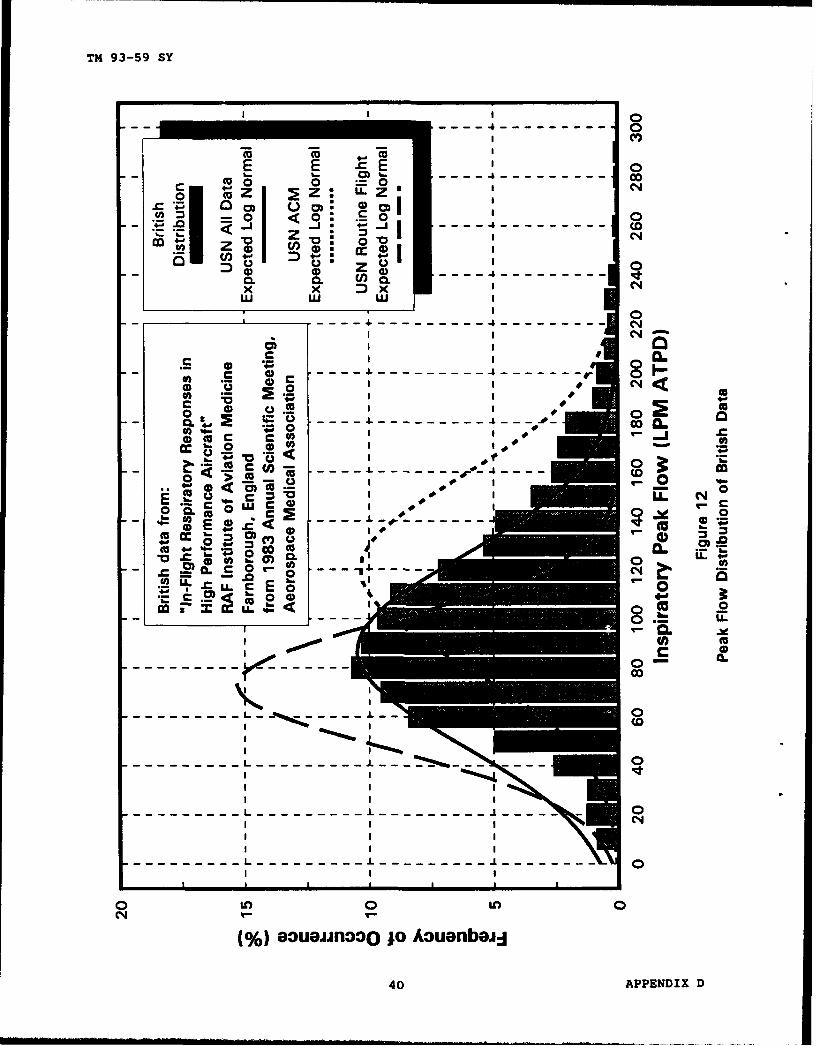
1V. Breathing data measured during high-g maneuvers (turns, rolls, aerobatics,etc.) are shown in figure 11 of appendix D. The data show reasonable agreementwith British Royal Air Force data (reference 5) as shown in figure 12 ofappendix D. Previous studies of aircrew breathing efforts (including reference 5)attempted to simulate aerial combat maneuvering (ACM) conditions by having thetest subject perform high-g aerobatics. However, results from this projectindicate that test subjects performing high-g turns and high-g aerobatics (notassociated with ACM) demonstrated lower peak flow rates than subjects engaged inACM (see discussion in next section). The data suggest that performing high-gaerobatics in a benign environment is not as physically or psychologicallydemanding as performing ACM. Because of its competitive nature, a subject engagedin ACM is more likely to push himself to his physical limits and thus producehigher breathing flow rates. The 200 LPM peak flow requirement of MIL-D-85520(reference 3) is adequate for high-g aerobatics. However, high-g aerobaticscannot be used to induce breathing rates comparable to ACM situations asdiscussed in the next section.
AERIAL COMBAT MANEUVERING
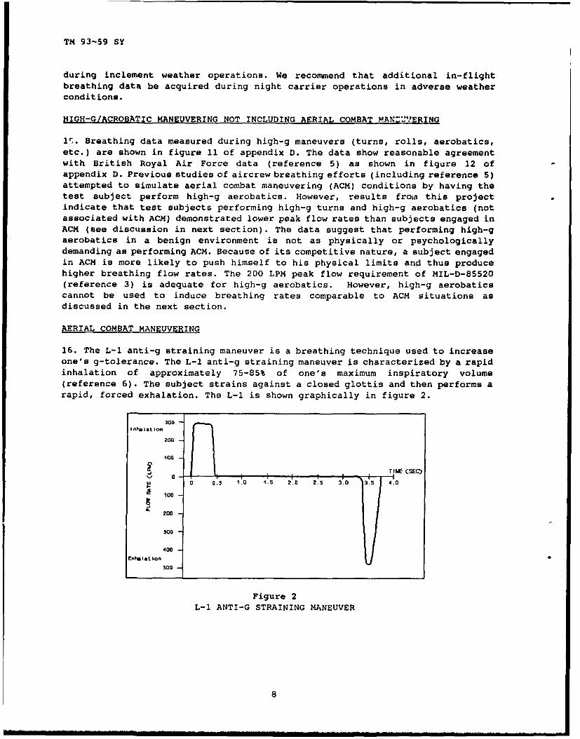
16. The L-l anti-g straining maneuver is a breathing technique used to increaseone's g-tolerance. The L-1 anti-g straining maneuver is characterized by a rapidinhalation of approximately 75-85% of one's maximum inspiratory volume(reference 6). The subject strains against a closed glottis and then performs arapid, forced exhalation. The L-1 is shown graphically in figure 2.
300 -i nllasat ion
200 -
'100
•Tk•E (SEO
0 o.s 1.0 1.5 2.0 2.5 3.0 3.5 4.0
100
S200
300
400
lxh o I at Ion500
Figure 2L-1 ANTI-G STRAINING MANEUVER
8

TM 93-59 SY
17. ACM was simulated during training exercises with VF-101 and VFA-106.Breathing data were collected over the entire ACM engagement from the set-up andapproach to the post-engagement departure. Typical data are provided infigures 13, 14, and 15 of appendix D. In order to increase his g-tolerance, thepilot will often perform several L-1 anti-g straining maneuvers prior to pullinghigh-g's (figure 13 of appendix D). Once the aircraft is at a high g-level, thebreathing peak flow often decreases possibly due to the acceleration forces onthe pilot's lungs and diaphragm. High peak flow rates in excess of 200 LPM arecommonly seen immediately following a high-g maneuver as the pilot recovers withrapid, heavy breathing (figure 14 of appendix D). Although this recovery periodmay last for several minutes following the ACM engagement, the high peak flowrates generally subside within the first 30 seconds to 1 minute. An elevatedbreathing rate with lower peak flow rates may ensue for several minutes followingthe encounter before subsiding to a normal rate (figure 15 of appendix D). Theresults from data measured during ACM indicate that high peak flow rates (inexcess of 200 LPM peak flow) may occur before, during, and/or after an ACMengagement.
18. A composite histogram of ACM data from the 22 contributing aircrew isprovided in figure 16 of appendix D. Comparing the ACM distribution to the high-gaerobatics (figure 11 of appendix D) indicates that ACM produces significantlyhigher breathing flow rates than high-g aerobatics. This was attributed to themore physically and psychologically demanding nature of ACM as discussed inparagraph 15. Previous test and evaluation methods have used high-g aerobaticsto simulate ACM. Our data, however, verifies that high-g derobatics in a benignenvironment do not produce the breathing flow rates comparable to ACM in acompetitive environment. (Note the distinct differences in the r£ak flowdistributions overlaid in figure 12 of appendix D.) We conclude that usinghigh-g aerobatics to induce breathing rates comparable to ACM situations is nota valid test and evaluation method.
19. Statistical analysis of the ACM data indicates that 200 LPM peak flow ismarginally adequate (figure 16 of appendix D) and will satisfy approximately95.5% of the expected observations. However, peak flow rates in excess of 200 LPMoccur in short "bursts" throughout the ACM engagement. These bursts are a smallportion of the entire ACM engagement and tend to become lost (statisticallyinsignificant) when analyzed over the entire ACM engagement (including the set-upand recovery periods, etc.). The tendency to perform statistical analysis on thebreathing flow rate data acquired throughout the ACM engagement could lead to theconclusion that the current 200 LPM peak flow requirement is adequate for aircrewflying ACM. Such an analysis, however, would lead to a design standard that isinadequate for the short bursts of high peak flow associated with ACMengagements.
20. Data from two individuals who actively performed anti-g straining maneuverswere given previously in table VI and are shown in figures 17 and 18 ofappendix D. These two individuals, who actively perform L-1 anti-g strainingmaneuvers, frequently produce peak flows that exceed the 200 LPM peak flowrecommended by MIL-D-85520. This result is in agreement with breathing flow ratedata acquired with NAVAIRWARCENACDIV Warminster's Dynamic Flight Simulator(reference 7), which indicates that a peak flow of 288 LPM ATPD is required toperform the L-1 anti-g straining maneuver (a "coached" L-1 maneuver in a flightsimulator). Based on the flow rate data measured during ACM training
9

TM 93-59 SY
and the centrifuge data of reference 7, we conclude that the current 200 LPN peakflow requirement of MIL-D-85520 (reference 3) is inadequate for tactical aircraftperforming high-g ACM and needs to be increased.
AIRCRAFT OXYGEN SYSTEM DESIGN
21. Oxygen system test and evaluation requires a consistent and repeatable methodfor evaluating the response of the system to a dynamic breathing load. The datapresented indicate that the highest inspiratory peak flow rates are incurredduring ACM. Oxygen systems installed in tactical aircraft should be capable ofproviding the L-1 anti-g straining maneuver continuously for the duration of thehigh-g portion of the ACM encounter.
22. The xygen system must also accommodate the rapid breathing rates and highinspiratory flow rates associated with the recovery period following ACM. Thebreathing pattern is characterized by variable amplitude inhalation pulses thatrange from 70 to 300 LPM. Duplicating this pattern on the ground for test andevaluation purposes would require breath by breath control of a mechanicalbreathing simulator. Although this is possible, it would not be repeatable oreasily duplicated from one test activity to another. A sinusoidal wave form isuniversally understood and easily reproduced. Specifying a sinusoidal flow rateof 260 LPM at sea level conditions would provide the peak inspiratory dynamicsto accommodate aircrew performing ACM at altitude. (When adjusted for altitude,260 LPM peak flow at sea level will provide in excess of 300 LPM peak flow ataltitudes above 4,000 feet.) Specifying an associated breathing rate of 43breaths per minute provides a tidal volume exchange of approximately 1.9 liters,which is not an unrealistic exchange based on the NAVAIRWARCENACDIV WarminsterL-1 profile (figure 2). Therefore, for oxygen system design, test, andevaluation, we recommend that MIL-D-85520 be changed to require tactical aircraftoxygen systems be capable of delivering a 260 LPM peak inspiratory flow rate at43 breaths per minute for a minimum of 3 minutes.
OXYGEN SYSTEM COMPONENT DESIGN
23. Oxygen system components, such as the oxygen mask and regulator, must becapable of providing the peak flow demands experienced during ACM. Most componentspecifications either specify inadequate dynamic response conditions or none atall. Oxygen mask valves (reference 8) are required to meet steady flow conditionsof 100 LPM steady flow for inhalation, 150 LPM for dumping. CRU-79/P oxygenregulators (reference 9) are required to provide 100 LPM steady flow. Previoustesting at NAVAIRWARCENACDIV Patuxent River (reference 10) revealed substandardperformance of oxygen mask and regulator combinations under dynamic flowconditions. On numerous occasions, the oxygen mask valve would "lock up" duringexhalation. This was attributed to high pressure from the oxygen regulator (asit tried to catch up to the rapid onset flow demand) interfering with the oxygenmask valve closure during the forced exhalation period of the L-1 maneuver. Whilecollecting data for this project, discussions with aircrew confirmed numerousinstances of mask valve "lock up" in flight during heavy breathing. (Thesereports referred to their standard oxygen gear, not our instrumentation system.)Therefore, we recommend that the dynamic breathing requirements of 260 LPM peaksinusoidal flow at 43 BPM frequency be incorporated into the oxygen mask valveperformance specification (MIL-V-27296B) and the regulator specifications(MIL-R-81553A(AS) and MIL-R-85523(AS)).
10

TM 93-59 SY
ANTI-G STRAINING TECHNIQUE TRAINING
24. During pre- and post-flight interviews, the test subjects were asked if theyuse any type of anti-g straining maneuver. Responses from this informal surveyindicated that only 10% of F-14 and F/A-18 pilots participating in this programcommonly practiced an L-1 anti-g straining technique. The majority of thesubjects were only vaguely familiar with the L-1 techniques as presented duringtheir quadrennial physiology training. Many of the pilots who do not usestraining techniques stated they reduce the g-load on the aircraft when theystart to "gray out" rather than performing anti-g straining techniques. Itappears that the full benefit of the anti-g straining techniques are not realizedby a large percentage of the aircrew. This deficiency has been previouslyrecognized and centrifuge training for tactical aircrew is now required byOPNAVINST 3710.7P.
25. Interviews with test subjects during this project indicated that the aircrewexhibiting enough knowledge to adequately perform the L-1 maneuver had additionalface-to-face, one-on-one training on the techniques at some time in their career.At the time, the quadrennial physiology training program only provided a verbal(or video) presentation of the L-1 technique. There were no practice sessionsinvolved. Physiology training is currently being updated to include face-to-face,one-on-one instruction using a computer based breathing rate and characteristictraining aid. This training is a lead-in for centrifuge training. Changes to thephysiology training program, along with required centrifuge training, willgreatly improve the aircrews' awareness of anti-g straining techniques. Theincreased training will be reflected in higher demands on the oxygen system tomeet the dynamic flow requirements of anti-g straining. We recommend continuedemphasis on anti-g straining and its benefit in reducing g-induced loss ofconsciousness.
SEA LEVEL PERFORMANCE
26. Oxygen system components (i.e., oxygen masks, . 4ulators, concentrators,etc.) are mass flow limited. The human breathing system is volume limited. Fora constant volumetric demand on the oxygen system (i.e., a constant breathingrate), the mass flow through the system will decrease with altitude due to thereduced ambient air density. Thus, a system that provides adequate volumetricflow at altitude may not be adequate at low altitudes due to the increase in massflow at low altitudes.
27. Peak volumetric flow rate measurements of aircrew conducting ACM at aircraftaltitudes of 10K to 28K feet greatly exceed 200 LPM peak flow. It is unknown ifthe oxygen system design could provide these same aircrew with adequate mass flowduring low altitude ACM (S.L. to 5,000 feet). The noticeable lack of pilotcomplaints of poor dynamic performance of the aircraft's oxygen system might beattributed to the fact that the majority of ACM training is conducted at 10K to28K feet aircraft altitude. At these altitudes, the pilot's volumetric flowrequirements are the same as at sea level but his mass flow requirements aregreatly reduced by the reduced ambient air density. Ground tests on the AV-8B,TAV-8B, T-45, and F/A-18 have been used to evaluate the peak flow capability ofthe OBOGS under simulated conditions. Example data are provided in figure 19 ofappendix D. The capability of the LOX system in the F/A-18 and F-14 aircraft andthe OBOGS in the F-14 to provide the flow rates necessary for conducting ACM atlow altitude have not been quantitatively tested. Inadequate peak flow capabilityof the aircraft's oxygen system during low altitude ACM will seriously compromise
11

TM 93-59 SY
the pilot's ability to breath, to communicate (due to the high peak flow ratesassociated with speech), to perform the anti-g straining maneuver, and toultimrately perform ACM. We recommend that a dynamic breathing performance testof the F-14 aircraft OBOGS and the F-14 and F/A-18 LOX systems be performed todetermine the maximum peak flow capability of these systems at sea levelconditions.
TIDAL VOLUME/BPM ANALYSIS
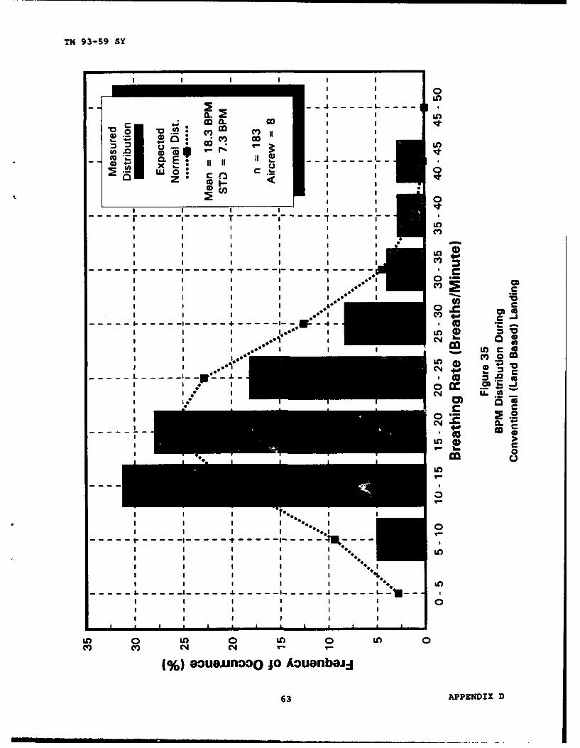
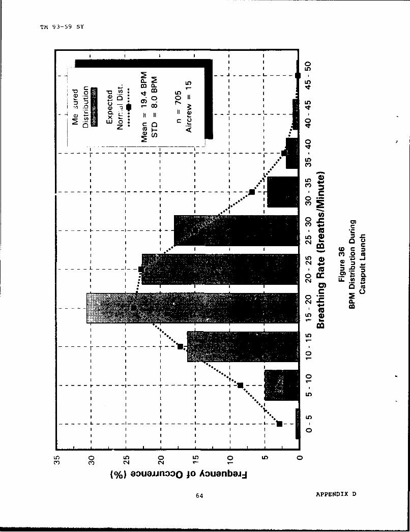
28. The data were reduced to determine tidal volume and BPM distributions asdescribed in paragraph 11. For completeness, histograms of the tidal volumedistributions are found in appendix D, figures 20 through 29, while BPMdistributions are in appendix D, figures 30 through 39. A statistical analysisindicates that, while tidal volume is best modeled by a lognormal distribution,BPM is best modeled by a normal distribution. The calculated mean and standarddeviation for each category is summarized in table VII. Although notsignificantly different, the data do show a trend of increasing tidal volume andBPM with increasing workload from ground operations to flight operations, carrierlaunch and recovery, high-g maneuvering, and ACM. Not evident within thestatistical averages are the typical exaggerated breaths measured immediatelyprior to catapult launch (figure 9 of appendix D) and carrier arrested landing(figure 10 of appendix D). These breaths tended to be deeper and slower thannormal. These breaths are typically of low peak flow amplitude and should thusbe satisfied by the ACM required peak flow rates.
12

TM 93-59 SY
Table VII
TIDAL VOLUME AND BPM BY CATEGORY
Tidal Volume(Liters)
Conditions No. No. Mean STD 90% 98%Obs. Air- DEV Level1 Level1
crew
All Measured Data 11266 41 1.47 0.82 2.57 3.95
System Check (Base Line) 137 33 1.89 0.98 3.21 4.78Ground Operations/Taxi 269 8 1.18 0.48 1.83 2.50Routine In-Flight Operations 4351 44 1.49 0.80 2.56 3.88
Conventional Take-Off 674 27 1.63 0.91 2.85 4.38Conventional Landing 183 8 1.14 0.54 1.87 2.69
Catapult Launch 705 15 1.36 0.69 2.29 3.38Carrier Arrested Landing 619 15 1.41 1.03 2.75 4.83
High-g Acrobatic Maneuvering 771 8 1.17 0.64 2.03 3.09Aerial Combat Maneuvering 3557 22 1.96 0.92 3.20 4.60
'Based on a lognormal distribution.
Breaths Per Minute
Conditions No. No. Mean STD 90% 98%Obs. Air- DEV Level1 Level1
crew
All Measured Data 11266 41 20.4 9.8 32.9 40.5
System Check (Base Line) 137 33 14.5 5.7 21.8 26.2Ground Operations/"axi 269 8 17.0 5.6 24.2 28.5Routine In-Flight lpkrptions 4351 44 17.5 7.9 27.6 33.7
Conventional Take-Off I74 27 15.6 8.7 26.7 33.4Conventional Landing i83 8 18.3 7.3 27.6 33.3
Catapult Launch 705 15 19.4 8.0 29.6 35.8Carrier Arrested Landing 619 15 20.7 7.9 30.8 36.9
High-g Acrobatic Maneuvering 771 8 24.4 10.2 37.5 45.3Aerial Combat Maneuvering 3557 22 21.6 11.6 36.5 45.4
1Based on a normal distribution.
13

TM 93-59 SY
THIS PAGE INTENTIONALLY LEFT BLANK
14

TM 93-59 SY
CONCLUSIONS
29. The data collected for this project generally show good correlation withprevious studies. The data base provides unique results for carrier operationsand ACM conditions not previously reported.
30. The breathing requirement specifications for LOX and OBOGS equipped aircraftare inadequate for breathing rates measured during high workload ACM in tacticalaircraft.
SPECIFIC
31. The 200 LPM peak flow requirement defined by MIL-D-85520 (reference 3) isadequate for routine ground and flight operations as well as land-based take-of fsand landings (paragraph 13).
32. The 200 LPM peak flow requirement defined by MIL-D-85520 (reference 3) isadequate for routine day and night carrier operations (paragraph 14).
33. The 200 LPM peak flow requirement of MIL-D-85520 (reference 3) is adequatefor high-g aerobatics (paragraph 15).
34. High peak flow rates (in excess of 200 LPM peak flow) may occur before,during, and/or after an ACM engagement (paragraph 17).
35. Using high-g aerobatics to induce breathing rates comparable to ACMsituations is not a valid test and evaluation method (paragraph 18).
36. The current 200 LPM peak flow requirement of MIL-D-85520 (reference 3) isinadequate for tactical aircraft performing high-g ACM (paragraph 20).
37. Changes to the physiology training program, along with required centrifugetraining, will greatly improve the aircrews" awareness of anti-g strainingtechniques. The increased training will be reflected in higher demands on theoxygen system to meet the dynamic flow requirements of anti-g straining(paragraph 25).
RECOMMENDATIONS
38. Acquire additional in-flight breathing data during night carrier operationsin adverse weather conditions (paragraph 14).
39. Install tactical aircraft oxygen systems that are capable of providing theL-1 anti-g straining maneuver continuously for the duration of the high-g portionof the ACM encounter (paragraph 21).
40. Change MIL-D-85520 to require tactical aircraft oxygen systems to be capableof delivering a 260 LPM peak inspiratory flow rate at 43 breaths per minute fora minimum of 3 minutes (paragraph 22).
15

TM 93-59 SY
41. Incorporate the dynamic breathing requirements of 260 LPM peak sinusoidalflow at 43 BPM frequency into the oxygen mask valve specification (MIL-V-27296B)and the regulator specifications (MIL-R-81553A(AS) and MIL-R-85523(AS))(paragraph 23).
42. The anti-g straining technique and its benefit in reducing g-induced loss ofconsciousness should continue to be emphasized through quadrennial physiologytraining and mandatory centrifuge training for TACAIR aircrew (paragraph 25).
43. Perform a dynamic breathing performance test of the F-14 aircraft OBOGS andthe F-14 and F/A-18 LOX systems to determine the maximum peak flow capability ofthese systems at sea level conditions (paragraph 27).
16

TM 93-59 SY
REFERENCES
1. AIRTASK A531531A/053-D/6W06060000, WUA A-5311B-R6, of 5 Sep 1985.
2. NAVAIRWARCENACDIV Warminster WUA N62269/93/WX/0006 of 3 Dec 1992.
3. Military Specification MIL-D-85520, Design and Installation of On BoardOxygen Generating Systems in Aircraft, General Specification for, of 10 Mar1983.
4. ASCC AIR STD 61/22, Air Standardization Coordinating Committee, of 18 Aug1982.
5. "In-flight Breathing Responses in High Performance Aircraft", 1983 AnnualScientific Meeting, Aerospace Medical Association, 23-26 May 1983.
6. "Effect of Inspiratory Volume on Intrathoracic Pressure Generated by an L-1Maneuver", Aviation, Space, and Environmental Medicine, Nov 1986.
7. "F/A-18 Breathing System Analysis, Phase II - Breathing RequirementsEvaluation", NAVAIRDEVCEN Report 0 NADC-87061-60 (not formally released,information provided by NAVAIRWARCENACDIV Warminster Code 6023).
8. Military Specification MIL-V-27296B, Valve, Oxygen Mask, CombinationInhalation and Exhalation, of 25 Jul 1983.
9. Military Specification MIL-R-81553A(AS), Regulator, Chest Mounted,100 Percent Oxygen, Positive Pressure, CRU-79/P, of 16 Jul 1990.
10. NAVAIRTESTCEN Technical Report SY-74R-87, "F/A-18A High-G Loss ofConsciousness Oxygen System Component Evaluation", of 24 May 1988.
17

TM 93-59 SY
THIS PAGE INTENTIONALLY LEFT BLANK
18

TM 93-59 SY
DATA CATEGORY DESCRIPTION
Category Description
System Checkout (Base Line) Once the test subject was situated in theaircraft and the final connections made, thesubject was asked to take one short record (2 or3 breaths) to confitm operation of the recorderand breathing gas system. Test subjectsgenerally took slow, deep, exaggerated breathsto get a feel for the response of the syster.
Ground Operations/Taxi Data acquired during taxi and other groundoperations that do not include take-off orlanding rolls.
Routine In-Flight Operations Test subjects performing routine in-flightoperations such as navigation, formation flying,idle powe•. descents, etc.
Conventional Take-Off Test subjects were instructed to start recordjust prior to take-off roll and to stop recordapproximately 30 seconds after take-off. Theserecords are normally 45 to 60 seconds induration.
Conventional Landing Test subjects performing land based landings.
Catapult Launch Test subjects were instructed to start recordapproximately 15 seconds prior to launch and tostop record approximately 20 to 30 seconds afterbecoming airborne.
Carrier Arrested Landing Test subjects performing carrier landings duringboth day and night operations.
High-g Maneuvering Test subjects performing airborne maneuvers inexcess of 3-g or aerobatics. This categoryincludes hard turns and "breaks" but does notinclude maneuvers during aerial combatmaneuvering.
Aerial Combat Maneuvering Data acquired during ACM training exercises. ACMincludes IV1, 2V1, 1V2, and 2V2 situations. OnlyACM data at elevated g-levels were accepted inthis category.
19 APPENDIX A

TN 93-59 SY
THIS PAGE INTENTIONALLY LEFT BLANK
20

TM 93-59 SY
TEST MATRIX SUMMARY
Aircraft ExperienceFlight Type Aircrew Level Flight Summary
1 F/A-18A Pilot TP 6 Catapults (land based)2 A-7 Pilot TP Bombing runs, high-g maneuvering3 A-6 B/N TP Bombing runs, ship attack4 A-7 Pilot TP catapult (land based), FCLP's5 A-7 Pilot TP High-g maneuvers, aerobatics
Carrier Launch and Recovery. Day-Time. USS ROOSEVELT (CVN-71.
6 F/A-16 Pilot TP 1 catapult, I trap7 A-7 Pilot TP 2 catapults, 2 traps8 F-14 Pilot TP 1 catapult9 F-14 Pilot TP 2 -atapults, high-g turns10 A-6 Pilot TP 1 catapult, 1 trap, 2 wave offs11 A-6 Pilot TP 2 touch & go, 1 trap, high-g12 F/A-18 Pilot TP 1 trap13 F/A-18 Pilot TP 1 catapult, 1 trap, high-g turns14 F-14 Pilot TP 4 catapults, 4 traps15 F-14 NFO TP 2 catapults, 3 traps16 F-14 NFO F-EX 2 catapults, 2 traps, 2 high-g turns
F-14 Aerial Combat Training, NAS Key West. VF-101
17 F-14 Pilot F-IP gunnery run, air intercept18 F-14 Pilot F-IP high-g turns, aerobatics, ACM demo19 F-14 Pilot F-IPT (3) 1 v 1 ACM20 F-14 Pilot F-SP (3) 1 v 1 ACM21 F-14 Pilot F-SP,T (2) 1 v 1 ACM, high-g turns22 F-14 NFO F-SN (3) 2 v 2 ACM23 F-14 Pilot F-SP,T (1) 1 v 1 ACM24 F-14 Pilot F-SP (4) 1 v 1 ACM25 F-14 Pilot F-SP (1) 1 v 1 ACM26 F-14 Pilot F-SP (3) 1 v 1 ACM27 F-14 NFO F-SN Straight & Level Flight28 F-14 NFO F-SN (1) 1 v 1 ACM29 F-14 Pilot F-IP (1) 1 v 1 ACM30 F-14 NFO F-SN (3) 1 v 1 ACM
21 APPENDIX B

TM 93-59 SY
F/A-18A Aerial Combat Trainina. NAS Key West, VFA-106
31 F/A-18 Pilot F-IP (2) 1 v 1, (1) 1 v I v 1 ACM32 F/A-18 Pilot F-IP (4) 2 v I ACM33 F/A-18 Pilot F-IP (1) 1 v 1 ACM34 F/A-18 Pilot F-IP (4) 2 v 2 ACM35 F/A-18 Pilot F-IP (4) 1 v 1 ACM36 F/A-18 Pilot F-IP (2) 2 v 2 ACM37 F/A-18 Pilot F-SP (3) 2 v 2 ACM38 F/A-18 Pilot F-SP (3) 2 v 2 ACM39 F/A-18 Pilot F-IP (2) 2 v 2, (1) 1 v 1 ACM40 F/A-18 Pilot F-SP,T (3) 2 v 2 ACM41 F/A-18 Pilot F-SP,T (3) 2 v 2 ACM42 F/A-18 Pilot F-SP Straight & Level Flight43 F/A-18 Pilot F-SP (1) 1 v 1 ACM
Fleet Aircrew. Carrier Launch and Recovery. USS SARATOGA (CV-60)
44 s-3 NFO F-EX 2 catapults, 2 traps, Night CQ45 F-14 Pilot F-NP 4 catapults, 4 traps, Day 0Q46 F-14 Pilot F-EX 4 catapults, 2 traps, Night CQ47 A-7 Pilot F-EX 2 air intercepts48 F-14 Pilot F-EX 3 catapults, 3 traps, Day CQ49 s-3 Pilot F-NP luw altitude surface search at night50 A-7 Pilot F-NP 3 catapults, 5 traps, Day CQ51 F-14 Pilot F-NP 2 ACM passes, 3 bolters poor weather
Experience Level:TP: Test Pilot - U.S. Navy Test Pilot School graduate, well
experienced in aircraft typeF-EX: Fleet Aircrew - well experienced in aircraft typeF-IP: Fleet Aircrew - Instructor Pilot, well experienced in aircraft
typeF-IPT: Fleet Aircrew - Instructor Pilot in Training, well experienced in
typeF-SP: Fleet Aircrew - Student Pilot, limited experience in aircraft typeF-SP,T: Fleet Aircrew - Student Pilot, Transitioning from other aircraft
typeF-SN: Fleet Aircrew - Student NFO, limited experience in aircraft typeF-NP: Fleet Aircrew - New Pilot, new pilot in squadron, limited time in
aircraft type
22 APPENDIX 8

TM 93-59 SY
INSTRUMENTATION SYSTEM
SYSTEM
1. The instrumentation system used to acquire breathing and aircraft positionaldata is a man-mounted, aircraft independent, battery operated, eight channel,programmable, digital recorder with an instrumented CRU-82/P oxygen regulator andassociated signal conditioner. The components are shown in figure 1.
RECORDER
2. The digital data recorder included a Z-80 microprocessor, analog to digitalconverter, 16 character alpha-numeric keypad, and 24 character by 3 line liquidcrystal display for user queuing and prompting instructions. Sampling rates couldbe varied from 1 to 200 samples/second/channel. With power on, the record processcould be started and stopped to conserve memory for the desired test point. Therecorder was later modified with a raised toggle switch to facilitate recordstarting and stopping during night operation. The recorder was uploaded with testidentification information and channel sampling requirements using a personaltype computer. Postflight data were downloaded, reduced, and analyzed using thesame computer. The recorder was worn on the aircrew's left thigh and held inplace with two standard knee-board straps and an additional strain relief strapthat looped through the aircrew's torso harness for added stability duringwalking (preflight) and carrier arrested landing.
INSTRUMENTED REGULATOR
3. The CRU-82/P oxygen regulator was designed for use with the OBOGS but mayalso be used on aircraft with LOX systems. The CRU-82/P exhibits superior flowcharacteristics and is capable of sustaining a positive outlet pressure duringsinusoidal peak flow rates in excess of 450 LPM. The objective of theinstrumentation system was to measure unrestricted breathing efforts during allphases of flight. A restrictive breathing gas source would tend to reduce peakflow rates and distort flow wave forms. Breathing data measured without any typeof oxygen mask would be ideal. However, NATOPS requirements and safetyconsiderations prevented having the test subject fly above 10,000 feet withoutoxygen or with a 100% oxygen enriched cockpit. Therefore, the CRU-82/P oxygenregulator provided the best option for providing an "unrestricted" oxygen supplywithout denying the aviator oxygen breathing gas. Subsequent laboratory testing(NAVAIRWARCENACDIV Patuxent River Report SY-74R-87) evaluated the oxygen maskcavity pressure as a function of oxygen regulator outlet pressure. Results fromthat series of testing indicate that, for peak flow rates less than 390 LPM ATPD,the CRU-82/P oxygen regulator will maintain a positive pressure within theMBU-14/P oxygen mask cavity. Therefore, it can be concluded that, for peak flowrates less than 390 LPM ATPD measured in-flight, the oxygen mask cavity pressureremained positive and the test subject was provided an unrestricted oxygensource.
4. To facilitate maximum flexibility in choosing test subjects during remotesite testing, the test subject aviators were allowed to use their own personaloxygen masks. Prior to flight, the test subject's personal oxygen mask wasattached to instrumented CRU-82/P oxygen regulator and oxygen hose. The CRU-82/Pregulator was held by velcro and snaps to a cummerbund type strap that looped
23 APPENDIX C

TM 93-59 SY
through the aircrew's torso harness. This mounting retained the flexibility ofmounting the instrumented regulator to the aircrew without modifying his torsoharness.
5. The CRU-82/P oxygen regulator was instrumented with pressure transducers onthe oxygen high pressure inlet and low pressure outlet. A laminar flow elementwas modified to attach to the outlet of the regulator. The pressure drop throughthe laminar flow element was calibrated against known dynamic flows generated bya Variable Profile Breathing Simulator (VPBS). Pressure transducers were mountedperpendicular to the Gz axis to minimize the effects of positive and negativeacceleration on flow measurements.
SIGNAL CONDITIONER
6. The signal conditioner provided instrumentation supply voltage and datasignal conditioning for the system's transducer. The signal conditioner wasnormally placed in the aircrew's pistol pocket (upper left pocket on the torsoharness) or in the cavity behind the torso harness zipper.
AIRCRAFT/AIRCREW COMPATIBILITY
7. An aircrewman wearing the instrumentation system is shown in figure 2. Priorto first flight, the Aircrew Systems Escape and Survivability Section evaluatedthe instrumentation system and determined the system did not impose additionalhazards for emergency egress. Additionally, the system was measured forelectromagnetic emission. No abnormal emissions were detected and it wasdetermined that the instrumentation system would not interfere with any of theaircraft electronic equipment. Physical weight characteristics are shown below:
Component WeiahtRecorder w/knee-board straps: 1278 gramsRegulator w/cummerbund: 937 gramsSignal Conditioner w/connectors: 344 grams
Total Recording System Weight: 2559 grams
CRU-79/P Regulator w/case: 371 grams
Delta Weight Growth for Recording System: 2188 grams (4.8 lb)
24 APPENDIX C

TM 93-S9 SY.
-mcc0~0
z Lz2 CL Z
F-s H)Zýu
6-4
0 >0
ol z14 0
54
0'
E4
00
w5ccd
25 APPENDIX C

TM 93-59 SY
SIGNAL CONDITIONERCARRIED IN FLIGHTSUIT POCKET(NOT VISIBLE)
INSTRUMENTEDREGULATOR
PILOT'SKNEE BOARD ----
RECODR•
Figure 2PILOT WEARING INSTRUMENTATION SYSTEM
26 APPENDIX C

TM 93-59 SY
SAMPLE RESPIRATORY DATA AND HISTOGRAMS
LIST OF FIGURES
No. Figure Title
Peak Flow Data
1. Peak Flow Distribution of All Measured Data2. Peak Flow Distribution During System Checkout3. Peak Flow Distribution During Ground Operations/Taxi4. Peak Flow Distribution During Routine In-Flight Operations5. Peak Flow Distribution During Conventional (Land Based) Take Off6. Peak Flow DistriDution During Conventional (Land Based) Landing7. Peak Flow Distribution During Catapult Launcha. Peak Flow Distribution During Carrier Arrested Landing
9. Typical Breathing Flow During Catapult Launch10. Typical Breathing Flow During Arrested Landing
11. Peak Flow Distribution During High-g or Aerobatic Maneuvering12. Peak Flow Distribution of British Data13. Breathing Flow During ACM Training14. High Peak Flows Associated with ACM Recovery15. Normal Breathing Following ACM Recovery16. Peak Flow Distribution During Aerial Combat Training
17. Peak Flow Distribution During Aerial Combat Training for Subject #2318. Peak Flow Distribution During Aerial Combat Training for Subject #43
19. Breathing Performance of TAV-8B OBOGS Using Two Breathing Simulators
Tidal Volume Data
20. Tidal Volume Distribution of All Measured Data21. Tidal Volume Distribution During System Checkout22. Tidal Volume Distribution During Ground Operations/Taxi23. Tidal Volume Distribution During Routine In-Flight Operations24. Tidal Volume Distribution During Conventional (Land Based) Take Off25. Tidal Volume Distribution During Conventional (Land Based) Landing26. Tidal Volume Distribution During Catapult Launch27. Tidal Volume Distribution During Carrier Arrested Landing28. Tidal Volume Distribution During High-g or Aerobatic Maneuvering29. Tidal Volume Distribution During Aerial Combat Training
27 APPENDIX D

TM 93-59 SY
Breaths Per Minute Data
30. BPM Distribution of All Measured Data31. BPM Distribution During System Checkout32. BPM Distribution During Ground Operations/Taxi33. BPM Distribution During Routine In-Flight Operations34. BPM Distribution During Conventional (Land Based) Take Off35. BPM Distribution During Conventional (Land Based) Landing36. BPM Distribution During Catapult Launch37. BPM Distribution During Carrier Arrested Landing38. BPM Distribution During High-g or Aerobatic Maneuvering39. BPM Distribution During Aerial Combat Training
28 APPENDIX D

T1 93-59 SY
gI I
DI I
C - 4
-~~~ -~ --C4e JCD
4-,-C -~ - " -N
4. - - - o I
( fl aI I I I N
Uu -Z l -i - , - .b.
'D I I I I
III I I Co(
I I) I I I
III I II I BI I B
M N2
I I I I I "a
III I I I BN•
I I I I I 0I I I IiI
CD0.
00
I- I ..4,,4
IBI I I
00
I I II
0BI I B
B I , ,,. ' a
CCL
00
a II
I I I I I B
W, "C"(14 0 co co qt" 04 0
1eoueImooO jo Bouenbe-I B
29 APPlENDIX D

TH 93-59 SY
I I I0
SC ,,CL CL)4 -- - - - - "E o , ccn m 11
(j O* !
az lii l, I
SI I f
II I
I I I
' ' - -SI
I I I * ,u
00
EI 04.0
L--- -- -- --------- ------I-------------------4
C o0. o
I 0
- -- - - - - -- L-- -- ---------- ---------------------- ------ I-4
0 Mn 0
S- -- ---
CL
--------- 0
0w0 AED0
N0
30 APPENDIX0

TN 93-59 SY
I I I I I t
-- -M , 1
- 0 4 --• --• -I 0
- I z1-4 - - - - --4I - -- -
C4ai.Eo c 0
- - -- - - - 4 - - - -- - ,4 - - - - . .. . .- -
-U III
-- - -- -- --- - - - -- - --- - B--- - 8 lsI I I (
BII I B
-B-------1------- -------------- ------ 4------ I--------0--C-- mI II I(..
I t I I •
I I I I
II B I B ,
BI I I I O
0• A
CL M 0 0
-.. 0
I~j I - 0
O BO I In
(1eauaunooo jo A~ouenbeJ4j
31 APPENDIX D

TH 93-59 SY
III0
--I- i
CC#
CL !0. i 0WL 09 : C14 .
I ISI I ,-0
01AI I I•
?t 0 0I I I w
0 S
IIIIi
I A
-- - L 0
I I I0
0
6~~~ 0
14.
II I I II- A-------------L------------- L -- - - 0-- -
O 0 Ln 0 U' 0(N (N 1- ,
%) eouuiJnooo jo Aouanboj-j
32 APPENDIX D

TM 93-59 SY
cc - I:I cvn
SII I
! -
- - I 0- -
(0
--
I I I I-0
0 0
SS at00w 0
I I I .0 €
Il I I- •. e
I I I'" II- •
,I III I.0 0
II I I
II I I f*h'
II I I - - -
I I I 0 1[.2
' I I I I 0
Cc aL - - - - - ----- ---
00
co
- 0 L Ln u 0N •N --
1e OUeuno00 jo Aouenbejl4
33 APPENDIX D

TM 93-59 SY
I I Ii
m. __j 0"GO,--! * N
0 0 --- --- - -, -,i o
I N
II I
x D. -- -- I- ---- -- - c
4 0
I I '
-4-------- - - --------- ------- - ,- -------.- ,--- - ----
II I o
II I "' " "" " "I,
0
a a
II I Il LL .. ,.%,% ,0 x
II II
U. i0.
IIII I III
0 c
goCI >
5ja- - - - - -- - - - - - i
N I-
1%1 oouojjnooo jo Aouenboj-
34 APPENDIX D
TM 93-59 SY
a a a a 0- 00 0
V f -' °---
-a) -o- o
:-I
L_ ,0 Co CI t -
4 -- -- ----- -_-1------- =- W
I I a a
I I I I 0,
I I I I Iu "
-. 4- - - - -..------------------- -- I----------"---,-=-
I I I I I- •
a-------------- aU 0c
.02
I a I I *'
0 C
C4
0
- -, ----L ------------ - -. co • C.
0
. 0
(IoCo
S.---- --- ---- 0.... -
IC a4
(%soueuinooo jo Aouenbe,=l
35 APPENDIX D

TM 93-59 SY
0- 0
I 0- 0
i~Z t III
I I I
0 -1 - 0.• -- -- - - - - - - - --- co
I I 0 ,.
II II 0
0~
I II
_4 04
CD 0
II I
iI I S - .- I o o •
- - --, ----------------- - C14
4C 4
SI I._ = ,.
0~
-- -I -L - - I . . .-O - - - -
0
I I
-- L 0 -
0 °
-- -.--- - - - - - - - - -,- - - sJ
CcI
0 (L il 0
0 In 0 In 0
(%) eouei~nooO ;o Aouenbeij
36 APPENDIX D

TM 93-59 SY
oc
c
CLC
m0 0
2 (GdLV) oL-jAjop~dsu
37 APNIX D
TM 93-59 SY
0 0
E ~U.
38 APENI -D
TM 93-59 SY
IIqI I I I 8
!-
Ii ,0 00
I . I I I~
I I
I I I I (q
I I I I0. . - ---------- -----
I I I I {II I I a
I I I II I- I- -I- -
I I I I
''I I .5.•/I I I I 4
I I I I a
I I I I IL---------------------- L---,---m------------------
iL
I I I '"
C4
I I I I
L CL c
IN N%) eu o o AuounboJ.
39 APPENDIX D
TM 93-59 SY
E 0
c 0 -0
-I ._ OI --- ------------.E E,
004
I I
t- s~~- . - -.. . .- - - - - c
S o I I0
I I I "4'
0 I z I I
r- cm 0 C
II gI0
:3 0 I S-oo
I ~I I I I&:
O 'o "0 0.q
U) z 0) Cl 0C
40 U z NDIX D
(I~ 'U
0---- - - - ---- - - - --r 'CS
-- - - - ----- ------ I h 0 - - - 4
I cc
Ip 0
M I-
0 >f 0 0
40 APPENDIX

TM 93-59 SY
CDC
17L1Ad.
co-
V V
o 0
0 4D
4).
E E 0
cot
M 0 r 0 0 M N0
z (a .LV) MOM AJOM dsu
41 APPNDIX

TH 93-59 SY
VS
00U)U
00
E 0
cc 4
0 0)Go P- 0 n V q N C40O
z ((]JLV)MOIJ jole~dsu
42 APPENIX

TM 93-59 SY
0
U)U
0
U) dLV MO U)idu
43 APEMILXcD

TM 93-59 SY
I I
ci I 00 m -j rC -------- cC1
! !
0 CO) i i0 Z 0- . 1-4 - - - --
IIII I
wo c
-II I0
*544
I I i ILL_
I I I I
4C
-- -L - - - L - 0
- -.... -. m - - -- - -- -
',j ,"S
C/ SO is0
U
I ~~~ I 4
I I Io
J - - - -L - - - -J - - - -L - - -I I I I
I I I II I I I I
1%) ouejjooo 1o /Louanbei:d
44 APPlEND IX D

TH 93-59 SY
- CI 0V~ - --- - - O
ua 0 6. :I II, c
- - CL
a: c lII-J -U; -----C4
I I 4
j I
-4--
U..,-0
u- E'0
I I I L
- -L L -
I IcI
In I In
Ioejno Io I:unb
- .L-----------------

TM 93-59 SY
- I (0
0
0.4
oC
U O r. %-
- L 0
000 c
I IL
c -o 'i I"a~ 0 -1 J -0 -J -~ - 0
a)-- Eh.c. ýtaI
(D zI 3.
C4 00 W 0
46------------ APPENDIX D

TM 93-59 SY
cu
Cuj
* Is
UI W*6 J CU CL
(3 WIWI
0.4inat I Z
-v SI'-E.*d
CD I
L.c
cu
"Is, QA%- -
oi II
Ii. iv, -1t 4? 04OV 4L.a, 44
"C' zo~
4 L qC,7 Olt, 0.
0 U) J -)
I I- U)
ZrX "Cc09zf ( i 'Wo, IU a. 31H8~ MIJ DW3A
47 APENI D0

TM 93-59 sY
I I I I I
0
-l --- - - - '- - ,
S - cm
CV C
ll , '' 3
a'- - -~ 11 I- ' ,- r mr- - -'- - -I -I
0 WO. V.ga '- i vi .' 4)0 -1
I I I I - - - - - -
-. 0 C4II II
II I
I ~ II
, O.-h- -- I .ii .
0 oLM
L >
-- -- .,.0 =
mE
I I n
SI I flO NO
I I I IN
LO~o LnLOUOo 0•• -,
%1eouemmnoo 1o A~ouenbeijd
48 APPENDIX D

TM 93-59 SY
0I II i U)
E 2 co m L-.-*
I I
C co mm --0
- - -)
4._. . '• ,J0. 11 J
0
~cn I
r - - - - - - - r - - - -1 - - -i I
~~ 0 IIL I- -L
I I Io** °1 hei
I e I"I= >,
* *ICJ
-- I I . I 0
0
V_ C
• I-.0
-- -- - - --
0
0 Ln 0 Ln 0 u'O 0V) c~ N ,- V-
()eoueJinoo:o jo Aouenbeij-
49 APPENDIX U

TM 93-59 SY
I I I i
0
-- :E c a)c- Lltn
_ 000j5 II 0
0
I I I I
II I I
r - - - - - rO - - - - - - - -I I II I I
I I I
'i i O: w
C-ý C
II I I • "
joI i I O
• .-
,. ,..' " 'I•o
~Q.
-- C
I I I
00
.L'q
I I I I6
iI I I
I I I I Ii
0 0 0 0 0 0LOCV CN
(%1 aouaeinooo jo Aouanbaj-I
50 APPENDIX D

TM 93-59 SY
&I II I 0
•* T, , , ,
I i0
I I, + a CL C"0T 1 m
III I I I ~I I
I0r -I I - - - - - -I - - -
,C- c =m
- -- I I
oi
-_ --_ --, ----
II
0C
Iq E
I I I "
ILn 0 C4 0 )0U
-% -~ei~ -0 -A-ueLna Mij
0Q
10
,f 0 in 0 LO0L 0
CON r • - ,-
(%eouaiinoo0 jo Aouenboij-
51 APPENDIX D

TM 93-59 SY
0
L-I : CDr-LU I- (DI
~c
IU I
I I I II I(L
I I O
r - -I
IL E*~ *~. 0 "ah.
IL I
L- L- --------------
*-j
C'- LLEU
.2 a0 ~0
CL.............
. . . . . . .ol.'
.
rI
U,) 0 LO 0 Lc) 0 LO)ce) l 0 CN r 4
(%) ojn)o jo Aouenbeijj
52 APPEN;.IX D

TM 93-59 SY
I I I I
, 0
0000
- ---- -
4)4
o n I aa I
I I I "
I II I i 0, N. Q'.
I I I'
T - -I-,- -
I I I
m I
I ;a
iIe- I"0
I IC V
0
,ý >
4~0 E-.
I I I I6I I I Ii
0 0 0 0 0 0
In~~J 0~.0 ~ N
(%1 oouoJJnlooo io AouonboJjl
53 AsPPEND IX D

TH 93-59 SY
I I I I
0
, UcoLc;
, U,. C) ' 4
o m LO
_ _ _ _ a)"E_ _ __ _ _ _ _ -
I II _: c,.
; o;
in 0
CLE 4a
0 7
| • I -
on V
go-
I vI-
'-C
0
0- ,t ,I'.. . ... .. , ' ..
I I I
r,•C,
I 0II I I 0'
SI I I I6
iI i I i
o 0 0 0 0 0LO (Y) CN
(%1 eouejinooo jo AouonbeJ-i
54 APPENDIX D

TH 93-59 SY
I t I I
0
I L Ln
a 4)Z :'i
-- ------ -
IIIII IX: 0
-r-
a I Ii o:IM I.E I
C/ 0--- -i
, , • Oh.
I I - - - 0 ..J
i- i o
=. a
I - - -II 0
00
0 0
**i > cc
! *iI I I 0
I I 0 0
Lny
'CL
0
I-
La
0
O0 0 0 0 0
(%1 eauaiinooo jo /Aouenbeij
55 APPENDIX D

TM 93-59 SY
I I I
00K ~v~I0
co " C.
+a C LIL I 0
- -----------------------------------------------
Lfl
C) MI I I>
I0 aI I I I
-I----------4----------I.---------------------.----
.Lr
C-4
0
0 ~~ 0(0 LCC (
(%)L >~a~o~joA~ab
56 APPNDIX0

TH 93-59 SY
o N4""0 MN Lfi r- C4
0.2 E U) In
T 0
I 0
F IIý
LO'
0n 0cvCc
Iý > cc
C4 E
CL
C- C* -T
souaiinooo~i 0oAuno~
57 APPNDIX0

TM 93-59 SY
0
D : 6 L (N 1
CQ
IU 0
cc cv
cv,
... ... ... ...0)
cn.
P + .I .....
b- C
(NN
(%) ~~~ ~ c e0eioi J oabi58 APPt'DI c

TN 93-59 SY
I 0U)
C'D 0 O U)C
Ln U)
CU
Cl)
Cw)
I I Lin
I~ o
%BM C
I - - - - L - - - -
I U)""f C
0 C
0-I co
-1--------------1
I I U)
0 I I 0
U) VE) N-
(%) euejjnooo ;o A:)uenbejq
59 APPENDIX D

TM 93-59 SY
0
0 ~ co (7
U)) 0
* U) 40
0 . C,
I-)
0
---- --- --- --- --- U-- ---04 b a
C4
0)
0~C 0'4. C~) N 4
60 APEDI

TM 93-59 SY
inn
(L,
LCOLI I
m c'
----------------------
CV)
0
LnV)
-~~~I -
U-)
0-
0VI~l I II
I I I I II
CV)~C ZV 4
L % -~ei~ -0 -A-ue-n-- -
61 APPNDIXo

TM 93-59 SY
I I I
Inp 10 (r)Lc
j Z Ole
01
C,,
a 0)
0h 0
EN CLLn
0LO.
* . 0
(l N (N
(%) oajjn~oo 10 Aouanbojij
62 APPENDIX D
TM 93-59 SY
c to ~a. C
750
0
I CV)
0 II I
I 1 *16 U, 0I I I ~CqJ h
I~0)C4 LL
0 .40 C
0co
I-
I I - -'. - -I wI I I I
I I II '* *...
I I I I '0
In 0U,0Ln 0 LI4 N I- W-
eoaIno Io I I I i.
63 "PNDIX9
TM 93-59 SY
- LtO
a C -
6 0
I In
c aT T -
t I I
--+ I • •
I I I 0*-I I I I cv,
o..T - -----
u, 0+ I c*
I- T)
0u
0 ~C.
I Io)
T 0
0
t --- --- -- ..-L-
I 0 0 I -
I I I I "e
I I I I I I % t'
co -- I-- 4. I--4-- 8
I I
I I I 0
I I I I II
SI I I I I
SI I I I I I I I I I
C¢) C') ', N - .
(%1 eouejjnooo jo AouonbeJij
64 APPENDIX D

TM 93-59 SY
I I I II I O
0I In ig
0.0
0 Lc0
I a
0*
4.'
'V(5*
LoG
00
4C* I I * .. II
I I 0
I - - - I - - -
I I I
LO I n 0 LO 0
%)eauaiinooo jo Aouenbeil
65 APPENDIX D

TM 93-59 SY
0It I I
0 r0
cnn
I MD
0n
C1 bt,
IC4
Cl)4
C* CL
L0 0)
to LLn
0*
Ln 0 o LOC14 DW
eouemnaao~I I..:)ebo~
66 APENI D

TM 93-59 SY
0
LC
u~C.)
~C/) 01 I - - *
0*
U)
I 0 CM
-4----f
0~ .~00) m
o- o
0
* 0LO 4
LO
IO 0 IO 0
(%) euojjn~oo 10 Auounbeijj
67 APPENDIX D

TM 93-59 SY
THIS PAGE INTENTIONALLY LEFT BLANK
68

TM 93-59 BY
DISTRIBUTION:
NAVAIRSYSCOM (AIR-531) (3)
NAVAIRSYSCOM (AIR-531B) (1)
NAVAIRSYSCOM (AIR-5116F) (1)NAVAIRSYSCOM (AIR-5116B) (1)
NAVAIRSYSCOM (AIR-5114A) (1)
NAVAIRSYSCOMI (AIR-5114D) (1)
NAVAIRSYSCOM (AIR-5116E) (1)
NAVAIRSYSCOM (AIR-5114F) (1)
NAVAIRSYSCOM (AIR-531TA) (1)
NAVAIRSYSCON (PMA202) (1)
NAVAIRSYSCOM (PMA205) (1)
NAVAIRWARCENACDIV Warminster, PA (Code 60Bl1 (3)NAVAIRWARCENACDIV Warminster, PA (Code 602) (3)
NAVAIRWARCENACDIV Warminster, PA (Code 603) (3)
BUMED, Washington, D.C. (Code 231) (1)
NAOMI, Pensacola, FL (Code 00MM) (1)USAF ASC/ENSC Wright-Patterson AFB, OH (2)
USAF ASC/YFFC Wright-Patterson AFB, OH (1)USAF ASC/SDE Wright-Patterson AFB, OH (1)USAF AL/CFT Brooks AFB, TX (1)USA" AL/CFTS Brooks AFB, TX (1)NAVAIRWARCENACDIV Patuxent River, MD (CT53) (3)NAVAIRWARCENACDIV Patuxent River, MD (SY73) (25)NAVAIRWARCENACDIV Patuxent River, MD (RW) (1)NAVAIRWARCENACDIV Patuxent River, MD (FW) (1)NAVAIRWARCENACDIV Patuxent River, MD (SA) (1)NAVAIRWARCENACDIV Patuxent River, MD (TPS) (1)
DTIC (2)
69