Embed Size (px)
Citation preview
159
Naval and Space Applications of Rubber
5.1 Introduction
Nine months before Pearl Harbor, an article describing the use of rubber by the United States Navy stated ‘Throughout the extensive network of Naval ships and bases, rubber is playing a vital part in the nation’s fi rst line of defense’ [1]. Certainly over the ensuing 60-plus years, the military’s utilisation of elastomers has increased substantially. Applications range from the sublime – a 900 kg rubber disk for the ejection of torpedoes [2] – to the mundane – ersatz rubber bricks for concealing sensors during Marine reconnaissance missions [3]. This chapter reviews current and potential future uses of rubber for Navy and aerospace applications. For many decades the military and the space program have both fostered development of new technologies, and that is true for elastomers. Longevity is a special concern, Navy ships having a 30 year life cycle (with aircraft carriers designed for 50 years of service life); nevertheless, the applications described herein very often were or are cutting-edge technologies. Although details of military applications are sometimes classifi ed, a more common barrier to information is the proprietary nature of the materials. Since the US government does not manufacture, private companies provide the rubber components and are responsible for much of their development. This limits the descriptions herein to largely a qualitative nature.
5.2 Acoustic Applications
Rubber is very commonly used in various acoustic applications, especially by the Navy, taking advantage of the acoustic impedance match between rubber and water. If two materials have the same acoustic impedance, defi ned as the product of the mass density of a material and the sound speed, there will be no refl ections at their interface [4]. For low loss materials, the sound speed is proportional to the square root of the ratio of the density and the modulus (bulk modulus for longitudinal waves, or shear modulus for shear waves). Since the bulk modulus varies weakly among elastomers, fi ne-tuning the acoustic impedance of rubber relies mainly on adjusting its density. The acoustic properties of a variety of rubbers of interest to the Navy are available [5], although specifi c formulations tend to be proprietary. The attenuation
Naval and Space Applications of Rubber
C.M. Roland 5
5Chapter.indd 1595Chapter.indd 159 21/12/07 11:18:5921/12/07 11:18:59
160
Rubber Technologist’s Handbook, Volume 2
coeffi cient of rubber is a measure of the loss of intensity of the transmitted wave, the sound amplitude decreasing exponentially with product of the distance travelled and the attenuation coeffi cient. For longitudinal waves (oscillating in the direction of the sound propagation), this attenuation coeffi cient is proportional to the ratio of the bulk loss modulus to the bulk storage modulus. For elastomers, the loss tangent for longitudinal strains is usually less than 10-3 [1, 6]. Thus, sound waves can be transmitted long distances with minimal loss.
When avoiding detection is the objective, sound waves must be attenuated. This can be accomplished by converting the longitudinal sound waves into shear waves (‘mode conversion’) [2, 7], since the loss tangent for sheared rubber is in the order of unity. This mode conversion can be achieved in various ways, such as constraining the rubber as a thin fi lm between two rigid surfaces, or by incorporating inclusions such as small glass spheres or gas bubbles. The interfacial rubber in such a confi ned geometry deforms in a shear (or extensional) mode, which is readily attenuated.
The rubber itself can be formulated to be highly dissipative at the frequencies of interest. Maximum energy dissipation occurs when the viscoelastic response of the material falls into the rubber-glass transition zone at the applied frequency and temperature. For high frequency sound waves, the transition occurs well above the conventional glass transition temperature (Tg). As measured using scanning calorimetry at typical heating rates, Tg corresponds to a deformation time scale of approximately 100 seconds. Since the effective activation energy for local motion in polymers is very large (a 10 °C temperature change can alter the relaxation time by three orders of magnitude [3, 8]), relatively high Tg elastomers are required to obtain a room-temperature rubber-glass transition at acoustic frequencies [4, 5, 9, 10].
Conventional dynamic mechanical testing is often used to predict the material’s response to acoustic frequencies, by construction of master curves versus reduced frequency [5]. Even fi lled rubber is linearily viscoelastic for deformations less than 10-3 strain amplitude [11]. The strain amplitude of acoustic waves propagating through rubber is typically in the range from 10-5 to 10-10. Note that for detection, acoustic signals must be stronger than the ambient noise level. Under typical wind conditions, this corresponds to strain amplitudes equal to about 10-14. The important point is that acoustic properties can be characterised from conventional, small-strain dynamic mechanical measurements.
These methods are all used by the Navy for quieting. One example is the rubber coating (‘acoustic tiles’) on submarines. The rubber’s acoustic impedance is designed so that the main echo of impinging sonar is amplifi ed (constructive interference) and directed away from the source. Diffuse echoes and internal noise are attenuated by a combination of the rubber formulation and the geometry of the coating layer. In the past these were blends of natural rubber (NR) with nitrile, polychloroprene (PCR), or (in some former Soviet submarines) 1,2-polybutadiene. Most acoustic tiles today are made from polyurethane (PU).
5Chapter.indd 1605Chapter.indd 160 21/12/07 11:18:5921/12/07 11:18:59
161
Naval and Space Applications of Rubber
5.2.1 Sonar Rubber Domes
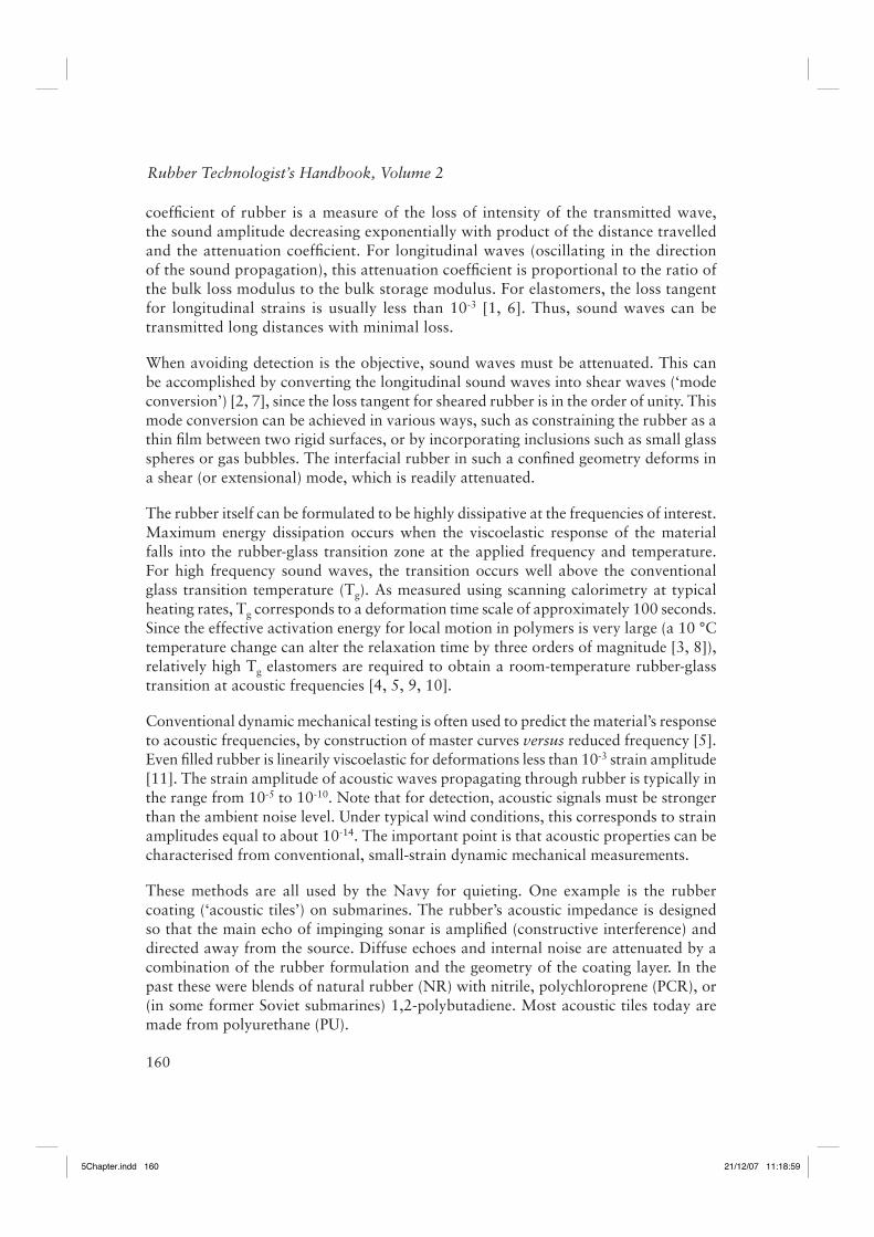
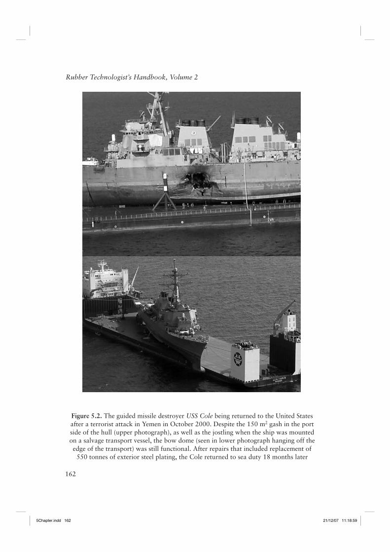
Although sound enables their detection, it also provides underwater ‘vision’ to sea vessels. The sonic transducers on Navy surface ships are covered with rubber (Figure 5.1), and contained in a steel-reinforced rubber dome. On large ships the dome is located on the bow (forward part of the lower hull) while on smaller vessels it is on the keel (keel refers to the bottom beam running from bow to stern). The purpose of the bow and keel domes is to provide a hydrodynamically smooth surface, to minimise noise from water fl ow, and to protect the transducer. The latter was exemplifi ed in the terrorist bombing of the USS Cole in October 2000. The dome and its transducer survived intact, despite the damage to the ship itself (Figure 5.2). The sonar dome must transmit with minimal loss the sound energy, and cannot be disrupted by the fl ow of seawater. Initially domes were made of steel but these had poor sound transmission, were susceptible to corrosion and marine fouling (from barnacles, sea weed, slime-producing bacteria, etc.), and required internal supports, which obstructed the sound. The fi rst rubber sonar dome was installed in 1965, with actual production beginning in 1972.
Figure 5.1. Sonar rubber bow dome
5Chapter.indd 1615Chapter.indd 161 21/12/07 11:18:5921/12/07 11:18:59
162
Rubber Technologist’s Handbook, Volume 2
Figure 5.2. The guided missile destroyer USS Cole being returned to the United States after a terrorist attack in Yemen in October 2000. Despite the 150 m2 gash in the port side of the hull (upper photograph), as well as the jostling when the ship was mounted on a salvage transport vessel, the bow dome (seen in lower photograph hanging off the edge of the transport) was still functional. After repairs that included replacement of 550 tonnes of exterior steel plating, the Cole returned to sea duty 18 months later
5Chapter.indd 1625Chapter.indd 162 21/12/07 11:18:5921/12/07 11:18:59
163
Naval and Space Applications of Rubber
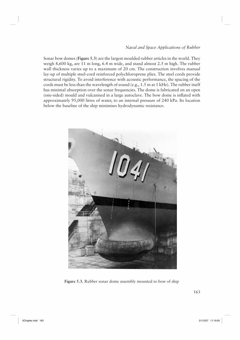
Sonar bow domes (Figure 5.3) are the largest moulded rubber articles in the world. They weigh 8,600 kg, are 11 m long, 6.4 m wide, and stand almost 2.5 m high. The rubber wall thickness varies up to a maximum of 20 cm. The construction involves manual lay-up of multiple steel-cord reinforced polychloroprene plies. The steel cords provide structural rigidity. To avoid interference with acoustic performance, the spacing of the cords must be less than the wavelength of sound (e.g., 1.5 m at 1 kHz). The rubber itself has minimal absorption over the sonar frequencies. The dome is fabricated on an open (one-sided) mould and vulcanised in a large autoclave. The bow dome is infl ated with approximately 95,000 litres of water, to an internal pressure of 240 kPa. Its location below the baseline of the ship minimises hydrodynamic resistance.
Figure 5.3. Rubber sonar dome assembly mounted to bow of ship
5Chapter.indd 1635Chapter.indd 163 21/12/07 11:19:0021/12/07 11:19:00
164
Rubber Technologist’s Handbook, Volume 2
Since their introduction, various improvements to the design of rubber sonar domes have been made, greatly increasing the expected lifetime. Problems with water migration and consequent wire corrosion were corrected by blocking the migration pathways in the wire. Problems with wire fatigue have been addressed by identifying cracks using X-ray radiography of the high stress regions. Such inspections have enabled targeted dome replacement, eliminating at-sea failures. Some sonar domes have been in continuous service for over twenty years.
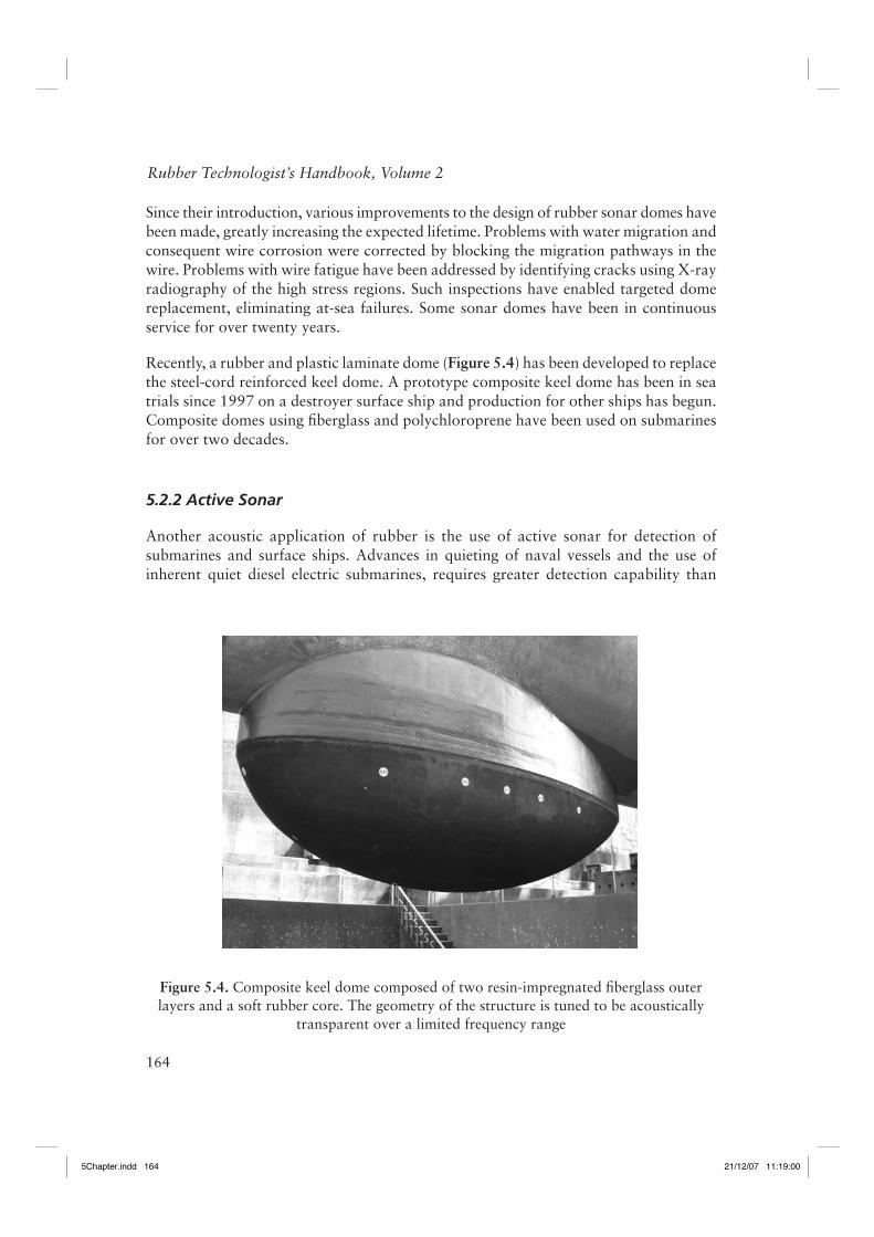
Recently, a rubber and plastic laminate dome (Figure 5.4) has been developed to replace the steel-cord reinforced keel dome. A prototype composite keel dome has been in sea trials since 1997 on a destroyer surface ship and production for other ships has begun. Composite domes using fi berglass and polychloroprene have been used on submarines for over two decades.
5.2.2 Active Sonar
Another acoustic application of rubber is the use of active sonar for detection of submarines and surface ships. Advances in quieting of naval vessels and the use of inherent quiet diesel electric submarines, requires greater detection capability than
Figure 5.4. Composite keel dome composed of two resin-impregnated fi berglass outer layers and a soft rubber core. The geometry of the structure is tuned to be acoustically
transparent over a limited frequency range
5Chapter.indd 1645Chapter.indd 164 21/12/07 11:19:0021/12/07 11:19:00
165
Naval and Space Applications of Rubber
passive sonar. Most active sonar relies on low frequencies (100-500 Hz) because the attenuation coeffi cient for sound waves is inversely proportional to the wavelength, and thus, active sonar can provide detection over many kilometers. The actual range of course depends on the size of the target, as well as sea state, temperature, and depth since these infl uence the dispersion and absorption of sound waves by the water. Of course, the longer wavelength reduces the resolution, resulting in poorer discrimination among undersea objects. Although a ship using active sonar reveals its location, the improved detection capabilities, especially in shallow water, makes it an invaluable anti-submarine warfare development [12]. More recently, high frequency sonar (>10 kHz) has been developed, which yields greater bearing resolution than conventional medium frequency systems. This provides better discrimination among undersea targets, bottom and surface echoes, and marine life, which can be crucial in shallow water operation. The higher absorption of high frequencies also facilitates undetected operation.
On surface ships, active sonar transducers are typically operated ‘off-board’, towed behind the vessel, while submarines employ both active and passive arrays mounted to the bow, keel and fi ns. Since a high sound level yields louder return echoes, long-range active sonar uses high sound levels. The volume can exceed 200 decibels at the source (right up to the point of cavitation), raising concerns about the possibility of hearing loss in marine animals [13-15]. Elastomers are used herein as an outer casing on the transducer, functioning analogously to the sonar domes on ships. The amount of acoustic information obtained using active sonar is enormous. Detection and classifi cation of submarines in the complex acoustic environment of shallow water requires sophisticated mathematical algorithms for processing the data. The acoustic properties of the rubber must be known to a high degree of accuracy so that the effect of the rubber on the transmitted sound can be corrected for. For low frequencies, for which the wavelengths are on the order of the test chamber, characterisation of acoustic properties of rubber can be complex [16].
5.2.3 Insulation
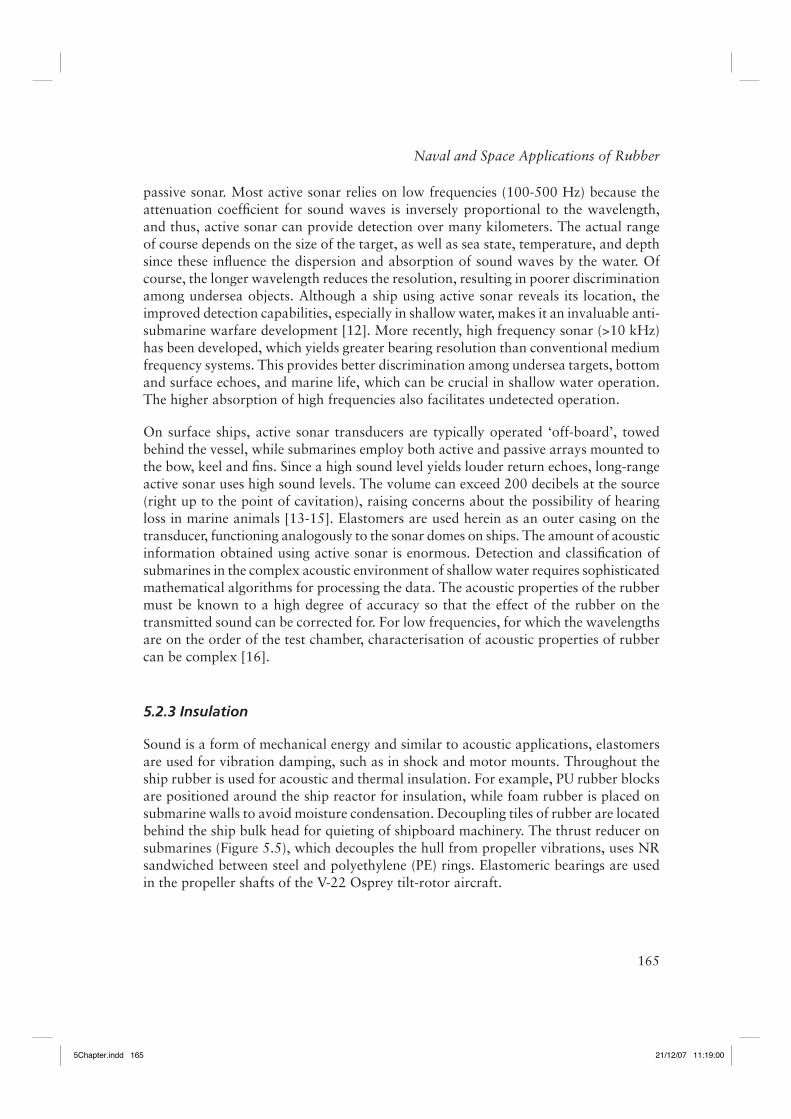
Sound is a form of mechanical energy and similar to acoustic applications, elastomers are used for vibration damping, such as in shock and motor mounts. Throughout the ship rubber is used for acoustic and thermal insulation. For example, PU rubber blocks are positioned around the ship reactor for insulation, while foam rubber is placed on submarine walls to avoid moisture condensation. Decoupling tiles of rubber are located behind the ship bulk head for quieting of shipboard machinery. The thrust reducer on submarines (Figure 5.5), which decouples the hull from propeller vibrations, uses NR sandwiched between steel and polyethylene (PE) rings. Elastomeric bearings are used in the propeller shafts of the V-22 Osprey tilt-rotor aircraft.
5Chapter.indd 1655Chapter.indd 165 21/12/07 11:19:0021/12/07 11:19:00
166
Rubber Technologist’s Handbook, Volume 2
5.3 Solid Rocket Propellants
Rocket propellants fall into two groups, liquid propellants, in which the fuel and oxidiser are stored separately, then mixed to effect combustion, and solid propellants, which rely on premixed ingredients residing in a casing, which also serves as the combustion chamber when the propellant is ignited. Although liquid propellants offer several important advantages (they yield substantially greater thrust and their combustion can be throttled or even halted and restarted), the storage requirements and handling complexity largely rule out their use for military fi repower. The fi rst rockets (dating to the fi rst millennium AD) used solid propellants - a Chinese variation on black powder (potassium nitrate, charcoal and sulfur). The rockets used in the War of 1812 (and referred to in the US national anthem) were of very similar design. The age of modern solid propellants began in the 1950s with the use of synthetic polymers as a binder and subsidiary fuel. This enabled moulding of the propellant. The other signifi cant development at the time was the use of aluminum power as fuel, which greatly increased the thrust obtainable.
The fi rst solid propellant ballistic missile, which used an elastomeric binder, was the US Navy Polaris, operational in 1960. It was launched from a submarine and carried a nuclear warhead. Presently both the US and the UK deploy the Trident intercontinental ballistic missile (ICBM). Trident missiles have three-stages, each using solid propellant fuel.
Figure 5.5. Thrust reducer used to decouple the submarine propeller shaft. The natural rubber is sandwiched between the steel ring and an outer layer of polyethylene
5Chapter.indd 1665Chapter.indd 166 21/12/07 11:19:0021/12/07 11:19:00
167
Naval and Space Applications of Rubber
The Air Force’s Minuteman is a solid propellant ICBM based in underground silos. Not having the complex storage and fi lling requirements of liquid propellant missiles, the Minuteman could be encased in thick concrete for protection from nuclear attack. Some Minuteman ICBM remain in service today, along with the MX (or Peacekeeper) missile. The Peacekeeper uses three stages of solid propellant, along with a post-boost liquid fuel motor.
Many spacecraft launches involve both propellant types – solid propellant boosters attached to liquid-propelled rockets. The Scout rocket (Figure 5.6), in use from 1960 through to 1994 to launch commercial and military satellites, was the only launch vehicle fuelled entirely by solid propellant. Its replacement is the Pegasus, an air-launched solid-propellant rocket. The Delta series of rockets derived from the Thor ballistic missile began in 1960 and continue presently as a civilian and government launcher. The Delta
Figure 5.6. Launch of Scout, the only United States’ launch vehicle fueled exclusively with solid propellants
5Chapter.indd 1675Chapter.indd 167 21/12/07 11:19:0021/12/07 11:19:00
168
Rubber Technologist’s Handbook, Volume 2
II and III versions (Figure 5.7) can have up to nine solid rocket motors strapped onto the fi rst stage, whose main engine is liquid fuelled as is the second stage. Two-stage Delta II rockets can launch payloads into low Earth orbit, while an optional third-stage, powered by solid propellant, is used for geosynchronous transfer orbit or deep space exploration. The newer Delta IV, which uses a liquid hydrogen/liquid oxygen fuel similar to the space shuttle, can launch substantially heavier payloads.
A generic recipe for military propellants is given in Table 5.1. The binder is a rubbery polymer, such as polysulfi de, polyvinyl chloride (PVC), PU, plasticised cellulose, polyisobutylene, polyvinylacetate, and carboxyl- or hydroxyl-terminated polybutadiene. While also serving as fuel, the function of the binder is to cohere the propellant into a thixotropic, low-viscosity paste that can be moulded into the desired shape. This
Figure 5.7. Delta III rocket with nine solid rocket motors strapped around the fi rst stage
5Chapter.indd 1685Chapter.indd 168 21/12/07 11:19:0021/12/07 11:19:00
169
Naval and Space Applications of Rubber
is followed by curing, which, for hydroxyl-terminated polybutadienes, is usually accomplished with isocyanates. The mechanical integrity of the cured propellant is important to its proper functioning. The propellant structure must withstand the pressure gradients developing within a few milliseconds of ignition. The triaxial tension exerted on the material cannot cause vacuole formation, which requires both adhesion of the polymer to the fi ller and good cohesive strength in the elastomer itself [17]. The shelf-life of a cured propellant must be many years, requiring resistance of the polymer to air oxidation and hydrolysis. The service life upon ignition is minutes or less, with the soot-free combustion of the polymer contributing to thrust generation.
5.4 Blast Mitigative Coatings
The rise of terrorism has led to efforts to develop methods of alleviating the effect of bomb explosions. A role for elastomers is their use as coatings to minimise the damage from the blast to the underlying structure and to personnel. Toward this end, the US military has been using polyurea spray-on elastomeric coatings on building and vehicles. The polyureas are formed from the reaction of isocyanates, based on diphenylmethane diisocyanate (MDI), with polyetheramines. The reaction is fast with gel times signifi cantly less than one minute. This means the reaction proceeds largely independently of ambient temperature and humidity, facilitating application of the coating under diverse conditions. The modulus of polyurea coatings can be tailored to span the range from moderately soft to very hard rubbers (e.g., from Shore A ~ 60 to Shore D ~ 75) [18]. They are very tough materials due to the plethora of intermolecular hydrogen bonds. Polyurea coatings have been used commercially since the early 1990s, their processing and property advantages leading to widespread use notwithstanding the higher cost.
Table 5.1. Representative solid rocket propellant formulationFunction Examples Typical mass (%)Oxidiser Ammonium perchlorate, ammonium nitrate,
nitronium perchlorate, potassium perchlorate, cyclotrimethylene trinitramine, cyclotetramethylene
tetranitramine
70
Fuel Aluminum, magnesium, beryllium, boron 14Binder Elastomer 11Plasticiser Dioctyl adipate, isodecyl pelargonete, dioctyl
phthalate, dioctyl azelate3
Catalyst Ferric oxide, butyl ferrocene, dibutyl ferrocene, lithium fl uoride
<1
Curing agent Isocyanate, epoxy 1Stabiliser Aluminum, zirconium, zirconium carbide <1
5Chapter.indd 1695Chapter.indd 169 21/12/07 11:19:0021/12/07 11:19:00
170
Rubber Technologist’s Handbook, Volume 2
Applications include concrete coatings and repair of roofs and parking decks, as well as liners for storage tanks, freight ships, and truck beds. Some of the more prominent uses include the Boston tunnel project, the Inchon, Korea airport, and the San Mateo, CA, bridge [19].
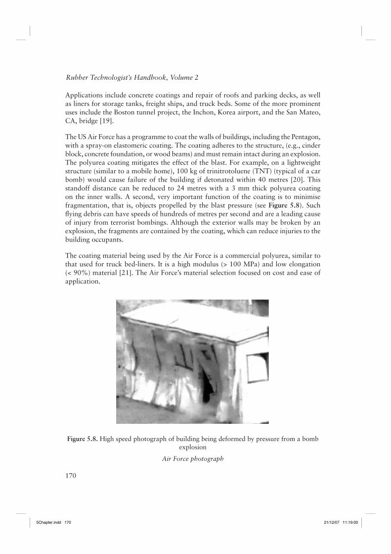
The US Air Force has a programme to coat the walls of buildings, including the Pentagon, with a spray-on elastomeric coating. The coating adheres to the structure, (e.g., cinder block, concrete foundation, or wood beams) and must remain intact during an explosion. The polyurea coating mitigates the effect of the blast. For example, on a lightweight structure (similar to a mobile home), 100 kg of trinitrotoluene (TNT) (typical of a car bomb) would cause failure of the building if detonated within 40 metres [20]. This standoff distance can be reduced to 24 metres with a 3 mm thick polyurea coating on the inner walls. A second, very important function of the coating is to minimise fragmentation, that is, objects propelled by the blast pressure (see Figure 5.8). Such fl ying debris can have speeds of hundreds of metres per second and are a leading cause of injury from terrorist bombings. Although the exterior walls may be broken by an explosion, the fragments are contained by the coating, which can reduce injuries to the building occupants.
The coating material being used by the Air Force is a commercial polyurea, similar to that used for truck bed-liners. It is a high modulus (> 100 MPa) and low elongation (< 90%) material [21]. The Air Force’s material selection focused on cost and ease of application.
Figure 5.8. High speed photograph of building being deformed by pressure from a bomb explosion
Air Force photograph
5Chapter.indd 1705Chapter.indd 170 21/12/07 11:19:0021/12/07 11:19:00
171
Naval and Space Applications of Rubber
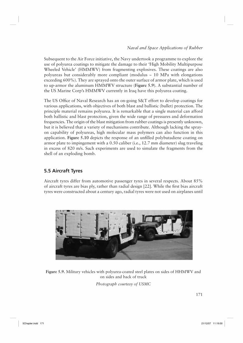
Subsequent to the Air Force initiative, the Navy undertook a programme to explore the use of polyurea coatings to mitigate the damage to their ‘High Mobility Multipurpose Wheeled Vehicle’ (HMMWV) from fragmenting explosives. These coatings are also polyureas but considerably more compliant (modulus ~ 10 MPa with elongations exceeding 600%). They are sprayed onto the outer surface of armor plate, which is used to up-armor the aluminum HMMWV structure (Figure 5.9). A substantial number of the US Marine Corp’s HMMWV currently in Iraq have this polyurea coating.
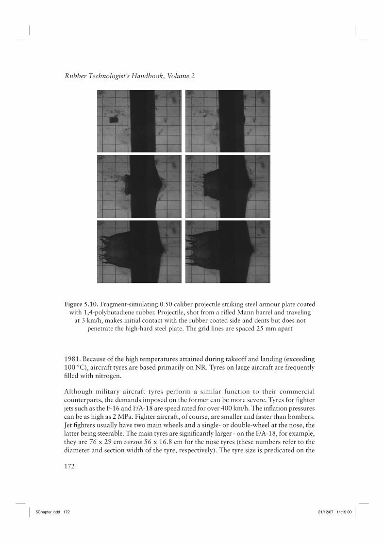
The US Offi ce of Naval Research has an on-going S&T effort to develop coatings for various applications, with objectives of both blast and ballistic (bullet) protection. The principle material remains polyurea. It is remarkable that a single material can afford both ballistic and blast protection, given the wide range of pressures and deformation frequencies. The origin of the blast mitigation from rubber coatings is presently unknown, but it is believed that a variety of mechanisms contribute. Although lacking the spray-on capability of polyureas, high molecular mass polymers can also function in this application. Figure 5.10 depicts the response of an unfi lled polybutadiene coating on armor plate to impingement with a 0.50 caliber (i.e., 12.7 mm diameter) slug traveling in excess of 820 m/s. Such experiments are used to simulate the fragments from the shell of an exploding bomb.
5.5 Aircraft Tyres
Aircraft tyres differ from automotive passenger tyres in several respects. About 85% of aircraft tyres are bias ply, rather than radial design [22]. While the fi rst bias aircraft tyres were constructed about a century ago, radial tyres were not used on airplanes until
Figure 5.9. Military vehicles with polyurea-coated steel plates on sides of HHMWV and on sides and back of truck
Photograph courtesy of USMC
5Chapter.indd 1715Chapter.indd 171 21/12/07 11:19:0021/12/07 11:19:00
172
Rubber Technologist’s Handbook, Volume 2
1981. Because of the high temperatures attained during takeoff and landing (exceeding 100 °C), aircraft tyres are based primarily on NR. Tyres on large aircraft are frequently fi lled with nitrogen.
Although military aircraft tyres perform a similar function to their commercial counterparts, the demands imposed on the former can be more severe. Tyres for fi ghter jets such as the F-16 and F/A-18 are speed rated for over 400 km/h. The infl ation pressures can be as high as 2 MPa. Fighter aircraft, of course, are smaller and faster than bombers. Jet fi ghters usually have two main wheels and a single- or double-wheel at the nose, the latter being steerable. The main tyres are signifi cantly larger - on the F/A-18, for example, they are 76 x 29 cm versus 56 x 16.8 cm for the nose tyres (these numbers refer to the diameter and section width of the tyre, respectively). The tyre size is predicated on the
Figure 5.10. Fragment-simulating 0.50 caliber projectile striking steel armour plate coated with 1,4-polybutadiene rubber. Projectile, shot from a rifl ed Mann barrel and traveling
at 3 km/h, makes initial contact with the rubber-coated side and dents but does not penetrate the high-hard steel plate. The grid lines are spaced 25 mm apart
5Chapter.indd 1725Chapter.indd 172 21/12/07 11:19:0021/12/07 11:19:00
173
Naval and Space Applications of Rubber
weight of the aircraft. When the gross weight of the F-16 was increased by almost a factor of two, a signifi cantly larger tyre size had to be adopted.
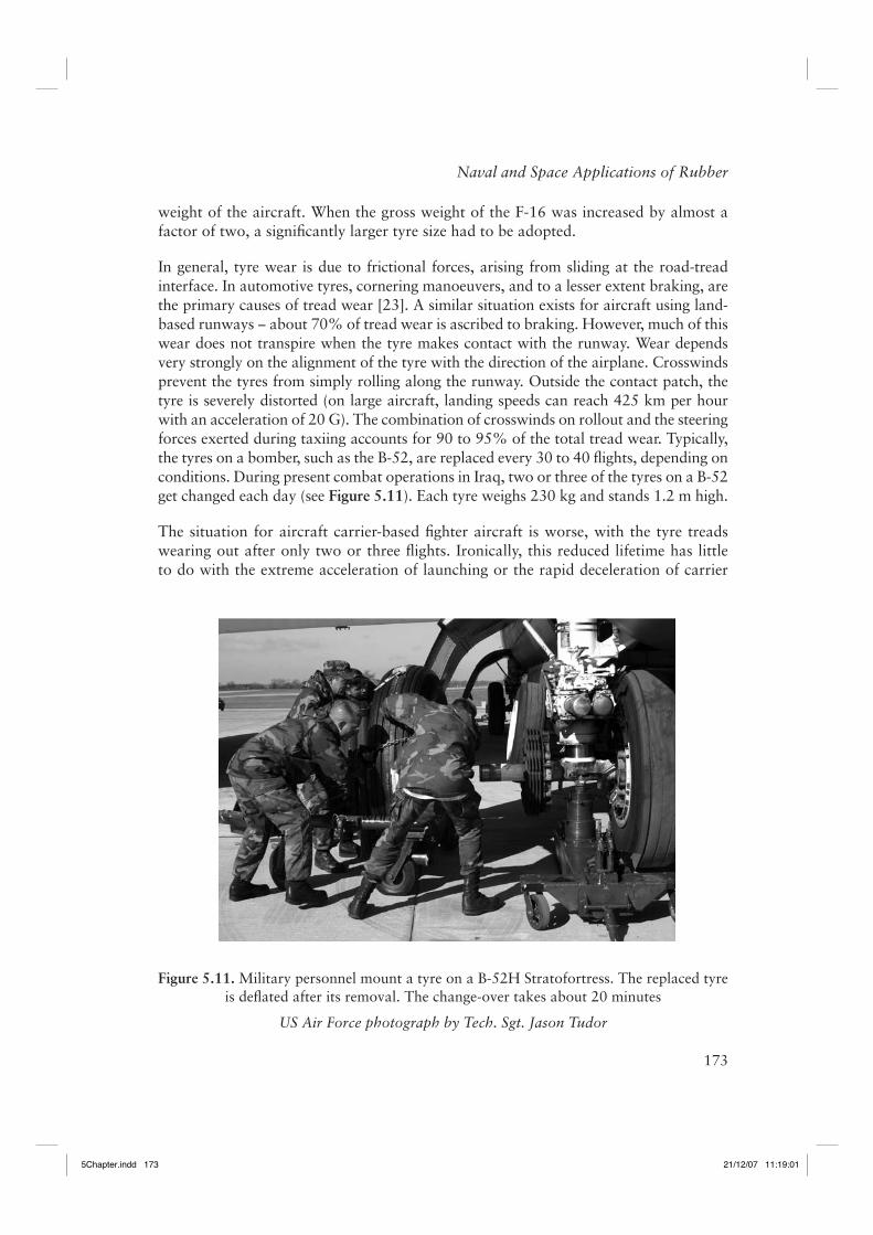
In general, tyre wear is due to frictional forces, arising from sliding at the road-tread interface. In automotive tyres, cornering manoeuvers, and to a lesser extent braking, are the primary causes of tread wear [23]. A similar situation exists for aircraft using land-based runways − about 70% of tread wear is ascribed to braking. However, much of this wear does not transpire when the tyre makes contact with the runway. Wear depends very strongly on the alignment of the tyre with the direction of the airplane. Crosswinds prevent the tyres from simply rolling along the runway. Outside the contact patch, the tyre is severely distorted (on large aircraft, landing speeds can reach 425 km per hour with an acceleration of 20 G). The combination of crosswinds on rollout and the steering forces exerted during taxiing accounts for 90 to 95% of the total tread wear. Typically, the tyres on a bomber, such as the B-52, are replaced every 30 to 40 fl ights, depending on conditions. During present combat operations in Iraq, two or three of the tyres on a B-52 get changed each day (see Figure 5.11). Each tyre weighs 230 kg and stands 1.2 m high.
The situation for aircraft carrier-based fi ghter aircraft is worse, with the tyre treads wearing out after only two or three fl ights. Ironically, this reduced lifetime has little to do with the extreme acceleration of launching or the rapid deceleration of carrier
Figure 5.11. Military personnel mount a tyre on a B-52H Stratofortress. The replaced tyre is defl ated after its removal. The change-over takes about 20 minutes
US Air Force photograph by Tech. Sgt. Jason Tudor
5Chapter.indd 1735Chapter.indd 173 21/12/07 11:19:0121/12/07 11:19:01
174
Rubber Technologist’s Handbook, Volume 2
landings, for example, during launch, an F/A-18 Hornet attains a speed of 265 km/h within a space of 75 m. The acceleration relies on steam-assisted catapulting, while landings utilise arresting wires rather than relying on tyre friction. Thus, the contribution to tread wear is minimal for both cases. An additional factor is that carrier launches and landings take place with the ship turned into the wind, which adds (or subtracts) to the relative speed, putting less demand on the tyres.
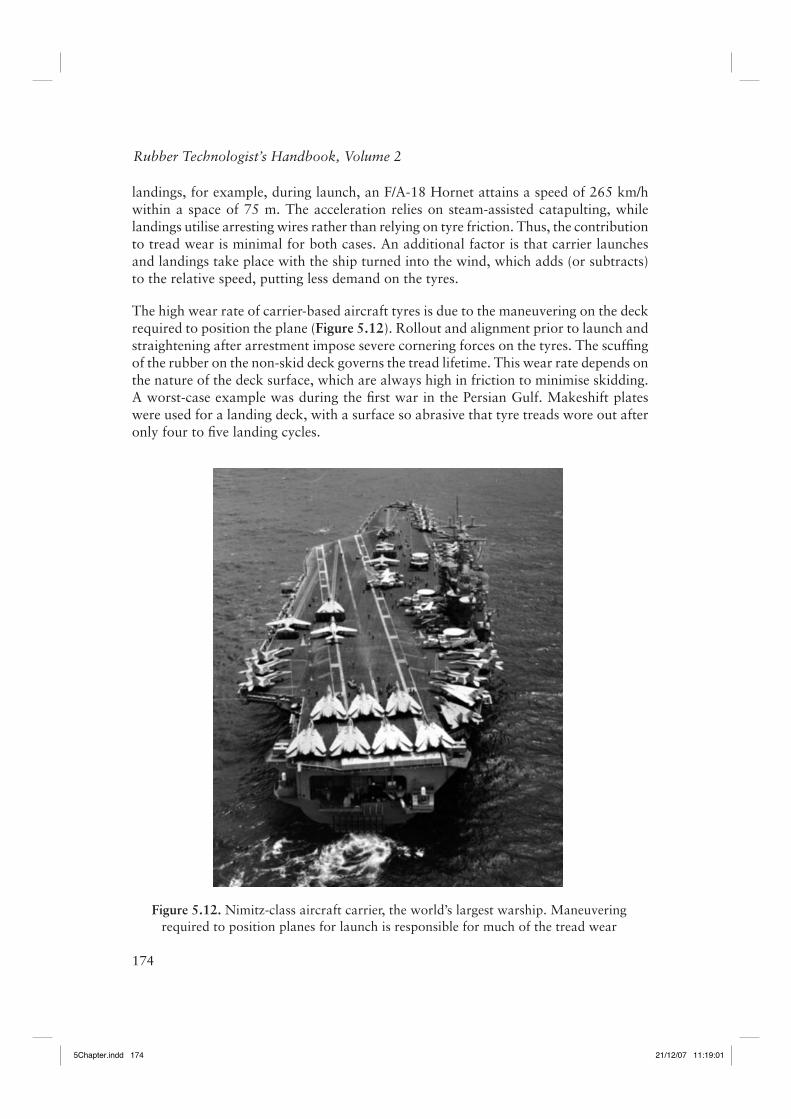
The high wear rate of carrier-based aircraft tyres is due to the maneuvering on the deck required to position the plane (Figure 5.12). Rollout and alignment prior to launch and straightening after arrestment impose severe cornering forces on the tyres. The scuffi ng of the rubber on the non-skid deck governs the tread lifetime. This wear rate depends on the nature of the deck surface, which are always high in friction to minimise skidding. A worst-case example was during the fi rst war in the Persian Gulf. Makeshift plates were used for a landing deck, with a surface so abrasive that tyre treads wore out after only four to fi ve landing cycles.
Figure 5.12. Nimitz-class aircraft carrier, the world’s largest warship. Maneuvering required to position planes for launch is responsible for much of the tread wear
5Chapter.indd 1745Chapter.indd 174 21/12/07 11:19:0121/12/07 11:19:01
175
Naval and Space Applications of Rubber
In aircraft used at high speed for extended durations, aerodynamic friction on the skin creates heat, which radiates to the tyres. The tyres themselves can be given a silver coating to refl ect the heat. The heating problem manifests itself with blow-out of the tyres upon landing.
The tyres for the space shuttle are not especially large, 81 x 22 cm for the nose and 113 x 41 cm (diameter x width) for the main tyres, even though the shuttle weighs as much as 110,000 kg on landing. This means the main landing tyres support about three times the load of a tyre on a Boeing 747. The space shuttle tyres are infl ated with over 2 MPa of nitrogen. The main tyres on the shuttle are used only once, while the nose tyres are used for two landings.
5.6 Airships
There are two types of airships: Blimps are non-rigid airships lacking any internal support structure. They rely on the pressure of the internal gas, enclosed in a rubber-coated fabric, for support and to provide lift. The gas is commonly helium at pressures exceeding ambient. Hydrogen, which provides about 10% more buoyancy (lifting capacity ~1.1 kg/m3 versus 1.02 kg/m3 for He), still fi nds limited use, notwithstanding its fl ammability (it has an energy content threefold higher than gasoline). Rigid airships (e.g., ‘Zeppelins’) have rigid internal frames and are largely obsolete. The main component of an airship is the envelope, which contains the pressurising gas. On the Goodyear blimps, which were used by the military during World War II, this envelope is a PCR-impregnated polyester fabric. Because of the large gas volume (about 7 million litres) and low pressure, gas leaks are very slow. For this reason the elastomer selection is guided by manufacturing ease and mechanical durability, as well as by the requirement of low permeability. In 1994 tests by the British Ministry of Defence determined after hundreds of bullet punctures of an airship envelope, the craft remained infl ated and aloft for several hours.
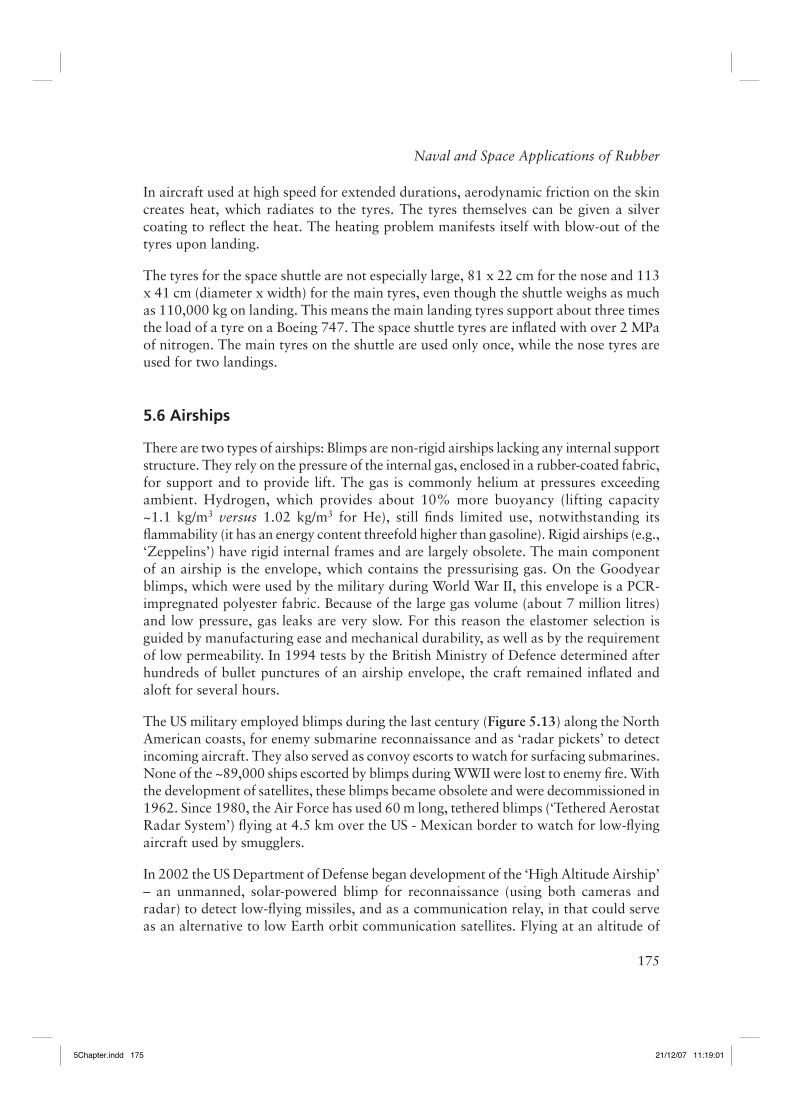
The US military employed blimps during the last century (Figure 5.13) along the North American coasts, for enemy submarine reconnaissance and as ‘radar pickets’ to detect incoming aircraft. They also served as convoy escorts to watch for surfacing submarines. None of the ~89,000 ships escorted by blimps during WWII were lost to enemy fi re. With the development of satellites, these blimps became obsolete and were decommissioned in 1962. Since 1980, the Air Force has used 60 m long, tethered blimps (‘Tethered Aerostat Radar System’) fl ying at 4.5 km over the US - Mexican border to watch for low-fl ying aircraft used by smugglers.
In 2002 the US Department of Defense began development of the ‘High Altitude Airship’ – an unmanned, solar-powered blimp for reconnaissance (using both cameras and radar) to detect low-fl ying missiles, and as a communication relay, in that could serve as an alternative to low Earth orbit communication satellites. Flying at an altitude of
5Chapter.indd 1755Chapter.indd 175 21/12/07 11:19:0121/12/07 11:19:01
176
Rubber Technologist’s Handbook, Volume 2
20 km, the blimp would be beyond the range of ground-launched antiaircraft weapons. Prototypes will be 150 m long with a volume of 150 million litres (25 times larger than the Goodyear blimp), and carry a 1800 kg payload. One technical barrier is achieving suffi cient buoyancy in the stratosphere - this may require new technologies for the envelope. Since the internal gas will expand as the blimp rises, it will initially be fi lled with air, which is replaced by pressurised helium gas as higher altitudes are reached. Initially fl ight tests are contemplated in 2008.
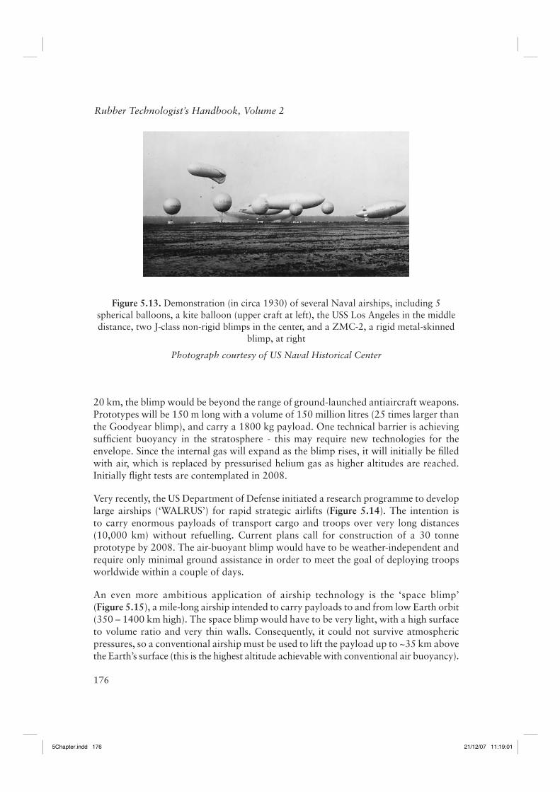
Very recently, the US Department of Defense initiated a research programme to develop large airships (‘WALRUS’) for rapid strategic airlifts (Figure 5.14). The intention is to carry enormous payloads of transport cargo and troops over very long distances (10,000 km) without refuelling. Current plans call for construction of a 30 tonne prototype by 2008. The air-buoyant blimp would have to be weather-independent and require only minimal ground assistance in order to meet the goal of deploying troops worldwide within a couple of days.
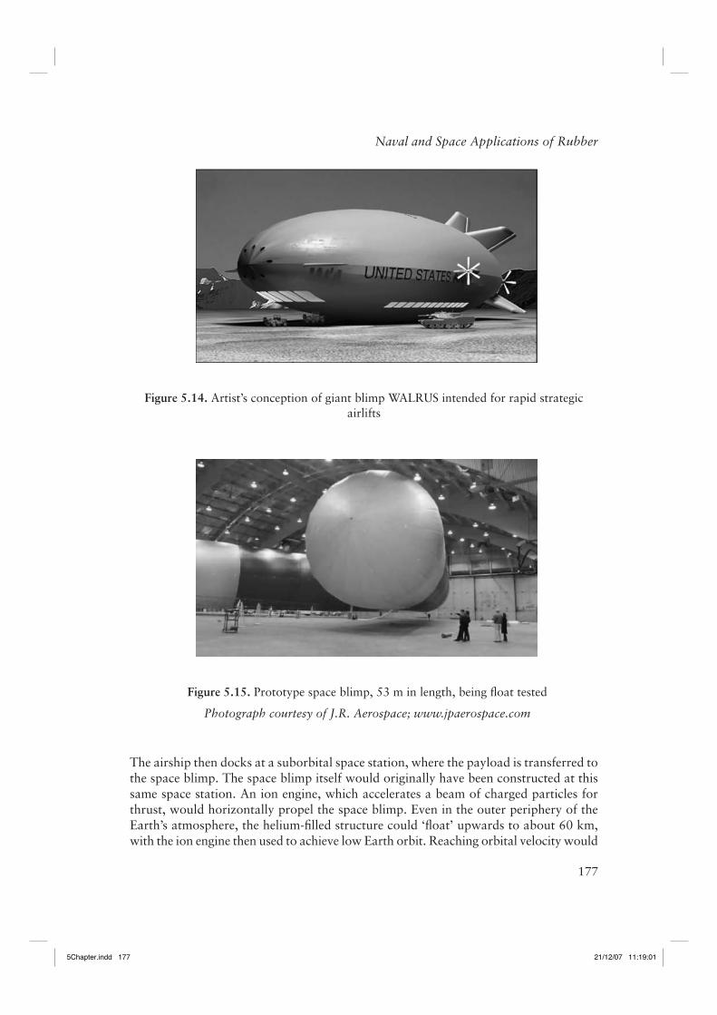
An even more ambitious application of airship technology is the ‘space blimp’ (Figure 5.15), a mile-long airship intended to carry payloads to and from low Earth orbit (350 – 1400 km high). The space blimp would have to be very light, with a high surface to volume ratio and very thin walls. Consequently, it could not survive atmospheric pressures, so a conventional airship must be used to lift the payload up to ~35 km above the Earth’s surface (this is the highest altitude achievable with conventional air buoyancy).
Figure 5.13. Demonstration (in circa 1930) of several Naval airships, including 5 spherical balloons, a kite balloon (upper craft at left), the USS Los Angeles in the middle distance, two J-class non-rigid blimps in the center, and a ZMC-2, a rigid metal-skinned
blimp, at right
Photograph courtesy of US Naval Historical Center
5Chapter.indd 1765Chapter.indd 176 21/12/07 11:19:0121/12/07 11:19:01
177
Naval and Space Applications of Rubber
The airship then docks at a suborbital space station, where the payload is transferred to the space blimp. The space blimp itself would originally have been constructed at this same space station. An ion engine, which accelerates a beam of charged particles for thrust, would horizontally propel the space blimp. Even in the outer periphery of the Earth’s atmosphere, the helium-fi lled structure could ‘fl oat’ upwards to about 60 km, with the ion engine then used to achieve low Earth orbit. Reaching orbital velocity would
Figure 5.14. Artist’s conception of giant blimp WALRUS intended for rapid strategic airlifts
Figure 5.15. Prototype space blimp, 53 m in length, being fl oat tested
Photograph courtesy of J.R. Aerospace; www.jpaerospace.com
5Chapter.indd 1775Chapter.indd 177 21/12/07 11:19:0121/12/07 11:19:01
178
Rubber Technologist’s Handbook, Volume 2
require several days. The putative advantage of the space blimp is economic, i.e., a low cost per payload weight. It could be confi gured for both cargo and passengers and use a three-member crew.
5.7 Infl atable Seacraft
5.7.1 Combat Rubber Raiding Craft
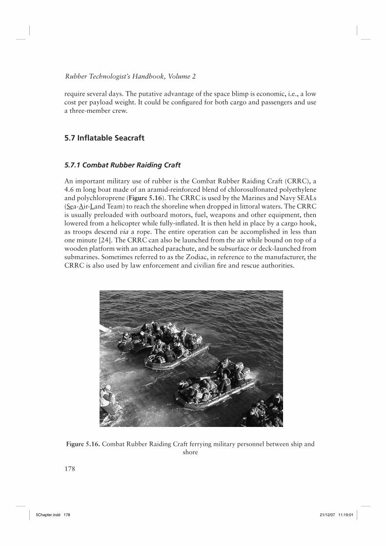
An important military use of rubber is the Combat Rubber Raiding Craft (CRRC), a 4.6 m long boat made of an aramid-reinforced blend of chlorosulfonated polyethylene and polychloroprene (Figure 5.16). The CRRC is used by the Marines and Navy SEALs (Sea-Air-Land Team) to reach the shoreline when dropped in littoral waters. The CRRC is usually preloaded with outboard motors, fuel, weapons and other equipment, then lowered from a helicopter while fully-infl ated. It is then held in place by a cargo hook, as troops descend via a rope. The entire operation can be accomplished in less than one minute [24]. The CRRC can also be launched from the air while bound on top of a wooden platform with an attached parachute, and be subsurface or deck-launched from submarines. Sometimes referred to as the Zodiac, in reference to the manufacturer, the CRRC is also used by law enforcement and civilian fi re and rescue authorities.
Figure 5.16. Combat Rubber Raiding Craft ferrying military personnel between ship and shore
5Chapter.indd 1785Chapter.indd 178 21/12/07 11:19:0121/12/07 11:19:01
179
Naval and Space Applications of Rubber
5.7.2 Hovercraft
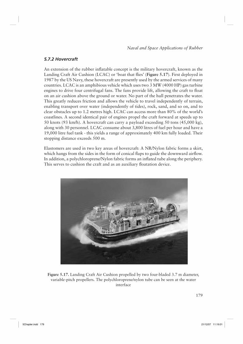
An extension of the rubber infl atable concept is the military hovercraft, known as the Landing Craft Air Cushion (LCAC) or ‘boat that fl ies’ (Figure 5.17). First deployed in 1987 by the US Navy, these hovercraft are presently used by the armed services of many countries. LCAC is an amphibious vehicle which uses two 3 MW (4000 HP) gas turbine engines to drive four centrifugal fans. The fans provide lift, allowing the craft to fl oat on an air cushion above the ground or water. No part of the hull penetrates the water. This greatly reduces friction and allows the vehicle to travel independently of terrain, enabling transport over water (independently of tides), rock, sand, and so on, and to clear obstacles up to 1.2 metres high. LCAC can access more than 80% of the world’s coastlines. A second identical pair of engines propel the craft forward at speeds up to 50 knots (93 km/h). A hovercraft can carry a payload exceeding 50 tons (45,000 kg), along with 30 personnel. LCAC consume about 3,800 litres of fuel per hour and have a 19,000 litre fuel tank - this yields a range of approximately 400 km fully loaded. Their stopping distance exceeds 500 m.
Elastomers are used in two key areas of hovercraft: A NR/Nylon fabric forms a skirt, which hangs from the sides in the form of conical fl aps to guide the downward airfl ow. In addition, a polychloroprene/Nylon fabric forms an infl ated tube along the periphery. This serves to cushion the craft and as an auxiliary fl oatation device.
Figure 5.17. Landing Craft Air Cushion propelled by two four-bladed 3.7 m diameter, variable-pitch propellers. The polychloroprene/nylon tube can be seen at the water
interface
5Chapter.indd 1795Chapter.indd 179 21/12/07 11:19:0121/12/07 11:19:01
180
Rubber Technologist’s Handbook, Volume 2
The primary military use of hovercraft is for ship to sea transport, shuttling troops and equipment, and for traversing beaches. They are especially effective for mine sweeping in shallow waters and have also been used for humanitarian relief. LCAC played an important role in the recent ‘Iraqi Freedom’ military campaign.
Presently the US Navy is collaborating in the development of an advanced hovercraft of Russian design, the EKIP (Russian acronym for Ecology and Progress). This vehicle will support a 100 ton payload, at speeds up to 700 km/h in air and 160 km/h while skimming the surface. One intended non-military application is fi ghting forest fi res.
5.8 Rubber Sealants
The ability of an elastomer to store energy makes it an ideal material for sealing purposes. The stored energy causes retraction of the rubber after completion of the duty cycle. O-rings, gaskets, and other sealants are widely used in the military and aerospace industries. Most of these products are supplied by private companies who insist on the confi dentiality of the formulations, and thus, generally, only the base polymer can be identifi ed with the other ingredients being proprietary.
Polysulfi de rubber is a common gasket material and caulk on military aircraft (for fl oorboards, windscreens, canopies, and so on) and rockets (e.g., at nozzle to case joints), and as grout on aircraft carrier runways. These seals require periodic replacement. However, many of the polysulfi de materials release volatile organic compounds during cure. They also contain chromium, so that their disposal is treated as hazardous waste. For these reasons polysulfi des are being replaced with more benign materials, for example with polytetrafl ouroethylene foam or adhesive tape.
More advanced sealants are based on polyphosphazene fl uoroelastomers [25]. Originally developed by the Firestone Tyre & Rubber Co. for the US Army, polyphosphazene elastomers have a phosphorous-nitrogen repeat unit, [NP(OR)(OR´)], with various organic constituents yielding different properties. In polyphosphazene fl uoroelastomers, the pendant moiety is OCH2CF3 or other fl uoroalkoxy groups. These materials have a wide service range (minus 65 to 175 °C), being used in both aerospace and military applications. The good fuel and oil resistance of polyphosphazene fl uoroelastomer has led to their use for O-rings and diaphragms in jet engines. They are also used in vibration isolation due to their large, broadband damping properties.
When the constituent is an aryloxy group, rather than a fluoroalkoxy, the resulting elastomer is flame-resistant and produces low smoke upon burning. Polyaryloxyphophazenes have been used for wire and cable insulation and insulating foams, although cost is a barrier to more widespread usage [25]. Work has been done to develop blends of polyaryloxyphophazenes with PU as fl ame-retardant materials for use on aircraft. The most infamous use of rubber in aerospace applications was the O-ring
5Chapter.indd 1805Chapter.indd 180 21/12/07 11:19:0121/12/07 11:19:01
181
Naval and Space Applications of Rubber
in the Challenger Space Shuttle [26]. n 1986 during its tenth mission, the Challenger exploded 73 seconds after launch due to a leak in the right solid rocket booster (SRB), which ignited the hydrogen tank. The leak was caused by failure of an O-ring to seal the gap between the two lower steel sections of the SRB. The joint between the sections contained two 11 m O-rings (two for redundancy), each 7 mm in diameter. The O-ring material was a (proprietary) 90-durometer fl uoroelastomer, coated with a zinc chromate putty to protect the rubber from the hot exhaust gases. It was known that the sealing capabilities of the O-ring were compromised by low temperatures. There was no data for performance below 12 °C and at this temperature the predicted failure rate of the seals was 33% [27]. Nevertheless, 12 °C was recommended as the lower temperature limit for launching. At the time of the shuttle’s launch, the ambient temperature was 22 °C, with that at the SRB joint estimated to be -2 ± 3 °C. At this low temperature, the rubber lacked the resilience necessary to follow the opening in the gap between the tang and cleavis joint. Hot gases escaped and ultimately led to the explosion of the shuttle. For subsequent missions, the same fl uoroelastomer was used, but in conjunction with heaters to provide temperature control.
5.9 Miscellaneous Applications
5.9.1 Rubber Bullets
An offbeat military application of rubber is the use of rubber bullets as non-lethal weapons. Peace-keeping missions involving crowd control, as well as military prison duty, often require the use of non-deadly force. After the September 11, 2001 terrorist attacks, the US military stock-piled large quantities of rubber bullets. In military parlance, the function of these and other non-lethal weaponry is ‘to incapacitate personnel and material, while minimising fatalities, permanent injuries to personnel, and undesired damage to property and the environment’ [28]. Civilian police and security services employ rubber-coated metal bullets, plastic (e.g., PVC or polymethyl methacrylate) bullets, and beanbags fi lled with lead pellets for riot control and personnel protection. However, rubber bullets generally cause less injury than other nonlethal rounds. The misuse of nonlethal weaponry is a paramount legal issue [29]. Rifl es, grenades and a variant on the claymore mine are used by the military to spray nonlethal rubber pellets. The polymers used in various rubber bullets include ethylene-propylene-diene (EPDM), polybutadiene, natural and synthetic polyisoprene, styrene-butadiene copolymer, butyl rubber, and various blends thereof [30-32]. The elastomer is usually highly fi lled with carbon black, clay, calcium carbonate, or metallic fi llers such as copper or iron.
5Chapter.indd 1815Chapter.indd 181 21/12/07 11:19:0121/12/07 11:19:01
182
Rubber Technologist’s Handbook, Volume 2
5.9.2 Intrusion Barriers
Marine security zones are demarcated by barriers to prevent unauthorised entry. One method used by the US Navy against intrusion by small craft is to string a cable across the entryway. Typically the cable is steel encased in rubber connecting cables. The line is anchored to both the sea fl oor and the shore, with buoyancy maintained by foam-fi lled structures attached across its length. The latter can be brightly coloured to enhance visibility. A 90 m EPDM/steel cable assembly has been operation at a Naval base in Norfolk, VA, since 2002.
5.9.3 Elastomeric Torpedo Launcher
Rubber can function very effectively as an energy storage device (mechanical capacitor) due to its ability to store and quickly return a large energy density. This feature of rubber is exploited in commercial applications, for example the propulsion mechanism of aerosol containers [33, 34] and for intravenous drug delivery. Other ideas, such as regenerative braking systems for automobiles [35] and pressurised systems for carbonated beverage containers, were technically sound but failed due to other factors. In a propulsion device the stored energy is converted to the kinetic energy of a projectile, with the performance dependent on the amount of stored energy. Although this is proportional to the modulus of the material, even soft elastomers can yield large energy densities due to their high elongation. Moreover, this energy can be recovered very rapidly.
Although an internal propulsion mechanism takes over after launching, the torpedo must be ejected from the submarine. This requires that an exit velocity of 50 km/h be reached in one second – this is about 3 G acceleration (The Mark 48 torpedo, for example, weighs 1600 kg). Conventional torpedo launchers employ ram pumps or 1.5 MW (2000 HP) air turbine pumps, which rely on pressurised air for ejection. These systems weigh over 20,000 kg, cost millions of dollars, and take up space inside the pressure hull. The advantages of an elastomeric ejection system include a reduction in weight, cost, and complexity, as well as superior acoustic properties. Another benefi t is that the elastomeric device can be situated in the seawater, between the pressure and outer hulls.
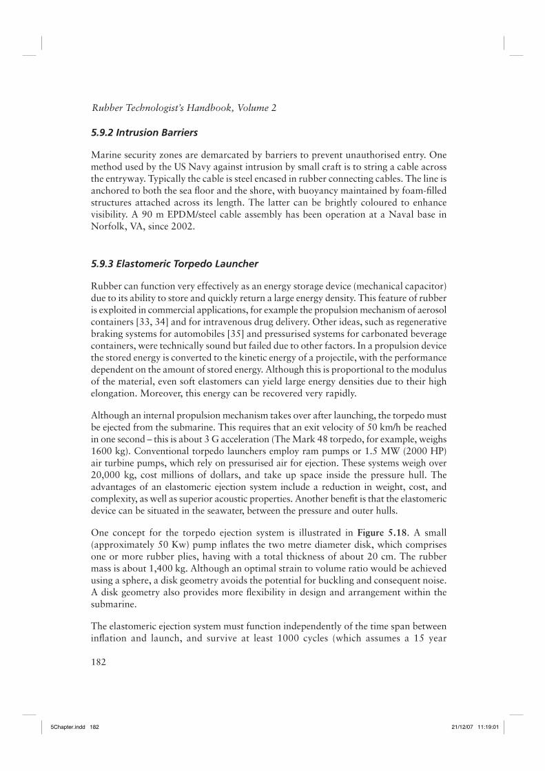
One concept for the torpedo ejection system is illustrated in Figure 5.18. A small (approximately 50 Kw) pump infl ates the two metre diameter disk, which comprises one or more rubber plies, having with a total thickness of about 20 cm. The rubber mass is about 1,400 kg. Although an optimal strain to volume ratio would be achieved using a sphere, a disk geometry avoids the potential for buckling and consequent noise. A disk geometry also provides more fl exibility in design and arrangement within the submarine.
The elastomeric ejection system must function independently of the time span between infl ation and launch, and survive at least 1000 cycles (which assumes a 15 year
5Chapter.indd 1825Chapter.indd 182 21/12/07 11:19:0121/12/07 11:19:01
183
Naval and Space Applications of Rubber
Figure 5.18. Schematic depiction of elastomeric ejection system. From top to bottom: Pump infl ates rubber disk, which retracts when the slide valve is opened, accelerating
torpedo from shutterway
5Chapter.indd 1835Chapter.indd 183 21/12/07 11:19:0121/12/07 11:19:01
184
Rubber Technologist’s Handbook, Volume 2
lifetime). The criteria governing the rubber include high elastic energy, minimal creep and hysteresis, and suffi cient fatigue life. Testing of full-scale prototypes indicated that the outer circumference of the disk was the locus of failure. This is due to the presence of planar extension mode of deformation at the periphery, while toward the center the rubber is in a state of biaxial extension [36].
The material for the elastomeric launcher is natural rubber, deproteinised to minimise water absorption [37, 38], with a semi-EV cure system [2, 39]. A small recharge pump infl ates the disk with water drawn from the ocean. A biaxial strain of about 100% is attained in the rubber, which yields 1.8 MW (2,400 HP). Opening of a slide valve collapses the rubber disk, forcing water into the torpedo tube to effect the launching. Currently the elastomeric ejection system is under consideration for installation in future submarines [40].
5.9.4 Mobile Offshore Base
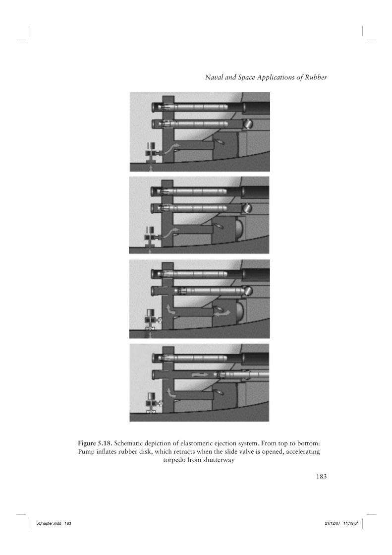
Another potential future naval use of rubber is in the Mobil Offshore Base (MOB). MOB, or ‘artifi cial beach’, would be the largest fl oating structure ever built − a self-powered, mile-long open-sea platform [41-43]. Intended to be deployed in international waters in proximity to areas of military interest, MOB would house 70 acres (0.3 km2) of the enclosed storage space, while simultaneously serving as a runway for fi xed-wing aircraft. The size and functions of the MOB platform make it unique compared to other fl oating structures (Figure 5.19).
The eventual design for the MOB has yet to be decided, with various concepts being investigated. The platform could be a single, continuous elastic hull, or involve as many as fi ve individual modules, connected by hinges or elastic connectors. A critical aspect of the design is the response of the runway structure to wave-induced dynamics over its one mile length. The base must support fi xed wing cargo planes operating up to sea state 6 (4.6 m waves and wind speeds of 56 km/h). The platform itself must survive all sea states, including hurricanes and typhoons (15 m waves and wind speeds exceeding 160 km/h).
The connectors between modules, and a method to control positioning, are the critical feasibility aspects of a modular approach. The assembly must be rigid enough to minimise relative motion between modules in order to provide a useable fl ight deck, but also be suffi ciently compliant to reduce stresses generated over its length by ocean waves. Various connections methods are under consideration. One promising approach employs fi ve metre long elastomeric conical connectors between the modules [44]. Elastomers offer the ability to tailor both the frequency response and the damping behavior of the connector. Advantage is taken of a conical geometry and the inherent damping afforded by rubber to control yaw motions, enhancing MOB maneuverability.
5Chapter.indd 1845Chapter.indd 184 21/12/07 11:19:0221/12/07 11:19:02
185
Naval and Space Applications of Rubber
The technical feasibility of the MOB concept has been established and currently the program is under assessment by the Defense Department and Congress. Potential off-shoots of the fl oating platform technology, such off-shore airports, are also being explored.
Acknowledgements
Helpful comments from Robert Corsaro and Peter Mott of NRL are gratefully appreciated. This work was supported by the Offi ce of Naval Research.
Figure 5.19. Illustration of one conception of the Mobile Offshore Base
With permission from McDermott Technology, Inc.
5Chapter.indd 1855Chapter.indd 185 21/12/07 11:19:0221/12/07 11:19:02
186
Rubber Technologist’s Handbook, Volume 2
References
1. A.N. Wecksler, Rubber Age, 1941, 4, 31.
2. I.S. Choi, C.M. Roland and L.C. Bissonnette, Rubber Chemistry & Technology 1994, 67, 5, 892.
3. D. Vergun, Sea Power, April 2003, 46, 4.
4. M.P. Hagelberg and R.D. Corsaro, Journal of the Acoustic Society of America, 1985, 77, 1222.
5. R. N. Capps, Elastomeric Materials for Acoustical Applications, Naval Research Laboratory, Washington, DC, USA, 1989.
6. J-D Ferry, Viscoelastic Properties of Polymers, 3rd Edition, Wiley, New York, NY, USA, 1980.
7. J. Jarzynski in Sound and Vibration Damping with Polymers, Eds., R.D. Corsaro and L.H. Sperling, ACS Symposium Series No.424, American Chemical Society, Washington, DC, USA, 1990.
8. C.M. Roland, K.L. Ngai, P.G. Santangelo, X.H. Qiu, M.D. Ediger and D.J. Plazek, Macromolecules, 2001, 34, 18, 6159.
9. R.E. Wetton, Applied Acoustics 1978, 11, 2, 77.
10. A.K. Sircar and M.I. Drake in Sound and Vibration Damping with Polymers, Eds., R.D. Corsaro and L.H. Sperling, ACS Symposium Series No.424, American Chemical Society, Washington, DC, USA, 1990.
11. M. Roland and G.F. Lee, Rubber Chemistry & Technology, 1990, 63, 4, 554.
12. G.D. Tyler, Johns Hopkins APL Technical Digest, 1992, 13, 145.
13. M.C. Hastings, A.N. Popper, J.J. Finneran and P.J. Lanford, Journal of the Acoustical Society of America, 1996, 99, 3, 1759.
14. L.A. Crum and Y. Mao, Journal of the Acoustical Society of America, 1996, 99, 5, 2898.
15. L.A. Crum, M.R. Bailey, J.F. Guan, P.R. Hilmo, S.G. Kargl, T.J. Matula and O.A. Sapozhnikov, Acoustic Research Letters Online, 2005, 6, 214.
16. P.H. Mott, C.M. Roland, and R.D. Corsaro, Journal of the Acoustical Society of America, 2002, 111, 4, 1782.
5Chapter.indd 1865Chapter.indd 186 21/12/07 11:19:0221/12/07 11:19:02
187
Naval and Space Applications of Rubber
17. Y. Traissac, J. Ninous, R. Neviere and J. Pouyet, Rubber Chemistry & Technology, 1995, 68, 1, 146.
18 M. Broekaert, Huntsman Corporation Technical Bulletin, 2002.
19. J.L. Reddinger and K.M. Hillman, Huntsman Corporation Technical Bulletin, 2001.
20. K.J. Knox, M.I. Hammons, T.T. Lewis, and J.R. Porter, Polymer Materials for Structural Retrofi t, Air Force Research Laboratory Technical Report, AFRL, Tyndall AFB, FL, USA, 2001.
21. J.S. Davidson, J.R. Porter, R.J. Dinan, M.I. Hammons and J.D. Connell, Journal of Performance of Constructed Facilities, 2004, 18, 2, 100.
22. P. Raleigh, Rubber and Plastics News, Sept. 2002, 9, 13.
23. A.G. Veith, Rubber Chemistry & Technology, 1992, 65, 3, 601.
24. J.P. Klose, Sea Power, July 2003, 46, 7.
25. D.F. Lohr and H.R. Penton in Handbook of Elastomers, Eds., A.K. Bhowmick and H.L. Stephens, Marcel Dekker Inc., New York, NY, USA, 1988, p.535.
26. Report of the Presidential Commission on the Space Shuttle Challenger Accident, June 6, 1986, Washington DC; science.ksc.nasa.gov/shuttle/missions/51-l/docs/rogers-commission/table-of-contents.html.
27. L. Tappin, Mathematics Teacher, 1994, 87, 423.
28. O. Kreisher, Sea Power, May 2002, 45, 5.
29. S. Ijames, Police Journal, 2001, 25, 7.
30. No inventor; J.P. Lefebvre, assignee; FR 2,532,742, 1982.
31. B. Dubocage and J. Mautcourt, inventors; SNPE, assignee; US 6,295,933 B1, 2002.
32. J.E. Puskas, B. Kumar, A. Ebied, B. Lamperd, G. Kaszas, J. Sandler, and V. Altstadt, Polymer Engineering Science, 2005, 45, 7, 966.
33. F. Venus, Jr., inventor; Container Industries, Inc., assignee; US 4,387,833, 1983.
34. H. Katz, inventor; Container Industries, Inc., assignee; US 4,423,829, 1984.
35. L.O. Hoppie, Rubber Chemistry & Technology, 1982, 55, 1, 219.
5Chapter.indd 1875Chapter.indd 187 21/12/07 11:19:0221/12/07 11:19:02
188
Rubber Technologist’s Handbook, Volume 2
36. P.H. Mott, C.M. Roland and S.E. Hassan, Rubber Chemistry & Technology, 2003, 76, 2, 326.
37. A.V. Chapman and M. Porter in Natural Rubber Science and Technology, Ed., A.D. Roberts, Oxford University Press, Oxford, UK, 1988, p.589.
38. K.N.G. Fuller, M.J. Gregory, J.A. Harris, A.H. Muhr, A.D. Roberts, and A. Stevenson in Natural Rubber Science and Technology, Ed., A.D. Roberts, Oxford University Press, Oxford, UK, 1988, p.929.
39. C.M. Roland and I.S. Choi, Rubber Technology International, 1996, p. 12.
40. J. Little, Undersea Warfare, 1999, 1, 3, 12.
41. Popular Science, 1998, 10, 32.
42. R. Zueck, R. Taylor, and P. Palo in Proceedings of the 10th International Journal Offshore and Polar Engineering Conference, Seattle, USA, 2000, Volume 1, p.17.
43. R. Zueck, R. Taylor, and P. Palo in Proceedings of the 11th International Journal Offshore and Polar Engineering Conference, Stavanger, Norway, 2001, Volume 1, p.13.
44. T.R.J. Mills and L. Chen, Logistics Spectrum (Society of Logistics Engineers), 2001, 35, 1.
5Chapter.indd 1885Chapter.indd 188 21/12/07 11:19:0221/12/07 11:19:02