Embed Size (px)
Citation preview

6)NAVAL POSISRADUME SCHOOL
Monterey, California
AD-A283 704
DTICI ELECTE
THESIS CAUS_2 6 I
U.S. NAVY SHF SATCOM:PAST, PRESENT AND FUTURE __
by__
Christoper J. Bushnell I
June, 1994
Principal Advisor: Dan C. BogerAssociate Advisor: Carl R. Jones
Approved for public release; distribution is unlimited.
94 8 25 003
REPORT DOCUMENTATION PAGE Form A oved OMB No. 0704
Public reportiangburden for this collectionof informationia estimated to average I hour per response, including the time for reviewing intructionsearchingexisting data sources, gathering sit mainzaiuing the data nee"d and completing and reviewing the collection of information. Send commeas regarding thisburden estimate or any other apect of this collectionof information, including suggestiom for reducing this burden, to Washington HeadquartemScrvices,Directoratefor Information Operations and Reports, 1215 Jefferson Davis Highway, Suite 1204, Arlington, VA 22202-4302,and to the Office of Managemcntand Budget, Paperwork Reduction Project (0704-0198) WahingtonDC 20503.
1. AGENCY USE ONLY (Leave blank) 2. REPORT DATE 3. REPORT TYPE AND DATES COVERED15 June 1994 Master's Thesis
4. TITLE AND SUBTITLE U.S. Navy SHF SATCOM: Past, Present 5. FUNDING NUMBERS
and Future UNCLASSIFIED
6. AUTHOR(S) Christopher J. Bushnell
7. PERFORMING ORGANIZATION NAME(S) AND ADDRESS(ES) 8. PERFORMING
Naval Postgraduate School ORGANIZATION
Monterey CA 93943-5000 REPORT NUMBER
9. SPONSORING/MONITORING AGENCY NAME(S) AND ADDRESS(ES) 10. SPONSORING/MONITORINGAGENCY REPORTNUMBER
11. SUPPLEMENTARY NOTES The views expressed in this thesis are those of the author and do notreflect the official policy or position of the Department of Defense or the U.S. Government.
12a. DISTRIBUTION/AVAILABILITY STATEMENT 12b.Approved for public release; distribution is unlimited. 1 DISTRIBUTION CODE
*A
13. ABSTRACT (maximum 200 words)
This thesis discusses the Navy's Super High Frequency Satellite Communications (SHF SATCOM)capabilities prior to Desert Shield/Desert Storm, and the requirements for future systems that weregenerated due to Navy SATCOM shortcomings during the Gulf War. The four-phased evolutionaryapproach the Navy has designed (based on post-war requirements) to provide itself with a medium forSHF SATCOM into the 21st Century, as well as the Defense Satellite Communications Systems (DSCS),are examined in detail.
Decreasing defense budgets have begun to have a significant impact on future military satellitecommunication (MILSATCOM) systems. A cost comparison between utilization of DSCS III satellitesand the INMARSAT commercial SATCOM system is presented.
Recommended improvements to current MILSATCOM procedures and training practices areproposed that could improve operational C41 capabilities. Finally, this study determines that futureSATCOM architectures should include a mixture of commercial systems and MILSATCOM systems toprovide both cost savings and command and control protection.
14. SUBJECT TERMS Super High Frequency Satellite Communications (SHF SATCOM), 15. NUMBER OFDefense Satellite Communications System (DSCS), INMARSAT, Network Encryption System PAGES 15 7(NES) 16. PRICE CODE
17. SECURITY CLASSIFI- 18. SECURITY CLASSIFI- 19. SECURITY CLASSIFI- 20. LIMITATION OFCATION OF REPORT CATION OF THIS PAGE CATION OF ABSTRACT
Unclassified Unclassified ABSTRACT ULUnclassified
NSN 7540-01-280-5500 Standard Form 298 (Rev. 2-89)
Prescribed by ANSI Sld. 239.18

Approved for public release; distribution is unlimited.
U.S. Navy SI-IF SATCOM:Past, Present and Future
by
Christopher J. Bushnell
Lieutenant, United States NavyB.S., United States Naval Academy, 1988
Submitted in partial fulfillment
of the requirements for the degree of
MASTER OF SCIENCE IN SYSTEMS TECHNOLOGY
(COMMAND, CONTROL, AND COMMUNICATIONS)from the
NAVAL POSTGRADUATE SCHOOL
June 1994
Author: ILL_________________
ChristopaJ. Bushnell
Approved by: ZILC!LDa Bge , Princip Adio
/•• .Jo , A/ ociate •visor
Paul H. Moose, ChairmanDepartment of Joint Command, Control, and Communications
ii

ABSTRACT
This thesis discusses the Navy's Super High Frequency Satellite
Communications (SHF SATCOM) capabilities prior to Desert Shield/Desert Storm,
and the requirements for future systems that were generated due to Navy
SATCOM shortcomings during the Gulf War. The four-phased evolutionary
approach the Navy has desb iked --ised on post-war requirements) to provide itself
with a medium for SHF SATCOM iizo the 21st Century, as well as the Defense
Satellite Communications Systems (DSCS), are examined in detail.
Decreasing defense budgets have begun to have a signific~ant impact on future
military satellite communication (MILSATCOM) systems. A cost comparison
between utilization of DSCS HI satellites and the INMARSAT commercial
SATCOM system is presented.
Recommended improvements to current MILSATCOM procedures and
training practices are proposed that could improve operational CI capabilities.
Finally, this study determines that future SATCOM architectures should include
a mixture of commercial systems and MILSATCOM systems to provide both cost
savings and command and control protection. Accoseton ForIXTIS GRA&I •DTIC TAB 0•Utlan ounoed0
Jus~t I.f I.catiOn
By ,
Availability Cod..
_ý _ _ _ _ _ _-1_ ii, .. ,ý.

TABLE OF CONTENTS
I. INTRODUCTION ................... 1
A. GENERAL . . . . . . . . . . . . . . . . . . . . 1
B. SCOPE .................... ..................... 5
C. ORGANIZATION ................ ................. 5
II. HISTORY OF NAVY SHF SATCOM .......... ............ 7
A. INTRODUCTION ................ ................. 7
1. Initial Requirements .......... ........... 8
2. Initial Systems ............ .............. 8
B. PHASE 0: AN/WSC-6(V)1,2 AND AN/SSC-6 ... ..... 8
1. Phase 0 Requirements .......... ........... 9
2. Phase 0 Systems ............ .............. 10
a. AN/WSC-6(V)1 ....... ............. 11
b. AN/SSC-6 ......... ............... .. 11
c. AN/WSC-6 (V) 2 ....... ............. . 11
C. SHF SATCOM POST DESERT SHIELD/DESERT STORM . . 11
1. Post Gulf War Requirements .. ........ .. 12
III. SHF SATCOM TERMINAL IMPROVEMENT ... ......... .. 14
A. PHASE I: QUICKSAT ....... .............. 14
B. PHASE II: AN/WSC-6(v)4 .......... ............ 17
1. DISA DAMA Standard ..... ............ .. 21
iv

a. Profile 1 ........ ............... .. 22
b. Profile 2 ........ ............... .. 23
C. PHASE III: AN/WSC-6(V)XX .... ........... .. 23
1. Standard Tactical Entry Point (STEP) . . 24
2. Global Grid ........ ................ .. 24
IV. DEFENSE SATELLITE COMMUNICATIONS SYSTEM BASICS . 27
A. DEFENSE SATELLITE COMMUNICATIONS SYSTEM I . 27
1. Initial Defense Communication Satellite
Program (IDCSP) ...... .............. .. 27
2. Satellite Operations ..... ........... .. 29
B. DEFENSE SATELLITE COMMUNICATIONS SYSTEM II . 30
1. Technology Advancements .... .......... .. 30
2. Satellite Operations ..... ........... .. 32
3. Communication Subsystems ... ......... .. 32
a. Channel 1 ........ ............... .. 33
b. Channel 2 ........ ............... .. 33
c. Channel 3 .......... ............. .. 33
d. Channel 4 ........ ............... .. 33
4. Constellation Life Cycle Management . . . 34
C. DEFENSE SATELLITE COMMUNICATIONS SYSTEM III . 34
1. Program Inception .... ............. .. 35
2. Satellite Components ..... ........... .. 35
3. Primary Communication Subsystem ........ .. 35
4. Secondary Communication Subsystem ..... .. 37
5. Launch Vehicle Considerations ......... .. 38
v

D. MODIFICATION OF CURRENT PLATFORM VERSUS DEFENSE
SATELLITE COMMUNICATIONS SYSTEM FOLLOW-ON 39
1. Political Impact ....... ............. .. 40
a. Government Accounting Office (GAO)
Findings ......... ............... .. 41
2. Modification to Current Platform ..... .. 43
a. Procedural Changes In Addition to
Modification ....... ............. .. 44
b. Additional Modifications .. ....... .. 46
3. Possible DSCS Follow-On Programs ..... 46
a. Direct Broadcast Satellite (DBS) System 46
(1) Low-power DBS ... .......... 48
(2) Medium-Power DBS ... ........ .. 48
(3) High-Power DBS ... .......... .. 48
(4) Military Applications ...... .. 49
b. International Military Satellite
(INTMILSAT) ...... .............. .. 51
c. Multi-Beam Multi-Mission Broadband
Antenna (MMBA) ....................... 53
V. NETWORK SECURITY ........... ................. .. 55
A. INTRODUCTION ........... ................. .. 55
B. APPLICATION OF THE NETWORK ENCRYPTION SYSTEM
(NES) .............. ..................... .. 57
C. SYSTEM COMPONENTS ........ ............... .. 58
1. Keying Mechanism/External Components . . . 60
vi

2. Internal Components ............ 63
3. Datagram Flow ........ ............... .. 63
D. THROUGHPUT ANALYSIS ....... .............. ... 65
1. Throughput Test Procedures .. ........ .. 66
E. LATENCY ANALYSIS ......... ............... .. 70
1. Latency Test Procedures .... .......... .. 70
F. LIMITATIONS/SOLUTIONS .... ............. .. 72
1. Increasing IBAC Table to 64 Hosts ..... .. 73
2. IP Bridging ........ ................ .. 73
3. Address Masking ...... .............. .. 74
G. APPLICATIONS OF THE NES .... ............ .. 74
H. CONCLUSIONS .......... .................. .. 75
CHAPTER VI. UTILIZATION OF COM4ERCIAL SATELLITES . . . 76
A. COMMERCIAL SATELLITE COMMUNICATIONS INITIATIVE
(CSCI) ............. .................... 77
B. AEROSPACE/MSO STUDY ...... .............. .. 77
C. INTEGRATED SATCOM DATABASE (ISDB) PROBLEMS . 80
D. COMMERCIAL SATELLITE USAGE DURING THE GULF WAR 81
1. Legal Issues Associated with Use of
INMARSAT ........... ................. .. 82
E. INMARSAT OPERATIONS ...... .............. .. 84
1. INMARSAT A/B ......... ............... .. 85
2. INMARSAT M ......... ................ .. 86
3. INTELSAT ........... ................. .. 87
F. INMARSAT COSTS ............................... 88
vii

1. Additional Costs for INMARSAT A ..... 90
2. Additional Costs for INMARSAT B ........ .. 90
3. Multi-Channel Terminal Costs .. ....... .. 90
4. COMSAT Proposals ....... ............. .. 91
G. DSCS COST COMPARISON ..... ............. .. 91
H. REPRESENTATIVE FLEET USAGE OF INMARSAT . . .. 96
VII. CONCLUSIONS AND RECOMMENDATIONS ... ......... .. 98
APPENDIX A. ACRONYMS .......... ................ .. 106
APPENDIX B. HOST SYSTEM DESCRIPTION ... ......... .. 114
.PPENDIX C. BLOCK DIAGRAMS ....... ............. 118
APPENDIX D. DSCS DESIGN DETAILS AND SPECIFICATIONS . . 121
A. DSCS I/IDCSP ........... ................. 121
1. Design Life .......... ................ 121
2. Orbit ............ ................... .. 121
3. Shape/Dimensions ....... ............. 121
4. Weight ............. .................. 121
5. Power Source ......... ............... 122
6. Stabilization/RPMs ..... ............ .. 122
7. Configuration ........ ............... .. 122
8. Capacity ........... ................. 122
9. Transmitter . ............................. 122
viii

10. Receiver ........... ................. 122
11. Antenna ............ .................. .. 123
B. DSCS II .............. .................... .. 123
1. Design Life .......... ................ 123
2. Orbit ............ ................... .. 123
3. Shape/Dimensions ....... ............. 123
4. Weight ............. .................. 123
5. Power Source ......... ............... 123
6. Stabilization/RPMs ..... ............ .. 124
7. Configuration ........ ............... .. 124
8. Capacity ........... ................. 124
9. Transmitter .......... ................ 124
a. ERP per Transmitter: Satellites 1 to 6 124
b. ERP per Transmitter: Satellites 7 to 12 125
c. ERP per Transmitter: Satellites 13 to
16 ............. .................. 125
10. Receiver ........... ................. 125
11. Antenna .......... .................. 125
C. DSCS III ............. ................... 126
1. Design Life .......... ............... .. 126
2. Orbit ............ ................... .. 126
3. Shape/Dimensions ....... ............. 126
4. Weight ............... ................ 126
5. Power Source ......... ............... 126
6. Stabilization/RPMs ....... ........... .. 127
7. Configuration . ........................... 127
ix

8. Transmitter .......... ................ 127
a. Channels 1 and 2 ..... ........... 127
b. Channels 3 and 4 ..... ........... 128
c. Channels 5 and 6 ..... ........... 128
d. Single Channel Transponder (SCT) . 128
9. Receaiver ........... ................. 128
10. Antenna ............ .................. 129
a. Receive MBA ........ .............. 129
b. Transmit MBAs ...... ............. 129
c. Transmit GDA ....... ............. 129
d. Horn Antennas ...... ............. 129
e. UHF Antenna ........ .............. 130
APPENDIX E. EXCERPTS FROM GOVERNMENT ACCOUNTING OFFICE
(GAO) REPORT GAO-NSTAD-93-216. . . 131
APPENDIX F. THROUGHPUT CALCULATIONS ... ......... 134
A. THROUGHPUT IN PACKETS PER SECOND AND BITS PER
SECOND ............... .................... 134
B. THROUGHPUT ANALYSIS (BITS PER SECOND) ..... .. 135
1. 64 Byte Packet ......... .............. 135
2. 128 Byte Packet ........ .............. 135
3. 256 Byte Packet ........ .............. 136
4. 384 Byte Packet ........ .............. 136
5. 512 Byte Packet ........ .............. 136
x

6. 1024 Byte Packet ....... ............. 136
7. 1400 Byte Packet ....... ............. 136
LIST OF REFERENCES ............. .................. 137
INITIAL DISTRIBUTION LIST ........ ............... 142
xi

LIST OF FIGURES
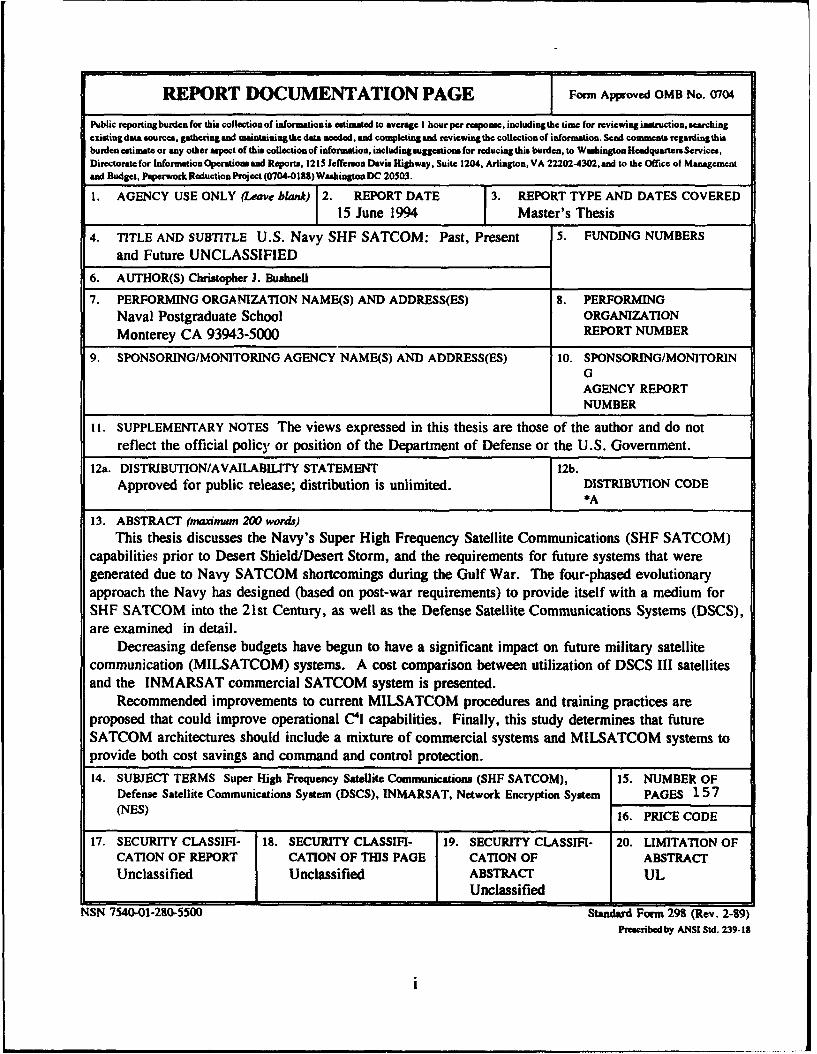
Figure 1. The Navy's Four Phase Evolutionary Approach to
SHF (NCCOSC, 1994, p. 1-3) .... ....... 2
Figure 2. MILSATCOM Requirements Survivability Hierarchy
(CJCS MOP 37, 1992, p. A-4) ..... ...... 4
Figure 3. Satellite Dish Throughput Comparison . . 20
Figure 4. Inter-Theater Global Grid (NCCOSC, 1994, pp.
4-3) .......... .................. .. 26
Figure 5. Defense Satellite Communication System I (DSCS
I) /Initial Defense Communication Satellite
Program (IDCSP) [Martin, 1991, p. 95] 28
Figure 6. Defense Satellite Communication System II
(DSCS II) (Martin, 1991, p. 100] . . .. 31
Figure 7. Defense Satellite Communications System III
(DSCS III) [Martin, 1991, p. 111] . . 36
Figure 8. DSCS Usage (Williams, 1994) ... ........ .. 40
Figure 9. DoD Plans for DSCS Constellation (GAO, 1993,
p. 10) ........ ................. .. 42
Figure 10. Revisions to DoD Plans for DSCS Constellation
(GAO, 1993, p. 11) ........ ........... 43
Figure 11. Tactical Entry Port Gateway vs. Direct
Connectivity (SPAWAR, 1994) ...... .. 45
Figure 12. DSCS Requirements Processing (DISA MSO Program
Plan, 1993, p. 2-23) ... .......... .. 56
xii

Figure 13. NES External Components .... .......... .. 62
Figure 14. Datagram Flow ........ .............. 64
Figure 15. Throughput Configuration ... ......... .. 67
Figure 16. Throughput in Packets per Second (Wade, 1993,
p. 7) ......... ................. 69
Figure 17. Throughput in Bits per Second (Wade, 1993, p.
7) .......... ................... .. 69
Figure 18. Latency Configuration (Wade, 1993, p.6) . . 71
Figure 19. Latency in Milliseconds (Wade, 1993, p. 8) 72
Figure 20. Peacetime Requirement Assignment (DISA MSO,
1994, p. 10) ........ ............. 79
Figure 21. CMRC Requirements Assignment (DISA MSO, 1994,
p. 11) .............. ................. 79
Figure 22. Navy.Use of INMARSAT (Hartung, 1994) . . . 85
Figure 23. QUICKSAT BLOCK DIAGRAM (SPAWAR, 1994, p.
14) ........... .................. 118
Figure 24. PHASE II BLOCK DIAGRAM (SPAWAR, 1994, p.
15) ........... .................. 119
Figure 25. PHASE III BLOCK DIAGRAM 'SPAWAR, 1994, p.
20) ........... .................. 120
xiii
I. INTRODUCTION
A. GENERAL
Operations Desert Shield and Desert Storm (DS/DS)
reinforced the requirement for and greatly accelerated the
introduction of the Navy's Super High Frequency Satellite
Communications (SHF SATCOM) capability on aircraft carriers
(CV/CVNs) and amphibious flagships. In order to satisfy
minimum tactical command, control, and warfighting
communications and intelligence requirements, dramatic
developments would have to be undertaken with regard to the
Navy's Military Satellite Communications (MILSATCOM)
architecture. (NCCOSC, 1994, p. 1-2) Figure 1 represents the
Navy's four phase SHF SATCOM program evolution that is
scheduled to occur between 1990 and 1996.
While the Navy's MILSATCOM architecture was formed on the
premise that no single satellite medium could satisfy all
operational requirements, SHF SATCOM was designated as the
primary communications medium for joint and Allied/North
Atlantic Treaty Organization (NATO) interoperability. (NCCOSC,
1994, p. 1-1) The remaining three communications services
incorporated in the Navy's MILSATCOM architecture are
Extremely High Frequency (EHF), Ultra High Frequency (UHF),
and commercial satellite systems.
1
Figur 1. Te Nay's Fur Phse EolutinaryAppoc%
SHF (CCOS, 194, p-1-3
2t.

Memorandum of Policy Number 37 (MOP 37) is the Chairman of
the Joint Chiefs of Staff (CJCS) document which establishes
operational policy, procedures and provides guidance on
MILSATCOM systems. MOP 37 also defines warfighting
requirements for MILSATCOM connectivity as either hard core,
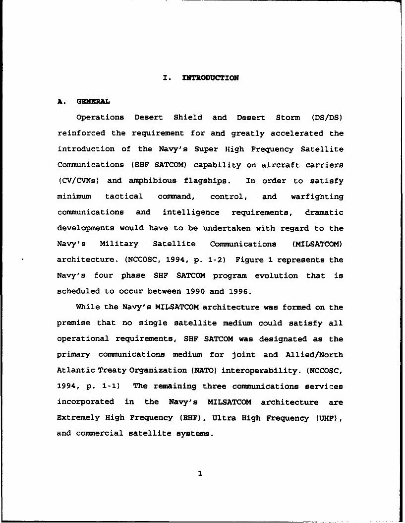
core or general purpose. An illustration of the applicability
of these terms to DoD missions is depicted in Figure 2. MOP
37 defines these terms in the following manner:
Hard Core - Supports critical command, con*communication and intelligence (C31) needs of the si4 eintegrated operational plan (SIOP), integrated tacticalwarning and attack assessment (ITW/AA), and nonstrategicnuclear forces (NSNF) iissions. Characteristics includesurvivability against the maximum threat for jamming,high-altitude electromagnetic pulse (HEMP) attack,scintillation, and includes low probability of intercept(LPI), low probability of detection (LPD), globalcoverage, and near-real-time access and networkreconfiguration.
Core - Provides communications connectivity to supporttheater/contingency operations, force projection, tacticalintelligence support, and counternarcotics requirements.Characteristics include survivability against a mediumthreat for jamming (tactical janmer) and limited LPI/LPD.
General Purpose - Provides communications connectivity tosupport day-to-day operations for logistic,administrative, intelligence, and common-user networks,and counternarcotics requirements, as well as non-DoDorganizations. (CJCS MOP 37, 1992, pp. GL-5 - GL-6)
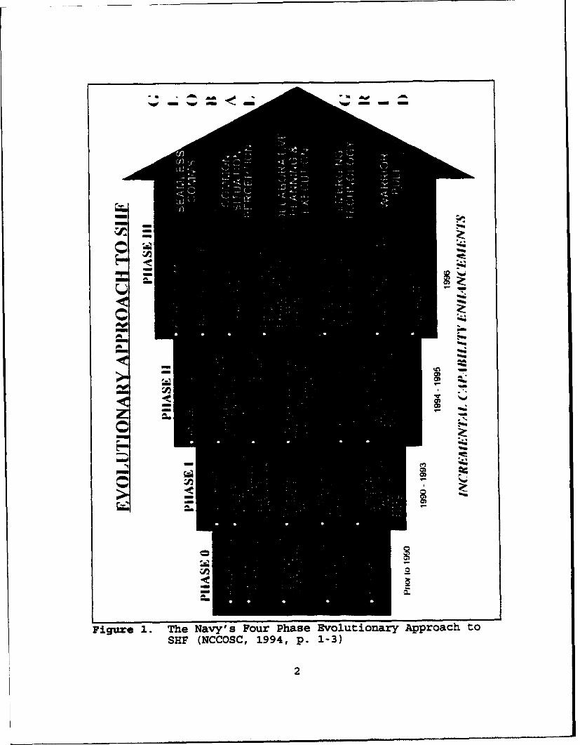
The MILSTAR Satellite encompasses the EHF communications
in the Navy's MILSATCOM architecture. MILSTAR can currently
provide low data rate (LDR) transmissions in the EHF frequency
band which serve to provide the primary protected, or hard
core communications service. Improvements are planned for
future MILSTAR satellites to support medium data rate (MDR)
3
transmissions which will provide high capacity "in-theater"
protected communications.
MILSATCOM Recuirements Survivability Hierarchy
"Hard' Core 'Soft* Core(Military) (Military)
Survivabilit yurvivaoili-7
ST,ACTI CAL FORCE 2
JTF C2 9E9t2 p. A4•iNNET N3NF1
ANTI- • u iipSINmTIL~LONi TRIAD ANUTIAbi
TheNavysmost ost effe 'rsateld TWc
SCporon Law
r General
Purpose(Commorciall/Military Mix)LowSurvivability
Figure 2. MILSATCOM Requirements Survivability Hierarchy(CJCS MOP 37, 1992, p. A-4)
The Navy's most cost effective satellite coulmmication
systems are those which provide communications in the UHF
frequency range. These systems make up the worldwide backbone
for unprotected and general purpose military communications.
4

Commercial satellite communication systems serve to
provide a "surge" capacity for the military when MILSATCOM
assets are either overburdened or not available due to the
physical constraints of orbital mechanics. The SATCOM
services provided by commercial satellite systems are
unprotected general purpose communications.
The Defense Satellite Communications Systems (DSCS) serves
as the MILSATCOM system that provides high capacity, core and
general purpose communications to tactical users in the SHF
frequency band. The Navy's SHF SATCOM program is the focus of
this report.
B. SCOPE
The goal of this study is to provide an in-depth
examination of the Navy's SHF SATCOM program before, during,
and after Desert Shield/Desert Storm. Additionally this
thesis provides insight into the political discussions going
on between Congress and DoD over future developments in
military satellite communications and the application of
commercial satellite systems in the MILSATCOM architecture.
C. ORGANIZATION
This document is organized into seven chapters. The first
chapter describes the purpose of this thesis and provides
general background information on the Navy's SHF SATCOM
program. The second chapter provides the reader with a
5

complete overview of the Navy's SHF capabilities prior to
Desert Shield/Desert Storm, and the requirements that were
generated for future systems due to Navy SATCOM shortcomings
during the Gulf War. The third chapter discusses the four-
phased evolutionary approach the Navy has designed to provide
itself with a medium for SHF SATCOM into the 21st Century. In
Chapter IV the Defense Satellite Communications System (DSCS)
is described in detail from its initial design to current
operating status. Chapter IV closes with a description of
possible DSCS follow-on programs. The fifth chapter
introduce3 the network encryption system (NES) as a means to
migrate fixed-site-to-fixed-site DSCS SATCOM transmissions to
terrestrial fiber optic networks. Chapter VI discusses
studies and applications of commercial satellite systems in
the MILSATCOM architecture. Additionally, Chapter VI provides
a cost comparison between the annual operating costs of a
single DSCS III satellite and the fees the Navy pays for
INMARSAT connectivity for one year. The final chapter
provides conclusions and recommendations to problems that
surfaced during the examination of this program.
6

I1. HISTORY OF NAVY SHK SATCCO(
A. INTRODUCTION
Prior to the development of satellites, the Javy relied on
semaphore, flashing light, flag-hoist signals, Ultra High
Frequency (UHF) line of sight, and High Frequency (HF) surface
wave signals for communication. The advent of satellite
communications (SATCOM) for the Navy first came through
leasing commercial communication satellites that had been
placed in orbit over the Atlantic, Pacific and Indian Oceans
in the mid 1970s. These satellites covered the UHF spectrum,
and the program these satellites were leased under was called
the Maritime Satellite (MARISAT) Program. The leased MARISAT
assets were later given the name GAPFILLER. (NOSC, 1991, p.
93) Additional UHF satellite capabilities were later provided
by the Fleet Satellite Communication (FLTSATCOM) program in
the late 1970s, the Leased Satellite (LEASAT) program in the
early 1980s and the UHF Follow-On (UFO) program in the early
1990s. (NOSC, 1991, pp. 93-101) Due to bandwidth
considerations and the need to support strategic wgeneral
purpose, core, and hard core" requirements, the Navy Super
High Frequency Satellite Communications (SHF SATCOM) program
was initiated in 1971. It was determined that the Defense
Satellite Communications System (DSCS) would be utilized as
7

the space segment, since the Department of Defense (DoD) had
been experimenting with this orbiting constellation since 1968
to satisfy DoD communication "needs." (Aerospace, 1991, p.
100)
1. Initial Requirements
The initial requirements for the SHF SATCOM capability
started in 1971 were to provide a robust, Anti-Jam (AJ)
protected, ship/shore/ship conmnunications service. Specific
data rates were not mandated, the driving force was simply to
have to capability to communicate through SHF communications
via satellite.
2. Initial Systems
The first SHF shipboard terminals were the AN/SSC-6
and AN/WSC-2 Terminals. These terminals have since been
replaced by the AN/WSC-6(V) Terminal. AJ-protected
communications service was provided by the OM-55(V)/USC
Pseudo-Noise (PN) spread spectrum modulation subsystem which,
in the late 1970's, was made interoperable with the Army
AN/USC-28(V) spread spectrum modulation subsystem within the
Defense Satellite Communications System (DSCS) Electronic
Counter-Counter Measure (ECCM) network. (ACS, 1994, p. 2-8)
B. PHASE 0: AN/WSC-6(V)I,2 AND AN/SSC-6
In 1976, the need for high-capacity SHF satellite
communications was identified for the Surveillance Towed Array
Sensor System (SURTASS) operational mission. SURTASS ships
8

are basically "submarine hunters" that use advanced towed
array sonar systems. This period of time marked the mid-point
of the "Cold War," thus the current application of SHF SATCOM
was primarily "strategic" in nature only.
1. Phase 0 Requirements
A letter from the Office of the Chief of Naval
Operations (CNO) in June 1976 stated an operational
requirement to provide an SHF SATCOM capability for the
SURTASS T-AGOS ships and Navy combatant and Fleet Flagships.
(CNO Letter, 14 June 1976; ACS, 1994, pp. 2-8; SPAWAR, 1994,
p. 3) The operational requirements for the Navy SHF SATCOM
systems in 1976 were: the system had to be jam resistant,
provide for a single carrier, have a Mean Time Between
Failures (MTBF) for the antenna greater than or equal to 1300
hours, MTBF for the radio greater than or equal to 900 hours,
MTBF for the modem greater than or equal to 1200 hours, have
a Mean Time To Repair (MTTR) for the antenna less than or
equal to eight hours, MTTR for the radio less than or equal to
five hours, MTTR for the modem less than or equal to four
hours, have an operational availability of 0.94, and be able
to initially support data rates of 32 kbps with expansion to
64 kbps. (SPAWAR, 1994, p. 9) This trend towards "high-
capacity" SHF SATCOM communication would continue on into the
next century. Typical circuit loading utilized by the
SURTASS platforms was a 64 kbps ship-shore SURTASS data link
9
and a 1.35 kbps full duplex Orderwire circuit. The Fleet
Flagship's data rates vary from platform to platform ranging
from 16 kbps to 52 kbps. Circuits employed by these vessels
included: Worldwide Military Command and Control System
(WWMCCS) at 2400 kbps, Contingency Theater Automated Planning
System (CTAPS) at 2400 kbps, Secure Telephone Unit-Third
Edition (STU-III) at 2400 kbps, Advanced Narrowband Digital
Voice Terminal (ANDVT) at 2400 kbps, and Orderwire and
Teletype at 75 bps. (SPAWAR, 1993, p. 6)
2. Phase 0 Systems
The first shipboard SHF installation was in 1974 on a
SURTASS T-AGOS platform, but this conducted as a result of the
effort started in 1971. The direct result of the CNO's letter
stating the operational requirement was the installation of 25
SHF SATCOM systems. Specifically these 25 were: 18 AN/WSC-
6(V)l terminals on SURTASS T-AGOS ships, 1 AN/SSC-6
(forerunner of AN/WSC-6(V)2) on the flagship USS LASALLE, 5
AN/WSC-6(V)2 terminals on Navy fleet flagships (USS CORONADO,
USS BLUE RIDGE, USS MT. WHITNEY, USS BELKNAP, and USS NASSAU),
and one AN/WSC-6(V)2 terminal was installed at the Fleet
Training Center (FTC), Norfolk, VA. (ACS, 1994, p. 2-8;
SPAWAR, 1993, p. 5)
The technical characteristics of the three different
variants of Phase 0 included different combinations of antenna
groups, radio groups and modems.
10

a. ANIWSC- 6 (V) 1
This variant utilizes the OE-279 Antenna Group, as
do the other two. It uses the OZ-43 Radio Group, which
includes an 8 KW High Power Amplifier (HPA), and the MD-1030A
Modem.
b. AN/SSC- 6
Variant two shares the same OE-279 Antenna Group
as the AN/WSC-6(V)l,2. The Radio Group is unnomenclatured,
and employs the OM-55(V) modem for jam resistant secure
communications.
c. AN/JSC-6(V)2
Variant three of Phase 0 shares the common OE-279
Antenna Group and OZ-43 Radio Group, which includes an 8 KW
HPA. Since AN/SSC-6 in the forerunner of the AN/WSC-(V)2,
they share the same OM-55(V) modem. (SPAWAR, 1993, p. 5)
C. SHF SATCOM POST DESERT SHIELD/DESERT STORM
The Phase 0 SHF SATCOM variants remained the status quo
for the Navy until 02 August 1990 when Iraq invaded Kuwait.
Operation Desert Shield/Desert Storm (DS/DS) demonstrated the
need for the Navy to have more communications "pipes" for all
types of information, as well as connectivity between all
operational forces. The other services were using SHF because
of its wide bandwidth, which makes it ideal for data
transmission, and also because it is inherently more jam
resistant than Ultra High Frequency (UHF) transmissions. The
11
Navy deemed that it was necessary to improve current SHF
SATCOM capabilities "to satisfy minimum tactical command and
control, intelligence and war-fighting communications
requirements, and improve Joint and Allied/NATO communications
interoperability." (NAVSPACECOM, 1992, pp. 1-2) One glaring
example of how an improved SHF SATCOM capability would have
helped the Navy during the Gulf War is how it could have
helped eliminate the problems associated with dissemination of
the Air Tasking Order (ATO).
1. Post Gulf War Requirements
Desert Shield/Desert Storm transformed the Navy's
usage of SHF SATCOM from a "strategic" to a "tactical" nature
and provided the impetus for a rapid increase in the numbers
of SHF SATCOM terminals in the fleet. Recognizing the need
for an improved SHF SATCOM capability, the Office of the CNO
mandated the accelerated fielding of SHF shipboard terminals
in August 1990. (CNO Letter, 28 August 1990) As a result of
this order, the Navy's use of DSCS expanded significantly over
the next few years.
The operational requirements of the improved SHF
SATCOM system tie Navy was seeking were vastly different from
those SATCOM systems that the Navy had been operating since
1974. Operational requirements as of 1992 were: the system
must be able to support multiple carriers; MTBF for the system
300-1200 hours; MTTR for the system 2.5-7 hours; operational
12

availability of 0.85-0.98; be able to support data rates of up
to 640 kbps; have a modular design to permit future component
level upgrades as component technology improves; and be able
to support pre-planned product improvement (P 31) for data
rates of T1 (1.544 Mbps) and El (2.048 Mbps) . (SPAWAR, 1994,
p. 10)
13

III. SEF SATCOM TERMINAL IMPROVEMENT
The SHF SATCOM terminal improvements that were deemed
necessary as a result of the shortcomings of the Navy's SHF
SATCOM capabilities during Desert Shield/Desert Storm were
programmed to be completed in an incremental evolution process
totaling three phases. The AN/WSC-6(V) terminals that were
installed on the SURTASS platforms and Fleet Flagships are not
one of the phased improvements, but those variants were
recognized as Phase 0 installations. Upon the completion of
the three phase process, a significantly improved SHF SATCOM
capability will be installed on most naval combatants. (ACS,
1994, p. 2-8)
A. PHASE I: QUICKSAT
To meet the urgent joint interoperabliity requirement to
satisfy minimum tactical command, control, communications and
intelligence (C3 I), war-fighting communications, and high data
rate communications, the Navy obtained and modified U.S. Air
Force (USAF), Army, and Marine Corps AN/TSC-93B Ground Mobile
Force (GMF) SHF SATCOM equipment. Modifications to the vans
were limited to use of the standard Navy SHF antenna system,
the SURTASS digital modem, two low speed time division
multiplexers (LSTDMs), and additional patch panels. The
modified SATCOM vans and racked equipment were designated
14

"QUICKSAT." The introduction of these terminals into the
fleet marked the beginning of Phase I of the Navy's SHF SATCOM
fielding plan. The objective was to quickly provide the
maximum capability with the highest probability of success.
In meeting its goal of increased and responsive command,
control, communications, computers and intelligence (C4 I)
support to operational war fighters, the Navy relied
increasingly on selected commercial off-the-shelf (COTS)
equipment. (NCCOSC, 1994, pp. 1-2)
QUICKSAT was to provide a diverse range of host systems.
These host systems services include voice, narrative text,
database transactions, graphics, bit-mapped imagery, video,
and combinations of those listed. A more detailed description
of the hosted systems is included in Appendix B.
The original intention of the QUICKSAT program was to have
five ships outfitted with "borrowed" equipment on an interim
basis so that these five SHF SATCOM systems would be
operational during DS/DS. The first QUICKSAT system
(installed in USS Tarawa) was actually not operational until
after DS/DS, and the "interim" program has now been installed
on thirteen ships. (Martin, 06 April 1994) The initial units
were installed in the form of deck-mounted terminal vans on
the "island" superstructure, and the later installations were
in a rack-mounted terminal within the superstructure. The
single four foot stabilized tracking antenna was mounted high
on the "island" superstructure to minimize structural
15

masking/blockage and mutual radio frequency interference
(RFI). QUICKSAT utilized two configurations, one utilizing
"borrowed" equipment from other services, and the later
installations used purchased equipment. The "borrowed"
configuration employed the AN/TSC-93B radio, a Navy OE-279
antenna group, and an MD-1030A modem. The later
installations utilized the AN/WSC-6(V) radio group, Navy OE-
279 antenna group, and MD-l030A modem. (SPAWAR, 1993, p. 7)
A basic block diagram of the QUICKSAT system is enclosed in
Appendix C. The QUICKSAT van is powered electrically from
shipboard systems, and has a dedicated external air
conditioning system for cooling purposes. Two of the QUICKSAT
installations (USS Nimitz and USS Wasp) replaced the AN/WSC-
6(V) radio group with the AN/WSC-6(V)2. This version of the
radio group contains a medium power amplifier (MPA) [300
Watts] instead a high power amplifier (HPA). This adjustment
was made due to the air conditioning units experiencing
difficulties with dissipating heat from the HPAs. Space
limitations would not allow for a larger cooling system which
was deemed necessary if HPAs were to be kept.
The QUICKSAT installation was completed on aircraft
carriers (CV/CVNs) and selected "L" class ships (Amphibious
Assault Ship - LHA, Landing Platform Helicopter Ship - LPH,
and the Multi-purpose Amphibious Assault Ship - LHD). The
three phase evolution of the SHF SATCOM architecture for the
Navy mandates that the amphibious ships maintain QUICKSAT as
16

their SHF capability until Phase III is implemented, and the
only platforms that will receive Phase II will be the CV/CVNs.
(SPAWAR, 1993, p. 11)
B. PHASE II: AN/WSC-6(v)4
Commencing in Fiscal Year (FY) 1994, Phase II of the SHF
SATCOM evolution plan started replacing QUICKSAT terminals on
CV/CVNs with AN/WSC-6(V) terminals. In an effort to reduce
system costs, Non-Developmental Item (NDI) technology began to
be utilized in the Phase II installations. Use of NDI
technology was also chosen to help minimize the delay of the
advanced service to the fleet by taking advantage of
components that were available commercially off the shelf
(COTS) and had depot support and documentation to back them
up, as well as increase the data rate capability from 50 kbps
to 256 kbps. The two major components that were provided
through the NDI approach were the 300 Watt Traveling Wave Tube
(TWT) Medium Power Amplifier (MPA) and the Stanford
Telecommunications (STel) 1105 Demand Assigned Multiple Access
(DAMA) Time Division Multiple Access (TDMA) modem. A basic
block diagram of the Phase II system is enclosed in Appendix
C. Another modification that will be introduced with Phase II
is the seven foot antenna. The larger antenna will support
higher data rates as a result of improved gain and signal
quality. Cost estimates for a Phase II system using a four
foot antenna without NDI technology are approximately $2.5
17

million per system, while the seven foot antenna system
without NDI technology would cost approximately $3.5 million.
Market estimates for an NDI system with a 7 foot antenna are
approximately $1.9 million. This apparent savings coupled
with the fact that the three phase plan calls to outfit 150
ships (but Congress has only allocated funding for 32)
suggests that the NDI approach is the trend of the future.
(Martin, 01 February 1994)
The CV/CVNs are being retrofitted with the STel 1105 TDMA
modem, a generic Bi-phase Shift Keying (BPSK) modem, and
Timeplex TDMA multiplexer. The decision to utilize the Stel
1105 modem was made in late 1990-early 1991 over another
competitive model. Not only was the Stel 1105 modem cheaper.
but it was a reliable system. The Stel 1105 had proven to be
an excellent performer for numerous years while being employed
in "black" programs for intelligence agencies. The Navy
purchased 35 Stel 1105 modems (at approximately $65K per
copy), 26 of which came from previous acquisitions through
"black" programs, but does not plan to buy any more.
Frequency division multiple access (FDMA) modems which could
accommodate the same data rates cost approximately $10k. The
reason for the higher cost of the TDMA modems is due to the
precision timing requirements associated with the components
controlling time division multiplexing. While QUICKSAT's use
of the 1030 modem and FCC 100 multiplexer were based on the
needs of the Navy in late 1991-early 1992, the needs
18

changed/increased, and have continued to do so. Originally
the STel 1105 modem was designed for use with five or six
ships operating at 16 kbps apiece (256 kbps aggregate). Now
a single ship can run 256 kbps; hence the STel 1105 B and C,
which can handle up to 5 Mbps. (Martin, 06 April 1994) Phase
II installations have been tested and have proved the
capabilities of the STel modem in Tandem Thrust 92, Ulchi
Focus Lens 92 (Defense of Korea) and Secure Tactical Data
Network Four (STDN4) demonstration held in September 1993.
There is significant disagreement between the services and
the Defense Satellite Communications System (DSCS) system
manager, Defense Information System Agency (DISA), over how to
more efficiently utilize the SATCOM assets (DSCS). The Navy
is uniquely at a disadvantage relative to the other services
in that the Navy platforms that require SHF SATCOM service are
continuously mobile while maintaining communications. The
Ground Mobile Force (GMF) users are only tasked with
maintaining communications while their SHF SATCOM site is in
a fixed location. If the GMF user is tasked with shifting
locations, they either shift the "guard" for the SHF circuit
to another fixed unit, or drop out of the SHF SATCOM
communications grid completely until they have shifted and set
up their SATCOM capability again. This, coupled with the fact
that the size of the antenna the Navy uses is four feet
instead of the eight or 20 foot antenna used by G4MF users and
the 40 and 60 foot medium and heavy terminals used by larger
19

facilities. This disadvantage is demonstrated by the
significantly smaller throughput values encountered by Naval
forces utilizing SHF SATCOM in Figure 3.
U
4 K ........ * ....... ....... -----............. *.............. . . . . . . . . . . . . . . . . . . . . . . . . . . . . . . . . . . . . . . . . .
ftds
p
DllWle NMiy4ft Nsiy4* OMMFi GWt A2ft WTOft WIIORf
A 101 l5011 IS 01" aS 3Tr(T MQ3T
Figure 3. Satellite Dish Throughput Comparison
Because of these disadvantages the Navy requires higher
power, either on the ship or on the DSCS satellite. Other
ways to possibly alleviate this problem are to increase DSCS
power, put larger antennae on ships, or utilize beam forming
networks on the satellites. The Navy is in the process of
increasing the size of the antennae on the ships by
introducing the seven foot antenna with the Phase II
20

installation. Other possible future modifications to the DSCS
satellites will be discussed in Chapter IV.
1. DISA DAM& Standard
In April 1992 the Military Communication Electronics
Board (MCEB) tasked the Defense Information Systems Agency
(DISA) with preparing a standard for SHF DAMA. The objectives
of developing a standard were to ensure more efficient use of
DSCS satellite resources, ensure interoperability between all
users (as mandated by C4 IFTW [J61, 1993]), support all user
platforms, as well as support all user service requirements.
The self-imposed constraints that DISA was operating under in
the development of the DISA DAMA Standard were: the standard
had to be a direct derivative of commercial DAMA practices; be
an open-ended standard that would allow for evolving
technology; operate in X(DSCS), C, and Ku bands; and also be
inexpensive. (DISA, 1994, pp. 1-4)
The requirement for increased throughput led Navy
engineers to begin pursuing SHF DAMA as a solution in early
1990. A market survey conducted in 1991 revealed only two
available NDI DAMA modems that would be candidates for the
Navy. As previously discussed, it was determined in October
of 1991 that the STel 1105A was the most cost-effective choice
for DAMA modems, so in early April of 1992, the Navy acquired
shore 1105A modems from STel. (SPAWAR, 1994, p. 10)
21

DISA established the first government/industry SHF
DAMA Standard Working Group, and held its first meeting in
June of 1992. The first draft of the DISA DAMA Standard was
presented by the working group for government/industry review
in January of 1993, and a second draft was again presented in
May of 1993. The "final draft" of the SHF DAMA Standard was
released on 30 September 1993, over three years after the Navy
had begun pursing DAMA modems as an answer for more efficient
use of DSCS. DISA does not anticipate publishing the final
SHF DAMA Standard until September of 1995. (SPAWAR, 1994, p.
10)
In order to compensate for the "late" development of
a DAMA Standard after the Navy had begun procuring modems to
help solve the problem, DISA wrote the standard to include two
profiles.
a. Profile 1
This standard includes a requirement for a common
control element and a basic communications package. This
profile is mandatory for all new terminals. The network
control terminal (NCT) governing the network will have the
ability to control the bandwidth and power usage of
participating users. This configuration will employ backward
compatibility with existing SHF DAMA modems.
22

b. Profile 2
This is the category that the was written into the
standard to "cover" the Navy's TDMA DAMA modem. This standard
shares the same common control element and basic
communications package as Profile 1, but also has an
additional expanded communications capability. This is to
allow for future mission and user needs, as well as technology
insertion. There are additional capabilities beyond that of
Profile 1 that are written into the second profile
specification that are Navy specific.
C. PUASE III: AN/WSC-6(V)XX
Phase III of the SHF SATCOM evolution process is scheduled
to begin in FY 1997. This phase will deploy the next AN/WSC-6
variant in three configurations. Configuration A is
applicable to major Fleet Flagships, Battle Force/Battle Group
Flagships (CV/CVNs), and major amphibious force flagships.
Configuration B is applicable to selected cruisers/destroyer
(Tomahawk capable platforms) selected amphibious ships,
selected Combat Logistics Force (CLF) ships, and maritime
prepositioning ships. Configuration C is applicable to
SURTASS ships. (NRaD, 1993, p. 7) The new terminal will be a
modern, modular open architecture terminal capable of
providing a full spectrum of SHF SATCOM communication
services. (NCCOSC, 1994, p. 4-1)
23

1. Standard Tactical Entry Point (STEP)
The current SHF SATCOM architecture utilizes a hub and
spoke network for QUICKSAT operations. There are five
QUICKSAT Satellite Communication Facilities worldwide which
act as terminal entry points (gateways) or hubs. The five
locations are: Northwest, Virginia; Wahiawa, Hawaii; Fort
Buckner, Okinawa, Japan; Lago di Patria, Italy; and Finegayan,
Guam. (SPAWAR, 1994) These five tactical entry points have
unique configurations an-I requirements and are limited in
capacity and capability. These differences often cause
problems as Naval forces move from one area of operations to
another. To help eliminate this problem the Navy has planned
to implement the Standard Tactical Entry Point (STEP). The
STEP will provide Navy and other users uniform, seamless, and
transparent access to the DoD's envisioned Global Grid. It
will also ensure efficient bandwidth use, indirect
interoperability, no idle bandwidth, and low management
overhead. (NCCOSC, 1994, p. 4-1)
2. Global Grid
Implementation of the STEP and Phase III will allow
the Navy connectivity to the Global Grid envisioned by DoD,
which will provide "plug and play" voice, data, imagery, and
video among all services. This Worldwide DoD/Joint
Communications Network will support data rates into the Giga
bits per second (Gbps), utilizing Asynchronous Transfer Mode
24
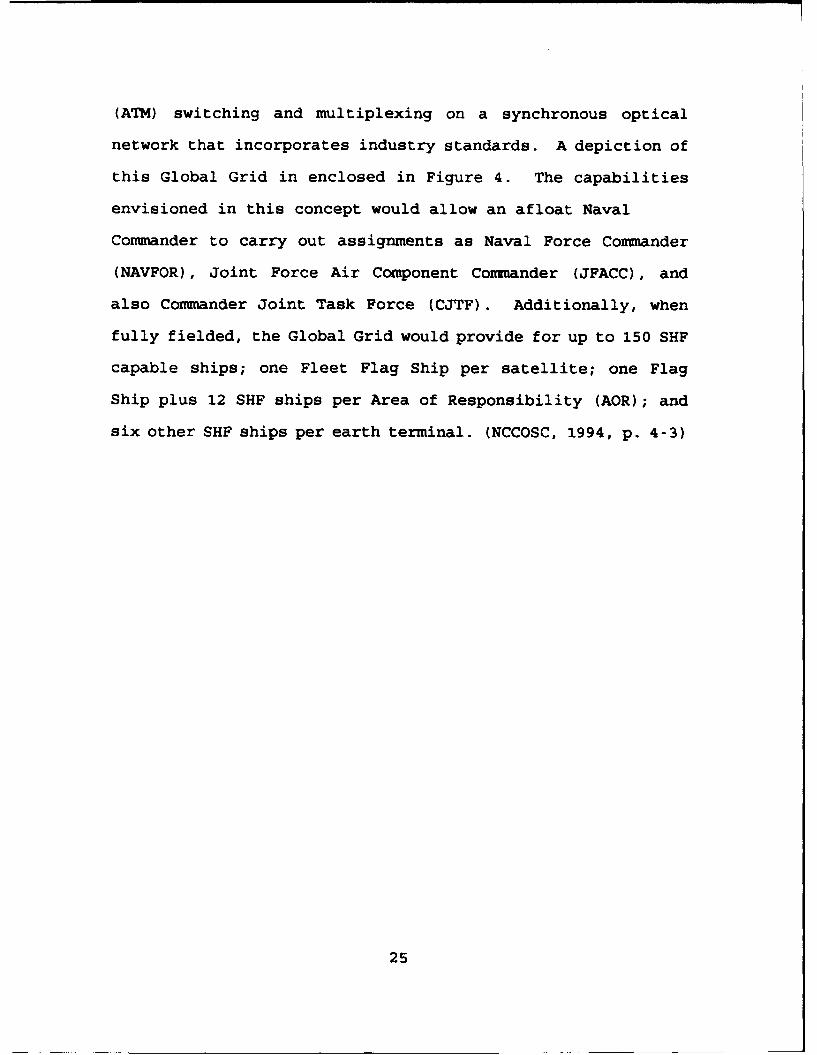
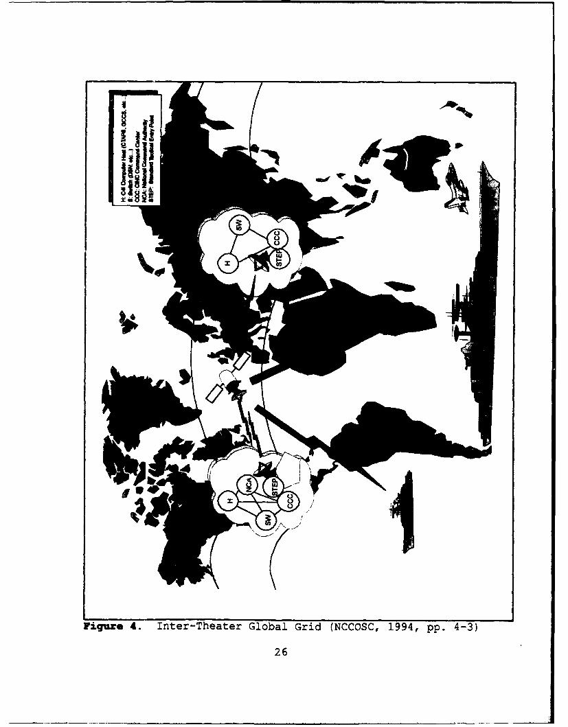
(ATM) switching and multiplexing on a synchronous optical
network that incorporates industry standards. A depiction of
this Global Grid in enclosed in Figure 4. The capabilities
envisioned in this concept would allow an afloat Naval
Commander to carry out assignments as Naval Force Commander
(NAVFOR), Joint Force Air Component Commander (JFACC), and
also Commander Joint Task Force (CJTF). Additionally, when
fully fielded, the Global Grid would provide for up to 150 SHF
capable ships; one Fleet Flag Ship per satellite; one Flag
Ship plus 12 SHF ships per Area of Responsibility (AOR); and
six other SHF ships per earth terminal. (NCCOSC, 1994, p. 4-3)
25
iu
Figure 4. Inter-Theater Global Grid (NCCOSC, 1994, pp. 4-3)
26

IV. DEFENSE SATELLITE COINKUNICATIONS SYSTEM BASICS
The Defense Satellite Communications System (DSCS) is
designed to provide vital, long-haul, and high volume
communications service to U.S. forces and validated non-DoD
users throughout the world. The current DSCS system is
composed of three segments: the control segment, the terminal
segment, and the space segment. The control segment is
dominated by U.S. Army operated facilities in Fort Meade, MD;
Fort Detrick, MD; Fort Buckner, Okinawa; and Landstuhl,
Germany. The Navy's terminal segment consists of the AN/WSC-6
and AN/TSC-93B terminals, which were discussed in Chapter III.
The DSCS SHF SATCOM space segment consists of the Department
of Defense (DoD) DSCS satellite constellation. This
constellation has evolved through three different variants
(DSCS I, DSCS II, and DSCS III) since the Advanced Research
Projects Agency (ARPA) undertook an effort to provide an
operational military communication satellite in April 1960.
(Martin, 1991, p. 95)
A. DEFENSE SATELLITE CONKUNICATIONS SYSTEM I
1. Initial Defense Conmunication Satellite Program
(IDCSP)
The Defense Satellite Communications System I (DSCS I)
program was originally called the Initial Defense
Communication Satellite Program (IDCSP). An artist's
27

rendering of the DSCS I/IDCSP is depicted in Figure 5. The
IDCSP program began in 1962 when the Advent program, which was
the program ARPA began in 1960, was cancelled. The Titan
III-C rocket was selected as the IDCSP launch vehicle, and the
first successful launch of the IDCSP into a subsynchronous
orbit was completed in June 1966. Additional satellites were
launched in 1967 and 1968, placing 26 of 34 satellites
launched successfully into orbit. (Martin, 1991, pp. 95-96)
N /
Figure 5. Defense Satellite Communication System I (DSCS I)/Initial Defense Communication Satellite Program(IDCSP) [Martin, 1991, p. 95]
28

2. Satellite Operations
The IDCSP was a very simple, spin-stabilized,
subsynchronous satellite, with neither a stationkeeping or
altitude control capability. The design engineers of the
satellite (Ford Aerospace and Communications Corporation)
determined no command systems were to be included in the
constellation, as command system failures had led to the
termination of the Advent program and terminated operations of
the Courier and Telstar 1 satellites. Additionally, the
randomness of the individual satellite orbits provided for
automatic replacement of failed satellites with acceptable
outages. (Martin, 1991, p. 95) Satellite design details and
specifications are included in Appendix D.
In 1967, the war in Vietnam led to the IDCSP being
used as an operational communication link for high-speed,
digital data transmission from Vietnam to Washington, D.C.,
via Hawaii. (Martin, 1991, p. 96) The system was declared
operational in 1968, and the name of the program was again
changed to Initial Defense Satellite Communication System
(IDSCS). Though the name was never "officially" changed to
DSCS I, it has come to be known as this amongst satellite
communications experts. The overall reliability of the DSCS
I program was much beyond the original expectations of the
designing engineers. The actual Mean Time Before Failure
(MTBF) achieved was more than double the design life of three
29
years. The last DSCS I satellite was removed from service in
1977. (Martin, 1991, p. 96)
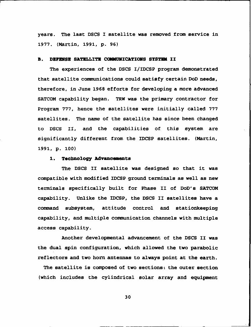
B. DEFENSE SATELLITE CONUNICATIONS SYSTU II
The experiences of the DSCS I/IDCSP program demonstrated
that satellite communications could satisfy certain DoD needs,
therefore, in June 1968 efforts for developing a more advanced
SATCOM capability began. TRW was the primary contractor for
Program 777, hence the satellites were initially called 777
satellites. The name of the satellite has since been changed
to DSCS II, and the capabilities of this system are
significantly different from the IDCSP satellites. (Martin,
1991, p. 100)
1. Technology Advancements
The DSCS II satellite was designed so that it was
compatible with modified IDCSP ground terminals as well as new
terminals specifically built for Phase II of DoD's SATCOM
capability. Unlike the IDCSP, the DSCS II satellites have a
command subsystem, attitude control and stationkeeping
capability, and multiple communication channels with multiple
access capability.
Another developmental advancement of the DSCS II was
the dual spin configuration, which allowed the two parabolic
reflectors and two horn antennas to always point at the earth.
The satellite is composed of two sections: the outer section
(which includes the cylindrical solar array and equipment
30

platform), and the inner section (which houses all the
communications equipment and antenna). The outer section was
designed to spin to stabilize the satellite, while a motor and
bearing assembly effectively isolates the inner section by
despinning it. This despinning action is what allows the
antennas to always point at the earth. (Martin, 1991, p. 100)
Nn artist's rendering of the DSCS II is depicted in Figure 6.
Figure 6. Defense Satellite Communication System II (DSCSII) [Martin, 1991, p. 100]
31

2. Satellite Operations
The first pair of DSCS II satellites were launched by
a Titan III-C rocket in November 1971. Of the 16 DSCS II
"birds" lauched between November 1977 and October 1982, 12
achieved the designed synchronous orbit and provided service
for some time. The first 14 DSCS II birds were launched in
pairs. The 15th and 16th DSCS II satellites were launched in
tandem with DSCS III birds. The launch platform for these
launches was the Titan 34-D.
The last 10 DSCS II satellites were modified so that
one narrowbeam antenna is "defocused" to provide area coverage
of nominally six degrees of bandwidth. These satellites were
launched to establish and maintain an orbital system of four
active and two spare satellites. The last four satellites
were upgraded to include 40 Watt Traveling Wave Tubes (TWTs)
instead of the originally installed 20 Watt TWTs. (Martin,
1991, p. 102)
3. Cowaunication Subsystm
The DSCS II satellite has a communication subsystem
comprised of four channels. This subsystem includes
redundant, sophisticated combinations of tunnel diode
preamplifiers, single-frequency conversion, tunnel diode
amplifiers (TDAs), and driver and high power TWTs. (Martin,
1991, p. 102)
32

a. Channel 1
Channel 1 transmits in the 7250 to 7375 MHz
frequency range. Both the receive and transmit antennas
provide earth coverage.
b. Channel 2
Channel 2 transmits in the 7400 to 7450 MHz
frequency range. The transmit antenna provides earth
coverage. The receive antenna provides narrowbeam or earth
coverage (on satellites 7-16).
c. Channel 3
Channel 3 transmits in the 7490 to 7675 MHz
frequency range. The transmission and receive antennas of
satellites 1 through 6 both provide narrowbeam coverage.
Upgrades to satellites 7 through 16 allow for either
narrowbeam or earth coverage on the transmission and receive
antennas.
d. Channel 4
Channel 4 transmits in the 7700 to 7750 MHz range.
The receive antenna provides earth coverage. The transmit
antenna provides narrowbeam or earth coverage (on satellites
7-16).' [Martin, 1991, pp. 101-102]
1 Additional technical specifications on the DSCS IIsatellite are enclosed in Appendix D.
33
4. Constellation Life Cycle Management
The designed life cycle of the DSCS II satellites was
five years. Due to inadvertant over-engineering of the solar
arrays (caused by an error in the model used to help design
the solar arrays), the actual life expectancy of a DSCS II
bird has averaged approximately 12 years. (Williams, 1994) As
the older satellites become degraded, they are replaced with
another satellite to act as the "primary" communications
satellite. The degraded satellite then assumes the role of a
"back-up" system. Once the constellation is so degraded that
it is no longer useful, it is maneuvered out of the
synchronous orbit with the stationkeeping thrusters. The last
DSCS II satellite acting as a "primary" communication
satellite was replaced with a DSCS III bird in March 1994.
(Williams, 1994)
C. DIVENSE SATELLITE CONKUNICATIONS SYSTDM III
As the DSCS system has evolved, there has been a
significant increase in both the number and variety of
terminals. The system that was originally planned for long-
distance communications between major military locations was
now being adapted to be used by GMF users needing
transportable terminals, or mounted on ships to provide SHF
communications connectivity to deployed Naval forces. The
Defense Satellite Communications System III (DSCS III) was
34

developed to operate in this diverse environment. (Martin,
1991, p. 111)
1. Program Inception
Design studies and breadboard systems of certain
components of the DSCS III satellite were being conducted by
General Electric Astro Space in 1976. The major advancement
that was requiring the most study was the development of the
Multi-Beam Antenna (MBA). Final development of the DSCS III
qualification model and two flight models began in 1977. The
first of these three DSCS III Block A satellites was launched
in October with a DSCS II bird. The program plan of DSCS III
is to establish and maintain an orbital constellation of at
least five active and two spare satellites. (Martin, 1991, p.
113)
2. Satellite Components
The DSCS III satellite has a rectangular body
approximately six feet x six feet x 10 feet. Attached to the
main body of the satellite are two solar arrays, which deploy
from the north and south faces of the satellite to an overall
length of 38 feet. All support subsystems except the solar
arrays are contained within the body. See Figure 7 for an
artist's rendering of the DSCS III antenna.
3. Primary Communication Subsystem
There are eight antennas on the primary comuunication
subsystem of the constellation that can be configured in
35

various ways to six transponders. The eight antennas include:
one 45-inch receive MBA, two 28-inch transmit MBAs, one 33-
inch gimbaled dish antenna (GDA) for transmission, and four
horn antennas (two for receive and two for transmission).
(Martin, 1991, p. 111)
Figure 7. Defense Satellite Communications System III (DSCS
III) [Martin, 1991, p. 111]
The six transponders on the satellite are unique in
that they have their own limiter, mixer, and transmitter.
This feature allows the transponders to be configured to be
used with either Frequency Division Multiple Access (FDMA) or
Time Division Multiple Access (TDMA) transmissions.
Additionally, the transponders can be configured to choose
36

between receiving antenna, transmitting antenna, and
transponder gain level. (Martin, 1991, p. 111) The 45-inch
receive MBA can form a beam of variable size, shape and
location by means of a beam forming network that controls the
amplitudes and phases of each of the individual 61 beams.
Four of the six transponders can be connected to this antenna.
The MBA also has the ability to form nulls in selected
areas/directions to counter jamming. (Martin, 1991, p. 111)
The two receive horn antennas are earth coverage antennas.
The two 28-inch transmit MBA have the same
capabilities as the receive MBA, with the exception of
nulling. There are also only 19 individual beams on these
antennas, which may be connected to four transponders. The
remaining two transponders are always connected to the two
transmit earth coverage horn antennas. Three transponders may
be switched to the 33-inch GDA, which generates a single beam
with high EIRP. (Martin, 1991, pp. 111-112)
4. Secondary Communication Subsystem
The secondary communication subsystem on the DSCS III
satellite is the AFSATCOM single channel transponder (SCT).
The SCT supplements dedicated AFSATCOM spacecraft for command
and control communications from the national command
authorities (NCA) and appropriate commanders to the nuclear
capable and support forces. There are two crossed dipole UHF
antennas (one for transmission, and one receive) associated
37

with the SCT, but it can also be connected to the X-band earth
coverage or MBA receiving antennas. The SCT demodulates the
received UHF uplink and remodulates it for transmission.
There is also a message store capability inherent to the SCT
system for repeated transmissions. Due to the strategic
nature of the requirements passed on this transponder, the X-
band uplink has anti-jamming protection. (Martin, 1991, p.
111)
5. Launch Vehicle Considerations
Originally the Air Force planned to launch the DSCS
III satellites in pairs from the space shuttle, and two were
launched on the 51-J classified space shuttle mission in
October 1985. As was mentioned previously, a DSCS III was
paired with an earlier DSCS II model for launch on the less
powerful Titan 34-D rocket. Only the shuttle or a Titan 4
rocket could launch two DSCS IIIs at the same time. After the
Challenger accident, it was determined the remaining DSCS III
birds would be launched individually on Atlas-2 rockets.
(Chien, 1994, p. 107) Subsequent changes to the space
shuttle's cargo bay after the Challenger accident altered the
dimensions of the bay such that DSCS III satellites will no
longer fit. (Williams, 1994)
The change in launch vehicles made it necessary to
develop a bipropellant apogee motor stage to deliver the
satellite to synchronous orbit. The Integrated Apogee Boost
38

Subsystem (IABS) was the result of these efforts, and it was
retrofitted into several already built satellites, which were
classified as DSCS III-Bs.
Eight DSCS III's of variant A/B have been launched
since October of 1982. The launch dates of the remaining six
satellites are tentatively scheduled as follows: A-3 in May
1995, B-7 in May 1998, B-6 in FY 99, B-8 in FY 00, B-I1 in FY
02, and B-13 in FY 03. (Williams, 1994) These satellites are
currently stored in the Martin Marietta Astrospace warehouse
in Valley Forge.
D. MODIFICATION OF CURRENT PLATFORM VERSUS DEFENSE
SATELLITE COMAMNICATIONS SYSTEM FOLLOW-ON
The need for an improved DSCS capability or DSCS follow-on
program is being driven by the increased use of satellites by
the armed forces. This increased use is substantiated by the
fact that during the Gulf War, a pair of DSCS III and DSCS II
satellites transmitted more military satellite communications
traffic than was sent between the United States add Europe
during the entire Cold War. (Chien, 1994, p. 116) A
representation of DSCS traffic usage during the Gulf War is
shown in Figure 8.
39

TACTICAL INTELLIGENCE21% ,=• = "-.24%
& SERVICES COMMON USER14% 8%
-- DEPARTMENTDISSEMINATION AF 9%
12% SATELLITE
CONTROL11%
Figure 8. DSCS Usage (Williams, 1994)
I. Political Zuact
There are currently several staff efforts being
conducted by the Air Force, DISA, and other Federally Funded
Research and Development Centers (FFRDCs) concerning the
feasibility of modifying four of the existing six DSCS
satellites versus beginning a new DSCS follow-on program. The
political "tug-of war" behind these efforts dates back to
1989. Portions of a Government Account 4 .ng Office (GAO) Report
documenting the Congressional/DoD actions with regard to
40

MILSATCOM are enclosed in Appendix E. (GAO, 1993, pp. 1-5)
Recent guidance with regard to SHF SATCOM from the Office of
the Assistant Secretary Of Defense for Command, Control,
Communications and Intelligence (ASDC3I) listed the following
for FY 1996 Program Objective Memorandum (POM) Planning:
"* Fund the DSCS III program sufficient to maintain a fivesatellite, plus residual, constellation through FY 1996(including Beam Forming Network [BFN] modifications on thelast four satellites).
"* Determine if cost effective opportunities exist to off loadlong haul DSCS requirements to commercial SATCOM or fiberoptic cable which would allow transition to a foursatellite plus residual operational constellation.
"* Identify decision phase points for transition to a follow-on system to DSCS III. The system is to utilize industry-developed commercial satellite buses, recommend innovativecost and acquisition streamlining opportunities for thesystems, and possibly identify opportunities forinternational cooperation. (ASDC 3I, 14 January 1994, pp.1-2)
a. Government Accounting Office (GAO) Findings
The initial time frame scheduled for the decision
to determine whether to replenish the current DSCS
constellations or transition to a new platform was 1994. The
accompanying acquisition plan and first launch date were to
follow in 1995 and 2002 respectively. Figure 9 shows DoD's
(USAF) actual and planned launch dates, and expected
operational periods for DSCS III satellites between 1991 and
2007. In order to support the DoD's requirement of five fully
operational satellites (East/West Atlantic, East/West Pacific,
and Indian Ocean) at all times, replenishment or replacement
41

of current and programmed launches would be required in 2002,
which coincides with the initially planned launch date of the
platform that would result from the replenish or transition
decision. (GAO, 1993, p. 10) The shaded area on Figure 9 is
what the GAO claims is a period of "excessive satellites in
orbit."
2I
IIs
In order to avoid "excessive satellites in orbit,"
and allow DoD time to provide future technology enhancement
(dual. common bus) for future satellite systems, GAO has
recommended a modified DSCS III launch schedule. This
schedule, shown in Figure 10, deasellaunc(g 1993,lite 6
until 1998. This plan not only supports DoDes requirement of
42

5 operational satellites at all times, but it also extends the
life of the constellation from 2002 to 2005. This plan
eliminates "excessive satellites in orbit" and could allow for
future technologies to be developed before follow-on systems
are required, since ARPA representatives estimate that they
can provide a dual common bus capability by 2003. (GAO, pp. 9-
11)
al
(GO 193 p. 11
Conges framdfctotohe cmuiaincpblte
443
I
S
a
• ,
I.0• L
-ffu of hesixun ~a r ~g emaiigDC I aelts hsi
Fiur 1. evsinstoDO Pan fr SC Cnselato

primarily to adjust the technical capabilities of the
constellation's six transponders from the current strategic
configuration to a more tactical application. Of the six
transponders on the DSCS III birds currently in orbit, four
are configured for a strategic capability (i.e., designed to
work with larger 40 and 60 foot ground terminals), and two are
designed to work with tactical size terminals. This
modification to the transponders was initially scheduled to be
done concurrently with a programmed improvement to the
Integrated Apogee Boost Subsystem (IABS), but delays in
appropriations/allocation of funding has prevented this from
happening. (Williams, 1994)
a. Procedural Changes In Addition to Modification
Modifications to the DSCS transponders or
implementation of seven foot antennas on ships does not
alleviate the power limitation problems the Navy experiences,
but utilizing a standard tactical entry port (STEP) gateway
significantly improves the situation. Figure 11 demonstrates
the comparison of the power requirements of both the shipboard
[AN/WSC-6A(V)2] and GMF [AN/TSC-93] user with and without the
tactical entry port gateway. While the power requirement of
the satellite transponder remains basically the same (18.4t
versus 19.21), the power requirement of the user is
significantly reduced. As a result, less complicated
shipboard or mobile systems are necessary.
44

DIRECT:118.4!4', Totll T-ranlpnde Pow l
2.82 MHz Transponder 8W 2.•wam
4 ft dis 40,wtt % SZO. waf
I ft dishft
ANIWSC-A(V)2i
GATEWAY:10.2 % Tou Transpn oe r5.64 MHz Transponder 8W
2. 4y wommak•
- I,f 06w Owaft %
- I
,( 24.8 waft I.0 )klsNftla wI f-
8.4 waft 4.4 wMS
WCA4)2 9NTC338 ft dish
Nte: Baued an OSCS U Sati TrufansodgvChanO u11 or Z Osta Ratre o ZS6 kbpsffihduhW
Th ottom UM: "Uttle difference in satefite power (which is ft cntical rebource)"*Twice the RF bandwidth (a non-criticai resource)1•More corrplicated shipboard. mnobile eqluipment for direct-
Higher shipboard power for direct, thus increased EMI.,susceptbity to detection
Figure 11. Tactical Entry Port Gateway vs. DirectConnectivity (SPAWAR, 1994)
45

b. Additional Modifications
Experience has shown DSCS II birds will last
approximately twice as long as the DSCS IIIs due to the over-
engineering of the solar arrays mentioned earlier. DSCS IIIs
will degrade significantly after ten years due to a gradual
breakdown of the solar arrays. Minority opinions within the
satellite communities of DoD feel the money approved for the
communication modifications would be better spent on improving
the efficiency of the solar arrays and North-South, East-West
station keeping thrusters. Improvements in these areas would
increase the longevity of the satellite, which is a beneficial
factor during times of decreased funding for new programs.
(Williams, 1994)
3. Possible DSCS Follow-On Programs
The guidance recommendations from ASDC3 I for future
SATCOM systems have yielded three possible DSCS follow-on
programs. These programs are the Direct Broadcast Satellite
(DBS) system, the International Military Satellite
(INýMILSAT), and the Multi-Beam Multi-Mission Broadband
Antenna (MMBA).
a. Direct Broadcast Satellite (DBS) System
The Fixed-Satellite Service (FSS) and Broadcast
Satellite Service (BSS) were established by the International
Telecommunications Union (ITU) in 1963 as distinct radio
services. In 1971, specific frequency bands were allocated by
46

the ITU for each type of system. As a result, the FSS was
improved to support all types of communications between
satellites and large ground terminals, and the BSS was geared
to support transmission of television signals from central
terminals to moderately sized community reception terminals or
small individual reception units. The later application
corresponds to direct broadcast, meaning direct from satellite
to the home, in contrast to distribution via cable systems or
rebroadcasts from terrestrial receivers/transmitters. The
first satellites to demonstrate high-power broadcast to simple
community and home receivers were the Applications Technology
Sensor (ATS) 6 [developed by the National Aeronautics and
Space Administration {NASA}], Communications Technology
Satellite (CTS) (known as Hermes in Canada], and the Japanese
Broadcasting Satellite in 1974, 1976, and 1978, respectively.
Versions of these systems utilized antennas as small as two
feet in diameter. (Martin, 1991, p. 194)
In 1981 the Federal Communications Commission
(FCC) began formulating a direct broadcast policy. Studies by
the FCC concluded that such systems are in the public interest
and should be allowed to develop with minimum regulation.
While the FCC was making this determination, low-power and
medium-power DBS systems were developing.
47

(1) Low-power DBS. Low-power DBS systems receive
4 GHz FSS downlink (D/L) signals from Canadian and U.S.
satellites that are intended for distribution of network
television to affiliate local broadcasting stations, and
distribution of various types of television programming to
cable television systems. Reception of the 4 GHz signals is
actually an interception of signals intended for other class
receivers, but this reception/interception was recognized by
Congress as a legal action in 1984 (when limited to private
use in the home). Current estimates gauge that three million
homes are equipped with a low-power DBS capability using a
receiver that costs as little as $1000, and an antenna as
small as six feet in diameter. (Martin, 1991, p. 194)
(2) Medium-Power DBS. The medium-power DBS system
operates in a similar manner to the Low-Power DBS system. The
medium-power DBS allows for interception of U.S. and Canadian
signals being transmitted in the 12 GHz range. Since medium-
power DBS is a more recent development, the number of homes
with receivers is only approximately 50,000. -ie antenna
diameters for medium-power DBS may be as small as four feet
and the receiver prices as low as $500. (Martin, 1991, p. 194)
(3) High-Power DBS. High-power DBS refers to
reception of signals transmitted by high-power BSS satellites
intended for home reception. High-power systems are designed
such that receivers will cost from $300 to $600 and use two to
48

three foot antennas. The first "Dplication for a high-power
DBS system was filed by the Satelite Television Corporation
(STC), a subsidiary of Comsat Corporation (the U.S. signatory
for INMARSAT and INTELSAT), in 1980. Numerous applications
for permits to begin efforts in high-power DBS systems were
submitted to the FCC for approval between 1982 and 1990, but
the only DBS constellation in orbit is the Hughes DBS-I. The
DBS-II is scheduled to be launched in late 1994, but it is
unlikely that any additional high-power DBS satellites will be
launched by other companies, due to cost estimates ranging
between $200 and $800 million for system establishment (i.e.,
to get at least two satellites into orbit and in use).
(Baciocco, 1994; Martin, 1991, p. 195]
(4) Military Applications. Military Applications
of the DBS system would leverage off commercial sector
technology advancements in the DBS service arena and replace
the current private user in the home with joint service
subscribers. The DES system could be utilized on a "Pay-Per-
View" basis, with the information being passed to the
subscribing unit through the "User-Pull/Intelligent-Push"
concept. Services that could possibly be made available to
the user via DBS could include: "Free" or "Basic Service"
consisting of Cable News Network (CNN) [intelligence to the
foxhole] and a directory of available services; "Subscriber
Service" (Intelligence Push) could consist of a theater
49
tailored information package (e.g., Intelligence Summaries or
Theater Airfield Terminal Forecasts); and a "Pay-Per-View'
(User-Pull) service could include targeting imagery, Tomahawk
Mission Data Updates (MDUs), Tactical Environmental Support
System (TESS), Streamlined Automated Logistics Transmission
System (SALTS), education and training films, and Armed Forces
Radio Television System (AFRTS) broadcasts. [CNO, 1994, p. 4]
Direct Broadcast Satellite systems fall under
the MILSATCOM architecture described in JCS Memorandum of
Policy 37 (MOP 37) [CJCS MOP 37, 1992]. Decision Opportunity
Two of the MILSATCOM Architecture and Roadmap Study, scheduled
for release in June 1994, should result in an acquisition
decision for the DBS program. Issues associated with the
current DBS system that could affect its military application
are: worldwide coverage, information management and
transmission frequency. The current customers using DBS are
television viewers located on land, hence the DBS birds
utilize shaped, focused beams pointing only to land masses,
and there is no maritime coverage (this is a particular
concern to the Navy). Information management
procedures/doctrine would have to be developed to prevent
"information overload" that could be caused by "Intelligent-
Push." Additionally, the decision on whether the transmission
frequency of DBS should be in the commercial or military band
needs to be made. (Baciocco, 1994)
50

b. International Military Satellite (IhlfILSAT)
A memorandum of understanding between the U.S.,
United Kingdom (U.K.), and France was signed in 1992 to
investigate the feasibility of developing an International
Military Satellite (INTMILSAT) communications capability.
This effort began in 1991, when a high ranking official of
France wrote a letter to Deputy Secretary of Defense Atwood
suggesting that the United States and France explore
development of a bilateral satellite communication system.
Mr. Atwood then invited the United Kingdom to join in on this
effort, since all three countries would need some sort of
SATCOM replacement system in operation by 2005. It was
determined that all three countries would conduct independent
two year studies to more closely review the proposed effort,
keeping in mind the unique requirements of each country and
the combined requirements of all three countries. 2 (Cook, May
1994)
In order for France and the U.K. to conduct the
study, the U.S. provided them with a sanitized description of
the Core and General Purpose Functional and Performance
Requirements for DoD, International and Commercial-Based
Satellite Communication Service Networks. France and the U.K.
provided equivalent documents to the U.S. for study to
2 The U.S. has a separate MILSATCOM capability for UHF,SHF and EHF, while France and the U.K. only have one system,EHF.
51

determine if the project is both operationally and cost
effective from two perspectives: how the INTMILSAT program
will benefit each individual country, and how it will benefit
a combination of all three countries. The companies
conducting the study for the U.S. are the Loral Corporation,
Hughes, TRW, and Martin Marietta. The actual funding for the
contractors, investigation of INTMILSAT expired in April 1994,
but the report the contractors will submit containing the
findings of the study is not due until December 1994.
(Williams, 1994; Cook, 1994)
The next step in the development of the INTMILSAT
program will be an independent governmental study of the
program, which will probably be done by DISA MSO and the
Advanced Programs Division of the MILSATCOM Program Office
(MCX). This study will be conducted from January to April of
1995. This study will make a recommendation to the ASDC31 on
whether or not to sign a letter of intent with France and the
U.K. on IN7MILSAT. Signing a letter of intent would basically
begin the Concept Exploration phase of the defense acquisiton
process. Additionally, a Program Manager would be selected
and a INTMILSAT Program Office would be established. The
remaining actions would be similar to those of a program
preparing for a Defense Acquisition Board One (DAB-1) review.
(Cook, 1994)
52

c. Multi-Beam Multi-Mi asian Broadband Antenna
(H0fBA)
The "Advanced Technology Development Planning
Guidance" letter, from the Office of the Chief of Naval
Operations (CNO), called for research and development to begin
on a program that could alleviate the antenna proliferation
problem experienced on ships, while enabling simultaneous
communication of data from multiple sources, both fixed and
mobile. (CNO Letter, 28 May 1992) The ensuing research and
development effort was named the Multi-Beam Multi-Mission
Broadband Antenna (MMBA) program.
As demonstrated in Operation Desert Storm, data isessential to support mission planning and situationassessment. Joint Task Force commands located on shipscurrently require several antennas to acquire data fromreconnaissance, surveillance, planning and intelligencesystems to accomplish signal intelligence assessment,disseminate indications and warning, evaluate enemy Orderof Battle, perform Battle Damage Assessment, and developcoordinated strike plans. (MMBA OPNAV N-6, 1994)
Current shipboard communication links (DSCS,
FLTSAT, and COMSAT) use separate, dedicated parabolic dish
antennas that can support only a single, full duplex link at
any time. It is possible to upgrade parabolic dish antennas
to operate in more than one frequency spectrum, but parabolic
antennas cannot be modified to track, acquire, and communicate
simultaneously with multiple platforms. Continuing to install
separate antenna systems is not a practical way to provide
additional communications capabilities, because of the space,
53

weight, moment and electromagnetic interference constraints
aboard Navy ships. (MMBA OPNAV N-6, 1994)
The MMBA is currently under study by the Applied
Physics Laboratories, based on a Mission Needs Statement
generated by Navy Space Systems Division (OPNAV N-63) of the
CNO's Space and Electronic Warfare Directorate. The proposed
MMBA system would utilize a phased array communications
system. Applications of phased array radar technology would
make communications harder to jam, intercept, and exploit.
Additionally, satellite connectivity could be maintained on
CV/CVNs when the ship suddenly "turns into the wind" to
conduct flight operations. The MEBA would operate on the same
ships and in the same environment as existing systems, and
since it would be a replacement for existing assets, no
additional maintenance personnel are expected.
54
V. NETWORK SECURITY
A. INTRODUCTION
The current Defense Satellite Communication System (DSCS)
service request process, as detailed in CJCS Memorandum of
Policy 37 (MOP 37), begins with the prospective CINC, Service,
or Defense Agency user's justification for satellite
connectivity. Figure 12 depicts an overview of the MILSATCOM
service request flow. Routine requests for DSCS service are
sent to the Joint MILSATCOM Panel Administrator (JMPA), who
then coordinates the results of a technical assessment that is
conductd by the DSCS System Manager. The technical assessment
decides if or how a requirement can be satisfied and offers
alternative connectivity means when DSCS service is not
available. After reviewing the technical assessment, the JMPA
makes a recommendation for approval or disapproval to the
CJCS, who has the final authority in determining DSCS access.
The JMPA then notifies the user of the panel results and
enters all approved DSCS requirements into the Integrated
SATCOM Data Base (ISDB). Urgent requests for DSCS service are
submitted directly to the Joint Staff/Joint Communications
Satellite Center (JCSC). [DISA MSO DSCS Program Plan, 1993, p.
2-23]
55

UNCLASSIFIED iiiii__
DSCS
~~P JCSSaSu.&
Dacs
AWN
Muitmmyn
IFigure 12. DSCS Requirements Processing (DISA MSO ProgramPlan, 1993, p. 2-23)
Memorandum of Policy 37 (MOP 37) defines the ISDB as a
data base that will indicate the degree to which requirements
can be satisfied with current or programmed systems. (CJCS MOP
37, 1992, p. 5) The accuracy of the comuunicatiofls
requirements that are maintained in the database are somewhat
questionable, as it sometimes takes up to two years for
requirements to appear in the ISDB. (Clair, 05 April 1994).
56

Currently, if a MILSATCOM user puts in a request for DSCS
access from point A to point B, there is no verification
process to see if the two points requesting MILSATCOM
connectivity are capable of conducting communications over
existing terrestrial land lines with end-to-end encryption.
The existing process grants access to DSCS after it has been
determined that the request is valid via the procedure shown
in Figure 12. (Guiar, 1994) - inability to offload long
haul fixed-site to fixed-site DSCS users to terrestrial fiber
optic cable has created a significant overloading of the DSCS
system. Not only has it overloaded the system, but the
bandwidth that can be provided to the fixed-site user on
terrestrial fiber optic cables far exceeds anything that
currently exists on SATCOM. The only additional piece of
equipment that would be necessary to conduct secure
communications over established land lines is an National
Security Agency (NSA) approved encryption device. One of the
approved devices that is capable of handling this requirement
is the Network Encryption System (NES).
B. APPLICATION OF THE NETWORK ENCRYPTION SYSTEM (NES)
The increased proliferation and sophistication of
networked computer systems coupled with the threat posed by
computer hackers and the ability of foreign governments to
access networked data have lead to a need for a truly advanced
data protection capability. A similar requirement previously
57

existed in voice communications, but has been completed and
implemented in the form of the STU-III Secure Telephone. The
original manufacturer of the STU-III, Motorola Inc., saw the
need for an advanced flexible network security device for data
protection. In coordinaLion with the United States Government
under the National Security Agency's (NSA) Commercial
Communications Security (COMSEC) Endorsement Program (CCEP),
Motorola developed the Network Encryption System (NES) in
1989. The NES is endorsed by NSA for "use by U.S. Government
departments and agencies and their contractors to secure U.S.
Government information classified TOP SECRET and below." (NSA,
1991)
C.- SYSTDA COMPONENTS
Data confidentiality, data integrity, peer
identification/authentication and mandatory/discretionary
access control services are provided by an internal design
structure based on a security kernel with an open
architecture. According to the International Organization for
Standardization and the International Electrotechnical
Committee (ISO/IEC), an open system is a system that complies
with the requirements of a given set of universally accepted
standards for communication and interacting with other open
systems. (Egge, 1993, p. 24) The open architecture of the NES
allows the system to support a variety of commercially
available Versa Module Eurocard (VME) Input/Output (I/0)
58

processor boards and loadable application software. The
customer determines the specifications of their NES, and
Motorola then factory-configures the system with the
appropriate I/O boards. The NES is then delivered to the user
ready for the installation of software dependent on the
customer's particular needs. (Motorola Performance
Specifications) These features offered by the open
architecture ensure that the NES is not a system that will be
obsolete the day it is delivered. The security device is
capable of being upgraded to incorporate advancement in
technology in both hardware and software, in a reasonable
timeframe. (Motorola White Paper, 1993)
The NES Security Platform is software configured using a
configuration disc created at the NES Product Server (NPS).
The configuration disc contains not only the application
software, but the Identity-Based Access Control (IBAC) tables,
static routing tables, as well as other configuration
information. The IBAC tables identify hosts on the local and
remote RED (clear/unencrypted) Local Area Networks (LANs) that
are authorized communications permission. The Network
Administrator uses the NPS computer, an IBM compatible PC
running a set of customized software functions, to establish
an NES domain. Once the domain has been created,
configuration discs are built for each NES in the domain. The
configuration disc built by the NPS is designed to support 32
RED side host addresses, 4000 Remote host addresses and 1000
59

NES devices. (Wade, 02 August 1993, p. 1) The authorization
provided by the IBAC tables is called Discretionary Access
Control (DAC). Once these hosts have been properly verified
on the IBAC tables, the host NES will establish a connection
with the remote NES and a "handshake" occurs. This
"handshake" provides Mandatory Access Control (MAC)
authentication by both NES devices and creates a Traffic
Encryption Key (TEK). The TEK formation is a four phase
"FIREFLY" exchange between a pair of NES units. The security
kernel produces a cryptographic checksum which is written to
the disk and binds the contents of the disk to the NES
Platform. (Giest, 1993) The MACs are provided by NSA
generated key material. The TEK is used to encrypt/decrypt
datagrams sent from one RED LAN to another. Without a
verified DAC check, communication between hosts is not
allowed, and the datagrams assigned to the attempted
communication are discarded. (Wade, 02 August 1993, p. 1)
1. Keying Mechanism/External Components
The keying mechanism for the NES Security Platform is
the KSD-64A, which is supplied by the NSA Electronic Key
Management System (EKMS). The KSD-64A, which contains a non-
forgeable certificate and NES identity and security
classification, is loaded at the front panel of the NES. This
key may be either an Operational Key, or a Seed Key, which has
the ability to receive Operational Keys electronically.
60

(Motorola Performance Specifications, 1993) This ability to
provide automatic electronic key management meets the NSA
Secure Data Network System (SDNS) standards. This set of
standards is modeled after the STU-III secure telephone, but
is designed for data transmission instead of voice. This
feature of the NES lowers costs and eliminates the manpower
required to run a key management system. The importance of
this is demonstrated by the ease and speed with which keys are
automatically created, their crypto periods measured and
finally the traffic keys are destroyed after access rights to
the network connection have been "approved." This is in
contrast to the burden encountered by CMS (Classified Material
System) custodians while following the strict procedures and
doctrine required to maintain communications security. In
addition, the credentials used by the NES are distributed and
updated in a manner identical to the STU-III, therefore there
is no new training requirement for COMSEC personnel to learn
in order to implement the system. (Motorola White Paper, 1993)
The remaining compon*ents contained in the front panel of
the NES unit are: f-y port, 16-character display, floppy
disc, power switch fuse battery compartment, and LED status
indicator. These components are shown in Figure 13. (Motorola
Performance Specifications, 1993)
61

I *- . 00*S- * 0 - W 9S 9 S055
FiguzeI k3 eSg xenlCmoet
621JI

2. Internal Components
The internal components include: Security Kernel, RED
(Clear/Unencrypted) and BLACK (Secure/Encrypted) I/O processor
boards, diagnostic and communications interfaces, floppy disk
drive, RED and BLACK power supplies and the security panel.
(Motorola Performance Specifications, 1993) The security
kernel contains the keying algorithms and COMSEC security
mechanisms endorsed by the NSA, and it provides a separate RED
and BLACK VME bus interface to the RED and BLACK I/O processor
boards. The RED and BLACK I/O processor boards run the
application software loaded from the floppy disc during the
start-up process. The floppy disc not only loads the
application software, but also the IBAC tables, static routing
tables and other configuration data. (Motorola Performance
Specifications, 1993)
3. Datagram Flow
The only devices (NES units) that can communicate are
those which appear in the IBAC tables. There is a strict
process that must be completed for a datagram to flow from one
NES to another. In order to exchange data, the NESs must have
the same address pairs in their address tables and be keyed at
the same security level. Figure 14 demonstrates the datagram
flow that occurs between two NESs.
63

RED LAN
d I
BLACK-
~~ ~S D! DATA 0S D
Hod NS= Sourae Addr--D= Desboniion AddrMW
Figure 14. Datagram Flow
The outgoing datagran in Figure 14 arrives at the NES
(1) and a DAC check is conducted by the host security platform
to ensure the destination NES is a valid member of the network
(2). If the check is valid, the four-phase FIREFLY exchange
and key establishment occur (3). Data packets are then
encrypted and "encapsulated" within a new data packet with the
source and destination addresses of the NESs that are
communicating (4). The addressing information travels in the
clear so it can be routed across a variety of networks. The
64

7
destination NES decrypts the datagram and checks for integrity
(5) and then delivers the datagram to the destination host
(6). (Motorola Performance Specifications, 1993)
D. THROUG•PUT ANALYSIS
Throughput is an expression of channel efficiency
calculated by determining the amount of useful data that is
put through a data communication link. The "useful* data is
data that is directly useful to the computer or data terminal
equipment (DTE), the remaining data is "unuseful" data, which
may take the form of overhead bits. On a specific circuit,
throughput varies with the following: raw data rate, error
rate and the type of error encountered (whether burst or
random), type of error detection and correction system used,
message handling time, and the block or frame length.
(Freeman, 1991, p. 773)
In throughput tests conducted by Motorola to determine the
maximum amount of packets per second the NES server was able
to process with no packet loss, throughput (measured in bits
per second) was defined as the maximum steady state rate at
which the NES could process 802.3/Ethernet data frames of a
given size. Packet throughput (measured in packets per
second) can then be calculated by dividing the data throughput
values by the given 802.3/Ethernet data frame size. (Wade, 19
August 1993, p. 3)
65

1. Throughput Test Procedures
Packets used for both the throughput and latency tests
were generated by a LANalyzer, and all test results were
collected after the NES Security Platform had performed the
"FIREFLY handshake" and a TEK had been created and installed.
The packets generated ranged in size from 0 to 1400 bytes.
Table I shows the packet size on both the RED and Black
networks. The value indicated in the Data Field column is the
actual data area of the Internet Protocol (IP) datagram. The
RED Packet Size column represents the actual IP datagram (data
+ header), and the Black Packet Size is the encrypted RED
Packet with the Protected Security Protocol header plus the
clear header and the IP header. (Wade, 19 August 1993, pp. 4-
9)
Table I. RED AND BLACK DATA PACKET SIZE IN BYTES
Data Field RED Packet Size BLACK PacketValues Size
0 60 108
64 98 146
128 162 210
256 290 338
384 418 466
512 546 594
1024 1058 1106
1400 1434 1482
66

Figure 15 shows the throughput test configuration.
The "Sniffer" was used to determine the quality of the packets
being sent over the network (i.e., to check if packets had
become fragmented or not during transmission). To do this,
30,000 packets of a particular size were generated by the
LANalyzer with a specific interframe gap rate to the input of
the RED host NES.
JEJmLANawae Sufoe #1 Snafsf*2
NESBLACK
RED
Figure 15. Throughput Configuration
67

The packets were encrypted by the NES Security Server,
then the BLACK side packets were captured by a "Sniffer". To
establish a constant load, the RED side packet count was
compared to the BLACK side count. If the counts were equal,
the interframe gap was reduced until they were no longer
equivalent. The last value where no packets were lost due to
packet discarding by the NES Security Server was then set as
the interframe gap. The second "Sniffer" in the configuration
was used to capture packets on the BLACK side beginning around
the 20,000 packet mark. The number obtained by "Sniffer #2"
was then compared to "Sniffer #1". The test results were
based on the number of packets captured in the buffer during
a one second interval. These packets were counted and rounded
down to the nearest whole packet. The count results recorded
were the throughput rate and are shown in Figure 16
(Throughput in Packets per Second) and Figure 17 (Throughput
in Bits per Second). (Wade, 19 August 1993, pp. 4-9)
68

Throughput in packets per second220
200 193 192
180 178 "0v 160
140
120
100
8o60
0 64 128 256 384 512 1-24 1400
Data packet size in bytes
Figure 16. Throughput in Packets per Second (Wade, 1993, p.7 1
Throughput in Bits per Second1,000,000
800,000 780.
8 60,000
401
400,000 •
0 64 128 256 384 512 1024 1400
Data packet size in bytes
Figure 17. Throughput in Bits per Second (Wade, 1993, p. 7)
69
Throughput was computed as follows: Transfer Rate of
Information Bits (TRIB) - Throughput. The TRIB is the number
of information bits that are accepted on receive end divided
by the amount of %ime required for the information to be
accepted. (Giest, November 1993) Given data packet size in
bytes and throughput in packets per second from Figure 16, the
times required for the packets of various sizes to be accepted
were calculated and are enclosed in Appendix F.
E. LATENCY ANALYSIS
The objective of the latency test was to determine the
processing delay through the NES server. This test was also
conducted with packets of varying sizes, with the outcome
measured in milliseconds.
1. Latency Test Procedures
The test configuration of the NES Latency test is
shown in Figure 18. The normal procedure to determine latency
would be to timestamp the inbound and outbound packets, then
taking the difference between the two to be the latency. This
procedure is what is used when calculating latency on
unencrypted or clear links. Since in the NES latency test all
network devices were on the same physical network, the inbound
(plain text) and outbound (encrypted) packets could be
captured y a "Sniffer".
70

LANufW stwý,I
"4", ' . ulti-Port Transceive ' ' "
RED BLACK
UES I NES 2 NES 3
Figure 18. Latency Configuration (Wade, 1993, p.6)
The LANalyzer sent a series of 125 packets from NES 1
to NES 2 to place a constant load on the box. This was
followed by 1 packet sent between NES 1 and NES 3. This packet
was captured on both the RED and BLACK side by the "Sniffer"
and the latency was the difference between the capture
timestamp. (Wade, 19 August 1993, p. 5) The measured latency
values for the varying packet sizes are attatched in Figure
19.
71
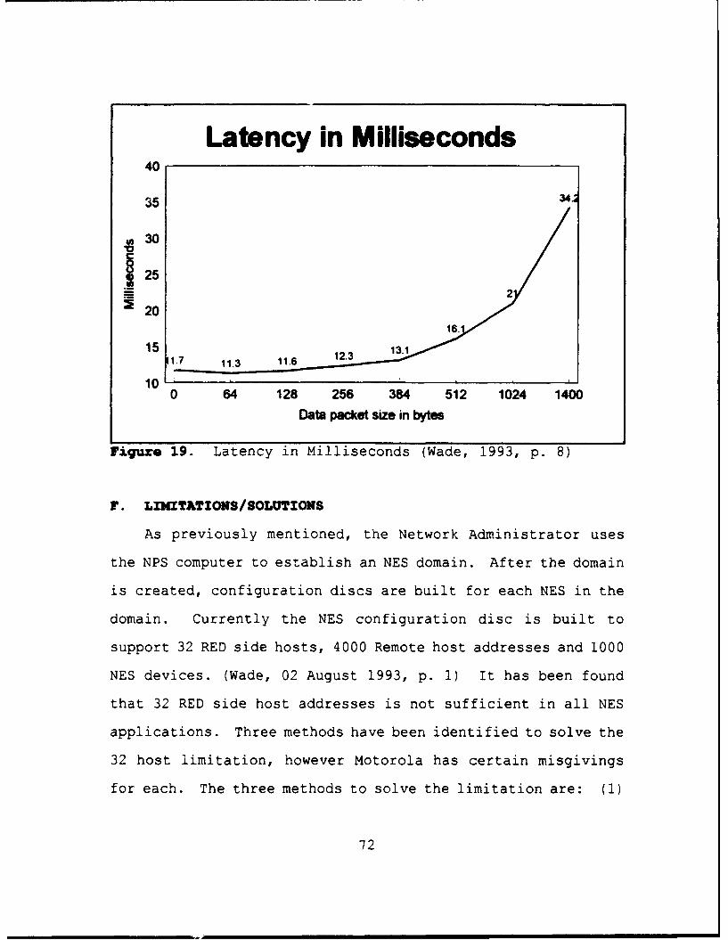
Latency in Milliseconds40
35 34.
4130
"25 2S20
16.
15 1.7 11.3 11.6 12.3 1.
100 64 128 256 384 512 1024 1400
Data packet size in bytes
Figure 19. Latency in Milliseconds (Wade, 1993, p. 8)
F. LIMITATIONS/SOLUTIONS
As previously mentioned, the Network Administrator uses
the NPS computer to establish an NES domain. After the domain
is created, configuration discs are built for each NES in the
domain. Currently the NES configuration disc is built to
support 32 RED side hosts, 4000 Remote host addresses and 1000
NES devices. (Wade, 02 August 1993, p. 1) It has been found
that 32 RED side host addresses is not sufficient in all NES
applications. Three methods have been identified to solve the
32 host limitation, however Motorola has certain misgivings
for each. The three methods to solve the limitation are: (1)
72

Increase the IBAC table for local hosts to 64 addresses, (2)
Support IP bridging using RED side routers and having no
requirement for DAC checks on discrete hosts addresses, and
(3) Use address masking to provide a method of performing the
DAC checks on a range of addresses. (Wade, 02 August 1993, pp.
1-4)
1. Increasing IBAC Table to 64 Hosts
Motorola has determined that increasing the IBAC
tables from 32 to 64 hosts is a very easy problem to fix,
however they see it only as an interim step. Exactly what the
effects of supporting 64 hosts on the RED side will have on
performance is unknown.
2. IP Bridging
The use of IP routers on the RED side of the NES would
allow the RED network to be more dynamic because DAC checks
would be performed only on the local routers Ethernet address
and the distant router or host Ethernet address. The RED
network is more dynamic in that response to addition/deletion
would be done on a local level and decrease the workload of
the Network Administrator.
The drawbacks to this are that network security and
performance may suffer as a result. Since there are no DAC
checks performed on a host's network address, any host
attached to the networks serviced by the router may have
access to the security services provided by the NES. The use
73

of IP bridging and RED routers could possibly increase the
number of RED hosts, thereby significantly increasing the
traffic on the RED side and decreased performance could
result.
3. Address Masking
Address masking could provide the Network
Administrator the ability to configure the NES to perform DAC
checks on a range of addresses and/or a set of discrete
address entries (64). This application would pose no threat
to security; however, as the number of hosts increases so does
the traffic load on the RED LAN, and degraded performance
could result. All in all, degraded performance is the result
with additional traffic load for all three options.
G. APPLICATIONS OF THE NES
The NES has been successfully demonstrated its ability to
provide E3 (End-to-End Encryption) in a tactical strategic
environment (both land-based and ship-to-shore) over
terrestrial and satellite-based networks. The NES
successfully demonstrated its use in providing secure packet
encryption from shore-based LANs to ship-based LANs through
SHF gateways during the Secure Tactical Data Network-4 (STDN)
demonstration conducted in September of 1993. It also
demonstrated that the NES can provide connectivity and
security from tactical sites to fixed sites through existing
networks such as the Defense Simulation Internet (DSI), and
74

also on future networks such as AT&T's bandwidth on demand
satellite network. (DISA Volume 2, October 1993, p. 48)
Additional DoD organizations using the NES are: the Army's
Reserve Component Automation System (RCA) is in the deployment
phase across the country; the Air Force's Headquarters System
Replacement Program (HSRP) is being installed in the Pentagon
by the 7th Communications Group; and the Office Automation &
Secure Information System (OASIS) is being installed in the
Pentagon for the Office of the Secretary of Defense (OSD).
(Motorola White Paper, 1993)
B. CONCLUSIONS
In summary, the Network Encryption System appears to be
the secure network system solution for the future. Motorola
has taken its lessons learned in the secure voice
communications business and applied them to the secure data
transmission. As a result, Motorola has produced a product
with excellent flexibility, as demonstrated by the NES's Open
Architecture, and a long application expectancy.
Additionally, the lower life cycle costs of the NES due to
modernized EKMS, adaptability to recognized standards and
interservice and worldwide interoperablity make the NES a very
attractive security device in these days of increasing
operational requirements and decreasing dollars for defense.
75

CHAPTER VI. UTILIZATION OF COMMERCIAL SATELLITES
There is currently an on-going argument between
Congress, military operators/communicators, and defense
contractors as to whether the expense of a Defense Satellite
Communications System (DSCS) follow-on program is necessary,
economically feasible, and/or worth it. Supporters of the
commercial satellite (COMSAT) option feel commercial satellite
services can provide for the military's SHF needs. Military
supporters point to the need for survivability and jam-
resistance as their main argument in support of the DSCS
follow-on constellation program. The middle-ground attitude
is that commercial satellite services should be utilized for
"surge" capacity, while at the same time there is always a
need for some protected SHF capability.
Congressional direction (beginning in 1989) mandated that
the Department of Defense (DoD) conduct a study of the
Integrated SATCOM Database (ISDB) 3 and develop a
comprehensive plan, defi.ning all SATCOM requirements and
potential soluti.ons to meet the requirements. (GAO, 1993, pp.
1-5) This direction was the impetus for the Commercial
Satellite Communications Initiative (CSCI).
3 The ISDB was proceeded by the User RequirementsDatabase (URDB), which was established in the mid-1970s todocument communication frequency requirements. The name waschanged to ISDB approximately three years ago.
76

A. COMMERCIAL SATELLITE COSOCUNICATIONS INITIATIVE (CSCI)
The CSCI was a study completed in January 1994 by defense
contractors to determine COMSAT systems capabilities. The
contractors were issued requirements documented in the
Integrated SATCOM Database (ISDB) and asked to provide a
detailed analysis of their SATCOM systems abilities to fulfill
the General Purpose and Core Requirements (as defined in
Chapter I) of the DoD user. It was known at the onset of the
study that due to commercial satellite systems inability to
satisfy Hard Core Requirements (as defined in Chapter I)
MILSTAR was currently the only means available for
communications requiring that level of protection. The
findings of the CSCI were that commercial satellite systems
could satisfy all General Purpose requirements, but could only
handle Core requirements that did not require an anti-jam
(A/J) capability. (Guiar, 1994)
B. AEROSPACE/MSO STUDY
The MILSATCOM Systems Office (MSO) of DISA conducted an
additional study from August to December 1993, known as the
Aerospace/MSO Study, to determine the capability of current
and programmed DoD satellite assets to handle the General
Purpose, Core and Hard Core requirements of DoD users. The
baseline configuration of satellite systems available used for
study purposes was as follows: four MILSTAR II satellites,
77

five DSCS III-B satellites, eight UFO satellites (six with
EHF) and terminal equipment as planned for all systems. The
study was conducted on two independent scenarios set in 2003
where wartime SATCOM throughput requirements are 1061 Mbps.4
The first scenario was a peacetime environment, and the second
was that of a combined major regional conflict (CMRC) in
Southwest Asia and Korea. Additional assumptions of the study
were: UHF communications requiring protection were migrated
to EHF, and appropriate fixed-to-fixed site requirements were
candidates for unprotected/protected optical fiber paths.
(DISA MSO, 1994, pp. 2-5)
Findings of the Aerospace/MSO study were that DSCS III and
MILSTAR II can't satisfy the remaining protected requirements
as documented on the ISDB, even after migrating 50% of
candidate requirements to commercial fiber optic lines. DISA
MSO also stated that upgrades to the DSCS satellite system are
needed to increase protected service for SHF communications.
Figures 20 and 21 show a graphical representation of the
inability of the UHF, SHF and EHF systems depicted in the
study to meet user requirements. Additionally, the graphs
show the underutilization of commercial satellite systems in
both peacetime and CMRC scenarios.
4 1061 Mbps was determined to be the future throughputrequirement after off-loading 50% of current DSCS users (whoare fixed site-to-fixed site users) to terrestrial opticalfiber, and then using the ISDB as a prediction tool.
78

iNOT TO SCALEi 464
225
100 9612 0.0 31
ADIOATES FO U1FUCOMMERCA SERVIC
K REQUTES1E aS A.LOCATED
Figure 20. Peacetime Requirement Assignment (DISA MSO,1994, p. 10)
REomVS ASGMENT TO SYSTEMS
571
315 jNOT TO SCALE
210
Figure 21. CD'RC Requirements Assignment (DISA MSQ, 1994, p.11)
79

C. INTEGRATED SATCW( DATABASE (ISDB) PROBLEMS
Using the ISDB as a frequency allocation prediction tool
to help build communication systems of the future is causing
problems. This problem is substantiated by the comments of
Mr. Bill Harding, Director of Space and Nuclear C3 , at the
March 1994 MILSATCOM Users' Conference. Mr. Harding stated
... the ISDB process is not working the way it should be.Users put in for requirements on what they think can bemet vice what they need. Thus, people in D.C. are basingstudies on faulty information in the ISDB. Users need torealize this and put in for what they actually requirevice what they think they can get. (McCollum, 1994, p. 3)
Additional problems with the ISDB are documented in an
excerpt from an interview with Mr. Bill Clair, Senior Project
Engineer, DISA MSO Communications Architecture Directorate. 5
... the problems with the ISDB are due to the fact that it(the ISDB) is being utilized in an extended application(i.e., other than it was initially designed for asdescribed in MOP 37). Using the ISDB as a requirementsprediction tool is like trying to predict the capabilitiesyou want your personal computer (PC) to have 10 years fromnow. For instance, you give the designer of your computersystem the following "grey" requirements for your systemthat you want to have designed and be fully functional forthe next 20 years: data fusion, multi-media, virtualreality, etc... The applications that the ISDB is beingused for today is like saying 10 years from now you wantto operate a communications system with a specificfrequency, a specific crypto, a specific keying mechanism,etc... The requirements specified in the ISDB are toonarrow to apply to tomorrow's systems...it has noapplicability. Trying to apply the ISDB as a bandwidthallocation prediction tool is very similar to the PCexample, and keep in mind that PCs have only been aroundfor about 13 years. But on the other hand, the ISDB isreally the only requirement prediction tool we currently
5 Bill Clair, Commander USN (retired), served as Headof Navy Satellite Communications Branch (N631), Navy SpaceSystems Division, prior to holding his current position.
80

have, so we use it, and the way we are using it now isnot working. (Clair, 5 April 1994)
Due to problem areas like these, MOP 37 will undergo a
major revision beginning in June 1994. The goals of revising
the current Military Satellite Communicatiors Systems document
will be to readdress and more strictly define areas that have
caused confusion and problems. The revision was also directed
by the DoD Inspector General U.S. Space Command Inspection
Report which made the following recommendation.
... the Chairman of the Joint Chiefs of Staff, incoordination with the Defense Space Council, revise MOP37, "MILSATCOM Systems," and MJCS-11-88, "MILSATCOMCommand and Control Operations Concept," to furtherclarify responsibilities for MILSATCOM systems between theU.S. Space Command, the Defense Information SystemsAgency, and the the Military Services. (DoD IG Report,October 1993, p. 21)
D. COIGIERCIAL SATELLITE USAGE DURING THE GULF WAR
Commercial satellites provided valuable complementary
capacity to the MILSATCOM systems being used during Desert
Shield/Desert Storm. 6 The primary commercial satellite
systems used by the United States during the Gulf War were
International Maritime Satellite Organization (INMARSAT) and
International Telecommunications Satellite Consortium
(INTELSAT) satellites. INTELSAT provided about half of the
out-of-theater SHF capacity and some 20% of the total SHF
6 Military Satellites utilized during DesertShield/Desert Storm included DSCS II, DSCS III, LEASAT,FLTSAT, GAPFILLER, TACSAT, and the United Kingdom's SKYNET.
81
capacity. INMARSAT supported major naval task forces,
sealift, and some ground unit commanders. In particular, it
supported extensive unclassified and some classified traffic
(secured with STU-III) for the Military Sealift Command and
provided connectivity to allied Navy and merchant ships. Due
to the short supply of TACSAT capacity, INMARSAT also
supported sealift and battle group commanders. (Wentz, 1992,
p. 13)
During the height of the air and ground war (January-March
1991) INMARSAT reported a 50k growth in Gulf traffic, a period
when commercial shipping would have been expected to give the
area a wide berth. INTELSAT also reported substantial traffic
increases during the Gulf War, although the bulk of this
growth was attributed to television traffic when Cable News
Network (CNN) took to the space waves and became a worldwide
household name. (Anson and Cummings, 1992, pp. 125-126)
1. Legal Issues Associated with Use of INKARSAT
Article 3(3) of the INMARSAT Convention states that
the INMARSAT Organization "shall act exclusively for peaceful
purposes." (INMARSAT, p. 1) The interpretation of "peaceful
purposes" created problems with regard to how U.S. forces were
going to use INMARSAT during the Gulf War. The Judge Advocate
General (JAG) for the CNO stated that "peaceful purposes" does
not exclude military activities so long as those activities
are consistent with the United Nations charter.
82
It is under this interpretation that INMARSAT has long
approved the installation of Ship Earth Stations (SESs) aboard
warships. (JAG, 1991, p. 1) The application of such SESs
under armed conflict created further questions, as the United
Kingdom and Iraq used SESs in the Falklands and Iran-Iraq
wars, respectively. In a December 1987 legal opinion and
March 1988 policy directive, the INMARSAT Legal Advisor stated
that in instances of armed conflict, "the SES shall only be
used for distress and safety communications or other purposes
recognized by international humanitarian law." (JAG, 1991, p.
1) These statements did not take into account the effect of
United Nations Security Council (UNSC) Resolutions.
In 1990, UNSC Resolution 678 authorized states to use
"all necessary means" to uphold and implement all previous
UNSC resolutions on the subject and "to restore international
peace and security in the area." Through this resolution, the
JAG determined that Navy units may use INMARSAT in support of
armed conflict consistent with UNSC resolutions. (JAG, 1991,
p. 1) This statement still left some question as to whether
the actions of individual Naval units were actually operating
within the bounds of UNSC resolutions. To finally eliminate
any question as to how INMARSAT could be used by U.S. forces
operating in the Pacific Region, USCINCPAC issued an INMARSAT
Policy. This policy stated that INMARSAT may be used in
peacetime for military exercises and routine operations, and
during armed conflict use is permissible for distress, safety
83
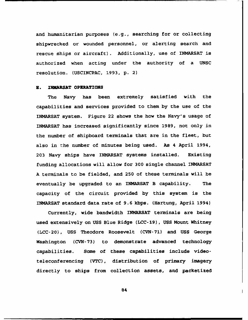
and humanitarian purposes (e.g., searching for or collecting
shipwrecked or wounded personnel, or alerting search and
rescue ships or aircraft). Additionally, use of INMARSAT is
authorized when acting under the authority of a UNSC
resolution. (USCINCPAC, 1993, p. 2)
E. INMARSAT OPERATIONS
The Navy has been extremely satisfied with the
capabilities and services provided to them by the use of the
INMARSAT system. Figure 22 shows the how the Navy's usage of
INMARSAT has increased significantly since 1989, not only in
the number of shipboard terminals that are in the fleet, but
also in the number of minutes being used. As 4 April 1994,
203 Navy ships have INMARSAT systems installed. Existing
funding allocations will allow for 300 single channel INMARSAT
A terminals to be fielded, and 250 of these terminals will be
eventually be upgraded to an INMARSAT B capability. The
capacity of the circuit provided by this system is the
INMARSAT standard data rate of 9.6 kbps. (Hartung, April 1994)
Currently, wide bandwidth INMARSAT terminals are being
used extensively on USS Blue Ridge (LCC-19), USS Mount Whitney
(LCC-20), USS Theodore Roosevelt (CVN-71) and USS George
Washington (CVN-73) to demonstrate advanced technology
capabilities. Some of these capabilities include video-
teleconferencing (VTC), distribution of primary imagery
directly to ships from collection assets, and packetized
84

":ransfer zr large Jatabase information. ,Ricketts, p94;
HartunC, "A94.
200 1200
180 182 1059
160 1000 /140 / 800
120 4 31
100 600
8060/ 400
40 47 200294
20 1 200
0 0189 90 91 92 93 89 90 91 92 93
NAVY SHIPBOARD THOUSANDS OF MINUTESINMARSAT TERMINALS OF INMARSAT SERVICE
Figure 22. Navy Use of INMARSAT (Hartung, 1994)
1.. ILR• T A/B
The INMARSAT A terminal utilizes an analog system.
Due to advancements in commercial communications technology,
:NMARSAT A is scheduled to be phased out be and replaced with
INMARSAT B, which is digital, beginning in 1996. The last
shins that will have :NMARSAT A installed onboard are the
Arleigh Burke (DDG-51) class destroyers. The reason the
NJavy's newest ships are having a soon to be retired system
installed onboard is that a class B NINMARSAT terminal has not
95

yet been appro': - by the INMARSAT council as a standard
terminal, so it not currently available for installation.
Once those terminals are available, they will begin to be
installed. Due to the rapid decommissioning of numerous
ships, the total number of INMARSAT "B" ships that will be in
service between 1996 and 2000 is 250, which is less than the
original fielding mark of 3nn ships. (Hartung, 1994)
As previously meL -.ntt. the majority of INMARSAT A
installations provide only : ringle channel capability,
therefore regardless of how efficiLat a ship is utilizing a
single channel terminal, only one teltphine call can be made
at a time. Due to the need of more telephones, multi-channel
INMARSAT A units are being installed on CV/CVN&, large
amphibious ships and Fleet Flagships. These platforms will be
provided with four circuits instead of just one. Of the four
INMARSAT lines the multi-channel arrangement provides, two
will be the high data rate (64 kbps) and two will be standard
data rate (9.6 kbps). Upgrades to single channel users
INMARSAT A systems would allow for high data rate
communications at 56 kbps. (Hartung, 1994)
2. I3MARSAT X
As INMARSAT usage has grown, two questions have arisen
from the users: (1) How can current traffic charges be
reduced? (2) How can more telephone circuits be added to the
ship? Costs will be discussed in subsequent sections. The
86

development of a new INMARSAT M system was the direct result
of the second question. The INMARSAT M system will provide
four INMARSAT M lines (4.8 Kbps per phone), which would plug
into what is normally (or previously) one high data rate line.
The end result is a net gain of 3 telephones. This capability
is scheduled to be demonstrated on USS Theodore Roosevelt in
June 1994. (Hartung, 1994) A variation of the INMARSAT M
system will be installed on Mine Counter Measure Ships and
Patrol Craft to provide them some means of utilizing INMARSAT
communications. (OPNAV, 1994, p. 5)
3. INTELSAT
Simultaneous efforts are being conducted with INTELSAT
systems to provide advanced alternate means of communication
and intelligence to the afloat commander. The current data
rate transmission capability of 150 kbps is not fast enough
for imagery to be transmitted to ships. Not only does the
information tie up the conmunications net, as it would take
between 3 and 5 hours to transmit, but it is important to get
the information there quickly, as it is time critical. As a
result of this, global beams on INTELSAT are currently being
used concurrent with exercise Challenge Athena, where a T-1
telephone line was run into USS George Washington and a "half
T-l" was run out of the ship. This increased data rate into
the ship provided imagery in minutes vice hours. The reason
for the higher data rate into the ship was to support the
87

"warrior pull" concept, where the afloat commander has the
option of drawing information he wants from a large selection
being provided on the circuit. The "half T-l" out of the
ships would allow for an additional 20 phones to be run off
the ship. These telephone lines would be capable of
supporting Secret and General Service VTC, telemedicine and
public affairs photographs. Challenge Athena is an exercise
that has received $3.5 million from Congress to explore the
INMARSAT/INTELSAT usage requirements and utilization of an
aircraft carrier as it prepares for (going through the "work-
up" process) deployment, and when it is actually deployed for
a six month period. A similar study is being conducted on USS
Mount Whitney to determine the "user-pull" requirements of an
afloat Joint Task Force Commander (CJTF). (Hartung, 1994)
F. INMARSAT COSTS
The Navy is paying INMARSAT $146,000.00 per month to lease
a 36 MHz transponder 24 hours a day to provide service to
ships that is just like picking up a commercial telephone.
The charge for using INMARSAT is based completely upon call
duration. Whenever a ship places a call and the dialed number
"answers" the call, the clock is started. Whenever the
"talkers" hang up, the clock stops. Each individual ship only
pays for the amount of service they use. The payment for
usage is made from each ship's operating target (OPTAR) funds.
If a ship never places a call, no usage fee is charged for
88

system utilization. The Navy currently pays $6.25 per minute
for the service, which is prorated into 10 second increments,
with a 30 second minimum. The normal tariff rate for usage of
INMARSAT is $10.00 per minute, but due to a Volume Subscriber
Plan (VSP), DoD only pays $6.25 for a 9.6 kbps line. The
commercial tariff charge for the upgraded 56 kbps line is
$18.00 per minute; whether the Navy will receive a high volume
discount rate has yet to be determined. (SPAWAR, 1994, p. 3;
Ricketts, 1994)
For shore originated calls, the shore originator is
charged for the call at a rate determined by the shore user's
local telephone service provider, and this charge appears on
the originator's telephone bill. As far as the local
telephone company is concerned this is simply a long distance
phone call made to one of four area codes. These area codes
correspond to the four ocean regions as defined by the
INMARSAT network: Atlantic East, Atlantic West, Indian and
Pacific. Most typically, users are charged at a rate that
approximates $10 per minute. (SPAWAR, 1994, p. 3)
In addition to ship to shore and shore to ship calls,
INMARSAT provides a ship to ship service. This service works
in exactly the same manner as all other INMARSAT calls, except
the path is a double hop from ship to satellite to earth
station and from earth station to satellite to ship. Due to
this, the call is charged as two calls at $6.25, or $12.50 per
minute. (SPAWAR, 1994, p. 3)
89

1. Additional Costs for INMARSAT A
An INMARSAT A terminal costs approximately $25,000 to
procure and $16,000 to install, except overseas where there is
an additional $ 6,000 to 10,000 charge from the INMARSAT host
nation. The 56 Kbps upgrade costs an additional $19,000 for
the hardware and $2,000 more to install. (Ricketts, 1994)
The single channel INMARSAT capability utilizes a 1.2 meter
satellite antenna.
2. Additional Costs for INWARSAT B
Anticipated costs for the INMARSAT B terminal range
between $30,000 and $35,000. This terminal is expected to be
ready for installation around 1995-96. Installation costs
should range between $6,000 and $8,000. The implementation of
the INMARSAT B package should be a change conducted in a
shipyard availability since INMAkSAT A terminal parts are
completely removed and replaced by those for the digital
variant.
3. Multi-Channel Terminal Costs
The costs of expanding a ship's capability in the four
channel arena, including the 56 kbps upgrade, is estimated to
be $315,000. The four channel terminal utilizes a 2.4 meter
satellite dish and 56 kbps satellite modem. (SPAWAR, 1994, pp.
4-10)
90

4. CO•MAT Proposals
The United States representative in the INMARSAT
organization is the COMSAT Corporation. COMSAT has suggested
leasing out-of-band channels to the Navy at a bulk rate. The
tariff rate for usage of these channels is to be determined.
Ships would get these channels on a first come, first served
basis. However, if the ship can't operate on this out-of-band
channel due to system configuration or geographical location,
they can always revert to the in-band channels to make calls
at the regular rate. COMSAT currently has a monthly 56 kbps
lease program available that would permit the Navy to lease a
56 kbps circuit, available on demand, for a flat fee of
$45,000 per month. The drawback with this is that the ships
utilizing this service have to be high volume users in order
for it to be economically feasible. INMARSAT has recently
approved several new versions of this 56 kbps service, based
primarily on Navy interest, but COMSAT has not published new
tariffs based on these developments. It is anticipated that
the new tariffs will offer shorter term versions of the
current monthly package. (SPAWAR, 1994, p. 11)
G. DSCS COST COEPARISON
The average life cycle cost of one DSCS III satellite is
$140 million. (Drozd, 1994) This figure was determined by
adding up all of the programmatic, research and development,
production, and operation and maintenance costs for the 14
91

DSCS III satellites and associated IABS and BFN modifications
and then dividing by 14. An additional $55 million must be
included for the average cost for the Atlas II Centaur rocket
used as the launch platform. (Drozd, 1994) These two costs
are then added together and divided by 10, the expected life
of the satellite. An additional $5 million dollars is paid to
Martin Marietta annually for engineering support, anomaly
resolution and system trend analysis. (Drozd, 1994)
Therefore, the total annual operational cost of one DSCS III
satellite, excluding ground station or user terminal costs, is
$24.5 million in FY 93 dollars. No time phased costs were
available, therefore discounting was not taken into account.
Table II contains the figures used to arrive at the $24.5
million estimate. (Drodz, 1994)
It must be remembered that this cost is for DSCS usage by
all DoD organizations. Figure 8 (previously presented in
Chapter IV) demonstrates how DSCS was utilized by various DoD
organizations during Desert Shield/Desert Storm, but it does
not show usage by each individual service. Figures for
individual service usage of DSCS were not available to the
author due to administrative problems and the classification
of this thesis. It is difficult to determine percentage of
use by service due to issues concerning power and capacity.
While the Navy's power allocation on DSCS III satellites is
50% of the power on Channel 1 and the maximum throughput
capacity is 512 kbits, the DSCS usage percentages by service
92

are not consistent due to the variance in transponder size.
(Baciocco, 1994) Figure 11 (previously presented in Chapter
IV) demonstrates the different power requirements of four
foot, eight foot and 38 foot dish antennas. Additionally, the
DSCS III satellites have been over-engineered, which will
cause actual operating lifetimes to extend. This in turn will
cause the average annual operational cost of a DSCS III
satellite to fall, while INM4ARSAT charges remain constant.
The Navy's used 1,059,000 minutes of INMARSAT service in
1993. (Rasmussen, 1994) The total cost for the Navy to
utilize INMARSAT in 1993, including terminals, is $10,494,750.
Table III contains the figures used to arrive at the
$10,494,750 million estimate. (Hartung, 1994) The other
services usage of INMARSAT in 1993 were as follows: Army
units - 171,448 minutes; Air Force units - 55,520 minutes;
Marine Corps - usage included in Navy figure of 1,059,000
minutes. (Rasmussen, 1994) The services were charged the
Defense Commercial Communication Office (DECCO) discount rate
of $6.25 per minute of usage. Military Sealift Command (MSC)
used INMARSAT for 360,000 minutes of voice traffic and 750,000
minutes of data transmission. Military Sealift Command units
were charged $8.00 per minute for voice traffic and $4.00 per
minute for data transmissions. (Rasmussen, 1994) The rates
MSC units were charged for INMARSAT usage are different from
the rates charged the military organizations of DoD due to
some participating MSC units not being included in the DECCO
93

contract with COMSAT. The total amount paid by DoD
organizations to COMSAT Mobile Communications for INMARSAT
service (excluding terminal costs) in 1993 was $13,917,300.
(Rasmussen, 1994) Navy and MSC units were responsible for
$12,498,750 of the total charge, demonstrating their
dependence on INMARSAT due to the lack of land line
connectivity during at sea operations.
No direct comparison can be made between DSCS III and
INMARSAT costs due to the fact that the costs for DSCS III are
based on a quant' *y average and INMARSAT costs are calculated
on a time basis. The quantity average is determined by
dividing the total programmatic costs for the DSCS III program
by the quantity of satellites produced. The time-based
calcution is determined by calculating the time of service
usage and multiplying by the service charge. It must also be
remembered that quality of the service provided by DSCS III
satellites and INMARSAT are not the same, as DSCS III
satellites provide some anti-jam capability but INMARSAT
provided none.
94
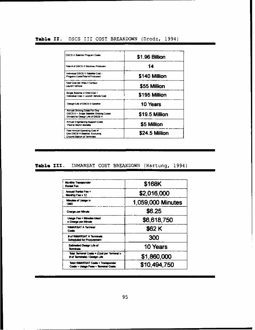
Table 11. DSCS III COST BREAKDOWN (Drodz, 1994)
DCIII Saftaie Program Coaft $1 .96 Billion
Ttal 0 Nof DSCS III Satellie Pro*,*"o 14
Pro~a =1 Prouced$140 MillionTotal Coal pe Alin It Centaur
Laurch Vhc*$55 MillionSirr0. Satwib~ mi (Ot CoalIndrv.ica Cost + Laifroft ettrle Cost $195 Million
006 Lie f OCSIIISaellte10 YearsAnnual Orbtrng Cook For Om
Divclem=by e~amsig Lt o SC 1 $19.5 MillionAu Engmrdwring Su~pport CosfM llo
Paid to AMatn malmala $5Milo
OneDSC II SaleI, Ecluing$24.5 MillionIGround Station of Temonals ______________
Table 111. INMARSAT COST BREAKDOWN (Hartunig, 1994)
________Fee_ $168KAtvmfa Rufta FeeMoriftlFee It 2 $2,016,000
I= 1,059,000 Minutes
Ch@W W Wift $6.25It_______per______ $6,618,750INMARSAT A Teffmmi$2
0 of OtMARSAT A lbi~mmam 0Sddu~ied for PrOPArAmmW 300_______
TOnuM*" ggL~ 10 YearsTOwA Tomtim CW*Comb pe Teevmui It#.F=wW)Ds"cnub~ $1,860,000
Cot* @ ews* TftmpafldmU $10,494,750
95

H. REPRESENTATIVE FLEET USAGE OF INMARSAT
INMARSAT terminals are primarily used for mission support
(i.e., non-tactical) whether it be to maintain crew morale,
obtain current logistics support information, or to aid in the
completion of operational planning. The breakdown of one
aircraft carrier's calls over a three month deployed period
showed that 15W of the calls were for unclassified information
related to the Streamlined Automated Logistics Transmission
System (SALTS, defined in Appendix B); 25% of the calls were
made by the crew by means of prepaid calling card calls; and
the remaining 60t were for daily operations of the ship (e.g.,
STU-III, direct dial, etc...). [Ricketts, 1994]
The average SALTS call completed during this three month
survey was 2.8 minutes. Analysis of the costs associated with
SALTS calls shows that 60% of the total cost comes from only
18% of the calls, suggesting these were extremely long calls.
The throughput speed of data transmission experienced was in
the range of 2.4 to 9.6 kbps. If the "long" SALTS calls had
been completed on a 56 kbps circuit rather than a 9.6 kbps
single channel circuit, the call transmission time could have
been cut dramatically. For example, a 12.8 minute call on a
9.6 kbps line corresponds to a 2.5 minute call on a 56 kbps
line. For simplification of the model comparison, the
"average" 56 kbps call session would require 3 minutes. Using
the $6.25 per minute fee for 9.6 kbps and $11.90 per minute
for 56 kbps, the average savings per SALTS session by using a
96

56 kbps circuit is $45 per session. The standard operating
procedure for the carrier was to conduct two SALTS sessions
per day, therefore the saving would be $90 per day. (SPAWAR,
1994, p. 12)
Recalling that the cost incurred by the Navy to upgrade a
ship's INMARSAT system to a 56 kbps capability is
approximately $22,000, it would take 233.33 days to recoup the
investment for the upgrade. Two hundred and thirty-three days
is approximately 1.2 deployments. It appears that the
potential savings provided by the 56 kbps circuit is an
excellent way to reduce traffic charges and more efficiently
use the INMARSAT system.
97

VII. CONCLUSIONS AND RECNK M'DATIONS
The Navy's SHF SATCOM program, like all military programs,
is experiencing the far reaching effects of the fall of the
Soviet Union. The re-evaluation of our National Military
Strategy, and our strategic shift from global and theater
warfare to crisis operations and low intensity conflicts has
altered the emphasis of the factors driving development of
future MILSATCOM systems. Before Desert Shield/Desert Storm
and before the end of the "Cold War" the factors driving
advancement of MILSATCOM systems in order of emphasis were:
responsiveness, coverage, protection, capacity and cost. The
demise of the once powerful "Soviet Bear" has caused the
emphasis on these factors to become: cost, capacity,
coverage, responsiveness and protection.
Congress wants the MILSATCOM architecture to include as
many commercial systems as much as possible, referring to how
successfully they were employed during Desert Shield/Desert
Storm. Additionally, political pressure seems to be steering
future development of MILSATCOM systems in the direction of
cheaper, more capable, less protected systems.
This is a dangerous trend; recovering from such practices,
if established, could be much more costly than if the proper
systems were developed and implemented. Former ideas of
fighting a European land battle and taking advantage of
98

existing telecommunications networks and systems in NATO
countries no longer are valid. It must be remembered that
Iraq did not jam U.S. and coalition satellite communications;
and even if they did, the location conducting the jamming
could have been targeted and eliminated. Crisis operations,
low intensity conflicts, and humanitarian operations are more
likely to occur in "third world" countries whei
telecommunications systems capable of supporting the C41
requirements of our commanders do not exist. This is what
should be remembered while decisions are being made regarding
future MILSATCOM systems.
The revision of MOP 37, scheduled to begin in June 1994,
will attempt to more closely define the applications of the
ISDB and determine a way to make the ISDB more of an accurate
reflection of what DoD's frequency requirements really are.
If this can not be done, then research dollars should be spent
on ways to design something new which could more realistically
be used as a bandwidth allocation prediction tool. The
pressure calling for increased utilization of commercial
satellite assets may affect the revision of MOP 37. Areas of
the document that could potentially be influenced by political
pressure are the definitions for general purpose, core and
hard core requirements. Restructuring of these definitions
could make commercial SATCOM systems more applicable in the
MILSATCOM architecture.
99

It appears that the DSCS requirements screening process is
beginning to shift fixed-site-to-fixed-site users to
tc.:restrial optical fiber lines instead of DSCS satellites,
based on the study completed by MSO/Aerospace. Not only would
this free up channels on DSCS, but the fixed-site users would
no longer face power limitations and would gain bandwidth as
a result.
The first recommendation is to significantly increase
training efforts in the area of SHF SATCOM. The Navy made
great advances in command and control under the leadership of
Vice Admiral Tuttle. He really "got the ball rolling" as far
as development of advanced communications systems goes. The
Chief of Naval Operations Space and Electronic Warfare
Directorate (N-6) produced a document entitled Sonata in 1992,
which stated:
... DoD no longer is driving research and development. In1962, the U.S. Navy was responsible for over 50 percent ofthe nation's research and development expenditures onelectronics. Thirty years later, Navy is less than fivepercent. (CNO SEW, 1992, p. 48)
Since the Navy is no longer the leader in production,
design, sales, and distribution of electronics, we have to
focus our efforts on training. Ground and maritime forces,
carrier battle groups, amphibious readiness groups, and Fleet
Flagships are experiencing problems while "in-chopping" from
one CINC area of responsibility (AOR) to another. Comments
from CINCCENT cite lack of training, documentation,
standardization of hardware and software for these problems.
100
(Baciocco, 1994) The Chief of Naval Technical Training has
also received a requirement for SHF SATCOM training and has
requested implementation of various degrees of training
programs for potential SHF SATCOM users. These users range
from division officers and department heads to surface
communications systems operators. (CNO, 01 April 1994, p. 1)
New systems fielded without sufficient documentation and
user training are a major problem. As a case in point,
QUICKSAT was initially only supposed to be an interim program
to support five ships, but now there are 13 ships with
QUICKSAT. The thought process for meeting training
requirements was through on the job training (OJT). (Martin,
1994) Training methods began to improve slightly when the
installing activity trained up the ships crews on how to
operate the new equipment. It was initially thought that this
technique would work, but within about two years everyone who
had been trained by the installers had rotated. An additional
two years later the operational effectiveness of the systems
operators was significantly decreased from what it should have
been. The ships' capabilities were deficient due to a loss of
"corporate knowledge" on how to operate the equipment.
Further problems were encountered as the communications
equipment began to be cross decked from returning ship to
deploying ship due to a lack of equipment.
101

NAVELEX Portsmouth (now called NISE East) is putting
together a three volume training handbook as a baseline to
help begin bridging the training gap. Volume one of the
handbook is an executive summary, aimed for use by commanding
officers. The second set of volumes (a multi-volume set) is
a by-component description of all the items currently in the
Navy's SHF inventory. The third volume is a ship-specific
systems diagram book, which can be used by the operators itz
training purposes or to help troubleshoot problems while on
deployment. NISE East has also put together a five week users
course for more hands-on training. Current training schedules
from NISE East anticipate providing eight more courses per
year. This may paint an optimistic picture for SHF SATCOM
training programs, but Fleet Flagships with pre-QUICKSAT
(Phase 0) using the OM-55 modem will soon have no training
support, as the operator/maintainer course in Norfolk has been
cancelled. (Martin, 1994)
Future training programs need to be developed so the
sailor going through the "A school" training pipeline learns
all the theory, fundamentals, and actually gets to operate a
prototype system; this should be similar to the way the Navy
trains nuclear pipeline training. This way, when the sailor
goes to the ship, he/she can adapt to the actual onboard
system and can bridge that gap by using onboard training aids
like the volume three handbook provided by NISE East. Another
established training method which the Navy's nuclear program
102

has proven effective is utilization of two to three week
schools for crews after deployments, emphasizing problems
experienced during the deployment. Establishmen. of a
remedial course in Norfolk and San Diego to sharpen fleet
operator skills 10 to 12 months after they have reported to
their ship could also complete this requirement. The bottom
line is that the sailor needs to be trained for a Navy
enlisted code (NEC) as a SHF SATCOM operator instead of a WSC-
6 technician. The program needs to train for an open
architecture vice a systems architecture. This idea could
also adapt to a joint environment by training operators as
SATCOM technicians and have them become familiar with more
than one SATCOM system. Efforts are currently being made to
move the Navy's SATCOM pipeline training to Fort Gordon to
co-locate with the Army's DSCS training center. The Navy
personnel would attend separate specific courses from the Army
personnel, but they would be able to take advantage of the
Army's operating facilities and be exposed to the Army's
training. (Martin, 1994)
Additional emphasis must be placed on the responsibility
of the newly formed Afloat Training Group (ATG) to train the
fleet operators. The ATG also needs to develop training plans
and methods to better support the combat systems and
communications training programs. But once again the problem
with getting these types of programs started is money.
Funding for development of the curriculum isn't necessarily
103

the problem; the problem is getting the billets for the
instructors, because it involves permanent change of station
(PCS) orders.
The final recommendation is to develop the future SATCOM
architecture as a mix of MILSATCOM systems and commercial
systems. The reason both systems are necessary is quite
simple, protection and savings. Commercial systems can't
provide the antijam capability required for specific core and
hard core communications, and MILSATCOM systems are too
expensive to operate as the sole system. This "middle ground"
attitude emerging within the SHF SATCOM community seems to
indicate that commercial satellite services will be used for
"surge" capacity. The only problem with this idea is defining
what "surge" means. What kinks of communications requirements
constitute surge? Video teleconferencing? Tomahawk mission
data updates (MDUs)? Closer inspection of increased message
traffic during Desert Shield/Desert Storm showed that much of
the "surge" was nothing more than multiple copies of the same
message being sent. Definitions of "surge" must be provided,
because communications that are required once daily in
condition three operations may become four and five times
daily in condition one or two operations. Also,
communications that fall into the "surge" category must be
strictly defined; otherwise these communications that "require
a miracle" to establish will become daily routine to the
commander who becomes accustomed to operating with it.
104

Commercial SHF SATCOM systems should continue to be used for
development of future capabilities, as they are now in the
Secure Tactical Data Network demonstrations and Ulchi Focus
Lens exercises. Great pains need to be taken, though, to
eliminate C-band interference and self-jamming problems, as
this is what caused HMS Sheffield to be sunk by an Argentine
launched Etendard/Exocet missile during the Falklands War in
May 1982. The British SHF satellite communications system
(SCOT) blocked out detection of the Etendard/Exocet radar and
caused the subsequent loss of 20 British sailors and a Type 42
guided-missile destroyer. (Woodward, 1992, pp. 1-22)
105

APPDIDIX A. ACRONYMS
ACU - Antenna Control Unit
AFCEA - Armed Forces Communications and ElectronicsAssociation
AFRTS - Armed Forces Radio Television System
ARP - Address Resolution Protocol
ARPA - Advanced Research Projects Agency
ACS - Advanced Communications Systems
AJ - Anti-Jam
ANDVT - Advanced Narrowband Digital Voice Terminal
AOR - Area of Responsibility
ASDC3 I - Assistant Secretary of Defense for Command,Control, Communications and Intelligence
ATG - Afloat Training Group
ATO - Air Tasking Order
ATS - Applications Technology Sensor
BFN - Beam Forming Network
BLACK - Secure/Encrypted
BPS - Bits per Second
BPSK - Bi-Phase Shift Keying
BSS - Broadcast Satellite Service
CCC - CINC Command Center
C4 I - Command, Control, Communications, Computersand Intelligence
C4 IFTW - Command, Control, Communications, Computersand Intelligence for the Warrior
106

C31 - Command, Control, Communications and
Intelligence
CCEP - Commercial COMSEC Endorsement Program
C2 I - Command, Control and Intelligence
CINC - Commander in Chief
CINCCENT - Command in Chief Central Command
CJCS - Chairman, Joint Chiefs of Staff
CJTF - Commander Joint Task Force
CLF - Combat Logistics Force
CMRC - Combined Major Regional Conflict
CMS - Classified Material System
CNN - Cable News Network
CNO - Chief of Naval Operations
COMSEC - Communications Security
COTS - Commercial off-the-shelf
CTAPS - Contingency Theatre Automated Planning System
CTS - Communications Technologv Satellite
CV - Conventionally Powered Aircraft Carrier
CVN - Nuclear Powered Aircraft Carrier
DAB - Defense Acquisition Board
DAC - Discretionary Access Control
DAMA - Demand Assigned Multiple Access
DATS - Despun Antenna Test Satellite
DBS - Direct Broadcast System
DDN - Defense Data Network
DECCO - Defense Commercial Communications Office
107

DISA - Defense Information Systems Agency
DISN - Defense Information Systems Network
D/L - Down Link
DLIU - Digital Line Interface Unit
DoD - Department of Defense
DSCS - Defense Satellite Communications System
DSCSOC - DSCS Operations Center
DS/DS - Desert Shield/Desert Storm
DSNet - Defense Secure Network
DSVT - Digital Subscriber Voice Terminal
DTE - Data Terminal Equipment
ECCM - Electronic Counter-Counter Measures
ECP - Engineering Change Proposal
EIRP - Effective Isotropic Radiated Power
EKMS - Electronic Key Management System
E3 - End-to-End Encryption
FAX - Facsimile
FCC - Federal Communications Commission
FDMA - Frequency Division Multiple Access
FFRDC - Federally Funded Reasearch and DevelopmentCenter
FSS - Fixed Satellite Service
FTC - Fleet Training Center
FY - Fiscal Year
Gbps - Giga bits per Second
GDA - Gimbaled Dish Antenna
108

GENSER - General Service
GGTS - Gravity Gradient Test Satellite
GMF - Ground Mobile Forces
G/T - Gain-to-Temperature
HAC - House Appropriations Committee
HDR - High Data Rate
HEMP - High-Altitude Electromagnetic Pulse
HF - High Frequency
HMS - Her Majesty's Ship
HPA - High Power Amplifier
HSRP - Headquarters System Replacement Program
IABS - Integrated Apogee Boost Subsystem
IBAC - Identity Based Access Control
IDCSP - Initial Defense Communications SatelliteProgram
INMARSAT - International Maritime Satellite Organization
INTELSAT - International Telecommunications SatelliteConsortium
INTMILSAT - International Military Satellite
I/O - Input/Output
IP - Internet Protocol
ISDB - Integrated SATCOM Database
ISO/IEC - International Organization for Standardizationand the International ElectrotechnicalCommittee
ITU - Internatinal Telecommunications Union
ITW/AA - Integrated Tactical Warning and AttackAssessment
109
JAG - Judge Advocate General
JCSC - Joint Communications Satellite Center
JFACC - Joint Force Air Component Commander
JMCIS - Joint Maritime Command Information System
JMPA - Joint MILSATCOM Panel Administrator
JOTS - Jpoint Operational Tactical System
JRSC - Jam Resistent Secure Communications
K - Kelvin
KBPS - Kbits per Second
KSD-64A - Encryption key for NES
LAN - Local Area Network
LANTDIS - Atlantic Deployable Intelligence System
LDR - Low Data Rate
LEASAT - Leased Satellite
LHA - Amphibious Assault Ship
LHD - Multi-purpose Amphibious Assault Ship
LOCC - Local Operation Control Center
LPD - Low Probability of Detection
LPH - Landing Platform Helicopter Dock
LPI - Low Probability of Intercept
LSTDM - Low Speed Time Division Multi-plexer
MAC - Mandatory Access Control
MARISAT - Maritime Satellite
MBA - Multi-Beam Antenna
MCEB - Military Communication Electronics Board
MDU - Mission Data Update
110

MMBA - Multi-Beam Multi-Mission Broadband Antenna
MMD - Mean Mission Duration
MOP - Memorandum of Policy
MPA - Medium Power Amplifier
MSC - Military Sealift Command
MSO - MILSATCOM Systems Office
MTBF - Mean Time Between Failures
MTTR - Mean Time To Repair
NASA - National Aeronautics and Space Administration
NATO - North Atlantic Treaty Organization
NAVFOR - Naval Force Commander
NCA - National Command Authority
NCCOSC - Naval Command, Control and Ocean SurveillanceCenter
NCT - Network Control Terminal
NCTAMS - Naval Computer and Telecommunications AreaMaster Station
NEC - Navy Enlisted Code
NES - Network Encryption System
NOSC - Naval Ocean System Command
NPS - NES Product Server
NSA - National Security Agency
NSNF - Nonstrategic Nuclear Forces
NT - Network Terminal
NTCS-A - Navy Tactical Command Control System Afloat
OASIS - Office Automation & Secure Information System
OJT - On the Job Training
iii

OPTAR - Operating Target
OSD - Office of the Secretary of Defense
OSS - Operations Support System
PAUC - Program Acquisition Unit Costs
PC - Personal Computer
PCS - Permanent Change of Station
PN - Pseudo-Noise
POM - Program Objective Memorandum
POTS - Plain Old Telephone System
P31 - Pre-Planned Product Improvement
RCAS - Reserve Component Automation System
RED - Clear/Unencrypted
RFI - Radio Frequency Interference
SALTS - Streamlined Automated Logistics TransmissionSystem
SATCOM - Satellite Communications
SCI - Sensitive Compartmented Information
SCSC - System Common Signaling Channel
SCT - Single Channel Transponder
SDNS - Secure Data Network Systems
SEU - Servo Electronics Unit
SHF - Super High Frequency
SIOP - Single Integrated Operating Plan
SNCC - SATCOM Network Control Center
SRWI - SATCOM Radio Wireline Interface
STC - Satellite Television Corporation
112

STDN - Secure Tactical Data Network
STel - Stanford Telecommunications
STEP - Standard Tactical Entry Point
STU-III - Secure Telephone Unit Third Generation
SPAWAR - Space and Naval Warfare Systems Command
SURTASS - Surveillance Towed Array Sensor System
TDA - Tactical Decision Aids
TDA - Tunnel Diode Amplifier
TEK - Traffic Encryption Key
TESS - Tactical Environmental Support System
TRIB - Transfer Rate of Information Bits
TWT - Traveling Wave Tube
UFO - UHF Follow-On
UHF - Ultra High Frequency
U.K. - United Kingdom
UNSC - United Nations Security Council
URDB - User Requirements Database
USAF - United States Air Force
USMTF - United States Message Text Format
VIXS - Video Information Exchange System
VLSI - Very Large Scale Integrated (Circuits)
VME Board - Versa Module Eurocard Back Plane
VSP - Volume Subscriber Plan
VTC - Video-Teleconferencing
WAN - Wide Area Network
WWMCCS - Worldwide Military Command and Control System
113

APPENDIX B. HOST SYSTZ. DZSCRIPTION
The following descriptions of host systems utilized on SHF
SATCOM were taken from the document SHF SATCOM BATTLE FORCE:
EXECUTIVE OVERVIEW, produced by the Naval Command, Control and
Ocean Surveillance Center. (NCCOSC, 1994, pp. 4-3)
TAPS Contingency Tactical Air Control System (TACS)
Automated Planning System. Joint system (developed by USAF)
used to provide planning and mission monitoring assistance and
specifically for construction and review of the Air Tasking
Order (ATO). The Navy is integrating the ATO functionality of
CTAPS into Joint Maritime Command Information System (JMCIS).
DSNet - Defense Secure Network. Comprised of three distinct
networks in the Defense Data Network (DDN). DSNet 3 is a
Sensitive Compartmented Information (SCI) Top Secret network
supporting the Department of Defense (DoD) Intelligence
Information System (DODIIS) which is accessed by Joint Defense
Intelligence Support Services (JDISS). DSNet 2 is a GENSER
Top Secret network supporting the WWMCCS Intercomputer Network
(WIN). DSNet 1 is a GENSER Secret network serving other
service and agency users. Typical remote terminal access data
rate: 9.6 kbps.
114

TACTrMIAND% - Tactical Terminal/Advanced Narrowband DigitalVoice Terminal. Military operator-assisted, encrypted, anddial-up voice interface between ANDVT and STU-III users via aSATCOM Radio Wireline Interface (SRWI) located at each NavalComputer and Telecommunications Area Master Station (NCTAMS).Typical remote terminal access data rate: 2.4 kbps.
JDXSS - Joint Defense Intelligence Support Services.Descendant from the Atlantic Deployable Intelligence System(LANTDIS) which provides afloat subscribers access to selectedportions of the DODIIS through a consolidated theaterintelligence center ashore. Typical remote terminal accessdata rate: 2.4 - 56 kbps.
1 - Joint Maritime Command Information System. The NavyTactical Command and Control System - Afloat (NTCS-A) [whichevolved from the Joint Operational Tactical System (JOTS)] andthe Operations Support System (OSS) have merged to become theJoint Maritime Command Information System (JMCIS). JMCIS isthe primary afloat C21 tactical information management systemwith user selectable tactical decision aids (TDA) to processand display data from national, regional, and organicsensors/sources on friendly, hostile, and neutral forces.Typical remote terminal access data rate: 9.6 kbps.
JWICS - Joint Worldwide Intelligence Communications System.Eventual replacement for the DODIIS and will become the SCIcomponent of the Defense Information System Network (DISN).
QOrderwir - Mandatory operator to operator circuit used forreal-time management and control of SHF SATCOM links and theirhosted circuits once a SHF link is established . Thiscomplements established United States Message Text Format(USMTF) record message format Procedures. Typical remoteterminal access data rate: 300 bps.
POT - Plain Old Telephone System. Provides direct-dialunclassified access to commercial and DSN telephone networks.Both end users must use STU-IIIs for classified calls. Callsmay be placed to/from the ship. Only differs from STel/STU-III system by eliminating the STel modem. A TIMEPLEXmultiplexer is only used for voice compression when STU-IIIsare not used. POTS line data rate: 8 or 16 kbps.
SALTS Streamlined Automated Logistics Transmission System.Unclassified, automated dial-in computer bulletin board systemused to deliver and receive a variety of logistics, personnel,and maintenance data products thereby reducing traffic loadson tactical circuits and increasing delivery speed andaccuracy. The system uses telephone connectivity such as land
115

line, cellular, INMARSAT, STel, and POTS. Typical remoteterminal access data rate: 9.6 kbps.
STel/STU-111 - Stanford Telecommunications/Secure TelephoneUnit - Third Generation. Encrypted, direct-dial telephone,FAX, and PC-to-PC access using STU-IIIs employs the STelDigital Line Interface Unit (DLIU) for connection to existingshipboard analog telephone switches to accommodate multiplexeruser access. Calls can be placed to/from the ship. Typicalremote terminal access data rate: 2.4 kbps.
Tactical TTY - Provides traditional tactical teletype servicebetween group communications operators for circuitcoordination, message traffic, etc. Circuit/network datarate: 75 or 300 bps.
TESS-3 - Tactical Environmental Support System - ThirdGeneration. A modular and interactive computer-based systemwhich collects, processes, analyzes, disseminates, anddisplays oceanographic and meteorological data products. Itcan be interfaced with JMCIS via NCTS-A/NCSS IntegratedTactical Environmental System (NITES). Typical remoteterminal access data rate: 2.4 or 9.6 kbps.
TRITAC/h- 68 - Direct, secure telephone connectivity (referredto as the "Bat phonem) to the Pentagon Red Switch for use byCJCS, CINCs, and the National Command Authority (NCA). Formaldesignation of this circuit is the Digital Subscriber VoiceTeminal (DSVT). Phone line data rate: 16 kbps.
VXXS - Video Information Exchange System. Provides 24 hoursecure video teleconferencing (VTC) between and among the CNOsstaff, fleet commanders, tactical commanders at sea, andequipped shore-based commands at the GENSER Secret level.Typical remote terminal access data rate: 112 kbps.
VYD - Voice, Video, Fax, and Data Terminal. Although notdedicated to a specific network or function, the system useshigh data rate STU-IIIs and commercially available PCs tosecurely exchange large data and imagery files whilepermitting simultaneous secure telephone conversations. It isalso capable of displaying freeze-frame video or facsimile andreal-time multiple "telestrator" annotations. Remote terminalaccess data rate: 9.6 kbps.
_WNKCS - Worldwide Military Command and Control System.Provides the means for operational direction and technicaladministrative support involved in the command and control ofU.S. military forces plus worldwide status of forcesinformation and E-mail capability for joint planning andcoordination. It provides a multipath channel of secure
116

communications to transmit warning and intelligenceinformation to the NCA and the means for the NCA to directU.S. combatant commanders. Typical remote terminal accessdata rate: 2.4 - 9.6 kbps.
117

APPUDIX C. BLOCK DIAGRAMS
OUICKSAT__ PART Or- AWT&C-MI
WWMCS -UU jC-1 TKa
CTAPS- - C24EL
SHORE FCILITIE
TLE OI WETA P:AcaJT SATCOUAC GAMT TLVdAL
wwmcc - -taui ma
l i e s , 0 4 - M D -o S 1 W I
OTHER 04- L
Figure 23. QUICKSAT BLOCK DIAGRAM (SPAMAR, 1994, p. 14)
ile

PHASE 11 TERAMNAL CW]~ @061:SISSMf ft ="I 30 1WM 4
- rnAf"
VT ~I~eM I.1~ijiiLTsvsiuw N c
koco --SHORE FACILMTES
TCF SATCC
A EAWN) TEAIMYL
Un T c WP7
Dc 1p. ...
Figure 24. PHASE II BLOCK DIAGRAM (SPAWAR, 1994, p.15)
119

AN"PM~ (2 NZE OPTIOIWPEDESTAL. AND PAOM
P&Y USE 2 ANWSMM.M
.4-~~~- --ý -m m .
l E I LMti Al I PA SrDOCK POVREI
"OAMLEOIAIADAhP -- ___-I TSTTMOATA APEES
Inc¶ , cm__ _W?
I- M~G4VCOMMA-IM
vqN Gp~ 2TRUT 1111C
Figure 25. PHASE III BLOCK DIAGRAM (SPAWAR, 1994, p. 20)
120

APPENDIX D. DSCS DESIGN DETAILS AND SPECIFICKTIXOS
The information enclosed in this Appendix was obtained
from satellite design details section of the Aerospace
Corporation's Communication Satellites 1958-1992. (Martin,
1991, pp. 95-113)
A. DSCS I/IDCSP
1. Design Life
The design life of the DSCS I/IDCSP was required to be
1.5 years, with a three-year goal.
2. Orbit
The DSCS I/IDCSP orbits at an altitude range of
approximately 17,800 to 18,700 nautical miles. The
inclination is < one degree for most satellites, with
approximately 30 degrees longitudinal drift per day.
3. Shape/Dimensions
The DSCS I/IDCSP is shaped like a polyhedron, 36
inches in diameter and 32 inches in height.
4. Weight
The Gravity Gradient Test Satellite (GGTS) version of
the DSCS I/IDCSP weighed 104 pounds, while the Despun Antenna
Test Satellite (DATS) variant weighed 150 pounds.
121

5. Power Source
Solar cells, approximately 40 Watts, power the DSCS
I/IDCSP satellite. No batteries were contained on the
constellation, therefore there was no operation during
eclipse.
6. Stabilization/RP~s
The DSCS I/IDCSP was spin-stabilized at 150 rpm.
7. Configuration
The configuration of the DSCS I/IDCSP satellite was
one 20-Mhz bandwidth double-conversion repeater.
8. Capacity
The capacity of the DSCS I/IDCSP satellite was up to
five commercial quality two-way circuits, eleven tactical
quality two-way voice circuits, or 1550 teletype. Data rates
supported by the DSCS I/IDCSP were approximately 1 Mbps.
9. Transmitter
The transmitter of the DSCS I/IDCSP consisted of two
TWTs (one on, one standby) that operated in the 7266.4 to
7286.4 MHz frequency range, with three watts of output and
seven dBW ERP maximum.
10. Receiver
The receiver operated in the 7985.1 to 8005.1 MHz
frequency range, with a noise figure of 10 dB.
122

11. Antenna
The DSCS I/IDCSP operated with two biconical horn
antennae (one transmit, one receive), with 28 x 360 degree, 5
dB gain, circular polarization. The DATS variant antenna
elements were mounted on a cylinder placed along the spin axis
at one end of the satellite, which provided an additional gain
of 10 dB.
B. DSCS II
1. Design Life
The design life of the DSCS II was five years, with a
three year mean mission duration (MMD).
2. Orbit
The DSCS II birds orbit on a synchronous, equatorial
orbit. The inclination is < three degrees.
3. Shape/Dimensions
The DSCS II satellite is shaped like a cylinder, nine
feet in diameter, and six feet in height (13 feet overall).
4. Weight
The DSCS II satellite weighed 1350 pounds when
launched.
5. Power Source
Solar cells and NiCd batteries provided approximately
520 Watts of power initially to the DSCS II, and 388 Watts
minimum at the end of five years.
123
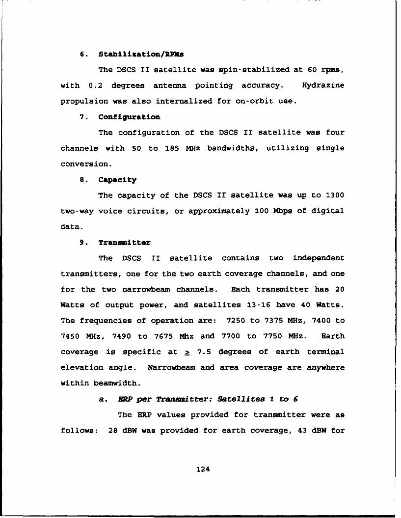
6. Stabilization/RP~s
The DSCS II satellite was spin-stabilized at 60 rpms,
with 0.2 degrees antenna pointing accuracy. Hydrazine
propulsion was also internalized for on-orbit use.
7. Configuration
The configuration of the DSCS II satellite was four
channels with 50 to 185 MHz bandwidths, utilizing single
conversion.
8. Capacity
The capacity of the DSCS II satellite was up to 1300
two-way voice circuits, or approximately 100 Mbps of digital
data.
9. Transmitter
The DSCS II satellite contains two independent
transmitters, one for the two earth coverage channels, and one
for the two narrowbeam channels. Each transmitter has 20
Watts of output power, and satellites 13-16 have 40 Watts.
The frequencies of operation are: 7250 to 7375 MHz, 7400 to
7450 MHz, 7490 to 7675 Mhz and 7700 to 7750 MHz. Earth
coverage is specific at a 7.5 degrees of earth terminal
elevation angle. Narrowbeam and area coverage are anywhere
within beamwidth.
a. RP per Transmitter: Satellites 1 to 6
The ERP values provided for transmitter were as
follows: 28 dBW was provided for earth coverage, 43 dBW for
124

one narrowbeam antenna, and 40 dBW for each of two narrowbeam
antennas.
b. ERP per Transmitter: Satellites 7 to 12
The ERP provided for transmitters were as follows:
28 dBW was provided for earth coverage, 43 dBW for the
narrowbeam antenna, 31 dBW for the area coverage antenna, and
40/28 dBW using both narrowbeam and area coverage (50% of
power to each) antennas.
c. RRPper Transmitter: Satellites 13 to 16
The ERP provided for transmitters were as follows:
31 dBW was provided for earth coverage, 46 dBW for the
narrowbeam antenna, 34 dBW for the area coverage antenna, and
40/33 dBW using both narrowbeam and area coverage (75% of
power to area coverage) antennas.
10. Receiver
The receiver operated in the 7900 to 7950 MHz, 7975 to
8100 MHz, 8125 to 8175 MHz, 8215 to 8400 MHz frequency range,
with a noise figure of 7 dB. The receiver also had tunnel
diode preamplifiers and limiter/amplifiers.
11. Antenna
The DSCS II satellites have two earth coverage horn
antennas (one to transmit and one to receive), which provide
16.8 dB gain at edge of earth; two narrowbeam parabola
antennas, 44 inches in diameter, that provide a 2.5 degree
beamwidth with 36.5 dB gain on axis, and they are steerable to
125

+ 10 degrees of each axis. On satellites seven to 16, one
antenna has been defocused to a 6 degree beamwidth for area
coverage. All antennas are mounted on a despun platform and
are circularly polarized.
C. DSCS III
1. Design Life
The design life of the DSCS III is 10 years. The mean
mission duration (MMD) is expected to be seven years.
2. Orbit
The DSCS III satellite orbits in a synchronous
equatorial orbit. Onboard thrusters allow the constellation
a North-South, East-West stationkeeping capability with + 0.1
degree of station.
3. Shape/Dimensions
The DSCS III has a rectangular body, approximately 6
feet x 6 feet x 10 feet. When the solar arrays are deployed,
the overall wingspan is approximately 38 feet.
4. Weight
Satellites one through three weighed 2475 pounds once
placed in orbit. The design weight was increased to 2580
pounds beginning with satellite number four.
5. Power Source
Sun-tracking solar arrays and NiCd batteries power the
DSCS III satellite. The arrays and batteries provide 1240
126

Watts of power to the bird at the time it is placed in orbit.
This capability degrades to approximately 930 Watts after ten
years.
6. Stabilization/RPMe
The DSCS III is three-axis-stabilized using reaction
wheels. This technology provides 0.08 degree accuracy in
pitch and roll correction, 0.8 degree correction for yaw, and
0.2 degree antenna pointing accuracy.
7. Configuration
The configuration of the DSCS III satellites one
through seven is as follows: Channel 1 - 60 MHz (7975-8035),
Channel 2 - 60 MHz (8060-8120), Channel 3 - 85 MHz (8145-
8230), Channel 4 - 60 (8255-8315), Channel 5 60 MHz (8340-
8400), and Channel 6 - 50 MHz (7900-7950). Satellites eight
through 14 are provided a total of 30 MHz more bandwidth is as
follows: Channel 1 - 50 MHz, Channel 2 - 75 MHz, Channel 3 -
85 MHz, Channel 4 - 85, Channel 5 - 60 MHz, and Channel 6 - 50
MHz.
8. Transmitter
The DSCS III birds have six transponders that can be
configured to serve as transmitting antennas. The
capabilities of the six channels are as follows.
a. Channels I and 2
Channels 1 and 2 have two 40 Watt TWTs (one
operational and one spare). The effective isotropic radiated
127

power (EIRP) per channel is 40 dBW for the narrow coverage,
multi-beam antenna (MBA). The EIRP/channel for the earth
coverage MBA is 29 dBW and 44 dBW for the gimbaled dish
antenna (GDA).
b. Channels 3 and 4
Channels 3 and 4 have two I0 Watt TWTs (one
operational, and one spare). Beginning with satellite 4, the
10 Watt TWT is gradually being replaced with a 10 Watt
transistor amplifier. This will improved to a 16 Watt
transistor amplifier for the last seven DSCS III satellites.
The EIRP/channel amounts are as follows: 34 dBW for the
narrow-beam MBA, 23 dBW for the earth coverage MBA, 25 dBW for
the horn antenna, and 37.5 dBW for the GDA.
c. Channels 5 and 6
Channels 5 and 6 have two 10 Watt TWTs (one
operational, one spare), and these are gradually being
replaced by a 10 Watt transistor amplifier beginning with
satellite 4. The EIRP/channel for the horn antenna is 25 dBW.
d. Single channel .rn ner (SCT)
This is a UHF transponder of approximately 70
Watts, with a minimum EIRP of 21.3 dBW. The EIRP depends on
the MBA configuration.
9. Receiver
The six transponders can also be configured to operate
as receive antennas. Channels 1 to 6 have gain-to-temperature
128

(G/T) ratios of 1 dB per degree kelvin (K) for the narrow
coverage MBA, -16 dB/K for the earth coverage MBA, and -14
dB/K. The SCT has a G/T of -24.5 dB/K minimum.
10. Antenna
All antennas on the DSCS III antenna are circularly
polarized. The constellation has one 45-inch receive MBA, two
28-inch transmit MBAs, one 33-inch gimbaled dish transmission
antenna, two transmission horn antennas, two receive horn
antennas, one transmit UHF crossed dipole antenna, and one
receive UHF crossed dipole antenna.
a. Receive MEA
The 45-inch receive MBA has 61 narrow coverage
beams, whick: are defined for a one degree cone.
b. Tkansmit BAs
The two 28-inch aperture transmit MBAs have 19
narrow coverage beams, which are defined for a one degree
cone.
c. Transmit GDA
The 33-inch, parabolic, transmit GDA is steerable
with a tree degree beamwidth.
d. Horn Antennas
Both the pair of transmit and receive horn
antennas have earth coverage capability.
129

e. 0RF Antenna
The transmit and receive UHF crossed dipole
antennas used for AFSATCOM have approximately 4 dB of gain at
the edge of coverage.
130

APPENDIX E. EXCERPTS FROK GOVEIRNMET ACCOUNTING OFFICE
(GAO) REPORT GRO-WSTAD-93-216.
The following paragraphs are direct quotations taken from
Government Accounting Office (GAO) Report (GAO-NSTAD-93-216).
[GAO, 1993, pp. 1-5]
In August 1989, the House Appropriations Committee (HAC)
expressed concern that DoD's satellite communications
architecture was in a state of disarray. It directed DoD to
provide a comprehensive plan, defining all satellite
communications requirements and potential solutions to meet
the requirements within realistic resource levels. In October
1990, during deliberations on the fiscal year 1991 defense
appropriations bill, the conference committee expressed
dissatisfaction with the plan that DoD had provided in March
1990. The committee was concerned about the lack of a
comprehensive architecture and directed DoD to submit a 'clear
and affordable plan' with the fiscal year 1992 defense budget
request.
In November 1991, DoD published its military satellite
communications architecture study - the plan that the Congress
had directed DoD to submit with its fiscal year 1992 budget
request. The study identified 12 alternatives that outlined
various communication approaches that ranged from using all
commercial to all military satellite systems. The estimated
life-cycle costs of these alternatives ranged from $16 billion
131
for the all-commercial approach to $58 billion for the most
expensive all-military approach. From among the 12
alternatives, DoD selected an all-military approach consisting
of existing systems, which it called the baseline
architecture. This alternative had an estimated life-cycle
cost of about $55 billion.
The alternative DoD selected was the second-highest-cost
alternative. The study stated that the baseline was the
alternative for the 1990s primarily because of high mission
supportability and low to moderate programmatic and system
transition risk. The baseline architecture consists of major
ongoing programs including MILSTAR, DSCS, and the Ultra-High
Frequency Follow-On (UFO) systems. It consists of (1) plans
for technology insertion to upgrade or replace these satellite
systems at the end of their operational lives and (2)
continued leasing of commercial satellite communication
services to satisfy requirements that are unmet by military
systems, including plans to increase the use of commercial
systems for general purpose communications.
In October 1992, the conference committee report on the
fiscal year 1993 defense authorization bill expressed
additional concern about DoD's space investment strategy. It
noted that (1) the declining defense budget will inevitably
increase pressure to constrain or reduce spending on space
programs and (2) increased efficiency and decreased costs will
likely be necessary to sustain current systems and
132

capabilities and will certainly be required to afford new
systems. Accordingly, the conferees directed the Secretary of
Defense to develop a comprehensive acquisition strategy, aimed
at reducing costs and increasing efficiencies for developing,
fielding, and operating DoD space programs.
Congressional concern over the need for cost reductions
and greater efficiencies may become even more important
because DoD projects that its satellite communications
capacity requirements will increase by 50 percent between 1992
and 1997. These requirements are measured in terms of
throughput - the number of bits of information that can be
passed through the satellites per second. In 1992, DoD's
total requirements were one billion bits per second, whereas
by 1997 its requirements are projected to be about 1.5 billion
bits per second.
Considering the conflicting relationship between declining
defense budgets and increasing satellite communication
requirements, DoD is developing new cost estimates and
alternatives for military communication satellites as part of
the Secretary of Defense's ongoing "bottom-up" review of major
defense programs. The review is to be completed by the end of
July 1993 and is to provide guidance for upcoming acquisition
decisions.
133

APPENDIX F. THROUGHPUT CALCULATIONS
A. THROUGHPUT IN PACKETS PER SECOND AND BITS PER SECOND
TRIB = Transfer Rate of Information Bits - Throughput
4
# of information bits accepted on receive endTRIB =. ............................................
time required to be accepted
The following data was provided by Motorola NES Customer
Support Engineer, INFOSEC Systems Section, Olan J. Wade.
(Wade, 1993, pp. 4-9)
Data Packet Size in Bytes Throughput in Packets/Sec
0 178
64 193
128 192
256 173
384 150
512 115
1024 78
1400 68
134

Data Packet Size in Bytes Throughput in Bits/Sec
0 85440
64 151312
128 248832
256 401360
384 460800
512 602320
1024 660192
1400 780096
*Note: 1 Byte = 8 bits
B. T¶ROANALYSIS (BITS PER SECOND)
Given: Data packet size in bytes and throughput in bitsper second.
Find: Time y in visec required for packet to beaccepted.
1. 64 Byte Packet
(64 bytes x 8 bits/byte)-(y sec) = 151312 bits/sec
y = (512 bits/packet) x (1 sec/151312 bits)
y = 3.384 psec per 64 byte packet
2. 128 Byte Packet
(128 bytes x 8 bits/byte)-(y sec) = 248832 bits/sec
y = (1024 bits/packet) x (1 sec/248832 bits)
y = 4.115 psec per 128 byte packet
135

3. 256 Byte Packet
(256 bytes x 8 bits/byte)-(y sec) = 401360 bits/sec
y = (2048 bits/packet) x (1 sec/401360 bits)
y = 5.103 jsec per ,56 byte packet
4. 384 Byte Packet
(384 bytes x 8 bits/byte)-(y sec) = 460800 bits/sec
y = (3072 bits/packet) x (1 sec/460800 bits)
y = 6.667 pasec per 384 byte packet
5. 512 Byte Packet
(512 bytes x 8 bits/byte)-(y sec) = 502320 bits/sec
y = (40Q6 bits/packet) x (1 sec/502320 bits)
y = 8.154 psec per 512 byte packet
6. 1024 Byte Packet
(1024 bytes x 8 bits/byte)-(y sec) = 660192 bits/sec
y = (8192 bits/packet) x (1 sec/660192 bits)
y = 12.409 psec per 1024 byte packet
7. 1400 Byte Packet
(1400 bytes x 8 bits/byte)+(y sec) = 780096 bits/sec
y = (11200 bits/packet) x (I sec/780096 bits)
y = 14.357 psec per 1400 byte packet
136

LIST OF REFERENCES
1. Advanced Communications Systems (ACS), Navy SHF SATCOMProject Manager's Notebook, 1994.
2. Anson, J., and Cummings, D., The First Space War: TheContribution of Satellites to the Gulf War, Armed ForcesCommunications and Electronics Association (AFCEA), 1992.
3. Campen, A., The First Information War, Armed ForcesCommunications and Electronics Association (AFCEA), 1992.
4. Chairman of the Joint Chiefs of Staff Memorandum ofPolicy No. 37 (CJCS MOP 37), Military SatelliteCommunications Systems, 14 May 1992.
5. Chief of Naval Operations (CNO), Unclassified Letter,Serial Number 987C/S638384, 14 June 1976.
6. Chief of Naval Operations (CNO), Unclassified Letter,Serial Number 943C/IU560919, 28 August 1990.
7. Chief of Naval Operations (CNO), Unclassified Letter,Advanced Technology Development Planning Guidance, 28 May1992.
8. Chief of Naval Operations, Space and Electronic WarfareDirectorate (SEW) N-6, Sonata, 1992.
9. Chief of Naval Operations, Navy Space Systems Division(OPNAV N-6), [DRAFT] Mission Needs Statement for a Multi-Beam Multi-Mission Broadband Antenna (MMBA), FY 1994.
10. Chief of Naval Operations (CNO), Navy Space SystemsDivision (OPNAV N-63), Presentation Briefing Slides:Commercial SATCOM, 1994.
11. Chief of Naval Operations (CNO), Navy Space SystemsDivision (OPNAV N-63), Presentation Briefing Slides:Satellite Communication Services, 1994.
12. Chien, P., "Military Satellites: More Than Meets TheEye," Via Satellite, pp. 107-116, February 1994.
13. Command, Control, Communications, CommputersArchitecture & Integration Division (J61) J6, The JointStaff, Command, Control, Communications, Computers andIntelligence For The Warrior (C'IFTW), 12 June 1993.
137

14. Defense Information Systems Agency (DISA), SHF DANAStandard: An Overview, 1994.
15. Defense Information Systems Agency (DISA) JointInteroperability and Engineering Organization (JIEO),Demonstration Report for Secure Tactical Data Network-4Demonstration Report Volume 1: General Results andConclusions, Johnson, K., October 1993.
16. Defense Information Systems Agency (DISA) JointInteroperability and Engineering Organization (JIEO),Demonstration Report for Secure Tactical Data Network-4Demonstration Report Volume 2: Technical Assessment,Johnson, K., October 1993.
17. Defense Information Systems Agency (DISA), MILSATCOMSystems Office (MSO), FCI-S-93-059, Defense SatelliteCommunications System (DSCS) Program Plan, Fiscal Years1996-2001, 22 December 1993.
18. Defense Information Systems Agency (DISA) MILSATCOMSystems Office (MSO), MILSATCOM Baseline ArchitecturePerformance Analysis Briefing, 1994.
19. Department of Defense, Office of the Inspector General(DoD IG), U.S. Space Command Inspection Report, 94-INS-01,23 October 1993.
20. Department of the Navy, Chief of Naval TechnicalTraining, Unclassified Letter, Ser N3221/2846, SHF SatelliteCommunications (SATCOM) Training Materials, 01 April 1994.
21. Department of the Navy, Office of the Jt.-Ige AdvocateGeneral (JAG), Memorandum for the Chief of Na il Operations,Use of INMARSAT During Armed Conflict, 14 January 1991.
22. Egge, D.Q., A Framework for Evaluating EvolutionaryUpgrade Paths of Command, Control, and CommunicationsSystems, Master's Thesis, Naval Postgraduate School,Monterey California, June 1993.
23. Freeman, R. L., Telecommunication TransmissionHandbook, Third Edition, p. 773, John Wiley and Sons Inc.,1991.
24. INMARSAT, Summary Legal Opinion, Article 3(3) of theINMARSAT Convention, December 1987.
25. Interview between D. Baciocco, LCDR, USN, ProgramManager SHF SATCOM Systems, Navy Space Systems Division(OPNAV N-631C) and the author, 06 April 1994.
138

26. Interview between W. Clair, CDR, USN (retired), DefenseInformation Systems Agency (DISA) MILSATCOM Systems Office(MSO) and the author, 05 April 1994.
27. Interview between R. Cook, Air Force Space and MissileCenter and the author, 06 May 1994.
28. Interview between K. Giest, Motorola Inc., NES CustomerSupport Engineer INFOSEC Systems Section and the author, 22November 1993.
29. Interview between C. Guiar, Defense Information SystemsAgency (DISA) MILSATCOM Systems Office (MSO) and theauthor, 03 May 1994.
30. Interview between B. Hartung, LCDR, USN, ManagerCommercial SATCOM Systems, Navy Space Systems Division(OPNAV N-6) and the author, 06 April 1994.
31. Interview between S. Martin, LCDR, USN, Deputy, SHFTerminals Division SPAWAR PMW 156-2A and the author, 01February 1994.
32. Interview between S. Martin, LCDR, USN, Deputy, SHFTerminals Division SPAWAR PMW 156-2A and the author, 06April 1994.
33. Interview between J. Rasmussen, Director of GovernmentSales, COMSAT Mobile Communications and the author, 25 May1994.
34. Interview between D. Ricketts, Manager, CommercialSatellite Programs, Advanced Communications Systems and theauthor, 05 April 1994.
35. Interview between R. Williams, Senior EngineerTransmission Systems Engineering, DISA Center forEngineering and the author, 07 April 1994.
36. Lockheed Missiles & Space Company, Inc., The ComputerSecurity Technical Group, Motorola Network Encryption SystemTesting Program Paper.
37. Martin, D. H., Communications Satellites 1958-1992, TheAerospace Corporation, 31 December 1991.
38. McCollum, A., CDR, USN, Naval Space Command (N52),Minutes from the MILSATCOM Users' Conference, hosted inColorado Springs, CO by USCINCSPACE 02-04 March 1994, 14March 1994.
139

39. Motorola Inc., Government and Systems Technology Group,Performance Specifications on the Network Encryption System(NES), 1993.
40. Motorola Inc., Government and Systems Technology Group,White Paper on the Motorola Network Encryption System (NES),1993.
41. National Security Agency (NSA), Information SystemsSecurity Organization Endorsement Certificate, CommercialCommunications Security Endorsement Program, 23 March 1991.
42. Naval Command, Control and Ocean Surveillance Center(NCCOSC), SHF SATCOM Battle Force: Executive Overview,1994.
43. Naval Command, Control and Ocean Surveillance Center,Research, Development, Test and Evaluation Division (NRaD),Communications Department, Code 805, prepared for Space andNaval Warfare Systems Command (SPAWAR), 232-U-001-Rl2B,Specification for the Super High Frequency (SHF) SatelliteCommunications Terminal AN/WSC-6(V) (Phase III), 28 December1993.
44. Naval Ocean Systems Center (NOSC), FSCS-200-83-1, NavyUHF Satellite Communication System Description, 31 December1991.
45. Naval Space Command (NAVSPACECOM), Tactical Super HighFrequency Satellite Communications Terminal Concept ofOperations, 1992.
46. Office of the Assistant Secretary of Defense forCommand, Control, Communications and Intelligence (ASDC3I)[Deborah R. Castleman], Memorandum: FY 1996 POM Planning--Satellite Communications (SATCOM), 14 January 1994.
47. Space and Naval Warfare Systems Command (SPAWAR) PMW156-2A, Draft Briefing for CINCLANTFLT on Navy SHF SATCOM,08 February 1994.
48. Space and Naval Warfare Systems Command (SPAWAR) PMW-156-21, INMARSAT Point Paper.
49. Space and Naval Warfare Systems Command (SPAWAR) PMW156, Satellite Communications Conference: SHF SatelliteCommunications for the Fleet, 09-11 February 1993.
140
50. U.S. Commander In Chief Pacific, Unclassified Messageto Commander In Chief Pacific Fleet, Air Force HeadquartersPacific, Commander Army Forces Pacific, Commander MarineForces Pacific, Military Use of INMARSAT, DTG 032303ZAUG93.
51. U.S. General Accounting Office (GAO) Report to theChairman, Legislation and National Security Subcommittee,Committee on Government Operations, House ofRepresentatives, Military Satellite Communications:Opportunity to Save Billions of Dollars (GAO/NSTAD-93-216),pp. 1-15, Government Printing Office, Washington D.C., July1993.
52. Wade, 0. J., Motorola Performance Benchmark Report: NES802.3 to 802.3 Security Server for DoD LAN/InternetApplications, August 1993.
53. Wade, 0. J., Solutions for the NES Discretionary AccessControls 32 Host Limitation, August 1993.
54. Wentz, L., Communications Support for the HighTechnology Battlefield, Armed Forces Communications andElectronics Association (AFCEA), 1992.
55. Woodward, S., Admiral Royal Navy (retired), One HundredDays: The Memoirs of the Falklands Battle Group Commander,Naval Institute Press, 1992.
141
INIT IAL DISTRIBUION LIST
Copies
1. Defense Technical Information Center 2Cameron StationAlexandria, Virginia 22304-6145
2. Library, Code 52 2Naval Postgraduate SchoolMonterey, California 93943-5002
3. Director for Command, Control, and 1Communications Systems, Joint StaffWashington, D.C. 20318-6000
4. C3 Academic Group, Code CC 1Naval Postgraduate SchoolMonterey, California 93943-5000
5. Chief of Naval Operations 2Navy Space Systems DivisionCode N632000 Navy PentagonWashington, D.C. 20350-2000Attn: LCDR Dave Baciocco, N631C
6. CDR Space and Naval Warfare Systems Command 22451 Crystal DriveArlington, Virginia 22245-5200Xttn: LCDR Steve Martin, PWM-156-2A
7. LT. Christopher J. Bushnell 29902 Beechwood CircleWestminster, California 92683
8. Professor Dan Boger, Code SM/BO 1Naval Postgraduate SchoolMonterey, California 93943-5000
9. Professor Carl Jones, Code SM/JS 1Naval Postgraduate SchoolMonterey, California 93943-5000
142