Embed Size (px)
Citation preview
Navigational Search Tool for Technical & Material Specifications
You can use the button on the navigational tool bar (Edit>Search: search PDF) or the status button at the bottom of the document page to pane through the document.
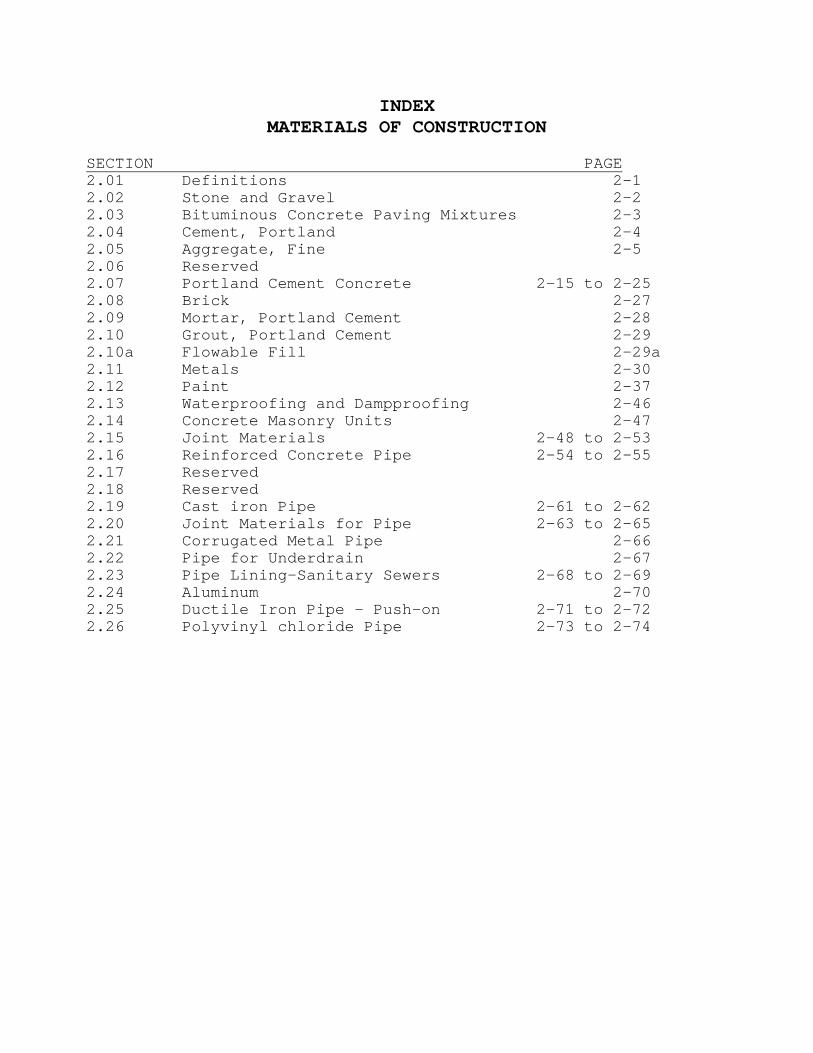
INDEX MATERIALS OF CONSTRUCTION
SECTION PAGE 2.01 Definitions 2-1 2.02 Stone and Gravel 2-2 2.03 Bituminous Concrete Paving Mixtures 2-3 2.04 Cement, Portland 2-4 2.05 Aggregate, Fine 2-5 2.06 Reserved 2.07 Portland Cement Concrete 2-15 to 2-25 2.08 Brick 2-27 2.09 Mortar, Portland Cement 2-28 2.10 Grout, Portland Cement 2-29 2.10a Flowable Fill 2-29a 2.11 Metals 2-30 2.12 Paint 2-37 2.13 Waterproofing and Dampproofing 2-46 2.14 Concrete Masonry Units 2-47 2.15 Joint Materials 2-48 to 2-53 2.16 Reinforced Concrete Pipe 2-54 to 2-55 2.17 Reserved 2.18 Reserved 2.19 Cast iron Pipe 2-61 to 2-62 2.20 Joint Materials for Pipe 2-63 to 2-65 2.21 Corrugated Metal Pipe 2-66 2.22 Pipe for Underdrain 2-67 2.23 Pipe Lining-Sanitary Sewers 2-68 to 2-69 2.24 Aluminum 2-70 2.25 Ductile Iron Pipe - Push-on 2-71 to 2-72 2.26 Polyvinyl chloride Pipe 2-73 to 2-74
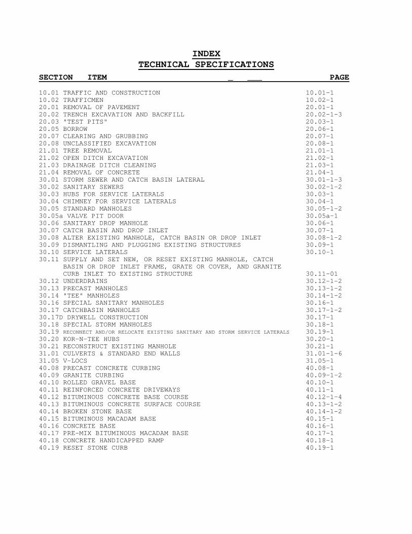
INDEX TECHNICAL SPECIFICATIONS
SECTION ITEM _ ___ PAGE 10.01 TRAFFIC AND CONSTRUCTION 10.01-1 10.02 TRAFFICMEN 10.02-1 20.01 REMOVAL OF PAVEMENT 20.01-1 20.02 TRENCH EXCAVATION AND BACKFILL 20.02-1-3 20.03 "TEST PITS" 20.03-1 20.05 BORROW 20.06-1 20.07 CLEARING AND GRUBBING 20.07-1 20.08 UNCLASSIFIED EXCAVATION 20.08-1 21.01 TREE REMOVAL 21.01-1 21.02 OPEN DITCH EXCAVATION 21.02-1 21.03 DRAINAGE DITCH CLEANING 21.03-1 21.04 REMOVAL OF CONCRETE 21.04-1 30.01 STORM SEWER AND CATCH BASIN LATERAL 30.01-1-3 30.02 SANITARY SEWERS 30.02-1-2 30.03 HUBS FOR SERVICE LATERALS 30.03-1 30.04 CHIMNEY FOR SERVICE LATERALS 30.04-1 30.05 STANDARD MANHOLES 30.05-1-2 30.05a VALVE PIT DOOR 30.05a-1 30.06 SANITARY DROP MANHOLE 30.06-1 30.07 CATCH BASIN AND DROP INLET 30.07-1 30.08 ALTER EXISTING MANHOLE, CATCH BASIN OR DROP INLET 30.08-1-2 30.09 DISMANTLING AND PLUGGING EXISTING STRUCTURES 30.09-1 30.10 SERVICE LATERALS 30.10-1 30.11 SUPPLY AND SET NEW, OR RESET EXISTING MANHOLE, CATCH BASIN OR DROP INLET FRAME, GRATE OR COVER, AND GRANITE CURB INLET TO EXISTING STRUCTURE 30.11-01 30.12 UNDERDRAINS 30.12-1-2 30.13 PRECAST MANHOLES 30.13-1-2 30.14 "TEE" MANHOLES 30.14-1-2 30.16 SPECIAL SANITARY MANHOLES 30.16-1 30.17 CATCHBASIN MANHOLES 30.17-1-2 30.17D DRYWELL CONSTRUCTION 30.17-1 30.18 SPECIAL STORM MANHOLES 30.18-1 30.19 RECONNECT AND/OR RELOCATE EXISTING SANITARY AND STORM SERVICE LATERALS 30.19-1 30.20 KOR-N-TEE HUBS 30.20-1 30.21 RECONSTRUCT EXISTING MANHOLE 30.21-1 31.01 CULVERTS & STANDARD END WALLS 31.01-1-6 31.05 V-LOCS 31.05-1 40.08 PRECAST CONCRETE CURBING 40.08-1 40.09 GRANITE CURBING 40.09-1-2 40.10 ROLLED GRAVEL BASE 40.10-1 40.11 REINFORCED CONCRETE DRIVEWAYS 40.11-1 40.12 BITUMINOUS CONCRETE BASE COURSE 40.12-1-4 40.13 BITUMINOUS CONCRETE SURFACE COURSE 40.13-1-2 40.14 BROKEN STONE BASE 40.14-1-2 40.15 BITUMINOUS MACADAM BASE 40.15-1 40.16 CONCRETE BASE 40.16-1 40.17 PRE-MIX BITUMINOUS MACADAM BASE 40.17-1 40.18 CONCRETE HANDICAPPED RAMP 40.18-1 40.19 RESET STONE CURB 40.19-1
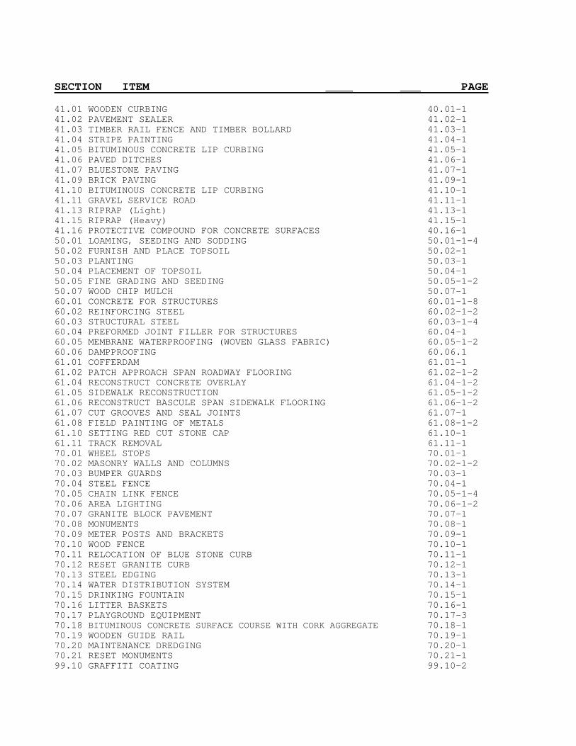
SECTION ITEM ____ ___ PAGE 41.01 WOODEN CURBING 40.01-1 41.02 PAVEMENT SEALER 41.02-1 41.03 TIMBER RAIL FENCE AND TIMBER BOLLARD 41.03-1 41.04 STRIPE PAINTING 41.04-1 41.05 BITUMINOUS CONCRETE LIP CURBING 41.05-1 41.06 PAVED DITCHES 41.06-1 41.07 BLUESTONE PAVING 41.07-1 41.09 BRICK PAVING 41.09-1 41.10 BITUMINOUS CONCRETE LIP CURBING 41.10-1 41.11 GRAVEL SERVICE ROAD 41.11-1 41.13 RIPRAP (Light) 41.13-1 41.15 RIPRAP (Heavy) 41.15-1 41.16 PROTECTIVE COMPOUND FOR CONCRETE SURFACES 40.16-1 50.01 LOAMING, SEEDING AND SODDING 50.01-1-4 50.02 FURNISH AND PLACE TOPSOIL 50.02-1 50.03 PLANTING 50.03-1 50.04 PLACEMENT OF TOPSOIL 50.04-1 50.05 FINE GRADING AND SEEDING 50.05-1-2 50.07 WOOD CHIP MULCH 50.07-1 60.01 CONCRETE FOR STRUCTURES 60.01-1-8 60.02 REINFORCING STEEL 60.02-1-2 60.03 STRUCTURAL STEEL 60.03-1-4 60.04 PREFORMED JOINT FILLER FOR STRUCTURES 60.04-1 60.05 MEMBRANE WATERPROOFING (WOVEN GLASS FABRIC) 60.05-1-2 60.06 DAMPPROOFING 60.06.1 61.01 COFFERDAM 61.01-1 61.02 PATCH APPROACH SPAN ROADWAY FLOORING 61.02-1-2 61.04 RECONSTRUCT CONCRETE OVERLAY 61.04-1-2 61.05 SIDEWALK RECONSTRUCTION 61.05-1-2 61.06 RECONSTRUCT BASCULE SPAN SIDEWALK FLOORING 61.06-1-2 61.07 CUT GROOVES AND SEAL JOINTS 61.07-1 61.08 FIELD PAINTING OF METALS 61.08-1-2 61.10 SETTING RED CUT STONE CAP 61.10-1 61.11 TRACK REMOVAL 61.11-1 70.01 WHEEL STOPS 70.01-1 70.02 MASONRY WALLS AND COLUMNS 70.02-1-2 70.03 BUMPER GUARDS 70.03-1 70.04 STEEL FENCE 70.04-1 70.05 CHAIN LINK FENCE 70.05-1-4 70.06 AREA LIGHTING 70.06-1-2 70.07 GRANITE BLOCK PAVEMENT 70.07-1 70.08 MONUMENTS 70.08-1 70.09 METER POSTS AND BRACKETS 70.09-1 70.10 WOOD FENCE 70.10-1 70.11 RELOCATION OF BLUE STONE CURB 70.11-1 70.12 RESET GRANITE CURB 70.12-1 70.13 STEEL EDGING 70.13-1 70.14 WATER DISTRIBUTION SYSTEM 70.14-1 70.15 DRINKING FOUNTAIN 70.15-1 70.16 LITTER BASKETS 70.16-1 70.17 PLAYGROUND EQUIPMENT 70.17-3 70.18 BITUMINOUS CONCRETE SURFACE COURSE WITH CORK AGGREGATE 70.18-1 70.19 WOODEN GUIDE RAIL 70.19-1 70.20 MAINTENANCE DREDGING 70.20-1 70.21 RESET MONUMENTS 70.21-1 99.10 GRAFFITI COATING 99.10-2
MATERIALS OF CONSTRUCTION SECTION 2.01 DEFINITIONS
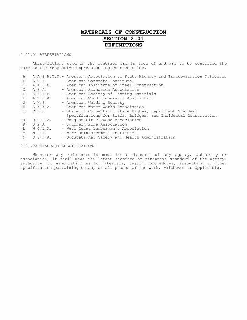
2.01.01 ABBREVIATIONS Abbreviations used in the contract are in lieu of and are to be construed the same as the respective expression represented below. (A) A.A.S.H.T.O.- American Association of State Highway and Transportation Officials (B) A.C.I. - American Concrete Institute (C) A.I.S.C. - American Institute of Steel Construction (D) A.S.A. - American Standards Association (E) A.S.T.M. - American Society of Testing Materials (F) A.W.P.A. - American Wood Preservers Association (G) A.W.S. - American Welding Society (H) A.W.W.A. - American Water Works Association (I) C.H.D. - State of Connecticut State Highway Department Standard Specifications for Roads, Bridges, and Incidental Construction. (J) D.F.P.A. - Douglas Fir Plywood Association (K) S.P.A. - Southern Pine Association (L) W.C.L.A. - West Coast Lumberman's Association (M) W.R.I. - Wire Reinforcement Institute (N) O.S.H.A. - Occupational Safety and Health Administration 2.01.02 STANDARD SPECIFICATIONS Whenever any reference is made to a standard of any agency, authority or association, it shall mean the latest standard or tentative standard of the agency, authority, or association as to materials, testing procedures, inspection or other specification pertaining to any or all phases of the work, whichever is applicable.

2-1
SECTION 2.02
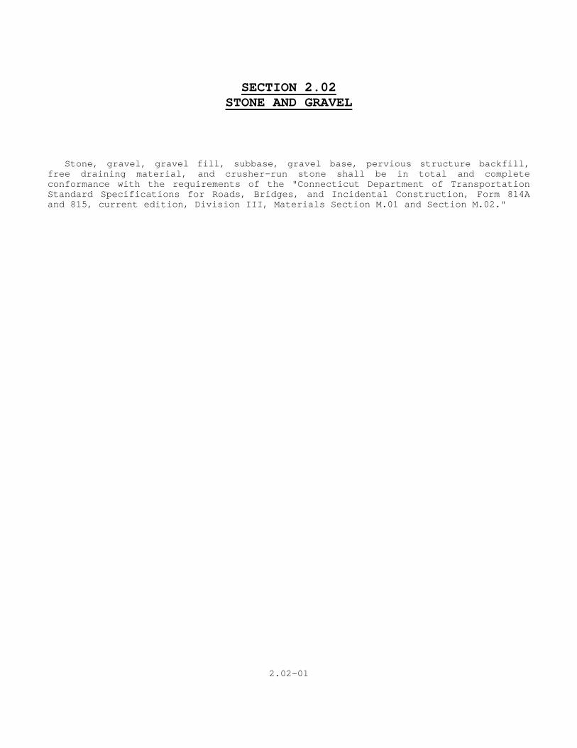
STONE AND GRAVEL Stone, gravel, gravel fill, subbase, gravel base, pervious structure backfill, free draining material, and crusher-run stone shall be in total and complete conformance with the requirements of the "Connecticut Department of Transportation Standard Specifications for Roads, Bridges, and Incidental Construction, Form 814A and 815, current edition, Division III, Materials Section M.01 and Section M.02."
2.02-01
Section 2.03BITUMINOUS CONCRETE PAVING MIXTURES
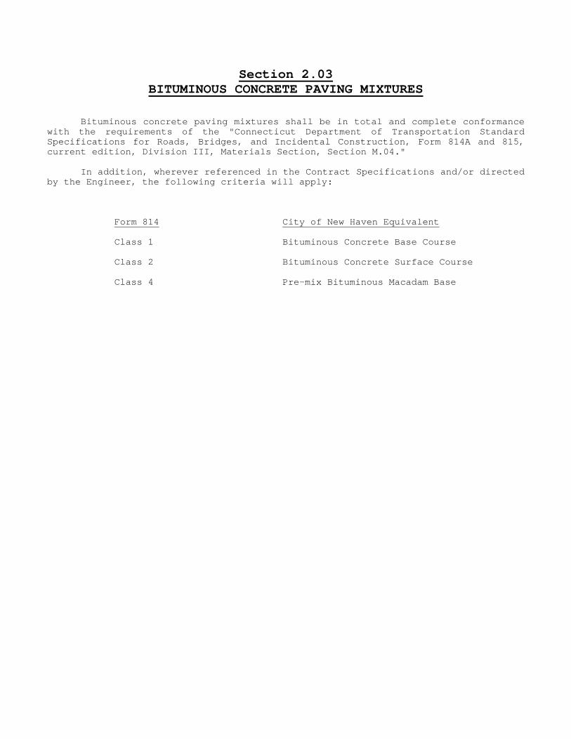
Bituminous concrete paving mixtures shall be in total and complete conformance with the requirements of the "Connecticut Department of Transportation Standard Specifications for Roads, Bridges, and Incidental Construction, Form 814A and 815, current edition, Division III, Materials Section, Section M.04." In addition, wherever referenced in the Contract Specifications and/or directed by the Engineer, the following criteria will apply: Form 814 City of New Haven Equivalent Class 1 Bituminous Concrete Base Course Class 2 Bituminous Concrete Surface Course Class 4 Pre-mix Bituminous Macadam Base

2.03-01
SECTION 2.04 CEMENT, PORTLAND
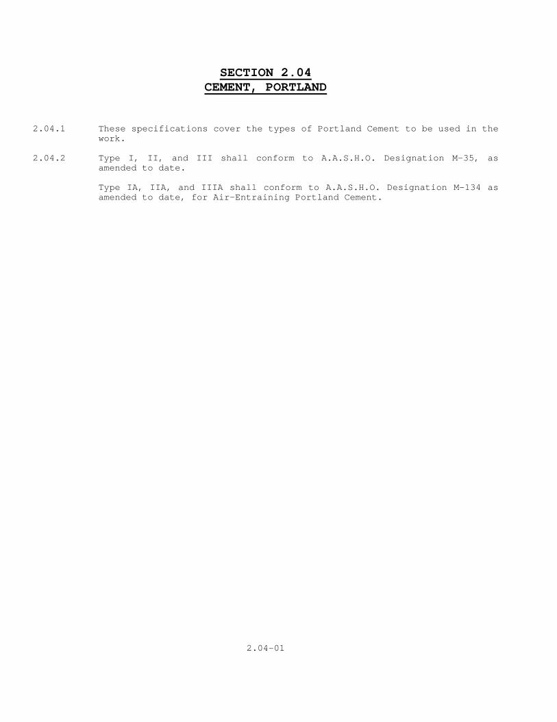
2.04.1 These specifications cover the types of Portland Cement to be used in the
work. 2.04.2 Type I, II, and III shall conform to A.A.S.H.O. Designation M-35, as
amended to date. Type IA, IIA, and IIIA shall conform to A.A.S.H.O. Designation M-134 as amended to date, for Air-Entraining Portland Cement.
2.04-01
2-10
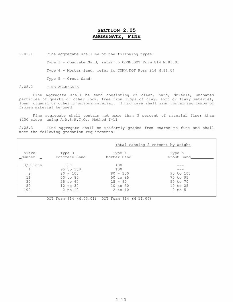
SECTION 2.05 AGGREGATE, FINE
2.05.1 Fine aggregate shall be of the following types: Type 3 - Concrete Sand, refer to CONN.DOT Form 814 M.03.01 Type 4 - Mortar Sand, refer to CONN.DOT Form 814 M.11.04 Type 5 - Grout Sand 2.05.2 FINE AGGREGATE Fine aggregate shall be sand consisting of clean, hard, durable, uncoated particles of quartz or other rock, free from lumps of clay, soft or flaky material, loam, organic or other injurious material. In no case shall sand containing lumps of frozen material be used. Fine aggregate shall contain not more than 3 percent of material finer than #200 sieve, using A.A.S.H.T.O., Method T-11 2.05.3 Fine aggregate shall be uniformly graded from coarse to fine and shall meet the following gradation requirements: Total Passing 2 Percent by Weight Sieve Type 3 Type 4 Type 5 _Number _ Concrete Sand Mortar Sand Grout Sand__________ 3/8 inch 100 100 --- 4 95 to 100 100 --- 8 80 - 100 80 - 100 95 to 100 16 50 to 85 50 to 85 75 to 95 30 25 to 60 25 - 60 50 to 70 50 10 to 30 10 to 30 10 to 25 100 2 to 10 2 to 10 0 to 5 DOT Form 814 (M.03.01) DOT Form 814 (M.11.04)

2-10
2.05-01
SECTION 2.06 PRE-MIX BITUMINOUS MACADAM BASE
2.06.1 The pre-mix bituminous macadam base materials shall consist of course aggregate, fine aggregate and asphalt cement (bitumen) conforming to the requirements of these specifications.
2.06.2 MATERIALS
The materials for his work shall conform to the following requirements:
A. Asphalt Cement: The asphalt cement shall conform to the requirements of A.A.S.H.O. M-20, penetration grade 85-100. The thin film oven test shall be performed in place of the loss on heating test. The requirements for the residue from the thin-film oven test shall be as follows:
The penetration shall be not less than 50 percent of the original penetration, and the ductility shall be not less than 75 cms.
In addition, the Saybolt-Furol viscosity at 275 degrees F. shall be not less than 150 seconds. A.S.T.M. Method E-102 shall be used.
B. Coarse Aggregate: Coarse aggregate shall conform to the requirements of Section 2.07.02 of these specifications.
C. Fine Aggregate: Fine aggregate shall consist of natural sand, stone sand, or screening or any combination thereof. The fine aggregate shall be limited to material 95 percent of which passes a No. 4 sieve having square openings and not more than 8 percent of which passes a No. 200 sieve. The material shall be free from clay, loam, and foreign materials. The Engineer reserves the right to reject material, which does not conform to the requirements of Section 2.02.2 of these specifications for plasticity. When screenings are blended they shall be free from coatings of fine dust after drying.
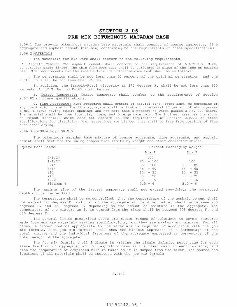
2.06.3 FORMULA FOR JOB MIX
The bituminous macadam base mixture of coarse aggregate, fine aggregate, and asphalt cement shall meet the following composition limits by weight and other characteristics:
Square Mesh Sieve ___ _________ Percent Passing by Weight
Mix A Mix B
2-1/2" 100 1-1/2" 80 - 100 100 3/4" 55 - 80 60 - 85 3/8" 35 - 60 35 - 65 #10 15 - 35 15 - 35 #40 5 - 20 5 - 25 #200 2 - 10 3 - 10 Bitumen % 3.5 - 6 3.5 - 6
The maximum size of the largest aggregate shall not exceed two-thirds the compacted depth of the course laid.
The temperature shall be so controlled, that the temperature of the asphalt cement shall not exceed 325 degrees F. and that of the aggregate at the drier outlet shall be between 250 degrees F. and 350 degrees F. depending on the amount of moisture in the aggregate. The temperature of the mixture as it is dumped from the mixer shall be between 225 degrees F. and 300 degrees F.
The general limits prescribed above are master ranges of tolerance to govern mixtures made from any raw materials meeting specifications, and they are maximum and minimum, for all cases. A closer control appropriate to the materials is required in accordance with the job mix formula. Such job mix formula shall show the bitumen expressed as a percentage of the total mixture and the individual fractions of the aggregate expressed as percentage of the total weight of the aggregate.
The job mix formula shall indicate in writing the single definite percentage for each sieve fraction of aggregate, and for asphalt chosen as the fixed mean in each instance, and also the temperature of completed mixture taken as it is dumped from the mixer. The source and locations of all materials shall be included with the job mix formula.
2.06-1
11152242.06-1
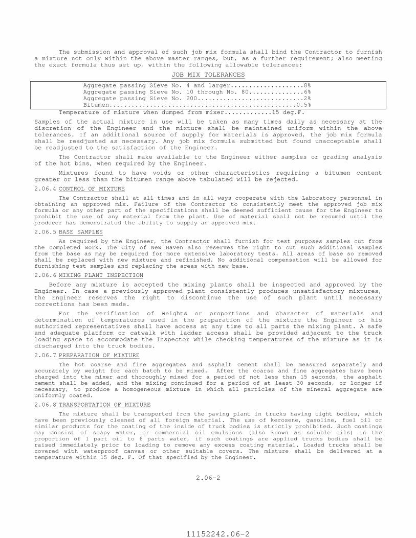
The submission and approval of such job mix formula shall bind the Contractor to furnish a mixture not only within the above master ranges, but, as a further requirement; also meeting the exact formula thus set up, within the following allowable tolerances:
JOB MIX TOLERANCES
Aggregate passing Sieve No. 4 and larger....................8% Aggregate passing Sieve No. 10 through No. 80...............6% Aggregate passing Sieve No. 200.............................2% Bitumen...................................................0.5% Temperature of mixture when dumped from mixer.............15 deg.F.
Samples of the actual mixture in use will be taken as many times daily as necessary at the discretion of the Engineer and the mixture shall be maintained uniform within the above tolerances. If an additional source of supply for materials is approved, the job mix formula shall be readjusted as necessary. Any job mix formula submitted but found unacceptable shall be readjusted to the satisfaction of the Engineer.
The Contractor shall make available to the Engineer either samples or grading analysis of the hot bins, when required by the Engineer.
Mixtures found to have voids or other characteristics requiring a bitumen content greater or less than the bitumen range above tabulated will be rejected.
2.06.4 CONTROL OF MIXTURE
The Contractor shall at all times and in all ways cooperate with the Laboratory personnel in obtaining an approved mix. Failure of the Contractor to consistently meet the approved job mix formula or any other part of the specifications shall be deemed sufficient cause for the Engineer to prohibit the use of any material from the plant. Use of material shall not be resumed until the producer has demonstrated the ability to supply an approved mix.
2.06.5 BASE SAMPLES
As required by the Engineer, the Contractor shall furnish for test purposes samples cut from the completed work. The City of New Haven also reserves the right to cut such additional samples from the base as may be required for more extensive laboratory tests. All areas of base so removed shall be replaced with new mixture and refinished. No additional compensation will be allowed for furnishing test samples and replacing the areas with new base.
2.06.6 MIXING PLANT INSPECTION
Before any mixture is accepted the mixing plants shall be inspected and approved by the Engineer. In case a previously approved plant consistently produces unsatisfactory mixtures, the Engineer reserves the right to discontinue the use of such plant until necessary corrections has been made.
For the verification of weights or proportions and character of materials and determination of temperatures used in the preparation of the mixture the Engineer or his authorized representatives shall have access at any time to all parts the mixing plant. A safe and adequate platform or catwalk with ladder access shall be provided adjacent to the truck loading space to accommodate the Inspector while checking temperatures of the mixture as it is discharged into the truck bodies.
2.06.7 PREPARATION OF MIXTURE
The hot coarse and fine aggregates and asphalt cement shall be measured separately and accurately by weight for each batch to be mixed. After the coarse and fine aggregates have been charged into the mixer and thoroughly mixed for a period of not less than 15 seconds, the asphalt cement shall be added, and the mixing continued for a period of at least 30 seconds, or longer if necessary, to produce a homogeneous mixture in which all particles of the mineral aggregate are uniformly coated.
2.06.8 TRANSPORTATION OF MIXTURE
The mixture shall be transported from the paving plant in trucks having tight bodies, which have been previously cleaned of all foreign material. The use of kerosene, gasoline, fuel oil or similar products for the coating of the inside of truck bodies is strictly prohibited. Such coatings may consist of soapy water, or commercial oil emulsions (also known as soluble oils) in the proportion of 1 part oil to 6 parts water, if such coatings are applied trucks bodies shall be raised immediately prior to loading to remove any excess coating material. Loaded trucks shall be covered with waterproof canvas or other suitable covers. The mixture shall be delivered at a temperature within 15 deg. F. Of that specified by the Engineer.
2.06-2
11152242.06-2
SECTION 2.07 PORTLAND CEMENT CONCRETE
Portland cement concrete shall be in total and complete conformance with the requirements of the “Connecticut Department of Transportation Standard” FORM 816 or the most current edition, Division III, Materials Section, Section M.03”.
2.07-01
1
SECTION 2.08 BRICK
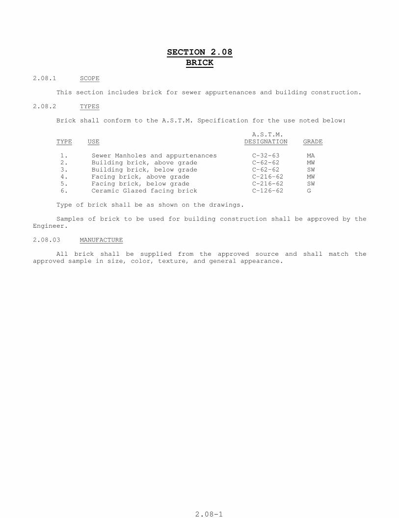
2.08.1 SCOPE This section includes brick for sewer appurtenances and building construction. 2.08.2 TYPES Brick shall conform to the A.S.T.M. Specification for the use noted below: A.S.T.M. TYPE USE DESIGNATION GRADE 1. Sewer Manholes and appurtenances C-32-63 MA 2. Building brick, above grade C-62-62 MW 3. Building brick, below grade C-62-62 SW 4. Facing brick, above grade C-216-62 MW 5. Facing brick, below grade C-216-62 SW 6. Ceramic Glazed facing brick C-126-62 G Type of brick shall be as shown on the drawings. Samples of brick to be used for building construction shall be approved by the Engineer. 2.08.03 MANUFACTURE All brick shall be supplied from the approved source and shall match the approved sample in size, color, texture, and general appearance.
2.08-1

2.08-01
2.08-2
SECTION 2.09 MORTAR, PORTLAND CEMENT
2.09.1 This section describes Portland cement mortar. 2.09.2 (A) Mortar shall be of the following types: Type 1 - Mortar, Proportions 1:2-1/2 Type 2 - Mortar, Proportions 1:2 Type 3 - Mortar, Proportions 1:1 (B) Unless otherwise specified Type I shall be used. 2.09.3 (A) Mortar shall consist of sand mixed with Portland cement and water in definite proportions so as to produce a stiff mixture. Proportions shall be based on rodded volumetric measurement of dry material. When aggregates are measured in the damp-loose condition, they will occupy greater volume than when dry-rodded and the percentage bulking shall be determined by test. Approximate average bulking value for sand is 25 percent. (B) Portland cement shall comply with the requirements of Section 2.07. Type II cement shall be used, except where Type III cement is specified. (C) Sand shall comply with the requirements of Section 2.05, Type 4, Mortar Sand. (D) Water shall be drawn from the public water supply system, or equivalent water from some other source. In no case shall muddy water or water contaminated with material deleterious to the concrete be used. 2.09.4 (A) Proportioning Ingredients: The materials shall be measured accurately by volume. (B) Mixing Ingredients: Mortar in amounts less than 1/4 cu. yd. may be mixed in a suitable box or on a tight platform, however, never upon the pavement or ground. The cement and sand shall be thoroughly mixed dry, until the mixture has a uniform color. Clean, fresh water shall then be added and the mass worked until a mortar, which is uniform and of the required consistency, is produced. The mortar shall be mixed in no greater quantity than is required for the work in hand. Mortar that has set sufficiently to require retempering shall not be used. The ingredient materials, after measuring, shall be mixed in an approved rotating drum type batch mixer. Mixing shall be for a period of not less than 1-1/2 minutes at a rate of not less than 14 or more than 22 R.P.M. and shall be continued until a homogeneous mixture is produced. 2.09.5 The mixing and use of mortar in freezing weather shall be subject to the same requirements as herein specified for mixing and placing concrete under similar conditions.
11152242.09-1

2.09-1
11152242.09-2
SECTION 2.10 GROUT, PORTLAND CEMENT
2.10.1 This section described Portland cement grout. 2.10.2 (A) Grout shall be of the following types: Type 1 - Grout, Cement Type 2 - Grout, Cement and Sand 2.10.3 (A) Type 1 - Cement Grout shall consist of neat cement and water mixed to a consistency suitable for work on hand. (B) Type 2 - Cement and Sand Grout shall consist of sand mixed with Portland cement and water in definite proportions so a to produce a mixture of cream like consistency containing 1 part of cement by volume and not more than 1 part of sand by volume, based on rodded volumetric measurement of dry material. When aggregates are measured in the damp loose condition, they will occupy greater volume than when dry-rodded and the percentage bulking shall be determined by test. Approximate average bulking value for sand is 25 percent. (C) Portland cement shall comply with the requirements of Section 2.07. Type II Cement shall be used, except where Type III cement is specified. Cement for grout shall be screened to remove the coarser particles. (D) Sand shall comply with the requirement of Section 2.05, Type 5, Grout Sand. (E) Water shall be drawn from the public water supply system, or equivalent water from some other source. In no case shall muddy water or water contaminated with material deleterious to the concrete be used. 2.10.4 (A) Proportioning Ingredients: The materials shall be measured accurately by volume. (B) Mixing Ingredients: Grout in amounts less than 1/4 cu. yd. may be mixed in a suitable box or on a tight platform, however never upon the pavement or ground. The cement and sand for Type 2 Grout shall be thoroughly mixed dry, until the mixture has a uniform color. Clean, fresh water shall then be added and the mass worked until a mixture, which is uniform and of the required consistency, is produced. The grout shall be mixed in no greater quantity than is required for the work in hand, and any that has set sufficiently to require retempering shall not be used. Ingredient materials, after measuring, shall be mixed in an approved type mixer. Mixing shall be for a period of not less than 1-1/2 minutes at a rate of not less than 14 nor more than 22 R.P.M. and shall be continued until a homogeneous mixture is produced. The grout shall be kept constantly agitated until used. 2.10.5 The mixing and use of grout in freezing weather shall be subject to the same requirements as herein specified for mixing and placing concrete under similar conditions.
2.10-01
2.10-1
SECTION 2.10a FLOWABLE FILL
2.10a.1 This section describes Flowable Fill. 2.10a.2 Flowable fill shall consist of sand mixed with Portland cement and water in definite proportions so a to produce a mixture of a consistency containing 75 pounds of cement, 2350 pounds of sand, 38 gallons of water and 1 unit of flow agent (RHEOCELL RHEOFILL). (a)Portland cement shall comply with the requirements of Section 2.07. Type II Cement shall be used, except where Type III cement is specified. Cement for grout shall be screened to remove the coarser particles. (b) Sand shall comply with the requirement of Section 2.05, Type 5, Grout Sand. (c) Water shall be drawn from the public water supply system, or equivalent water from some other source. In no case shall muddy water or water contaminated with material deleterious to the concrete be used. 2.10a.3 The mixing and use of fill in freezing weather shall be subject to the same requirements as herein specified for mixing and placing concrete under similar conditions.
2.10-1

2.10a-01
2.10-2
SECTION 2.11 METALS
Metals shall be in total and complete conformance with the requirements of the "Connecticut Department of Transportation Standard Specifications for Roads, Bridges, and Incidental Construction, Form 814, Current edition, Division III, Materials Section, Section M.06."
2-30
11152242.11-1
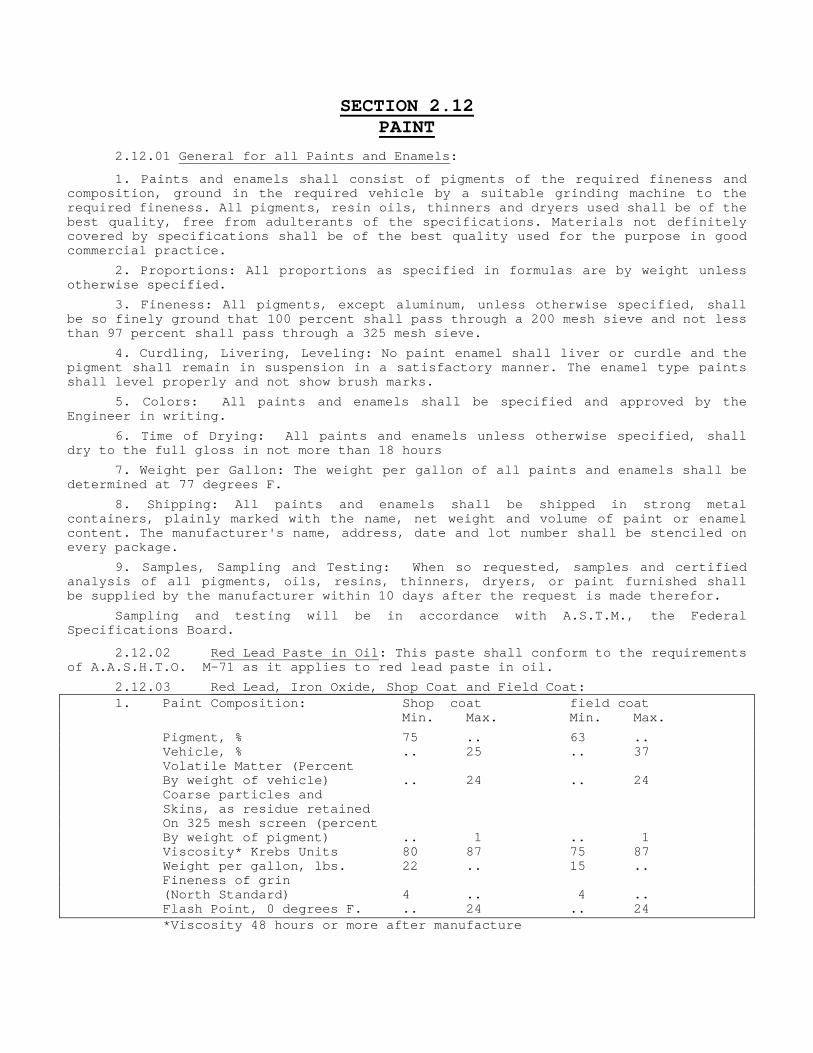
SECTION 2.12 PAINT
2.12.01 General for all Paints and Enamels:
1. Paints and enamels shall consist of pigments of the required fineness and composition, ground in the required vehicle by a suitable grinding machine to the required fineness. All pigments, resin oils, thinners and dryers used shall be of the best quality, free from adulterants of the specifications. Materials not definitely covered by specifications shall be of the best quality used for the purpose in good commercial practice.
2. Proportions: All proportions as specified in formulas are by weight unless otherwise specified.
3. Fineness: All pigments, except aluminum, unless otherwise specified, shall be so finely ground that 100 percent shall pass through a 200 mesh sieve and not less than 97 percent shall pass through a 325 mesh sieve.
4. Curdling, Livering, Leveling: No paint enamel shall liver or curdle and the pigment shall remain in suspension in a satisfactory manner. The enamel type paints shall level properly and not show brush marks.
5. Colors: All paints and enamels shall be specified and approved by the Engineer in writing.
6. Time of Drying: All paints and enamels unless otherwise specified, shall dry to the full gloss in not more than 18 hours
7. Weight per Gallon: The weight per gallon of all paints and enamels shall be determined at 77 degrees F.
8. Shipping: All paints and enamels shall be shipped in strong metal containers, plainly marked with the name, net weight and volume of paint or enamel content. The manufacturer's name, address, date and lot number shall be stenciled on every package.
9. Samples, Sampling and Testing: When so requested, samples and certified analysis of all pigments, oils, resins, thinners, dryers, or paint furnished shall be supplied by the manufacturer within 10 days after the request is made therefor.
Sampling and testing will be in accordance with A.S.T.M., the Federal Specifications Board.
2.12.02 Red Lead Paste in Oil: This paste shall conform to the requirements of A.A.S.H.T.O. M-71 as it applies to red lead paste in oil.
2.12.03 Red Lead, Iron Oxide, Shop Coat and Field Coat: 1. Paint Composition: Shop coat field coat Min. Max. Min. Max.
Pigment, % 75 .. 63 .. Vehicle, % .. 25 .. 37 Volatile Matter (Percent By weight of vehicle) .. 24 .. 24 Coarse particles and Skins, as residue retained On 325 mesh screen (percent By weight of pigment) .. 1 .. 1 Viscosity* Krebs Units 80 87 75 87 Weight per gallon, lbs. 22 .. 15 .. Fineness of grin (North Standard) 4 .. 4 .. Flash Point, 0 degrees F. .. 24 .. 24 *Viscosity 48 hours or more after manufacture
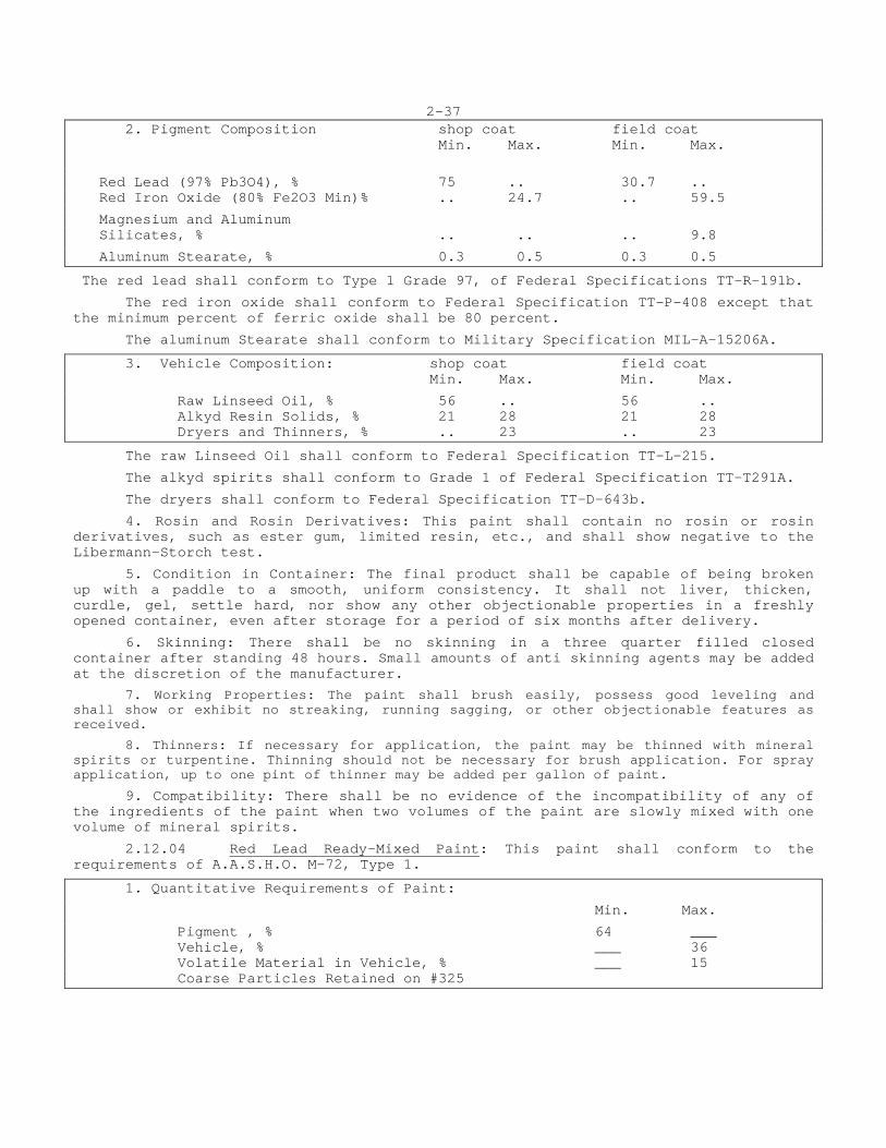
2-37 2. Pigment Composition shop coat field coat Min. Max. Min. Max.
Red Lead (97% Pb3O4), % 75 .. 30.7 .. Red Iron Oxide (80% Fe2O3 Min)% .. 24.7 .. 59.5
Magnesium and Aluminum Silicates, % .. .. .. 9.8
Aluminum Stearate, % 0.3 0.5 0.3 0.5
The red lead shall conform to Type 1 Grade 97, of Federal Specifications TT-R-191b.
The red iron oxide shall conform to Federal Specification TT-P-408 except that the minimum percent of ferric oxide shall be 80 percent.
The aluminum Stearate shall conform to Military Specification MIL-A-15206A.
3. Vehicle Composition: shop coat field coat Min. Max. Min. Max.
Raw Linseed Oil, % 56 .. 56 .. Alkyd Resin Solids, % 21 28 21 28 Dryers and Thinners, % .. 23 .. 23
The raw Linseed Oil shall conform to Federal Specification TT-L-215.
The alkyd spirits shall conform to Grade 1 of Federal Specification TT-T291A.
The dryers shall conform to Federal Specification TT-D-643b.
4. Rosin and Rosin Derivatives: This paint shall contain no rosin or rosin derivatives, such as ester gum, limited resin, etc., and shall show negative to the Libermann-Storch test.
5. Condition in Container: The final product shall be capable of being broken up with a paddle to a smooth, uniform consistency. It shall not liver, thicken, curdle, gel, settle hard, nor show any other objectionable properties in a freshly opened container, even after storage for a period of six months after delivery.
6. Skinning: There shall be no skinning in a three quarter filled closed container after standing 48 hours. Small amounts of anti skinning agents may be added at the discretion of the manufacturer.
7. Working Properties: The paint shall brush easily, possess good leveling and shall show or exhibit no streaking, running sagging, or other objectionable features as received.
8. Thinners: If necessary for application, the paint may be thinned with mineral spirits or turpentine. Thinning should not be necessary for brush application. For spray application, up to one pint of thinner may be added per gallon of paint.
9. Compatibility: There shall be no evidence of the incompatibility of any of the ingredients of the paint when two volumes of the paint are slowly mixed with one volume of mineral spirits.
2.12.04 Red Lead Ready-Mixed Paint: This paint shall conform to the requirements of A.A.S.H.O. M-72, Type 1.
1. Quantitative Requirements of Paint:
Min. Max.
Pigment , % 64 ___ Vehicle, % ___ 36 Volatile Material in Vehicle, % ___ 15 Coarse Particles Retained on #325
2-38
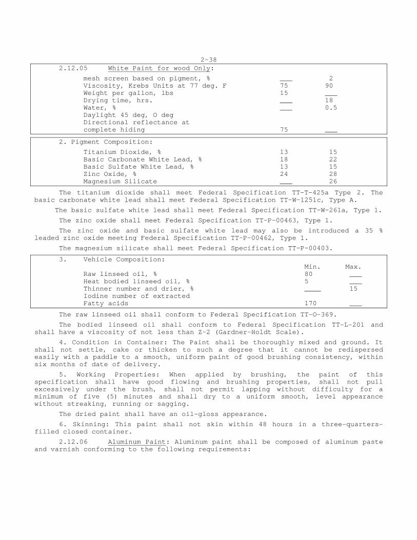
2.12.05 White Paint for wood Only:
mesh screen based on pigment, % ___ 2 Viscosity, Krebs Units at 77 deg. F 75 90 Weight per gallon, lbs 15 ___ Drying time, hrs. ___ 18 Water, % ___ 0.5 Daylight 45 deg, O deg Directional reflectance at complete hiding 75 ___
2. Pigment Composition:
Titanium Dioxide, % 13 15 Basic Carbonate White Lead, % 18 22 Basic Sulfate White Lead, % 13 15 Zinc Oxide, % 24 28 Magnesium Silicate ___ 26
The titanium dioxide shall meet Federal Specification TT-T-425a Type 2. The basic carbonate white lead shall meet Federal Specification TT-W-1251c, Type A.
The basic sulfate white lead shall meet Federal Specification TT-W-261a, Type 1.
The zinc oxide shall meet Federal Specification TT-P-00463, Type 1.
The zinc oxide and basic sulfate white lead may also be introduced a 35 % leaded zinc oxide meeting Federal Specification TT-P-00462, Type 1.
The magnesium silicate shall meet Federal Specification TT-P-00403.
3. Vehicle Composition: Min. Max. Raw linseed oil, % 80 ___ Heat bodied linseed oil, % 5 ___ Thinner number and drier, % ____ 15 Iodine number of extracted Fatty acids 170 ___
The raw linseed oil shall conform to Federal Specification TT-O-369.
The bodied linseed oil shall conform to Federal Specification TT-L-201 and shall have a viscosity of not less than Z-2 (Gardner-Holdt Scale).
4. Condition in Container: The Paint shall be thoroughly mixed and ground. It shall not settle, cake or thicken to such a degree that it cannot be redispersed easily with a paddle to a smooth, uniform paint of good brushing consistency, within six months of date of delivery.
5. Working Properties: When applied by brushing, the paint of this specification shall have good flowing and brushing properties, shall not pull excessively under the brush, shall not permit lapping without difficulty for a minimum of five (5) minutes and shall dry to a uniform smooth, level appearance without streaking, running or sagging.
The dried paint shall have an oil-gloss appearance.
6. Skinning: This paint shall not skin within 48 hours in a three-quarters-filled closed container.
2.12.06 Aluminum Paint: Aluminum paint shall be composed of aluminum paste and varnish conforming to the following requirements:
2-39
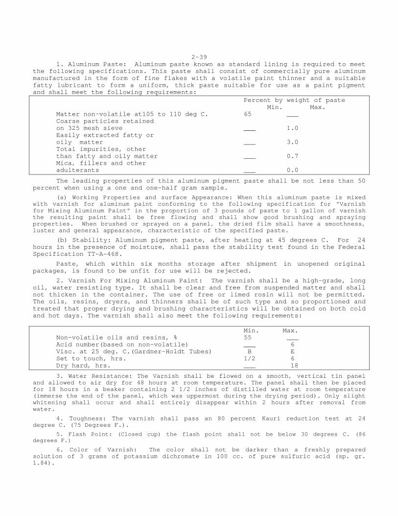
1. Aluminum Paste: Aluminum paste known as standard lining is required to meet the following specifications. This paste shall consist of commercially pure aluminum manufactured in the form of fine flakes with a volatile paint thinner and a suitable fatty lubricant to form a uniform, thick paste suitable for use as a paint pigment and shall meet the following requirements: Percent by weight of paste Min. Max. Matter non-volatile at105 to 110 deg C. 65 ___ Coarse particles retained on 325 mesh sieve ___ 1.0 Easily extracted fatty or oily matter ___ 3.0 Total impurities, other than fatty and oily matter ___ 0.7 Mica, fillers and other adulterants ___ 0.0
The leading properties of this aluminum pigment paste shall be not less than 50 percent when using a one and one-half gram sample.
(a) Working Properties and surface Appearance: When this aluminum paste is mixed with varnish for aluminum paint conforming to the following specification for "Varnish for Mixing Aluminum Paint" in the proportion of 3 pounds of paste to 1 gallon of varnish the resulting paint shall be free flowing and shall show good brushing and spraying properties. When brushed or sprayed on a panel, the dried film shall have a smoothness, luster and general appearance, characteristic of the specified paste.
(b) Stability: Aluminum pigment paste, after heating at 45 degrees C. For 24 hours in the presence of moisture, shall pass the stability test found in the Federal Specification TT-A-468.
Paste, which within six months storage after shipment in unopened original packages, is found to be unfit for use will be rejected.
2. Varnish For Mixing Aluminum Paint: The varnish shall be a high-grade, long oil, water resisting type. It shall be clear and free from suspended matter and shall not thicken in the container. The use of free or limed rosin will not be permitted. The oils, resins, dryers, and thinners shall be of such type and so proportioned and treated that proper drying and brushing characteristics will be obtained on both cold and hot days. The varnish shall also meet the following requirements: Min. Max. Non-volatile oils and resins, % 55 ___ Acid number(based on non-volatile) ___ 6 Visc. at 25 deg. C.(Gardner-Holdt Tubes) B E Set to touch, hrs. 1/2 6 Dry hard, hrs. ___ 18
3. Water Resistance: The Varnish shall be flowed on a smooth, vertical tin panel and allowed to air dry for 48 hours at room temperature. The panel shall then be placed for 18 hours in a beaker containing 2 1/2 inches of distilled water at room temperature (immerse the end of the panel, which was uppermost during the drying period). Only slight whitening shall occur and shall entirely disappear within 2 hours after removal from water.
4. Toughness: The varnish shall pass an 80 percent Kauri reduction test at 24 degree C. (75 Degrees F.).
5. Flash Point: (Closed cup) the flash point shall not be below 30 degrees C. (86 degrees F.)
6. Color of Varnish: The color shall not be darker than a freshly prepared solution of 3 grams of potassium dichromate in 100 cc. of pure sulfuric acid (sp. gr. 1.84).
2-40 7. Working Properties: When mixed by stirring with 3 pounds of aluminum paste to 1 gallon of varnish, the paint shall show satisfactory spreading qualities and shall not run or sag when applied to a vertical surface.
A paint made with this paste and this varnish, the paint shall be free flowing, shall be of good brushing consistency and shall show good leafing properties. The dried film shall be smooth, shall have good luster and general appearance.
The paint shall set slowly enough to be brushed without Laps during hot weather. When brushed on a smooth vertical tin panel it shall dry within 18 hours to an apparently continuous metallic coating without running or sagging.
The component part of aluminum paint, that is the varnish and the aluminum paste, shall be shipped to the project in separate containers, so that they may be sampled individually and then combined under the supervision of the Engineer.
When two coats of aluminum paint are specified the first or undercoat shall be tinted with Prussian blue. From 4 to 6 ounces of tinting paste shall be used to each gallon of paint of A.A.S.H.O. M-131.
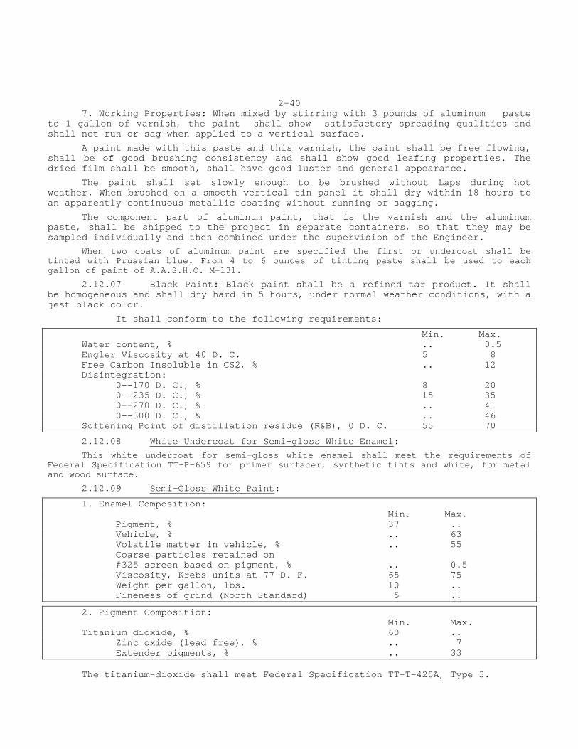
2.12.07 Black Paint: Black paint shall be a refined tar product. It shall be homogeneous and shall dry hard in 5 hours, under normal weather conditions, with a jest black color.
It shall conform to the following requirements:
Min. Max. Water content, % .. 0.5 Engler Viscosity at 40 D. C. 5 8 Free Carbon Insoluble in CS2, % .. 12 Disintegration: 0--170 D. C., % 8 20 0--235 D. C., % 15 35 0--270 D. C., % .. 41 0--300 D. C., % .. 46 Softening Point of distillation residue (R&B), 0 D. C. 55 70
2.12.08 White Undercoat for Semi-gloss White Enamel:
This white undercoat for semi-gloss white enamel shall meet the requirements of Federal Specification TT-P-659 for primer surfacer, synthetic tints and white, for metal and wood surface.
9 2.12.0 Semi-Gloss White Paint:
1. Enamel Composition: Min. Max. Pigment, % 37 .. Vehicle, % .. 63 Volatile matter in vehicle, % .. 55 Coarse particles retained on #325 screen based on pigment, % .. 0.5 Viscosity, Krebs units at 77 D. F. 65 75 Weight per gallon, lbs. 10 .. Fineness of grind (North Standard) 5 ..
2. Pigment Composition: Min. Max. Titanium dioxide, % 60 .. Zinc oxide (lead free), % .. 7 Extender pigments, % .. 33 The titanium-dioxide shall meet Federal Specification TT-T-425A, Type 3.
2-41
The lead free zinc oxide shall meet Federal Specification TT-P-00463 French process.
The extender pigments shall consist of any one of the following or combination thereof: Magnesium silicate, barium sulfate of diatomaceous silica. A ratio of 50 % magnesium silicate and 50 % diatomaceous silica has been found to be satisfactory in order to produce the desired semi-gloss appearance.
3. Vehicle: The vehicle shall contain not less than 45% solids by weight and shall be composed of a long oil Soya modified alkyd resin solution or solutions, petroleum solvent thinners and dryers. Rosin or rosin derivatives shall not be present. The alkyd resin solution or solutions shall conform to the Federal Specification TT-r-266 Type 1, Class A. 4. Specular gloss: The enamel shall be flowed on a tin panel and allowed to dry for 24 hours before measuring. The Specular gloss at 60 degree angle of incident, A.S.T.M. D-253 shall be between 35 and 45. 5. Setting and Drying Time: This enamel shall set to touch in less than 5 hours. It shall dry hard and tough in not more than 24 hours. 6. Flash Point: The flash point shall not be below 30 degrees C. (86 Deg. F.) when determined by the Pensky-Martin closed flash tester.
7. Water Resistance: The enamel shall be flowed on a tin panel and allowed to dry for 48 hours. After being immersed for 18 hours in distilled water, it shall show no blistering or wrinkles upon removal and shall show no dulling or change in color after two hours recovery. 8. Skinning: This enamel shall not skin over within 48 hours in a three-quarter filled closed container. Small amounts of anti-skinning agents, wetting agents, suspension agents and anti-drier absorption agents may be added at the discretion of the manufacturer. 9. Working Properties: The enamel shall be well ground, shall not settle in the container and shall be capable of being broken up with a paddle to a smooth uniform enamel of good brushing consistency and shall have good flowing, covering and leveling properties. 2.12.10 Masonry Paint: Masonry prime coat shall be "Surfa-Sele" #713. White coat and finish coat shall be as specified and approved in writing by the Engineer, all as manufactured by Rust-Oleum Corporation or approved equal.

2-42
SECTION 2.13WATERPROOFING AND DAMPPROOFING
2.13.1 WATERPROOFING The materials for this work shall conform to the following requirements: 1. Waterproofing Asphalt: For woven cotton fabric, the asphalt shall conform to the requirements of A.A.S.H.O. M-115. Unless otherwise specified, Type B, for use below ground, shall be used. For woven glass fabric, the seal coat material shall be an asphalt conforming to A.S.T.M. D-449, Type C. Asphalt Flashing Cement shall be a compound of asbestos and asphalt conforming to the requirements of Federal Specification SS-C-153, Type I. Primer for use with asphalt in waterproofing shall conform to the requirements of A.A.S.H.O. M-116. 2. Fabric: Woven cotton fabric shall conform to the requirements of A.A.S.H.O. M-117. The saturant shall be asphalt or pitch to conform with the cementing material. Woven glass fabric saturated with asphalt shall conform to the requirements of Federal Specification HH-C-00466, except that the requirements for the ratio of benzene-soluble coating to glass cloth shall be waived. 2.13.2 DAMPPROOFING The materials for this work shall conform to the requirements of asphalt for primer and seal coat for woven cotton fabric, as stipulated in Article 2.13.1.
2.13-1

2.13-1
2.13-2
SECTION 2.14 CONCRETE MASONRY UNITS
2.14.01 MANHOLES AND CATCHBASINS Masonry units used for construction of manholes or catch basins shall conform to the requirements of A.S.T.M. Designation C 139-63. 2.14.02 HOLLOW LOAD BEARING UNITS Hollow Masonry units used for construction of walls, footings and all other load bearing construction shall conform to the requirements of A.S.T.M. Designation C90-59. 2.14.03 SOLID LOAD BEARING UNITS Solid masonry units used for construction of walls and all load bearing construction shall conform to A.S.T.M. Designation C145-59 for Grade B.
2.14-1
SECTION 2.15JOINT MATERIALS
2.15.01 PREFORMED CORK EXPANSION JOINT FILLER
Preformed Cork Expansion Joint Filler, Type I, shall conform to the requirement of A.A.S.H.O. Spec. M 153-54 Type I.
Unless otherwise required by these specifications or the plans, this material shall be used in expansion joints of all walls, bridges, box culverts, buildings and other construction not covered by other articles of this Section.
2.15.02 SELF EXPANDING PREFORMED CORK EXPANSION JOINT FILLER
Self-Expanding Preformed Cork Expansion Joint Filler, shall conform to the requirements of A.A.S.H.O. Spec. M153-54, Type II.
Unless otherwise required by these specifications or plans, this material shall be used in expansion joints of sewage disposal and water works structures.
2.15.03 PREMOULDED BITUMINOUS-IMPREGNATED CANE FIBER BOARD JOINT FILLER
Pre-molded non-extruding bituminous impregnated cane fiberboard meeting the following requirements and specifications.
a. Core stock: The filler core material shall be made of long tough fibers fitted together to form a rigid board weighing not more than 16 lbs. per cu. ft.
b. Asphalt Content: The core stock shall be uniformly impregnated throughout its cross-section with at least 35% and not more than 50% by weight with a durable asphaltic compound.
c. Compressibility: The load required to compress a test specimen to 50% of its thickness shall be between 100 and 750 lbs. per sq. in.
d. Resiliency: A test specimen shall be given three applications of a load sufficient to compress the material to 50% of its original thickness. The load shall be released and the compression repeated three times. At the end of an hour after the third application the material shall have recovered to at least 70% of its thickness before test.
e. Extrusion: Specimen confined on three sides shall be compressed to 50% of its original thickness. The amount of extrusion of the free edge shall not exceed 1/8".
f. Loss in Weight: This same specimen when compressed to half its original thickness shall show a loss of asphaltic compound not more than 3% by weight of the original test specimen.
The joint filler shall be "Flexcell" Bituminous - Impregnated Cane FiberBoard as manufactured by The Celotex Corporation, Chicago, Illinois, or approved equal.
Unless otherwise required by these specifications or plans, this material shall be used in expansion joints of sidewalks and other slabs resting on the ground.
2.15.04 PREFORMED BITUMINOUS JOINT FILLER
Preformed Bituminous Joint Filler shall be the bituminous cellular type and shall conform to the requirements of A.A.S.H.O. M-153-54 Type III.
This material shall not be used unless specifically called for in the specifications, contract plans or by the Engineer.
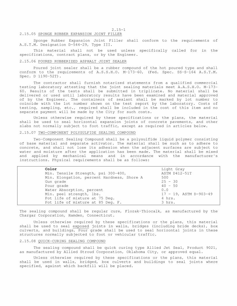
2.15-1 2.15.05 SPONGE RUBBER EXPANSION JOINT FILLER
Sponge Rubber Expansion Joint Filler shall conform to the requirements of A.S.T.M. Designation D-544-29, Type III.
This material shall not be used unless specifically called for in the specifications, contract plans, or by the Engineer.
2.15.06 POURED RUBBERIZED ASPHALT JOINT SEALER
Poured joint sealer shall be a rubber compound of the hot poured type and shall conform to the requirements of A.S.S.H.O. M-173-60, (Fed. Spec. SS-S-164 A.S.T.M. Spec. D 1190-52T).
The contractor shall furnish notarized statements from a qualified commercial testing laboratory attesting that the joint sealing materials meet A.A.S.H.O. M-173-60. Results of the tests shall be submitted in triplicate. No material shall be delivered or used until laboratory results have been examined and material approved of by the Engineer. The containers of sealant shall be marked by lot number to coincide with the lot number shown on the test report by the laboratory. Costs of testing, sampling, etc., required shall be included in the cost of this item and no separate payment will be made by the City for such costs.
Unless otherwise required by these specifications or the plans, the material shall be used to seal horizontal expansion joints of concrete pavements, and other slabs not normally subject to foot traffic, except as required in articles below.
2.15.07 TWO-COMPONENT POLYSULFIDE SEALING COMPOUND
Two-Component Sealing Compound shall be a polysulfide liquid polymer consisting of base material and separate activator. The material shall be such as to adhere to concrete, and shall not lose its adhesion when the adjacent surfaces are subject to water and moisture after the application has been made. The material shall be mixed and applied by mechanical means and in accordance with the manufacturer's instructions. Physical requirements shall be as follows: Color Light Gray Min. Tensile Strength, psi 300-400, ASTM D412-51T Min. Elongation, percent Hardness, Shore A 500 Gun grade 25 - 30 Pour grade 40 - 50 Water Absorption, percent 0.0 Min. peel strength, lbs. 17 - 19, ASTM D-903-49 Pot life of mixture at 75 Deg. 4 hrs. Pot life of mixture at 85 Deg. F. 3 hrs. The sealing compound shall be regular cure, Florak-Thiocalk, as manufactured by the Chargar Corporation, Hamden, Connecticut.
Unless otherwise required by these specifications or the plans, this material shall be used to seal exposed joints in walls, bridges (including bride decks), box culverts, and buildings, Pour grade shall be used to seal horizontal joints in these structures normally subjected to foot or vehicular traffic.
2.15.08 QUICK-CURING SEALING COMPOUND
The sealing compound shall be quick curing type Allied Jet Seal, Product 9021, as manufactured by Allied Stroud Corporation, Oklahoma City, or approved equal.
Unless otherwise required by these specifications or the plans, this material shall be used in walls, bridged, box culverts and buildings to seal joints where specified, against which backfill will be placed.
2.15-2
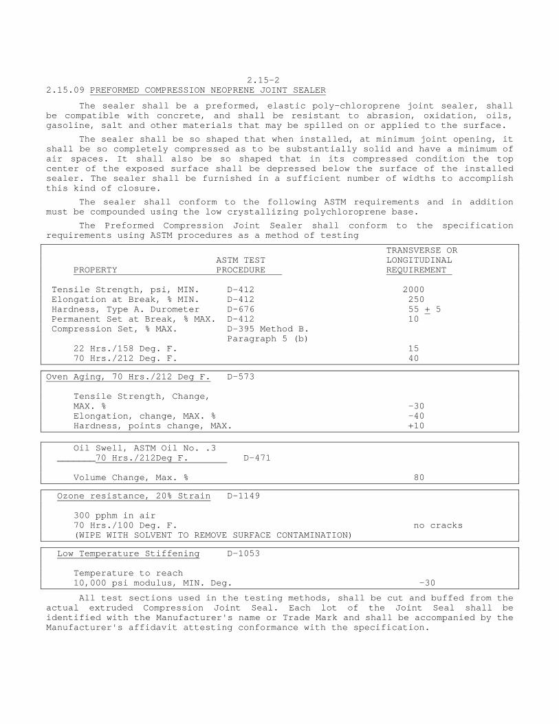
2.15.09 PREFORMED COMPRESSION NEOPRENE JOINT SEALER
The sealer shall be a preformed, elastic poly-chloroprene joint sealer, shall be compatible with concrete, and shall be resistant to abrasion, oxidation, oils, gasoline, salt and other materials that may be spilled on or applied to the surface.
The sealer shall be so shaped that when installed, at minimum joint opening, it shall be so completely compressed as to be substantially solid and have a minimum of air spaces. It shall also be so shaped that in its compressed condition the top center of the exposed surface shall be depressed below the surface of the installed sealer. The sealer shall be furnished in a sufficient number of widths to accomplish this kind of closure.
The sealer shall conform to the following ASTM requirements and in addition must be compounded using the low crystallizing polychloroprene base.
The Preformed Compression Joint Sealer shall conform to the specification requirements using ASTM procedures as a method of testing
TRANSVERSE OR ASTM TEST LONGITUDINAL PROPERTY PROCEDURE REQUIREMENT Tensile Strength, psi, MIN. D-412 2000 Elongation at Break, % MIN. D-412 250 Hardness, Type A. Durometer D-676 55 + 5 Permanent Set at Break, % MAX. D-412 10 Compression Set, % MAX. D-395 Method B. Paragraph 5 (b) 22 Hrs./158 Deg. F. 15 70 Hrs./212 Deg. F. 40 Oven Aging, 70 Hrs./212 Deg F. D-573 Tensile Strength, Change, MAX. % -30 Elongation, change, MAX. % -40 Hardness, points change, MAX. +10 Oil Swell, ASTM Oil No. .3 _______70 Hrs./212Deg F. D-471 Volume Change, Max. % 80 Ozone resistance, 20% Strain D-1149 300 pphm in air 70 Hrs./100 Deg. F. no cracks (WIPE WITH SOLVENT TO REMOVE SURFACE CONTAMINATION)
Low Temperature Stiffening D-1053 Temperature to reach 10,000 psi modulus, MIN. Deg. -30
All test sections used in the testing methods, shall be cut and buffed from the actual extruded Compression Joint Seal. Each lot of the Joint Seal shall be identified with the Manufacturer's name or Trade Mark and shall be accompanied by the Manufacturer's affidavit attesting conformance with the specification.
2.15-3
The sealer shall be that manufactured by Acme Highway Products Corp., 33 Chandler Street, Buffalo, New York, and shall be Type S-497 for Item 22 (a) and Type S-502 for Item 22 (b) or an approved equal.
The lubricant-adhesive shall be a one component polychloroprene compound containing only soluble phoenolic resins blended together with anti-oxidants and acid acceptors in an aromatic hydrocarbon solvent mixture and shall have the following physical properties:
Average net weight per gallon - 7.84 lbs. + 5% Solids Content - 24 - 26% by weight Brookfield Viscosity @ 77 Deg. F., #2 Spindle at 10 RPM
-7,000 - 7,500 cps
The adhesive shall remain fluid from 5 Deg F. to 120 Deg. F. Film strength (ASTM-D-412) - 2,300 minimum tensile strength, 750% minimum elongation before breaking.
Test specimens composed of 2 pieces of 0.064 gauge 6061 Aluminum alloy bonded together with the adhesive on a joint 1" wide with 1/2" lap and aged 14 days shall show the following minimum strength when tested by the laboratory:
Dynamic Strength 1,300 psi @ 70 Deg. F. 1,300 psi @ 0 Deg. F.
Static (1 minute) 700 psi @ 70 Deg. F. 700 psi @ 0 Deg. F.
Each lot of the adhesive shall be delivered in Containers plainly marked with the Manufacturer's Name or TradeMark and date of manufacture and shall be accompanied by the Manufacturer's affidavit attesting conformance with this specification.
The lubricant-adhesive shall be "Acme Neo-Lube" as manufactured by Acme Highway Products Corp. or approved equal.
Inspection of Material: All sealers and adhesives will be furnished to comply with the material as approved as a result of tests. For all such sealer and adhesive furnished and installed on a contract, the contractor shall furnish to the Engineer a certification that the materials placed are the same as those approved and shall back this up with a certification by the Manufacturer as to the nature and characteristics of the materials purchased by the Contractor. The exact details of the certification will be furnished at the time the material under test is approved.
Preformed compression neoprene joint sealer shall be used only where specifically called for in the specifications, contract plans, or by the Engineer.
2.15.10 JOINT SEALER BOND BREAKER
The bond breaker shall be an approved transparent tape of a color which contrasts with the surface to which it is applied or an approved masking tape, equal to "Scotch Brand", as manufactured by he Minnesota Mining and Manufacturing Company, St. Paul, Minnesota. The tape shall be non-bituminous and of the size shown on the contract plans.
Bond breaker shall be used only where specifically called for in the specifications, contract plans or by the Engineer. 2.15.11 JOINT DAMMING MATERIAL
Damming material shall be an inert material meeting the approval of the Engineer. Paper rope, or other material, which will decompose, will not be approved.
Damming material shall be used only when ordered by the Engineer, shown on the plans or required by the Special Conditions.

2.15-4
SECTION 2.16 REINFORCED CONCRETE PIPE
2.16.1 These specifications cover reinforced concrete pipe intended to be used for the conveyance of sewage, industrial wastes, and storm water, and for the construction of culverts. ESCRIPTIOND This pipe shall consist of concrete and reinforcement conforming to the requirements of A.S.T.M. Specification C-76-63T, as amended to date or A.S.T.M. Specification C-507-63T, as amended to date, whichever is applicable or as amended by these specifications.
When the pipe is to be used for sanitary or industrial waste lines or when specified on the drawings, it shall have an inside coating in accordance with Section 30.02 of these Specifications.
The pipes shall be manufactured in 4-foot minimum lengths.
Pipe shall not be shipped for use until it has been approved as complying with these requirements and not until it is at least 14 days old. 2.16.2 INSPECTION AND REJECTION OF PIPE Preliminary to any Contractor placing an order, the City Engineer shall be entitled to test not more than ten pieces of pipe covering the sizes in which it is interested. The test specimens shall be selected in approximately equal numbers from the larger and smaller sizes of pipe. The acceptability of the large sizes of pipe shall not be based on the results of tests in smaller sizes. After these preliminary tests the City Engineer shall be entitled to additional tests in such numbers and at such times as it may deem necessary, provided, that the total number of pipes tested shall not equal 2 percent of the total deliveries.
2.16.3 Acceptance of the pipe shall be made on the basis of plant load bearing tests, material, tests and inspection of the completed product, as specified in Section 3, paragraph 1, of A.S.T.M. Specifications C76-59T, with additions and exceptions as follows:
1. Pipe shall be tested by the three-edge bearing method, if required.
2. The pipe shall be subject to thorough inspection and tests, the right being reserved for the Engineer to apply such of the tests specified as may from time to time be deemed necessary.
3. All pipe will be inspected upon delivery, and such as does not conform to the requirements of this contract shall be rejected and must be immediately removed by the Contractor, who shall furnish all labor necessary to assist the inspector in inspecting the material.
4. If required, the Contractor shall furnish two pipes of the type and size to be used as ordered, with all other necessary materials and equipment, and shall make pressure demonstration tests in the presence of the Engineer to show that the pipes, when laid together with proposed joint are capable of withstanding a hydrostatic pressure of 15 psi. which pressure shall be maintained for at least 30 minutes without visible leakage. Moisture appearing on the surface of the pipe in form of patches or beads adhering to the surface shall not be considered leakage.
Thirty minutes after the pipe and joint have successfully met the above test and while the test pipe is still under the internal pressure, the joint shall be deflected so that one side is open at least 3/4" from its original position without leakage.
5. The quality of all materials, the process of manufacture, and the finished pipe shall be subject to the inspection and approval by the Engineer. Such inspection may be made at the place of manufacture or on the work after delivery, or at both places, and the pipe shall be subject to rejection at any time on account of failure to meet any of the specification requirements, even though sample pipe may have been accepted as satisfactory.
The Engineer shall also have the right to take samples of the concrete, after it has been mixed or as it is being placed in the forms or molds, and to make such inspection and tests thereof as he may wish.
6. All pipe which has been damaged after delivery will be rejected, and if such pipe has already been laid in the conduit line it shall be acceptably repaired, if permitted, or removed and replaced or made good, solely at the Contractor's expense.
7. At the time of inspection, the pipe surfaces shall be dense and close-textured. Cores shall serve as a basis for rejection of pipe if poor bond or reinforcement is exposed. Unsatisfactory pipe will be permanently rejected. Only those pipes actually conforming to the specifications and accepted will be listed for approval, shipment and payment.
8. No separate payment shall be made for any costs incurred due to inspection of pipe and such costs incurred shall be included in all the unit contract prices.
2-55
SECTION 2.19 CAST IRON PIPE
2.19.1 This section describes bell and spigot cast iron pipe and flexible joint cast iron
pipe, including fittings and special castings, for sewers and appurtenances.
2
.19.2 A. Cast iron pipe and fittings shall be of the following classes:
BELL AND SPIGOT PIPE CLASS OF FITTING Class Size __________________________________________________________________________________________________________________________________________________________________________________
50,100, and 150 4" to 12", incl. D 50 and 100 14" to 24", incl. B 150 14" to 24", incl. D 50 30" to 60", incl. A 100 30" to 60", incl. B 150 30" to 60", incl. C
Class 100 - Flexible Joint Pipe (Metropolitan Type)
B. Class 50 shall be used unless otherwise specified.
2.19.3 A. Cast iron pipe shall be of the sizes shown in the Reference Specifications.
B. Size of pipe and fittings shall be as specified.
C. Special castings shall be of the sizes and dimensions as shown, specified or required.
2.19.4 A. Every pipe and fitting shall have distinctly cast upon it the initials of the maker's name for identification.
B. The weight and class letter shall be conspicuously painted by the manufacturer with white oil paint on the inside of each pipe and fitting after the coating has become hard.
2.19.5 A. Pipe, fittings and special castings shall be made of cast iron of good quality, and of such character as shall make the metal of the castings strong, tough and of even grain and soft enough to satisfactorily admit of drilling and cutting. The metal shall be made without any admixture of cinder iron or other inferior metal, and shall be remelted in a cupola or air furnace. B. Pipe, fittings and special castings shall be smooth, free from scale, lumps, blisters, sand holes and defects of every nature which unfit them for the use for which they are intended. No plugging or filling will be allowed.
2.19.6 A. Pipe shall comply with the requirements of the latest Standard Specifications of the American Standards Associations for Cast Iron Pit Cast Pipe, Designation A21.2 or for Cast Iron Centrifugally Cast Pipe Designations A21.6 and A21.8.
Fittings shall comply with the requirements of the latest Standard Specifications of the American Water Works Association for Cast Iron Fittings, Designation C 100-08.
B. Dimensions, weight and allowable variations of pipe and fittings shall be in accordance with the Reference Specifications.
C. Special castings shall comply with the requirements stipulated herein for pipe and fittings.
2.19.7 All underground pipe and fittings shall be given an exterior coating of coal tar pitch varnish in accordance with Federal Specifications Designation WW-P-421.
All pipe and fittings shall be given an upside cement mortar lining with a seal coat inside, as per the latest ASA Standard A21.4.
2.19-1
SECTION 2.20 JOINT MATERIALS FOR PIPE
2.20.1 This section describes materials for jointing vitrified clay pipe, reinforced concrete pipe, and cast iron pipe. 2.20.2 A. Joints shall be of the following types: Type 1 - Gasket and Mortar Joint Type 2 - Poured Bituminous Compound Joint Type 3 - premolded Bituminous Compound Joint Type 4 - Lead Joint Type 5 - "O" Ring Rubber Gasket and Mortar Joint B. Type shall be as specified. 2.20.3 A. Type 1 - Gasket and Mortar Joint shall consist of a caulked jute or oakum gasket and a cement mortar packing. B. Type 2 - Poured Bituminous Compound Joint shall consist of a caulked jute or oakum gasket and poured bituminous compound filler. C. Type 3 -premolded Bituminous Compound Joint shall consist of collars of bituminous compound cast in the bell and on the spigot ends of the pipe. Immediately prior to joining the pipes, the collars shall be suitably treated. D. Type 4 - Lead Joint shall consist of a packed jute gasket and caulked soft lead. E. Type 5 - "O" Ring Rubber Gasket and Mortar Joint shall consist of an approved rubber gasket and a cement mortar packing. "O" Ring Rubber Gasket shall be made of rubber of composition having a texture to assure a watertight and permanent seal and shall be the product of a manufacturer having at least five years experience in the manufacture of rubber gaskets for pipe joints. The gasket shall be a continuous ring, of suitable cross-section and of such size as to make the joint watertight when the pipes are laid. The rubber shall have a reasonably smooth surface free from pitting, blisters, porosity and other imperfections. Rubber for the gasket shall meet the following physical requirements. The basic polymer shall be natural rubber, neoprene, or other synthetic rubbers, or a blend of both, acceptable to the Engineer. The tensile strength of the compound shall be at least 1200 psi and shall be determined in accordance with A.S.T.M. Designation D142. The elongation at rupture shall be such that 2" gage marks shall stretch to not less than 9 inches and shall be in accordance with A.S.T.M. Designation D412. The compression set shall not exceed 25% and shall be determined in accordance with A.S.T.M. Designation D395, Method B (constant deflection). The tensile strength of the compound after being subjected to an accelerated aging test for 96 hours in air at 158 Deg. F. shall not be less than 80% of the tensile strength before aging and shall be determined in accordance with A.S.T.M. Designation D573. The water absorption by weight after 48 hours at 70 Deg. C shall not exceed 5 percent.
11152242.20-1
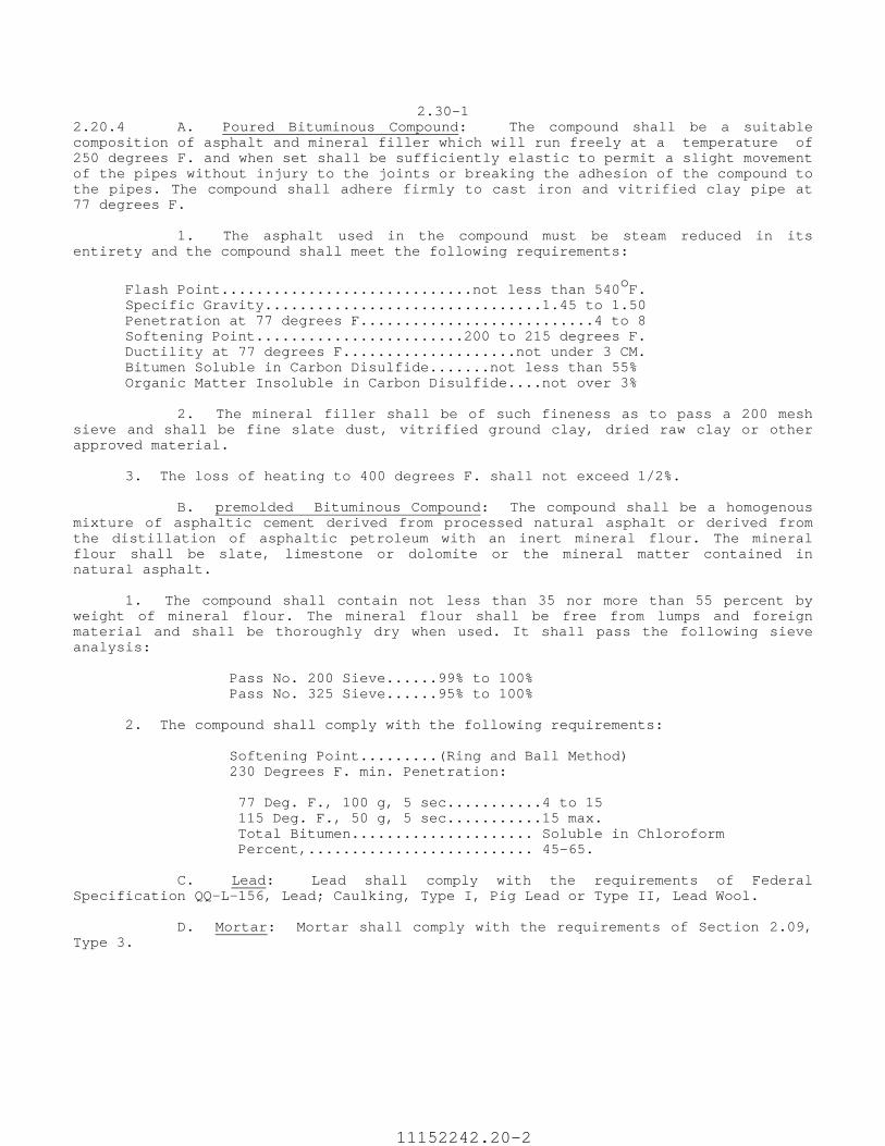
2.30-1 2.20.4 A. Poured Bituminous Compound: The compound shall be a suitable composition of asphalt and mineral filler which will run freely at a temperature of 250 degrees F. and when set shall be sufficiently elastic to permit a slight movement of the pipes without injury to the joints or breaking the adhesion of the compound to the pipes. The compound shall adhere firmly to cast iron and vitrified clay pipe at 77 degrees F. 1. The asphalt used in the compound must be steam reduced in its entirety and the compound shall meet the following requirements:
Flash Point.............................not less than 540oF. Specific Gravity................................1.45 to 1.50 Penetration at 77 degrees F...........................4 to 8 Softening Point........................200 to 215 degrees F. Ductility at 77 degrees F....................not under 3 CM. Bitumen Soluble in Carbon Disulfide.......not less than 55% Organic Matter Insoluble in Carbon Disulfide....not over 3% 2. The mineral filler shall be of such fineness as to pass a 200 mesh sieve and shall be fine slate dust, vitrified ground clay, dried raw clay or other approved material. 3. The loss of heating to 400 degrees F. shall not exceed 1/2%. B. premolded Bituminous Compound: The compound shall be a homogenous mixture of asphaltic cement derived from processed natural asphalt or derived from the distillation of asphaltic petroleum with an inert mineral flour. The mineral flour shall be slate, limestone or dolomite or the mineral matter contained in natural asphalt. 1. The compound shall contain not less than 35 nor more than 55 percent by weight of mineral flour. The mineral flour shall be free from lumps and foreign material and shall be thoroughly dry when used. It shall pass the following sieve analysis: Pass No. 200 Sieve......99% to 100% Pass No. 325 Sieve......95% to 100% 2. The compound shall comply with the following requirements: Softening Point.........(Ring and Ball Method) 230 Degrees F. min. Penetration: 77 Deg. F., 100 g, 5 sec...........4 to 15 115 Deg. F., 50 g, 5 sec...........15 max. Total Bitumen..................... Soluble in Chloroform Percent,.......................... 45-65. C. Lead: Lead shall comply with the requirements of Federal Specification QQ-L-156, Lead; Caulking, Type I, Pig Lead or Type II, Lead Wool. D. Mortar: Mortar shall comply with the requirements of Section 2.09, Type 3.
11152242.20-2

2.30-02
11152242.20-3
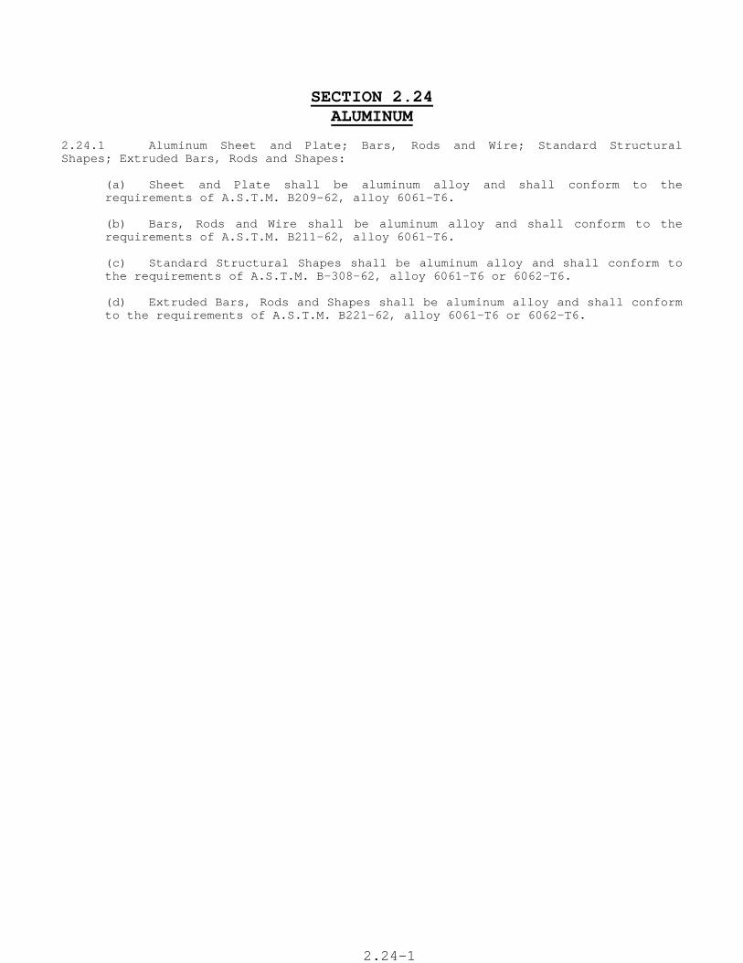
SECTION 2.24 ALUMINUM
2.24.1 Aluminum Sheet and Plate; Bars, Rods and Wire; Standard Structural Shapes; Extruded Bars, Rods and Shapes: (a) Sheet and Plate shall be aluminum alloy and shall conform to the
requirements of A.S.T.M. B209-62, alloy 6061-T6. (b) Bars, Rods and Wire shall be aluminum alloy and shall conform to the
requirements of A.S.T.M. B211-62, alloy 6061-T6. (c) Standard Structural Shapes shall be aluminum alloy and shall conform to
the requirements of A.S.T.M. B-308-62, alloy 6061-T6 or 6062-T6. (d) Extruded Bars, Rods and Shapes shall be aluminum alloy and shall conform
to the requirements of A.S.T.M. B221-62, alloy 6061-T6 or 6062-T6.
2.24-1
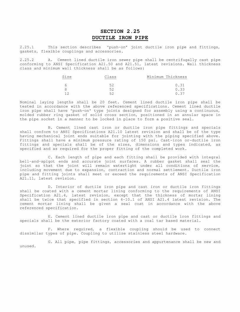
SECTION 2.25 DUCTILE IRON PIPE
2.25.1 This section describes "push-on” joint ductile iron pipe and fittings, gaskets, flexible couplings and accessories. 2.25.2 A. Cement lined ductile iron sewer pipe shall be centrifugally cast pipe conforming to ANSI Specification A21.50 and A21.51, latest revisions. Wall thickness class and minimum wall thickness shall be as follows: Size Class Minimum Thickness 6 52 0.31 8 52 0.33 12 52 0.37 Nominal laying lengths shall be 20 feet. Cement lined ductile iron pipe shall be tested in accordance with the above referenced specifications. Cement lined ductile iron pipe shall have "push-on" type joints designed for assembly using a continuous, molded rubber ring gasket of solid cross section, positioned in an annular space in the pipe socket in a manner to be locked in place to form a positive seal. B. Cement lined cast iron or ductile iron pipe fittings and specials shall conform to ANSI Specifications A21.10 latest revision and shall be of the type having mechanical joint ends suitable for jointing with the piping specified above. Fittings shall have a minimum pressure rating of 150 psi. Cast-iron or-ductile iron fittings and specials shall be of the sizes, dimensions and types indicated, as specified and as required for the proper fitting of the completed work. C. Each length of pipe and each fitting shall be provided with integral bell-and-spigot ends and accurate joint surfaces. A rubber gasket shall seal the joint so that the joint will remain watertight under all conditions of service, including movement due to expansion, contraction and normal settlement. Ductile iron pipe and fitting joints shall meet or exceed the requirements of ANSI Specification A21.11, latest revision. D. Interior of ductile iron pipe and cast iron or ductile iron fittings shall be coated with a cement mortar lining conforming to the requirements of ANSI Specification A21.4, latest revision, except that the thickness of mortar lining shall be twice that specified in section 4-10.1 of ANSI A21.4 latest revision. The cement mortar lining shall be given a seal coat in accordance with the above referenced specification. E. Cement lined ductile iron pipe and cast or ductile iron fittings and specials shall be the exterior factory coated with a coal tar based material. F. Where required, a flexible coupling should be used to connect dissimilar types of pipe. Coupling to utilize stainless steel hardware. G. All pipe, pipe fittings, accessories and appurtenance shall be new and unused.

2-71
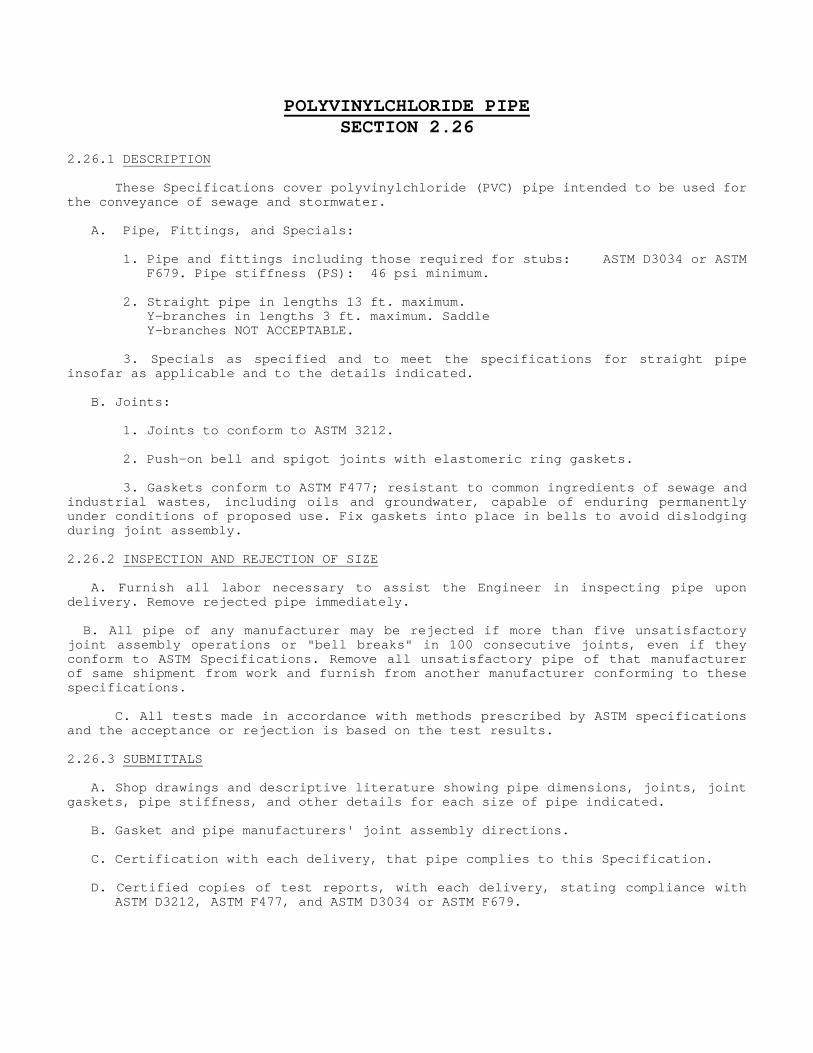
POLYVINYLCHLORIDE PIPESECTION 2.26
2.26.1 DESCRIPTION
These Specifications cover polyvinylchloride (PVC) pipe intended to be used for the conveyance of sewage and stormwater. A. Pipe, Fittings, and Specials: 1. Pipe and fittings including those required for stubs: ASTM D3034 or ASTM F679. Pipe stiffness (PS): 46 psi minimum. 2. Straight pipe in lengths 13 ft. maximum. Y-branches in lengths 3 ft. maximum. Saddle Y-branches NOT ACCEPTABLE. 3. Specials as specified and to meet the specifications for straight pipe insofar as applicable and to the details indicated. B. Joints: 1. Joints to conform to ASTM 3212. 2. Push-on bell and spigot joints with elastomeric ring gaskets. 3. Gaskets conform to ASTM F477; resistant to common ingredients of sewage and industrial wastes, including oils and groundwater, capable of enduring permanently under conditions of proposed use. Fix gaskets into place in bells to avoid dislodging during joint assembly. 2.26.2 INSPECTION AND REJECTION OF SIZE A. Furnish all labor necessary to assist the Engineer in inspecting pipe upon delivery. Remove rejected pipe immediately. B. All pipe of any manufacturer may be rejected if more than five unsatisfactory joint assembly operations or "bell breaks" in 100 consecutive joints, even if they conform to ASTM Specifications. Remove all unsatisfactory pipe of that manufacturer of same shipment from work and furnish from another manufacturer conforming to these specifications. C. All tests made in accordance with methods prescribed by ASTM specifications and the acceptance or rejection is based on the test results. 2.26.3 SUBMITTALS A. Shop drawings and descriptive literature showing pipe dimensions, joints, joint gaskets, pipe stiffness, and other details for each size of pipe indicated. B. Gasket and pipe manufacturers' joint assembly directions. C. Certification with each delivery, that pipe complies to this Specification. D. Certified copies of test reports, with each delivery, stating compliance with ASTM D3212, ASTM F477, and ASTM D3034 or ASTM F679.

2.26-01
SECTION 10.01 TRAFFIC AND CONSTRUCTION
10.01.1 DESCRIPTION (A) The Contractor shall keep all existing streets and sidewalks open to vehicular and pedestrian traffic for the full length and duration of the project and shall provide a sufficient number of travel lanes and pedestrian passways to accommodate traffic ordinarily using the street and sidewalks. The Contractor shall maintain and protect traffic in accordance with the current edition of "The Manual on Uniform Traffic Control Devices (MUTCD), Part VI", a copy of which is on file with the City of New Haven Department of Traffic and Parking, and hereby made a part of these contract specifications. The portions of streets over which traffic is maintained shall be kept in such condition that traffic will be safely and adequately accommodated. Sidewalks are to be kept free of excavated materials, tool, machinery and other subjects that will impede or endanger pedestrian traffic. Suitable ingress and egress provisions shall be made for abutting owners and tenants at all times. (B) The Contractor shall furnish, erect, light and maintain such signs, barricades, barrels, flashers and warning lights as needed or directed by the Engineer, for the regulation and protection of traffic and pedestrians. Such signs, barricades, barrels, flashers, and warning lights shall be used to safely and adequately keep pedestrians, including handicapped persons, and vehicles from equipment, materials, obstacles, excavations, and newly constructed structures. Flagmen shall be provided for the regulation and protection of traffic or pedestrians, as needed or directed. (C) No separate payment will be made for traffic signs, barricades, barrels, flashers, warning lights, flagmen, etc. and all costs in connection therewith shall be included in the contract lump sum item "Maintenance and Protection of Traffic." 10.10.01.2 MATERIALS All signs, barricades, barrels, flashers, warning lights used for the maintenance and protection of traffic shall conform to the standards of the American Traffic Safety Services Association. 10.01.3 CONSTRUCTION METHODS Not applicable. 10.01.4 METHOD OF MEASUREMENT This item will not be measured for payment. 10.01.5 BASIS OF PAYMENT This work will be paid for at the contract lump sum price for "Maintenance and Protection of traffic". This price shall include the cost of all flagmen, signs, barricades, barrels, flashers, warning lights, and all flashing signs, etc., and all materials, labor and equipment necessary for the maintenance and protection of traffic as specified herein. Payment for trafficmen required by the City will be made under "Trafficmen" as specified in Section 10.02 of these Technical Specifications.

10.01-1
SECTION 10.02 TRAFFICMEN
10.02.1 DESCRIPTION The Contractor shall furnish uniformed policemen to act as trafficmen at all locations that the proper officials may deem necessary. The trafficmen will be assigned in conformance with the requirements of the "Standard for Control and Protection of Traffic on Construction and Maintenance Projects Within the Public Right of Way," City of New Haven, 1962; on file in the Department of Traffic and Parking and herein made part of these contract specifications, except as otherwise stipulated below or as directed by the Engineer. 10.02.2 MATERIALS Not applicable. 10.02.3 CONSTRUCTION METHODS Not applicable. 10.02.4 METHOD OF MEASUREMENT This item will not be measured separately for payment. 10.02.5 BASIS OF PAYMENT This item of work will not be paid for separately. This item shall be included in the unit price per ton of bituminous concrete installed and accepted.
10-02-1
SECTION 20.01 REMOVAL OF PAVEMENT
20.01.1 DESCRIPTION Pavement removal shall consist of the satisfactory removal of pavements designated on the plans to be completely or partly removed, except pavement removed which falls within the limits of "Unclassified Excavation". It shall include asphalt, concrete pavements and bases as required by the contract or as directed by the Engineer. 20.01.2 MATERIALS NOT APPLICABLE 20.01.3 CONSTRUCTION METHODS Pavement shall be cut to neat lines as required by the contract drawings, or as directed by the Engineer. Concrete pavement shall be cut with a concrete saw. Pavement shall be excavated to the dimension shown on the plan. Excavated material shall be disposed of as directed by the Engineer and in the same manner as described for surplus material in the section on "Unclassified Excavation" of these specifications. No sections or pieces of pavement shall be used in trench backfill and pavement shall be kept separate from other excavated material. 20.01.4 METHOD OF MEASUREMENT Measurement shall be made by the Engineer and shall be the area in square yards regardless of depth. The area to be measured shall be the actual length times the width as shown on the drawings, within the pay limits as shown on the plans. Pavement removal, which is within the limits of “Unclassified Excavation”, shall not be included. 20.01.5 BASIS OF PAYMENT Payment for the removal of pavements will be made at the contract unit price per square yard for "Removal of Pavement" which price shall include all equipment, tools and labor necessary for the removal and satisfactory disposal of all pavements.

20-01-1
SECTION 20.02 TRENCH EXCAVATION AND BACKFILL
20.02.1 DESCRIPTION
Trench excavation shall consist of the removal and disposal of all materials, including water, and backfilling necessary for construction of sewers and appurtenance, to the dimensions shown on the plans or as directed by the Engineer, all in accordance with these specifications for the following:
1. The construction of sanitary sewers storms sewers, endwalls, underdrains, and service laterals.
2. The removal of underground drainage structures and appurtenances not to be replaced.
3. The removal of miscellaneous items such as abandoned underground tanks, pipe lines, etc.
20.02.2 Trench Excavation in Rock - Rock, as it applies to trench excavation shall be defined as rock in definite ledge formation, boulders, portions of boulders, cement masonry structures, or concrete structures, of 1/2 cubic yard or more in volume, removed as indicated or directed from within the payment lines for trench excavation. Material, which can be removed by normal excavation methods, will not be paid for as rock.
20.02.3 CONSTRUCTION METHODS
1. Excavation
Trench excavation shall be made in conformity with the requirements of the plans or as ordered. The Contractor shall furnish and employ such shores, braces, sheeting, pumps, etc., as may be necessary for the proper completion of work, the protection of property, the safety of the public and employees of the Contractor. All safety precautions shall conform to Section 5 of the State of Connecticut Labor Department Construction Safety Code latest edition and the U.S. Department of Labor Occupational Safety and Health Regulations, Title 29, Chapter XVII, paragraph 1926.651 Specific Excavation Requirements and paragraph 1926.652 Specific Trenching Requirements.
The Contractor shall notify the Engineer after the excavation is completed. No masonry, pipe or other material shall be placed in the excavated area until the Engineer has approved the depth of excavation and the character of the foundation material.
The length of the trench opened at one time shall not exceed 200 feet or such length, as the Engineer considers reasonable and necessary. Blasting operations shall be conducted in strict accordance with the City and State ordinances and regulations. The handling of explosives and methods of blasting shall conform to the requirements specified elsewhere in these specifications.
When, in the opinion of the Engineer, the safety of water mains, sewers and other structures would be endangered by blasting, the Contractor shall remove the rock by approved methods other than blasting. All rock as defined above, removed in this manner shall be measured for payment as rock excavation.
Whenever a stub for a proposed sewer or extension of a sewer is built in rock, the rock shall be excavated not less than 5 feet beyond the end of the pipe.
The Contractor shall at all times keep the excavation free from water. The water shall be disposed of as specified elsewhere in these specifications.
The Engineer may require that the last six inches of trench excavation be removed by hand excavation.
Where the soil in the trench is found to be soft or loose or in any way unsuitable, the Engineer may order it removed and replaced with "Broken Stone Fill" or "Gravel Fill". No payment will be made for "Broken Stone Fill" or "Gravel Fill" which the Contractor may install to facilitate dewatering of the trench.
Sheeting and Bracing
A. Where shown on the plans, specified, or required, excavation shall be supported by adequate sheeting and bracing driven ahead of the excavation. See first paragraph of this edition.
B. The Contractor will be held accountable and responsible for the sufficiency of all sheeting and bracing used.
20.02-01
C. Where the materials to be excavated is of such character as to render it necessary, the sheeting shall be tongued and grooved and driven to such depths as may be directed.
D. Where the nature of the material encountered or the safety of the adjacent structures render it necessary, the Contractor may resort to the use of sheet metal piling with prestressed bracing, or he may underpin the structures or buildings. Approval of sheeting shall in no manner affect the obligation of the Contractor with respect to such building or structures.
D. Where the nature of the material encountered or the safety of the adjacent structures render it necessary, the Contractor may resort to the use of sheet metal piling with prestressed bracing, or he may underpin the structures or buildings. Approval of sheeting shall in no manner affect the obligation of the Contractor with respect to such building or structures.
Below the street surface, or legal grade, whichever is lower.
F. All rangers and braces (except those in the way of the structure) shall be left in place when the sheeting is ordered to be left in place.
2. Backfilling
Coarse sand, fine gravel or any similar material suitable to the Engineer shall be used to fill around the pipe. Filling on both sides of pipe and up to a depth of 12" over the top of pipe shall be placed carefully by hand in layers, 4" to 6" thick, and each layer will be tamped and compacted before the next layer is placed. Care must be taken that the fill is made compact and tight under the lower half of the pipe. Remaining backfill shall be placed in layers of not more than 6 inches in depth after compaction and shall be thoroughly compacted by means of mechanical rammers or vibrators or by pneumatic tampers. Hand tampers shall be used only around the pipe. All voids along sides of trench, behind sheeting, under bracing of other objects, shall be completely and carefully filled tight, using such fine materials, hand labor and tools as may be necessary.
Fill material shall not be allowed to fall through a height of over five feet until the sewer has been well covered, nor within five feet of any vertical wall of any manhole, chimney or similar structure. The material used shall be of a quality satisfactory to the Engineer and shall be free from large or frozen lumps, wood and other extraneous material.
All suitable material removed in making the excavation shall be used for backfill. Any surplus or unsuitable material not required or permitted to be used for backfilling shall be removed from the limits of the work and deposited at such point or points as the Engineer may direct on other property owned by the City of New Haven. Material shall be deposited and spread uniformly as directed by the Engineer, within the limits of the area designated by him to receive the surplus material.
Where, in the opinion of the Engineer, excavated material is unsuitable for backfilling, the Contractor shall furnish and place suitable material as specified at no additional cost to the City.
Backfilling in public streets and highways shall be done in accordance with the rules, regulations, laws and ordinances of the City of New Haven or the State of Connecticut depending upon which governmental unit is responsible for the maintenance of said streets or highways. It is the responsibility of the bidders and contractors to ascertain and comply with these requirements.
Water shall be used to obtain the required compaction only when specifically directed or approved by the Engineer. If the trench has been excavated in sand, gravel or other pervious material, the Engineer may, at his option, permit the use of water to compact fill. Water shall not be used to compact backfill in any trench in impervious material such as clay.
The site of the work will be cleaned of all rubbish and surplus materials and promptly put into good order comparable to conditions prior to the start of the contract as backfilling proceeds and work progress along the line. Pavements adjacent to the site of the work shall be constantly swept as to prevent scarring of the pavement by scattered stones.
No separate payment will be made for clean up.
20.02.4 METHOD OF MEASUREMENT
Except, as noted below, trench excavation will be measured in its original position by taking the difference between the ground surface at the time the trench is excavated and that after excavation, the Contractor shall notify the Engineer, so that elevations and measurements of the work may be obtained. Any work done prior to such notification will not be paid for.
Payment limits shall be as described hereinafter.
20.02-02
HORIZONTAL PAYMENT LIMITS:
Payment lines shall be vertical for pipe arches, sewers, service laterals and underdrains and shall be the width to which the material is actually removed except that in no case shall the width between payment lines be more than the following:
HORIZONTAL PAYMENT LIMITS:
Payment lines shall be vertical for pipe arches, sewers, service laterals and underdrains and shall be the width to which the material is actually removed except that in no case shall the width between payment lines be more than the following:
a. For pipe-arches, sewers, service laterals and underdrains, 2 feet greater than the nominal horizontal inside dimension of pipe where such dimension is less than 36 inches.
b. For the same types of pipe-arches 3 feet greater than nominal horizontal inside dimensions of the pipe where such dimension is 36 inches or greater.
c. For endwalls, payment lines shall be vertical and 2 feet outside of the neat lines of the foundations in each direction horizontally.
d. At manholes or catch basins the face or end of the pipe in the manhole or catch basin or the inside face of the structure whichever is less.
e. Payment lines for rock excavation at manholes and catch basins shall be 2 feet outside the neat lines of the manhole or catch basin, with above deducted.
In case it is necessary to excavate to a greater width than that specified above on account of the removal of existing structures, such additional excavation will be considered as trench excavation and will be measured and paid for as such.
For the removal of underground obstructions such as pipe lines, tanks, etc., maximum payment lines shall be vertical and 2 feet outside of the underground item measure horizontally.
If rock is encountered, the Contractor shall strip it of sufficient overlay material to allow for proper measurement and shall then notify the Engineer that the rock surface is ready for measurement. If the Contractor shall fail to give such notice, the Engineer shall presume that the measurements taken at the time he first saw the material in question will give the true quantity of excavation.
VERTICAL PAYMENT LIMITS:
Payment lines will extend vertically from the bottom of the pipe or accepted trench to the bottom of the new base course, in the case of new or reconstructed roadways, to the bottom of the existing pavement base in the case of existing roadways not to be reconstructed; or to existing ground in cases where there is no paved roadway; whichever is applicable.
20.02.5 BASIS OF PAYMENT
This work will be paid for at the contract unit price per cubic yard for "Trench Excavation 0' to 12' Deep" or "Trench Excavation 0' to over 12' Deep" as the case may be.
When rock, conforming to the description given in Section 20.2.1 is encountered within the payment lines for trench excavation, its removal will be classified and paid for at the contract unit price per cubic yard for "Trench Excavation in Rock 0' to 12' Deep" or Trench Excavation in Rock 0' to over 12' Deep" as the case may be.
These portions of trench excavation classified and paid for as "Trench Excavation in Rock" of the various depths will be the actual volumes of rock excavated within the payment lines at the applying bottom depth price. These portions of trench excavation above the rock will be the actual volume of trench excavation above the rock will be the actual volume of earth excavated within the payment lines at the applying bottom depth of rock.
The above prices shall include all materials, tools, equipment, labor and incidental work necessary to complete the excavation in conformity with the plans or as ordered. They shall also include backfilling, replacement or unsuitable backfill material, and disposal of surplus or unsuitable material at locations directed by the Engineer. No additional payment will be made foe shoring, bracing, sheeting, pumping, bailing or water removal necessary for satisfactory completion of the work.
If "Broken Stone Fill" or "Gravel Fill" are used to replace unsuitable material below the bottom of the pipe bedding at the direction of the Engineer, payment will be made at their respective contract unit prices. Payment will not be allowed where the Contractor has removed extra material below the pipe bottom for his own convenience or in error, but such material shall be replaced in a manner satisfactory to the Engineer at no extra cost to the City. See Section 20.2.3
20.02-03
SECTION 20.03 TEST PITS
20.03.1 DESCRIPTION It may be necessary for the Engineer or Contractor to locate or examine soils, ground water, drains, pipes, rocks, public utilities, or any other obstacles. This work shall consist of the satisfactory removal of all materials, including water, within the limits of the test pit. This work shall also include the satisfactory stockpiling, disposal of surplus or unsuitable material, and backfilling with suitable material as approved by the Engineer. This work shall be done where shown on the Contract Drawings or where directed by the Engineer. 20.03.2 NOT APPLICABLE 20.03.3 CONSTRUCTION METHODS Test pit excavations shall have neat, clean cut and vertical sides. Upon completion of the test pit, the Engineer shall be notified so that he shall make the necessary measurements to locate all objects within the test pit. 1. Excavation - All excavation for test pits shall be done by hand digging,
unless otherwise directed by the Engineer. 2. Backfilling - The backfilling of test pits shall be in accordance with
the requirements for backfilling trenches as provided in Section 20.2.3 of these specifications.
20.03.4 METHOD OF MEASUREMENT The Engineer will measure excavation for test pits for payment, and shall the Engineer order the actual length, width and depth of the excavation within the limits. 20.03.5 BASIS OF PAYMENT Payment for "Test Pits" shall be made at the contract unit price, per cubic yard, for "Test Pits", which price shall include the excavation of all materials, all labor and equipment incidental to the excavating, backfilling and restoration of pavement of the "Test Pit".

20.03-1
SECTION 20.04 EXCAVATION AND BACKFILL FOR STRUCTURES
20.04.1 DESCRIPTION
This work shall consist of the removal and disposal of all materials necessary for the construction of structure, including backfilling, compacting the backfill, disposing of surplus material, and cleaning up the site. This work shall include all necessary clearing, grubbing and removing old structures or parts thereof, as required, except where the contract includes a separate item or items for such work.
20.04.2 NOT APPLICABLE
20.04.3 CONSTRUCTION METHODS
1. Earth Excavation
Foundation excavation shall be made of sufficient size to permit construction of the foundation units and to provide for adequate drainage. When masonry is to rest on an excavated surface other than rock, special care shall be taken not to disturb the bottom of the excavation. To accomplish this, the Engineer may require that no earth shall be excavated by machinery nearer than 6" to the finished subgrade, and the last 6" excavation in earth shall be carefully removed by hand labor to the exact lines and grades required, immediately prior to the placing of the masonry. Concrete shall not be placed until the depth of excavation has been checked and the Engineer has approved the suitability of foundation material. Excavated material suitable for the purpose shall be stored and later used for backfill. The elevations for the bottom of footings shall be subject to such changes as are necessary to insure a satisfactory foundation if so authorized by the Engineer.
Except as otherwise ordered by the Engineer, or specified elsewhere in these specifications, if the excavation is carried lower than the required grade, the extra space shall be billed up to the proper grade with well compacted granular fill as approved by the Engineer and at no additional expense to the City.
Excavation shall be accomplished with a minimum of inconvenience and danger to the public and all other parties. The area opened at any one time shall not exceed the space or spaces considered reasonable, necessary and expedient by the Engineer. In determining the area of Engineer. In determining the area of open excavation and space for equipment, materials and supplies needed, the Engineer shall consider the nature of the street or right-of-way, the width and depth of excavation, types and methods of construction and equipment being used, inconvenience to the public and private parties, possible dangers and other proper matters. Streets and premises near the work shall be free from unnecessary obstructions, debris, etc. The Engineer may, at any time, order all equipment, materials, surplus from excavations, debris, etc., laying outside reasonable limits of space, promptly removed; and should the Contractor fail to remove such materials within twenty-four hours after notice to remove the same, the Engineer may cause any part of all of such materials to be removed by such persons as he may employ at the Contractor's expense, and may deduct the costs thereof from payments which may be or may become due to the Contractor under this contract. In any case where public safety urgently demands it, the Engineer may cause such materials to be removed without prior notice.
Any enlargement of excavation permitted upon the requires of the Contractor in order to expedite his operations, will not be measured for separate payment, but the cost thereof shall be deemed to be included in the contract prices bid for all structures.
If required, any or all of the excavated materials shall be satisfactorily disinfected or deodorized or immediately removed from the work.
Materials of construction shall be so deposited, and the work shall be so conducted as to leave open and free for traffic all crosswalks and a space on each sidewalk not less than 1/3 the width of such sidewalk but not less than five (5) feet in width. A roadway not less than 1/3 of the width of the total roadway shall be provided for the free passage of vehicles, unless otherwise permitted or shown. Street hydrants, water gates, fire alarm boxes and letterboxes shall be kept accessible for use. During the progress of the work, the Contractor shall maintain such crosswalks, sidewalks, driveways and roadways in satisfactory condition, and the work shall at all times be so conducted as to cause a minimum of inconvenience to public travel and permit safe access to private and public property along the line of work.
20.04-01
Except when the plans specifically provide otherwise, excavated material may be stored along the line of the work in such a manner as to maintain traffic and provide access to abutting property.
The Contractor shall at all times during the progress of the work keep the excavations free from water. The water from the excavations shall be disposed of in such a manner as will not cause injury to the public health, nor to public or private property, nor to the work completed or in progress, nor to the surface of the streets, nor cause any interference with the use of the same by the public. All sewers used for disposal of water and waste during construction shall be acceptably cleaned.
Where the soil in the subgrade is found to be soft, loose or freshly filled tamped earth, or unsuitable as a foundation, the Engineer may order it removed to such a depth and width as he may deem necessary. Such excavation shall be replaced with a suitable material as specified in Section 40.01 of these contract specifications.
Earth Excavation for Structures shall include excavation of all materials, including water and existing masonry but not ledge rock and boulders of more than 1/2 cubic yard in size.
Rock Excavation
Rock excavation shall include the excavation, removal and disposal of unbroken rock or boulders of 1/2 cubic yard or larger in size. Boulders and pieces of rock less than 1/2 cubic yard, masonry and concrete entirely or partly within the trench will not be measured for payment as rock excavation, but the cost of such removal shall be covered by the bid prices for earth excavation.
When, in the opinion of the Engineer, the safety of water mains, sewers and other structures would be endangered by blasting, the Contractor shall remove the rock by approved methods other than blasting. All rock, as defined, above, removed in this manner shall be measured for payment as rock excavation.
The width of rock excavation shall be 2 feet outside the neat lines of the structure unless the size of the footing exceeds 2 feet on any side, in which case the area of the footing will determine the pay line.
The rock shall be excavated to the depths required for the cradles and foundations of the structures.
Rock shall be stripped in sections, which unless otherwise permitted, shall be not less than 50 feet in length, and the Engineer shall then be notified in order that he may measure the rock. No payment will be made for rock excavated or blasted before such measurement is made. The subgrade must be checked and accepted by the Engineer before any structure is placed thereon.
All blasting operations shall be conducted in strict accordance with the City and State ordinances and regulations relative to blasting and the storage and use of explosives. The Contractor's attention is called to the fact that he is held responsible for any damage done to any utility lines, etc. due to his blasting operation and he will be required to repair the damage at his own cost.
Sheeting and Bracing
a. Where shown on the plans, specified, or required, excavations shall be supported by adequate sheeting and bracing driven ahead of the excavation.
b. The Contractor will be held accountable and responsible for the sufficiency of all sheeting and bracing used.
c. Where the material to be excavated is of such character as to render it necessary, the sheeting shall be tongued and grooved and driven to such depths as may be directed.
d. Where the nature of the material encountered or the safety of the adjacent structures render it necessary, the Contractor may resort to the use of steel sheet piling with prestressed bracing, or he may underpin the structures or buildings. Approval of sheeting shall in no manner affect the obligation of the Contractor with respect to such buildings or structures.
20.04-02
e. All sheeting left in place shall be cut off not less than 18" below the street surface, or legal grade, whichever is lower.
f. All rangers and braces (except those in the way of the structure) shall be left in place when the sheeting is ordered to be left in place.
2. Backfilling
The material used for backfilling shall be of a quality satisfactory to the Engineer and shall be free from large lumps, wood and other extraneous material.
All suitable material removed in making the excavation shall be used for backfill. All surplus or unsuitable material shall be removed and disposed of as specified for surplus excavated material in the section "Unclassified Excavation". Additional material required for backfilling must be of an approved quality and from a source approved by the engineer.
Backfill in excavated areas under paved areas, walks, etc. shall be placed in layers 6 inches thick, and each layer shall be well compacted by mechanical tamping or similar methods, to the satisfaction of the Engineer, before the succeeding layer is placed thereon. The tools and equipment used for tamping shall be subject to approval by the Engineer. All voids along sides of the structure shall be completely and carefully filled tight, using such fine materials, hand labor, and tools as may be necessary.
If pneumatic tampers are used, they shall have a tamping face area of not less than 50-sq. in. in area and each complete assembly shall have a weight of not less than 2 pounds per square inch of tamping fact area. When two or more tampers are jointed together to form a multiple tamper, the area and weight requirements shall apply separately to each unit of the group. Hand tampers shall be used only upon written permission of the Engineer.
If the above specified materials cannot be found on the job the Contractor shall furnish same at no additional cost to the City. Lumpy material or large stones or rock or pavement fragment shall not be used for backfill material.
Backfill in streets and highways shall be compacted a minimum density of 90 percent of the maximum dry density as determined by the Modified A.A.S.H.O. Method T-99.
Rubbish, refuse, odd bits of lumber, etc., shall not be buried in backfill. Frozen or other large lumps, large stone, rock or masses of broken masonry shall not be embedded in backfill.
Backfilling in public streets and highways shall be done in accordance with the rules, regulations, laws and ordinances of the City of New Haven or the State of Connecticut depending upon which governmental unit is responsible for the maintenance of said streets or highways. It is the responsibility of the bidders and contractors to ascertain and comply with these requirements.
Water will be used to consolidate backfill only where, when and as specifically directed or approved by the Engineer. If the trench has been excavated in sand, gravel or similar material, which will carry water away, the Engineer may, at his option, permit the use of water to consolidate fills. Water shall not be used to consolidate backfill in any trench in impervious material such as clay.
No separate payment will be made for backfilling, and all costs in connection therewith shall be included in the contract unit price for excavation.
Excavation for Special Foundations
When stone or gravel foundation or underdrain is required or ordered by the Engineer, excavation shall be carried down to the depth and lines required for such foundation or underdrain.
If the excavation for foundation is made wider or deeper than required or ordered, or if excavation for concrete cradles is made wider than required or ordered, then no additional quantities of excavation, foundation or side filling will be made other than that required by the Contract plans or authorized by the Engineer.
20.04-03
20.04.4 METHOD OF MEASUREMENT The Engineer shall make measurement for excavation as follows: A. Earth excavation will be measured in place by taking the difference in elevation
between the existing ground surface and the surface of the completed excavation. Payment lines will be vertical, and 2 feet outside of the neat lines of the foundations only, unless the size of the footing is increased more than 2 feet in any direction, in which case, the area of the footing that extends beyond the original payment lines, as established hereinbefore, will be used for determining the additional amount of excavation.
Before starting any excavation, the Contractor shall notify the Engineer so that elevations and measurements of the work may be obtained. Any work done prior to such notification will not be paid for. B. Rock Excavation: 1. Depth of excavation will be measured by taking the difference in elevations
between the top surface of the rock before and after excavation is completed, which shall be a maximum of twelve (12) inches below the grade shown on the Plan, or in the case of removing boulders, the actual size of the boulder, if over 1/2 cubic yard. Before the removal or rock the Contractor shall notify the Engineer so that elevations and measurements of the work may be obtained. Rock excavation done prior to such notifications will be paid for as Earth Excavation.
The width of the excavation for pay purposes shall be 2 feet outside the neat vertical line of the structure, unless the size of the footing exceeds 2 feet, in which case the area of the footing shall be used for determining the amount of excavation. 20.04.5 BASIS OF PAYMENT Payment for structure excavation will be made at the contract unit price per cubic yard as specified below. Said price shall include the cost of all materials, tools, equipment and labor necessary for the excavation, removal of existing masonry, water sheeting, sheeting left in place, backfilling and disposal of surplus material. A. Earth Excavation Payment for earth excavation will be made at the contract unit price per cubic yard for "Earth Excavation for Structures". Said price shall include the excavation of all materials, except rock and pavements and backfilling as mentioned above, and in accordance with the Plans and Specifications. B. Rock Excavation Payment for rock excavation will be made at the contract unit price per cubic yard for "Rock Excavation for Structures". Said price shall include the removal of water, rock and backfilling, all in accordance with the Plans and Specifications.
20.04-05
SECTION 20.05 BORROW
20.05.1 DESCRIPTION When the amount of suitable material excavated within the limits of the work contracted for is not sufficient to form the subgrade, slopes, etc., additional suitable material shall be furnished by the Contractor from borrow pits obtained by him at his expense and located beyond the limits of the project. This material shall be known as "Borrow" and shall be of a satisfactory quality for the purpose for which it is intended. Borrow shall include the furnishing, removing and satisfactory placing of the additional material necessary to complete the subgrade, slops, etc. 20.05.2 MATERIALS Borrow, excluding hydraulically dredged borrow, shall conform to all he requirements of Section 20.8.3 of these contract specifications for performance when incorporated in embankments for roadways. For performance other than embankments for roadways, it shall be of a satisfactory quality as determined by the Engineer for the purpose intended. Hydraulically dredged borrow shall contain not more than 20 per cent by weight passing the No. 200 sieve when placed in the embankment. 20.05.3 CONSTRUCTION METHODS Borrow will be permitted only to the extent necessary to complete the subgrade and similar details and only after all suitable material from the site excavation has been placed. With the approval of the Engineer, the contractor may be permitted to place borrow before the excavation is completed, but he will be held responsible for the proper placing of all suitable excavated material and no payment will be allowed for any borrow placed in lieu of suitable excavated material. The Engineer may revoke this permission at any time, if in his opinion, satisfactory progress is not maintained on other operations. The Contractor shall notify the Engineer at least five days prior to obtaining material from any borrow pits so that an examination may be made of the fitness of the material and so that the necessary measurements may be taken. Borrow shall be placed where directed and in accordance with the provisions for the formation of embankments of Section 20.8.3 of these contract specifications. 20.05.4 METHOD OF MEASUREMENT The amount of borrow to be paid for will be determined by the average end area method, from the results of cross sectional elevations taken before and after the borrow material has been excavated and as determined by the Engineer. 20.05.5 BASIS OF PAYMENT Payment will be made at the contract unit price per cubic yard for "Borrow” complete in place, which price shall include furnishing and placing the material and all equipment, tools and labor necessary thereto. Also included shall be the cost of furnishing free-draining material for use at locations where free water exists and the cost of the work involved in the formation of embankments with such material.

20.05-1 No payment will be allowed for "Borrow" until all excavation has been placed in embankments except under the following conditions: If the Contractor has secured the permission, in writing of the Engineer to place borrow before the excavation is complete, payment for such borrow material may be made at the discretion of the Engineer before completion of the excavation. A request for such payment shall be made by the Contractor, in writing, and he shall certify therein that he waives payment for any borrow placed in lieu of suitable excavated material.

20-05-2
SECTION 20.06 SUBGRADE PREPARATION
20.06.1 DESCRIPTION This work shall consist of the forming and compacting of all subgrade surfaces as specified. All trenches shall be backfilled and all other excavation work completed within the immediate vicinity prior to the commencing of subgrade preparation. Base courses shall not be placed until the proper completion of the subgrade surface. 20.06.2 NOT APPLICABLE 20.06.3 CONSTRUCTION METHODS All soft and yielding material and other portions of the subgrade which will not compact readily when rolled or tamped, shall be removed, as directed, and all loose rock or boulders, over 5 inches in size, found in the earth shall be removed or broken off to a depth of not less than one foot below the subgrade. All holes or depressions made by the removal of material, as described, shall be filled with suitable material and the whole surface compacted uniformly by rolling the area with an approved power roller weighing not less than 10 tons. Any portion of the subgrade, which is not accessible to a roller, shall be compacted thoroughly with hand tampers weighing not less than 12 pounds, the face of which shall not exceed 50 square inches in area. The rolling and tamping shall be continued until the entire subgrade is uniformly and thoroughly compacted, true to lines and grades given. In excavation, the ground shall not be disturbed below the elevation of the subgrade. In handling materials, tools, equipment, etc., the Contractor shall protect the subgrade from damage by exercising such precautions, as the Engineer may deem necessary. At all times the subgrade surface shall be kept in such condition that it will drain readily and correctly. The subgrade shall be checked and approved before any foundation or surfacing material is placed thereon. The subgrade shall be compacted a minimum density of 95 percent of the maximum dry density as determined by the Modified A.A.S.H.O. Method T-180-57. 20.06.4 METHOD OF MEASUREMENT Payment lines for formation of subgrade shall be coincident with the outside edges of the pavement or its base course construction as measured by the Engineer. 20.06.5 BASIS OF PAYMENT Subgrade preparation, including all work provided hereinbefore, will be paid for at the contract unit price per square yard for "Subgrade preparation" which price shall include all materials, equipment, tools and labor necessary thereto. When no item for "Subgrade Preparation" appears in the proposal, the cost of this work shall be included in the contract unit price for the pavement item or items involved.

20-06-01
SECTION 20.07 CLEARING AND GRUBBING
20.07.1 DESCRIPTION This work shall consist of clearing the land within the limits of construction and appurtenant designated areas which are a part of the contract, of trees, bushes, iron railings, iron posts, stone walls, rubbish and all objectionable material as indicated or directed and in strict accordance with the contract documents. 20.07.2 NOT APPLICABLE 20.07.3 CONSTRUCTION METHODS Within the excavation lines all trees shall be cut off and stumps removed to a depth of not less than 12 inches below the graded surface. Within the fill lines where an embankment is to be made not more than three feet in depth, trees, stumps, roots, etc., shall be cut off to within six inches of the ground surface. All railings, iron posts and stone walls within the limits of construction shall be removed as directed. The Contractor shall dispose of all such trees, stumps, bushes, railings, iron posts, stone walls, etc., in a satisfactory manner and shall remove all rubbish and refuse to such a point beyond the limits of the work as may be directed. 20.07.4 METHOD OF MEASUREMENT No separate measurement shall be made for “Clearing and Grubbing”. 20.07.5 BASIS OF PAYMENT No separate payment will be made for Clearing and Grubbing and all costs in connection therewith shall be included in the general cost of the contract.

20.07-01
SECTION 20.08 UNCLASSIFIED EXCAVATION
20.08.1 DESCRIPTION
Unclassified excavation shall consist of the removal and satisfactory disposal, in the manner herein required, of all material other than water taken from within the limits of the work contracted for, the removal of which is necessary for the construction of the embankment, subgrade, shoulders, slopes, entrances, gutters and other miscellaneous construction, to the dimensions and limits shown on the plans or as ordered by the Engineer. It shall also include the disposal of surplus or unsuitable material.
20.08.2 MATERIALS NOT APPLICABLE
20.08.3 CONSTRUCTION METHODS
Unclassified excavation shall be made in conformity with the requirements of the plans. The slopes of earth cuts shall be smooth, neat and true to the lines given or as directed.
Stumps, trees, sod, weeds and material that will not compact under rolling shall not be placed in embankments, but shall be disposed of as directed by the Engineer.
Placement of Excavated Material: Except as specifically provided elsewhere herein, suitable material removed from the excavation shall be used as directed in the formation of embankments, subgrade, shoulders, etc., and at such other places as may be required.
When embankments are to be constructed on existing slopes steeper than 1 vertical to 3 horizontal, the slope of the existing ground on which the embankment is to be placed shall be plowed deeply or cut into steps before the filling is begun.
Embankments are to be constructed of earth, rock or a mixture of earth and rocks, deposited in successive layers for the full width of the embankment. Except, as herein after permitted, the depth of each layer shall not be more than 12 inches before compaction. Each layer shall be leveled off by the use of blade graders or bulldozers with adequate power for the work involved. The entire area of each layer shall be compacted by distributing the hauling over the area, by the use of tread type equipment, by power rollers weighing not less than 10 tons, or by other mechanical means satisfactory to the Engineer.
Compactions shall be continued until each layer is thoroughly consolidated for its full width. The dry density of each layer after compaction shall not be less than 90 percent of the dry density achieved by the A.A.S.H.O. Method T-99 for that soil. Depending on the material and weather conditions, it may be necessary to supplement mechanical compaction methods by control of moisture in the material.
No stone over 5 inches in its greatest dimensions shall be placed within 12 inches of the subgrade. The subgrade shall be the bottom of the pavement base course.
Surplus Excavated Material: All surplus excavated material shall be used as required to uniformly widen embankments, to flatten slopes, to fill low places in the right-of-way, or for such other purposes as the Engineer may direct. Any surplus or unsuitable material not required, or permitted to be used for such purposes shall be removed from the limits of the work and deposited at such point or points as the Engineer may direct on other property owned by the City of New Haven. Material shall be deposited and spread uniformly as directed by the Engineer, within the limits of the area designated by him to receive the surplus material.
20.08.4 METHOD OF MEASUREMENT
Payment lines for "Unclassified Excavation" shall coincide with the slope and subgrade lines as shown on the plans or as ordered.
The amount of unclassified excavation will be determined by the method of average end areas.
20.08.5 BASIS OF PAYMENT
Unclassified excavation will be paid for at the contract unit price per cubic yard for "Unclassified Excavation", which price shall include all equipment, tools, transportation and labor incidental to the completion of the excavation, the formation and compaction of embankments and the disposal of surplus or unsuitable material in accordance with provisions of the plans and of these specifications.
20.08-01
SECTION 21.01 TREE REMOVAL
21.01.1 DESCRIPTION This work shall consist of the removal of trees including stumps, roots and branches from the project site. 21.01.2 NOT APPLICABLE 21.01.3 CONSTRUCTION METHODS All trees which are to be removed shall be cut off not less than 12 inches from the existing surface and removed from the project site. Stumps and roots shall be completely dug up and removed from the project site. In no case will burning of removed trees including stumps and roots be allowed. Excavations or holes created by stump and root removal shall be backfilled with acceptable material to conform to the surrounding ground surface. 21.01.4 METHOD OF MEASUREMENT The quantity of tree removal to be measured for payment shall be the number of trees of each size removed as shown, specified, or required. 21.01.5 BASIS OF PAYMENT Tree removal will be paid for at the contract unit price, per tree, for "Tree Removal (6" dia. to 24" dia.)" and for "Tree Removal (over 24" dia.)" and shall include the cost of equipment, labor and material necessary for the complete performance of this work.
21.01-1
SECTION 21.02 OPEN DITCH EXCAVATION
21.02.1 DESCRIPTION Ditch excavation shall consist of the removal and satisfactory disposal of all materials except water, the removal of which is necessary for the construction of drainage ditches, paved ditches, and paved leak-off, except as noted below. Not included herein is excavation for gutters and channels. 21.02.2 NOT APPLICABLE 21.02.3 CONSTRUCTION METHODS Ditch excavation shall be made in conformity with the requirements of the plans or as ordered by the Engineer. The excavated material shall be removed from the area adjoining the excavation and the suitable excavated material used in the embankments, unless otherwise directed by the Engineer. Unsuitable material shall be disposed of as directed. The top of the banks of the ditches shall be graded and left in a neat and acceptable condition. 21.02.4 METHOD OF MEASUREMENT Measurement for "Open Ditch Excavation" by the Engineer will be the actual number of lineal feet constructed according to the dimensions and requirements of the contract Plans and Specifications and the directions of the Engineer. If rock conforming to the description given under Section 20.2.3 is encountered, the Contractor shall strip it of sufficient overlying material to allow for proper measurement and shall notify the Engineer that the rock surface is ready for measurement at least two days prior to disturbing the rock. If the contractor shall fail to give such notice, or remove any rock prior to the taking of such measurement, the Engineer shall presume that the measurements taken at the time he first saw the material in question will give the true quantity of excavation. 21.02.5 BASIS OF PAYMENT His work will be paid for at the contract unit price per lineal foot for "Open Ditch Excavation" which price shall include all equipment, tools and labor necessary to complete the work and dispose of the excavated material and leave the site in a neat and workmanlike condition.
21.02-1
SECTION 21.03 DRAINAGE DITCH CLEANING
21.03.1 DESCRIPTION This work shall consist of the removal and satisfactory disposal of all materials except water, in order to provide unimpeded flow in existing drainage ditches, leak-off, gutters, and channels. The work shall be at the locations shown on the Contract Drawings and as directed by the Engineer. 21.03.2 NOT APPLICABLE 21.03.3 CONSTRUCTION METHODS Drainage ditch cleaning shall conform to the requirements of the Contract Drawings and the Engineer. Material to be removed shall include dirt, rock, wood, and other debris impeding the area of flow or natural slope of the channel bottom. Disposal of the removed material shall be ad directed by the Engineer. 21.03.4 METHOD OF MEASUREMENT Measurement shall be by the Engineer and will be the actual number of lineal feet of drainage ditch cleaned according to the requirements of the Contract Documents and the Engineer. 21.03.5 BASIS OF PAYMENT This work will be paid for at the contract unit price per lineal foot for "Drainage Ditch Cleaning" which price shall include all equipment, tools, and labor necessary to complete the work and dispose of the removed material according to the requirements of the Contract Documents and the Engineer. When rock conforming to the description given under Section 20.2.3 of these Specifications is encountered in ditch excavation, its removal will be paid for at the Contract Unit Price bid for "Trench Excavation -Rock 0' to 12'".
21.03-1
SECTION 21.04 REMOVAL OF CONCRETE
21.04.1 DESCRIPTION Concrete Removal shall consist of the satisfactory removal of concrete designated on the plans to be completely or partly removed, except concrete removed which falls within the limits of "Unclassified Excavation." It shall include concrete, reinforcing and bases as required by the contract or as directed by the Engineer. 21.04.2 MATERIALS NOT APPLICABLE 21.04.3 CONSTRUCTION METHODS Concrete shall be cut to neat lines with a concrete saw as required by the Contract Drawings, or as directed by the Engineer. Concrete shall be excavated to the dimension shown on the plan. Concrete shall be disposed of as directed by the Engineer and in the same manner as described for "Surplus Excavated Material" in the Special Conditions of these specifications. No sections or pieces of concrete shall be used in trench backfill and concrete shall be kept separate from other excavated material. 21.04.4 METHOD OF MEASUREMENT Measurement shall be made by the Engineer and shall be the area in square yards regardless of depth. The area to be measured shall be the actual length times the width as shown on the Contract Drawings. Concrete Removal, which is within the limits of “Unclassified Excavation”, shall not be included. 21.04.5 BASIS OF PAYMENT Payment for the removal of concrete will be made at the contract unit price per square yard for "Removal of Concrete" which price shall include all equipment, tools, and labor necessary for the removal and satisfactory disposal of all concrete. 21.04-1
1115224 21.04-1
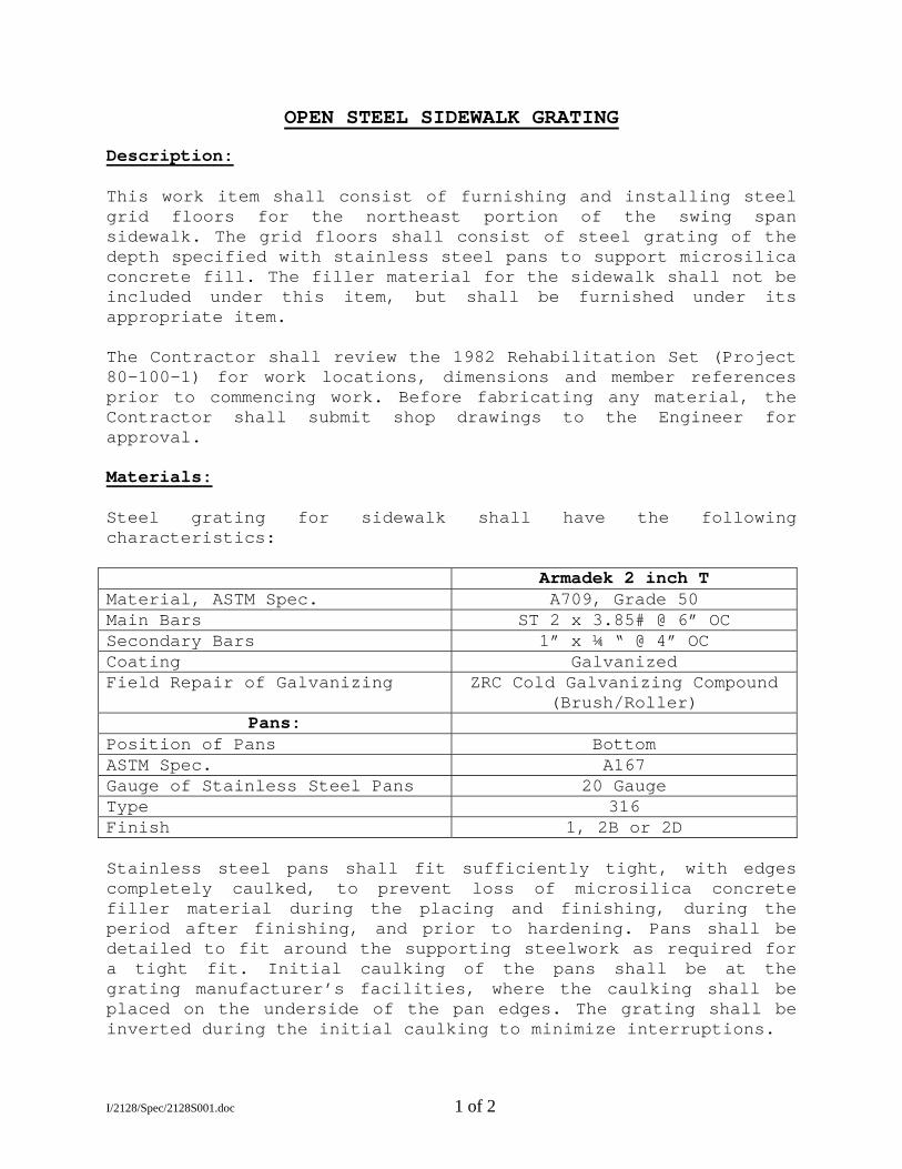
OPEN STEEL SIDEWALK GRATING Description: This work item shall consist of furnishing and installing steel grid floors for the northeast portion of the swing span sidewalk. The grid floors shall consist of steel grating of the depth specified with stainless steel pans to support microsilica concrete fill. The filler material for the sidewalk shall not be included under this item, but shall be furnished under its appropriate item. The Contractor shall review the 1982 Rehabilitation Set (Project 80-100-1) for work locations, dimensions and member references prior to commencing work. Before fabricating any material, the Contractor shall submit shop drawings to the Engineer for approval. Materials: Steel grating for sidewalk shall have the following characteristics: Armadek 2 inch T Material, ASTM Spec. A709, Grade 50 Main Bars ST 2 x 3.85# @ 6” OC Secondary Bars 1” x ¼ “ @ 4” OC Coating Galvanized Field Repair of Galvanizing ZRC Cold Galvanizing Compound
(Brush/Roller) Pans:
Position of Pans Bottom ASTM Spec. A167 Gauge of Stainless Steel Pans 20 Gauge Type 316 Finish 1, 2B or 2D Stainless steel pans shall fit sufficiently tight, with edges completely caulked, to prevent loss of microsilica concrete filler material during the placing and finishing, during the period after finishing, and prior to hardening. Pans shall be detailed to fit around the supporting steelwork as required for a tight fit. Initial caulking of the pans shall be at the grating manufacturer’s facilities, where the caulking shall be placed on the underside of the pan edges. The grating shall be inverted during the initial caulking to minimize interruptions.
I/2128/Spec/2128S001.doc 1 of 2
Construction Details: The limits of grating to be replaced include the full width of the existing sidewalk panels (10’- 0”) at the northeast portion of the swing span (east of Floorbeam FB14). Panels of steel grid floor for the sidewalk shall be installed transverse to the bridge and welded to the supports with a 3/16" fillet weld, 1-½ inch long at each side of every bearing bar at every intersection with the support members. Adjacent panels shall be welded to each other. Grating panels must be cut to clear truss members and railing posts at panel intersections similar to the existing grating. Edge bars at these grating cutouts shall be full depth and ¼” in thickness. All details not otherwise noted, such as spacing between panels, weld types, and sizes, shall be in accordance with the manufacturer’s recommended practice as shown on the approved shop drawings. Edge bars and connection plates shall be provided as required. Trim plates and end angles shall be included as part of the grating. Stainless steel pans shall be installed in the steel grating, welded in place, and completely caulked to form a substantially tight surface for the placement of microsilica concrete filler material. After erection, all main bearing bars shall be straight, and all parts shall be flush on top. Method of Measurement: Work under the item “Open Steel Sidewalk Grating” will be measured for payment by the number of square feet of sidewalk surface of steel grid floor actually placed and accepted as shown on the Shop Drawings or as ordered by the Engineer. Basis of Payment: Payment will be made at the Contract unit price per square foot for “Open Steel Sidewalk Grating”, which price shall include fabricating, sandblasting, galvanizing, furnishing, placing, and all materials, equipment, tools, and labor incidental thereto.
I/2128/Spec/2128S001.doc 2 of 2
MICROSILICA CONCRETE Description:
This work item shall consist of the placement of microsilica concrete fill in the sidewalk grating as specified herein. The sidewalk grating shall be filled to full depth with no overfill.
Materials:
All pertinent provisions of CT Form 814, Article 6.01.02 shall apply, supplemented with the following:
Microsilica concrete shall consist of a homogenous mixture of cement, microsilica admixture, fine aggregate, coarse aggregate, air entraining agent, set retarding water reducing admixture, and water.
Portland cement (Type II), water, fine aggregate and coarse aggregate shall conform to Article M.03.01. Coarse aggregate which is selected by the Contractor is subject to approval by the Engineer, and shall be designed utilizing a maximum size of ½ inch aggregate.
If the microsilica admixture is supplied in the slurry form, the slurry shall be maintained in storage above the temperature of 32 degrees Fahrenheit. Slurries exposed to temperatures of 32 degrees Fahrenheit or less shall be removed and replaced at no cost to the Department. The slurry shall be homogenous and agitated as necessary to prevent separation. The slurry shall be added using proportioning equipment approved by the Engineer. The microsilica slurry admixture shall be added through an existing automation system or a two stop off-line automated batching system. The automated batching system shall meet the following requirements:
Delivery accuracy of ± 1% (by volume)
Program quantity (gallons, nearest tenth)
Batching tolerance ± 2.0% (by volume)
System interlocks
Print Requirements:
a. Date and time b. Truck number (or alternate method relating microsilica to batch ticket) c. Delivered quantity (gallons, nearest tenth)
The control box/printer for a two stop off-line batching system shall be located at the batch plant operator’s workstation unless otherwise approved by the Engineer.
If the microsilica admixture is supplied in the densified powder form, the weight of the densified powder shall be measured cumulatively with the cement. The densified powder shall be last in the measuring sequence and the tolerance for each material drawweight shall be based upon the total weight of the cement plus the densified powder. The batching tolerance for the cement plus densified powder shall be ± ½ % by weight.
The dry unit weight of the finished concrete shall be 148 (+0, -4) pounds per cubic foot, as determined by ASTM C567.
The Contractor shall design and submit to the Engineer, a concrete mix in accordance with the following mix criteria:
I/2128/Spec/2128S002.doc 1 of 4
MIX CRITERIA Cement Content 752 lbs./C.Y. Microsilica Content 6 – 7 % Allowable Air Content 4.0% - 8.0% Allowable Slump 5 – 7 inches Minimum Compressive Strength at 28 Days 5,000 psi
Note: The above criteria are provided for design information, and the data is based on a fine aggregate fineness modulus of 2.80. The mixture proportions shall be determined using actual conditions for fineness modulus and bulk specific gravities (saturated surface dry for aggregate).
A super-plasticizer admixture may be required to improve workability. It shall be utilized in accordance with the admixture manufacturer’s written instructions. Super-plasticizers may only be added with approval of the Engineer.
Construction Methods:
All the pertinent requirements of CT Form 814, Article 6.01.03 shall apply supplemented with the following:
Equipment: The Contractor shall utilize a central mix plant to batch the microsilica concrete.
Technical Representative: The Contractor shall provide the services of a representative of the microsilica manufacturer. This Representative shall be experienced in the use of microsilica concrete and shall be approved by the Engineer. The Representative shall provide advice on the mixing, placement, and curing of the microsilica grating fill. The Representative is to be present prior to placing operations to inspect the prepared surface and during the first day of placement operations.
Schedule of Equipment and Operations: At least thirty (30) days before the commencing of these operations, the Contractor shall submit procedures to demonstrate compliance with ACI 306 “Standard Practice for Cold Weather Concreting”, and ACI 305 “Hot Weather Concreting”, in accordance with Article 1.05.02 for review by the Engineer. This information shall include details of equipment to be used in placing and finishing of the concrete, including the number and type of personnel who will be engaged in placing the concrete. The personnel shall consist exclusively of persons with skill and experience appropriate to their working assignments.
Mixing, Placing and Finishing: No microsilica concrete shall be placed when the ambient air or steel grating surface temperature is lower than 45 degrees Fahrenheit. No microsilica concrete shall be placed when the air or steel grating surface is greater than 80 degrees Fahrenheit or when it is forecast that the ambient temperature will exceed 80 degrees Fahrenheit within 4 hours from the beginning of the proposed placement time, unless the Contractor demonstrates to the Engineer’s satisfaction that the evaporation rate is less than 0.15 lbs. per square foot per hour and will not exceed this rate within 4 hours from the beginning of the grating fill placement. Plastic concrete temperature shall be between 60 and 80 degrees Fahrenheit.
The Contractor shall satisfy the Engineer that all necessary finishing tools, equipment, and manpower are on hand at the site of work, and that experienced finishers will be employed to finish the microsilica concrete surface. Placing microsilica concrete shall conform to the pertinent requirements of Subarticles 6.01.03-09 and 12.
Placement in the gratings shall be continuous, stopping only at the joints. Placement for the sidewalk shall be struck flush with the top of the grating. No overfill is permitted for sidewalk.
I/2128/Spec/2128S002.doc 2 of 4
The microsilica concrete discharged from the mixer shall be uniform in composition and consistency. It shall be placed to approximately ¼ inch above grade and then screeded with approved finishing equipment. The microsilica shall be broom (or brush) finished. Hand finishing with wood floats may be required along the edge of the placement.
Placement and finishing equipment shall satisfy the following requirements:
Hand tools may be used for placement and brushing-in of and for distributing the microsilica concrete fill to correct level for screeding. Hand operated vibrators and screeds may be used to place and finish small areas of work.
A bulkhead shall be installed in case of a major delay (greater than 1 hour) in the placement operations. During minor delays, the placement shall be protected from drying with several layers of wet burlap.
Adequate precautions shall be taken to protect freshly placed concrete from sudden or unexpected rain. The Engineer may order the removal and replacement of any material damaged by rainfall, at the Contractor’s expense.
Test Cylinders: Department personnel shall cast cylinders for 4, 7, and 28-day comprehensive strength tests. If the Contractor prefers additional cylinders, a request must be made to the
Engineer. The Contractor must provide adequate curing conditions by both methods as follows:
a) Curing box, and b) cured in the field under the same conditions as the filled bridge deck grating. Test Blocks: Three test blocks shall be cast and cured and adequately weighed within one week prior to placement. Deviation from the specified unit weight may require revisions to balance calculations. Placement of the concrete will not be permitted until a comparison between the actual unit weight and the specified unit weight has been completed and any necessary adjustment to ensure span balance has been made. Three additional test blocks shall be made during the actual placement of the concrete.
During placing and finishing the evaporation rate shall not exceed 0.1 pound per square foot per hour of exposed concrete as determined by ACI 305R-5, Fig. 2.1.5. Possible procedures to control evaporation may include cooling ingredients prior to mixing, use of temporary windbreaks, sun shades, light fog misting above the concrete, and/or these combined with other measures directed by the Engineer.
The concrete for each placement sequence shall be kept constantly moist and protected against any drying action, and cured as indicated hereinafter. Ambient air temperatures during the cure period shall be 50 degrees Fahrenheit or higher. Should the temperature drop below 45 degrees Fahrenheit during curing, measures shall be taken to insure that the temperature of the concrete is maintained at or above 45 degrees Fahrenheit for the cure period. Curing shall be accomplished in the following manner: Fog Spray: Curing of the concrete shall begin by the application of a water fog spray immediately after the finishing operation. Fog spray shall continue until such time as the moist cotton mats are placed. The amount of fog spray shall be strictly controlled so that accumulations of standing or flowing water on the surface of the concrete shall not occur. There shall be a sufficient amount of spray to keep up with the placing operations.
Should atmospheric conditions render the use of fog spray impractical, the Contractor shall use plastic covers of suitable thickness and securely fastened down, but not directly in contact with the deck concrete. The covers shall be used only until the initial set has taken place, whereupon moist cotton mats shall be placed immediately thereafter and kept wet for the duration of the curing period.
I/2128/Spec/2128S002.doc 3 of 4
On the windward side of the panel being cured, the Contractor shall erect barriers of suitable height, when necessary, to protect the curing concrete from the direct force of the wind.
Moist Curing: When the concrete has set sufficiently, moist curing shall be substituted for the fog spray. Cotton mats shall be pre-moistened and ready to place on the newly finished concrete surface as soon as placement, consolidation, and finishing of concrete are complete. The mats should then be covered with plastic sheeting to prevent evaporation of the curing water. Additional curing water should be applied through soaker hoses running under the protective plastic sheeting, so that the mats are kept continuously wet throughout the period of cure.
All fresh concrete surfaces shall be kept continuously wet for a period of 48 hours, as approved by the Engineer. The wet curing shall be continuously monitored by the Contractor for this 48 hour period. After the 48 hour wet cure, the curing material shall be removed for an additional ambient air cure.
Concrete Finished Surface Requirements: After the concrete has cured, the surface will be inspected by the Engineer for surface profile, texture, cracks, and delaminations. The concrete surface shall not vary more than 1/8 inch in 10 feet when tested with a 10 foot straightedge. Variations greater than this, which in the opinion of the Engineer adversely affect the riding qualities of the surface, shall be corrected at the expense of the Contractor.
Defective or Damaged Concrete: Minor cracks, as determined by the Engineer, shall be sealed using a method and material recommended by the manufacturer of the microsilica admixture.
In areas of extensive cracking, as determined by the Engineer, the concrete grating fill shall be removed and replaced by the Contractor.
Where delaminations of the concrete grating fill have occurred, as determined by the Engineer, the Contractor shall remove and replace the grating fill.
All repairs or replacement of the concrete grating fill shall be accomplished at no cost to the city.
Time Schedule: No traffic shall be permitted on the concrete grating fill, nor shall the deck units be moved, nor shall the swing span be operated, until a compressive strength of 2,500 psi has been developed as determined by compressive strength tests. Swing span must remain in the closed position during this time.
At least two weeks prior to the concrete placement, a preplacement meeting shall be conducted to review the specification, proposed procedures including concrete and admixture handling, placing, finishing and curing, to facilitate coordination between all parties involved. Individuals attending this meeting should include the Engineer, Contractor, Concrete Supplier, representatives from the Department, and a technical representative from the microsilica manufacturer.
Clean-up water from the concrete operation must be collected and disposed of in accordance with federal, state, and local codes. Any spills must be immediately reported to the Department of Environmental Protection.
Method of Measurement:
Microsilica concrete fill will be measured for payment by the actual number of square feet placed and accepted within the open grating to be filled.
Basis of Payment:
This work will be paid for at the agreed unit price per square foot for “Microsilica Concrete”, completed and accepted, which price shall include test blocks, surface preparation, placement (including pumping, if necessary), curing, crack repair, services of the Technical Advisor, and all materials, equipment, tools, and all labor incidental thereto.
I/2128/Spec/2128S002.doc 4 of 4
REMOVAL OF EXISTING SIDEWALK GRATING Description:
This work item shall consist of the removal and disposal of approximately 95 linear feet of concrete filled steel grating panels. The north east portion of the swing span sidewalk grating is to be removed in preparation for an in-kind replacement. The limits of grating to be removed include the full width of the existing sidewalk panels (10’-0”) at the eastern half of the north sidewalk of the swing span (east of Floorbeam FB14).
The Contractor shall review the 1982 Rehabilitation Set (Project 80-100-1) for work locations, dimensions and member references prior to commencing work. The Contractor shall also examine the structure prior to commencing work in order to make his own determination of the work and conditions to be encountered.
Construction Details:
Prior to the removal of any materials, the Contractor shall erect barricades as required to protect the public by closure of the north sidewalk during this construction work. Any resulting deck openings shall be covered at the end of any workday. Also, if existing deck panels are removed but not immediately replaced with new panels, then the swing span must be temporarily balanced in preparation for any bridge opening.
The Engineer must approve the method of sidewalk panel removal and disposal prior to the Contractor commencing work. All debris shall be promptly cleaned up and removed from the site. Any material that falls into the river as a result of this removal operation shall be reported to the Engineer and then removed from the riverbed by the Contractor immediately. Care shall be taken to assure that the removal operation does not result in any damage to the existing superstructure and railing members.
The existing sidewalk panels are attached with a fillet weld between the main bearing bars and the support members below. See the 1982 Rehabilitation Set (Project 80-100-1) for details and dimensions.
After each existing sidewalk panel is removed, the panel shall be accurately weighed. The weights for each panel shall be recorded and its location documented on a sketch. Upon completion of work, copies of these records shall be turned over to the engineer.
Once the existing sidewalk panels are removed, the Contractor shall grind any excess weld material off the top of the existing sidewalk stringers and other supporting members prior to paint preparation. The resulting exposed portion of the top flange of the support members shall be painted with an organic zinc rich paint. Color and paint system to be compatible with the existing paint system. Method of Measurement: Payment under this item shall be on a lump sum basis and will not be measured for payment. This item includes the complete removal and disposal of the designated sidewalk grating panels from the site along with any required temporary deck opening closures and span balance work to be performed during this construction work. Basis of Payment: Payment will be made at the Contract lump sum price for “Removal of Existing Sidewalk Grating”, which price shall include all materials, equipment, tools and labor incidental thereto. The materials, equipment, tools and labor required for any temporary deck closure work and temporary balance work is also to be included as a part of this lump sum pay item.
I/2128/Spec/2128S003.doc 1 of 1
SECTION 30.01STORM SEWER AND CATCH BASIN LATERAL
30.01.1 DESCRIPTION
This item of work shall consist of the construction and installation of storm sewers and catch basin material all in conformity with the lines, grades, dimensions, material and details shown on the plans or as ordered, in accordance with the provisions of these specifications for the various materials and work.
30.01.2 MATERIALS
a. Pipe
Pipe shall be the class and size shown on the plans or ordered by the Engineer and shall conform to the appropriate materials section of these contract Specifications. Concrete pipe for storm sewers shall be tongue and groove and shall have mortar joints as specified elsewhere.
The Contractor shall not make substitutions for any pipe without the written approval of the Engineer.
b. Tee Branches
Tee Branches will be placed at intervals and of sizes shown on the contract plans or as directed by the Engineer. For pipe 27 inches in diameter or smaller, tee branches with bells to take connection shall be integrally formed or cast into the pipe wall with additional reinforcement provided in the concrete collar surrounding the bell of the tee. For pipe 30 inches in diameter and larger, tee branch shall be cast in the wall of the pipe with a socket for the spigot of the connection pipe.
c. Mortar
Mortar for joints shall conform to Section 2.09 Type 3 of these contract specifications.
30.01.3 CONSTRUCTION METHODS
1. Laying Sewer Pipe
Sewer pipe, both main sewers and lateral sewers shall be of the size, class and type as indicated on the contract plans or ordered by the Engineer or specified elsewhere in the Contract Documents. Pipe shall be laid as indicated on the contract plans or otherwise directed. All pipes, when in place, shall be precisely true to the line and grade specified. Unless otherwise directed, pipe shall be laid up grade without any breaks in the line between manholes or other structures.
a. Where underdrain or special foundation, or special bedding or haunching is not required, pipe shall be bedded in conformance with Class "C” Bedding as defined by the American Concrete Pipe Association and laid as follows: The undisturbed natural soil at the bottom of the trench shall be excavated carefully by hand, just before pipes are set in place, to conform as nearly as possible to the shape and grade of the outside of the lower part of the pipe as shown on the Drawings. Grade of this soil base shall be measured and checked at least once for each length of pipe, and in any case at intervals of not more than four feet apart, immediately before pipe is laid upon it. The base must be such that the barrel of the pipe will be evenly supported for its entire length except for a distance of not over 4 inches outside each end of each pipe joint.
Pipe must not be supported by lumps of soil, sills, shims, etc. Pushing fine material under any pipe laying on its bed will not be permitted. Pipe bed must be formed to correct grade before the pipe is placed.
30-01-1
b. Where an underdrain is laid below pipe, the top of the crushed stone or gravel surrounding the underdrain will be carefully brought to the exact grade of the outside of the barrel of the pipe, as described for soil subgrade. A thin layer of the same material will be spread over the natural soil on each side of the trench dug for the underdrain to provide a measure of drainage from the sides of the work to the underdrain. Thereafter work will be continued as described for pipe laid on natural soil base.
c. Where a foundation of gravel, crushed stone or a stone drain is required by the drawings, or where ordered by the Engineer, the top of the gravel or stone shall be brought carefully to the proper grade for the barrel of the pipe, well tamped or compacted in excavation. The clearances on sides of pipe shall be not less than 6". The bottom of the trench will then be filled with fine material, sand, gravel, crushed stone, or concrete as required or ordered, this fill being well tamped and compacted in place. Then the fill of fine material as above will be smoothed off to grade for the pipe, as described in a previous section for laying pipe on natural soil, and the pipe laid, as described therein.
No separate payment will be made for forming the bottom of the trench to receive the pipe as required by the Contract Plans. All cost in connection therewith shall be included in the contract unit price for excavation.
Each pipe shall be placed into its position in the trench only in such a manner and by such means as the Engineer approves as satisfactory. The Contractor will be required to furnish slings, straps, and other approved devices to permit satisfactory support of all parts of the pipe when it is lifted.
All pipe in main sewer lines will, in general, be laid using a grade string stretched taut above the line of pipe between batter boards of profiles averaging twenty-five feet and not exceeding thirty feet apart. Measurement shall be made down to the bed for each pipe prior to setting it in place and to the end of each pipe when it has been placed, by means of a suitable grade pole. Each pipe shall be brought to line with a plum bob, all of which tools shall be furnished by the Contractor and satisfactory to the Engineer.
Pipe will then be laid accurately to grade and line, inserted firmly against the end of the last pipe previously laid, and held in position.
Sufficient fine soil or other material as required shall then be placed on each side to hold pipe in position while joint is being made. Joints will then be made, as described herein and inspected. Fill of fine granular soil or other material, as required, will then be placed on both sides of pipe in thin layers and tamped. Holes under joints must be completely filled. Suitable tools shall be used to ram the fill tightly under and against the rounded sides of the pipe so that all space on each side of each pipe is entirely filled with well-compacted material.
Open ends of sewers or pipe under construction shall be kept closed with temporary stoppers at night and at other times when they need not be open in order to exclude foreign matter and flows of water which might be detrimental to newly-made joints or other portions of the work under construction. Sewer must be clean, and free from sediment and foreign objects when completed. Contractor may be required to clean inside of sewer before acceptance and also to clean any pre-existing sewers to which his work connects which have become obstructed in part or whole by sediment or foreign materials entering through his work. The City shall not furnish cleaning facilities to Contractor.
Skilled workmen must be employed who can and will accurately excavate to subgrade for pipe. If at any point the subgrade is, by accident, too low, the excess space shall be filled with crushed stone, gravel or concrete, without cost to the City.
30.01-2
All storm sewer pipes shall be laid in a trench free of water. The Contractor shall furnish all equipment necessary to keep the trenches free of water. After the sewer has been placed and backfilled, at least 18 inches over the top of the pipe, the annular space inside the pipe at each joint shall be filled with cement mortar and troweled smooth with the inside of the pipe.
Catch basin laterals shall be located as shown on the contract drawings or as directed by the Engineer. Fifteen-inch (15") reinforced concrete pipe Class V shall be used unless otherwise specified or directed by the Engineer.
2. Pipe Joints
Mortar joints shall be used on storm sewers. Care must be taken to fill annular spaces thoroughly. Any mortar projecting into the interior of the pipes shall be carefully removed before it has set. The interior of the joints shall be wiped smooth and free of mortar and dirt.
3. Plugging and Capping Pipe
Sewers, pipe and laterals shall be plugged as shown on the contract plans. Caps and plugs shall be constructed as shown on the contract drawings or if of a manufacture type, they shall be approved for use by the Engineer.
Plugs and bulkheads constructed of brick shall be constructed with grade MA sewer brick as specified in the A.S.T.M. Specification C-32. Bricks shall be mortared to a neat and plumb bulkhead or plug. The outside surface of all brick plugs or bulkheads shall be pargeted with a one (1) inch thickness of mortar in accordance with the specifications for pargeting of brick manholes.
Manufacturer's shop drawings of all applicable size plugs shall be submitted to the Engineer for approval prior to the installation of any manufactured plug.
No separate payment will be made for plugging and capping and all costs in connection therewith shall be included in the general cost of the contract.
30.01.4 METHOD OF MEASUREMENT
Measurement of reinforced concrete pipe for storm sewer and lateral shall be made by the Engineer. The actual length in lineal feet of pipe laid and accepted in place only shall be measured.
30.01.5 BASIS OF PAYMENT
Payment for all reinforced concrete pipes laid for storm sewers and measured for payment will be paid for at the contract unit price for each respective class and size. Said payment shall include the cost of the pipe, the placement of the pipe, and all labor, material and equipment incidental to the installation of the storm sewer.
Payment for all reinforced concrete pipe laid for laterals will be made at the contract unit price for the respective class and size and such payment shall include the cost of the pipe, the placement of the pipe, and all labor, material and equipment incidental to the installation of the storm sewer.
No additional payment will be made for Tee-Branches; all costs incurred shall be included in the contract price of the sewers to which they are part. They shall be furnished and laid as shown on the contract plans or as specified without extra cost to the City.

30-01-3
SECTION 30.02 SANITARY SEWERS
30.02.1 DESCRIPTION
This item of work shall include the construction and installation or reconstruction or alternation of sanitary sewers all conforming with the lines, grades, dimensions, materials and details shown on the plans or ordered by the Engineer and in accordance with the provisions of the specifications.
30.02.2 MATERIALS
a. Pipe
All pipes shall be as specified in the contract documents and shall conform to the appropriate materials section of these contract specifications. Concrete pipe for sanitary sewers shall be joined with "O" ring rubber gasket and shall be coated on the inside as specified elsewhere herein. The Contractor shall not make substitutions for any pipe without the written approval of the Engineer.
b. "O" Ring Rubber Gasket
The "O" ring rubber gasket shall conform to Section 2.20 Type 5 of these contract specifications.
c. Tee Branches
Tee branches will be placed at intervals and of sizes as called for on the contract plans or as directed by the Engineer. For pipe 27 inches in diameter or smaller, tee branches with bells to take sanitary sewer pipe connections shall be integrally formed or cast into the pipe wall with additional reinforcement provided in the concrete collar surrounding the bell or tee. For pipe 30 inches in diameter and larger, tee branch shall be cast in the wall of the pipe with a socket for the spigot of the connection pipe.
30.02.3 CONSTRUCTION METHODS
1. Inside Pipe Coating
The inside pipe coating shall be applied in accordance with the manufacturer's specifications, but in no case shall there be more than five (5%) percent of thinner added.
2. Laying Sewer Pipe
Construction methods shall conform to Section 30.1.3 of these contract specifications.
3. Joints
The joints shall be sealed with "O" ring rubber gaskets so that the joint will remain tight under all conditions of service. The diameter of the joint surfaces shall not vary from the theoretical diameter by more than 1/16th of an inch. The tongue and groove ends shall be designed to enclose the gasket on four surfaces when the joint is in its final position.
The rubber gasket shall be placed in the groove of the spigot end of pipe previous to laying pipe. After the pipes are aligned in the trench, ready to be joined, all joint surfaces shall be cleaned and immediately prior to joining the pipe the bell shall be completely covered with vegetable soap (such as Diamond "A" soap gasket lubricant) which will not harm the rubber. The pipe shall then be carefully pushed home, the position of the gasket and the joint shall be inspected to assure it has been properly seated and is tight. Suitable devices that will not damage the pipe shall be used to force pipe together. The inside and outside ends of the pipe shall fit within one eighth (1/8) inch.
Details of gasket, attachment and joint formation will, in general, follow directions of manufacturer of the joint material and of the pipe, based upon the design thereof and their experience with such joints elsewhere, all however subject to directions and approval of the Engineer, and the requirements of these specifications.
30-02-1 4. Leakage
It is the intent of these specifications that the leakage within the sanitary and combination sewer system shall be reduced to a practicable minimum, attainable only with first class workmanship.
a. Where practicable, the leakage tests shall be made at a time when the groundwater is at least 1 foot above the top of the pipe of the highest section of work being tested. Leakage into the sewer shall not exceed 200 gallons per inch of diameter per mile of pipe per 24 hours.
b. Where the groundwater level is less than one (1) foot above the top of the pipe, the sewer shall be subjected to an internal pressure by plugging the pipe at the lower end and then filling the sewers and higher manhole with clean water to a height of two (2) feet above the top of the pipe. The leakage out of the sewer will be measured by the volume of water necessary to maintain the water level in the higher manhole. Leakage out of the sewer shall not exceed 200 gallons per inch diameter per mile of pipe per 24 hours.
Should the section under test fail to meet the requirements, and if, in the opinion of the Engineer, it is practicable to locate and repair excessive leakage, the Contractor shall do all work of locating and repairing leaks and resetting that the Engineer may require, without additional compensation.
Cost of all labor, equipment and material which the Contractor is required to furnish for making tests and for reducing leakage and any expense due to delays or inconvenience arising by reason of such tests, waiting for tests, or remedying excess infiltration or leakage shall have been included in prices bid for sewer; and Contractor shall receive no additional compensation therefor.
Sewers constructed under the Contract may be tested for infiltration in several separate sections, as these sections may be completed, all as and when the Engineer may direct. After any section has been tested, the Engineer may, at his discretion, permit connections to be made by other parties; and said sections may be used for drainage or other purposes without waiting until all sewers contemplated under the Contract have been completed and tested. The results of the tests on the separate sections of these sewers, if so tested, shall be combined and totaled by the Engineer for determining if the infiltration or leakage into sewers built under this Contract is within the specified limits.
The shortest length of the sewer to be tested in section at any one time shall be 250 linear feet.
No separate payment will be made for any work in connection with testing, determining and/or repairing any leaks or breaks and all costs in connection therewith shall be included in the contract unit price of the sewer involved. There will be no extensions of contract completion time due to testing or repairs to leaks or breaks.
5. Plugging and Capping Pipe
This item shall conform to Section 30.1.3 of these contract Specifications.
30.02.4 METHOD OF MEASUREMENT
Measurement of reinforced concrete pipe for sanitary sewer shall be made by the Engineer. The actual length in lineal feet of pipe laid and accepted shall be measured.
30.02.5 BASIS OF PAYMENT
Payment for all reinforced concrete pipes laid for sanitary sewers and measured for payment will be paid for at the contract unit price for each respective class and size. Said payment shall include the cost of pipe, approved rubber gaskets, inside coating as specified, and the placement of pipe and rubber gaskets, testing, and all other labor, material and equipment incidental to the installation of the sanitary sewer.
No additional payment will be made for Tee Branches; all costs incurred shall be included in the contract price of the sewers to which they are part. They shall be furnished and laid as shown on the contract plans or as specified without extra cost to the City.

30-02-2
SECTION 30.03HUBS FOR SERVICE LATERALS
30.03.1 DESCRIPTION Hubs for service laterals shall be 6 inches in diameter for sanitary service laterals, 12 inches in diameter for storm service laterals, equal in quality and dimensions to that specified for the sewers. 30.03.2 MATERIALS Pipe for hubs shall comply with the requirements of the Contract Drawings and of Section 2.16 and Section 2.26 of these Contract Specifications. 30.03.3 CONSTRUCTION METHODS Hubs shall be furnished in both sanitary and storm sewer pipe and shall be precast in the pipe by the manufacturer as specified in Section 30.01.2 and Section 30.02.2 of the Contract Documents. The Hubs shall be placed at the locations shown on the Contract Drawings or as directed by the Engineer and shall be offset as shown on the Drawings. The ends of all hubs, not connected with service laterals shall be closed with a vitrified cover, set into the bell of the hub with jute caulked around the circumference of the cap and then lightly cemented in with 1:2 cement mortar to secure the cap and to form a small bead inside the bell. Caps should be set into hubs not less than 24 hours before the pipe is placed and backfilled. All hubs must be so closed that the cap or bulkhead can be removed at a future time without damage to the bell of the hub. Hub pipe damaged from any cause whatsoever, whether in or out of the trench, shall be replaced and removed from site of the work by the Contractor without additional cost to the City. 30.03.4 METHOD OF MEASUREMENT The quantity of hubs to be measured for payment shall be the actual number of hubs as designated on the Drawings or ordered by the Engineer of each size furnished and incorporated into the work and approved by the Engineer. 30.03.5 BASIS OF PAYMENT Hubs will be paid for at the Contract Unit Price for the respective size hub installed, and such payment shall include the cost of casting the hub and all labor, equipment and materials necessary and incidental to placing the hub as directed.
30-03-1
SECTION 30.04 CHIMNEY FOR SERVICE LATERALS
30.04.1 DESCRIPTION
Chimneys for service laterals shall be constructed at the locations shown on the plans, where the invert of the sewer is ten (10) feet or more below the street surface or when directed by the Engineer. Chimneys shall be of polyvinylchloride pipe set into a vertical hub or Tee branch encased in concrete in conformance with the plans and specifications.
30.04.2 MATERIALS
a. Polyvinylchloride pipe shall conform to Section 2.26 of these Contract Documents for full inside diameter extra strength type.
b. Joints shall conform to Section 2.20 of these Contract Documents or any approved equal.
c. Concrete shall conform to Concrete Class "B" AE Section 2.07 of these Contract Documents.
30.04.3 CONSTRUCTION METHODS Chimneys for service laterals shall be built at the locations shown on the Contract Drawings or as directed by the Engineer. The invert of the wye at the top of the chimney shall be set a minimum distance of seven feet (7') below the surface of the street and a maximum of eight feet (8') below the surface of the street. The chimneys shall be constructed of polyvinylchloride pipe, encased in concrete and having a double wye branch at the top to accommodate building service laterals on both sides of the streets, as shown on the contract drawings.
The caps to be used in covering the chimneys shall be the same type and installed in the same manner as those specified in Section 30.03.3. The pipe shall be laid with the male ends toward the outlet. All pipes shall be plumb, tightly fitted together and matched so that when laid in work they will form a drain with a smooth and uniform interior.
For poured bituminous joints the bell and spigot shall be thoroughly cleaned and coated with an approved primer and a closely twisted hemp or oakum gasket in one piece of adequate diameter, saturated with neat cement grout, shall be placed completely around the pipe, solidly and tightly rammed home into the annular space between the pipes with a suitable caulking tool.
After the caulking is completed, a space of one (1) inch deep for pipes eight (8) inches or less in diameter; shall remain between the bell and spigot for filling with the watertight compound.
After a joint is properly caulked, and before the compound is poured, the annular space shall be carefully wiped clean and dry. An approved asbestos pipe joint runner of 1-1/2 square inches in cross section shall then be placed and the compound heated to a temperature of about 400 degrees F., shall be poured into the joint in such a manner that the annular space shall be completely filled to within one-half inch of the outer rim of the bell of the pipe. The asbestos runner shall not be removed from the poured joint until the compound has thoroughly set and in no case shall the runner be removed in less than 15 minutes after the pouring of the joint.
The Contractor may preassemble units when permitted by the Engineer. Such units shall be placed in final position in the trench without any deflection or movement in the joints.
Pipe damaged from handling or any cause whatsoever, whether in or out of the trench shall be replaced, without additional cost to the City.
The chimney shall be encased in concrete as shown on the Drawings.
30.04.4 METHOD OF MEASUREMENT
Measurement for payment for chimneys will be made by the Engineer for the actual length in feet measured in accordance to the pay limits shown on the Contract Drawings.
30.04.5 BASIS OF PAYMENT
Payment for chimneys will be made at the contract unit price for the respective size chimney and such payment shall include the cost of pipe, placement of pipe, concrete encasements, necessary plugs and all labor, materials and equipment necessary for and incidental to complete the construction of the chimneys, with the exception of hubs.
Hubs will be paid for at the Contract Unit Price Per "HUB".
No additional payment will be made to T-branches as specified in Section 30.01.
30-04-1
SECTION 30.05 STANDARD MANHOLES
30.05.1 DESCRIPTION Sanitary and Storm Sewer manholes shall be constructed at the location shown on the plans or as directed by the Engineer. They shall be of brick concrete or concrete masonry construction conforming to these specifications. Precast concrete manholes are not included in this section.
30.05.2 MATERIALS
The materials to be used in the construction shall be those indicated on the plans or ordered by the Engineer and conforming to these specifications.
a. Precast Reinforced Concrete Sections shall conform to the latest A.S.T.M. Specifications C-478 or as specified in these contract specifications.
b. Brick shall conform to the requirements of Section 2.08 of these contract specifications for type MA sewer brick.
c. Mortar shall conform to Section 2.09 of these contract documents.
d. Aluminum manhole steps shall be drop-front type as manufactured by Alcoa Aluminum Company or approved equal. The material shall be of alloy number 6061-T6 and as covered by "Specifications for Structures of Aluminum Alloy "6061-T6" as published in Proceedings, American Society of Civil Engineers, Paper 970, Part 1.
e. Precast concrete masonry units shall conform to the requirements of Section 2.14 of these contract documents.
f. Concrete shall conform to the requirements for concrete class "B" as found in Section 2.07 of the contract documents.
g. Manhole frames and covers shall be supplied by the Contractor and shall conform to the Standard City of New Haven Details and Specifications.
30.05.3 CONSTRUCTION METHODS
Manholes shall be built smooth, well formed and water tight and covered with a standard cast iron frame and cover. Until such time as frames and covers are set, manholes shall be kept covered with plank or temporary covering to protect persons, animals and prevent foreign substances from entering the manhole. All manhole frames and covers will be supplied and set by the Contractor.
The Contractor shall not backfill around any brick or concrete block circular manhole until the masonry work has set for 48 hours or until ordered by the Engineer to backfill. The Contractor shall not permit any wheel load on any circular manhole until permission is granted by the Engineer. Backfilling and loading on non-circular manholes shall be under the direction of the Engineer.
Manholes to and including a depth of ten (10) feet shall have an eight (8) inch thick wall. Manholes having a depth in excess of ten (10) feet shall have a wall thickness of twelve (12) inches below the ten (10) feet depth as shown on the contract plans.
All inverts of manholes shall be either poured in the field or formed of brick. No pipe shall be permitted for invert use in the manholes.
a. Storm Manholes
Manholes on storm sewers shall be constructed of concrete block units or brick as shown on the contract plans. Provisions must be made for all pipes and stubs entering the manhole. At least the top six (6) inches of each manhole shall be constructed of brick, for the purpose of adjusting the elevation of the frame and cover.
b. Sanitary Manholes
Manholes on sanitary sewers shall be constructed of Class B concrete or Grade MA sewer brick and as shown on the contract plans. Provisions must be made for all pipes and stubs entering the manhole. At least the top six (6) inches of each manhole shall be constructed of brick for the purpose of adjusting the elevation of the frame and cover.
30.05-01
Brickwork shall conform to Section 2.8.9 of these contract documents. Shallow manholes shall be constructed of Class "B" Concrete or Grade MA Sewer Brick or Concrete Block Units as shown on the contract plans. The flat slab top section shall be manufactured in accordance with the latest A.S.T.M. Specification C478-61T and as shown on the contract drawings. These manholes shall be built whenever the difference in elevation between the bottom of the frame and the inner top of the influent pipe is less than 4 feet or where ever there is not enough room to corbel the sides of the manhole.
Storm and sanitary manholes shall be built as specified in this section of these specifications and as shown on the contract drawings on existing sewers in the locations shown on the contract drawings.
The existing sewer shall remain undisturbed during construction to insure uninterrupted operation of the line. Upon completion of the manhole, the upper half of the existing pipe within the inside limits of the manhole shall be broken and removed leaving a flush, neat and paved invert through the manhole.
Manhole step shall be built into manhole walls as shown on the contract plans. The top step shall be placed 12 inches to 16 inches below the top of the manhole cover frame. Steps shall be placed not more than 12 inches apart unless otherwise directed by the Engineer. Steps shall project 6 inches inside the manhole.
Except as otherwise indicated or ordered there shall be at the top of each manhole a cast iron frame and cover furnished by the contractor. Cast iron frame shall be set to a full, even bearing on cement mortar at the required line and grade. Flange of frame must not project outside masonry on which it rests. Inner circle of frame should not overhang brickwork more than 1 inch. Special locking, water tight, or other types of frames and covers will be furnished and set where so indicated by drawings or contract documents. After frames are set, care must be exercised that they are not moved or disturbed by other operations such as backfilling, paving work etc., and if disturbed shall be reset on fresh bed of cement mortar.
30.05.4 METHOD OF MEASUREMENT
The quantity of manholes to be measured for payment shall be the number of manholes of each type, furnished and incorporated in the work complete as shown, specified or required.
The depth of a unit shall be the total depth measured from the center of the frame or cover to the invert at the center of the manhole.
30.05.5 BASIS OF PAYMENT
The Contract Price for manholes shall be a unit price for each, type (Storm Manholes or Sanitary Manholes) and shall cover the cost of all labor, materials, plant, equipment and insurance required or necessary to construct the manholes complete with steps, cast iron frame and cover and precast reinforced concrete flat slab top where called for on the contract plans, including the excavation of all materials of whatever nature encountered; except rock when there is a contract unit price for "Trench Excavation in Rock", all temporary sheeting, bracing, bridging, decking, fencing, pumping, backfilling, cleaning up and furnishing and installing all other items necessary to complete this work and do all work incidental thereto, all in accordance with the plans and specifications and as directed by the Engineer.
The pay items shall be:
1. "Standard Storm Manhole: 2. "Standard Shallow Storm Manhole" 3. "Standard Storm Manhole over 10 feet deep" 4. "Standard Sanitary Manhole" 5. "Standard Shallow Sanitary Manhole" 6. "Standard Sanitary Manhole over 10 feet deep"
30-05-02
SECTION 30.05a VALVE PIT DOOR
30.05.1 DESCRIPTION Pump station door shall be constructed at the location shown on the plans or as directed by the Engineer. 30.05.2 MATERIALS The materials to be used in the construction shall be those indicated on the plans or ordered by the Engineer and conforming to these specifications.
Manhole frames and covers shall be supplied by the Contractor and shall manufactured to allow HS-20 loading. This door shall have a handle to allow for lifting and a lock and keys to prohibit entering and tampering.
30.05.3 CONSTRUCTION METHODS The door shall be built watertight and matching to the grade of the highway by adding and adjusting the elevation. The pit shall be kept covered with plank or temporary covering to protect persons, animals and prevent foreign substances from entering the well. All frames and doors will be supplied and set by the Contractor. 30.05.4 METHOD OF MEASUREMENT The quantity of doors to be measured for payment shall be the number of doors, furnished and incorporated in the work complete as shown, specified or required. 30.05.5 BASIS OF PAYMENT The Contract Price for valve pit door shall be a unit price for each door and shall cover the cost of all labor, materials, plant, equipment and insurance required or necessary to install the manholes door complete, cleaning up and furnishing and installing all other items necessary to complete this work and do all work incidental thereto, all in accordance with the plans and specifications and as directed by the Engineer.

30.05a-1
SECTION 30.06
SANITARY DROP MANHOLE
30.06.1 DESCRIPTION Sanitary Drop Manholes shall be constructed at the location shown on the plans or directed by the Engineer. The manhole shall be constructed of brick or concrete in conformance with section on standard manholes. The drop shall be vitrified clay pipe encased in concrete in accordance with this specification and the drawings.
30.06.2 MATERIALS
Materials shall be those indicated on the plans or ordered by the Engineer and they shall conform to the requirements of these specifications.
a. Brick shall conform to the requirements of Section 2.08 of these contract documents Type MA.
b. Concrete shall conform to the requirements for Concrete Class "B" (AE) as found in Section 2.07 of these contract documents.
c. Aluminum manhole steps shall conform to the requirements of Section 30.5.2 of these contract documents.
d. Mortar shall conform to Section 2.09 of these contract documents.
e. Vitrified clay pipes shall conform to Section 2.18 of these contract documents and shall be Full Inside Diameter Extra Strength.
30.06.3 CONSTRUCTION METHODS
Sanitary drop manholes shall be built as shown on the contract plans and in accordance with Section 30.5.3 of these contract documents where applicable.
The manhole drops shall be constructed as indicated on the contract drawings or as irected by the Engineer. d
The manhole drops shall consist of vitrified clay pipe with the necessary fittings, encased in concrete poured in adequate forms and constructed to the dimensions indicated on the contract drawings.
All inverts of manholes shall be either poured in the field or formed of brick. No pipe shall be permitted for invert use in the manhole.
30.06.4 METHODS OF MEASUREMENTS
Measurements of payment for Sanitary Drop Manhole shall be made by the Engineer and shall be considered as two separate items, sanitary manholes and manhole drops. The sanitary manhole shall be measured according to Section 30.5.4 of these contract specifications. The manhole drops shall be taken as the depth, in feet, from the invert of the pipe at the upper limits of the drop, to the invert of the pipe at the lower limit of the drop.
30.06.5 BASIS OF PAYMENT
The payment for sanitary drop manholes shall be considered as two separate items, sanitary manholes and the manhole drops.
Payment for sanitary manholes shall be according to Section 30.05.5 of these contract specifications. Payment for manhole drops will be made at the contract unit price, per linear foot for "Manhole Drops", complete and in place. Said payment shall include the cost of all materials, labor and equipment necessary for and incidental to the completion of manhole drops.
30-06-01
SECTION 30.07 CATCH BASIN AND DROP INLET
30.07.1 DESCRIPTION
Catch basins and drop inlets shall be constructed at the locations shown on the Contract Drawings or as directed by the Engineer. They shall be constructed of brick or concrete block of the types specified and to the dimensions shown on the drawings, complete with frames and grates.
30.07.2 MATERIALS
Materials shall conform to the requirements of the Contract Documents and the Engineer.
A. Brick shall conform to Section 2.08 of these contract documents, Type MA.
B. Precast concrete block units shall conform to Section 2.14 of these contract documents.
C. Mortar shall conform to Section 2.09 of these contract documents Type L.
D. Granite Curb Inlets shall conform to the requirements of Section 40.9 of these Contract Specifications and to he dimensions shown on the Contract Drawings.
E. The Catch Basin Frames and grates shall be supplied by the contract or and shall conform to the Standard City of New Haven Details and Specifications.
30.07.3 CONSTRUCTION METHODS
The top six(6)inches of catch basins and drop inlets shall be built with brick.
The Contractor shall not backfill around any catch basins or drop inlets until the masonry has set for 72 hours or until directed by the Engineer. The Contractor shall not permit any wheel load on any catch basins or drop inlets until permission is granted by the Engineer.
Except as otherwise indicated or ordered, there shall be at the top of each catch basin and drop inlet a frame and grate set to a full even bearing on cement mortar at the required line and grade.
The Contractor shall furnish all catch basin frames and grates, drop inlet frames and grates, and all granite curb inlets.
When the catch basins are connected to a combined sewer, a trap will be placed in the catch basins as shown on the contract plans and according to the dimensions and directions as shown on said contract plans.
30.07.4 METHOD OF MEASUREMENT
The quantity of catch basins and drop inlets to be measured for payment shall be the number of catch basins or drop inlets, incorporated in the work, complete as shown, specified or required.
30.07.5 BASIS OF PAYMENT
Catch basins will be paid for at the Contract Unit Price for each "Catch Basin" complete, which price shall include the cost of all labor, materials, equipment required to construct the catch basins, including all excavation, backfilling, trap when required, frame and grate, granite curb inlet, cleaning up and furnishing and installing all other items necessary to complete this work incidental thereto, all in accordance with the plans and specifications and as directed by the Engineer.
The Contractor's attention is called to the fact that any existing sidewalk and curbing damaged in the installation of the catch basins and drop inlets shall be restored as specified in these contract specifications and said cost shall be included in the unit price for catch basins or drop inlets and no additional payments will be made.
30-07-01
SECTION 30.08 ALTER EXISTING MANHOLE, CATCH BASIN OR DROP INLET
30.08.1 DESCRIPTION The Contractor shall make alterations to existing manholes, catch basins, or drop inlets as shown on the contract drawings and/or as directed by the Engineer. The following types of work will be included under this item: a. Removing existing pipes, b. Inserting new pipes, c. Reconstructing inverts, d. Installing or removing traps,
e. Building up the walls or sides of the existing structure to a new grade where the new grade is greater than three feet above the existing grade. (The measurement is made vertically from the bottom of the existing frame to the bottom of the frame at its new elevation.
f. Cleaning catch basins which have been altered. Supplying and setting a new, or resetting the existing frame, grate, cover, or granite curb inlet will not be considered a part of this item. This work will be considered under Item 30.11 "Supply & Set New, or Reset Existing Manhole, Catch Basin or Drop Inlet Frame, Grate or Cover, and Granite Curb Inlet to Existing Structure". 30.08.2 MATERIALS Materials shall conform to the applicable sections of these specifications and drawings for the specific type of structure being altered. 30.08.3 CONSTRUCTION METHODS If required, frames, grates, covers, and granite curb inlets shall be removed from their present beds. They shall be stored safely at the site if they are to be reset. If they are not to be reused, they shall be delivered to the City at 99 Middletown Avenue by the Contractor. When the proposed grade is to be greater than three feet above the existing grade, the Contractor shall build up the walls or sides of the existing structure so the top of the structure will be of the required size or shape to receive the frame or granite curb inlet at the new grade. All cutting or existing masonry shall be confined to the minimum necessary for installation of new pipes or construction of new inverts. Brick or blocks shall be cut out to the nearest joint. New brickwork shall match the lines and contours of the existing structure and be set in a full mortar bed. Pipes shall be cut flush with the walls and the space between the wall and pipe completely filled with mortar. 30-08-1
Existing pipes shall be plugged with a masonry or concrete bulkhead at least eight inches thick completely closing the pipe and forming a watertight seal. The inside face shall be flush with the structure wall and shall be pargeted with 1/2 inch of mortar. Inverts shall be of brick or concrete as specified for standard manholes. Extreme care shall be used in all cutting of existing masonry and any joints cracked shall be cleaned out and filled. Traps shall be installed at catch basins specified on the plans or directed by the Engineer. Existing traps, which are specified to be removed, shall be completely removed and masonry repointed to fill all the holes as required. Where a catch basin lateral is connected to a manhole and part of the alteration to the catch basin is to plug the lateral at both ends, the plugging of the lateral in the manhole shall not be considered as an alteration to the manhole. All catch basins being altered shall be cleaned. This shall consist of the removal of all debris to the bottom of the catch basin. Cleaning of the new or existing catch basin laterals is considered as part of this specification. 30.08.4 METHOD OF MEASUREMENT Each catch basin, drop inlet or manhole altered shall be measured by the Engineer as a unit. All work performed on the catch basin, drop inlet or manhole (other than setting a new or resetting the existing frame, grate, cover or granite curb inlet) will be considered as one alteration to that unit. 30.08.5 BASIS OF PAYMENT The contract price for "Alter Existing Manhole, Catch Basin or Drop Inlet” shall be a unit price for each catch basin, drop inlet, or manhole altered and shall cover the cost of all labor, materials, equipment and insurance required or necessary to complete the alteration all in accordance with the plans and specifications and as directed by the Engineer. The Contractor's attention is called to the fact that any existing pavement, curbing, sidewalk, frames, grates, covers or granite curb inlets damaged during the process of this work shall be replaced in accordance with these contract specifications and said cost shall be included in the contract unit price for alterations and no additional payments will be made under any other item of work.

30-08-2
SECTION 30.09 DISMANTLING AND PLUGGING EXISTING STRUCTURES
30.09.1 DESCRIPTION Manholes, catch basins and existing sewer lines shall be abandoned and plugged where indicated on the contract drawings or as directed by the Engineer. 30.09.2 MATERIALS Brick shall conform to the requirements of Section 2.08 of these contract documents Type MA. Mortar shall conform to the requirements of Section 2.09 of these contract documents. 30.09.3 CONSTRUCTION METHODS The Contractor shall dismantle all manholes and catch basins as shown on the contract plans or as directed by the Engineer. The frames, grates and covers of all dismantled manholes and catch basins shall be salvaged and turned over to the City of New Haven and delivered to Central Services, Middletown Avenue, New Haven, Connecticut. All concrete, brickwork or masonry in dismantled catch basins and manholes shall be removed to such depth that it will not encroach upon the base or sub-base course of any of the new sewers or appurtenances or of any pavement. If any of the existing structure still remains, the influent and effluent pipe in said manholes and catch basins shall be plugged with concrete and the remaining structure shall be filled with an approved backfill material, thoroughly compacted to the top of the existing masonry. All concrete, (including bases) brickwork and masonry of catch basins and manholes to be removed shall be completely removed and shall be disposed of. No materials removed from catch basins or manholes shall be used as backfill. All existing sewers marked to be abandoned shall be plugged with brick and mortar forming a solid water tight bulkhead at least 8 inches thick. 30.09.4 METHOD OF MEASUREMENT This item will not be measured for payment. Where a catch basin lateral is connected to a manhole and part of the dismantling of the catch basin is to plug the lateral at both ends, the plugging of the lateral in the manhole shall not be considered as an alteration to the manhole. 30.09.5 BASIS OF PAYMENT All costs incurred in carrying out the work involved in this section shall be included in all the contract unit prices of this contract and no separate payment will be made for any work involved.
30-09-1
SECTION 30.10 SERVICE LATERALS
30.10.1 DESCRIPTION Service laterals for existing or future connections to the sewer shall be constructed of the sizes, classes and kinds shown, or required and at the locations shown on the plans or directed by the Engineer. 30.10.2 MATERIALS A. Extra strength vitrified clay pipe shall conform to Section 2.18; concrete pipe shall conform to Section 2.16 or 2.17 whichever is applicable; cast iron pipe shall conform to Section 2.19. Type of pipe to be used shall be as shown on the contract drawings or as specified in these specifications under special provisions. B. Joint material shall conform to the requirements of Section 2.20 of these contract specifications for the applicable pipe type. 30.10.3 CONSTRUCTION METHODS Service laterals shall be installed at the locations shown on the plans, or as directed by the Engineer. The minimum grade for service laterals shall be one per cent (1%). All requirements pertaining to the laying of sewer pipe as specified in Section 30.1.2 or Section 30.2.3 of these specifications, where applicable, shall apply to the installation of service laterals. 30.10.4 METHOD OF MEASUREMENT Measurement for payment for service laterals shall be made by the Engineer, for the actual length, in lineal feet, of service lateral installed and accepted in place. Trench excavation will be measured in accordance with Section 20.2.5. 30.10.5 BASIS OF PAYMENT Payment for service laterals will be made at the contract unit price per linear foot for the respective kind and size, and such payment shall include the cost of furnishing the pipe, installing of pipe, and all labor, materials and equipment incidental to the installation of the service laterals. Excavation will be paid for at the contract unit price for the respective type of trench excavation.
30-10-1
SECTION 30.11
SUPPLY AND SET NEW, OR RESET EXISTING MANHOLE, CATCH BASIN OR DROP INLET FRAME, GRATE OR COVER, AND GRANITE CURB INLET TO EXISTING STRUCTURE
30.11.1 DESCRIPTION
The Contractor shall supply and set new, or reset existing catch basin or drop inlet frames, grates and granite curb inlets, or manhole frames and covers to existing or new grades all as shown on the plans and/or as directed by the Engineer. A frame and cover or grate, and granite curb inlet will be considered as a group under this section.
When the new grade is greater than three feet above the existing grade, the work and material required to build up the walls or sides of the existing structure, so the top of the structure will be of the required size or shape to receive the group at the new grade, will not be considered under this section, but will be considered under Section 30.08, "Alter Existing Manhole, Catch Basin or Drop Inlet", of these contract specifications.
30.11.2 MATERIALS
The materials to be used in the construction shall be those indicated on the plans or ordered by the Engineer and they shall conform to the requirements of Sections 2.07, 2.08, 2.09, 30.5 and 30.7 wherever applicable.
Cast iron, for frames and covers shall conform to American Society of Testing Materials (ASTM) Standard Specification for Gray Iron Castings, ASTM Designation A 48 Class 25 B for frames and 30 B for covers.
Steel for catch basins shall be as noted in the plans.
Paint shall be red lead past in oil conforming to AASHO M-71 and finish coat shall be semi-green enamel conforming to the Connecticut Department of Transportation Specification Form 811 Section M.07.14(2) Color #510, page 551.
30.11.3 CONSTRUCTION METHODS
The frame, cover, or grate and granite curb inlet shall be removed from their present bed. They shall be stored safely at the site it they are to be reset. If they are not to be reused, they shall be delivered to the City at 34 Middletown Avenue by the Contractor.
When specified on the plans, new frames, grates, covers and granite curb inlet shall be supplied by the Contractor and shall conform to the Standard City of New Haven Details and Specifications.
Where the top of the structure is not of the required size or shape to receive the frame or granite curb inlet, the Contractor shall reconstruct and reinforce the structure so the frame or granite curb inlet will have full bearing on the structure. Frames and granite curb inlets shall be set in an even bed of mortar.
30.11.4 METHOD OF MEASUREMENT
Each manhole, catch basin or drop inlet to which a new group has been supplied and set, or existing group reset, will be measured as a unit.
30.11.5 BASIS OF PAYMENT
Payment under this item will be as follows:
a) Each manhole, catch basin or drop inlet to which a new group has been supplied and set, shall be paid for at the contract unit price for "Supply and Set New Group to Existing Manhole, Catch Basin or Drop Inlet", or
b) Each manhole, catch basin or drop inlet which has had its existing group reset shall be paid for at the contract unit price for "Reset Existing Group to Existing Manhole, Catch Basin or Drop Inlet",
Complete in place which price shall include all materials (including new frame, cover or grate and granite curb inlet when specified), equipment, and tools and labor incidental thereto, all in accordance with the plans and specifications and as directed by the Engineer.
The Contractor's attention is called to the fact that any existing pavement, curbing or sidewalk damaged during the process of this work shall be replaced in accordance with these contract specifications and said cost shall be included in the contract unit price for setting or resetting, and no additional payments will be made under any other item or work.
The Contractor's attention is called to the fact that any frames, grates, covers or granite curb inlet damaged during the resetting operation will be replaced by the Contractor at no extra cost to the City of New Haven.
30.11-01
SECTION 30.12 UNDERDRAINS
30.12.1 DESCRIPTION Underdrains shall consist of perforated pipe laid in a trench refilled with aggregate. They shall be constructed in accordance with the dimensions and details indicated on the plans and in conformity with these specifications. They shall be classed as "Underdrains", "Storm Water Underdrains" or "Foundation Underdrains", as indicated on the plans. 30.12.2 MATERIALS The materials for this work shall conform to the following requirements:
1. Pipe for underdrains shall conform to the Section 2.22 of these contract specifications for the type of pipe shown on the drawings.
2. Aggregates for filling the trench shall consist of clean, tough,
durable pieces of broken stone or screened gravel meeting the following gradation requirements:
SQUARE MESH SIEVES PERCENT Passing 5/8" 100 Passing 1/2" 90-100 Passing 3/8" 30-100 Passing No. 4 0-80 Passing No. 8 0-35 Passing No. 100 0-2 The Engineer may direct that concrete sand shall be substituted for the above aggregate, in which cases the concrete sand shall meet the requirements of Section 2.07 of these contract specifications. In any case, the broken stone, screened gravel or concrete sand shall not contain more than 3% by weight of stonedust, clay or silt.
3. Mortar for sealing joints shall conform to Section 2.20 of these contract specifications.
30.12.3 CONSTRUCTION METHODS The trench for the underdrain shall be excavated in conformity with the requirements of Section 20.2. The dimensions of the trench shall be as indicated on the plans or as ordered. Where the bottom of the trench is unstable, sufficient unstable material shall be removed and aggregate added to stabilize the bottom of the trench. Where the perforations are to be at the bottom of the pipe, the aggregate for filling the trench shall then be placed to a depth of 3 inches and tamped true to grade. The pipe shall be placed and firmly bedded on the aggregate. Where the perforations are to be at the top of the pipe, the pipe shall be laid directly on the bottom of the trench. After the pipe has been carefully laid and aligned, the joint shall be completed. 30-12-1
When perforated concrete pipe is used, the pipe shall be installed with the hub end up grade and with spigot end entered fully into the adjacent hub. The perforations shall be at either the top or bottom of the pipe as directed; the joints shall be cemented with mortar, finished smooth on the inside and outside of the pipe. When asphalt coated corrugated metal pipe is used, the pipe shall be installed with perforations at either the top or bottom of the pipe as directed. Adjoining pieces of pipe shall be carefully butted together and held by bands or other approved means so as to prevent any displacement of the joint. After the pipe has been installed as described above, the aggregate shall be placed carefully around and over the pipe to a height of 12 inches above the top of the pipe. The remainder of the trench shall be filled with aggregate, as shown on the plans, tampered in layers. When perforated concrete pipe is used with the perforations placed up in all cases where sand is used instead of the aggregate, 2 inches in thickness, shall be placed over the pipe, unless specifically ordered omitted by the Engineer. In all cases where subbase material is to be placed over underdrains, a layer of at least 6 inches of subbase material shall be placed over the underdrain immediately after its completion. 30.12.4 METHOD OF MEASUREMENT This work will be measured for payment by the actual number of linear feet of underdrians, foundation underdrains, and storm water underdrains respectively, completed and accepted and measured in place. Excavation for trench will be measured for payment in accordance with Section 20.2 of these contract specifications. 30.12.5 BASIS OF PAYMENT This work will be paid for as follows:
1. Underdrains will be paid for at the contract unit price per linear foot for "Underdrains," "Foundation Underdrains," and "Storm Water Underdrains,” respectively, complete in place, which price shall include pipe of the type and size specified and all materials, equipment, tools and labor incidental thereto.
2. Trench Excavation will paid for in accordance with Section 20.2 of these contract specifications at the contract unit price per cubic yard for "Trench Excavation" of the applying depth.
30-12-2
SECTION 30.13 PRECAST MANHOLES
30.13.1 DESCRIPTION Precast manholes shall be installed at the locations shown on the plans or as directed by the Engineer. They shall consist of precast reinforced concrete sections, eccentric conical transition sections, and precast base sections conforming with the precast manhole details of the Contract Drawings. 30.13.2 MATERIALS The materials to be used in the construction shall be those indicated on the plans, ordered by the Engineer and conforming to these Specifications.
A. Precast reinforced concrete sections shall conform to the latest A.S.T.M. Specifications C-478.
B. Brick shall conform to the requirements of Section 2.08 of these contract specifications for type MA sewer brick.
C. Mortar shall conform to Section 2.09 of these contract specifications.
D. Aluminum manhole steps shall be drop-front type as manufactured by Alcoa Aluminum Company or approved equal. The material shall be of alloy number 6061-T6 and as covered by "Specifications for Structures of Aluminum Alloy 6061-T6" as published in Proceedings, American Society of Civil Engineers, Paper 970, Part 1.
E. Gasket shall be rubber "O" Ring type, and shall conform to Section 2.20 of these contract specifications.
F. Concrete shall conform to the requirements for concrete Class "B" as defined in Section 2.07 of these Contract Specifications.
G. Manhole frames and covers shall be supplied by the Contractor and shall conform to the Standard City of New Haven Details and Specifications.
30.13.3 CONSTRUCTION METHODS Precast manhole sections shall be manufactured in accordance with the latest A.S.T.M. Specifications C478. Joints of manhole sections shall be formed entirely of concrete employing a rubber "O" gasket and when assembled shall be self-centering and make a uniform watertight joint. Except for those surfaces within the gasket groove, all inside surfaces of the bell or outside surfaces of the spigot, or both, on which the rubber gasket may bear during the closure of the joint and at any degree of partial closure shall be parallel within 1 degree and have an angle of not more than 2 degrees with the longitudinal axis of the pipe. In joints formed entirely of concrete, the distance from either side of the gasket to the end of the bell or spigot shall not be less than 3/4 inch. The gasket spaces between the bell or spigot shall be so shaped as to provide grooves that will prevent the gasket from disengaging from its compression surface or being blown out by hydrostatic pressures. The gasket shall be the sole element utilized in sealing the joint from either internal or external hydrostatic pressure. All manhole steps shall be built into walls of the precast sections and set in straight alignments so as to form a continuous ladder with a maximum distance of 12 inches between steps.
Each section of the precast manhole shall have not more than two lifting holes for the purpose of handling and laying. These holes shall be tapered and shall be plugged with mortar after installation.
30.13-01
Precast base sections shall be installed on a firm stabilized foundation prepared similar to that required for the proper installation of the adjacent pipeline as described elsewhere in these contract specifications under Section 30.01.03. The bell of the manhole base should be wiped clean, be free of all dirt and grit and liberally soaped in preparation for receiving the riser, cone or slab top section. Prior to snapping the gasket into the spigot groove of the riser or cone section, the gasket should be wiped clean and well soaped. The riser or cone section with gasket in place should then be lowered into the bell of the manhole base, taking care that no dirt gets into the joint or on the gasket. Additional riser or cone sections should be joined in a similar manner. Knockouts in manhole riser sections, to allow the installation of pipes may be provided during manufacturing of the riser section and shall be provided only to the maximum allowable pipe size recommended by the manufacturer. Precast base sections may be supplied by the manufacturer with inverts precast or the inverts may be cast in the field by the Contractor. Inverts shall be smooth and accurately shaped to a semi-circular bottom conforming to the inside of the adjacent sewer sections. Changes in direction of the sewer and entering branches shall have a circular curve of as large a radius as the manhole will permit or as shown on the Contract Plans. The influent and effluent pipe shall be joined to the base of the manhole with a rubber gasket and mortar. No pipe shall be permitted for invert use in the manholes. The standard cast iron frame and cover will be installed as specified in these Specifications and will be supplied by the Contractor. 30.13.4 METHOD OF MEASUREMENT The quantity of precast manholes to be measured for payment shall be the number of precast manholes furnished and installed complete as shown specified or required. The depth of the unit shall be the total depth as measured from the center of the frame or cover to the invert at the center of the manhole.
30.13.5 BASIS OF PAYMENT The contract price for precast manholes shall be a unit price for each and shall cover the cost of all labor, materials, equipment and precast sections required to install the manholes complete with steps and frame and cover including excavation, backfilling, cleaning up and furnishing and installing all other items necessary to complete the work and do all work incidental thereto, all in accordance with the plans and specifications and as directed by the Engineer. Pay Items Shall Be: Standard Precast Storm Manholes Standard Shallow Precast Storm Manholes Standard Precast Storm Manhole over 10' Deep Standard Precast Sanitary Manholes Standard Shallow Precast Sanitary Manholes Standard Precast Sanitary Manholes over 10' Deep
30-13-02
SECTION 30.14 "TEE" MANHOLES
30.14.1 DESCRIPTION "Tee" Manholes shall be installed at the locations shown on the Contract Plans or as directed by the Engineer. They shall consist of a Manhole Entrance Tee, Precast Reinforced Concrete Manhole Riser Sections and an eccentric manhole cone or entrance flat slab (for shallow manholes), all conforming to the Contract Documents and Specifications. 30.14.2 MATERIALS The materials to be used in the construction shall be those indicated on the plans, ordered by the Engineer and conforming to these Specifications.
A. Precast reinforced concrete manhole sections shall conform to the latest A.S.T.M. Specifications C-478.
B. Brick shall conform to the requirements of Section 2.08 of these Contract
Specifications for type MA sewer brick.
C. Mortar shall conform to Section 2.09 of these Contract Specifications.
D. Aluminum manhole steps shall be drop-front type as manufactured by Alcoa Aluminum Company or approved equal. The material shall be of alloy number 6061-T6 and as covered by "Specifications for Structures of Aluminum Alloy 6061-T6" as published in Proceedings, American Society of Civil Engineers, Paper 970, Part 1.
E. Gasket shall be rubber "o" Ring Type, and shall conform to Section 2.20 of
these Contract Specifications. F. Concrete shall conform to the requirements for concrete Class "B" as defined
in Section 2.07 of these Contract Specifications.
G. Manhole frames and covers shall be supplied by the Contractor and shall conform to the Standard City of New Haven Details and Specifications.
30.14.3 CONSTRUCTION METHOD Manhole Entrance Tees shall be either eccentric or concentric as specified on the Contract Drawings and shall conform to A.S.T.M. Specifications C-76 and C-478. The branches or risers of manhole entrance tees shall have a 48-inch internal diameter. The run size shall be as noted on the Contract Drawings. The run-laid-length shall be considered to be eight (8) feet. Precast manhole sections shall be manufactured in accordance with the latest A.S.T.M. Specifications C478. Joints of the manhole sections shall be formed entirely of concrete employing a rubber "o" gasket and when assembled shall be self-centering and make a uniform watertight joint. Except for those surfaces within the gasket groove, all inside surfaces of the bell or outside surfaces of the spigot, or both on which the rubber gasket may bear during the closure of the joint and at any degree of partial closure shall be parallel within 1 degree and have an angle of not more than 2 degrees with the longitudinal axis of the pipe. In joints formed entirely of concrete, the distance from either side of the gasket to the end of the bell or spigot shall not be less than 3/4
30.14-01 inch. The gasket spaces between the bell or spigot shall be so shaped as to provide grooves that will prevent the gasket from disengaging from its compression surface or being blown out by hydrostatic pressures. The gasket shall be the sole element utilized in sealing the joint from either internal or external hydrostatic pressure. All manhole steps shall be built into walls of the precast sections and set in straight alignments so as to form a continuous ladder with a maximum distance of 12 inches between steps. Each section of the precast manholes shall have not more than two lifting holes for the purpose of handling and laying. These holes shall be tapered and shall be plugged with mortar after installation. The manhole Entrance "Tee" Section shall be installed in accordance with Section 30.01 or 30.02 for storm and sanitary respectively. If a change in grade is indicated in the manhole the steeper grade shall control for the tee section pipe installation. After installation of the Manhole Entrance "Tee" section, the bell at the entrance tee shall be wiped clean and be free of all dirt and grit, and liberally lubricated with a vegetable soap for receiving the riser, cone or flat slab top sections. Prior to snapping the rubber gasket into the spigot groove of the riser, cone or flat slab top section, the gasket and spigot shall be wiped clean and lubricated with vegetable soap. The riser, cone or flat slab top with gasket in place shall then be lowered into the joint or on the gasket. Additional riser, cone or flat slab shall be installed in the same manner. Care shall be taken to assure that the manhole steps form a continuous ladder. Knockouts in manhole risers to allow the entrance of pipes may be provided during manufacture of riser unit, and shall be provided only to the maximum allowable pipe size recommended. The standard cast iron frame and cover will be installed as specified in Section 30.5 of these Specifications and will be supplied by the Contractor. 30.14.4 METHOD OF MEASUREMENT The quantity of "Tee" Manholes to be measured for payment shall be the number of "Tee” Manholes of the type furnished and installed complete as shown specified or required. The depth of the unit shall be the total depth as measured from the center of the frame or cover to the invert at the center of the manhole. 30.14.5 BASIS OF PAYMENT The Contract Unit Price for "Tee" Manholes shall be a unit price for each and shall cover the cost of all equipment, labor and materials required to furnish and install the manholes complete with steps and frame and cover, including excavation, backfilling, cleaning up and furnishing and installing all other items necessary and incidental to completing this work in accordance with the Plans and Specifications or as directed by the Engineer. Pay Items Shall Be: "Standard "Tee" Storm Manhole" "Standard Shallow "Tee" Storm Manhole" "Standard "Tee" Storm Manhole over 10 feet deep" "Standard "Tee" Sanitary Manhole" "Standard Shallow "Tee" Sanitary Manhole" "Standard "Tee" Sanitary Manhole over 10' deep"

30-14-2
SECTION 2.26 POLYVINYL PIPE
2.26.1 DESCRIPTION These Specifications cover polyvinylchloride (PVC) pipe intended to be used for the conveyance of sewage and stormwater. A. Pipe, Fittings, and Specials: 1. Pipe and fittings including those required for stubs: ASTM D3034 or ASTM F679.
Pipe stiffness (PS): 46 psi minimum. 2. Straight pipe in lengths 13 ft. maximum. Y-branches in lengths 3 ft. maximum. Saddle Y-branches NOT ACCEPTABLE. 3. Specials as specified and to meet the specifications for straight pipe insofar
as applicable and to the details indicated. B. Joints: 1. Joints to conform to ASTM 3212.
2. Push-on bell and spigot joints with elastomeric ring gaskets.
3. Gaskets conform to ASTM F477; resistant to common ingredients of sewage and
industrial wastes, including oils and groundwater, capable of enduring permanently under conditions of proposed use. Fix gaskets into place in bells to avoid dislodging during joint assembly.
2.26.2 INSPECTION AND REJECTION OF SIZE A. Furnish all labor necessary to assist the Engineer in inspecting pipe upon
delivery. Remove rejected pipe immediately. B. All pipe of any manufacturer may be rejected if more than five unsatisfactory
joint assembly operations or "bell breaks" in 100 consecutive joints, even if they conform to ASTM Specifications. Remove all unsatisfactory pipe of that manufacturer of same shipment from work and furnish from another manufacturer conforming to these specifications. C. All tests made in accordance with methods prescribed by ASTM specifications and the acceptance or rejection is based on the test results.
2.26.3 SUBMITTALS A. Shop drawings and descriptive literature showing pipe dimensions, joints,
joint gaskets, pipe stiffness, and other details for each size of pipe indicated. B. Gasket and pipe manufacturers' joint assembly directions. C. Certification with each delivery, that pipe complies to this specification. D. Certified copies of test reports, with each delivery, stating compliance with
ASTM D3212, ASTM F477, and ASTM D3034 or ASTM F679.
30.15-01
11152242.26-1
SECTION 30.16 SPECIAL SANITARY MANHOLES
30.16.1 DESCRIPTION
Special sanitary manholes shall be constructed on existing sanitary sewer at the locations shown on the plans. They shall consist of:
A. Cost-in-place special concrete manhole bases as indicated on the Drawings.
B. Precast reinforced concrete manhole sections as indicated on the Drawings.
30.16.2 MATERIALS
The materials to be used in the construction shall be those indicated on the plans, ordered by the Engineer and conforming to these Specifications.
A. Precast reinforced concrete sections shall conform to the latest ASTM Specifications C-478.
B. Brick shall conform to the requirements of Section 2.08 of these contract specifications for type MA sewer brick.
C. Mortar shall conform to Section 2.09 of these contract specifications.
D. Aluminum manhole steps shall be drop-front type as manufactured by Alcoa Aluminum Company or approved equal. The material shall be of alloy number 6061-T6 and as covered by "Specifications for Structures of Aluminum Alloy 6061-T6" as published in Proceedings, American Society of Civil Engineers, Paper 970, Part 1.
E. Gasket shall be rubber "O" Ring type, and shall conform to Section 2.20 of these Contract Specifications.
F. Concrete shall conform to Section 2.07 of these Contract Specifications.
G. Manhole frames and covers shall be supplied by the Contractor and shall conform to the Standard City of New Haven Details and Specifications.
H. Resilient connectors shall conform to the latest ASTM Specifications C-923, and conforming to manufacturer's standards.
I. Watertight joint shall conform to related standards and manufacturer's instruction.
30.16.3 CONSTRUCTION METHOD
A. Construction of the cast-in-place concrete base shall conform to Section 60.01 of these Contract Specifications.
B. Construction of the precast reinforced concrete manhole sections shall conform to Section 30.13 of these Contract Specifications.
C. Construction sequence of the special sanitary manhole shall conform to the notes on the Drawings and/or as directed by the Engineer.
D. Existing sewers marked "Plug" shall be plugged with brick and mortar forming a solid watertight bulkhead at least 8 inches thick.
30.16.4 METHOD OF MEASUREMENT
The quantity of special storm manholes to be measured for payment shall be the number of "Special Sanitary Manhole" constructed and completed as shown on the Contract Drawings. shall be a unit price for each and shall cover the cost of all equipment, labor and materials required to construct the manhole complete with steps and frame and cover, including excavation, backfilling, cleaning up and furnishing and installing all other items necessary and incidental to completing this work in accordance with the Plans and Specifications or as directed by the Engineer.
30.16.5 BASIS OF PAYMENT
The Contract Unit Price for "Special Sanitary Manhole" shall be a unit price for each and shall cover the cost of all equipment, labor and materials required to construct the manhole complete with steps and frame and cover, including excavation, backfilling, cleaning up and furnishing and installing all other items necessary and incidental to completing this work in accordance with the Plans and Specifications or as directed by the Engineer.
30-16-01
SECTION 30.17 CATCHBASIN MANHOLES
30.17.1 DESCRIPTION
A. Catch basin manholes shall be constructed at the location shown on the Contract Drawings or as directed by the Engineer. They shall be constructed of brick or concrete block of the type specified and to the dimensions shown on the drawings, complete with frames and grates.
B. The Contractor may install precast catch basin manholes as an option.
30.17.2 MATERIALS The materials to be used in the construction shall be those indicated on the plans or ordered by the Engineer and conforming to these specifications.
A. Brick shall conform to the requirements of Section 2.08 of these Contract Specifications for type MA sewer brick.
B. Precast concrete units shall conform to the requirements of Section 2.14
of the Contract Documents.
C. Concrete shall conform to the requirements for concrete Class "B" as found in Section 2.07 of the Contract Documents.
D. Precast Reinforced Concrete Sections shall conform to the latest ASTM
Specifications C76 or as specified in these Contract Specifications.
E. Mortar shall conform to Section 2.09 of these Contract Documents.
F. Aluminum manhole steps shall be drop-front type as manufactured by Alcoa Aluminum Company or approved equal. The material shall be of alloy number 6061-T6 and as covered by "Specifications for Structures of Aluminum Alloy "6061-T6" as published in Proceedings, American Society of Civil Engineers, Paper 970, Part 1. G. Granite Curb Inlets shall conform to the requirements of Section 40.09 of
these Specifications and to the dimensions shown on the Contract Drawings.
H. Catch basin Frames and Grates shall be supplied by the Contractor and
shall conform to the City of New Haven Details and Specifications. 30.17.3 CONSTRUCTION METHODS Catch basin manholes shall be constructed on concrete block units or brick as shown on the Contract Plan. Provisions must be made for all pipes and stubs entering the manhole. At least the top six inches (6") of each manhole shall be constructed of brick, for the purpose of adjusting the elevation of the frame and cover. 30-17-1
The Contractor shall not backfill around any brick or concrete block circular manhole until the masonry work has set for 72 hours or until ordered by the Engineer to backfill. The Contractor shall not permit any wheel load on any circular manhole until permission is granted by the Engineer. Backfilling and loading on non-circular manholes shall be under the direction of the Engineer. Manholes to and including a depth of ten feet (10') shall have an eight-inch (8") thick wall. Manholes having a depth in excess of ten feet (10') shall have a wall thickness of twelve inches (12") below the ten feet (10') depth. All inverts of manholes shall be either poured in the field or formed of brick. No pipe shall be permitted for invert use in the manhole. Except as otherwise indicated or ordered, there shall be at the top of each catch basin manhole a frame and grate set to a full even bearing on cement mortar at the required line and grade. The Contractor shall furnish all catch basin frames and grates and all granite curb inlets. Manhole steps shall be built into manhole walls as shown on the contract plans. The top step shall be placed 12 inches to 16 inches below the top of the manhole cover frame. Steps shall be placed not more than 12 inches apart unless otherwise directed by the Engineer. Steps shall project 6 inches inside the manhole. 30.17.4 METHOD OF MEASUREMENT The quantity of catch basin manholes to be measured for payment shall be the number furnished and incorporated in the work complete as shown, specified or required. The depth of a unit shall be the total depth measured from the center of the frame or cover to the invert at the center of the manholes. 30.17.5 BASIS OF PAYMENT The Contract Price for catch basin manholes shall be unit price for each and shall cover the cost of all labor, materials, plant, equipment and insurance required or necessary to construct the manholes complete with steps, precast reinforced concrete flat slab top, and frame and grates where called for on the contract plans, including the excavation of all materials of whatever nature encountered, except rock when there is a contract unit price for "Trench Excavation in Rock", all temporary sheeting, bracing, bridging, decking, fencing, pumping, backfilling, cleaning up and furnishing and installing all other items necessary to complete this work and do all work incidental thereto, all in accordance with the plans and specifications and as directed by the Engineer. The pay items shall be: 1. "Standard catch basin manhole" 2. "Standard shallow catch basin manhole" 3. "Standard catch basin manhole over 10' deep" or 1. "Precast catch basin manhole: 2. "Precast shallow catch basin manhole" 3. "Precast catch basin manhole over 10' deep"
30-17-2
SECTION 30.17D DRYWELL CONSTRUCTION
30.17.1 DESCRIPTION
Drywell shall be constructed at the location shown on the Contract Drawings or as directed by the Engineer. They shall be constructed of brick or concrete block of the type specified and to the dimensions shown on the drawings, complete with frames and grates.
30.17.2 MATERIALS
The materials to be used in the construction shall be those indicated on the plans or ordered by the Engineer and conforming to these specifications.
A. Precast concrete units shall conform to the requirements of Section 2.14 of the Contract Documents.
B. Concrete shall conform to the requirements for concrete Class "B" as found in Section 2.07 of the Contract Documents.
C. Precast Reinforced Concrete Sections shall conform to the latest ASTM Specifications C76 or as specified in these Contract Specifications.
D. Mortar shall conform to Section 2.09 of these Contract Documents.
E. Copolymer polypropylene plastic steel reinforced steps shall be used.
30.17.3 CONSTRUCTION METHODS
Drywell shall be constructed of standard precast manhole risers, with crushed stone and filter fabric. Provisions must be made for all pipes and stubs entering the drywell.
The Contractor shall not backfill around any brick or concrete block drywell until the masonry work has set for 72 hours or until ordered by the Engineer to backfill. The Contractor shall not permit any wheel load on any drywell until permission is granted by the Engineer. Backfilling and loading on drywells shall be under the direction of the Engineer.
Drywells to and including a depth of ten feet (10') shall have an eight-inch (8") thick wall. Drywells having a depth in excess of ten feet (10') shall have a wall thickness of twelve inches (12") below the ten feet (10') depth.
Except as otherwise indicated or ordered, there shall be at the top of each drywell a frame and grate set to a full even bearing on cement mortar at the required line and grade.
The Contractor shall furnish frame and grate.
Drywell steps shall be built into walls as shown on the contract plans. The top step shall be placed 12 inches to 16 inches below the top of the manhole cover frame. Steps shall be placed not more than 12 inches apart unless otherwise directed by the Engineer. Steps shall project 6 inches inside the manhole.
30.17.4 METHOD OF MEASUREMENT
The quantity of drywells to be measured for payment shall be the number furnished and incorporated in the work complete as shown, specified or required.
30.17.5 BASIS OF PAYMENT
The Contract Price for catch basin manholes shall be unit price for each and shall cover the cost of all labor, materials, plant, equipment and insurance required or necessary to construct the drywell complete with steps, precast reinforced concrete flat slab top, and frame and grates where called for on the contract plans, including the excavation of all materials of whatever nature encountered, except rock when there is a contract unit price for "Trench Excavation in Rock", all temporary sheeting, bracing, bridging, decking, fencing, pumping, backfilling, cleaning up and furnishing and installing all other items necessary to complete this work and do all work incidental thereto, all in accordance with the plans and specifications and as directed by the Engineer.
30-17-01
SECTION 30.18SPECIAL STORM MANHOLES
30.18.1 DESCRIPTION Special storm manholes shall be constructed at the locations shown on the plans. They shall consist of:
A. Cast-in-place special storm manholes as indicated on the Drawings.
B. Precast reinforced concrete manhole sections for access as indicated on the Drawings.
30.18.2 MATERIALS
The materials to be used in the construction shall be those indicated on the plans or ordered by the Engineer and conforming to these Specifications.
A. Precast reinforced concrete sections shall conform to the latest ASTM Specifications C-478.
B. Brick shall conform to the requirements of Section 2.08 of these contract specifications for type MA sewer brick.
C. Mortar shall conform to Section 2.09 of these contract specifications.
D. Aluminum manhole steps shall be drop-front type as manufactured by Alcoa Aluminum Company or approved equal. The material shall be of alloy number 6061-T6 and as covered by "Specifications for Structures of Aluminum Alloy 6061-T6" as published in Proceedings, American Society of Civil Engineers, Paper 970, Part 1.
E. Gasket shall be rubber "O" Ring type, and shall conform to Section 2.20 of these Contract Specifications.
F. Concrete shall conform to the requirements for concrete Class "B" as defined in Section 2.07 of these Contract Specifications.
G. Manhole frames and covers shall be supplied by the Contractor and shall conform to the Standard City of New Haven Details and Specifications.
H. Reinforcing steel shall conform to the requirements of Section 2.11 of these Contract Specifications.
30.18.3 CONSTRUCTION METHODS
A. Construction of the cast-in-place special storm manholes shall conform to Section 60.01 of these Contract Specifications.
B. Construction of the precast reinforced concrete manhole sections shall conform to Section 30.13 of these Contract Specifications.
30.18.4 METHOD OF MEASUREMENT
The quantity of special storm manholes to be measured for payment shall be the number of "Special Storm Manhole" constructed and completed as shown on the Contract Drawings.
30.18.5 BASIS OF PAYMENT
The Contract Unit Price for "Special Storm Manhole" shall be a unit price for each and shall cover the cost of all equipment, labor and materials required to construct the manhole complete with steps and frame and cover, including excavation, backfilling, cleaning up and furnishing and installing all other items necessary and incidental to completing this work in accordance with the Plans and Specifications or as directed by the Engineer.
30-18-01
SECTION 30.19RECONNECT AND/OR RELOCATE
EXISTING SANITARY AND STORM SERVICE LATERALS 30.19.1 DESCRIPTION OF WORK This item shall consist of the reconnection and/or relocation of any existing sanitary and storm sewer services in conflict with the proposed sewer. This item is limited only to those services, which must be relocated due to a grade conflict or reconnection of an existing service to the proposed sewer. 30.19.2 MATERIALS Materials shall be the same as the existing service or as required by the Engineer and shall conform to the requirements of these specifications. a. Reinforced Concrete pipe shall conform to Section 2.16 of these specifications. b. Ductile iron pipe shall conform to Section 2.19 of these specifications. c. Joint material for pipe shall conform to Section 2.20 of these specifications. d. PVC pipe shall conform to Section 2.26 of these specifications. 30.19.3 METHOD OF CONSTRUCTION Service laterals shall be reconnected at the field locations, or as directed by the Engineer. The minimum grade for service laterals shall be one percent (1%). All requirements pertaining to the laying of sewer pipe as specified in Section 30.01.03 or Section 30.02.03 of these specifications, where applicable, shall apply to the installation of these service laterals. 30.19.4 METHOD OF MEASUREMENT This item will be measured for payment by the Engineer and shall be the number of reconnections or relocations required in installing the proposed sewer. 30.19.5 BASIS OF PAYMENT This item will be paid for at the contract unit price for each as "Existing Sanitary and Storm Service Laterals". This price shall include all equipment, labor and materials necessary and incidental to restoring proper service to the property. Payment under this item will be made only in the instances when (1) there is a grade conflict between the proposed sewer and existing service or (2) when the existing service is to be reconnected to the storm sewer. This item shall include up to 15 l.f. of new lateral and fittings. Lateral in excess of 15 l.f. shall be paid for at the contract unit price for 6" PVC service laterals.
30.19-1
SECTION 30.20KOR-N-TEE HUBS
30.20.1 DESCRIPTION This item of work shall consist of core drilling hubs for storm laterals into the wall of the main line storm sewer where directed by the Engineer. 30.20.2 MATERIALS Hubs shall be "Kor-N-Tee" connectors as manufactured by NPC Systems, Inc., Milford, New Hampshire 03055 or approved equal. 30.20.3 CONSTRUCTION METHODS Hubs shall be installed into the cored openings in accordance with the manufacturer's specifications. 30.20.4 METHOD OF MEASUREMENT The quantity of hubs to be measured for payment shall be the actual number of hubs ordered by the Engineer of each size furnished and incorporated into the work and approved by the Engineer. 30.20.5 BASIS OF PAYMENT Hubs will be paid for at the contract unit price for the respective size hubs installed and such payment shall include all labor, materials and equipment necessary and incidental to installing the hubs as directed by the Engineer. Where no storm lateral is directed to be installed by the Engineer, the Contractor shall install a cap at the hub.
30-20-1
SECTION 30.21RECONSTRUCT EXISTING MANHOLE
30.21.1 DESCRIPTION This work shall consist of removing the existing 4' diameter precast sections of the existing manhole and replacing said sections with 5' diameter precast sections and eccentric slab top onto the existing 5' diameter base. The new sections shall have a 36" knockout as shown on the plans. The reconstruction shall also include inserting a new 15" RCP Storm Lateral. 30.21.2 MATERIALS Materials shall be in accordance with Section 30.13.2 of these specifications. 30.21.3 CONSTRUCTION METHODS Excavation will be done in accordance with Section 20.02 of these specifications. Insertion of the 15" RCP storm lateral shall be done in accordance with Section 30.08.3 of these specifications. The precast manhole sections shall be installed in accordance with Section 30.13.3 of these specifications. 30.21.4 METHOD OF MEASUREMENT This item will not be measured for payment. 30.21.5 BASIS OF PAYMENT This work will be paid for at the Contract Lump Sum bid for "Reconstruct Existing Manhole", which price shall include all labor, equipment, materials, excavation and all other items necessary to do the work as specified or incidental thereto in accordance with the plans or as directed by the Engineer.
30-21-1
SECTION 31.01 CULVERTS & STANDARD END WALLS
31.01.1 DESCRIPTION
Work under this section shall include all concrete, masonry and pipe culverts and concrete or masonry end walls. All such structures shall be built in the locations indicated or directed, conforming to the lines, grades, dimensions and details shown on the plans and in accordance with the provisions of these specifications for the various contract items which constitute the completed structure.
31.01.2 MATERIALS
1. Pipe shall conform to Section 2.16 and/or Section 2.21 of these contract specifications.
2. Concrete Class "B" "AE” shall conform to Section 2.07 of these contract specifications.
3. Mortar shall conform to Section 2.09 Type 3 of these contract specifications.
31.01.3 CONSTRUCTION METHODS
All construction methods for culverts, end walls, retaining walls, steps and other miscellaneous structures shall be in accordance with the detailed requirements prescribed for the construction of the several contract items entering into the completed structure. All requirements relative to concrete structures that are pertinent shall apply equally to work covered by this section.
A. Foundations- shall be excavated to the depth shown on the plans unless the character of the material encountered required changes, in which case the depth shall be as ordered by the Engineer. Special treatment of foundations shall conform to the requirements of the plans and special conditions and shall be as directed by the Engineer. No construction material shall be placed in any foundation until the Engineer has examined the material encountered and approved its character and depth of the excavation.
B. Pipe Culverts- shall be constructed of the kind of pipe indicated on the plans and shall be carefully and accurately laid and firmly bedded on approved foundation material, true to the lines and grades given and in the method described in Section 30.01.3.
C. End Walls- shall be build in the locations and to the dimensions and details shown on the plans or as ordered. They shall be neatly and accurately finished true to the lines and grades given. Pipes shall be of sufficient length to extend to the exposed face of the end wall and the end shall be finished to provide neat, watertight joints.
31.01.4 METHOD OF MEASUREMENT
This work will be measured for payment as follows:
1. Concrete - the quantity of concrete shall be the actual volume in cubic yards completed and accepted within the neat lines as shown on the plans or as ordered by the Engineer. There will be no deduction made for the volume occupied by culvert and drainage pipes or any other opening, unless the surface area of any such single opening, is 9 square feet or more.
2. The quantities of the various contract items entering into the completed work shall be determined in accordance with the provisions of he plans and specifications for the several items involved. Only accepted work shall be included and the dimensions used shall be those shown on the plans except as modified by written orders of the Engineer.
31.01.5 BASIS OF PAYMENT
Payment will be made for the actual quantities of accepted work or materials, measured as provided above, at the contract prices bid for the several times involved, which prices shall be full compensation for all materials, tools, equipment and labor necessary to the completion of the work.
Standard Endwalls will be paid for at the contract unit price bid for "Structural Concrete" which price shall include all materials, equipment, tools, labor and work incidental thereto.
31.01-01
SECTION 31.02 SPECIAL SEWER FITTINGS
31.02.1 DESCRIPTION
Special sewer fittings shall be furnished and installed by the Contractor at the locations shown on the drawings or where directed by the Engineer and shall conform to the Contract Drawings.
31.02.2 MATERIALS
The materials to be used in the construction shall be those indicated on the plans, ordered by the Engineer and conforming to Sections 2.09, 2.16 and 2.20 of these specifications.
1 - Manhole Entrance Tees
Manhole entrance tees shall be either eccentric or concentric as specified on the Contract Drawings and shall conform to A.S.T.M. Specifications C-76 and C-478. The risers of manhole entrance tees shall have a 48-inch internal diameter.
2 - Manhole Risers
Manhole risers shall have a 48-inch internal diameter and shall be provided with extruded aluminum steps. Cone sections shall be eccentric and shall reduce the 48-inch internal diameter at the base to a 24-inch internal diameter at the top. Where entrance slabs are used in place of cone sections, the slabs shall be as shown on the Contract Drawings. Riser sections shall be of the mortar joint connecting type.
Knockouts in manhole risers shall be furnished conforming to the dimensions shown on the Contract Drawings.
3 - Tee Branches
For pipe 33 inches in diameter or smaller, tee branches with bells to take connections, shall be integrally formed or cast into the pipe or constructed in a method similar to that for Elbows (below) with re-welded reinforcement and epoxy mortar. Additional steel reinforcement surrounding the bell or tees shall be placed in accordance with manufacturer's details subject to the approval of the Engineer.
For pipe 36 inches in diameter and larger, inlets shall be cast in the wall of the pipe with a socket for the tongue or spigot of the connection.
If integral wyes or tees are used, the pipe extension shall be as shown on the Contract Drawings. All joints shall be compatible with the pipe to be used.
The branches of the tee branch Sections shall have an internal diameter as shown on the Contract Drawings or directed by the Engineer. The run size shall be as noted on the Contract Drawings. The run-laid-length shall be considered to be eight (8) feet.
4 - Elbows
Elbows where indicated on the Contract Drawings shall be segmented or mitered bends in accordance with the details on the Contract Drawings or as specified elsewhere. The removal of concrete to achieve the bend or miter shall be made while the concrete is still green; the concrete will be cured; the reinforcement will then be cut and welded back together with the halves held at the proper angle and an approved epoxy mortar applied to fully fill the gap between pipe halves to a true cylindrical surface. Materials shall conform to those used for the reinforced concrete sewer pipe. Joints shall be as on the main sewer pipe. The angle changes indicated on the Contract Drawings are theoretical and the Contractor is cautioned that it may be necessary to vary the deflection angles due to field changes and minor differences in alignment of the sewer.
5 - Reducers
All reducers shall be eccentric. The structural strength of reducers shall be equivalent to the structural strength of the strongest circular pipe that connects to it.
All wyes, tees, elbows, reducers, and flared end sections shall be of the same class and strength as the adjacent pipe or, if two classes meet, shall be of the higher class unless otherwise specified or noted on the Contract Drawings.
31.01-02
31.02.3 CONSTRUCTION METHODS
For storm sewers, work on special sewer fittings shall conform to the requirements of Section 30.01.03 and Section 30.05.03 of the Contract Specifications.
For sanitary or combined sewers, work on special sewer fittings shall conform to the requirements of Section 30.02 and Section 30.05 of the Contract Specifications.
31.02.4 METHOD OF MEASUREMENT
Special sewer fittings shall be measured by the Engineer.
The total depth of manhole risers shall be measured in vertical 2 feet from the top of the branch or riser of the manhole entrance tee section to the bottom surface of the cover frame casting.
Reducers, elbows, tee branches, and manhole entrance tees shall be measured by the unit for the various sizes.
31.02.5 BASIS FOR PAYMENT
Payment for manhole risers shall be made at the Contract Unit Price per vertical foot of Manhole Riser and shall include all labor, materials, equipment and incidentals necessary for the installation of manhole risers, cone sections or entrance slabs, brick courses, knock-outs, and setting castings as shown on the Contract Drawings or directed by the Engineer.
Payment for reducers, elbows, tee branches and manhole entrance tees shall be made at the applicable Contract Unit Price each for the various sizes installed. Payment shall include all labor, materials, equipment and incidentals necessary for the installation of the various sizes of reducers, elbows, tee branches, and manhole entrance tees except excavation and backfilling which shall be considered trench excavation and which shall be paid for under the applicable Contract Item.
When one or more of the above items do not appear in the Bid Schedule, the cost for these items shall be included in the cost of other applicable contract items.
SECTION 31.03 JACKING PIPE
31.03.1 DESCRIPTION
This work shall consist of the construction of a jacking pit and receiving pit and the installation of reinforced concrete jacking pipe in conformance with the Contract Specifications and at the locations shown on the Contract Drawings or where directed by the Engineer.
31.03.2 METHOD OF CONSTRUCTION
The jacking pit shall be of sufficient size to accommodate all necessary jacking equipment. The rear wall of the jacking pit upon which the reaction block for the jacks bears shall be steel sheeted. All other walls of the jacking pit and receiving pit shall be wood sheeted. Rangers shall be of sufficient size to withstand the earth pressure.
The Contractor shall submit drawings showing the methods and devices to be used in installing the reinforced concrete jacking pipe. Approval of the submitted drawings will not relieve the Contractor of the full responsibility for the adequacies of his methods or devices. The drawings shall be subject to the approval of the City of New Haven.
Two jacks of equal capacity and of sufficient size shall be used to push the pipe. Guide tracks shall be installed in the bottom of the jacking pit to insure proper alignment of the pipe. Reaction of thrust blocks shall be of sufficient size and strength to distribute the maximum thrust of the jacks against the undisturbed soil behind the jacking pit.
The area between the external diameter of the jacking pipe and the surrounding soil shall be pressure grouted with cement grout. The cement grout shall fill all the interstices between fragments packed back of the jacking pipe and wherever overbreaking or caving has occurred. All foreign material shall be removed from the interior of the jacking pipe at the completion of grouting.
31.03.3 METHOD OF MEASUREMENT
The amount of reinforced concrete jacking pipe to be measured for payment shall be the actual number of lineal feet of the various sizes of jacking pipe installed and accepted in place by the Engineer.
31.01-03
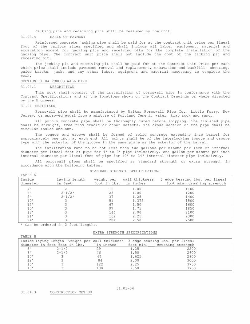
Jacking pits and receiving pits shall be measured by the unit.
31.03.4 BASIS OF PAYMENT
Reinforced concrete jacking pipe shall be paid for at the contract unit price per lineal foot of the various sizes specified and shall include all labor, equipment, material and excavation except for jacking pits and receiving pits for the complete installation of the jacking pipe. The contract unit price shall not include the cost of the jacking pit and receiving pit.
The jacking pit and receiving pit shall be paid for at the Contract Unit Price per each which price shall include pavement removal and replacement, excavation and backfill, sheeting, guide tracks, jacks and any other labor, equipment and material necessary to complete the work.
SECTION 31.04 POROUS WALL PIPE
31.04.1 DESCRIPTION
This work shall consist of the installation of poroswall pipe in conformance with the Contract Specifications and at the locations shown on the Contract Drawings or where directed by the Engineer.
31.04 MATERIALS
Poroswall pipe shall be manufactured by Walker Poroswall Pipe Co., Little Ferry, New Jersey, or approved equal from a mixture of Portland Cement, water, trap rock and sand.
All porous concrete pipe shall be thoroughly cured before shipping. The finished pipe shall be straight, free from cracks or other defects. The cross section of the pipe shall be circular inside and out.
The tongue and groove shall be formed of solid concrete extending into barrel for approximately one inch at each end. All joints shall be of the interlocking tongue and groove type with the exterior of the groove in the same plane as the exterior of the barrel.
The infiltration rate to be not less than two gallons per minute per inch of internal diameter per lineal foot of pipe for 4" to 8" pipe inclusively, one gallon per minute per inch internal diameter per lineal foot of pipe for 10" to 24" internal diameter pipe inclusively.
All poroswall pipes shall be specified as standard strength or extra strength in accordance with the following tables.
STANDARD STRENGTH SPECIFICATIONS TABLE A Inside laying length weight per wall thickness 3 edge bearing lbs. per lineal diameter in feet foot in lbs. in inches foot min. crushing strength
4" 2 16 1.00 1100 6" 2-1/2* 23 1.00 1200 8" 2-1/2* 37 1.25 1400 10" 3 51 1.375 1500 12" 3 67 1.50 1600 15" 3 97 1.75 1850 18" 3 144 2.00 2100 21" 3 162 2.25 2300 24" 3 224 2.50 2500 * Can be ordered in 2 foot lengths.
EXTRA STRENGTH SPECIFICATIONS TABLE B Inside laying length weight per wall thickness 3 edge bearing lbs. per lineal diameter in feet foot in lbs. in inches foot min.___ crushing strength 6" 2-1/2 29 1.25 2200 8" 2-1/2 46 1.50 2600 10" 3 64 1.625 2800 12" 3 84 2.00 3000 15" 3 122 2.25 3750 18" 3 180 2.50 3750
31.01-04 31.04.3 CONSTRUCTION METHOD
Poroswall pipe shall be of the size and strength as indicated on the Contract Drawings or ordered by the Engineer or specified elsewhere in the Contract Documents. Pipe shall be laid as indicated on the Contract Drawings or otherwise directed. All pipe when in place, shall be precisely true to the line and grade specified. Unless otherwise directed, pipe shall be laid up grade without breaks in the line.
31.04.4 METHOD OF MEASUREMENT
Measurement for all poroswall pipes shall be made by the Engineer. The actual length in lineal feet of pipe laid and accepted in place only shall be measured.
31.04.5 BASIS OF PAYMENT
Payment for all poroswall pipes laid and measured for payment will be paid for at the contract unit price for each respective size and strength. Said payment shall include the cost of the pipe, the placement of the pipe, and all labor, material and equipment incidental to the installation of the pipe.
No extra payment shall be made for elbows, tees, Y's and other fittings.
SECTION 31.07 SEEPAGE PIT
31.07.1 DESCRIPTION
Work under this item shall consist of furnishing all labor, equipment and materials necessary to construct seepage pits, complete including excavation, and conforming to the location, lines, grades, dimensions and details shown on the contract plans and in accordance with these specifications.
31.07.2 MATERIALS
Steps to be aluminum drop-front type as manufactured by Alcoa Aluminum Company or approved equal.
Brick shall conform to Section 2.08 of these specifications.
Concrete and reinforcing steel shall conform to Section 2.07 of these specifications using Class B-AE concrete.
Concrete blocks shall conform to Section 2.14 of these specifications and shall be of the type and size detailed on the Contract plans. Blocks shall be of heavy weight concrete.
Broken stone shall conform to Section 2.02.01 of these specifications and shall be the size shown on the plans.
Cobbles shall be hard and durable and of the size and shape acceptable to the Engineer.
Mortar shall conform to Section 2.09 of these specifications.
31.07.3 CONSTRUCTION METHODS
Vertical walls shall be constructed upward without mortar joints to within two courses of block below the bottom of the corbel. The remaining portion of the wall shall be constructed with the use of mortared joints. Mortared joints shall be used to secure steps.
Heavy weight concrete blocks used in the unmortared walls shall be laid close with no conscious attempt made to provide openings between the units. The uneven edge along with openings in the cored block will provide the space necessary for seepage into the surrounding soil.
It is particularly important that proper precautions be taken to prevent the sidewalls from collapsing while the pit is being constructed.
A twelve-inch filter of cobbles and broken stone shall be constructed as detailed on the plans, only after the masonry portion of the seepage pit has been inspected and approved by the Engineer.
The mortared portion of the seepage pit shall be constructed in accordance with the Connecticut State Highway Department Standard Specifications, Form 809, Section 5.07, where applicable.
31.01-05 Backfilling shall be done using suitable excavated material, which is approved by the Engineer. Where excavated material is not suitable the Engineer may order backfilling with
"Gravel Fill". During excavation, the Contractor must sort the suitable from the unsuitable material when practical, as directed by the Engineer.
Backfilling shall be in accordance with Section 20.02 of these specifications, where applicable. 31.07.4 METHOD OF MEASUREMENT The quantity of seepage pits to be measured for payment shall be the number of seepage pits incorporated in the work, complete as shown, specified or required. 31.07.5 BASIS OF PAYMENT Seepage pits will be paid for at the contract unit price each for "Seepage Pit" conforming to the details shown on the contract drawings, complete in place, which price shall include all materials, equipment, tools and labor, including frame and cover all as shown on the plans. Excavation, backfilling using excavated material, sheeting, shoring, bracing, cobbles, broken stone, steps, brick, block, etc., necessary to construct the seepage pit will not be measured or paid for directly but such cost shall be included in the cost of the item "Seepage Pit". "Gravel Fill" shall be used for backfilling and "Rock Excavation" performed only when ordered in writing by the Engineer, in which case these items shall be constructed, measured and paid for as specified under "Gravel Fill" (Section 40.02) and Trench Excavation in Rock (Section 20.02), respectively, of these specifications.
31.01-06
SECTION 31.05 V-LOCS
30.05.1 DESCRIPTION Traffic signs are to be anchored by the use of V-LOCS at the location shown on the plans or as directed by the Engineer. 30.05.2 MATERIALS The materials to be used in the construction shall be those indicated on the plans or ordered by the Engineer and conforming to these specifications.
These items are as specified for 23-VR1, as manufactured by Foresight Products, Inc. as shown on the plans.
30.05.3 CONSTRUCTION METHODS V-LOCS shall be embedded in the sidewalk as shown on the plans at a distance from the curb indicated on the plans and slanted in such a way that when the sign support pipe is installed; the sign shall be in erect position facing the traffic. 30.05.4 METHOD OF MEASUREMENT The quantity of V-LOCS be measured for payment shall be the number of V-LOCS, furnished and incorporated in the work complete as shown, specified or required. 30.05.5 BASIS OF PAYMENT The Contract Price shall be a unit price for each, and shall cover the cost of all labor, materials, plant, equipment and insurance required or necessary to construct the V-LOCS complete, and do all work incidental thereto, all in accordance with the plans and specifications and as directed by the Engineer.

31-05-1
SECTION 40.01 BROKEN STONE FILL
40.01.1 DESCRIPTION This material shall be used to replace unsuitable foundation material, and elsewhere as indicated on the plans, required by the specifications or as ordered by the Engineer. It shall consist of broken stone conforming to the requirements of these specifications. 40.01.2 MATERIALS Broken Stone shall conform to Section 2.02 for the applicable size shown on the plans or directed by the Engineer. 40.01.3 CONSTRUCTION METHODS Where broken stone is used for foundation or to replace unsuitable material, it shall be deposited in layers not over 8 inches thick and each layer shall be thoroughly compacted before the addition of other layers. The surface shall be carefully brought to grade and compacted as shown on the plans and as directed by the Engineer. 40.01.4 METHOD OF MEASUREMENT Broken Stone Fill will be measured by the Engineer in place after compaction within the payment lines shown on the plans or as established by the Engineer. 40.01.5 BASIS OF PAYMENT The work will be paid for at the Contract Unit Price per cubic yard for "Broken Stone Fill" for the applicable gradation specified complete in place, which price shall include all materials, tools, equipment, labor and incidental work for providing and placing the broken stone as specified above.
40.01-1
SECTION 40.02GRAVEL FILL
40.02.1 DESCRIPTION This material shall be used to replace unsuitable foundation material, and elsewhere as indicated on the plans, required by the specifications or as ordered by the Engineer. It shall consist of gravel conforming to the requirements of these specifications. 40.02.2 MATERIALS Gravel shall conform to Section 2.02.2 of these specifications. 40.02.3 CONSTRUCTION METHODS Here gravel is used for foundation or to replace unsuitable material, it shall be deposited in layers not over 6 inches thick and each layer shall be thoroughly compacted before the addition of other layers. The surface shall be carefully brought to grade as shown on the plans and compacted as directed by the Engineer. When noted in the plans or directed by the Engineer the Contractor shall employ vibrating compaction equipment to obtain maximum density of the gravel fill. Moisture shall be controlled as directed by the Engineer. 40.02.4 METHOD OF MEASUREMENT Gravel Fill will be measured by the Engineer in place after compaction within the payment lines shown on the plans or as established by the Engineer. 40.02.5 BASIS OF PAYMENT The work will be paid for at the Contract Unit Price per cubic yard for "Gravel Fill" complete in place, which price shall include all materials, tools, equipment, labor and incidental work for providing and placing the gravel as specified above.
40.02-1
SECTION 40.03 TEMPORARY PAVEMENT REPLACEMENT
40.03.1 DESCRIPTION Pavement which has been removed for the installation of sewers and sewer appurtenances or other underground installations shall be replaced immediately upon the completion of the trench backfilling and compaction with temporary pavement of the materials and in accordance with the limits and to the dimensions shown on the contract drawings, specified herein, or as directed by the Engineer. 40.03.2 MATERIALS a. Bank Run Gravel Base- shall conform to Section 2.02.2 of these
specifications where applicable. b. Bituminous Concrete - shall conform to Section 2.03 of these
specifications for base course. 40.03.3 CONSTRUCTION METHODS Temporary pavement replacement shall consist of a three course base, nineteen (19) inches thick after compaction of bank run gravel placed in layers not over six inches in depth and each layer thoroughly compacted before additional layers are placed, and a surface course of one and one-half (1-1/2) inches of bituminous concrete, placed in accordance with Section 40.12. 40.03.4 METHOD OF MEASUREMENT Measurement for payment for temporary pavement replacement shall be made by the Engineer in square yards within the limits and to the dimensions shown on the contract drawings, or as determined by the Engineer. 40.03.5 BASIS OF PAYMENT Payment for temporary pavement replacement will be made at the Contract unit price, per square yard, for "Temporary Pavement Replacement" as measured and approved for payment by the Engineer and shall include the cost of all labor, equipment, and material necessary for and incidental to the temporary pavement replacement including gravel, compaction, and maintenance. The Contractor shall maintain, at no additional expense to the City and to the satisfaction of the Engineer, the temporary pavement at all times until the permanent pavement replacement is complete. 40.03.6 NOTICE TO CONTRACTOR When payment is authorized under this Section or when plans specifically show Permanent Pavement Replacement, or when it is directed by the Engineer that payment will be made under this Section; then no payments will be made under Sections 40.02, 40.10, 40.12, 40.13, 40.14, or 40.17.
40-03-1
SECTION 40.04 PERMANENT PAVEMENT REPLACEMENT - WITH BITUMINOUS MACADAM BASE
40.04.1 DESCRIPTION Upon the apparent ending of the settlement of the excavation or when directed by the Engineer, the temporary pavement shall be removed and replaced by permanent pavement with bituminous macadam base where the original pavement had other than concrete base or when directed by the Engineer.
40.04.2 MATERIALS
a. Bank Run Gravel - Shall conform to Section 2.02 of these contract documents.
b. Broken Stone Base - shall conform to Section 2.02 for 2" size.
c. Bituminous Macadam Base - shall conform to Section 40.15 of these specifications.
d. Bituminous Concrete Base Course- shall conform to Section 40.12 of these specifications.
e. Bituminous Concrete Surface - shall conform to Section 40.13 of these specifications.
40.04.3 CONSTRUCTION METHODS
The base shall consist of a one course foundation constructed on the prepared sub-base in accordance with these specifications and in conformity with the lines, compacted thickness and typical cross-section as shown on the contract drawings. The grade of the broken stone base shall be coincidental to the undisturbed existing pavement. The bituminous macadam base shall consist of two three-inch courses of premix bituminous macadam base constructed on a prepared broken stone base course in accordance with these specifications and in conformity with the line, compacted thickness and typical cross-section as shown on the contract drawings. The grades shall be coincidental to that of the undisturbed existing pavement.
The bituminous concrete base course shall be constructed on the prepared bituminous macadam base in accordance with these specifications and in conformity with the line, compacted thickness and typical cross-section as shown on the contract drawings. The grade shall be coincidental with that of the undisturbed existing pavement.
Prior to placing the surface course all exposed edges of existing pavement will be coated with RC-2 or other approved bitumen to bond the existing to the new work.
The bituminous concrete surface course shall be constructed on the prepared bituminous concrete base course in accordance with these specifications and in conformity with the lines, compacted thickness and typical cross-section as shown on the contract drawings. The grade shall be coincidental with the undisturbed existing pavement.
Construction methods shall conform to the following sections of these specifications:
1. Broken Stone Base - Section 40.14.3 2. Bituminous Macadam Base - Section 40.17.3 3. Bituminous Concrete Base Course - Section 40.12.3 4. Bituminous Concrete Surface - Section 40.13.3
40.04.4 METHOD OF MEASUREMENT
Measurement for payment for permanent pavement replacement with bituminous macadam base shall be made by the Engineer in accordance with the limits and to the dimensions shown on the contract drawings, or as determined by the Engineer.
40.04.5 BASIS OF PAYMENT
Payment for permanent pavement replacement with bituminous macadam base will be made at the contract unit price, per square yard, for "Permanent Pavement Replacement with Bituminous Macadam Base". Said payment shall include the cost of all labor, equipment and materials necessary for and incidental to the construction of the permanent pavement replacement including adjustment of the sub-base, broken stone base, bituminous macadam base, bituminous concrete base course, bituminous concrete surface course.
40.04.6 NOTICE TO CONTRACTOR
When payment is authorized under this Section or when plans specifically show Permanent Pavement Replacement, or when it is directed by the Engineer that payment will be made under this Section; then no payments will be made under Sections 40.02, 40.10, 40.12, 40.13, 40.14, or 40.17. Permanent pavement shall not be placed on any trench prior to 60 days after backfilling or before all settlement has taken place. In any event, the Engineer's authorization shall be secured before placing permanent pavement. During the period between November 1 and April 15 inclusive no permanent pavement will be placed without written authorization of the Engineer.
SECTION 40.05 PERMANENT PAVEMENT REPLACEMENT - WITH CONCRETE BASE
40.05.1 DESCRIPTION
Upon the apparent ending of the settlement of the excavation or as directed by the Engineer, the temporary pavement shall be removed and replaced by permanent pavement with a concrete base where the original pavement had a concrete base or as directed by the Engineer.
40.05.2 MATERIALS
a. Bank Run Gravel- shall conform to Section 2.02.2 of these specifications.
b. Concrete - shall be concrete Class "B" AE as specified in Section 2.07 of these contract specifications.
c. Bituminous Concrete - shall conform to Section 2.03 of these specifications.
40.05.3 CONSTRUCTION METHODS
The Contractor shall adjust the existing sub-base of the temporary pavement by either adding or removing gravel until the sub-base is at a grade coincidental to that of the undisturbed existing pavement subbase.
Concrete base shall be constructed on the prepared base to the form and dimensions shown on the contract drawings and in accordance with these specifications. There shall be no reinforcing in the base and joints will not be required.
Construction methods for the concrete base shall conform to Section 40.16 of these specifications.
The bituminous concrete pavement shall be constructed on the base in accordance with these specifications and in conformity with the lines, compacted thickness, and typical cross-section shown on the contract drawings. The grade shall be coincidental with the undisturbed existing pavement.
Construction methods for bituminous concrete pavement shall conform to Section 40.12.3 and 40.13.3 of these specifications.
40.05.4 METHOD OF MEASUREMENT
Measurement for payment shall be made by the Engineer in accordance with the limits and to the dimensions shown on Contract Drawings, or as determined by the Engineer.
40.05.5 BASIS OF PAYMENT
Payment for permanent pavement replacement with concrete base will be made at the contract unit price, per square yard, for "Permanent Pavement Replacement with Concrete Base". Said payment shall include the cost of all labor, equipment and materials necessary for and incidental to the construction of the permanent pavement replacement with concrete base including the adjustment of the subbase, concrete base and the bituminous concrete pavement.
40.05.6 NOTICE TO CONTRACTOR
When payment is authorized under this Section or when plans specifically show Permanent Pavement Replacement, or when it is directed by the Engineer that payment will be made under this Section; then no payments will be made under Sections 40.2, 40.10, 40.12, 40.13, 40.14, 40.15, or 40.16.
Permanent pavement shall not be placed on any trench prior to 60 days after backfilling or before all settlement has taken place. In any event the Engineer's authorization shall be secured before placing permanent pavement. During the period between November 1 and April 15 inclusive, no permanent pavement will be placed without written authorization of the Engineer.
Note to Contractor
The Engineer may order the use of High Early Strength cement in place of Type IIa as specified in Section 2.07 of the Material Section of these specifications. The use of High Early cement shall be at no additional expense to the City of New Haven.
40.05-01
SECTION 40.06 CONCRETE CURBING
40.06.1 DESCRIPTION
This item shall consist of constructing concrete curbing in the locations and to the dimensions and details as shown on the contract plans or as directed by the Engineer all in accordance with these specifications.
40.06.2 MATERIALS
Concrete - shall be concrete Class "B" AE and shall conform to Section 2.07 of these contract specifications.
Bituminous joint filler shall conform to Section 2.15 for the type shown on the plans.
40.06.3 CONSTRUCTION METHODS
Excavation shall be made to dimensions sufficient to permit the setting of forms. The material underlying concrete curbs shall be satisfactory and thoroughly compacted. Dimension shall be shown on the plans.
Forms shall either be of metal of sufficient thickness, but not less than one-eighth (1/8) inch to satisfactorily resist distortion when fastened together and secured in place, or be of acceptable planned and matched lumber of sufficient thickness to resist distortion, rigidly held in position and of such construction that a smooth surface will be provided. Forms shall have suitable metal dividing plates approximately three-sixteenth (3/16) inch thick of a depth not less than that of the curb, be properly located with tops at grade and be left in place until the concrete has hardened. Forms for curved sections shall be of steel or plywood shaped to conform to the required radius and adequately braced.
Concrete curb shall be built in independent sections ten (10) feet long except as otherwise specified and shall have smooth plane end separated by one-quarter (1/4) inch joints. The concrete shall be deposited and compacted as specified elsewhere.
The top and the front face for ten (10) inches down from the top shall be finished by troweling and finally by using wooden floats. Upon the removal of the forms the exposed faces shall be rubbed to a smooth and uniform surface. The color of the finished curb shall be uniform.
Backfilling shall follow the removal of the forms as soon as practicable and shall be of clean earth or other approved material satisfactorily compacted.
Concrete curbs shall be carefully protected against injury from rain, frost, the drying effects of the sun and wind, traffic and other causes by means of suitable guards and covering and be cured in accordance with the specifications of this contract.
40.06.4 METHOD OF MEASUREMENT
This work will be measured for payment as the actual number of linear feet of concrete curing completed and accepted by the Engineer.
40.06.5 BASIS OF PAYMENT Payment for this work will be made at the contract unit price per linear foot for "Concrete Curbing" complete in place, which price shall include all materials, equipment, tools and labor incidental thereto; all excavation, backfilling, disposal of surplus material and the cost of maintaining the curbs in good condition.
The Contractor's attention is called to the following:
Where the contract plans call for replacement of concrete curbing, said work shall be done in according to these contract specifications. Payment for this work shall be at the contract unit price per linear foot for "Concrete Curbing" and shall include all materials, equipment, tools and labor incidental thereto; also all excavation, backfilling; also repaving, replacement of sidewalk, loaming and seeding of the trenched area, disposal of surplus material and maintaining the curbs in good condition as specified in this section.
40.06-01
SECTION 40.07 CONCRETE SIDEWALKS
40.07.1 DESCRIPTION This item shall consist of concrete sidewalks, either replacement or new constructed on a gravel base in the
locations and to the dimensions and details as shown on the Contract Plans or as directed by the Engineer in accordance with these Specifications.
40.07.2 MATERIALS
Concrete shall be Class “B” AE and shall conform to Section 2.07 of these Contract Specifications.
Gravel shall conform to Section 2.02.2 of these Contract Specifications.
Bituminous joint filler shall conform to Section 2.15.1 of these Specifications or as shown on the plans.
40.07.3 CONSTRUCTION METHODS
Where the sidewalk is removed or disturbed, that portion of said sidewalk removed or disturbed shall be replaced. Such replacement shall match the existing sidewalk including the base as nearly as is practicable.
When ordered by the Engineer existing sidewalk pavements that are to remain shall be cut with a masonry saw along the lines of the limits of sidewalk pavement that is to be removed and replaced at no additional expense. Excavation shall include the removal of any existing sidewalk and shall be made to the required depth below the finished grade as shown on the Plans. All soft and yielding material shall be removed and replaced with suitable material properly compacted.
The gravel base shall be placed in layers not to exceed 6 inches in depth. After compaction the surface shall be the specified depth below the finished grade of the walk. The base shall be wetted and rolled or tamped after spreading each layer.
pressure of the concrete. If wood, they shall be of 2 inch surfaced plank except that at sharp curves thinner material may be used. If of metal, they shall be of approved section and shall have a flat surface on the top. The base of metal forms shall be 2/3 the height. Forms shall be of a depth equal to the depth of the sidewalk. Forms shall be securely staked, braced and held to the required line and grade. T Forms shall be of metal or wood, straight, free from warp and of sufficient strength to resist springing from the hey shall be sufficiently tight to prevent leakage of mortar. All forms shall be clean and oiled before concrete is placed. Suitable forms shall be used at the end of all walks and at the end of each day’s pour. Concrete shall be placed in accordance with Section 2.07 of these Contract Specifications, where applicable. Forms shall not be removed until the concrete has had at least 12 hours to set.
The surface of the concrete shall be finished with a wood float. The outside edges and all joints shall be edged with a ¼” radius edging tool. Slabs shall be divided into two or more sections by forming dummy joints with a jointing tool, to a proper condition and frequently renewed to insure a minimum depth of 3/8” at all times.
Expansion joints shall be placed as shown on the Plans or as directed.
The sides of the walk shall be backfilled with suitable material compacted and finished flush with the top of the walk.
It shall be the Contractor’s responsibility to see that all existing street signs, parking signs, curb boxes and parking meters are protected during construction and replaced at their original location, unless otherwise directed. Curb box shall be reset to the new sidewalk grade.
40.07-01
Concrete shall be cured in accordance with Section 2.07 of these Contract Specifications and the following requirements:
1. Under Normal Weather Conditions: the contractor shall have the option upon approval of the Engineer of using any of the following methods:
a. Moist Curing: Immediately after finishing, the concrete surface shall be protected by careful covering with moist cotton mats. The mats shall be kept saturated for a period of 7 days. b. Cover Sheet Curing: As soon as practicable after finishing the concrete surface, waterproof paper or white polyethylene sheeting shall be carefully placed so that adjoining sheets shall overlap at least 12 inches, and the lap shall be securely weighted down to form a closed joint. Upon removal of the forms, the exposed edges shall be completely covered. Cover sheets shall remain in place for a period of 7 days. Reused cover sheets shall be in good condition in the opinion of the Engineer. If hair checking develops before the cover sheets can be placed, moist curing mats shall be used for the initial 24 hours of the curing period, and cover sheets placed for the remaining 6 days. C. Liquid Membrane-Forming Compound: Compound shall be applied immediately following the disappearance of water sheen following final finishing and before any marked dehydration of the concrete or surface checking occurs. The compound shall be applied by an approved pressure sprayer provided with an agitator device to prevent settlement.
The compound shall be applied in a continuous, uniform film at not less than one gallon per 200 square feet.
If the forms are removed before the 7 days curing period, the exposed sides shall be pointed, cleaned and covered with the compound.
Treated areas that become damaged by rain or wear shall be retreated to the original requirements.
2. Cold Weather Protection: When the Engineer directs the Contractor to provide protection against low temperatures during the curing period, the Contractor shall use one of the above curing methods and in addition, shall place a layer of hay or straw 8 inches thick over the entire surface upon which shall be placed another layer of mats or cover sheets. The edges of the covers shall be firmly fastened in place. This protective covering shall be maintained in good condition by the Contractor for a minimum of 7 days or for such time as the Engineer may direct.
40.07.4 METHOD OF MEASUREMENT This work will be measured for payment as concrete sidewalk and will be measured by the Engineer for the actual number of square yards completed and accepted.
40.07.5 BASIS OF PAYMENT
Concrete sidewalk will be paid for at the contract unit price, per square yard, for “Concrete Sidewalk”, complete in place, which price shall include all excavation below the finished grade of the sidewalk, saw cutting, backfilling, disposal of surplus material, gravel base, equipment, tools, materials and labor incidental thereto.
Note to Contractor
The Engineer may order the use of Type III High Early Strength cement in place of Type IIa as specified in 2.07 of the Material Section of these Specifications. The use of High Early cement shall be at no additional expense to the City of New Haven.
40-07-2
SPECIAL PROVISIONS
TEXTURED CONCRETE SIDEWALK
A. Description
The work included under this section consists of the construction of Colored Textured Concrete Sidewalks either replacement or new, constructed on a gravel base in the locations and the dimensions and details as shown on the Contract Plans or as directed by the Engineer in accordance with these specifications.
B. MATERIALS
Concrete shall be class "B”AE and shall conform to Section 2.07 of the Contract Specifications. Concrete 28 day compressive strength shall be 4,000 psi.
Textured Paving System shall be "Stentex concrete Paving System" as manufactured by Coloration Systems, Inc. (1-800-848-9982) or approved equal. Provide manufacturer’s recommended color hardener release agent and solvent sealer. Color for concrete shall be light gray or as approved by the Engineer.
Bituminous joint filler shall conform to Section 2.15.1 of these Specifications or as shown on the plans.
C. CONSTRUCTION METHODS
Where the sidewalk is removed or disturbed, that portion of said sidewalk removed or disturbed shall be replaced. Such replacement shall match the existing sidewalk including the base as nearly as practicable. Where new textured concrete sidewalk is to be constructed, gravel base per the requirements and details for concrete sidewalk shall be installed on a prepared subgrade.
When ordered by the Engineer existing sidewalk pavements that are to remain shall be cut with a masonry saw along the lines of the limits of sidewalk pavement that is to be removed and replaced at no additional expense.
Excavation shall include the removal of any existing sidewalk and shall be made to the required depth below the finished grade as shown on the plans. All soft and yielding material shall be removed and replaced with suitable material, properly compacted.
The gravel base shall be placed in layers not to exceed 6 inches in depth. After compaction the surface shall be the specified depth below the finished grade of the walk. The base shall be wetted and rolled or tamped after spreading each layer. Forms shall be of metal or wood, straight, free from warp and of sufficient strength to resist springing from the pressure of the concrete. If wood, they shall be of 2 inch surfaced plank except that at sharp curves thinner material may be used. If of metal, they shall be of approved section and shall have a flat surface on the top. The base of metal forms shall be 2/3 the height. Forms shall be of a depth equal to the depth of the sidewalk. Forms shall be securely staked, braced and held to the required line and grade. They shall be sufficiently tight to prevent leakage of mortar. All forms shall be clean and oiled before concrete is placed. Suitable forms shall be used at the end of each day’s pour. Concrete shall be placed in accordance with section 2.07 of these Contract Specifications, where applicable. Forms shall not be removed until the concrete had had at least 12 hours to set. Expansion joints shall be placed as shown on the plans or as directed.
The sides of the walk shall be backfilled with suitable materials compacted and finished flush with the top of the walk.
It shall be the Contractor’s responsibility to see that all existing street signs, parking signs, curb boxes and parking meters are protected during construction and replaced at their original location if indicated on the Contract Drawings, unless otherwise directed. Curb boxes shall be reset to the new sidewalk grade.
Concrete shall be installed and cured in accordance with Section 2.07 of these Contract Specifications and the following requirements:
1 1. Application: After Coloration System Color Hardener is applied and has been troweled, apply a light, uniform dusting a Coloration System Release Agent in a contrasting color, using the dry shake method. Care should be taken to
achieve uniform and total coverage of the area to be textured. The surface should never be troweled after the Release Agent has been applied. Imprinting tools or texture roller may be used at this time. After the concrete has reached its initial strength, (usually the following day), the surface may be swept and/or washed to remove the majority of excess Release Agent. Once the slab has reached initial cure, (seven or eight days), the surface may be pressure cleaned or scrubbed with a rotary floor machine to remove residual Release Agent. It is usually desirable to leave a certain amount of Release Agent in the imprint lines and textured areas. This will give the two-color effect, which is most desirable in texture imprinted concrete surfaces. Apply Coloration System Solvent Seal to aid in the retention of remaining Release Agent. This seal coat is recommended but not required. When sealed, the color of Release Agent will intensify.
The Contractor shall have an adequate number of platform tools at the job site to sufficiently cover the work area.
The Contractor shall also provide temporary bridging over the surface to be stenciled in order to avoid disturbance to wet concrete to be stenciled. The temporary bridging shall be adequate size, width, and strength so as not to impair the stamping process.
Tile pattern and color per the Contract Drawings or as otherwise approved by the Engineer shall be used.
2. Sealer Application: The surface should be cleaned of dirt, oil, gas, and all other foreign material and allowed to dry completely. Apply sealer uniformly with roller, brush, or spray equipment. When applying pigmented sealer, keep material stirred at all times to prevent settling of pigments. Avoid puddles and thick coats of sealer. Dry time will depend on ambient temperature and can vary from fifteen minutes to two hours. Over application may cause slipperiness when wet. Two thin coats are better than one thick coat. Allow two to four hours drying time prior to pedestrian traffic, and twenty-four hours drying time to vehicular traffic.
Use safety precautions as recommended by the manufacturer.
Only when surface is completely dry, apply sealer. Sealer shall be applied with an airless hand pump sprayer or long nap paint roller. Two light coats are required to allow for more uniform coverage. Protect concrete to prevent pedestrian or vehicle traffic damage until sealer is dry.
Cold weather protection: When the Engineer directs the Contractor to provide protection against low temperatures during the curing period, the contractor shall use one of approved curing methods and in addition, shall place a layer of hay or straw 8 inches thick over the entire surface upon which shall be placed another layer of mats or cover sheets. The edges of the covers shall be firmly fastened in place. This protective covering for a minimum of 7 days or for such time as the Engineer may direct.
D. METHOD OF MEASUREMENT
This work shall be measured for payment as stamped concrete sidewalk and will be measured by the Engineer as the actual number of square yard completed and accepted.
E. BASIS OF PAYMENT
Textured concrete sidewalk shall be paid for at the contract unit price, per square yard, for "Textured Concrete Sidewalk"' complete in place, which price shall include all excavation, backfilling, disposal of surplus material, gravel base, equipment, tools, materials and labor incidental thereto.
NOTE TO CONTRACTOR
The Engineer may order the use of Type III High Early Strength Cement in place of Type II. The use of High Early Strength Cement shall be at no additional expense to the City of New Haven.
2

SECTION 40.07M MENTORING/PROTÉGÉ PROGRAM
ITEM # 4 Clarification 40.07M.01 DESCRIPTION This item shall provide an opportunity for a minority-based firm to be able to expand their capabilities for construction and doing business with the City of New Haven. It is intended that the prime contractor select a minority firm of his/her choosing to work with his forces and work with supervisors in guiding the minority contractor to be successful in the area of sidewalk construction. This mentoring will also include training in project administration, cost estimating, contract compliance, quality control, and construction techniques for the management and staff working with this project. Reference is made to Section #328 "Concrete Sidewalk Mentoring Program" for further details. 40.07M.02 TRAINING REQUIREMENTS It is expected that the Contractor (Mentor) will provide the protégé with a knowledge base focused on doing sidewalk construction business within the city. General training shall consist of,
General Financing: including borrowing, payments, bookkeeping, overhead (fixed and variable) bonds, insurance, cash flow, etc.
Bid Estimating: including unit pricing, labor costs, materials, equipment cost, balancing bids, bid bonds, submission of bids.
Contract Administration: including certified payrolls, claims, change orders, daily reports, subcontractor management, city contract documents, requirements, interpretations, compliance reports. (Note: City will assist the contractor in conducting a seminar on city contract documents).
Construction Techniques: including subcontracted work, material usage, excavations, forming, concrete quality strength, testing materials, enforcement, finish work, expansion, cold weather pours, site protection, safety, clean-up, punch list work.
40.07M.03 TRAINING AND MONTORING PLAN The contractor shall submit a training and monitoring plan outlining in general terms over the duration of the contract. How the mentor will comply with the conditions set forth in this section or as described in the Special Conditions. 40.07M. 04 MENTORING & PROTEGE REPORTS The Contractor and Prot6g6 are required to complete progress reports indicating type of development, technical and administrative assistance provided. In addition the Commission on Equal Employment Opportunities for the city will conduct periodic and independent review of the program. It is the obligation of both the Contractor and Protege to complete said report which will be submitted on each Progress Payment Request. 40.07M05 BASIS OF MEASUREMENT AND PAYMENT The contractor shall be paid on the basis of a lump sum item prorated on a monthly basis over the duration of the contract. Progress will be measured based upon the plan submitted, training conducted and reports submitted. Inadequate compliance with scope of work provided under this item may delay payments due the contractor for such work. ITEM # 5 (See Attached "Agreement") pages 1 of 2 and 2 of 2.

This form is for information only. It shall be required by the City upon award of Contract.
AGREEMENT
CURB AND SIDEWALK MENTORING PROGRAM
Companies that are participating in the mentoring program must submit a signed mentor-protégé agreement for each mentor-protégé relationship for approval. Mentor-Protégé Program Agreement template- Agreement Information- 1- Period of Performance: Number of months: ______________________________________________________________________________________ 2- Mentor Firm Information: Name of person in charge: _________________________________________________________________________________ Address: _______________________________________________________________________________________________ Telephone, Fax: _________________________________________________________________________________________ 3. Protege Firm Information: Name of person in charge: ______________________________________________________________________ Address: ____________________________________________________________________________________ Telephone, fax: _______________________________________________________________________________ 4. Protege Eligibility: Provide a statement that the protege firm is eligible pursuant to the requirements in the contract documents on a separate sheet, and attach it to this Agreement. (To be titled Attachment A) 5. Developmental Assistance: Describe the developmental program for the protege firm specifying the type of assistance planned. Provide how this plan will address the protege's identified needs to enhance their ability to perform successfully under contracts or subcontracts with /for the City of New Haven. Use a separate sheet and attach it to this Agreement (To be titled Attachment B)
I of 2

6. Potential Subcontracts: The anticipated number, dollar value, and type of subcontracts to be awarded the protege firm consistent with the nature of mentor firm's business and the period of time over which they will be awarded. ________________________________________________________________________________________________________________________________________________________________________________________________________________________________________________________________________________________________________________________________________________________________ 7. Termination Procedure: (Mentor)
. The protege firm shall be furnished a written notice of the proposed termination, stating the specific reasons for such action at least 30 days in advance of the effective date of such termination.
. The protege firm shall have 15 days to respond to such notice of proposed termination and may rebut any findings believed to be erroneous and offer a solution.
. Upon prompt consideration of the protégé firms response, the mentor firm shall either withdraw the notice of proposed termination and continue the protege firms participation, or issue the notice of termination.
8. Termination Procedure (Protege): The protege firm shall notify the mentor firm in writing at least 30 days in advance of the protégé firms intent to voluntarily terminate the mentor-protege agreement. 9. Signature of both parties: Mentor and Protege are required to sign and date this Agreement. __________________________________________ ________________________
Mentor signature Date
__________________________________________ Title __________________________________________ _________________________ Protege signature Date __________________________________________ Title
2 of 2
SECTION 40.08 PRECAST CONCRETE CURBING
40.08.1 DESCRIPTION Work under this item shall include the construction and installation of precast concrete curbing as detailed and located on the contract plans and in accordance with these contract documents. 40.08.2 MATERIALS Materials for concrete shall conform to Section 2.07 of these specifications with the exception that the Contractor will use a white cement. Concrete shall be Class B with Type IIa Air entraining cement. Gravel shall conform to Section 2.02.2 of these specifications. 40.08.3 CONSTRUCTION METHODS The precast concrete curb shall be constructed as detailed on the contract plans at a central plant approved by the Engineer. Excavation shall consist of the removal of all materials including existing street pavements and basis, driveway pavements, sidewalk pavement, and curbs as required on the plans or as directed by the Engineer. Excavation shall be made to the bottom of the 6 inch gravel base below the curbing, the trench being sufficiently wide to permit thorough tamping. The base shall be compacted to a firm even surface and shall be approved by the Engineer. The curbing shall be set on edge and settled into place to the line and grade required, straight and true for the full depth. The joints of the concrete curbing shall be pointed with mortar for the full depth of the curbing. At approximately 50 feet intervals a 1/2 inch joint shall not be filled with mortar, but left free for expansion. The ends of the concrete curbing at driveways shall be cut at a bevel, or rounded, as directed by the Engineer. The trench for the concrete curbing shall be backfilled with approved material; the first layer to be 4 inches in depth, thoroughly rammed; the other layers to be not more than 6 inches in depth and thoroughly rammed until the trench is filled. 40.08.4 METHOD OF MEASUREMENT This work will be measured for payment by the actual number of linear feet of curbing installed and accepted by the Engineer. 40.08.5 BASIS OF PAYMENT Payment for this work will be made at the contract unit price per linear foot for "Precast Concrete Curbing" complete in place, which price shall include all materials, equipment, tools and labor necessary to complete the work. Said price shall also include the excavation, gravel base, and backfilling and the satisfactory removal of all surplus materials.
40.08-1
SECTION 40.09 GRANITE CURBING
40.09.1 DESCRIPTION This section shall include the installation of new granite curbing or the replacement of existing curbing with new granite curbing all in accordance with the requirements of the Contract Drawings and Specifications and as directed by the Engineer. 40.09.2 MATERIALS The stone for granite curbing shall be hard and durable granite of light color and uniform texture, neither stratified nor laminated. It shall be free from seams and evidence of weakening or disintegration and shall have good, smooth split faces. The Contractor shall be required to submit to the Engineer for his approval, a sample of the granite curbing he proposes to use and the name of the quarry from which it originates. After approval by the Engineer, no stone from other quarry sources shall be substituted on a project unless specifically approved by the Engineer. The top surface shall be pointed, peen hammered and sawed. The top 8 inches of the face shall be smooth quarry split and free from drill holes. The ends of all stones shall be square with the planes of the top and face, and so finished that when stones are placed end to end as closely as possible, no space more than 1/2 inch shall show in the joint for the full width of the top or the top 8 inches of the face. If sawed, the curbstone shall be thoroughly cleaned of any iron rust or iron particles. Straight curbing shall be furnished in lengths not less than 6 feet, except that for closures when no piece less than 4 feet in length will be allowed. 40.09.3 CONSTRUCTION METHODS Excavation shall consist of the removal of all materials, including existing street pavements and bases, driveway pavements, sidewalks, and curbs as required. Excavation shall be made to the bottom of the 6 inch gravel base below the curbing. The trench shall be made sufficiently wide to permit the subgrade or base to be thoroughly compacted to a firm, even surface to the satisfaction of the Engineer. Where new granite curb is installed along existing curb lines, the existing pavement shall be cut back 6 inches from the face of the curb to provide ample space to tamp the base. The curbing shall be set on edge and settled into place with a heavy wooden hand rammer, to the proper line and grade and straight and true for the full depth. The joints of the granite curbing shall be pointed for the full depth with mortar. Concrete shall then be placed at the joints as shown on the Contract Drawings. In the case where existing sidewalk abutting the back of the curbing is to remain, concrete shall only be placed at the face of the curbing joints. At approximately 50 foot intervals a 1/2 inch joint shall not be filled with mortar nor shall concrete be placed on either side of the joint to allow expansion.
40.09-1
The trench for the granite curbing shall be backfilled with approved material; the first layer to be 4 inches in depth thoroughly rammed, the other layers to be not more than 6 inches in depth and thoroughly rammed until the trench is filled. Where removal of existing pavement is required to provide working space, said pavement shall be replaced in kind unless otherwise directed by the Engineer. The limit of construction shall be 6 inches beyond the face of the proposed curbing. Upon completion of abutting sidewalks the Contractor shall clean the exposed top and face of the curbing of any excess concrete by brushing with a wire brush. 40.09.4 METHOD OF MEASUREMENT This work will be measured for payment by the actual number of linear feet of "Granite Curbing, Straight" or "Granite Curbing, Curved" installed and accepted. Measurement will be made by the Engineer along the face of curb. Curbing to be set on a radius of 100 feet or less will be measured for payment as " Granite Curbing, Curved". 40.09.5 BASIS OF PAYMENT Payment for this work will be made at the applicable contract unit price for "Granite Curbing, Straight" or "Granite Curbing, Curved", complete in place, which price shall include all materials, equipment, tools, gravel base, and labor necessary to complete the work. Said price shall include all excavation, necessary removal of existing pavements, bases and curbing, paving the trenched area, replacement of damaged or cut sidewalk or any portions thereof, loaming and seeding, the replacement of the above, and all incidental work necessary for the complete installation of granite curbing in accordance with the Contract Drawings and Specifications and as directed by the Engineer.
40.09-2
SECTION 40.10 ROLLED GRAVEL BASE
40.10.1 DESCRIPTION This base shall consist of a two-course foundation constructed on the prepared subgrade in accordance with these specifications and in conformity with the lines, grades, compacted thickness and typical cross section as shown on the plans. 40.10.2 MATERIALS The materials for this work shall consist of sound, tough, durable particles of gravel mixed with approved binding material and shall be free from thin or elongated pieces, lumps of clay, soil, loam or vegetable matter. The material may be bank-run or the binder may be added and incorporated by approved methods as herein specified and shall conform to Section 2.02.2 of these specifications. 40.10.3 CONSTRUCTION METHODS Materials for the bottom course shall be spread upon the prepared subgrade to such depth that this course will be of the specified depth after final compaction. If, after the material has been spread and shaped, it is found that additional binder is necessary, it shall be furnished and applied in an amount directed by the Engineer. Such binder material shall be carefully and uniformly incorporated with the material in place by scarifying, harrowing, brooming or other approved methods. The material shall then be shaped, wetted and rolled with a power roller weighing not less than ten tons, until thoroughly compacted. All areas of segregated coarse or fine material shall be corrected or removed and replaced with well graded material, as directed by the Engineer. The rolling and wetting shall be continued until all voids are filled and a slight wave of excess water and soil mortar forms a grout in front of the roller wheels after which this portion may be left to dry. The rate of rolling shall be such that one roller does not complete the rolling of more than 200 square yards in one hour or until the course is thoroughly compacted to a firm and uniform surface satisfactory to the Engineer. The material shall be rerolled and wetted on succeeding days. The rate and extent of the rolling and the quantity and method of applying water shall be as directed by the Engineer. All soft and yielding material in the base shall be removed and replaced with suitable material to the depth and extent necessary to insure a satisfactory foundation for pavement. Construction methods for the top course shall be the same as prescribed for the bottom course. 40.10.4 METHOD OF MEASUREMENT This work will be measured for payment by the cubic yard of accepted material placed to the compacted depth and horizontal length and width as shown on the plans or as ordered by the Engineer. 40.10.5 BASIS OF PAYMENT This work will be paid for at the contract unit price per cubic yard for "Rolled Gravel Base" complete in place which price shall include all materials, tools, equipment and labor incidental thereto. When no item for "Rolled Gravel Base" appears in the proposal, the cost of this work shall be included in the contract unit price for other items involved.
40.10-1
SECTION 40.11 REINFORCED CONCRETE DRIVEWAYS
40.11.1 DESCRIPTION Reinforced concrete driveways shall be made with Class "B" AE concrete with reinforcing steel at applicable locations, constructed on the prepared base in accordance with the dimensions and details shown on the plans or as ordered and in conformity with these contract documents. 40.11.2 MATERIALS 1. Concrete shall conform to the requirements for Class "B" AE concrete in
Section 2.07 of these specifications. 2. Reinforcing steel shall conform to the requirements of Section 2.11 of
these specifications and shall be the sizes shown on the drawings. 3. Bituminous joint filler shall conform to Section 2.15 of these
specifications for the type shown on the plans. 4. Gravel shall conform to Section 2.02.2 of these specifications. 40.11.3 CONSTRUCTION METHODS Construction methods will conform to the Connecticut Highway Department Standard Specifications Form 814, Article 4.01.03. 40.11.4 METHOD OF MEASUREMENT Measurement for payment of Reinforced Concrete Driveways shall be made by the actual number of square yards of pavement completed and accepted by the Engineer, in accordance with the limits and the dimensions shown on the contract drawings, or as determined by the Engineer. 40.11.5 BASIS OF PAYMENT Payment for this work will be made at the contract unit price per square yard for "Reinforced Concrete Driveway" as measured and approved for payment by the Engineer. Said payments shall include the cost of all labor, materials, tools, equipment and appliances incidental thereto, all excavation below the finish grade of the driveway, backfilling, disposal of surplus material and gravel base. Note to Contractor The Engineer may order the use of Type III High Early Strength cement in place of Type IIa as specified in 2.07 of the Material Section of these specifications. The use of High Early cement shall be at no additional expense to the City of New Haven.

40.11-1
SECTION 40.12 BITUMINOUS CONCRETE BASE COURSE
40.12.1 DESCRIPTION
This item shall consist of the construction of a bituminous concrete bottom course or of a bituminous concrete leveling course composed of a coarse aggregate and sand, uniformly mixed with asphalt cement. It shall be constructed on the prepared surface in accordance with these Specifications and in conformity with the line, grade, compacted thickness and typical cross section as shown on the Plans.
40.12.2 MATERIALS
The materials for this work shall conform to Section 2.03 of these Specifications.
40.12.3 CONSTRUCTION METHODS
The methods employed in performing the work and all equipment, tools, machinery and other plant used in handling material and executing any part of the work, shall be subject to the approval of the Engineer before the work is started and, whenever found unsatisfactory, shall be changed and improved as required by the Engineer. All equipment, tools, machinery and plant used must be maintained in a satisfactory working condition.
1. Forms
When forms are required they shall be of a depth not less than the total proposed thickness of the bituminous concrete course or courses. The forms shall be of an approved section, straight, free from warps and bends a all times and shall be of sufficient strength when properly set and staked to resist the pressure of any bituminous mixture, and to remain true to line and grade throughout the entire rolling and compaction operation. The forms shall have properly designed joints and not less than three stake pockets to each ten-foot length.
The forms shall be accurately set to line and to such grade that after screeding by the finishing machine, the weight of mixture per square yard required for each course will be secured. The forms shall be tightly jointed and sufficiently braced so as to prevent the mixture squeezing out under the rolling. The width between the forms shall not vary more than one-half inch from the indicated width of the pavement.
The alignment and grade of all forms set shall be approved before and immediately prior to the placing of any material against them. Forms shall be cleaned thoroughly and oiled each time they are used. They shall remain in place until after the placing and final compaction of the surface course or courses. Care shall be exercised in rolling so as not to displace the line and grade of the forms.
2. Placing of Mixture
Immediately before placing the mixture the base surface shall be cleaned by brooming or by other means acceptable to the Engineer. Unless the restriction is waived by written consent of the Engineer, the mixture shall be laid only during the period from April 15 to October 15, and further, these operations shall be carried on only when the surface is dry, the atmospheric temperature in the shade is at least 50 degrees F. and the weather is not foggy or rainy. The Engineer may, however, permit work of this character to continue when overtaken by sudden storms, up to the amount which may be in transit from the plant at the time, provided the mixture is within temperature limits specified.
41.12-01 Upon arrival, the mixture shall be dumped into the approved mechanical spreader and immediately spread and struck off to the full width required and to such appropriate loose depth for each successive course that when the work is completed the weight of the mixture required per square yard will be secured. Each course shall be struck off by the mechanical equipment. For use in striking off the bottom course the machine shall be equipped with easily adjustable strike-off plates. When approved in writing by the Engineer, the mechanical equipment may be omitted and spreading accomplished by hand.
In order to secure tight and well compacted longitudinal joints, the sequence of the bituminous concrete placing operations shall be subject to the control of the Engineer for all courses laid.
Before any rolling is started, the finished surface struck by the machine shall be checked, and inequalities adjusted, all "drippings" i.e., fat, sandy accumulations from the screed and all fat spots from any source, shall be removed and replaced by satisfactory material.
In areas where, on account of irregularities or unavoidable obstacles, the use of mechanical spreading and finishing equipment is impracticable, the mixture may be spread and screeded by hand.
When hand spreading is permitted by special provisions or when, because of any project conditions, it becomes necessary to spread by hand, the mixture, upon arrival, shall be dumped on approved steel dump sheets outside of the area on which it is to be spread and shall then be immediately distributed into place by means of suitable shovels and other tools and spread with metal lutes in a uniformly loose layer of such depth as will result in a completed pavement having the weight per square yard required. Any deviation from standard section shall be immediately remedied by placing additional material or removing surplus as directed. The Engineer may direct that other means of placing the material in addition to the metal lutes be used to insure a better control of the depths of material and the surface finish.
Contact surfaces of curbings, gutters, manholes, etc., shall be painted with a thin uniform coat of hot asphalt cement, or asphalt cement dissolved in naphtha, just before the material is placed against them. Where the bituminous material is spread on a concrete or an old bituminous base a uniform coat of asphalt shall be spread about one foot wide along each edge of the pavement to prevent water getting between the new pavement and the base. In any area where the new pavement is less than 1-1/2 inches thick and on steep grades the Engineer may order a very light web-like coating of hot asphalt paint applied to the old pavement. Care must be taken not to apply too heavy a coating or large blobs of asphalt paint.
The refueling of equipment in such position that fuel might be spilled on a bituminous concrete mixture already placed or to be placed, is prohibited.
Kerosene, gasoline or fuel oil for use in cleaning mechanical equipment or hand tools shall be stored well clear of areas paved or to be paved. Before any such equipment and tools are cleaned they shall be moved off the areas paved or to be paved, and they shall not be returned for use until after they have been allowed to dry.
3. Compaction
After the courses have been screeded as specified, each shall be rolled with power rollers as hereinafter provided. When the course spread has set sufficiently or come to the proper condition, it shall be rolled at such a speed as not to cause undue displacement or shoving.
Rollers to be used to compact the course shall be power driven rollers weighing not less than ten tons. If only one roller is used, it shall be a Tandem roller, a second roller may be of the three wheel type. The roller wheels shall be wet with only sufficient water to moisten the wheel surface.
40.12-02
Rolling shall begin at the sides and progress toward the center, uniformly lapping at least one-half the width of the compacting wheel of the roller. Alternate trips of the roller shall be terminated in stops at least three feet distant from any preceding stop. Other rolling procedure may be directed by the Engineer, as conditions may require. Rolling shall be discontinued if the surface shows signs of cracking and shall be continued later as directed.
The speed of the roller shall not exceed 3 miles per hour and shall at all times be slow enough to avoid displacement of the hot mixture. The rollers shall be in good condition. They shall be operated by experienced rollerman and must be kept in continuous operation as nearly as practicable in such manner that all parts of the pavement shall receive substantially equal compression.
In all places inaccessible to a roller, such as adjacent to curbs, headers, gutters, bridges, manholes, etc., the required compression shall be secured with tamps. Depressions which may develop before the completion of the rolling shall be remedied by adding new material to bring such depressions to a true surface. Should any depressions remain after the final compaction has been obtained, new material shall be added to form a true and even surface. All high spots, high joints and other defects shall be adjusted as directed by the Engineer.
4. Joints
Placing of the courses shall be as nearly continuous as possible and the roller shall pass over the unprotected end of the freshly laid mixture only when the laying of the course is discontinued or interrupted for an appreciable period, and joints shall be formed at such points. Where joints are to be formed the end of the freshly laid mixture shall be cut "square" with the pavement, slightly set up with the back of a metal lute and rolled at slow roller speed so as to cause as little feathering as possible. Before new material is laid the joint shall be cut back and a thin coating of hot asphalt applied to the joint. Care shall be taken to keep the asphalt paint off the surface of the pavement.
5. Surface Test of the Pavement
For the purpose of testing the finished surface, a standard template cut to the true cross section of the road shall at all time be available on the work, also a 10-foot straight edge.
The Contractor shall provide or designate some employee whose duty it is to use the straight edge and template in checking all rolled surfaces under the direction of the Engineer.
The finished pavement shall be such that it will not vary more than 1/4 inch from the template cut to the cross section of the road nor more than 1/4 inch from a 10-foot straight edge applied parallel to the center line of the pavement. Any irregularity of the surface exceeding the above limits shall be corrected. Depressions which may develop after the initial rolling shall be remedied by loosening the surface mixture laid, and adding new material to bring such depressions to a true surface. Such portions of the completed pavement as are defective in surface, compression or composition, or that do not comply with the requirements of the Specifications, shall be taken up, removed and replaced with suitable mixture properly laid in accordance with these Specifications at the expense of the Contractor.
6. Protection of the Work
Sections of the newly finished work shall be protected from traffic at least six hours, or until they have become properly hardened by cooling.
40.12-03 40.12.4 METHOD OF MEASUREMENT
This item will be measured for payment by the net weight in tons measured in the hauling vehicle. The Contractor is responsible for seeing that the City Inspector is given a weight slip showing the net weight of each load delivered on the job, and the same to be certified by the firm from which the Contractor purchased the product.
The total weight will be the summation of the weight slips of bituminous concrete actually incorporated in the work included under this item. The quantity to be included for payment for this work shall be subject to the following:
1. Determination of Thickness
Before final acceptance of the work or during the progress of the work, as the Engineer deems advisable, the thickness will be determined by measurements of cores taken at random points and the average of these core thicknesses will be considered as the average of four measurements along the sides of the core read to the nearest one-eighth inch.
2. Adjustment of Measured Weight
(a) No adjustment of the weight as determined from the weight slips will be made where the thickness does not exceed a tolerance of plus or minus one-half inch of the depth shown on the Plans.
(b) Where the thickness exceeds that shown on the plans by more than the allowable tolerance an amount equal to the computed weight of that material in excess of the Plan thickness plus one-half of an inch will be deducted from the weight determined from the weight slips.
(c) Where the thickness is less than that shown on the Plans by more than one-half of an inch and not more than three-quarters of an inch, there will be deducted an amount equal to 150 percent of the computed weight represented by that deficiency.
(d) Where the thickness is less than that shown on the Plans by more than three-quarters of an inch, the Contractor, with the permission of the Engineer, shall place a correction course not less than one inch in depth after compaction provided an acceptable grade and cross-section can be achieved. Where an acceptable grade and cross-section cannot be achieved through the above means, the Contractor shall reconstruct by cutting back and into the pavement having no more than three-quarters of an inch deficiency in thickness a sufficient distance to permit the placement of an acceptable depth and place new material to achieve the proper depth, cross section and profile. These areas where a corrective course is placed or reconstruction of the pavement is performed, will be re-cored and re-measured again as though originally constructed; no compensation will be made to the Contractor for materials removed, their removal or disposal or for restoration of affected supporting base or adjacent construction.
(e) An adjustment in quantity will be made in the bituminous concrete place beyond the horizontal limits indicated on the plans by deducting the computed weight of that material extending more than three inches beyond the horizontal Plan dimensions.
3. Computed Weight
The computed weight for purposes of determining deductions from the total weight indicated by weight slips will be computed on the basis of 110 pounds per square yard per inch of thickness.
40.12.5 BASIS OF PAYMENT
This work shall be paid for at the contract unit price per ton for "Bituminous Concrete Base Course", completed and accepted in place, which price shall include all materials, equipment, tools, labor and work incidental thereto.

40.12-04
SECTION 40.13 BITUMINOUS CONCRETE SURFACE COURSE
40.13.1 DESCRIPTION
This pavement shall consist of dense graded bituminous concrete to be constructed on a prepared bituminous concrete binder course in accordance with these Specifications and in conformity with the lines, grades and typical cross section shown on the Plans.
40.13.2 MATERIALS
The materials for this work shall conform to Section 2.03 of these Specifications.
40.13.3 CONSTRUCTION METHODS
The methods employed in performing the work and all equipment, tools, machinery and other plant used in handling material and executing any part of the work shall be subject to the approval of the Engineer before the work is started, and whenever found unsatisfactory, shall be changed and improved as required by the Engineer. All equipment, tools, machinery and plant used must be maintained in a satisfactory working condition.
1. Forms
This shall conform to the requirements of Article 40.12.3-1.
2. Placing of Mixture
This shall conform to the requirements of Article 40.12.3-2.
3. Compaction
This material shall be compacted in accordance with the requirements of article 40.12.3-3.
4. Placing Mineral Filler
After final rolling and checking of the bituminous surface, the Contractor shall dust the surface with a light coat of mineral filler if requested by the Engineer.
5. Joints
This work shall conform to the requirements of Article 40.12.3-4.
6. Surface Test of the Pavement
For the purpose of testing the finished surface, a standard template cut to the true cross section of the road shall at all times be available on the work, also a 10-foot straight edge. The Contractor shall provide or designate some employee whose duty it is to use the straight edge and template in checking all rolled surfaces under the direction of the Engineer. The finished pavement shall be such that it will not vary more than 1/4 inch from the template cut to the cross section of the road nor more than 1/4 inch from a 10-foot straight edge applied parallel to the center line of the pavement. Any irregularity of the surface exceeding the above limits shall be corrected.
40.13-01
Depressions which may develop after the initial rolling shall be remedied by loosening the surface mixture laid, and adding new material to bring such depressions to a true surface. Such portions of the completed pavement as are defective in surface, compression or composition, or that do not comply with the requirements of the Specifications shall be taken up, removed and replaced with suitable mixture, properly laid in accordance with these Specifications at the expense of the Contractor.
7. Protection of the Work
This shall be done in accordance with the requirements of Article 40.12.3-6.
NOTICE TO CONTRACTOR
No payment will be authorized under this Section. All costs shall be included in the contract unit price for "Temporary Pavement Replacement" and "Permanent Pavement Replacement", per square yard complete.
8. Joints
This work shall conform to the requirements of Article 40.12.3-4.
9. Surface Test of the Pavement
For the purpose of testing the finished surface, a standard template Cut to the true cross section of the road shall at all times be available on the work, also a 10-foot straight edge.
The Contractor shall provide or designate some employee whose duty it is to use the straight edge and template in checking all rolled surfaces under the direction of the Engineer.
The finished pavement shall not vary more than 1/4 inch from the template cut to the cross section of the road nor more than 1/4 inch from a 10-foot straight edge applied parallel to the centerline of the pavement. Any irregularity of the surface exceeding the above limits shall be corrected. Depressions which may develop after the initial rolling shall be remedied by loosening the surface mixture laid, and adding new material to such depressions to a true surface. Such portions of the completed pavement as are defective in surface, compression or composition, or that do not comply with the requirements of the Specifications shall be taken up, removed and replaced with suitable mixture, properly laid in accordance with these Specifications at the expense of the Contractor.
10. Protection of the Work
This shall be done in accordance with the requirements of Article 40.12.3-6.
40.13.04 METHOD OF MEASUREMENT
This work will be measured for payment in the same manner outlined in Section 40.12.4 of these Contract Specifications.
40.12.05 BASIS OF PAYMENT
This work shall be paid for at the contract unit price per ton for "Bituminous Concrete Surface Course", complete in place, which price shall include all materials, tools, equipment, and labor incidental thereto.
40.13-02
SECTION 40.14 BROKEN STONE BASE
40.14.1 DESCRIPTION
The stone base shall consist of a one course foundation constructed on a prepared subgrade in accordance with these Specifications, Contract Plans, and as directed by the Engineer.
40.14.2 MATERIALS
Broken stone shall conform to Section 2.02.1 of these Specifications for 2 inch size stone.
Filler shall consist of sand, stone or gravel meeting the following requirements:
Sand, crushed stone, or crushed gravel filler shall be of tough, durable particles containing not more than 3 per cent by weight of silt or crusher dust, using A.A.S.H.O. Method T-11. Gradation shall be 100 per cent passing a 5/8 inch sieve and not less than 70 per cent retained on a No. 50 sieve.
40.14.3 CONSTRUCTION METHODS
The methods employed in performing the work, all equipment, tools and machinery used shall be subject to approval by the Engineer.
The subgrade shall be maintained true to grade and cross section at all times being 200 feet in advance of the completed base except at the end of a day's work. Should the subgrade material become soft or mixed with the stone base at any time, the Contractor shall, without additional compensation, remove the mixture, reshape and compact the subgrade and replace the removed material.
The stone shall be spread uniformly upon the prepared subgrade directly from approved spreaders of stone boxes to such a depth that this course will have a compacted depth as shown on the contract plans. Power graders will not be permitted to spread stone. All stone spread during any working day shall be completely rolled and bound at the end of the day's work. Loose stone shall not be deposited more than 100 feet in advance of the rolling and binding operations.
All rolling shall be done with a 3 wheel power roller weighing not less than 10 tons. Rolling shall commence at the sides and proceed toward the center. Each preceding track shall be uniformly overlapped until the entire surface has been covered. Mechanical tampers or hand tampers weighing 12 pounds and being 50 square inches in area shall be used to compact any inaccessible portions of the stone base. The rate of rolling shall be 150 square yards per hour per roller until the stone base is thoroughly compacted.
The filler shall be spread in thin layers longitudinally over the entire area and worked into the voids by the use of hand brooms or brooms attached to the roller or both. Under no conditions shall the filler be dumped in piles on the compacted stone base. While the rolling continues, water shall be applied from an approved watering cart delivering a heavy flushing stream. When the voids in the stone base are filled, a slight wave of water and filler grout will form in front of the roller wheels and surplus water will run off the surface. All excess filler shall be removed from the surface.
40.14-1
Should any irregularities develop, they shall be remedied by loosening the material already in place, and removing or adding stone as required. The entire area, including the surrounding surface, shall be reworked until compacted satisfactorily to a uniform surface.
The stone base shall be constructed to the approved cross section and dimension as shown on the contract plans. It shall be constructed separately from the Bituminous Macadam Base.
NOTICE OF CONTRACTOR
No payment will be authorized under this Section. All costs shall be included in the contract unit price for "Permanent Pavement Replacement", per square yard complete.
All rolling shall be done with a 3 wheel power roller weighing not less than 10 tons. Rolling shall commence at the sides and proceed toward the center. Each preceding track shall be uniformly overlapped until the entire surface has been covered. Mechanical tampers or hand tampers weighing 12 pounds and being 50 square inches in area shall be used to compact any inaccessible portions of the stone base. The rate of rolling shall be 150 square yards per hour per roller until the stone base is thoroughly compacted.
The filler shall be spread in thin layers longitudinally over the entire area and worked into the voids by the use of hand brooms or brooms attached to the roller or both. Under no conditions shall the filler be dumped in piles on the compacted stone base. While the rolling continues, water shall be applied from an approved watering cart delivering a heavy flushing stream. When the voids in the stone base are filled, a slight wave of water and filler grout will form in front of the roller wheels and surplus water will run off the surface. All excess filler shall be removed from the surface.
Should any irregularities develop, they shall be remedied by loosening the material already in place, and removing or adding stone as required. The entire area, including the surrounding surface, shall be reworked until compacted satisfactorily to a uniform surface.
The stone base shall be constructed to the approved cross section and dimension as shown on the contract plans. It shall be constructed separately from the Bituminous Macadam Base.
40.14.4 METHOD OF MEASUREMENT
Measurement for payment of Broken Stone Base shall be the actual area of stone base constructed in accordance with the limits and dimensions shown on the contract drawings, as specified herein and as directed by the Engineer.
40.14.5 BASIS OF PAYMENT
Payment for Broken Stone Base will be made at the contract unit price per square yard for "Broken Stone Base" as measured and approved by the Engineer. Said payment shall include the cost of all labor, tools, materials, and equipment necessary for and incidental to the construction of the base.
40.14-2
SECTION 40.15 BITUMINOUS MACADAM BASE
40.15.1 DESCRIPTION
The Base shall consist of a one-course foundation of broken stone, penetrated with bituminous binder, constructed on a prepared subgrade or base course in accordance with these specifications and conforming to the line, grade, compacted thickness, and typical cross section as shown on the contract plans and as directed by the Engineer.
40.15.2 MATERIALS
a. Stone shall conform to Section 2.02.1 of these Specifications for 2 inch and 1/2 inch stone.
b. Asphalt cement shall conform to the requirements of A.A.S.H.O. M-20, penetration grade 85-100.
40.15.3 CONSTRUCTION METHODS
The methods employed in performing the work, all equipment, tools and machinery used shall be subject to approval by the Engineer.
The prepared subgrade or base course shall be free of all foreign substances and excess filler material.
The broken stone shall be spread uniformly on the prepared base course directly from an approved spreader or stone box between vertical shoulders to a depth and width such that after rolling the surface shall be at the specified contour. Power Graders shall not be used to spread the broken stone.
The loose stone shall be rolled with a three wheel power roller weighing not less than ten tons, spotted and brought to grade as necessary. Rolling shall continue until all loose stone has been thoroughly compacted and keyed to form a firm, even and unyielding surface true to the established contour.
The Bituminous material shall be applied only on a clean, dry surface conforming to the typical cross section. It shall not be applied on a wet surface or during adverse weather conditions. All excessive deposits of bituminous material shall be removed.
The Bituminous material shall be applied in one application uniformly at a satisfactory pressure from an approved type of distributor. Its temperature shall be not less than 325 degrees F. nor more than 350 degrees F. The rate of application shall be from 1-1/3 to 1-3/4 gallons per square yard.
All curbs and structures shall be protected from damage or disfigurement during the application of the bituminous material.
Immediately upon the application of the bituminous material clean dry 1/2 inch keystone shall be spread upon the surface by means of a mechanical spreader supplemented by hand spreading and brooming as necessary to secure uniform cover. The amount of 1/2 inch keystone applied shall be just sufficient to allow a roller to pass without sticking and to fill the interstices without covering the coarse aggregate.
Rolling shall be accomplished by a ten ton three wheel power roller and shall be continued until the surface interstices have been filled and the keystone firmly imbedded into the bituminous material and the surface is smooth, hard and well compacted.
Surplus keystone shall be removed upon completion of the rolling.
40.15.4 METHOD OF MEASUREMENT
Measurement for payment of the Bituminous Macadam Base shall be made by the Engineer and shall be the actual area of bituminous macadam base constructed in accordance with the limits and dimensions shown on the contract drawings, as specified herein and determined by the Engineer.
40.15.5 BASIS OF PAYMENT
Payment for Bituminous Macadam Base will be made at the contract unit price per square yard for "Bituminous Macadam Base" as measured and approved by the Engineer. Said payment shall include the cost of all labor, material and equipment necessary for and incidental to the construction of the base.
40.15-01
SECTION 40.16CONCRETE BASE
40.16.1 DESCRIPTION Concrete base shall consist of poured concrete constructed on a prepared subgrade to the dimensions shown on the Plans and in accordance with these Specifications. 40.16.2 MATERIALS Concrete shall conform to Class B as specified in Section 2.07. The Engineer may order the use of Type III, High Early Strength cement. 40.16.3 CONSTRUCTION METHODS All equipment and tools used in handling and placing the concrete shall be suitable for the purpose and shall be approved by the Engineer. Forms, joints, and reinforcing will not be required. The concrete shall be mixed and placed in accordance with Section 2.07 of these Specifications, by experienced workmen, and as directed by the Engineer. At the end of a working period, a bulkhead of steel or 2 inch plank conforming to the cross section of the base course shall be placed at right angles to the center line and concrete shall be finished to it. When work is resumed, the form shall be removed and the surface wet before concrete is placed against it. Concrete will be placed only on an approved, properly graded sub base which shall be wet to a depth of at least one inch. At no time shall concrete be placed on soft, muddy, frozen, porous or rutted sub base. If required by the Engineer, the Contractor shall provide core samples to determine the thickness of the base. Such samples shall be made at no additional expense to the City of New Haven. 40.16.4 METHOD OF MEASUREMENT The measurement for Concrete Base shall be made by the Engineer and shall be the actual amount of concrete base constructed in accordance with the limits and dimensions shown on the contract drawings, as specified herein, and as directed by the Engineer. 40.16.5 BASIS OF PAYMENT Payment for Concrete Base will be made at the contract unit price, per cubic yard, for "Concrete Base" as measured and approved by the Engineer. Said payment shall include the cost of all labor, equipment, plant and materials necessary for or incidental to the construction of the concrete base, regardless of type of cement used. Note to Contractor The Engineer may order the use of Type III High Early Strength cement in place of Type IIa as specified in 2.07 of the Material Section of these specifications. The use of High Early cement shall be at no additional expense to the City of New Haven.

40.16-1
SECTION 40.17 PRE-MIX BITUMINOUS MACADAM BASE
40.17.1 DESCRIPTION This work shall consist of a one course foundation of pre-mix bituminous macadam base material placed on a prepared subgrade or base course in accordance with these specifications and in conformity with the line, grade, compacted thickness, and typical cross section shown on the plans. 40.17.2 MATERIALS The materials for this work shall conform to Section 2.06 of these Specifications. 40.17.3 CONSTRUCTION METHODS The methods employed in performing the work and all equipment, tools, machinery, and other plant used in handling material and executing any part of the work shall be subject to the approval of the Engineer before the work is started, and whenever found unsatisfactory, shall be changed and improved as required by the Engineer. All equipment, tools, machinery and plant used must be maintained in a satisfactory working condition. Unless specifically authorized by the Engineer, the mixture shall be placed only upon a clean, dry surface at an atmospheric temperature in the shade of not less than 40 degrees F. The temperature of the mixture as it is dumped from the truck shall be within the range of 150 degrees F. to 200 degrees F. The premixed bituminous macadam shall be uniformly spread on the prepared subbase, directly from an approved type mechanical spreader. Where the width is insufficient to permit the use of power spreaders, the material shall be uniformly spread by hand. After spreading the material shall be initially rolled with an approved steel wheel roller weighing not less than ten tons, and finish rolled by a self propelled pneumatic tire roller equipped with wide tread compaction tires capable or exerting an average contact pressure of from 60 to 90 pounds per square inch uniformly over the surface. Finish rolling shall be continued until the material s thoroughly compacted and keyed to form a trim, even, and unyielding surface true to the grade and cross section shown on the drawings and as directed by the Engineer. In all places inaccessible to a roller, the required compaction shall be achieved by tamping. 40.17.4 METHOD OF MEASUREMENT Measurement for payment of the Pre-Mix Bituminous Macadam Base shall be in the same manner outlined in Section 40.12.4, par. 1 and 2 of these Contract Specifications. Computed Weight The computed weight for purposes of determining deductions from the total weight indicated by weight slips will be computed on the basis of 120 pounds per square yard per inch of thickness. 40.17.5 BASIS OF PAYMENT This work will be paid for at the contract unit price per ton for "Pre-Mix Bituminous Macadam Base," completed and accepted in place, which price shall include all materials, equipment, tools, labor, and work incidental thereto.
40.17-1
SECTION 40.18 CONCRETE HANDICAPPED RAMP
40.18.1 DESCRIPTION This item shall consist of concrete handicapped ramps, constructed on a gravel base in the locations and to the dimensions and details as shown on the Contract Drawings or as directed by the Engineer in accordance with these Specifications. 40.18.2 MATERIALS Shall conform to the Section 40.7.2 of these Contract Specifications. 40.18.3 CONSTRUCTION METHODS Shall conform to Section 40.7.3 of these Contract Specifications. 40.18.4 METHOD OF MEASUREMENT This work will be measured for payment as concrete sidewalk and will be measured by the Engineer for the actual number of square yards completed and accepted. 40.18.5 BASIS OF PAYMENT Concrete sidewalk will be paid for at the contract unit price, per square yard, for "Concrete Handicapped Ramp" complete in place, which price shall include all excavation below the finished grade of the sidewalk, backfilling, disposal of surplus material, gravel base, equipment, tools, materials and labor incidental thereto. NOTE TO CONTRACTOR The Engineer may order the use of Type III High Early Strength cement in place of Type IIa as specified in 2.07 of the Material Section of these Specifications. The use of High Early cement shall be at no additional expense to the City of New Haven.

40.18-1
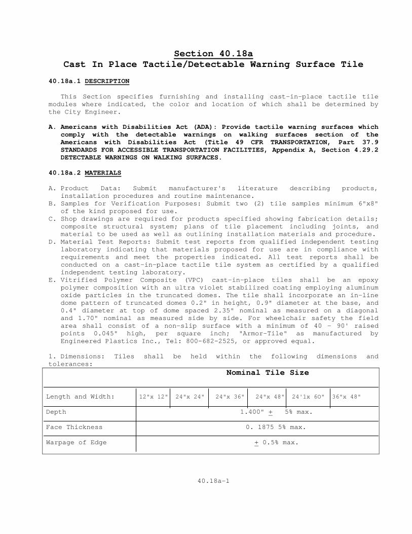
Section 40.18a Cast In Place Tactile/Detectable Warning Surface Tile
40.18a.1 DESCRIPTION This Section specifies furnishing and installing cast-in-place tactile tile modules where indicated, the color and location of which shall be determined by the City Engineer. A. Americans with Disabilities Act (ADA): Provide tactile warning surfaces which
comply with the detectable warnings on walking surfaces section of the Americans with Disabilities Act (Title 49 CFR TRANSPORTATION, Part 37.9 STANDARDS FOR ACCESSIBLE TRANSPORTATION FACILITIES, Appendix A, Section 4.29.2 DETECTABLE WARNINGS ON WALKING SURFACES.
40.18a.2 MATERIALS A. Product Data: Submit manufacturer's literature describing products,
installation procedures and routine maintenance. B. Samples for Verification Purposes: Submit two (2) tile samples minimum 6"x8"
of the kind proposed for use. C. Shop drawings are required for products specified showing fabrication details;
composite structural system; plans of tile placement including joints, and material to be used as well as outlining installation materials and procedure.
D. Material Test Reports: Submit test reports from qualified independent testing laboratory indicating that materials proposed for use are in compliance with requirements and meet the properties indicated. All test reports shall be conducted on a cast-in-place tactile tile system as certified by a qualified independent testing laboratory.
E. Vitrified Polymer Composite (VPC) cast-in-place tiles shall be an epoxy polymer composition with an ultra violet stabilized coating employing aluminum oxide particles in the truncated domes. The tile shall incorporate an in-line dome pattern of truncated domes 0.2" in height, 0.9" diameter at the base, and 0.4" diameter at top of dome spaced 2.35" nominal as measured on a diagonal and 1.70" nominal as measured side by side. For wheelchair safety the field area shall consist of a non-slip surface with a minimum of 40 - 90' raised points 0.045" high, per square inch; "Armor-Tile" as manufactured by Engineered Plastics Inc., Tel: 800-682-2525, or approved equal.
1. Dimensions: Tiles shall be held within the following dimensions and tolerances:
Nominal Tile Size Length and Width: 12"x 12" 24"x 24" 24"x 36" 24"x 48" 24'1x 6O" 36"x 48" Depth 1.400" + 5% max. Face Thickness 0. 1875 5% max. Warpage of Edge + 0.5% max.
40.18a-1
2. Water Absorption of Tile when tested by ASTM-D 570 not to exceed 0.35%. 3. Slip Resistance of Tile when tested by ASTM-C 1028 the combined wet/dry static
co-efficient of friction not to be less than 0.90 on top of domes and field area.
4. Compressive Strength of tile when tested by ASTM-D 695-91 not to be less than 18,000 psi. Tensile Strength of Tile when tested by ASTM-D 638-91 not to be less than 10,000 psi.
5. Flexural Strength of Tile when tested by ASTM - C293-94 not to be less than 24,000 psi. Chemical Stain Resistance of Tile when tested by ASTM-D 543-87 to withstand without discoloration or staining - 1 % hydrochloric acid, urine, calcium chloride, stamp pad ink, gum and red aerosol paint.
6. Abrasive Wear of Tile when tested by BYK - Gardner Tester ASTM-D 2486* with reciprocating linear motion of 37± cycles per minute over a 10" travel. The abrasive medium, 40 grit Norton Metallite sandpaper, to be fixed and leveled to a holder. The combined mass of the sled, weight and wood block to be 3.2 lb. Average wear depth shall not exceed 0.030 after 1000 abrasion cycles measured on the top surface of the dome representing the average of three measurement locations per sample. Fire Resistance: When tested to ASTM E84 flame spread be less than 25.
7. Gardner Impact to geometry "GE" of the standard when tested by ASTM-D 5420-93 to have a mean failure energy expressed as a function of specimen thickness of not less than 450 in. lbf/in. A failure is noted if a hairline fracture is visible in the specimen.
8. Accelerated Weathering of Tile when tested by ASTM-G26-95 for 2000 hours shall exhibit the following result - no deterioration, fading or chalking of surface of tile.
F. Vitrified Polymer Composite (VPC) Cast-in-Place Tiles embedded in concrete
shall meet or exceed the following test criteria: 1. Accelerated Aging and Freeze Thaw Test of Tile when tested to ASTM-D 1037
shall show no evidence of cracking, delamination, warpage, checking, blistering, color change, loosening of tiles or other defects.
2. Salt and Spray Performance of Tile and Adhesive System when tested to ASTM-B 117 not to show any deterioration or other defects after 100 hours of exposure.
G. Embedment flange spacing shall be 3.0" minimum to 3.1 " maximum center to
center spacing as illustrated on product drawing. 40.18a.3 SITE CONDITIONS A. Environmental Conditions and Protection: Maintain minimum temperature of 40
deg. F in spaces to receive tactile tiles for at least 48 hours prior to installations, during installation, and for not less than 48 hours after installation. Store tactile tile material in spaces where they will be installed for at least 48 hours before beginning installation. Subsequently, maintain minimum temperature of 40OF in areas where work is completed.
40.18a-2
B. The use of water for work, cleaning or dust control, etc. shall be contained and controlled and shall not be allowed to come into contact with the passengers or public. Provide barricades or screens to protect passengers or public. Disposal of any liquids or other materials of possible contamination shall be made in accordance with federal state and local laws and ordinances.
C. Cleaning materials shall have code acceptable low VOC solvent content and
low flammability if used on the site. 40.18a.4 GUARANTEE A. Cast-in-place tactile tiles shall be guaranteed in writing for a period of
five years from date of final completion. The guarantee includes defective work, breakage, deformation, and loosening of tiles.
B. Color: Yellow conforming to Federal Color No. 33538. Color shall be homogeneous throughout the tile. Tiles are also available in Light Grey, Dark Grey, Onyx Black, Pearl White, Brick Red.
40.18a.5.1 INSTALLATION A. During all concrete pouring and tile installation procedure, ensure
adequate safety guidelines are in place and that they are in accordance with the applicable industry and government standards.
B. The specifications of the concrete sealants and related materials shall be
in strict accordance with the contract documents and the guidelines set by their respective manufacturers.
C. The physical characteristics of the concrete shall be consistent with the
contract specifications while maintaining a slump range of 4 - 7 to permit solid placement of the Cast-In-Place Tile System. An overly wet mix will cause the Cast-In-Place System to float, therefore under these conditions suitable weights such as 2 concrete blocks or sandbags (25 lb) shall be placed on each tile.
D. Prior to placement of the Cast-In-Place System, the contract drawings
shall be reviewed. E. The concrete pouring and finishing operations require typical mason's
tools, however, a 4' long level with electronic slope readout, 25 lb. weights, vibrator and small sledge hammer with 2" x 6" x 20" wood tamping plate are specific to the installation of the Cast-In Place System.
F. The concrete shall be poured and finished, true and smooth to the required
dimensions and slope prior to tile placement. Immediately after finishing the concrete, the electronic level should be used to check that the required slope is achieved. The tile shall be placed true and square to the curb edge in accordance with the contract drawings. The Cast-In-Place Tiles shall be tamped or vibrated into the fresh concrete to ensure that the field level of tile is flush to the adjacent concrete surface. The contract drawings indicate that the tile field level (base of truncated dome) is flush to adjacent surfaces to permit proper water drainage and eliminate tripping hazards between adjacent finishes. The tolerance for elevation differences between tile and adjacent surface is 1/16".
40.18a-3
G. Immediately after tile placement, the tile elevation is to be checked to adjacent concrete. The tile elevation and slope should be set consistent with contract drawings to permit water drainage to curb as the design dictates.
H. While concrete is workable a steel trowel shall be used to trowel the
concrete around the tile perimeter to the field level of the tile. 1. During and after the tile installation and the concrete curing stage, it is
imperative that there is no walking, leaning or external forces placed on the tile to rock the tile, causing a void between the underside of tile and concrete.
Following tile placement, review installation tolerances to contract drawings and adjust tile before the concrete sets, 2 suitable weights of 25 lb. each shall be placed on each tile as necessary to ensure solid contact of tile underside of concrete. K. Following the curing of the concrete, the protective plastic wrap is to be
removed from the tile face by cutting the plastic with a sharp knife tight to the concrete/tile interface. If concrete bleeding occurs, a wire brush will clean the residue without damage to the tile surface.
40.18a.5.2 CLEANING AND PROTECTING A. Protect tiles against damage during construction period to comply with
tactile tile manufacturer's specification. B. Protect tiles against damage from rolling loads following installation by
covering with plywood or hardwood. Clean tactile tiles not more than four days prior to date scheduled for inspection intended to establish date of substantial completion in each area of project. Clean tactile tile by method specified by tactile tile manufacturer. 40.18a.6 METHOD OF MEASUREMENT This work will be measured for payment as cast-in-place tactile tile modules and will be measured by the Engineer for the actual number of tiles completed and accepted. 40.18.5 BASIS OF PAYMENT Concrete sidewalk will be paid for at the contract unit price, per tile, for "cast-in-place tactile tile" complete in place, which price shall include all material, equipment, tools and labor incidental thereto.
40.18-1a4

Section 40.18b Surface Applied Tactile/Detectable Warning Surface Tile
40.18a.1 DESCRIPTION This Section specifies furnishing and installing Surface Applied tactile tile modules where indicated, the color and location of which shall be determined by the City Engineer. A. Americans with Disabilities Act (ADA): Provide tactile warning surfaces which
comply with the detectable warnings on walking surfaces section of the Americans with Disabilities Act (Title 49 CFR TRANSPORTATION, Part 37.9 STANDARDS FOR ACCESSIBLE TRANSPORTATION FACILITIES, Appendix A, Section 4.29.2 DETECTABLE WARNINGS ON WALKING SURFACES.
40.18a.2 MATERIALS A. Product Data: Submit manufacturer's literature describing products,
installation procedures and routine maintenance. B. Samples for Verification Purposes: Submit two (2) tile samples minimum 6"x8"
of the kind proposed for use. C. Shop drawings are required for products specified showing fabrication details;
composite structural system; plans of tile placement including joints, and material to be used as well as outlining installation materials and procedure.
D. Material Test Reports: Submit test reports from qualified independent testing laboratory indicating that materials proposed for use are in compliance with requirements and meet the properties indicated. All test reports shall be conducted on a Surface Applied tactile tile system as certified by a qualified independent testing laboratory.
E. Vitrified Polymer Composite (VPC) Surface Applied tiles shall be an epoxy polymer composition with an ultra violet stabilized coating employing aluminum oxide particles in the truncated domes. The tile shall incorporate an in-line dome pattern of truncated domes 0.2" in height, 0.9" diameter at the base, and 0.4" diameter at top of dome spaced 2.35" nominal as measured on a diagonal and 1.70" nominal as measured side by side. For wheelchair safety the field area shall consist of a non-slip surface with a minimum of 40 - 90' raised points 0.045" high, per square inch; "Armor-Tile" as manufactured by Engineered Plastics Inc., Tel: 800-682-2525, or approved equal.
1. Dimensions: Tiles shall be held within the following dimensions and tolerances:
Nominal Tile Size Length and Width: 12"x 12" 24"x 24" 24"x 36" 24"x 48" 24'1x 6O" 36"x 48" Depth 1.875" + 5% max. Face Thickness 0. 1875 5% max. Warpage of Edge + 0.5% max.
40.18b-1
2. Water Absorption of Tile when tested by ASTM-D 570 not to exceed 0.35%. 3. Slip Resistance of Tile when tested by ASTM-C 1028 the combined wet/dry static
co-efficient of friction not to be less than 0.90 on top of domes and field area.
4. Compressive Strength of tile when tested by ASTM-D 695-91 not to be less than 18,000 psi. Tensile Strength of Tile when tested by ASTM-D 638-91 not to be less than 10,000 psi.
5. Flexural Strength of Tile when tested by ASTM - C293-94 not to be less than 24,000 psi. Chemical Stain Resistance of Tile when tested by ASTM-D 543-87 to withstand without discoloration or staining - 1 % hydrochloric acid, urine, calcium chloride, stamp pad ink, gum and red aerosol paint.
6. Abrasive Wear of Tile when tested by BYK - Gardner Tester ASTM-D 2486* with reciprocating linear motion of 37± cycles per minute over a 10" travel. The abrasive medium, 40 grit Norton Metallite sandpaper, to be fixed and leveled to a holder. The combined mass of the sled, weight and wood block to be 3.2 lb. Average wear depth shall not exceed 0.030 after 1000 abrasion cycles measured on the top surface of the dome representing the average of three measurement locations per sample. Fire Resistance: When tested to ASTM E84 flame spread be less than 25.
7. Gardner Impact to geometry "GE" of the standard when tested by ASTM-D 5420-93 to have a mean failure energy expressed as a function of specimen thickness of not less than 450 in. lbf/in. A failure is noted if a hairline fracture is visible in the specimen.
8. Accelerated Weathering of Tile when tested by ASTM-G26-95 for 2000 hours shall exhibit the following result - no deterioration, fading or chalking of surface of tile.
F. Vitrified Polymer Composite (VPC) Surface Applied tiles embedded in concrete
shall meet or exceed the following test criteria: 1. Accelerated Aging and Freeze Thaw Test of Tile when tested to ASTM-D 1037
shall show no evidence of cracking, delamination, warpage, checking, blistering, color change, loosening of tiles or other defects.
2. Salt and Spray Performance of Tile and Adhesive System when tested to ASTM-B 117 not to show any deterioration or other defects after 100 hours of exposure.
G. Embedment flange spacing shall be 3.0" minimum to 3.1 " maximum center to
center spacing as illustrated on product drawing. 40.18a.3 SITE CONDITIONS A. Environmental Conditions and Protection: Maintain minimum temperature of 40
deg. F in spaces to receive tactile tiles for at least 48 hours prior to installations, during installation, and for not less than 48 hours after installation. Store tactile tile material in spaces where they will be installed for at least 48 hours before beginning installation. Subsequently, maintain minimum temperature of 40OF in areas where work is completed.
B. The use of water for work, cleaning or dust control, etc. shall be contained
and controlled and shall not be allowed to come into contact with the passengers or public. Provide barricades or screens to protect passengers or public. Disposal of any liquids or other materials of possible contamination shall be made in accordance with federal state and local laws and ordinances.
40.18b-2
C. Cleaning materials shall have code acceptable low VOC solvent content and low flammability if used on the site.
40.18a.4 GUARANTEE A. Surface Applied tactile tiles shall be guaranteed in writing for a period of
five years from date of final completion. The guarantee includes defective work, breakage, deformation, and loosening of tiles.
B. Color: Yellow conforming to Federal Color No. 33538. Color shall be homogeneous throughout the tile. Tiles are also available in Light Grey, Dark Grey, Onyx Black, Pearl White, Brick Red.
40.18a.5.1 INSTALLATION
A. During all surface preparation and tile installation procedures ensure adequate safety guidelines are in place and that they are in accordance with the applicable industry and government standards
B. The application of all tile, adhesives, mechanical fasteners, and caulking
shall be in strict accordance with the guidelines set by their respective manufactures.
C. Work with the Contractor or Engineer to ensure that the surfaces being
prepared and fabricated to receive the tiles, are constructed correctly and adequately for tile installation. Review design drawings with the Contractor prior to the construction and refer any and all discrepancies to the Engineer.
D. The surface to receive the detectable warning surface tile is to be
mechanically cleaned with a diamond cup grinder or shop blaster to remove any dirt or foreign material.
E. Immediately prior to installing the detectable warning surface tile, the
concrete surfaces must be inspected to ensure that they are clean, dry, free of voids, curing compounds, projections, loose material, dust, oil, grease, sealers and determined to be structurally sound and cured for 30 days.
F. Apply the adhesive on the backside of the tile and following the perimeter
and internal cross pattern established by the tile manufacturer. Sufficient adhesive must be placed on the prescribed areas to have full coverage across the 2" width of the adhesive locator.
G. Set the tile true and square to the curb ramp area as detailed in the
design drawings. H. Drill holes true and straight to a depth of 31/2" using the recommended
diameter bit. The twelve countersunk holes are located in the molded recess provided in the tile.
I. Fastener has been set to fall depth, straight and true flush to the top of
dome. Care should be taken when setting the fastener to avoid any inadvertent blows to the tile surface.
40.18b-3
J. Following the installation of the tiles, the perimeter caulking sealant should be applied to the perimeter edge. Follow the perimeter caulking sealant manufacturer's recommendations when applying the caulking. Tape all perimeter edges of the tile edge leaving 3/16" of the tile exposed and also tape the adjacent concrete back 1/2" from the tiles perimeter edge. Tool the perimeter sealant caulking with a plastic applicator to create a straight edge in a cove profile between the tile and adjacent concrete. Remove tape immediately after tooling perimeter caulking sealant.
K. Do not allow foot traffic on installed tiles until the perimeter sealant
caulking has cured sufficiently to avoid tracking. 40.18a.5.2 CLEANING AND PROTECTING A. Protect tiles against damage during construction period to comply with tactile
tile manufacturer's specification. B. Protect tiles against damage from rolling loads following installation by
covering with plywood or hardwood. Clean tactile tiles not more than four days prior to date scheduled for inspection intended to establish date of substantial completion in each area of project. Clean tactile tile by method specified by tactile tile manufacturer. 40.18a.6 METHOD OF MEASUREMENT This work will be measured for payment as Surface Applied tactile tile modules and will be measured by the Engineer for the actual number of tiles completed and accepted. 40.18.5 BASIS OF PAYMENT Concrete sidewalk will be paid for at the contract unit price, per tile, for "Surface Applied tactile tile" complete in place, which price shall include all material, equipment, tools and labor incidental thereto.
40.18b-4
SECTION 40.19 RESET STONE CURB
40.19.1 DESCRIPTION Work under this item shall consist of the removal, relocation, transporting and resetting of Stone Curb at the locations and to the dimensions shown on the Contract Plans and in accordance with these specifications. The relocated stone curb may be used for stepping stones, around planters, curbs or in such other manner as shown on the Contract Plans. 40.19.2 MATERIAL 1. Stone curb shall be salvaged from existing locations shown on the Contract
Plans or procured from City stock piles by the Contractor. 2. Gravel for bedding shall conform to Section 2.02.02 of these Specifications. 40.19.3 CONSTRUCTION METHODS Where shown on the Contract Plans or as directed by the Engineer, all existing stone curb to be relocated shall be removed with extreme caution and safely stockpiled for reuse. Sections rejected by the Engineer because of conditions not the fault of the Contractor shall be disposed of by the Contractor. The salvaged stone shall be relocated and set as shown on the Contract Plans. Any extra stone curb not needed for the work shall be delivered and neatly piled at Central Service Building, 99 Middletown Avenue, New Haven, Connecticut or where directed by the Engineer within the City limits. If due to the Contractor's operations any of the stone is damaged, the Contractor shall replace the damaged stone curb with like curb. The setting of the stone curb shall conform with Section 40.09.3 of these Contract Specifications. Where used for steps, stepping stones or planter edging, the stone shall be installed in conformance with the plans. 40.19.4 METHOD OF MEASUREMENT
This work will be measured for payment by the actual number of linear feet of "Reset Stone Curb" installed and accepted. Measurement to be made along the top face of curb or step. In the case of stepping stones measurement shall be along the longer edge of each stone set. 40.19.5 BASIS OF PAYMENT Payment for this work will be made at the contract unit price for "Reset Stone Curb" complete and in place, which price shall include all materials, equipment, tools, gravel base, and labor necessary to complete the work. Said price shall include excavation of all materials, necessary removal of all pavements and bases, the removal of existing curb to be relocated, the installation of the stone curbs at the location shown on the Contract Plans the loading, transportation, unloading and piling of surplus stone curb as specified or directed the replacement of any pavement removed and all incidental work necessary for the complete installation of the relocated and reset stone as specified. When no item for "Reset Stone Curb" appears in the proposal, the cost of this work shall be included in the various contract unit prices.

40.19-1
SECTION 41.01 WOODEN CURBING
41.01.1 DESCRIPTION This item shall consist of constructing wooden curbing in the locations and to the dimensions and details as shown on contract plans or as directed by the engineer all in accordance with these specifications. 41.01.2 MATERIALS Wood shall be six inches by six inches in cross section and in at least six foot lengths and be either new or used and in a condition acceptable to the engineer. It shall be free of major splits, fractures, and splinters, and shall have smooth surfaces but not a finished surface. It shall be treated with a wood weather-proofing treatment, however, creosoting is not acceptable. Spikes shall be at least 1/2" in diameter and four feet long. They shall be steel and have hexagonal heads on one end. 41.01.3 CONSTRUCTION METHODS The wooden curbs shall be placed on a prepared (leveled and compacted) surface either of bituminous, gravel, stone or earth. They shall be placed to the dimension and alignment shown on the contract plans. Adjacent lengths of curb shall have not more than a 1/4" space between them. The ends of the two lengths of curb which form a corner other than a right angle shall be cut on the bias. Holes shall be drilled through the curb to snugly receive the steel spikes. They shall be spaced a maximum of five foot centers of a maximum of 18" from each end of a curb length, whichever is less. The spikes shall be driven into the ground so that only the heads of the spike protrude above the surface. The backside of the curb shall be backfilled with earth, sloped to meet the existing ground and tamped. 41.01.4 METHOD OF MEASUREMENT This work will be measured for payment as the actual number of linear feet of wooden curbing completed and accepted by the Engineer. 41.01.5 BASIS OF PAYMENT Payment for this work will be made at the contract unit price per linear foot for "Wooden Curbing" complete in place, which price shall include all materials, equipment, tools, and labor incidental thereto; all leveling, compacting and backfilling.

40.01-1
SECTION 41.02 PAVEMENT SEALER
41.02.01 DESCRIPTION This item shall consist of spreading an approved pavement sealer over all bituminous concrete surfaces at the locations shown on the contract drawings or as ordered by the Engineer. 41.02.02 MATERIALS Pavement sealer shall be Jennite J-16 as manufactured by Maintenance, Inc., Wooster, Ohio or approved equal. 41.02.3 CONSTRUCTION METHODS Bituminous concrete pavement shall be prepared and sealed with two coats of Jennite J-16 in accordance with Maintenance, Inc., General Application Specifications Index JA. Coverage: 0.15 to 0.20 gallons of Jennite J-16 per square yard or equivalent coverage by method recommended by the manufacturer of the approved equal pavement sealer. 41.02.04 METHOD OF MEASUREMENT This item of work shall be measured for payment by the actual number of square yards of bituminous concrete pavement sealed and approved by the Engineer. 41.02.05 BASIS OF PAYMENT This item will be paid for at the contract unit price per square yard for "Pavement Sealer," complete in place, which price shall include the cost of furnishing and application of the pavement sealer and all equipment, tools, labor and materials incidental thereto.

41.02-1
SECTION 41.03 TIMBER RAIL FENCE AND TIMBER BOLLARD
41.03.1 DESCRIPTION, MATERIALS, AND CONSTRUCTION METHODS Under this item, the contractor shall furnish and install pressure treated wood posts and rails as indicated on the plans and herein specified. Wood for the timber rail assembly or timber bollard shall be Southern Yellow Pine, Grade #1 SR (Stress Rated) as described in "Grading Rules of the Southern Pine Inspection Bureau," (latest edition) and of the dimensions shown on the contract drawings. The wood shall be impregnated with pentachlorophenol for a minimum retention of twelve (12) pounds per cubic foot. Pressure impregnation shall be in full compliance with the applicable standards of the American Wood Preservers Association. The Contractor shall furnish to the Engineer a notarized "Certificate of Treatment" attesting to the fact that the posts and rails have been properly treated in conformance with these specifications. All posts shall be free from injurious checks, cracks, red heart and decay. The diameter of any knot shall not exceed 3 inches. Posts shall be straight so that a line from the center of the butt to the center of the tip will not deviate more than 1 inch from the center of the post. Fasteners shall be as detailed and recommended for the particular application, and shall meet the requirements of ASTM A153. The posts shall be installed to the full depths indicated on the contract drawings and shall be plumb so as to receive the rails. 41.03.2 METHOD OF MEASUREMENT The quantity of timber rail fence measured for payment shall be the number of lineal feet of rail installed and accepted. The quantity of timber bollards measured for payment shall be the number of each installed and accepted. 41.03.3 BASIS OF PAYMENT The timber rail fence or timber bollard will be paid for at the contract price per lineal foot of "Timber Rail Fence" or "Timber Bollard" complete in place, which price shall include all posts and other materials, related earthwork for post setting, tools and labor necessary for a complete installation.

41.03-1
SECTION 41.04 STRIPE PAINTING
41.04.1 DESCRIPTION This work shall consist of the furnishing and application of paint on the bituminous concrete surface as shown on the Contract Drawings or as ordered by the Engineer. 41.04.2 MATERIALS All materials shall conform to the following requirements and shall be accepted by the Engineer prior to use in the work involved. Stripe paint shall conform to the requirements of the New Haven Traffic and Parking Department. Yellow painting shall be Code C-964 as manufactured by the Franklin Paint Co., 259 Cottage Street, Franklin, Massachusetts, or approved equal. White paint shall be Code 9221 as manufactured by the Prismo Safety Corporation, Huntington, Pennsylvania, or approved equal. 41.04.3 CONSTRUCTION METHODS Work shall conform to the following requirements, unless otherwise directed by the Engineer. Stripe painting shall not be applied when the air temperature is below 40 o F, or when the air is misty, or when in the opinion of the Engineer conditions are not satisfactory for the work. Painting shall be done in a neat workmanlike manner, applied with hand brushes or other acceptable methods to make a continuous stripe of constant width at the locations shown on the plans. Paint shall be applied smoothly and uniformly to an even coat, so that no excess paint will collect at any point. Paint shall be applied as recommended by the manufacturer and as directed by the Engineer. 41.04.4 METHOD OF MEASUREMENT The number of lineal feet of stripe painting to be measured for payment shall be the actual number of feet of single width stripes painted. 41.04.5 BASIS OF PAYMENT Payment for this work shall be at the contract unit price per lineal foot stripe painting and shall include the cost of all equipment, labor and materials necessary for stripe painting.

41.04-1
SECTION 41.04 THERMOPLASTIC REFLECTORIZED PAVEMENT MARKINGS
41.04.1 DESCRIPTION:
Under this work the Contractor shall furnish and apply thermoplastic reflectorized pavement markings at the location and in accordance with the patterns indicated on the plans, or as directed by the Engineer, and in accordance with these specifications.
The thermoplastic pavement marking compound shall be extruded in a molten state on a primed surface. Following surface application of glass beads and upon cooling to normal surface temperature, the resultant marking shall be an adherent reflectorized stripe of the specified thickness and width that is capable of resisting deformation by traffic.
41.04.2 MATERIALS:
Materials shall conform to requirements of AASHTO Designation: M249-79 White and Yellow Thermoplastic Striping Material (Solid Form).
41.04.3 CONSTRUCTION METHODS:
41.04.31 Equipment General
Thermoplastic applicating equipment shall be approved by the Engineer prior to the start of work.
Thermoplastic material shall be applied to the primed pavement surface by the extrusion method, wherein one side of the shaping die is the pavement and the other three sides are contained by, or are part of, suitable equipment for maintaining the temperature and controlling the flow of material.
For heating the thermoplastic composition, the application equipment shall include a melting kettle(s) of such capacity as to allow for continuous marking operations. The melting kettle(s) may be mounted on a separate "supply" vehicle or included as part of the mobile applicating equipment. The composition temperatures greater than 400 Degs. F. Heating mechanism shall be by means of a thermostatically controlled heat transfer medium. Heating of the composition by direct flame will not be allowed. Material temperature gauges shall be visible at both ends of the kettle(s).
Application equipment shall be constructed to provide continuous mixing and agitation of the material. Conveying parts of the equipment between the main material reservoir and the extrusion shoe(s) shall be so construed as to prevent accumulation and clogging. All parts of the equipment which come into contact with the material shall be so constructed as to be easily accessible and exposable for cleaning and maintenance. The equipment shall be so that all mixing and conveying parts up to and including the extrusion shoe(s) maintain the material at the required plastic temperature.
The applicating equipment shall be so constructed as to insure continuous uniformity in the dimensions of the stripe. The applicator shall provide a method of applying "skip lines". The equipment shall be capable of applying varying width of traffic markings.
The applicator shall be equipped with drop-on type bead dispenser capable of uniformly dispensing reflective glass spheres at controlled rates of flow.
The bead dispenser shall be automatically operated in such a manner that it will only dispense beads while the composition is being applied.
41.04-1 Applicating equipment shall be mobile and maneuverable to the extent that straight lines can be followed and normal curves can be made in a true arc.
Applicators shall be equipped and constructed in such a manner as to satisfy the requirements of the National Board of Fire Underwriters and the appropriate agencies of the State of Connecticut.
The equipment used for theplacement of thermoplastic pavement markings shall be two general types: mobile applicator and portable applicator.
41.04.32 Mobile Applicating Equipment
The mobile applicator shall be defined as a truck mounted, self contained pavement marking machine that is capable of hot applying thermoplastic by extrusion method. The unit shall be equipped to apply the thermoplastic material at temperatures exceeding 400 degrees F., and at the widths and thickness specified herein. The mobile unit shall be capable of operating continuously and of installing a minimum of 20,000 linear feet of longitudinal markings in an 8-hour day.
The mobile unit shall be equipped with a melting kettle(s) or materials storage reservoir(s) of such capacity as to allow for continuous marking operations. The kettle(s) or reservoir(s) shall be capable of heating or holding the thermoplastic composition at temperatures greater than 400 degrees F.
The mobile unit shall be equipped with an extrusion shoe(s), and shall be capable of marking edgeline and centerline stripes. The extrusion shoe(s) shall be closed, heat jacketed or suitably insulated unit; shall hold the molten thermoplastic at a temperature greater than 400 degrees F.; and shall be capable of extruding a line of from 3 to 8 inches in width; and at a thickness of not less than 1/8" nor more than 3/16", and of generally uniform cross section. Material temperature gauges shall be affixed or incorporated in the extrusion shoe in such a manner as to be visible, and capable of monitoring the composition temperature throughout the marking operation.
The mobile unit shall be equipped with an electronic and programmable line pattern control system, or mechanical control system, so as to be capable of applying skip or solid lines in any sequence, and through any extrusion shoe in any cycle length.
41.04.33 Portable Applicating Equipment
The portable applicator shall be defined as hand operated equipment, specifically designed for placing thermoplastic installations such as crosswalks, stop bars, legends, arrows, and short lengths of lane, edge and centerlines. The portable applicator shall be capable of applying thermoplastic pavement markings by the extrusion method. It is intended that the portable applicator will be loaded with hot thermoplastic composition from the melting kettle(s). The portable applicator shall be equipped with all the necessary components, including a materials storage reservoir, bead dispenser, extrusion shoe, and heating accessories, so as to be capable of holding the molten thermoplastic at temperatures greater than 400 degrees F., of extruding a line of from 3 to 8 inches in width, and in thickness of not less than 1/8" nor more than 3/16", and of generally uniform cross-section. Material temperature gauges shall be affixed or incorporated in the extrusion shoe in such a manner as to be visible, and capable of monitoring the composition temperature throughout the marking operation.
41.04.34 Application General
All equipment markings and patterns shall be placed as shown on the plans and in accordance with the Manual of Uniform Traffic Control Devices.
Before any pavement marking work is begun, a schedule of operations shall be submitted for the approval of the City Traffic Engineer or his authorized representative.
41.04-2 When pavement markings are applied under traffic the Contractor shall provide all necessary flags, markers, signs, etc. to maintain and protect traffic; and to protect marking operations and the marking until thoroughly set.
The application of pavement markings shall be done in the general direction of traffic. Striping against the direction of traffic flow shall not be allowed.
The Contractor shall be responsible for removing, to the satisfaction of the Engineer, tracking marks, spilled thermoplastic or thermoplastic applied in unauthorized areas.
When necessary, the Contractor shall establish marking line points at twenty-five (25) foot intervals throughout the length of pavement or as directed by the Engineer.
41.04.35 Atmospheric Conditions
Thermoplastic pavement markings shall be placed upon dry pavement surfaces. At the time of installation the pavement surface temperature shall be a minimum of 55 degrees F. and the ambient temperature shall be a minimum of 49 degrees F. and rising. The Engineer will determine when atmospheric conditions are such to produce satisfactory results (Note 2).
Note 2. To comply with the 55 degree F Temperature requirement, it will benefit the Contractor to schedule striping work for seasons of warm weather when possible. In cooler conditions, striping operations may coordinate with bituminous paving work to take advantage of residual heat, providing that the ambient temperature requirements of subsection 41.04.35 are still met.
41.04.36 Materials Application Requirements
A. Primer. All pavement surfaces (new or existing) shall be primed. Type I, II, and III primes as specified in AASHTO Designation: M249-79 shall be applied at the following rates:
1. Type I Primer - shall be applied to bituminous concrete Pavement only, at a wet film thickness of 5 + 1 mil (265-400 s.f. /gal).
2. Type II Primer - shall be applied to either bituminous concrete or Portland cement concrete pavements (including concrete bridge decks) at a wet film thickness of between 4 to 5 mils (320-400 s.f. s.f. gal.).
3. Type III Primer - shall be applied to bituminous concrete pavement at the rates and in accordance with recommendations of the manufacturer of the thermoplastic composition.
B. Thermoplastic Composition.
1. Application Temperature - thermoplastic composition shall be applied at temperatures no lower than 400 degrees F. at the point of deposition. For purposes of these specifications, the point of deposition shall be defined as within the extrusion shoe.
2. Extruded Markings - all extruded markings shall be applied at the specified width, and at a thickness of not less than 1/8" nor more than 3/16". C. Reflective Glass Spheres (for Drop-on). Immediately following application, reflective glass spheres are specified in AASHTO Designation: M247-81 glass beads used in traffic paint shall be dropped onto molten thermoplastic marking at the rate of one (1) pound per 20 square feet of composition.
41.04-3 41.04.37 Surfaces Cleaning and Preparation of Pavement
The Contractor shall be responsible for cleaning the pavement surface to the satisfaction of the Engineer.
Surface cleaning and preparation work shall be performed only in the area of the thermoplastic markings application.
At the time of application all pavement surfaces shall be free of oil, dirt, dust, grease and similar foreign materials. The cost of cleaning these contaminants shall be included in the bid price of this item.
In addition, concrete curing compounds on new Portland Cement concrete surfaces; and existing pavement markings on both concrete and bituminous pavement surfaces shall be cleaned and paid for under separate items.
41.04.38 Application of Thermoplastic Pavement Markings
All special markings, cross-walks, stop bars, legends, arrows and similar patterns shall be placed with a portable applicator. Unless otherwise specified in the contract documents all centerline, skip line, edge line and other longitudinal type markings may be applied with either a portable or mobile applicator.
When the surface preparation work has been completed, if applicable, the bituminous and/or concrete pavement surface shall be primed. The primer shall be applied with spray equipment. Unless otherwise recommended by the manufacturer, primer materials shall be allowed to "set-up” prior to applying the thermoplastic composition, Type I primer shall be allowed to dry to a tack-free condition; usually occurring in less than 10 minutes. Type II primer shall be allowed to dry to a "tacky” condition, which usually occurs within 15 minutes under normal conditions. Type III primer that have been recommended by the manufacturer shall be allowed to dry for the directed time period. To shorten the curing time of epoxy resin type primers, an infra-red heating device may be used.
Pavement surfaces that are primed and not striped with thermoplastic within the specified set time or within the same work day, as applicable, shall be re-primed.
After the primer has "set-up" the thermoplastic shall be applied at composition temperatures no lower than 400 degrees F. at the point of deposition. Immediately after installation of the marking, drop-on spheres shall be mechanically applied such that the spheres are held by and imbedded in the surface of the molten composition.
41.04.4 METHOD OF MEASUREMENT:
Pavement striping will be measured by linear feet along the centerline of the pavement stripe, and will be based on a 4 inch wide stripe. Measurement for striping with a plan width greater or less than the basic 4 inches as shown on the plans or as directed by the Engineer, will be made by the following method:
Plan Width of Striping (inches) x Linear Feet 4 (inches)
No payment will be made for the number of linear feet of skips in the dashed line.
Legends, arrows and markings will be measured for payment by the number of square feet of thermoplastic installed on the pavement accepted.
41.04.5 BASIS OF PAYMENT
This work shall be paid for at the contract unit price per square foot for "Legends, Arrows and Markings" and per linear foot of thermoplastic for "Pavement Striping of the width and color specified, installed on the pavement and accepted. This price shall include all premarking layout, cleaning off pavement, thermoplastic, glass beads, application of thermoplastic and glass beads, protection during drying,

maintaining and protection of traffic and all materials, equipment, tools, and labor incidental thereto.
41.04-4
SECTION 41.05 BITUMINOUS CONCRETE LIP CURBING
41.05.1 DESCRIPTION Bituminous concrete lip curbing shall consist of machine laid bituminous concrete, constructed on the pavement to the dimensions and details shown on the plans, or as ordered, and in conformity with the specifications. 41.05.2 MATERIALS Materials for this work shall conform to the requirements of Article M.04, Class 3 of the State Specifications. 41.05.3 CONSTRUCTION METHODS The provisions of Section 4.06 of the State Specifications govern, except that the requirements pertaining to samples and density will not apply. In addition, the curbing shall be constructed in accordance with the following requirements: Prior to the arrival of the mixture on the work, the surface of the pavement where the curbing is to be constructed shall be cleaned of all loose and foreign material. The surface, which shall be perfectly dry and clean at the time the mix is place, shall be coated with an approved tack coat just prior to placing the mixture. On arrival at the site, the mixture shall be transferred from the truck to the hopper of the curbing machine; and the mixture shall be kept clean and free from direct or foreign materials at all times. The surface of the curbing shall be tested with a 10-foot straight edge, and any variation from a true line exceeding 1/4 inch shall be satisfactorily corrected. The only compaction required shall be that obtained by the approved mechanical curbing machine. Where machine work is impractical, the Engineer may permit hand laid curbing to be constructed. If the design of the curbing machine is such that the outside wheels operate outside of the curb, the Contractor will be required to obtain a smooth surface by grading and consolidating the area on which the outside wheel of the machine rides, and this work shall be done at his expense. After the completion of curbing, vehicles shall be kept at a safe distance for a period of not less than 24 hours and until the curbing has set sufficiently to prevent injury to the work. 41.05.4 METHOD OF MEASUREMENT This work will be measured for payment along the top of the curb and will be the actual number of linear feet of bituminous concrete lip curbing completed and accepted. 41.05.5 BASIS OF PAYMENT This work will be paid for at the contract unit price per linear foot for "Bituminous Concrete Lip Curbing" complete in place, which price shall include all materials, equipment, tools and labor incidental thereto.
41.05-1
SECTION 41.06 PAVED DITCHES
41.06.1 DESCRIPTION Where called for on the plans or as directed by the Engineer, the Contractor shall construct paved ditches or paved leak-off ditches in conformity with the line, grade, compacted thickness and typical cross section shown on the plans. The surface course shall be Bituminous Concrete and the base course shall be Rolled Gravel. 41.06.2 MATERIALS Materials for this work shall conform to the following requirements: 1. Rolled Gravel Base shall conform to Section 2.02.2 of these contract
documents. 2. Bituminous Concrete shall conform to Section 2.03 of these contract
documents. 41.06.3 CONSTRUCTION METHODS The surface course and base course shall be constructed in conformity with Sections 40.10.2 and 40.13.3 of these Contract Documents. Sections inaccessible to the roller of distributor shall be hand tamped until thoroughly compacted and bituminous material shall be applied by means of hand equipment of a type approved by the Engineer. 41.06.4 METHOD OF MEASUREMENT The quantity to be included for payment under this item shall be the number of square yards of "Paved Ditch" actually constructed and accepted. The area shall be determined by using as a width the horizontal distance from outside to outside of the paved ditch or leak-off ditch and as a length the actual measured length along the surface. 41.06.5 BASIS OF PAYMENT This work will be paid for at the contract unit price per square yard for "Paved Ditch" complete in place, which price shall include all materials, tools, equipment and work incidental thereto, except excavation. Necessary excavation will be paid for at the contract unit price per cubic yard for "Ditch Excavation".

41.06-1
SECTION 41.07 BLUESTONE PAVING
41.07.1 DESCRIPTION This item of work shall consist of setting Bluestone paving stones at the locations shown on the Contract Plans or as ordered by the Engineer. 41.07.2 MATERIALS Stone for this work shall be of a good grade, free from structural defects and shall be approved by the Engineer. All stone used shall have a minimum surface dimensions of 2 feet by 1 foot and maximum surface dimensions of 3 feet by 3 feet. All stone shall have a minimum thickness of 3 inches. The stones shall have a "fine pointed" top surface, projections not to exceed 1/2 inch, and all edges shall be pitched to true lines. 41.07.3 CONSTRUCTION METHODS The Bluestone paving stones, graded so that the smaller stone is uniformly undistributed throughout the area shall be set in place over the area designated until the specified dimensions are attained. The stone shall be set flush with the surrounding area. 41.07.4 METHOD OF MEASUREMENT This item will be measured for payment by the actual number of square feet of Bluestone paving set in place and accepted by the Engineer. 41.07.5 BASIS OF PAYMENT This work will be paid for at the contract unit price per square foot of "Bluestone Paving" complete in place, which price shall include the cost of all materials, tools, equipment and labor incidental thereto.

41.07-1
SECTION 41.09 BRICK PAVING
41.09.1 DESCRIPTION This item of work shall consist of installing brick pavement on a prepared base course in the locations and to the dimensions and details shown on the Contract Plans or as ordered by the Engineer. 41.09.2 MATERIALS Brick shall be in conformance with the requirements of A.S.T.M. Specifications C-62 and shall be approved by the Engineer. 41.09.3 CONSTRUCTION METHODS Brick Pavement shall be carefully laid on a prepared base to the pattern and requirements shown on the Contract Plans. Bricks shall be firmly set in place and joints between bricks shall not exceed 1/4 inch. Joints shall be filled with sand for the full depth of the joint. The surface of the brick area shall be even as determined by laying a straight edge over the length and width of the area. 41.09.4 METHOD OF MEASUREMENT Brick paving will be measured for payment for the area in square feet complete and in place, by the Engineer. 41.09.5 BASIS OF PAYMENT Brick paving will be paid for at the contract unit price per square foot for "Brick Paving" complete in place, which price shall include the cost of all necessary excavation, backfilling, subgrade preparation, base course, brick and all other materials, labor and equipment incidental thereto.

41.09-1
SECTION 41.10 BITUMINOUS CONCRETE LIP CURBING
41.10.1 DESCRIPTION This lip curbing shall consist of machine laid bituminous concrete, constructed on the pavement to the dimensions and details shown on the plans, or as ordered by the Engineer, and in conformity with these specifications. 41.10.2 MATERIALS Materials for this work shall conform to the requirements of Section 2.03 for surface course, of these Contract Documents. 41.10.3 CONSTRUCTION METHODS The provisions of Section 40.13 of these Contract Documents shall govern, except that the requirements pertaining to samples and density will not apply. In addition, the curbing shall be constructed in accordance with the following requirements: Prior to the arrival of the mixture on the work, the surface of the pavement where the curbing is to be constructed shall be cleaned of all loose and foreign material. The surface which shall be perfectly dry and clean at the time the mix is placed shall be coated with an RC-2 or other approved bitumen just prior to placing the mixture. On arrival at the site, the mixture shall be transferred from the truck to the hopper of the curbing machine and the mixture shall be kept clean and free from direct or foreign materials at all times. The surface of the curbing shall be tested with a ten foot straight edge and any variation for a true line exceeding 1/4 of an inch shall be satisfactorily corrected. The only compaction required shall be that obtained by the approved mechanical curbing machine. Where machine work is impractical, the Engineer may permit hand laid curbing to be constructed. If the design of the curbing machine is such that the outside wheels operate outside of the curb, the Contractor will be required to obtain a smooth surface by grading and consolidating the area on which the outside wheel of the machine rides, and this work shall be done at his expense. After completion of curbing, traffic will be kept at a safe distance for a period of not less than 24 hours and until the curbing has set sufficiently to prevent injury to the work. 41.10.4 METHOD OF MEASUREMENT This item will be measured for payment by the actual number of linear feet of curb completed and accepted by the Engineer. Measurement will be made along the top of the curb. 41.10.5 BASIS OF PAYMENT This item will be paid for at the contract unit price per linear foot for "Bituminous Concrete Lip Curbing", complete in place, which price shall include the cost of all materials, labor and equipment incidental thereto.
41.10-1
SECTION 41.11 GRAVEL SERVICE ROAD
41.11.1 DESCRIPTION This surface shall consist of a one course wearing surface, composed of gravel, constructed on the prepared subgrade in accordance with these specifications and in conformity with the lines, grade, thickness and typical cross section as shown on the Plans. 41.11.2 MATERIALS The materials for this work shall consist of sound, tough, durable particles of gravel mixed with approved binding material and shall be free from thin or elongated pieces, lumps of clay, soil, loam or vegetable matter. The material may be bank-run or the binder may be added and incorporated by approved methods as herein specified, and shall conform to Section 2.02.2 of these Specifications. 41.11.3 CONSTRUCTION METHODS Before placing the material the Contractor shall shape the subgrade so that it is parallel and the specified depth below the finished surface as shown on the typical cross section. The material shall be spread on the subgrade to the depth shown on the Plans or as ordered by the Engineer. The spreading shall begin at the end of the project nearest the source of supply of the material in such a way that, as the work progresses, trucking is over material already in place so as to obtain as much compaction as possible during construction. No other rolling of the material will be required. The material shall be wetted, if directed, and shall be bladed, dragged and scraped to conform to the typical cross section as shown on the Plans. All areas of segregated coarse or fine material shall be corrected or removed and replaced with well graded material, as directed by the Engineer. If, after the material has been spread and shaped, it is found that additional binder is necessary, it shall be furnished and applied in the amount directed by the Engineer. Such binder material shall be carefully and evenly incorporated with the gravel in place by scarifying, harrowing, brooming or other approved methods. As the work progresses, the Contractor will be required, at the direction of the Engineer, to drag and reshape the material already in place and before completion and final acceptance he shall drag and reshape the entire project so as to leave the whole in a neat and presentable condition to the satisfaction of the Engineer. 41.11.4 METHOD OF MEASUREMENT This work will be measured for payment by the square yard of accepted material placed to the loose depth and width as shown on the Plans or as ordered by the Engineer. 41.11.5 BASIS OF PAYMENT This work will be paid for at the contract unit price per square yard for "Gravel Service Road", complete in place, which price shall include the formation of subgrade as described hereinbefore, all materials, tools, equipment and labor incidental thereto.

41.11-1
SECTION 40.12 BITUMINOUS CONCRETE BASE COURSE
40.12.1 DESCRIPTION
This item shall consist of the construction of a bituminous concrete bottom course or of a bituminous concrete leveling course composed of a coarse aggregate and sand, uniformly mixed with asphalt cement. It shall be constructed on the prepared surface in accordance with these Specifications and in conformity with the line, grade, compacted thickness and typical cross section as shown on the Plans.
40.12.2 MATERIALS
The materials for this work shall conform to Section 2.03 of these Specifications.
40.12.3 CONSTRUCTION METHODS
The methods employed in performing the work and all equipment, tools, machinery and other plant used in handling material and executing any part of the work, shall be subject to the approval of the Engineer before the work is started and, whenever found unsatisfactory, shall be changed and improved as required by the Engineer. All equipment, tools, machinery and plant used must be maintained in a satisfactory working condition.
1. Forms
When forms are required they shall be of a depth not less than the total proposed thickness of the bituminous concrete course or courses. The forms shall be of an approved section, straight, free from warps and bends a all times and shall be of sufficient strength when properly set and staked to resist the pressure of any bituminous mixture, and to remain true to line and grade throughout the entire rolling and compaction operation. The forms shall have properly designed joints and not less than three stake pockets to each ten-foot length.
The forms shall be accurately set to line and to such grade that after screeding by the finishing machine, the weight of mixture per square yard required for each course will be secured. The forms shall be tightly jointed and sufficiently braced so as to prevent the mixture squeezing out under the rolling. The width between the forms shall not vary more than one-half inch from the indicated width of the pavement.
The alignment and grade of all forms set shall be approved before and immediately prior to the placing of any material against them. Forms shall be cleaned thoroughly and oiled each time they are used. They shall remain in place until after the placing and final compaction of the surface course or courses. Care shall be exercised in rolling so as not to displace the line and grade of the forms.
2. Placing of Mixture
Immediately before placing the mixture the base surface shall be cleaned by brooming or by other means acceptable to the Engineer. Unless the restriction is waived by written consent of the Engineer, the mixture shall be laid only during the period from April 15 to October 15, and further, these operations shall be carried on only when the surface is dry, the atmospheric temperature in the shade is at least 50 degrees F. and the weather is not foggy or rainy. The Engineer may, however, permit work of this character to continue when overtaken by sudden storms, up to the amount which may be in transit from the plant at the time, provided the mixture is within temperature limits specified. Upon arrival, the mixture shall be dumped into the approved mechanical spreader and immediately spread and struck off to the full width required and to such appropriate loose depth for each successive course that when the work is completed the weight of the mixture required per square yard will be secured. Each course shall be struck off by the mechanical equipment. For use in striking off the bottom course the machine shall be equipped with easily adjustable strike-off plates. When approved in writing by the Engineer, the mechanical equipment may be omitted and spreading accomplished by hand.
In order to secure tight and well compacted longitudinal joints, the sequence of the bituminous concrete placing operations shall be subject to the control of the Engineer for all courses laid.
Before any rolling is started, the finished surface struck by the machine shall be checked, and inequalities adjusted, all "drippings" i.e., fat, sandy accumulations from the screed and all fat spots from any source, shall be removed and replaced by satisfactory material.
41.12-01
In areas where, on account of irregularities or unavoidable obstacles, the use of mechanical spreading and finishing equipment is impracticable, the mixture may be spread and screeded by hand.
When hand spreading is permitted by special provisions or when, because of any project conditions, it becomes necessary to spread by hand, the mixture, upon arrival, shall be dumped on approved steel dump sheets outside of the area on which it is to be spread and shall then be immediately distributed into place by means of suitable shovels and other tools and spread with metal lutes in a uniformly loose layer of such depth as will result in a completed pavement having the weight per square yard required. Any deviation from standard section shall be immediately remedied by placing additional material or removing surplus as directed. The Engineer may direct that other means of placing the material in addition to the metal lutes be used to insure a better control of the depths of material and the surface finish.
Contact surfaces of curbings, gutters, manholes, etc., shall be painted with a thin uniform coat of hot asphalt cement, or asphalt cement dissolved in naphtha, just before the material is placed against them. Where the bituminous material is spread on a concrete or an old bituminous base a uniform coat of asphalt shall be spread about one foot wide along each edge of the pavement to prevent water getting between the new pavement and the base. In any area where the new pavement is less than 1-1/2 inches thick and on steep grades the Engineer may order a very light web-like coating of hot asphalt paint applied to the old pavement. Care must be taken not to apply too heavy a coating or large blobs of asphalt paint.
The refueling of equipment in such position that fuel might be spilled on a bituminous concrete mixture already placed or to be placed, is prohibited.
Kerosene, gasoline or fuel oil for use in cleaning mechanical equipment or hand tools shall be stored well clear of areas paved or to be paved. Before any such equipment and tools are cleaned they shall be moved off the areas paved or to be paved, and they shall not be returned for use until after they have been allowed to dry.
3. Compaction
After the courses have been screeded as specified, each shall be rolled with power rollers as hereinafter provided. When the course spread has set sufficiently or come to the proper condition, it shall be rolled at such a speed as not to cause undue displacement or shoving.
Rollers to be used to compact the course shall be power driven rollers weighing not less than ten tons. If only one roller is used, it shall be a Tandem roller, a second roller may be of the three wheel type. The roller wheels shall be wet with only sufficient water to moisten the wheel surface.
Rolling shall begin at the sides and progress toward the center, uniformly lapping at least one-half the width of the compacting wheel of the roller. Alternate trips of the roller shall be terminated in stops at least three feet distant from any preceding stop. Other rolling procedure may be directed by the Engineer, as conditions may require. Rolling shall be discontinued if the surface shows signs of cracking and shall be continued later as directed.
The speed of the roller shall not exceed 3 miles per hour and shall at all times be slow enough to avoid displacement of the hot mixture. The rollers shall be in good condition. They shall be operated by experienced rollerman and must be kept in continuous operation as nearly as practicable in such manner that all parts of the pavement shall receive substantially equal compression.
In all places inaccessible to a roller, such as adjacent to curbs, headers, gutters, bridges, manholes, etc., the required compression shall be secured with tamps. Depressions which may develop before the completion of the rolling shall be remedied by adding new material to bring such depressions to a true surface. Should any depressions remain after the final compaction has been obtained, new material shall be added to form a true and even surface. All high spots, high joints and other defects shall be adjusted as directed by the Engineer.
4. Joints
Placing of the courses shall be as nearly continuous as possible and the roller shall pass over the unprotected end of the freshly laid mixture only when the laying of the course is discontinued or interrupted for an appreciable period, and joints shall be formed at such points. Where joints are to be formed the end of the freshly laid mixture shall be cut "square" with the pavement, slightly set up with the back of a metal lute and rolled at slow roller speed so as to cause as little feathering as possible. Before new material is laid the joint shall be cut back and a thin coating of hot asphalt applied to the joint. Care shall be taken to keep the asphalt paint off the surface of the pavement.
41.12-02
5. Surface Test of the Pavement
For the purpose of testing the finished surface, a standard template cut to the true cross section of the road shall at all time be available on the work, also a 10-foot straight edge.
The Contractor shall provide or designate some employee whose duty it is to use the straight edge and template in checking all rolled surfaces under the direction of the Engineer.
The finished pavement shall be such that it will not vary more than 1/4 inch from the template cut to the cross section of the road nor more than 1/4 inch from a 10-foot straight edge applied parallel to the center line of the pavement. Any irregularity of the surface exceeding the above limits shall be corrected. Depressions which may develop after the initial rolling shall be remedied by loosening the surface mixture laid, and adding new material to bring such depressions to a true surface. Such portions of the completed pavement as are defective in surface, compression or composition, or that do not comply with the requirements of the Specifications, shall be taken up, removed and replaced with suitable mixture properly laid in accordance with these Specifications at the expense of the Contractor.
6. Protection of the Work
Sections of the newly finished work shall be protected from traffic at least six hours, or until they have become properly hardened by cooling.
40.12.4 METHOD OF MEASUREMENT
This item will be measured for payment by the net weight in tons measured in the hauling vehicle. The Contractor is responsible for seeing that the City Inspector is given a weight slip showing the net weight of each load delivered on the job, and the same to be certified by the firm from which the Contractor purchased the product.
The total weight will be the summation of the weight slips of bituminous concrete actually incorporated in the work included under this item. The quantity to be included for payment for this work shall be subject to the following:
1. Determination of Thickness
Before final acceptance of the work or during the progress of the work, as the Engineer deems advisable, the thickness will be determined by measurements of cores taken at random points and the average of these core thicknesses will be considered as the average of four measurements along the sides of the core read to the nearest one-eighth inch.
2. Adjustment of Measured Weight
(a) No adjustment of the weight as determined from the weight slips will be made where the thickness does not exceed a tolerance of plus or minus one-half inch of the depth shown on the Plans.
(b) Where the thickness exceeds that shown on the plans by more than the allowable tolerance an amount equal to the computed weight of that material in excess of the Plan thickness plus one-half of an inch will be deducted from the weight determined from the weight slips.
(c) Where the thickness is less than that shown on the Plans by more than one-half of an inch and not more than three-quarters of an inch, there will be deducted an amount equal to 150 percent of the computed weight represented by that deficiency.
(d) Where the thickness is less than that shown on the Plans by more than three-quarters of an inch, the Contractor, with the permission of the Engineer, shall place a correction course not less than one inch in depth after compaction provided an acceptable grade and cross-section can be achieved. Where an acceptable grade and cross-section cannot be achieved through the above means, the Contractor shall reconstruct by cutting back and into the pavement having no more than three-quarters of an inch deficiency in thickness a sufficient distance to permit the placement of an acceptable depth and place new material to achieve the proper depth, cross section and profile. These areas where a corrective course is placed or reconstruction of the pavement is performed, will be re-cored and re-measured again as though originally constructed; no compensation will be made to the Contractor for materials removed, their removal or disposal or for restoration of affected supporting base or adjacent construction.
(e) An adjustment in quantity will be made in the bituminous concrete place beyond the horizontal limits indicated on the plans by deducting the computed weight of that material extending more than three inches beyond the horizontal Plan dimensions.
3. Computed Weight
The computed weight for purposes of determining deductions from the total weight indicated by weight slips will be computed on the basis of 110 pounds per square yard per inch of thickness.
40.12.5 BASIS OF PAYMENT
This work shall be paid for at the contract unit price per ton for "Bituminous Concrete Base Course", completed and accepted in place, which price shall include all materials, equipment, tools, labor and work incidental thereto.
40.12-03
SECTION 41.13 RIPRAP (Light)
41.13.1 DESCRIPTION Riprap shall consist of heavy stones used to protect foundations of piers, abutments, and wall from scour and the slopes of embankments from washing and slipping. It shall be placed as shown on the plans or as directed by the Engineer. 41.13.2 MATERIALS The stone for this work shall consist of sound, tough, durable rock, free from decomposed stone or other defects impairing its durability. Only split or broken stone shall be used with each stone having at least 3 flat faces. Each stone shall weigh not less than 20 pounds nor more than 300 pounds and at least 50 per cent of the stones shall weigh more than 150 pounds. No dimension shall be less than 6 inches. 41.13.3 CONSTRUCTION METHODS The stones shall be individually laid in place on slopes where indicated on the plans or as directed. The slope shall be no steeper than the angle of repose of the material used for bedding. The bottom two rows shall be laid one above the other and embedded at least two (2) feet into the slope. All stones shall be embedded one against the other with sides in contact and spaces between large stones filled with spalls of suitable size which shall be tightly rammed into place. The surface shall present an even, tight surface true to line, grade and section. Tolerance on the surface stone shall be within 1 inch plus or minus the slope line. 41.13.4 METHOD OF MEASUREMENT This item of work will be measured for payment by the actual number of square yards of material laid and accepted by the Engineer. 41.13.5 BASIS OF PAYMENT This work will be paid for at the contract unit price per square yard for "Riprap" complete in place, which price shall include the cost of all materials, labor, tools, base preparation, hauling, cleanup, appliances and equipment incidental thereto. 41.13-1
SECTION 41.15 RIPRAP(Heavy)
41.15.1 DESCRIPTION Riprap shall consist of heavy stones used to protect foundations of piers, abutments, and wall from scour, and the slope of embankments from washing and slipping. It shall be placed as shown on the plans or as directed by the Engineer. 41.15.2 MATERIALS The stone for this work shall consist of sound, tough, durable rock, free from decomposed stone or other defects impairing its durability. Only split or broken stone shall be used with each stone having at least 3 flat faces. Each stone shall weigh not less than 150 pounds nor more than 3,000 pounds and no dimension shall be less than 6 inches. The bedding layer shall contain 40% by volume of stones weighing between 150 to 300 pounds, and 60% by volume of stones weighing between 300 to 450 pounds. The surface layer shall contain 75% by volume of stones weighing between 2,000 to 3,000 pounds, and 25% shall be so graded that when placed with larger stones the entire mass will be compact. 41.15.3 CONSTRUCTION METHODS The bedding layer, graded so that the smaller stone is uniformly distributed throughout the mass, shall be dumped over the area designated until a minimum uniform depth of 1 foot is obtained. The surface layer stones shall be individually laid in place on slopes where indicated on the plans or as directed. The slope shall be no steeper than the angle of repose of the material used for bedding. At the bottom of the embankment two rows of stone shall be laid one above the other and securely embedded at least 2 feet into the slope. Above these, the surface stone shall be embedded, one against the other, with sides in contact, until a minimum uniform depth of 2 feet is obtained. The spaces between the larger stone shall be filled with spalls of suitable size rammed thoroughly into place. The finish of the surface of the slope shall present an even, tight surface true to lines, grades and sections given. 41.15.4 METHOD OF MEASUREMENT This item of work will be measured for payment by the actual number of square yards of material laid and accepted by the Engineer. 41.15.5 BASIS OF PAYMENT This work will be paid for at the contract unit price per square yard for "Riprap" complete in place, which price shall include the cost of all materials, Base and Surface coarse labor, tools, earth base preparation, hauling, cleanup, and equipment incidental thereto.

41.15-01
SECTION 41.16 PROTECTIVE COMPOUND FOR CONCRETE SURFACES
41.16.1 DESCRIPTION The Contractor shall furnish and apply uniformly, a protective compound to exposed concrete surfaces of sidewalks, bridge decks, curbs, parapets, endwalls, abutments, and piers of bridges as indicated on the plans or as ordered by the Engineer. 41.16.2 MATERIALS The compound shall consist of a mixture of equal parts by volume of Boiled Linseed Oil, ASTM Designation D-260, Type I and Mineral Spirits, ASTM Designation D-235. 41.16.3 CONSTRUCTION METHODS Prior to the surface treatment, the concrete surface shall have at least 48 hours drying period just prior to the application of the mixture and shall be cleaned to remove all oil, grime, dirt, and loose particles which would prevent the mixture from penetrating the concrete. Immediately before the application of the mixture, an air blast shall be directed over the surface to be treated so that all dust will be removed. Unless otherwise authorized or directed because of weather conditions, the first application shall be made when the concrete surface is between 14 to 28 days old, and the second after the entire surface has regained a dry appearance, usually
the same day. Temperature of the concrete and air shall be 50o F. or higher at the time of application. The mixture may be sprayed on all surfaces using equipment approved by the Engineer. Hand methods will be permitted. The rate of coverage for the first and second coat shall be not more than 40 or 65 square yards per gallon of compound, respectively. Care shall be taken to insure that the mixture does not streak nor cover adjacent surfaces. Containers or equipment used for transporting and application shall be such that the compound will not be contaminated or discolored when applied. All compounds shall be uniformly mixed. Caution -- linseed oil -- mineral spirits mixtures have a low flash point and is readily flammable. Fire of all sorts including smoking and sparks shall be carefully controlled. Traffic shall be prohibited from the treated area until the concrete has regained a dry appearance. 41.16.4 METHOD OF MEASUREMENT The work will be measured as the actual number of square yards of concrete surface upon which two coats have been completed and accepted within the limits designated by the Engineer or as shown in the plans. 41.16.5 BASIS OF PAYMENT The work will be paid at the contract unit price per square yard for "Protective Compound for Concrete Surfaces", complete, which price shall include all equipment, tools, labor, cleaning, materials and incidental work necessary to apply the protective coating in accordance with the specifications.
41.16-1
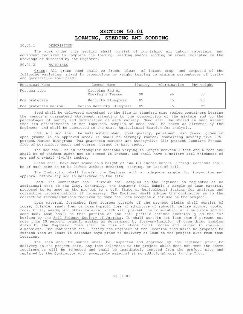
SECTION 50.01 LOAMING, SEEDING AND SODDING
50.01.1 DESCRIPTION
The work under this section shall consist of furnishing all labor, materials, and equipment required to complete the loaming, seeding and/or sodding on areas indicated on the Drawings or directed by the Engineer.
50.01.2 MATERIALS
Grass: All grass seed shall be fresh, clean, of latest crop, and composed of the following varieties, mixed in proportions by weight testing to minimum percentages of purity and germination specified:
Botanical Name Common Name %Purity %Germination %by weight
Festuca ruba Creeping Red or Chewing's Fescue 98 90 50
Poa pratensis Kentucky Bluegrass 85 75 25
Poa pratensis merion merion Kentucky Bluegrass 85 75 25
Seed shall be delivered pre-mixed to the Site in standard size sealed containers bearing the vendor's guaranteed statement attesting to the composition of the mixture and to the percentages of purity and germination of each variety. Seed shall be stored in such manner that its effectiveness is not impaired. Samples of seed shall be taken as directed by the Engineer, and shall be submitted to the State Agricultural Station for analysis.
Sod: All sod shall be well-established, good quality, permanent lawn grass, grown on open ground in an approved area. It shall be strongly rooted, containing seventy-five (75) percent Merion Bluegrass (Poa pratensis merion) and twenty-five (25) percent Pennlawn Fescue, free of pernicious weeds and coarse, burned or bare spots.
The sod shall be in rectangular sections varying in length between 3 feet and 6 feet and shall be of uniform width not to exceed 18 inches. Sod shall have a uniform soil thickness of one and one-half (1-1/2) inches.
Grass shall have been mowed to a height of two (2) inches before lifting. Sections shall be of such size as to be lifted without breaking, tearing, or loss of soil.
The Contractor shall furnish the Engineer with an adequate sample for inspection and approval before any sod is delivered to the site.
Loam: The Contractor shall furnish soil samples to the Engineer as requested at no additional cost to the City. Generally, the Engineer shall submit a sample of loam material proposed to be used on the project to a U.S. State or Agricultural Station for analysis and corrective recommendations if necessary. The Engineer shall advise the Contractor as to the corrective recommendations required to make the loam acceptable for use on the project.
Loam material furnished from sources outside of the project limits shall consist of loose, friable, sandy loam or loam topsoil free of admixture of subsoil, refuse stumps, roots, rock, brush, weeds, and other material which will prevent the formulation of a suitable sod or seed bed. Loam shall be that portion of the soil profile defined technically as the "A" horizon by the Soil Science Society of America. It shall contain not less than 6 percent nor more than 20 percent organic matter as determined by loss-on-ignition of oven dried samples drawn by the Engineer. Loam shall be free of stone 1-1/4 inches and larger in over-all dimensions. The Contractor shall notify the Engineer of the location from which he proposes to furnish loam at least 15 calendar days prior to delivery of loam to the project site from that location.
The loam and its source shall be inspected and approved by the Engineer prior to delivery to the project site. Any loam delivered to the project which does not meet the above requirements will be rejected and shall be immediately removed from the project site and replaced by the Contractor with acceptable material at no additional cost to the City.
50.01-01
When loam is not furnished from outside sources, the material used shall be the loam stripped during the course of excavation on the project site. All roots, stumps, debris, pavement, brush sods and other objectionable materials shall be removed by the Contractor prior to its use.
Chlordane: Chlordane shall be a commercial product in dry powder form, of recent manufacture, delivered to the Site in original unopened containers bearing the manufacturer's guaranteed statement of analysis giving the percent of active ingredient.
Commercial Fertilizer Commercial fertilizer shall be a complete fertilizer and a standard product complying with Federal and State Fertilizer laws. It shall be uniform in composition, dry, free flowing, and shall have been stored in a weatherproof place in such a manner that its effectiveness is not impaired. Fertilizer which becomes caked or otherwise damaged, making it unsuitable for use, shall not be accepted. Commercial fertilizer shall be delivered to the Site in original, unopened containers showing weight, analyses, and name of manufacturer and shall contain the following percentages of weight, of which at least fifty (50) percent of the nitrogen will be derived from an organic material or a composition containing "uramite".
The Contractor shall submit to the Engineer, the manufacturer's guarantee statement of analysis or a manufacturer's certification of compliance covering analysis for the Engineer's written approval before delivery to the Site. Commercial fertilizer shall contain the following ingredients:
A. Nitrogen - derived from:
Methylene urea containing thirty-eight (38) percent or more of insoluble nitrogen ("uramite" or equally approved). Activated sewage sludge containing a minimum of six (6) percent nitrogen (Milorganite or equally approved).
B. Phosphorus - derived from:
Superphosphate containing sixteen (16) to twenty (20) percent phosphoric acid.
Raw bone meal containing twenty (20) to twenty-five (25) percent phosphoric acid and three (3) to four (4) percent nitrogen.
C. Potash - derived from:
Muriate or potash containing approximately sixty (60) percent potassium.
Commercial fertilizers shall contain the following proportions of ingredients for application to new lawns and sod:
Nitrogen.......5 Phosphorus....10 Potash........10
Lime: Lime shall be an approved dolomitic agricultural ground lime-stone, (calcium carbonate) and shall contain not less than eighty five (85) percent of total carbonates, (total carbonates shall be considered as calcium carbonate). Lime-stone shall meet the following graduation requirements: at least fifty (50) percent will pass through a two hundred (200) mesh sieve, ninety (90) percent will pass through a one hundred (100) mesh sieve, one hundred (100) percent will pass through a ten (10) mesh sieve. It shall have been stored in a weatherproof place, in such a manner that its effectiveness is not impaired. Ground limestone shall be delivered to the Site in original, unopened containers bearing the manufacturer's guaranteed statement of analysis.
50.01.3 CONSTRUCTION METHODS
All lines and grades required for proper performance of work shall be established by the Contractor in the field and shall meet with the Engineer’s approval. Commencement of work shall not begin without the written approval of the Engineer.
Planting Seasons Planting shall progress only under favorable weather conditions during the proper season for such work. Unless otherwise authorized in writing by the Engineer the following shall apply: Grass seed and sod shall be placed only between August 15th and October 15th or only between April 1st and May 15th.
50.01-02
Preparation of Subgrade Subsoil shall be graded and uniformly compacted to a true smooth slope nine (9) inches below, and parallel to, the proposed finish grade for areas to be seeded or sodded.
Subgrade shall be loosened to a depth of two (2) inches to four (4) inches. Subsoil shall be kept in a loosened condition until the loam is spread. Subgrade shall be inspected and approved by the Engineer before placing of loam.
Placing and Spreading of Loam: Loam shall be placed and spread, compacted and otherwise manipulated, over approved areas to a sufficient depth so that after natural settlement and light rolling, the completed work shall conform to the lines, grades and elevations shown on the Drawings or directed by the Engineer.
After loam has been spread, it shall be carefully prepared by scarifying or harrowing and hand raking. The whole surface shall then be rolled with a hand roller weighing not more than one hundred (100) pounds per foot of width. All depressions caused by settlement as a result of rolling shall be filled with additional loam and the surface regraded and re-rolled until it presents a smooth, even finish to the required grades.
Application of Lime Prior to completion of loam preparation, and if recommended as a result of soil analysis, lime shall be evenly distributed and thoroughly worked into the top three (3) inches of loam at the rate recommended by the soil analysis laboratory. Limestone shall be applied at least seven (7) days before applying fertilizer and chlordane. The ph content of the loam shall be 6.0 to 7.0 before sod or seed is placed.
Application of Fertilizer Commercial fertilizers shall be uniformly applied in all new grass areas. The application shall be within one week prior to placement of sod, or seed at the rate recommended by the soil analysis laboratory, and worked lightly into the top two (2) inches of loam. Grass areas shall be watered thoroughly after the application of fertilizers.
Application of Chlordane After completion of grading, but prior to delivery of sod, five (5) percent chlordane dust shall be applied at the rate of three and one half (3-1/2) pounds per one thousand square feet (1,000) of grass area, and raked into the top one half (1/2) inch of soil. Chlordane shall be evenly distributed and the entire area thoroughly watered during or immediately after the application. Manufacturer's directions shall be followed.
Sowing of Seed Seeding shall be done on dry or moderately dry soil, and at times when wind does not exceed a velocity of five (5) miles per hour. Seeding shall be done in two directions, at right angles, in such a manner that a uniform stand shall result. Seed shall be sown evenly by hand, or with an approved mechanical spreader, to a depth not exceeding one-fourth (1/4) inch, at the rate of five (5) pounds per one thousand (1000) square feet of area. After seeding the surface shall be evenly and lightly raked with a fine wood-toothed rake or other approved method, and rolled in both directions with a hand roller weighing not more than one hundred (100) pounds per foot of width, and then watered thoroughly with a fine spray. Light sprayings shall be continued as required until grass has become established. The Contractor shall take necessary precautions to keep the area undisturbed until grass is established.
Placing Sod All sod must be delivered to the job within 24 hours after being cut and shall be installed within 36 hours after being cut. Sod shall arrive in a moist condition, free of insects, disease, burned or bare spots, and with root systems having sufficient soil to cover the fibrous roots.
While in temporary storage sod shall be placed in layers with grass to grass and roots to roots. The stacks or piled layers shall be sprayed with water and covered with moist burlap. Particular care shall be exercised in digging, stacking, handling, and replanting, and no sod found in an unsatisfactory condition shall be installed.
Sod shall be placed so that no voids occur between strips and shall be immediately tamped or rolled to an even surface true to finished grade, smooth, even and equally firm at all points. Well-screened loam shall be lightly spread over the sodded area and raked or brushed over the surface. The Contractor shall then thoroughly water to a depth of six (6) inches every twenty-four (24) hours, or as necessary until sod is established.
50.01-03
The Contractor shall protect and maintain new grass areas until final acceptance by proper watering, mowing, raking, weeding, edging, repairing sunken areas or washes, replanting and all incidental work, necessary to establish a uniform, healthy stand of specified grasses in all areas required. After grass has started, all areas and parts of areas which fail, for any reason, to show a uniform stand of grass, shall be re-sodded or be seeded repeatedly by the Contractor until all areas are covered with a satisfactory stand of grass of the varieties specified. The Engineer shall determine when a uniform, healthy grass area is established. There shall be no final acceptance of grass areas prior to ninety (90) of placing sod of seed. 50.01.4 METHOD OF MEASUREMENT Measurement for payment for loaming, seeding and sodding shall be made by the Engineer and shall be the actual area of sodding or seeding in accordance with the limits and dimensions shown on the Contract Drawings or directed by the Engineer, and in accordance with these Specifications. Payment Limits for areas Disturbed by Sewer Work
Payment lines shall be width of actual placement of sod or seed except that in no case shall the width between payment lines be more than the following:
a. For pipe-arches, sewers, service laterals, and underdrains, 12 feet greater than the
nominal horizontal inside dimension of pipe where such dimension is less than 36 inches. b. For the same types of pipe-arches 13 feet greater than the nominal horizontal inside
dimension of the pipe where such dimension is 36 inches or greater. Payment Limits for Other Areas Payment lines shall be the length and width of actual placement of sod or loam and seed except that in no case shall said length and width between payment lines be more than that shown on the Drawings or directed by the Engineer. 50.01.5 BASIS OF PAYMENT Payment for this work will be made at the contract price bid per square yard for "Sodding" or the contract price bid per square yard of "Loaming and Seeding" as measured and approved for payment by the Engineer. The contract unit prices shall include the cost of all labor, materials, equipment, transportation and incidentals necessary to complete this item in accordance with the Drawings and Specifications and to the satisfaction of the Engineer. When no item for "Loaming, Seeding and Sodding" appears in the proposal, the cost of this work shall be included in the various contract unit prices.
50.01-04
SECTION 50.02 FURNISH AND PLACE TOPSOIL
50.02.1 DESCRIPTION
This work shall consist of furnishing, placing and shaping topsoil in the areas and to the depth shown on the Drawings or as directed by the Engineer.
50.02.2 MATERIALS
1. Topsoil shall contain not less than three (3) nor more than twenty (20) percent organic matter as determined by loss on ignition of over-dried samples drawn by the Engineer.
2. The following textural classes, as determined on the basis of material passing the 20-mesh sieve and subjected to partial mechanical analysis, shall be acceptable.
-Loamy sand, with not more than 80 percent sand -Sandy loam -Loam -Sandy clay loam, with not more than 30 percent clay -Silt -Loam, with not more than 60 percent silt
3. The topsoil shall be loose, friable, reasonably free of admixtures of subsoil, free from refuse, stumps, roots, brush, weeds, rocks and stones 1-1/4 inch in overall dimensions. The topsoil shall be also free from any material that will prevent the formation of a suitable seedbed or prevent seed germination and plant growth.
4. The topsoil and its source shall be inspected and approved by the Engineer before the material is delivered to the project site. Any material delivered to the site which does not meet specifications, or which has become mixed with undue amounts of subsoil during any operation at the source or during placing or spreading, will be rejected and shall be replaced by the Contractor with acceptable material at his own expense.
50.02.3 CONSTRUCTION METHODS
The areas on which topsoil is to be placed shall be graded to a reasonably true surface. Topsoil shall then be spread and shaped to the lines and grades shown on the Drawings or as directed by the Engineer. The depth indicated on the Drawings to which topsoil is to be placed is that required after settlement of the material has taken place. All stones, roots, debris, sod, weeds or other undesirable material shall be removed. After shaping and grading, all trucks and other equipment shall be excluded from the topsoil area to prevent excessive compaction. The Contractor shall perform such work as required to provide a friable surface for seed germination and plant growth prior to seeding.
During hauling and spreading operations, the Contractor shall immediately remove any material dumped or spilled on the shoulders or pavement.
It shall be the Contractor’s responsibility to restore to the line, grade and surface all eroded areas with approved material and to keep topsoiled area in acceptable condition until the completion of the construction work.
50.02.4 METHOD OF MEASUREMENT
This work will be measured for payment by the number of square yards of area on which the placing of topsoil has been completed and the work accepted.
50.02.5 BASIS OF PAYMENT
Payment shall be made at the contract unit price per square yard, which price shall include all labor, materials, and equipment incidental thereto.
50.02-01
SECTION 50.03 PLANTING
50.03.1 DESCRIPTION
The work under this section shall consist of furnishing all labor, materials, apparatus and equipment required to complete the planting as indicated, in strict accordance with the Specifications and applicable Drawings, and subject to the terms and conditions of the Contract. This work shall include, but not be limited to, the following:
1. Submitting samples and analyses for approval.
2. Preparation of plant pits and beds including excavating, removing unsuitable subgrade material and backfilling of all planting areas with specified planting mixture.
3. Furnishing all plant materials shown on the Drawings, planting, and all necessary planting operations; including watering, staking, guying, wrapping, fertilizing, spraying, mulching, weeding, pruning, and protection of roots.
4. Protecting, maintaining, guaranteeing and replacing plant materials and related items.
50.03.2 QUALITY ASSURANCE
1. Nomenclature
The scientific and common names of plants herein specified conform with the approved names given in Standardized Plant Names (1942 Edition), prepared by the American Joint Committee on Horticultural Nomenclature. The names of varieties not included therein generally conform with names accepted in the nursery trade.
2. General
The species, scientific and common names, sizes, quantity, and manner in which to be furnished shall be listed on the Drawings. All plant materials shall conform to the requirements of the Plant List and Specifications and shall be true to the botanical names and standards of size, culture and quality for the highest grades and standards, in conformance with the “American Standard for Nursery Stock”, by the American Association of Nurserymen, Inc. ANSI Z60.1-1990) All plants shall be grown in accordance with good horticultural practice, and under climatic conditions similar to those existing in New Haven, Connecticut (Zone 6) for at least two (2) years prior to date of planting of this Contract.
Collected stock from native stands or established plantings shall be planted only if so designated in the Plant List and approved in writing by the Engineer. Collected stock shall meet requirements of the American Association of Nurserymen and these Specifications. Each bidder shall investigate sources of supply and shall be certain before submitting his bid, that he can supply all plant materials named on the Plant List in the size, variety, quality and quantity required. Failure to take this precaution shall not relieve the successful bidder from the responsibility of furnishing all plant materials, in strict accordance with contract requirements and without additional expense to the City.
3. Quality
All plant materials shall be nursery-grown and freshly dug from favorable locations in a subgrade, which insures vigorous growing, plants with heavy, and fibrous root systems. All plants shall be legibly tagged with the proper name and shall have a habit of growth, which is normal for the species or variety. All plants furnished shall have a good healthy, well-formed upper growth, well branched, well proportioned, and densely foliated when in leaf. All plants shall be in a sound, healthy, vigorous condition, free from objectionable parasites, insects, eggs or larvae, scale, plant diseases and injuries, with all parts moist and showing active green cambium when cut. Plants lacking compactness or proper proportions, and plants injured by too close planting in nursery rows, shall not be accepted. Plants used where uniformity is required shall be matched as closely as possible.
a. Specimens. The Engineer shall inspect all plant materials indicated as “Specimens” at the place of growth for conformity to specific requirements. Landscape specimens shall be of extra heavy grade and shall be selected for shape, proportion, symmetry if applicable) arrangement of trunks or branches, and character and effect in general, for a particular grouping or location.
b. Trees. The Engineer shall inspect all trees, at the place of growth for conformity to specific requirements. All trees shall be selected for shape, proportion symmetry, branching, habit, character and effect in general for a particular grouping or location. Unless a tree clump is designated, the trunk of each tree shall consist of a single trunk growing from a single, unmutilated crown of roots. All trees shall not be damaged or cut and shall be free from sun scald, frost, cracks, dead wood, or wounds resulting from abrasion, fire or other cause. Trees shall have straight trunks with leaders intact and those trees which have had their leaders cut or so damaged that cutting is necessary shall not be accepted. All old abrasions and cuts shall be completely calloused over. Pruning
PLANTING 5003-1
wounds shall not exceed one (1) inch in diameter and such wounds shall show vigorous bark on all edges.
1. Deciduous trees shall be free of branches to a point not more nor less than approximately sixty (60) percent of their height unless otherwise indicated on the Drawings. Height of branching shall bear a relationship to the size and kind of tree with the crown of the tree having good balance with trunk. 2. Evergreen trees shall be full, bushy, compact, symmetrical plants of uniform color and texture displaying active growth on all parts. Side branches shall possess thick, closely massed foliage of fine texture and leafage to the ground.
B. DEFINITIONS AND ABBREVIATIONS (Continued)
3. Cal.: caliber measurement of tree trunk. 4. Ht.: height of plant.
5. Spd.: spread of plant. 6. B&B: balled and burlapped plants.
7. B.R.: bare root plants. 8. City: New Haven, Connecticut 9. Site: construction areas within project limit lines. 10. Finished grades: proposed final grades. C. SAMPLES, ANALYSES AND TESTS
1. Analyses and tests of materials shall be made in accordance with the current methods of the Association of Official Agricultural Chemists.
2. Certified analyses by a recognized laboratory of topsoil, peat moss, fertilizer, manure, insecticides, fungicides, chemical weed killers, etc., shall be submitted by the Contractor, at his expense, if requested by the Engineer the Engineer's written approval, before delivery to the Site. Packaged and sealed standard products accompanied by manufacturer or vendor's analyses and complying with Specification requirements shall be acceptable. 3. Specifications shall accompany all materials to be analyzed and tested so that comparisons and recommendations by the laboratory may be made. Should amendments be necessary, the laboratory's recommendations shall be forwarded to the Engineer. 4. Approval of materials shall not be construed as final acceptance, and the Engineer reserves the right to analyze, for comparison with Specification requirements, any or all materials delivered for use under this Contract. The cost of such tests shall be borne by the City of New Haven. Should these tests indicate non-compliance with Specifications, the City shall charge the entire cost of such tests to the Contractor, and all rejected material shall be removed from the Site and replaced with acceptable material at the Contractor's expense.
c. Shrubs: All shrubs shall be full, bushy, compact, symmetrical plants of uniform color and texture. Side branches shall possess thick, closely massed foliage to the ground.
d. Hedges All hedges shall be comprised of full, bushy, compact, plants of uniform color, texture, and quality possessing thick closely massed branches and foliage to the ground. Plants in hedgerows shall be uniform in all respects with individual plants equally spaced to form a continuous unbroken line.
e. Ground Covers - All plant materials specified as ground covers shall be number one (1) grade plants. Tops shall be heavy and well branched and root systems vigorous and well developed. Ground cover plants shall have been established in containers for a minimum of one (1) growing season and shall exhibit a well-rooted or "pot-bound" condition at the time of planting. f. Vines. All vines shall be number one (1) grade plants with heavy, well-branched tops and vigorous well-developed root systems in proportion to the tops. All vines shall be attached by an approved method to nearest vertical surface indicated on the Drawings.
g. Bulbs, Corms, and Tubers - All bulbs, corms and tubers shall be fresh, healthy, clean of latest crop, and shall have been stored in such a manner that their effectiveness is not impaired. All bulbs, corms and tubers shall have a normal growth for the species and shall be in a sound healthy, vigorous, free flowering condition one season after planting.
PLANTING 5003-2
4. Preparation of Plant Materials Balled Plants - Plants designated "B&B" in the Plant List shall be moved as solid units with firm, natural balls of soil securely wrapped with burlap. The diameter and depth of the ball of soil must be sufficient to encompass the fibrous and feeding root system necessary for the healthy development of the plant as set forth in Horticultural Standards. Collected plants shall be balled and burlapped at least ten (10) percent greater in diameter than specified for in nursery-grown stock. A plant shall not be accepted when the ball of earth surrounding its roots has been badly cracked or broken preparatory to, or during the process of, planting or after the burlap, staves, ropes or platforms required in connection with its transplanting have been removed. The plant and its ball of soil shall remain intact as a unit during all operations. Burlap for balling plants shall be of jute and shall weigh not less than seven and two-tenths (7.2) ounces per square yard. Substitute cloths, if approved in writing by the Engineer, shall have a strength and resistance to tearing equal to the jute specified above. Balled and burlapped plants shall be firmly wrapped and bound with twine, cord, or wire mesh and, if necessary, the ball shall be secured to a platform to prevent cracking or breaking during the progress of planting and transportation.
a. Bare Root Plants - Plants designated "B.R" in the Plant List shall be moved when dormant, and surrounding earth shall be removed without injury to the root system. Such plants shall have heavy, fibrous root systems, developed by proper cultural treatment, transplanting, root pruning, and other requirements necessary for healthy development of the plant. The major portion of a fibrous root system and of all main roots necessary for healthy development of each plant shall be preserved. Immediately after digging, all roots shall be covered with a thick coating of mud by puddling or wrapping in wet straw, moss or other suitable packing material, to prevent drying out. The spread of roots of bare root collected plants shall be one-third (1/3) greater than that of nursery-grown plants. b. Container-Grown Plants - Plant materials designated on the Plant List to be in pots, cans, tubs, flats or boxes shall be considered container-grown plants. Each container shall be of adequate size for its plant material(s) and the plant shall have a sufficient root system to hold earth intact after removal without being "root bound". These plants shall be acclimated to outside conditions (Zone 6) and shall be equal to, and acceptable for, field-grown stock.
5. Plant Measurements - All plant materials shall conform to the measurements specified in the Plant List, which is the minimum size acceptable for each variety. Plants shall be measured before pruning, with branches in normal position. Plant materials specified to be furnished in a size range shall be a fair average of the minimum and maximum sizes specified. Plants larger in size than specified shall be used with the approval of the Engineer, but such a use will make no change in the Contract Price. If the use of larger plants is approved, the ball of earth, container, or spread of roots, shall be increased proportionately. Pruning of branches to obtain the required height or spread shall not be allowed. a. Trees - The height of trees shall be measured from the crown of roots to the tip of the top branch and the caliber measurement shall be taken twelve (12) inches above finished grade.
b. Shrubs - The height and spread measurements of shrubs shall be the average of the main body of the plant and not from the greatest dimension(s).
c. Ground Covers & Vines - Measurements for ground cover, plants and vines shall equal or exceed American Association of Nurserymen standards in all ways according to age, grade, size of clump, length and number of runners, and any other characteristics peculiar to a particular species.
d. Bulbs, Corms, & Tubers - Sizes and grades for bulbs, corms and tubers shall conform to American Association of Nurserymen standards. 6. Substitutions - Acceptance of this Contract carry with it the assumption that the Contractor is able to supply all plant materials indicated in the Plant List, on the Drawings and as specified. Substitutions shall not be permitted except at the specific request of the Engineer, or when proof is submitted that a particular plant material is not obtainable after all sources to supply have been investigated. If the Contractor is not able to supply specific plant materials or sizes according to these Specifications, a proposal shall be considered for use of nearest equivalent size or variety, with an equitable adjustment of Contract Price. The Engineer shall approve substitutions in writing. When the Engineer locates sources for plant materials, there shall be no substitutions, and those sources shall be used.
PLANTING 5003-3
7. Initial Inspection of Plant Materials - Within thirty (30) days following acceptance of the bid, the Engineer shall be notified of the source(s) of plant materials. Plant materials shall be inspected, selected, and tagged for identification by the Engineer, with the Contractor, prior to digging and/or moving. Inspection of plant materials by the Engineer shall be for quality, size, shape, color, and variety only. Inspection for size of ball or root systems latent defects, and other requirements that may be specified shall be made at the Site during progress of work. No plant shall be dug up or delivered to the Site until the initial inspections under the Engineer's direction have been made and approved. Plant materials shall be subject to refusal at any time and inspection and approval of plant materials at the place of growth shall not in any way waive the Engineer's right of rejection.
50.03.3 GENERAL MATERIALS Materials required to complete the planting and landscaping indicated on the Drawings should conform to the requirements of these Specifications. Substitutions shall not be permitted except at the specific request, and upon written approval of the Engineer. 1. Topsoil - Topsoil shall meet the requirements of Section 5002 2. Peat Moss - Peat moss shall be a domestic product, consisting of partially decomposed
vegetable matter of a natural occurrence, of either reed or sedge peat, dark brown to black in color, and free of lumps, roots, stones, decomposed colloidal residue, wood, sulfur, iron, fungi, insect life, diseases, and any toxic substances harmful to plant growth, with an ash content not exceeding ten (10) percent. It shall be finely shredded or granulated material, suitable for horticultural uses, and shall have been conditioned after excavation by storage in stockpiles for at least one (1) year prior to its use. Its texture may vary from porous-fibrous to spongy-fibrous, and either crumbly or compact, but reasonably elastic, with particles not exceeding one half (1/2) inch in size, and of such character as not to be displaced by wind. Its acidity range shall be pH 5.0 to pH 7.0 and the maximum moisture content shall be seventy (70) percent by weight. Organic matter shall test at least eighty-five (85) percent on a dry weight basis. Water absorbing ability shall be one hundred and fifty (150) to three hundred and fifty (350) percent. Peat Moss shall be delivered to the site in an air-dry condition, containing not more than thirty-five (35) percent moisture by weight, and with the fibrous and cellular contents recognizable.
3. Manure - Manure shall be a well-rotted, unleached stable manure, not less than eight (8) months and not more than two (2) years old. It shall be free from seeds, weeds, sawdust, shavings, or refuse of any kind, and shall not contain over twenty-five (25) percent straws.
A composition of peat moss or peat humus, to which has been incorporated dehydrated manure such as "Bovung of Spurzon" in the proposition of two hundred (200) pounds of dehydrated manure per one thousand (1000) square feet of peat, may be substituted for manure as specified above.
4. Fertilizers A. “Unique Feeder” Fertilizer Packets, as furnished by Unique Fertilizers, Inc., Deptford, NJ
(1-609-848-4444). 1. Controller-release 16-8-16 analysis fertilizer contained in polyethylene
perforated bags with micropore holes. Bag shall contain 4 ounces minimum of water-soluble fertilizer to be effective for 8 years.
B. “Agriform 20-10-5 Planting Tablets” as manufactured by Grace-Sierra Horticultural
Products Co., Milpitas, CA (1-408-263-8080). 1. 5 gram (weight) tablet. 2. Tightly compressed slow release plant food with the following guaranteed
analysis: TOTAL NITROGEN (N)* ..................................20% 7% Water Soluble Nitrogen 13% Water Insoluble Nitrogen AVAILABLE PHOSPHORIC ACID.............................10% SOLUBLE POTASH ....................................... 5% CALCIUM ............................................ 2.6% SULFUR ............................................. 1.6% IRON ...............................................0.35%
PLANTING 5003-4
* 17% slowly available nitrogen from ureaformal dehyde.
Derived from urea-formaldehyde, calcium phosphates, potassium sulfate, calcium sulfate, and ferrous sulfate.
C. 5-10-10 fertilizer: commercial grade fertilizer, free flowing and uniform in
composition. Provide granular fertilizer conforming to Federal Commercial Item Description A-A-1909, Type 1, Class 2, and bearing the manufacturer’s guaranteed statement of analysis. Granular fertilizer shall contain a minimum percentage by weight 5% nitrogen of which 50% shall be organic, 10% available phosphoric acid and 10% potash.
5. Lime - Lime shall be approved dolomitic agricultural ground limestone, (calcium carbonate) and shall contain not less than eighty-five (85) percent of total carbonates, (total carbonates shall be considered as calcium carbonate). Limestone shall meet the following graduation requirements: at least fifty (50) percent will pass through a two hundred (200) mesh sieve, ninety (90) percent will pass through a one hundred (100) mesh sieve, one hundred (100) percent will pass through a ten (10) mesh sieve. It shall have been stored in a weatherproof place, in such a manner that its effectiveness is not impaired. Ground limestone shall be delivered to the site in original, unopened containers bearing the manufacturer's guaranteed statement of analysis.
6. Mulches - Mulches shall be suitable for horticultural uses and shall be free from
insects, scale, diseases, fungi, seeds, soils, admixtures, refuse, sticks, and other deleterious materials and shall be of such character as not be displaced by wind. They shall be clean, of uniform quality and texture and shall not contain any toxic substances harmful to soils and plant materials. Mulches shall have been stored in such a manner that their effectiveness is not impaired and those, which become caked, or otherwise damaged, making them unsuitable for use, shall not be accepted.
1. For saucers and planting beds; shall be double shredded softwood barkmulch
composed primarily of hemlock and spruce bark. Sample to be approved. 2. For winter cover: shall be salt marsh hay. 7. Water - Water for all planting purposes shall be free of oil, acid, alkalis, salts, and
other substances harmful to plant life. The Contractor shall at his expense, make arrangements necessary to ensure an adequate supply of water to meet the needs of this Contract. He shall furnish all necessary hose, equipment, attachments and accessories for the adequate irrigation of all planting and landscaping areas as shall be required to complete the work specified.
8. Wrapping Material - Tree Wrapping Material: six-inch wide heavy duty, untreated burlap
tree wrap as supplied by Good Prod. Sales, Inc., Kenilworth, New Jersey, (201) 245-5055 or approved equal. Twine for tying to be not less than 2-ply jute.
9. Super absorbent Polymer: “Terra-Sorb AG” as supplied by Industrial Services
International, Inc., Brandenton, FL (800)227-6728. a. Shall be crossliked acrylanide copolymerized with sodium or potassium
acyrlate. Diaper type acrylate superabsorbent polymers are not acceptable. b. Capable of absorbing 300-400 times its weight in water. c. Engineered to remain effective in the soil from 3 to 4 years, minimum. 10. Sulfur: Commercial or flour sulfur, unadulterated and delivered in containers with
the name of the manufacturer, material, analysis and net weight appearing on each container.
11. No Item 11. 12. Friction Guards - Friction Guards for preventing damage to bark from supporting wires
shall be a minimum of two (2) ply reinforced fabric bearing black rubber hose, not less than three-fourths (3/4) inch in diameter.
13. Stakes - Stakes for supporting trees shall be of sound wood, capable of standing in
the ground for at least one (1) year. Squared lumber or round poles shall be used in the sizes specified or indicated on the plant detail drawing.
PLANTING 5003-5
14. Guy Wires - Guy wires for supporting trees shall be a minimum of two twisted strands of twelve (12) gauge pliable, galvanized wire, or as otherwise specified on the Drawings.
15. Markers - Markers to be fastened to guy wires shall be of sound wood approximately
one-half (1/2) inch by two (2) inches by five (5) inches with a three-eighths (3/8) inch hole centered one (1) inch from the end. Markers shall be painted white.
16. Anti-desiccant - Wilt-Purf, or Vaporguard, an emulsion that shall provide a protective
coating over plant surfaces, shall be applied to reduce moisture losses in transplanting and to preserve new planting. It shall dry to a colorless, harmless, non-staining, slightly glossy film that shall wear away completely in approximately three (3) months. Wilt-Pruf shall be delivered to the site in original unopened containers bearing the manufacturer's name and guarantee statement of analysis. "Wilt-Pruf" manufactured by Nursery Specialty Products, Incorporated, New York, New York or “Vaporguard” as manufactured by Miller Chemical and Fertilizer Corporation, Hanover, Pennsylvania, or a product of approved equal quality shall be acceptable.
17. Commercial Wood Dressing - Commercial tree wood dressing, shall be an effective wound
dressing of asphaltum paint, suitable for horticultural uses. Paint shall be a waterproof, adhesive and elastic antiseptic free of kerosene, coal tar, creosote and any other chemical harmful to plant tissues, and of such quality as to protect wood against insects, fungus, and rotting. It shall be approved by the Engineer and delivered to the site in original unopened containers bearing the manufacturer's name and guarantee statement of analysis. 18. Disease and Pest Controls - Chemicals used to control disease and insects shall be effective, shall provide quick and lasting results, and shall not do any damage to plant materials or have any ill effects upon soils. Toxic and poisonous chemicals, which may present health hazards to humans and animals, shall not be used. Chemicals shall not be flammable, shall not burn foliage and roots, and shall not volatilize and form vapors, which may cause damage. All chemicals shall be stored in such a manner that effectiveness is not impaired and shall spread uniformly and adhere well to foliage, when applied.
Contact or stomach poisons shall be used for insect control. A mixture containing a fungicide, a milicide, and control for both sucking and chewing insects shall be used only if ingredients are compatible. Chemicals shall be used with discretion so as not to harm plant materials or become ineffective during the period required. Disease and pest controls shall be delivered to the site in sealed containers bearing the manufacturer’s guarantee statement attesting to mixtures and percentages of each chemical subject to the approval of the Pure Food and Drug Administration, the U.S.D.A., the State Agricultural Station and the Engineer, who shall give written approval before any chemical is used.
19. Guy Wire Flags: shall be plastic, color - orange, min 2” x 8”.
20. Root Barrier: shall be UB24-2, 24” x 24” panels, as manufactured by Deep Root, San Francisco, CA (800) 458-7668. Local Distributor: East Haven Landscape Products (203) 467-6260.
21. Weed Barrier: shall be Typar Landscape Fabric as manufactured by Reemay Inc., Nashville, Tennessee, (800) 367-9556 or approved equal. Local Distributor: North Haven Landscape Products (203) 467-6260.
50.03.3 CONSTRUCTION METHODS A. GENERAL - All planting shall be performed by personnel familiar with planting
procedures under the supervision of a qualified planting foreman, and in accordance with the Drawings and Specifications. Rollers, bulldozers, trucks or any other heavy equipment shall not be permitted to pass over underground utilities, heating and electric conduits, etc. All trench or grade stakes set by others shall be maintained until the Engineer approves their removal. The furnishing and planting of any plant materials shall be interpreted to include; excavating, the digging of holes, provision of soil planting mixture, sand, mulch, fertilizer, and lime, (if recommended by the proper Agricultural Agent, State Laboratory and/or Engineer, after tests of a typical loam sample), furnishing at the proper time or year a plant of the specified size with its roots in the specified manner, the labor of planting, guying or staking, pruning, wrapping, watering, spraying, maintaining, replacing, guaranteeing and all other necessary incidental work in accordance with the Plans and Specifications to the satisfaction of the Engineer. All plants shall be inspected and approved at the site by the Engineer before excavation and planting. Rejected material shall be immediately removed from the site and replaced with acceptable
PLANTING 5003-6
material at no additional cost to the City. Existing topsoil shall be used only if approved by the Engineer.
B. PLANTING SEASONS - Planting shall progress only under favorable weather conditions, during the proper season for such work, and in accordance with local accepted practice. Planting shall not be permitted when ground is frozen or extremely moist. At the option of and on responsibility of, the Contractor, planting may start earlier or continue later than specified without additional compensation, subject to approval of the Engineer, regarding time of work and methods of operation.
1. Evergreen Plants shall be planted in the spring, until the time when new growth
begins to take place, and from September 1 to October 30. 2. Planting Schedule: a. Contractor shall submit planting schedule indicating proposed nursery sources and
anticipated installation schedule to the Engineer for review and approval. b. Planting schedule shall be submitted at the same time as overall construction
program/scheduling. c. Schedule the dates for each type of landscape work during normal seasons for
such work in each area of the site. Correlate with specified maintenance periods to provide maintenance until acceptance by the Engineer. Once accepted, revise dates only as approved in writing, after documentation of reasons for delays.
d. Coordinate with approved nurseries to secure and confirm installation dates
of all plant material after Engineer’s acceptance of planting schedule. C. LOCATION - Trees, shrubs, and vines are shown on the Planting Plans with an identifying
symbol marking the position of each plant. The number of ground cover plants and bulbs in each planting bed is indicated, spacing to be adjusted on the ground. Locations for all plant materials and outlines for planting areas shall be staked or marked on the ground, and shall be approved by the Engineer before excavation and planting is started. Adjustments in locations and outlines shall be made as directed by the Engineer without additional charge.
D. CARE OF EXISTING PLANTING -Existing trees, shrubs, planting beds, grass areas, pavement and curbs in areas near construction shall be effectively protected during construction operations, by boxing or planking. Any necessary grading or digging around existing plants shall be done with extreme care to prevent damage to roots. Barricades and other devices used to protect existing planting shall be removed only after all construction is completed. Any damage caused by planting operations to existing materials or improvements on or adjacent to the site is the responsibility of the Contractor, and shall be promptly repaired at the direction of the Engineer, and at the Contractor's expense.
E. OBSTRUCTIONS - All planting areas have been inspected and it is not contemplated that
any planting shall be done where there are below ground or overhead obstructions or where impervious soil will require supplementary drainage.
1. Prior to excavation of planting areas or plant pits, or to driving of placing of stakes, the Contractor shall ascertain the location of all location of all electric cables, conduits, utility lines, oil tanks, and supply lines, so that proper precautions shall be taken not to disturb or damage any sub-surface improvements. If any are encountered the Contractor shall promptly notify in writing, the Engineer, who shall arrange to relocate the plant material. 2. When the plant pits are dug the Contractor shall place water in the pit to determine that the plant pits are free draining. If the plant pits are not free draining then the Engineer shall be notified immediately before proceeding with plant installation. 3. If ledges, stones, boulders, foundations, or other obstructions are encountered and cannot be broken and removed by hand in the course of digging plant pits of the specified size, the Contractor shall promptly notify the Engineer, who may designate other locations for the plant materials. Where locations cannot be changed obstructions shall be removed to a depth of not less than one (1) foot below the required pit depth. 4. Repairs to damages incurred, relocation of plant materials and removal of rock or underground obstructions encountered shall be made at the Contractor’s expense and only as directed by the Engineer. Failure to follow these procedures places upon the
PLANTING 5003-7
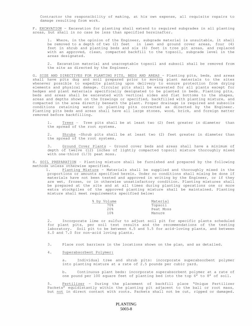
Contractor the responsibility of making, at his own expense, all requisite repairs to damage resulting from work.
F. EXCAVATION - Excavation for planting shall extend to required subgrades in all planting
areas, but shall in no case be less than specified hereinafter.
1. Where, in the opinion of the Engineer, subgrade material is unsuitable, it shall be removed to a depth of two (2) feet in lawn and ground cover areas, four (4) feet in shrub and planting beds and six (6) feet in tree pit areas, and replaced with an approved, clean, compacted backfill to the topsoil, subgrade level in the areas designated.
2. Excavation material and unacceptable topsoil and subsoil shall be removed from the site as directed by the Engineer.
G. SIZE AND DIRECTIVES FOR PLANTING PITS, BEDS AND AREAS - Planting pits, beds, and areas
shall have pits dug and soil prepared prior to moving plant materials to the sites whenever possible to expedite planting upon delivery to ensure protection from drying elements and physical damage. Circular pits shall be excavated for all plants except for hedges and plant materials specifically designated to be planted in beds. Planting pits, beds and areas shall be excavated with vertical sides and flat bottoms to the shapes, areas and depths shown on the Drawings or specified, backfilled with planting mixture, and compacted in the area directly beneath the plant. Proper drainage is required and subsoils conditions retaining water in planting pits corrected as directed by the Engineer. Planting pits beds and areas shall have all large stones, wood, brick, and foreign matter removed before backfilling.
1. Trees - Tree pits shall be at least two (2) feet greater in diameter than
the spread of the root systems.
2. Shrubs -Shrub pits shall be at least two (2) feet greater in diameter than the spread of the root systems.
3. Ground Cover Plants - Ground cover beds and areas shall have a minimum of
depth of twelve (12) inches of lightly compacted topsoil mixture thoroughly mixed with one-third (1/3) peat moss.
H. SOIL PREPARATION - Planting mixture shall be furnished and prepared by the following
methods unless otherwise specified. 1. Planting Mixture - Materials shall be supplied and thoroughly mixed in the
proportions or amounts specified herein. Under no conditions shall mixing be done if materials have not been tested and approved in writing by the Engineer, or if they are wet, frozen, or in otherwise unsatisfactory condition. Planting mixtures shall be prepared at the site and at all times during planting operations one or more extra stockpiles of the approved planting mixture shall be maintained. Planting mixture shall meet requirements specified below:
% by Volume Material 70% Topsoil 20% Peat Moss 10% Manure 2. Incorporate lime or sulfur to adjust soil pit for specific plants scheduled
for plant pits, per soil test results and the recommendations of the testing laboratory. Soil pit to be between 4.5 and 5.5 for acid-loving plants, and between 6.0 and 7.0 for non-acid loving plants.
3. Place root barriers in the locations shown on the plan, and as detailed. 4. Superabsorbent Polymer: a. Individual tree and shrub pits: incorporate superabsorbent polymer
into planting mixture at a rate of 2.5 pounds per cubic yard. b. Continuous plant beds: incorporate superabsorbent polymer at a rate of
one pound per 100 square feet of planting bed into the top 6” to 8” of soil. 5. Fertilizer - During the placement of backfill place “Unique Fertilizer
Packets” equidistantly within the planting pit adjacent to the ball or root mass, but not in direct contact with roots. Packets shall not be cut, ripped or damaged.
PLANTING 5003-8
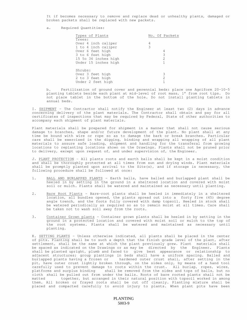
It if becomes necessary to remove and replace dead or unhealthy plants, damaged or broken packets shall be replaced with new packets.
a. Required Quantities: Types of Plants No. Of Packets Trees: Over 4 inch caliper 4 1 to 4 inch caliper 3 Over 6 feet high 4 3 to 6 feet high 3 15 5o 36 inches high 2 Under 15 inches high 1
Shrubs: Over 3 feet high 3 2 to 3 feet high 2 Under 2 feet high 1 b. Fertilization of ground cover and perennial beds: place one Agriform 20-10-5
planting tablets beside each plant at mid-level of root mass, 1” from root tips. Do not place tablet in the bottom of the hole. Do not install planting tablets in annual beds.
I. SHIPMENT - The Contractor shall notify the Engineer at least two (2) days in advance
concerning delivery of the plant materials. The Contractor shall obtain and pay for all certificates of inspections that may be required by Federal, State of other authorities to accompany each shipment of plant materials.
Plant materials shall be prepared for shipment in a manner that shall not cause serious damage to branches, shape and/or future development of the plant. No plant shall at any time be bound with wire or rope so as to damage the bark or break branches. Particular care shall be exercised in the digging, binding and wrapping all wrapping of all plant materials to assure safe loading, shipment and handling for the transferal from growing locations to replanting locations shown on the Drawings. Plants shall not be pruned prior to delivery, except upon request of, and under supervision of, the Engineer.
J. PLANT PROTECTION - All plants roots and earth balls shall be kept in a moist condition
and shall be thoroughly protected at all times from sun and drying winds. Plant materials shall be promptly planted upon arrival to the Site(s), and if storage is necessary, the following procedure shall be followed at once:
1. BALL AND BURLAPPED PLANTS - Earth balls, have balled and burlapped plant shall be
heeled in by setting in the ground in a sheltered location and covered with moist soil or mulch. Plants shall be watered and maintained as necessary until planting.
2. Bare Root Plants - Bare-root plants shall be heeled in immediately in a sheltered
location, all bundles opened, the plants spread out into a forty five (45) degree angle trench, and the foots fully covered with damp topsoil. Heeled in stock shall be watered periodically as required so as to remain moist at all times. Care shall be taken not to wash soil away from the roots.
3. Container Grown plants - Container grown plants shall be heeled in by setting in the
ground in a protected location and covered with moist soil or mulch to the top of the root systems. Plants shall be watered and maintained as necessary until planting.
K. SETTING PLANTS - Unless otherwise indicated, all plants shall be placed in the center of pits. Planting shall be to such a depth that the finish grade level of the plant, after settlement, shall be the same at which the plant previously grew. Plant materials shall be spaced as indicated on the Drawings or as may be directed by the Engineer. Plants shall be planted upright, plumb and faced to give best appearance or relationship to adjacent structures; group plantings in beds shall have a uniform spacing. Balled and burlapped plants having a frozen or hardened outer crust shall, after setting in the pit, have outer crust lightly broken through, on the sides only, by means of a hand tool carefully used to prevent damage to roots within the crust. All burlap, ropes, wires, platforms and surplus binding shall be removed from the sides and tops of balls, but no cloth shall be pulled out from under the balls. Roots of bare rooted plants shall not be matted together, but arranged in their natural position with topsoil worked in among them. All broken or frayed roots shall be cut off cleanly. Planting mixture shall be placed and compacted carefully to avoid injury to plants. When plant pits have been
PLANTING 5003-9
backfilled approximately two thirds (2/3) their depth they shall be watered thoroughly and allowed to settle before installing remainder of soil to top of pit.
Planting mixture shall be tamped around and under the edges of plants and all voids filled. When backfilling is partially done by use of high lift or other mechanical means, extra care shall be taken to ascertain that soil is worked under the ball and around the roots. During all planting operations the prepared planting mixture shall be used in a loose, friable, unfrozen condition. All pits shall be filled to the finish grade level at which the plant previously grew, and wherever possible, to facilitate watering, a shallow saucer shall be formed around each plant by placing a ridge or the planting mixture around the edge of each pit. The saucer shall have a diameter equal to the hole dug for the plant, and, for trees, a depth of six (6) inches; for shrubs four (4) inches. After the ground has settled, additional soil, mulch or paving block shall be used to maintain the finished grades indicated on the Drawings and excess topsoil disposed of as directed by the Engineer.
L. STAKING, GUYING AND WRAPPING OF TREES - All staking, guying anchoring and wrapping
shall be done immediately after planting in accordance with Drawings and Specifications. Stakes shall be set parallel to contours or curbs, driven into the ground to the depth indicated and fastened to the tree with steel wire run through a rubber hose of sufficient length to prevent injury to the tree. All plants shall stand plumb after guying and staking, and any stake or wire that becomes displaced of broken before final acceptance of the work shall promptly be reset or replaced. All staking, guying and wrapping shall be removed at the end of the guarantee period or earlier if so directed by the Engineer.
1. Setting - Trees shall be set plumb and rigidly braced in position until soil has
been tamped solidly around the earth ball. 2. Staking - Staking shall be as shown on the Drawings or as hereinafter
specified. Stakes shall be equally spaced, uniform in height, and placed a minimum of one (1) foot from the trunk of the tree, taking care to clear roots. Stakes for supporting trees shall be of sound wood, two and one half (2-1/2) inches square or round. Tension on all stakes and guy wires shall be kept equal and at a sight angle away from the tree. Tree like shrubs and small trees, up to and including two (2) inch caliber, shall be supported with a single stake, eight (8) feet long on the side toward the prevailing winds or on street side where it shall act as a buffer. Stakes shall be vertically set three (3) feet into the ground a minimum of one (1) foot from the trunk.
Trees under and including three and one half (3-1/2) inch caliber shall have two (2) stakes nine (9) feet long on opposite sides of the tree, approximately eighteen (18) inches from the trunk, and three (3) feet into the ground. Trees four (4) inch to five inch (5) caliber shall have four (4) stakes, ten (10) feet long driven three (3) feet into the ground, placed in a box formation at equal distances, eighteen (18) inches from the trunk. 3. Guying - Guy wires shall be used in non-traffic areas in accordance to details shown
on the Drawings or as hereinafter specified. Stakes shall be driven into the ground, equally spaced, outside the planting pit in such a manner so that guy wire shall not interfere with lower limbs. All guys shall have the same tension to give proper alignment. Trees under five (5)inch caliber shall use single strands of twelve (12) gage galvanized wire attached to three (3) two inch by four inch by three foot (2"x4"x3'-0") stakes. Trees above five (5) inch caliber shall use two double strands of twelve (12) gage galvanized wire attached to four (4) two inch by four inch by three foot (2"x4"x3'-0") stakes.
4. Friction Guards - Rubber hose(s) shall be placed around the tree trunk near the
top of the stakes as shown on the Drawings, to prevent damage to bark by supporting wires. 5. Guy Wires Guying shall be in accordance to the details shown on the Drawings or as
specified. Flags shall be placed on all guy wires as shown on the drawings. 6. Wrapping - Promptly after planting, the trunks of trees of two (2) inch caliber and
over shall have the trunk and lower parts of the first limbs neatly wrapped with burlap or wrapping paper. Wrapping shall start at the groundline and continue spirally to the height of the second branches, overlapping half of each spiral to form a double wrapping over the entire surface. Wrapping shall be stapled in place or secured with twine, the latter being wound in wide spirals up the trunk and tied at intervals of no more than two (2) feet, and fastened above the lower branches. Trees shall be inspected for injury to trunks, insect infestation and improper pruning, and treated accordingly before wrapping.
M. ANTI-DESICCANT - Immediately after planting and staking, all plants except coniferous
evergreens shall be sprayed with an anti-desiccant, using an approved power sprayer for
PLANTING 5003-10
applying an adequate film over trunks, branches, twigs, and foliage. Anti-desiccants shall be used in accordance with the manufacturer's directives.
N. MULCHING - Within two (2) days after planting, an approved mulch material shall be evenly spread entirely covering pits, beds and areas around each plant. The Contractor shall evenly rake and thoroughly water all mulched areas promptly after mulch has been applied. Unless otherwise indicated mulches shall have a minimum depth of three (3) inches.
The acidity reaction upon soils of some mulches shall be corrected as soon as possible in order to furnish plant materials with the proper pH content at all times. The proper amount of nitrogen shall be applied to avoid a deficiency in soil during the period of decomposition when acid mulches are used. One half (1/2) pound of ammonium sulfate or nitrate of soda or one third (1/3) pound of ammonium nitrate per one thousand (1000) square feet shall be applied directly to the soil just before mulch is added. If application is necessary after mulching, it shall be applied on the surface of the mulch and well watered in. Nitrogen shall be applied in such a manner as not to endanger or injure plant materials.
O. WATERING PLANTS - Plants shall be flooded with water twice within the first twenty-four
(24) hours after planting. The water shall reach the level of maximum root depth. Thereafter water all plant materials slowly until the root area is thoroughly soaked as many times, as seasonable conditions require during the maintenance period.
P. PRUNING - Pruning shall not be done before delivery of plants, but only upon completion of planting operations, and according to standard horticultural practices. All pruning shall be done under the Engineer's supervision using only clean, sharp tools. Pruning shall be limited to the minimum necessary to remove dead wood, suckers, broken or injured twigs and branches, rubbing or crossing limbs and superfluous growth next to trees or shrubs, to admit sunlight and air circulation, and to compensate for loss of roots during transplanting. All cuts shall be made flush, leaving no stubs. When branches are cut back, cuts shall be made close to a bud. Central leaders, main limbs or trunks shall not be cut back. Pruning shall never exceed one third (1/3) of the branching structure, and shall be done in such a manner as not to change the natural character or shape of the plant, unless otherwise directed by the Engineer. On all cuts over three quarters (3/4) in diameter, and in the case of bruises and scars, the injured cambium shall be traced to living tissues and removed, wounds shall be smoothed so as not to retain water, and the treated area(s) shall be promptly coated with an approved tree wound compound, all exposed living tissues being covered.
1. Pruning Existing Plants - Existing trees and shrubs growing on the Site shall be pruned as
shown on the plans. Unless otherwise directed, pruning shall be limited to the minimum necessary to remove injured or broken, diseased, dead, dangerous, or unsightly limbs, branches, or twigs, and to compensate for loss of roots as a result of construction operations. Pruning of old or oversized shrubs shall be accomplished by cutting the heavy canes back to the ground so those new shoots may grow from the base of the plant. When a shrub consists entirely of old, heavy canes, only one half (1/2) of the canes shall be removed. Pruning shall follow methods previously stated, except that pruning shall be done before planting operations start, if approved by the Engineer.
Q. CLEAN-UP - Each site shall be maintained in a neat, clean, presentable and safe
condition throughout the progress of work until the final acceptance. Upon completion of planting and landscaping excess soils, debris, materials, rubbish, stones, wood forms, and other refuse not previously cleaned up shall be removed from the site and promptly disposed of as directed by the Engineer. The site shall be left in a safe, clean, presentable condition with all traces of work removed to the satisfaction of the Engineer.
R. MAINTENANCE, GUARANTEE, AND REPLACEMENTS 1. Maintenance - The Contractor shall be held responsible for the maintenance of all
work and parts thereof, prior to the final acceptance of the Contract. Maintenance shall begin immediately after each plant material is planted, and shall continue in accordance with the following requirements through the guarantee period.
a. General - Planting areas and plant materials shall be protected at all times against
damage for the duration of the maintenance period. Any plant material damaged or injured, shall be treated or replaced as directed by the Engineer, at no additional cost to the City. Work shall not be done within, adjacent to or over any plant or planting area without proper and protection to plant materials. Damage to planting
PLANTING 5003-11
areas or plant materials during the maintenance period shall be the Contractor’s responsibility and shall be promptly repaired.
b. New Planting - New planting shall be protected and maintained from time of
inspection and shall continue for a period of at least twelve (12) months unless otherwise specified. Maintenance shall include watering, weeding, cultivating, mulching, spraying, pruning, tightening and repairing of guys and stakes, removing dead materials, replacing dead plants during the specified planting season, resetting plants to proper grade or upright position, restoring planting saucers, and other necessary horticultural operations that may be required for the proper growth of all plant materials. Dead plant materials shall be removed and dead branches pruned as soon as they appear. Wrappings on trees shall be loosened in the Fall and all insects that may be hibernating on the trunks or in the folds of the material destroyed; after inspection and insect removal, re-wrap the trees with new wrapping material.
Guy wires shall be kept taut and checked periodically, wires exerting pressure on trees shall be loosened slightly and rubber hoses which prevent guy wires from rubbing into tree trunks also checked, and if worn, replaced.
c. Spraying - During the maintenance period and until final acceptance the Contractor
shall do all seasonal spraying as necessary to keep plant materials free from insects and diseases. The Contractor shall furnish all materials and equipment and use all spray materials with extreme caution in regard to safety and health. Caution and instructions for spray materials shall be carefully read and observed.
Insecticides, fungicides, and their containers shall not be left within reach of children or animals and all spray wastes and containers shall be removed immediately from the site. Sprays and drippings shall promptly be washed clean from all surfaces not intended to application.
Sprays shall be furnished and applied thoroughly, with assurance that recommended rates of the correct chemicals are used at proper time in the prescribed manner, for the complete eradication and control of disease and insects. All spraying shall be done at times when wind does not exceed a velocity of five (5) miles per hour.
d. Weeding - The Contractor shall keep all planting and landscaped areas reasonably
free of weeds until final acceptance. Weeds shall not be allowed to attain more than six (6) inches of growth. If approved weed control chemicals are employed; instructions shall be carefully read and followed; recommended rates shall be used at the proper time and in the prescribed manner, with care taken to prevent wind drift of sprays or vapor. After applications, areas shall be thoroughly watered and treated so chemicals may penetrate. Chemicals shall not be left within reach of children and animals, and rules regarding safety and health shall be followed with extreme caution. Containers waste, dead or pulled weeds shall be promptly removed from the site and sprays and drippings promptly washed clean from all surfaces not intended for this application.
e. Removals of Staking and Guying - At the end of the guarantee period all stakes, guy
wires, friction guards and tree wrap shall be removed by the Contractor. f. Responsibility for Maintenance - The Contractor's responsibility for maintenance
shall cease at the time of Final Acceptance, provided all plant materials and related items are in satisfactory condition.
g. Guarantee - All plants shall be guaranteed alive and in good healthy, growing
condition for a period of twelve (12) months after the time of preliminary acceptance. h. Replacements - All plant materials under this Contract that are unsightly,
unhealthy, dead, excessively pruned, lost their natural shape due to dead branches, or not in a vigorous, thriving condition, as determined by the Engineer, during and at the end of the guarantee period shall be removed promptly from the site. These, and any other plants missing due to the Contractor's negligence, shall be replaced and/or added as conditions permit, during the normal planting season(s). If any questions arise regarding the condition and satisfactory establishment of a rejected plant, the Contractor may elect to allow such a plant to remain through another complete growing season, at which time the rejected plant, if found to be dead, in an unhealthy or badly impaired condition, shall be replaced.
Replacements shall consist of plant materials of the same kind and size specified on the Plant List selected in the field by the Engineer prior to digging and subject to all requirements in these Specifications. Replacements shall be made at the Contractor's expense.
PLANTING 5003-12
The Contractor shall be liable for any damage to property including grass areas, pavements, curbs, etc., caused by replacement operations, and he shall without additional charge restore to their original conditions all areas, and construction disturbed or damaged by him in pursuing the work of this Contract to the satisfaction of the Engineer.
i. Payment for Replacements - A sum sufficient to cover the estimated cost of possible
replacements including material and labor shall be retained by the City until the end of the guarantee period, and shall be paid to the Contractor only after all replacements have been made and approved in writing by the Engineer. Replacements shall be made as many times as necessary during the guarantee period in order to secure healthy plant materials.
S. INSPECTION AND ACCEPTANCE
1. General - Written notices requesting all inspections shall be submitted to the Engineer
at least five (5) days prior to the anticipated inspection dates. All planting and landscaping in this Contract shall be found in a clean, presentable appearance, at time of Inspections.
2. Preliminary Inspection - The Contractor shall offer for acceptance the entire project
or a complete readily defined area, if approved by the Engineer. Preliminary inspection of work under this Section shall be made by the Engineer upon completion 0f all work included herein, exclusive of maintenance and possible replacement of plant materials, subject to guarantee. Condition of grass areas shall be noted and determination made by the Engineer regarding continuation of maintenance in any area.
3. Preliminary Acceptance - After inspection, the Contractor shall be notified in writing
by the Engineer of acceptance in whole or in part of work, exclusive of maintenance and possible replacement of plants subject to guarantee, or, if there are any deficiencies, of requirements for completion of work. Plants noted to be in a healthy, flourishing condition of active growth at the time of preliminary inspection shall receive preliminary acceptance and a written notice shall be given to the Contractor stating that the guarantee period shall begin. Dead or missing plants, or whose growth is not considered satisfactory to the Engineer shall be noted. Dead plants shall be removed immediately and these and others omitted or lost through the Contractor's negligence shall be replaced as soon as possible during an accepted planting season determined by the Engineer.
4. Inspection & Acceptance at the End of Guarantee Period - After the maintenance and
guarantee period, and upon written application by the Contractor, the Engineer shall make a final inspection of all work to determine the final acceptability of completed work. Any dead or missing plant materials shall be replaced during the next planting season. Plants whose conditions are questionable shall also be replaced except where in the opinion of the Engineer it is advisable to extend the guarantee period another full growing season, at which time another inspection shall be made to determine
acceptance or rejection. If a substantial number of plant materials are unsatisfactory or
dead at the time of inspection acceptance shall not be granted and the Contractor's responsibility for maintenance of all plant materials shall be extended until replacements are made with the remaining work subject to reinspection before acceptance. Replacements shall conform in all respects to the Specifications, and shall be planted in the same manner.
50.03.4 METHOD OF MEASUREMENT This item shall not be measured for payment. 50.03.5 BASIS OF PAYMENT Payment shall be made at the Contract Lump Sum Price for ”Planting” complete in place. Price shall include the cost of all materials, labor, equipment, tools, transportation, guarantee incidental thereto necessary to complete the Planting in accordance with the Plans and Specifications to the satisfaction of the Engineer.
PLANTING 5003-13
SECTION 50.04 PLACEMENT OF TOPSOIL
50.04.1 DESCRIPTION This work shall consist of placing topsoil at the location and to the depths shown on the Contract Drawings. 50.04.2 MATERIALS Topsoil shall be taken from the stockpile on the site. 50.04.3 CONSTRUCTION METHODS Before spreading topsoil, the Contractor shall inspect topsoil stockpile to determine the quality variation. The poorer quality topsoil shall be spread first in all locations indicated on the Drawings. All topsoil shall be spread to a depth as indicated on the Drawings in two equal courses, with each course being rolled with a roller weighing approximately 100 pounds per foot of width. During rolling of the upper course all depressions caused by settlement or removal of unsuitable material shall be regraded and rolled until it presents a smooth and even finish and is at required elevation and thickness. The Contractor shall remove all stones, roots, stocks, glass, and other foreign material to a depth of 3 inches at the time of final grading. 50.04.4 METHOD OF MEASUREMENT Measurement for payment shall be the actual number of square yards of topsoil placed and compacted. 50.04.5 BASIS OF PAYMENT Payment shall be made at the contract unit price per square yard for placement of topsoil, which price shall include all labor, equipment and materials necessary to complete the item.

50.04-1
SECTION 50.05 FINE GRADING AND SEEDING
50.05.1 DESCRIPTION
This work shall consist of fine grading, seeding and maintaining crown vetch and grassed areas as indicated on the Drawings.
50.05.2 MATERIALS
1. Lime - Ground limestone, 95% of which shall pass 100 mesh screen. Sufficient lime shall be used to raise the pH of the soil to at least 7 for areas receiving crown vetch.
2. Fertilizer - Fertilizer shall be a complete fertilizer, at least 25% of the nitrogen of which is derived from natural organic sources. It shall be of a 1:2.2 ratio using a minimum analysis of 5-10-10 for grass and 10-10-10 for crown vetch.
Fertilizer, unless otherwise specified shall be delivered mixed as specified, in standard size, unopened containers, showing weight, analysis and name of manufacturer. It shall be stored in a weather proof storage place and in such a manner that it will be kept dry and its effectiveness not impaired. If and when bulk delivery and spreading of fertilizer is authorized, the Contractor shall provide the Engineer with a notarized written affidavit certifying its weight and analysis.
3. Innoculant for crown vetch shall be fresh. Expired innoculant will not be allowed.
4. Seed - Grass seed shall be fresh, clean, new crop seed composed of the following varieties mixed in the proportions by weight shown and testing the minimum percentages of purity and germination:
GRASS SEED MIXTURE RATE CHART Kind of Seed General All Purpose
% By Weight
Perennial Rye 25% Kentucky Blue 25% Creeping Red or Pennlawn Fescue 50%
Rate - 5 pounds per 1000 sq. ft.
Purity and Germination: Bags must contain dealer's guaranteed statement of composition of mixture and percentages of purity and germination. Seed shall be delivered in unopened bags with label attached.
Crab grass preventative, broad leaf weed control, and insect control materials shall be the types currently accepted and recommended by the local Agricultural Experiment Station.
50.05.3 CONSTRUCTION METHODS
Prior to the commencement of the seeding operation a site inspection shall be made by the Engineer and the General Contractor and Landscape Contractor, if not the same Contractor. A letter of acceptance of the site shall be received by the Contractor prior to commencement of the seeding operation. Seeding shall be done between April and June 1 or August 15 and October 15 except as otherwise authorized by the Engineer.
Topsoil shall be loosened by scarifier or other disking method to a depth of four (4) inches to obtain a friable soil. Fine grade to a smooth, even surface free of lumps and hollows by grader or approved leveling device. All stones and debris one (1) inch or more in greatest dimension shall be removed by hand, rake or approved mechanical means.
Seed, lime and fertilizer shall be spread evenly by mechanical or hydraulic means and at the rate recommended by the manufacturer for each item or as directed by the Engineer.
50.05.4 PROTECTION
1. Slopes - Area which will receive concentrated run off of water shall receive 5 ounces burlap or jute netting 5 feet wide, joints to overlap not less than one foot. Material shall be secured by means of peg or other approved methods. Alternate methods approved by the Engineer may be used.
50.05-01
2. Bank Areas or General Mulching - Bank areas with a 3 to 1 slope or greater shall receive mulch. Straw or hay (weed free in and unrotten condition) to be applied 1-1/2 to 2 tons per acre. Securing of mulch shall be at the Contractor's discretion as to method or need and shall be his responsibility. Wood fiber mulch may be used in place of hay or straw at the rate of 1400 pounds per acre applied hydraulically at the same time as the seed and fertilizer.
50.05.5 MAINTENANCE
1. Maintenance of grass area shall consist of watering, application of broadleaf weed killer, two mowings, refertilizing and reseeding as necessary.
2. Watering - Suitable water shall be provided by the Contractor within the contract limit lines at his expense. The Contractor shall furnish adequate pumps and equipment.
3. Weed Killer - Broadleaf weed killer shall be applied at the proper time as designated by the Engineer. Selective broadleaf weed killer shall be applied as per manufacturer's recommendations and shall be approved by the Engineer. Application shall be by approved method. Extreme care shall be taken so that work is done on a windless day, so that no injury occurs to surrounding plant materials from drift.
4. Mowing - Mowing shall consist of two mowings. Mowers shall be set at 1-1/2 to 2 inches in height. In the event grass becomes too long and excessive grass clippings are present so as to cause damage to the lawn area, it shall be the Contractor’s responsibility to remove all clippings. Lawn areas after 2 mowings shall be presented to the Owner in a condition so that they may be maintained with standard mowing equipment. The Owner shall begin maintenance after the second cutting, provided the grass area has been accepted as described herein.
5. Reseeding - Reseeding shall begin in any areas that do not show a satisfactory stand of grass after the 30 day maintenance and watering period has expired. Reseeding may be done after provisional acceptance or at the proper time of the year.
6. Refertilizing - Fertilizer shall be applied after the second mowing in accordance with the recommended rate or at any other time which the Engineer sees more advantageous.
7. Protection - Temporary protective barrier fences shall be supplied and erected by the Contractor to protect seeded areas as necessary or as directed by the Engineer.
50.05.6 INSPECTION AND ACCEPTANCE
1. The Engineer shall inspect the lawns upon notification or written request by the Contractor. The request shall be received five days before anticipated date of inspection. Inspection and acceptance of seeded areas may be requested and granted in part, provided the area for which acceptance is requested is relatively substantial in size and reasonably regular in shape with clearly definable boundaries. Upon acceptance of the work of Fine Grading and Seeding the Contractor shall be relieved of further responsibility for care or maintenance or guarantee of the accepted lawns.
2. The cost of replacement of lawn area shall be borne by the Contractor; except for loss or damage due to the occupancy of the project in any part. neglect on the part of others, physical damage by animals, vehicles, fire, etc., or losses due to curtailment of water by local authority, or to "Acts of God". Floods, cyclones, winds of 60 miles per hour or more, heavy hail, exceptional or untimely freeze, exceptional drought are not normal and the damage they do cannot be calculated in a bid. The Owner, in all cases shall assume the risk of such "ACTS OF GOD".
50.05.7 METHOD OF MEASUREMENT
Measurement for payment shall be the actual number of square feet of area fine graded and seeded.
50.05.8 BASIS OF PAYMENT
Payment shall be made at the contract unit price per square foot for "Fine Grade and Seed", which price shall include all labor, equipment and materials necessary to complete the work.
50.05-02
SECTION 50.07 WOOD CHIP MULCH
50.07.1 DESCRIPTION This item of work shall consist of the installing of a 3" thick layer of wood chips to a minimum width of 3 ft. at the locations shown on the contract plans or as ordered by the Engineer. 50.07.2 MATERIALS Wood chip mulch-wood chips shall be obtained from sound green wood and shall be 1/8 inch nominal thickness with not less than 50 percent of chips having an area of not less than one (1) square inch, nor more than six (6) square inches. The material shall be free from rot, leaves, twigs, shavings, debris, and any material injurious to plant growth. 50.07.3 CONSTRUCTION METHODS Wood chips shall be graded so that the material is uniformly distributed throughout designated areas until the specified dimensions are attained. These dimensions shall be not more than 3-1/2 inches thick and not less than 2-1/2 inches in any section of the designated areas shown on the contract drawings. 50.07.4 METHOD OF MEASUREMENT This item will be measured for payment by the actual number of square yards of wood chips installed and accepted by the Engineer. 50.07.5 BASIS OF PAYMENT This work will be paid for at the contract unit price per square yard of wood chips installed, which price shall include the cost of all material, tools, equipment and labor incidental to the wood chips installed.

50.07-1
SECTION 60.01 CONCRETE FOR STRUCTURES
60.01.01 DESCRIPTION
This item shall include concrete for use in bridges and culverts, walls, steps, catch basins, drop inlets, manholes, and other construction as required. The concrete shall be composed of Portland cement, fine and coarse aggregate, admixtures if ordered, and water, prepared and constructed in accordance with these specifications, at the locations and of the form, dimensions and class shown on the plans or as directed by the Engineer.
The concrete shall be of six classes: Class A, Class A (AE), Class B (AE), Class C (AE), Class D (AE), and Class E (AE). Unless otherwise indicated on the plans or in the special conditions, concrete of the various classes shall be used so as to satisfy the requirements of Section 2.07.01 (a). The composition of the six classes shall be as shown in Section 2.07.01 (b).
In the total amount of cement required for one cubic yard of concrete, when concrete is used in box culverts, shotcrete, and bridge substructures, a blend of cements shall be made by substituting eighty pounds (1 bag) of natural cement for ninety-four pounds (1 bag) of Portland cement. However, natural cement shall not be used in concrete placed under the item "Underwater Concrete".
60.01.02 MATERIALS
The materials shall conform to the following requirements unless otherwise called for in these specifications or otherwise shown on the contract plans.
a. Weephole piping shall be asbestos cement pipe conforming to Federal Specifications SS-P-351, Class 100.
b. Portland Cement Concrete shall conform to the requirements of Section 2.07 of these specifications.
c. Non-Shrink Grout shall be a ready-to-use product unless approved otherwise by the Engineer, requiring only mixing with water at the job site. It shall be Embeco Pre-Mixed grout, as manufactured by the Master Builders Company, Cleveland, Ohio or an approved equal.
d. Joint Sealer, Joint Sealer Bond Breaker and Joint Damming material shall conform to the requirements of and shall be used at locations in accordance with the provisions of Section 2.15 of these specifications.
e. Tar paper shall be 3 ply and of a type approved by the Engineer. Tar paper shall be placed at locations designated on the Contract drawings.
60.01.3 CONSTRUCTION METHODS
1. Equipment: All equipment and tools used in handling materials and in performing all phases of the work shall comply with the requirements given herein and those not mentioned shall be suitable for the purpose intended and approved by the Engineer.
All equipment shall be set up and available for project use sufficiently in advance of the start of construction so that it may be examined and approved by the Engineer as to design, capacity and mechanical condition. After approval the contractor shall maintain all equipment and tools in good condition and shall use them in such a manner as to obtain the prescribed results.
The contractor will be allowed to have the concrete batched and mixed in a central mixing plant and transported in approved carriers providing it can be demonstrated that the requirements for aggregates, water, cement, composition, mixing and consistency conform to those set forth elsewhere herein.
A. Batching Equipment: The aggregate shall be batched in stationary or mobile 3 bin batchers of adequate capacity, designed for the purpose, and erected on firm foundation to avoid settlement and injurious effect on weighing equipment. Bin walls shall be of sufficient height to avoid spilling of separated aggregates from one bin to another. Each bin compartment shall have a gate so constructed as to allow for direct discharge into the weighing hopper and be provided with means of control and precision shutoff to avoid excessive charges of any one aggregate.
60.01-01
The weighing hopper may be of the three compartments or single compartment type provided with means of access to remove overloads of any one aggregate, and with discharge gate or gates as required. The hopper shall be constructed to move freely within the supporting frame to eliminate accumulation of tare weights and to discharge freely without jarring the scales.
Scales for weighing aggregates and cement may be of either the horizontal beam or the springless dial type, of approved make, designed as an integral unit of the batching plant, and of such construction that operates with a maximum allowable error of 1/2 per cent of net load under working conditions.
When beam type scales are used, there shall be a separate beam for each size and type of aggregate with an attached "tell-tale" dial, in full view of the operator, which will start to function when the load is within 100 pounds of that desired. A device on the weighing beams shall indicate critical positions clearly. The poises shall be designed for locking in any position to prevent unauthorized removal. The weighing beams and "Tell-Tale" devices shall be in full view of the operator while charging the hopper, and he shall have convenient access to all controls when springless dial type scales are used. The dial faces shall be of a material not affected by moisture. The graduated dial scale shall be provided with the required number of suitable markers, inside the cover and in front of the dial face, which may be set at the required positions of the indicator for the predetermined weights.
When bulk cement is used, it shall be measured by an approved weighing device meeting the following requirements:
The weighing hopper and scale shall be entirely encased and means provided for locking. The hopper mechanism shall be interlocked against opening when the discharge gate is open.
The discharge mechanism shall be interlocked against opening unless the full amount of cement is in the hopper and the scales balance; against the opening while the hopper is being filled; against the closing until the hopper is completely discharged, and against the opening when the batch is within more than 1 per cent of the weight specified.
Operation of the discharge gate shall not affect the scale balance and the discharge chute shall not be suspended from the weighing hopper.
Clearance between scale parts, hoppers and bin structure shall be such as to avoid displacement of or friction between parts due to accumulation, vibration or other causes. Pivot mountings shall be designed so that none of the parts will jar loose and so as to assure unchanging space of knife edges under all circumstances.
Scales shall be so designed that all exposed fulcrums, crevices and similar working parts may readily be kept clean, and they shall be constructed of non-corrosive materials, and material softer than brass shall not be used. Ten standard 50-pound weights shall be available for checking. Weigh beams shall have leveling lugs, and weighing parts of other types shall be provided with means for precision adjustment.
The contractor shall notify the Engineer 2 days in advance that the scales are in proper adjustment and ready to be sealed. The bins shall be filled sufficiently to perform the tests required and the contractor shall have available a man skilled in making any adjustments necessary to seal the scales. The Engineer may request that the scales, after checking with 500 lb, weight, be resealed at any time, if in his opinion the scales are out of adjustment. Scales shall be "sealed" at the expense of the contractor by the Sealer of Weights and Measures.
b. Trucking Equipment: When dry batching, aggregates shall be transported from the batching plant in trucks equipped with compartments adequate to accommodate the volumes required. Partitions shall be locked against opening accidentally and shall be of adequate height to prevent spilling in transit or while discharging. If bulk cement is used it shall be carried in individual, rigid, watertight containers whose releases shall be synchronized with the gate release of the batch compartments.
60.01-02
Central plant mixed concrete shall be transported in approved agitator trucks, truck mixers, non-agitating trucks or concrete buckets. Agitator trucks and truck mixers shall be equipped with a suitable device for recording the revolutions of the drum blades, shall agitate the concrete at a rate of not less than 2 or more than 6 revolutions per minute, and shall not be loaded above the manufacturer's recommended capacity. Non-agitating trucks shall have special water right bodies with smooth interiors and rounded corners. Concrete buckets shall have no sharp corners and shall provide for discharge without segregation of the aggregate. When necessary to protect the concrete hauled in open bodies or buckets from such condition as precipitation, dust or harmful temperatures, it shall be covered.
After each time the drum of any truck mixer is washed, the contractor shall, at his own expense, add one-half cubic foot mixture of sand and cement for each cubic yard of concrete eing placed in the drum of the mixer. b
The same proportions as specified for the concrete shall be used and this mixture shall be introduced immediately before or at the time of batching.
c. Mixing Equipment: The concrete mixer shall be of the batch type, of approved design an of minimum capacity of 27 cubic feet per batch and may be of the multiple drum type. The mixer shall be equipped with accurate approved timing and synchronizing devices which shall prevent the discharge of each batch until the full mixing cycle is complete and shall prevent the mixing together of individual batches in multiple drum ixers. m
The end of the full mixing cycle for each batch shall be announced by a signal. It shall be further equipped with an automatic water measuring device capable of operating within a range of error not exceeding 1 per cent. Mechanical provisions shall be made so that the quantity of water in the measuring tank may be checked at any time. Mixing blades shall be periodically checked and blades which have become worn down shall be repaired or replaced.
d. Water Supply: The water supply equipment shall be of such capacity and nature as to insure an ample supply and adequate pressure for all of the requirements of the machinery and work.
2. Handling Material: During transportation, handling, storage and until batched, the different sizes and kinds of aggregate shall be kept separated, free from deleterious materials, and methods that result in segregation of sizes in any one aggregate shall be avoided. Individual stockpiles for each size and kind shall be kept separated at the batch plant and at the quarry. Stockpiles shall be made on hard, well-drained ground areas, paved with planks or other suitable material.
Stockpiles shall be formed in such a manner that segregation is kept to a minimum. Material shall not be stocked over the winter, nor for such length of time as would result in excessive fine materials near the bottom of the piles. If washed aggregates are used they shall be stockpiled not less that 24 hours before use.
Cement in original shipping containers may be placed on top of the aggregates in the batch trucks. Containers shall not be opened until arrival at the mixer and if excessive spilling occurs they shall be emptied directly into the skip of the mixer. Improperly stored or reclaimed cement or cement showing evidence of hydration shall not be used.
Bulk cement shall be transported in separate watertight containers.
When dry batching from a commercial plant, bulk cement may be used only if it can be drawn from a separate bin of tested bulk cement.
When central plant mixed concrete is used, the contractor shall furnish with each delivery of concrete a ticket stamped by an approved time clock indicating the proportionment of the batch and the time it is placed in the mixer. Central plant mixed concrete shall be delivered into the forms in a plastic and workable condition without the addition of any water after mixing and prior to initial set. It shall be placed within 45 minutes of the time on the ticket except that the Engineer reserves the right to reduce this time by as much as one-third when necessary to achieve the requirements related to set and plasticity. The ticket shall be presented to the Engineer before discharge of the concrete will be permitted.
60.01-03 3. Mixing Conditions: In general, concrete shall be placed only during the period from April 1st to November 1st. with written approval of the Engineer, concrete may be laid
during the period from November 1st to April 1st subject to the provisions of Article 60.01.03(14) “Concreting in Cold Weather”; and further provided that the Engineer may require that protective materials be available on the site prior to placing concrete.
4. Truck Mixed and Transit Mixed Concrete: Definitions: Truck mixed concrete shall be construed to mean concrete mixed completely in a truck mixer after its arrival at the point of placement. Transit mixed concrete shall be construed to mean concrete mixed completely in a truck mixer while en route to the point of placement.
Use of Truck and Transit Mixed Concrete: The use of truck mixed or transit mixed concrete is permitted for all concrete work. However, if the contractor elects to use truck mixed or transit mixed concrete, he shall assure proper frequency of delivery to guaranty that uninterrupted pouring will be maintained. If in the opinion of the Engineer, undue delay in deliveries do occur, and concrete already in place takes initial set, all such material in place may be rejected.
General Requirements: The location and capacity of the batch plant and complement of truck mixers for truck or transit mixed concrete shall be adequate for continuous placement of concrete in the forms.
The batch plant, truck mixers and related equipment will be inspected by the Engineer and these, as well as all methods of operation related thereto, shall be approved before the concrete is batched.
Concrete shall be incorporated in the work within 45 minutes of the time that water is first added to the mix except that the Engineer reserves the right to reduce this time by as much as one-third when necessary to achieve the requirements related to set, plasticity, slump or air content. The concrete shall be discharged within one and one-half hours from the time the dry aggregates are loaded into the truck mixer; otherwise, disposed of by the contractor at his expense.
With each delivery of concrete the contractor shall furnish a ticket indicating the proportionment of the batch and stamped by an approved time clock indicating the time the batch is placed in the truck mixer. This ticket shall be presented to the Engineer or his authorized representative before discharge of the concrete will be permitted.
After each time the drum of any mobile mixer is washed, the contractor shall at his own expense, add one-half cubic foot mixture of sand and cement for each cubic yard of concrete being placed in the drum of the mixer. The same proportions as specified for the concrete shall be used and this mixture shall be introduced immediately before or at the time of batching.
Truck Mixers: Truck mixers must be inspected and approved by the City and certification attached thereto. Any truck mixers previously approved and which are in proper working condition may be used. Mixer blades, which at any point are worn down by 3/4 inch or more, must be replaced by new blades. The capacity of truck mixers shall be in accordance with manufacturer's ratings, except that the maximum permissible capacities, expressed as percentages of the total volume of the drum or container, shall not exceed 63.25 per cent.
Each truck mixer shall have an attached metal standard rating plate on which are stated the capacities, in terms of volume of mixed concrete, for the various uses applicable to the equipment. When the manufacturer's ratings of capacity are less than the limit indicated above, the manufacturer's ratings shall govern. Further, truck mixers shall be equipped with a suitable means by which the number of revolutions of the drum or blades may be readily verified.
Truck mixers shall be of standard type, size and manufacture and shall be either of the horizontal axis revolving-drum type, the inclined axis revolving-drum type, or the open - top revolving blade or paddle type. Loading, Water and transportation: The mix shall be in the proportions required for the work and placed in the drum of the mixer. Water shall be added to the mix and the mixing conditions shall be in accordance with one of the following methods.
60.01-04 Truck Mixed Concrete: Water shall be introduced into the mixing drum only after arrival at a level area on the site where the concrete is to be placed and under the supervision of the Engineer. The water shall be measured accurately by volume or weight by an approved adjustable measuring device which shall measure the required quantity under all operating
conditions within a tolerance of 1 quart or 1 per cent, whichever is greater. The device shall be such that the flow of water shall be stopped automatically when the required quantity has been delivered. The mixer shall be equipped with an approved device which shall record the number of revolutions of the drum or blades during mixing. The mixing procedures shall be carried out at the site as hereinafter specified.
Transit Mixed Concrete: Water shall be introduced into the mixing drum while the mixer is at the batch plant. The water shall be measured and controlled as specified above. The mixing procedure shall be carried out during transportation as hereinafter specified. Each truck mixer shall be equipped with a readily visible device that will record accurately the number of revolutions of the drum or blades at mixing speed and the elapsed time from the moment of batching. This equipment shall be set into operation only at the batch plant by the Inspector and shall be so constructed as to show evidence of any tampering or misoperation. Any one of the following shall be sufficient cause for the rejection of any load of truck mixed or transit mixed concrete: When the elapsed time exceeds that which is permitted, when the mixing revolutions exceed 100, hen the recording device has been tampered with or misoperated after the batching, when at the time of placing, the air content or slump are not within specified ranges, when there is evidence of segregation or when initial set has taken place.
Mixing Procedure and Delivery: When the truck mixer is loaded in excess of 50 per cent of the gross volume of the drum or container, the mixing period shall consist of not less than 60 revolutions of the drum or blades at mixing speed after the water is added; if loaded to not more than 50 per cent, the mixing period shall consist of not less than 40 revolutions of the drum or blades at mixing speed.
For the revolving drum type mixers the mixing speed shall not be less than 4 revolutions per minute of the drum nor greater than a speed which will produce a peripheral velocity of the drum of 225 feet per minute. For the revolving blade type mixers the mixing speed shall be not less than 4 nor more than 16 revolutions per minute of the mixing blades.
Agitating speed for both the revolving drum and revolving blade type of mixers shall be not less than 2 nor more than 6 revolutions per minute of the drum or the blades.
In no case shall mixing exceed 100 revolutions at mixing speed. Mixing beyond 100 revolutions shall be done at agitating speed.
In discharging truck mixers, the direction of rotation of drum or blades shall be manipulated so as to avoid segregation.
Slump: When the slump does not meet the specification requirements, modification of the concrete mix may be permitted if, in the opinion of the Engineer, no harmful effect upon the structural and durability qualities or appearance of the concrete will result.
No increase will be permitted in the water-cement ratio without the written approval of the Engineer.
If permitted by the Engineer, modifications shall be limited to the addition of not more than 50 pounds or Portland cement per cubic yard of concrete to decrease the slump or to the addition of water to increase the slump. The amount of water or cement added shall be further limited to the minimum needed to meet slump requirements. The cost of additional material and the work connected with each modification shall be borne by the contractor. The addition of cement or water, or both, for the purpose of retempering concrete will not be permitted.
5. Vibrators: Vibrators shall be used at all times unless directed otherwise by the Engineer. Vibrators shall be of the mechanical, immersion type. They shall be capable of transmitting vibration to the concrete at frequencies of not less than 7000 impulses per minute.
Not less than 2 vibrators shall be available on the work and in good operating condition at each pouring of concrete in order to insure satisfactory and uninterrupted vibration during placing.
60.01-05 6. Falsework and Centering: Unless otherwise provided, detailed plans for falsework or centering shall be supplied to the Engineer on request, but, in no case shall the contractor be relieved of responsibility for results obtained by the use of these plans.
For designing false work and centering, a weight of 150 pounds per cubic foot shall be assumed for green concrete. All falsework shall be designed and constructed to provide the necessary rigidity and to support the loads without appreciable settlement or deformation. The
Engineer may require the contractor to employ screw jacks or hardwood wedges to take up any settlement in the formwork either before or during the placing of concrete.
Falsework which cannot be founded on a satisfactory footing shall be supported on piling which shall be spaced, driven and removed in a manner approved by the Engineer.
Falsework shall be set to give the finished structure the camber specified or indicated on the plans.
Arch centering shall be constructed according to centering plans approved by the Engineer. Provision shall be made by means of suitable wedges, sandboxes or other device for the gradual lowering of centers, and rendering the arch self supporting. When directed, centering shall be placed upon approved jacks in order to take up and correct any slight settlement, which may occur after the placing of masonry has begun.
7. Forms: Forms shall be built true to lines and grades designated, shall be strong, stable, firm, mortar-tight and adequately braced or tied, or both. They shall be designed and constructed to withstand all loads and pressures including those imposed by plastic concrete, taking full account of the stresses due to the rate or pour, effect of vibration and conditions brought about by construction methods. Where necessary, forms shall be constructed to compensate for variations in camber of supporting members and allow for deflections.
If requested, formwork plans shall be submitted to the Engineer by the contractor before formwork is started. The furnishing of such plans, however, shall not serve to relieve the contractor of any of his responsibility for the successful completion of the work.
Forms shall be filleted at all sharp corners, unless otherwise ordered or permitted, and shall be given a slight bevel or draft in the case of projections to insure satisfactory removal.
Materials for forms and their supports, ties and bracing, shall be of they type, quality and strength to achieve the foregoing requirements without impairment to the structural qualities or appearance of the concrete structure. Form material in contact with concrete shall be of a quality to provide the hereinafter required concrete surface smoothness; and unless otherwise authorized, the contact surface shall be oiled with a light, clear paraffin base oil which will not damage, discolor or adhere to the concrete; or, as an alternate, the form may be lined with an approved composition form lining. Oil or other material shall not be used on forms which will contaminant a concrete surface to which joint sealer is to adhere.
Materials and workmanship for forms for concrete to remain exposed in the finished work shall be such as to provide a smooth concrete surface of good appearance and texture, free of voids, indentations, protrusions or bulges and within tolerances consistent with good trade practices. If panels are used, they shall be evenly placed in columns or rows if their positioning is to be visible after the concrete is finished. These same requirements shall apply to forms for concrete not to remain exposed in the finished work except that minor irregularities where form boards or panels join and variations in form pattern will be acceptable.
Metal ties and anchors to hold the forms in alignment and location shall be so constructed that the metal work can be removed to a depth of at least two inches from the concrete surface without damage to the concrete. All cavities resulting from the removal of metal ties shall be filled with cement mortar of the same proportions used in the body of the work and the surface finished smooth and even, and if exposed in the finished work, shall conform to the texture and color of adjacent surfaces. With permission of the Engineer, the contractor need not remove from the underneath side of bridge decks portions of metal devices used to support reinforcing steel providing such devices are of material, or are adequately coated with material, that will not rust or corrode.
60.01-06 Ornament or Reverse Moulds: Ornamental Work, when so noted on the plans, shall be formed by the use of reverse moulds. These moulds shall be produced by a qualified manufacturer approved by the Engineer. They shall be carefully built by the most approved modern methods and in accordance with the general dimensions shown on the plans. Additional details necessary to construct the moulds shall be worked out by the manufacturer and shall be such as to produce ornaments having the appearance indicated on the plans. The manufacturer shall prepare
all detailed drawings that he may require for his guidance and all such drawings as well as all models or carvings that he may prepare shall be approved by the Engineer before the moulds are made.
Moulds shall be carefully handled, shipped and stored so as to prevent all damage to the ornaments. They shall be delivered at the site of the work completely assembled and of the required size and shape in order to facilitate their proper placing. The contractor shall be responsible for their condition at all times and he will be required to remove and replace any damaged or defective moulds at his own expense.
The moulds shall be fitted into the surrounding formwork so that they will act as a substitute for the ordinary forms, which would be required in the area. A special grease shall be provided for coating the surfaces of the moulds before the concrete is placed against them.
8. Classes and Composition of Concrete:
(a) Classes of Concrete: The requirements of Article 2.07.01(a) shall apply.
(b) Composition of Concrete: The requirements of Article 2.07.01(b) shall apply.
All concrete for bridge decks shall contain a retarder admixture, which the contractor shall add to the concrete mix in predetermined amounts, varying with the temperature and other working conditions.
Where black concrete is specified on the plans for use such black concrete shall be obtained by addition 2 1/2 per cent by weight of wettable lampblack to the cement.
On any one structure, the admixture for a specific purpose shall be the particular product of one manufacturer only. When admixtures for different purposes are used together, the contractor shall submit proof that they are compatible, when so requested by the Engineer.
9. Consistency: The consistency shall be uniformly maintained within the allowable range of slump for the job materials. The slump shall be within the range given in Table II, Article 2.07.01 unless in the opinion of the Engineer the job conditions warrant exceeding these limits. The consistency shall be determined by the A.A.S.H.O. Method T-119.
10. Mixing Concrete: Concrete shall be mixed for a period of not less than 1 minute after all materials, except a part of the water, are in the drum, during which time the drum speed shall be not less than 14 nor more than 20 revolutions per minute. Water shall be added in a uniform flow in such manner that some water shall enter in advance of cement and aggregates and the flow continue for at least 5 seconds after the drum is charged. The mixing time may be extended to obtain the desire consistency.
For central mix plants having a capacity greater than 1 cubic yard, the procedure outlined above shall apply; however, the mixing requirements shall be in accordance with the recommendations of the manufacturer of the mixer.
The volume per batch shall not exceed the rated capacity of the mixer drum by more than 10 per cent.
Concrete which has been mixed less than the required time or longer than 30 minutes, or that which has developed initial set shall be dumped outside of the work and disposed of at the contractor's expense. In no case shall mixed concrete be retempered with water. Failure of the water measuring device or of the timing device shall result in suspension of mixing until repairs or replacement have been made, except that operations will be permitted to continue for the balance of the day when the timing device is out of order, provided the contractor furnished and hangs on the mixer and approved clock with conspicuous minute and second hands and further provided that each batch is mixed for two minutes.
The first batch of concrete materials placed in the mixer shall contained an additional quantity of sand, cement and water sufficient to coat the inside surface of the drum without diminishing the mortar content of the mix Upon the cessation of mixing for any considerable length of time, the mixer shall be thoroughly cleaned.
60.01-07 (a) Hand Mixing: Hand mixing shall not be permitted except in case of emergency and with the permission of the Engineer. When permitted it shall be done only on watertight platforms. The sand shall be spread evenly over the platform and the cement spread upon it. The sand and cement shall then be thoroughly mixed while dry by means of shovels until the mixture is of uniform color after which it shall be formed into a "crater" and water added in an amount necessary to produce mortar of the proper consistency. The material upon the outer
portion of the "crater" ring shall then be shoveled to the center of the entire mass turned and sliced until a uniform consistency is produced. The coarse aggregate shall then be thoroughly wetted and added to the mortar and the entire mass turned and returned at least 6 times and until all of the stone particles are thoroughly covered with mortar and mixture is of a uniform color and appearance. Hand mixed batches shall not exceed 1/2 cubic yard in volume. Hand mixing will not be permitted for concrete to be placed under water.
11. Placing Concrete: Except for concrete mixed in a central mixing plant, and truck and transit mixed concrete, concrete shall be placed in the forms immediately after mixing and in no case shall concrete be used which does not reach its final position in the forms within 30 minutes after the time that water is first added to the mix. Central plan mixed concrete shall be placed in its final position in the form not later than 45 minutes after the time that water is first added to the mix, except that the Engineer reserves the right to reduce this time by as much as one-third when necessary to achieve the requirements related to set and plasticity.
The use of long chute and troughs for conveying concrete from the mixing plant to the forms will be permitted only on authority from the Engineer. If such conveyors are allowed and the quality of concrete as it reaches the forms or the methods of placing or work it therein are not satisfactory, the Engineer may order their use discontinued and the substitution of a satisfactory method of placing. Where steep slopes are required, chutes and troughs shall be equipped with baffle boards or be in shore lengths that reverse the direction of movement. All chutes, troughs and pipes shall be kept clean and free from coating of hardened concrete.
Open troughs and chutes shall be either of metal or metal lined and shall extend shall extend as nearly as possible to the point of deposit. When the discharge must be intermittent, a hopper or other device for regulating the discharge shall be provided.
Unless permission is obtained from the Engineer concrete shall not be dropped a distance of more than 5 feet and special care shall be taken to fill each part of the forms by depositing the concrete as near final position as possible. The coarse aggregate shall be worked back from the form and the concrete forced around the reinforcement without displacing the bars. After initial set of the concrete, the forms shall not be jarred and no strained shall be placed on the ends of projecting reinforcement.
Concrete shall be placed in horizontal layers, not more than 12 inches thick. When less than a complete layer is placed in one operation, it shall be terminated in a vertical bulkhead. Each layer shall be placed and compacted before the preceding layer has taken initial set, to prevent injury to the green concrete and to avoid surfaces of separation between the layers.
Concrete, during and immediately after depositing, shall be thoroughly compacted. The compaction shall be done by mechanical vibration subject to the following provisions:
(1) The vibration shall be internal unless special authorization of other methods is given by the engineer or as provided therein.
(2) Vibrators shall be of a type and design approved by the Engineer. They shall be capable of transmitting vibration to the concrete at frequencies of not less than 7000 impulses per minute.
(3) The intensity of the vibration shall be such as to visibly affect a mass of concrete of 1-inch slump over a radius of at least 18 inches.
(4) The contractor shall provide a sufficient number of vibrators to properly compact each batch immediately after it is placed in the forms.
(5) Vibrators shall be manipulated so as to thoroughly work the concrete around the reinforcement and imbedded fixtures and into the corners and angles of the forms.
60.01-08 Vibrators shall be applied at the point of deposit and in the air of freshly deposited concrete. The vibrators shall be inserted and withdrawn out of the concrete slowly. The vibration shall be of sufficient duration and intensity to thoroughly compact the concrete, but shall not be continued as to cause segregation. Vibration shall not be continued at any one point to the extent that localized areas of grout are formed. Generally, the vibrator head is to be immersed for 5 to 10 seconds for exposed concrete.
Application of vibrators shall be at points uniformly spaced and not farther apart than twice the radius over which the vibration is visibly effective.
(6) Vibration shall not be used to make concrete flow in the forms over distances so great as to cause segregation, and vibrators shall not be used to transport concrete in the forms.
(7) Vibration shall be supplemented by such spading as is necessary to insure smooth surfaces and dense concrete, along form surfaces and in corners and locations impossible to reach with vibrators.
(8) The provisions of this article shall apply to the filler concrete for steel grid floor except that the vibrator shall be applied to the steel.
(9) The provisions of this article shall apply to precast piling, concrete cribbing and other precast members except that, if approved by the engineer, the manufacturers’ methods of vibrations may be used. Special care shall be taken in placing and compacting concrete around ornament moulds, and vibrating equipment shall be used with caution. The vibrator shall not touch the moulds at any time. A gentle vibration shall be used, sufficient to assure the proper flow of the materials and to bring the mortar into complete contract so that all contours of the ornaments will be sharp. Tarpaulins or heavy paper shall be hung over the moulds, the bottom of which shall be kept constantly immersed in the fresh concrete, in order to prevent splashing the surfaces of the moulds.
When the placing of concrete is temporarily discontinued, the necessary keys or joints shall be formed as shown on the plans or as ordered, and the concrete after becoming firm enough to retain its form, shall be cleaned of laitance and other objectionable material to a sufficient depth to expose sound concrete.
Joints shall be formed only in the locations shown on the plans or as permitted by the Engineer. Feather edges as construction joints will not be permitted.
Immediately following the discontinuance of the placing of concrete, all accumulations of mortar splashed upon reinforcing steel and the surface of the forms shall be removed.
Dried mortar chips and dust shall not be puddled into the unset concrete. If accumulations are not removed prior to the concrete becoming set, care shall betaken not to injure or break the concrete-steel bond at and near the surface of the concrete, while cleaning the reinforcing steel.
Bridge decks shall be finished by an approved mechanical finisher insofar as practical and screed rails shall not placed within the roadway area unless specifically permitted by plans or the Engineer.
Workmen will not be permitted to walk in the fresh concrete after it has been screeded and all finishing work shall be performed from bridges supported above the surface.
12. Depositing Under Water Concrete: Concrete shall not be exposed to the action of water before setting, or deposited in water, except with the approval of the Engineer and under his immediate supervision. When concrete is so deposited, the method and manner of placing shall be as hereinafter designated.
All concrete deposited under water shall be mixed with 10 per cent additional cement.
Concrete deposited under water shall be carefully placed in a compacted mass in its final position by means of a tremie, a bottom dump bucket or other approved method and shall not be disturbed after being deposited. Special care must be exercised to maintain still water at the point of deposit. No concrete shall be placed in running water and all formwork designed to retain concrete under water shall be watertight. The consistency of the concrete shall be carefully regulated and special care shall be exercised to prevent segregation of the materials. The method of depositing concrete shall be so regulated as to produce approximately horizontal surfaces. Concrete deposited under water shall be placed continuously from start to finish whenever possible and each succeeding layer shall be placed before the preceding layer has taken initial set.
60.01-09 When a tremie is used, it shall consist of a suitable hopper and a tube having a diameter of not less than 10 inches; if the tube is constructed in sections it shall have watertight couplings. The means of supporting the tremie shall be such as to permit the free movement of the discharge and over the area of the work and shall be such as to permit it to be rapidly lowered when necessary to choke off or retard the flow. The discharge end shall be plugged at the start of the work so as to prevent water from entering the tube and shall be entirely sealed at all times and the tremie tube kept full of concrete to the bottom of the hopper. When a batch is dumped into the hopper the tremie shall be slightly raised, but not
out of the concrete at the bottom until the batch discharges to the bottom of the hopper. The flow shall then be stopped by lowering the tremie. The flow shall be continuous until the work is complete.
When concrete is placed by means of a bottom dump bucket, the bucket shall have a capacity of not less than one cubic yard. The bucket shall be lowered gradually and carefully until it rests upon the concrete already placed. It shall then be raised very slowly as the concrete is discharged, the intent being to maintain, as nearly as possible, still water at the point of discharge and to avoid agitating the mixture.
Before placing substructure concrete, all laitance or other unsound material shall be removed from the surface of the underwater concrete.
13. Concrete Exposed to Sea Water: Concrete structures so located as to be subject to the action of sea water shall be constructed to provide a maximum resistance to its disintegrating action.
The concrete shall be mixed not less than 2 minutes. The water content shall be carefully controlled and so regulated as to produce concrete of maximum impermeability. In placing concrete, care shall be exercised to avoid the formation of stone pockets, and the concrete shall be thoroughly compacted to the satisfaction of the Engineer. The original surface of the concrete shall be left undisturbed. In order to secure a thick and dense surface film the surfaces of the forms shall be heavily coated with shellac or an approved form oil.
The range of possible disintegration of the concrete from an elevation below that of extreme low tide to an elevation above that of extreme high tide shall be determined by the Engineer and, except with his special permission, no construction joints shall be located within this range. In the determination of this range due consideration shall be given to water spray, wave action, ice formation and other conditions affecting the extreme limits of possible deterioration and disintegration.
14. Concreting in Cold Weather: During cold weather, concrete may be mixed when the air temperature inside the forms and in the shade and away from artificial heat is 40 degrees F. or above, and rising. It shall not be mixed when the air temperature inside the forms and in the shade and away from artificial heat is below 40 degree F. and falling, unless specifically authorized by the Engineer.
When directed by the Engineer, the contractor shall enclose the structure in such a way that the air within the enclosure can be kept above 60 degrees F. for a period of 5 days after placing the concrete and above 40 degrees F. for an additional period of 9 days. The temperature shall then be gradually lowered to that of the surrounding atmosphere. These periods may be reduced if, in the opinion of the Engineer, the beam tests indicate that the concrete has attained a sufficient strength in a shorter time.
Sufficient heating apparatus of the kind approved by the Engineer, such as stoves, salamanders, or preferably steam equipment and fuel to furnish all required heat, shall be supplied. All water used for mixing concrete shall be heated to a temperature of at least 100 degrees F. but not over 150 degrees F. If aggregates are heated either by steam or by dry heat, the temperature of the aggregate shall be not less than 50 degrees F., nor more than 100 degrees F. The heating apparatus shall be such as to heat the mass uniformly and preclude the possibility of the occurrence of hot spots which will burn the material. There will be no additional compensation for the use of such heating equipment but the cost thereof must be included in the cost of the concrete.
60.01-10 Except for slabs and thin wall sections, form insulation may be substituted for a heated enclosure, provided it can be demonstrated to the satisfaction of the Engineer that the insulation material proposed for use will keep the concrete within the above specified temperature limits for the specified periods of time. When the use of form insulation is permitted, sufficient provision shall be made by the contractor so that the surface and interior temperature of the concrete may be determined. If the thermometric readings indicate that the required temperature is not being maintained, the structure shall be promptly enclosed and heat furnished as provided hereinabove.
When form insulation is substituted for a heated enclosure, forms shall not be stripped until permission is granted by the Engineer.
The temperature of the mixed concrete shall not be less than 60 degrees F. at the time of placing in the forms.
In case of extreme weather conditions, the Engineer may at his discretion, raise the lower limiting temperatures for water, aggregate and mixed concrete.
15. Construction Joints: When the placing of concrete is to be interrupted and a construction joint formed, provision shall be made for interlocking with the succeeding layer by roughening the surface and providing keyways, dowels or similar construction as shown on the plans or as ordered.
In joining fresh concrete to concrete that has already set, the work already in place shall have its surface cut over thoroughly with a suitable tool to remove all loose and foreign material. This surface shall then be washed and scrubbed with wire brooms and thoroughly drenched with water until saturated.
It shall remain saturated until the new concrete is placed. Immediately prior to the placing of the new concrete, all forms shall be drawn tight against the concrete already in place and the old surface shall be thoroughly coated with neat cement or other suitable bonding material.
In construction joints exposed to view or in other construction joints where seepage of water is particularly objectionable, a metal baffle strip, preferably of copper, zinc or sheet lead, shall be inserted. This strip shall be placed not less than 3 inches from the face of the concrete and shall extend into each section of the concrete a distance of not less than 2 inches.
16. Expansion Joints: Expansion joints shall be built in the locations and to the dimensions and details shown on the plans.
Sliding surfaces of metal shall be planned true and smooth, the marks of the plane paralleling the movement of the joint. Expansion plates shall be well anchored as shown on the plans. All sliding surfaces of expansion plates shall be thoroughly coated with graphite or other approved lubricant just before being placed in position and special care taken to avoid placing concrete in such manner as to interfere with their free action.
Open joints shall be placed at locations designated on the plans and shall be formed by the insertion and subsequent removal of template of wood, metal or other suitable material. The template shall be so constructed that their removal may be readily accomplished without injury to the work.
Filled joints shall be made with a joint filler, the materials for which shall conform to the requirements of the plans and of these specifications.
Mortise joints shall be as shown on the plans and, in general, shall consist of a tenon of concrete or metal sliding in a suitable concrete or metal socket or mortise. The construction shall be such as to permit freedom of movement and such as to be, as far as possible, watertight and rust proof. Metal flashing shall be used as shown on the plans or when ordered by the Engineer.
Special types of expansion joints shall conform to the dimensions and details shown on the plans.
17. Curing Concrete: All concrete surfaces shall be protected by covering within 2 hours of placing and in all cases before concrete surfaces dry. Curing shall continue for a period of not less than 7 days after placing the concrete. Other precautions to insure the development of strength or to prevent injury shall be taken as the Engineer may direct. Forms left in place must be kept wet. Under normal weather conditions the contractor shall have the option of curing the concrete by any of the curing methods described herein, unless otherwise specified in the special conditions.
60.01-11 (a) Moist Curing: After the surface of the concrete has been given its final finish, it shall be protected by covering it with moist mats of the size and quality specified in Article 2.07.02 (7a). These mats shall be laid longitudinally over the surface of the finished concrete by unrolling from a supported roll so as not to bring an excessive weight upon or to mar the new surface of the concrete. After placing, these mats shall be saturated and kept saturated for a period of 7 days, at the end of which time they may be removed and no further wetting or artificial curing will be required.
(b) Cover Sheet Curing: As soon as practicable after the finishing operations, paper or polyethylene cover sheets conforming to Article 2.07.02 (7b) shall be placed in such a manner that the surface of the concrete shall not be marred. The adjoining covers shall overlap at least 12 inches and the lap shall be securely weighted down to form a closed joint. On removal of the forms, the concrete shall be completely covered. The cover sheets shall remain in place for a period of 7 days.
In the event that hair-checking develops before the cover can be placed, the procedure set forth shall be modified at the direction of the Engineer. Moist curing mats shall then be used for the initial 24 hours of the curing period, and the cover sheets placed for the remainder of the curing period.
Before re-using paper or polyethylene covers, they shall be checked for holes or tears, and any such perforations shall be repaired. Covers which have become unserviceable will be rejected by the Engineer.
(c) Liquid Membrane Forming Curing: Liquid Membrane Forming Curing Compound shall not be used where its presence will interfere with the development of bond between the cured concrete surface and subsequent work (i.e., joint sealant, asphalt pavement, new concrete, etc.) of where it will interfere with concrete surface finishing operations. Furthermore, it shall not be used on areas to which deicers are to eventually be applied unless, in the opinion of the Engineer, the membrane will be worn off by traffic and followed by a drying period of at least 30 days before the de-icer will be applied. The liquid curing compound shall conform to Article 2.07.02 (7c) and shall be applied immediately following the disappearance of the water sheen following the final finishing and before any marked dehydration of the concrete or surface checking occurs. The compound shall be applied by an approved self propelled mechanical pressure sprayer delivering a fine even spray with uniform coverage. This equipment shall be provided with a suitable device for adequate agitation of the compound to prevent settlement. For the sides of concrete pavement exposed after removal of the forms and for areas where the use of self propelled equipment is not practical, approved hand-held spray bars delivering a fine even spray may be used, and the compound shall be drawn from a tank equipped with an approved device to prevent settlement or by a method which will prevent settlement.
If the compound is applied in two increments with second applications shall follow the first application within 30 minutes. The compound shall be applied in a continuous uniform film at not less than one gallon for 200 square feet.
Joints shall be protected from the compound by means of methods approved by the Engineer.
If the compound is too thick for satisfactory application during cold weather, it may be warmed in a water bath at a temperature not over 100 degrees F. Thinning with solvents will not be permitted.
When the forms are removed before 7 days after the concrete has been placed, the exposed sides shall be pointed and cleaned as indicated elsewhere herein and then covered with the compound which shall be applied in a continuous film at the same rate as applied to the surface.
If rain falls on the newly coated pavement before the film has dried sufficiently to resist damage, or if the film is damaged in any other way, the contractor will be required to apply a new coat of material to the affected areas equal in curing value to the specified for the original coat. The treated surface shall be protected by the contractor from injury for a period of at least 7 days. All traffic, either foot or otherwise, will be considered as injurious to the film of the applied compound.
The contractor shall have on the project sufficient approved cover sheets or cotton mats, for the protection of the pavement in case of rain or breakdown of the spray equipment. The cotton mats shall be maintained in a wet condition during their period of use, as elsewhere hereinabove specified.
60.01-12 18. Removal of Forms: The forms for any portion of the structure shall not be removed
until the concrete is strong enough to avoid possible injury from such removal. Forms and their supports shall not be removed without the approval of the Engineer. Supports shall be removed in such a manner as to permit the concrete to uniformly and gradually take the stresses due to its own weight.
If field operations are controlled by beam tests, the removal of forms, supports and housing and the discontinuance of heating and curing may, at the discretion of the Engineer be
begun when the modulus of rupture of the concrete reaches the value of 500 pounds per square inch. The beams shall be cured under conditions which are not more favorable than the most unfavorable conditions for the portions of concrete which the beams represent.
If field operations are not controlled by beam tests, the following periods, exclusive of days when the temperature is below 40 degrees F., for the removal of forms and supports may be used as a guide:
Arch centers...........................14 to 28 days Centering under beams..................14 to 28 days Floor slabs.............................7 to 14 days Walls.............................24 hours to 4 days Columns..................................2 to 7 days
To facilitate finishing, side forms carrying no load may be removed after 24 hours with the permission of the Engineer, but the curing process shall be continued for 7 days.
Ornament moulds shall be removed in the same manner as the usual form work. In case a portion of the plaster work remains in the concrete after the mould is removed, this material shall be carefully removed with a small chisel, wood mallet or wire brush using a chipping action wherever possible and taking care that no damage is done to the concrete. No work of this nature shall be started until at least 10 days after the forms have been removed.
19. Surface Finish: The external surface of all concrete shall be thoroughly worked during the operations of placing by means of tools of an approved type. The working shall be such as to force all coarse aggregate from the surface and thoroughly work the mortar against the forms to produce a smooth finish free from water and air pockets, segregated materials, or honeycomb. Unless otherwise authorized by the Engineer, the surface of the hardened concrete shall be finished immediately after the removal of the forms. The finish shall be governed by the "TABLE OF FINISHERS" shown on page 60-26.
The finishes noted in the table will be accomplished as follows:
FLOAT FINISH: This finish shall be formed by placing an excess of material in the form and removing or striking off of such excess with a template, forcing the coarse aggregate below the mortar surface. There shall be created no concave surfaces in which water will be retained. After the concrete has been struck off as above described the surface shall be thoroughly worked and floated with a wooden, canvas or cork float, the operation to be performed by skilled and experienced concrete finishers. Before this last finish has set, the surface shall be lightly stripped with a fine brush to remove the surface cement film, leaving a fine grained, smooth, but sanded texture. Curing, as specified elsewhere, shall follow.
GROUT CLEAN-DOWN FINISH: As soon as all cavities have been filled as required elsewhere and the cement mortar has set sufficiently, grout clean-down shall be performed as follows:
(1) All burrs, unevenness, laitance, including that in air holes, and any other material which will adversely affect the bond of the grout to the concrete shall be removed by approved methods. This cleaning shall be done from the top or uppermost part of the surface to be finished to the bottom.
(2) A mixture of fine aggregate, and Portland cement shall be thoroughly blended while dry. The proportions shall be such that when mixed with the proper amount of water and dry, the color will match that of the concrete to be finished. The proportions shall be determined by trail panels. Water shall be added to this mixture in an amount which will bring the grout to a workable thick paint-like consistency.
(3) The surface to be treated shall be thoroughly wetted with a sufficient amount of water to prevent the absorption of water from the grout. Grout shall then be applied to the wetted surface before setting of the grout occurs. Grout which has set shall not be retempered and shall be disposed of by the contractor at his expense.
60.01-13 The grout shall be applied by brushes, spray gun or sponge rubber float uniformly over the entire surface, or well bounded areas thereof, completely filling all air bubbles and holes. Immediately after applying the grout, the surface shall be floated with a cork, or other suitable float, scouring the surface vigorously. While the grout is still plastic, the surface shall be finished with a sponge rubber float, removing all excess grout but without removing grout from holes or depressions.
(4) The surface shall be allowed to dry thoroughly, and shall then be rubbed vigorously with burlap to remove completely any dried grout. No visible film of grout shall remain after
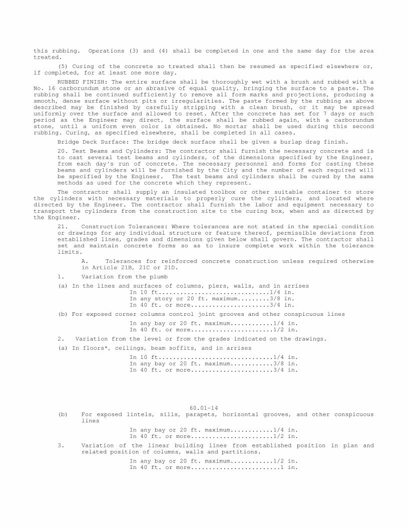
this rubbing. Operations (3) and (4) shall be completed in one and the same day for the area treated.
(5) Curing of the concrete so treated shall then be resumed as specified elsewhere or, if completed, for at least one more day.
RUBBED FINISH: The entire surface shall be thoroughly wet with a brush and rubbed with a No. 16 carborundum stone or an abrasive of equal quality, bringing the surface to a paste. The rubbing shall be continued sufficiently to remove all form marks and projections, producing a smooth, dense surface without pits or irregularities. The paste formed by the rubbing as above described may be finished by carefully stripping with a clean brush, or it may be spread uniformly over the surface and allowed to reset. After the concrete has set for 7 days or such period as the Engineer may direct, the surface shall be rubbed again, with a carborundum stone, until a uniform even color is obtained. No mortar shall be used during this second rubbing. Curing, as specified elsewhere, shall be completed in all cases.
Bridge Deck Surface: The bridge deck surface shall be given a burlap drag finish.
20. Test Beams and Cylinders: The contractor shall furnish the necessary concrete and is to cast several test beams and cylinders, of the dimensions specified by the Engineer, from each day's run of concrete. The necessary personnel and forms for casting these beams and cylinders will be furnished by the City and the number of each required will be specified by the Engineer. The test beams and cylinders shall be cured by the same methods as used for the concrete which they represent.
The contractor shall supply an insulated toolbox or other suitable container to store the cylinders with necessary materials to properly cure the cylinders, and located where directed by the Engineer. The contractor shall furnish the labor and equipment necessary to transport the cylinders from the construction site to the curing box, when and as directed by the Engineer.
21. Construction Tolerances: Where tolerances are not stated in the special condition or drawings for any individual structure or feature thereof, permissible deviations from established lines, grades and dimensions given below shall govern. The contractor shall set and maintain concrete forms so as to insure complete work within the tolerance limits.
A. Tolerances for reinforced concrete construction unless required otherwise in Article 21B, 21C or 21D.
1. Variation from the plumb
(a) In the lines and surfaces of columns, piers, walls, and in arrises In 10 ft...............................1/4 in. In any story or 20 ft. maximum.........3/8 in. In 40 ft. or more......................3/4 in.
(b) For exposed corner columns control joint grooves and other conspicuous lines
In any bay or 20 ft. maximum............1/4 in. In 40 ft. or more.......................1/2 in.
2. Variation from the level or from the grades indicated on the drawings.
(a) In floors*, ceilings, beam soffits, and in arrises
In 10 ft................................1/4 in. In any bay or 20 ft. maximum............3/8 in. In 40 ft. or more.......................3/4 in.
60.01-14 (b) For exposed lintels, sills, parapets, horizontal grooves, and other conspicuous
lines
In any bay or 20 ft. maximum............1/4 in. In 40 ft. or more.......................1/2 in.
3. Variation of the linear building lines from established position in plan and related position of columns, walls and partitions.
In any bay or 20 ft. maximum............1/2 in. In 40 ft. or more.........................1 in.
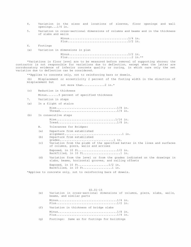
4. Variation in the sizes and locations of sleeves, floor openings and wall openings...1/4 in.
5. Variation in cross-sectional dimensions of columns and beams and in the thickness of slabs and walls
Minus...................................1/4 in. Plus....................................1/2 in.
6. Footings
(a) Variation in dimensions in plan
Minus...................................1/2 in. Plus......................................2 in.**
*Variations in floor level are to be measured before removal of supporting shores; the contractor is not responsible for variations due to deflection, except when the latter are corroboratory evidence of inferior concrete quality or curing, in which care only the net variation due to deflection can be considered.
**Applies to concrete only, not to reinforcing bars or dowels.
(b) Misplacement or eccentricity 2 percent of the footing width in the direction of misplacement but
not more than.............2 in.*
(c) Reduction in thickness
Minus.......5 percent of specified thickness
7. Variation in steps
(a) In a flight of stairs
Rise....................................1/8 in. Thread..................................1/4 in.
(b) In consecutive steps
Rise...................................1/16 in. Tread...................................1/8 in.
B. Tolerances for Bridges:
(a) Departure from established alignment..................................1 in. (b) Departure from established grades................................1 in. (c) Variation from the plumb of the specified batter in the lines and surfaces
of columns, piers, walls and arrises
Exposed, in 10 ft.......................1/2 in. Backfilled, in 10 ft......................1 in.
(d) Variation from the level or from the grades indicated on the drawings in slabs, beams, horizontal grooves, and railing offsets
Exposed, in 10 ft..................1/2 in. Backfilled, in 10 ft.................1 in.
*Applies to concrete only, not to reinforcing bars of dowels.
60.01-15 (e) Variation in cross-sectional dimensions of columns, piers, slabs, walls,
beams, and similar parts
Minus...................................1/4 in. Plus....................................1/2 in.
(f) Variation in thickness of bridge slabs
Minus...................................1/8 in. Plus....................................1/4 in.
(g) Footings: Same as for footings for buildings
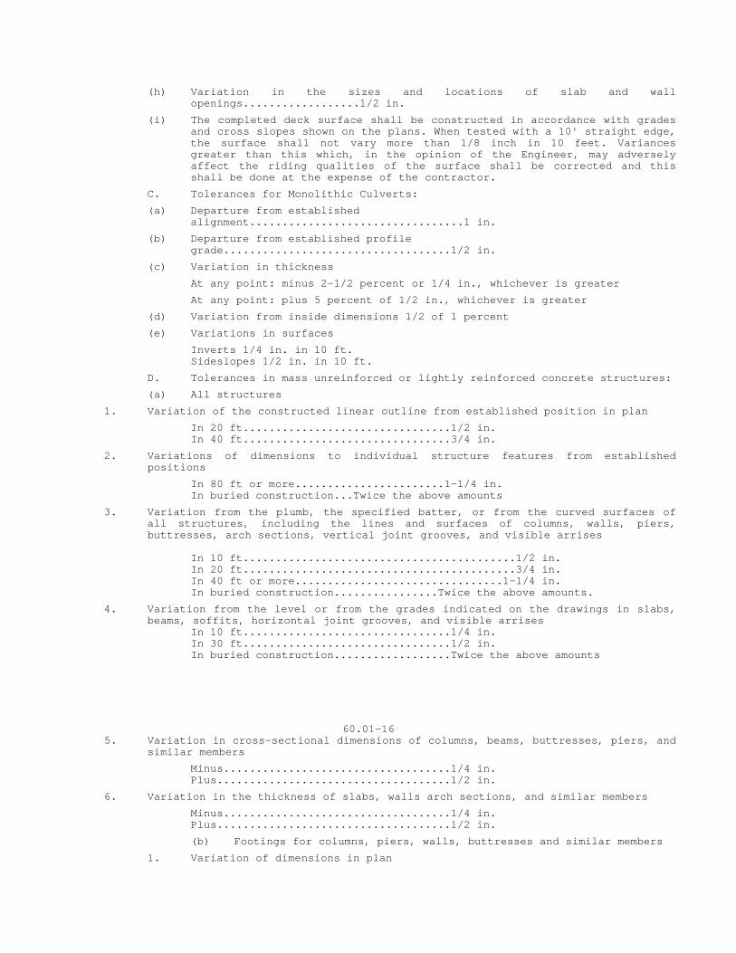
(h) Variation in the sizes and locations of slab and wall openings..................1/2 in.
(i) The completed deck surface shall be constructed in accordance with grades and cross slopes shown on the plans. When tested with a 10' straight edge, the surface shall not vary more than 1/8 inch in 10 feet. Variances greater than this which, in the opinion of the Engineer, may adversely affect the riding qualities of the surface shall be corrected and this shall be done at the expense of the contractor.
C. Tolerances for Monolithic Culverts:
(a) Departure from established alignment.................................1 in.
(b) Departure from established profile grade...................................1/2 in.
(c) Variation in thickness
At any point: minus 2-1/2 percent or 1/4 in., whichever is greater
At any point: plus 5 percent of 1/2 in., whichever is greater
(d) Variation from inside dimensions 1/2 of 1 percent
(e) Variations in surfaces
Inverts 1/4 in. in 10 ft. Sideslopes 1/2 in. in 10 ft.
D. Tolerances in mass unreinforced or lightly reinforced concrete structures:
(a) All structures
1. Variation of the constructed linear outline from established position in plan
In 20 ft................................1/2 in. In 40 ft................................3/4 in.
2. Variations of dimensions to individual structure features from established positions
In 80 ft or more.......................1-1/4 in. In buried construction...Twice the above amounts
3. Variation from the plumb, the specified batter, or from the curved surfaces of all structures, including the lines and surfaces of columns, walls, piers, buttresses, arch sections, vertical joint grooves, and visible arrises
In 10 ft..........................................1/2 in. In 20 ft..........................................3/4 in. In 40 ft or more................................1-1/4 in. In buried construction................Twice the above amounts.
4. Variation from the level or from the grades indicated on the drawings in slabs, beams, soffits, horizontal joint grooves, and visible arrises
In 10 ft................................1/4 in. In 30 ft................................1/2 in. In buried construction..................Twice the above amounts
60.01-16 5. Variation in cross-sectional dimensions of columns, beams, buttresses, piers, and
similar members
Minus...................................1/4 in. Plus....................................1/2 in.
6. Variation in the thickness of slabs, walls arch sections, and similar members
Minus...................................1/4 in. Plus....................................1/2 in.
(b) Footings for columns, piers, walls, buttresses and similar members
1. Variation of dimensions in plan
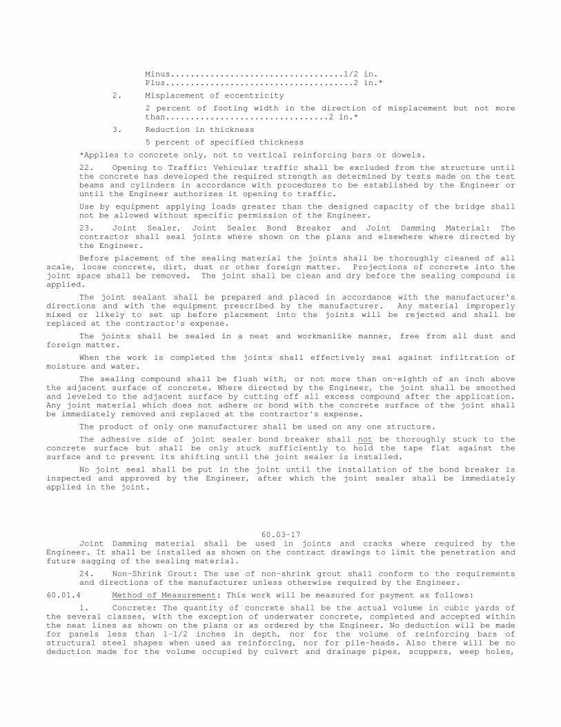
Minus...................................1/2 in. Plus......................................2 in.*
2. Misplacement of eccentricity
2 percent of footing width in the direction of misplacement but not more than.................................2 in.*
3. Reduction in thickness
5 percent of specified thickness
*Applies to concrete only, not to vertical reinforcing bars or dowels.
22. Opening to Traffic: Vehicular traffic shall be excluded from the structure until the concrete has developed the required strength as determined by tests made on the test beams and cylinders in accordance with procedures to be established by the Engineer or until the Engineer authorizes it opening to traffic.
Use by equipment applying loads greater than the designed capacity of the bridge shall not be allowed without specific permission of the Engineer.
23. Joint Sealer, Joint Sealer Bond Breaker and Joint Damming Material: The contractor shall seal joints where shown on the plans and elsewhere where directed by the Engineer.
Before placement of the sealing material the joints shall be thoroughly cleaned of all scale, loose concrete, dirt, dust or other foreign matter. Projections of concrete into the joint space shall be removed. The joint shall be clean and dry before the sealing compound is applied.
The joint sealant shall be prepared and placed in accordance with the manufacturer’s directions and with the equipment prescribed by the manufacturer. Any material improperly mixed or likely to set up before placement into the joints will be rejected and shall be replaced at the contractor's expense.
The joints shall be sealed in a neat and workmanlike manner, free from all dust and foreign matter.
When the work is completed the joints shall effectively seal against infiltration of moisture and water.
The sealing compound shall be flush with, or not more than on-eighth of an inch above the adjacent surface of concrete. Where directed by the Engineer, the joint shall be smoothed and leveled to the adjacent surface by cutting off all excess compound after the application. Any joint material which does not adhere or bond with the concrete surface of the joint shall be immediately removed and replaced at the contractor's expense.
The product of only one manufacturer shall be used on any one structure.
The adhesive side of joint sealer bond breaker shall not be thoroughly stuck to the concrete surface but shall be only stuck sufficiently to hold the tape flat against the surface and to prevent its shifting until the joint sealer is installed.
No joint seal shall be put in the joint until the installation of the bond breaker is inspected and approved by the Engineer, after which the joint sealer shall be immediately applied in the joint.
60.03-17 Joint Damming material shall be used in joints and cracks where required by the Engineer. It shall be installed as shown on the contract drawings to limit the penetration and future sagging of the sealing material.
24. Non-Shrink Grout: The use of non-shrink grout shall conform to the requirements and directions of the manufacturer unless otherwise required by the Engineer.
60.01.4 Method of Measurement: This work will be measured for payment as follows:
1. Concrete: The quantity of concrete shall be the actual volume in cubic yards of the several classes, with the exception of underwater concrete, completed and accepted within the neat lines as shown on the plans or as ordered by the Engineer. No deduction will be made for panels less than 1-1/2 inches in depth, nor for the volume of reinforcing bars of structural steel shapes when used as reinforcing, nor for pile-heads. Also there will be no deduction made for the volume occupied by culvert and drainage pipes, scuppers, weep holes,
public utility structures or any other opening, unless the surface area of any such single opening is 9 square feet or more.
In the case of culverts or drainage pipes the computation of the surface area shall be based on the nominal diameter of the pipe, disregarding the thickness of the shell.
Underwater concrete when specified will be measured by the volume in cubic yards completed and accepted within the horizontal limits of the cofferdam shown on the plans in which it is placed and between the elevations established by the Engineer. When underwater concrete is not originally specified but is required, it will be measured by the volume in cubic yards completed and accepted within the actual horizontal limits of the cofferdam in which it is placed and between the elevations established by the Engineer.
60.01.05 Basis of Payment: Payment for this work will be made as follows:
1. Concrete: The various classes of concrete will be paid for at their respective contract unit price per cubic yard, complete in place, which price shall include all materials, equipment, tools, labor and work incidental thereto.
No special payment shall be made for the use of high early strength cement when required by the plans, specifications, or the Engineer.
2. Underwater Concrete: When this class of concrete is constructed, it will be paid for at the contract unit price per cubic yard for "Underwater Concrete", complete in place, which price shall include all materials, equipment, tools, labor and work incidental thereto.
3. Ornament or Reverse Moulds: This material will be paid for at the contract lump sum price for "Ornament Moulds: complete in place, including furnishing, setting, removal and all incidental expense.
4. No Direct Payment: Unless specifically provided for elsewhere in these specifications, or the contract plans, no direct payment will be made for non-shrink grout, weephole piping, all heating, all admixtures, wettable lampblack, joint sealer, joint sealer bond breaker, joint damming material, tar paper, nor for the concrete in or curing of the required test beams and cylinders as specified hereinbefore, but the cost of this work shall be considered as included in the general cost of the work. The work of transporting and testing these beams and cylinders will be done by the City without expense to the contractor.
60.01-18
SECTION 60.02 REINFORCING STEEL
60.02.01 DESCRIPTION
This item shall consist of furnishing and placing reinforcing steel for structures, of the kind, size and quantity designated in conformity with the requirements of the plans or as ordered in accordance with these specifications.
60.02.02 MATERIALS
The materials for this work shall conform to the requirements of Article 2.11.
Only one of the specified grades of reinforcing steel shall be used in any one structure.
60.02.03 CONSTRUCTION METHODS
1. Order Lists: Before fabricating any material the contractor shall verify the material bills and bending diagrams if they are shown on the plans. When they are not shown, all material bills and bending diagrams shall be furnished by the contractor for the approval of the Engineer, and no materials shall be ordered until such material bills and bending diagrams have been approved. The approval of such by the Engineer shall in no way relieve the contractor of responsibility for the correctness of such material bills and diagrams. Any expense incident to the revision of material furnished in accordance with such material bills and diagrams to make it comply with the requirements of the plans shall be borne by the contractor.
2. Protection of Materials: Reinforcing steel shall be protected from injury and deterioration at all times. Before being placed in the work it shall be cleaned of all dirt, loose mill scale and rust, paint, oil, grease or other foreign material.
3. Fabrication: Bar reinforcement shall be cold bent to the shapes shown on the plans and unless otherwise shown on the plans or authorized by the Engineer, bends shall be made in accordance with the following requirements:
Stirrups and tie bars shall be bent around a pin having a diameter not less than twice the thickness of the bar.
Bends for other bars shall be made around a pin having a diameter not less than 6 times the minimum thickness except for bars one inch or larger, in which case the bends shall be made around a pin of 8 bar diameters.
Bar reinforcement shall be shipped in standard bundles tagged and marked in accordance with the Code of Standard Practice of the Concrete Reinforcement Steel Institute.
4. Placing and Fastening: All steel reinforcement shall be accurately placed in the position shown on the plans and firmly held during the placing and setting of concrete. Bars shall be tied or welded at all intersections except where the spacing is less than one foot in each direction when alternate intersections shall be tied or welded unless otherwise indicated on the plans.
Distances from the forms shall be maintained by means of stays, blocks, ties, hangers or other approved supports. Blocks for holding reinforcement from contact with the forms shall be precast mortar blocks of approved shape and dimensions or approved metal chairs. Metal chairs which are in contact with the exterior surface of the concrete shall be galvanized. Layers of bars shall be separated by precast mortar blocks or by other equally suitable devices. The use of pebbles, pieces of broken stone or brick, metal pipe and wooden blocks shall not be permitted. Reinforcement in any member shall be placed and then inspected and approved by the Engineer before the placing of concrete begins. Concrete placed in violation of this regulation may be rejected and its removal required.
60.02-01 If fabric reinforcement is shipped in rolls, it shall be straightened into flat sheets before being placed.
5. Splicing: All reinforcement shall be furnished in the full lengths indicated on the plans. Splicing of bars except where shown on the plans will not be permitted without the written approval of the Engineer. Splices shall be staggered insofar as possible.
Unless otherwise shown on the plans, bars in the bottom of beams and girders, and in walls, columns and haunches shall be lapped 20 diameters and bars near top of beams and girders having more than 12 inches of concrete under the bars shall be lapped 35 diameters to make the splice. In lapped splices, the bars shall be placed in contact and wired together. Welding of reinforcing steel for the purpose of splicing shall be done only if detailed on the plans or if authorized in writing by the Engineer. Welding shall conform to the requirements of Article 60.03.03-34.
6. Lapping: Sheets of mesh or bar mat reinforcement shall overlap each other sufficiently to maintain a uniform strength and shall be securely fastened at the ends and edges. The edge lap shall be not less than one mesh in width.
7. Substitutions: Substitution of different size bars will be permitted only with the specific authorization of the Engineer. If substitutions are allowed, the resulting area of reinforcement shall be equal to the area called for on the plans or larger.
60.02.04 METHOD OF MEASUREMENT
The amount of reinforcing steel to be paid for shall be the number of pounds or square yards of reinforcement actually placed as shown on the plans or as order by the Engineer. The weight paid for shall be the computed weight of the reinforcement placed.
The unit weights used for computing the weight of reinforcing bars shall be as indicated in the tables of Article 2.11.01.
No payment will be made for any fastening devices that may be used for keeping the reinforcement in correct position. In case the Engineer allows the substitution of larger bars than have been specified, payment will be made only for the amount of metal that would have been required if the specified size of bars had been used, unless the Engineer shall have submitted an alternate steel schedule in which case the steel will be paid for in accordance with the actual amount placed. In case short bars are used when full length bars might reasonably be required, the weight paid for shall be only that which would be obtained if full length bars were used, no allowance being made for laps not contemplated by the plans unless allowed by the Engineer.
60.02.05 BASIS OF PAYMENT
Reinforcing steel will be paid for at the contract unit price per pound for "Deformed Steel Bars" and per square yard for "Wire Mesh", complete in place, including furnishing, fabrication and placing and all materials, equipment, tools, labor and work incidental thereto. The contract unit price per pound for "Deformed Steel Bars" shall also include all costs incidental to the preparation and furnishing of material bills, placement diagrams and bending diagrams when these details are not shown on the plans.
In the case of structures of reinforced concrete where there are no structural steel bid items, such minor metal parts as expansion joints, bolts, and the like shall, unless otherwise specified, be paid for at the contract unit price for bar reinforcement.

60.02-2
SECTION 60.03 STRUCTURAL STEEL
60.03.01 DESCRIPTION
This item shall consist of furnishing, fabricating, transporting, erecting and painting structural steel, rivet and eyebar steel, steel forgings, wrought iron, steel castings, gray iron castings, malleable castings and phosphor bronze of the kind, size and quantity designated, in conformity with the requirements of the plans or as ordered and in accordance with these specifications.
60.03.02 MATERIALS
The materials for this work shall conform to the requirements of Article 2.11.02 and Section 2.12.
60.03.03 CONSTRUCTION METHODS
1. Workmanship and Finish: The workmanship and finish shall be equal to the best general practice in modern shops.
2. Storage of Materials: Structural material, either plain or fabricated, shall be stored at the shop above the ground upon platforms skids or other supports. It shall be kept free from dirt, grease and other foreign matter and shall be protected, as far as practicable, from corrosion.
3. Straightening Materials: Rolled material must be straight before being laid out or worked. If straightening is necessary, it shall be done by methods that will not injure the material. Sharp kinks and bends shall be cause for rejection of the material.
4. Finish: Portions of the work exposed to view shall be finished neatly. Shearing, chipping and flame cutting shall be done carefully and accurately.
5. Rivet Holes: All holes for rivets shall be either punched or drilled. Material forming parts of a member composed of not more than five thicknesses of metal may be punched 1/16 inch larger than the nominal diameter of the rivets whenever the thickness of the metal is not greater than 3/4 inch for carbon steel or 5/8 inch for alloy steel. When there are more than five thicknesses or when any of the main material is thicker than 3/4 inch for carbon steel or 5/8 inch for alloy steel, or when required under Article 60.03.03-8 all holes shall be sub-punched or sub-drilled 3/16 inch smaller and, after assembling, reamed 1/16 inch larger, or drilled from the solid 1/16 inch larger than the nominal diameter of the rivets.
6. Punched Holes: The diameter of the die shall not exceed the diameter of the punch by more than 1/16 inch. If any holes must be enlarged to admit rivets, they shall be reamed. Holes shall be clean cut, without torn or ragged edges. Poor matching of holes will be cause for rejection.
7. Reamed or Drilled Holes: Reamed holes shall be cylindrical, perpendicular to the member and not more than 1/16 inch larger than the nominal diameter of the rivets. When practicable, reamers shall be directed by mechanical means. Drilled holes shall be 1/16 inch larger than the nominal diameter of the rivets. Burrs on the outside surfaces shall be removed. Poor matching of holes will be cause for rejection. Reaming and drilling shall be done with twist drills. If required by the Engineer, assembled parts shall be taken apart for removal of burrs caused by drilling. Connecting parts requiring reamed or drilled holes, shall be assembled and securely held while being reamed or drilled and shall be match-marked before disassembling.
8. Sub-punching, Reaming and Shop Assembly: Unless otherwise specified, holes in all field connections and field splices of main truss or arch members, continuous beams, plate girders and rigid frames shall be sub-punched, or sub-drilled if sub-drilling is required according to Article 60.03.03-5 and reamed while assembled in the shop. The assembly, including camber, alignment, accuracy of holes and milled joints shall be approved by the Engineer before reaming is commenced.
60.03-1
Unless otherwise authorized by the Engineer, each individual full-length truss, arch, continuous beam or girder shall be assembled in the shop before reaming is commenced.
All holes for floor beam and stringer field end connections shall be sub-punched and reamed to a steel template or reamed while assembled.
If additional sub-punching or reaming is required; it shall be specified in the special provisions or on the plans.
9. Accuracy of Punched Holes: All holes punched full size, or sub-punched, shall be so accurately punched that after assembling and before any reaming is done, a cylindrical pin 1/8 inch smaller in diameter than the nominal size of the punched hole may be entered perpendicular to the face of the member, without drifting, in at least 75 percent of the contiguous holes in the same plane. If the requirement is not fulfilled, the badly punched piece will be rejected. If any hole will not pass a pin 3/16 inch smaller in diameter than the nominal size of the punched hole, this will be cause for rejection.
10. Accuracy of Sub-drilled Holes: The accuracy of sub-drilled holes shall be the same as required for punched holes.
11. Accuracy of Reamed and Drilled Holes: When holes are reamed or drilled, 85 percent of the holes in any contiguous group shall, after reaming or drilling, show no offset greater than 1/32 inch between adjacent thicknesses of metal.
12. Shop Assembling: Shop assembly of trussed, arches, continuous beam spans rigid frames and plate girders shall be according to Article 60.03.03-8.
Complete shop assembly of an entire structure, including floor system which may be necessary in the case of complicated designs of skewed and superelevated structures, shall be done only if required by the special provisions.
Surfaces of metal in contact shall be cleaned before assembling. The parts of a member shall be assembled, well pinned and firmly drawn together with bolts before reaming or riveting is commenced. Assembled pieces shall be taken apart, if necessary, for the removal of burrs and shavings, produced by the reaming operation. The member shall be free from twists, bends and other deformation.
Preparatory to the shop riveting of full size punched material, the rivet holes, if necessary, shall be spear-reamed for the admission of the rivets. The reamed holes shall not be more than 1/16 inch larger than the nominal diameter of the rivets.
End connection angles, stiffener angles and similar parts shall be carefully adjusted to correct position and bolted, clamped or otherwise firmly held in place until riveted.
Parts not completely riveted in the shop shall be secured by bolts, insofar as practicable, to prevent damage in shipment and handling.
13. Drifting of Holes: The drifting done during assembling shall be only such as to bring the parts into position, and not sufficient to enlarge the holes or distort the metal. If any holes must be enlarged to admit the rivets, they shall be reamed.
14. Match-marking: Connecting parts assembled in the shop for the purpose of reaming or drilling holes in field connections shall be match-marked, and a diagram showing such marks shall be furnished to the Engineer.
15. Rivets: The size of rivets indicated upon the plans shall be understood to mean their size before heating.
Rivet heads shall be of standard shape, unless otherwise specified, and of uniform size for the same diameter of rivet. They shall be full, neatly formed, concentric with the rivet holes, and in full contact with the surface of the member.
16. Field Rivets: Sufficient field rivets shall be furnished to rivet the entire structure, with an ample surplus to replace all rivets burned, cut out or lost.
17. Bolts and Bolted Connections:
(a) General: Bolted connections shall not be used unless shown on the plans. Where bolted connections are permitted, the bolts furnished shall be unfinished, ordinary rough or machine bolts. Turned bolts shall be provided if shown on the plans or required by the special provisions. Special ribbed drive fit bolts may be substituted for turned bolts upon written approval of the Engineer.
60.03-02
The holes shall be truly cylindrical. The size of holes shall be 1/16 inch greater than the nominal bolts diameter and shall make a driving fit with the bolts. Holes shall be at right angles to the surface of the metal so that both head and nut will bear squarely against the metal. Bolts shall be driven accurately into the holes without damaging the thread. A snap shall be used to prevent damaging the heads.
The heads and nuts shall be drawn tightly against the work with a suitable wrench not less than 15 inches long. Bolt heads shall be tapped with a hammer while the nut is being tightened. When bolts are to be used in beveled surfaces, beveled washers shall be provided to give full bearing to the head or nut. Ribbed bolts shall be furnished in the same numbers and in nominal sizes not smaller than the rivets for which they are substituted. They shall be furnished in sufficient variety of lengths that when drawn tight the fluted shanks will fill the holes in the work and the thread will completely fill the nut with not more than one thread protruding. All bolts shall have cut threads, neatly and accurately finished.
If, for any reason, the bolts twist before drawing tight, the hole shall be carefully reamed and the bolt replaced with a new bolt of diameter to fit properly in the hole.
The contractor shall provide and supply himself with oversize bolts for this replacement in an amount not less than 10 per cent of the number of ribbed bolts specified.
The nuts of unfinished bolts, turned bolts and ribbed bolts shall be effectively locked after they have been finally tightened.
(b) Unfinished Bolts: Unfinished bolts shall be standard bolts with hexagonal heads and nuts. The diameter of the bolt holes shall be 1/16 inch greater than the diameter of the bolts used. Bolts transmitting shear shall be threaded to such a length that not more than one thread will be within the grip of the metal. The bolts shall be of such length that they will extend entirely through their nuts, but not more than 1/4 inch beyond them. The number of bolts furnished shall be 5 per cent more than the actual number shown on the plans for each size and length.
(c) Turned Bolts: Holes for turned bolts shall be carefully reamed and the bolts turned to a driving fit with the threads entirely outside of the holes and a washer shall be used. The heads and nuts shall be hexagonal.
One-fourth inch nut locks shall be used on all turned bolts unless otherwise specified on the plans. Turned bolts shall be finished by a finishing cut.
(d) Special Ribbed Bolts: Ribbed bolts, with drive fit shall be used only where called for on the plans. Ribbed bolts may be substituted for field rivets in locations where, in the opinion of the Engineer, it is impracticable to drive rivets.
(e) High-Tensile-Strength Bolts: When specified on the plans, high tensile-strength bolts may be substituted for rivets for field connections at the option of the contractor. The requirements and methods set forth in the current edition of Standard Specifications for Highway Bridges adopted by A.A.S.H.O., or other standards specified in the special conditions, for the installation of High-tensile-strength bolts, shall govern. Where alternate methods of installation are specified, only one method shall be used on any one structure.
18. Riveting: Rivets shall be heated uniformly to a light "cherry red" color and shall be driven while hot. Any rivet whose point is heated more than the remainder shall not be driven. When a rivet is ready for driving, it shall be free from slag, scale and other adhering matter. Any rivet which, in the opinion of the Engineer, is scaled excessively, will be rejected.
All rivets that are loose burned, badly formed or otherwise defective shall be removed and replaced with satisfactory rivets. Any rivet whose head is deficient in size or whose head is driven off center will be considered defective and shall be removed. Stitch rivets that are loosened by the driving of adjacent rivets shall be removed and replaced with satisfactory rivets. Caulking, recupping or double gunning or rivet heads will not be permitted.
Shop driven rivets shall be driven by direct-acting rivet machines when practicable. Approved beveled rivet sets shall be used for forming rivet heads on sloping surfaces. When the use of a direct acting rivet machine is not practicable, pneumatic hammers of approved size shall be used. Pneumatic bucking tools will be required when, in the opinion of the Engineer, the size and length of the rivets warrant their use.
60.03-03
Rivets may be driven cold provided their diameter is not over 3/8 inch. Rivets shall be of the same grade as used for hot riveting, except that hot-made rivets shall not be quenched and cold-made rivets shall be annealed.
19. Edge Planing: Sheared edges of plates more than 5/8 inch in thickness and carrying calculated stress shall be planed to depth of 1/4 inch. Reentrant cuts shall be filleted before cutting.
20. Flame Cutting: Steel or wrought iron may be flame cut providing a smooth surface is secured by the use of a mechanical guide. Flame cutting by hand shall be done only where approved by the Engineer and the surface shall be made smooth by planing, chipping or grinding. The cutting flame shall be so adjusted and manipulated as to avoid cutting beyond the prescribed lines. Reentrant cuts shall be filleted.
In the case of silicon steel, flame cut edges shall be removed to a depth of at least 1/4 inch by milling, chipping or grinding, except that machine flame-cut edges may be used without such removal if the edges are softened after cutting:
(a) By heating the cut edge uniformly and progressively to a red heat, visible in ordinary shop light (1,150 to 1,250 degree F.) to a depth of a least 1/16 inch; or (b) by means of a post heating torch attached to and following the cutting torch; the tips, gas pressure, speed of travel and the distance of post heating torch from kerf regulated to the thickness of the steel. Bend test specimens so cut and flame softened shall meet the bend test requirements for that thickness in A.S.T.M. A-94.
21. Facing of Bearing Surfaces: The top and bottom surfaces of steel slabs and base plates and cap plates of columns and pedestals shall be planed, or else the plates or slabs shall be hot straightened. Parts of members in contact with them shall be faced.
Sole plates of beams and girders shall have full contact with the flanges. Sole plates and masonry plates shall be planed or hot straightened. Cast pedestals shall be planed on surfaces to be in contact with steel and shall have the surfaces to be in contact with masonry rough finished.
Surfaces of bronze bearing plates intended for sliding contact shall be finished.
In planing surfaces of expansion bearings the cut of the tool shall be in the direction of expansion.
22. Abutting Joints: Abutting joints in compression members and girder flanges and in tension members where so specified on the plans, shall be faced and brought to an even bearing. When joints are not faced, the opening shall not exceed 1/4 inch.
23. End Connection Angles: Floor beams, stringers, and girders having end connection angles shall be built to exact length back to back of connection angles. If end connection angles are faced, the finished thickness of the angles shall not be less than that shown on the detail drawings.
24. Lacing Bars: The ends of lacing bars shall be neatly rounded unless another form is required.
25. Finished Members: Finished members shall be true to line and free from twists, bends and open joints.
26. Web Plates: In girders having no cover plates and not to be encased in concrete, the top edge of the web plate shall not extend above the backs of the flange angles and shall not be more than 1/8 inch below at any point. Any portion of the plate projecting beyond the angles shall be chipped flush with the backs of the angles. Web plates of girders having cover plates may be 1/2 inch less in width than the distance back-to-back of flange angles.
Splices in webs of girders without cover plates shall be sealed on the top by welding. At web splices, the clearance between ends of the web plates shall not exceed 3/8 inch. The clearance at the top and bottom ends of the web splice plates shall not exceed 1/4 inch.
27. Bent Plates: Cold-bent load carrying rolled steel plates shall conform to the following:
(1) They shall be so taken from the stock plates that the direction of bending will be at right angles to the direction of rolling.
60.03-04
(2) The radius of bends, measured to the concave face of the metal, shall not be less and preferably shall be greater than shown in the following table in which "T" is the thickness of the plate:
Angle through which plate is bent Minimum Radius
61 degrees to 90 degrees 1.0T 91 degrees to 120 degrees 1.5T 121 degrees to 150 degrees 2.0T
(3) Before bending, the corners of the plates shall be rounded to a radius of 1/6 inch throughout that portion of the plate at which the bending is to occur. If a shorter radius is essential, the plates shall be bent hot. Hot-bent plates shall conform to requirement (1) above.
28. Fit of Stiffeners: End stiffener angles of girders and stiffener angles intended as supports for concentrated loads shall be milled or ground to secure an even bearing against the flange angles. Intermediate stiffener angles shall fit sufficiently tight to exclude water after being painted. Fillers under stiffeners shall fit within 1/4 inch at each end.
Welding will be permitted in lieu of milling or grinding if noted on the plans or specified in the special provisions. Welding transversely across the tension flanges of beams or girders, which have a flange stress of more than 75 per cent of their designed capacity, will not be permitted.
29. Eyebars: Eyebars shall be straight, true to size, and free from twists, folds in the neck or head, and other defects. Heads shall be made by upsetting and rolling or forging and not by welding. The form of the heads will be determined by the dies in use at the works where the eyebars are made, if they are satisfactory to the Engineer. The thickness of head ad neck shall not over run more than 1/16 inch.
Eyebars that are to be placed side by side in the structure shall be bored so accurately that, upon being placed together, pins 1/32 inch less in diameter than the pin holes will pass through the holes at both ends at the same time without driving.
30. Annealing: Before boring, eyebars shall be annealed to produce the required physical qualities and shall be straightened. Proper instruments shall be provided for determining the temperature of the bars at any time.
Other steel that has been heated partially shall be annealed, unless it is to be used in minor parts. Crimped stiffeners need not be annealed.
31. Pins and Rollers: Pins and rollers shall be accurately turned to the dimensions shown on the plans and shall be smooth, straight, and free from flaws.
Pins and rollers more than 7 inches in diameter shall be forged and annealed.
In pins larger than 9 inches in diameter, a hole not less than 2 inches in diameter shall be bored full length along the axis after the forging has been allowed to cool to a temperature below the critical range under suitable conditions to prevent injury by too rapid cooling and before being annealed.
32. Boring Pinholes: Pinholes shall be bored true to the specified diameter, smooth and straight, at right angles with the axis of the member and parallel with each other unless otherwise required. The final surface shall be produced by finishing cut. The distance outside-to-outside of holes in tension members and inside-to-inside of holes in compression members shall not vary from that specified more than 1/32 inch. Boring of holes in built up members shall be done after the riveting is completed.
33. Pin Clearances: The diameter of the pin hole shall not exceed that of the pin by more than 1/50” for pins 5 inches or less in diameter, or 1/32” for larger pins.
34. Welding: Welding of steel structures or parts thereof, when authorized or required by the provisions of the plans, specifications or special provisions, shall conform to the requirements of the Specifications for Welded Highway and Railroad Bridges of the American Welding Society, unless specified otherwise in the "Special Conditions", as supplemented and revised by the following clauses:
60.03-05
(a) Qualification of Operators: No welding operator shall be permitted to work on the project, either in the shop or in the field, who has not been properly qualified in accordance with the requirements of the above referred to specifications. The qualification testing shall be carried out under the supervision of the Engineer except that, at his discretion, he may approve qualification under other supervision satisfactory to him.
If a welding operator on any project has not been engaged in welding operations on a City project, or a project acceptable to the City for a period of 12 months or more, or if he cannot produce a suitable approved welding certificate dated not more than 12 months previously from a welding agency acceptable to the Engineer, he shall be required to requalify through examination.
The City will furnish the metal with which the sample weld specimens, or coupons, shall be made, except for the spiral shear connector loops and the steel plate or shape for the welding test for spiral shear connectors. The contractor shall furnish without cost to the City all welding equipment, appurtenances necessary to perform the test welding, protective equipment, filler metal, and when the test is for spiral shear connectors, a spiral consisting of at least two loops together with a section of steel plate or shape of suitable length and thickness for the test welding.
Unless otherwise instructed by the Engineer, the welder taking the examination shall weld one sample, or coupon, of 2 plates in the position that he, himself, shall specify. When the welder elects to weld a coupon in a flat position he will be certified for the flat position only if the coupon passes the required tests. When the welder elects to weld a coupon in a vertical position, he will be certified for the flat and vertical positions if the coupon passes the required tests. When the welder elects to weld a coupon in an overhead position, he will be certified for flat, vertical and overhead positions if the coupon passes the required tests. When the welder elects to weld a spiral shear connector to a steel plate or shape, he will be certified for both the flat position and the spiral shear connector, if the specimen passes the required tests. The welder may elect to be tested for a position other than the preceding, and he will be certified for that position if the specimen passes the required tests.
The welder shall perform the welding test under the supervision of the Engineer or his designated representative who will identify the welded specimen and forward it to the Laboratory for the destructive tests deemed appropriate.
When the coupons or welded specimens pass all the required tests, the welder will be issued a dated certificate of qualifications specifying the weld position and type of weld for which the welder has been certified and he shall perform only those operations for which he is certified. If the coupons or welded specimens fail to pass any or all of the required tests, the welder will be so notified and he may apply for re-examination at any time without prejudice.
The Engineer shall require requalification in the case of those welders whose quality of work he has specific reason to question.
(b) Weather Condition: Welding, either in the shop or field will not be permitted when the air temperature is below 35 degrees F. except with the special permission of the Engineer, and in no case will welding be permitted when the air temperature is below 25 degrees F.; or when surfaces to be welded are wet from condensation, rain, snow or ice; when rain or snow is falling on the surfaces to be welded; or during periods of high wind unless the welding operator and the work are properly protected. At temperatures between 45 degrees and the lowest temperature at which welding is permitted, the surfaced within 4 inches of the point where the weld is to be started shall be heated with a gas torch to a temperature warm to the hand, or about 100 degrees F., before the weld is started and this temperature shall be maintained as a minimum about the weld area until the bead is completed.
(c) Welding Method: All welding shall be done by the submerged arc welding process except that where use of this method is not practicable the shielded metal arc process shall be used.
(d) Requirements for Preheat, Interpass Temperature: The minimum requirements for preheat, interpass temperature tabulated hereinafter shall apply, except where the requirements of Article 60.03.03-34(b) shall take precedence.
60.03-06
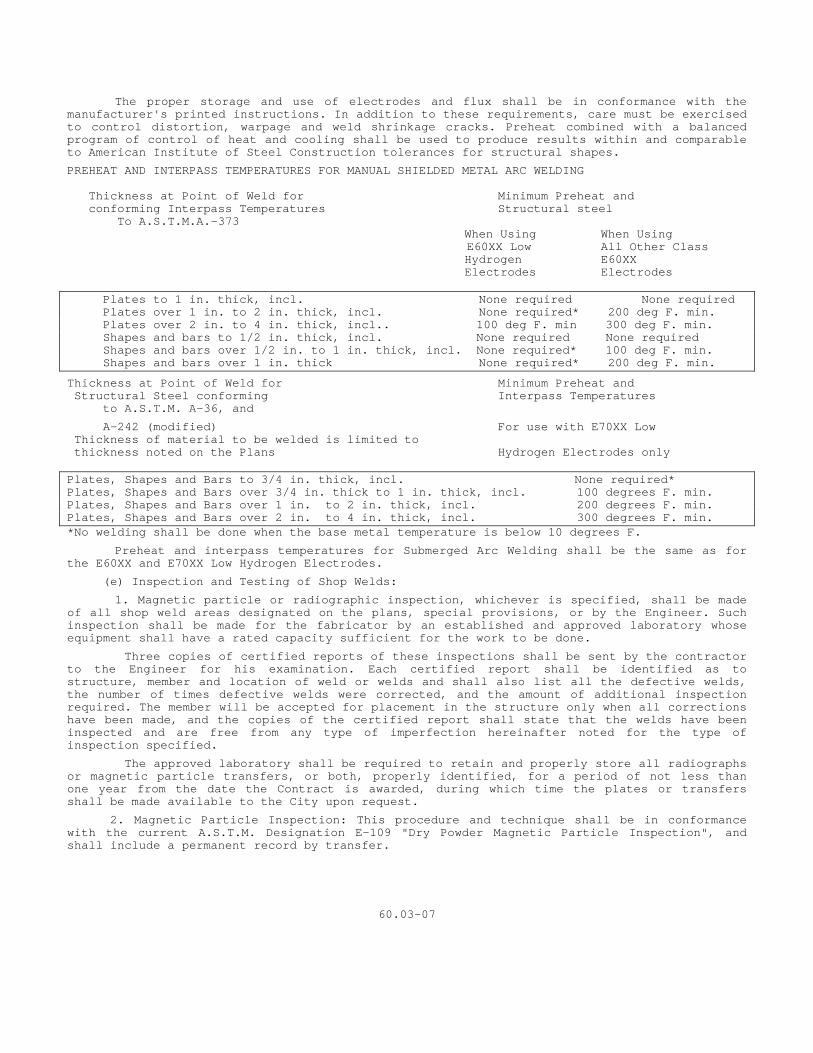
The proper storage and use of electrodes and flux shall be in conformance with the manufacturer's printed instructions. In addition to these requirements, care must be exercised to control distortion, warpage and weld shrinkage cracks. Preheat combined with a balanced program of control of heat and cooling shall be used to produce results within and comparable to American Institute of Steel Construction tolerances for structural shapes.
PREHEAT AND INTERPASS TEMPERATURES FOR MANUAL SHIELDED METAL ARC WELDING Thickness at Point of Weld for Minimum Preheat and conforming Interpass Temperatures Structural steel To A.S.T.M.A.-373
When Using When Using E60XX Low All Other Class
Hydrogen E60XX Electrodes Electrodes Plates to 1 in. thick, incl. None required None required Plates over 1 in. to 2 in. thick, incl. None required* 200 deg F. min. Plates over 2 in. to 4 in. thick, incl.. 100 deg F. min 300 deg F. min. Shapes and bars to 1/2 in. thick, incl. None required None required Shapes and bars over 1/2 in. to 1 in. thick, incl. None required* 100 deg F. min. Shapes and bars over 1 in. thick None required* 200 deg F. min.
Thickness at Point of Weld for Minimum Preheat and Structural Steel conforming Interpass Temperatures to A.S.T.M. A-36, and
A-242 (modified) For use with E70XX Low Thickness of material to be welded is limited to thickness noted on the Plans Hydrogen Electrodes only Plates, Shapes and Bars to 3/4 in. thick, incl. None required* Plates, Shapes and Bars over 3/4 in. thick to 1 in. thick, incl. 100 degrees F. min. Plates, Shapes and Bars over 1 in. to 2 in. thick, incl. 200 degrees F. min. Plates, Shapes and Bars over 2 in. to 4 in. thick, incl. 300 degrees F. min. *No welding shall be done when the base metal temperature is below 10 degrees F.
Preheat and interpass temperatures for Submerged Arc Welding shall be the same as for the E60XX and E70XX Low Hydrogen Electrodes.
(e) Inspection and Testing of Shop Welds:
1. Magnetic particle or radiographic inspection, whichever is specified, shall be made of all shop weld areas designated on the plans, special provisions, or by the Engineer. Such inspection shall be made for the fabricator by an established and approved laboratory whose equipment shall have a rated capacity sufficient for the work to be done.
Three copies of certified reports of these inspections shall be sent by the contractor to the Engineer for his examination. Each certified report shall be identified as to structure, member and location of weld or welds and shall also list all the defective welds, the number of times defective welds were corrected, and the amount of additional inspection required. The member will be accepted for placement in the structure only when all corrections have been made, and the copies of the certified report shall state that the welds have been inspected and are free from any type of imperfection hereinafter noted for the type of inspection specified.
The approved laboratory shall be required to retain and properly store all radiographs or magnetic particle transfers, or both, properly identified, for a period of not less than one year from the date the Contract is awarded, during which time the plates or transfers shall be made available to the City upon request.
2. Magnetic Particle Inspection: This procedure and technique shall be in conformance with the current A.S.T.M. Designation E-109 "Dry Powder Magnetic Particle Inspection", and shall include a permanent record by transfer.
60.03-07
Sections of weld which contain any of the below listed imperfections and are judged unacceptable by the laboratory performing such inspection shall be removed and rewelded by the fabricator and reinspected by the approved laboratory to the satisfaction of the Engineer.
A. Any type of crack or zone of incomplete fusion of penetration.
B. Any elongated slag exclusion which has a length greater than: 1/4" for T up to 3/4" 1/3 T for T from 3/4" to 2-1/4" 3/4" for T over 2-1/4"
Where T is the thickness of the thinner plate to be welded. C. Any group of slag inclusion in line that have an aggregate length greater than T in a length of 12T, except when the distance between the successive imperfections exceed 6L where L is the length of the longest imperfection in the group.
Radiographic Inspection: This procedure, techniques and standards of acceptance shall be in conformance with the current American Society of Mechanical Engineers Boiler and Pressure Vessel Code, Section VIII, Paragraph UW-51.
Sections of weld that are shown by radiography to have any type of imperfections as outlined in the above-stated Code and are judged unacceptable by the laboratory performing such inspection shall be removed and rewelded by the fabricator and radiographed again by the approved laboratory, all in accordance with the Code.
Inspection of Weld Areas not designated in the Contract: The Engineer shall have the right to require radiographic inspection or magnetic particle inspection of shop weld areas not designated in the contract. In such cases, if the inspection shows the shop weld to be defective, the cost to such inspection shall be borne by the contractor, but if the inspection shows the weld to be satisfactory, the contractor will be paid by the City for the actual cost of the inspection.
5. Qualification of Inspection Personnel: The fabricator shall furnish satisfactory proof that the personnel performing the inspection are fully qualified to do so and shall perform their work in accordance with good practice and all safety regulations.
6. Cost of Inspection: Except as stated hereinabove, there will be no direct payment made for any work required in connection with the inspection of shop welds, but the cost thereof shall be included in the contract unit price for "Structural Steel."
(f) Inspection and Testing of Field Welds: The City will make either magnetic particle inspection or radiographic inspection of field welds when so required by the plans, special provisions, or the Engineer.
The acceptability of welds will be judged in accordance with subsection (e), proceeding, for the type of inspection employed. Welds, or sections of welds, containing imperfections and judged unacceptable by the City shall be removed and rewelded by the contractor at his expense. Welds so removed and replaced will be reinspected by the Department by the same method of inspection and judged by the same criterion. All costs for the reinspection of defective welds shall be at the expense of the contractor, and these costs will be deducted from any monies due or which may become due to the contractor.
The Engineer will schedule the inspection and testing of field welds so as to keep the number of inspection trips to a feasible minimum and the contractor shall plan and prosecute the work so that this inspection may be performed in an orderly and efficient manner.
The contractor shall provide, at his expense, suitable scaffolding platforms or other means of accessibility to the area where the testing is required.
35. Screw Threads: Threads for all bolts and pins for structural steel construction shall conform to the American National Coarse Thread Series, Class 2, free fit except that for pin ends having diameters of 1 3/8 inches or more, they shall be made with six threads to the inch.
36. Pilot and Driving Nuts: Two pilot nuts and two driving nuts shall be furnished for each size of pin, unless otherwise specified.
60.03-08
ERECTION
37. General: The Contractor shall erect the structural steel, remove the temporary construction, and do all work required to complete the construction included in the contract in accordance with the plans, and specifications.
38. Plans: The contractor shall submit erection plans, prepared by the fabricator, showing a method and procedure of erection compatible with the details of fabrication.
39. Plant: The contractor shall provide the falsework and all tools, machinery and appliances, including drift pins and fitting up bolts necessary for the expeditious handling of the work.
40. Delivery of Materials: The contractor shall make all arrangements necessary to unload, handle and store all material and shall unload promptly upon delivery any material which he is required to unload. He shall be responsible for the payment of all demurrage charges.
41. Handling and Storage: Material to be stored shall be placed on skids above the ground. It shall be kept clean and properly drained. Girders and beams shall be placed upright and shored. Long members, such as columns and chords, shall be supported on skids placed near enough together to prevent injury from deflection. If the contract is for erection only, the contractor shall check the material turned over to him against the shopping lists and shall report promptly in writing any shortage or injury discovered. The Contractor shall be held responsible for any loss of material or for any damage to it, while in his care, occurring prior to its acceptance by the Engineer.
42. Straightening Bent Material: The straightening of plates, angles and other shapes shall be done by methods not likely to produce fracture or other injury. The metal shall not be heated unless permitted by the Engineer, in which case the heating shall not be to a higher temperature than that producing a dark "cherry red” color. After heating, the metal shall be cooled as slowly as possible.
Following the straightening of a bend or buckle, the surface of the metal shall be carefully inspected for evidence of fracture.
43. Assembling Steel: The parts shall be accurately assembled as shown on the plans and any matchmarks shall be followed. The material shall be carefully handled so that no parts will be bent, broken or otherwise damaged.
Hammering which will injure or distort the members shall not be done. Bearing surfaces and surfaces to be in permanent contact shall be cleaned, before the members are assembled. Unless erected by the cantilever method, truss spans shall be erected on blocking, so placed as to give the proper camber. The blocking shall be left in place until the tension chord splices are fully riveted and all other truss connections pinned and bolted. Rivets in splices of butt joints of compression members and rivets in railings shall not be driven until the span has been swung.
Splices and field connections shall have one-half of the holes filled with bolts and cylindrical erection pins (half bolts and half pins) before riveting. Splices and connections carrying traffic during erection shall have three-fourths of the holes so filled.
Fitting-up bolts shall be of the same nominal diameter as the rivets, and cylindrical erection pins shall be 1/32 inch larger.
44. Riveting: Pneumatic hammers shall be used for field riveting, except when the use of hand tools is permitted by the Engineer. Rivets larger than 7/8 inch in diameter shall not be driven by hand. Cupfaced dollies, fitting the head closely to insure good bearing, shall be used. Connections shall be accurately and securely fitted up before the rivets are driven. Drifting shall be only such as to draw the parts into position and not sufficient to enlarge the holes or distort the metal.
Unfair holes shall be reamed or drilled. Rivets shall be heated uniformly to a light "cherry red" color and shall be driven while hot. They shall not be overheated or burned. Rivet heads shall be full and symmetrical, concentric with the shank and shall have full bearing all around. They shall not be smaller than the heads of the shop rivets. Rivets shall be tight and shall grip the connected parts securely together. Caulking or recupping will not be permitted. In removing rivets, the surrounding metal shall not be injured; if necessary, they shall be drilled out.
60.03-09
45. Bolted Connections: In bolted connections, the nut shall be drawn up tight and set by center punching the threads of the bolt at the face of the nut.
46. Pin Connections: Pilot and driving nuts shall be used in driving pins. They shall be furnished by the contractor without charge. Pins shall be so driven that the members will take full bearing on them. Pin nuts shall be screwed up tight and the threads burred at the face of the nut with a pointed tool.
47. Misfits: The correction of minor misfits involving harmless amounts of reaming, cutting and chipping will be considered a legitimate part of the erection. However, any error in the shop fabrication or deformation resulting from handling and transportation which prevents the proper assembling and fitting up of parts by the moderate use of drift pins or by a moderate amount of reaming and slight chipping or cutting, shall be reported immediately to the inspector and his approval of the method of correction obtained. If the contract for complete fabrication and erection, the contractor shall be responsible for all misfits, errors and injuries and shall make the necessary corrections and replacements.
If the contract is for erection only, the inspector, with the cooperation of the contractor, shall keep a correct record of labor and materials used and the contractor shall render, within 30 days, an itemized bill for the approval of the Engineer.
PAINTING
48. General: The painting of metal structures shall include, unless otherwise provided in the contract, the preparation of the metal surfaces, the application, protection and drying of the paint coatings, and the supplying of all tools, tackle, scaffolding, labor, and materials necessary for the entire work.
49. Paint: The paint used shall conform to the requirements as stated herein and shall be as specified on the plans or in the special provisions.
50. Number of Coats and Color: Unless otherwise specified, all metal shall be painted with one shop and three field coats as follows:
(a) The shop coat and the first field coat shall be red lead ready-mixed paint conforming to the requirements of Article 2.12.04.
(b) The second and third field costs shall consist of one of the paints specified herein; the color shall be as determined by the Engineer. The coats shall be sufficiently different in color to permit detection of incomplete application.
51. Mixing of Paint: Paint shall be factory mixed except as provided herein. All paint shall also be thoroughly field mixed before applying in order to keep the pigments in uniform suspension.
52. Weather Conditions: Paint shall not be applied when the air temperature is below 40 degrees F. or when the air is misty, or when, in the opinion of the Engineer, conditions are otherwise unsatisfactory for the work. It shall not be applied upon damp or frosted surfaces.
Material painted under cover in damp or cold weather shall remain under cover until dry or until weather conditions permit its exposure in the open. Painting shall not be done when the metal is hot enough to cause the paint to blister and produce a porous paint film.
53. Application: Painting shall be done in a neat and workmanlike manner. Paint shall be applied with hand brushes, except as hereinafter provided for shop painting and inaccessible surfaces. By whatever method applied, the coating of paint shall be smoothly and uniformly spread so that no excess paint will collect at any point.
(a) Brushing: The paint shall be so manipulated under the brush as to produce a smooth, uniform, even coating in close contact with the metal or with previously applied paint, and shall be worked into all corners and crevices.
(b) Inaccessible Surfaces: On all surfaces, which are inaccessible for paint brushes, the paint shall be applied by spraying as hereinafter described or with sheepskin daubers to insure thorough covering.
60.03-10 (c) Spraying: Power spraying equipment shall apply the paint so as to secure uniform coverage in a fine even spray without the addition of any thinner. In cool weather, the paint may be warmed by approved methods to reduce viscosity for use.
54. Removal of Paint: If the painting is unsatisfactory to the Engineer, the paint shall be removed and the metal thoroughly cleaned and repainted.
55. Thinning Paint: Paint as delivered in containers is ready for use when thoroughly mixed. If it is necessary in cool weather to thin the paint, in order that it shall spread more freely, this shall be done only by approved methods.
56. Painting Galvanized Surfaces: Galvanized surfaces which are required to be painted shall be treated as follows:
For the purpose of conditioning, the painting of galvanized surfaces shall be deferred as long as possible in order that the surfaces may weather.
Before painting galvanized surfaces, they shall be treated as follows:
In one gallon of soft water dissolve 2 ounces each of copper chloride, copper nitrate and sal ammoniac, then add 2 ounces of commercial muriatic acid. This should be done in an earthen or glass vessel, never in tin or other metal receptacle. Apply the solution to the galvanized surface with a wide flat brush when it will assume a dark almost black color, which, on drying, becomes a grayish film.
57. Cleaning of Surfaces: Surfaces of metal to be painted shall be thoroughly cleaned, removing rust, mill scale, dirt, oil or grease and other foreign substances. Three methods of cleaning are provided herein. Unless otherwise specified, Method A shall be used. Unless cleaning is to be done by sand blasting, all weld areas shall be neutralized, before cleaning is begun, with a proper acid such as one part muriatic acid, 1.18 specific gravity, to five parts water, after which they shall be thoroughly rinsed with water.
Regardless of the method of cleaning used, the field cleaning of each section of a structure shall be approved by the Engineer prior to any field painting. Metal shall be painted before rust forms. At no time shall the cleaning and painting of a section of a structure be done simultaneously without the approval of the Engineer.
Method A. Hand Cleaning: The removal of rust, scale and dirt shall be done by the use of metal brushes, scrapers, chisels, hammers or other effective means. Oil and grease shall be removed by the use of gasoline or benzene. Bristle or wood fiber brushes shall be used for removing loose dust.
Method B. Sand Blasting: All steel shall be cleaned by sand blasting. The sand blasting shall remove all mill scale and other substances down to the bare metal. Special attention shall be given to cleaning corners and re-entrant angles. Before painting, sand adhering to the steel in corners or elsewhere shall be removed. The cleaning shall be approved by the Engineer prior to any painting. The metal shall be painted before rust forms.
Method C. Flame Cleaning: Unless otherwise provided in the special provision, all metal, except the exposure of the inside of boxed members and other surfaces which will be inaccessible to the flame cleaning operation after the member is assembled shall be flame cleaned in accordance with the following operations:
1. Oil, grease and similar adherent matter shall be removed by washing with a suitable solvent. Excess solvent shall be wiped from the work before proceeding with subsequent operations.
2. The surfaces to be painted shall be cleaned and dehydrated by the passage of oxyacetylene flames, which have an oxygen to acetylene ratio of at least one. The inner cone of these flames shall have a ratio of length to port diameter of at least 8 and shall be not more than 0.15 inch center to center. The oxyacetylene flames shall be traversed over the surfaces of the steel in such manner and at such speed that the surfaces are dehydrated and dirt, rust, scale in the form of blisters or scabs and similar foreign matter are freed by the rapid, intense heating by the flames. The flames shall not be traversed so slowly that foreign matter is fused to the surface of the steel. The number, arrangement and manipulation of the
6.03-11 Flames shall be such that all parts of the surfaces to be painted are adequately cleaned nd dehydrated. a
3. Promptly after the application of the flames, the surfaces of the metal shall be wire brushed, hand scraped wherever necessary and then swept and dusted to remove all free material and foreign particles. Compressed air shall not be used for this operation.
4. Paint shall be applied promptly after the metal has been cleaned and while the temperature of the metal is still above that of the surrounding atmosphere so that there will be no recondensation of moisture on the cleaned surfaces.
Unless otherwise provided, the exposure of the inside of boxed members and other surfaces which will be inaccessible to the flame cleaning operation after the members are assembled shall be cleaned by Method A, Hand Cleaning. If flame cleaning of such surfaces is required, it shall be so stated in the special provisions and the following will apply:
The inside surfaces of boxed members and other surfaces which will be inaccessible to the flame cleaning operation after the member is assembled, shall be cleaned as specified in paragraphs 1 and 2 and wire brushed but not painted before the member is boxed or assembled. After all fabrication of the member is completed, its inside surfaces shall be hand wire brushed or hand scraped wherever necessary in order to remove dirt and other foreign substances, which may have accumulated
After the surfaces were originally cleaned. The outside surfaces of the members shall then be cleaned and dehydrated, wire brushed and hand scraped wherever necessary. All surfaces shall then be swept and dusted to remove free material and foreign particles and the member completely painted.
58. Shop Painting: Unless otherwise specified, steel work shall be brushed or sprayed with one coat of approved paint after it has been accepted by the inspector and before it is shipped from the plant.
Surfaces not in contact but inaccessible after assembly or erection shall be painted three coats. The shop contact surfaces shall not be painted. Field contact surfaces shall receive a shop coat of paint except main splices for chords of trusses and large girders involving multiple thicknesses of material where a shop coat of paint would make erection difficult. Field contact surfaces not painted with the shop coat shall be given a coat of approved lacquer or other protective coating if it is expected that there will be a prolonged period of exposure before erection.
Surfaces which will be in contact with concrete shall not be painted.
Structural steel which is to be welded shall not be painted before welding is completed. If it is to be welded only in the fabricating shop and subsequently erected by bolting or riveting, it shall receive one coat of paint after shop welding is completed. Steel which is to be field welded shall be given one coat of boiled linseed oil or other approved protective coating after shop welding and shop fabrication are completed.
Surfaces of iron and steel castings, either milled or finished, shall be given one coat of paint.
With the exception of abutting joints and base plates, machine finished surfaces shall be coated, as soon as practicable after being accepted, with a hot mixture of white lead and tallow, or other approved coating, before removal from the shop.
Erection marks for the field identification of members and weight marks shall be painted upon surface areas previously painted with the shop coat. Material shall not be loaded for shipment until it is thoroughly dry and in any case not less than 24 hours after the paint has been applied.
59. Field Painting: When the erection work is completed, including all riveting and straightening of bent metal, all adhering rust, scale, dirt, grease and other foreign material shall be removed as specified under Cleaning of Surfaces.
As soon as the Inspector has examined and approved all field rivets driven, the heads of such rivets, field bolts, welds and any surfaces from which the shop or first coat of paint has been work or has otherwise become defective, and all shipping and erection marks shall be cleaned and thoroughly covered with one coat of shop coat paint.
60.03-12 Surfaces to be riveted in contact and surfaces which will be in contact with concrete
shall not be painted. Surfaces which will be inaccessible after erection shall be painted with such field coats as are called for on the plans or authorized, before being erected.
When the paint applied for retouching the shop coat has thoroughly dried and the field cleaning has been satisfactorily completed, such field coats as are called for on the plans or are authorized shall be applied. In no case shall a succeeding coat be applied until the previous coat has dried throughout the full thickness of the paint film. All small cracks and cavities which were not sealed in a watertight manner by the first field coat shall be filled with a pasty mixture of red lead and linseed oil before the second coat is applied.
The following provisions shall apply to the application of both field coats. To secure a maximum coating on edges of plates or shapes, rivet heads and other parts subject to special wear and attack, the edges shall first be striped with a longitudinal motion and the rivet heads with a rotary motion of the brush, followed immediately by the general painting of the whole surface, including the edges and rivet heads.
If, in the opinion of the Engineer, traffic produces an objectionable amount of dust, the contractor shall allay the dust for the necessary distance on each side of the structure and take any other precautions necessary to prevent dust and dirt from coming in contact with freshly painted surfaces or with surfaces before the paint is applied.
The application of the field coats shall be deferred until adjoining concrete work has been placed and finished. If concreting operations have damaged surfaces to be painted, they shall be thoroughly cleaned before painting is started.
The contractor shall protect property, pedestrians, vehicular and other traffic upon, underneath, or in the vicinity of the structure, and also all portions of the structure against damage of disfigurement from spatters, splashes, smirches or spray of paint or paint materials.
60.03.04 METHOD OF MEASUREMENT
Payment under this item shall be based on the net weight of metal in the fabricated structure, including field rivets and high-tensile strength bolts, nuts and washers required. This net weight shall be determined by computation, as described in Article 60.03.04-1, unless it is provided that it be determined by scale weighing, as described in Article 60.03.04-2.
1. Computed Weight: The weight of the metal work to be paid for under the item of structural steel shall be computed on the basis of the net finished dimensions of the parts as shown on the approved shop drawings, deducting for copes, cuts, clips and all open holes, except rivet holes, and on the following basis:
(a) The weight shall be computed on the basis of the following weights per cubic foot (in pounds):
Aluminum, cast or wrought 173.0 Brass 530.0 Bronze, cast 536.0 Copper-alloy 536.0 Copper, sheet 558.0 Iron, cast 445.0 Iron, malleable 470.0
Iron, wrought 487.0 Lead, sheet 707.0 Steel, cast, copper bearing, carbon, silicon, nickel and stainless 490.0 Zinc 450.0
(b) The weights of rolled shapes shall be computed on the basis of their nominal weights per foot as shown on the drawings, or listed in the handbooks.
The weights of plates shall be computed on the basis of the nominal weight for their width and thickness as shown on the drawings, plus an estimated over-run computed as one-half of the Permissible Variation in Thickness and Weight" as tabulated in A.S.T.M.-A7. The estimated overrun shall be applied to the net finished dimensions of the plates as shown on the approved shop drawings.
60.03-13 (c) The weight of castings shall be computed from the dimensions shown on the approved shop drawings, deducting for open holes. To this weight shall be added 5 per cent allowance for fillets and overrun. Scale weights may be substituted for computed weights in the case of castings or small complex parts for which accurate computations of weight would be difficult.
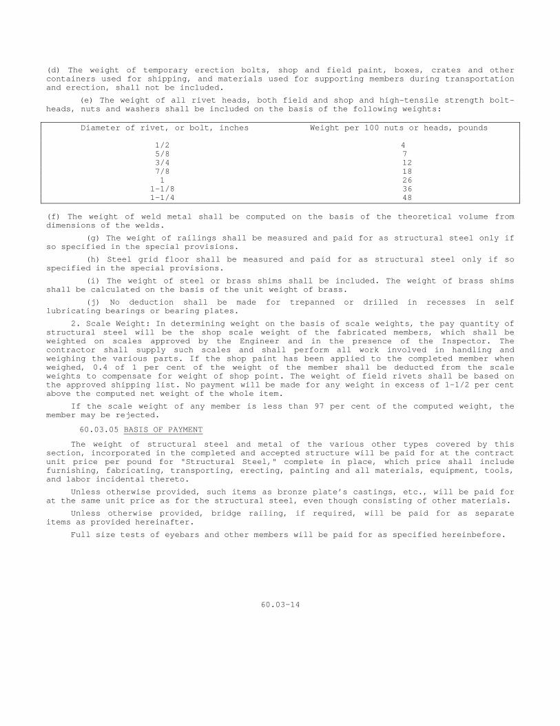
(d) The weight of temporary erection bolts, shop and field paint, boxes, crates and other containers used for shipping, and materials used for supporting members during transportation and erection, shall not be included.
(e) The weight of all rivet heads, both field and shop and high-tensile strength bolt-heads, nuts and washers shall be included on the basis of the following weights: Diameter of rivet, or bolt, inches Weight per 100 nuts or heads, pounds 1/2 4 5/8 7 3/4 12 7/8 18 1 26 1-1/8 36 1-1/4 48 (f) The weight of weld metal shall be computed on the basis of the theoretical volume from dimensions of the welds.
(g) The weight of railings shall be measured and paid for as structural steel only if so specified in the special provisions.
(h) Steel grid floor shall be measured and paid for as structural steel only if so specified in the special provisions.
(i) The weight of steel or brass shims shall be included. The weight of brass shims shall be calculated on the basis of the unit weight of brass.
(j) No deduction shall be made for trepanned or drilled in recesses in self lubricating bearings or bearing plates.
2. Scale Weight: In determining weight on the basis of scale weights, the pay quantity of structural steel will be the shop scale weight of the fabricated members, which shall be weighted on scales approved by the Engineer and in the presence of the Inspector. The contractor shall supply such scales and shall perform all work involved in handling and weighing the various parts. If the shop paint has been applied to the completed member when weighed, 0.4 of 1 per cent of the weight of the member shall be deducted from the scale weights to compensate for weight of shop point. The weight of field rivets shall be based on the approved shipping list. No payment will be made for any weight in excess of 1-1/2 per cent above the computed net weight of the whole item.
If the scale weight of any member is less than 97 per cent of the computed weight, the member may be rejected.
60.03.05 BASIS OF PAYMENT
The weight of structural steel and metal of the various other types covered by this section, incorporated in the completed and accepted structure will be paid for at the contract unit price per pound for "Structural Steel," complete in place, which price shall include furnishing, fabricating, transporting, erecting, painting and all materials, equipment, tools, and labor incidental thereto.
Unless otherwise provided, such items as bronze plate’s castings, etc., will be paid for at the same unit price as for the structural steel, even though consisting of other materials.
Unless otherwise provided, bridge railing, if required, will be paid for as separate items as provided hereinafter.
Full size tests of eyebars and other members will be paid for as specified hereinbefore.
60.03-14
SECTION 60.04 PREFORMED JOINT FILLER FOR STRUCTURES
60.04.01 DESCRIPTION This item shall include joint filler for use in bridges, culverts, buildings, walls, pavements and other miscellaneous construction as required. The joint filler shall be prepared and constructed in accordance with these specifications, at the locations and of the type and thickness shown on the plans or as directed by the Engineer. 60.04.02 MATERIALS Preformed joint filler shall conform to the requirements of, and be used at locations in accordance with the provisions of Section 2.15 of these specifications unless otherwise called for in the special conditions or on the contract plans. 60.04.03 CONSTRUCTION METHODS Joint filler shall be installed in joints according to details shown on the plans and the directions of the Engineer. The joint filler shall be placed in correct position as the concrete on one side of the joint is placed. When the form is removed, the concrete on the other side of the filler shall be placed against it. 60.04.04 METHOD OF MEASUREMENT Joint filler will be measured by the area, in square feet, of the joint filler, of the type and thickness specified, actually installed and accepted. 60.04.05 BASIS OF PAYMENT Joint filler will be paid for at the contract unit price per square foot for "Preformed Joint Filler" of the type and thickness specified, complete in place, which price shall include all materials, equipment, tools, labor and work incidental thereto.

60.04-1
SECTION 60.05 MEMBRANE WATERPROOFING (WOVEN GLASS FABRIC)
60.05.01 DESCRIPTION
This item shall consist of furnishing and applying a membrane system of waterproofing to the surface of concrete structures where a wearing surface is to be constructed, at construction joints and at other locations shown on the plans or ordered.
60.05.02 MATERIALS
The materials for this work shall conform to the requirements of Article 2.13 for primer, woven glass fabric saturated with asphalt, seal coat, and for asphalt flashing cement.
60.05.03 CONSTRUCTION METHODS
Concrete surfaces which are to be waterproofed shall be smooth, free from projections or holes which might cause puncturing of the membrane fabric. The surface shall be thoroughly cleaned of loose or foreign substances.
No priming or waterproofing shall be done in wet weather nor when the temperature of the air or concrete surface is below 35 degrees F., without special authorization from the Engineer.
Unless otherwise directed, construction joints above those at the footings of abutments, wing walls, retaining walls, etc., shall be made impervious to water by the application of membrane waterproofing on the unexposed surface for a distance of 18 inches on each side of the joint.
1. Primer: Beginning at the low point of the surface to be waterproofed, the primer shall be applied in one coat at a rate of about 1/10 gallon per square yard and allowed to cure for approximately 24 hours before the waterproofing membrane is applied.
2. Membrane Fabric: The waterproofing fabric and the seal coat shall be applied as follows:
The asphalt shall be heated to a temperature of about 300 degrees F. (not over 350 degrees F.) with frequent stirring to avoid local overheating. The heating kettles shall be equipped with approved thermometers.
Waterproofing shall begin at the low point of the surface so that water will run over and not against or along the laps. A section about 20 inches wide and the full length of the surface shall be mopped with hot asphalt, and a strip of fabric of 1/2 width shall be rolled into it, pressed into place to eliminate all air bubbles and to obtain close conformity with the surface. This strip and an adjacent section of the surface of a width of the fabric being used, shall then be mopped with hot asphalt, and a full width of fabric rolled into it, completely
60.05-1
covering the first strip and pressed into place as before. This second strip and adjacent section of the concrete surface shall then be mopped with hot asphalt and the next succeeding strips of fabric "shingled” on so that there will be 2 layers of fabric at all points with laps not less than 2 inches wide. All end laps shall be at least 12 inches.
This process shall be continued until the entire surface to be waterproofed has been covered. The fabric shall than be given a final mopping of hot asphalt. The mopping on concrete shall cover the surface so that no gray spots appear, and on fabric it shall be sufficiently heavy to completely conceal the weave. Special care shall be taken that all laps are thoroughly sealed down.
To insure a water-tight joint between the deck slab and the curb, asphalt flashing cement shall be applied to the joint for a distance of approximately 2 inches up on the curb and 2 inches out on the deck after the primer has set up and before the membrane is started. After the final mopping of the membrane, an additional coat of asphalt flashing cement shall be applied to the top edge of the membrane waterproofing to completely cover the fabric and to seal the joint made with the curb.
Care shall be taken to prevent injury to the finished membrane by the passage over it of men or equipment. Any damage which may occur shall be repaired by patching. Patches shall extend at least 12 inches beyond the outermost damaged portion and the second ply shall extend at least 3 inches beyond the first.
60.05.04 METHOD OF MEASUREMENT
The quantity to be paid for under this item will be the number of square yards of waterproofed surface in the completed and accepted work.
60.05.05 BASIS OF PAYMENT
This item will be paid for at the contract unit price per square yard for "Membrane Waterproofing (Woven Glass Fabric)" which price shall be full compensation for furnishing all material, equipment, labor and incidentals necessary to complete the item.
PAY ITEM PAY UNIT Membrane Waterproofing S.Y.
60.05-2
SECTION 60.06 DAMPPROOFING
60.06.01 DESCRIPTION Dampproofing of concrete or masonry work shall consist of a coating of asphalt constructed as indicated on the plans and in accordance with these specifications. The type of bitumen to be used will be determined by the Engineer. 60.06.02 MATERIALS The materials for this work shall conform to the following requirements:
1. Asphalt for primer and seal coat shall conform to the requirements of Article 2.13.
60.06.03 CONSTRUCTION METHODS The surface to which the dampproofing coating is to be applied shall be cleaned of all loose and foreign material and dirt and shall be dry. Where necessary, the Engineer may require the surface to be scrubbed with water and a stiff brush, after which the surface shall be allowed to dry before the application of the primer. Concrete, brick or other surfaces which are to be protected by dampproofing shall be thoroughly clean and dry before the primer is applied. One coat of asphalt primer shall be applied at the rate of 1/8 gallon to each square yard of surface. On the well-primed surface one application of asphalt seal coat shall be applied at the rate of 1/10 gallon per square yard. Care shall be taken to confine all applied material to the areas to be dampproofed and to prevent disfigurement of any other parts of the structure by dripping or spreading. 60.06.04 METHOD OF MEASUREMENT This work will be measured for payment by the number of square yards of dampproofing, consisting of primer and seal cost, completed and accepted within the neat lines shown on the plans or as ordered by the Engineer. 60.06.05 BASIS OF PAYMENT This work will be paid for at the contract unit price per square yard for "Dampproofing", complete in place, including all material, equipment, tools, labor and incidental expense.

60.06.1
SECTION 61.01 COFFERDAM
61.01.01 DESCRIPTION The work under this item shall consist of the construction of a cofferdam, the necessary dewatering of same, and the removal of all temporary structures and facilities upon completion of the permanent work. For the purpose of this work, cofferdam shall be understood to mean any temporary type construction which the contractor elects to build to satisfy the condition that all concrete work is to be done in the dry. The Contractor shall submit to the Engineer plans showing his proposed method of cofferdam construction prior to the start of such construction. The furnishing of such plans and methods shall not serve to relieve the contractor of any of his responsibility for the safety of the work or the responsibility for the successful completion of this project. 61.01.02 MATERIALS Not applicable. 61.01.03 CONSTRUCTION METHODS The cofferdam shall be carried to adequate depths and heights shall be safely designed and as watertight as necessary for the proper performance of the work inside it. No part of the cofferdam shall be left in such a way as to extend into the new wall. Pumping to maintain a dry condition during construction of the wall shall be provided by the Contractor. It shall be considered as work incidental to the cofferdam and no separate payment will be made. All parts of the cofferdam are to be removed after completion of the wall and after the concrete has set for a period of time to be determined by the Engineer. Care shall be taken not to disturb or otherwise injure any permanent construction during removal of the cofferdam. 61.01.04 and 61.01.05 METHOD OF MEASUREMENT AND BASIS OF PAYMENT The work under this item will not be measured for payment but will be paid for at the contract lump sum price for "COFFERDAM", which price shall include all materials, tools, equipment, labor and work incidental thereto.

61.01-1
SECTION 61.02 PATCH APPROACH SPAN ROADWAY FLOORING
61.02.01 DESCRIPTION Work under this item shall consist of furnishing all labor, materials, tools and equipment necessary to completely remove and rebuild deteriorated and unsound portions of existing concrete fill in the existing roadway grating, all as specified herein or as directed by the Engineer. In cases where, in the opinion of the Engineer, it is necessary to completely remove and replace, within the repair area, existing deteriorated steel plate attached to the bottom of the existing grating, the Engineer will order, in writing, that such be done, in which case, payment for repairs will be made under the contract item "Repair Approach Span Roadway Flooring". In all other cases, repairs to the approach span roadway flooring will be paid for under the item "Patch Approach Span Roadway Flooring". 61.02.02 MATERIALS Patching and fill material shall be non-shrink mortar or concrete mixed to the stiffest practical consistency and in the proportions recommended by the manufacturer, and approved by the Engineer, for the use intended. Non-shrink material shall be "Embeco" as manufactured by Master Builders of Cleveland Ohio or "Vibro-Foil" as manufactured by W.R. Grace & Co. of Cambridge, MA or approved equal. The aggregate and cement used in the mortar and concrete shall conform to Section 2.07 of these specifications. The aggregate shall be well graded with maximum size of 3/8" and 1/4 of the depth of the patch or fill, whichever is smaller. Curing compound shall be "Horn Clear Seal" as manufactured by W.R. Grace & Co., or approved equal. Bonding agent for concrete shall be "Daraweld-C" as manufactured by W.R. Grace and Co., or approved equal, and formulated for exterior use. 61.02.03 CONSTRUCTION METHOD All existing unsound and semi-unsound concrete grating fill, at locations designated by the Engineer, shall be removed from the roadway flooring by chipping or by other approved methods in such a way as to not damage the steel grating, steel underplate, welds, that concrete fill which is to remain in place, or the bond between the concrete fill which is to remain and the steel. Sound concrete fill shall be removed when required so as to construct a patch of 3/4 inch minimum thickness, as measured from the top of the grating to the bottom of the patch. The area to be patched or filled is to be cleaned of oil, grease, loose material and all foreign matter. Sand blasting, wire brushing (by machine or hand), or surface treating with 1:1 muriatic acid solution (approximately 14%) will be employed where required to insure adequate cleaning.
61.02-1 CAUTION: Acid must be thoroughly flushed off all portions of the structure as it will corrode concrete and steel and destroy bonding of patch and fill material. Surface residue of dust, and dirt shall be removed by vacuuming, brooming or high pressure water or air treatment. Bonding agent shall be applied to all existing surfaces to be in contact with the patch or fill material, in accordance with directions of the manufacturer and as approved by the Engineer. The patching and fill material is to be placed when the bonding agent is properly set in accordance with manufactures directions. The water content of the material shall be as low as possible and still permit proper placement. No more material shall be mixed than can be used in approximately twenty minutes under normal conditions of temperature, etc., and once initial set has taken place retempering by adding water will not be permitted. The patching and fill material shall be mixed, placed, and finished in accordance with applicable provisions of Section 70.22, Concrete for Structure, and with the directions of the Engineer. Curing compound shall be sprayed on patched and filled surfaces within approximately 1-2 hours after completion of finishing operations and/or immediately after disappearance of the "sheen" of surface moisture. Care shall be exercised not to contaminate adjacent surfaces against which material is to be subsequently bonded. The surfaces are to be coated uniformly, leaving no pinholes or gaps, at a rate not exceeding 300 sq. ft. per gallon. Care must be exercised not to leave a heavy surface film. A second coat of the curing compound shall be applied after the first coat is allowed to dry overnight. The surface treatment is to be "hard" before traffic of any kind is allowed on it. In addition to curing provided by the curing compound, all areas subject to traffic abrasion shall be wet down with fresh water at intervals sufficient to prevent the new surface from drying out for a period of at least five days. 61.02.04 METHOD OF MEASUREMENT This work will be measured for payment by the number of square feet of patched or filled roadway area completed and accepted within the neat lines designated in the field by the Engineer. 61.02.05 BASIS OF PAYMENT This work will be paid for at the contract unit price per square foot for "Patch Approach Span Roadway Flooring", complete in place, which price shall include the cost of all labor, materials, equipment and tools necessary for the satisfactory completion of the work. The cost of repairs, as approved by the Engineer, to steel grating and bottom plate which are damaged by the contractor shall not be paid for separately but such cost shall be included in the cost of item "Patch Approach Roadway Flooring".

61.02-2
SECTION 61.03 REPAIR APPROACH SPAN ROADWAY FLOORING
61.03.01 DESCRIPTION
Work under this item shall be done in areas designated by the Engineer only when ordered in writing by the Engineer prior to the start of the work. The work shall consist of furnishing all labor, materials, tools, and equipment necessary to completely remove and reconstruct all the existing concrete fill within the designated repair area of the existing roadway grating; and also, to completely remove and reconstruct, within the designated repair area, existing deteriorated steel plate welded (or otherwise attached) to the bottom of the existing grating.
The steel underplate will be ordered removed and reconstructed, in writing, only if it is in a deteriorated condition. Otherwise, repairs to the roadway flooring shall be made in accordance with Section 61.02 of these specifications.
61.03.02 MATERIALS
Fill material, aggregate and cement, curing compound, and bonding agent shall conform to Article 61.02.02 of these specifications.
Metals shall conform to applicable provisions of Section 2.11. All metals (including welds, rivets, etc.) are to be reconstructed with their equal unless shown otherwise on the plans or directed otherwise by the Engineer.
Paint shall conform to applicable provisions of Section 2.12. The painting system used shall be equal to that in the original construction unless specified otherwise by the Engineer or in these contract documents.
61.03.03 CONSTRUCTION METHODS
All existing concrete grating fill, at locations designated by the Engineer, shall be removed from the roadway flooring by approved methods and in such a way as to not damage the steel grating, the concrete adjacent to the repair area which is to remain in place (including its bond to the steel flooring) or the existing welds and connections which are to remain.
Designated portions of deteriorated existing steel plate welded (or otherwise attached) to the bottom of the existing grating shall be removed and reconstructed as directed by the Engineer.
All work on steel, including painting, shall be in accordance with Article 60.03.03 of these specifications and/or directed by the Engineer.
Steel shall be cleaned, bonding agent applied, and the fill material cured, as specified in Article 61.02.03 of these specifications and/or ad directed by the Engineer.
The grating fill material shall be mixed, placed and finished in accordance with applicable provisions of Section 70.22, Concrete for Structures, and with the directions of the Engineer.
61.03.04 METHOD OF MEASUREMENT
This work, at locations designated in writing by the Engineer, will be measured for payment by the number of square feet of newly filled roadway area under which the existing underplate has been reconstructed, all completed and accepted within the neat lines designated in the field by the Engineer.
61.03.05 BASIS OF PAYMENT
This work will be paid for at the Contract unit price per square foot for "Repair Approach Span Roadway Flooring", complete in place, which price shall include the cost of all labor, materials, equipment and tools necessary for the satisfactory completion of the work.
61.03-1
61.03-1
SECTION 61.04 RECONSTRUCT CONCRETE OVERLAY
61.04.01 DESCRIPTION
The work under this item shall consist of furnishing all labor, equipment, materials, and tools required to:
(a) Remove and dispose existing reinforced concrete overlays or portions thereof,
(b) Remove and reconstruct membrane waterproofing,
(c) Construct or reconstruct joint filler, reinforcing steel, joint seal, and joint seal bond breaker,
(d) Apply bonding agent, where required,
(e) Mix place, finish, and cure concrete, or patching material,
(f) Construct overlay underdrains,
All as detailed on the plans and required by these specifications and the Engineer.
61.04.02 MATERIALS
Membrane waterproofing shall conform to the requirements of Article 60.05.02 of these specifications.
Concrete shall be Class B(AE) concrete conforming to the requirements of Section 2.07 of these specifications.
Metals shall conform to applicable provisions of Sections 2.11. All metals shall be reconstructed with their equal unless shown otherwise on the plans or directed otherwise by the Engineer.
Preformed joint filler shall be the size and type shown on the plans and shall conform to Article 2.15.01 of these specifications.
Joint sealer shall conform to the requirements of Article 2.15.07 of these specifications.
Joint sealer bond breaker shall conform to the requirements of Article 2.15.10 of these specifications.
Patching material (including its aggregate and cement) shall conform to the requirements of Article 61.02.02 of these specifications.
Bonding agent shall be Thiopoxy 62, as manufactured by W.R. Grace and Co., or approved equal.
Curing compound shall be "Horn Clear Seal", as manufactured by W.R. Grace and Co., or approved equal.
Tubing and sheet metal form for overlay underdrain shall be of copper and shall be approved by the Engineer.
61.04.03 CONSTRUCTION METHODS
(a) Partial Overlay Reconstruction: When only a deteriorated portion of an overlay is to be removed and reconstructed, the perimeter of that portion shall be saw cut along the neat lines designated in the field by the Engineer. The patched portion of the overlay shall be removed for its full depth unless directed otherwise by the Engineer. Care shall be exercised not to cut or damage existing reinforcing bars, wire mesh, or membrane waterproofing which is to remain in place. Damaged or ineffective membrane waterproofing shall be patched or, at the option of the Engineer, removed and reconstructed within the patch area. All work done to reconstruct the designated portion of overlay shall be in accordance with applicable provisions of Article 61.04.03(b), Article 61.01.03, and in accordance with the directions of Engineer and applicable details shown on the plans.
61.04-1
61.04-1
(b) Complete Overlay Reconstruction: The existing reinforced concrete overlay shall be broken up into pieces by suitable and approved means and acceptably disposed of. Care must be exercised not to impair the integrity of retained portions of the structure. All operations necessary for the removal of the overlay which might endanger new construction shall be completed prior to the construction of the new work. The use of equipment or other devices, which might damage or injure structures, facilities, or property which is to be preserved and retained will not be permitted.
The existing membrane waterproofing is to be removed and the surfaces to be overlaid, or bonded to, shall be cleaned of all foreign matter in a manner acceptable to the Engineer.
Membrane waterproofing shall be constructed in accordance with applicable provisions of Article 60.05.03 of these specifications.
Preformed joint filler shall be constructed in accordance with applicable provisions of Article 60.04.03 of these specifications.
Concrete joint sealer, and joint sealer bond breaker shall be constructed in accordance with applicable provisions of Article 60.01.03 of these specifications.
Reinforcing steel shall be constructed in accordance with applicable provisions of Article 60.02.03 of these specifications.
Curing compound shall be constructed in accordance with applicable provisions of Article 61.02.03 of these specifications.
(c) Overlay Underdrain: After the existing overlays have been removed and before the new membrane waterproofing is constructed, neat, one and one-half (1-1/2) inch diameter, diamond drilled scupper holes shall be drilled through the structural slab at the locations shown on the plans or designated in the field by the Engineer.
Each existing structural slab shall be carefully chipped, where required, such that its low point drains toward the scupper. Chipping over one quarter (1/4) inch deep shall be approved by the Engineer and no more chipping shall be done than is absolutely necessary.
A bituminous coated copper tube, of length to be determined in the field, shall be press fitted into each drill hole to the position shown on the plans while the coating is still fluid.
Membrane waterproofing shall be carefully constructed around each drill hole as shown on the plans, in accordance with applicable provisions of Article 60.05.03, and as directed by the Engineer.
A copper sheet metal form shall be mechanically secured in place in such a way as to prevent concrete from entering each drill hole and such that no cavity will exist underneath the forms which will weaken the completed overlay slab. The form shall be placed, shaped and cut as required so water cannot accumulate on it and the edge of the form shall be irregular such that seepage water may pass underneath it and enter the scupper.
61.04.04 METHOD OF MEASUREMENT
This work shall be measured for payment by the number of square feet of overlay reconstruction; complete and accepted within the neat lines designated in the field by the Engineer.
No distinction shall be made between "partial" and "complete" overlay reconstruction and no measurement will be made for overlay underdrain construction.
61.04.05 BASIS OF PAYMENT
This work shall be paid for at the contract unit price per square foot for "Reconstruct Concrete Overlay", which price shall include the cost of all materials, equipment, tools, and labor necessary for the satisfactory completion of all the work required under this section. No separate payment will be made for construction of the overlay underdrain, complete as directed and as detailed on the contract plans, but such cost shall be included in the contract unit price per square foot for "Reconstruct Concrete Overlay".
61.04-2
61.04-2
SECTION 61.05 SIDEWALK RECONSTRUCTION
61.05.01 DESCRIPTION
The work under this item shall consist of furnishing all labor, equipment, material, and tools required to
(a) Remove, for their full width, and dispose defective sidewalk slabs.
(b) Construct or reconstruct reinforcing steel, (including welding) slab support anchor bolts,
(c) Apply bonding agent where required,
(d) Mix, place, finish, and cure concrete,
(e) Install joint sealer, and joint sealer bond breaker,
(f) Paint new structural steel,
All as detailed on the plans and required by these specifications and the Engineer.
The sidewalks are to be removed and reconstructed only when ordered by the Engineer and when the underlying concrete is not found to be solid after the deteriorated top surface is removed. Otherwise the sidewalks are to be patched in accordance with Section 61.09 of these specifications.
61.05.02 MATERIALS
Concrete shall be Class B(AE) concrete conforming to the requirements of Section 2.07 of these specifications except that the concrete which is placed under the horizontal surface of the existing curb and above the reinforcing steel shall be Class B(AE) concrete with the amount of water reduced to produce a "dry pack" consistency, or as ordered by the Engineer, and all other concrete is to have a maximum slump of two (2) inches. Metals shall conform to applicable provisions of Section 2.11. All metals which are removed from the structure shall be replaced with their equal unless shown otherwise on the plans or directed otherwise by the Engineer.
Anchor bolts shall be three-fourths (3/4) inch diameter "Red Head" concrete anchors as manufactured by the Phillip's Drill Company, Michigan City, Indiana or approved equal. The anchor and expander plugs are to be double plated to provide thorough rust protection.
Bonding agent shall be Thiopoxy 62, and curing compound shall be "Horn Clear Seal", as manufactured by W.R. Grace and Co., or approved equal.
Joint sealing compound shall conform to the requirements of Article 2.15.07 of these specifications.
Joint sealer bond breaker shall conform to the requirements of Article 2.15.10 of these specifications.
Paint shall conform to applicable provisions of Section 2.12 of these specifications.
61.05.03 CONSTRUCTION METHODS
Only sections of sidewalk specifically designated in the field by the Engineer are to be removed and reconstructed. The sidewalk is to be removed and reconstructed for its full width, as shown on the plans. The concrete along the perimeter of the sections to be reconstructed shall be sawcut to a depth of approximately one (1) inch, along neat lines to be designated by the Engineer. Where sawcutting cannot be done, other approved methods shall be used which will result in clean, neat, edges and side surfaces all acceptable to the Engineer. In no case shall reinforcing steel along the perimeter be cut.
61.05-1 The designated sections of sidewalk shall be removed by suitable and approved means and
acceptably disposed. Care must be exercised not to impair the integrity of retained portions
of the structure. All operations necessary for the removal of the sidewalk which might endanger new construction shall be completed prior to the construction of the new work. The use of equipment or other devices which might damage or injure structures, facilities, or property which is to be preserved and retained will not be permitted.
If the existing reinforcing steel in the sidewalk if found to be in good condition and the Contractor chooses to leave it in place, it shall be cleaned of all mortar, concrete, detrimental rust, and other foreign matter in a manner to be approved by the Engineer. Where the contractor elects to remove the existing reinforcing steel, he shall replace it and reconstruct it with its equal or as directed by the Engineer.
Where reinforcing steel is not found to be in good condition, the section of sidewalk to be reconstructed shall be widened, if necessary, and as directed, so that at least a four (4) inch length of each reinforcing bar, which is exposed and which extends into the reconstruction section is found to be sound. All corroded reinforcing steel shall be removed and replaced with new reinforcing steel of equal size and spacing or as directed by the Engineer.
Construction of all reinforcing steel shall be performed in accordance with details shown on the plans, the directions of the Engineer, and applicable provisions of Article 60.02.03 of these specifications. Portions of the existing structure which required supporting shall be so provided.
Construction procedures for cleaning all surfaces which are to be in contact with the new concrete, for applying bonding agent to existing concrete surfaces, and for mixing, placing, finishing, and curing the new concrete shall be in accordance with Article 61.02.03 of these specifications.
All existing structural and miscellaneous steel, including their anchors into the concrete, which is damaged by the Contractor shall be repaired or replaced by the Contractor as required by the Engineer, at no cost to the City.
All structural steel, including painting, shall be constructed in accordance with Article 60.03.03 of these specifications and as directed by the Engineer.
Concrete anchors shall be installed in accordance with manufacturer's directions and as approved by the Engineer.
Joint sealer and joint sealer bond breaker shall be constructed in accordance with applicable provisions of Article 60.01.03 of these specifications.
61.05.04 METHOD OF MEASUREMENT
This work shall be measured for payment by the number of lineal feet of full width sidewalk which is acceptably reconstructed, in accordance with the provisions of this section, within the neat lines designated in the field by the Engineer.
Measurement shall be made parallel to the longitudinal centerline of the bridge. A distinction shall be made between measurements of the approach span sidewalk reconstruction and the bascule pier sidewalk reconstruction.
61.05.05 BASIS OF PAYMENT
This work shall be paid for at the contract unit price per lineal foot for "Reconstruct Bascule Pier Sidewalk" or "Reconstruct Approach Span Sidewalk", whichever is applicable, which price shall include the cost of all labor, materials, equipment and tools necessary for the satisfactory completion of the work.
The cost of all structural and miscellaneous steel (including anchor bolts), except that damaged by the Contractor and repaired or replaced by him, shall be paid for at the contract unit price for "Structural Steel".
All costs of excavation (chipping, etc.) done on slabs which are later ordered removed and reconstructed, in accordance with this section, shall not be paid for separately but such costs shall be included in the contract unit prices for the work done under this section.
61.05-2
SECTION 61.06 RECONSTRUCT BASCULE SPAN SIDEWALK FLOORING
61.06.01 DESCRIPTION The bascule span sidewalk flooring shall consist of a steel grid, assembly (grid, bottom plate, and attached misc. steel), filled with non-shrink mortar. The work under this section shall consist of furnishing all labor, equipment, materials, and tools required to (a) Remove, dispose, and reconstruct existing sidewalk flooring including fill, (b) Seal all transverse joints between flooring units, (c) Cure fill material, (d) Paint new structural and miscellaneous steel. All as detailed on the plans and required by these specifications and the Engineer. 61.06.02 MATERIALS Steel grating shall be Irvico-Grating Prod. type "WH", or approved equal, with 1" x 3/16" bearing bars and 3/4" x 1/8" reticuline bars. Steel shall contain not less than 0.2% copper and shall conform to the requirements of Section 2.11 of the specifications, and to the requirements of A.S.T.M. A36. Fill material shall be non-shrink mortar mixed to the stiffest practical consistency and in the proportions recommended by the manufacturer, and approved by the Engineer, for the use intended. Non shrink material shall be "Embeco" as manufactured by Master Builders of Cleveland, Ohio or "Vibra-Foil" as manufactured by W.R. Grace & Co., of Cambridge, MA or approved equal. The aggregate and cement used in the mortar shall conform to Section 2.07 of these specifications. The aggregate shall be well graded with maximum size of one-quarter (1/4) of an inch. Curing compound shall be "Horn Clear Seal," as manufactured by W.R. Grace & Co., or approved equal. Joint sealer shall conform to the requirements of Article 2.15.07 of these specifications. Joint sealer bond breaker shall conform to the requirements of Article 2.15.10 of these specifications. Paint shall conform to the requirements of Section 2.12 of these specifications. 61.06.03 CONSTRUCTION METHOD All defective sidewalk flooring shall be removed, at locations designated 61.06-1
61.06-1
by the Engineer, by approved methods and in such a way as to not impair the integrity of retained portions of the structure. The use of equipment or other devices which might damage or injure structures, facilities, or property which is to be preserved and retained will not be permitted. All material removed must be acceptably disposed. Flooring shall be fabricated in units of approved size which shall be field spliced as shown on the plans. Longitudinal joints in the bottom plate between adjacent units shall be sealed with welds so as to be watertight. All welding of component parts of the flooring and of the flooring to its supports and all other steel construction work shall conform to the requirements of Section 60.03.03 (34) of these specifications. The underside of the flooring and the outer faces of header bars and angles and top surfaces of end angles shall receive the shop and field painting specified for structural steel, Article 60.03.03 (58) and (59). Other surfaces shall not be painted or oiled, but shall be thoroughly cleaned of rust and scale before the mortar filling is placed. Fill material shall be mixed, placed and finished in accordance with applicable provisions of Section 60.01.02 (c) and shall be cured as specified in Article 61.02.03 of these specifications and as directed by the Engineer. Fill material shall be placed starting at the centerline of the bascule span and is to proceed continuously toward the trunnions. Four test cubes shall be case of each pour of the fill material and they shall be cured under job conditions. They shall be tested, two at a time, at intervals to be determined by the Engineer. Strain of the bascule span sidewalk shall be prevented until the mortar fill has developed a minimum compressive cube strength of 3800 psi, using A.A.S.H.O. T-106-60 testing procedures. Joint sealer and joint sealer bond breaker shall be constructed in accordance with applicable provisions of Article 60.01.02 (d) of these specifications. All existing parts of the structure, including paint, which are to remain in place and which are damaged by the Contractor shall be repaired or replaced by the Contractor, as required by the Engineer, at no cost to the City. Hidden areas which are exposed by the Contractor, shall be painted, if required, at no added cost to the City. 61.06.04 METHOD OF MEASUREMENT The work performed under this section shall be measured for payment by the number of square feet of surface area of sidewalk reconstructed, complete in place and accepted by the Engineer. 61.06.05 BASIS OF PAYMENT This work shall be paid for at the contract unit price per square foot for "Reconstruct Bascule Span Sidewalk Flooring", which price shall include the cost of all labor, materials, equipment and tools necessary for satisfactory completion of the work required by this section.
61.06-2

61.06-2
61.06-3
SECTION 61.07 CUT GROOVES AND SEAL JOINTS
61.07.01 DESCRIPTION Work under this item shall consist of furnishing all labor, materials, tools, and equipment necessary to cut grooves along existing joints and to fill the groove with joint sealing compound, all as shown on the plans and as directed by the Engineer. Grooves which can be formed in new concrete, and filled with sealing compound, are not included in this item. 61.07.02 MATERIALS Joint sealer shall conform to the requirements of Article 2.15.07 of these specifications. Joint sealer bond breaker shall conform to the requirements of Article 2.15.10 of these specification. 61.07.03 CONSTRUCTION METHODS All machines, tools and equipment used in the performance of the work required by these specifications shall be subject to the approval of the Engineer. Grooves shall be sawcut along existing joints in the position, to the dimensions, and at the locations shown on the plans and designated by the Engineer. Where sawcutting cannot be done, other approved methods shall be used which will result in neat, clean, solid, edges and side surfaces, all acceptable to the Engineer. In no case shall reinforcing steel be cut. Joint sealer and joint sealer bond breaker shall be constructed in accordance with applicable provisions of Article 60.01.02 (d) of these specifications. 61.07.04 METHOD OF MEASUREMENT This work shall be measured for payment by the number of lineal feet of groove which is cut and filled, complete, as required and accepted by the Engineer. 61.07.05 BASIS OF PAYMENT The work required under this section will be paid for at the contract unit price per lineal foot for "Cut Grooves and Seal Joints", complete as required and accepted, which price shall include the cost of all equipment, tools, materials, and labor necessary for the satisfactory completion of the work. Work required to form and fill grooves in new concrete construction is not to be paid for under this item, but such cost is to be included in the cost of the new concrete construction unless otherwise stipulated in these specifications.

61.07-1
SECTION 61.08 FIELD PAINTING OF METALS
61.08.1 DESCRIPTION This item of work shall consist of furnishing all labor, materials, tools and equipment necessary to paint non-galvanized metal surfaces as shown on the contract drawings, as directed by the Engineer, and in conformance with the contract specifications. 61.08.02 MATERIALS Paint materials shall conform to the requirements of Section 2.12 of the contract specifications and to the following special requirements: 1. Red Primer - The initial primer coat shall be "Rust-Oleum No. 1069-Heavy Duty Rust-Inhibitive Red Primer" as manufactured by the Rust-Oleum Corporation, Evanston, Illinois or approved equal. 2. Intermediate Primer - The second primer coat shall be "Rust-Oleum No. 1060-Heavy-Duty Rust Inhibitive Intermediate Primer" as manufactured by the Rust-Oleum Corporation, Evanston, Illinois or an approved equal. 3. Finish Coat - The final coat shall be a "Rust-Oleum-New Color Horizons Finish Coat, High Gloss Finish as manufactured by the Rust-Oleum Corporation, Evanston, Illinois, or an approved equal, color to be as shown on the contract drawings or as ordered by the Engineer. 61.08.3 CONSTRUCTION METHODS (1) Surface Preparation All greasy and oily residues shall be removed from all metal to be painted by wiping or scrubbing with rags or brushes wetted with solvent. All surfaces to be painted shall be clean and free of loose dirt, dust or grit before painting is started. Rust, loose mill scale, and other detrimental matter shall be removed by sanding, wire brushing, chipping, or blast cleaning as indicated on the contract drawings and as directed by the Engineer. The prepared surface shall be blasted free of grit, dust, and corrosion products prior to painting, which shall be undertaken before corrosion commences, in no case within more than eight hours. Any damage to shop coats caused during cleaning, repairing, or erecting shall be spot-primed with red primer. (2) Application of paint All paint shall be well dispersed and shall not exhibit hard settling or skinning in the can, nor show any evidence of caking or livering. 61.08-1
61.08-1
Application will not be allowed when it is raining or immediately after rain before the surfaces have had a change to dry, or when rain threatens, Painting will not be permitted when the relative humidity exceeds 85%. No paint shall be applied upon surfaces that are wet from condensation, ice, or any other causes.
No painting will be allowed when the outside air temperature falls below 45o F. Thinning of paint, in accordance with the manufacturer's instructions will be allowed only upon approval by the Engineer. Paint may be applied by brush, roller, or spray; the dry film thickness of each of the three coats shall be at least 1 mil and not more than 2 mils. Paint shall be evenly spread and flowed on without runs, sags, or excessive brush marks. For all applied coats, a stripe coating shall first be applied to sharp edges (angles, rivet or bolt heads, corners, and juncture of lap joints, etc.) after which a full coat to all surfaces shall be applied. All coats shall be thoroughly dry, to the satisfaction of the Engineer, before succeeding coats are applied. (3) Protection and Storage The Contractor shall protect all adjacent work, materials, and surfaces with suitable covers during the progress of the work. The Contractor shall be liable for damages to existing areas. Upon completion of the work, all staging, scaffolding, containers, equipment and materials shall be removed from the site. Paint spots, spills, oils, or stains upon adjacent surfaces and equipment shall be removed to the satisfaction of the Engineer. 61.08.4 METHOD OF MEASUREMENT This item of work will not be measured for payment. 61.08.5 BASIS OF PAYMENT This item of work will be paid for at the contract lump sum price for "Field Painting of Metals" which price shall include the cost of all labor, materials, equipment and incidental work necessary for the satisfactory completion of the work as shown in the contract drawings and specifications and as directed by the Engineer.
61.08-2

61.08-2
61.08-3
SECTION 61.09 CONCRETE PATCHING
61.09.01 DESCRIPTION The work under this section shall consist of furnishing all labor, equipment, and materials necessary to complete all deep and shallow concrete patching at the locations and within the neat lines designated in the field by the Engineer. Patch locations shown on the plans are approximate only and shall not be interpreted to indicate the exact area to be patched. All work shall be done in accordance with the plans, specifications, and the directions of the Engineer. 61.09.02 MATERIALS Patching material, aggregate and cement, and curing compound shall conform to the requirements of Article 61.02.02 of these specifications. Bonding agent shall be Thiopoxy 62, as manufactured by W.R. Grace & Company, or approved equal. Metals shall conform to applicable provisions of Section 2.11. All metals are to be reconstructed with their equal unless shown otherwise on the plans or directed otherwise by the Engineer. 61.09.03 CONSTRUCTION METHODS Patching shall be done only in areas designated in the field by the Engineers. The perimeter of the patch area shall be sawcut to a depth of approximately one (1) inch, as shown on the plans, along the neat lines to be designated by the Engineer. In no case shall reinforcing steel along the perimeter be cut. All interior corners are to be rounded with a one (1) inch radius. All deteriorated and partially deteriorated concrete within the patch area shall be removed by chipping, or by other approved methods, in such a way as to not damage portions of the concrete and steel which is to remain in place. Sound concrete is to be removed only when required to obtain a one (1) inch minimum patch thickness for shallow repairs, or, for deep repairs, to obtain the minimum patch thickness which provides a three-fourths (3/4) inch minimum clearance on the bottom of reinforcing bars, all as shown on the plans. Depths of cut into the slab which are greater than one and one-half (1-1/2) inches must be approved by the Engineer at each location a patch is constructed. If adequate thickness of sound concrete does not exist, in the opinion of the Engineer, he will order that the entire section of slab be removed and reconstructed in accordance with applicable provisions of the contract documents.
61.09-1
61.09-1
If existing reinforcement in the slab excavation is found to be in good condition, it shall be cleaned of all mortar, concrete, detrimental rust and other foreign matter in a manner acceptable to the Engineer. Where reinforcement is not found to be in good condition, the patch is to be widened, if necessary, and as directed, so that at least a four (4) inches length of each reinforcing bar, which is exposed and which extends into the patch area, is found to be sound. All corroded reinforcing steel shall be removed and replaced with new reinforcement of equal size and spacing. Construction of reinforcement shall be performed in accordance with details shown on the plans and applicable provisions of Article 60.02.03 of these specifications. Slabs must be supported and relieved of their load, unless ordered otherwise by the Engineer, during all cutting and patching and until the patching material has attained adequate strength. Construction procedures for cleaning all existing surfaces which are to be in contact with patching material, for applying bonding agent, and for mixing, placing, finishing, and curing the patching material shall be in accordance with Article 61.02.03 of these specifications. 61.09.04 METHOD OF MEASUREMENT This work shall be measured for payment by the number of square feet of patch area, complete and accepted within the neat lines designated in the field by the Engineer. Measurement shall be made by the Engineer in each patch before the patching material is placed and after all patch excavation is acceptably removed. In measuring any given patch, or portion thereof, a distinction shall be made between "Deep" and "Shallow" repairs in accordance with criteria established in Detail "G" of the contract plans. 61.09.05 BASIS OF PAYMENT This work shall be paid for at the contract unit price per square foot for "Concrete Patching - Shallow Repairs" or "Concrete Patching Deep Repairs", which price shall include the cost of all materials, equipment, tools, and labor necessary for the satisfactory completion of the work. All costs of excavation (chipping, etc.) done on slabs which are later ordered removed and reconstructed will not be paid for separately but such cost shall be included in the contract unit price for the slab reconstruction, as provided for in other sections of these specifications.
61.09-2

61.09-2
61.09-3
SECTION 61.10 SETTING RED CUT STONE CAP
61.10.01 DESCRIPTION This item shall include red cut stone to be used to cap the new section of wall, the setting of same, and resetting the sections on either side of the destroyed portion, all as shown on the plans and as directed by the Engineer. 61.10.02 MATERIALS Red cut stone is to be of the same quality and color as the cap on the undamaged section of wall. Stone shall be sound and free from seams or cracks. The contractor shall submit for approval, a sample of the stone he proposes to use together with the location of the quarry. These samples shall be approved by the Engineer before the cap is set. Mortar shall conform to applicable provisions of Section 2.09 of these specifications. Mortar shall be Type 2. Concrete shall conform to Section 2.07 and shall be Class B(AE). 61.10.03 CONSTRUCTION METHODS a) Red cut stone cap - Each stone shall be carefully set on a mortar bed, for the length of the new portion of wall. Joints and beds shall not be less than 3/8 in. nor more than 1/2 in. in thickness, and the thickness of the joint or bed shall be uniform throughout. Each stone shall be cleaned before being set, and the bed which is to receive it shall be cleaned and well moistened. The dimensions, including the dowel hole for the stone, are shown on the plans. b) Repair of adjoining sections - The sections on either side of the destroyed wall, as shown on the plans are to be repaired as follows: The top two rows of stone for the length indicated are to be carefully removed, and reset in a neat, workmanlike manner. Setting these sections will be as described in part (a) above. A concrete backing shall then be formed, behind these repaired sections, which shall match the concrete backing of the undamaged portion of wall. 61.10.04 METHOD OF MEASUREMENT This work will be the actual number of linear feet of "Red Cut Stone Cap" set in place, which includes the linear feet of adjoining sections reset, measured along the top of the wall. Concrete backing will not be measured and paid for under Item 9 "Red Cut Stone Cap", but will be included in Item 4, "Class B(AE) Concrete". 61.10.05 BASIS OF PAYMENT Payment for this work will be made at the contract unit price per linear foot of "Red Cut Stone Cap" set in place which price shall include all materials, equipment, tools and labor incidental thereto necessary for the satisfactory completion of the work.
61.10-1

61.10-1
61.10-2
SECTION 61.11 TRACK REMOVAL
61.11.1 DESCRIPTION This item shall consist of the removal of any rails, ties and unsuitable materials found during trench excavation for the sewers and appurtenances as directed by the Engineer and in accordance with these specifications. This item refers to abandoned tracks only. 61.11.2 MATERIALS Gravel fill shall conform to Section 40.02.02 of these contract specifications. 61.11.3 CONSTRUCTION METHODS The Contractor shall remove all rails, ties and unsuitable material uncovered in trench excavation and said items shall become the property of the Contractor. The tracks removed shall be removed from the site immediately. There shall be no storage of this material. The Contractor is advised that removal of tracks shall proceed as the progress of the sewer installation requires. The Contractor will not be permitted to open up the street for a distance greater than is necessary for excavating the sewer trench for the length of the sewer contemplated to be installed at one particular time. The removal of the tracks will mean a deficiency of backfill material. This deficiency will be made up in gravel fill and shall be placed as specified in Section 40.02.03. 61.11.4 METHOD OF MEASUREMENT This work will be measured for payment as track removal and will be measured by the Engineer for the actual number of linear feet of track removed, as measured along the centerline of the track. 61.11.5 BASIS OF PAYMENT Track removal will be paid for at the contract unit price, per linear foot for track removal, which price will include the removal of all ties, unsuitable material, rails, and disposal of said materials and the required gravel fill, equipment, tools and labor necessary for, and incidental thereto, to complete this item. Contractor's attention is called to the fact that he becomes the owner of all material removed and that he will be paid only for the removal of those rails and ties found in the limits of the trench excavation pay lines unless ordered by the Engineer. The gravel fill that is required to replace the deficiency in backfill will not be paid for and the cost of this item shall be included in the cost of track removal. Pavement replacement will be paid for under Section 40.3 and 40.5 and the limits of pavement will be field determined by the Engineer.

61.11-1
SECTION 70.01 WHEEL STOPS
70.01.1 DESCRIPTION This item of work shall consist of furnishing and installing all wheel stops at the locations and to the dimensions shown on the contract plans and in strict accordance with these contract documents. 70.01.2 MATERIALS Wheel stops shall be precast concrete "surface curbing" (length of sections shall be 6'-0") as manufactured by Plasticrete Corporation, Hamden, Connecticut or approved equal. Steel for anchor rods shall conform to the requirements of ASTM Designation A-36. 70.01.3 CONSTRUCTION METHODS Wheel stops shall be installed at the locations as indicated on the Contract Drawings. Each wheel stop shall be anchored to the ground by two (2) 5/8" diameter steel bars. Each bar shall extend a minimum of 18 inches into the ground and the top of the bar shall be approximately 1/2 inch below the top of the wheel stop. 70.02.4 METHOD OF MEASUREMENT This item will be measured for payment by the actual number of wheel stops installed and accepted by the Engineer. 70.01.5 BASIS OF PAYMENT This work will be paid for at the contract unit price per each for "Wheel Stops", complete in place, which price shall include the cost of all materials, tools, equipment and labor incidental thereto.

70.01-1
SECTION 70.02 MASONRY WALLS AND COLUMNS
70.02.01 DESCRIPTION
This work shall consist of the construction of masonry walls and masonry columns of brick or concrete block to the dimensions, details and locations shown on the Contract Drawings or as ordered by the Engineer.
70.02.02 MATERIALS
Concrete shall conform to Section 2.07 -Concrete- of these Contract Specifications.
Mortar shall conform to Section 2.09 - Mortar, Portland Cement.
Reinforcement bars shall conform to Section 2.11 - Steel Reinforcement bars.
Masonry joint reinforcing shall be fabricated from 3/16 inch diameter steel wire and shall have cross-ties at 16 inches O.C. and shall conform to Section 2.11 - Steel Reinforcement Bars.
Brick shall be of the type and style shown on the Contract Drawings and shall be manufactured in accordance with the A.S.T.M. Specification C 216-62 Grade S.W.
Concrete block shall be Grade A A.S.T.M. Designated C-129 Hollow Load Bearing Concrete Masonry Units.
Mastic compound for Concrete Coping Joints shall be Plastic "Elastigum" cement, white, as manufactured by the Barrett-Division-Allied Chemical Corporation or approved equal.
70.02.03 CONSTRUCTION METHODS
All brick shall be of the same manufacture and shall be alike in color and texture. Samples of brick and the source of supply shall be submitted for the Engineer's approval before construction is started.
Walls shall be constructed in accordance with the Contract Drawings. All brickwork shall be done by expert brick layers in accordance with approved practice and to the satisfaction of the Engineer.
Foundations shall be constructed to a horizontal plane whose elevation is shown on the Contract Drawings or shall be determined in the field. A minimum depth to the bottom of the footing shall be maintained at all times. In the event the concrete wall footing is stepped, the contractor shall be required to maintain the minimum depth required.
Brick shall be laid in such a manner as to thoroughly bond them into the mortar by means of the "shove joint" method. "Buttered" or plastered joints will not be allowed. All brick shall be thoroughly saturated with water prior to being laid.
All joints shall be completely filled with mortar. Joints shall be not less than 1/4 inch and not more than 1/2 inch in thickness. Joint thickness shall be uniform throughout. Joints shall be finished properly as the work progresses and on all exposed faces shall be neatly struck, using the "concave" mortar joint or as directed by the Engineer.
Exposed faces of the wall shall be free of all chipped, cracked or broken brick.
Masonry joint reinforcing shall be installed as shown on the Contract Drawings.
Concrete blocks shall be used for foundations below grade and shall be laid in full bed of mortar. Where steel reinforcement is inserted in the block cell, the cell shall be completely filled with mortar.
The wall cap shall be as specified on the Contract Drawings.
70.02.04 METHOD OF MEASUREMENT
This work will be measured for payment by the actual number of lineal feet of masonry wall constructed and accepted by the Engineer.
70.02.05 BASIS OF PAYMENT This work will be paid for at the contract unit price per lineal foot for the applicable wall involved, complete in place and accepted, which price shall include the cost of all excavation backfill, concrete footings, reinforcing steel, brick, materials, tools, equipment and labor incidental thereto.
70.02-2
SECTION 70.03 BUMPER GUARDS
70.03.01 DESCRIPTION
This item of work shall consist of constructing and installing all bumper guards at the locations and to the dimensions shown on the contract plans and in strict accordance with these contract documents.
70.03.02 MATERIALS
Materials for concrete shall be the same as specified for Class "B" concrete in Section 2.07 of these contract documents.
Steel shall conform to the requirements of A.S.T.M. Designation A-7 or A-36.
Timber for guard rails shall be rough sawn Douglas Fir, dense construction grade, free of all heart center. Timber shall be treated with one (1) coat of preservative within forty-eight (48) hours of delivery. Then shall be stored on one (1) inch dunnage sticks placed to allow free circulation of air and adequate support for the timbers to prevent warping. All timbers shall be subject to approval by the Engineer at the time of erection or incorporation into the work.
Primer paint for metal surfaces shall be "Rust-Oleum" No. 769, X-60 or No. 1225 or approved equal.
Finish paint for metal surfaces shall be "Rust-Oleum" No. 412, black, or approved equal, or color as selected by the Engineer.
Preservative finish for wood shall be an approved cuprinal, dark brown, or other color selected by the Engineer.
70.03.03 CONSTRUCTION METHODS
The pouring of concrete shall conform to Section 2.07 of these contract documents.
The fabrication and erection of all bumper guards shall be as shown on the contract plans and they shall be true to line and plumb. All welds shall conform to A.W.S. specifications.
All metal surfaces shall receive one (1) shop coat of primer paint and two (2) field coats of finish paint as specified.
All wood surfaces shall receive two (2) field coats of preservative finish as specified prior to erection.
70.03.04 METHOD OF MEASUREMENT
This item will be measured for payment by the actual number of linear feet of bumper guard installed and accepted by the Engineer.
70.03.05 BASIS OF PAYMENT
This work will be paid for at the contract unit price per linear foot for "Bumper Guards", complete in place, which price shall include the cost of all excavation, backfilling, disposal of surplus material, foundations, painting, materials, tools, equipment and lab incidental thereto.
70.03-1

70.03-01
70.03-2
SECTION 70.04 STEEL FENCE
70.04.01 DESCRIPTION
This work shall consist of the fabrication and installation of all fences, fences with bumper guards, fence panels, and fence gates at the locations and to the heights as shown on the Contract Drawings.
70.04.02 MATERIALS
Concrete shall be Class "B" Concrete as specified in Section 2.07 "Concrete" of these specifications. Timber for guardrails shall be rough sawn Douglas Fir, dense construction grade, free of all heart center. Timber shall be treated with one (1) coat of preservative within forty-eight (48) hours of delivery. Then they shall be stored on one (1) inch dunnage sticks placed to allow free circulation of air and adequate support for the timbers to prevent warping. All timbers shall be subject to approval by the Engineer at the time of erection or incorporation into the work.
Steel shall be ASTM Designation A-7 or A-36.
Hinges shall be steel with bronze pins and nylon bushings.
Connecting bolts shall be galvanized rust proof steel.
Primer paint for metal surfaces shall be Rust-Oleum No. 769, X-60 or No. 1225 or approved equal.
Finish paint for metal surfaces shall be Rust-Oleum No. 412, black or approved equal, or color selected by the Engineer.
Preservative finish for work surfaces shall be an approved cuprinal dark brown or other color selected by the Engineer.
70.04.03 CONSTRUCTION METHODS
Concrete pouring shall be in accordance with Section 70.22 "Concrete" of these specifications.
The fabrication and erection of all fences, fences with bumper guards, fence panels and fence gates shall be as shown on the Contract Drawings, and shall be true to line and plumb. The top rail of all fences shall be set level to the grades shown on the Contract Drawings. The top rail shall be stepped at panel points or corners only.
Metal surfaces shall receive one (1) shop coat of primer and two (2) field coats of finish paint. Wood surfaces shall receive two (2) field coats of preservative finish.
70.04.04 METHOD OF MEASUREMENT
The actual number of lineal feet of fence or fence will measure this item of work for payment with bumper guard installed and by the actual number of fence gates and fence panels installed.
All welds shall conform to the A.W.S. specifications.
70.04.05 BASIS OF PAYMENT
This work will be paid for at the contract unit price per lineal foot for Fence with Bumper Guard, for 4' - 6" high fence, and for 3'- 0" high fence; and at the contract unit price each for Fence Gates and for Fence Panels; which price shall include the cost of all excavation, backfill, foundations, painting, posts, materials, tools, equipment and labor incidental thereto.
70.04-01
SECTION 70.05 CHAIN LINK FENCE
70.05.01 DESCRIPTION
Work under this item shall consist of the furnishing and installation of new chain link fence, or the removal, relocation and the resetting of existing chain link fence as specified and shown on the plans.
New chain link fence shall be galvanized woven wire fencing of the height specified with rails and supported by metal posts erected where indicated on the plans or as ordered, and in conformity with these specifications.
70.05.02 MATERIAL
New chain link fence or any additional material or parts needed for the relocated chain link fence shall conform to the following requirements:
1. Fabric: Wire fencing shall be composed of woven wire of the chain link type. It shall not be less than the height specified on the contract plans and shall be constructed of not smaller than No. 9 (American Steel and Wire) gage wire. The wire shall be woven to form a continuous fabric having two (2) inch mesh. The chain link fabric shall have a knuckled finish upper edge and barbed lower edge for fence 5 feet or less in height. For fence greater than 5 feet in height the fabric shall have a barbed upper and lower edge. The wire pickets of which this fabric is constructed shall withstand a tensile test of 70,000 pounds per square inch based on the cross sectional area of the galvanized wire.
The chain link fence fabric shall be galvanized by the hot dip method and conform to the weight of coating requirements of A.S.T.M. A-392, Class I. The coating shall further withstand 6 one-minute immersions when tested in accordance with A.A.S.H.O. T-66. The fabric shall be galvanized after weaving.
2. Metal Posts: Metal posts shall be sufficient length to allow for a depth of 3 feet below ground, straight and true to section and shall be of steel of a standard commercial type. All posts, rails, braces, anchors, plates or other devices shall be hot dip galvanized. The zinc coating shall weigh not less than 2.0 ounces per square foot of actual surface and shall withstand 8 one-minute immersions when tested in accordance with A.A.S.H.O. T-66.
3. Intermediate or Line Posts: For fence 5 feet or less in height, intermediate or line posts shall be "H" type 1.875 inch x 1.625 inch having a minimum weight of 2.80 pounds per linear foot. For fence greater than 5 feet in height, the posts shall be "H" type 2.24 inch and 1.95 inch having a minimum weight of 4.10 pounds per linear foot.
4. Terminal Posts, Corner and Pull Posts: For fence 5 feet or less in height, terminal posts, corner and pull posts shall be 2-1/2 inch outside diameter having a minimum weight of 3.65 pounds per linear foot. For fence greater than 5 feet in height the posts shall be 3 inch outside diameter having a minimum weight of 5.79 pounds per linear foot. No open seam material will be permitted in posts.
5. Rails: For fence 5 feet of less in height the rails shall be tubular steel 1-3/8 inch outside diameter having a minimum weight of 1.68 pounds per linear foot. For fence greater than 5 feet in height the rails shall be tubular steel 1-5/8 inch outside diameter having a minimum weight of 2.27 pounds per linear foot. The rail shall be provided with couplings approximately every 20 feet. The couplings shall be of the outside sleeve type and at least 7 inches long, one coupling in every five to have a heavy spring to take up expansion and contraction in the rails. No open seam materials will be permitted.
Polyvinyl chloride-coated material shall be made of steel of a standard commercial type coated inside and outside with the same polyvinyl chloride coating as the chain link mesh or shall have all surfaces galvanized with the outside galvanized surface coated with the same polyvinyl chloride coating as the chain link mesh.
70.05-1
70.05-1 6. Fittings: All fittings shall be malleable iron, wrought iron, cast iron or pressed steel. The fittings shall be hot dip galvanized to withstand 8 one-minute immersions when tested in accordance with A.A.S.H.O. T-66.
A plus or minus tolerance of 5 percent in size and weight will be allowed for all supporting members and top rail.
70.05.03 CONSTRUCTION METHODS
Where called for on the contract plans or as directed by the Engineer, all existing chain link fence to be relocated shall be removed with extreme caution and salvaged.
The salvaged chain link fence shall be relocated to a location on the construction site as shown on the contract plans for resetting. Any extra salvaged chain link fence which will not be needed for this work shall be delivered to Central Service Building, 99 Middletown Avenue, New Haven, Connecticut or where directed by the Engineer within the City limits. If due to the contractor's operations any of the chain link fence is damaged, the contractor shall replace the damaged chain fence with new chain link fence conforming to the materials as specified above.
The posts shall be spaced in line of fence not further than ten (10) feet on centers. They shall be set in Class concrete conforming to Section 2.07.
In earth, the hole for the concrete footing shall extend at least 4 inches below the bottom of the post, but not less than 9 inches in diameter for all line posts and 12 inches in diameter for terminal, pull or corner posts. The tops of the concrete footings shall be crowned to shed water.
When ledge rock is encountered, the posts shall be set in holes drilled into rock at least 12 inches in depth and grouted or otherwise firmly held in correct position.
For fence 5 feet in height or less where runs of fence are 100 feet or over, end posts shall be braced. All corner posts where runs are over 100 feet in either direction shall have two braces. For fence more than 5 feet in height, end posts shall be braced and corner posts shall have two (2) braces.
On concrete structures, the posts shall be set in sleeves, set in the concrete at least 12 inches in depth and grouted or otherwise firmly held in correct position.
Pull posts with two braces shall also be provided for all heights on continuous sections of 500 feet or more in length at intervals of not over 500 feet or where changes in horizontal alignment occur and where changes of sufficient magnitude occur in the grade to require pull posts in the opinion of the Engineer.
Where braces are required, the brace shall be spaced midway between top rail and ground and extend from post. Specified elsewhere herein to be braced to the first adjacent line post. Braces shall be securely fastened to posts by suitable connections and trussed from line post back to post requiring bracing with 3/8 inch round rod having a turnbuckle adjustment.
The top rail shall pass through the base of the line post cap and form a continuous brace from end to end of fence. The rail shall be provided with coupling approximately every 20 feet. The couplings shall be of the outside sleeve type and at least 7 inches long, one coupling in every five to have a heavy spring to take up expansion and contraction in the top rail.
Fabric shall be fastened to line posts with bands of No. 6 gage galvanized steel wire 4-3/4 inches long. These bands shall be spaced approximately 14 inches apart. The fabric shall be fastened to the top rail with tie wires. These tie wires shall be No. 9 gage aluminum wire 6-1/4 inches long spaced approximately 24 inches apart.
The Engineer, for payment will measure this work, as the actual number of linear feet of chain link fence of the applicable height constructed or relocated. Measurement to be made of the height specified from outside to outside of terminal posts. 70.05-2
70.05-2
70.05.04 METHOD OF MEASUREMENT
70.05.05 BASIS OF PAYMENT
1. Chain Link Fence: This work will be paid for at the contract unit price per linear foot for "Chain Link Fence" of the applicable height complete in place, which price shall include all materials, equipment, tools, labor, excavation, concrete, backfilling, disposal of surplus materials, and all incidental work required for the completion of chain link fence.
2. Relocated Chain Link Fence: This work will be paid for at the contract unit price per linear foot for "Relocated Chain Link Fence" of the applicable height complete in place which price shall include all materials, equipment, tools, labor, also all excavation, removal of existing chain link fence, relocation and resetting of the chain link fence, concrete, backfilling, disposal of surplus material and all incidental work required for the completion of relocated chain link fence.
ITEM: POLYVINYL CHLORIDE CHAIN LINK FENCE DESCRIPTION:
Work under this item shall consist of furnishing and installing woven wire fencing of the type and height specified and supported by metal posts erected where indicated on the plans or as ordered by the Engineer and in conformity with these specifications.
MATERIALS:
Chain Link Fence: All gage measurements of finished wire shall be United States Steel Wire Gage. Tolerance for wire sizes shall be as specified in AASHTO M-181. Materials for this work shall conform to the following requirements:
1. Fabric: Wire Fencing shall be composed of woven wire of the chain link type. It shall be not less than the height specified on the plans or in the special provisions and shall be constructed of not smaller than No. 9 gage wire. The wire shall be woven to form a continuous fabric having 2-inch mesh. The chain link fabric shall have a knuckled finish on both edges.
(a) Polyvinyl chloride-coated steel fabric: The base metal of the fabric shall be of steel wire having a minimum tensile strength of 80,000 pounds per square inch coated with aluminum alloy applied at the rate of not less than 0.40 ounces per square foot of uncoated wire surface. The polyvinyl chloride coating shall conform to the requirements of Federal Specification RR-F-00191, Type IV and shall be the color as noted on the plans or as directed by the Engineer.
2. Metal Posts and Rails: Metal posts shall be straight, true to section and of sufficient length to enable to post to be encased for a depth of 2 feet 8 inches in a concrete footing which shall have a depth of 3 feet below ground.
All posts, rails, braces, anchors, plates and other devices shall meet the following specifications.
Polyvinyl chloride-coated material shall be made of steel of a standard commercial type coated inside and outside with the same polyvinyl chloride coating as the chain link mesh or shall have all surfaces galvanized with the outside galvanized surface coated with the same polyvinyl chloride coating as the chain link mesh.
3. Fittings: These shall be malleable iron, pressed steel, or aluminum alloy. The fittings shall be polyvinyl chloride-coated with the same material as the chain link fence.
4. Intermediate or line posts: The posts shall be tubular steel, 2.5 inch outside diameter having a minimum weight of 3.65 pounds per linear foot. No open-seam material will be permitted. 70.05-3
70.05-3
5. Terminal, Corner or Pull Posts: For fence 5 feet or less in height, the posts shall be 2.50 inch outside diameter having a minimum weight of 3.65 pounds per linear foot. For fence greater than 5 feet in height, the posts shall be 3.0 inch outside diameter having a minimum weight of 5.79 pounds per linear foot. No open seam material will be permitted.
6. Rails: For fence 5 feet or less in height, the rails shall be tubular steel, 1-3/8 inch outside diameter having a minimum weight of 1.68 pounds per linear foot. For fence greater than 5 ft. in height, the rails shall be tubular steel, 1-5/8 inch diameter, having a minimum weight of 2.27 pounds per linear foot. The rail shall be provided with couplings approximately every 20 feet. The couplings shall be of the outside sleeve type and at least 7 inches long, one coupling in every five to have a heavy spring to take up expansion and contraction in the rails. No open seam materials will be permitted.
CONSTRUCTION METHODS:
The posts shall be spaced in line of fence not further than ten (10) feet on centers. They shall be set in Class concrete conforming to Section 2.07.
In earth, the hole for the concrete footing shall extend at least 4 inches below the bottom of the post, but not less than 9 inches in diameter for all line posts and 12 inches in diameter for terminal, pull or corner posts. The tops of the concrete footings shall be crowned to shed water.
When ledge rock is encountered, the posts shall be set in holes drilled into rock at least 12 inches in depth and grouted or otherwise firmly held in correct position.
For fence 5 feet in height or less where runs of fence are 100 feet or over, end posts shall be braced. All corner posts where runs are over 100 feet in either direction shall have two braces. For fence more than 5 feet in height, end posts shall be braced and corner posts shall have two (2) braces.
On concrete structures, the posts shall be set in sleeves, set in the concrete at least 12 inches in depth and grouted or otherwise firmly held in position.
Pull posts with two braces shall also be provided for all heights on continuous sections of 500 feet or more in length at intervals of not over 500 feet or where changes in horizontal alignment occur and where changes of sufficient magnitude occur in the grade to require pull posts in the opinion of the Engineer.
Where braces are required, the brace shall be spaced midway between top rail and ground and extend from post. Braces shall be securely fastened to posts by suitable connections and trussed from line post back to post requiring bracing with a 3/8 inch round rod having a turnbuckle adjustment.
Top rail shall pass through the base of the line post cap and form a continuous brace from end to end of fence. The rail shall be provided with couplings approximately every 20 feet. The couplings shall be of the outside sleeve type and at least 7 inches long, one coupling in every five to have a heavy spring to take up expansion and contraction in the top rail.
Fabric shall be fastened to line posts with bands of No. 6 gage PVC coated steel wire 4-3/4 inches long. These bands shall be spaced approximately 14 inches apart. The fabric shall be fastened to the top rail with tie wires. These tie wires shall be No. 9 gage aluminum wire 6-1/4 long spaced approximately 24 inches apart.
METHOD OF MEASUREMENT:
This work will be measured for payment as the actual number of linear feet of chain link fence of the applicable height constructed; measurement to be made of the height specified from outside to outside of terminal posts.
BASIS OF PAYMENT:
This work will be paid for at the contract unit price per linear foot for "Polyvinyl Chloride Chain Link Fence", of the applicable height, complete in place, which price shall include all materials, equipment, tools, labor, excavation, concrete, backfilling, disposal of surplus materials, and all incidental work required for the completion of the chain link fence.
70.05-04
70.05-4
SECTION 70.06 AREA LIGHTING
70.06.01 DESCRIPTION This work shall consist of the installation of luminaries upon a prepared foundation at the locations as shown on these contract documents and of furnishing and installing all necessary controls, switches, conduits, wiring and pole foundations necessary for the Electrical Distribution System for Area Lighting, and shall include the placing in operation of all luminaries. 70.06.02 MATERIALS Conduit shall conform to Section 70.26 - Underground Conduit of these Contract Specifications. Luminaries shall be of the type and size as shown on these contract drawings. Poles shall be of the type and size as shown on these Contract Drawings and shall be painted black. Concrete shall be Class A and shall conform to Section 2.07-Concrete - of these Contract Specifications. Primer shall be Rust-Oleum Primer Catalog No. 769 Damp-proof Red or approved equal. Finish shall be Rust-Oleum Paint Catalog No. 412 Flat Black or approved equal. Wire shall be sized in accordance with the National Electric Code and shall be so that the voltage drop to the furthest light is not more than 10 percent. All wiring both underground, at lighting units and at control panel shall be placed in rigid metal conduit in accordance with the National Electric Code. Service boxes shall be metal, weatherproof and rain tight of sufficient size to contain the required controls and switches. Boxes shall be painted inside and outside with two (2) coats of metal primer and one (1) finish coat color to be selected. Astronomical Timing Switch shall be equal to Paragon 4000-SZ 24 hour tie control shall be provided and installed capable of operating the entire lighting system simultaneously via a relay and a contractor. Disconnect Switches shall be rated at 100 amp. Capacity and shall meet all electrical code requirements. Distribution Panels shall be 100-amp capacity, also in conformance with the electrical code of the City of New Haven. The meter socket and mounting shall be as required by the United Illuminating Company. 70.06.03 METHOD OF CONSTRUCTION Luminaries shall not be installed until the paving operation has been completed. The Contractor shall be responsible for the protection of luminaries at all times prior to the completion of the entire project. All exposed metal shall be painted black or anodized black as shown on the contract drawings.
70.06-1
All electrical work shall be done in accordance with the requirements of the National Board of Fire Underwriters, the National Electric Code, all applicable requirements of the State Fire Marshall's Office, the National Safety Code, the National Electrical Manufacturer's Association, the Power Company and the City of New Haven. The Contractor shall notify the Engineer of any conflicts between the various codes and the contract drawings before proceeding with the work. In cases of conflict the respective code shall govern. The locations and arrangements of luminaries and service panels shall be as shown on these contract drawings. All conduit shall have ample clearance for trees, benches, structures and utilities, and shall conform to Section 70.26 - Underground Conduit, of these Contact Specifications. Each lighting circuit shall be a separate circuit wired into the distribution panel and operated by the time control switch. Each wire shall be continuous throughout its length, of uniform cross-section and at least eight (8) inches or wire shall be left at ends of conduit in light standards or junction boxes. All joints or taps in stranded wire shall be made with approved cable clamps and connectors. All splices, taps and joints shall be insulated and finished to equal the insulation of the wires installed. Controls including timing, overload protection and disconnection switches shall be contained in the service cabinet. The service cabinet shall be mounted as shown on the contract drawings. Each lighting panel shall have an independent locking device and two sets of keys shall be provided. The service cabinet shall have a suitable locking device and four sets of keys shall be provided. Meters shall be mounted on the service cabinet in accordance with the requirements of the United Illuminating Company. The Contractor shall provide a compete electrical layout drawing including wiring, circuit, etc., which has been approved by the Building Department, City of New Haven, to the Engineer before this work is undertaken. 70.06.04 METHOD OF MEASUREMENT The number of luminaries to be measured for payment shall be the actual number of luminaries of each size ad type installed. Controls, switches, conduits, wiring, pole foundations, excavation and backfill necessary for the Electrical Distribution System for Area Lighting will not be measured for payment. 70.06.05 BASIS OF PAYMENT Area Lighting shall be paid for at the contract lump sum price for "Electrical Distribution System for Area Lighting" and shall include all excavation, backfill, conduit, wire, control service, foundations, labor, equipment and materials necessary for the complete installation and placing in operation of the electrical distribution system for area lighting. Luminaries shall be paid for at the contract unit price per luminary of the various types and sizes specified and shall include the cost of lamps, globes, poles, pole foundations, painting, equipment, labor and materials necessary for the complete installation.
70.06-2

SECTION 70.06 AREA LIGHTING
70.06.01 DESCRIPTION This work shall consist of the installation of luminaries upon a prepared foundation at the locations as shown on these contract documents and of furnishing and installing all necessary controls, switches, conduits, wiring and pole foundations necessary for the Electrical Distribution System for Area Lighting, and shall include the placing in operation of all luminaries. 70.06.02 MATERIALS Conduit shall conform to Section 70.26 - Underground Conduit of these Contract Specifications. Luminaries shall be of the type and size as shown on these contract drawings. Poles shall be of the type and size as shown on these Contract Drawings and shall be painted black. Concrete shall be Class A and shall conform to Section 2.07-Concrete - of these Contract Specifications. Primer shall be Rust-Oleum Primer Catalog No. 769 Damp-proof Red or approved equal. Finish shall be Rust-Oleum Paint Catalog No. 412 Flat Black or approved equal. Wire shall be sized in accordance with the National Electric Code and shall be so that the voltage drop to the furthest light is not more than 10 percent. All wiring both underground, at lighting units and at control panel shall be placed in rigid metal conduit in accordance with the National Electric Code. Service boxes shall be metal, weatherproof and rain tight of sufficient size to contain the required controls and switches. Boxes shall be painted inside and outside with two (2) coats of metal primer and one (1) finish coat color to be selected. Astronomical Timing Switch shall be equal to Paragon 4000-SZ 24 hour tie control shall be provided and installed capable of operating the entire lighting system simultaneously via a relay and a contractor. Disconnect Switches shall be rated at 100 amp. Capacity and shall meet all electrical code requirements. Distribution Panels shall be 100-amp capacity, also in conformance with the electrical code of the City of New Haven. The meter socket and mounting shall be as required by the United Illuminating Company. 70.06.03 METHOD OF CONSTRUCTION Luminaries shall not be installed until the paving operation has been completed. The Contractor shall be responsible for the protection of luminaries at all times prior to the completion of the entire project. All exposed metal shall be painted black or anodized black as shown on the contract drawings.
70.06-1

All electrical work shall be done in accordance with the requirements of the National Board of Fire Underwriters, the National Electric Code, all applicable requirements of the State Fire Marshall's Office, the National Safety Code, the National Electrical Manufacturer's Association, the Power Company and the City of New Haven. The Contractor shall notify the Engineer of any conflicts between the various codes and the contract drawings before proceeding with the work. In cases of conflict the respective code shall govern. The locations and arrangements of luminaries and service panels shall be as shown on these contract drawings. All conduit shall have ample clearance for trees, benches, structures and utilities, and shall conform to Section 70.26 - Underground Conduit, of these Contact Specifications. Each lighting circuit shall be a separate circuit wired into the distribution panel and operated by the time control switch. Each wire shall be continuous throughout its length, of uniform cross-section and at least eight (8) inches or wire shall be left at ends of conduit in light standards or junction boxes. All joints or taps in stranded wire shall be made with approved cable clamps and connectors. All splices, taps and joints shall be insulated and finished to equal the insulation of the wires installed. Controls including timing, overload protection and disconnection switches shall be contained in the service cabinet. The service cabinet shall be mounted as shown on the contract drawings. Each lighting panel shall have an independent locking device and two sets of keys shall be provided. The service cabinet shall have a suitable locking device and four sets of keys shall be provided. Meters shall be mounted on the service cabinet in accordance with the requirements of the United Illuminating Company. The Contractor shall provide a compete electrical layout drawing including wiring, circuit, etc., which has been approved by the Building Department, City of New Haven, to the Engineer before this work is undertaken. 70.06.04 METHOD OF MEASUREMENT The number of luminaries to be measured for payment shall be the actual number of luminaries of each size ad type installed. Controls, switches, conduits, wiring, pole foundations, excavation and backfill necessary for the Electrical Distribution System for Area Lighting will not be measured for payment. 70.06.05 BASIS OF PAYMENT Area Lighting shall be paid for at the contract lump sum price for "Electrical Distribution System for Area Lighting" and shall include all excavation, backfill, conduit, wire, control service, foundations, labor, equipment and materials necessary for the complete installation and placing in operation of the electrical distribution system for area lighting. Luminaries shall be paid for at the contract unit price per luminary of the various types and sizes specified and shall include the cost of lamps, globes, poles, pole foundations, painting, equipment, labor and materials necessary for the complete installation.
70.06-2
SECTION 70.07 GRANITE BLOCK PAVEMENT
70.07.01 DESCRIPTION This item of work shall consist of the furnishing and installing of granite block pavement with a concrete base or with a sand base at the locations as shown on the Contract Drawings. 70.07.02 MATERIALS Concrete base shall conform to Section 2.07- Concrete - of these specifications. Sand shall be Type 4 Mortar Sand as specified in Section 2.05 - Aggregate, Fine - of these Contract Specifications. Granite block shall be a natural gray color with opposite face approximately parallel and adjoining faces approximately at right angles to each other. 70.07.03 CONSTRUCTION METHODS The concrete base shall be poured upon a prepared subgrade. The granite blocks shall be set in a bed of mortar laid upon the concrete base and shall be laid to the pattern indicated on the Construction Drawings. Joints between adjacent blocks shall not be more than 1/2 inch wide and shall be filled with mortar. Where the base-leveling course is sand, it shall be 2 inches thick. The granite blocks shall be set in the sand base course to the pattern indicated on the Construction Drawings. Joints between adjacent blocks shall not be more than 1/2 inch wide and shall be filled with sand after the granite blocks have been compacted. All granite blocks shall be laid true to the lines and grades as shown on the Contract Drawings and shall be approved in writing by the Engineer prior to installation. 70.07.04 METHOD OF MEASUREMENT The quantity of Granite Block Pavement to be measured for payment shall be the actual number of square yards of Granite Block Pavement with Concrete Base and of Granite Block Pavement with Sand Base furnished and installed. 70.07.05 BASIS OF PAYMENT Payment for this work shall be at the contract unit price for Granite Block Pavement with Concrete Base and for Granite Block Pavement with Sand Base and shall include the cost of all excavation, backfill, concrete, sand, granite blocks, equipment, labor and material necessary for the proper completion of this work.

70.07-1
SECTION 70.08 MONUMENTS
70.08.1 DESCRIPTION
This work shall consist of furnishing and setting survey control monuments at the locations shown on the Drawings or directed by the Engineer.
70.08.2 MATERIALS
Concrete shall conform to the requirements of Class A AE) Portland Cement Concrete, Section 2.07 of these specifications. Steel reinforcing bars shall conform to the requirements of Section 2.11 Metals, Subsection 2.11.01 Reinforcing Steel of these specifications. The cast bronze disk shall conform to the requirements of Section 2.11 Metals, Subsection 2.11.02 Structural Steel and Other Structural Materials of these specifications.
70.08.3 CONSTRUCTION METHODS
Monuments shall be cast in suitable molds or forms so that the finished product shall have the dimensions shown on the Drawings.
Monuments shall be set flush with the adjacent finish grade except as otherwise directed by the Engineer. When the installation of monuments results in the disturbance of adjoining surfaces, said surfaces shall be restored to their original condition at no extra cost.
After the monument has been installed, a punch mark shall be made in the bronze disk to mark the exact point.
The Contractor shall submit, for every monument he installs or resets, an 8-1/2" by 11" plan.
Said plan shall show survey data including bearings and distances from at least two existing adjacent survey control monuments whose coordinates have been established and recorded. Coordinates of new or reset monuments and existing monuments shall be shown on the plan. All bearings, distances and coordinates shall be based upon the State of Connecticut Grid System.
Said plan shall be stamped with the official seal of a land surveyor registered in the State of Connecticut and shall bear said land surveyor's signature and certification that the plan is correct.
In addition, the Contractor shall submit a letter from said land surveyor certifying that the monument has been set at the location called for on the Contract Drawings or as directed by the Engineer.
70.08.4 METHOD OF MEASUREMENT
The monuments to be measured shall be the actual number furnished and set or reset at the locations called for on the Contract Drawings and as directed by the Engineer complying with these specifications.
70.08.5 BASIS OF PAYMENT
Payment for monuments will be at the Contract Unit Price for "Monuments". Payment will include the cost of all materials, labor, equipment, excavation, backfill, and all other work incidental to the installation of the monuments.
70.08-01
SECTION 70.09 METER POSTS AND BRACKETS
70.09.01 DESCRIPTION This item of work shall consist of furnishing and installing Parking Meter Posts and Brackets at the locations shown on the contract drawings or as ordered by the Engineer. 70.09.02 MATERIALS Materials for concrete shall be the same as those specified for Class "B" Concrete in Section 2.07 of these contract documents. Meter Posts and Brackets shall be extra strong steel pipe threaded, or otherwise prepared, to fit the Parking Meter Head. Meter posts and brackets and supports shall be painted three coats of paint as specified in the plans. 70.09.03 CONSTRUCTION METHODS Parking Meter Posts and Brackets shall be installed as shown on the contract plans and shall be set true to line and plumb. Concrete shall be placed in conformance with Section 2.07 of these specifications. All welding shall be in accordance with the A.W.S. Specifications. 70.09.04 METHOD OF MEASUREMENT This item of work shall be measured for payment by the actual number of parking meter posts or brackets installed and accepted by the Engineer. 70.09.05 BASIS OF PAYMENT This item of work shall be paid for at the contract unit price per unit for "Parking Meter Posts or Brackets" as the case may be, installed and accepted. This price shall include the cost of all excavation, backfilling, concrete, pipe, painting, labor, materials, tools, equipment and incidental work required.

70.09-1
SECTION 70.10 WOOD FENCE
70.10.01 DESCRIPTION Work under this item shall consist of construction and installing a wood fence at the locations and to the dimensions shown on the Contract plans and in accordance with these Contract documents. 70.10.02 MATERIALS Materials for concrete shall be the same as specified for Class A Concrete in Section 2.07 of these Contract documents. Wood posts, bracing and top shall be Douglas Fir, grade select, according to the Western Pine Association rules for grading. Duraply Texture 1-11 shall conform to the requirements for Duraply Lap Siding as specified by the U.S. Plywood Corporation. Steel reinforcing bars shall conform to the requirements of Section 2.11 (Metals), sub-section 2.11.01 (Reinforcing Steel) of these specifications. Finish Paint shall be "Cabot's" Creosote Stain #0239 (seal brown) or approved equal. Unexposed surfaces shall be coated with cuprinal wood preservative or approved equal. 70.10.03 CONSTRUCTION METHODS Footings shall be pre-cast and set into place true to line and plumb. The concrete shall conform to Section 2.07 of these Contract Specifications. The fabrication and erection of the wood fence shall be as shown on the Contract Plans and shall be true to line and plumb. All lumber and the interior face of the plywood panels shall receive two (2) coats of cuprinal wood preservative or approved equal prior to erection. All exposed lumber and/or plywood shall receive two (2) field coats of "Cabot's" creosote stain #0239 (seal brown) applied as per manufacture's specifications. 70.10.04 METHOD OF MEASUREMENT This item will be measured for payment by the actual number of linear feet of wood fence installed and accepted by the Engineer. 70.10.05 BASIS OF PAYMENT This work will be paid for at the Contract unit price per linear feet for wood fence, complete in place, which price shall include cost of all materials, footings, excavation, backfilling, disposal of surplus material, painting materials, tools, equipment and labor incidental thereto.

70.10-1
SECTION 70.11 RELOCATION OF BLUE STONE CURB
70.11.01 DESCRIPTION Work under this item shall consist of the removal, relocation, and resetting of Blue Stone Curb at the locations and to the dimensions shown on the contract plans and in strict accordance with these contract specifications. The relocated blue stone curb shall be used for stepping stones, around planters or as shown on the contract plans. 70.11.02 MATERIAL 1. Blue stone curb shall be salvaged from existing locations as shown the contract plans or procured from City stock piles. 2. Gravel for bedding shall conform to Section 2.02.02 of these specifications. 70.11.03 CONSTRUCTION METHODS Where shown on the contract plans or as directed by the Engineer, all existing bluestone curb to be relocated shall be removed with extreme caution and salvaged. The salvaged bluestone shall be relocated as shown on the contract plans for resetting. Any extra salvaged bluestone curb not needed for this work shall be delivered and neatly piled at Central Service Building, 99 Middletown Avenue, New Haven, Connecticut or where directed by the Engineer within the City limits. If due to the Contractor's operations any of the bluestone curb is damaged, the contractor shall replace the damaged bluestone curb with like curb. The setting of the bluestone curb shall conform with Section 40.10.03 of these contract specifications. Where used for steps, stepping stones or planted edging, the stone shall be installed in conformance with the plans. 70.11.04 METHOD OF MEASUREMENT This work will be measured for payment by the actual number of linear feet of "Relocation of Blue Stone Curb" installed and accepted. Measurement to be made along the top face of curb or step. In the case of stepping stones measurement shall be along the longer edge of each stone set. 70.11.05 BASIS OF PAYMENT Payment for this work will be made at the contract unit price for "Relocation of Blue Stone Curb" compete and in place, which price shall include all materials, equipment, tools, gravel base, and labor necessary to complete the work. Said price shall include excavation of all materials, necessary removal of all pavements and bases, the removal of existing curb to be relocated, the installation of the bluestone curbs at the location shown on the contract plans or the delivery of extra bluestone curb at Central Service Building as specified, the replacement of any pavement removed and all incidental work necessary for the complete installation of the relocated bluestone as specified. 70.11-1
70.11-1
SECTION 70.12 RESET GRANITE CURB
70.12.01 DESCRIPTION Work under this item shall consist of the removal and resetting of Granite Curb at the location and to the line and grade shown on the contract drawings and in strict accordance with these contract specifications. 70.12.02 MATERIAL 1. Granite curb shall be salvaged from existing on site locations as shown on the contract drawings or procured from City stock piles. 2. Gravel for bedding shall conform to Section 2.02.2 of these specifications. 3. Concrete for joint bedding shall conform to Section 20.07.02 of these specifications. 70.12.03 CONSTRUCTION METHODS Where shown on the contract drawings or as directed by the Engineer all existing granite curb to be reset shall be removed with extreme caution and salvaged. The salvaged granite shall be reset as shown on the contract drawings. Any extra salvaged granite curb shall be delivered and neatly piled at the Central Service Building, 34 Middletown Avenue, New Haven, Connecticut, or as directed by the Engineer within the City limits. If due to the contractor’s negligence any granite curb is damaged, the contractor shall replace the damaged curb with like curb. The setting of the granite curb shall conform with Section 40.9.3 of these contract specifications and as shown on the contract drawings detail sheet entitled "Standard Curb and Sidewalk Details". 70.12.04 METHOD OF MEASUREMENT This work will be measured for payment by the actual number of linear feet of "Reset Granite Curb" installed and accepted. Measurement to be made along the top face of curb. 70.12.05 BASIS OF PAYMENT Payment for this work will be made at the contract unit price for "Reset Granite Curb" complete in place, which price shall include all materials, equipment, tools, gravel base and labor necessary to complete the work. Said price shall include excavation of all materials necessary, removal of existing curb, relocation and resetting at locations shown on the contract drawings or as directed by the Engineer. The delivery of extra curb to Central Service Building and incidental work necessary for the complete installation of the reset granite curb as specified.
70-12-1
SECTION 70.13 STEEL EDGING
70.13.01 DESCRIPTION This item shall consist of steel edging constructed and installed in the locations and to the dimensions and details as shown on the contract plans or as directed by the Engineer and in accordance with these specifications. 70.13.02 MATERIALS Steel edging shall be "Ryerson Landscape Border" as manufactured by Joseph T. Ryerson & Sons, Inc., Wallingford, Connecticut or an approved equal. The edging shall be 3/16" in thickness, 4 inches in height and have a standard length of 20 feet. The edging shall consist of high grade rust-resistant steel alloy, painted one coat of black paint by the manufacturer. Each section of steel edging shall have 8 stakes. Each stake shall be 1'-6" long. Total weight including stakes shall be approximately 58 pounds per section. 70.13.03 CONSTRUCTION METHODS All steel edging shall be installed in locations as shown on the contract plans or as directed by the Engineer. The installation shall be made according to manufacturer's details or recommendations. Edging shall be fastened securely in place. 70.13.04 METHOD OF MEASUREMENT This work will be measured for payment as steel edging and will be measured by the Engineer for the actual number of linear feet of steel edging complete and accepted. 70.13.05 BASIS OF PAYMENT Steel edging will be paid at the contract unit price per linear foot for "Steel Edging", complete in place, which price shall include all excavation, backfilling, disposal of surplus material, equipment, tools, materials and labor incidental thereto.
70.13-1
70.13-1
SECTION 70.14 WATER DISTRIBUTION SYSTEM
70.14.1 DESCRIPTION This work shall consist of the installation of lawn hydrants and the construction of a water meter manhole and of the installation of copper water tubing of the various sizes as shown on these contract drawings. 70.14.2 MATERIAL Lawn hydrants shall be as shown on these contract drawings. Water meter manhole shall be as shown on these contract drawings. Standpipes shall be 3 inch diameter cast iron pipe with adjustable head. Copper water tubing shall be "Revere, type K (Heavy Wall), Copper Water Tube". All underground joints shall be flared. 70.14.3 METHOD OF CONSTRUCTION Trench excavation and backfill shall conform to Section 20.02 of these contract documents. All tubing shall be installed true to the lines and grades given. All joints shall be completely caulked to form a watertight connection. All castings shall be set flush with the finished grade. 70.14.4 METHOD OF MEASUREMENT The number of lawn hydrants or water meter manholes to be measured for payment shall be the actual number of lawn hydrants installed or the actual number of water meter manholes constructed. The number of lineal feet of the various sizes of copper water tubing to be measured for payment shall be the actual number of lineal feet of copper water tubing installed. 70.14.5 BASIS OF PAYMENT Copper water tubing will be paid for at the contract unit price per foot of the various sizes of copper water tubing, which price shall include all excavation, backfill, labor, equipment and material necessary for the installation of copper water tubing. Lawn hydrants shall be paid for at the contract unit price for each lawn hydrant and the Water Meter manhole shall be paid for at the contract unit price for each water meter manhole. Said unit price shall include the cost of all excavation, backfill, castings, fittings, connections, material, labor and equipment necessary for the installation of lawn hydrants or construction of water meter manholes. 70.14-1
70.14-1
SECTION 70.15 DRINKING FOUNTAIN
70.15.1 DESCRIPTION This work shall consist of the furnishing and installation of all water piping, drainage, and a drinking fountain at the location shown on the Contract Drawings. 70.15.2 MATERIALS Concrete shall conform to Section 2.07 - Concrete - of these specifications. Cast iron pipe shall conform to Section 2.19 -Cast Iron Pipe- of these specifications Class 150. Reinforcing steel shall conform to Section 2.11- Steel Reinforcements Bars - of these contract specifications. Stainless steel bowl shall be Model 1820 as manufactured by Haws or approved equal. Chrome plated brass bubbler shall be Model H3 push-button valve, raised and shielded angle stream, with automatic stream control as manufactured by Haws or approved equal. Copper tubing shall conform to Section 70.14 - Water Distribution System - of these specifications. 70.15.3 CONSTRUCTION METHODS All supply and drainage piping shall be completely installed prior to the pouring of the concrete pedestal. A piping diagram showing supply from street water main and drainage to the sewer shall be furnished by the Contractor. A separate curb stop, self draining shut-off and a curb box shall be installed near the fountain pedestal. Concrete shall be poured in accordance with Section 20.7- Concrete - and finished in accordance with the Contract Drawings. 70.15.4 METHOD OF MEASUREMENT This work will not be measured for payment. 70.15.5 BASIS OF PAYMENT This item of work will be paid for at the lump sum price for Drinking Fountain and shall include all excavation, backfill, water supply piping, drainage piping, concrete, shut-off valve, bowl, bubbler, labor, equipment and material necessary for the proper completion of this work.
70.15-1
SECTION 70.16 LITTER BASKETS
70.16.01 DESCRIPTION This work shall consist of the furnishing and installing of Litter Baskets and support posts at the locations as shown on these contract drawings. 70.16.01 MATERIALS Litter Baskets shall be as manufactured by the Howard Metalcraft Company Catalogue Number H-1, anodized black or approved equal. Attachment bands shall be as specified by the manufacturer. Support posts shall be high strength aluminum. Primer paint shall be Rust-Oleum Primer Catalogue No. 769 Damp-Proof Red or approved equal. Finish paint shall be Rust-Oleum Paint Catalogue No. 412 Flat Black or approved Equal. Concrete shall be Class A and shall conform to Section 2.07-Concrete- of these contract specifications. 70.16.03 CONSTRUCTION METHODS Litter Baskets shall not be installed until the use of all heavy equipment has terminated. They shall be free of any defects or deformations upon the completion of the project. Attachment of the Litter Baskets to the support posts shall be by metal bands either bolted or strapped. All metal surfaces shall be painted with one (1) coat of primer and one (1) coat of finish paint. 70.16.04 METHOD OF MEASUREMENT The quantity of Litter Baskets to be measured for payment shall be the actual number of Litter Baskets furnished and installed complete. 70.16.05 BASIS OF PAYMENT Payment of this work will be made at the contract unit price for Litter Baskets furnished and installed and shall include the cost of all excavation, backfill, support posts, foundations, equipment, labor and material necessary for the proper completion of this work.
70.16-1
SECTION 70.17 PLAYGROUND EQUIPMENT
70.17.01 DESCRIPTION This work shall consist of the furnishing and installing of all Playground Equipment as shown on the Contract Drawings. Playground equipment shall consist of the following items: 1. White Beach Sand 2. Metal Slide 3. Wood Climbing Blocks 4. Wood Balancing Walkways 5. Wood Curbing 6. Playground Sculpture 7. Brass Pole 8. R.C. Pipe Tunnel 70.17.02 MATERIALS Sand shall be clean white beach sand, clean and of a good quality, free from paper, sticks, glass and all other foreign materials. A 25 pound sample shall be submitted to the Engineer for approval. Metal slide shall be structural stainless steel 11 gauge No. 2B finish Type 302 conforming to the requirements of ASTM A-240-58T. Steel shall be ASTM Designation A-7 or A-36. Primer paint for metal surfaces shall be Rust-Oleum No. 769, X-60 of No. 1225 or approved equal. Finish paint for metal surfaces shall be Rust-Oleum No. 412, black or approved equal, or color as selected by the Engineer. Preservative finish for wood surfaces shall be an approved cuprinal dark brown or other color selected by the Engineer. Fasteners shall be galvanized rustproof steel. Concrete shall conform to Section 2.07 - Concrete - of these specifications. Reinforced Concrete Pipe shall conform to Section 2.16 -Reinforced Concrete Pipe Class V. Brass Pole shall conform to ASTM Designation B21-58 for Brass Pipe. Wood timbers shall be Douglas Fir, dense construction grade, free from heart center, finish and sized according to the Contract Drawings. Wood slats shall be Douglas Fir, dense construction grade, finished and sized as shown on the Contract Drawings. All wood shall be treated with one (1) coat of preservative within forty-eight (48) hours of delivery. 70.17.03 METHOD OF CONSTRUCTION 1. White beach sand shall be spread to the depth and at the locations as shown on the Contract Drawings. It shall be free of all foreign materials. White beach sand shall not be laid and spread until all walls and other playground equipment has been installed.
70.17-1
70.17-01 2. The metal slide shall be constructed to the lines and grades as shown on the Contract Drawings. It shall be installed so that a continuous smooth surface without sharp protrusions is maintained throughout its entire length. The space between the metal slide and its concrete base shall be completely filled with an epoxy so that a monolithic unit of concrete base and metal slide is formed. It shall not be installed until the Granite Block Pavement with Concrete Base is complete. The Contractor at his expenses shall repair any damages or mars to its surface, prior to acceptance.
3. Wood climbing blocks shall be installed at the locations as shown on the Contract Drawings. All wood climbing blocks shall be set a minimum of two (2) feet below grade. The elevations of the tops of the individual blocks shall be as shown on the Contract Drawings. The buried portion of each block shall receive a preservative treatment of pentachlorophenal or zinc chloride. Exposed surfaces shall be free of cracks and splitting and shall receive two (2) coats of cuprinal. All bolts holes shall be predrilled. Wood climbing blocks shall have rough sawn surfaces. 4. Wood balancing walkways shall be installed at the location and to the elevations as shown on the Contract Drawings. All wood balancing walkways shall be securely fastened to their supports. The top surface of the walkways shall be rough sawn and shall have rounded edges. Exposed surfaces shall be free of cracks and splitting and shall receive two (2) coats of cuprinal. All fasteners shall be countersunk. 5. Wood curbing shall be installed at the locations as shown on the Contract Drawings. The curbing shall be laid with a six (6) inch exposed face and approximately four (4) inches buried. All surfaces shall receive a preservative treatment of pentachlorophenal or zinc chloride. Wood curbing shall be anchored as shown on the Contract Drawings. All surfaces shall have a rough sawn finish. 6. Play Sculpture shall be constructed as shown on the Contract Drawings. All exposed surfaces of wood shall be free of cracks and splits, rough sawn finish, and shall receive two (2) coats of preservative wood finish. Buried portions of wood shall receive a preservative treatment of pentachlorophenal or zinc chloride. The play sculpture shall be set true and vertically plumb. All exposed metal surfaces shall receive one (1) coat of primer paint and two (2) coats of finish paint for metal surfaces. 7. The brass pole shall be installed at the location as shown on the Contract Drawings. It shall be capped to prevent rainwater from entering it. 8. The R.C. Pipe Tunnels shall be installed at the locations as shown on the Contract Drawings. Both edges shall be squared and finished smooth. Reinforcing steel shall not be exposed. 70.17.04 METHOD OF MEASUREMENT 1. The quantity of white beach sand to be measured for payment shall be the actual number of cubic yards of white beach sand furnished and spread. 2. Metal slide will not be measured for payment but will be paid for at the lump sum price for Metal Slide. 3. The number of lineal feet of Wood Climbing Blocks to be measured for payment shall be the actual number of lineal feet of Wood Climbing Blocks installed.
70.17-2
70.17-2
4. The number of lineal feet of Wood Balancing Walkways to be measured for payment shall be the actual number of lineal feet of Wood Balancing Walkways installed. 5. The number of lineal feet of Wood Curbing to be measured for payment shall be the actual number of lineal feet of Wood Curbing installed. 6. Playground Sculpture will not be measured for payment but will be paid for at the lump sum price for Playground Sculpture. 7. Brass Pole will not be measured for payment but will be paid for at the lump sum price for Brass Pole. 8. The number of R.C. Pipe Tunnels to be measured for payment shall be the actual number of the various sizes R.C. Pipe Tunnels installed. 70.17.05 BASIS OF PAYMENT The contract unit prices and the contract lump sum prices for the various playground equipment shall include all excavation, backfill, concrete, steel, wood, paint, preservative, fasteners, labor, equipment, and material necessary for the completion of the respective items. 1. White beach sand will be paid for at the contract unit price per cubic yard of White Beach Sand. 2. Metal Slide will be paid for at the contract lump sum price for Metal Slide. 3. Wood Climbing Blocks will be paid for at the contract unit price per lineal foot of Wood Climbing Blocks. 4. Wood Balancing Walkways will be paid for at the Contract unit price per lineal foot for Wood Balancing Walkways. 5. Wood Curbing will be paid for at the contract unit price per lineal foot of Wood Curbing. 6. Playground Sculpture will be paid for at the contract lump sum price for Playground Sculpture. 7. Brass Pole will be paid for at the contract lump sum price for Brass Pole. 8. R.C. Pipe Tunnel will be paid for at the contract unit price for the various sizes for R.C. Pipe Tunnel.
70.17-3

70.17-3
70.17-4
SECTION 70.18 BITUMINOUS CONCRETE SURFACE CURSE WITH CORK AGGREGATE
70.18.01 DESCRIPTION This item shall consist of the construction of Bituminous concrete surface course with cork aggregate on a bituminous concrete base course over gravel base in the locations and to the dimensions and details as shown on the contract plans or as directed by the Engineer and in accordance with these specifications. 70.18.02 MATERIALS Bituminous concrete paving mixtures shall conform to Section 2.03 of this contract specifications with the following changes: 1. Preparations shall be: Percent Sand 70 to 72 Ground Cork 5 to 6 Limestone dust or cement 7 to 8 Asphalt cement 15 to 17 2. Asphalt cement shall be 60-70 penetration grade. 3. Ground cork shall be comprised of granulated cork 1/4-inch maximum diameter. 70.18.03 CONSTRUCTION METHODS Construction methods shall be in accordance with Section 40.13 of these contract documents and to the location and thickness shown on the plans. 70.18.03 METHOD OF MEASUREMENT This work shall be measured for payment in the same manner outlined in Section 40.13.04 of these contract specifications. 70.18.05 BASIS OF PAYMENT This work shall be paid for at the contract unit price for "Bituminous Concrete Surface With Cork Aggregate", complete in place, which price shall include all materials, tools, equipment and labor incidental thereto.
70.18-1
SECTION 70.19WOODEN GUIDE RAIL
70.19.01 DESCRIPTION
The Contractor shall include under this Item, all labor, materials, equipment and services required to remove, store, provide replacement parts, and re-install railing where shown on the plans.
70.19.01.1 SPECIAL REQUIREMENT Examine all work that the work of this Item is contingent upon, and report any deficiencies or discrepancies to the Engineer in writing. The Contractor of the preparatory work will construe commencement of work to mean complete acceptance. No adjustment will be made for deficiencies or discrepancies brought to the Engineer's attention after work has begun.
70.19.02 MATERIALS
The existing posts and rails may be re-used when these are of acceptable quality after these have been removed and stored.
Replacement parts will consist of the following:
A. Wood Posts and Rails:
1. General: Posts: 10" x 10" x 5'-4" long. Rails: 4" x 10" lengths as shown on the plans. Southern yellow pine. Grade #1 in accordance with WWPA (Western Wood Producers Association) current edition standards. Pins shall be locust.
2. Conditioned: by air seasoning to the fiber saturation point.
3. Finished: All 4 sides sanded smooth. Chamfer all exposed edges.
4. Treatment: Chromated Copper Arsenate (CCA). Pressure treat to a minimum .6 PCF in accordance with Federal Specification TT-W-550. Contractor shall verify that treatment complies with any State and/or City restrictions.
B. Stain: Heavy-bodied oil base as manufactured by Samuel Cabot, Inc., Boston, Massachusetts or equal approved by the Engineer. Color: shall match benches.
C. Submittals:
1. Shop Drawings: Submit to the Engineer for approval, fully dimensioned shop drawings showing details illustrating sizes of materials.
2. Certificate of Treatment: A notarized "Certificate of Treatment" attesting to the fact that the wood has been treated in conformance with this Specification shall be submitted to the Engineer prior to construction.
3. Specifications and Instructions: Furnish to the Engineer, stain manufacturer's printed specification and application instructions.
70.19.03 CONSTRUCTION METHODS:
A. General: Comply with the approved shop drawings. Install where shown on the plans.
B. Posts: Firmly install as shown on the details enclosed shall have a stable foundation of rammed earth. Set plumb. Conform to applicable provisions of Section 9-01.3 of Form 814. C. Rails: Set minimum 4" into post. Drill for pins. Ends of pins shall be flush with post.
D. Stain: 2 coats. Follow manufacturer's instructions and recommendations.
70.19.04 METHOD OF MEASUREMENT AND70.19.05 BASIS OF PAYMENT:
No measurement or separate payment shall be made for work under this section. Its cost shall be included in the price bid for Jacking Pit" as listed in the Bid Schedule. This work shall include all materials, equipment, tools, and labor incidental to the removal, storage and re-installation of the rail, posts and disposal of surplus material.
70.19-1
SECTION 70.20 MAINTENANCE DREDGING
70.20.1 DESCRIPTION
Maintenance dredging shall consist of the removal and satisfactory disposal of all materials except water, the removal of which is necessary for the restoration of the channel cross-section as shown on the contract drawings.
70.20.2 CHARACTER OF MATERIALS
The materials to be removed from the stream channel consist of sand, silt, stone, rocks, trees and other debris.
Dredged material shall be considered to be sand and silt only and is to be deposited and spread in the disposal area shown on the contract drawings.
Excavated material shall be considered to be trees, boulders and other debris not suitable for spreading. All excavated material shall be removed from the site and disposed of by the contractor.
Dredging of rock or other firm materials from the channel may require blasting. Water-resistant electric blasting caps are required for all submarine blasting. All dredged rock shall be removed from the site and disposed of by the contractor.
70.20.3 METHOD OF CONSTRUCTION
The contractor shall begin dredging at the upstream project limit and shall work downstream.
The contractor shall be solely responsible for providing access to the site of dredging.
The contractor shall dredge and shape the channel to the cross section and depth as shown on the contract drawings. Excessive overdepth dredging or excessive side slope dredging shall be at the contractor's expense and additional payment for this work will not be made.
The contractor shall select and use equipment, which will cause a minimum of damage and disturbance to site of work. It shall be the responsibility of the contractor to restore any areas disturbed by his dredging operation. The top of the banks of the channel shall be left in a neat and acceptable condition.
70.20.4 METHOD OF MEASUREMENT
The total amount of material removed and to be paid for under this contract, will be measured by the cubic yard removed by computing the volume between the bottom surface determined by the survey made before dredging and the bottom surface of the proposed cross-section. Verification of either bottom surfaces shall be the responsibility of the contractor.
The costs of mobilization, demobilization, equipment, tools, labor, hauling, spreading, and all other work incidental to the proper completion of this project shall be included in the unit prices bid for the various items of work and additional payment for such work will not be made.
70.20.5 BASIS OF PAYMENT
This work will be paid for at the various contract unit prices of the following bid items.
1. Cubic Yards Dredged Material 2. Cubic Yards Dredged Rock 3. Cubic Yards Excavated Material
The contract unit price shall include all labor, material and equipment incidental to the proper completion of the various items.
70.20-01
SECTION 70.20R BROOK MAINTENANCE
70.20R.1 DESCRIPTION This work shall consist of the removal and satisfactory disposal of all materials except water, in order to provide unimpeded flow in the brook, the removal of which is necessary for the its restoration, as directed by the Engineer. 70.20R.2 CONSTRUCTION METHODS Brook cleaning shall conform to the requirements of the contract and the Engineer’s direction. Materials to be removed shall include dirt, rock, wood, and other debris impeding the area of flow or natural slope of the channel bottom. The Contractor shall be responsible for the disposal of removed materials. The contractor shall dredge and shape the channel to the cross section and depth as shown on the contract drawings. Excessive overdepth dredging or excessive side slope dredging shall be at the contractor's expense and additional payment for this work will not be made. The contractor shall select and use equipment, which will cause a minimum of damage and disturbance to site of work. It shall be the responsibility of the contractor to restore any areas disturbed by his dredging operation. The top of the banks of the channel shall be left in a neat and acceptable condition. 70.20.4 METHOD OF MEASUREMENT The total amount of material removed and to be paid for under this contract, will be measured by the cubic yard removed by computing the volume between the bottom surface determined by the survey made before dredging and the bottom surface of the proposed cross-section. Verification of either bottom surfaces shall be the responsibility of the contractor. The costs of mobilization, demobilization, equipment, tools, labor, hauling, spreading, and all other work incidental to the proper completion of this project shall be included in the unit prices bid for the various items of work and additional payment for such work will not be made. 70.20.5 BASIS OF PAYMENT This work will be paid for at the various contract units prices of the following bid items. The contract unit price shall include all labor, material and equipment incidental to the proper completion of the various items.
70.20R-1
SECTION 70.21 RESET MONUMENTS
70.21.1 DESCRIPTION This work consists of resetting survey control monument at the existing location and to the grade as shown on the plans or as directed by the Engineer. 70.21.2 MATERIALS Not applicable. 70.21.3 CONSTRUCTION METHODS Monuments shall be reset at their existing control points and set flush with the adjacent finish grade except as otherwise directed by the Engineer. After the monument has been reset, a new punch mark shall be made in the bronze disc to mark the exact point and the previous punch mark shall be erased. The Contractor shall submit, for every monument he resets an 8-1/2" by 11" plan. Said plan shall show survey data including bearings and distanced from at least two existing adjacent survey control monuments whose coordinates have been established and recorded. Coordinates of reset monuments and existing adjacent monuments shall be shown on the plan. All bearings, distances and coordinates shall be based upon the State of Connecticut Grid System. Said plan shall be stamped with the official seal of a land surveyor registered in the State of Connecticut, and shall bear said Land Surveyor's signature and certification that the plan is correct. In addition, the Contractor shall submit a letter from said land surveyor certifying that the monument has been reset at the location called for on the Contract Drawings or as directed by the Engineer. 70.21.4 METHOD OF MEASUREMENT The monuments to be measured shall be the actual number reset at the locations called for on the Contract Drawings and as directed by the Engineer complying with these specifications. 70.21.5 BASIS OF PAYMENT Payments for monuments will be at the Contract unit price for "Reset Monuments". Payment will include the cost of all materials, labor, equipment, excavation, backfill and all other work incidental to the resetting of monuments.
70.21-1
SECTION 9910 GRAFFITI COATING
9910.1 DESCRIPTION Work under this item shall include the furnishing and installation of graffiti coating as directed by the Engineer in accordance with these specifications. 9910.2 SUBMITTALS A. Submit five copies of manufacturer’s product literature. 9910.3 MATERIALS
Graffiti Coating: shall be Defacer Eraser Graffiti Control as manufactured by ProSoCo, Inc., Kansas City, Kansas (800) 255-4255. Local representative: David Mastay, Palmer, Massachusetts (413) 283-9285.
9910.4 CONSTRUCTION METHODS A. Preparation - Take precautions to avoid harm to building occupants
and pedestrians. Protect all non-masonry surfaces that may come in contact with the product using polyethylene or other proven protective materials. During use, avoid wind drift onto passersby, vehicles or adjacent properties. Protect and/or divert pedestrian and auto traffic. Avoid breathing fumes.
B. Equipment - Apply with brush, roller or low-pressure spray (40 psi)
fitted with stainless steel or brass fittings and gaskets suitable for solvent solutions. Fan spray tips are recommended to avoid atomization. Brushes and rollers should be nylon or other synthetic material resistant to solvent solutions.
C. Surface Preparation - Remove any existing graffiti with the
appropriate Defacer Eraser graffiti remover. Remove all dirt and surface contaminants with the appropriate Sure Klean cleaner. Do not use raw acids. Rinse thoroughly to remove all cleaning compounds and residues. Allow cleaned surfaces to dry completely before application.
D. Surface & Air Temperatures - If freezing conditions exist prior to
application, allow adequate time for masonry to thaw. Surface and air temperatures should be a minimum of 40 degrees F and not exceed 90 degrees F during application. Higher temperatures will cause rapid evaporation of solvent carrier and result in reduced penetration.
E Pre-Test each type of surface before overall application to ensure
suitability and desired results. Apply test area according to the following application procedures. Allow area to dry thoroughly before inspection and approval. Lightweight block and extremely porous masonry will require 2 coats. See instructions under Second Coat Application.
99.10-1 F. Dilutions - Use in concentrate. DO NOT DILUTE OR ALTER.
Stir thoroughly before use. Keep contained tightly sealed until ready to use. Once opened, Graffiti Control must be used within 12 hours.
G. Spray Application Instructions: 1. Graffiti Control should be applied in a “wet-on-wet”
application. 2. Apply in a saturating, spray application from the bottom up. Apply sufficient material to create a 6” to 8” rundown below the contact point. 3. Allow the first application to penetrate the masonry surface
for 2 to 3 minutes and then re-apply in the same saturating manner. Less material will be required on the second application.
NOTE: When spray applying to fluted or heavily textured surfaces, spray in a “overlapping X-pattern” to ensure complete coverage.
H. Brush or Roller Application Instructions: 1. When applying Graffiti Control with a brush or roller, apply sufficient material to thoroughly saturate the surface. 2. Avoid excessive overlapping. Brush out runs and drips to
avoid buildup of Graffiti Control.
Under normal weather conditions (60-80 degrees F; 50% humidity), Graffiti Control will dry to touch in approximately 25 minutes. Drying time will be longer at lower temperatures.
I. Second Coat Application Instructions:
Highly porous or highly textured surfaces may require 2 coats of Graffiti Control to adequately protect against graffiti. Apply the second coat as soon as the first coat is dry to touch. Allowing more than two hours between coats will reduce effectiveness of second coat. Graffiti Control will require 24 hours to develop full, graffiti-and water-resistant properties.
9910.5 METHOD OF MEASUREMENT No measurement will be made for this work. 9910.6 BASIS OF PAYMENT Payment for this work will be made at the contract unit price for Graffiti Control complete in place, which price shall include all materials, equipment, tools and labor necessary to complete the work.

99.10-2
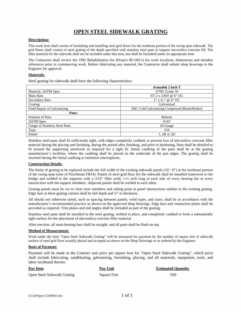
OPEN STEEL SIDEWALK GRATING
Description:
This work item shall consist of furnishing and installing steel grid floors for the northeast portion of the swing span sidewalk. The grid floors shall consist of steel grating of the depth specified with stainless steel pans to support microsilica concrete fill. The filler material for the sidewalk shall not be included under this item, but shall be furnished under its appropriate item.
The Contractor shall review the 1982 Rehabilitation Set (Project 80-100-1) for work locations, dimensions and member references prior to commencing work. Before fabricating any material, the Contractor shall submit shop drawings to the Engineer for approval.
Materials:
Steel grating for sidewalk shall have the following characteristics:
Armadek 2 inch T Material, ASTM Spec. A709, Grade 50 Main Bars ST 2 x 3.85# @ 6” OC Secondary Bars 1” x ¼ “ @ 4” OC Coating Galvanized Field Repair of Galvanizing ZRC Cold Galvanizing Compound (Brush/Roller)
Pans: Position of Pans Bottom ASTM Spec. A167 Gauge of Stainless Steel Pans 20 Gauge Type 316 Finish 1, 2B or 2D
Stainless steel pans shall fit sufficiently tight, with edges completely caulked, to prevent loss of microsilica concrete filler material during the placing and finishing, during the period after finishing, and prior to hardening. Pans shall be detailed to fit around the supporting steelwork as required for a tight fit. Initial caulking of the pans shall be at the grating manufacturer’s facilities, where the caulking shall be placed on the underside of the pan edges. The grating shall be inverted during the initial caulking to minimize interruptions.
Construction Details:
The limits of grating to be replaced include the full width of the existing sidewalk panels (10’- 0”) at the northeast portion of the swing span (east of Floorbeam FB14). Panels of steel grid floor for the sidewalk shall be installed transverse to the bridge and welded to the supports with a 3/16" fillet weld, 1-½ inch long at each side of every bearing bar at every intersection with the support members. Adjacent panels shall be welded to each other.
Grating panels must be cut to clear truss members and railing posts at panel intersections similar to the existing grating. Edge bars at these grating cutouts shall be full depth and ¼” in thickness.
All details not otherwise noted, such as spacing between panels, weld types, and sizes, shall be in accordance with the manufacturer’s recommended practice as shown on the approved shop drawings. Edge bars and connection plates shall be provided as required. Trim plates and end angles shall be included as part of the grating.
Stainless steel pans shall be installed in the steel grating, welded in place, and completely caulked to form a substantially tight surface for the placement of microsilica concrete filler material.
After erection, all main bearing bars shall be straight, and all parts shall be flush on top.
Method of Measurement:
Work under the item “Open Steel Sidewalk Grating” will be measured for payment by the number of square feet of sidewalk surface of steel grid floor actually placed and accepted as shown on the Shop Drawings or as ordered by the Engineer.
Basis of Payment:
Payment will be made at the Contract unit price per square foot for “Open Steel Sidewalk Grating”, which price shall include fabricating, sandblasting, galvanizing, furnishing, placing, and all materials, equipment, tools, and labor incidental thereto.
Pay Item Pay Unit Estimated Quantity
Open Steel Sidewalk Grating Square Feet 950
I/2128/Spec/2128S001.doc 1 of 1
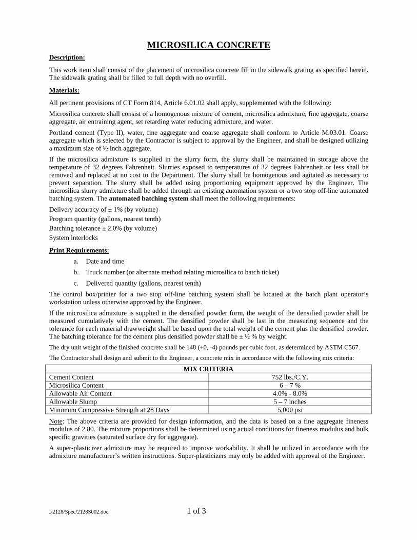
MICROSILICA CONCRETE
Description:
This work item shall consist of the placement of microsilica concrete fill in the sidewalk grating as specified herein. The sidewalk grating shall be filled to full depth with no overfill.
Materials:
All pertinent provisions of CT Form 814, Article 6.01.02 shall apply, supplemented with the following:
Microsilica concrete shall consist of a homogenous mixture of cement, microsilica admixture, fine aggregate, coarse aggregate, air entraining agent, set retarding water reducing admixture, and water.
Portland cement (Type II), water, fine aggregate and coarse aggregate shall conform to Article M.03.01. Coarse aggregate which is selected by the Contractor is subject to approval by the Engineer, and shall be designed utilizing a maximum size of ½ inch aggregate.
If the microsilica admixture is supplied in the slurry form, the slurry shall be maintained in storage above the temperature of 32 degrees Fahrenheit. Slurries exposed to temperatures of 32 degrees Fahrenheit or less shall be removed and replaced at no cost to the Department. The slurry shall be homogenous and agitated as necessary to prevent separation. The slurry shall be added using proportioning equipment approved by the Engineer. The microsilica slurry admixture shall be added through an existing automation system or a two stop off-line automated batching system. The automated batching system shall meet the following requirements:
Delivery accuracy of ± 1% (by volume)
Program quantity (gallons, nearest tenth)
Batching tolerance ± 2.0% (by volume)
System interlocks
Print Requirements:
a. Date and time
b. Truck number (or alternate method relating microsilica to batch ticket)
c. Delivered quantity (gallons, nearest tenth)
The control box/printer for a two stop off-line batching system shall be located at the batch plant operator’s workstation unless otherwise approved by the Engineer.
If the microsilica admixture is supplied in the densified powder form, the weight of the densified powder shall be measured cumulatively with the cement. The densified powder shall be last in the measuring sequence and the tolerance for each material drawweight shall be based upon the total weight of the cement plus the densified powder. The batching tolerance for the cement plus densified powder shall be ± ½ % by weight.
The dry unit weight of the finished concrete shall be 148 (+0, -4) pounds per cubic foot, as determined by ASTM C567.
The Contractor shall design and submit to the Engineer, a concrete mix in accordance with the following mix criteria:
MIX CRITERIA Cement Content 752 lbs./C.Y. Microsilica Content 6 – 7 % Allowable Air Content 4.0% - 8.0% Allowable Slump 5 – 7 inches Minimum Compressive Strength at 28 Days 5,000 psi
Note: The above criteria are provided for design information, and the data is based on a fine aggregate fineness modulus of 2.80. The mixture proportions shall be determined using actual conditions for fineness modulus and bulk specific gravities (saturated surface dry for aggregate).
A super-plasticizer admixture may be required to improve workability. It shall be utilized in accordance with the admixture manufacturer’s written instructions. Super-plasticizers may only be added with approval of the Engineer.
I/2128/Spec/2128S002.doc 1 of 3
Construction Methods:
All the pertinent requirements of CT Form 814, Article 6.01.03 shall apply supplemented with the following:
Equipment: The Contractor shall utilize a central mix plant to batch the microsilica concrete.
Technical Representative: The Contractor shall provide the services of a representative of the microsilica manufacturer. This Representative shall be experienced in the use of microsilica concrete and shall be approved by the Engineer. The Representative shall provide advice on the mixing, placement, and curing of the microsilica grating fill. The Representative is to be present prior to placing operations to inspect the prepared surface and during the first day of placement operations.
Schedule of Equipment and Operations: At least thirty (30) days before the commencing of these operations, the Contractor shall submit procedures to demonstrate compliance with ACI 306 “Standard Practice for Cold Weather Concreting”, and ACI 305 “Hot Weather Concreting”, in accordance with Article 1.05.02 for review by the Engineer. This information shall include details of equipment to be used in placing and finishing of the concrete, including the number and type of personnel who will be engaged in placing the concrete. The personnel shall consist exclusively of persons with skill and experience appropriate to their working assignments.
Mixing, Placing and Finishing: No microsilica concrete shall be placed when the ambient air or steel grating surface temperature is lower than 45 degrees Fahrenheit. No microsilica concrete shall be placed when the air or steel grating surface is greater than 80 degrees Fahrenheit or when it is forecast that the ambient temperature will exceed 80 degrees Fahrenheit within 4 hours from the beginning of the proposed placement time, unless the Contractor demonstrates to the Engineer’s satisfaction that the evaporation rate is less than 0.15 lbs. per square foot per hour and will not exceed this rate within 4 hours from the beginning of the grating fill placement. Plastic concrete temperature shall be between 60 and 80 degrees Fahrenheit.
The Contractor shall satisfy the Engineer that all necessary finishing tools, equipment, and manpower are on hand at the site of work, and that experienced finishers will be employed to finish the microsilica concrete surface. Placing microsilica concrete shall conform to the pertinent requirements of Subarticles 6.01.03-09 and 12.
Placement in the gratings shall be continuous, stopping only at the joints. Placement for the sidewalk shall be struck flush with the top of the grating. No overfill is permitted for sidewalk.
The microsilica concrete discharged from the mixer shall be uniform in composition and consistency. It shall be placed to approximately ¼ inch above grade and then screeded with approved finishing equipment. The microsilica shall be broom (or brush) finished. Hand finishing with wood floats may be required along the edge of the placement.
Placement and finishing equipment shall satisfy the following requirements:
Hand tools may be used for placement and brushing-in of and for distributing the microsilica concrete fill to correct level for screeding. Hand operated vibrators and screeds may be used to place and finish small areas of work.
A bulkhead shall be installed in case of a major delay (greater than 1 hour) in the placement operations. During minor delays, the placement shall be protected from drying with several layers of wet burlap.
Adequate precautions shall be taken to protect freshly placed concrete from sudden or unexpected rain. The Engineer may order the removal and replacement of any material damaged by rainfall, at the Contractor’s expense.
Test Cylinders: Department personnel shall cast cylinders for 4, 7, and 28-day comprehensive strength tests. If the Contractor prefers additional cylinders, a request must be made to the
Engineer. The Contractor must provide adequate curing conditions by both methods as follows:
a) Curing box, and b) cured in the field under the same conditions as the filled bridge deck grating.
Test Blocks: Three test blocks shall be cast and cured and adequately weighed within one week prior to placement. Deviation from the specified unit weight may require revisions to balance calculations. Placement of the concrete will not be permitted until a comparison between the actual unit weight and the specified unit weight has been completed and any necessary adjustment to ensure span balance has been made. Three additional test blocks shall be made during the actual placement of the concrete.
During placing and finishing the evaporation rate shall not exceed 0.1 pound per square foot per hour of exposed concrete as determined by ACI 305R-5, Fig. 2.1.5. Possible procedures to control evaporation may include cooling ingredients prior to mixing, use of temporary windbreaks, sun shades, light fog misting above the concrete, and/or these combined with other measures directed by the Engineer.
I/2128/Spec/2128S002.doc 2 of 3
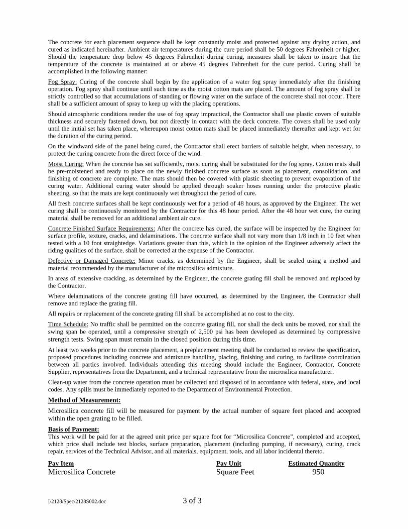
The concrete for each placement sequence shall be kept constantly moist and protected against any drying action, and cured as indicated hereinafter. Ambient air temperatures during the cure period shall be 50 degrees Fahrenheit or higher. Should the temperature drop below 45 degrees Fahrenheit during curing, measures shall be taken to insure that the temperature of the concrete is maintained at or above 45 degrees Fahrenheit for the cure period. Curing shall be accomplished in the following manner:
Fog Spray: Curing of the concrete shall begin by the application of a water fog spray immediately after the finishing operation. Fog spray shall continue until such time as the moist cotton mats are placed. The amount of fog spray shall be strictly controlled so that accumulations of standing or flowing water on the surface of the concrete shall not occur. There shall be a sufficient amount of spray to keep up with the placing operations.
Should atmospheric conditions render the use of fog spray impractical, the Contractor shall use plastic covers of suitable thickness and securely fastened down, but not directly in contact with the deck concrete. The covers shall be used only until the initial set has taken place, whereupon moist cotton mats shall be placed immediately thereafter and kept wet for the duration of the curing period.
On the windward side of the panel being cured, the Contractor shall erect barriers of suitable height, when necessary, to protect the curing concrete from the direct force of the wind.
Moist Curing: When the concrete has set sufficiently, moist curing shall be substituted for the fog spray. Cotton mats shall be pre-moistened and ready to place on the newly finished concrete surface as soon as placement, consolidation, and finishing of concrete are complete. The mats should then be covered with plastic sheeting to prevent evaporation of the curing water. Additional curing water should be applied through soaker hoses running under the protective plastic sheeting, so that the mats are kept continuously wet throughout the period of cure.
All fresh concrete surfaces shall be kept continuously wet for a period of 48 hours, as approved by the Engineer. The wet curing shall be continuously monitored by the Contractor for this 48 hour period. After the 48 hour wet cure, the curing material shall be removed for an additional ambient air cure.
Concrete Finished Surface Requirements: After the concrete has cured, the surface will be inspected by the Engineer for surface profile, texture, cracks, and delaminations. The concrete surface shall not vary more than 1/8 inch in 10 feet when tested with a 10 foot straightedge. Variations greater than this, which in the opinion of the Engineer adversely affect the riding qualities of the surface, shall be corrected at the expense of the Contractor.
Defective or Damaged Concrete: Minor cracks, as determined by the Engineer, shall be sealed using a method and material recommended by the manufacturer of the microsilica admixture.
In areas of extensive cracking, as determined by the Engineer, the concrete grating fill shall be removed and replaced by the Contractor.
Where delaminations of the concrete grating fill have occurred, as determined by the Engineer, the Contractor shall remove and replace the grating fill.
All repairs or replacement of the concrete grating fill shall be accomplished at no cost to the city.
Time Schedule: No traffic shall be permitted on the concrete grating fill, nor shall the deck units be moved, nor shall the swing span be operated, until a compressive strength of 2,500 psi has been developed as determined by compressive strength tests. Swing span must remain in the closed position during this time.
At least two weeks prior to the concrete placement, a preplacement meeting shall be conducted to review the specification, proposed procedures including concrete and admixture handling, placing, finishing and curing, to facilitate coordination between all parties involved. Individuals attending this meeting should include the Engineer, Contractor, Concrete Supplier, representatives from the Department, and a technical representative from the microsilica manufacturer.
Clean-up water from the concrete operation must be collected and disposed of in accordance with federal, state, and local codes. Any spills must be immediately reported to the Department of Environmental Protection.
Method of Measurement:
Microsilica concrete fill will be measured for payment by the actual number of square feet placed and accepted within the open grating to be filled.
Basis of Payment:This work will be paid for at the agreed unit price per square foot for “Microsilica Concrete”, completed and accepted, which price shall include test blocks, surface preparation, placement (including pumping, if necessary), curing, crack repair, services of the Technical Advisor, and all materials, equipment, tools, and all labor incidental thereto.
Pay Item Pay Unit Estimated Quantity Microsilica Concrete Square Feet 950
I/2128/Spec/2128S002.doc 3 of 3
REMOVAL OF EXISTING SIDEWALK GRATING Description:
This work item shall consist of the removal and disposal of approximately 95 linear feet of concrete filled steel grating panels. The north east portion of the swing span sidewalk grating is to be removed in preparation for an in-kind replacement. The limits of grating to be removed include the full width of the existing sidewalk panels (10’-0”) at the eastern half of the north sidewalk of the swing span (east of Floorbeam FB14).
The Contractor shall review the 1982 Rehabilitation Set (Project 80-100-1) for work locations, dimensions and member references prior to commencing work. The Contractor shall also examine the structure prior to commencing work in order to make his own determination of the work and conditions to be encountered.
Construction Details:
Prior to the removal of any materials, the Contractor shall erect barricades as required to protect the public by closure of the north sidewalk during this construction work. Any resulting deck openings shall be covered at the end of any workday. Also, if existing deck panels are removed but not immediately replaced with new panels, then the swing span must be temporarily balanced in preparation for any bridge opening.
The Engineer must approve the method of sidewalk panel removal and disposal prior to the Contractor commencing work. All debris shall be promptly cleaned up and removed from the site. Any material that falls into the river as a result of this removal operation shall be reported to the Engineer and then removed from the riverbed by the Contractor immediately. Care shall be taken to assure that the removal operation does not result in any damage to the existing superstructure and railing members.
The existing sidewalk panels are attached with a fillet weld between the main bearing bars and the support members below. See the 1982 Rehabilitation Set (Project 80-100-1) for details and dimensions.
After each existing sidewalk panel is removed, the panel shall be accurately weighed. The weights for each panel shall be recorded and its location documented on a sketch. Upon completion of work, copies of these records shall be turned over to the engineer.
Once the existing sidewalk panels are removed, the Contractor shall grind any excess weld material off the top of the existing sidewalk stringers and other supporting members prior to paint preparation. The resulting exposed portion of the top flange of the support members shall be painted with an organic zinc rich paint. Color and paint system to be compatible with the existing paint system. Method of Measurement: Payment under this item shall be on a lump sum basis and will not be measured for payment. This item includes the complete removal and disposal of the designated sidewalk grating panels from the site along with any required temporary deck opening closures and span balance work to be performed during this construction work. Basis of Payment: Payment will be made at the Contract lump sum price for “Removal of Existing Sidewalk Grating”, which price shall include all materials, equipment, tools and labor incidental thereto. The materials, equipment, tools and labor required for any temporary deck closure work and temporary balance work is also to be included as a part of this lump sum pay item. Pay Item Pay Unit Estimated Quantity Removal of Existing Sidewalk Grating Lump Sum LS
I/2128/Spec/2128S003.doc 1 of 1
SECTION 21.01 TREE REMOVAL
21.01.1 DESCRIPTION This work shall consist of the removal of trees including stumps, roots and branches from the project site. 21.01.2 NOT APPLICABLE 21.01.3 CONSTRUCTION METHODS All trees which are to be removed shall be cut off not less than 12 inches from the existing surface and removed from the project site. Stumps and roots shall be completely dug up and removed from the project site. In no case will burning of removed trees including stumps and roots be allowed. Excavations or holes created by stump and root removal shall be backfilled with acceptable material to conform to the surrounding ground surface. 21.01.4 METHOD OF MEASUREMENT The quantity of tree removal will not be measured for payment. 21.01.5 BASIS OF PAYMENT Tree removal will not be paid for at the contract unit price, per tree, for "Tree Removal (6" dia. to 24" dia.)" and for "Tree Removal (over 24" dia.)", it shall be included in the payment for clearing and grubbing.
21.01-1
SECTION 21.04 REMOVAL OF CONCRETE
21.04.1 DESCRIPTION Concrete Removal shall consist of the satisfactory removal of concrete designated on the plans to be completely or partly removed, except concrete removed which falls within the limits of "Unclassified Excavation." It shall include concrete, reinforcing and bases as required by the contract or as directed by the Engineer. 21.04.2 MATERIALS NOT APPLICABLE 21.04.3 CONSTRUCTION METHODS Concrete shall be cut to neat lines with a concrete saw as required by the Contract Drawings, or as directed by the Engineer. Concrete shall be excavated to the dimension shown on the plan. Concrete shall be disposed of as directed by the Engineer and in the same manner as described for "Surplus Excavated Material" in the Special Conditions of these specifications. No sections or pieces of concrete shall be used in trench backfill and concrete shall be kept separate from other excavated material. 21.04.4 METHOD OF MEASUREMENT No measurement will be made for the "Concrete Removal". 21.04.5 BASIS OF PAYMENT No separate payment will be made for "Removal of Concrete" it shall be included in the payment for "Clearing and Grubbing". 21.04-1
1115224 21.04-1
SECTION 02800 AUTOMATIC IRRIGATION SYSTEM PART 1 GENERAL SPECIFICATIONS 1.01 PURPOSE A. The objective of these specifications is to provide an assembled and fully functioning automatic irrigation system, which will efficiently irrigate all areas to be covered and shall be acceptable in all aspects to the Owner. These specifications, design details, and irrigation plans are to be considered part of the Contract, and the Contractor shall follow the specifications with due perseverance. 1.02 SCOPE OF WORK A. The work is located on the property of New Haven, CT. Conform to the State Standards regarding special conditions, materials of construction and technical specifications. Where conflicts with these specifications occur, the more stringent shall apply. B. The work contemplated by these specifications consists of the Contractor furnishing all materials, labor, equipment, and services required for all work described herein to install a fully automatic sprinkler system. This includes, but is not limited to all permits, bonds, codes, and State Licensure where applicable. C. Unless otherwise specified, the plan and specifications are intended to include everything necessary for proper installation and completion of the work whether each necessary item is mentioned herein or not. The plan and specifications are intended to be cooperative and any item called for in one and not the other shall be as if called for in both. If a discrepancy exists between the plans and the specifications, the plan takes precedence. D. All work specified shall be executed in compliance with all governing ordinances, laws and regulations of the State or any other authority having jurisdiction over the work. Additionally, any changes and/or additions in the work necessary to meet these conditions will be made without additional cost to the Owner. E. The work to be done under this Contract includes, but is not limited to the following: 1. Furnish and install new piping, fittings, isolation valves and necessary pipe line appurtenances. 2. Provide water tap from city street main with backflow prevention. Coordinate work with the owner. 3. Provide one fall winterization blow-out of the system and one spring start-up. 1.03 TIME OF COMPLETION A. Delays caused by the Owner, the Owner's representative, others who are not party to the Contractor, but whose act or action must precede work performed under this Contract, Acts of God, organized labor disputes and fire are considered legitimate delays to the time of completion. A reasonable extension for the completion date shall be mutually agreed upon, in writing, by the Owner and Contractor. 1.04 SITE INSPECTION A. Each bidder must visit the site of the proposed work and fully acquaint itself with the conditions there relating to construction and labor involving the Contract. Bidder shall thoroughly examine any form or legal document regarding the contract or site visit. 1.05 OWNER'S AUTHORIZED REPRESENTATIVE (S)
IRRIGATION SYSTEM 2800-1
A. The only authority to approve work, estimates, or the final contract is the Owner or his authorized representative(s). The Owner shall notify the Contractor in writing if he designated an authorized representative(s). For the scope of these plan and specifications, the term "Owner" refers to the Owner or his authorized representative(s). 1.06 UTILITIES AND PROTECTION A. The Owner shall make available to the Contractor all necessary information regarding the known locations of existing utilities or drainage line within the site's property lines. Before beginning any work, Contractor shall mark locations of such utilities and/or any underground obstructions at the site. Also, Contractor shall call a Dig Safe service before beginning any work. The Contractor shall be fully liable for the damages to and the cost of repairing or replacing any utilities encountered during the installation of the work, unless it was not previously informed of such underground utilities. If a utility is damaged that the Owner did not make the Contractor aware of, the Owner shall be liable for the cost. 1.07 SUBLETTING OF THE CONTRACT A. The Contractor shall not assign or sublet in whole or any part of this work without obtaining the prior written consent of the Owner approving the specific party to whom it is proposed to sublet the same. 1.08 INSURANCE - LIABILITY, WORKMANS COMPENSATION & SOCIAL SECURITY A. The Contractor shall protect the Owner against all liabilities, claims, or demands for injuries or damages to any person or property under this Contract. The Contractor shall assume all liability for any injuries or damages occasioned by its agents or employees acting within the scope of work on the premises of the Owner. The Contractor shall protect the owner against all claims arising from the use of passenger automobiles, motor trucks, and other motor vehicles owned and operated by Contractor and/or its employees in connection with the work herein specified. B. The Contractor shall accept the provisions of Workmen's Compensation Act of the State and shall procure Workmen's Compensation Insurance covering all until the work covered by these plans and specifications has been fully completed. The Contractor shall file with the Owner certificate of insurance complying with the provisions of this paragraph, prior to the commencement of any work. C. The Contractor shall pay the contributions measured by the Wages of its employees and the employees of its Sub-Contractors required by the Social Security Act and/or the public Laws of the State and assume exclusive liability for said contributions. The Contractor shall further agree to hold harmless the Owner on account of any contributions measured by the wages above stated, of employees of its and its Sub-Contractors, assessed against the Owner under the authority of said Act and the Public Laws of the State. 1.09 WAGE LAWS A. While working on the premises of the Owner, Contractor agrees to comply with all requirements of the Wage and Hour Act and shall be held responsible for compliance. 1.10 HANDLING OF CONTRACTOR'S MATERIAL AND EQUIPMENT A. A Contractor shall provide and pay for all transportation required to deliver and remove from the site all materials and equipment, as required for all the work shown and specified. 1.11 EQUIPMENT, TOOLS AND LABOR
IRRIGATION SYSTEM 2800-2
A. The Contractor shall furnish all such equipment, materials, tools, and labor necessary to pursue the work in an acceptable manner, towards rapid completion. This Contract is based on the Contractor furnishing equipment, materials, tools, and labor which are suitable to carry out this contract in a professional and thorough manner, unless otherwise herein specified. 1.12 OWNER'S SUPERVISION A. The Owner assumes no responsibility in the supervision and inspection of the work involved in the execution of this Contract beyond insuring, to the Owner's satisfaction, that the plan, general conditions, and specifications are being properly interpreted and implemented. This supervision and inspection will not relieve the Contractor of any responsibility for the performance of its work in accordance with the plan, general conditions, and specifications. 1.13 CHANGES IN THE WORK A. The Owner shall have the right to require alterations and deductions from, the work shown on the drawing or described in the specifications without rendering void the contract. All such changes shall be in the form of a change order prepared by the Contractor. Contractor will compute the value of the work and submit in proposal form, but will not proceed with the changes until signed authorization has been given by the Owner. In each case the price agreed to be paid for the work under the Contract shall be increased or decreased for the work added or omitted. In the event the value of the work or cost adjustment furnished by the Contractor is unacceptable to the Owner, the Contract shall be performed without reference to said change order. 1.14 TERMINATION OF CONTRACT A. If the Contractor refuses or fails to execute the work with such diligence as will insure its completion within the time specified in these Contract Documents, the Owner, by written notice to the Contractor, may terminate the Contractor's right to proceed with the work. 1.15 QUALIFICATION OF BIDDERS A. The bidder shall submit with its bid a list of three (3) previously completed projects of a similar nature to this project. The Owner reserves the right to request additional data information necessary to qualify the Bidder. The Owner reserves the right to reject any bid, if in the opinion of the Owner, the Contractor is not qualified. A list of previous references and telephone numbers and who may be contacted shall also be included. PART 2 MATERIAL SPECIFICATIONS 2.01 MATERIALS A. The materials chosen for the design of the sprinkler system have been specifically referred to by the manufacturer so as to enable the Owner to establish the level of quality and performance required by the system design. In order to maintain this quality, all heads, electric valves, and controllers are to be manufactured by a single manufacturer. Equipment by other manufacturers other than what is specified may be considered (provided that the heads, valves, and controllers are made by a single manufacturer) only after written application, at least seven days prior to the bid opening, including six copies of product specification sheets, is made by the bidder, and written approval is received from the Owner. B. The major components of the irrigation system shall be covered by a two year over-the-counter warranty C. Submittals: 1) Material list:
IRRIGATION SYSTEM 2800-3
a.) Complete material list shall be submitted prior to performing any work. Material list shall include the manufacturer's model number and description of all materials and equipment to be used. Materials installed or furnished and not matching submitted material list shall be rejected by the Owner and shall require the Contractor to remove such equipment or materials from the site at its own expense. b.) Manufacturer's warranties shall not relieve the Contractor of its liabilities and responsibilities under these specifications. 2) Equipment to be furnished at conclusion of the project: a.) One (1) quick-coupler key. Before final acceptance of the work, Contractor shall provide written evidence that the Owner has received these materials. 2.02 DRIPPERLINE The drip tubing shall be a pre-bonded emitter type. The tubing shall have emitters spaced at 12 inches and in flow rates of 1.0 gallons per hour (GPH) with a coefficient of variance (Cv) of .05. Water distribution shall be via an integrated turbulent flow path emitter with dual discharge ports on opposing sides of the tubing. The tubing shall consist of nominal-sized linear, low-density 5/8” polyethylene with an outside diameter (O.D.) of approximately .710 inches and an inside diameter (I.D.) of approximately .620 inches. The emmitters shall be molded from virgin polyethylene impregnated with TREFLAN to inhibit root intrusion. Further, the emitters shall be manufactured under one of more of the following ROOTGUARD patent numbers: USA: 5116414; U.K.: 2174884. The tubing shall be available in pressure-compensating and non-pressure-compensating types. The pressure compensating type shall incorporate a circular silicon rubber disk designed to flush at startup, shutdown and during the irrigation cycle to inhibit debris collection. The drip tubing shall be a model number RGP-412-03 and shall be provided by The Toro Company, Irrigation Division, Riverside, California. FILTER The filter shall be a “Y” body type with inlet and outlet threads of ¾” inch (MIPT). The filter shall incorporate a stainless-steel screen providing a mesh of 150, a filtration area of 23.4 square inches and be capable of providing a flow rate ranging from 4 to 11 gallons per minute (GPM). The “Y” filter body shall be a two-piece threaded type molded from glass-reinforced, corrosive-proof engineering thermoplastics. The body shall be capable of being serviced by unthreading the two pieces and shall incorporate a rubber O-ring seal. The “Y” filter body shall also incorporate a ¾” MHT outlet to provide for periodic flushing of the filter. The filter screen shall be made of woven stainless steel attached to a vinyl screen collar. The filter shall be a model number AP4E-75 and shall be provided by The Toro Company, Irrigation Division, Riverside, California. PRESSURE REGULATOR The regulator shall be a preset type with inlet and outlet threads of ¾” FIPT capable of maintaining an outlet pressure of 40 pounds per square inch (PSI) with a regulation accuracy of +/- 6% and a maximum pressure rating of 150 PSI, while providing flow rates ranging from 2- 20 gallons per minute (GPM). The regulator shall be constructed of high-impact, corrosive-proof engineering thermoplastics. Pressure regulation shall be accomplished by a fixed, stainless-steel compression spring enclosed in a chamber separate from the normal water passage. The pressure regulator shall provide negligible flow restriction until factory-preset pressure regulation is achieved. The regulator shall be a model number PMR40-MF and shall be provided by The Toro Company, Irrigation Division, Riverside, California. FLUSHING CAP
IRRIGATION SYSTEM 2800-4
The flushing cap shall be a preset type with a compression inlet capable of accepting .710-inch O.D. plastic drip tubing. The flushing cap body shall be a two-piece, threaded type constructed of corrosive-proof engineering thermoplastics. The body shall be capable of being serviced by unthreading the two pieces, and shall incorporate a molded synthetic rubber seal. The flushing cap seat shall be constructed of a molded synthetic rubber held in the open position by a stainless-steel spring. The flushing cap shall be capable of flushing 0.8 GPM at system startup and shall seal at 10 PSI. The flushing cap shall be a model number CEFCH-H and shall be provided by The Toro Company, Irrigation Division, Riverside, California. 2.06 BRONZE IPS BALL VALVE The bronze ips ball valve shall the following features: - Constructed with screwed ends. - The body and end retainer shall be made from #85-5-5-5 bronze, ASTM B62. - The handle nut and lever handle shall be made from zinc plated steel, ASTM A-107. - Packing nut and stem shall be made of Brass, ASTM B-16. - Stem packing, thrust washer, and seats shall be made from Teflon, PTFE. - The ball shall be made of Chrome Plated Brass. - Working non-shock pressure of 150 psi for saturated steam, and 200 psi for cold water, oil and gas. - The body shall have a hydrostatic test pressure of 300 psi and the seat shall be 200 psi. B. The ball valve shall be as manufactured by Aqua Valve Company, Orinda, CA. The valve boxes shall have the following features: - Valve boxes shall be constructed of rigid combination of polyolefin and fibrous components especially compounded for under-ground enclosures. - Superflexion plastic material shall be chemically insert and normally unaffected by moisture, corrosion, and the effects of temperature changes. - Superflexion shall also have a relatively high tensile strength with light weight because of its solid structural material. - Each valve box shall include a locking cover which shall have a slightly mottled, grass-like green color that will blend into the turf. - Valve boxes shall be available in the following configurations: Round - 10"x13"x10 1/4" deep, Standard - top: 10 3/4"x16", bottom: 10 3/4"x18 1/2" and 12" deep; Jumbo - top; 14 3/4" x 21 1/2" bottom: 17 1/4"x24" and 12" deep. - The contractor shall fill the entire area beneath the box with pea gravel before final installation of each box. B. The valve box shall be as manufactured by Brooks Industries, Glendale, CA. 2.08 BACKFLOW PREVENTER The backflow preventer shall the following features: - Reduced Pressure Device consisting of two (2) independently operating, spring loaded, "Y" pattern check valves and one (1) hydraulically dependent differential relief valve. - The device shall automatically reduce the pressure in the zone between the check valves to at least five PSI lower than the inlet pressure. - Should the differential between the upstream and the zone of the unit drop to two psi, the relief valve shall open and maintain the proper differential. - Mainline and valve body and caps, including relief valves shall be bronze. - Check valve moving member shall be center stem guided. - All hydraulic sensing passages shall be internally located within the mainline and relief valve bodies and relief valve cover. - Check and relief valve components shall be constructed so they may be serviced without removal. - Shut-off valves shall be fully ported. - The device shall be rated to 175 PSI water working pressure and water temperature range from 32 to 140 degrees F. B. The backflow preventer shall be an 825Y series as manufactured by Febco Sales, Fresno, CA. 2.09 ENCLOSURE The enclosure shall have the following features: - Made of 14 gauge steel. - The outside shall be painted grey with a baked on enamel. - Access to the box shall be via the hinged door. - The bottom shall be enclosed. - The dimensions of the box shall be H- 36" x W- 30" x D -16".
IRRIGATION SYSTEM 2800-5
B. The enclosure shall be as manufactured by McKinstry, Inc., Chicopee, MA PART 3 EXECUTION SPECIFICATIONS 3.01 INSTALLATION REQUIREMENTS A. The word "piping” in this specification means pipe, fittings, nipples, and valves, and shall be considered as such in this installation. B. The drawing indicates the areas to be served by the sprinkler system. The sprinkler system shall be installed coordinated with the landscape needs and that any further changes or additions needed to water the indicated areas shall be included as part of the Contract without additional charges unless agreed upon by the Owner. Install pipes as shown on the Drawing, and directed during the installation as straight and direct as possible. The locations of the valves, sprinklers, controllers, water taps, backflow assemblies, pipes, wires, and related items shall be accurately laid out in the field by the Contractor. The design shall be considered a guide and shall be field adjusted without compromising it’s integrity. Coordinating the installation with other trades rests with the Contractor. Should it be found that any work is laid out so that interference will occur, report that to the Owner before commencing work. 3.02 EXCAVATING AND BACKFILLING A. The Contractor shall do all necessary excavating and backfilling required for the proper installation of the work excepting as noted on the plan. B. When backfilling, all backfill material shall be free from rock, large stone or other unsuitable substances to prevent damage to the pipe and all common control wiring. Backfilling of trenches containing plastic pipe shall be done when the pipe is cool to avoid excessive contraction in cold weather. All backfill material will be compacted in 6" layers as it's brought up to finish grade so as to insure that no settling results. 3.03 PIPE INSTALLATION A. The Contractor must provide effective protection at all times to prevent sand, rubbish, or any other debris from entering the piping. When work is stopped at night, or at any other time, the ends of the pips must be closed with plugs properly secured. Sidewalks shall be clear of project debris and equipment at all times and barricades and/or tape shall be installed around any trenches left open. PVC piping 2 inches and smaller shall be trenched to a depth of 12 to 18 inches as soil and grade conditions permit. B. PVC sleeves shall be installed with 12” of cover minimum. Locate in the field. C. Any cutting or breaking of sidewalks and/or concrete necessary shall be performed by the Contractor and paving replaced as part of the Contract cost. Permission to cut or break sidewalks and/or concrete shall be obtained from the Owner. No hydraulic driving or drilling will be permitted under asphaltic concrete paving. 3.04 CLEANING THE PREMISES A. Clean up shall be performed as each portion of the work progresses. Refuse, rubbish and excess dirt shall be removed from the site. Upon completion of the job, the Contractor shall clean up all debris caused by its work and leave the job in a neat and clean condition. All sidewalks and paving shall be washed down. All debris removed from the job will be taken away from the premises. 3.05 ROCK EXCAVATION A. If rock is encountered in the alignment and depth shown on the plan the alignment and/or depth shall be adjusted in order to avoid its excavation if at all possible. If alignment and depth adjustment cannot be made and it becomes necessary to remove the same, the Contractor shall be paid for all the additional cost incurred in the handling of it per submitted rock clause bid.
IRRIGATION SYSTEM 2800-6
3.06 TESTING THE SYSTEM A. Work included under this section includes all tests required under laws, ordinances, rules and regulation of the State of Connecticut or any other authority having jurisdiction over the work, and shall be made in accordance therewith to prove watertightness of both systems. B. Both systems shall be tested by the Contractor for a minimum time limit of two (2) hours at the normal system hydrostatic pressure and upon visual inspection of the ground, should any leak be found, it shall be promptly repaired. The line shall then be re-tested until proven watertight. C. The work under this section shall include the furnishing of all testing instruments, gauges, pumps, etc., and other equipment with appurtenances required or necessary for all test. D. Owner shall be notified at least forty-eight (48) hours in advance of all tests and all tests shall be conducted to Owner's full satisfaction. 3.07 TRENCH SETTLEMENT A. Contractor, as part of the work under this Contract, shall make adjustments without extra cost to the Owner, if within one year from completion date, major settlement to this system occurs. These settlements include, but are not limited to: improper compaction, an adjustment in pipe or sprinkler heads, topsoil or paving settlement, or related items. 3.08 ADJUSTING AND BALANCING THE SYSTEMS A. Contractor shall adjust all sprinkler heads and valves for optimum performance and to prevent, as much as possible, any over-spray onto walks, stairs, and roadways. No spray is permitted on buildings. Such adjustments shall include adjusting or changing nozzle sizes, installing and replacing pressure compensating devices (PCD's) of sprinkler heads, and changing degrees of arc of sprinklers. B. Following all tests for watertightness and integrity, and following the above adjustments, Contractor shall perform complete coverage tests of both systems in presence of the Owner to confirm adequate and complete coverages to Owner's full satisfaction. 3.09 AS-BUILT DRAWING A. Within sixty (60) days after completion of the piping installation, Contractor shall furnish an "as-built" drawing showing all sprinkler heads, valves, drains, and pipelines to scale with dimensions where required. Instruction sheets, parts sheets, and manufacturer's manuals covering all equipment and materials will be bound into a single hard cover three ring binder and furnished to the Owner. 3.10 INSTRUCTIONS A. After completion and testing of the system, Contractor shall instruct Owner's personnel in the proper and full operation and maintenance of the systems. Confirmation of such instruction shall be furnished in writing at conclusion of the project. 3.11 SERVICE AND GUARANTEE A. The Contractor shall submit a single guarantee that all portions of the work are in accordance with the Contract requirements and providing for maintenance of the system. The Contractor shall guarantee all work against faulty and improper material and workmanship for a period of one (1) year from date of final acceptance by the Owner, except that where guarantees or warranties for longer terms are specified herein, such longer term to apply. Within forty-eight (48) hours after notification, Contractor shall correct any deficiencies which occur during the guarantee period at no additional
IRRIGATION SYSTEM 2800-7
cost to the Owner, all to the satisfaction of the Owner. The Contractor shall also obtain similar guarantees from its Subcontractors. B. The Contractor shall be responsible for all leaks in all pipes for a period of one (1) year from date of acceptance of work under this Contract. Repair at no cost to the Owner all such leaks which occur within forty-eight (48) hours prior to the completion of this Contract at once. The Contractor shall be responsible for any damage caused by such leaks and repair. C. The Contractor shall provide all service necessary to maintain the system for a period of one (1) year from date final acceptance from the Owner. This shall include properly winterizing the system in the Winter and starting the system in Spring. Part 4 METHOD OF MEASUREMENT This work will not be measured for payment. Part 5 BASIS OF PAYMENT Payment for this work will be made at the contract unit price for “Irrigation System” complete in place, which price shall include all materials, equipment, tools and labor necessary to complete the work. END OF SECTION
IRRIGATION SYSTEM 2800-8


![U.S. Department of Labor Management... · U.S. Department of Labor Occupational Safety & Health Administration MyOSHA [skip navigational links] Search Advanced Search | A-Z Index](https://img.pdfslide.net/doc/110x75/5fc0bfa2a9069b660d3be96b/us-department-of-labor-management-us-department-of-labor-occupational-safety.jpg)


![BLAST [Basic Alignment Local Search Tool]](https://img.pdfslide.net/doc/110x75/54bd24c14a7959ae068b45b7/blast-basic-alignment-local-search-tool.jpg)