Embed Size (px)
Citation preview
SETUP MANUAL

All rights reserved. No part of this publication may be reproduced, stored in a retrieval system, or transmitted, in any form, or by any means, mechanical, electronic, photocopying, recording, or otherwise, without the prior written permission of OMRON.
No patent liability is assumed with respect to the use of the information contained herein. Moreover, because OMRON is constantly striving to improve its high-quality products, the information contained in this manual is subject to change without notice. Every precaution has been taken in the preparation of this manual. Neverthe-less, OMRON assumes no responsibility for errors or omissions. Neither is any liability assumed for damages resulting from the use of the information contained in this publication.
• Sysmac and SYSMAC are trademarks or registered trademarks of OMRON Corporation in Japan and other countries for OMRON factory automation products.
• Microsoft, Windows, Windows Vista, and Excel are either registered trademarks or trademarks of Microsoft Corporation in the United States and other countries.
• EtherCAT® is registered trademark and patented technology, licensed by Beckhoff Automation GmbH, Germany.
• ODVA, CIP, CompoNet, DeviceNet, and EtherNet/IP are trademarks of ODVA.
• The SD and SDHC logos are trademarks of SD-3C, LLC.
Other company names and product names in this document are the trademarks or registered trademarks of their respective companies.
Trademarks
Copyrights
NOTE
Microsoft product screen shots reprinted with permission from Microsoft Corporation.
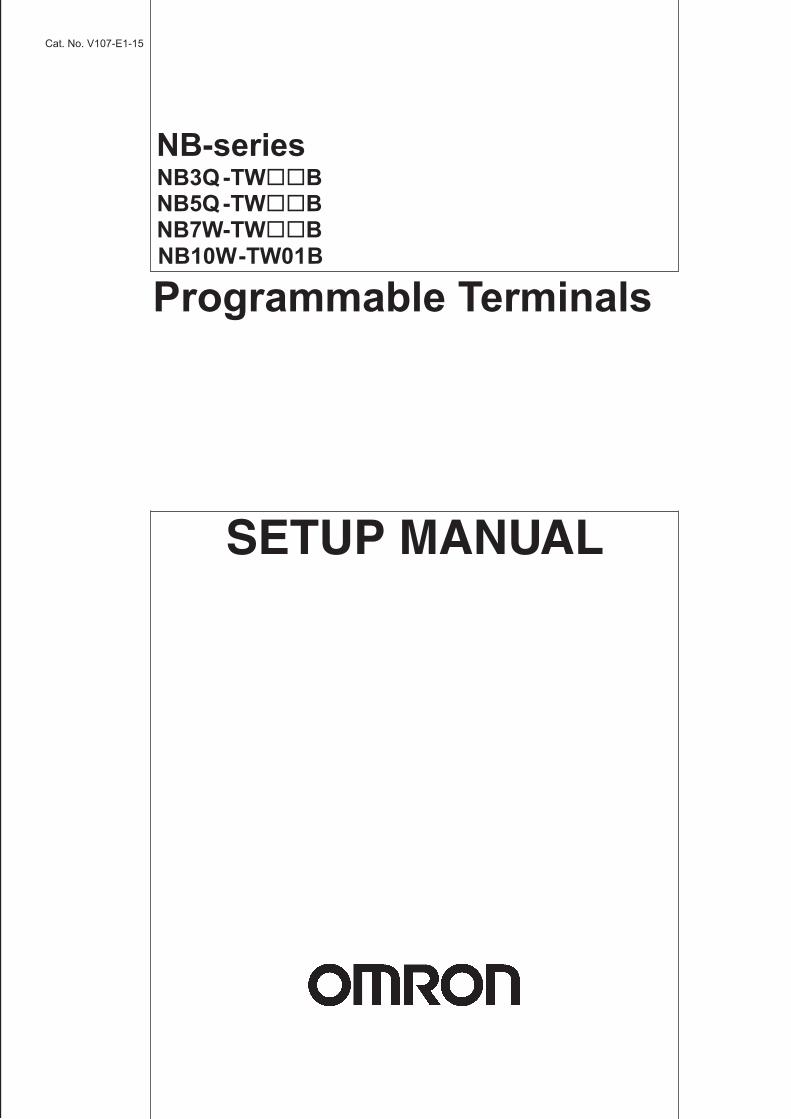
NB-seriesNB3Q-TWBNB5Q-TWBNB7W-TWBNB10W-TW01BProgrammable TerminalsSetup ManualRevised October 2018

1NB-series Programmable Terminals Setup Manual(V107)
Introduction
Thank you for purchasing an NB-series Programmable Terminal.
NB-Series Programmable Terminals (PTs) are designed to handle information generated in FA production sites. Be sure to understand the functions and performances etc thoroughly before using PT correctly.
This manual is intended for the following personnel, who must also have knowledge of electrical systems (an electrical engineer or the equivalent).
• Personnel in charge of introducing FA systems into production facilities.
• Personnel in charge of designing FA systems.
• Personnel in charge of installing and connecting FA facilities.
• Personnel in charge of managing FA systems and facilities
• The user must operate the product according to the performance specifications described in the operation manuals.
• Do not use the PT touch switch input functions for applications where danger to human life or serious property damage is possible, or for emergency switch applications.
• Before using the product under conditions which are not described in the manual or applying the product to nuclear control systems, railroad systems, aviation systems, vehicles, combustion systems, medical equipment, amusement machines, safety equipment, and other systems, machines and equipment that may have a serious influence on lives and property if used improperly, consult your OMRON representative.
• Make sure that the ratings and performance characteristics of the product are sufficient for the systems, machines, and equipment, and be sure to provide the systems, machines, and equipment with double safety mechanisms.
• This manual provides information for connecting and setting up an NB-Series PT. Be sure to read this manual before attempting to use the PT and keep this manual close at hand for reference during installation and operation.
Intended Audience
General Precautions
2 NB-series Programmable Terminals Setup Manual(V107)
NB-series Manuals
NB-series manuals are organized in the sections listed in the following tables. Refer to the appropriatesection in the manuals as required.
Programmable Terminals Setup Manual (Cat. No. V107)(This Manual)
Section Contents
Section 1 Part Names and Functions This section describes the names and functions of the various parts of an NB Unit.
Section 2 Installing the NB Unit and Connecting Peripheral Devices
This section describes the methods used to install the NB Unit and connect peripheral devices.
Section 3 System Setting Mode This section describes the System Setting Mode.
Section 4 Calibrate Mode This section describes the Calibrate Mode.
Appendices The appendices provide information on specifications, dimensions, wirings, and lists of the NB Units, the applicable PLCs and options.
Programmable Terminals NB-Designer Operation Manual (Cat. No. V106)
Section Contents
Section 1 Introduction This section provides an outline of the NB-series PTs, including their functions, features, connection types and communication methods.
Section 2 Installation and Startup of NB-Designer
This section describes how to install and start the NB-Designer.
Section 3 Functions of NB-Designer This section describes the functions of NB-Designer.
Section 4 Functions of NBManager This section describes the functions of NBManager.
Section 5 Maintenance and Abnormality Handling
This section describes the maintenance and check to prevent the abnormality occurrence and the handling of the abnormalities occurred in NB Unit.
Section 6 Functions Related to External Memory
This section describes the functions related to external memory.
Section 7 Pictbridge Printing This section describes the Pictbridge printing function.
Section 8 Web Interface This section describes the Web Interface function.
Appendices The appendices provide lists of the NB Units, the Communication Units, the applicable PLCs, the registers supported by PLC, and the list of NB-Designer functions.
3NB-series Programmable Terminals Setup Manual(V107)
Programmable Terminals Host Connection Manual (Cat. No. V108)Section Contents
Section 1 List for All PLCs Supported by NB series
This section lists all PLCs supported by NB Units.
Section 2 Connecting to SIEMENS PLCs
This section describes the connection to SIEMENS PLCs.
Section 3 Connecting to Mitsubishi PLCs
This section describes the connection to Mitsubishi PLCs.
Section 4 Connecting to Schneider PLCs
This section describes the connection to Schneider PLCs.
Section 5 Modbus Connection This section describes the connection on Modbus protocol.
Section 6 Connecting to Delta PLCs This section describes the connection to Delta PLCs.
Section 7 Connecting to LSIS PLCs This section describes the connection to LSIS PLCs.
Section 8 Connecting to Panasonic Industrial Devices SUNX PLCs
This section describes the connection to Panasonic Industrial Devices SUNX PLCs.
Section 9 Connecting to Allen-Bradley (Rockwell) PLC
This section describes the connection to Allen-Bradley PLC.
Section 10 Connecting to PLC of GE Fanuc Automation Inc.
This section describes the connection to PLC of GE Fanuc Automation Inc.
Section 11 Connecting to Keyence PLCs
This section describes the connection to Keyence PLCs.
Section 12 Connecting to OMRON Safety Controller
This section describes the connection to OMRON Safety Controller.
Programmable Terminals Startup Guide Manual (Cat. No. V109)Section Contents
Section 1 NB Overview This section provide specifications of the NB Unit, describes its names and functions of the various parts.
Section 2 System Design This section describes the manual structure, takes NB7W as an example to introduce the operation procedures of the NB system.
Section 3 Installation and Wiring This section describes how to install and wire the NB Unit.
Section 4 Screen Creation This section describes how to create a demonstration project through NB-Designer.
Section 5 Run This section describes how to start running at the Host side and prepare to send screen data to NB7W.
Section 6 Maintenance and Troubleshooting
This section describes the maintenance and inspection methods for preventing errors occurring, and troubleshooting measures when errors occur.
WARNING
Failure to read and understand the information provided in this manual may result in personal injury or death, damage to the product, or product failure.Please read each section in its entirety and be sure you understand the information provided in the section and related sections before attempting any of the procedures or operations given.
4 NB-series Programmable Terminals Setup Manual(V107)
Manual Structure
The following page structure and icons are used in this manual.
Special information in this manual is classified as follows:
Page Structure and Icons
Special Information
2-3
2 Installing the NB Unit and Connecting Peripheral Devices
NB-series Programmable Terminals Setup Manual(V107)
2-1 Installin
g th
e NB
Un
it
2
2-1-2 Installation onto the Operation P
anel
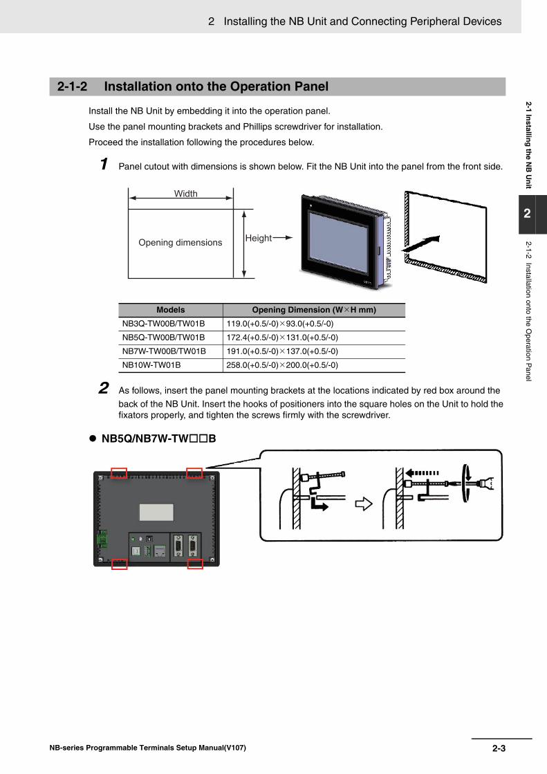
Install the NB Unit by embedding it into the operation panel.
Use the metal kit and tool (a crosshead screwdriver) supplied with the Unit for installation.
Proceed the installation following the procedures below.
1 Panel cutout with dimensions is shown below. Fit the NB Unit into the panel from the front side.
2 As follows, insert panel fixators at the locations indicated by red box around the back of the NB Unit.
Insert the hooks of positioners into the square holes on the Unit to hold the fixators properly, and tighten the screws firmly with the screwdriver.
NB5Q/NB7W-TW��B
Precautions for Safe Use
• When operating on the operation panel, make sure to keep metal particles from entering the Unit.
The mounting panel must be between 1.6 and 4.8 mm thick. The NB Unit must be installed in a control panel.
For the sake of waterproof and dustproof, all the fixators must be evenly tightened to a torque of 0.5~0.6 Nm. If the tightening torque exceeds the specified value, or the tightening is not even, deformation of the front panel may occur.
Make sure that the operation panel is clean, unbent, and strong enough for the installation process.
2-1-2 Installation onto the Operation Panel
Models Opening Dimension (W H mm)
NB3Q-TW00B/TW01B 119.0(+0.5/-0) 93.0(+0.5/-0)
NB5Q-TW00B/TW01B 172.4(+0.5/-0) 131.0(+0.5/-0)
NB7W-TW00B/TW01B 191.0(+0.5/-0) 137.0(+0.5/-0)
NB10W-TW01B 258.0(+0.5/-0) 200.0(+0.5/-0)
Opening dimensions
Width
Height
Level 1 headingLevel 2 headingLevel 3 heading
Step in a procedure
Manual name
Special Information (See below.)
Level 3 heading
Page tab
Gives the current headings.
Indicates a step in a procedure.
Gives the number of the section.
This illustration is provided only as a sample and may not literally appear in this manual.
Icons are used to indicate precautions and additional information.
Precautions for Safe UsePrecautions on what to do and what not to do to ensure using the product safely.
Precautions for Correct UsePrecautions on what to do and what not to do to ensure proper operation and performance.
Additional InformationAdditional information to increase understanding or make operation easier.

5NB-series Programmable Terminals Setup Manual(V107)
Terminology
The following terminology is used in this manual.
Terms Descriptions
NB Unit Indicates the main Unit of the products in the OMRON NB Series of Programmable Terminal.
NB Series Indicates products in the OMRON NB Series of Programmable Terminal.In this manual, unless otherwise specified, NB Series is taken as the subject concerned.
PLC Indicates a Programmable Controller.
CP Series Indicates the following products in the OMRON CP Series of Programmable Controllers: CP1H, CP1L, CP1E
CS/CJ Series Indicates the following products in the OMRON CS/CJ Series of Programmable Controllers: CS1G, CS1H, CS1G-H, CS1H-H, CJ1G, CJ1M, CJ2M, CJ2H
NJ/NX Series Indicates the following OMRON SYSMAC NJ/NX Series of Programmable Controllers: NJ501, NJ301, NJ101, NX102, NX1P2
C Series Indicates the following products in the OMRON C Series of Programmable Controllers: C200HX(-Z), C200HG(-Z), C200HE(-Z), CQM1, CQM1H, CPM1A, CPM2A, CPM2C
Serial Communication Unit
Indicates a Serial Communication Unit for an OMRON SYSMAC CS/CJ-Series PLC.
Serial Communication Board
Indicates a Serial Communication Board for an OMRON SYSMAC CS/CJ-Series PLC.
Communication Board Indicates a Communication Board for an OMRON C200HX/HG/HE(-Z) PLC.
CPU Unit Indicates a CPU Unit in the OMRON CP, CS/CJ or SYSMAC C Series of Programmable Controllers.
NB-Designer Indicates the OMRON NB-Designer.
Host Indicates the PLC and other units functioning as the control devices for NB-Series Units.
PT Indicates an OMRON Programmable Terminal.

6 NB-series Programmable Terminals Setup Manual(V107)
7NB-series Programmable Terminals Setup Manual(V107)
CONTENTS
Introduction............................................................................................................... 1
NB-series Manuals.................................................................................................... 2
Manual Structure ...................................................................................................... 4
Terminology .............................................................................................................. 5
Terms and Conditions Agreement .......................................................................... 9
Safety Precautions ................................................................................................. 11
Precautions for Safe Use ....................................................................................... 14
Precautions for Correct Use .................................................................................. 16
Conformance to EC Directives .............................................................................. 17
Related Manuals ..................................................................................................... 18
Sec. 1 Part Names and Functions.................................................... 1-1
1-1 Part Names............................................................................................................................... 1-2
1-2 Part Specifications .................................................................................................................. 1-6
Sec. 2 Installing the NB Unit and Connecting Peripheral Devices2-1
2-1 Installing the NB Unit .............................................................................................................. 2-22-1-1 Installation environment.............................................................................................................. 2-22-1-2 Installation onto the Operation Panel.......................................................................................... 2-32-1-3 Connecting the Power Supply..................................................................................................... 2-52-1-4 Grounding Wiring........................................................................................................................ 2-6
2-2 Start of NB Series .................................................................................................................... 2-7
2-3 Connecting of NB-series with PC .......................................................................................... 2-82-3-1 Connecting by RS-232C ............................................................................................................. 2-82-3-2 Connecting by USB .................................................................................................................... 2-92-3-3 Connecting by Ethernet ............................................................................................................ 2-10
2-4 Serial Communication Connection...................................................................................... 2-112-4-1 Host Link Connection Method................................................................................................... 2-112-4-2 Connecting more than one PLC ............................................................................................... 2-122-4-3 Settings for each Unit ............................................................................................................... 2-13
2-5 UDP Communication Connection ........................................................................................ 2-272-5-1 Connecting to Host Via Ethernet .............................................................................................. 2-272-5-2 Parameter Settings for UDP at NB Side ................................................................................... 2-302-5-3 Host Types and Settings of Ethernet Unit ................................................................................. 2-322-5-4 Host Types and Settings of Ethernet/IP Unit ............................................................................ 2-382-5-5 Parameter Settings at Host Side (CX-Programmer) ................................................................. 2-432-5-6 Parameter Settings at Host Side (Sysmac Studio) ................................................................... 2-44
8 NB-series Programmable Terminals Setup Manual(V107)
Sec. 3 System Setting Mode............................................................. 3-1
3-1 Display Method of System Setting Mode .............................................................................. 3-2
3-2 Functions of System Setting Mode........................................................................................ 3-3
Sec. 4 Calibrate Mode ....................................................................... 4-1
4-1 Display Method of Calibrate Mode......................................................................................... 4-2
4-2 Functions of Calibrate Mode .................................................................................................. 4-2
4-3 On-line Touch-control Calibration Function ......................................................................... 4-2
Sec. A Appendices.............................................................................A-1
A-1 Specifications .........................................................................................................................A-2A-1-1 General Specifications ................................................................................................................A-2A-1-2 Performance Specifications.........................................................................................................A-2A-1-3 Communication Specifications ....................................................................................................A-4
A-2 External Dimensions ...............................................................................................................A-5
A-3 RS-422A/485 Connections ......................................................................................................A-7A-3-1 Grounding and Shielding of the Cables ......................................................................................A-7
A-4 Fabrication of the Connection Cable .....................................................................................A-9A-4-1 Cable Processing ........................................................................................................................A-9A-4-2 Soldering...................................................................................................................................A-10A-4-3 Shield Assembly........................................................................................................................A-10A-4-4 Method for Fabricating the Cable for Connection to OMRON PLC ...........................................A-11A-4-5 Method for fabricating the cable for connection to PC ..............................................................A-14
A-5 List of Models ........................................................................................................................A-15
A-6 List of Options .......................................................................................................................A-19
Revision History........................................................................................................1
9NB-series Programmable Terminals Setup Manual(V107)
Terms and Conditions Agreement
Exclusive WarrantyOmron’s exclusive warranty is that the Products will be free from defects in materials and workman-ship for a period of twelve months from the date of sale by Omron (or such other period expressed inwriting by Omron). Omron disclaims all other warranties, express or implied.
LimitationsOMRON MAKES NO WARRANTY OR REPRESENTATION, EXPRESS OR IMPLIED, ABOUTNON-INFRINGEMENT, MERCHANTABILITY OR FITNESS FOR A PARTICULAR PURPOSE OFTHE PRODUCTS. BUYER ACKNOWLEDGES THAT IT ALONE HAS DETERMINED THAT THEPRODUCTS WILL SUITABLY MEET THE REQUIREMENTS OF THEIR INTENDED USE.
Omron further disclaims all warranties and responsibility of any type for claims or expenses basedon infringement by the Products or otherwise of any intellectual property right.
Buyer Remedy
Omron’s sole obligation hereunder shall be, at Omron’s election, to (i) replace (in the form originallyshipped with Buyer responsible for labor charges for removal or replacement thereof) the non-com-plying Product, (ii) repair the non-complying Product, or (iii) repay or credit Buyer an amount equalto the purchase price of the non-complying Product; provided that in no event shall Omron beresponsible for warranty, repair, indemnity or any other claims or expenses regarding the Productsunless Omron’s analysis confirms that the Products were properly handled, stored, installed andmaintained and not subject to contamination, abuse, misuse or inappropriate modification. Return ofany Products by Buyer must be approved in writing by Omron before shipment. Omron Companiesshall not be liable for the suitability or unsuitability or the results from the use of Products in combi-nation with any electrical or electronic components, circuits, system assemblies or any other materi-als or substances or environments. Any advice, recommendations or information given orally or inwriting, are not to be construed as an amendment or addition to the above warranty.
See http://www.omron.com/global/ or contact your Omron representative for published information.
OMRON COMPANIES SHALL NOT BE LIABLE FOR SPECIAL, INDIRECT, INCIDENTAL, ORCONSEQUENTIAL DAMAGES, LOSS OF PROFITS OR PRODUCTION OR COMMERCIAL LOSSIN ANY WAY CONNECTED WITH THE PRODUCTS, WHETHER SUCH CLAIM IS BASED INCONTRACT, WARRANTY, NEGLIGENCE OR STRICT LIABILITY.
Further, in no event shall liability of Omron Companies exceed the individual price of the Product onwhich liability is asserted.
Warranty, Limitations of Liability
Warranties
Limitation on Liability; Etc
10 NB-series Programmable Terminals Setup Manual(V107)
Omron Companies shall not be responsible for conformity with any standards, codes or regulationswhich apply to the combination of the Product in the Buyer's application or use of the Product. AtBuyer's request, Omron will provide applicable third party certification documents identifying ratingsand limitations of use which apply to the Product. This information by itself is not sufficient for a com-plete determination of the suitability of the Product in combination with the end product, machine,system, or other application or use. Buyer shall be solely responsible for determining appropriate-ness of the particular Product with respect to Buyer's application, product or system. Buyer shalltake application responsibility in all cases.
NEVER USE THE PRODUCT FOR AN APPLICATION INVOLVING SERIOUS RISK TO LIFE ORPROPERTY OR IN LARGE QUANTITIES WITHOUT ENSURING THAT THE SYSTEM AS AWHOLE HAS BEEN DESIGNED TO ADDRESS THE RISKS, AND THAT THE OMRON PROD-UCT(S) IS PROPERLY RATED AND INSTALLED FOR THE INTENDED USE WITHIN THE OVER-ALL EQUIPMENT OR SYSTEM.
Omron Companies shall not be responsible for the user's programming of a programmable Product,or any consequence thereof.
Data presented in Omron Company websites, catalogs and other materials is provided as a guidefor the user in determining suitability and does not constitute a warranty. It may represent the resultof Omron's test conditions, and the user must correlate it to actual application requirements. Actualperformance is subject to the Omron's Warranty and Limitations of Liability.
Product specifications and accessories may be changed at any time based on improvements andother reasons. It is our practice to change part numbers when published ratings or features arechanged, or when significant construction changes are made. However, some specifications of theProduct may be changed without any notice. When in doubt, special part numbers may be assignedto fix or establish key specifications for your application. Please consult with your Omron's represen-tative at any time to confirm actual specifications of purchased Product.
Information presented by Omron Companies has been checked and is believed to be accurate; how-ever, no responsibility is assumed for clerical, typographical or proofreading errors or omissions.
Suitability of Use
Programmable Products
Disclaimers
Performance Data
Change in Specifications
Errors and Omissions
11NB-series Programmable Terminals Setup Manual(V107)
Safety Precautions
The following notation is used in this manual to provide precautions required to ensure safe usage of the product. The safety precautions that are provided are extremely important to safety. Always read and heed the information provided in all safety precautions.
Notation Used for Safety Information
Symbols
• ProhibitionIndicates a general prohibition.
• CautionIndicates general cautionary, warning, or danger level information.
WARNINGIndicates an imminently hazardous situation which, if not avoided, will result in death or serious injury. Additionally, there may be severe property damage.
Precautions for Safe UseIndicates precautions on what to do and what not to do to ensure using the product safely.
Precautions for Correct UseIndicates precautions on what to do and what not to do to ensure proper operation and performance.
Note Indicates suggestive information and precautions on operation of the product.
12 NB-series Programmable Terminals Setup Manual(V107)
Do not attempt to take the product apart and do not touch the product inside while the power is being supplied. Otherwise it may result in electric shock.
Always ensure that the personnel in charge confirm that installation, inspection, and maintenance were properly performed for the NB Unit.
“Personnel in charge” refers to individuals qualified and responsible for ensuring safety during machine design, installation, operation, maintenance, and disposal.
Ensure that installation and post-installation checks are performed by personnel in charge who possess a thorough understanding of the machinery to be installed.
Do not use the input functions of the touch switch, etc. of the NB Unit, in applications that involve human life, in applications that may result in serious injury, or for emergency stop switches.
Do not attempt to disassemble, repair, or modify the NB Unit. Otherwise it may impair the safety functions.
Never press at two or more points on the touch panel of the NB Unit at a time. Otherwise, it may activate a switch somewhere between the two points.
WARNING
13NB-series Programmable Terminals Setup Manual(V107)
Precaution
Wiring
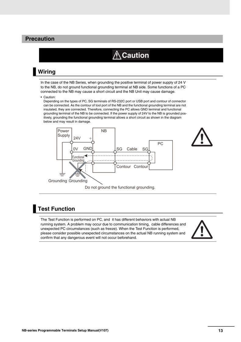
In the case of the NB Series, when grounding the positive terminal of power supply of 24 V to the NB, do not ground functional grounding terminal at NB side. Some functions of a PC connected to the NB may cause a short circuit and the NB Unit may cause damage.
• Caution:Depending on the types of PC, SG terminals of RS-232C port or USB port and contour of connector can be connected. As the contour of tool port of the NB and the functional grounding terminal are not insulated, they are connected. Therefore, connecting the PC allows GND terminal and functional grounding terminal of the NB to be connected. If the power supply of 24V to the NB is grounded pos-itively, grounding the functional grounding terminal allows a short circuit as shown in the diagram below and may result in damage.
Test Function
The Test Function is performed on PC, and it has different behaviors with actual NB running system. A problem may occur due to communication timing, cable differences and unexpected PC circumstances (such as freeze). When the Test Function is performed, please consider possible unexpected circumstances on the actual NB running system and confirm that any dangerous event will not occur beforehand.
Caution
NB
SGSG
24V
0V GND
Power Supply
Grounding Grounding
Functional Grounding
Cable
Contour Contour
PC
Do not ground the functional grounding.

14 NB-series Programmable Terminals Setup Manual(V107)
Precautions for Safe Use
• When unpacking the NB Units and the peripheral devices, check carefully for any external scratches or other damages. Also, shake the Units gently and check for any abnormal sound.
• The NB Unit must be installed in a control panel.
• The mounting panel must be between 1.6 and 4.8 mm thick. Tighten the Mounting Brackets evenly to a torque of between 0.5 and 0.6 Nm to maintain water and dust resistance. If the tightening torque exceeds the specified value, or the tightening is not even, deformation of the front panel may occur. What is more, make sure the panel is not dirty or warped and that it is strong enough to hold the Units.
• Do not let metal particles enter the Units when preparing the panel.
• Do not connect an AC power supply to the DC power terminals.
• Use a DC power with a slight voltage fluctuation and reinforced or double insulation, and that will provide a stable output even if the input is momentarily interrupted for 10 ms.Rated Power Supply Voltage: DC 24 V (Allowable range DC 20.4 ~ 27.6 V)
• Do not perform a dielectric voltage test.
• Before connecting the power supply to the NB unit, mount the cable on the terminal block. Make the connection by using terminal screws crimping on a twisted-pair cable with a crimping range of 12~26 AWG, and only 6.5 mm of insulation peel of the cable needs to be peeled off. Tighten the terminal screws at a torque of between 0.3 and 0.5 Nm. Make sure the screws are properly tightened. Do not use the terminal block of NB3Q-TWB for other models. NB3Q-TWB has different pin definitions on the terminal block.
• To prevent malfunctions caused by noise, ground the Unit correctly.
• Do not touch the packaging part of the circuit board with your bare hands. Discharge any static electricity from your body before handling the board.
• When using the No. 6 pin of the serial communication port COM1 connector for a voltage of DC+5V, make sure the supply equipment’s current capacity is below 250mA before using it. The DC+5V voltage output of the NB unit is +5V±5%, and the maximum current is 250mA. (The serial communication port COM1 of NB3Q-TWB is unable to output the current.)
• Turn OFF the power supply before connecting or disconnecting cables.
• Always keep the connector screws firmly tightened after the communication cable is connected.
• Do not pull on the cables or bend the cables beyond their natural limit. Do not place heavy objects on top of the cables or other wiring lines. Doing so may break the cables.
• Confirm the safety of the system before turning ON or OFF the power supply, or pressing the reset button.
• The whole system may stop depending on how the power supply is turned ON or OFF. Turn ON/OFF the power supply according to the specified procedure.
• Reset by pressing the reset button, or restart the power supply, once the DIP switch settings are changed.
• To ensure the system’s safety, make sure to incorporate a program that can confirm the normal functionality of the NB Unit before running the system.
• Start actual system application only after sufficiently checking screen data, macros and the operation of the program at the host side.
• Do not press the touch panel with a force greater than 30 N.
• Do not use hard or pointed objects to operate or scrub the screen, otherwise, the surface of the screen may be damaged.
• Confirm the safety of the system before pressing the touch panel.
• Signals from the touch switches may not be input if the touch switches are pressed consecutively at high speed. Confirm each input before proceeding to the next one.
• Do not accidentally press the touch panel when the backlight is not lit or when the display does not appear. Make sure of the safety of the system before pressing the touch panel.
• To use numeric input functions safely, always make maximum and minimum limit settings.
• Before initializing screen data, confirm that existing data is backed up at the NB-Designer.
15NB-series Programmable Terminals Setup Manual(V107)
• When changing the password with the screen, do not reset or turn OFF the power supply until writing is finished. Failure to save the password may cause the screen to fail to function.
• When using an equipment monitor, confirm the safety of the system before carrying out the following operations:
• Changing monitor data.
• Changing operation mode.
• Forced set/reset.
• Changing the current value or the set value.
• Do not connect a USB connector to any device that is not applicable.
• When connecting the equipment with the USB HOST connector, make sure the supply equipment’s current capacity is below 150mA before using it. The DC+5V voltage output of the NB Unit is +5V±5%, and the maximum current is 150mA.
• Before connecting a USB connector to a device, make sure that the device is free of damage.
• Commercially available and the recommended USB HUBs are different from the general specifications of the NB Unit. The unit may not function well in an environment subject to noise, static electricity. Therefore, when using a USB HUB, employ sufficient noise and static electricity insulation measures, or install it at a site free of noise or static electricity.
• While uploading or downloading screen data or system programs, do not perform the following operations that may corrupt the screen data or the system program:
• Turning OFF the power supply of the NB Unit.
• Pressing the PT’s reset switch.
• Dispose of the Units and batteries according to local ordinances as they apply.
• Do not dispose the product into a fire. Doing so may cause the damage with the battery or electronic components.
• Do not apply an impact with the lithium cell, charge it, dispose it into a fire, or heat it. Doing either of them may cause an ignition or a bursting.
• When exporting products with lithium primary batteries containing perchlorate at 6ppb or above to or delivering them through California, USA, the following precautionary measures have to be publicized.Perchlorate material - applicable through special processing. Refer tohttp://www.dtsc.ca.gov/hazardouswaste/perchlorate. NB-Series products contain lithium primary batteries. When exporting products containing this kind of batteries to or delivering them through California, USA, label all the product packages as well as the appropriate delivery packages.
• Do not use benzene, paint thinner, or other volatile solvents, and do not use chemically treated cloths.
• Do not dispose the Units together with general waste at waste yards. When disposing them, follow the related local ordinances or rules.
• Cannot replace the backlight lamp inside the NB Unit.
• Deterioration over time can cause the touch points to move. Calibrate the touch panel periodically.
• Water resistance will be lost if the front sheet is torn or is peeling off. Do not use the Unit, if the front sheet is torn or is peeling off.
• The rubber packing will deteriorate, shrink, or harden depending on the operating environment. Inspect the rubber packing periodically.
• The communication cables of the COM1 and COM2 connectors are not interchangeable. Confirm the pins of the ports before carrying out communications. (NB3Q-TWB only has COM1.)
• Periodically check the installation conditions in applications where the PT is subject to contact with oil or water.
• Do not perform the following operations during the communication of the USB memory:
• Turning off the power supply of the NB Unit.
• Pressing the Reset button on the NB Unit.
• Removing the USB memory.
• Do not use the USB memory in the environment subject to strong vibration.
16 NB-series Programmable Terminals Setup Manual(V107)
Precautions for Correct Use
• Do not install the unit in any of the following locations:Locations subject to severe changes in temperatureLocations subject to temperatures or humidity outside the range specified in the specificationsLocations subject to condensation as the result of high humidityLocations subject to corrosive or flammable gasesLocations subject to strong shock or vibrationLocations outdoors subject to direct wind and rainLocations subject to strong ultraviolet lightLocations subject to dustLocations subject to direct sunlightLocations subject to splashing oil or chemicals
• Take appropriate and sufficient countermeasures when installing systems in the following locations:Locations subject to static electricity or other forms of noiseLocations subject to strong electric field or magnetic fieldLocations close to power supply linesLocations subject to possible exposure to radioactivity
• Precautions for software:The update, restoration, uninstall and reinstallation of software in running status is prohibited in order to guarantee the correct use of the product.
17NB-series Programmable Terminals Setup Manual(V107)
Conformance to EC Directives
NB-Series Programmable Terminals are EMC compliant.
OMRON products are electronic devices that are incorporated in machines and manufacturing installations. OMRON PTs conform to the related EMC Directives (see note) so that the devices and machines into which they are built can more easily conform to EMC Directives. The actual products have been through inspections and are completely in accordance with EMC directives. However, when they are built into customers’ systems, whether the systems also comply with these Directives is up to the customers for further inspection.
EMC-related performance of OMRON PTs will vary depending on the configuration, wiring, and other conditions of the OMRON equipment or control panel. The customer must, therefore, perform final checks to confirm that the overall machine or device conforms to EMC standards.
Note The applicable EMC (Electromagnetic Compatibility) standards are as follows:EMS (Electromagnetic sensitivity): EN61131-2: 2007EMI (Electromagnetic Interference): EN61131-2: 2007
NB-Series Programmable Terminals are EC compliant. Heed the following precautions in order to ensure that the customer’s overall machine and device conform to EC Directives.
1 The PT must be installed in a control panel.
2 You must use reinforced insulation or double insulation for the DC power supply and the DC
power supply must have minimal voltage fluctuations and provide a stable output even if the power supply input is interrupted for 10 ms.
3 The PTs conform to the standard EN 61131-2, but radiated emission characteristics (10m
regulations) may vary depending on the configuration of the control panel used, other devices connected to the control panel, wiring, and other conditions. You must therefore confirm that the overall machine or equipment complies with EC Directives.
4 This is a Class A product (Product for industry purpose). It may cause radio interference in residential
areas, in which case the user may be required to take adequate measures to reduce interference.
Observe the following precaution if you use NB-series Programmable Terminals in Korea.
Class A Device (Broadcasting Communications Device for Office Use)This device obtained EMC registration for office use (Class A), and it is intended to be used in places other than homes.Sellers and/or users need to take note of this.
Concepts
Conformance to EC Directives
Conformance to KC Standards
18 NB-series Programmable Terminals Setup Manual(V107)
Related Manuals
The related manuals are as follows:
Devices and Software Manual Name Manual No.NB series NB Series NB-Designer Operation Manual V106
NB Series Setup Manual (This manual) V107
NB Series Host Connection Manual V108
NB Series Startup Guide V109
PLC SYSMAC CP Series CP1L CPU Unit Operation Manual W462
SYSMAC CP Series CP1H/L CPU Unit Programming Manual W451
SYSMAC CP Series CP1H CPU Unit Operation Manual W450
SYSMAC CP Series CP1E CPU Unit Hardware USER’S Manual
W479
SYSMAC CP Series CP1E CPU Unit Software USER’S Manual
W480
SYSMAC C200HX/HG/HE(-E/-ZE) Installation Guide W302
SYSMAC C200HX/HG/HE Operation Manual W303
SYSMAC C200HX/HG/HE(-ZE) Operation Manual W322
SYSMAC CPM1A Operation Manual W317
SYSMAC CPM2A Operation Manual W352
SYSMAC CPM1/CPM1A/CPM2A/CPM2C/SRM1(-V2) Programming Manual
W353
SYSMAC CPM2C Operation Manual W356
SYSMAC CS1 Series CS1G/H Operation Manual W339
SYSMAC CS/CJ Series Serial Communications Boards and Serial Communications Units Operation Manual
W336
SYSMAC CJ Series CJ1G/H(-H) CJ1M CJ1G Operation Manual
W393
SYSMAC CS/CJ Series Programming Manual W394
SYSMAC CS/CJ Series INSTRUCTIONS Reference Manual W340
SYSMAC CS/CJ Series Programming Consoles Operation Manual W341
SYSMAC CS/CJ Series Communications Commands Reference Manual
W342
SYSMAC CJ Series CJ2 CPU Unit Hardware USER’S Manual W472
SYSMAC CJ Series CJ2 CPU Unit Software USER’S Manual W473
SYSMAC CS/CJ Series CS1W/CJ1W-ETN21 (100Base-TX) Ethernet Units Operation Manual Construction of Networks
W420
SYSMAC CS/CJ Series CS1W/CJ1W-ETN21 (100Base-TX) Ethernet Units Operation Manual Construction of Applications
W421
SYSMAC CS/CJ Series CS1W/CJ1W-EIP21 (100Base-TX) EtherNet/IPTM Units Operation Manual
W465
SYSMAC CP Series CP1L-EL/EM CPU Unit Operation Manual W516
NJ Series CPU Unit Hardware USER’S Manual W500
NJ/NX Series CPU Unit Software USER’S Manual W501
NJ/NX Series CPU Unit Built-in EtherNet/IPTM Port USER’S Manual W506
NJ/NX Series Troubleshooting Manual W503
NX-Series NX102 CPU Unit Hardware User’s Manual W593
NX-Series NX1P2 CPU Unit Hardware User’s Manual W578
NX-Series NX1P2 CPU Unit Built-in I/O and Option Board User’s Manual
W579
External Tool CX-Programmer Ver.9. Operation Manual W446
Sysmac Studio Version 1 Operation Manual W504
1-1NB-series Programmable Terminals Setup Manual(V107)
1
This section describes the names and functions of the various parts of an NB Unit.
1-1 Part Names . . . . . . . . . . . . . . . . . . . . . . . . . . . . . . . . . . . . . . . . . . . . . . . . . . . 1-2
1-2 Part Specifications . . . . . . . . . . . . . . . . . . . . . . . . . . . . . . . . . . . . . . . . . . . . . 1-6
Part Names and Functions
1 Part Names and Functions
1-2 NB-series Programmable Terminals Setup Manual(V107)
1-1 Part Names
NB3Q-TW00B/NB3Q-TW01B modelFront view
Back view
Precautions for Safe Use
Confirm the safety of the system before turning ON or OFF the power supply, or pressing the reset button.
Power Indicator Display
: NB��-TW01B only
1-3
1 Part Names and Functions
NB-series Programmable Terminals Setup Manual(V107)
1-1 Part N
ames
1
NB5Q-TW00B/NB5Q-TW01B modelFront view
Back view
Precautions for Safe Use
Confirm the safety of the system before turning ON or OFF the power supply, or pressing the reset button.
Power Indicator Display
: NB��-TW01B only
1 Part Names and Functions
1-4 NB-series Programmable Terminals Setup Manual(V107)
NB7W-TW00B/NB7W-TW01B modelFront view
Back view
Precautions for Safe Use
Confirm the safety of the system before turning ON or OFF the power supply, or pressing the reset button.
Power Indicator Display
: NB��-TW01B only
1-5
1 Part Names and Functions
NB-series Programmable Terminals Setup Manual(V107)
1-1 Part N
ames
1
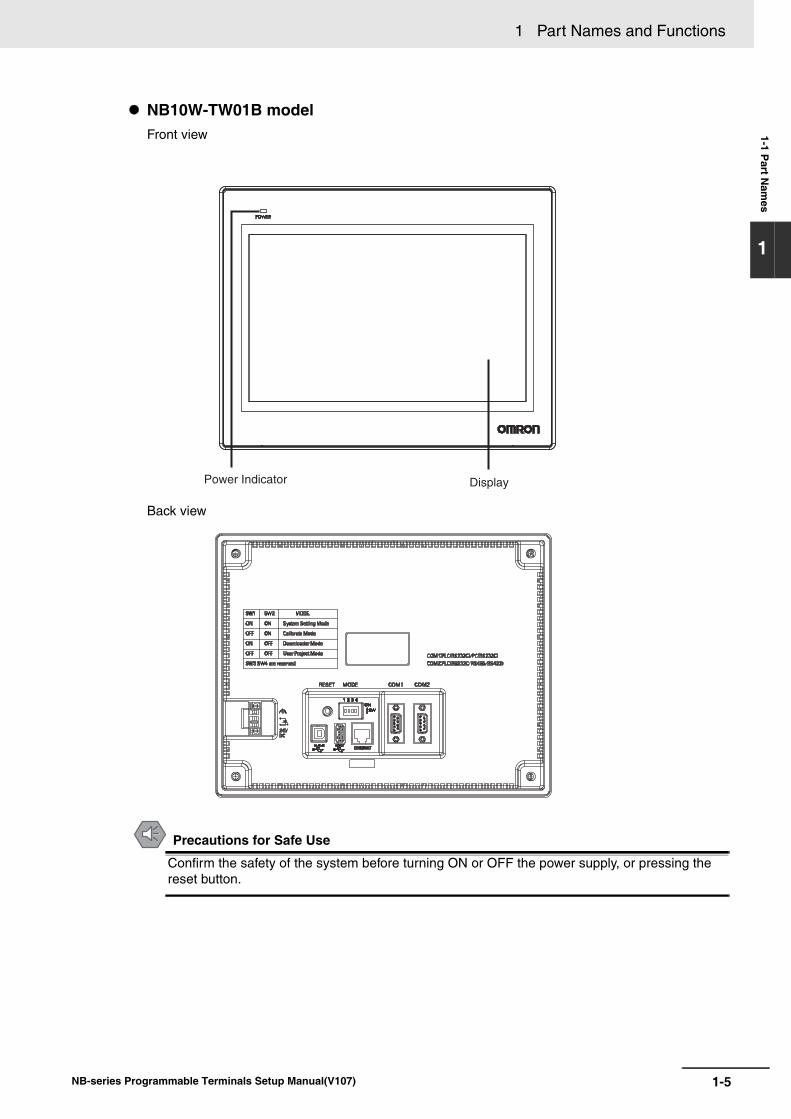
NB10W-TW01B modelFront view
Back view
Precautions for Safe Use
Confirm the safety of the system before turning ON or OFF the power supply, or pressing the reset button.
Power Indicator Display
1 Part Names and Functions
1-6 NB-series Programmable Terminals Setup Manual(V107)
1-2 Part Specifications
Touch PanelInput operation can be carried out by means of the touch panel. By pressing the touch panel, thescreens can be switched, and the contact information can be transmitted to the host. Analog touchpanel with 1024 × 1024 resolution is employed.
Precautions for Safe Use
• Do not press a touch switch with a force greater than 30N.
• Do not accidentally press the touch panel when the backlight is not lit or when the display does not appear. Make sure of the safety of the system before pressing the touch panel.
• Confirm the safety of the system before pressing the touch panel.
• Do not use hard or pointed objects to operate or scrub the screen, or the surface of the screen may be damaged.
• Signals from the touch switches may not be input if the switches are pressed consecutively at high speed. Confirm each input before proceeding to the next one.
• Deterioration over time can cause the touch points to move. If deviation of the touch points stands out, calibrate the touch panel periodically.
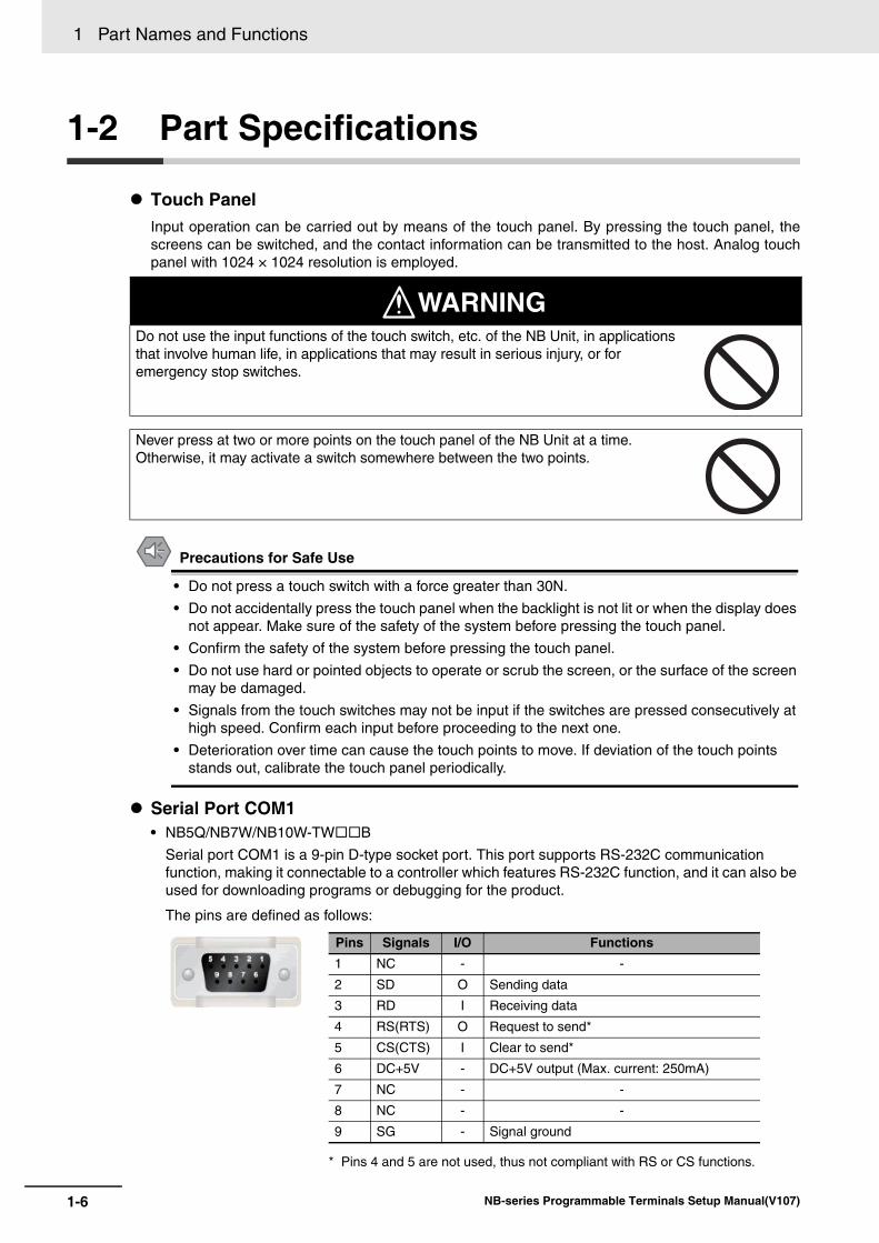
Serial Port COM1• NB5Q/NB7W/NB10W-TWB
Serial port COM1 is a 9-pin D-type socket port. This port supports RS-232C communication function, making it connectable to a controller which features RS-232C function, and it can also be used for downloading programs or debugging for the product.
The pins are defined as follows:
Do not use the input functions of the touch switch, etc. of the NB Unit, in applications that involve human life, in applications that may result in serious injury, or for emergency stop switches.
Never press at two or more points on the touch panel of the NB Unit at a time. Otherwise, it may activate a switch somewhere between the two points.
WARNING
* Pins 4 and 5 are not used, thus not compliant with RS or CS functions.
Pins Signals I/O Functions1 NC - -
2 SD O Sending data
3 RD I Receiving data
4 RS(RTS) O Request to send*
5 CS(CTS) I Clear to send*
6 DC+5V - DC+5V output (Max. current: 250mA)
7 NC - -
8 NC - -
9 SG - Signal ground
1-7
1 Part Names and Functions
NB-series Programmable Terminals Setup Manual(V107)
1-2 Part S
pecifications
1
Precautions for Safe Use
When using the No. 6 pin of the serial communications port COM1 connector for a voltage of DC+5V, make sure the supply equipment’s current capacity is below 250 mA before using it. The DC+5V voltage output of the NB Unit is +5V±5%, and the maximum current is 250 mA.
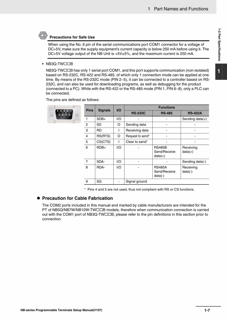
• NB3Q-TWB
NB3Q-TWB has only 1 serial port COM1, and this port supports communication (non-isolated) based on RS-232C, RS-422 and RS-485, of which only 1 connection mode can be applied at one time. By means of the RS-232C mode (PIN 2~5), it can be connected to a controller based on RS-232C, and can also be used for downloading programs, as well as debugging for the product (connected to a PC). While with the RS-422 or the RS-485 mode (PIN 1, PIN 6~8), only a PLC can be connected.
The pins are defined as follows:
Precaution for Cable FabricationThe COM2 ports included in this manual and marked by cable manufacturers are intended for the PT of NB5Q/NB7W/NB10W-TWB models, therefore when communication connection is carried out with the COM1 port of NB3Q-TWB, please refer to the pin definitions in this section prior to connection.
* Pins 4 and 5 are not used, thus not compliant with RS or CS functions.
Pins Signals I/OFunctions
RS-232C RS-485 RS-422A
1 SDB+ I/O - - Sending data(+)
2 SD O Sending data - -
3 RD I Receiving data - -
4 RS(RTS) O Request to send* - -
5 CS(CTS) I Clear to send* - -
6 RDB+ I/O - RS485B Send/Receive data(+)
Receiving data(+)
7 SDA- I/O - - Sending data(-)
8 RDA- I/O - RS485A Send/Receive data(-)
Receiving data(-)
9 SG - Signal ground
1 Part Names and Functions
1-8 NB-series Programmable Terminals Setup Manual(V107)
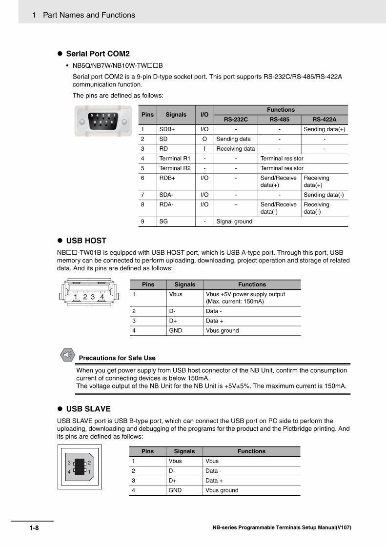
Serial Port COM2• NB5Q/NB7W/NB10W-TWB
Serial port COM2 is a 9-pin D-type socket port. This port supports RS-232C/RS-485/RS-422A communication function.
The pins are defined as follows:
USB HOSTNB-TW01B is equipped with USB HOST port, which is USB A-type port. Through this port, USB memory can be connected to perform uploading, downloading, project operation and storage of related data. And its pins are defined as follows:
Precautions for Safe Use
When you get power supply from USB host connector of the NB Unit, confirm the consumption current of connecting devices is below 150mA.The voltage output of the NB Unit for the NB Unit is +5V±5%. The maximum current is 150mA.
USB SLAVEUSB SLAVE port is USB B-type port, which can connect the USB port on PC side to perform the uploading, downloading and debugging of the programs for the product and the Pictbridge printing. And its pins are defined as follows:
Pins Signals I/OFunctions
RS-232C RS-485 RS-422A
1 SDB+ I/O - - Sending data(+)
2 SD O Sending data - -
3 RD I Receiving data - -
4 Terminal R1 - - Terminal resistor
5 Terminal R2 - - Terminal resistor
6 RDB+ I/O - Send/Receive data(+)
Receiving data(+)
7 SDA- I/O - - Sending data(-)
8 RDA- I/O - Send/Receive data(-)
Receiving data(-)
9 SG - Signal ground
1 2 3 4
Pins Signals Functions
1 Vbus Vbus +5V power supply output(Max. current: 150mA)
2 D- Data -
3 D+ Data +
4 GND Vbus ground
3
4 1
2
Pins Signals Functions
1 Vbus Vbus
2 D- Data -
3 D+ Data +
4 GND Vbus ground
1-9
1 Part Names and Functions
NB-series Programmable Terminals Setup Manual(V107)
1-2 Part S
pecifications
1
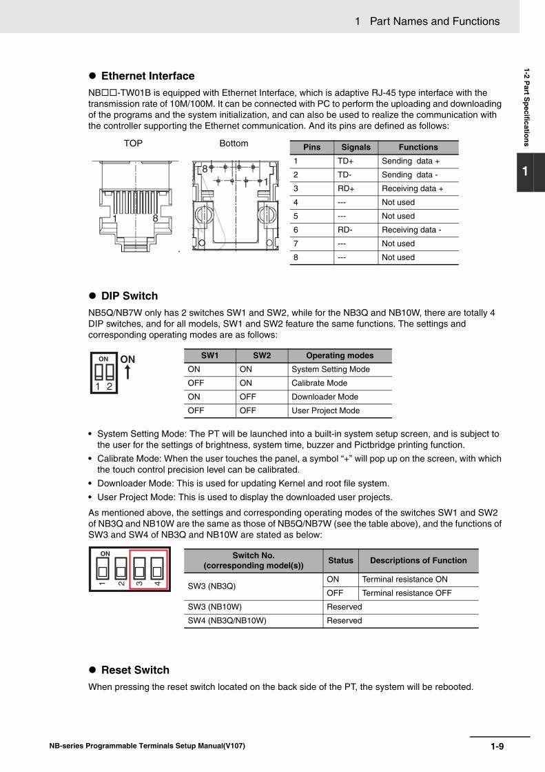
Ethernet Interface NB-TW01B is equipped with Ethernet Interface, which is adaptive RJ-45 type interface with the transmission rate of 10M/100M. It can be connected with PC to perform the uploading and downloading of the programs and the system initialization, and can also be used to realize the communication with the controller supporting the Ethernet communication. And its pins are defined as follows:
DIP SwitchNB5Q/NB7W only has 2 switches SW1 and SW2, while for the NB3Q and NB10W, there are totally 4 DIP switches, and for all models, SW1 and SW2 feature the same functions. The settings and corresponding operating modes are as follows:
• System Setting Mode: The PT will be launched into a built-in system setup screen, and is subject to the user for the settings of brightness, system time, buzzer and Pictbridge printing function.
• Calibrate Mode: When the user touches the panel, a symbol “+” will pop up on the screen, with which the touch control precision level can be calibrated.
• Downloader Mode: This is used for updating Kernel and root file system.
• User Project Mode: This is used to display the downloaded user projects.
As mentioned above, the settings and corresponding operating modes of the switches SW1 and SW2 of NB3Q and NB10W are the same as those of NB5Q/NB7W (see the table above), and the functions of SW3 and SW4 of NB3Q and NB10W are stated as below:
Reset SwitchWhen pressing the reset switch located on the back side of the PT, the system will be rebooted.
1
1
8
8
Pins Signals Functions
1 TD+ Sending data +
2 TD- Sending data -
3 RD+ Receiving data +
4 --- Not used
5 --- Not used
6 RD- Receiving data -
7 --- Not used
8 --- Not used
TOP Bottom
ON ON
1 2
SW1 SW2 Operating modes
ON ON System Setting Mode
OFF ON Calibrate Mode
ON OFF Downloader Mode
OFF OFF User Project Mode
Switch No. (corresponding model(s)) Status Descriptions of Function
SW3 (NB3Q)ON Terminal resistance ON
OFF Terminal resistance OFF
SW3 (NB10W) Reserved
SW4 (NB3Q/NB10W) Reserved
ON
1 2 3 4

1 Part Names and Functions
1-10 NB-series Programmable Terminals Setup Manual(V107)
2-1NB-series Programmable Terminals Setup Manual(V107)
2
This section describes the methods used to install the NB Unit and connect peripheraldevices.
2-1 Installing the NB Unit . . . . . . . . . . . . . . . . . . . . . . . . . . . . . . . . . . . . . . . . . . . 2-22-1-1 Installation environment . . . . . . . . . . . . . . . . . . . . . . . . . . . . . . . . . . . . . . . . . . 2-2
2-1-2 Installation onto the Operation Panel . . . . . . . . . . . . . . . . . . . . . . . . . . . . . . . . 2-3
2-1-3 Connecting the Power Supply . . . . . . . . . . . . . . . . . . . . . . . . . . . . . . . . . . . . . 2-52-1-4 Grounding Wiring . . . . . . . . . . . . . . . . . . . . . . . . . . . . . . . . . . . . . . . . . . . . . . . 2-6
2-2 Start of NB Series . . . . . . . . . . . . . . . . . . . . . . . . . . . . . . . . . . . . . . . . . . . . . . 2-7
2-3 Connecting of NB-series with PC . . . . . . . . . . . . . . . . . . . . . . . . . . . . . . . . . 2-82-3-1 Connecting by RS-232C . . . . . . . . . . . . . . . . . . . . . . . . . . . . . . . . . . . . . . . . . 2-82-3-2 Connecting by USB . . . . . . . . . . . . . . . . . . . . . . . . . . . . . . . . . . . . . . . . . . . . . 2-92-3-3 Connecting by Ethernet . . . . . . . . . . . . . . . . . . . . . . . . . . . . . . . . . . . . . . . . . 2-10
2-4 Serial Communication Connection . . . . . . . . . . . . . . . . . . . . . . . . . . . . . . 2-112-4-1 Host Link Connection Method . . . . . . . . . . . . . . . . . . . . . . . . . . . . . . . . . . . . 2-11
2-4-2 Connecting more than one PLC . . . . . . . . . . . . . . . . . . . . . . . . . . . . . . . . . . 2-12
2-4-3 Settings for each Unit . . . . . . . . . . . . . . . . . . . . . . . . . . . . . . . . . . . . . . . . . . 2-13
2-5 UDP Communication Connection . . . . . . . . . . . . . . . . . . . . . . . . . . . . . . . . 2-272-5-1 Connecting to Host Via Ethernet . . . . . . . . . . . . . . . . . . . . . . . . . . . . . . . . . . 2-272-5-2 Parameter Settings for UDP at NB Side . . . . . . . . . . . . . . . . . . . . . . . . . . . . 2-30
2-5-3 Host Types and Settings of Ethernet Unit . . . . . . . . . . . . . . . . . . . . . . . . . . . 2-32
2-5-4 Host Types and Settings of Ethernet/IP Unit . . . . . . . . . . . . . . . . . . . . . . . . . 2-382-5-5 Parameter Settings at Host Side (CX-Programmer) . . . . . . . . . . . . . . . . . . . 2-432-5-6 Parameter Settings at Host Side (Sysmac Studio) . . . . . . . . . . . . . . . . . . . . 2-44
Installing the NB Unit and Connecting Peripheral Devices
2 Installing the NB Unit and Connecting Peripheral Devices
2-2 NB-series Programmable Terminals Setup Manual(V107)
2-1 Installing the NB Unit
This section describes the methods used to mount the NB Unit onto an operation panel and connect the power supply.
When mounting the NB Unit onto the operation panel, pay attention to the following precautions.
Precautions for Correct UsePrecautions for Correct Use
• Do not install the product in any of the following locations:
Locations subject to rapid changes in temperature
Locations subject to temperatures or humidity outside the range specified in the specifications
Locations subject to condensation as the result of high humidity
Locations subject to corrosive or flammable gases
Locations subject to strong shock or vibration
Locations outdoors subject to direct wind and rain
Locations subject to strong ultraviolet light
Locations subject to dust
Locations subject to direct sunlight
Locations subject to splashing oil or chemicals
• Take appropriate and sufficient countermeasures when the product is used in the following locations:
Locations subject to static electricity or other forms of noise
Locations subject to strong electric field or magnetic field
Locations close to power supply lines
Locations subject to possible exposure to radioactivity
Precautions for Safe Use
When unpacking the NB Units and the peripheral devices, check carefully for any external scratches or other damage. Also, shake the Units gently and check for any abnormal sound.
2-1-1 Installation environment
Always ensure that the personnel in charge confirm that installation, inspection, and maintenance were properly performed for the NB Unit.
“Personnel in charge” refers to individuals qualified and responsible for ensuring safety during machine design, installation, operation, maintenance, and disposal.
Ensure that installation and post-installation checks are performed by personnel in charge who possess a thorough understanding of the machinery to be installed.
WARNING
2-3
2 Installing the NB Unit and Connecting Peripheral Devices
NB-series Programmable Terminals Setup Manual(V107)
2-1 Installing the NB
Unit
2
2-1-2 Installation onto the Operation P
anel
Install the NB Unit by embedding it into the operation panel.
Use the panel mounting brackets and Phillips screwdriver for installation.
Proceed the installation following the procedures below.
1 Panel cutout with dimensions is shown below. Fit the NB Unit into the panel from the front side.
2 As follows, insert the panel mounting brackets at the locations indicated by red box around the
back of the NB Unit. Insert the hooks of positioners into the square holes on the Unit to hold the fixators properly, and tighten the screws firmly with the screwdriver.
NB5Q/NB7W-TWB
2-1-2 Installation onto the Operation Panel
Models Opening Dimension (WH mm)
NB3Q-TW00B/TW01B 119.0(+0.5/-0)93.0(+0.5/-0)
NB5Q-TW00B/TW01B 172.4(+0.5/-0)131.0(+0.5/-0)
NB7W-TW00B/TW01B 191.0(+0.5/-0)137.0(+0.5/-0)
NB10W-TW01B 258.0(+0.5/-0)200.0(+0.5/-0)
Opening dimensions
Width
Height
2 Installing the NB Unit and Connecting Peripheral Devices
2-4 NB-series Programmable Terminals Setup Manual(V107)
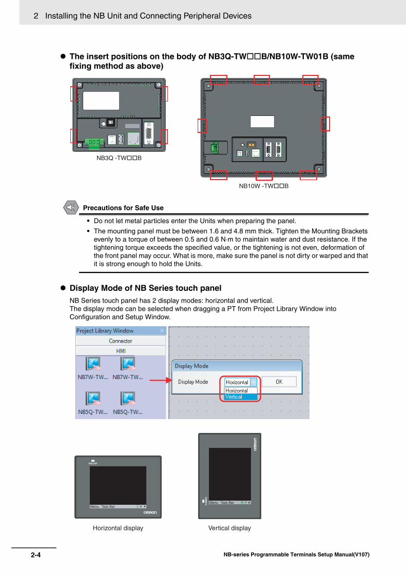
The insert positions on the body of NB3Q-TWB/NB10W-TW01B (same fixing method as above)
Precautions for Safe Use
• Do not let metal particles enter the Units when preparing the panel.
• The mounting panel must be between 1.6 and 4.8 mm thick. Tighten the Mounting Brackets evenly to a torque of between 0.5 and 0.6 N·m to maintain water and dust resistance. If the tightening torque exceeds the specified value, or the tightening is not even, deformation of the front panel may occur. What is more, make sure the panel is not dirty or warped and that it is strong enough to hold the Units.
Display Mode of NB Series touch panelNB Series touch panel has 2 display modes: horizontal and vertical.The display mode can be selected when dragging a PT from Project Library Window into Configuration and Setup Window.
NB3Q -TW��B
NB10W -TW��B
Horizontal display Vertical display
Menu Task BarMenu Task Bar
2-5
2 Installing the NB Unit and Connecting Peripheral Devices
NB-series Programmable Terminals Setup Manual(V107)
2-1 Installing the NB
Unit
2
2-1-3 Connecting the P
ower S
upply
Precautions for Safe Use
• Do not connect an AC power supply to the DC power terminals.• Use a DC power with a slight voltage fluctuation and reinforced or double insulation, and
that will provide a stable output even if the input is momentarily interrupted for 10 ms.Rated Power Supply Voltage: DC 24 V (Allowable range DC 20.4 ~ 27.6 V)
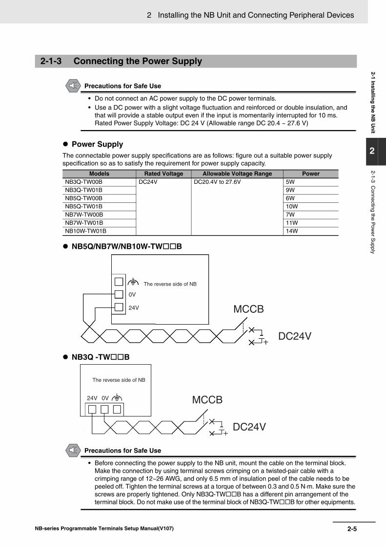
Power SupplyThe connectable power supply specifications are as follows: figure out a suitable power supply specification so as to satisfy the requirement for power supply capacity.
NB5Q/NB7W/NB10W-TWB
NB3Q -TWB
Precautions for Safe Use
• Before connecting the power supply to the NB unit, mount the cable on the terminal block. Make the connection by using terminal screws crimping on a twisted-pair cable with a crimping range of 12~26 AWG, and only 6.5 mm of insulation peel of the cable needs to be peeled off. Tighten the terminal screws at a torque of between 0.3 and 0.5 N·m. Make sure the screws are properly tightened. Only NB3Q-TWB has a different pin arrangement of the terminal block. Do not make use of the terminal block of NB3Q-TWB for other equipments.
2-1-3 Connecting the Power Supply
Models Rated Voltage Allowable Voltage Range PowerNB3Q-TW00B DC24V DC20.4V to 27.6V 5WNB3Q-TW01B 9WNB5Q-TW00B 6WNB5Q-TW01B 10WNB7W-TW00B 7WNB7W-TW01B 11WNB10W-TW01B 14W
0V
The reverse side of NB
MCCB
DC24V
24V
0V
The reverse side of NB
MCCB
DC24V
24V
2 Installing the NB Unit and Connecting Peripheral Devices
2-6 NB-series Programmable Terminals Setup Manual(V107)
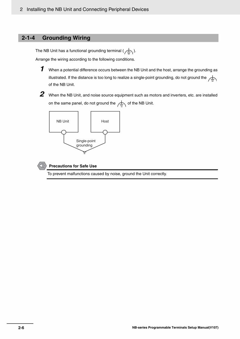
The NB Unit has a functional grounding terminal ( ).
Arrange the wiring according to the following conditions.
1 When a potential difference occurs between the NB Unit and the host, arrange the grounding as
illustrated. If the distance is too long to realize a single-point grounding, do not ground the
of the NB Unit.
2 When the NB Unit, and noise source equipment such as motors and inverters, etc. are installed
on the same panel, do not ground the of the NB Unit.
Precautions for Safe Use
To prevent malfunctions caused by noise, ground the Unit correctly.
2-1-4 Grounding Wiring
NB Unit Host
Single-point grounding
2-7
2 Installing the NB Unit and Connecting Peripheral Devices
NB-series Programmable Terminals Setup Manual(V107)
2-2 Start of N
B S
eries
2
2-2 Start of NB Series
Confirm the hardware are all correctly connected, turn on the power supply, and start the NB-Series.
This part describes the operations of the NB Series when it starts.
When starting the NB Unit for the first time(1) Confirm that the DIP switches SW1 and SW2 on the back side are both ON.
(2) Turn on the power supply of the NB Unit, and with the POWER LED on the front side turning green, the NB Unit starts, entering into the System Setting Mode.
(3) Through the System Setup screen, the system time, starting window No., screen saving time, buzzer and the screen brightness can be set. When the setup is finished, turn OFF the power supply, turn OFF both of the DIP switches, SW1 and SW2, and then switch on the power supply again.
When starting the NB Unit after downloading the screen data to it.(1) Confirm that the DIP switches SW1 and SW2 on the back side are both OFF.
(2) Turn on the power supply of the NB Unit, and with the POWER LED on the front side turning green, the NB Unit starts.
(3) The starting screen of the screen data downloaded to the NB Unit will be shown.
Entering into Calibrate Mode(1) Confirm that the DIP switches SW1 and SW2 on the back side are respectively OFF and
ON.
(2) Turn on the power supply of the NB Unit, and with the POWER LED on the front side turning green, the NB Unit starts.
(3) When the user touches the panel, a symbol “+” will pop up on the screen, with which the touch control precision level can be calibrated.
Precautions for Safe Use
Confirm the safety of the system before turning ON or OFF the power supply, or pressing the reset button.
2 Installing the NB Unit and Connecting Peripheral Devices
2-8 NB-series Programmable Terminals Setup Manual(V107)
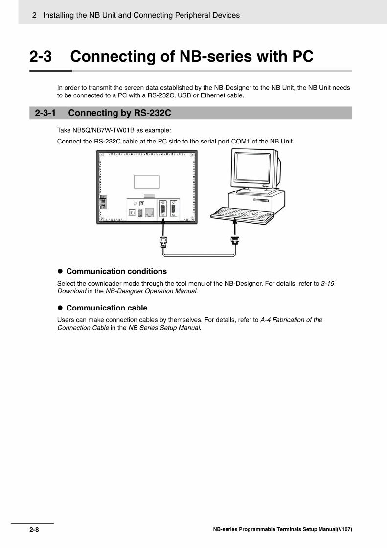
2-3 Connecting of NB-series with PC
In order to transmit the screen data established by the NB-Designer to the NB Unit, the NB Unit needs to be connected to a PC with a RS-232C, USB or Ethernet cable.
Take NB5Q/NB7W-TW01B as example:
Connect the RS-232C cable at the PC side to the serial port COM1 of the NB Unit.
Communication conditionsSelect the downloader mode through the tool menu of the NB-Designer. For details, refer to 3-15 Download in the NB-Designer Operation Manual.
Communication cableUsers can make connection cables by themselves. For details, refer to A-4 Fabrication of the Connection Cable in the NB Series Setup Manual.
2-3-1 Connecting by RS-232C
2-9
2 Installing the NB Unit and Connecting Peripheral Devices
NB-series Programmable Terminals Setup Manual(V107)
2-3 Connecting of N
B-series w
ith PC
2
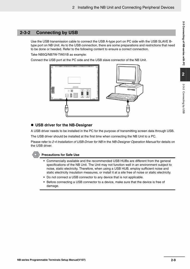
2-3-2 Connecting by U
SB
Use the USB transmission cable to connect the USB A-type port on PC side with the USB SLAVE B-type port on NB Unit. As to the USB connection, there are some preparations and restrictions that need to be done or heeded. Refer to the following content to ensure a correct connection.
Take NB5Q/NB7W-TW01B as example:
Connect the USB port at the PC side and the USB slave connector of the NB Unit.
USB driver for the NB-DesignerA USB driver needs to be installed in the PC for the purpose of transmitting screen data through USB.
The USB driver should be installed at the first time when connecting the NB Unit to a PC.
Please refer to 2-4 Installation of USB-Driver for NB in the NB-Designer Operation Manual for details on the USB driver.
Precautions for Safe Use
• Commercially available and the recommended USB HUBs are different from the general specifications of the NB Unit. The Unit may not function well in an environment subject to noise, static electricity. Therefore, when using a USB HUB, employ sufficient noise and static electricity insulation measures, or install it at a site free of noise or static electricity.
• Do not connect a USB connector to any device that is not applicable.
• Before connecting a USB connector to a device, make sure that the device is free of damage.
2-3-2 Connecting by USB
2 Installing the NB Unit and Connecting Peripheral Devices
2-10 NB-series Programmable Terminals Setup Manual(V107)
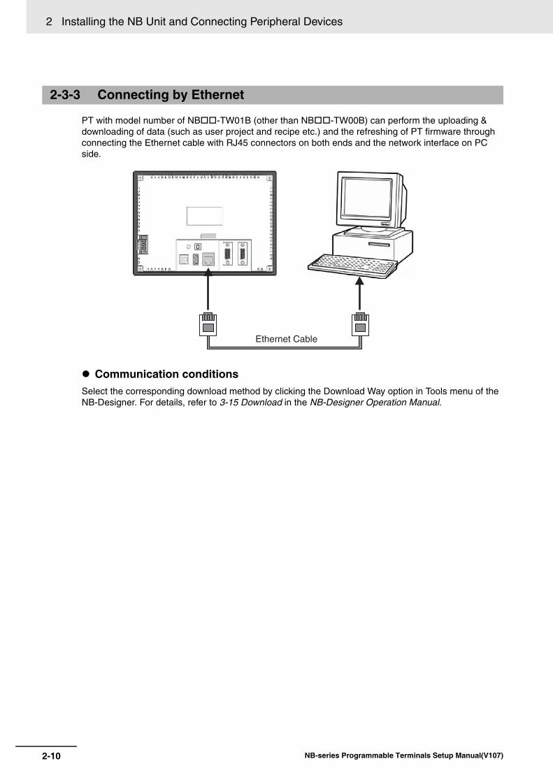
PT with model number of NB-TW01B (other than NB-TW00B) can perform the uploading & downloading of data (such as user project and recipe etc.) and the refreshing of PT firmware through connecting the Ethernet cable with RJ45 connectors on both ends and the network interface on PC side.
Communication conditionsSelect the corresponding download method by clicking the Download Way option in Tools menu of the NB-Designer. For details, refer to 3-15 Download in the NB-Designer Operation Manual.
2-3-3 Connecting by Ethernet
Ethernet Cable
2-11
2 Installing the NB Unit and Connecting Peripheral Devices
NB-series Programmable Terminals Setup Manual(V107)
2-4 Serial C
omm
unication Connection
2
2-4-1 Host Link C
onnection Method
2-4 Serial Communication Connection
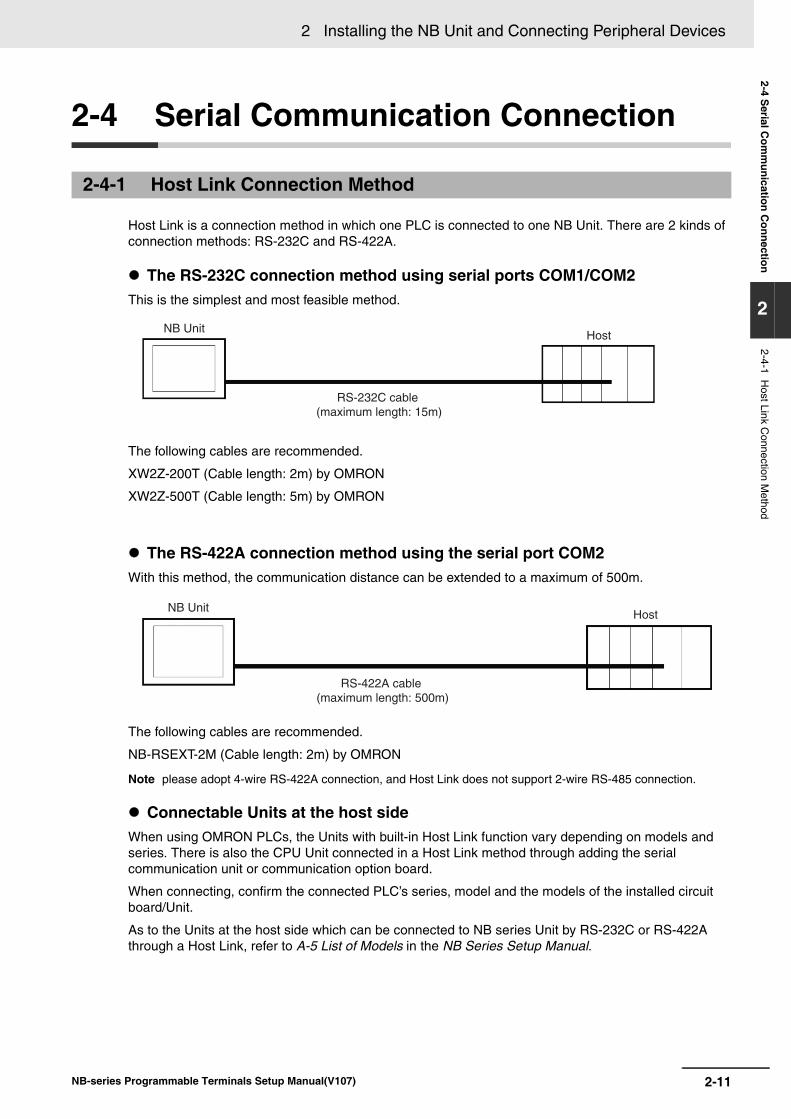
Host Link is a connection method in which one PLC is connected to one NB Unit. There are 2 kinds of connection methods: RS-232C and RS-422A.
The RS-232C connection method using serial ports COM1/COM2This is the simplest and most feasible method.
The following cables are recommended.
XW2Z-200T (Cable length: 2m) by OMRON
XW2Z-500T (Cable length: 5m) by OMRON
The RS-422A connection method using the serial port COM2With this method, the communication distance can be extended to a maximum of 500m.
The following cables are recommended.
NB-RSEXT-2M (Cable length: 2m) by OMRON
Note please adopt 4-wire RS-422A connection, and Host Link does not support 2-wire RS-485 connection.
Connectable Units at the host sideWhen using OMRON PLCs, the Units with built-in Host Link function vary depending on models and series. There is also the CPU Unit connected in a Host Link method through adding the serial communication unit or communication option board.
When connecting, confirm the connected PLC’s series, model and the models of the installed circuit board/Unit.
As to the Units at the host side which can be connected to NB series Unit by RS-232C or RS-422A through a Host Link, refer to A-5 List of Models in the NB Series Setup Manual.
2-4-1 Host Link Connection Method
RS-232C cable(maximum length: 15m)
NB UnitHost
RS-422A cable(maximum length: 500m)
NB UnitHost
2 Installing the NB Unit and Connecting Peripheral Devices
2-12 NB-series Programmable Terminals Setup Manual(V107)
Communication settingThe communication settings need to be set as following values before carrying out communications in the Use Host link.
Settings at the NB Unit should be specified from the [Configuration and Setup Window] in NB-Designer. For details, refer to 3-10-8 COM1/COM2 Setting in the NB-Designer Operation Manual.
For communication settings at the host side, refer to the related PLC manuals as needed.
Select the RS-232C method for COM1, and one from RS-232C and RS-422A for COM2 (NB3Q-TWB is not equipped with serial port COM2.).
PT with the model number of NB-TW01B, which supports Ethernet, can connect single PLC or multiple PLCs simultaneously through the Ethernet (through the router). When connecting with multiple PLCs, it can connect the Host manufactured by the same manufacture or different manufactures simultaneously.
Note Multiple Communications systems cannot be used simultaneously by the same COM port.
The example of NB5Q/NB7W/NB10W-TW01B connecting with 3 PLCs simultaneously is as shown below:
Precautions for Safe Use
• Always keep the connector screws firmly tightened after the communication cable is connected.
• The maximum tensile load for cables is 30N. Do not apply loads greater than this.
• The communication cables of the COM1 and COM2 connectors are not interchangeable. Confirm the pins of the ports before carrying out communications.(NB3Q-TW00B and NB3Q-TW01B only have COM1.)
Items SettingsData bit 7bit
Stop bit 2bit
Parity check Even
Communication speed Any value, but the values for the NB Unit and the host must be the same.
Station No. 00
2-4-2 Connecting more than one PLC
COM1 RS-232C cable
Ethernet cable
COM2 RS-232C/422A/485 cable
NB UnitPLC1
PLC2
PLC3
2-13
2 Installing the NB Unit and Connecting Peripheral Devices
NB-series Programmable Terminals Setup Manual(V107)
2-4 Serial C
omm
unication Connection
2
2-4-3 Settings for each U
nit
When connecting with the serial communication ports, the settings for each Unit are as follows:
CP1L-L14/L20/M30/M40/M60 modelsCP1H-X40/XA40/Y20 modelsCP1E-N14/N20 modelsCP1E-N30/N40/N60/NA20 modelsCP1L-EL20/EM30/EM40 models
PLC System Settings AreaWrite settings directly into the [PLC System Settings Area] with a peripheral tool (CX-Programmer, etc.) based on the model and port of the host.
*1 The channel No. of CP1L/H is PLC Setup area.
*2 The communication speed should be set to the same value as that of the NB Unit.
Settings for the front-side DIP SwitchesSet the front-side DIP switches so as to validate the settings for [PLC System Settings Area].Set the SW4 to OFF when serial port 1 is used, set SW5 to OFF when serial port 2 is used. As the CP1L-L has only one serial port, it has no DIP switch SW5.
2-4-3 Settings for each Unit
When connecting to CP-Series CPU Units
Host model and Port No. Channel No. (*1) Write Value SettingCP1L-M30/M40/M60, serial port 1CP1H-X40/XA40/Y20, serial port 1CP1L-EM30/EM40, serial port 1
144 8000 Use Host Link
145 0000~000A(*2) Communication speed
147 0000~001F Unit number
CP1L-L14/L20, serial port 1CP1L-M30/M40/M60, serial port 2CP1H-X40/XA40/Y20, serial port 2CP1L-EL20, serial port 1CP1L-EM30/EM40, serial port 2
160 8000 Use Host Link
161 0000~000A(*2) Communication speed
163 0000~001F Unit number
Host model and Port No. Channel No. Write Value SettingCP1E-N14/N20, serial port 1CP1E-N30/N40/N60/NA20, serial port 1
A617.15~12 0 Use Host Link
A617.11~08 0, 3~A(*2) Communication speed
A617.07~00 00 7 data bits, 2 stop bits, Even
CP1E-N30/N40/N60/NA20, serial port 2
A618.15~12 0 Use Host Link
A618.11~08 0, 3~A(*2) Communication speed
A618.07~00 00 7 data bits, 2 stop bits, Even
CP1L-MCP1H
ON1
23
45
6 CP1L-L
ON1
23
4
2 Installing the NB Unit and Connecting Peripheral Devices
2-14 NB-series Programmable Terminals Setup Manual(V107)
C200HX/HG/HE(-Z), CPM1, CPM2, CQM1H type CPU Units
Connection MethodsThe connection methods for the CPU Units of different PLC models.
PLC System Settings AreaWrite settings directly into the [PLC System Settings Area] (Data memory) with a peripheral tool (CX-Programmer, etc.) based on the model and port of the host.
For RS-232C
*1 The RS-232C port of the Communication Board.*2 The RS-232C port of the Serial Communication Board.*3 is the set value of the communication speed. Set the communication speed to the same value as that of
the NB Unit.*4 Standard settings of the Communication conditions are as follows:
Start bit: 1 bit, Data bit: 7 bit, Stop bit: 2 bit, parity check: even
When connecting to C-Series CPU Units
PLC Models RS-232C connection RS-422A connectionC200HX/HG/HE(-Z) • Connect to the RS-232C port built in the CPU Unit
• Connect to the RS-232C port (Ports A, B) of the serial communication board
• Connect to the RS-422A port (port A) of the serial communication board
CPM1A • Connect to the peripheral port with a dedicated RS-232C adaptor (CPM1-CIF01).
• Connect to the peripheral port with a dedicated RS-422A adaptor (CPM1-CIF11 type).
CPM2A • Connect to the RS-232C port built in the CPU Unit• Connect to the peripheral port with a dedicated
RS-232C adaptor (CPM1-CIF01).
• Connect to the peripheral port with a dedicated RS-422A adaptor(CPM1-CIF11 type).
CPM2C • Connect to the RS-232C port built in the CPU Unit or the peripheral port with a dedicated conversion cable (CPM2C-CN111 type, CS1W-CN118 type and CS1W-CN114 type) (CPM2C-CN111 type is a cable that divides the Unit port into the RS-232C port built in the CPU Unit and the peripheral port. When connecting to the peripheral port, a RS-232C adaptor (CPM1-CIF01 type) is also needed to be connected.)
• Connect to the peripheral port with a dedicated conversion cable (CPM2C-CN111 type or CS1W-CN114 type) and a RS-422A adaptor (CPM1-CIF11 type) (CPM2C-CN111 type is a cable that divides the Unit port into the RS-232C port built in the CPU Unit and the peripheral port).
CQM1H • Connect to the RS-232C port built in the CPU Unit• Connect to the peripheral port with a conversion
cable (CS1W-CN118 type)Connect to the RS-232C port (Port 1) of the serial communication board
• Connect to the RS-422A port (Port 2) of the serial communication board
Host Model Channel No.
Write Value Setting
The RS-232C port built in C200HX/HG/HE(-Z), CPM2A, CPM2C, CQM1H
DM6645 0001 Use Host Link
DM6646 03(*3) Communication conditions are standard settings. (*4)
DM6648 0000 Unit No. 00
CPM1A DM6650 0001 Use Host Link
DM6651 03(*3) Communication conditions are standard settings. (*4)
DM6653 0000 Unit No. 00
Port A of C200HX/HG/HE(-Z) (*1)Port 1 of CQM1H (*2)
DM6555 0001 Use Host Link
DM6556 03(*3) Communication conditions are standard settings. (*4)
DM6558 0000 Unit No. 00
Port B of C200HX/HG/HE(-Z) (*1)
DM6550 0001 Use Host Link
DM6551 03(*3) Communication conditions are standard settings. (*4)
DM6553 0000 Unit No. 00
2-15
2 Installing the NB Unit and Connecting Peripheral Devices
NB-series Programmable Terminals Setup Manual(V107)
2-4 Serial C
omm
unication Connection
2
2-4-3 Settings for each U
nit
For RS-422A
*1 The RS-422A port of the Communication Board
*2 The RS-422A port of the Serial Communication Board
*3 is the set value of the communication speed. Set the communication speed to the same value as that of the NB Unit.
*4 Standard settings of the Communication conditions are as follows: Start bit: 1 bit, Data bit: 7 bit, Stop bit: 2 bit, parity check: even
For operations on [PLC System Settings Area], refer to the manual of the PLC employed.
Additional Information
When the NB Unit communicates with the C-Series via Host Link while the PLC is in the Run mode, the mode will be automatically switched to the Monitor mode. Make sure that there will be no problem with the actual system before using them.
Connection methods for CPM2CCPM2C only has a connector with the same shape of the CS-Series’ peripheral port, but the signal cables inside are classified as used for the RS-232C port built in the CPU Unit and for the peripheral port. Therefore, when using CPM2C, differentiate between the settings for the RS-232C port built in the CPU and for the peripheral port based on the conversion cable and port employed to ensure correct use. Besides, when using a simple communication device (CPM2C-CIF21 type), connect to the RS-232C port. For details, refer to the CPM2C Operation Manual (W356).
Use a self-made connection cable to connect the NB Unit and CPM2C. Connect to CPM2C’s built-in RS-232C port instead of the peripheral port.
When using a simple communication device (CPM2C-CIF21 type), connect to the RS-232C port directly.
Host Model Channel No. Write Value SettingPort A of C200HX/HG/HE(-Z) (*1)
DM6555 0001 Use Host Link
DM6556 03(*3) Communication conditions are standard settings. (*4)
DM6558 0000 Unit No. 00
Port 2 of CQM1H (*2)
DM6550 0001 Use Host Link
DM6551 03(*3) Communication conditions are standard settings. (*4)
DM6553 0000 Unit No. 00
Port connected to the PT PLC System Settings
CS1W-CN118 type port(D-Sub 9-pin) Carry out settings for the built-in RS-232C port
CS1W-CN118 type
RS-232C port(D-Sub 9-pin socket)
CPM2C
RS-232C port
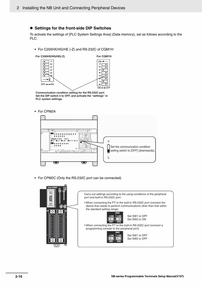
2 Installing the NB Unit and Connecting Peripheral Devices
2-16 NB-series Programmable Terminals Setup Manual(V107)
Settings for the front-side DIP SwitchesTo activate the settings of [PLC System Settings Area] (Data memory), set as follows according to the PLC:
• For C200HX/HG/HE (-Z) and RS-232C of CQM1H
• For CPM2A
• For CPM2C (Only the RS-232C port can be connected)
For C200HX/HG/HE(-Z)
Communication condition setting for the RS-232C portSet the DIP switch 5 to OFF, and activate the “settings” inPLC system settings.
For CQM1H
Set the communication conditionsetting switch to [OFF] (downwards).
• When connecting the PT to the built-in RS-232C port (connect the device that needs to perform communications other than that within the standard setting range)
• When connecting the PT to the built-in RS-232C port (connect a programming console to the peripheral port)
Set SW1 to OFFSet SW2 to ON
Set SW1 to OFFSet SW2 to OFF
Carry out settings according to the using conditions of the peripheral port and built-in RS-232C port.
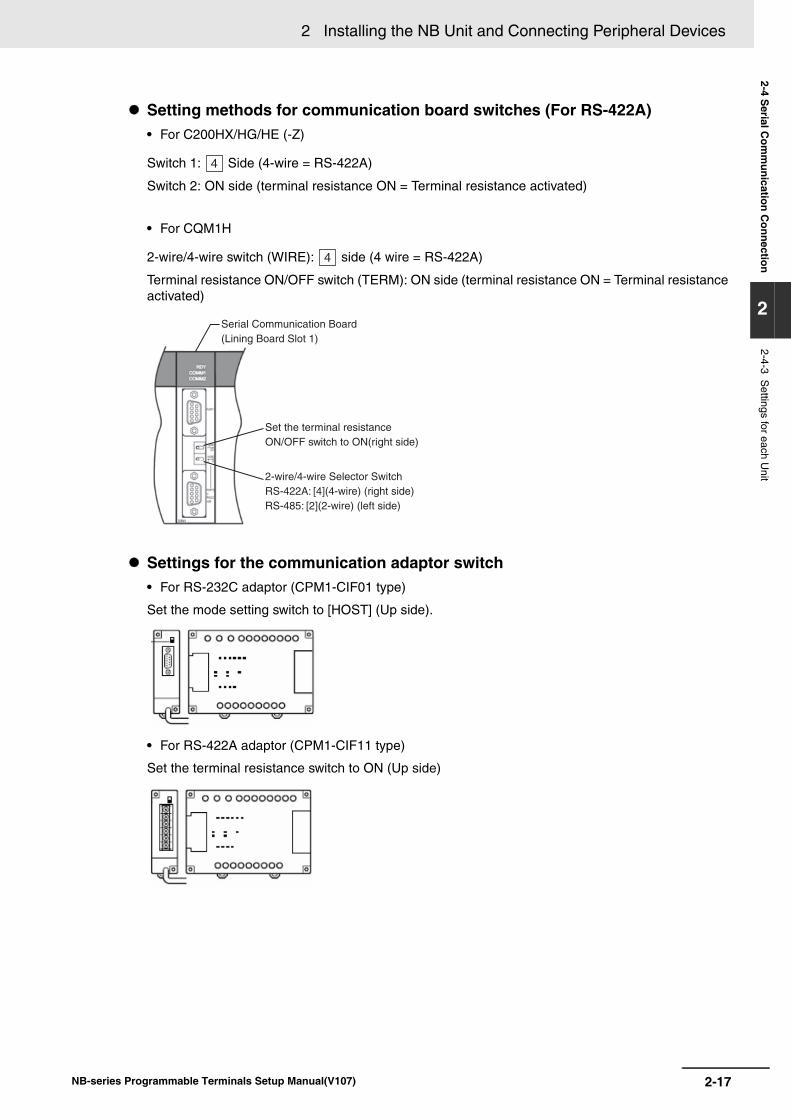
2-17
2 Installing the NB Unit and Connecting Peripheral Devices
NB-series Programmable Terminals Setup Manual(V107)
2-4 Serial C
omm
unication Connection
2
2-4-3 Settings for each U
nit
Setting methods for communication board switches (For RS-422A)• For C200HX/HG/HE (-Z)
Switch 1: Side (4-wire = RS-422A)
Switch 2: ON side (terminal resistance ON = Terminal resistance activated)
• For CQM1H
2-wire/4-wire switch (WIRE): side (4 wire = RS-422A)
Terminal resistance ON/OFF switch (TERM): ON side (terminal resistance ON = Terminal resistance activated)
Settings for the communication adaptor switch• For RS-232C adaptor (CPM1-CIF01 type)
Set the mode setting switch to [HOST] (Up side).
• For RS-422A adaptor (CPM1-CIF11 type)
Set the terminal resistance switch to ON (Up side)
4
4
Serial Communication Board(Lining Board Slot 1)
Set the terminal resistanceON/OFF switch to ON(right side)
2-wire/4-wire Selector SwitchRS-422A: [4](4-wire) (right side)RS-485: [2](2-wire) (left side)
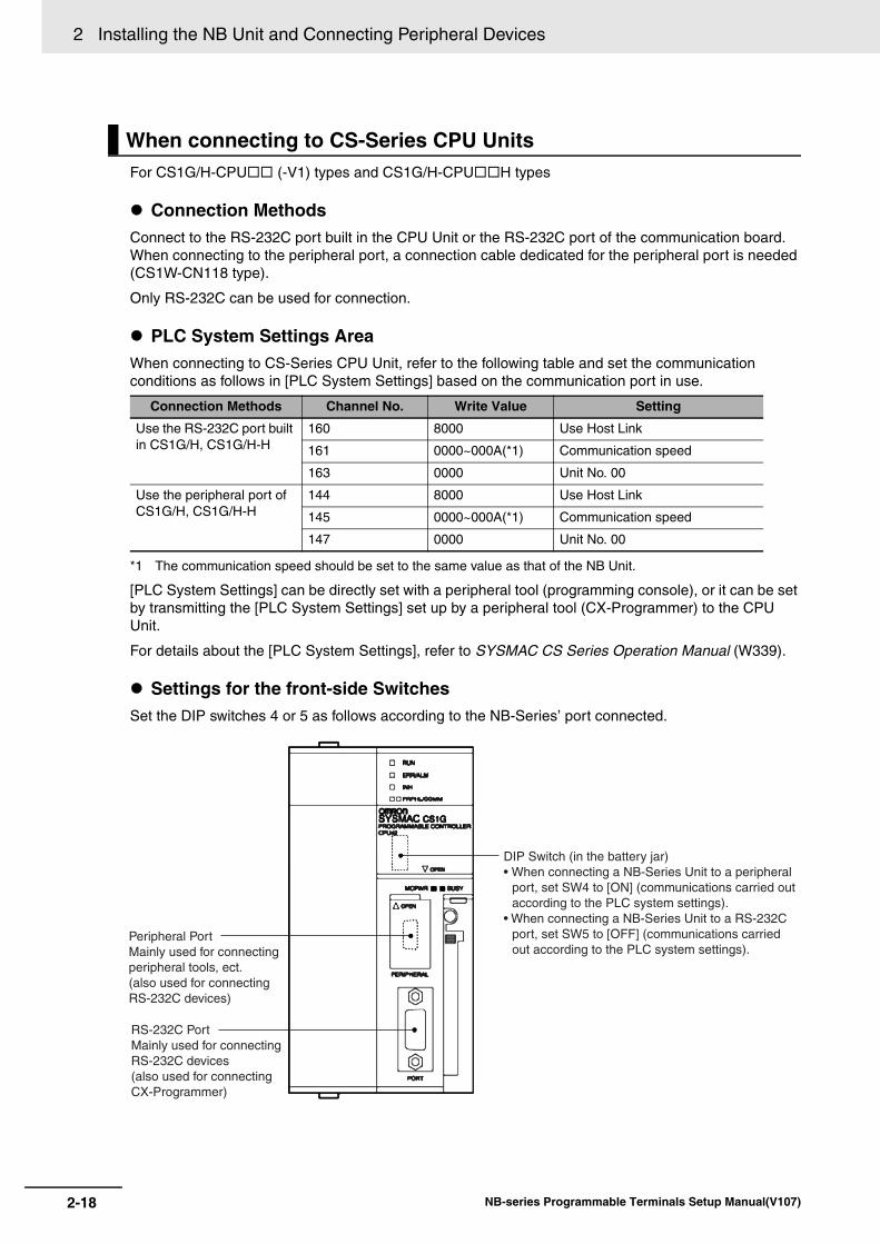
2 Installing the NB Unit and Connecting Peripheral Devices
2-18 NB-series Programmable Terminals Setup Manual(V107)
For CS1G/H-CPU (-V1) types and CS1G/H-CPUH types
Connection MethodsConnect to the RS-232C port built in the CPU Unit or the RS-232C port of the communication board. When connecting to the peripheral port, a connection cable dedicated for the peripheral port is needed (CS1W-CN118 type).
Only RS-232C can be used for connection.
PLC System Settings AreaWhen connecting to CS-Series CPU Unit, refer to the following table and set the communication conditions as follows in [PLC System Settings] based on the communication port in use.
*1 The communication speed should be set to the same value as that of the NB Unit.
[PLC System Settings] can be directly set with a peripheral tool (programming console), or it can be set by transmitting the [PLC System Settings] set up by a peripheral tool (CX-Programmer) to the CPU Unit.
For details about the [PLC System Settings], refer to SYSMAC CS Series Operation Manual (W339).
Settings for the front-side SwitchesSet the DIP switches 4 or 5 as follows according to the NB-Series’ port connected.
When connecting to CS-Series CPU Units
Connection Methods Channel No. Write Value Setting
Use the RS-232C port built in CS1G/H, CS1G/H-H
160 8000 Use Host Link
161 0000~000A(*1) Communication speed
163 0000 Unit No. 00
Use the peripheral port of CS1G/H, CS1G/H-H
144 8000 Use Host Link
145 0000~000A(*1) Communication speed
147 0000 Unit No. 00
DIP Switch (in the battery jar)• When connecting a NB-Series Unit to a peripheral
port, set SW4 to [ON] (communications carried out according to the PLC system settings).
• When connecting a NB-Series Unit to a RS-232C port, set SW5 to [OFF] (communications carried out according to the PLC system settings).
Peripheral PortMainly used for connectingperipheral tools, ect.(also used for connectingRS-232C devices)
RS-232C PortMainly used for connectingRS-232C devices(also used for connectingCX-Programmer)
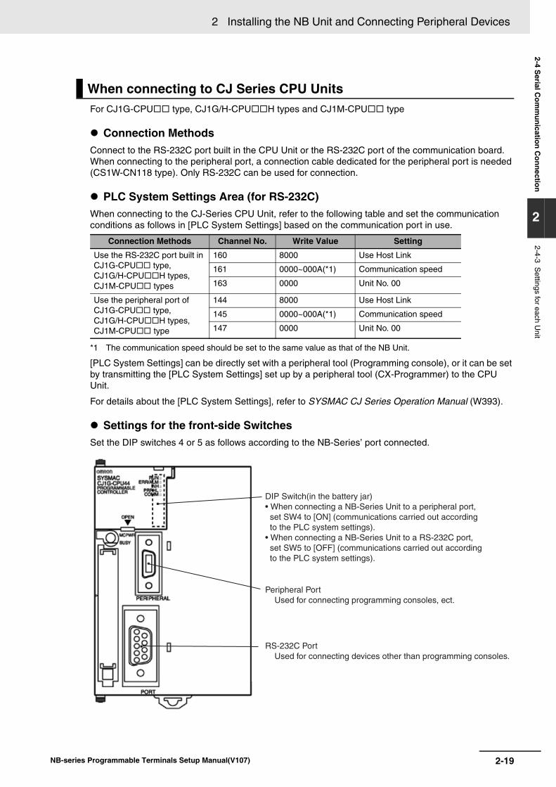
2-19
2 Installing the NB Unit and Connecting Peripheral Devices
NB-series Programmable Terminals Setup Manual(V107)
2-4 Serial C
omm
unication Connection
2
2-4-3 Settings for each U
nit
For CJ1G-CPU type, CJ1G/H-CPUH types and CJ1M-CPU type
Connection MethodsConnect to the RS-232C port built in the CPU Unit or the RS-232C port of the communication board. When connecting to the peripheral port, a connection cable dedicated for the peripheral port is needed (CS1W-CN118 type). Only RS-232C can be used for connection.
PLC System Settings Area (for RS-232C)When connecting to the CJ-Series CPU Unit, refer to the following table and set the communication conditions as follows in [PLC System Settings] based on the communication port in use.
*1 The communication speed should be set to the same value as that of the NB Unit.
[PLC System Settings] can be directly set with a peripheral tool (Programming console), or it can be set by transmitting the [PLC System Settings] set up by a peripheral tool (CX-Programmer) to the CPU Unit.
For details about the [PLC System Settings], refer to SYSMAC CJ Series Operation Manual (W393).
Settings for the front-side SwitchesSet the DIP switches 4 or 5 as follows according to the NB-Series’ port connected.
When connecting to CJ Series CPU Units
Connection Methods Channel No. Write Value Setting
Use the RS-232C port built in CJ1G-CPU type, CJ1G/H-CPUH types, CJ1M-CPU types
160 8000 Use Host Link
161 0000~000A(*1) Communication speed
163 0000 Unit No. 00
Use the peripheral port of CJ1G-CPU type, CJ1G/H-CPUH types, CJ1M-CPU type
144 8000 Use Host Link
145 0000~000A(*1) Communication speed
147 0000 Unit No. 00
Peripheral Port Used for connecting programming consoles, ect.
RS-232C Port Used for connecting devices other than programming consoles.
DIP Switch(in the battery jar)• When connecting a NB-Series Unit to a peripheral port, set SW4 to [ON] (communications carried out according to the PLC system settings).• When connecting a NB-Series Unit to a RS-232C port, set SW5 to [OFF] (communications carried out according to the PLC system settings).
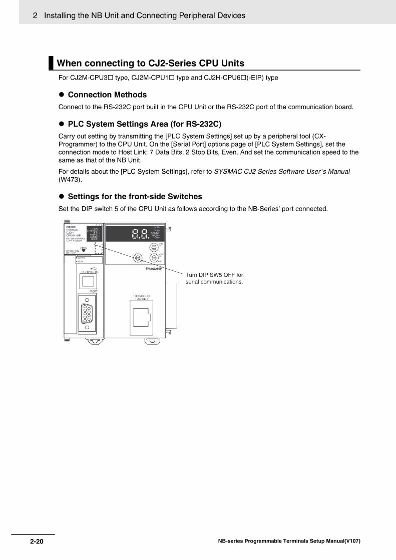
2 Installing the NB Unit and Connecting Peripheral Devices
2-20 NB-series Programmable Terminals Setup Manual(V107)
For CJ2M-CPU3 type, CJ2M-CPU1 type and CJ2H-CPU6(-EIP) type
Connection MethodsConnect to the RS-232C port built in the CPU Unit or the RS-232C port of the communication board.
PLC System Settings Area (for RS-232C)Carry out setting by transmitting the [PLC System Settings] set up by a peripheral tool (CX-Programmer) to the CPU Unit. On the [Serial Port] options page of [PLC System Settings], set the connection mode to Host Link: 7 Data Bits, 2 Stop Bits, Even. And set the communication speed to the same as that of the NB Unit.
For details about the [PLC System Settings], refer to SYSMAC CJ2 Series Software User ’s Manual (W473).
Settings for the front-side SwitchesSet the DIP switch 5 of the CPU Unit as follows according to the NB-Series’ port connected.
When connecting to CJ2-Series CPU Units
Turn DIP SW5 OFF for serial communications.
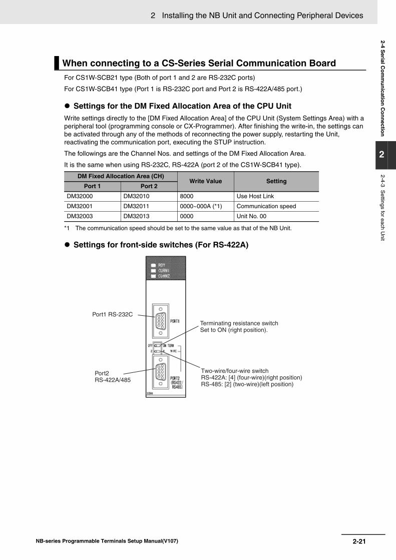
2-21
2 Installing the NB Unit and Connecting Peripheral Devices
NB-series Programmable Terminals Setup Manual(V107)
2-4 Serial C
omm
unication Connection
2
2-4-3 Settings for each U
nit
For CS1W-SCB21 type (Both of port 1 and 2 are RS-232C ports)
For CS1W-SCB41 type (Port 1 is RS-232C port and Port 2 is RS-422A/485 port.)
Settings for the DM Fixed Allocation Area of the CPU UnitWrite settings directly to the [DM Fixed Allocation Area] of the CPU Unit (System Settings Area) with a peripheral tool (programming console or CX-Programmer). After finishing the write-in, the settings can be activated through any of the methods of reconnecting the power supply, restarting the Unit, reactivating the communication port, executing the STUP instruction.
The followings are the Channel Nos. and settings of the DM Fixed Allocation Area.
It is the same when using RS-232C, RS-422A (port 2 of the CS1W-SCB41 type).
*1 The communication speed should be set to the same value as that of the NB Unit.
Settings for front-side switches (For RS-422A)
When connecting to a CS-Series Serial Communication Board
DM Fixed Allocation Area (CH)Write Value Setting
Port 1 Port 2
DM32000 DM32010 8000 Use Host Link
DM32001 DM32011 0000~000A (*1) Communication speed
DM32003 DM32013 0000 Unit No. 00
Port1 RS-232C
Terminating resistance switch Set to ON (right position).
Two-wire/four-wire switchRS-422A: [4] (four-wire)(right position)RS-485: [2] (two-wire)(left position)
Port2 RS-422A/485
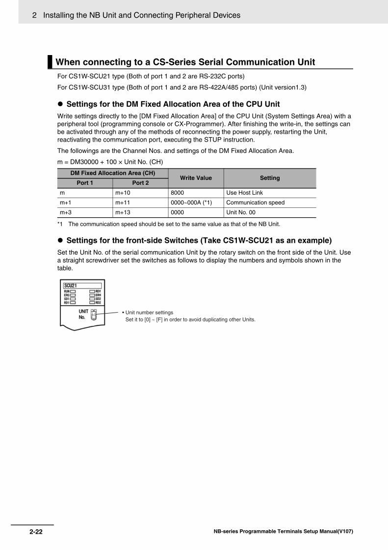
2 Installing the NB Unit and Connecting Peripheral Devices
2-22 NB-series Programmable Terminals Setup Manual(V107)
For CS1W-SCU21 type (Both of port 1 and 2 are RS-232C ports)
For CS1W-SCU31 type (Both of port 1 and 2 are RS-422A/485 ports) (Unit version1.3)
Settings for the DM Fixed Allocation Area of the CPU UnitWrite settings directly to the [DM Fixed Allocation Area] of the CPU Unit (System Settings Area) with a peripheral tool (programming console or CX-Programmer). After finishing the write-in, the settings can be activated through any of the methods of reconnecting the power supply, restarting the Unit, reactivating the communication port, executing the STUP instruction.
The followings are the Channel Nos. and settings of the DM Fixed Allocation Area.
m = DM30000 + 100 × Unit No. (CH)
*1 The communication speed should be set to the same value as that of the NB Unit.
Settings for the front-side Switches (Take CS1W-SCU21 as an example)Set the Unit No. of the serial communication Unit by the rotary switch on the front side of the Unit. Use a straight screwdriver set the switches as follows to display the numbers and symbols shown in the table.
When connecting to a CS-Series Serial Communication Unit
DM Fixed Allocation Area (CH)Write Value Setting
Port 1 Port 2
m m+10 8000 Use Host Link
m+1 m+11 0000~000A (*1) Communication speed
m+3 m+13 0000 Unit No. 00
• Unit number settingsSet it to [0] ~ [F] in order to avoid duplicating other Units.
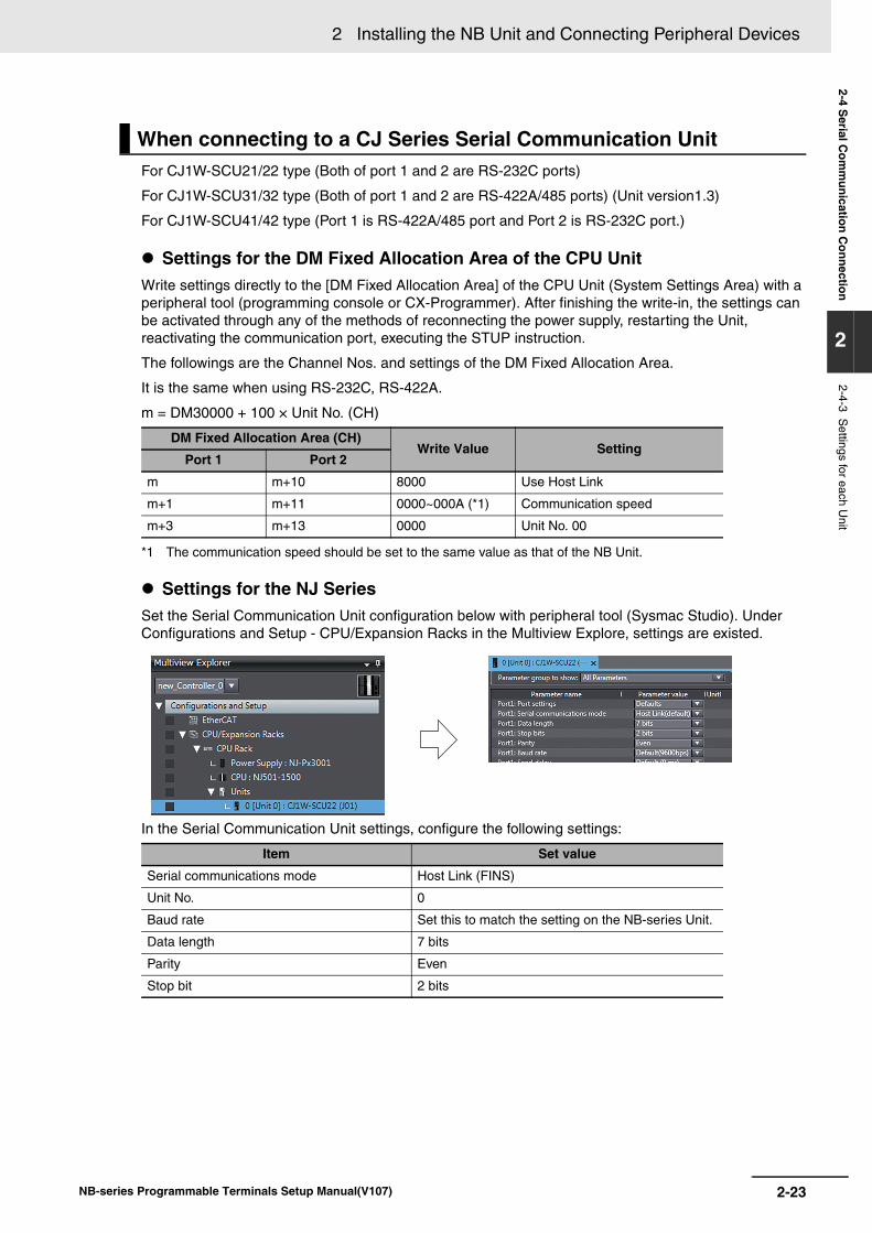
2-23
2 Installing the NB Unit and Connecting Peripheral Devices
NB-series Programmable Terminals Setup Manual(V107)
2-4 Serial C
omm
unication Connection
2
2-4-3 Settings for each U
nit
For CJ1W-SCU21/22 type (Both of port 1 and 2 are RS-232C ports)
For CJ1W-SCU31/32 type (Both of port 1 and 2 are RS-422A/485 ports) (Unit version1.3)
For CJ1W-SCU41/42 type (Port 1 is RS-422A/485 port and Port 2 is RS-232C port.)
Settings for the DM Fixed Allocation Area of the CPU UnitWrite settings directly to the [DM Fixed Allocation Area] of the CPU Unit (System Settings Area) with a peripheral tool (programming console or CX-Programmer). After finishing the write-in, the settings can be activated through any of the methods of reconnecting the power supply, restarting the Unit, reactivating the communication port, executing the STUP instruction.
The followings are the Channel Nos. and settings of the DM Fixed Allocation Area.
It is the same when using RS-232C, RS-422A.
m = DM30000 + 100 × Unit No. (CH)
*1 The communication speed should be set to the same value as that of the NB Unit.
Settings for the NJ SeriesSet the Serial Communication Unit configuration below with peripheral tool (Sysmac Studio). Under Configurations and Setup - CPU/Expansion Racks in the Multiview Explore, settings are existed.
In the Serial Communication Unit settings, configure the following settings:
When connecting to a CJ Series Serial Communication Unit
DM Fixed Allocation Area (CH)Write Value Setting
Port 1 Port 2
m m+10 8000 Use Host Link
m+1 m+11 0000~000A (*1) Communication speed
m+3 m+13 0000 Unit No. 00
Item Set value
Serial communications mode Host Link (FINS)
Unit No. 0
Baud rate Set this to match the setting on the NB-series Unit.
Data length 7 bits
Parity Even
Stop bit 2 bits
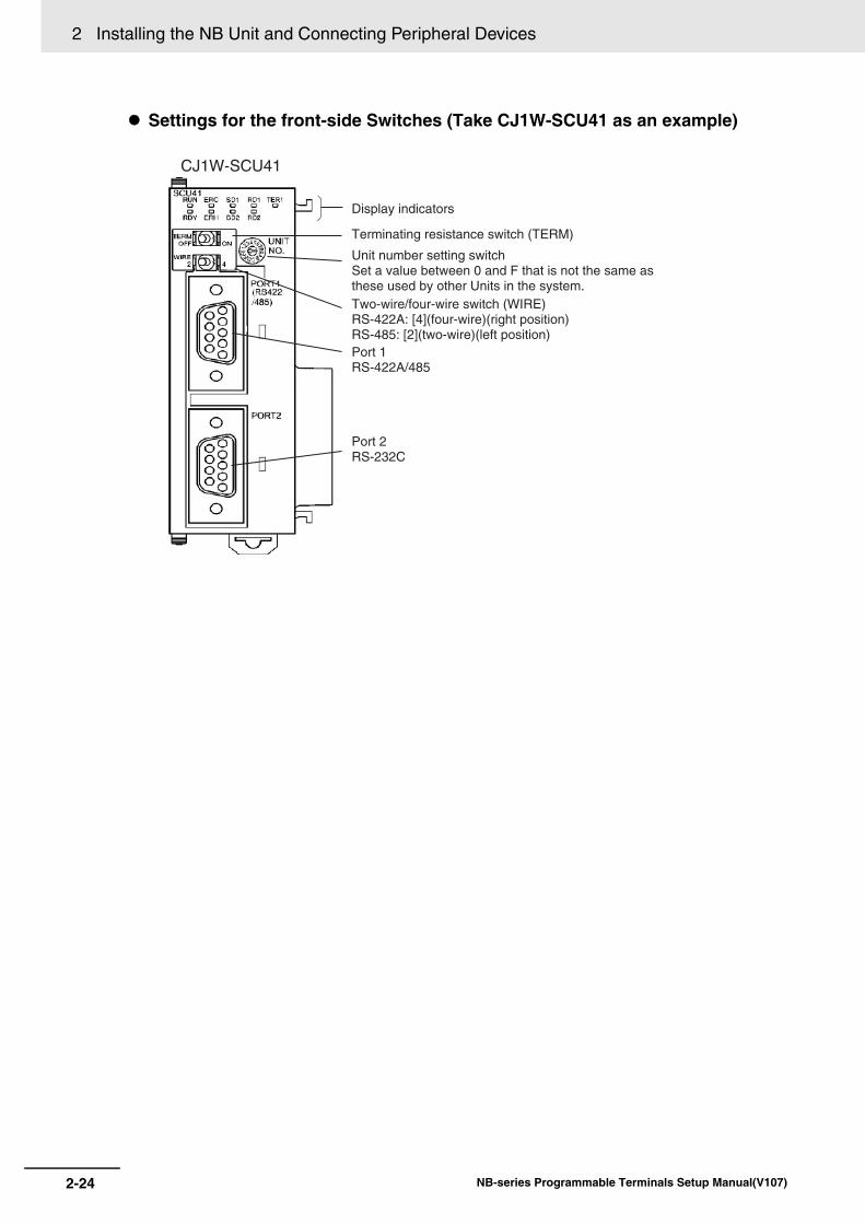
2 Installing the NB Unit and Connecting Peripheral Devices
2-24 NB-series Programmable Terminals Setup Manual(V107)
Settings for the front-side Switches (Take CJ1W-SCU41 as an example)
Display indicators
CJ1W-SCU41
Port 2 RS-232C
Port 1 RS-422A/485
Unit number setting switchSet a value between 0 and F that is not the same as these used by other Units in the system.Two-wire/four-wire switch (WIRE)RS-422A: [4](four-wire)(right position)RS-485: [2](two-wire)(left position)
Terminating resistance switch (TERM)
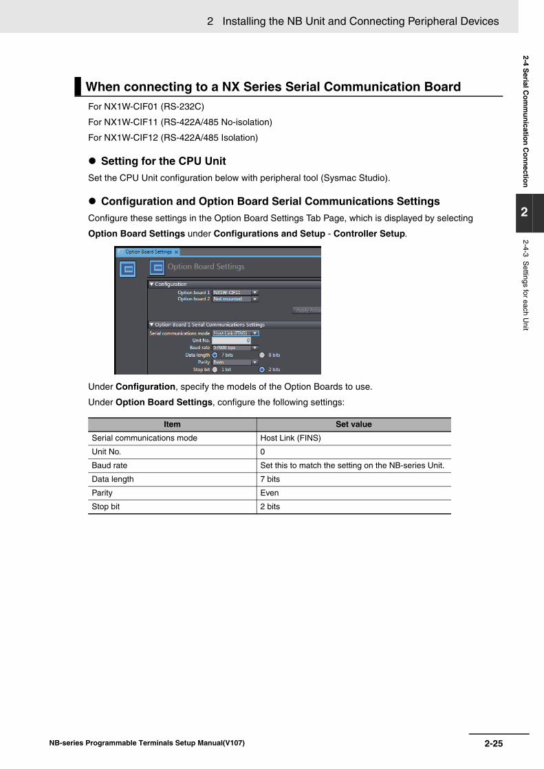
2-25
2 Installing the NB Unit and Connecting Peripheral Devices
NB-series Programmable Terminals Setup Manual(V107)
2-4 Serial C
omm
unication Connection
2
2-4-3 Settings for each U
nit
For NX1W-CIF01 (RS-232C)
For NX1W-CIF11 (RS-422A/485 No-isolation)
For NX1W-CIF12 (RS-422A/485 Isolation)
Setting for the CPU UnitSet the CPU Unit configuration below with peripheral tool (Sysmac Studio).
Configuration and Option Board Serial Communications SettingsConfigure these settings in the Option Board Settings Tab Page, which is displayed by selecting
Option Board Settings under Configurations and Setup - Controller Setup.
Under Configuration, specify the models of the Option Boards to use.
Under Option Board Settings, configure the following settings:
When connecting to a NX Series Serial Communication Board
Item Set value
Serial communications mode Host Link (FINS)
Unit No. 0
Baud rate Set this to match the setting on the NB-series Unit.
Data length 7 bits
Parity Even
Stop bit 2 bits
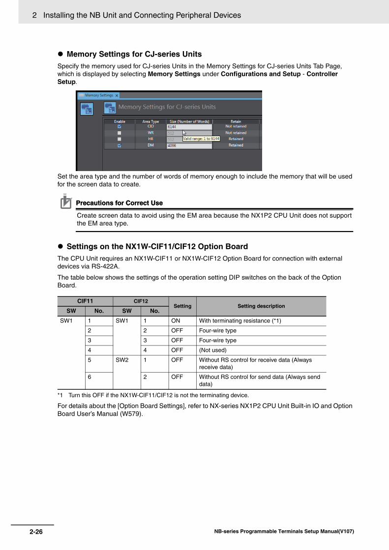
2 Installing the NB Unit and Connecting Peripheral Devices
2-26 NB-series Programmable Terminals Setup Manual(V107)
Memory Settings for CJ-series UnitsSpecify the memory used for CJ-series Units in the Memory Settings for CJ-series Units Tab Page, which is displayed by selecting Memory Settings under Configurations and Setup - Controller Setup.
Set the area type and the number of words of memory enough to include the memory that will be used for the screen data to create.
Precautions for Correct UsePrecautions for Correct Use
Create screen data to avoid using the EM area because the NX1P2 CPU Unit does not support the EM area type.
Settings on the NX1W-CIF11/CIF12 Option BoardThe CPU Unit requires an NX1W-CIF11 or NX1W-CIF12 Option Board for connection with external devices via RS-422A.
The table below shows the settings of the operation setting DIP switches on the back of the Option Board.
*1 Turn this OFF if the NX1W-CIF11/CIF12 is not the terminating device.
For details about the [Option Board Settings], refer to NX-series NX1P2 CPU Unit Built-in IO and Option Board User’s Manual (W579).
CIF11 CIF12Setting Setting description
SW No. SW No.
SW1 1 SW1 1 ON With terminating resistance (*1)
2 2 OFF Four-wire type
3 3 OFF Four-wire type
4 4 OFF (Not used)
5 SW2 1 OFF Without RS control for receive data (Always receive data)
6 2 OFF Without RS control for send data (Always send data)
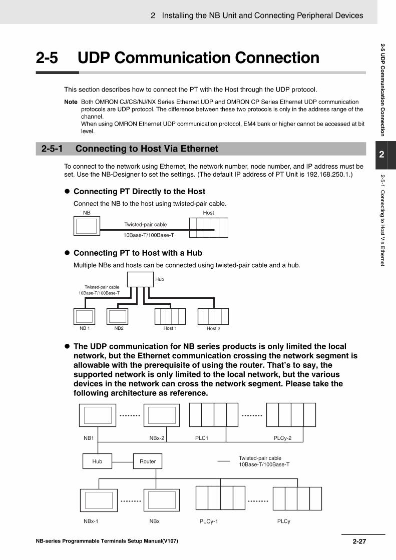
2-27
2 Installing the NB Unit and Connecting Peripheral Devices
NB-series Programmable Terminals Setup Manual(V107)
2-5 UD
P C
omm
unication Connection
2
2-5-1 Connecting to H
ost Via E
thernet
2-5 UDP Communication Connection
This section describes how to connect the PT with the Host through the UDP protocol.
Note Both OMRON CJ/CS/NJ/NX Series Ethernet UDP and OMRON CP Series Ethernet UDP communication protocols are UDP protocol. The difference between these two protocols is only in the address range of the channel.When using OMRON Ethernet UDP communication protocol, EM4 bank or higher cannot be accessed at bit level.
To connect to the network using Ethernet, the network number, node number, and IP address must be set. Use the NB-Designer to set the settings. (The default IP address of PT Unit is 192.168.250.1.)
Connecting PT Directly to the Host Connect the NB to the host using twisted-pair cable.
Connecting PT to Host with a Hub Multiple NBs and hosts can be connected using twisted-pair cable and a hub.
The UDP communication for NB series products is only limited the local network, but the Ethernet communication crossing the network segment is allowable with the prerequisite of using the router. That’s to say, the supported network is only limited to the local network, but the various devices in the network can cross the network segment. Please take the following architecture as reference.
2-5-1 Connecting to Host Via Ethernet
Twisted-pair cable
NB Host
10Base-T/100Base-T
Twisted-pair cable
NB 1 NB2 Host 1
Hub
Host 2
10Base-T/100Base-T
NB1 NBx-2 PLC1 PLCy-2
Hub Router
PLCyPLCy-1NBxNBx-1
Twisted-pair cable 10Base-T/100Base-T
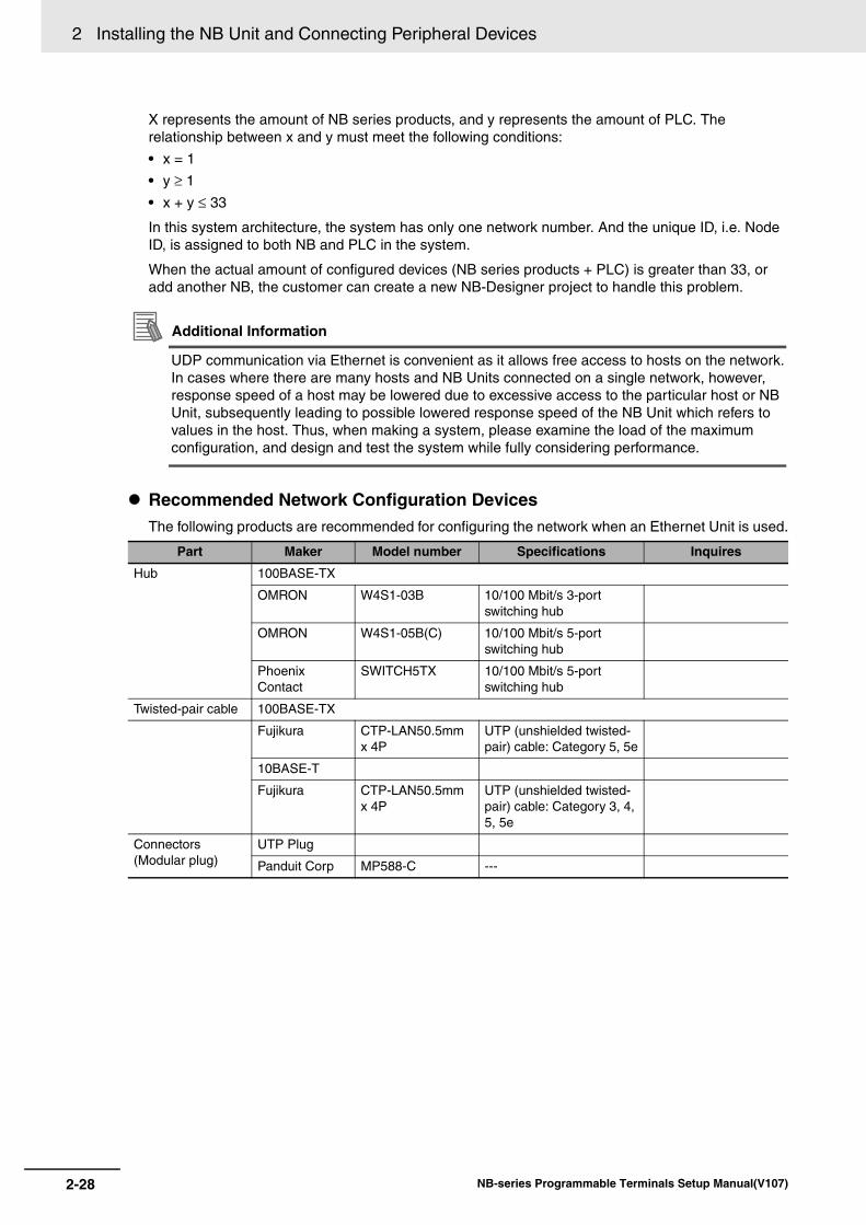
2 Installing the NB Unit and Connecting Peripheral Devices
2-28 NB-series Programmable Terminals Setup Manual(V107)
X represents the amount of NB series products, and y represents the amount of PLC. The relationship between x and y must meet the following conditions:
• x = 1
• y ≥ 1
• x + y ≤ 33
In this system architecture, the system has only one network number. And the unique ID, i.e. Node ID, is assigned to both NB and PLC in the system.
When the actual amount of configured devices (NB series products + PLC) is greater than 33, or add another NB, the customer can create a new NB-Designer project to handle this problem.
Additional Information
UDP communication via Ethernet is convenient as it allows free access to hosts on the network. In cases where there are many hosts and NB Units connected on a single network, however, response speed of a host may be lowered due to excessive access to the particular host or NB Unit, subsequently leading to possible lowered response speed of the NB Unit which refers to values in the host. Thus, when making a system, please examine the load of the maximum configuration, and design and test the system while fully considering performance.
Recommended Network Configuration DevicesThe following products are recommended for configuring the network when an Ethernet Unit is used.
Part Maker Model number Specifications Inquires
Hub 100BASE-TX
OMRON W4S1-03B 10/100 Mbit/s 3-port switching hub
OMRON W4S1-05B(C) 10/100 Mbit/s 5-port switching hub
Phoenix Contact
SWITCH5TX 10/100 Mbit/s 5-port switching hub
Twisted-pair cable 100BASE-TX
Fujikura CTP-LAN50.5mm x 4P
UTP (unshielded twisted- pair) cable: Category 5, 5e
10BASE-T
Fujikura CTP-LAN50.5mm x 4P
UTP (unshielded twisted- pair) cable: Category 3, 4, 5, 5e
Connectors(Modular plug)
UTP Plug
Panduit Corp MP588-C ---
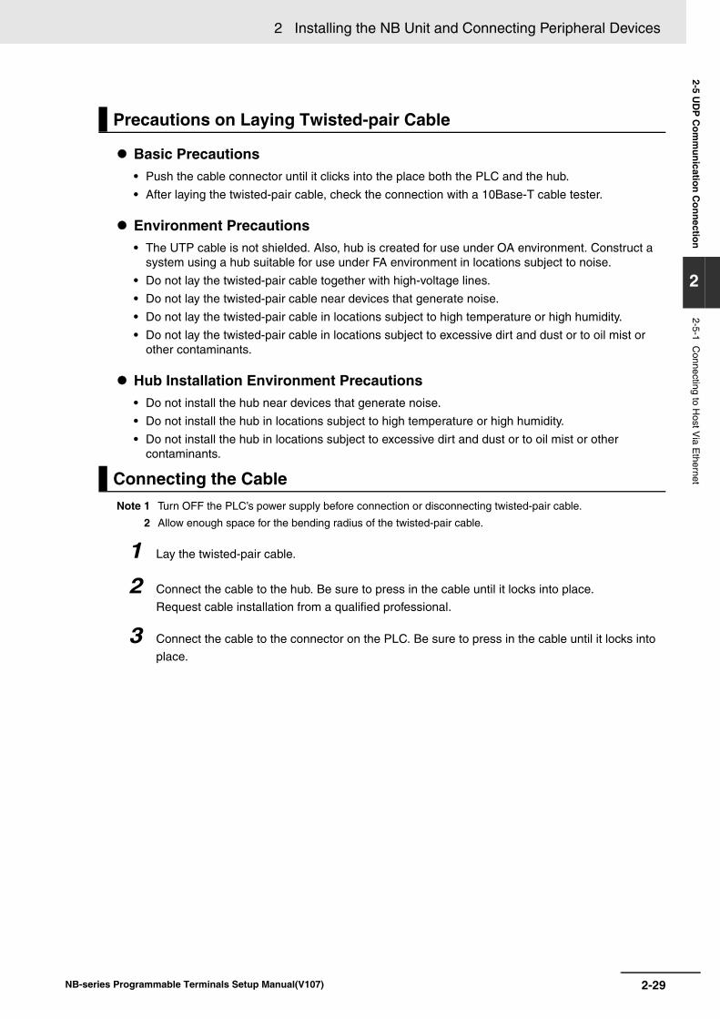
2-29
2 Installing the NB Unit and Connecting Peripheral Devices
NB-series Programmable Terminals Setup Manual(V107)
2-5 UD
P C
omm
unication Connection
2
2-5-1 Connecting to H
ost Via E
thernet
Basic Precautions• Push the cable connector until it clicks into the place both the PLC and the hub.
• After laying the twisted-pair cable, check the connection with a 10Base-T cable tester.
Environment Precautions• The UTP cable is not shielded. Also, hub is created for use under OA environment. Construct a
system using a hub suitable for use under FA environment in locations subject to noise.
• Do not lay the twisted-pair cable together with high-voltage lines.
• Do not lay the twisted-pair cable near devices that generate noise.
• Do not lay the twisted-pair cable in locations subject to high temperature or high humidity.
• Do not lay the twisted-pair cable in locations subject to excessive dirt and dust or to oil mist or other contaminants.
Hub Installation Environment Precautions• Do not install the hub near devices that generate noise.
• Do not install the hub in locations subject to high temperature or high humidity.
• Do not install the hub in locations subject to excessive dirt and dust or to oil mist or other contaminants.
Note 1 Turn OFF the PLC’s power supply before connection or disconnecting twisted-pair cable.
2 Allow enough space for the bending radius of the twisted-pair cable.
1 Lay the twisted-pair cable.
2 Connect the cable to the hub. Be sure to press in the cable until it locks into place.
Request cable installation from a qualified professional.
3 Connect the cable to the connector on the PLC. Be sure to press in the cable until it locks into
place.
Precautions on Laying Twisted-pair Cable
Connecting the Cable
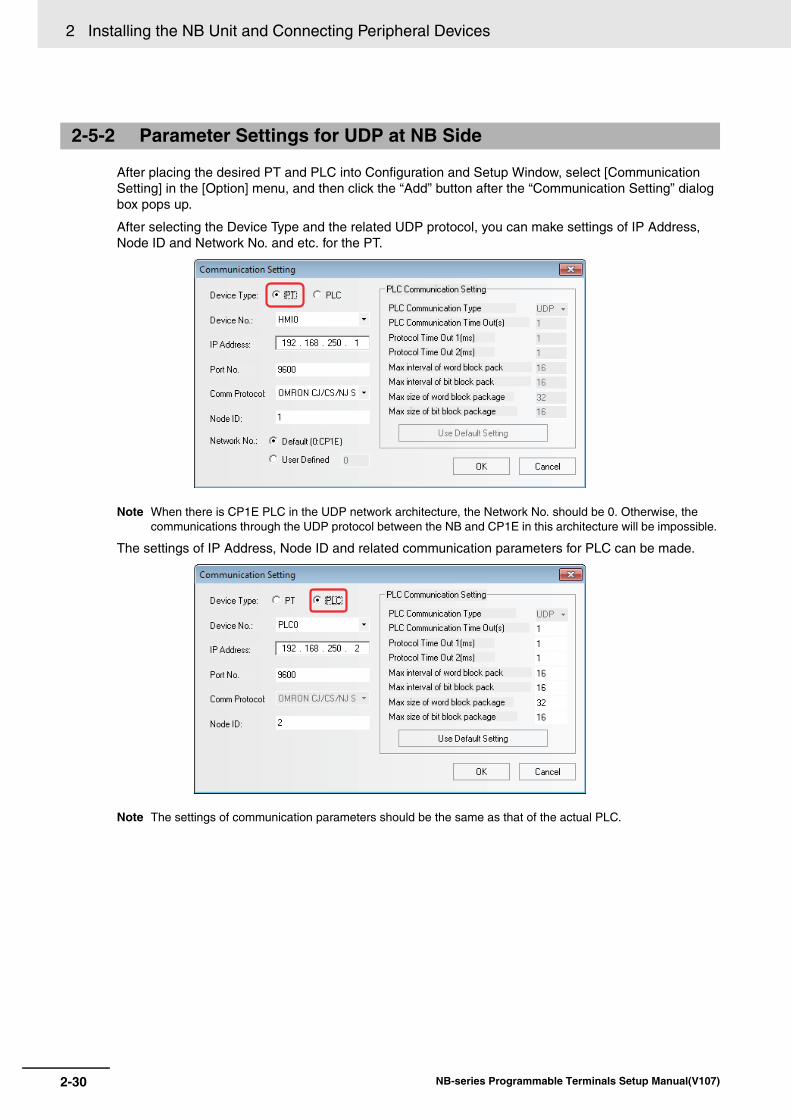
2 Installing the NB Unit and Connecting Peripheral Devices
2-30 NB-series Programmable Terminals Setup Manual(V107)
After placing the desired PT and PLC into Configuration and Setup Window, select [Communication Setting] in the [Option] menu, and then click the “Add” button after the “Communication Setting” dialog box pops up.
After selecting the Device Type and the related UDP protocol, you can make settings of IP Address, Node ID and Network No. and etc. for the PT.
Note When there is CP1E PLC in the UDP network architecture, the Network No. should be 0. Otherwise, the communications through the UDP protocol between the NB and CP1E in this architecture will be impossible.
The settings of IP Address, Node ID and related communication parameters for PLC can be made.
Note The settings of communication parameters should be the same as that of the actual PLC.
2-5-2 Parameter Settings for UDP at NB Side
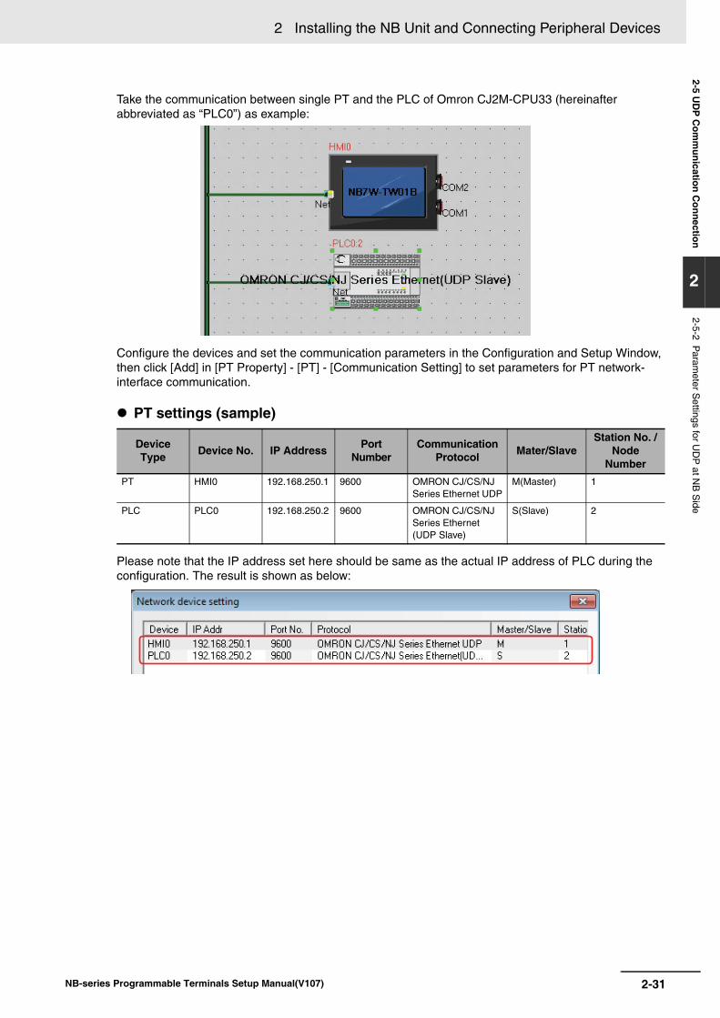
2-31
2 Installing the NB Unit and Connecting Peripheral Devices
NB-series Programmable Terminals Setup Manual(V107)
2-5 UD
P C
omm
unication Connection
2
2-5-2 Param
eter Settings for U
DP
at NB
Side
Take the communication between single PT and the PLC of Omron CJ2M-CPU33 (hereinafter abbreviated as “PLC0”) as example:
Configure the devices and set the communication parameters in the Configuration and Setup Window, then click [Add] in [PT Property] - [PT] - [Communication Setting] to set parameters for PT network-interface communication.
PT settings (sample)
Please note that the IP address set here should be same as the actual IP address of PLC during the configuration. The result is shown as below:
Device Type Device No. IP Address Port
NumberCommunication
Protocol Mater/SlaveStation No. /
Node Number
PT HMI0 192.168.250.1 9600 OMRON CJ/CS/NJ Series Ethernet UDP
M(Master) 1
PLC PLC0 192.168.250.2 9600 OMRON CJ/CS/NJ Series Ethernet (UDP Slave)
S(Slave) 2
2 Installing the NB Unit and Connecting Peripheral Devices
2-32 NB-series Programmable Terminals Setup Manual(V107)
Units that are used for Ethernet communications vary according to the type and series of OMRON PLC used.
When connecting an Ethernet Unit, check the series and type of the PLC that it will be connected to and the model of the Unit that is mounted to the PLC.
Connecting the Controllers and NB Series Units by the combinations in the table below.
For details on the hosts that can be connected to NB-series PTs via the Ethernet, refer to A-5 List of Models.
Host Settings The types of hosts that can be connected to NB-series PTs with the Ethernet and the host settings are as follows. The following settings must be set at the host.
Note 1 The max total number of registered nodes by NB-Designer in the network is 33, at least 1 NB-series PT and 1 host included.
2 If there is CP1E PLC in the actual network architecture, the Network No. must be set to 0.
3 The Node ID of 0 is equivalent to that of 1 (default).
2-5-3 Host Types and Settings of Ethernet Unit
Series name Using the built-in board Using an Ethernet Unit Ethernet UnitCS Series — CS1G/H-CPU(-V1) CS1W-ETN21
CS1G/H-CPUH
CS1D-CPUH CS1W-ETN21
CJ Series — CJ1G/H-CPUH CJ1W-ETN21
CJ1M-CPU(-ETN)
CJ1M-CPU-ETN — —
— CJ2H-CPU(-EIP) CJ1W-ETN21
CJ2M-CPU
CP1H Series — CP1H-Y CJ1W-ETN21
CP1W-CIF41CP1H-XA
CP1H-X
CP1L Series — CP1L-L14/20 CP1W-CIF41
CP1L-M30/40/60
CP1L-EL20 — —
CP1L-EM30/40
CP1E Series — CP1E-N30 CP1W-CIF41
CP1E-N40
CP1E-N60
CP1E-NA20
Item Host Settings
Number of nodes 33 (See note 1)
Network number 0 to 127 (See note 2)
UDP port number 1024 to 65535, default is 9600.
IP address 0.0.0.0 to 255.255.255.255
Subnet mask 0.0.0.0 to 255.255.255.255
Default gateway 0.0.0.0 to 255.255.255.255
Node number 0 to 254 (See note 3)
2-33
2 Installing the NB Unit and Connecting Peripheral Devices
NB-series Programmable Terminals Setup Manual(V107)
2-5 UD
P C
omm
unication Connection
2
2-5-3 Host Types and S
ettings of Ethernet U
nit
For the limitations to the Host parameters’ setting, refer to 2-5-5 Parameter Settings at Host Side (CX-Programmer).
IP Address Configuration The IP address is comprised of 32 bits of binary data, consisting of the net ID and host ID. The net ID is the address that identifies the network, and the host ID is the ID that identifies the host (node).
The IP address is divided into class A, B, and C. Select the address system from among the classes according to the network configuration.
The number of networks and hosts that can be identified depends on the class used.
The IP address is a 32-bit value divided into four 8-bit fields. Each octet is expressed as a decimal and is separated by a period.
Example: 10000010 00111010 00010001 00100000 →130.58.17.32
Additional Information
• Set the same net ID for all nodes in the same network.
• The net ID of the IP address is the value that identifies the Ethernet network (IP network segment). The net ID is not the same as the network address used for FINS communications.
• The IP network segment is the logical network unit that is configured by the nodes that have the same net ID.
IP Address Allocation The IP addresses are allocated so that they are unique for each node in the network (or between two or more networks). If two or more nodes are allocated the same IP address, the remote nodes with the same IP address will also malfunction.
IP (Internet Protocol) is a communications protocol that conforms to international standards. Therefore, to connect to the Internet, always obtain IP addresses that have been allocated by a public organization (i.e., the NIC in the country of use, such as the JPNIC in Japan). Using IP addresses that are not recognized by the NIC (JPNIC) to connect to the Internet could have unforeseen social consequences, such as causing the networks of another organizations to malfunction unexpectedly.
Class Network scope Number of hosts
Class A Small 224 - 2 max. (16,777,214 max.)
Class B Medium 216 - 2 max. (65,534 max.)
Class C Large 28 - 2 max. (254 max.)
15
Class A
Class B
Class C
Net ID (7 bits) Host ID (24 bits)
Host ID (16 bits)Net ID (14 bits)
0
0 1
0 1 1 Net ID (21 bits) Host ID (8 bits)
0 bits
0 bits
0 bits7
31
31
31
23
2 Installing the NB Unit and Connecting Peripheral Devices
2-34 NB-series Programmable Terminals Setup Manual(V107)
Local IP Address The local IP address indicates the IP address of the Ethernet Unit that is used to set the settings.
The following IP address settings are not possible.
Net ID with all bits set to 0 or 1.
Host ID with all bits set to 0 or 1.
Subnet ID with all bits set to 1.
IP addresses that begin with 127 (7F Hex) (e.g., 127.35.21.16).
Subnet Mask When more than one node is connected to the network, network operation and management can be difficult. Therefore, for convenience, configure the system by dividing a single network into multiple sub-networks. The system operates internally as multiple networks, but externally appears as a single network.
To operate a system in this way, divide the host ID field of the IP address into a subnet ID field and a host ID field.
The subnet ID field is identified by the information in the subnet mask. The subnet mask is a bit mask in which the net ID and subnet ID fields are 1 and the host ID field is 0.
Example: 11111111 11111111 11111111 00000000 → FFFFFF00
The subnet mask must have a value that is common to all nodes on the same sub-network.
Setting the subnet mask is not required if sub-networks are not used. The system recognizes subnet masks without a subnet ID field (i.e., subnet masks with net ID and host ID fields only).
The methods for setting each Unit are described next.
Note 1 Always turn OFF the power to the PLC before setting the rotary switches.
2 Create I/O tables for the CPU Unit when setting the unit number for the first time or changing settings.
CS-series Ethernet Units:
CS1W-ETN21
Setting the Front Panel Switches
Setting Unit NumbersAlways set the unit numbers so that the unit numbers of other CPU Bus Units mounted to the CPU Unit are all unique.
Use a small screwdriver to set the rotary switches, being careful not to damage them.
The factory setting is 0.
CS-series PLCs
UNITNO.
Setting range
0 to F
2-35
2 Installing the NB Unit and Connecting Peripheral Devices
NB-series Programmable Terminals Setup Manual(V107)
2-5 UD
P C
omm
unication Connection
2
2-5-3 Host Types and S
ettings of Ethernet U
nit
Setting Node Numbers
Set the upper digit using the left rotary switch and the lower digit using the right rotary switch.
The factory setting is 01. The Node ID of the rotary switch here must be consistent with that of PLC in the “Communication Setting” dialog box for the actual project created in the NB-Designer.
Setting Local IP Addresses For CS-series Ethernet Units, set the local IP address from the CX-Programmer or other Support Software for the CPU Unit. Refer to the SYSMAC CS/CJ Series Ethernet Unit Operation Manual (Cat. No. W420) for details on setting methods.
Ethernet Connectors CS1W-ETN21
This is the connector used to connect the twisted-pair cable to the Ethernet.
• Electrical characteristics: Conforms to IEEE802.3 standards.
• Connector structure: RJ45 8-pin modular connector (conforms to ISO8877).
Note 1 Always turn OFF the power to the PLC before setting the rotary switches.
2 Create I/O tables for the CPU Unit when setting the unit number for the first time or changing settings.
CJ-series Ethernet Units:
CJ1W-ETN21
Setting the Front Panel Switches
Setting Unit NumbersAlways set the unit numbers so that the unit numbers of other CPU Bus Units mounted to the same CPU Unit are all unique.
Use a small screwdriver to set the rotary switches, being careful not to damage them.
The factory setting is 0.
CJ-series PLCs
NODENO.
×161 ×160
Setting range
01 to FE (1 to 254 decimal)
1
8
Connector Pin Signal name Abbreviation Signal direction
1 Send data + TD+ Output
2 Send data - TD- Output
3 Receive data + RD+ Input
4 Not used. - -
5 Not used. - -
6 Receive data - RD- Input
7 Not used. - -
8 Not used. - -
UNITNo.
Setting range
0 to F
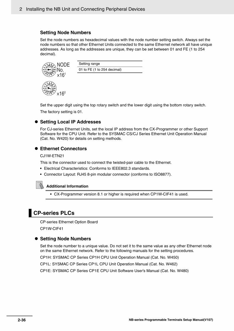
2 Installing the NB Unit and Connecting Peripheral Devices
2-36 NB-series Programmable Terminals Setup Manual(V107)
Setting Node Numbers Set the node numbers as hexadecimal values with the node number setting switch. Always set the node numbers so that other Ethernet Units connected to the same Ethernet network all have unique addresses. As long as the addresses are unique, they can be set between 01 and FE (1 to 254 decimal).
Set the upper digit using the top rotary switch and the lower digit using the bottom rotary switch.
The factory setting is 01.
Setting Local IP Addresses For CJ-series Ethernet Units, set the local IP address from the CX-Programmer or other Support Software for the CPU Unit. Refer to the SYSMAC CS/CJ Series Ethernet Unit Operation Manual (Cat. No. W420) for details on setting methods.
Ethernet Connectors CJ1W-ETN21
This is the connector used to connect the twisted-pair cable to the Ethernet.
• Electrical Characteristics: Conforms to IEEE802.3 standards.
• Connector Layout: RJ45 8-pin modular connector (conforms to ISO8877).
Additional Information
• CX-Programmer version 8.1 or higher is required when CP1W-CIF41 is used.
CP-series Ethernet Option Board
CP1W-CIF41
Setting Node Numbers Set the node number to a unique value. Do not set it to the same value as any other Ethernet node on the same Ethernet network. Refer to the following manuals for the setting procedures.
CP1H: SYSMAC CP Series CP1H CPU Unit Operation Manual (Cat. No. W450)
CP1L: SYSMAC CP Series CP1L CPU Unit Operation Manual (Cat. No. W462)
CP1E: SYSMAC CP Series CP1E CPU Unit Software User’s Manual (Cat. No. W480)
CP-series PLCs
NODENo.×161
×160
Setting range
01 to FE (1 to 254 decimal)
2-37
2 Installing the NB Unit and Connecting Peripheral Devices
NB-series Programmable Terminals Setup Manual(V107)
2-5 UD
P C
omm
unication Connection
2
2-5-3 Host Types and S
ettings of Ethernet U
nit
Setting Local IP Addresses Use a Web browser to set the local IP address of the CP-series Ethernet Option Board.
Refer to the following manuals for the setting procedures.
CP1H: SYSMAC CP Series CP1H CPU Unit Operation Manual (Cat. No. W450)
CP1L: SYSMAC CP Series CP1L CPU Unit Operation Manual (Cat. No. W462)
CP1E: SYSMAC CP Series CP1E CPU Unit Software User’s Manual (Cat. No. W480)
Ethernet ConnectorCP1W-CIF41
This is the connector used to connect the twisted-pair cable to the Ethernet.
• Electrical Characteristics: Conform to the IEEE 802.3 standard.
• Connector Layout: RJ45 8-pin modular connector (conforms to ISO8877.)
Setting Node Numbers Set the node number to a unique value from the CX-Programmer or other Support Software. Do not set it to the same value as any other Ethernet node on the same Ethernet network. Refer to the following manuals for the setting procedures.
CP1L-EL/EM: SYSMAC CP Series CP1L-EL/EM CPU Unit Operation Manual (Cat. No. W516)
Setting Local IP Addresses Set the local IP address from the CX-Programmer or other Support Software for the CP1L-EL/EM series CPU Unit.
Refer to the following manuals for the setting procedures.
CP1L-EL/EM: SYSMAC CP Series CP1L-EL/EM CPU Unit Operation Manual (Cat. No. W516)
Ethernet ConnectorCP1L-ETN21
This is the connector used to connect the twisted-pair cable to the Ethernet.
• Electrical Characteristics: Conform to the IEEE 802.3 standard.
• Connector Layout: RJ45 8-pin modular connector (conforms to ISO8877.)
CP1L-EL/EM
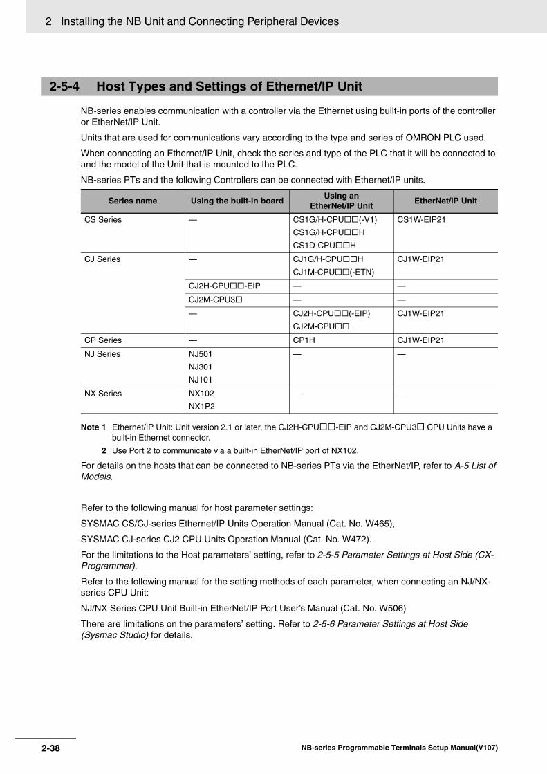
2 Installing the NB Unit and Connecting Peripheral Devices
2-38 NB-series Programmable Terminals Setup Manual(V107)
NB-series enables communication with a controller via the Ethernet using built-in ports of the controller or EtherNet/IP Unit.
Units that are used for communications vary according to the type and series of OMRON PLC used.
When connecting an Ethernet/IP Unit, check the series and type of the PLC that it will be connected to and the model of the Unit that is mounted to the PLC.
NB-series PTs and the following Controllers can be connected with Ethernet/IP units.
Note 1 Ethernet/IP Unit: Unit version 2.1 or later, the CJ2H-CPU-EIP and CJ2M-CPU3 CPU Units have a built-in Ethernet connector.
2 Use Port 2 to communicate via a built-in EtherNet/IP port of NX102.
For details on the hosts that can be connected to NB-series PTs via the EtherNet/IP, refer to A-5 List of Models.
Refer to the following manual for host parameter settings:
SYSMAC CS/CJ-series Ethernet/IP Units Operation Manual (Cat. No. W465),
SYSMAC CJ-series CJ2 CPU Units Operation Manual (Cat. No. W472).
For the limitations to the Host parameters’ setting, refer to 2-5-5 Parameter Settings at Host Side (CX-Programmer).
Refer to the following manual for the setting methods of each parameter, when connecting an NJ/NX-series CPU Unit:
NJ/NX Series CPU Unit Built-in EtherNet/IP Port User’s Manual (Cat. No. W506)
There are limitations on the parameters’ setting. Refer to 2-5-6 Parameter Settings at Host Side (Sysmac Studio) for details.
2-5-4 Host Types and Settings of Ethernet/IP Unit
Series name Using the built-in board Using an EtherNet/IP Unit EtherNet/IP Unit
CS Series — CS1G/H-CPU(-V1)
CS1G/H-CPUH
CS1D-CPUH
CS1W-EIP21
CJ Series — CJ1G/H-CPUH
CJ1M-CPU(-ETN)
CJ1W-EIP21
CJ2H-CPU-EIP — —
CJ2M-CPU3 — —
— CJ2H-CPU(-EIP)
CJ2M-CPU
CJ1W-EIP21
CP Series — CP1H CJ1W-EIP21
NJ Series NJ501
NJ301
NJ101
— —
NX Series NX102
NX1P2
— —
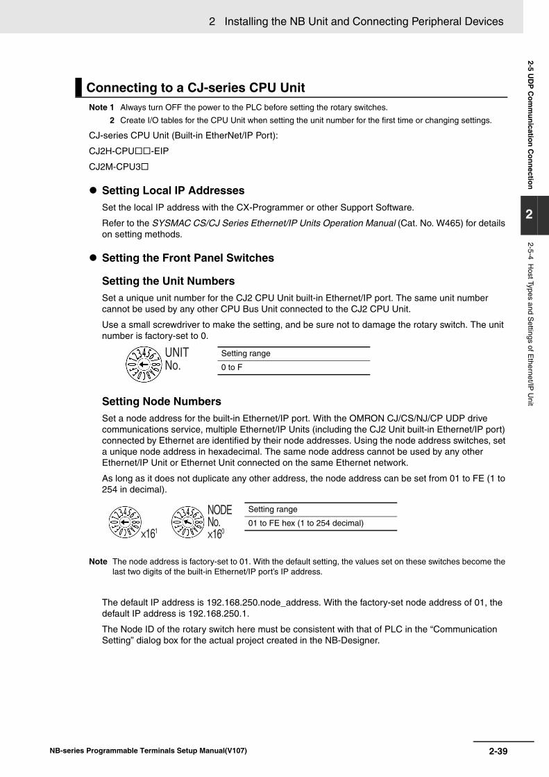
2-39
2 Installing the NB Unit and Connecting Peripheral Devices
NB-series Programmable Terminals Setup Manual(V107)
2-5 UD
P C
omm
unication Connection
2
2-5-4 Host Types and S
ettings of Ethernet/IP
Unit
Note 1 Always turn OFF the power to the PLC before setting the rotary switches.
2 Create I/O tables for the CPU Unit when setting the unit number for the first time or changing settings.
CJ-series CPU Unit (Built-in EtherNet/IP Port):
CJ2H-CPU-EIP
CJ2M-CPU3
Setting Local IP AddressesSet the local IP address with the CX-Programmer or other Support Software.
Refer to the SYSMAC CS/CJ Series Ethernet/IP Units Operation Manual (Cat. No. W465) for details on setting methods.
Setting the Front Panel Switches
Setting the Unit NumbersSet a unique unit number for the CJ2 CPU Unit built-in Ethernet/IP port. The same unit number cannot be used by any other CPU Bus Unit connected to the CJ2 CPU Unit.
Use a small screwdriver to make the setting, and be sure not to damage the rotary switch. The unit number is factory-set to 0.
Setting Node NumbersSet a node address for the built-in Ethernet/IP port. With the OMRON CJ/CS/NJ/CP UDP drive communications service, multiple Ethernet/IP Units (including the CJ2 Unit built-in Ethernet/IP port) connected by Ethernet are identified by their node addresses. Using the node address switches, set a unique node address in hexadecimal. The same node address cannot be used by any other Ethernet/IP Unit or Ethernet Unit connected on the same Ethernet network.
As long as it does not duplicate any other address, the node address can be set from 01 to FE (1 to 254 in decimal).
Note The node address is factory-set to 01. With the default setting, the values set on these switches become the last two digits of the built-in Ethernet/IP port’s IP address.
The default IP address is 192.168.250.node_address. With the factory-set node address of 01, the default IP address is 192.168.250.1.
The Node ID of the rotary switch here must be consistent with that of PLC in the “Communication Setting” dialog box for the actual project created in the NB-Designer.
Connecting to a CJ-series CPU Unit
UNITNo.
Setting range
0 to F
NODENo.×160×161
Setting range
01 to FE hex (1 to 254 decimal)
2 Installing the NB Unit and Connecting Peripheral Devices
2-40 NB-series Programmable Terminals Setup Manual(V107)
Ethernet Connectors This is the connector used to connect the twisted-pair cable to the Ethernet.
• Electrical Characteristics: Conforms to IEEE802.3 standards.
• Connector Layout: RJ45 8-pin modular connector (conforms to ISO 8877).
NJ-series CPU Unit (Built-in EtherNet/IP Port)
NJ501
NJ301
NJ101
NX-series CPU Unit (Built-in EtherNet/IP Port)
NX102 *1
NX1P2*1 Use Port 2 to communicate via a built-in EtherNet/IP port of NX102.
Setting IP AddressesSet the IP address of the NJ/NX unit with the Sysmac Studio.
Refer to the Sysmac Studio Version 1 Operation Manual (Cat. No. W504) and the NJ/NX-series CPU Unit Built-in EtherNet/IP Port User’s Manual (Cat. No. W501) for details on setting methods.
Ethernet Connectors This is the connector used to connect the twisted-pair cable to the Ethernet.
• Electrical Characteristics: Conforms to IEEE802.3 standards.
• Connector Layout: RJ45 8-pin modular connector (conforms to ISO 8877).
• Memory Settings for CJ-series Units Refer to the description of " When connecting to a NX Series Serial Communication Board" in 2-4-3 Settings for each Unit.
Connecting to a NJ/NX-series CPU Unit
1
8
Connector Pin Signal name Abbreviation Signal direction
1 Send data + TD+ Output
2 Send data - TD- Output
3 Receive data + RD+ Input
4 Not used. - -
5 Not used. - -
6 Receive data - RD- Input
7 Not used. - -
8 Not used. - -
1
8
Connector Pin Signal name Abbreviation Signal direction
1 Send data TD+ Output
2 Send data - TD- Output
3 Receive data + RD+ Input
4 Not used. - -
5 Not used. - -
6 Receive data - RD- Input
7 Not used. - -
8 Not used. - -
2-41
2 Installing the NB Unit and Connecting Peripheral Devices
NB-series Programmable Terminals Setup Manual(V107)
2-5 UD
P C
omm
unication Connection
2
2-5-4 Host Types and S
ettings of Ethernet/IP
Unit
Note 1 Always turn OFF the power to the PLC before setting the rotary switches.
2 Create I/O tables for the CPU Unit when setting the unit number for the first time or changing settings.
CS-series EtherNet/IP Unit:
CS1W-EIP21
Setting the Front Panel Switches
Setting Unit Numbers Always set the unit numbers so that the unit numbers of other CPU Bus Units mounted to the same CPU Unit are all unique.
Use a small screwdriver to set the rotary switches, being careful not to damage them.
The factory setting is 0.
Setting Node Numbers Use the node address switches to set the node address to a unique hexadecimal value. Do not set it to the same value as any other Ethernet/IP Unit or built-in port on the same Ethernet/IP network. As long as it does not duplicate the address of any other Ethernet/IP Unit or built-in port, the node address can be set from 01 to FE hex (1 to 254 decimal).
Set the upper digit using the left rotary switch and the lower digit using the right rotary switch.
The factory setting is 01. The Node ID of the rotary switch here must be consistent with that of PLC in the “Communication Setting” dialog box for the actual project created in the NB-Designer.
Setting Local IP Addresses Set the local IP address with the CX-Programmer or other Support Software.
For the setting procedure, refer to the SYSMAC CS/CJ-series Ethernet/IP Units Operation Manual (Cat. No. W465).
Ethernet Connectors This is the connector used to connect the twisted-pair cable to the Ethernet.
• Electrical Characteristics: Conforms to IEEE802.3 standards.
• Connector Layout: RJ45 8-pin modular connector (conforms to ISO 8877).
Connecting to a CS-series Ethernet/IP Unit
UNITNO.
Setting range
0 to F
NODENO.
×161 ×160
Setting range
01 to FE (1 to 254 decimal)
2 Installing the NB Unit and Connecting Peripheral Devices
2-42 NB-series Programmable Terminals Setup Manual(V107)
Note 1 Always turn OFF the power to the PLC before setting the rotary switches.
2 Create I/O tables for the CPU Unit when setting the unit number for the first time or changing settings.
CJ-series EtherNet/IP Unit:
CJ1W-EIP21
Setting the Front Panel Switches
Setting Unit Numbers Always set the unit numbers so that the unit numbers of other CPU Bus Units mounted to the same CPU Unit are all unique.
Use a small screwdriver to set the rotary switches, being careful not to damage them.
The factory setting is 0.
Setting Node Numbers Use the node address switches to set the node address to a unique hexadecimal value. Do not set it to the same value as any other Ethernet/IP Unit or built-in port on the same Ethernet/IP network. As long as it does not duplicate the address of any other Ethernet/IP Unit or built-in port, the node address can be set from 01 to FE hex (1 to 254 decimal).
Set the upper digit using the left rotary switch and the lower digit using the right rotary switch.
The factory setting is 01. The Node ID of the rotary switch here must be consistent with that of PLC in the “Communication Setting” dialog box for the actual project created in the NB-Designer.
Setting Local IP Addresses Set the local IP address with the CX-Programmer or other computer support software. Refer to the Ethernet/IP Unit Operation Manual (Cat. No. W465) for details on setting methods.
Ethernet Connectors This is the connector used to connect the twisted-pair cable to the Ethernet.
• Electrical Characteristics: Conforms to IEEE802.3 standards.
• Connector Layout: RJ45 8-pin modular connector (conforms to ISO8877).
Connecting to a CJ-series Ethernet/IP Unit
UNITNo.
Setting range
0 to F
NODENo.×160×161
Setting range
01 to FE (1 to 254 decimal)
2-43
2 Installing the NB Unit and Connecting Peripheral Devices
NB-series Programmable Terminals Setup Manual(V107)
2-5 UD
P C
omm
unication Connection
2
2-5-5 Param
eter Settings at H
ost Side (C
X-P
rogramm
er)
Because the port number of NB is dynamic, the user doesn’t need to set it during the communications through the UDP protocol. But user needs to set the UDP parameters at the Host side of OMRON PLC in the CX-Programmer referring to the following limitations.
Take the settings of CJ1W-ETN21 as example:
The limitations are as follows:
1. Do not check the “Auto (Static)” option in the [Conversion] check box.
2. Do not check the “Destination IP is Not changed dyn:” in the [FINS/UDP Option] check box.
3. Only the “Destination IP is changed dynamic:” can be checked in the [FINS/UDP Option] check box after either of “Auto (dynamic)”, “Combined” and “IP address table” is checked in the [Conversion] check box. When insert the IP address into the [IP Address Table] after the “IP address table” or “Combined” is checked, do not make the Node ID of NB into it. *1
*1 If the Node ID of NB is placed into the [IP Address Table], the system will require the NB to use the same port with the PLC, and “PLC response error” information will appear on NB.
The prompts for possible errors occurred to NB when UDP protocol is adopted are described as follows:
“PLC Response Error”: Response to the abnormal information caused by the Read/Write command to PLC.
“PLC No Response: xx-xx-x”: No response is made by PLC and xx-xx-x represents PT No.-Node ID of PLC-Port Number.
2-5-5 Parameter Settings at Host Side (CX-Programmer)
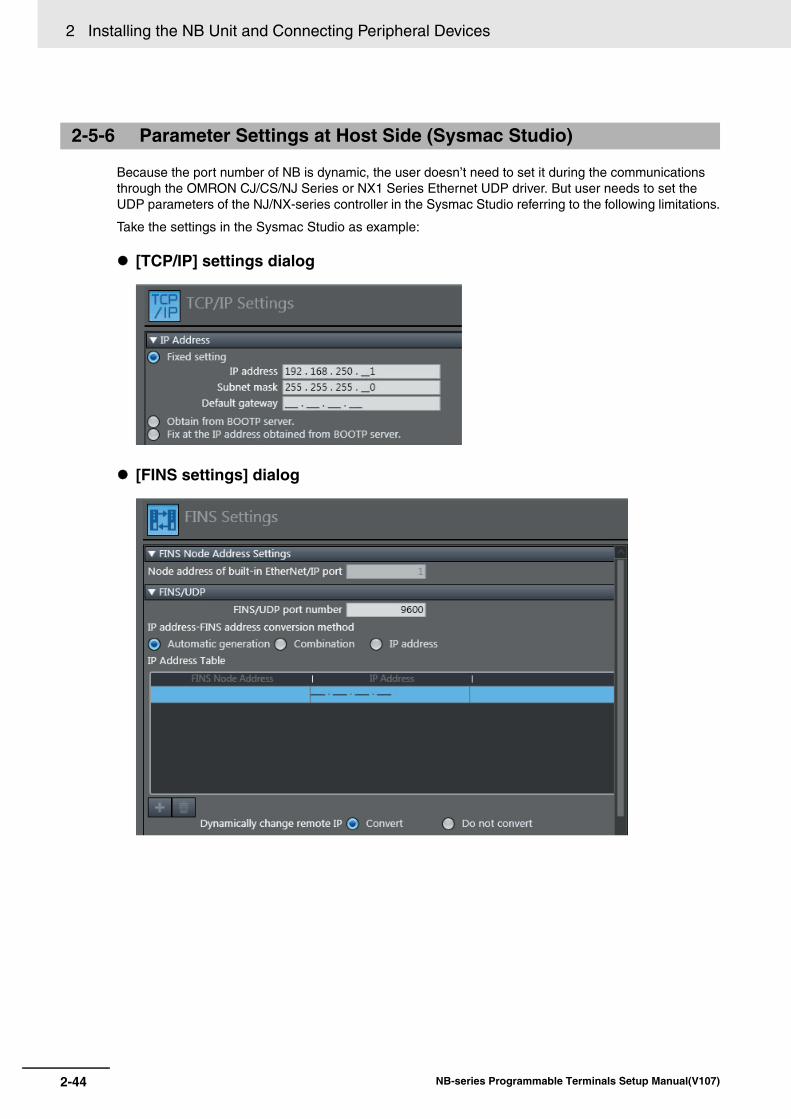
2 Installing the NB Unit and Connecting Peripheral Devices
2-44 NB-series Programmable Terminals Setup Manual(V107)
Because the port number of NB is dynamic, the user doesn’t need to set it during the communications through the OMRON CJ/CS/NJ Series or NX1 Series Ethernet UDP driver. But user needs to set the UDP parameters of the NJ/NX-series controller in the Sysmac Studio referring to the following limitations.
Take the settings in the Sysmac Studio as example:
[TCP/IP] settings dialog
[FINS settings] dialog
2-5-6 Parameter Settings at Host Side (Sysmac Studio)
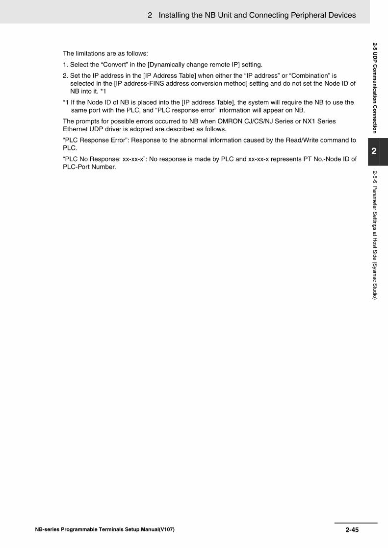
2-45
2 Installing the NB Unit and Connecting Peripheral Devices
NB-series Programmable Terminals Setup Manual(V107)
2-5 UD
P C
omm
unication Connection
2
2-5-6 Param
eter Settings at H
ost Side (S
ysmac S
tudio)
The limitations are as follows:
1. Select the “Convert” in the [Dynamically change remote IP] setting.
2. Set the IP address in the [IP Address Table] when either the “IP address” or “Combination” is selected in the [IP address-FINS address conversion method] setting and do not set the Node ID of NB into it. *1
*1 If the Node ID of NB is placed into the [IP address Table], the system will require the NB to use the same port with the PLC, and “PLC response error” information will appear on NB.
The prompts for possible errors occurred to NB when OMRON CJ/CS/NJ Series or NX1 Series Ethernet UDP driver is adopted are described as follows.
“PLC Response Error”: Response to the abnormal information caused by the Read/Write command to PLC.
“PLC No Response: xx-xx-x”: No response is made by PLC and xx-xx-x represents PT No.-Node ID of PLC-Port Number.
2 Installing the NB Unit and Connecting Peripheral Devices
2-46 NB-series Programmable Terminals Setup Manual(V107)
3-1NB-series Programmable Terminals Setup Manual(V107)
3This section describes the System Setting Mode
3-1 Display Method of System Setting Mode . . . . . . . . . . . . . . . . . . . . . . . . . . . 3-2
3-2 Functions of System Setting Mode . . . . . . . . . . . . . . . . . . . . . . . . . . . . . . . 3-3
System Setting Mode
3 System Setting Mode
3-2 NB-series Programmable Terminals Setup Manual(V107)
3-1 Display Method of System Setting Mode
Enter the System Setting Mode following the procedures below.
(1) Set both the DIP switches SW1 and SW2 on the back side to ON.
(2) Press the Reset switch, restart the NB Unit, and then it enters into the System Setting Mode.
3-3
3 System Setting Mode
NB-series Programmable Terminals Setup Manual(V107)
3-2 Functions of System
Setting M
ode
3
3-2 Functions of System Setting Mode
The following items can be set in System Setting Mode:
(1) Time calibration: check whether the year, month, day, hour, minute and second are the current time values, and if not, rectify them manually.
(2) IP Address (Only supported by NB-TW01B): Sets the IP address for PT.
Port (Only supported by NB-TW01B): Sets the port number.
Subnet Mask (Only supported by NB-TW01B): Sets the subnet mask.
Gateway (Only supported by NB-TW01B): Sets the gateway.
(3) Startup Window No.: the window displayed after launching the NB Unit. The default is window 0.
(4) Backlight Saver Time: time to activate the screen saver, and the Unit is minute. The default is 10 minutes. The screen saver is not brought into effect when the set value is 0.
(5) Mute Enabled/Disabled: ON/OFF of the buzzer.
(6) Brightness Up/Down: with this, brightness of the screen can be adjusted, bringing the screen to its best visual effect.
(7) Export/Import (Only supported by NB-TW01B):
USBPT: Uploads the user project file (.pkg) required by the PT operation to the USB memory. And the upload password is required during the export. If the upload password is not set, it needs to use the default password of 888888.
USBPT: Downloads the user project file (.pkg) in USB memory to PT.
RCPPT: Uploads the recipe data file (.rcp) in PT to the USB memory.
RCPPT: Downloads the recipe data file (.rcp) in USB memory to PT.
(8) Enable Printer Function: refer to Section 7 Pictbridge Printing in NB-Designer Operation Manual for details.
The System Setting Mode screen of the NB7W-TW01B is as follows:
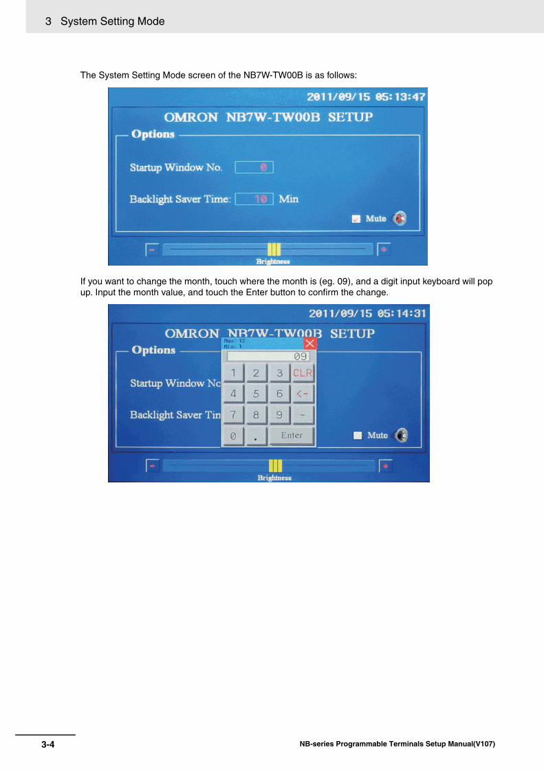
3 System Setting Mode
3-4 NB-series Programmable Terminals Setup Manual(V107)
The System Setting Mode screen of the NB7W-TW00B is as follows:
If you want to change the month, touch where the month is (eg. 09), and a digit input keyboard will pop up. Input the month value, and touch the Enter button to confirm the change.
4-1NB-series Programmable Terminals Setup Manual(V107)
4This section describes the Calibrate Mode.
4-1 Display Method of Calibrate Mode . . . . . . . . . . . . . . . . . . . . . . . . . . . . . . . . 4-2
4-2 Functions of Calibrate Mode . . . . . . . . . . . . . . . . . . . . . . . . . . . . . . . . . . . . . 4-2
4-3 On-line Touch-control Calibration Function . . . . . . . . . . . . . . . . . . . . . . . . 4-2
Calibrate Mode
4 Calibrate Mode
4-2 NB-series Programmable Terminals Setup Manual(V107)
4-1 Display Method of Calibrate Mode
There are 2 methods for entering into Calibrate Mode.
(1) Set the DIP switches SW1 and SW2 on the back side respectively to OFF and ON.
Press the Reset switch, restart the NB Unit, and then it enters into the Calibrate Mode.
(2) Place a “Function Key” component in the window, and set its function to “Touch Calibration”.
Touch the “Function Key” component in the window to start Calibrate Mode.
4-2 Functions of Calibrate Mode
Procedures to carry out Calibrate Mode:
Track and touch the “+” displayed on the screen and you will hear a “touch”. Carry on with this, until the “+” disappear followed by a “TP Adjust Success!” turning up on the screen. Set both of the DIP switches SW1 and SW2 to OFF, press the Reset switch again.
4-3 On-line Touch-control Calibration Function
Besides using the DIP switches, Touch-control Calibration can also be achieved with a function key while the software is running, thus sparing the time of equipment adjustment and the trouble of opening the control panel. For details, refer to 3-7-2 Function Key in the NB-Designer Operation Manual.
A-1
pp
NB-series Programmable Terminals Setup Manual(V107)
AppA-1 Specifications . . . . . . . . . . . . . . . . . . . . . . . . . . . . . . . . . . . . . . . . . . . . . . . . . A-2
A-1-1 General Specifications . . . . . . . . . . . . . . . . . . . . . . . . . . . . . . . . . . . . . . . . . . . A-2A-1-2 Performance Specifications . . . . . . . . . . . . . . . . . . . . . . . . . . . . . . . . . . . . . . . A-2
A-1-3 Communication Specifications . . . . . . . . . . . . . . . . . . . . . . . . . . . . . . . . . . . . . A-4
A-2 External Dimensions . . . . . . . . . . . . . . . . . . . . . . . . . . . . . . . . . . . . . . . . . . . A-5
A-3 RS-422A/485 Connections . . . . . . . . . . . . . . . . . . . . . . . . . . . . . . . . . . . . . . . A-7A-3-1 Grounding and Shielding of the Cables . . . . . . . . . . . . . . . . . . . . . . . . . . . . . . A-7
A-4 Fabrication of the Connection Cable . . . . . . . . . . . . . . . . . . . . . . . . . . . . . . A-9A-4-1 Cable Processing . . . . . . . . . . . . . . . . . . . . . . . . . . . . . . . . . . . . . . . . . . . . . . . A-9
A-4-2 Soldering . . . . . . . . . . . . . . . . . . . . . . . . . . . . . . . . . . . . . . . . . . . . . . . . . . . . A-10
A-4-3 Shield Assembly . . . . . . . . . . . . . . . . . . . . . . . . . . . . . . . . . . . . . . . . . . . . . . A-10A-4-4 Method for Fabricating the Cable for Connection to OMRON PLC . . . . . . . . A-11
A-4-5 Method for fabricating the cable for connection to PC . . . . . . . . . . . . . . . . . . A-14
A-5 List of Models . . . . . . . . . . . . . . . . . . . . . . . . . . . . . . . . . . . . . . . . . . . . . . . . A-15
A-6 List of Options . . . . . . . . . . . . . . . . . . . . . . . . . . . . . . . . . . . . . . . . . . . . . . . A-19
Appendices
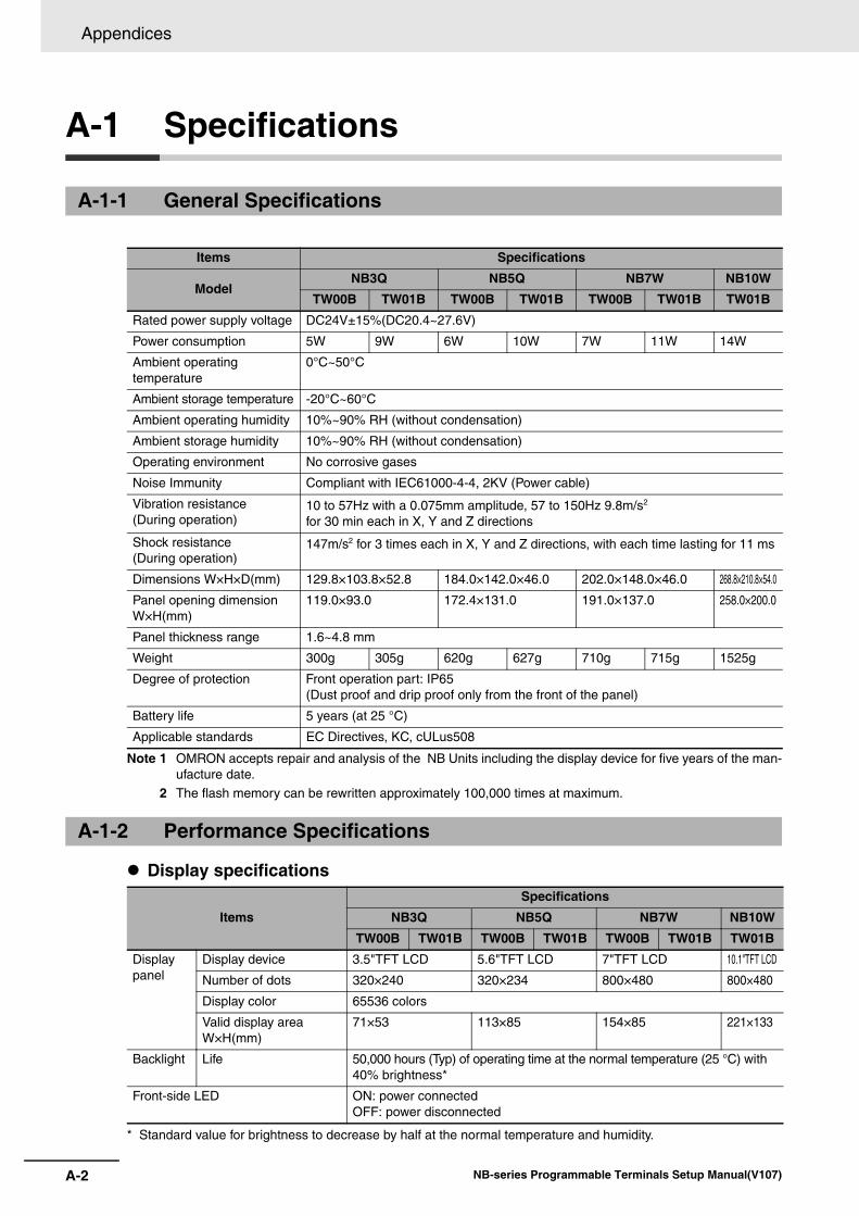
Appendices
A-2 NB-series Programmable Terminals Setup Manual(V107)
A-1 Specifications
Note 1 OMRON accepts repair and analysis of the NB Units including the display device for five years of the man-ufacture date.
2 The flash memory can be rewritten approximately 100,000 times at maximum.
Display specifications
* Standard value for brightness to decrease by half at the normal temperature and humidity.
A-1-1 General Specifications
Items Specifications
ModelNB3Q NB5Q NB7W NB10W
TW00B TW01B TW00B TW01B TW00B TW01B TW01BRated power supply voltage DC24V±15%(DC20.4~27.6V)
Power consumption 5W 9W 6W 10W 7W 11W 14W
Ambient operating temperature
0°C~50°C
Ambient storage temperature -20°C~60°C
Ambient operating humidity 10%~90% RH (without condensation)
Ambient storage humidity 10%~90% RH (without condensation)
Operating environment No corrosive gases
Noise Immunity Compliant with IEC61000-4-4, 2KV (Power cable)
Vibration resistance (During operation)
10 to 57Hz with a 0.075mm amplitude, 57 to 150Hz 9.8m/s2
for 30 min each in X, Y and Z directions
Shock resistance (During operation)
147m/s2 for 3 times each in X, Y and Z directions, with each time lasting for 11 ms
Dimensions W×H×D(mm) 129.8×103.8×52.8 184.0×142.0×46.0 202.0×148.0×46.0 268.8×210.8×54.0
Panel opening dimension W×H(mm)
119.0×93.0 172.4×131.0 191.0×137.0 258.0×200.0
Panel thickness range 1.6~4.8 mm
Weight 300g 305g 620g 627g 710g 715g 1525g
Degree of protection Front operation part: IP65(Dust proof and drip proof only from the front of the panel)
Battery life 5 years (at 25 °C)
Applicable standards EC Directives, KC, cULus508
A-1-2 Performance Specifications
ItemsSpecifications
NB3Q NB5Q NB7W NB10WTW00B TW01B TW00B TW01B TW00B TW01B TW01B
Display panel
Display device 3.5"TFT LCD 5.6"TFT LCD 7"TFT LCD 10.1"TFT LCD
Number of dots 320×240 320×234 800×480 800×480
Display color 65536 colors
Valid display area W×H(mm)
71×53 113×85 154×85 221×133
Backlight Life 50,000 hours (Typ) of operating time at the normal temperature (25 °C) with 40% brightness*
Front-side LED ON: power connectedOFF: power disconnected
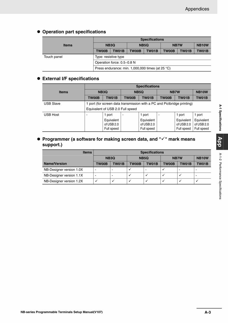
A-3
Appendices
NB-series Programmable Terminals Setup Manual(V107)
A-1 S
pecificationsA
ppA
-1-2 Perform
ance Specifications
Operation part specifications
External I/F specifications
Programmer (a software for making screen data, and "" mark means support.)
Items
Specifications
NB3Q NB5Q NB7W NB10W
TW00B TW01B TW00B TW01B TW00B TW01B TW01B
Touch panel Type: resistive type
Operation force: 0.5~0.8 N
Press endurance: min. 1,000,000 times (at 25 °C)
Items
Specifications
NB3Q NB5Q NB7W NB10W
TW00B TW01B TW00B TW01B TW00B TW01B TW01B
USB Slave 1 port (for screen data transmission with a PC and Pictbridge printing)
Equivalent of USB 2.0 Full speed
USB Host - 1 port
Equivalent of USB 2.0 Full speed
- 1 port
Equivalent of USB 2.0 Full speed
- 1 port
Equivalent of USB 2.0 Full speed
1 port
Equivalent of USB 2.0 Full speed
Items Specifications
Name/VersionNB3Q NB5Q NB7W NB10W
TW00B TW01B TW00B TW01B TW00B TW01B TW01B
NB-Designer version 1.0X - - - - -
NB-Designer version 1.1X - - -
NB-Designer version 1.2X
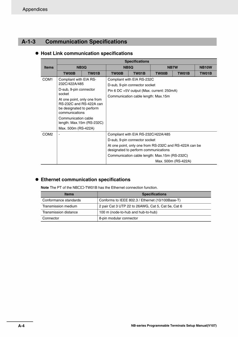
Appendices
A-4 NB-series Programmable Terminals Setup Manual(V107)
Host Link communication specifications
Ethernet communication specificationsNote The PT of the NB-TW01B has the Ethernet connection function.
A-1-3 Communication Specifications
Items
Specifications
NB3Q NB5Q NB7W NB10W
TW00B TW01B TW00B TW01B TW00B TW01B TW01B
COM1 Compliant with EIA RS-232C/422A/485
D-sub, 9-pin connector socket
At one point, only one from RS-232C and RS-422A can be designated to perform communications
Communication cable length: Max.15m (RS-232C)
Max. 500m (RS-422A)
Compliant with EIA RS-232C
D-sub, 9-pin connector socket
Pin 6 DC +5V output (Max. current: 250mA)
Communication cable length: Max.15m
COM2 - Compliant with EIA RS-232C/422A/485
D-sub, 9-pin connector socket
At one point, only one from RS-232C and RS-422A can be designated to perform communications
Communication cable length: Max.15m (RS-232C)
Max. 500m (RS-422A)
Items Specifications
Conformance standards Conforms to IEEE 802.3 / Ethernet (10/100Base-T)
Transmission medium 2 pair Cat 3 UTP 22 to 26AWG, Cat 5, Cat 5e, Cat 6
Transmission distance 100 m (node-to-hub and hub-to-hub)
Connector 8-pin modular connector
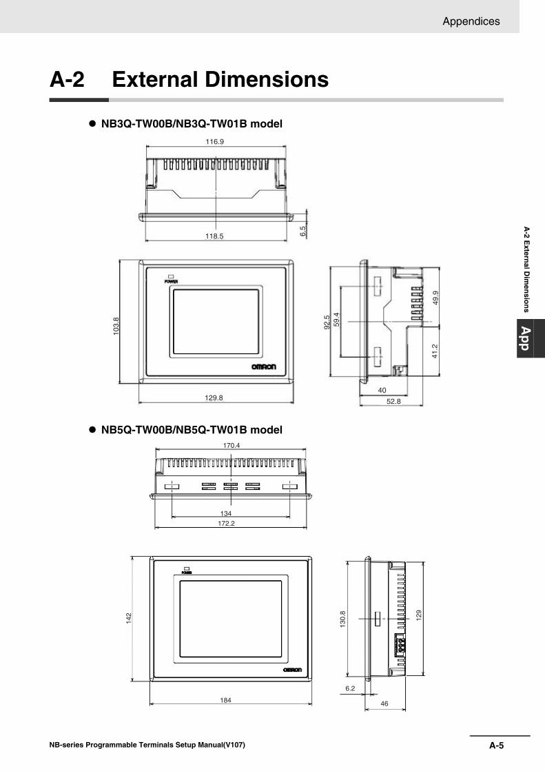
A-5
Appendices
NB-series Programmable Terminals Setup Manual(V107)
A-2 E
xternal Dim
ensionsA
pp
A-2 External Dimensions
NB3Q-TW00B/NB3Q-TW01B model
NB5Q-TW00B/NB5Q-TW01B model
116.9
118.5
103.
8
92.5
41.2
49.9
59.4
6.5
129.840
52.8
170.4
134
172.2
142
184
130.
8
129
6.2
46
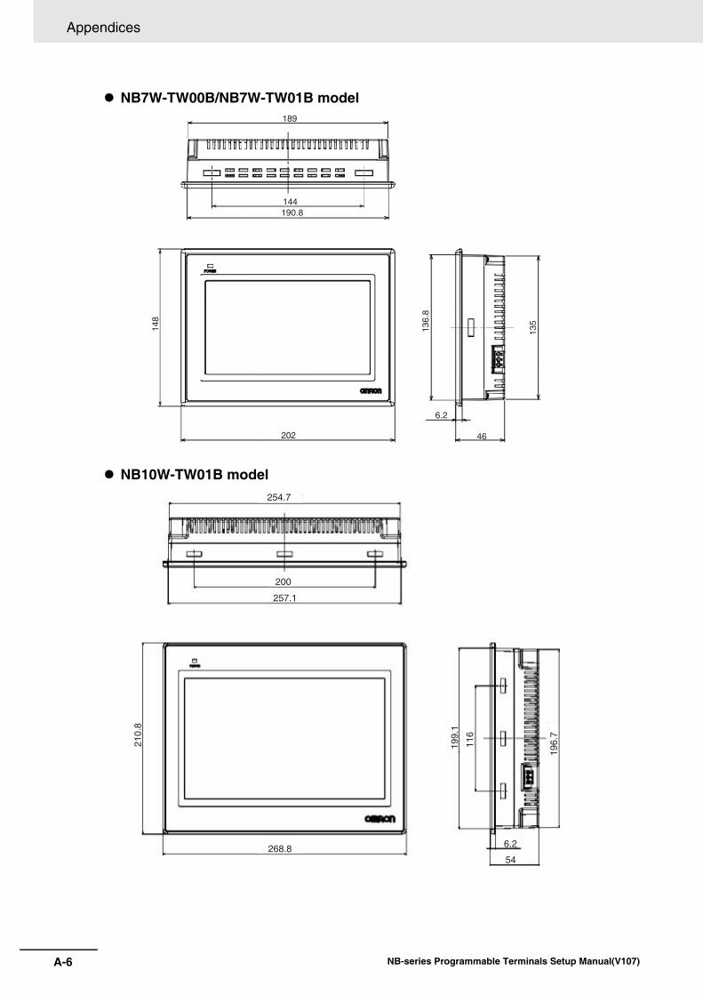
Appendices
A-6 NB-series Programmable Terminals Setup Manual(V107)
NB7W-TW00B/NB7W-TW01B model
NB10W-TW01B model
189
144190.8
148
20213
6.8
135
6.2
46
254.7
200
210.
8
199.
1
196.
7
116
257.1
268.8 6.2
54
A-7
Appendices
NB-series Programmable Terminals Setup Manual(V107)
A-3 R
S-422A
/485 Connections
App
A-3-1 G
rounding and Shielding of the C
ables
A-3 RS-422A/485 Connections
When performing communications using RS-422A/485, carry out the connections, shielding and grounding as follows:
Grounding wiring
The NB Unit has a functional grounding terminal (FG: ).
(1) Generally, make the grounding according to Fig. (a).
• Connect the grounding terminals (GR) of the devices and the functional grounding terminal
( ), at only one point make a D-type grounding (Max. grounding resistance 100Ω).
• Short-circuit the LG terminal and GR terminal of the PLC.
• Use a cable with a minimum of 2 mm2 for the grounding cable.
• For details about the connection methods, refer to the related communication Unit manuals.
(2) As shown in Fig. (b), when the NB Unit, and noise source equipments such as motors and inverters, etc. are installed on the same panel, do not ground the NB Unit’s functional
grounding terminal ( ).
Shielding of RS-422A/485 CablesBe sure to shield the RS-422A/485 cables. Connect the grounding terminals (GR) of the devices and
the functional grounding terminals ( ), at only one point make a D-type grounding (Max. grounding
resistance 100Ω), carry out a single-end shielding according to Fig. (a).
If grounding is not done to the functional grounding terminal ( ) of the NB Unit, shield both ends as
shown in Fig. (b).
Note In order to avoid malfunctions caused by interferences, shield the cables properly.
A-3-1 Grounding and Shielding of the Cables
Appendices
A-8 NB-series Programmable Terminals Setup Manual(V107)
Note: When connecting an NB Unit with an Omron PLC using the Host Link method, only 1:1 communication issupported. Do not connect multiple PLCs with an NB Unit.
CPU Rack CPU Rack
RS-422A/485one end shielded wire
RS-422A/485both ends shielded wire
PT
FG
PT
PT
PT
FG
FG
FG
FG
FG
PT
PT
Signal line Signal line
CPU Unit or Communi-cation Unit
Power supply Unit
CPU Unit or Communi-cation Unit
Power supply Unit
LGGR
LGGR
Figure(b)Figure(a)
A-9
Appendices
NB-series Programmable Terminals Setup Manual(V107)
A-4 Fabrication of the C
onnection Cable
App
A-4-1 C
able Processing
A-4 Fabrication of the Connection Cable
Fabricate the connection cable following the procedures below.
1 Cut the cable to the required length.
2 Use a tool like a razor, etc. to cut off the ethylene peel of the cable. Be care not to damage the
shielding layer (for grouping purpose)
3 Use a pair of scissors to snip off the shielding layer.
4 Bring out the core of each wire using a wire stripper.
5 Fold back the shielding layer.
6 Wrap the folded part of the shielding layer with aluminum foil tape.
A-4-1 Cable Processing
40 (RS-232C)25 (RS-422A/RS485)
Aluminum foil tape(Unit mm)
5
10
1)
2)
3)
4)
5)
6)
Appendices
A-10 NB-series Programmable Terminals Setup Manual(V107)
1 Sheathe each wire with a heat shrinkable tube.
2 Place some standby soldering tin on each wire and each pin of the connector.
3 Solder each wire and each pin of the connector.
4 Pull the heat shrinkable tubes back to the soldering parts, heat them with a heat shrinking gun
to make them shrink.
Assemble the connector shield as shown below.
A-4-2 Soldering
A-4-3 Shield Assembly
Solderingiron
1mm
Heat-shrinkable tube Inside diameter:1.5 Length=10
Heat-shrinkable tube
The end connected to the connector
The end not connected to the connector
Aluminum Foil Tape
A-11
Appendices
NB-series Programmable Terminals Setup Manual(V107)
A-4 Fabrication of the C
onnection Cable
App
A-4-4 M
ethod for Fabricating the Cable for C
onnection to OM
RO
N P
LC
.
When fabricating the cable for connecting the NB Unit and OMRON PLC, refer to the following methods:
These examples assume the CJ1W-SCU OMRON PLC. For the pin numbers, check the specification of the actual target device before connection.
The cable for connecting the NB3Q Unit serial port COM1 to OMRON PLC (RS-232C)
The cable for connecting the NB3Q Unit serial port COM1 to OMRON PLC (RS-422A)
Note If the RS-485 connection is adopted, all needed to do is to connect the No.6 and No.8 pins and the shieldedcable to the corresponding pins on the PLC side.
Note For NB3Q, terminating resistance is shortened by the DIP switch. Refer to "1-2 Part Specifications" for moredetails.
A-4-4 Method for Fabricating the Cable for Connection to OMRONPLC
COM1
COM1 (female)at the NB Unit side
NB Unit sideShielded Cable
OMRON PLC sideSignal Name Pin No.
Connector HoodFG
SDB+ 123456789
SD(TXD)RD(RXD)RS(RTS)CS(CTS)
RDB+SDA-RDA-SG
1
5
6
9
1
5
6
9
RS232 port at theOMRON PLC side(female)Pin No.
ConnectorHood
23456789
Signal Name
FG
SDRDRSCS5VNCNCSG
COM1 (female)at the NB Unit side
NB Unit side
Shielded Cable
Signal Name Pin No.SDB+
SD(TXD)RD(RXD)
23
1
456789
RS(RTS)
RDA-
CS(CTS)RDB+SDA-
SG
FGConnector Hood
1
5
6
9
OMRON PLC sidePin No.
1 RDA-RDB+SDA-SDB+
FG
2345
Signal Name
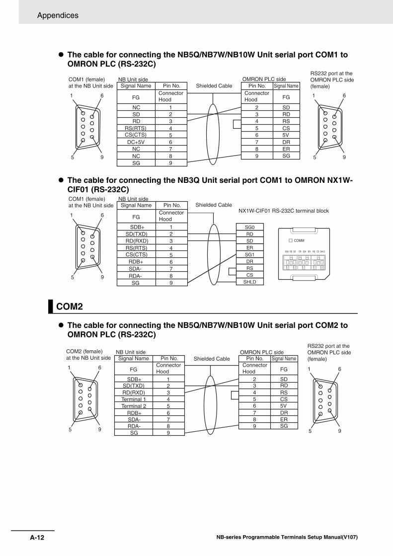
Appendices
A-12 NB-series Programmable Terminals Setup Manual(V107)
The cable for connecting the NB5Q/NB7W/NB10W Unit serial port COM1 to OMRON PLC (RS-232C)
The cable for connecting the NB3Q Unit serial port COM1 to OMRON NX1W-CIF01 (RS-232C)
The cable for connecting the NB5Q/NB7W/NB10W Unit serial port COM2 to OMRON PLC (RS-232C)
COM2
COM1 (female)at the NB Unit side
NB Unit sideShielded Cable
OMRON PLC sideSignal Name Pin No.
Connector Hood
Connector HoodFG
NC 123456789
SDRD
RS(RTS)CS(CTS)DC+5V
NCNCSG
1
5
6
9
1
5
6
9
RS232 port at theOMRON PLC side(female)Pin No.
23456789
Signal Name
FG
SDRDRSCS5VDRERSG
SG0RDSDER
SG1DRRSCS
SHLD
COMM
SG0 RD SD ER SG1 DR RS CS SHLD
NX1W-CIF01 RS-232C terminal block
COM1 (female)at the NB Unit side
1
5
6
9
NB Unit sideSignal Name Pin No.
Connector HoodFG
SDB+ 123456789
SD(TXD)RD(RXD)RS(RTS)CS(CTS)RDB+SDA-RDA-SG
Shielded Cable
COM2 (female)at the NB Unit side
NB Unit sideShielded Cable
OMRON PLC sideSignal Name Pin No.
Connector Hood
Connector HoodFG
SDB+ 123456789
SD(TXD)RD(RXD)Terminal 1Terminal 2
RDB+SDA-RDA-SG
1
5
6
9
1
5
6
9
RS232 port at theOMRON PLC side(female)Pin No.
23456789
Signal Name
FG
SDRDRSCS5VDRERSG
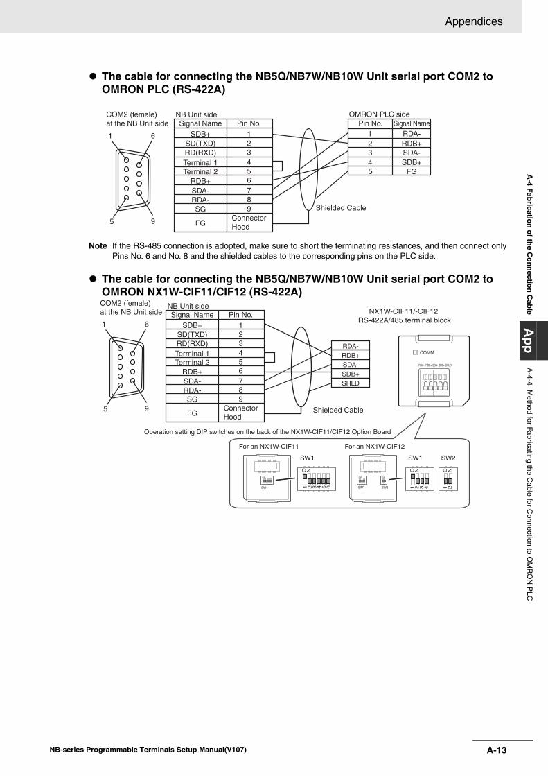
A-13
Appendices
NB-series Programmable Terminals Setup Manual(V107)
A-4 Fabrication of the C
onnection Cable
App
A-4-4 M
ethod for Fabricating the Cable for C
onnection to OM
RO
N P
LC
The cable for connecting the NB5Q/NB7W/NB10W Unit serial port COM2 to OMRON PLC (RS-422A)
Note If the RS-485 connection is adopted, make sure to short the terminating resistances, and then connect onlyPins No. 6 and No. 8 and the shielded cables to the corresponding pins on the PLC side.
The cable for connecting the NB5Q/NB7W/NB10W Unit serial port COM2 to OMRON NX1W-CIF11/CIF12 (RS-422A)
COM2 (female)at the NB Unit side
NB Unit side
Shielded Cable
Signal Name Pin No.SDB+
SD(TXD)RD(RXD)
23
1
456789
Terminal 1
RDA-
Terminal 2RDB+SDA-
SG
FGConnector Hood
1
5
6
9
OMRON PLC sidePin No.
1 RDA-RDB+SDA-SDB+
FG
2345
Signal Name
RDA-RDB+SDA-SDB+SHLD
COMM
RDA- RDB+ SDA- SDB+ SHLD
Operation setting DIP switches on the back of the NX1W-CIF11/CIF12 Option Board
O N1 2 3 4 5 6SW1
O N1 2 3 4 5 6
For an NX1W-CIF11 For an NX1W-CIF12
SW1 SW1 SW2
1 2 3 4
O N
1 2O N
SW1 SW2 1 2 3 4
O N
1 2O N
NX1W-CIF11/-CIF12 RS-422A/485 terminal block
COM2 (female)at the NB Unit side
1
5
6
9
NB Unit sideSignal Name Pin No.
SDB+SD(TXD)RD(RXD)
23
1
456789
Terminal 1
RDA-
Terminal 2RDB+SDA-
SG
FGConnector Hood
Shielded Cable
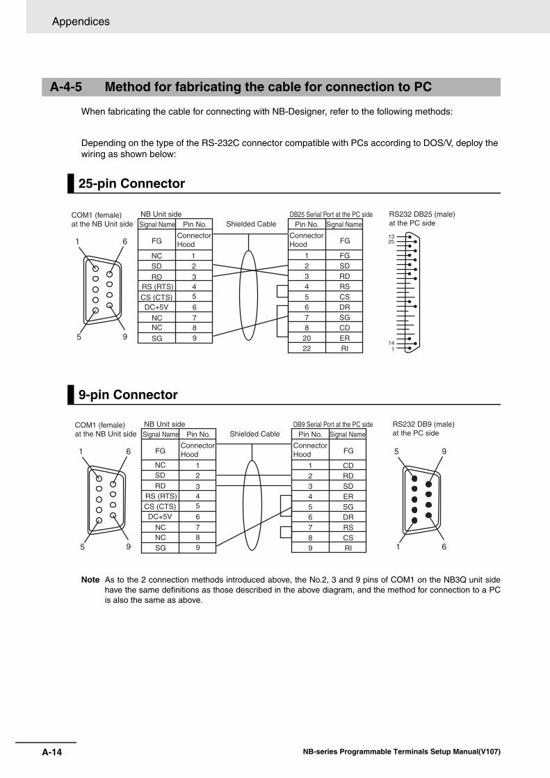
Appendices
A-14 NB-series Programmable Terminals Setup Manual(V107)
When fabricating the cable for connecting with NB-Designer, refer to the following methods:
Depending on the type of the RS-232C connector compatible with PCs according to DOS/V, deploy the wiring as shown below:
Note As to the 2 connection methods introduced above, the No.2, 3 and 9 pins of COM1 on the NB3Q unit sidehave the same definitions as those described in the above diagram, and the method for connection to a PCis also the same as above.
A-4-5 Method for fabricating the cable for connection to PC
25-pin Connector
9-pin Connector
1325
141
COM1 (female)at the NB Unit side
NB Unit sideShielded Cable
DB25 Serial Port at the PC side RS232 DB25 (male)at the PC sideSignal Name Signal NamePin No. Pin No.
FGConnector Hood
Connector Hood FG
NCSD
RDRS (RTS)CS (CTS)DC+5V
NCNC
SG
6789
45
3
21 1
2345678
2022
FGSDRDRSCSDRSGCDERRI
1
5
6
9
COM1 (female)at the NB Unit side
NB Unit sideShielded Cable
DB9 Serial Port at the PC side RS232 DB9 (male)at the PC sideSignal Name Signal NamePin No. Pin No.
FGConnector Hood
Connector Hood FG
NCSDRD
RS (RTS)CS (CTS)DC+5V
NCNCSG
6789
45
3
21 1
23456789
CDRDSDERSGDRRSCSRI
1
5
6
9
5
1
9
6
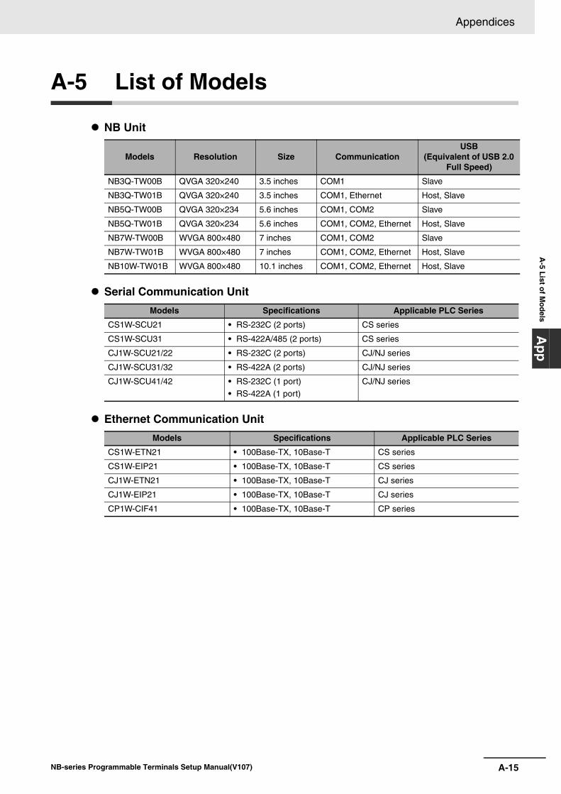
A-15
Appendices
NB-series Programmable Terminals Setup Manual(V107)
A-5 List of M
odelsA
pp
A-5 List of Models
NB Unit
Serial Communication Unit
Ethernet Communication Unit
Models Resolution Size CommunicationUSB
(Equivalent of USB 2.0 Full Speed)
NB3Q-TW00B QVGA 320×240 3.5 inches COM1 Slave
NB3Q-TW01B QVGA 320×240 3.5 inches COM1, Ethernet Host, Slave
NB5Q-TW00B QVGA 320×234 5.6 inches COM1, COM2 Slave
NB5Q-TW01B QVGA 320×234 5.6 inches COM1, COM2, Ethernet Host, Slave
NB7W-TW00B WVGA 800×480 7 inches COM1, COM2 Slave
NB7W-TW01B WVGA 800×480 7 inches COM1, COM2, Ethernet Host, Slave
NB10W-TW01B WVGA 800×480 10.1 inches COM1, COM2, Ethernet Host, Slave
Models Specifications Applicable PLC Series
CS1W-SCU21 • RS-232C (2 ports) CS series
CS1W-SCU31 • RS-422A/485 (2 ports) CS series
CJ1W-SCU21/22 • RS-232C (2 ports) CJ/NJ series
CJ1W-SCU31/32 • RS-422A (2 ports) CJ/NJ series
CJ1W-SCU41/42 • RS-232C (1 port)
• RS-422A (1 port)
CJ/NJ series
Models Specifications Applicable PLC Series
CS1W-ETN21 • 100Base-TX, 10Base-T CS series
CS1W-EIP21 • 100Base-TX, 10Base-T CS series
CJ1W-ETN21 • 100Base-TX, 10Base-T CJ series
CJ1W-EIP21 • 100Base-TX, 10Base-T CJ series
CP1W-CIF41 • 100Base-TX, 10Base-T CP series
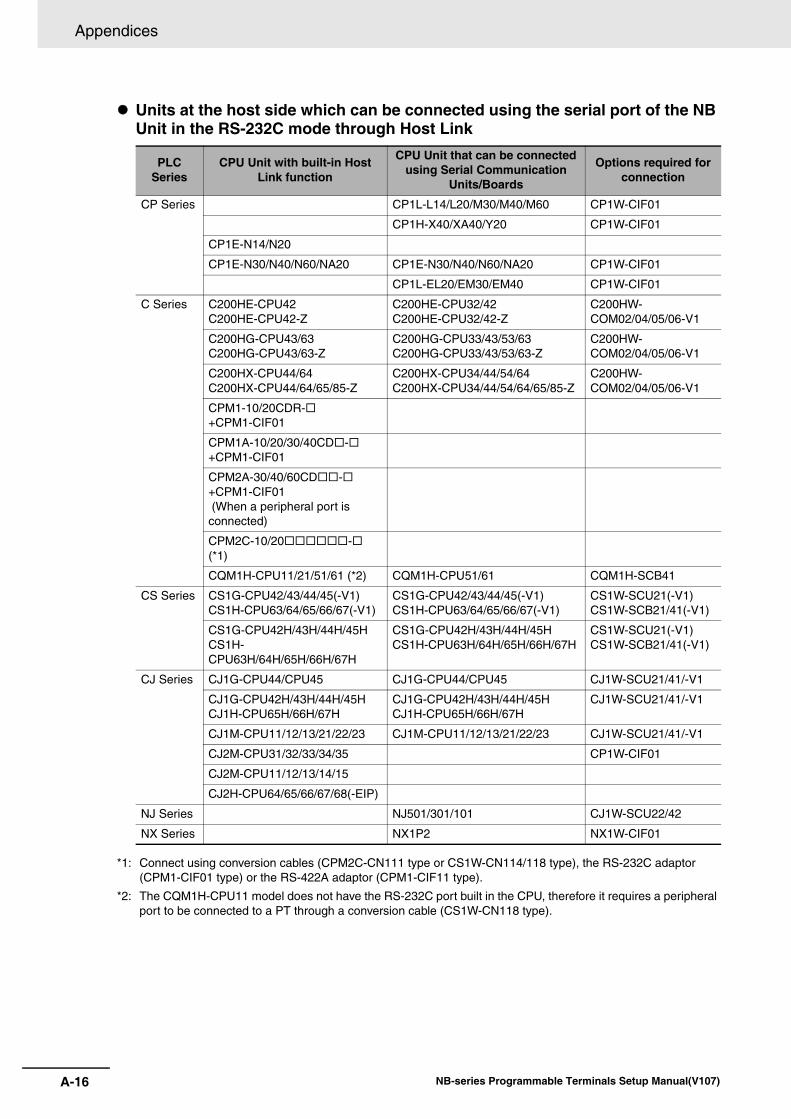
Appendices
A-16 NB-series Programmable Terminals Setup Manual(V107)
Units at the host side which can be connected using the serial port of the NB Unit in the RS-232C mode through Host Link
*1: Connect using conversion cables (CPM2C-CN111 type or CS1W-CN114/118 type), the RS-232C adaptor (CPM1-CIF01 type) or the RS-422A adaptor (CPM1-CIF11 type).
*2: The CQM1H-CPU11 model does not have the RS-232C port built in the CPU, therefore it requires a peripheral port to be connected to a PT through a conversion cable (CS1W-CN118 type).
PLC Series
CPU Unit with built-in Host Link function
CPU Unit that can be connected using Serial Communication
Units/Boards
Options required for connection
CP Series CP1L-L14/L20/M30/M40/M60 CP1W-CIF01
CP1H-X40/XA40/Y20 CP1W-CIF01
CP1E-N14/N20
CP1E-N30/N40/N60/NA20 CP1E-N30/N40/N60/NA20 CP1W-CIF01
CP1L-EL20/EM30/EM40 CP1W-CIF01
C Series C200HE-CPU42 C200HE-CPU42-Z
C200HE-CPU32/42 C200HE-CPU32/42-Z
C200HW-COM02/04/05/06-V1
C200HG-CPU43/63 C200HG-CPU43/63-Z
C200HG-CPU33/43/53/63C200HG-CPU33/43/53/63-Z
C200HW-COM02/04/05/06-V1
C200HX-CPU44/64 C200HX-CPU44/64/65/85-Z
C200HX-CPU34/44/54/64 C200HX-CPU34/44/54/64/65/85-Z
C200HW-COM02/04/05/06-V1
CPM1-10/20CDR- +CPM1-CIF01
CPM1A-10/20/30/40CD- +CPM1-CIF01
CPM2A-30/40/60CD- +CPM1-CIF01 (When a peripheral port is connected)
CPM2C-10/20-(*1)
CQM1H-CPU11/21/51/61 (*2) CQM1H-CPU51/61 CQM1H-SCB41
CS Series CS1G-CPU42/43/44/45(-V1)CS1H-CPU63/64/65/66/67(-V1)
CS1G-CPU42/43/44/45(-V1) CS1H-CPU63/64/65/66/67(-V1)
CS1W-SCU21(-V1) CS1W-SCB21/41(-V1)
CS1G-CPU42H/43H/44H/45H CS1H-CPU63H/64H/65H/66H/67H
CS1G-CPU42H/43H/44H/45H CS1H-CPU63H/64H/65H/66H/67H
CS1W-SCU21(-V1) CS1W-SCB21/41(-V1)
CJ Series CJ1G-CPU44/CPU45 CJ1G-CPU44/CPU45 CJ1W-SCU21/41/-V1
CJ1G-CPU42H/43H/44H/45H CJ1H-CPU65H/66H/67H
CJ1G-CPU42H/43H/44H/45H CJ1H-CPU65H/66H/67H
CJ1W-SCU21/41/-V1
CJ1M-CPU11/12/13/21/22/23 CJ1M-CPU11/12/13/21/22/23 CJ1W-SCU21/41/-V1
CJ2M-CPU31/32/33/34/35 CP1W-CIF01
CJ2M-CPU11/12/13/14/15
CJ2H-CPU64/65/66/67/68(-EIP)
NJ Series NJ501/301/101 CJ1W-SCU22/42
NX Series NX1P2 NX1W-CIF01
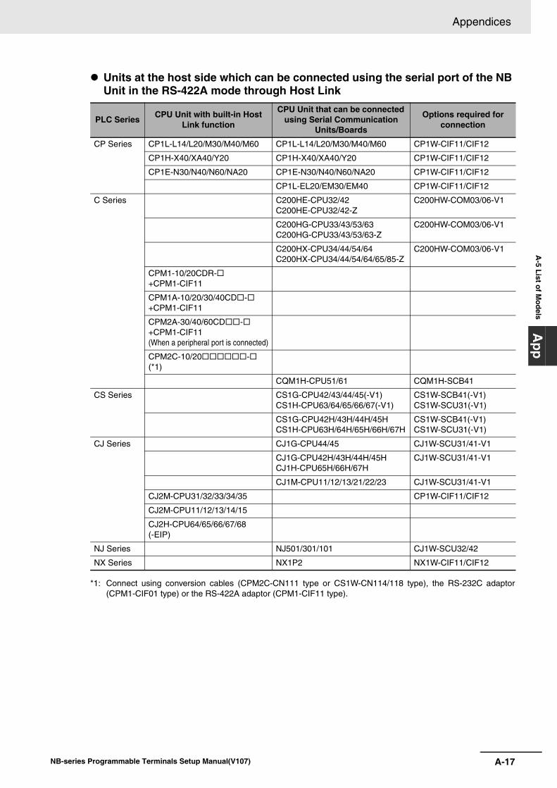
A-17
Appendices
NB-series Programmable Terminals Setup Manual(V107)
A-5 List of M
odelsA
pp
Units at the host side which can be connected using the serial port of the NB Unit in the RS-422A mode through Host Link
*1: Connect using conversion cables (CPM2C-CN111 type or CS1W-CN114/118 type), the RS-232C adaptor(CPM1-CIF01 type) or the RS-422A adaptor (CPM1-CIF11 type).
PLC Series CPU Unit with built-in Host Link function
CPU Unit that can be connected using Serial Communication
Units/Boards
Options required for connection
CP Series CP1L-L14/L20/M30/M40/M60 CP1L-L14/L20/M30/M40/M60 CP1W-CIF11/CIF12
CP1H-X40/XA40/Y20 CP1H-X40/XA40/Y20 CP1W-CIF11/CIF12
CP1E-N30/N40/N60/NA20 CP1E-N30/N40/N60/NA20 CP1W-CIF11/CIF12
CP1L-EL20/EM30/EM40 CP1W-CIF11/CIF12
C Series C200HE-CPU32/42 C200HE-CPU32/42-Z
C200HW-COM03/06-V1
C200HG-CPU33/43/53/63 C200HG-CPU33/43/53/63-Z
C200HW-COM03/06-V1
C200HX-CPU34/44/54/64 C200HX-CPU34/44/54/64/65/85-Z
C200HW-COM03/06-V1
CPM1-10/20CDR-+CPM1-CIF11
CPM1A-10/20/30/40CD- +CPM1-CIF11
CPM2A-30/40/60CD- +CPM1-CIF11 (When a peripheral port is connected)
CPM2C-10/20- (*1)
CQM1H-CPU51/61 CQM1H-SCB41
CS Series CS1G-CPU42/43/44/45(-V1) CS1H-CPU63/64/65/66/67(-V1)
CS1W-SCB41(-V1) CS1W-SCU31(-V1)
CS1G-CPU42H/43H/44H/45H CS1H-CPU63H/64H/65H/66H/67H
CS1W-SCB41(-V1) CS1W-SCU31(-V1)
CJ Series CJ1G-CPU44/45 CJ1W-SCU31/41-V1
CJ1G-CPU42H/43H/44H/45H CJ1H-CPU65H/66H/67H
CJ1W-SCU31/41-V1
CJ1M-CPU11/12/13/21/22/23 CJ1W-SCU31/41-V1
CJ2M-CPU31/32/33/34/35 CP1W-CIF11/CIF12
CJ2M-CPU11/12/13/14/15
CJ2H-CPU64/65/66/67/68 (-EIP)
NJ Series NJ501/301/101 CJ1W-SCU32/42
NX Series NX1P2 NX1W-CIF11/CIF12
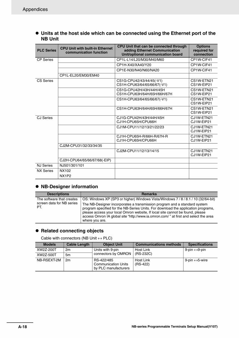
Appendices
A-18 NB-series Programmable Terminals Setup Manual(V107)
Units at the host side which can be connected using the Ethernet port of the NB Unit
NB-Designer information
Related connecting objectsCable with connectors (NB Unit ↔ PLC)
PLC Series CPU Unit with built-in Ethernet communication function
CPU Unit that can be connected through adding Ethernet Communication
Unit/optional communication board
Options required for connection
CP Series CP1L-L14/L20/M30/M40/M60 CP1W-CIF41
CP1H-X40/XA40/Y20 CP1W-CIF41
CP1E-N30/N40/N60/NA20 CP1W-CIF41
CP1L-EL20/EM30/EM40
CS Series CS1G-CPU42/43/44/45(-V1)CS1H-CPU63/64/65/66/67(-V1)
CS1W-ETN21CS1W-EIP21
CS1G-CPU42H/43H/44H/45HCS1H-CPU63H/64H/65H/66H/67H
CS1W-ETN21CS1W-EIP21
CS1H-CPU63/64/65/66/67(-V1) CS1W-ETN21CS1W-EIP21
CS1H-CPU63H/64H/65H/66H/67H CS1W-ETN21CS1W-EIP21
CJ Series CJ1G-CPU42H/43H/44H/45HCJ1H-CPU65H/CPU66H
CJ1W-ETN21CJ1W-EIP21
CJ1M-CPU11/12/13/21/22/23 CJ1W-ETN21CJ1W-EIP21
CJ1H-CPU65H-R/66H-R/67H-RCJ1H-CPU65H/CPU66H
CJ1W-ETN21CJ1W-EIP21
CJ2M-CPU31/32/33/34/35
CJ2M-CPU11/12/13/14/15 CJ1W-ETN21CJ1W-EIP21
CJ2H-CPU64/65/66/67/68(-EIP)
NJ Series NJ501/301/101
NX Series NX102NX1P2
Descriptions RemarksThe software that creates screen data for NB series PT.
OS: Windows XP (SP3 or higher) Windows Vista/Windows 7 / 8 / 8.1 / 10 (32/64-bit) The NB-Designer incorporates a transmission program and a standard system program specified for the NB-Series Units. For download the application programs, please access your local Omron website, If local site cannot be found, please access Omron IA global site “http://www.ia.omron.com/ ” at first and select the area where you are.
Models Cable Length Object Unit Communications methods SpecificationsXW2Z-200T 2m Units with 9-pin
connectors by OMRONHost Link(RS-232C)
9-pin ↔9-pinXW2Z-500T 5m
NB-RSEXT-2M 2m RS-422/485 Communication Units by PLC manufacturers
Host Link(RS-422)
9-pin ↔5-wire
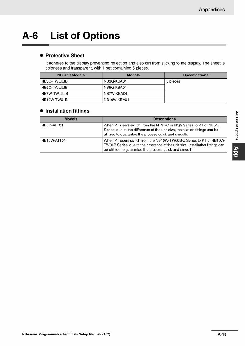
A-19
Appendices
NB-series Programmable Terminals Setup Manual(V107)
A-6 List of O
ptionsA
pp
A-6 List of Options
Protective SheetIt adheres to the display preventing reflection and also dirt from sticking to the display. The sheet is colorless and transparent, with 1 set containing 5 pieces.
Installation fittings
NB Unit Models Models Specifications
NB3Q-TWB NB3Q-KBA04 5 pieces
NB5Q-TWB NB5Q-KBA04
NB7W-TWB NB7W-KBA04
NB10W-TW01B NB10W-KBA04
Models Descriptions
NB5Q-ATT01 When PT users switch from the NT31/C or NQ5 Series to PT of NB5Q Series, due to the difference of the unit size, installation fittings can be utilized to guarantee the process quick and smooth.
NB10W-ATT01 When PT users switch from the NB10W-TW00B-Z Series to PT of NB10W-TW01B Series, due to the difference of the unit size, installation fittings can be utilized to guarantee the process quick and smooth.
Appendices
A-20 NB-series Programmable Terminals Setup Manual(V107)
RS-422A/RS-485 Communication Cable
USB MemoryIt can be connected to the USB HOST port on the back of PT to perform the uploading, downloading, project operation and storage of related data.
Models Descriptions
NB-RSEXT-2M Only applies to the COM2 port of the NB series product, when performing communications using RS-422A/RS485, can be equipped with this communication cable.
Cause a short circuit at terminal resistance.How to use: When NB5Q/NB7W/NB10W-TWB is used, open the connector of RS-422A/485 communication cable and cause a short circuit at PIN4 and PIN5. Make sure not to cause short circuit the other pins except PIN4 and PIN5. When the short circuit is completed, assemble the connector. When NB3Q-TWB Unit is used, set DIP switch SW3 to ON.
Recommended Purchasing Model Descriptions
FZ-MEM2G USB disk with 2GB capacity manufactured by OMRON
FZ-MEM8G USB disk with 8GB capacity manufactured by OMRON
NB Model
Pin NO.123NB
Serial PortD-Sub 9Pin
(Female)
456789
SignalSDB+
SDRD
TerminalTerminal
RDB+SDA-RDA-SG
Hood FG
SignalSDB+
SDRDRSCS
RDB+SDA-RDA-SGFG
NB5Q /NB7W/NB10W-TW��B
NB3Q-TW��B
signal wire
shield wire
Conform to UL2464, AWG28
Red
White
Black
Brown
Blue
Revision-1NB-series Programmable Terminals Setup Manual(V107)
Revision History
A manual revision code appears as a suffix to the Catalog number on the front cover of the manual.
Revision code Date Revised content
01 October 2011 Original production
02 February 2012 • Adding optional RS-422A / RS485 communication cable in Appendix-6.
• Correcting the descriptions of the battery.
03 April 2012 Adding descriptions and new functions of NB5Q/NB7W-TW01B model.
04 August 2012 Adding descriptions and new functions of NB3Q-TW00B/TW01B and NB10W-TW01B models.
05 October 2012 • Correcting the settings for CS1W-ETN21.
• Deleting content related to C200-LK201/LK202.
06 December 2012 • Correction related to the backlight lamp and rubber packing maintenance in Precautions for Safe Use.
• Adding descriptions of the Pictbridge printing function.
07 December 2012 • Adding descriptions of the power supply and wire connection in Precautions for Safe Use.
• Adding notes of the specifications in Appendix.
08 April 2013 Changes and corrections
09 July 2016 Changes and corrections
10 October 2016 Changes and corrections
11 November 2016 Changes related to OS.
12 March 2017 Changes and corrections
13 December 2017 Changes and corrections
14 April 2018 Changes and corrections
15 October 2018 Changes and corrections
Cat. No. V107-E1-
Revision code

Revision-2 NB-series Programmable Terminals Setup Manual(V107)


Authorized Distributor:
In the interest of product improvement, specifications are subject to change without notice.
Cat. No. V107-E1-15 1018
© OMRON Corporation 2011-2018 All Rights Reserved.
OMRON Corporation Industrial Automation Company
OMRON ELECTRONICS LLC2895 Greenspoint Parkway, Suite 200 Hoffman Estates, IL 60169 U.S.A.Tel: (1) 847-843-7900/Fax: (1) 847-843-7787
Regional HeadquartersOMRON EUROPE B.V.Wegalaan 67-69, 2132 JD HoofddorpThe NetherlandsTel: (31)2356-81-300/Fax: (31)2356-81-388
Contact: www.ia.omron.comKyoto, JAPAN
OMRON ASIA PACIFIC PTE. LTD.No. 438A Alexandra Road # 05-05/08 (Lobby 2), Alexandra Technopark, Singapore 119967Tel: (65) 6835-3011/Fax: (65) 6835-2711
OMRON (CHINA) CO., LTD.Room 2211, Bank of China Tower, 200 Yin Cheng Zhong Road, PuDong New Area, Shanghai, 200120, ChinaTel: (86) 21-5037-2222/Fax: (86) 21-5037-2200