Embed Size (px)
Citation preview

Document No: NBII063 Author: DR Revision #: See Revision Block Below Created: DR Revised By: See Revision Block Below Reviewed By: RB/MS Date Revised: See Revision Block Below Approved By: RB
VECTRIX SCOOTER DIAGNOSTIC GUIDE (TEOP) Revision
Level Date Release Description Revised By 01 10/13/2011 Initial Draft DR 02 11/3/2011 Revised for Scooter Update DR 03 1/11/2012 Additions for new rev DR 04 1/17/2012 Released per ECN VTRX-10679 DR
NBII063 Vectrix Scooter Diag Guide.doc Page 1 of 36 printed: 01/23/12
1.0 Application
Vectrix Family of electric scooter products including VX-1, VX-2, and VX-3.
2.0 Scope The Vectrix Scooter diagnostic program allows a PC to communicate with one of the Vectrix electric scooters. The software allows the user to view the internal operations of the scooter. The software offers many features including but not limited to the following:
• Monitor CAN bus message traffic to provide an enhanced diagnostic display. • Upload current Riding History events. • View the Battery Status during normal operation and charge cycles. • Calibration of the Encoder. • Provide the capability to update firmware associated with individual subsystems. (charger, ICM ,
motor controller, BMS etc) • Allow user the ability to control and monitor the scooter remotely from the PC . • Throttle calibration
3.0 Definitions PGN Parameter Group Number CAN Controller Area Network ICM Interface Control Module BMS Battery Monitoring System MC Motor Controller

NBII063 Vectrix Scooter Diag Guide.doc page 2 of 36 printed: 01/23/12
4.0 Associated Material
None.
5.0 Equipment
1) Windows XP or Windows 7 based Computer
2) Grid Connect USB to CAN converter
3) Vectrix Scooter
6.0 Equipment Setup
6.1 Compatibity We are constantly updating our systems to allow the scooter diagnostics to interface to more of our scooter subsystems. Refer to the appropriate Product Manual to determine if your vehicle is compatible.
6.2 Warning
Some features of this program can and will rotate the rear wheel which will require that the rear wheel be elevated prior to initializing this segment of the diagnostics. In the case of the VX1, and VX3 Instrument Cluster and encoder pages the throttle control is transferred to the PC. Please insure that the rear wheel is elevated and is free standing. Keep hands and feet and loose clothing away from the rear wheel when it is rotating.
NBII063 Vectrix Scooter Diag Guide.doc page 3 of 36 printed: 01/23/12
7.0 Installation The Vectrix Scooter Diagnostic program can be installed from a single executable file located on the dealer portal . It is important to remember to remove any previous version of the program which has been installed on the target PC. Previous programs must be manually removed using the windows add/remove software utility. To install the diagnostics program, use windows explorer, and locate the file VectrixDiagnosticGUI_XXSetup.exe( where XX is 32 for windows XP and 64 for windows 7 Operating systems), and double click on it to begin the installation process. Figure 1 shows the beginning of the installation process.
Figure 1 Begin Installation Left Click the Next button to proceed.

NBII063 Vectrix Scooter Diag Guide.doc page 4 of 36 printed: 01/23/12
The next screen (figure 2) is provided to allow the user to install the program at the user designated location. The default location is c:\program files\VectrixCorporation\VectrixDiagnosticGUI_xx\
Figure 2 Install Browse location Provide the installation location by using the Browse button. Once the desired location has been entered click the next button to proceed. At this point the user is prompted with the final exit point prior to the installation.

NBII063 Vectrix Scooter Diag Guide.doc page 5 of 36 printed: 01/23/12
Figure 3 Install location Left click the Next key to begin installation. The installation process takes a short amount of time, and the user will be prompted with the following screen at the end of the installation process.

NBII063 Vectrix Scooter Diag Guide.doc page 6 of 36 printed: 01/23/12
Figure 4 Install complete Left Click the finish key button to complete the installation process. The Vectrix Scooter icon should now be
visible on the computer screen. VectrixIcon.ico
7.1 Common Diagnostic Page Start the Diagnostic program by double clicking on the Vectrix diagnostic Icon on the computer screen.
VectrixIcon.ico The program starts up with a common frame around the tabbed options which are specific to the connected scooter. The common frame has bike selection group box, Error status and CAN status text across the top of the page. The example Figure 5 is the startup associated with a VX1 Lithium scooter. The first item to set upon start up is the type of bike that the program is interfaced to. This selection group box is circled in red.

NBII063 Vectrix Scooter Diag Guide.doc page 7 of 36 printed: 01/23/12
Figure 5. Start up screen for VX1Li
Figure 6 Common Status screen Status display across the top frame is an error display. If no errors are detected “NO Faults” is written and the text is highlighted in green (see figure 6). If an error is detected it, will be displayed in this window highlighted in red. To the right of the status display is the CAN bus status. In order for the program to capture data the scooter needs to be turned on (CAN bus active). If the scooter is not on, the program viewing and selection is very limited. Note: The tabbed pages are scooter specific and will be covered in the specific section for each.
7.2 VX1Li The VX1Li has the most embedded control and is the most complex of the four bikes supported by the scooter diagnostics program.
7.2.1 Service The service tab Figure 7 is the first page viewable, and has information about the current state of the scooter when the program starts. The majority of the information on this page is related to the battery performance. Each Cell voltage is displayed along with the temperature sensors monitoring the batteries. The Motor controller and charger state summary is also presented.

NBII063 Vectrix Scooter Diag Guide.doc page 8 of 36 printed: 01/23/12
Figure 7 Service Page
7.2.2 BMS Temperatures The upper left hand corner displays the current battery temperatures reported by the battery monitoring subsystems (BMS) figure 8.
Figure 8 BMS Temperature summary The Diagnostic program reads all the battery voltages along with each of the four ambient temperatures, sorts and displays ambient, low and high temperatures for each BMS Board. Any temperature detected over 50C will be highlighted in red as a problem.

NBII063 Vectrix Scooter Diag Guide.doc page 9 of 36 printed: 01/23/12
7.2.3 Charging modes The charger modes display of the screen is valid only when charging (figure 9). Depending on the battery status the VX1 charger will operate in different modes. The charger mode during a charge cycle is extracted from the CAN message. The current mode will be shown as checked.
Figure 9 Charger summary
7.2.4 Motor Control Status The pane in the middle of the screen (figure 10) is displaying information from the motor controller. This display has the sum of all the individual BMS voltages, the motor controller sensed bus voltage, and current, and in the case of charging mode the charge voltage, and current delivered.
Figure 10 Motor control summary 7.2.5 Battery Monitoring cell Voltages. The largest display is the BMS reported individual battery pack cell voltages. Each Cell in the battery pack (40 total) is monitored during both riding and charging modes and is available on the CAN bus. The Battery health can be monitored using this pane. Viewing limit settings can be adjusted by the two text boxes (Min and Max) at the bottom of the BMS display Figure 11. Any cell voltage detected below the min value will be highlighted in yellow, while a cell voltage detected above the Max setting will be highlighted in Red.

NBII063 Vectrix Scooter Diag Guide.doc page 10 of 36 printed: 01/23/12
Figure 11 BMS Battery Cell voltage 7.2.6 Battery Cell Monitoring Recording One feature of battery monitoring is to provide a recording of cell voltages over time. The Recording capability allows the user the ability to record each of the cell voltages over a programmable interval. This interval (figure 12) can be adjusted by entering the recording interval in the text box shown. A file name dialog is available for setting up the file in which to log the voltages. The format of the recorded file is comma delimited text.
Figure 12 BMS Voltage recording

NBII063 Vectrix Scooter Diag Guide.doc page 11 of 36 printed: 01/23/12
7.3 Data Summary The Data Summary page (figure 13) was added to provide a view of all the CAN modules in the scooter. Each board background is highlighted by a red color when the test is initiated. The Background color turns green when the diagnostic program has detected a correct message sequence from each module. An additional subset of information that the module provides is displayed to validate performance.
Figure 13 Data Summary Page 7.3.1 Instrument Cluster The Instrument cluster outputs a time stamp. This value is captured and is shown in Figure 14.
Figure 14 Instrument cluster display.

NBII063 Vectrix Scooter Diag Guide.doc page 12 of 36 printed: 01/23/12
7.3.2 Charger The charger display (figure 15) contains the dc bus voltage detected by the charger. The current display is current supplied by the charger during a charge cycle. In a non charge cycle it will display 0.0. The charger mode is the charger mode during a charge cycle. Valid charger modes in a normal charging sequence are 1) Constant Current 2) Constant Voltage 3) Equalization 4) Complete
Figure 15 Charger display during non charge cycle. 7.3.3 Interface Control Module (ICM) The ICM is used for most user input on the scooter. Figure 16 shows Throttle, Brake, lighting, and Indicators are routed through this module, and broadcast on the CAN bus. The bar graph shows the raw throttle status. The green band indicates an acceptable level for the throttle in the neutral position. The blue is the range for the throttle full on, with the Yellow the nominal range for full regen. The throttle test should be performed with the side stand down to insure the scooter is not enabled. Brake, Kill switch and side stand check boxes will display the current status of each.
Figure 16. Interface Control Module

NBII063 Vectrix Scooter Diag Guide.doc page 13 of 36 printed: 01/23/12
7.3.4 Battery Monitoring. Figure 17 is a typical display for each of the BMS boards. The display contains a data summary of the high and low cell voltage and temperatures the board has measured during the last CAN update. Each BMS board monitors 10 cell voltages within its battery module.
Figure 17 BMS board #1 Data summary.

NBII063 Vectrix Scooter Diag Guide.doc page 14 of 36 printed: 01/23/12
7.3.5 Motor Controller The Motor Controller display (Figure 18) displays readings from the motor controller temperature sensor’s, bus current, and voltage along with any detected faults. The four boxes at the top of the motor controller dispay identify the back light regeneration mode, the motor controller go signal, motor controller ready, and Vehicle Power enable.
Figure 18. Motor Controller display. 7.4 Encoder Tab The encoder tab (Figure 19) has two functions. The first is to provide a calibration control for the Encoder. When the user clicks this button a command is sent to the motor controller to perform a calibration of the encoder. The rear wheel will spin and the slider bar will move to the correct calibration value. Subsequent calibrations performed should result in the same value +/- 2 counts. As noted on the display the rear wheel needs to be elevated during the calibration since it will spin. Also the side stand must be in the up position, and the cut off switch off. The Check Phases button provides for the verification that the three phase wiring to the motor is correct. The test is started by clicking the check phases button. The test is successful if the rear wheel spins slowly in the forward direction for a short period of time. If the wheel rotates in the reverse direction the phase rotation of the motor leads is incorrect.

NBII063 Vectrix Scooter Diag Guide.doc page 15 of 36 printed: 01/23/12
Figure 19 Encoder Page 7.5 Command Tab The command page allows the user to have the flexibility to create specific messages to be sent to the different controllers in the motorcycle. This feature requires the user to have knowledge of the internal CAN command structure. The commands can be imported from dedicated command xml file for this display. This feature will provide a benefit for remote testing, and troubleshooting for the VX1. Vectrix field service will send out this xml file and have the user import it thus creating a custom test page with commands generated to support the specific test. The page below is an example of a command that was generated to set the VX1 time.

NBII063 Vectrix Scooter Diag Guide.doc page 16 of 36 printed: 01/23/12
Figure 20 Command Page
The edit button brings up a dialog that will provide the user the ability to define the custom command.
Figure 21 Command Edit page The CAN PGN, data message and label can be defined here. Hitting the accept button will store the custom command in a database for storage and retrieval at a later session. Clicking the send button will trigger this message to be sent once per mouse click.

NBII063 Vectrix Scooter Diag Guide.doc page 17 of 36 printed: 01/23/12
Commands generated can be saved to an XML file for future use by clicking the save button and following the standard windows file dialog procedure. The commands can be restored for use at a later date by hitting the import command button and selecting any previously saved command file. 7.6 Firmware download tab The firmware download tab provides the capability to update firmware revisions in the VX1 microcontrollers.
Figure 22 Firmware download page As shown in Figure 22 Battery Charger, Motor Controller, ICM and BMS microcontroller firmware can be updated. Each device has its own unique browse control to locate the firmware update file, and a program button to initiate the firmware download process. NOTE: The Firmware file for each device has its own unique name. If you are unsure as to the correct file please call Vectrix field service for support. Programming the wrong file will render the module inoperable. The Firmware Ver. contains the current firmware version read from the scooter. This is used to verify the correct version is running on the device. In the instance of the BMS in Figure 22 the NA indicates that the firmware version has not been reported and is in need of an update. The version information will be the first thing to check on each VX1 being serviced. During the download a progress bar is updated with the percentage complete for the firmware update, along with a short message indicating the current state of the download. Detailed messages during the download process can be found on the status tab discussed in section 6.10.

NBII063 Vectrix Scooter Diag Guide.doc page 18 of 36 printed: 01/23/12
7.7 CAN Bus Test This CAN bus test is used to verify the integrity of the bus. The test consists of sending the charger a standard message to set the fuel gauge to a specific value. This value is then compared against a subsequent standard charger fuel gauge broadcast message. Any difference is considered an error and the error counter is incremented. A new fuel gauge value is incremented and sent to the charger for another test. This test will run continuously until commanded to stop with an error count box along with the current fuel gauge setting. To terminate this test the operator needs to hit the stop fuel gauge test before proceeding to any other diagnostic tabs.
Figure 23 CAN Bus Test The example above shows a test being run with 97 test iterations and 39 CAN bus errors detected.

NBII063 Vectrix Scooter Diag Guide.doc page 19 of 36 printed: 01/23/12
7.8 Parameter Plotting Tab The Plotting page is used to capture and plot internal parameters of the VX1. The parameters are listed on the left side of the screen. Checking the box (which Figure 11 shows) next to the parameter will enable it to be one of the parameters selected for plotting.
Figure 24 Plotting The Plot configuration parameters consist of the filename and directory path browse dialog, along with sample period, total samples or test time limit settings as shown below. Checking the Live Display box will enable the plotting function to be shown on the screen once the plotting is enabled (see Figure 24). Otherwise the data will be logged to disk until the test is concluded and then displayed.

NBII063 Vectrix Scooter Diag Guide.doc page 20 of 36 printed: 01/23/12
Figure 25 Plot Configuration The Start Sampling button enables the test. The button changes to Stop Sampling during the test and is used to stop the plotting function. Below is a graph of the MC bus voltage at the completion of the plotting function test
Figure 26 Plotting Example Motor controller Bus Voltage

NBII063 Vectrix Scooter Diag Guide.doc page 21 of 36 printed: 01/23/12
Note the PrintPreview will allow the graph to be printed to a local printer if connected, or saved to a file which can be imported to an excel spreadsheet. Once this file has been saved it can be retrieved at any time and plotted out in the format above. This can be done by using the plot data file box shown in figure 27 below.
Figure 27. The file can be loaded using the browse key, and when selected the file will be imported and plotted in the format used for the live display shown above. 7.9 Riding history The riding history tab is used to upload events which have been recorded by the motor controller. The blank page is shown below.
Figure 28 Riding History page To retrieve the riding history hit the Upload Riding History button in the upper left hand corner. This action will cause the motor controller to send the logged riding history for display. The progress bar will update with the upload completion status.

NBII063 Vectrix Scooter Diag Guide.doc page 22 of 36 printed: 01/23/12
Figure 29 shows the riding history data content of discrete events which identify • Distance • AmpHours expended during the ride. • Fault code see appendix A for detailed listing of fault code. • Fuel Start • Fuel end • Charge Amp hours. • Highest Battery Temperature • Lowest Cell Voltage • Ride Time
Figure 29 Riding history upload The Save Riding history button (see figure 28) is used to save the recently uploaded motor controller riding history. The data will be saved in a text based comma delimited file which can be viewed using Excel or similar text viewing programs.

NBII063 Vectrix Scooter Diag Guide.doc page 23 of 36 printed: 01/23/12
7.10 View PGN This page allows for the creation and usage of custom CAN messages. This page requires that the user either have access to the scooter CAN message protocol, Or a XML file with these custom commands can be furnished by Vectrix for viewing any valid CAN message in the scooter. The created custom commands can be saved to a user designated file for use in a later test. The saved file can be imported for future tests.
Figure 30 View PGN Once these are created the text box is filled in with the live reading of the PGN.

NBII063 Vectrix Scooter Diag Guide.doc page 24 of 36 printed: 01/23/12
7.11 Dash This page is intended to mimic the scooter dash page. The page provides Icons which show the status of the user controls, and indicators.
Figure 31 Dash Page

NBII063 Vectrix Scooter Diag Guide.doc page 25 of 36 printed: 01/23/12
7.11.1 Dash Icons
Dashboard Icons
• Left turn• Right turn• Low Beam• High Beam• Charging
Fig 32 Dash Icons
Dashboard Icons con’t• Maintenance Required • Temperature warning• Kickstand down
• Go indicator. THROTTLE WILLSPIN REAR WHEEL.
• Throttle is in Reverse• Parking lamps enabled
Fig 33 Dash Icons.

NBII063 Vectrix Scooter Diag Guide.doc page 26 of 36 printed: 01/23/12
7.11.2 Fuel Gauge The fuel gauge is a parameter which is stored in the scooter. It is updated to reflect any discharge during operation and charge state after a charge cycle. In the event that the parameter is no longer valid either by a change in charger or battery pack, the fuel gauge needs to be updated with the correct value. The Dash function allows the user to set the current fuel gauge stored in the scooter.
Fig 34.Live reading of fuel gauge. Reading 26%
Figure 35 fuel gauge control To change the fuel gauge enter the charge state percentage in the text box provided and hit the set fuel gauge button. This new value will be displayed on the bar graph shown above. 7.11.3 Odometer The odometer section of the dash page displays both odometer, and trip mileage in either
Fig 36 Odometer display.

NBII063 Vectrix Scooter Diag Guide.doc page 27 of 36 printed: 01/23/12
7.11.4 Dash Monitor / Control The bottom part of the Dash page has the monitor/control functions for the scooter. The Monitor functions will display the status of the actual scooter controls. Brake, side stand, kill switch will be updated as these controls are exercised on the scooter. Selecting the monitor radio button will enable Monitor mode. The control mode allows the operator to control the scooter from the dash page. NOTE: in control mode it is possible to move the rear wheel by altering the throttle control. Please elevate the rear wheel.
Figure 37 Monitor / Control

NBII063 Vectrix Scooter Diag Guide.doc page 28 of 36 printed: 01/23/12
7.11.5 Date time setting The dash page also allows the user to set the date / time in the scooter. Two options are available for setting the time. The first is to use the computer time as the desired time. Click the computer time button and then hit the set date/time button. If a time different from the computer time is desired the user can set the time in the text boxes and hit set date/time button.
Fig 38 Set Date/time controls.

NBII063 Vectrix Scooter Diag Guide.doc page 29 of 36 printed: 01/23/12
8.0 VX1 Ni The Vx1 Ni scooter architecture is very similar to the VX1Li. Any functionality that is shared between scooters will be covered in section 6 and will be referenced here. Once connected to the Aux CAN port make sure the button next to the VX1Ni button in the Select Bike group box is selected below. 8.1 Data Summary The Data summary page is identical to the VX1Li data summary with the exception that a temperature sensor package replaces the Battery Monitoring system.
Fig 39 VX1Ni Data summary page . As with the Li scooter the message updates from each subsystem control the background color. Any subsystem not reporting critical CAN messages will be highlighted in red. 8.1.1 Instrument Cluster---- See Section 7.3.1 for details. 8.1.2 Charger------------------ See Section 7.3.2 for details. 8.1.3 ICM-----------------------See Section 7.3.3 for details.

NBII063 Vectrix Scooter Diag Guide.doc page 30 of 36 printed: 01/23/12
8.1.4 Temperature Sensor
Figure 40 VX1Ni Temperature sensors display. The Temperature sensor boards monitor critical temperatures during riding and charging states. They report the temperatures to the charger. The charger provides control over the fans in the battery compartment based on these temperature readings. 8.1.5 Motor Controller------See Section 7.3.5 for details. 8.2 Commands The Commands page is identical to the VX1Li commands page documented in section 6.2
NBII063 Vectrix Scooter Diag Guide.doc page 31 of 36 printed: 01/23/12
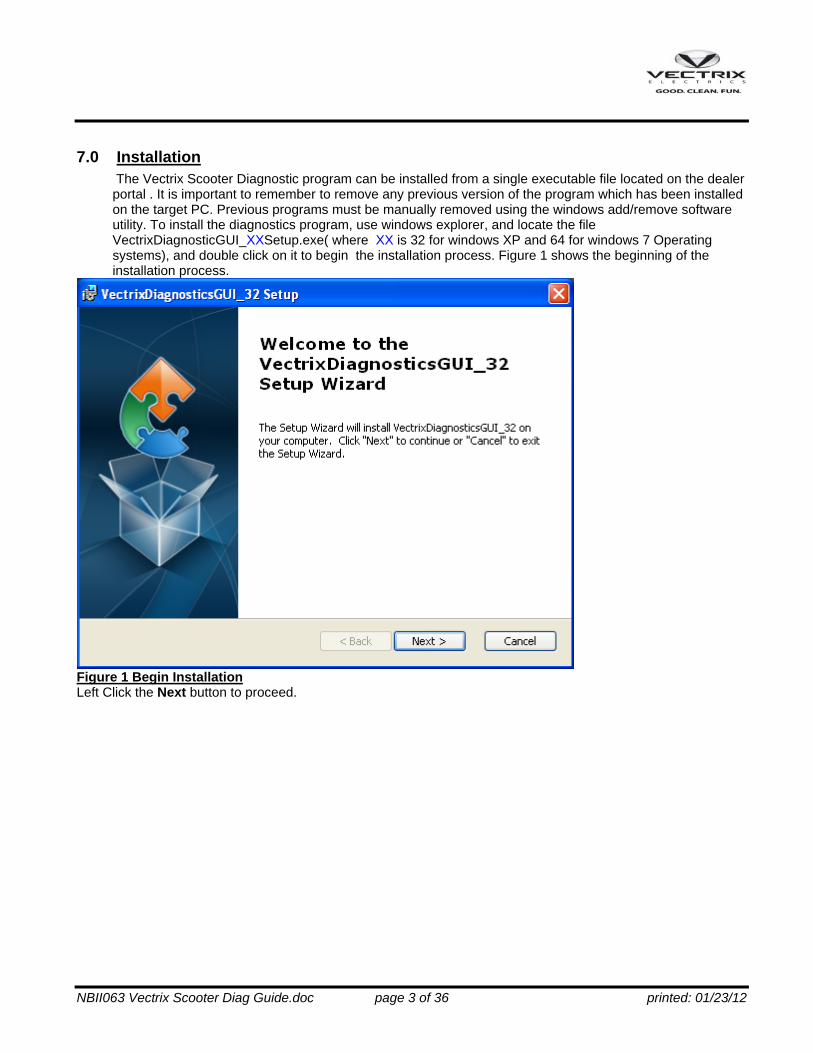
8.3 Firmware Download
Figure 41 VX1Ni firmware download The firmware download page is similar to the VX1Li with the exception that the BMS modules are not present in the system. For details refer to section 6.3 VX1Li Firmware Download. 8.4 CAN Bus Test The CAN bus test is identical to the VX1Li and is documented in section 7.5 8.5 Plot The Plotting function is Identical to the VX1Li with the exception that some of the battery cell voltages are not valid, but motor control, bus current, and bus voltage parameters are valid.

NBII063 Vectrix Scooter Diag Guide.doc page 32 of 36 printed: 01/23/12
8.6 Riding History
Figure 42 VX1Ni Riding History Page The Riding History page is very similar to the VX1Li. The riding history for the VX1Ni does not contain all the parameters that are recorded in the VX1Li. What is available is the On time, Distance, amp hours used during a ride, fuel start , fuel end, and High battery temperature (during a charge state only), and fault code. See appendix B for fault codes.
NBII063 Vectrix Scooter Diag Guide.doc page 33 of 36 printed: 01/23/12
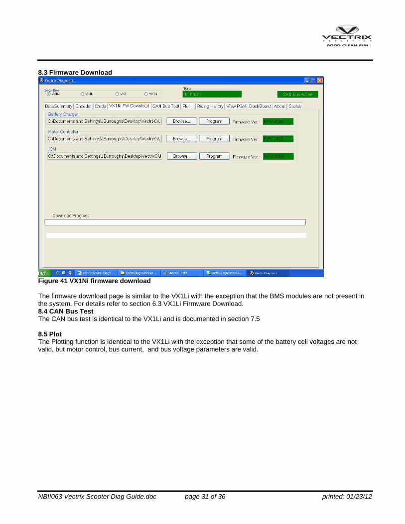
9.0 VX2 The VX2 is a simpler version of Scooter. It does not have the CAN traffic that the VX1 or VX3 scooters have, and thus a limited diagnostic capability. 9.1 Commands The Commands page is identical to the VX1Li commands page documented in section 7.3 9.2 Firmware Download The Firmware download page is similar to the both VX1 download pages, with the exception that the motor controller provides version information upon request. A version Read button was added to the page to request both firmware and parameter revision information. As with the other scooter firmware update pages if you are unsure of the version please contact Vectrix service for assistance.
Figure 43 VX2 firmware download page 9.3 View PGN This page is useful as it can provide the most information about the status of the VX2. A custom VX2 view xml file is provided with the installation, and is titled VX2snoop.xml.. The Screen shot below shows the information available using this utility.

NBII063 Vectrix Scooter Diag Guide.doc page 34 of 36 printed: 01/23/12
Figure 44 View PGN VX2 using custom VX2snoop.xml
10.0 VX3 VX3 functions are Identical to the VX1Li. The tilt component of it will be included at a later date.

NBII063 Vectrix Scooter Diag Guide.doc page 35 of 36 printed: 01/23/12
Appendix A Motor Controller Fault codes. VX1 Li Speedometer err Dash Icon Error Description Bit in
riding history
HS Hot Temp Motor cont Heat sink > 110 C 15 Throttle Wrench Throttle Not Valid 14 noFEF3 Wrench MC does not see BMS Data 13 CAPhot Temp Bus cap hot > 105C 11 EngHot Temp Motor temp > 126C 10 CAPcur Wrench Cap current Fault Cap fuse blown 7 12volt Wrench 12 V Power Fault 6 CAnBuS Wrench Throttle Signal not received 5 Encodr Wrench Encoder fault. Pulse count not
correct 4
uP rst Wrench uP reset 2

NBII063 Vectrix Scooter Diag Guide.doc page 36 of 36 printed: 01/23/12
Appendix B Motor Controller Fault codes. VX1 Ni Speedometer err Dash Icon Error Description Bit in
riding history
HS Hot Temp Motor cont Heat sink > 110 C 15 Throttle Wrench Throttle Not Valid 14 BUSvLt Wrench Low Bus Voltage fault 12 CAPhot Temp Bus cap hot > 105C 11 EngHot Temp Motor temp > 126C 10 Battery Low Bus warning 8 Capcur Wrench Cap current Cap fuse blown 7 CAnBuS Wrench Throttle Signal not received 5 Encodr Wrench Encoder fault. Pulse count not
correct 4
uP rst Wrench uP reset 2