Embed Size (px)
Citation preview

MONTAJES E INSTALACIONES PLASTICAS, S.A. Polígono Industrial Tartessos, Naves 51-99 – 21007 HUELVA (ESPAÑA) Telf. (959) 367 666 / 69 - Fax. (959) 367 674
FEP - DESCRIPCIÓN FEP- DESCRIPTION
Índice
FEP – Descripción
Introducción / Designation 1
Principales Propiedades del FEP/Main Properties
of FEP 2
Estructura y Propiedades Generales del FEP /
Structure and General Properties of FEP 3
Densidad / Density 4
Absorción de Agua / Absortion of Water 5
Impermeabilidad / Impermeability 6
Propiedades Mecánicas / Mechanical Properties 7
Propiedades Térmicas / Thermal Properties 8
Comportamiento del FEP ante el calor / Thermal Behaviour of FEP 9 Propiedades Químicas / Chemical Properties 10
Propiedades Eléctricas / Electrical Properties 11
Propiedades del FEP en comparación con otros
materiales aislantes / Properties of FEP in
comparison with other insulating materials 12
Compuestos de FEP / FEP Compounds 13
Case History 14
FEP – DESCRIPCIÓN 2 / 7
FEP – DESCRIPCIÓN .
INTRODUCCIÓN F.E.P. es un signo internacional abreviado del etileno - propileno - fluorado. Surge por copolimerización del tetrafluoretileno y del hexafluorpropileno. Los núcleos de carbono están totalmente rodeados de átomos de flúor. PRINCIPALES PROPIEDADES DEL F.E.P. Estabilidad química casi absoluta. Únicamente, es atacado por los metales alcalinos fundidos y por ciertos compuestos fluorados o altas presiones y temperaturas. ESTRUCTURA Y PROPIEDADES GENERALES DEL F.E.P. Para obtener una buena calidad de F.E.P., es preciso disminuir al mínimo su porosidad. Una calidad aceptable no ha de poseer una porosidad superior al 1 %. En la tabla puede observarse la gran influencia de la porosidad en la resistencia a la tracción de una pieza terminada.
FIGURA N. 1
CONTENIDO EN POROS RESISTENCIA A LA TRACCIÓN
1 % 154 kg/cm²
0,1 % 182 kg/cm²
casi 0 315 kg/cm²
Lo mismo ocurre con las características dieléctricas, que disminuyen rápidamente al aumentar el contenido de poros (Figura nº 2).
FIGURA N. 2
FIGURA N. 3 Otro factor que hay que tener en cuenta es la cristalinidad. En la figura Nº 3, se relacionan los valores ideales que se pueden conseguir entre la cristalinidad y el peso específico. Cuanto más cristalizado es el polímero, mayor es su densidad.
PROPIEDADES CRISTALINID. VAR.
% 50% 56% Alargamiento permanente en % 250,00 180,00 -30 Compresibilidad en % 22,00 16,00 -30 Deformación permanente a la comprensión % 2,50 1,50 -40
Deformación perman. a la flexión % 5,00 3,30 -30 Resistencia a flexión alternativa (nº de ciclos)
60.000 40.000 -30
Resistencia al choque pieza ent., en m. kg/cm²
4,29 2,14 -30
FEP – DESCRIPTION . DESIGNATION FEP is an international abbreviation for fluorinated ethylene propylene. It is formed by copolymerisation of tetrafluoroethylene with hexafluoropropylene. The carbon atoms are completely surrounded by fluorine atoms. MAIN PROPERTIES OF FEP Chemical stability almost complete. It is only attacked by molten alkali metals and by certain fluorinated compounds or at elevated pressures or temperatures. STRUCTURE AND GENERAL PROPERTIES OF FEP In order to obtain high-quality FEP, its porosity must be lowered as much as possible. An acceptable grade must not exhibit a porosity above 1%. The table shows the strong influence the porosity has on the tensile strength of a finished part.
FIGURE 1
PORE CONTENT TENSILE STRENGTH
1 % 154 kg/cm²
0,1 % 182 kg/cm²
near 0 315 kg/cm²
The same happens with the dielectric properties, which rapidly decrease with increasing pore content (Figure 2).
FIGURE N. 2
FIGURE N. 3 Another factor to keep in mind is the crystallinity. In Figure 3, the ideal crystallinity values obtainable as a function of the specific weight are shown. The higher the crystallinity of the polymer, the higher its density.
PROPERTIES CRYSTALLINITY VAR.
% 50% 56%
Permanent elongation in % 250,00 180,00 -30
Compressibility in % 22,00 16,00 -30
Permanent deform. on compress. % 2,50 1,50 -40
Permanent deform. on bending % 5,00 3,30 -30
Resist. to altern. bending (no. of cycles) 60.000 40.000 -30
Impact r. of the ent. part in kg⋅m/cm2 4,29 2,14 -30
100
200
300
400
500
0 2 4 6 8
RIG
IDEZ
DIE
LECT
RICA
(Vol
t.)
% DE POROS
2,002,042,082,122,162,202,242,282,32
0 20 40 60 70 80
DEN
SID
AD A
23
ºC
CRISTALINIDAD %
100
200
300
400
500
0 2 4 6 8
DIE
LECT
RIC
RIG
IDIT
Y (V
olt)
% OF PORES
2,002,042,082,122,162,202,242,282,32
0 20 40 60 70 80
DEN
SITY
AT
23 º
C
CRYSTALLINITY %
2,16
2,18
2,20
2,22
2,24
300º 375º 400º 425º 450º
DEN
SID
AD
TEMPERATURA DE SINTERIZACIÓN
2,16
2,18
2,20
2,22
2,24
300º 375º 400º 425º 450º
DEN
SITY
SINTERING TEMPERATURE
FEP – DESCRIPCIÓN 3 / 7
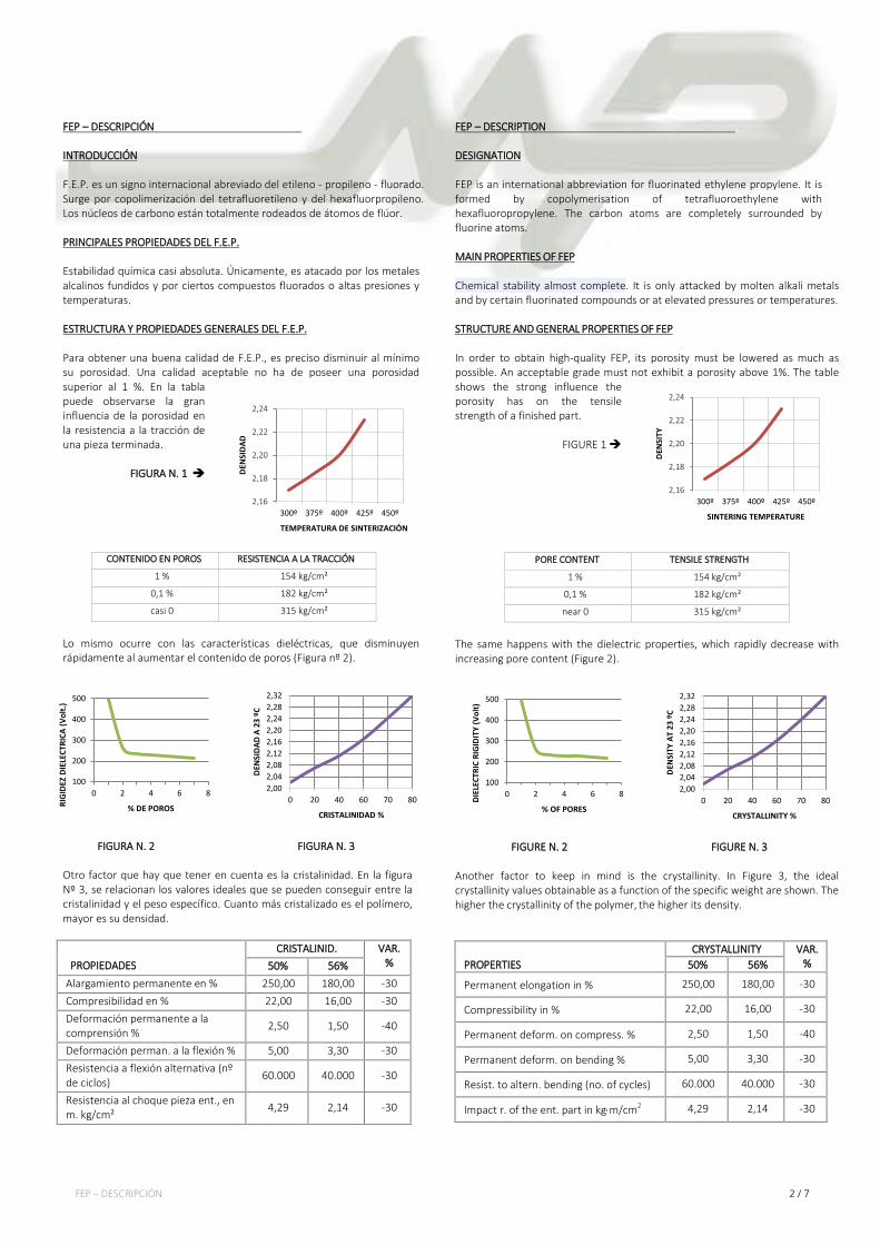
Y en las Figuras 4 y 5, se puede observar la influencia de la cristalinidad sobre la fluencia y el módulo de flexión.
5010x10
30x10
20x10
60 70 9080
40x10
40
-6
-6
-6
-6
70 kg/cm
35 kg/cm
2
2
FLU
EN
CIA
cm
/cm
CRISTALINIDAD %
FIGURA N. 4
FIGURA N. 5 DENSIDAD
La densidad del F.E.P. depende del proceso de fabricación. A temperatura ambiente, es 2,15 aproximadamente. Conforme la temperatura aumenta, la densidad disminuye, tal y como puede apreciarse en la Figura Nº 6.
FIGURA Nº 6
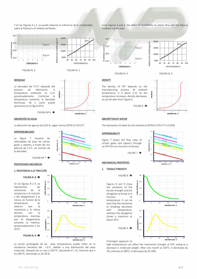
ABSORCIÓN DE AGUA La absorción de agua es de 0,05 %, según norma ASTM-D 570-57T. IMPERMEABILIDAD La figura 7 muestra las velocidades de paso de ciertos gases y vapores, a través de una película de F.E.P., en función de la densidad.
FIGURA Nº 7
PROPIEDADES MECÁNICAS
1. RESISTENCIA A LA TRACCIÓN
FIGURA N. 8
En las figuras 8 y 9, se representan las variaciones de la resistencia a la tracción y del alargamiento a la rotura, en función de la temperatura. Se observa que la resistencia a la rotura decrece con la temperatura, mientras que el alargamiento presenta un máximo, aproximadamente a los 20 ºC.
FIGURA N. 9
La acción prolongada de las altas temperaturas puede influir en la resistencia mecánica del F.E.P., debido a una disminución del peso molecular. Después de un mes a 250 ºC, desciende el 1 %, mientras que a los 300 ºC, desciende un 20-30 %.
From Figures 4 and 5, the effect of crystallinity on plastic flow and the flexural modulus can be seen.
5010x10
30x10
20x10
60 70 9080
40x10
40
-6
-6
-6
-6
70 kg/cm
35 kg/cm
2
2
FLU
EN
CIA
cm
/cm
CRISTALINIDAD %
FIGURA N. 4
FIGURA N. 5 DENSITY The density of FEP depends on the manufacturing process. At ambient temperature, it is about 2,15. As the temperature increases, density decreases, as can be seen from Figure 6.
FIGURE 6
ABSORPTION OF WATER The absorption of water by the method of ASTM-D 570-57T is 0.05%.
IMPERMEABILITY Figure 7 shows the flow rates of certain gases and vapours through an FEP film as a function of density.
FIGURE 7
MECHANICAL PROPERTIES 1. TENSILE STRENGTH
FIGURE 8
Figures 8 and 9 show the variations of the tensile strength and the elongation at break as a function of temperature. It can be seen that the resistance to breaking decreases with temperature, whereas the elongation shows a maximum at about 20°C.
FIGURE 9
Prolonged exposure to high temperatures can affect the mechanical strength of FEP, owing to a decrease in molecular weight. After one month at 250°C, it decreases by 1%, whereas at 300°C, it decreases by 20-30%.
5000
10000
15000
20000
40 50 60 70 80 90 100
MÓ
DULO
DE
FLEX
IÓN
(kg/
cm²)
CRISTALINIDAD % 5000
10000
15000
20000
40 50 60 70 80 90 100
MÓ
DULO
DE
FLEX
IÓN
(kg/
cm²)
CRISTALINIDAD %
DEN
SIDA
D
TEMPERATURA ºC
41ºC
0,01
0,0012,14
1
0,1
2,16 2,18 2,20 2,22 2,24
10
100
Cl H 30ºC
Nitrogeno a 30ºC
Helio 30ºC
CO2 30ºC
Agua (Vapor) 100 ºC
DENSIDAD A 23 ºC
PERM
EABI
LIDA
D /
DIA
0-50 500 100
200
100
300
150 200
400
0-50
100
200
0 50 100 150 200
300
400
TEMPERATURA ºC
CARG
A RO
TURA
kg/c
m²
TEMPERATURA ºC
ALAR
GAM
IENTO
%
DEN
SIDA
D
TEMPERATURA ºC
0,01
0,0012,14
1
0,1
2,16 2,18 2,20 2,22 2,24
10
100
Cl H 30ºC
Nitrogeno a 30ºC
Helio 30ºC
CO2 30ºC
Agua (Vapor) 100 ºC
DENSIDAD A 23 ºC
PERM
EABI
LIDA
D /
DIA
41ºC
0-50 500 100
200
100
300
150 200
400
0-50
100
200
0 50 100 150 200
300
400
TEMPERATURA ºC
CARG
A RO
TURA
kg/c
m²
TEMPERATURA ºC
ALAR
GAM
IENTO
%
FEP – DESCRIPCIÓN 4 / 7
2. EFLUENCIA Y RESISTENCIA A LA COMPRESIÓN
FIGURA Nº 10
0
1
2
3
4
4020 60 80 100 120 140 160
5
6
Fluencia
Deformación Instantanea
Regresión Instantanea
Regresión Retardada
Deformación Permanente
Fin de la Compresión
TIEMPO EN HORAS
DEFO
RMAC
IÓN
%
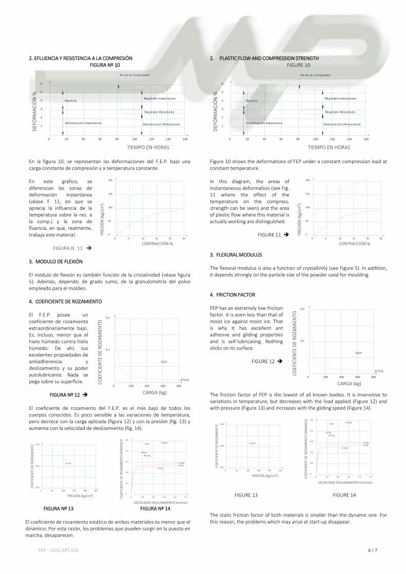
En la figura 10, se representan las deformaciones del F.E.P. bajo una carga constante de compresión y a temperatura constante. En este gráfico, se diferencian las zonas de deformación instantánea (véase f. 11, en que se aprecia la influencia de la temperatura sobre la res. a la comp.) y la zona de fluencia, en que, realmente, trabaja este material.
FIGURA N. 11 3. MODULO DE FLEXIÓN El módulo de flexión es también función de la cristalinidad (véase figura 5). Además, depende, de grado sumo, de la granulometría del polvo empleado para el moldeo.
4. COEFICIENTE DE ROZAMIENTO El F.E.P. posee un coeficiente de rozamiento extraordinariamente bajo. Es, incluso, menor que el hielo húmedo contra hielo húmedo. De ahí, sus excelentes propiedades de antiadherencia y deslizamiento y su poder autolubricante. Nada se pega sobre su superficie.
FIGURA Nº 12 El coeficiente de rozamiento del F.E.P. es el más bajo de todos los cuerpos conocidos. Es poco sensible a las variaciones de temperatura, pero decrece con la carga aplicada (figura 12) y con la presión (fig. 13) y aumenta con la velocidad de deslizamiento (fig. 14).
0,010 10050 150
0,02
200 250
0,03
P.T.F.E.
0,30
0
0,4
0,2
0,6 0,9 1,51,2
0,1
0,3
0,5
F.E.P.
P.T.F.E.34 kg.0,7 kg.
45,5 kg.4,5 kg.
0,45 kg.
PRESIÓN (kg/cm²)
COEF
ICIE
NTE
DE
ROZA
MIE
NTO
VELOCIDAD DESLIZAMIENTO (m/min)
COEF
ICIE
NTE
DE
ROZA
MIE
NTO
DIN
ÁMIC
O
FIGURA Nº 13 FIGURA Nº 14 El coeficiente de rozamiento estático de ambos materiales es menor que el dinámico. Por esta razón, los problemas que pueden surgir en la puesta en marcha, desaparecen.
2. PLASTIC FLOW AND COMPRESSION STRENGTH
FIGURE 10
0
1
2
3
4
4020 60 80 100 120 140 160
5
6
Fluencia
Deformación Instantanea
Regresión Instantanea
Regresión Retardada
Deformación Permanente
Fin de la Compresión
TIEMPO EN HORAS
DEFO
RMAC
IÓN
%
Figure 10 shows the deformations of FEP under a constant compression load at constant temperature. In this diagram, the areas of instantaneous deformation (see Fig. 11 where the effect of the temperature on the compress. strength can be seen) and the area of plastic flow where this material is actually working are distinguished.
FIGURE 11
3. FLEXURAL MODULUS The flexural modulus is also a function of crystallinity (see Figure 5). In addition, it depends strongly on the particle size of the powder used for moulding. 4. FRICTION FACTOR FEP has an extremely low friction factor. It is even less than that of moist ice against moist ice. That is why it has excellent ant adhesive and gliding properties and is self-lubricating. Nothing sticks on its surface.
FIGURE 12 The friction factor of FEP is the lowest of all known bodies. It is insensitive to variations in temperature, but decreases with the load applied (Figure 12) and with pressure (Figure 13) and increases with the gliding speed (Figure 14).
0,010 10050 150
0,02
200 250
0,03
P.T.F.E.
0,30
0
0,4
0,2
0,6 0,9 1,51,2
0,1
0,3
0,5
F.E.P.
P.T.F.E.34 kg.0,7 kg.
45,5 kg.4,5 kg.
0,45 kg.
PRESIÓN (kg/cm²)
COEF
ICIE
NTE
DE
ROZA
MIE
NTO
VELOCIDAD DESLIZAMIENTO (m/min)
COEF
ICIE
NTE
DE
ROZA
MIE
NTO
DIN
ÁMIC
O
FIGURE 13 FIGURE 14 The static friction factor of both materials is smaller than the dynamic one. For this reason, the problems which may arise at start-up disappear.
00 105 15
100
50
150
20 25
200
CONTRACCIÓN %
PRES
IÓN
(kg/
cm²)
0
0,1
200 400 600 800
0,2
F.E.P.
P.T.F.E.
CARGA (kg)
COEF
ICIE
NTE
DE
ROZA
MIE
NTO
00 105 15
100
50
150
20 25
200
CONTRACCIÓN %
PRES
IÓN
(kg/
cm²)
0
0,1
200 400 600 800
0,2
F.E.P.
P.T.F.E.
CARGA (kg)
COEF
ICIE
NTE
DE
ROZA
MIE
NTO
FEP – DESCRIPCIÓN 5 / 7
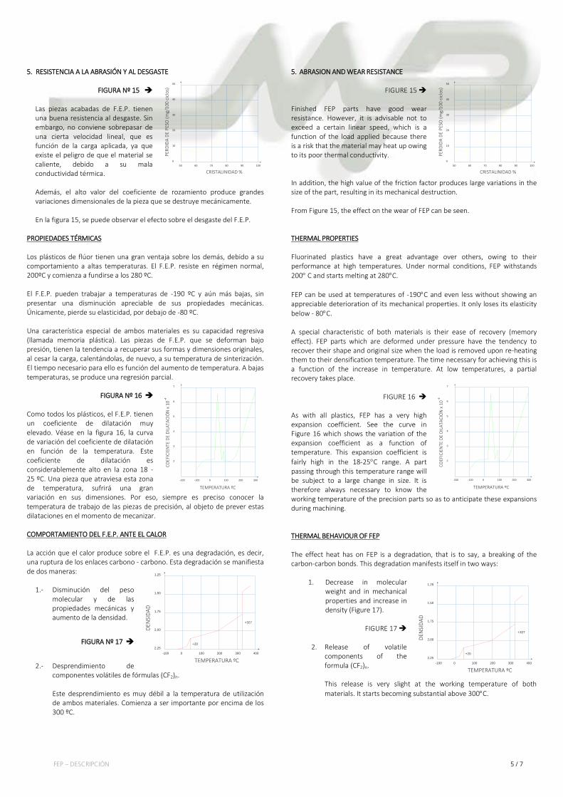
5. RESISTENCIA A LA ABRASIÓN Y AL DESGASTE
FIGURA Nº 15
Las piezas acabadas de F.E.P. tienen una buena resistencia al desgaste. Sin embargo, no conviene sobrepasar de una cierta velocidad lineal, que es función de la carga aplicada, ya que existe el peligro de que el material se caliente, debido a su mala conductividad térmica.
Además, el alto valor del coeficiente de rozamiento produce grandes variaciones dimensionales de la pieza que se destruye mecánicamente. En la figura 15, se puede observar el efecto sobre el desgaste del F.E.P.
PROPIEDADES TÉRMICAS
Los plásticos de flúor tienen una gran ventaja sobre los demás, debido a su comportamiento a altas temperaturas. El F.E.P. resiste en régimen normal, 200ºC y comienza a fundirse a los 280 ºC.
El F.E.P. pueden trabajar a temperaturas de -190 ºC y aún más bajas, sin presentar una disminución apreciable de sus propiedades mecánicas. Únicamente, pierde su elasticidad, por debajo de -80 ºC.
Una característica especial de ambos materiales es su capacidad regresiva (llamada memoria plástica). Las piezas de F.E.P. que se deforman bajo presión, tienen la tendencia a recuperar sus formas y dimensiones originales, al cesar la carga, calentándolas, de nuevo, a su temperatura de sinterización. El tiempo necesario para ello es función del aumento de temperatura. A bajas temperaturas, se produce una regresión parcial.
FIGURA Nº 16
Como todos los plásticos, el F.E.P. tienen un coeficiente de dilatación muy elevado. Véase en la figura 16, la curva de variación del coeficiente de dilatación en función de la temperatura. Este coeficiente de dilatación es considerablemente alto en la zona 18 - 25 ºC. Una pieza que atraviesa esta zona de temperatura, sufrirá una gran variación en sus dimensiones. Por eso, siempre es preciso conocer la temperatura de trabajo de las piezas de precisión, al objeto de prever estas dilataciones en el momento de mecanizar. COMPORTAMIENTO DEL F.E.P. ANTE EL CALOR
La acción que el calor produce sobre el F.E.P. es una degradación, es decir, una ruptura de los enlaces carbono - carbono. Esta degradación se manifiesta de dos maneras:
1.- Disminución del peso
molecular y de las propiedades mecánicas y aumento de la densidad.
FIGURA Nº 17
2.- Desprendimiento de componentes volátiles de fórmulas (CF2)n.
Este desprendimiento es muy débil a la temperatura de utilización de ambos materiales. Comienza a ser importante por encima de los 300 ºC.
5. ABRASION AND WEAR RESISTANCE
FIGURE 15 Finished FEP parts have good wear resistance. However, it is advisable not to exceed a certain linear speed, which is a function of the load applied because there is a risk that the material may heat up owing to its poor thermal conductivity.
In addition, the high value of the friction factor produces large variations in the size of the part, resulting in its mechanical destruction.
From Figure 15, the effect on the wear of FEP can be seen.
THERMAL PROPERTIES Fluorinated plastics have a great advantage over others, owing to their
performance at high temperatures. Under normal conditions, FEP withstands 200° C and starts melting at 280°C.
FEP can be used at temperatures of -190°C and even less without showing an
appreciable deterioration of its mechanical properties. It only loses its elasticity below - 80°C. A special characteristic of both materials is their ease of recovery (memory effect). FEP parts which are deformed under pressure have the tendency to recover their shape and original size when the load is removed upon re-heating them to their densification temperature. The time necessary for achieving this is a function of the increase in temperature. At low temperatures, a partial recovery takes place.
FIGURE 16 As with all plastics, FEP has a very high expansion coefficient. See the curve in Figure 16 which shows the variation of the expansion coefficient as a function of temperature. This expansion coefficient is fairly high in the 18-25°C range. A part passing through this temperature range will be subject to a large change in size. It is therefore always necessary to know the working temperature of the precision parts so as to anticipate these expansions during machining. THERMAL BEHAVIOUR OF FEP The effect heat has on FEP is a degradation, that is to say, a breaking of the carbon-carbon bonds. This degradation manifests itself in two ways:
1. Decrease in molecular weight and in mechanical properties and increase in density (Figure 17).
FIGURE 17
2. Release of volatile components of the formula (CF2)n.
This release is very slight at the working temperature of both materials. It starts becoming substantial above 300°C.
50
20
60 70 80 90
40
100
10
0
30
50
CRISTALINIDAD %PE
RDID
A DE
PES
O (m
g/10
0 ci
clos
)
-100-200
5
3
0 100 300200
2
4
6
-4
7
TEMPERATURA ºC
COEF
ICIE
NTE
DE
DILA
TACI
ÓN
x 1
0
-100
1,25
1,75
0 100 300200
2,00
1,50
2,25400
+20
+327
TEMPERATURA ºC
DEN
SIDA
D
50
20
60 70 80 90
40
100
10
0
30
50
CRISTALINIDAD %
PERD
IDA
DE P
ESO
(mg/
100
cicl
os)
-100-200
5
3
0 100 300200
2
4
6
-4
7
TEMPERATURA ºC
COEF
ICIE
NTE
DE
DILA
TACI
ÓN
x 1
0
-100
1,25
1,75
0 100 300200
2,00
1,50
2,25400
+20
+327
TEMPERATURA ºC
DEN
SIDA
D
FEP – DESCRIPCIÓN 6 / 7
2000,0001
0,0005
250225 275
0,01
0,002
0,05
300 325 350 375 400 425 450
0,0002
0,005
0,02
0,2
0,5
1
TEMPERATURA ºC
PERD
IDA
DE P
ESO
(% /
HORA
S)
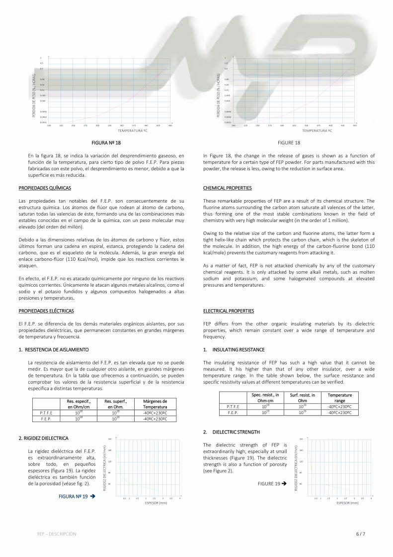
FIGURA Nº 18 En la figura 18, se indica la variación del desprendimiento gaseoso, en función de la temperatura, para cierto tipo de polvo F.E.P. Para piezas fabricadas con este polvo, el desprendimiento es menor, debido a que la superficie es más reducida.
PROPIEDADES QUÍMICAS
Las propiedades tan notables del F.E.P. son consecuentemente de su estructura química. Los átomos de flúor que rodean al átomo de carbono, saturan todas las valencias de éste, formando una de las combinaciones más estables conocidas en el campo de la química, con un peso molecular muy elevado (del orden del millón).
Debido a las dimensiones relativas de los átomos de carbono y flúor, estos últimos forman una cadena en espiral, estanca, protegiendo la cadena del carbono, que es el esqueleto de la molécula. Además, la gran energía del enlace carbono-flúor (110 Kcal/mol), impide que los reactivos corrientes le ataquen.
En efecto, el F.E.P. no es atacado químicamente por ninguno de los reactivos químicos corrientes. Únicamente le atacan algunos metales alcalinos, como el sodio y el potasio fundidos y algunos compuestos halogenados a altas presiones y temperaturas. PROPIEDADES ELÉCTRICAS
El F.E.P. se diferencia de los demás materiales orgánicos aislantes, por sus propiedades dieléctricas, que permanecen constantes en grandes márgenes de temperatura y frecuencia. 1. RESISTENCIA DE AISLAMIENTO
La resistencia de aislamiento del F.E.P. es tan elevada que no se puede medir. Es mayor que la de cualquier otro aislante, en grandes márgenes de temperatura. En la tabla que ofrecemos a continuación, se pueden comprobar los valores de la resistencia superficial y de la resistencia específica a distintas temperaturas.
Res. especif., en Ohm/cm
Res. superf., en Ohm.
Márgenes de Temperatura
P.T.F.E 1018 1016 -40ºC+230ºC F.E.P. 1018 1016 -40ºC+230ºC
2. RIGIDEZ DIELECTRICA La rigidez dieléctrica del F.E.P. es extraordinariamente alta, sobre todo, en pequeños espesores (figura 19). La rigidez dieléctrica es también función de la porosidad (véase fig. 2).
FIGURA Nº 19
2000,0001
0,0005
250225 275
0,01
0,002
0,05
300 325 350 375 400 425 450
0,0002
0,005
0,02
0,2
0,5
1
TEMPERATURA ºC
PERD
IDA
DE P
ESO
(% /
HORA
S)
FIGURE 18
In Figure 18, the change in the release of gases is shown as a function of temperature for a certain type of FEP powder. For parts manufactured with this powder, the release is less, owing to the reduction in surface area. CHEMICAL PROPERTIES These remarkable properties of FEP are a result of its chemical structure. The fluorine atoms surrounding the carbon atom saturate all valences of the latter, thus forming one of the most stable combinations known in the field of chemistry with very high molecular weight (in the order of 1 million). Owing to the relative size of the carbon and fluorine atoms, the latter form a tight helix-like chain which protects the carbon chain, which is the skeleton of the molecule. In addition, the high energy of the carbon-fluorine bond (110 kcal/mole) prevents the customary reagents from attacking it. As a matter of fact, FEP is not attacked chemically by any of the customary chemical reagents. It is only attacked by some alkali metals, such as molten sodium and potassium, and some halogenated compounds at elevated pressures and temperatures. ELECTRICAL PROPERTIES FEP differs from the other organic insulating materials by its dielectric properties, which remain constant over a wide range of temperature and frequency. 1. INSULATING RESISTANCE The insulating resistance of FEP has such a high value that it cannot be measured. It his higher than that of any other insulator, over a wide temperature range. In the table shown below, the surface resistance and specific resistivity values at different temperatures can be verified.
Spec. resist., in Ohm⋅cm
Surf. resist. in Ohm
Temperature range
P.T.F.E 1018 1016 -40ºC+230ºC F.E.P. 1018 1016 -40ºC+230ºC
2. DIELECTRIC STRENGTH The dielectric strength of FEP is extraordinarily high, especially at small thicknesses (Figure 19). The dielectric strength is also a function of porosity (see Figure 2).
FIGURE 19
40
120
80
160
0,5
200
1 1,5 2 2,5 3 3,5 4
ESPESOR (mm)
RIG
IDEZ
DIE
LECT
RICA
(kV/
mm
)
40
120
80
160
0,5
200
1 1,5 2 2,5 3 3,5 4
ESPESOR (mm)
RIG
IDEZ
DIE
LECT
RICA
(kV/
mm
)
FEP – DESCRIPCIÓN 7 / 7
PROPIEDADES DEL F.E.P. EN COMPARACIÓN CON OTROS MATERIALES AISLANTES
MATERIAL Res.
espec. Ohm/cm
Const. dielect.
Factor de perd.
Rigid. dielect. KV/mm
Abs. agua %
Temp. trab. ºC
F.E.P. puro 1018 2,1 0,0003 20-40 0,01 250
Tejido de vidrio impregnado F.E.P.
1015 3 0,001 20-30 0,05 250
Papel prens. 1012-1014 4,5 0,05 20-29 1 110
Tejido prensado
1010-1012 5 0,2 6-36 2 110
COMPUESTOS DE F.E.P.
El F.E.P. se puede mezclar con otros materiales, como fibra de vidrio, grafito, carbón, bisulfuro de molibdeno, cobre, bronce, productos cerámicos, etc., con objeto de conseguir la mejora de ciertas de sus propiedades:
- Disminución de la fluencia en frío. - Disminución del coeficiente de dilatación. - Mayor conductibilidad térmica. - Mayor resistencia al desgaste y mayor deslizamiento. - Mejores características mecánicas.
PROPERTIES OF FEP IN COMPARISON WITH OTHER INSULATING MATERIALS
MATERIAL
Spec. resist. Ohm⋅
cm Dielect. constant
Loss factor
Dielect. strength kV/mm
Absorp. of water
%
Work. temp. °C
Pure FEP 1018 3 2,1 0,0003 20-40 0,01 250
FEP impr. with glass fabric
1015 3 0,001 20-30 0,05 250
Press. paper 1012-1014
4,5 0,05 20-29 1 110
Press. fabric 1010-1012
5 0,2 6-36 2 110
FEP COMPOUNDS FEP can be mixed with other materials, such as glass fibre, graphite, carbon,
molybdenum disulfide, copper, bronze, ceramic products, and the like, in order to achieve an improvement in certain of its properties:
- Decrease in plastic flow in the cold - Decrease in the expansion coefficient - Better thermal conductivity - Better wear resistance and better gliding - Better mechanical properties