Embed Size (px)
Citation preview
Near-surface mounted carbon fibre rod used for combined strengthening and cathodic protection for reinforced concrete structures
NGUYEN, Chinh, LAMBERT, Paul, MANGAT, Pal <http://orcid.org/0000-0003-1736-8891>, O'FLAHERTY, Fin <http://orcid.org/0000-0003-3121-0492> and JONES, Graeme
Available from Sheffield Hallam University Research Archive (SHURA) at:
http://shura.shu.ac.uk/9476/
This document is the author deposited version. You are advised to consult the publisher's version if you wish to cite from it.
Published version
NGUYEN, Chinh, LAMBERT, Paul, MANGAT, Pal, O'FLAHERTY, Fin and JONES, Graeme (2015). Near-surface mounted carbon fibre rod used for combined strengthening and cathodic protection for reinforced concrete structures. Structure and Infrastructure Engineering, 12 (3), 356-365.
Copyright and re-use policy
See http://shura.shu.ac.uk/information.html
Sheffield Hallam University Research Archivehttp://shura.shu.ac.uk

Near-surface mounted carbon fibre rod used for combined
strengthening and cathodic protection for reinforced concrete
structures
Chinh Van Nguyen
Centre for Infrastructure Management, Materials and Engineering Research Institute, Sheffield Hallam University, Sheffield S1 1WB, UK
Email: [email protected]
Tel: +44 (0) 114 225 4081
Paul Lambert
Centre for Infrastructure Management, Materials and Engineering Research Institute, Sheffield Hallam University, Sheffield S1 1WB, UK
Email: [email protected]
Tel: +44 (0) 114 225 3501
Pritpal S. Mangat
Centre for Infrastructure Management, Materials and Engineering Research Institute, Sheffield Hallam University, Sheffield S1 1WB, UK
Email: [email protected]
Tel: +44 (0) 114 225 3501
Fin J. O’Flaherty
Centre for Infrastructure Management, Materials and Engineering Research Institute, Sheffield Hallam University, Sheffield S1 1WB, UK
Email: [email protected]
Tel: +44 (0) 114 225 3501
Graeme Jones
C-Probe Systems Ltd., Blackmoss Court, Blackmoss Road, Dunham Massey, Cheshire WA145RG, UK
Email:[email protected]
Tel: +44 (0) 161 928 1101
Full correspondence details: Chinh Van Nguyen, Materials and Engineering Research Institute, Sheffield Hallam University, Sheffield S1 1WB, UK
Email: [email protected]
Near-surface mounted carbon fibre rod used for combined
strengthening and cathodic protection for reinforced concrete
structures
The dual function of a carbon fibre reinforced polymer (CFRP) rod
working as the near surface mounted (NSM) strengthening and impressed
current cathodic protection (ICCP) anode for corroded reinforced concrete
structures has been proposed and researched. In this paper, a CFRP rod
was used for both flexural strengthening of pre-corroded reinforced
concrete beams and in a dual functional capacity as an ICCP anode. After a
period of ICCP operation at high current density, the beams were subjected
to flexural testing to determine the load-deflection relationships. The
potential decays of the steel met recognised ICCP standards and the CFRP
remained effective in strengthening the corroded reinforced concrete
beams. The bonding at the CFRP rod anode and concrete interface was
improved by using a combination of geopolymer and epoxy resin,
therefore the ultimate strength of a dual function CFRP rod with
combination of bonding medium (geopolymer and epoxy) increased
significantly.
Keywords: Near surface mounted (NSM), CFRP rod, strengthening,
cathodic protection, anode, geopolymer.
1. Introduction
Corrosion of embedded steel can eventually lead to the deterioration of concrete
structures and reduction in their service life (Lambert, 2002; Rodriguez, Ortega &
Casal, 1994; McLeish, 1987; Ahmad, 2003). Near surface mounted (NSM) FRP
bar is one of the promising developments for strengthening of deteriorated
reinforced concrete elements (Asplund, 1949; El-Hacha, Rizkalla, 2004). There
are many advantages with NSM FRP when compared to externally bonded FRP
(De Lorenzis & Teng, 2007). Site working may be reduced because of less
onerous surface preparation. Debonding of NSM FRP is less than that of
externally bonded FRP. NSM reinforcement can also be more easily pre-stressed.

NSM FRPs are largely protected by the concrete cover and, therefore, are less
exposed to accidental impact and mechanical damage, fire and vandalism. In
addition, the aesthetics of members strengthened by NSM remain essentially
unchanged.
Cathodic protection (CP) has been proven to be an effective method for
preventing and protecting reinforced concrete structures from corrosion (Lambert,
1995; Haldemann & Schreyer, 1998; US Federal Highway Administration, 1982;
Pedeferri, 1996). The anode systems employed play an important role in the
success of CP operation. There are a variety of anodes which are currently used
for CP systems in such applications including conductive carbon loaded paints,
thermal sprayed zinc or aluminium alloys. The most widely used anode systems
are based on mixed metal oxide (MMO) coated titanium in mesh, ribbon or rod
configurations. Titanium oxide (titania) is also used in rod form for discrete
anodes (The Concrete Society, 2012).
Previous research has demonstrated that a carbon fibre reinforced polymer
(CFRP) rod can be used as the ICCP anode for reinforced concrete beams when it
is bonded by geopolymer (Nguyen, et al 2012). This paper develops the technique
in which a CFRP rod is employed for NSM strengthening and simultaneously as
an ICCP anode for corroded reinforced concrete beams.
2. Experimental programme
The test programme consisted of 12 beams, divided into two groups as shown in
Table 1. For each group, five beams were subjected to accelerated corrosion to a
pre-degree of 2.5% of diameter loss of the steel bars. The sixth element was the
un-corroded control beam. Group 1 had 6 beams to evaluate the effect of the dual
function CFRP rod anode and strengthening element with a geopolymer

composition used to bond the CFRP rod into a grooved soffit (see Section 2.1).
Beam 1.1 was an un-corroded control beam while Beam 1.2 was a corroded
control which was accelerated to a 2.5% degree of corrosion, but without either
NSM CFRP strengthening or ICCP application. Beams 1.3 and 1.4 were
strengthened with CFRP rod bonded into the grooved soffit by geopolymer only
(strengthening only). Beams 1.5 and 1.6 were dual function beams as CFRP rod
was used for both strengthening and as an ICCP anode for the pre-corroded
beams.
Group 2 had six beams to evaluate the influence of using epoxy with the
geopolymer as a means of improving the bond between the CFRP rod anode and
the concrete interface. These beams followed a similar test pattern to Group 1.
Beam 2.1 was an un-corroded control while Beam 2.2 was a corroded control
which was accelerated to a 2.5% degree of corrosion, but without either NSM
CFRP strengthening or ICCP application. Beams 2.3 and 2.4 were reinforced with
CFRP rod bonded into the grooved soffit of the beam by a combination of
geopolymer and epoxy with the single purpose of increasing the strength. Beams
2.5 and 2.6 were dual function beams as CFRP rod was bonded into the grooved
soffit by a combination of geopolymer and epoxy for strengthening and were also
operated as ICCP anodes for pre-corroded beams.
2.1 Test specimens
The specimens were designed as under-reinforced concrete beams, each 900mm
long with a rectangular cross-section 150 mm depth and 100mm width. Failures
of under reinforced beams are ductile and require large deformations that can
serve as a warning. Longitudinal steel bars were provided to resist the tensile
forces in the bottom of the beam due to bending in accordance with BS EN 1992-
1-1:2004 (British Standard Institute, 2004). Each beam was reinforced by two

plain steel bars of 10 mm diameter. There was no shear reinforcement (Figure 1).
This was aimed to avoid any effects of shear steel bars in accelerating corrosion of
longitudinal reinforcement. All beams were designed for flexural failures;
therefore, premature shear failure was prevented through the use of external steel
collars during flexural testing. Each steel collar included 2 mild steel plates each
dimensions of 210 x 200x 10 (mm) and 2 mild steel plates each dimensions of
270x 150x 10 (mm). Details of the steel collars are shown in Figure 2. The
dimensions of the groove in Figure 1 were selected in accordance with ACI
440.2R-08 (2008) “Guide for the design and construction of externally bonded
FRP systems for strengthening concrete structures” (American Concrete Institute,
2008).
2.2 Material properties
The 28 day compressive strength of the concrete ranged from 37.3MPa to
40.4MPa for Group 1 and from 31.2MPa to 35.3MPa for Group 2. There is
considerable variability between groups and this is considered to be due to a
number of factors such as variability in compaction, moisture content of the
aggregates, curing and possible residual water in the mixer. However, as the
beams were designed for failure by yielding of the reinforcing steel, this variation
in compressive strength of the concrete should not adversely affect the flexural
test results. Plain reinforcement bars of diameter 10mm with a yield strength of
250MPa were used.
The epoxy adhesive was supplied by Sika Corporation (US). In this test,
Sikadur300 adhesive was used, which is a two-component 100% solids, moisture-
tolerant, high strength, high modulus epoxy widely used in CFRP strengthening
applications. It is documented by the manufacturer that Sikadur300 is used as a
seal coat and impregnating resin for horizontal and vertical applications. The
flexural strength and modulus was 79MPa and 3450MPa respectively.
The CFRP rod was Sika CarboDur Rod designed for strengthening
concrete, timber and masonry structures with a tensile strength of 2800MPa,
elongation at break of 1.8% and tensile modulus of elasticity of 155GPa.
A carbon fibre filled geopolymer developed at Sheffield Hallam
University was used to bond the CFRP rods into the grooved reinforced concrete
beams. The mean compressive strength and tensile strength at 28 day age of the
fibre filled geopolymer was 46.3MPa and 2.9MPa respectively.
2.3 Accelerated corrosion
At 21 days after casting, 5 beams from each group were subjected to accelerated
corrosion of the reinforcing steel using an anodic impressed current method. A
current density of 1mA/cm2 was applied to simulate general corrosion of
reinforcing steel. This current density was previously adopted in earlier
experiments (O'Flaherty, Mangat, Lambert & Browne, 2008), and was found to
provide an appropriate level of corrosion, similar in nature and composition to the
naturally occurring process but within a reasonable timescale. The period of
current application was 94 hours to achieve nominal degree of corrosion of 2.5%
of diameter loss. The layout of the corrosion set up is shown in Figure 3. The
current was provided by a DC power supply. The polarity of the current was such
that the steel reinforcement served as the anode and a stainless steel plate worked
as the cathode. The corrosion process took place in a polymer tank where 3.5%
NaCl solution was used as the electrolyte. The solution level in the tank was
adjusted to ensure adequate submersion of the steel bars, while ensuring sufficient
oxygen for the corrosion process to proceed.

For each beam, the current density and corrosion period were adjusted to give the
required degree of corrosion according to Faraday’s Law. The percent reduction
in reinforcing bar diameter in T years, (%)1002 D
RT, was defined as the degree
of reinforcement corrosion in which R (cm/year) is the metal section loss per year,
D (cm) is the diameter of the steel bar (see Table 1) (O'Flaherty, et al 2008). The
current supplied to each beam was checked daily and any drift was corrected.
2.4 Application of CFRPs
The first group using CFRP rod utilised a pre-formed groove on the tension soffit
of the concrete beams using geopolymer only (Figure 1a). The groove was half
filled with the geopolymer, the CFRP rod was placed inside the groove and
further geopolymer was added to completely fill the groove (see Figure 4).
For the second group, the CFRP rod was bonded to the pre-cut groove by
two layers of repair material. A schematic of repair is shown in Figure 1b. Firstly,
the CFRP rods were bonded into the grooves by geopolymer (Figure 5a). The
geopolymer repair was cured in the ambient laboratory conditions for 7 days at
which time epoxy was overlaid as the second repair material (Figure 5b). The
purpose of the epoxy layer was to improve the bond between the CFRP rod anode
and repair material. This is the difference between Groups 1 and 2 and should
have some influence on the improvement in strength capacity due to the greater
elasticity of the epoxy compared to the brittle nature of the geopolymer at the
zone of greatest tensile stress. These samples were cured in the laboratory
environment for a further 21 days prior to ICCP application.
2.5 Application of impressed current cathodic protection (ICCP)
ICCP was applied to the corroded reinforced concrete beams by connecting the
reinforcing steel to the negative terminal and the CFRPs anode to the positive

terminal of a multi-channel power supply. The schematic of ICCP application is
shown in Figure 6. The system was cathodically protected at room temperature
(nominally 20oC) and 60% relative humidity (plus or minus 5%). These
conditions ensured the resistivity of the concrete remained high, representing a
dry site environment. The applied current densities were 64.2mA/m2 of steel
surface area for Beams 1.5 and 1.6 (Group 1-Table 1) and were varied between
125mA/m2 and 310mA/m2 of steel surface area for Beams 2.5 and 2.6 (Group 2-
Table 1). The current was checked and the on and instant -off potentials of the
embedded steel were recorded daily.
3. Results and discussion
3.1 Cathodic protection monitoring
3.1.1 Group 1: Test Beams 1.5 and 1.6
During the 1026 hours (corresponding to approximately 43 days) of operation of
ICCP (Figure 7), the on- potential and potential decays of steel bars were recorded
using embedded Ag/AgCl/0.5M KCl reference electrodes and a high impedance
digital voltmeter (DVM). The ICCP was interrupted three times at 138 hours, 330
hours and 1026 hours, respectively. Although ICCP was achieved at each
interruption (138 and 330 hours) the ICCP was re-run again to investigate the long
term performance of dual function CFRP rod. At 330 hours, the ICCP was
interrupted for 241 hours before it was restarted at 571 hours and continued to
1026 hours. The potential decays at these three occasions were monitored and are
shown in Table 2.
3.1.2 Group 2: Test Beams 2.5 and 2.6
The applied currents to Beams 2.5 and 2.6 were recorded and plotted in Figure 8.
The applied current densities for both beams were around 125mA/m2 for

approximately 100 hours before this was increased to around 280mA/m2 to ensure
adequate polarisation of the steel. The potential drop defined as difference
between instant- off potential and rest potential should be greater than 150mV
(The Concrete Society 2012). However, there was a small increase in current
density applied to Beam 2.6 for a period of about 200 hours. The current density
applied to Beam 2.6 was increased to around 310mA/m2 at approximately 470
hours and reduced again to 280mA/m2 at 688 hours. These adjustments of current
densities were based on the polarisation of the steel. It also aimed to reduce the
risk of any possible negative effect of too high a current on the bond at the CFRP
rod/geopolymer interface.
During the total 2,103 hours of operation of ICCP, the on-potential and
potential decays of the steel bars in Beams 2.5 and 2.6 were monitored and
recorded. The total period is plotted in Figure 9. The ICCP was interrupted three
times at 520, 1,624 and 2,103 hours and the potential decays are shown in Table
2. Figures 7 and 8 show that the potential of the steel bars in Beam 2.5 shifted
quickly when the applied current density increased from about 138mA/m2 to
approximately 277mA/m2 while the potential of the steels in Beams 2.6 shifted
more slowly. During the period of ICCP application, the potential of the steel bars
in Beam 2.5 is notably different from that of Beam 2.6. The difference of moisture
contents of two specimens is suggested as the reason as Beam 2.6 was sprayed
with water at the start of ICCP operation in order to help polarise the steel bars.
Figure 9 shows that the potential of the steel bars shifted to values less negative
than the initial rest potential, specifically from -237mV to -193mV for Beam 2.5
and from -268 mV to -105mV for Beam 2.6 after 2013 hours of ICCP application.
Based on the data given in Table 2, the potential decays are more than
100mV after 4 hours at the three times of monitoring. According to Technical

Report No.73 (The Concrete Society, 2012), this demonstrates that CP of the
embedded steel has been successfully achieved.
3.2 Load- deflection curves
All beams were tested under four point bending (see Figure 2). Load
measurements were taken by means of a 3000kN load cell connected to a signal
amplifier with low pass filter which in turn was connected to a load cell power
supply and digital balancing and monitoring unit. The amplifier was calibrated to
ensure a direct reading of the applied load on the digital monitoring unit, with an
accuracy of 0.1kN. The loading rate was 5KN/min.
The deflection at mid-span of each beam was recorded by LVDTs (linear
variable differential transformer) and was used to plot the load- deflection
relationships. The ultimate load capacities and deflections of the beams are shown
in Table 3. In general, the ultimate strength decreased when the cross-section of
reinforcement decreased due to corrosion.
3.2.1 Group 1
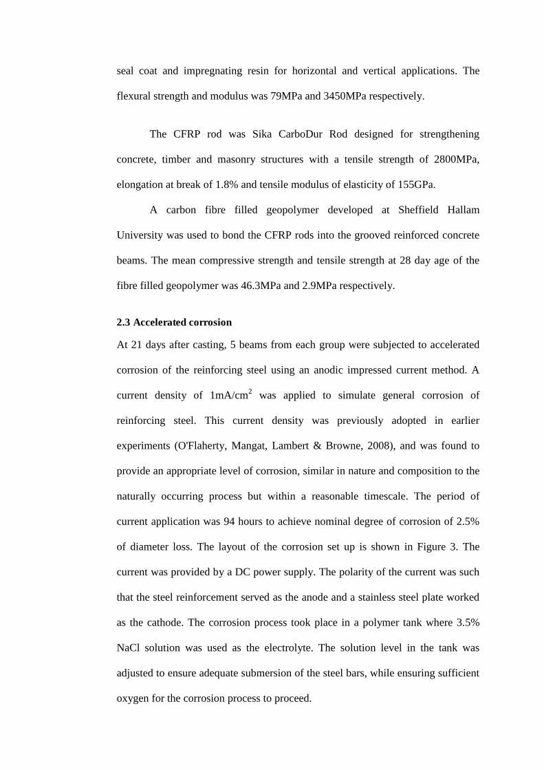
The load- deflection relationships of Group 1 beams are shown in Figure
10. While the ultimate strength of corroded control Beam 1.2 (41.0kN) reduced
compared to the un-corroded control Beam 1.1 (45.5kN), the deflection at failure
of Beam 1.2 (4.54mm) increased compared to Beam 1.1 (3.04mm). This was due
to the influence of steel reinforcement corrosion on the stiffness of beam.
Previous research (O'Flaherty, et al 2010) shows that reinforced concrete beams
show a loss in stiffness with increasing corrosion of the main steel reinforcement
and as the result the stiffness of corroded Beam 1.2 reduced.
The mean ultimate strength of the CFRP rod strengthened beams (1.3 and
1.4) was approximately 23% greater than the ultimate strength of un-strengthened

Beam 1.2 (Table 3). Beams 1.3 and 1.4 both failed due to the debonding of the
CFRP rod (Figure 11). The average ultimate deflection of Beams 1.3 and 1.4
(2.45mm) was reduced by 46% compared with the ultimate deflection of Beam
1.2 (4.54mm) (Table 3). This was attributed to the CFRP rod application to Beams
1.3 and 1.4 leading to an increase in their stiffness compared to Beam 1.2.
Beams 1.5 and 1.6 used the CFRP rod for the dual function of
strengthening and ICCP anode. Comparing the results with the un-strengthened
Beam 1.2, the mean ultimate strength of the beams with the dual function CFRP
rod (Beams 1.5 and 1.6) increased by 6.7%. Again, Beams 1.5 and 1.6 both failed
due to debonding of the CFRP rod anode. The mean ultimate deflection of Beams
1.5 and 1.6 (2.05mm) was approximately 55% less than the ultimate deflection of
Beam 1.2 (4.54mm) (see Table 3). Again, this was attributed to the CFRP rod
application to Beams 1.5 and 1.6 leading to an increase in their stiffness compared
to Beam 1.2.
The mean ultimate strength of Beams 1.5 and 1.6 (43.75kN) in which
CFRP rods were used as ICCP anodes was reduced by about 13%, compared with
the mean ultimate strength of Beams 1.3 and 1.4 (50.45kN) in which CFRP rods
were used for strengthening only (Table 3). This is considered likely to be due to
the application of ICCP adversely affecting the bonding at the CFRP rod
/geopolymer interface or geopolymer/concrete interface. The average ultimate
deflection of Beams 1.5 and 1.6 (2.05mm) was 16% less than the average ultimate
deflection of Beams 1.3 and 1.4 (2.45mm) (see Table 3).
3.2.1 Group 2
The load-deflection relationships of Group 2 are plotted in Figure 12.
While the ultimate strength of corroded control Beam 2.2 (46.9kN) reduced

compared to the un-corroded control Beam 1.1 (49.8kN), the deflection at failure
of Beam 2.2 (8.68mm) increased compared to Beam 1.1 (5.18mm). Similar to
Group 1, this was due to the influence of steel reinforcement corrosion on the
stiffness of beam as stated previously.
The mean ultimate strength of the CFRP rod strengthened beams without
CP (2.3 and 2.4) is 40.3% higher than the equivalent value for the un-strengthened
Beam 2.2. The mean ultimate strength of the dual function beams (CFRP rod
strengthening and CP) (Beams 2.5 and 2.6) is 43.81% higher than Beam 2.2 (see
Table 3). The ultimate strength of the dual function beams is marginally higher
than that of beams with strengthening only. In Group 2 beams, the effect of the
ICCP current on the bond strength at the CFRP rod and repair material interface is
very small when utilising the combination of geopolymer and epoxy.
The failure modes of four strengthened beams were recorded and shown in
Figures 13a to 13d. Flexural failure of Beam 2.3 (Figure 13a) started by the
yielding of steel reinforcement followed by the rupture of second layer repair
material (epoxy) and debonding at the CFRP rod/geopolymer interface. Post-
bending investigation was conducted at the flexural failure section. There was no
debonding at the geopolymer/concrete interface or geopolymer/epoxy interface.
The failure mode of Beam 2.4 (Figure 13b) was similar to Beam 2.3; however, it
was observed that the CFRP rod had a crack across the cross-section. The flexural
failure of Beam 2.5 (Figure 13c) started by the yielding of the reinforcing steel,
followed by the rupture of the epoxy layer. There was debonding at the CFRP
rod/geopolymer interface, however, there was no debonding at the
geopolymer/epoxy interface. Further examination revealed that there was minor
debonding at the geopolymer/concrete substrate interface, due to inadequate cover
to the CFRP rod provided by the geopolymer layer.

The failure mode of Beam 2.6 (Figure 13d) was more complicated. After
yielding of the steel bars, the epoxy layer was ruptured following the formation of
longitudinal cracks in the CFRP rod. Post-bending test investigation revealed that
there was no debonding at the geopolymer/concrete or geopolymer/epoxy
interfaces, however there was debonding at the CFRP rod/geopolymer interface.
The CFRP rod had slipped, which is attributed to a loss of bond at the CFRP rod/
geopolymer interface.
From the detailed examination of the four CFRP rod strengthened beams,
debonding was only observed at the CFRP rod/geopolymer interface. In
comparison with the NSM technique using geopolymer only as the repair material
in Group 1, there is an improvement in the bonding between the CFRP rod and
repair materials, and therefore the capacity of strengthening is increased
significantly.
3.3 Improving bonding at NSM CFRP rod and repair materials using a combination of geopolymer and epoxy
Table 3 shows the ultimate strength of the dual function CFRP rod beams where
NSM CFRP rod was bonded using geopolymer only (Group 1), compared with
NSM CFRP rod bonded using a combination of geopolymer and epoxy (Group 2).
The increase in ultimate load of the repaired beams, compared with corresponding
corroded control beam has been used to assess the effectiveness of the
combination of materials in bonding the CFRP rod. With respect to CFRP rod
strengthening only (without ICCP), the ultimate load of the beams with
geopolymer only increases by 23.05 % compared with the corroded control beam
while the value is 40.3% for the beam strengthened with a combination of
geopolymer and epoxy. In terms of the dual function CFRP rod (with ICCP), the
ultimate load of the beams with geopolymer only increases 6.7% compared to the

corroded control beam while it is 43.85% for beams strengthened with a
combination of materials. The dual function beams of Group 2 (Beams 2.5 and
2.6) presented a better performance than beams of Group 1 (Beams1.5 and 1.6).
The epoxy layer of Group beams 2 is principally to maintain the interaction with
geopolymer and prevent the geopolymer from pulling away. In addition, the
tensile strength of the epoxy is much higher than that of the geopolymer.
4. Conclusion
The main conclusions from the laboratory results reported in this paper are as
follows:
NSM CFRP rod was successfully used as an impressed current cathodic
protection (ICCP) anode for corroded RC beams. It also increases the
ultimate strength of the damaged beams. NSM CFRP rod increases the
stiffness of beams and reduces their ultimate deflection.
The combination of geopolymer and epoxy greatly improves the bonding
of the NSM CFRP rod anode while delivering the ICCP current. The
geopolymer works as a secondary anode and provides additional capacity
for passing the ICCP current to polarize the reinforcing steel, while the
epoxy helps reduce the debonding of the CFRP rod anode, enhancing the
full strength of strengthened beams.
NSM CFRP rod with geopolymer only can operate at >64mA/m2 of steel
area without any signs of damage or mechanical bonding problems. NSM
CFRP rod anodes fixed into grooves in the concrete by a combination of
geopolymer and epoxy can be operated at a very high current density of
approximately 280mA/m2. This high current does not appear to
significantly affect the bonding of the CFRP rod. Although the

strengthening function of CFRP rod anode is not fully utilised, the strength
of the repaired beams still increases significantly by more than 40%
compared with the corroded control beams.
The applied current density is selected on the basis of the distribution to
the protected steel. There is presently no parameter to calculate the
minimum and maximum value of the applied current density for this
system based on theory.
In comparison with traditional CP for reinforced concrete, the CFRP rod
anode appears to be capable of operating at much higher current densities.
By combining the function of strengthening and CP within a single
component, the system is significantly simpler and has the potential to
also deliver cost savings in addition to easier maintenance.
Additional work should focus on the further reduction and ultimate
elimination of the debonding at the CFRP rod anode and geopolymer
interface. In part, this may be achieved by developing the bonding
properties of the geopolymer through further research.
The above mentioned conclusions apply within the limit of the parameters
covered by the test data in the paper. Further research should be conducted prior
to site application.

References
British Standard Institution (2004). Eurocode 2: Design of concrete structures- Part 1-1: General rules and rules for buildings. BS EN 1992-1-1.
Lambert P (2002). Reinforced concrete- history, properties and durability. Technical Note1, Corrosion Prevention Association.
Rodriguez J, Ortega LM, Casal J (1994). Corrosion of reinforcing bars and service life of reinforce concrete structures: corrosion and bond deterioration. International conference on concrete across borders, Odense, Denmark, 315-326.
McLeish A (1987). Structural assessment, Manual for life cycle aspects of concrete in buildings and structures. Taywood Engineering Limited, UK, B4.1-B4.22
Ahmad S (2003). Reinforcement corrosion in concrete structures, its monitoring and service life prediction- a review. Cement & Concrete composites, 25, 459-471.
Asplund, S (1949). Strengthening bridge slabs with grouted reinforcement. ACI Structural Journal, 20(6), 397-406.
El-Hacha R, Rizkalla S (2004). Near surface mounted fibre reinforced polymer reinforcements for flexural strengthening of concrete structures. ACI Structural Journal 101(5), 717-716.
De Lorenzis L, Teng J.G (2007). Near-surface mounted FRP reinforcement: an emerging technique for strengthening structures. Composites, Part B: Engineering, 38, 119–143.
Lambert P (1995). Cathodic protection of reinforced concrete. Anti-corrosion methods and Materials 42(4), 4- 5
Haldemann CH, Schreyer A (1998). Ten years of cathodic protection in concrete in Switzerland. Corrosion of reinforcement in concrete: Monitoring, prevention and rehabilitation papers from Eurocorr’97, European Federation of Corrosion Publication No.25. London: Inst. of Materials.
US Federal Highway Administration (1982). Memorandum on FHWA Position on Cathodic protection Systems.
Pedeferri P (1996). Cathodic protection and cathodic prevention. Construction and Building Materials 10(5),391-402.
The Concrete Society (2012). Cathodic protection of steel in concrete. Technical Report No 73.

Nguyen CV, Lambert P, Mangat P, O’Flaherty F, Jones G (2012). The performance of carbon fibre composite as ICCP anode for reinforced concrete structures. ISRN Corrosion Journal. doi: 10.5402/2012/814923.
American Concrete Institute (2008). Guide for the design and construction of externally bonded FRP systems for strengthening concrete structures. ACI 440.2R-08: 80. Farmington Hills (MI).
O'Flaherty FJ, Mangat PS, Lambert P, Browne EH (2008). Effect of under reinforcement on the flexural strength of corroded beams. Materials and Structures 41, 311-321.
O'Flaherty FJ. Mangat PS, Lambert P, Browne EH (2010). Influence of steel reinforcement corrosion on the stiffness of simply supported concrete beams, Bridge Maintenance, Safety, Management and Life-Cycle Optimization – Frangopol, Sause & Kusko (eds), Taylor & Francis Group, London, ISBN 978-0-415-87786-2, 3436-3441.

Table 1. Details of test programme
Group Beam
Pre-degree of Corrosion (%)
Repair method Comments
CFRP strengthening ICCP application
1
1.1 0 None None Un-corroded control
1.2 2.5 None None Corroded control
1.3 2.5 CFRP rod + Geopolymer
None Strengthening only
1.4 2.5 CFRP rod + Geopolymer
None Strengthening only
1.5 2.5 CFRP rod + Geopolymer
ICCP Dual function
1.6 2.5 CFRP rod + Geopolymer
ICCP Dual function
2
2.1 0 None None Un-corroded control
2.2 2.5 None None Corroded control
2.3 2.5 CFRP rod + (Geopolymer + Epoxy)
None Strengthening only
2.4 2.5 CFRP rod + (Geopolymer + Epoxy)
None Strengthening only
2.5 2.5 CFRP rod + (Geopolymer + Epoxy)
ICCP Dual function
2.6 2.5 CFRP rod + (Geopolymer + Epoxy)
ICCP Dual function
Table 2. Potential decays of steels in the three periods
Beam Time At Potential (Ref electrode: Ag/AgCl/0.5M KCl) Instant off After 4 hours Decays
(hours) mV mV mV
1.5 138 -473 -209 264 330 -454 -175 279 1026 -433 -186 247
1.6 138 -423 -196 227 330 -407 -164 243 1026 -390 -178 212
2.5 520 -374 -235 139 1624 -340 -198 142 2103 -334 -198 136
2.6 520 -265 -118 147 1624 -366 -146 220 2103 -360 -111 249

Table 3. Ultimate load capacity and deflection of beams
Group Beam
Age at test
Actual degree of corrosion
Failure load
Deflection Mean failure load
Mean Deflection
Increase in strength, compared to corroded control
(days) (%) (kN) (mm) (kN) (mm) (%) 1 1.1 218 0 45.5 3.04 45.50 3.04 -
1.2 206 2.04 41.0 4.54 41.00 4.54 - 1.3 233 2.41 49.5 2.30
50.45 2.45 23.05 1.4 242 2.56 51.4 2.61 1.5 236 2.24 42.7 2.08
43.75 2.05 6.70 1.6 245 2.27 44.8 2.02
2 2.1 216 0 49.8 5.18 49.80 5.18 - 2.2 216 2.50 46.9 8.68 46.90 8.68 - 2.3 215 2.53 72.1 5.00
65.80 5.77 40.30 2.4 215 2.44 59.5 6.54 2.5 214 2.67 62.6 4.78
67.45 5.70 43.82 2.6 214 2.76 72.3 6.62

Figure 1. Detailed dimensions of beam specimens
Figure 2. Four point bending test of beams and detailed steel collars
120
900
20
100
150
20
15
20
CFRP Rod 10
Geopolymer
210
Enlarged view of groove
Enlarged view of groove
b) Cross-section of series 2 beams (Geopolymer+ Epoxy)
Epoxy
10
20
20
a) Cross-section of series 1 beams (Geopolymer only)150
100
20
210
Geopolymer
CFRP Rod 10
Steel collars
Mild steel plate 210x 200x10 (mm)
Mild steel plate 270x 150x10 (mm)
LVDT

Figure 3. Accelerated corrosion of reinforcing steel by means of an anodic
impressive current technique
Figure 4. Bonding CFRP rods to grooved beams by geopolymer- Group1
Geopolymer
CFRP rods
Stainless steel plates (External cathodes)
Reinforcing steels (Anodes)
DC power supply

Figure 5. (a). Bonding CFRP rods to pre-grooved beams by geopolymer (first layer of repair material) (b). Overlay of epoxy as the second layer of repair
Figure 6. Schematic ICCP application to corroded reinforced concrete beams
DC powersupply
+-
Reinforcingsteel cathodeConcrete
electrolyte
CFRP rod anode
a) b)
CFRP rods
Geopolymer
Epoxy overlay

Figure 7. Potential (vs Ag/AgCl/0.5M KCl) of steels during operation of ICCP - Beams 1.5 and 1.6 (constant current density of 64.2mA/m2 of steel area)
Figure 8. ICCP applied current densities (mA/m2 of steel surface area)- Beams 2.5 and
2.6
Figure 9. Potential (vs Ag/AgCl/0.5M KCl) of steel bars during ICCP application-
Beams 2.5 and 2.6
-1200
-1000
-800
-600
-400
-200
0
0 200 400 600 800 1000 1200
Po
tent
ial (
mV
)
Time (hours)
1.5
1.6
0
50
100
150
200
250
300
350
0 500 1000 1500 2000 2500
Cu
rre
nt
de
nsi
ty (
mA
/m2)
Time (hours) 2.5 2.6
-800
-700
-600
-500
-400
-300
-200
-100
0
0 500 1000 1500 2000 2500
Po
ten
tia
l (m
V)
Time (hours)
2.5 2.6
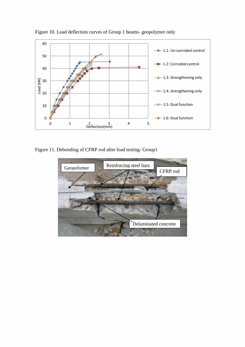
Figure 10. Load deflection curves of Group 1 beams- geopolymer only
Figure 11. Debonding of CFRP rod after load testing- Group1
0
10
20
30
40
50
60
0 1 2 3 4 5
Loa
d (
kN
)
Deflection(mm)
1.1: Un-corroded control
1.2: Corroded control
1.3: Strengthening only
1.4: strengthening only
1.5: Dual function
1.6: Dual function
CFRP rod Reinforcing steel bars
Delaminated concrete
Geopolymer

Figure 12. Load-deflection curves of Group 2 beams- combination of geopolymer and epoxy
0
10
20
30
40
50
60
70
80
0 5 10 15 20
Loa
d (
kN
)
Deflection
2.1: Un-corroded control
2.2: Corroded control
2.3: Strengthening only
2.4: Strengthening only
2.5: Dual function
2.6: Dual function

Figure 13. Failed beams
a) Failure of strengthening only beam 2.3 b) Failure of strengthening only beam 2.4 c) Failure of dual function beam 2.5 d) Failure of dual function beam 2.6
a) b)
c) d)