Embed Size (px)
Citation preview
replace
Neptune
Owners Manual
Training with the Neptune Rower 1. As with any piece of fitness equipment, consult a physician before beginning your Neptune Rower exercise program.
2. Follow instructions provided in this manual for correct foot position and basic rowing techniques Caution
1. The Neptune Rower can stand vertically for storage. When doing so, please choose a secure location, such as the corner of a room. 2. Keep hands away from moving parts, as indicated by the warning sticker on the mainframe of your machine.
Contents 1. Contents of Neptune Rower Pack. 2. Assembly Instructions. 3. Tank filling and water treatment. 4. Changing/Replacing tank water 5. The Neptune Rower Computer. 6. Replacing Rower belt. 7. Replacing Bungee cord. 8. Maintenance and Troubleshooting. 9. Parts list. 10. Warranty.
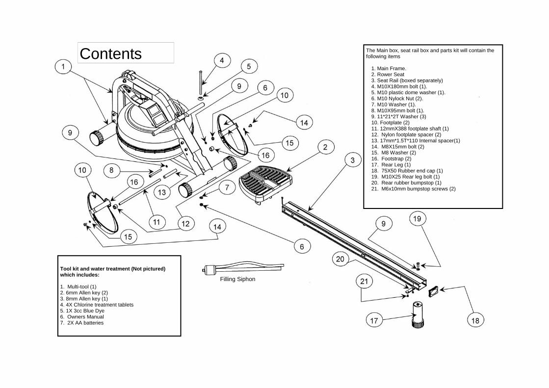
The Main box, seat rail box and parts kit will contain the following items
1. Main Frame. 2. Rower Seat 3. Seat Rail (boxed separately) 4. M10X180mm bolt (1). 5. M10 plastic dome washer (1). 6. M10 Nylock Nut (2). 7. M10 Washer (1). 8. M10X95mm bolt (1). 9. 11*21*2T Washer (3) 10. Footplate (2) 11. 12mmX388 footplate shaft (1) 12. Nylon footplate spacer (2) 13. 17mm*1.5T*110 Internal spacer(1) 14. M8X15mm bolt (2) 15. M8 Washer (2) 16. Footstrap (2) 17. Rear Leg (1) 18. 75X50 Rubber end cap (1) 19. M10X25 Rear leg bolt (1) 20. Rear rubber bumpstop (1) 21. M6x10mm bumpstop screws (2)
Contents
Filling Siphon
Tool kit and water treatment (Not pictured) which includes: 1. Multi-tool (1) 2. 6mm Allen key (2) 3. 8mm Allen key (1) 4. 4X Chlorine treatment tablets 5. 1X 3cc Blue Dye 6. Owners Manual 7. 2X AA batteries
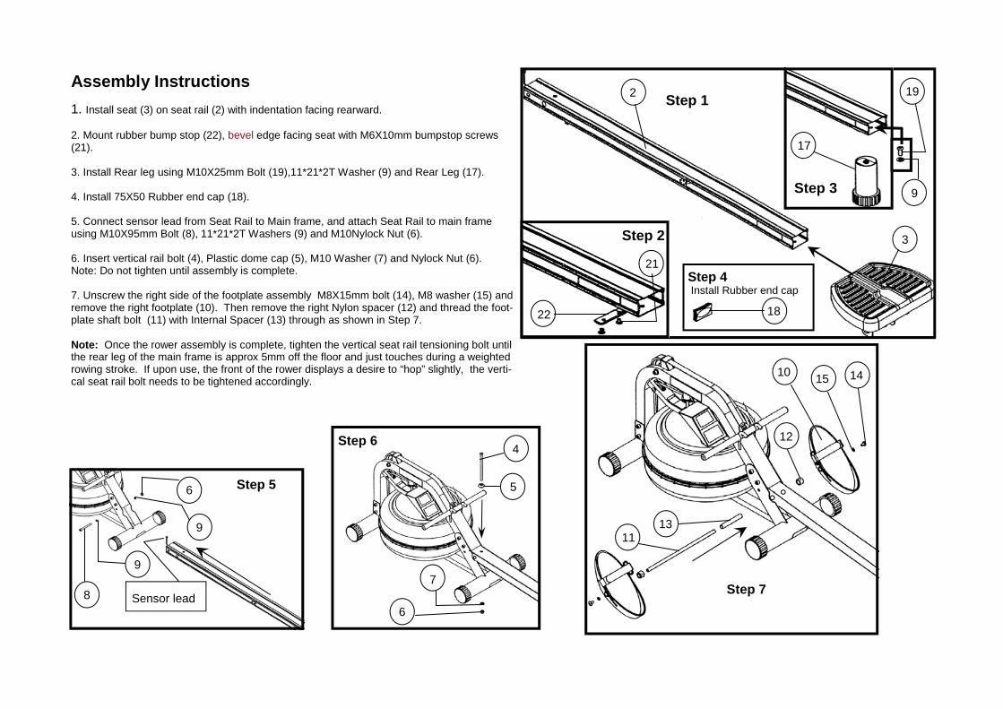
Assembly Instructions 1. Install seat (3) on seat rail (2) with indentation facing rearward. 2. Mount rubber bump stop (22), bevel edge facing seat with M6X10mm bumpstop screws (21). 3. Install Rear leg using M10X25mm Bolt (19),11*21*2T Washer (9) and Rear Leg (17). 4. Install 75X50 Rubber end cap (18). 5. Connect sensor lead from Seat Rail to Main frame, and attach Seat Rail to main frame using M10X95mm Bolt (8), 11*21*2T Washers (9) and M10Nylock Nut (6). 6. Insert vertical rail bolt (4), Plastic dome cap (5), M10 Washer (7) and Nylock Nut (6). Note: Do not tighten until assembly is complete. 7. Unscrew the right side of the footplate assembly M8X15mm bolt (14), M8 washer (15) and remove the right footplate (10). Then remove the right Nylon spacer (12) and thread the foot-plate shaft bolt (11) with Internal Spacer (13) through as shown in Step 7. Note: Once the rower assembly is complete, tighten the vertical seat rail tensioning bolt until the rear leg of the main frame is approx 5mm off the floor and just touches during a weighted rowing stroke. If upon use, the front of the rower displays a desire to “hop” slightly, the verti-cal seat rail bolt needs to be tightened accordingly.
Step 1
Step 2
Step 3
Step 4 Install Rubber end cap
Step 5
Step 6
Step 7
3
2
21
22
19
17
9
18
6
9
9
8 Sensor lead 6
7
5
4
10 14 15
12
13 11
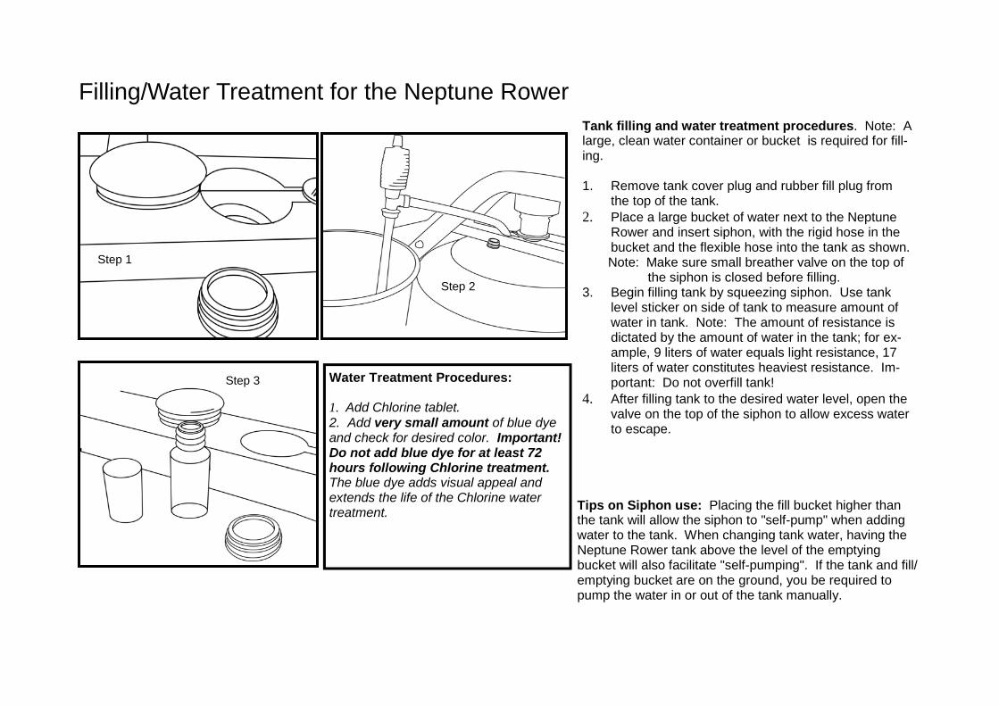
Tank filling and water treatment procedures. Note: A large, clean water container or bucket is required for fill-ing. 1. Remove tank cover plug and rubber fill plug from
the top of the tank. 2. Place a large bucket of water next to the Neptune
Rower and insert siphon, with the rigid hose in the bucket and the flexible hose into the tank as shown.
Note: Make sure small breather valve on the top of the siphon is closed before filling. 3. Begin filling tank by squeezing siphon. Use tank
level sticker on side of tank to measure amount of water in tank. Note: The amount of resistance is dictated by the amount of water in the tank; for ex-ample, 9 liters of water equals light resistance, 17 liters of water constitutes heaviest resistance. Im-portant: Do not overfill tank!
4. After filling tank to the desired water level, open the valve on the top of the siphon to allow excess water to escape.
Tips on Siphon use: Placing the fill bucket higher than the tank will allow the siphon to "self-pump" when adding water to the tank. When changing tank water, having the Neptune Rower tank above the level of the emptying bucket will also facilitate "self-pumping". If the tank and fill/emptying bucket are on the ground, you be required to pump the water in or out of the tank manually.
Filling/Water Treatment for the Neptune Rower
Water Treatment Procedures: 1. Add Chlorine tablet. 2. Add very small amount of blue dye and check for desired color. Important! Do not add blue dye for at least 72 hours following Chlorine treatment. The blue dye adds visual appeal and extends the life of the Chlorine water treatment.
Step 1
Step 2
Step 3
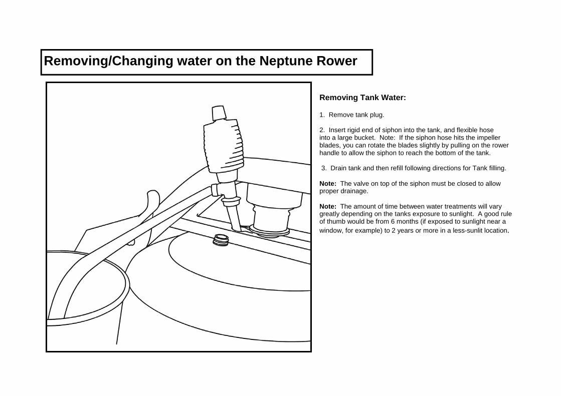
Removing/Changing water on the Neptune Rower
Removing Tank Water: 1. Remove tank plug. 2. Insert rigid end of siphon into the tank, and flexible hose into a large bucket. Note: If the siphon hose hits the impeller blades, you can rotate the blades slightly by pulling on the rower handle to allow the siphon to reach the bottom of the tank. 3. Drain tank and then refill following directions for Tank filling. Note: The valve on top of the siphon must be closed to allow proper drainage. Note: The amount of time between water treatments will vary greatly depending on the tanks exposure to sunlight. A good rule of thumb would be from 6 months (if exposed to sunlight near a window, for example) to 2 years or more in a less-sunlit location.
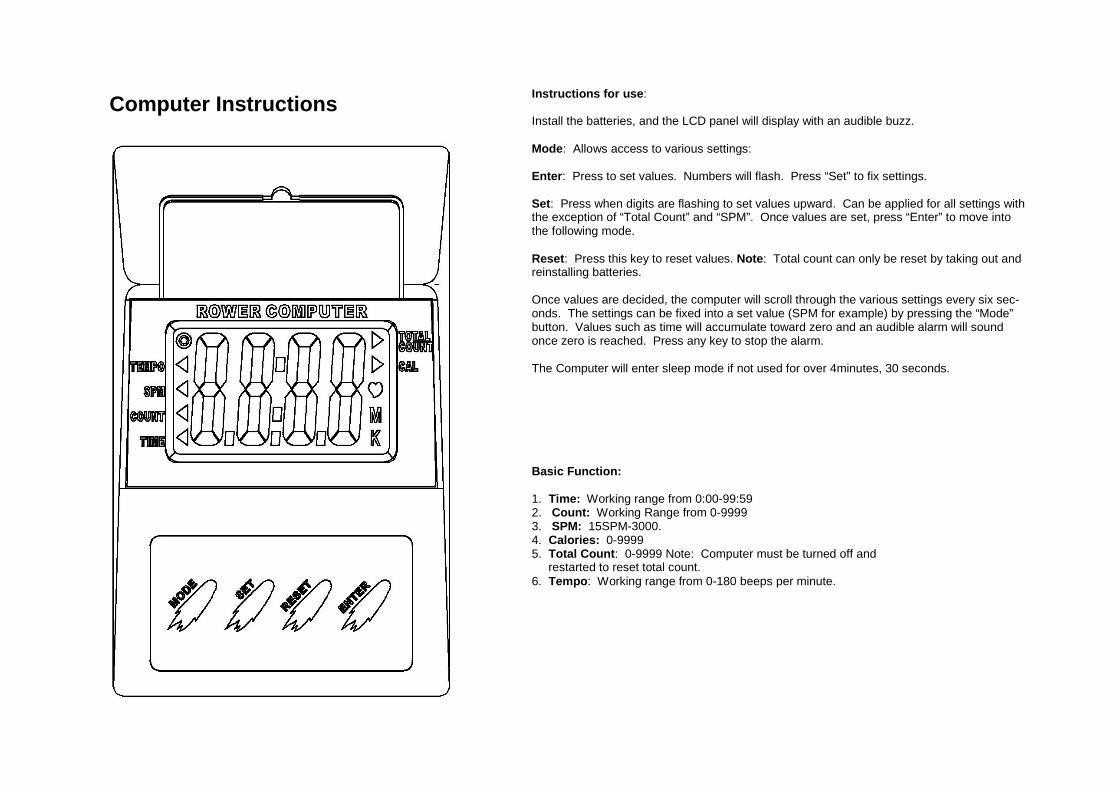
Computer Instructions
Basic Function: 1. Time: Working range from 0:00-99:59 2. Count: Working Range from 0-9999 3. SPM: 15SPM-3000. 4. Calories: 0-9999 5. Total Count: 0-9999 Note: Computer must be turned off and restarted to reset total count. 6. Tempo: Working range from 0-180 beeps per minute.
Instructions for use: Install the batteries, and the LCD panel will display with an audible buzz. Mode: Allows access to various settings: Enter: Press to set values. Numbers will flash. Press “Set” to fix settings. Set: Press when digits are flashing to set values upward. Can be applied for all settings with the exception of “Total Count” and “SPM”. Once values are set, press “Enter” to move into the following mode. Reset: Press this key to reset values. Note: Total count can only be reset by taking out and reinstalling batteries. Once values are decided, the computer will scroll through the various settings every six sec-onds. The settings can be fixed into a set value (SPM for example) by pressing the “Mode” button. Values such as time will accumulate toward zero and an audible alarm will sound once zero is reached. Press any key to stop the alarm. The Computer will enter sleep mode if not used for over 4minutes, 30 seconds.
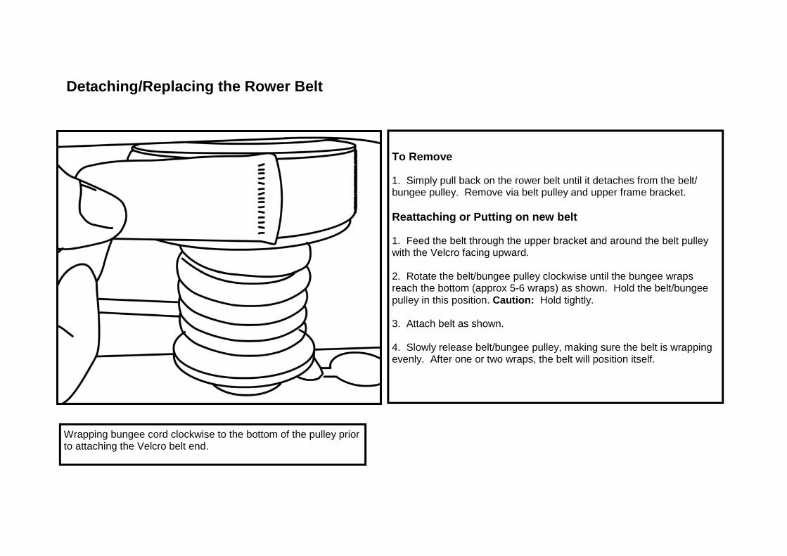
Wrapping bungee cord clockwise to the bottom of the pulley prior to attaching the Velcro belt end.
To Remove 1. Simply pull back on the rower belt until it detaches from the belt/bungee pulley. Remove via belt pulley and upper frame bracket. Reattaching or Putting on new belt 1. Feed the belt through the upper bracket and around the belt pulley with the Velcro facing upward. 2. Rotate the belt/bungee pulley clockwise until the bungee wraps reach the bottom (approx 5-6 wraps) as shown. Hold the belt/bungee pulley in this position. Caution: Hold tightly. 3. Attach belt as shown. 4. Slowly release belt/bungee pulley, making sure the belt is wrapping evenly. After one or two wraps, the belt will position itself.
Detaching/Replacing the Rower Belt
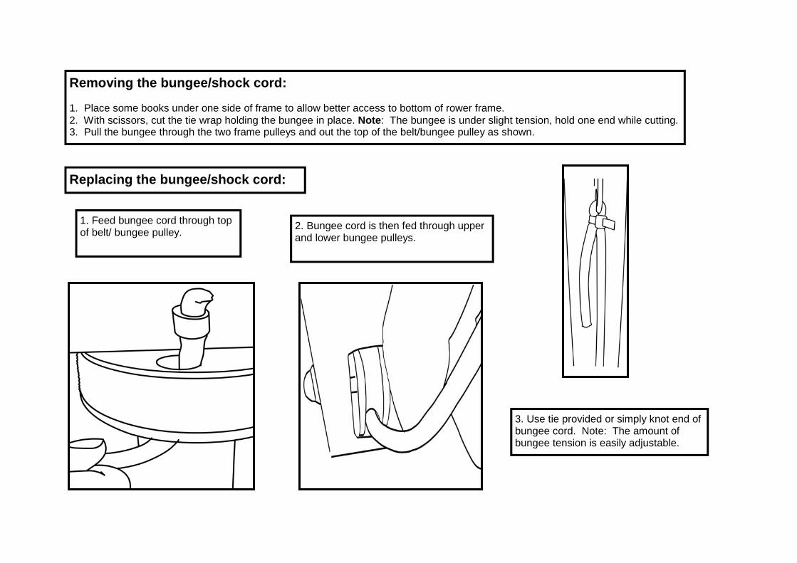
Removing the bungee/shock cord: 1. Place some books under one side of frame to allow better access to bottom of rower frame. 2. With scissors, cut the tie wrap holding the bungee in place. Note: The bungee is under slight tension, hold one end while cutting. 3. Pull the bungee through the two frame pulleys and out the top of the belt/bungee pulley as shown.
Replacing the bungee/shock cord:
1. Feed bungee cord through top of belt/ bungee pulley. 2. Bungee cord is then fed through upper
and lower bungee pulleys.
3. Use tie provided or simply knot end of bungee cord. Note: The amount of bungee tension is easily adjustable.
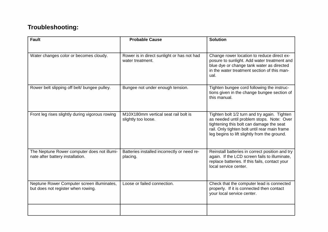
Troubleshooting:
Fault Probable Cause Solution
Water changes color or becomes cloudy.
Rower is in direct sunlight or has not had water treatment.
Change rower location to reduce direct ex-posure to sunlight. Add water treatment and blue dye or change tank water as directed in the water treatment section of this man-ual.
Rower belt slipping off belt/ bungee pulley. Bungee not under enough tension.
Tighten bungee cord following the instruc-tions given in the change bungee section of this manual.
Front leg rises slightly during vigorous rowing
M10X180mm vertical seat rail bolt is slightly too loose.
Tighten bolt 1/2 turn and try again. Tighten as needed until problem stops. Note: Over tightening this bolt can damage the seat rail. Only tighten bolt until rear main frame leg begins to lift slightly from the ground.
The Neptune Rower computer does not illumi-nate after battery installation.
Batteries installed incorrectly or need re-placing.
Reinstall batteries in correct position and try again. If the LCD screen fails to illuminate, replace batteries. If this fails, contact your local service center.
Neptune Rower Computer screen illuminates, but does not register when rowing.
Loose or failed connection.
Check that the computer lead is connected properly. If it is connected then contact your local service center.
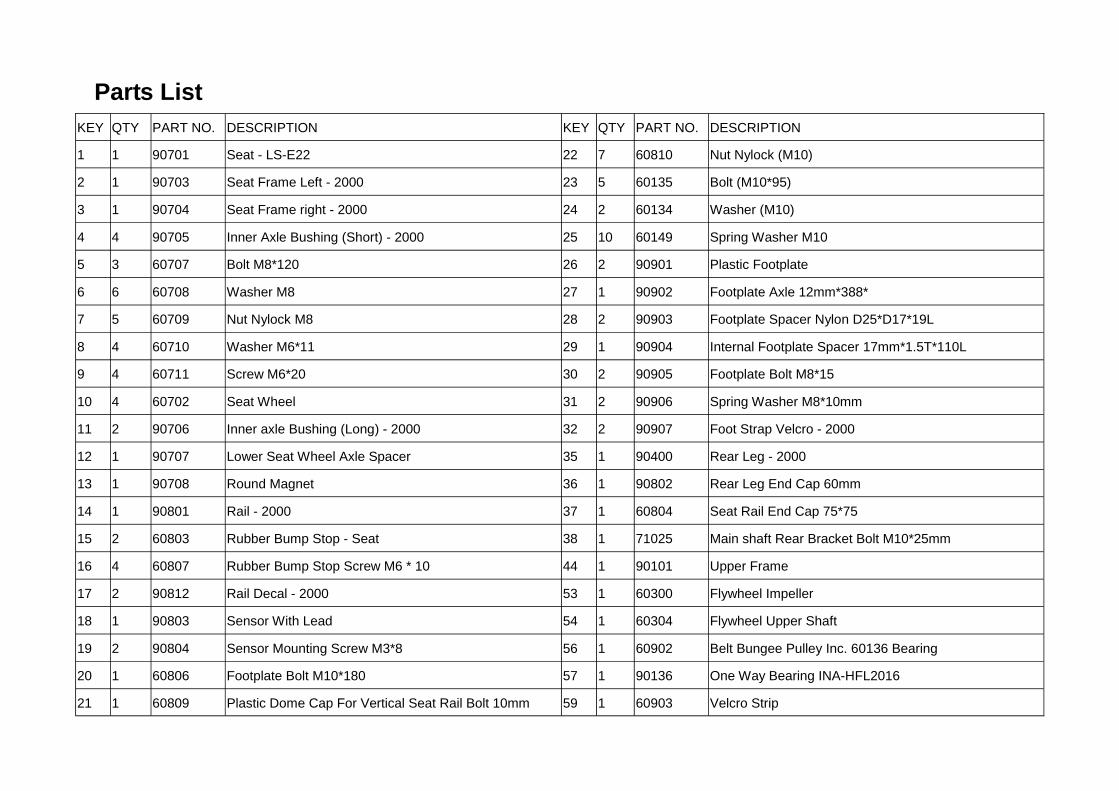
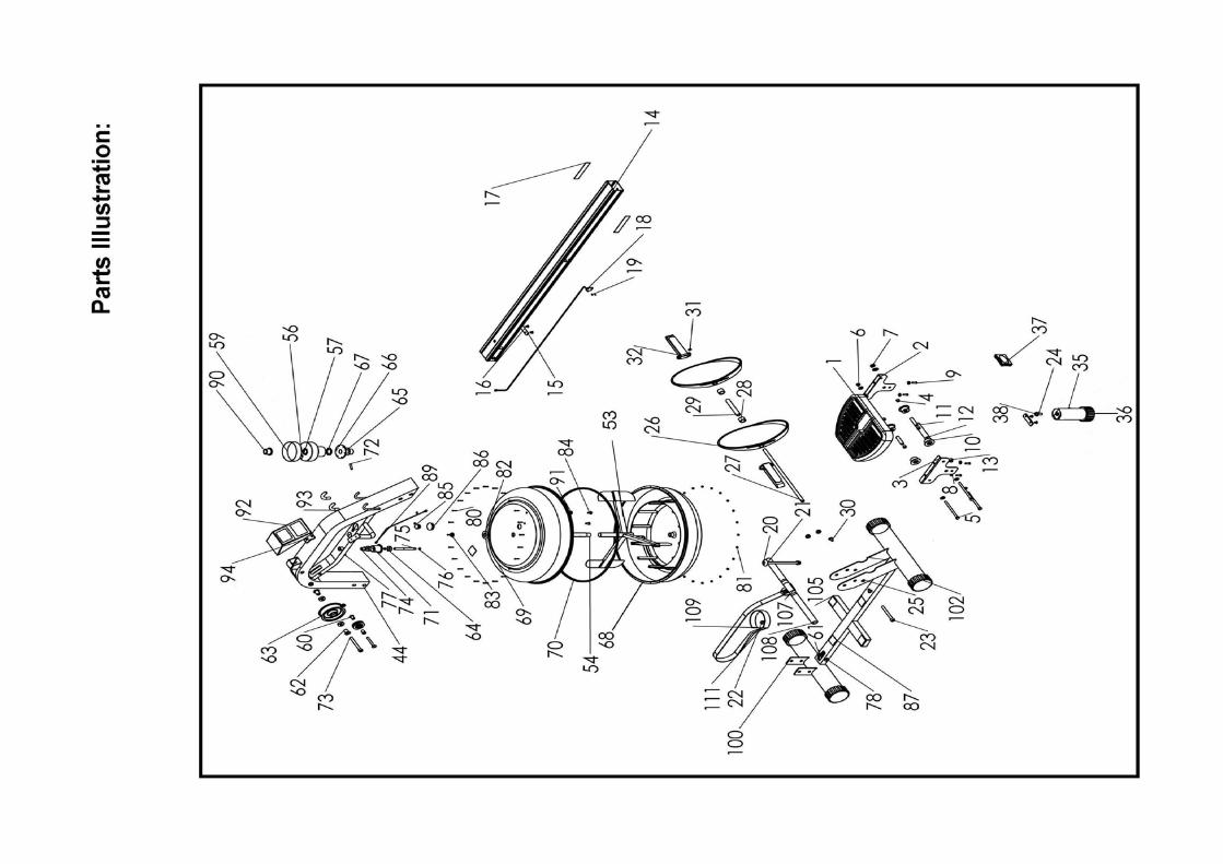
Parts List KEY QTY PART NO. DESCRIPTION KEY QTY PART NO. DESCRIPTION
1 1 90701 Seat - LS-E22 22 7 60810 Nut Nylock (M10)
2 1 90703 Seat Frame Left - 2000 23 5 60135 Bolt (M10*95)
3 1 90704 Seat Frame right - 2000 24 2 60134 Washer (M10)
4 4 90705 Inner Axle Bushing (Short) - 2000 25 10 60149 Spring Washer M10
5 3 60707 Bolt M8*120 26 2 90901 Plastic Footplate
6 6 60708 Washer M8 27 1 90902 Footplate Axle 12mm*388*
7 5 60709 Nut Nylock M8 28 2 90903 Footplate Spacer Nylon D25*D17*19L
8 4 60710 Washer M6*11 29 1 90904 Internal Footplate Spacer 17mm*1.5T*110L
9 4 60711 Screw M6*20 30 2 90905 Footplate Bolt M8*15
10 4 60702 Seat Wheel 31 2 90906 Spring Washer M8*10mm
11 2 90706 Inner axle Bushing (Long) - 2000 32 2 90907 Foot Strap Velcro - 2000
12 1 90707 Lower Seat Wheel Axle Spacer 35 1 90400 Rear Leg - 2000
13 1 90708 Round Magnet 36 1 90802 Rear Leg End Cap 60mm
14 1 90801 Rail - 2000 37 1 60804 Seat Rail End Cap 75*75
15 2 60803 Rubber Bump Stop - Seat 38 1 71025 Main shaft Rear Bracket Bolt M10*25mm
16 4 60807 Rubber Bump Stop Screw M6 * 10 44 1 90101 Upper Frame
17 2 90812 Rail Decal - 2000 53 1 60300 Flywheel Impeller
18 1 90803 Sensor With Lead 54 1 60304 Flywheel Upper Shaft
19 2 90804 Sensor Mounting Screw M3*8 56 1 60902 Belt Bungee Pulley Inc. 60136 Bearing
20 1 60806 Footplate Bolt M10*180 57 1 90136 One Way Bearing INA-HFL2016
21 1 60809 Plastic Dome Cap For Vertical Seat Rail Bolt 10mm 59 1 60903 Velcro Strip
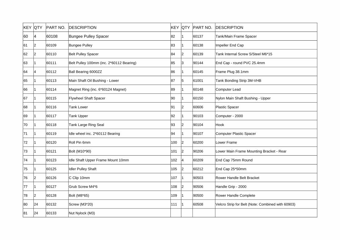
KEY QTY PART NO. DESCRIPTION KEY QTY PART NO. DESCRIPTION
60 4 60108 Bungee Pulley Spacer 82 1 60137 Tank/Main Frame Spacer
61 2 60109 Bungee Pulley 83 1 60138 Impeller End Cap
62 2 60110 Belt Pulley Spacer 84 2 60139 Tank Internal Screw S/Steel M6*15
63 1 60111 Belt Pulley 100mm (inc. 2*60112 Bearing) 85 3 90144 End Cap - round PVC 25.4mm
64 4 60112 Ball Bearing 6000ZZ 86 1 60145 Frame Plug 38.1mm
65 1 60113 Main Shaft Oil Bushing - Lower 87 5 61001 Tank Bonding Strip 3M-VHB
66 1 60114 Magnet Ring (inc. 6*60124 Magnet) 89 1 60148 Computer Lead
67 1 60115 Flywheel Shaft Spacer 90 1 60150 Nylon Main Shaft Bushing - Upper
68 1 60116 Tank Lower 91 2 60606 Plastic Spacer
69 1 60117 Tank Upper 92 1 90103 Computer - 2000
70 1 60118 Tank Large Ring Seal 93 2 90104 Hook
71 1 60119 Idle wheel inc. 2*60112 Bearing 94 1 90107 Computer Plastic Spacer
72 1 60120 Roll Pin 6mm 100 2 60200 Lower Frame
73 1 60121 Bolt (M10*90) 101 2 90206 Lower Main Frame Mounting Bracket - Rear
74 1 60123 Idle Shaft Upper Frame Mount 10mm 102 4 60209 End Cap 75mm Round
75 1 60125 Idler Pulley Shaft 105 2 60212 End Cap 25*50mm
76 2 60126 C Clip 10mm 107 1 90503 Rower Handle Belt Bracket
77 1 60127 Grub Screw M4*6 108 2 90506 Handle Grip - 2000
78 2 60128 Bolt (M8*65) 109 1 90500 Rower Handle Complete
80 24 60132 Screw (M3*20) 111 1 60508 Velcro Strip for Belt (Note: Combined with 60903)
81 24 60133 Nut Nylock (M3)
NEPTUNE ROWER INTERNATIONAL WARRANTY
WAVE FITNESS warrants that the Neptune Rower (model WRN-1), purchased from an authorized agent, is free from defects in mate-rials and workmanship. WAVE FITNESS or its agents will, at their discretion, repair or replace parts that become defective within the warranty period. Metal Frame – 5 Year Limited Warranty WAVE FITNESS will repair or replace the metal Main Frame of the Rower should it fail due to any defect in materials or workmanship within 5 years of the original purchase. Warranty does not apply to frame coating. Polycarbonate Tank & Seals – 2 Year Limited Warranty WAVE FITNESS will repair or replace the polycarbonate tank or seals should they fail due to any defect in materials or workmanship within 2 years of the original purchase. Mechanical Components (of a non-wearing nature) – 2 Year Limited Warranty WAVE FITNESS will repair or replace any mechanical component should it fail due to any defect in materials or workmanship within 2 years of the original purchase. Specific Inclusions
● Aluminum Seat Rail ● Stainless Steel Paddle Assembly
Wave Fitness Limited
All Other Components (of a wearing nature) – 1 Year Limited Warranty WAVE FITNESS will repair or replace any component should it fail due to any defect in materials or workmanship within 1 year of the original purchase. Specific Inclusions ● Bungee recoil cord ● Hand grips & foot straps ● Polyester rowing belt ● Seat ● Seat rollers & bearings ● All rubber components ● Computer & speed sensor (excluding replaceable batteries) ● All pulleys, bushings & bearings General Exclusions ● Damage to the finish of any part of the machine ● Damage due to neglect, abuse or incorrect use of the machine ● Any charges for freight or customs clearance associated with the return or dispatch of parts ● Any damage to or loss of goods during transport of any kind ● Any labor cost associated with a warranty claim General Conditions ● The serial number of the machine must be correctly registered with WAVE FITNESS Limited or one of its appointed distributors ● WAVE FITNESS Limited reserve the right to examine any part where replacement is claimed under warranty ● Warranty period applies only to the original purchaser from the date of purchase and is not transferable ● The product must be returned to your place of purchase in original packaging with transportation, insurance and associated
charges paid for by you and risk of loss or damage assumed by you ● WAVE FITNESS makes no other warranties except as stated here and expressly disclaims all warranties not stated in this war-
ranty. Neither WAVE FITNESS nor its associates shall be responsible for incidental or consequential damages