Embed Size (px)
Citation preview

www.georgin.com
SELECTION GUIDEInterfaces – galvanic insulation
SELECTION GUIDEInterfaces – galvanic insulation

1. Principle of a galvanic insulation and notions of intrinsic safety1. Principle of a galvanic insulation 4
2. Notions of intrinsic safety 7
2. General specifications for galvanic insulation interfaces1. Mechanical properties 12
2. Certifications 12
3. Dimensions 12
3. Selection guide1. Analog inputs - standard 14
2. Analog inputs - HART compatible 16
3. Analog inputs - converter 18
4. Analog inputs - isolator 20
5. Digital inputs - relay outputs 22
6. Digital inputs - transistor outputs 24
7. Digital inputs - output relays with input memory 26
8. Digital inputs - signal isolator 28
9. Analog inputs - converter 30
10. Analog output - isolator 32
11. Impedance transfer table (BXNI*T and BXNI*A) 34
12. Digital outputs - 1 channel power supplies 36
13. Digital outputs - 2-channel power supplies controlled by 24 V DC 38
14. Digital outputs - 2-channel power supplies controlled by contact 40
15. Power curves and IS parameters (BXNE) 42
16. Example of BXNE selection 45
17. Digital inputs - opto-isolator output signal isolator 46
18. Digital outputs - relay output signal isolator 48
19. Temperature inputs - converter 50
20. Potentiometer inputs - resistance - converter 52
21. Universal inputs - threshold relays 54
4. Use of galvanic insulation1. Connection 58
2. Installation 58
3. Fixing and mounting 58
4. Location 58
5. Electrical connection 58
6. Mechanical properties 58
7. Cable routing 59
8. Adjustments and configuration 59
9. Maintenance 59
10. Dismounting 59
5. Table of equivalent references according to type of assembly1. Assembly methods 62
GEORGIN France : Tel : +33 (0)1 46 12 60 00 - Fax : +33 (0)1 47 35 93 98 - [email protected] Belgium : Tel : 02 735 54 75 - Fax : 02 735 16 79 - [email protected]
www.georgin.com
IS interfaces


3www.georgin.com
Tabl
e of
equ
ival
ent
refe
renc
es
acco
rdin
g to
typ
e of
ass
embl
yUs
e of
gal
vani
c in
sula
tion
Sele
ctio
n gu
ide
Gene
ral s
peci
ficat
ions
for
ga
lvan
ic in
sula
tion
inte
rfac
esPr
inci
ple
of a
gal
vani
c in
sula
tion
and
rem
inde
rs c
once
rnin
g I.S
.
IS interfaces
1. Principle of a galvanic insulation and notions of intrinsic safety

4www.georgin.com
Tabl
e of
equ
ival
ent
refe
renc
es
acco
rdin
g to
typ
e of
ass
embl
yUs
e of
gal
vani
c in
sula
tion
Sele
ctio
n gu
ide
Gene
ral s
peci
ficat
ions
for
ga
lvan
ic in
sula
tion
inte
rfac
esPr
inci
ple
of a
gal
vani
c in
sula
tion
and
rem
inde
rs c
once
rnin
g I.S
.IS interfaces
A galvanic insulation barrier is an associated equipment that is generally installed in the safe area.
Its main function in safety terms is to limit the level of energy that may appear in an electric circuit routed through a hazardous area, whatever the connection established upstream of this barrier. A galvanic insulation barrier comprises:
safety transformers opto-isolators intrinsic safety relays resistances fuses Zener diodes
Like any other intrinsic safety equipment, this device enables short circuits between cables or with grounded metal parts without danger.
The interface through a galvanic insulation barrier is different from other interface modes:Cables routed through hazardous areas have no common points with those in safe areas. There is therefore no use in grounding such a barrier.
Figure 1 presents a galvanic insulation barrier (B) that feeds any type of equipment. This barrier is controlled by the programmable logic controller (PLC) (C).Details of the components of an intrinsic safety barrier:
1. Principle of a galvanic insulation
5www.georgin.com
Tabl
e of
equ
ival
ent
refe
renc
es
acco
rdin
g to
typ
e of
ass
embl
yUs
e of
gal
vani
c in
sula
tion
Sele
ctio
n gu
ide
Gene
ral s
peci
ficat
ions
for
ga
lvan
ic in
sula
tion
inte
rfac
esPr
inci
ple
of a
gal
vani
c in
sula
tion
and
rem
inde
rs c
once
rnin
g I.S
.
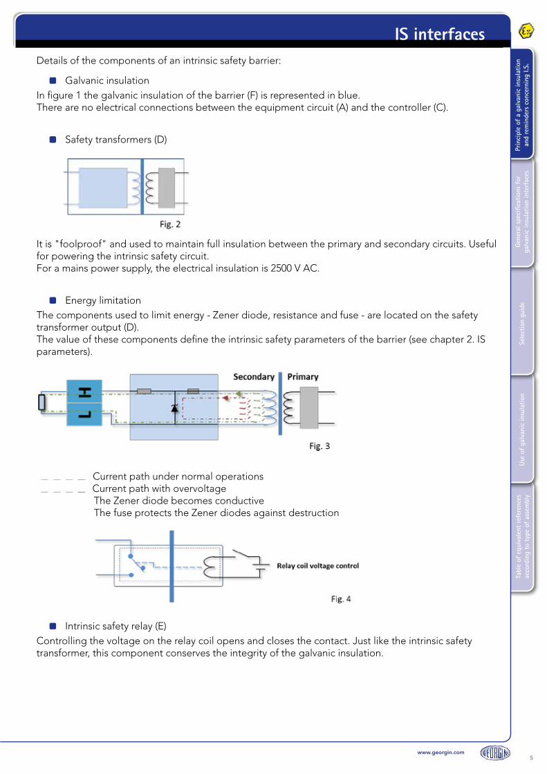
IS interfacesDetails of the components of an intrinsic safety barrier:
Galvanic insulationIn figure 1 the galvanic insulation of the barrier (F) is represented in blue.There are no electrical connections between the equipment circuit (A) and the controller (C).
Safety transformers (D)
It is "foolproof" and used to maintain full insulation between the primary and secondary circuits. Useful for powering the intrinsic safety circuit.For a mains power supply, the electrical insulation is 2500 V AC.
Energy limitationThe components used to limit energy - Zener diode, resistance and fuse - are located on the safety transformer output (D).The value of these components define the intrinsic safety parameters of the barrier (see chapter 2. IS parameters).
Current path under normal operations Current path with overvoltage
The Zener diode becomes conductiveThe fuse protects the Zener diodes against destruction
Intrinsic safety relay (E)Controlling the voltage on the relay coil opens and closes the contact. Just like the intrinsic safety transformer, this component conserves the integrity of the galvanic insulation.

6www.georgin.com
Tabl
e of
equ
ival
ent
refe
renc
es
acco
rdin
g to
typ
e of
ass
embl
yUs
e of
gal
vani
c in
sula
tion
Sele
ctio
n gu
ide
Gene
ral s
peci
ficat
ions
for
ga
lvan
ic in
sula
tion
inte
rfac
esPr
inci
ple
of a
gal
vani
c in
sula
tion
and
rem
inde
rs c
once
rnin
g I.S
.IS interfaces
Opto-isolatorThis component is not represented on figure 1. It is used to transfer information from the intrinsic safety circuit to the conventional part of the circuit while conserving the integrity of the galvanic insulation.The opening of the output transistor (EF) is controlled via a photo-sensitive receiver.When the current passes via (JH), a LED lights up and makes the transistor conductive.
In addition to their insulation and energy limitation function, active galvanic insulation barriers are useful and employed in different applications:
Signal conversion
Analog or digital output repeaters
Threshold relays
Alarm functions
etc.
These functions are described in greater detail in the Selection Guide chapter, page 13.

7www.georgin.com
Tabl
e of
equ
ival
ent
refe
renc
es
acco
rdin
g to
typ
e of
ass
embl
yUs
e of
gal
vani
c in
sula
tion
Sele
ctio
n gu
ide
Gene
ral s
peci
ficat
ions
for
ga
lvan
ic in
sula
tion
inte
rfac
esPr
inci
ple
of a
gal
vani
c in
sula
tion
and
rem
inde
rs c
once
rnin
g I.S
.
IS interfaces
Like any intrinsic safety device connected to a sensor (also an IS device), the whole constitutes what the standard refers to as an "intrinsic safety system", the parameters of which must be compatible in terms of intrinsic safety.
European Directive 1999/92/EC (the ATEX Directive) requires that the compliance of the safety system must be proven.
The definition of a galvanic insulation barrier therefore requires the collection of a certain amount of information concerning its environment, to ensure that the system operates correctly and is reliable.
So to define a suitable barrier, the following information is required:
Full references of the associated equipment and other equipment in the hazardous area:To identify the device in question in the ATEX certificate and the technical data sheet.
Technical data sheet or instruction notice for the interfaces and equipment in the hazardous area: To identify the metrological data of the equipment.
ATEX Certificate for the interfaces and equipment in the hazardous area:To identify the intrinsic safety parameters and the device markings.
An intrinsic safety system generally comprises: Intrinsic safety equipment installed in a hazardous area Associated equipment installed in the safe area Connection cables Accessories (junction boxes, power outlets, switches, etc.)
Associated equipment:It is located in the safe area. In terms of intrinsic safety, it must be considered as an energy source.
This energy source is characterized by three parameters: Voltage: Uo
Current: Io
Power: Po
This signifies that the associated equipment may never supply a voltage greater than Uo, a current greater than Io or power greater than Po to an external medium.
Cabling:For each piece of associated equipment, the limit properties of the external cabling Co and Lo are defined to ensure that the system remains safe:
Co represents the maximum capacitance that can be connected to the associated equipment Lo represents the maximum inductance that can be connected to the associated equipment ∑Ci represents the sum of the capacities of the cable and the intrinsic safety equipment on the loop.
∑Li represents the sum of the inductances of the cable and the intrinsic safety equipment on the loop.
2. Notions of intrinsic safety

8www.georgin.com
Tabl
e of
equ
ival
ent
refe
renc
es
acco
rdin
g to
typ
e of
ass
embl
yUs
e of
gal
vani
c in
sula
tion
Sele
ctio
n gu
ide
Gene
ral s
peci
ficat
ions
for
ga
lvan
ic in
sula
tion
inte
rfac
esPr
inci
ple
of a
gal
vani
c in
sula
tion
and
rem
inde
rs c
once
rnin
g I.S
.IS interfaces
Intrinsic safety equipment:
Located in the hazardous area, it must be considered as a receiver of energy due to the terminals that are connected to the associated equipment.
This energy receiver is characterized by three parameters that define the maximum limits: Ui, Ii, Pi. This means that as long as the characteristics of the energy supplied to it remain below Ui, Ii and Pi, this intrinsic safety equipment will remain safe.
Each piece of intrinsic safety equipment is also characterized by the values Ci and Li which are the values of the capacity and internal inductance of the intrinsic safety equipment.
The intrinsic safety parameters in a simple system (Receiver, barrier, equipment in hazardous area) are validated by comparing the intrinsic safety parameters of the barrier and the equipment in the area using the following rule:
Verification of voltage:Uo (barrier) ≤ Ui (equipment in hazardous area)
Verification of current:Io (barrier) ≤ Ii (equipment in hazardous area)
Verification of power:Po (barrier) ≤ Pi (equipment in hazardous area)
Verification of capacitance:Cc (cable) + Ci (equipment in hazardous area) ≤ Co (barrier)
Verification of inductance:Lc + Li (equipment in hazardous area) ≤ Lo (barrier)
9www.georgin.com
Tabl
e of
equ
ival
ent
refe
renc
es
acco
rdin
g to
typ
e of
ass
embl
yUs
e of
gal
vani
c in
sula
tion
Sele
ctio
n gu
ide
Gene
ral s
peci
ficat
ions
for
ga
lvan
ic in
sula
tion
inte
rfac
esPr
inci
ple
of a
gal
vani
c in
sula
tion
and
rem
inde
rs c
once
rnin
g I.S
.
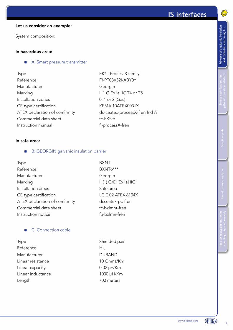
IS interfacesLet us consider an example:
System composition:
In hazardous area:
A: Smart pressure transmitter
Type FK* - ProcessX family
Reference FKPT03V52KABY0Y
Manufacturer Georgin
Marking II 1 G Ex ia IIC T4 or T5
Installation zones 0, 1 or 2 (Gas)
CE type certification KEMA 10ATEX0031X
ATEX declaration of confirmity dc-ceatex-processX-fren Ind A
Commercial data sheet fc-FK*-fr
Instruction manual fi-processX-fren
In safe area:
B: GEORGIN galvanic insulation barrier
Type BXNT
Reference BXNT6***
Manufacturer Georgin
Marking II (1) G/D [Ex ia] IIC
Installation areas Safe area
CE type certification LCIE 02 ATEX 6104X
ATEX declaration of confirmity dcceatex-pc-fren
Commercial data sheet fc-bxlmnt-fren
Instruction notice fu-bxlmn-fren
C: Connection cable
Type Shielded pair
Reference HIJ
Manufacturer DURAND
Linear resistance 10 Ohms/Km
Linear capacity 0.02 µF/Km
Linear inductance 1000 µH/Km
Length 700 meters

10www.georgin.com
Tabl
e of
equ
ival
ent
refe
renc
es
acco
rdin
g to
typ
e of
ass
embl
yUs
e of
gal
vani
c in
sula
tion
Sele
ctio
n gu
ide
Gene
ral s
peci
ficat
ions
for
ga
lvan
ic in
sula
tion
inte
rfac
esPr
inci
ple
of a
gal
vani
c in
sula
tion
and
rem
inde
rs c
once
rnin
g I.S
.IS interfaces
The (U, I, P) safety parameters for A and B equipment are compatible for classification:II 1G/D Ex ia IIC T4 to T5 (depending on ambient temperature)For zones: 0, 1 and 2 / 20, 21 and 22 as per IEC 60079-10L.
A/ Analysis in terms of U, I and P
Verification of voltage:Uo (barrier) ≤ Ui (equipment in hazardous area)27.5 V ≤ 28 V
Verification of current:Io (barrier) ≤ Ii (equipment in hazardous area)80.1 mA ≤ 94.3 mA
Verification of power:Po (barrier) ≤ Pi (equipment in hazardous area)550.7 mW ≤ 660 mW
Equipment A limited by the voltages, current and power of equipment B.
B/ Analysis in terms of C and L
Verification of capacitance:Cc (cable) + Ci (equipment in hazardous area) ≤ Co (barrier)(0.02 µF x 0.7 km) + 0.026 µF ≤ 0.083 µF0.04 µF ≤ 0.083 µF
Verification of inductance:Lc + Li (equipment in hazardous area) ≤ Lo (barrier)(1000 µH x 0.7 km) + 600 µH ≤ 5042.58 µH1300 µH ≤ 5042.58 µH
The device in the area has capacitance and inductance values that are compatible with the maximum external values of the associated equipment.

11www.georgin.com
Tabl
e of
equ
ival
ent
refe
renc
es
acco
rdin
g to
typ
e of
ass
embl
yUs
e of
gal
vani
c in
sula
tion
Sele
ctio
n gu
ide
Gene
ral s
peci
ficat
ions
for
ga
lvan
ic in
sula
tion
inte
rfac
esPr
inci
ple
of a
gal
vani
c in
sula
tion
and
rem
inde
rs c
once
rnin
g I.S
.
IS interfaces
2. General specifications for galvanic insulation interfaces

12www.georgin.com
Tabl
e of
equ
ival
ent
refe
renc
es
acco
rdin
g to
typ
e of
ass
embl
yUs
e of
gal
vani
c in
sula
tion
Sele
ctio
n gu
ide
Gene
ral s
peci
ficat
ions
for
ga
lvan
ic in
sula
tion
inte
rfac
esPr
inci
ple
of a
gal
vani
c in
sula
tion
and
rem
inde
rs c
once
rnin
g I.S
.IS interfaces
2. CertificationsEMC EN 61326 & IEC 61000-6-2Low Voltage Directive IEC 1010-1 Category II (overvoltage)Intrinsic Safety EN 60079-11 & EN 61241-11
[Ex ia] I or [Ex ia] IIC or [Ex ia] IIB[Ex iaD] I or [Ex iaD] IIC or [Ex iaD] IIB
LCIE N° 02 ATEX 6104 and LCIE03 ATEX 6469X (for BPX)IEC 60079-0 / IEC 60079-11 / IEC 60079-15 / IEC 61241-11 / IEC 61241-0
ATEX ClassificationCE 0081
II (1) G/D
NF C 15-100SIL Classification SIL 2 according to IEC 61508 (only concerns certain types of equipment,
see SIL certificate).
3. Dimensions (mm)
1. Mechanical propertiesInstallation In safe areaDimensions ABS caseWeight 200 gStorage temperature -25 to 70 °COperating temperature -10 to 60 °CRelative humidity 5 to 95% without condensationConnection Plug-in cage clamp terminalsMounting On rail EN 50022
RDN1******RDN2******
All other equipment

www.georgin.com13
Tabl
e of
equ
ival
ent
refe
renc
es
acco
rdin
g to
typ
e of
ass
embl
yUs
e of
gal
vani
c in
sula
tion
Sele
ctio
n gu
ide
Gene
ral s
peci
ficat
ions
for
ga
lvan
ic in
sula
tion
inte
rfac
esPr
inci
ple
of a
gal
vani
c in
sula
tion
and
rem
inde
rs c
once
rnin
g I.S
.
IS interfaces
3. Selection guide
14www.georgin.com
Tabl
e of
equ
ival
ent
refe
renc
es
acco
rdin
g to
typ
e of
ass
embl
yUs
e of
gal
vani
c in
sula
tion
Sele
ctio
n gu
ide
Gene
ral s
peci
ficat
ions
for
ga
lvan
ic in
sula
tion
inte
rfac
esPr
inci
ple
of a
gal
vani
c in
sula
tion
and
rem
inde
rs c
once
rnin
g I.S
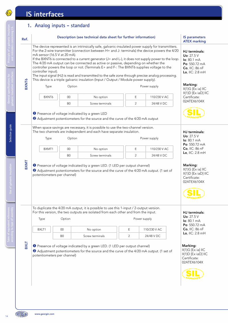
.IS interfaces1. Analog inputs - standard
Ref.Description (see technical data sheet for further information) IS parameters
ATEX marking
BX
NT6
The device represented is an intrinsically safe, galvanic-insulated power supply for transmitters.For the 2-wire transmitter (connection between H+ and J- terminals) the device powers the 4/20 mA sensor (16.5 V at 20 mA).If the BXNT6 is connected to a current generator (J+ and L-), it does not supply power to the loop.The 4/20 mA output can be connected as active or passive, depending on whether the controller powers the loop or not. (Terminals E+ and F-: The BXNT6 supplies voltage to the controller input).The input signal (HJ) is read and transmitted to the safe zone through precise analog processing.This device is a triple galvanic insulation (Input / Output / Module power supply).
Type Option Power supply
BXNT6 00 No option E 110/230 V AC
B0 Screw terminals 2 24/48 V DC
Presence of voltage indicated by a green LED Adjustment potentiometers for the source and the curve of the 4/20 mA output
HJ terminals:Uo: 27.5 VIo: 80.1 mAPo: 550.72 mACo, IIC: 86 nFLo, IIC: 2.8 mH
Marking:II(1)G [Ex ia] IICII(1)D [Ex iaD] IICCertificate: 02ATEX6104X
BX
MT
When space savings are necessary, it is possible to use the two-channel version.The two channels are independent and each have separate insulation.
Type Option Power supply
BXMT1 00 No option E 110/230 V AC
B0 Screw terminals 2 24/48 V DC
Presence of voltage indicated by a green LED. (1 LED per output channel) Adjustment potentiometers for the source and the curve of the 4/20 mA output. (1 set of potentiometers per channel)
HJ terminals:Uo: 27.5 VIo: 80.1 mAPo: 550.72 mACo, IIC: 86 nFLo, IIC: 2.8 mH
Marking:II(1)G [Ex ia] IICII(1)D [Ex iaD] IICCertificate: 02ATEX6104X
BX
LT
To duplicate the 4/20 mA output, it is possible to use this 1-input / 2-output version.For this version, the two outputs are isolated from each other and from the input.
Type Option Power supply
BXLT1 00 No option E 110/230 V AC
B0 Screw terminals 2 24/48 V DC
Presence of voltage indicated by a green LED. (1 LED per output channel) Adjustment potentiometers for the source and the curve of the 4/20 mA output. (1 set of potentiometers per channel)
HJ terminals:Uo: 27.5 VIo: 80.1 mAPo: 550.72 mACo, IIC: 86 nFLo, IIC: 2.8 mH
Marking:II(1)G [Ex ia] IICII(1)D [Ex iaD] IICCertificate: 02ATEX6104X

www.georgin.com15
Tabl
e of
equ
ival
ent
refe
renc
es
acco
rdin
g to
typ
e of
ass
embl
yUs
e of
gal
vani
c in
sula
tion
Sele
ctio
n gu
ide
Gene
ral s
peci
ficat
ions
for
ga
lvan
ic in
sula
tion
inte
rfac
esPr
inci
ple
of a
gal
vani
c in
sula
tion
and
rem
inde
rs c
once
rnin
g I.S
.
IS interfaces
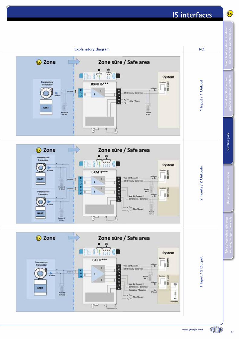
Explanatory diagram I/O
1 In
put
/ 1
Out
put
2 In
put
s /
2 O
utp
uts
1 In
put
/ 2
Out
put
16www.georgin.com
Tabl
e of
equ
ival
ent
refe
renc
es
acco
rdin
g to
typ
e of
ass
embl
yUs
e of
gal
vani
c in
sula
tion
Sele
ctio
n gu
ide
Gene
ral s
peci
ficat
ions
for
ga
lvan
ic in
sula
tion
inte
rfac
esPr
inci
ple
of a
gal
vani
c in
sula
tion
and
rem
inde
rs c
once
rnin
g I.S
.IS interfaces
Ref.Description (see technical data sheet for further information) IS parameters
ATEX marking
BX
NTI
6
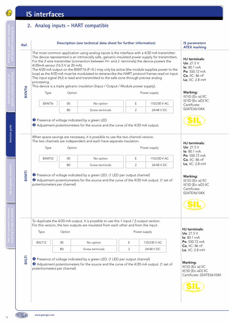
The most common application using analog inputs is the interface with a 4/20 mA transmitter:The device represented is an intrinsically safe, galvanic-insulated power supply for transmitters.For the 2-wire transmitter (connection between H+ and J- terminals) the device powers the 4/20mA sensor (16.5 V at 20 mA). The 4/20 mA output on the BXNT16 (F+E-) may only be active (the module supplies power to the loop) as the 4/20 mA must be modulated to retranscribe the HART protocol frames read on input.The input signal (HJ) is read and transmitted to the safe zone through precise analog processing.This device is a triple galvanic insulation (Input / Output / Module power supply).
Type Option Power supply
BXNTI6 00 No option E 110/230 V AC
B0 Screw terminals 2 24/48 V DC
Presence of voltage indicated by a green LED Adjustment potentiometers for the source and the curve of the 4/20 mA output.
HJ terminals:Uo: 27.5 VIo: 80.1 mAPo: 550.72 mACo, IIC: 86 nFLo, IIC: 2.8 mH
Marking:II(1)G [Ex ia] IICII(1)D [Ex iaD] IICCertificate: 02ATEX6104X
BX
MTI
When space savings are necessary, it is possible to use the two-channel version.The two channels are independent and each have separate insulation.
Type Option Power supply
BXMTI2 00 No option E 110/230 V AC
B0 Screw terminals 2 24/48 V DC
Presence of voltage indicated by a green LED. (1 LED per output channel) Adjustment potentiometers for the source and the curve of the 4/20 mA output. (1 set of potentiometers per channel)
HJ terminals:Uo: 27.5 VIo: 80.1 mAPo: 550.72 mACo, IIC: 86 nFLo, IIC: 2.8 mH
Marking:II(1)G [Ex ia] IICII(1)D [Ex iaD] IICCertificate: 02ATEX6104X
BX
LTI
To duplicate the 4/20 mA output, it is possible to use this 1-input / 2-output version.For this version, the two outputs are insulated from each other and from the input.
Type Option Power supply
BXLT12 00 No option E 110/230 V AC
B0 Screw terminals 2 24/48 V DC
Presence of voltage indicated by a green LED. (1 LED per output channel) Adjustment potentiometers for the source and the curve of the 4/20 mA output. (1 set of potentiometers per channel)
HJ terminals:Uo: 27.5 VIo: 80.1 mAPo: 550.72 mACo, IIC: 86 nFLo, IIC: 2.8 mH
Marking:II(1)G [Ex ia] IICII(1)D [Ex iaD] IICCertificate: 02ATEX6104X
2. Analog inputs - HART compatible
www.georgin.com17
Tabl
e of
equ
ival
ent
refe
renc
es
acco
rdin
g to
typ
e of
ass
embl
yUs
e of
gal
vani
c in
sula
tion
Sele
ctio
n gu
ide
Gene
ral s
peci
ficat
ions
for
ga
lvan
ic in
sula
tion
inte
rfac
esPr
inci
ple
of a
gal
vani
c in
sula
tion
and
rem
inde
rs c
once
rnin
g I.S
.
IS interfaces
Explanatory diagram I/O
1 In
put
/ 1
Out
put
2 In
put
s /
2 O
utp
uts
1 In
put
/ 2
Out
put
18www.georgin.com
Tabl
e of
equ
ival
ent
refe
renc
es
acco
rdin
g to
typ
e of
ass
embl
yUs
e of
gal
vani
c in
sula
tion
Sele
ctio
n gu
ide
Gene
ral s
peci
ficat
ions
for
ga
lvan
ic in
sula
tion
inte
rfac
esPr
inci
ple
of a
gal
vani
c in
sula
tion
and
rem
inde
rs c
once
rnin
g I.S
.IS interfaces
Ref.Description (see technical data sheet for further information) IS parameters
ATEX marking
BX
NT1
***-
00-0
0 (e
x)
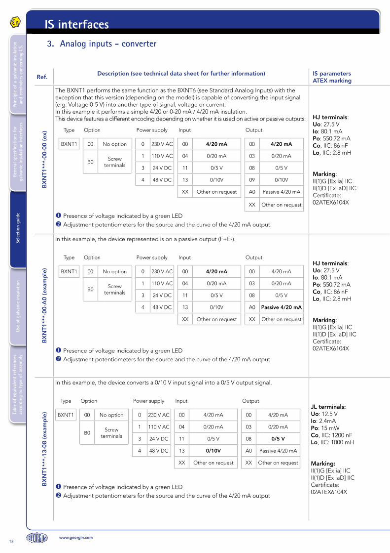
The BXNT1 performs the same function as the BXNT6 (see Standard Analog Inputs) with the exception that this version (depending on the model) is capable of converting the input signal (e.g. Voltage 0-5 V) into another type of signal, voltage or current.In this example it performs a simple 4/20 or 0-20 mA / 4/20 mA insulation.This device features a different encoding depending on whether it is used on active or passive outputs:
Type Option Power supply Input Output
BXNT1 00 No option 0 230 V AC 00 4/20 mA 00 4/20 mA
B0Screw
terminals
1 110 V AC 04 0/20 mA 03 0/20 mA
3 24 V DC 11 0/5 V 08 0/5 V
4 48 V DC 13 0/10V 09 0/10V
XX Other on request A0 Passive 4/20 mA
XX Other on request
Presence of voltage indicated by a green LED Adjustment potentiometers for the source and the curve of the 4/20 mA output.
HJ terminals:Uo: 27.5 VIo: 80.1 mAPo: 550.72 mACo, IIC: 86 nFLo, IIC: 2.8 mH
Marking:II(1)G [Ex ia] IICII(1)D [Ex iaD] IICCertificate: 02ATEX6104X
BX
NT1
***-
00-A
0 (e
xam
ple
)
In this example, the device represented is on a passive output (F+E-).
Type Option Power supply Input Output
BXNT1 00 No option 0 230 V AC 00 4/20 mA 00 4/20 mA
B0Screw
terminals
1 110 V AC 04 0/20 mA 03 0/20 mA
3 24 V DC 11 0/5 V 08 0/5 V
4 48 V DC 13 0/10V A0 Passive 4/20 mA
XX Other on request XX Other on request
Presence of voltage indicated by a green LED Adjustment potentiometers for the source and the curve of the 4/20 mA output
HJ terminals:Uo: 27.5 VIo: 80.1 mAPo: 550.72 mACo, IIC: 86 nFLo, IIC: 2.8 mH
Marking:II(1)G [Ex ia] IICII(1)D [Ex iaD] IICCertificate: 02ATEX6104X
BX
NT1
***-
13-0
8 (e
xam
ple
)
In this example, the device converts a 0/10 V input signal into a 0/5 V output signal.
Type Option Power supply Input Output
BXNT1 00 No option 0 230 V AC 00 4/20 mA 00 4/20 mA
B0Screw
terminals
1 110 V AC 04 0/20 mA 03 0/20 mA
3 24 V DC 11 0/5 V 08 0/5 V
4 48 V DC 13 0/10V A0 Passive 4/20 mA
XX Other on request XX Other on request
Presence of voltage indicated by a green LED Adjustment potentiometers for the source and the curve of the 4/20 mA output
JL terminals:Uo: 12.5 VIo: 2.4mAPo: 15 mWCo, IIC: 1200 nFLo, IIC: 1000 mH
Marking:II(1)G [Ex ia] IICII(1)D [Ex iaD] IICCertificate: 02ATEX6104X
3. Analog inputs - converter

www.georgin.com19
Tabl
e of
equ
ival
ent
refe
renc
es
acco
rdin
g to
typ
e of
ass
embl
yUs
e of
gal
vani
c in
sula
tion
Sele
ctio
n gu
ide
Gene
ral s
peci
ficat
ions
for
ga
lvan
ic in
sula
tion
inte
rfac
esPr
inci
ple
of a
gal
vani
c in
sula
tion
and
rem
inde
rs c
once
rnin
g I.S
.
IS interfaces
Explanatory diagram I/O
1 In
put
/ 1
act
ive
Out
put
1 In
put
/ 1
pas
sive
Out
put
1 In
put
/ 1
Out
put
(Co
nver
sio
n)

20www.georgin.com
Tabl
e of
equ
ival
ent
refe
renc
es
acco
rdin
g to
typ
e of
ass
embl
yUs
e of
gal
vani
c in
sula
tion
Sele
ctio
n gu
ide
Gene
ral s
peci
ficat
ions
for
ga
lvan
ic in
sula
tion
inte
rfac
esPr
inci
ple
of a
gal
vani
c in
sula
tion
and
rem
inde
rs c
once
rnin
g I.S
.IS interfaces
Ref.Description (see technical data sheet for further information) IS parameters
ATEX marking
BX
NI1
T
The BXNIT is a passive 4/20 mA signal isolator (it does not supply power to equipment in a hazardous area).The voltage source is located in the hazardous area: the module isolates the 4/20 input signal (J+H-) and sends it to a passive system in the safe area.When the signal is transferred from the hazardous area to the safe area, the transfer impedance specific to the BXNIT must be taken into account (see example on p. 34-35).
TypeNumber of channels Model Option
BXNI 1 1 channel T IS signal towards NIS 00 No option
B0 Screw terminals
Adjustment potentiometers of the 4/20 mA output curve (1 per channel).
HJ terminals:Ui: 66 VIi: 100 mACi: insignificantLi: insignificant
Marking:II(1)G [Ex ia] IICII(1)D [Ex iaD] IICCertificate: 02ATEX6104X
BX
NI2
T
2-channel version
TypeNumber of channels Model Option
BXNI 2 2 channels T IS signal towards NIS 00 No option
B0 Screw terminals
Adjustment potentiometers of the 4/20 mA output curve (1 per channel).
HJ terminals:Ui: 66 VIi: 100 mACi: insignificantLi: insignificant
Marking:II(1)G [Ex ia] IICII(1)D [Ex iaD] IICCertificate: 02ATEX6104X
BX
NI4
T
4-channel version
TypeNumber of channels Model Option
BXNI 4 4 channels T IS signal towards NIS 00 No option
B0 Screw terminals
Adjustment potentiometers of the 4/20 mA output curve (1 per channel).
HJ terminals:Ui: 66 VIi: 100 mACi: insignificantLi: insignificant
Marking:II(1)G [Ex ia] IICII(1)D [Ex iaD] IICCertificate: 02ATEX6104X
4. Analog inputs - isolator

www.georgin.com21
Tabl
e of
equ
ival
ent
refe
renc
es
acco
rdin
g to
typ
e of
ass
embl
yUs
e of
gal
vani
c in
sula
tion
Sele
ctio
n gu
ide
Gene
ral s
peci
ficat
ions
for
ga
lvan
ic in
sula
tion
inte
rfac
esPr
inci
ple
of a
gal
vani
c in
sula
tion
and
rem
inde
rs c
once
rnin
g I.S
.
IS interfaces
Explanatory diagram I/O
1 In
put
/ 1
Out
put
2 In
put
s /
2 O
utp
uts
4 In
put
s /
4 O
utp
uts

22www.georgin.com
Tabl
e of
equ
ival
ent
refe
renc
es
acco
rdin
g to
typ
e of
ass
embl
yUs
e of
gal
vani
c in
sula
tion
Sele
ctio
n gu
ide
Gene
ral s
peci
ficat
ions
for
ga
lvan
ic in
sula
tion
inte
rfac
esPr
inci
ple
of a
gal
vani
c in
sula
tion
and
rem
inde
rs c
once
rnin
g I.S
.IS interfaces
Ref.Description (see technical data sheet for further information) IS parameters
ATEX marking
RD
N11
0
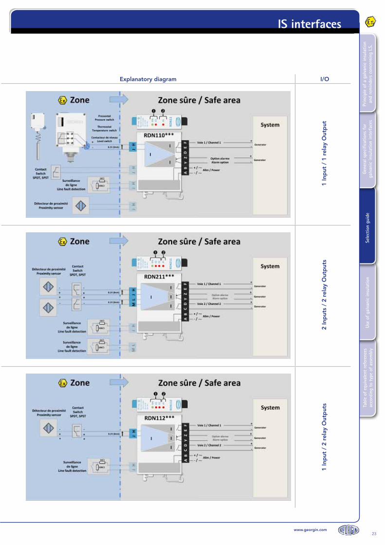
The RDN is an intrinsically safe, galvanic-isolated relay for switches or proximity sensors. The RDN supplies the switch in a hazardous area (8.2 V at 8 mA).The relay output (F E) is voltage-free.
TypeNumber of channels Options Power supply
RDN110
1 channel1 relay output
Inverter contact
00 No alarm 0 230 V AC
AL With alarm 1 110 V AC
B0 Screw terminals 2 24/48 V DC
BL Alarm + screw terminals 7 12 V DC
- -Other options
(see technical data sheet)
Green LED to indicate power is supplied to the module.Red LED to indicate activation of the output relay.
Red LED (AL) to indicate that the alarm transistor is conductive.It becomes conductive when the proximity sensor (Namur) input is outside of its operating range.
HJ terminals:Uo: 12 VIo: 25 mAPo: 150 mWCo: 1410 nFLo: 45 mH
Marking:II(1)G [Ex ia] IICII(1)D [Ex iaD] IICCertificate: 02ATEX6104X
RD
N21
1
Identical model to RDN110 but in 2-channel version.
TypeNumber of channels Options Power supply
RDN211
2 channels2 x 1 relay outputs
Inverter contact
00 No alarm 0 230 V AC
AL With alarm 1 110 V AC
B0 Screw terminals 224/48 V
DC
BL Alarm + screw terminals 7 12 V DC
- -Other options
(see technical data sheet)
Green LED to indicate power is supplied to the module. 2 x red LED to indicate activation of the output relays (C1 and C2).
Red LED (AL) to indicate that the alarm transistor is conductive.The alarm is activated when one of the two proximity sensors (Namur) indicates a fault.
HJ terminals:Uo: 12 VIo: 25 mAPo: 150 mWCo: 1410 nFLo: 45 mH
Marking:II(1)G [Ex ia] IICII(1)D [Ex iaD] IICCertificate: 02ATEX6104X
RD
N11
2
Identical model to the RDN110 but with 1 input and 2 simultaneous outputs.
TypeNumber of channels Options Power supply
RDN112
1 channel2 x 1 relay outputs
Switch contact
00 No alarm 0 230 V AC
AL With alarm 1 110 V AC
B0 Screw terminals 224/48 V
DC
BL Alarm + screw terminals 7 12 V DC
- -Other options
(see technical data sheet)
Green LED to indicate power is supplied to the module.2 x red LED to indicate activation of the simultaneous output relays (C1 and C2).
Red LED (AL) to indicate that the alarm transistor is conductive.It becomes conductive when the proximity sensor (Namur) input is outside of its operating range.
HJ terminals:Uo: 12 VIo: 25 mAPo: 150 mWCo: 1410 nFLo: 45 mH
Marking:II(1)G [Ex ia] IICII(1)D [Ex iaD] IICCertificate: 02ATEX6104X
5. Digital inputs - relay outputs
www.georgin.com23
Tabl
e of
equ
ival
ent
refe
renc
es
acco
rdin
g to
typ
e of
ass
embl
yUs
e of
gal
vani
c in
sula
tion
Sele
ctio
n gu
ide
Gene
ral s
peci
ficat
ions
for
ga
lvan
ic in
sula
tion
inte
rfac
esPr
inci
ple
of a
gal
vani
c in
sula
tion
and
rem
inde
rs c
once
rnin
g I.S
.
IS interfaces
Explanatory diagram I/O
1 In
put
/ 1
rel
ay O
utp
ut2
Inp
uts
/ 2
rela
y O
utp
uts
1 In
put
/ 2
rel
ay O
utp
uts

24www.georgin.com
Tabl
e of
equ
ival
ent
refe
renc
es
acco
rdin
g to
typ
e of
ass
embl
yUs
e of
gal
vani
c in
sula
tion
Sele
ctio
n gu
ide
Gene
ral s
peci
ficat
ions
for
ga
lvan
ic in
sula
tion
inte
rfac
esPr
inci
ple
of a
gal
vani
c in
sula
tion
and
rem
inde
rs c
once
rnin
g I.S
.IS interfaces
Ref.Description (see technical data sheet for further information) IS parameters
ATEX marking
RD
N10
0
The RDN is an intrinsically safe, galvanic-isolated relay for switches or proximity sensors. The RDN powers switches in a hazardous area (8.2 V at 8 mA).Here the relay output (F E) is transistor, in contrast to the RDN110 (equipped with a relay).
TypeNumber of channels Options Power supply
RDN100
1 channel1 transistor output
00 No alarm 0 230 V AC
AL With alarm 1 110 V AC
B0 Screw terminals 2 24/48 V DC
BL Alarm + screw terminals 7 12 V DC
- -Other options
(see technical data sheet)
Green LED to indicate power is supplied to the module.Red LED to indicate that the output transistor is conductive.
Red LED (AL) to indicate that the alarm transistor is conductive.It becomes conductive when the proximity sensor (Namur) input is outside of its operating range.
HJ terminals:Uo: 12 VIo: 25 mAPo: 150 mWCo: 1410 nFLo: 45 mH
Marking:II(1)G [Ex ia] IICII(1)D [Ex iaD] IICCertificate:02ATEX6104X
RD
N21
0
Identical model to the RDN110 but with 1 input and 2 simultaneous outputs.
TypeNumber of channels Options Power supply
RDN210
2 channels2 x 1 transistor
outputs
00 No alarm 0 230 V AC
AL With alarm 1 110 V AC
B0 Screw terminals 224/48 V
DC
BL Alarm + screw terminals 7 12 V DC
- -Other options
(see technical data sheet)
Green LED to indicate power is supplied to the module. 2 x red LED to indicate that the output transistors (C1 and C2) are conductive.
Red LED (AL) to indicate that the alarm transistor is conductive.The alarm is activated when one of the two proximity sensors (Namur) indicates a fault.
HJ terminals:Uo: 12 VIo: 25 mAPo: 150 mWCo: 1410 nFLo: 45 mH
Marking:II(1)G [Ex ia] IICII(1)D [Ex iaD] IICCertificate: 02ATEX6104X
RD
N10
2
Identical model to the RDN110 but with 1 input and 2 simultaneous outputs.
TypeNumber of channels Options Power supply
RDN102
1 channel2 x 1 transistor
outputs
00 No alarm 0 230 V AC
AL With alarm 1 110 V AC
B0 Screw terminals 224/48 V
DC
BL Alarm + screw terminals 7 12 V DC
- -Other options
(see technical data sheet)
Green LED to indicate power is supplied to the module.2 x red LED to indicate activation of the simultaneous output relays (C1 and C2).
Red LED (AL) to indicate that the alarm transistor is conductive.It becomes conductive when the proximity sensor (Namur) input is outside of its operating range.
HJ terminals:Uo: 12VIo: 25mAPo: 150mWCo: 1410 nFLo: 45 mH
Marking:II(1)G [Ex ia] IICII(1)D [Ex iaD] IICCertificate: 02ATEX6104X
6. Digital inputs - transistor outputs

www.georgin.com25
Tabl
e of
equ
ival
ent
refe
renc
es
acco
rdin
g to
typ
e of
ass
embl
yUs
e of
gal
vani
c in
sula
tion
Sele
ctio
n gu
ide
Gene
ral s
peci
ficat
ions
for
ga
lvan
ic in
sula
tion
inte
rfac
esPr
inci
ple
of a
gal
vani
c in
sula
tion
and
rem
inde
rs c
once
rnin
g I.S
.
IS interfaces
Explanatory diagram I/O
1 In
put
/ 1
tra
nsis
tor
Out
put
2 In
put
s /
2 tr
ansi
sto
r O
utp
uts
1 In
put
/ 2
tra
nsis
tor
Out
put
s

26www.georgin.com
Tabl
e of
equ
ival
ent
refe
renc
es
acco
rdin
g to
typ
e of
ass
embl
yUs
e of
gal
vani
c in
sula
tion
Sele
ctio
n gu
ide
Gene
ral s
peci
ficat
ions
for
ga
lvan
ic in
sula
tion
inte
rfac
esPr
inci
ple
of a
gal
vani
c in
sula
tion
and
rem
inde
rs c
once
rnin
g I.S
.IS interfaces
Ref.Description (see technical data sheet for further information) IS parameters
ATEX marking
RD
N31
0
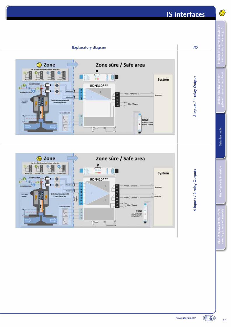
The RDN310 is an intrinsically safe, galvanic-isolated bistable relay for switches or proximity sensors.It is used in the example shown opposite to interface stroke-end switches or proximity sensors on a solenoid valve.The benefit of this device is that it enables the last state detected on the input to be memorised on the output.When the first proximity sensor changes state, the RDN relay input detects this and the output relay also changes state. The output relay retains its state as long as the second RDN input does not detect a change of state by proximity sensor no. 2.
TypeNumber of channels Options Power supply
RDN 310 2 Inputs - 1 Output 00 No alarm 0 230 V AC
B0 Screw terminals 1 110 V AC
2 24/48 V DC
Green LED to indicate power is supplied to the module.Red LED to indicate that the C1 output relay is excited.
HJ terminals:Uo: 8.6 VIo: 9 mAPo: 19 mWCo, IIC: 6200 nFLo, IIC: 350 mH
Marking:II(1)G [Ex ia] IICII(1)D [Ex iaD] IICCertificate: 02ATEX6104X
RD
N41
0
The RDN410 is an intrinsically safe, galvanic-isolated bistable relay for switches or proximity sensors. Identical to the RDN310, it has two channels (i.e. 4 inputs).
TypeNumber of channels Options Power supply
RDN 410 4 Inputs - 2 Outputs 00 No alarm 0 230 V AC
B0 Screw terminals 1 110 V AC
224/48 V
DC
Green LED to indicate power is supplied to the module.2 x red LED to indicate that the output relays (C1 and C2) are excited.
HJ terminals:Uo: 8.6 VIo: 9 mAPo: 19 mWCo, IIC: 6200 nFLo, IIC: 350 mH
Marking:II(1)G [Ex ia] IICII(1)D [Ex iaD] IICCertificate: 02ATEX6104X
7. Digital inputs - output relays with input memory
www.georgin.com27
Tabl
e of
equ
ival
ent
refe
renc
es
acco
rdin
g to
typ
e of
ass
embl
yUs
e of
gal
vani
c in
sula
tion
Sele
ctio
n gu
ide
Gene
ral s
peci
ficat
ions
for
ga
lvan
ic in
sula
tion
inte
rfac
esPr
inci
ple
of a
gal
vani
c in
sula
tion
and
rem
inde
rs c
once
rnin
g I.S
.
IS interfaces
Explanatory diagram I/O
2 In
put
s /
1 re
lay
Out
put
4 In
put
s /
2 re
lay
Out
put
s

28www.georgin.com
Tabl
e of
equ
ival
ent
refe
renc
es
acco
rdin
g to
typ
e of
ass
embl
yUs
e of
gal
vani
c in
sula
tion
Sele
ctio
n gu
ide
Gene
ral s
peci
ficat
ions
for
ga
lvan
ic in
sula
tion
inte
rfac
esPr
inci
ple
of a
gal
vani
c in
sula
tion
and
rem
inde
rs c
once
rnin
g I.S
.IS interfaces
Ref.Description (see technical data sheet for further information) IS parameters
ATEX marking
RD
N31
0
The RDN213W is a digital signal isolator with two independent channels.This intrinsically safe, galvanic-insulated separator uses opto-isolators to transfer the signal from the hazardous area to the safe area.The module operates without a power supply: the voltage source comes from the hazardous area.
Type Model Power supply Input Output
RDN 213Opto-isolator
IS input / NIS outputW
2 channels
00Cage clamp
terminals3 24 V DC
B0 Screw terminals 7 12 V DC
8 5 V DC
2 x red LED to indicate that the output transistors (opto-isolators) are conductive.
Maximum current on intrinsic safety circuit:100 mA
Marking:II(1)G [Ex ia] IICII(1)D [Ex iaD] IICCertificate: 02ATEX6104X
RD
N41
0
Identical to the RDN213W, the RDN213V has four independent channels.
Type Model Power supply Input Output
RDN 213Opto-isolator
IS input / NIS outputV
4 channels
00Cage clamp
terminals3 24 V DC
B0 Screw terminals 7 12 V DC
8 5 V DC
4 x red LED to indicate that the output transistors (opto-isolators) are conductive.
Maximum current on intrinsic safety circuit:100 mA
Marking:II(1)G [Ex ia] IICII(1)D [Ex iaD] IICCertificate: 02ATEX6104X
8. Digital inputs - signal isolator

www.georgin.com29
Tabl
e of
equ
ival
ent
refe
renc
es
acco
rdin
g to
typ
e of
ass
embl
yUs
e of
gal
vani
c in
sula
tion
Sele
ctio
n gu
ide
Gene
ral s
peci
ficat
ions
for
ga
lvan
ic in
sula
tion
inte
rfac
esPr
inci
ple
of a
gal
vani
c in
sula
tion
and
rem
inde
rs c
once
rnin
g I.S
.
IS interfaces
Explanatory diagram I/O
2 In
put
s /
2 O
pto
-iso
lato
r O
utp
uts
4 In
put
s /
4 O
pto
-iso
lato
r O
utp
uts

30www.georgin.com
Tabl
e of
equ
ival
ent
refe
renc
es
acco
rdin
g to
typ
e of
ass
embl
yUs
e of
gal
vani
c in
sula
tion
Sele
ctio
n gu
ide
Gene
ral s
peci
ficat
ions
for
ga
lvan
ic in
sula
tion
inte
rfac
esPr
inci
ple
of a
gal
vani
c in
sula
tion
and
rem
inde
rs c
once
rnin
g I.S
.IS interfaces
Ref.Description (see technical data sheet for further information) IS parameters
ATEX marking
BX
NA
1***
-00-
00
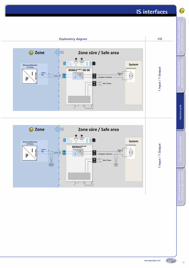
The BXNA1 is an intrinsically safe, galvanic insulated converter for actuators. It is used to transmit a 4/20 mA signal (or other depending on the model selected) to a hazardous area.
Type Model Power supply Input Output
BXNA1 00 No option 0 230 V AC 00 4/20 mA 00 4/20 mA
B0 Screw terminals 1 110 V AC 02 0/5 mA
3 24 V DC 04 0/20 mA
4 48 V DC 08 -10/+10V
11 0/5 V
13 0/10V
XXOthers on
request
Presence of voltage indicated by a green LED Adjustment potentiometers for the source and the curve of the 4/20 mA output.
HJ terminals:Uo: 23.5 VIo: 97 mAPo: 560 mWCo, IIC: 132 nFLo, IIC: 5 mH
Marking:II(1)G [Ex ia] IICII(1)D [Ex iaD] IICCertificate: 02ATEX6104X
BX
NA
I2**
*
The BXNAI2 is an intrinsically safe, galvanic-insulated converter for intelligent actuators (HART protocol).Identical to the BXNA1, it is only available in a 4/20 mA / 4/20 mA version as it is dedicated to actuators that use the HART protocol.
Type Model Power supply
BXNAI2 00 No option 0 230 V AC
B0 Screw terminals 1 110 V AC
3 24 V DC
4 48 V DC
Presence of voltage indicated by a green LED Adjustment potentiometers for the source and the curve of the 4/20 mA output.
HJ terminals:Uo: 23.5 VIo: 97 mAPo: 560 mWCo, IIC: 132 nFLo, IIC: 5 mH
Marking:II(1)G [Ex ia] IICII(1)D [Ex iaD] IICCertificate: 02ATEX6104X
9. Analog inputs - converter
www.georgin.com31
Tabl
e of
equ
ival
ent
refe
renc
es
acco
rdin
g to
typ
e of
ass
embl
yUs
e of
gal
vani
c in
sula
tion
Sele
ctio
n gu
ide
Gene
ral s
peci
ficat
ions
for
ga
lvan
ic in
sula
tion
inte
rfac
esPr
inci
ple
of a
gal
vani
c in
sula
tion
and
rem
inde
rs c
once
rnin
g I.S
.
IS interfaces
Explanatory diagram I/O
1 In
put
/ 1
Out
put
1 In
put
/ 1
Out
put

32www.georgin.com
Tabl
e of
equ
ival
ent
refe
renc
es
acco
rdin
g to
typ
e of
ass
embl
yUs
e of
gal
vani
c in
sula
tion
Sele
ctio
n gu
ide
Gene
ral s
peci
ficat
ions
for
ga
lvan
ic in
sula
tion
inte
rfac
esPr
inci
ple
of a
gal
vani
c in
sula
tion
and
rem
inde
rs c
once
rnin
g I.S
.IS interfaces
Ref.Description (see technical data sheet for further information) IS parameters
ATEX marking
BX
NI1
A
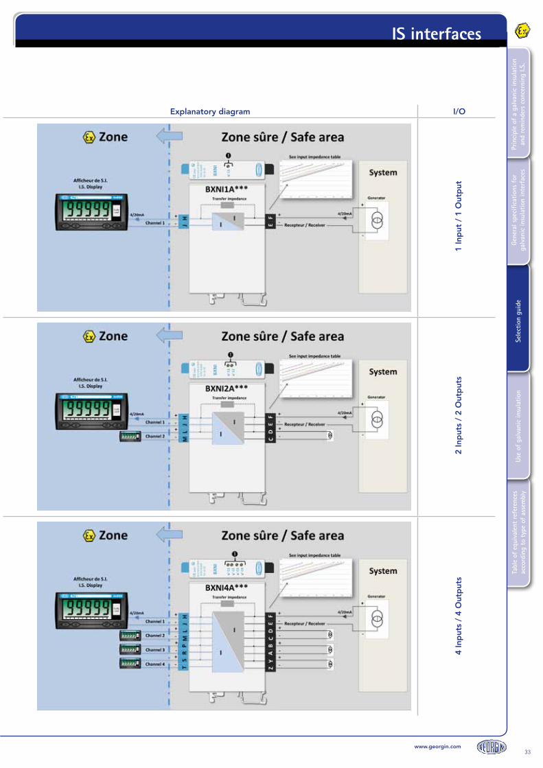
The BXNI1A is a passive, self-powered 4/20 mA signal isolator.It is used to send a 4/20 mA signal generated in a safe area into a hazardous area.When the signal is transferred from the safe area to the hazardous area, the transfer impedance specific to the BXNIA (see example on p. 34-35) must be taken into account.
TypeNumber of channels Model Option
BXNI 1 1 channel A1 Impedance: 510Ω 00 No option
A2 Impedance: 450Ω B0 Screw terminals
A3 Impedance: 390Ω
A4 Impedance: 330Ω
A5 Impedance: 270Ω
A6 Impedance: 281Ω
A7 Impedance: 300Ω
Adjustment potentiometers of the 4/20 mA output curve (1 per channel).
HJ terminals:See technical data sheet(depends on the version)
Marking:II(1)G [Ex ia] IICII(1)D [Ex iaD] IICCertificate: 02ATEX6104X
BX
NI2
A
2-channel version
TypeNumber of channels Model Option
BXNI 2 2 channels A1 Impedance: 510Ω 00 No option
A2 Impedance: 450Ω B0 Screw terminals
A3 Impedance: 390Ω
A4 Impedance: 330Ω
A5 Impedance: 270Ω
A6 Impedance: 281Ω
A7 Impedance: 300Ω
Adjustment potentiometers of the 4/20 mA output curve (1 per channel).
HJ terminals:See technical data sheet(depends on the version)
Marking:II(1)G [Ex ia] IICII(1)D [Ex iaD] IICCertificate: 02ATEX6104X
BX
NI4
A
2-channel version
TypeNumber of channels Model Option
BXNI 4 4 channels A1 Impedance: 510Ω 00 No option
A2 Impedance: 450Ω B0 Screw terminals
A3 Impedance: 390Ω
A4 Impedance: 330Ω
A5 Impedance: 270Ω
A6 Impedance: 281Ω
A7 Impedance: 300Ω
Adjustment potentiometers of the 4/20 mA output curve (1 per channel).
HJ terminals:See technical data sheet(depends on the version)
Marking:II(1)G [Ex ia] IICII(1)D [Ex iaD] IICCertificate: 02ATEX6104X
10. Analog output - isolator
www.georgin.com33
Tabl
e of
equ
ival
ent
refe
renc
es
acco
rdin
g to
typ
e of
ass
embl
yUs
e of
gal
vani
c in
sula
tion
Sele
ctio
n gu
ide
Gene
ral s
peci
ficat
ions
for
ga
lvan
ic in
sula
tion
inte
rfac
esPr
inci
ple
of a
gal
vani
c in
sula
tion
and
rem
inde
rs c
once
rnin
g I.S
.
IS interfaces
Explanatory diagram I/O
1 In
put
/ 1
Out
put
2 In
put
s /
2 O
utp
uts
4 In
put
s /
4 O
utp
uts

34www.georgin.com
Tabl
e of
equ
ival
ent
refe
renc
es
acco
rdin
g to
typ
e of
ass
embl
yUs
e of
gal
vani
c in
sula
tion
Sele
ctio
n gu
ide
Gene
ral s
peci
ficat
ions
for
ga
lvan
ic in
sula
tion
inte
rfac
esPr
inci
ple
of a
gal
vani
c in
sula
tion
and
rem
inde
rs c
once
rnin
g I.S
.IS interfaces
11. Impedance transfer table (BXNI*T and BXNI*A)
Impedance values for each version of the BXNI
BXNI version A1 A2 A3 A4 A5 A6 A7 T
Impedance transfer
510 Ω 450 Ω 390 Ω 330 Ω 270 Ω 281 Ω 300 Ω 330 Ω
Input impedance vs. output impedance
Out. In. Out. In. Out. In. Out. In. Out. In. Out. In. Out. In. Out. In.
Min Ω 0 510 0 450 0 390 0 330 0 270 0 281 0 300 0 330
Max Ω 120 630 180 630 240 630 300 630 360 630 349 630 330 630 300 630
www.georgin.com35
Tabl
e of
equ
ival
ent
refe
renc
es
acco
rdin
g to
typ
e of
ass
embl
yUs
e of
gal
vani
c in
sula
tion
Sele
ctio
n gu
ide
Gene
ral s
peci
ficat
ions
for
ga
lvan
ic in
sula
tion
inte
rfac
esPr
inci
ple
of a
gal
vani
c in
sula
tion
and
rem
inde
rs c
once
rnin
g I.S
.
IS interfaces
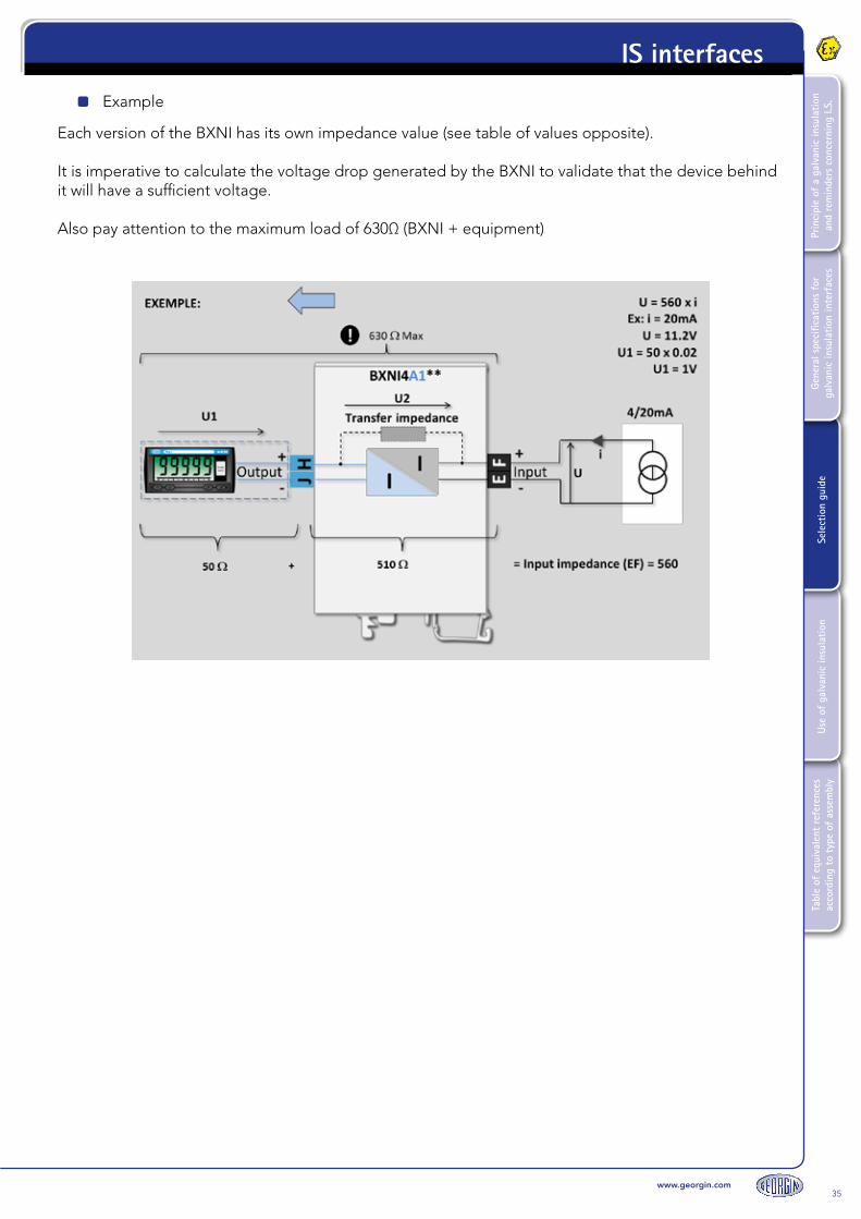
Example
Each version of the BXNI has its own impedance value (see table of values opposite).
It is imperative to calculate the voltage drop generated by the BXNI to validate that the device behind it will have a sufficient voltage.
Also pay attention to the maximum load of 630Ω (BXNI + equipment)

36www.georgin.com
Tabl
e of
equ
ival
ent
refe
renc
es
acco
rdin
g to
typ
e of
ass
embl
yUs
e of
gal
vani
c in
sula
tion
Sele
ctio
n gu
ide
Gene
ral s
peci
ficat
ions
for
ga
lvan
ic in
sula
tion
inte
rfac
esPr
inci
ple
of a
gal
vani
c in
sula
tion
and
rem
inde
rs c
once
rnin
g I.S
.IS interfaces
Ref.Description (see technical data sheet for further information) IS parameters
ATEX marking
BX
NE
**0*
**
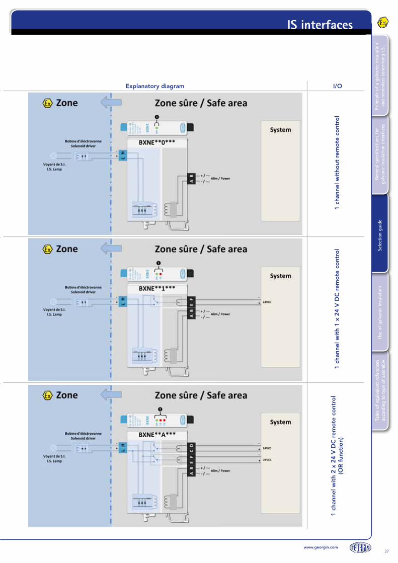
The BXNE is an intrinsically safe power supply.The BNXE**0 version provides constant power. It is not equipped with a remote control.
Type ModelNumber of channels Options Power supply
BXNE
**
Voltage and output current (depending on
curve)
01 channel
Without remote control
00 No option E 110 / 230 V AC
B0 Screw terminals 2 24/48 V DC
Green LED to indicate power is supplied to the module.
LH terminals:See BXNE curves(depends on the version)
Marking:II(1)G [Ex ia] IICII(1)D [Ex iaD] IICCertificate: 02ATEX6104X
BX
NE
**1*
**
The BXNE is an intrinsically safe power supply.The BXNE**1 version is equipped with a 24 V DC remote control (E+F-). A 24 V input voltage (E+F-) therefore actuates the relay, which actuates the output (L+H-).
Type ModelNumber of channels Options Power supply
BXNE
**
Voltage and output current (depending on
curve)
11 channel
With one 24 V DC remote control
00 No option E 110 / 230 V AC
B0 Screw terminals 2 24/48 V DC
Green LED to indicate power is supplied to the module.Red LED to indicate the activation of the 24 V DC remote control (E+F-)
LH terminals:See BXNE curves(depends on the version)
Marking:II(1)G [Ex ia] IICII(1)D [Ex iaD] IICCertificate: 02ATEX6104X
BX
NE
** A
***
The BXNE is an intrinsically safe power supply.The BXNE**A version is equipped with two 24 V DC remote controls (E+F-) and (C+D-).A 24 V DC voltage on (E+F-) or on (C+D-) activates the output (L+H-).
Type ModelNumber of channels Options Power supply
BXNE
**
Voltage and output current (depending on
curve)
A
1 channel2 x 24 V DC remote
controls(OR function)
00 No option E 110 / 230 V AC
B0 Screw terminals 2 24/48 V DC
Green LED to indicate power is supplied to the module.2 x red LED to indicate activation of the 24 V DC controls (1 LED per control).
LH terminals:See BXNE curves(depends on the version)
Marking:II(1)G [Ex ia] IICII(1)D [Ex iaD] IICCertificate: 02ATEX6104X
12. Digital outputs - 1 channel power supplies
www.georgin.com37
Tabl
e of
equ
ival
ent
refe
renc
es
acco
rdin
g to
typ
e of
ass
embl
yUs
e of
gal
vani
c in
sula
tion
Sele
ctio
n gu
ide
Gene
ral s
peci
ficat
ions
for
ga
lvan
ic in
sula
tion
inte
rfac
esPr
inci
ple
of a
gal
vani
c in
sula
tion
and
rem
inde
rs c
once
rnin
g I.S
.
IS interfaces
Explanatory diagram I/O
1 ch
anne
l wit
hout
rem
ote
co
ntro
l1
chan
nel w
ith
1 x
24 V
DC
rem
ote
co
ntro
l1
chan
nel w
ith
2 x
24 V
DC
rem
ote
co
ntro
l(O
R f
unct
ion)
Ref.Description (see technical data sheet for further information) IS parameters
ATEX marking
BX
NE
**0*
**
The BXNE is an intrinsically safe power supply.The BNXE**0 version provides constant power. It is not equipped with a remote control.
Type ModelNumber of channels Options Power supply
BXNE
**
Voltage and output current (depending on
curve)
01 channel
Without remote control
00 No option E 110 / 230 V AC
B0 Screw terminals 2 24/48 V DC
Green LED to indicate power is supplied to the module.
LH terminals:See BXNE curves(depends on the version)
Marking:II(1)G [Ex ia] IICII(1)D [Ex iaD] IICCertificate: 02ATEX6104X
BX
NE
**1*
**
The BXNE is an intrinsically safe power supply.The BXNE**1 version is equipped with a 24 V DC remote control (E+F-). A 24 V input voltage (E+F-) therefore actuates the relay, which actuates the output (L+H-).
Type ModelNumber of channels Options Power supply
BXNE
**
Voltage and output current (depending on
curve)
11 channel
With one 24 V DC remote control
00 No option E 110 / 230 V AC
B0 Screw terminals 2 24/48 V DC
Green LED to indicate power is supplied to the module.Red LED to indicate the activation of the 24 V DC remote control (E+F-)
LH terminals:See BXNE curves(depends on the version)
Marking:II(1)G [Ex ia] IICII(1)D [Ex iaD] IICCertificate: 02ATEX6104X
BX
NE
** A
***
The BXNE is an intrinsically safe power supply.The BXNE**A version is equipped with two 24 V DC remote controls (E+F-) and (C+D-).A 24 V DC voltage on (E+F-) or on (C+D-) activates the output (L+H-).
Type ModelNumber of channels Options Power supply
BXNE
**
Voltage and output current (depending on
curve)
A
1 channel2 x 24 V DC remote
controls(OR function)
00 No option E 110 / 230 V AC
B0 Screw terminals 2 24/48 V DC
Green LED to indicate power is supplied to the module.2 x red LED to indicate activation of the 24 V DC controls (1 LED per control).
LH terminals:See BXNE curves(depends on the version)
Marking:II(1)G [Ex ia] IICII(1)D [Ex iaD] IICCertificate: 02ATEX6104X

38www.georgin.com
Tabl
e of
equ
ival
ent
refe
renc
es
acco
rdin
g to
typ
e of
ass
embl
yUs
e of
gal
vani
c in
sula
tion
Sele
ctio
n gu
ide
Gene
ral s
peci
ficat
ions
for
ga
lvan
ic in
sula
tion
inte
rfac
esPr
inci
ple
of a
gal
vani
c in
sula
tion
and
rem
inde
rs c
once
rnin
g I.S
.IS interfaces
Ref.Description (see technical data sheet for further information) IS parameters
ATEX marking
BX
NE
**4*
**
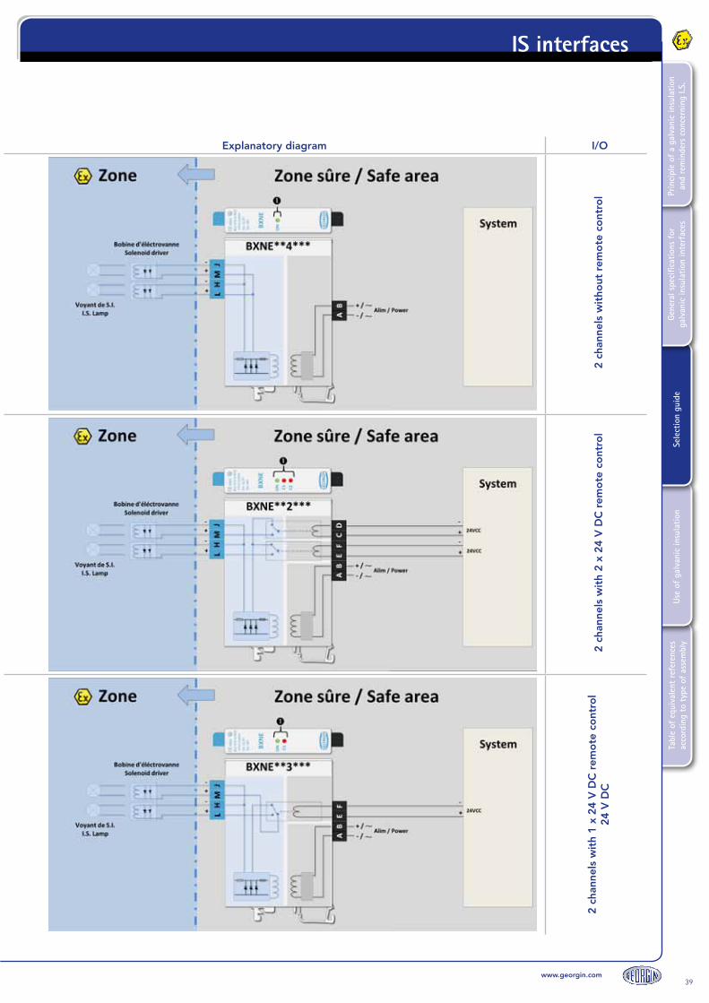
The BXNE is an intrinsically safe power supply.The BXNE**4 version provides constant power to both channels (L+H-) and (M+J-).It is not equipped with a remote control.Caution: The same power unit supplies both channels. The power specified on the BXNE curve is therefore shared by both channels.
Type ModelNumber of channels Options Power supply
BXNE
**
Voltage and output current (depending on
curve)
42 channels
Without remote control
00 No option E 110 / 230 V AC
B0 Screw terminals 2 24/48 V DC
Green LED to indicate power is supplied to the module.
LH terminals:See BXNE curves(depends on the version)
Marking:II(1)G [Ex ia] IICII(1)D [Ex iaD] IICCertificate: 02ATEX6104X
BX
NE
**2*
**
The BXNE is an intrinsically safe power supply.The BXNE**2 version is equipped with a 24 V DC remote control on each channel.A 24 V voltage on terminals (C+D-) actuates output (M+J-)A 24 V voltage on terminals (E+F-) actuates output (L+H-)Caution: The same power unit supplies both channels. The power specified on the BXNE curve is therefore shared by both channels.
Type ModelNumber of channels Options Power supply
BXNE
**
Voltage and output current (depending on
curve)
22 channels
With two 24 V DC remote controls
00 No option E 110 / 230 V AC
B0 Screw terminals 2 24/48 V DC
Green LED to indicate power is supplied to the module.2 x red LED to indicate activation of the 24 V DC controls (1 LED per control).
LH terminals:See BXNE curves(depends on the version)
Marking:II(1)G [Ex ia] IICII(1)D [Ex iaD] IICCertificate: 02ATEX6104X
BX
NE
** 3
***
The BXNE is an intrinsically safe power supply.The BXNE**3 version is equipped with a 24V DC remote control that actuates outputs alternately: either (L+H-) or (M+J-).
Type ModelNumber of channels Options Power supply
BXNE
**
Voltage and output current (depending on
curve)
32 alternate channelsWith one 24 V DC
remote control
00 No option E 110 / 230 V AC
B0 Screw terminals 2 24/48 V DC
Green LED to indicate power is supplied to the module.Red LED to indicate the activation of the 24 V DC remote control (E+F-)
LH terminals:See BXNE curves(depends on the version)
Marking:II(1)G [Ex ia] IICII(1)D [Ex iaD] IICCertificate: 02ATEX6104X
13. Digital outputs - 2-channel power supplies controlled by 24 V DC
www.georgin.com39
Tabl
e of
equ
ival
ent
refe
renc
es
acco
rdin
g to
typ
e of
ass
embl
yUs
e of
gal
vani
c in
sula
tion
Sele
ctio
n gu
ide
Gene
ral s
peci
ficat
ions
for
ga
lvan
ic in
sula
tion
inte
rfac
esPr
inci
ple
of a
gal
vani
c in
sula
tion
and
rem
inde
rs c
once
rnin
g I.S
.
IS interfaces
Explanatory diagram I/O
2 ch
anne
ls w
itho
ut r
emo
te c
ont
rol
2 ch
anne
ls w
ith
2 x
24 V
DC
rem
ote
co
ntro
l2
chan
nels
wit
h 1
x 24
V D
C r
emo
te c
ont
rol
24 V
DC

40www.georgin.com
Tabl
e of
equ
ival
ent
refe
renc
es
acco
rdin
g to
typ
e of
ass
embl
yUs
e of
gal
vani
c in
sula
tion
Sele
ctio
n gu
ide
Gene
ral s
peci
ficat
ions
for
ga
lvan
ic in
sula
tion
inte
rfac
esPr
inci
ple
of a
gal
vani
c in
sula
tion
and
rem
inde
rs c
once
rnin
g I.S
.IS interfaces
Ref.Description (see technical data sheet for further information) IS parameters
ATEX marking
BX
NE
**C
***
The BXNE is an intrinsically safe power supply.The BXNE**C version is equipped with a relay remote control on each channel.A contact on terminals (C+D-) actuates output (M+J-)A contact on terminals (E+F-) actuates output (L+H-)Caution: The same power unit supplies both channels. The power specified on the BXNE curve is therefore shared by both channels.
Type ModelNumber of channels Options Power supply
BXNE
**
Voltage and output current (depending on
curve)
C2 channels
With two contact remote controls
00 No option 2 24/48 V DC
B0 Screw terminals
Green LED to indicate power is supplied to the module.2 x red LED to indicate activation of the contact controls (1 LED per control).
LH terminals:See BXNE curves(depends on the version)
Marking:II(1)G [Ex ia] IICII(1)D [Ex iaD] IICCertificate: 02ATEX6104X
BX
NE
**D
***
The BXNE is an intrinsically safe power supply.The BXNE**D version is equipped with a relay remote control that actuates outputs alternately: either (L+H-) or (M+J-).
Type ModelNumber of channels Options Power supply
BXNE
**
Voltage and output current (depending on
curve)
D2 alternate channels
With 1 contact remote control
00 No option 2 24/48 V DC
B0 Screw terminals
Green LED to indicate power is supplied to the module.Red LED to indicate the activation of the contact remote control (E+F-)
LH terminals:See BXNE curves(depends on the version)
Marking:II(1)G [Ex ia] IICII(1)D [Ex iaD] IICCertificate: 02ATEX6104X
14. Digital outputs - 2-channel power supplies controlled by contact

www.georgin.com41
Tabl
e of
equ
ival
ent
refe
renc
es
acco
rdin
g to
typ
e of
ass
embl
yUs
e of
gal
vani
c in
sula
tion
Sele
ctio
n gu
ide
Gene
ral s
peci
ficat
ions
for
ga
lvan
ic in
sula
tion
inte
rfac
esPr
inci
ple
of a
gal
vani
c in
sula
tion
and
rem
inde
rs c
once
rnin
g I.S
.
IS interfaces
Explanatory diagram I/O
2 ch
anne
ls w
ith
2 co
ntac
t re
mo
te c
ont
rols
2 al
tern
ate
chan
nels
wit
h 1
cont
act
rem
ote
co
ntro
l
Ref.Description (see technical data sheet for further information) IS parameters
ATEX marking
BX
NE
**C
***
The BXNE is an intrinsically safe power supply.The BXNE**C version is equipped with a relay remote control on each channel.A contact on terminals (C+D-) actuates output (M+J-)A contact on terminals (E+F-) actuates output (L+H-)Caution: The same power unit supplies both channels. The power specified on the BXNE curve is therefore shared by both channels.
Type ModelNumber of channels Options Power supply
BXNE
**
Voltage and output current (depending on
curve)
C2 channels
With two contact remote controls
00 No option 2 24/48 V DC
B0 Screw terminals
Green LED to indicate power is supplied to the module.2 x red LED to indicate activation of the contact controls (1 LED per control).
LH terminals:See BXNE curves(depends on the version)
Marking:II(1)G [Ex ia] IICII(1)D [Ex iaD] IICCertificate: 02ATEX6104X
BX
NE
**D
***
The BXNE is an intrinsically safe power supply.The BXNE**D version is equipped with a relay remote control that actuates outputs alternately: either (L+H-) or (M+J-).
Type ModelNumber of channels Options Power supply
BXNE
**
Voltage and output current (depending on
curve)
D2 alternate channels
With 1 contact remote control
00 No option 2 24/48 V DC
B0 Screw terminals
Green LED to indicate power is supplied to the module.Red LED to indicate the activation of the contact remote control (E+F-)
LH terminals:See BXNE curves(depends on the version)
Marking:II(1)G [Ex ia] IICII(1)D [Ex iaD] IICCertificate: 02ATEX6104X
42www.georgin.com
Tabl
e of
equ
ival
ent
refe
renc
es
acco
rdin
g to
typ
e of
ass
embl
yUs
e of
gal
vani
c in
sula
tion
Sele
ctio
n gu
ide
Gene
ral s
peci
ficat
ions
for
ga
lvan
ic in
sula
tion
inte
rfac
esPr
inci
ple
of a
gal
vani
c in
sula
tion
and
rem
inde
rs c
once
rnin
g I.S
.IS interfaces
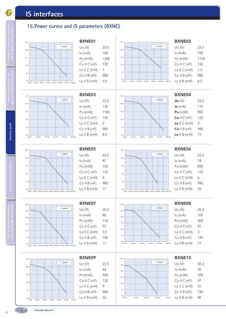
15. Power curves and IS parameters (BXNE)
BXNE01Uo (V): 23.5
Io (mA): 160
Po (mW): 1300
Co II C (nF): 132
Lo II C (mH): 1
Co II B (nF): 980
Lo II B (mH): 5.5
BXNE02Uo (V): 23.5
Io (mA): 150
Po (mW): 1150
Co II C (nF): 132
Lo II C (mH): 1.5
Co II B (nF): 980
Lo II B (mH): 6.5
BXNE03Uo (V): 23.5
Io (mA): 130
Po (mW): 1100
Co II C (nF): 132
Lo II C (mH): 2
Co II B (nF): 980
Lo II B (mH): 8.5
BXNE04Uo (V): 23.5
Io (mA): 110
Po (mW): 900
Co II C (nF): 132
Lo II C (mH): 3
Co II B (nF): 980
Lo II B (mH): 11
BXNE05Uo (V): 23.5
Io (mA): 87
Po (mW): 750
Co II C (nF): 132
Lo II C (mH): 4
Co II B (nF): 980
Lo II B (mH): 17
BXNE06Uo (V): 23.5
Io (mA): 78
Po (mW): 690
Co II C (nF): 132
Lo II C (mH): 6
Co II B (nF): 980
Lo II B (mH): 25
BXNE07Uo (V): 26.3
Io (mA): 80
Po (mW): 710
Co II C (nF): 97
Lo II C (mH): 5.5
Co II B (nF): 740
Lo II B (mH): 17
BXNE08Uo (V): 26.3
Io (mA): 105
Po (mW): 900
Co II C (nF): 97
Lo II C (mH): 3
Co II B (nF): 740
Lo II B (mH): 11
BXNE09Uo (V): 23.5
Io (mA): 64
Po (mW): 590
Co II C (nF): 132
Lo II C (mH): 9
Co II B (nF): 980
Lo II B (mH): 32
BXNE10Uo (V): 26.3
Io (mA): 40
Po (mW): 390
Co II C (nF): 97
Lo II C (mH): 25
Co II B (nF): 740
Lo II B (mH): 80

www.georgin.com43
Tabl
e of
equ
ival
ent
refe
renc
es
acco
rdin
g to
typ
e of
ass
embl
yUs
e of
gal
vani
c in
sula
tion
Sele
ctio
n gu
ide
Gene
ral s
peci
ficat
ions
for
ga
lvan
ic in
sula
tion
inte
rfac
esPr
inci
ple
of a
gal
vani
c in
sula
tion
and
rem
inde
rs c
once
rnin
g I.S
.
IS interfaces
BXNE11Uo (V): 26.3
Io (mA): 70
Po (mW): 630
Co II C (nF): 97
Lo II C (mH): 9.5
Co II B (nF): 740
Lo II B (mH): 32
BXNE31Uo (V): 7.2
Io (mA): 185
Po (mW): 620
Co II C (nF): 14500
Lo II C (mH): 0.9
Co II B (nF): 240000
Lo II B (mH): 4
BXNE34Uo (V): 13
Io (mA): 185
Po (mW): 1250
Co II C (nF): 1000
Lo II C (mH): 0.9
Co II B (nF): 6200
Lo II B (mH): 4
BXNE36Uo (V): 13.1
Io (mA): 142
Po (mW): 600
Co II C (nF): 970
Lo II C (mH): 3
Co II B (nF): 6000
Lo II B (mH): 10
BXNE37Uo (V): 16.1
Io (mA): 270
Po (mW): 2150
Co II C (nF): 451
Lo II C (mH): 0.9
Co II B (nF): 2690
Lo II B (mH): 3
BXNE41Uo (V): 19.5
Io (mA): 170
Po (mW): 1640
Co II C (nF): 240
Lo II C (mH): 0.1
Co II B (nF): 1490
Lo II B (mH): 0.4
BXNE42Uo (V): 27.9
Io (mA): 76
Po (mW): 496
Co II C (nF): 84
Lo II C (mH): 5
Co II B (nF): 654
Lo II B (mH): 19
BXNE49Uo (V): 24.1
Io (mA): 87
Po (mW): 496
Co II C (nF): 124
Lo II C (mH): 5
Co II B (nF): 920
Lo II B (mH): 19
BXNE50Uo (V): 27.4
Io (mA): 112
Po (mW): 737
Co II C (nF): 87
Lo II C (mH): 2.5
Co II B (nF): 677
Lo II B (mH): 10
BXNE61Uo (V): 15
Io (mA): 272
Po (mW): 7473
Co II C (nF): ---
Lo II C (mH): ---
Co II B (nF): 3550
Lo II B (mH): 0.05
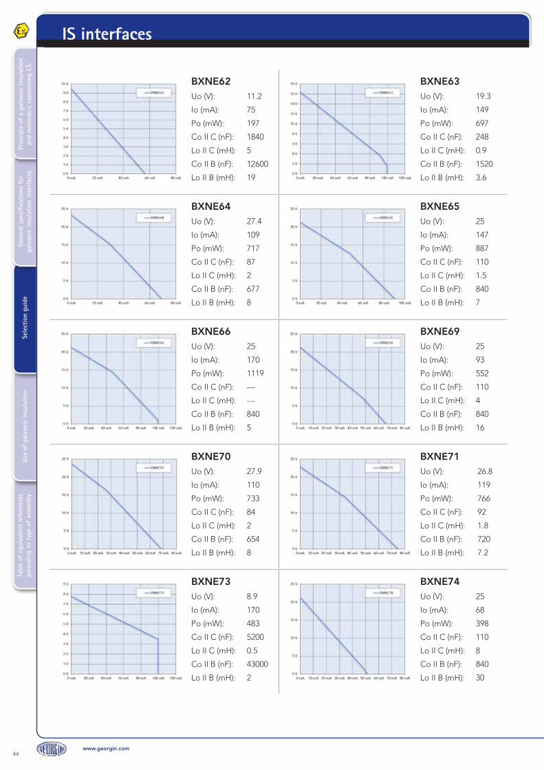
44www.georgin.com
Tabl
e of
equ
ival
ent
refe
renc
es
acco
rdin
g to
typ
e of
ass
embl
yUs
e of
gal
vani
c in
sula
tion
Sele
ctio
n gu
ide
Gene
ral s
peci
ficat
ions
for
ga
lvan
ic in
sula
tion
inte
rfac
esPr
inci
ple
of a
gal
vani
c in
sula
tion
and
rem
inde
rs c
once
rnin
g I.S
.IS interfaces
BXNE62Uo (V): 11.2
Io (mA): 75
Po (mW): 197
Co II C (nF): 1840
Lo II C (mH): 5
Co II B (nF): 12600
Lo II B (mH): 19
BXNE63Uo (V): 19.3
Io (mA): 149
Po (mW): 697
Co II C (nF): 248
Lo II C (mH): 0.9
Co II B (nF): 1520
Lo II B (mH): 3.6
BXNE64Uo (V): 27.4
Io (mA): 109
Po (mW): 717
Co II C (nF): 87
Lo II C (mH): 2
Co II B (nF): 677
Lo II B (mH): 8
BXNE65Uo (V): 25
Io (mA): 147
Po (mW): 887
Co II C (nF): 110
Lo II C (mH): 1.5
Co II B (nF): 840
Lo II B (mH): 7
BXNE66Uo (V): 25
Io (mA): 170
Po (mW): 1119
Co II C (nF): ---
Lo II C (mH): ---
Co II B (nF): 840
Lo II B (mH): 5
BXNE69Uo (V): 25
Io (mA): 93
Po (mW): 552
Co II C (nF): 110
Lo II C (mH): 4
Co II B (nF): 840
Lo II B (mH): 16
BXNE70Uo (V): 27.9
Io (mA): 110
Po (mW): 733
Co II C (nF): 84
Lo II C (mH): 2
Co II B (nF): 654
Lo II B (mH): 8
BXNE71Uo (V): 26.8
Io (mA): 119
Po (mW): 766
Co II C (nF): 92
Lo II C (mH): 1.8
Co II B (nF): 720
Lo II B (mH): 7.2
BXNE73Uo (V): 8.9
Io (mA): 170
Po (mW): 483
Co II C (nF): 5200
Lo II C (mH): 0.5
Co II B (nF): 43000
Lo II B (mH): 2
BXNE74Uo (V): 25
Io (mA): 68
Po (mW): 398
Co II C (nF): 110
Lo II C (mH): 8
Co II B (nF): 840
Lo II B (mH): 30

www.georgin.com45
Tabl
e of
equ
ival
ent
refe
renc
es
acco
rdin
g to
typ
e of
ass
embl
yUs
e of
gal
vani
c in
sula
tion
Sele
ctio
n gu
ide
Gene
ral s
peci
ficat
ions
for
ga
lvan
ic in
sula
tion
inte
rfac
esPr
inci
ple
of a
gal
vani
c in
sula
tion
and
rem
inde
rs c
once
rnin
g I.S
.
IS interfaces
In this example, the intrinsic safety solenoid valve has an internal resistance R of 100Ω.And the current I required for the solenoid valve to operate correctly is 100 mA.
Calculation of voltage U required for the solenoid valve to operate:
U = R x I
U(V) = 100Ω x 0.1 A
U = 10 V
Therefore, using the power curve below we must verify that the BXNE76 is suitable for this application:
The BXNE must be capable of supplying 10 V at 100 mA. The point must therefore be located inside the curve.
Intrinsic safety parameters:
BXNE76
Uo (V): 15Io (mA): 272Po (mW): 3375Co II C (nF): 580Lo II C (mH): 0.3Co II B (nF): 3550Lo II B (mH): 3
The solenoid valve must also be compatible with the power supply in terms of intrinsic safety.
See "Notions of intrinsic safety" chapter.
16. Example of BXNE selection

46www.georgin.com
Tabl
e of
equ
ival
ent
refe
renc
es
acco
rdin
g to
typ
e of
ass
embl
yUs
e of
gal
vani
c in
sula
tion
Sele
ctio
n gu
ide
Gene
ral s
peci
ficat
ions
for
ga
lvan
ic in
sula
tion
inte
rfac
esPr
inci
ple
of a
gal
vani
c in
sula
tion
and
rem
inde
rs c
once
rnin
g I.S
.IS interfaces
Ref.Description (see technical data sheet for further information) IS parameters
ATEX marking
RD
N21
0W
The RDN210W is an intrinsically safe, galvanic insulated digital signal separator.This device does not have an external power supply.The opto-isolator output transistors (H+J-) or (L+M-) are controlled by an input voltage (E+F-) for channel 1 and (C+D-) for channel 2.
Type ModelNumber of channels
Options Power supply
RDN 210Opto-isolator
IS input / NIS outputW
2 channels
00Cage clamp
terminals3 24 V DC
B0 Screw terminals 7 12 V DC
8 5 V DC
Red LED for each channel indicating if the output transistor is conductive or closed.
Maximum current on intrinsic safety circuit:100 mA
Marking:II(1)G [Ex ia] IICII(1)D [Ex iaD] IICCertificate: 02ATEX6104X
RD
N21
0V
The RDN210V is an intrinsically safe, galvanic insulated digital signal separator.Identical to the RDN210W, the RDN210V has four channels.
Type ModelNumber of channels
Options Power supply
RDN 210Opto-isolator
IS input / NIS outputV
4 channels
00Cage clamp
terminals3 24 V DC
B0 Screw terminals 7 12 V DC
8 5 V DC
Red LED for each channel indicating if the output transistor is conductive or closed.
Maximum current on intrinsic safety circuit:100 mA
Marking:II(1)G [Ex ia] IICII(1)D [Ex iaD] IICCertificate: 02ATEX6104X
17. Digital inputs - opto-isolator output signal isolator

www.georgin.com47
Tabl
e of
equ
ival
ent
refe
renc
es
acco
rdin
g to
typ
e of
ass
embl
yUs
e of
gal
vani
c in
sula
tion
Sele
ctio
n gu
ide
Gene
ral s
peci
ficat
ions
for
ga
lvan
ic in
sula
tion
inte
rfac
esPr
inci
ple
of a
gal
vani
c in
sula
tion
and
rem
inde
rs c
once
rnin
g I.S
.
IS interfaces
Explanatory diagram I/O
2 o
pto
-iso
lato
r ch
anne
ls4
op
to-is
ola
tor
chan
nels

48www.georgin.com
Tabl
e of
equ
ival
ent
refe
renc
es
acco
rdin
g to
typ
e of
ass
embl
yUs
e of
gal
vani
c in
sula
tion
Sele
ctio
n gu
ide
Gene
ral s
peci
ficat
ions
for
ga
lvan
ic in
sula
tion
inte
rfac
esPr
inci
ple
of a
gal
vani
c in
sula
tion
and
rem
inde
rs c
once
rnin
g I.S
.IS interfaces
Ref.Description (see technical data sheet for further information) IS parameters
ATEX marking
RD
N21
1W
The RDN211W is an intrinsically safe, galvanic insulated digital signal separator.This device does not have an external power supply.The output relays (HJ) or (LM) are controlled by an input voltage (E+F-) for channel 1 and (C+D-) for channel 2.
Type ModelNumber of channels
Options Power supply
RDN 211Relay outputs
IS input / NIS outputW
2 channels
00Cage clamp
terminalsNO contact
0 230 V AC
B0Screw terminals
NO contact1 110 V AC
01Cage clamp
terminalsNC contact
3 24 V DC
B1Screw terminals
NC contact4 48 V DC
Red LED for each channel indicating if the output relay is active or not.
Maximum voltage on intrinsic safety circuit:60 V
Marking:II(1)G [Ex ia] IICII(1)D [Ex iaD] IICCertificate: 02ATEX6104X
RD
N21
1V
The RDN211V is an intrinsically safe, galvanic insulated digital signal separator.Identical to the RDN211W, the RDN211V has four channels.
Type ModelNumber of channels
Options Power supply
RDN 211Relay outputs
IS input / NIS outputV
4 channels
00Cage clamp
terminalsNO contact
3 24 V DC
B0Screw terminals
NO contact4 48 V DC
01Cage clamp
terminalsNC contact
B1Screw terminals
NC contact
Red LED for each channel indicating if the output relay is active or not.
Maximum current on intrinsic safety circuit:100 mA
Marking:II(1)G [Ex ia] IICII(1)D [Ex iaD] IICCertificate: 02ATEX6104X
18. Digital outputs - relay output signal isolator
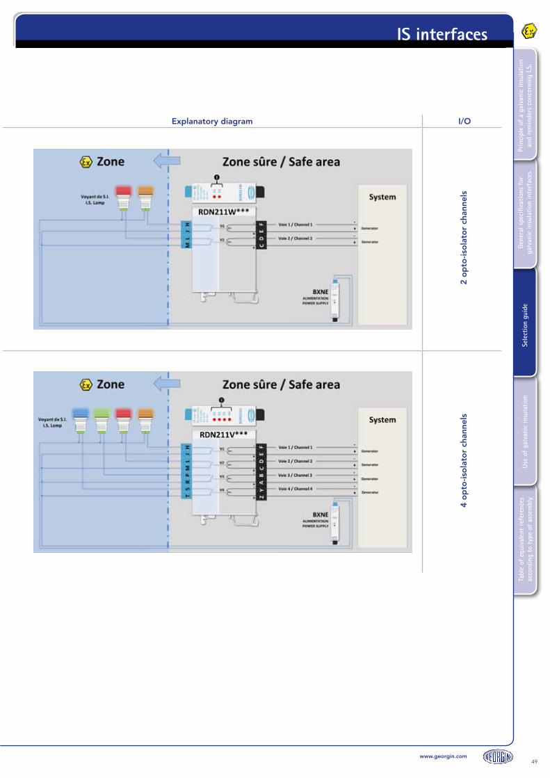
www.georgin.com49
Tabl
e of
equ
ival
ent
refe
renc
es
acco
rdin
g to
typ
e of
ass
embl
yUs
e of
gal
vani
c in
sula
tion
Sele
ctio
n gu
ide
Gene
ral s
peci
ficat
ions
for
ga
lvan
ic in
sula
tion
inte
rfac
esPr
inci
ple
of a
gal
vani
c in
sula
tion
and
rem
inde
rs c
once
rnin
g I.S
.
IS interfaces
Explanatory diagram I/O
2 o
pto
-iso
lato
r ch
anne
ls4
op
to-is
ola
tor
chan
nels
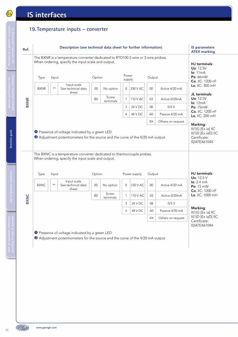
50www.georgin.com
Tabl
e of
equ
ival
ent
refe
renc
es
acco
rdin
g to
typ
e of
ass
embl
yUs
e of
gal
vani
c in
sula
tion
Sele
ctio
n gu
ide
Gene
ral s
peci
ficat
ions
for
ga
lvan
ic in
sula
tion
inte
rfac
esPr
inci
ple
of a
gal
vani
c in
sula
tion
and
rem
inde
rs c
once
rnin
g I.S
.IS interfaces
Ref.Description (see technical data sheet for further information) IS parameters
ATEX marking
BX
NR
The BXNR is a temperature converter dedicated to RTD100 2-wire or 3-wire probes.When ordering, specify the input scale and output.
Type Input OptionPower supply
Output
BXNR **Input scale
See technical data sheet
00 No option 0 230 V AC 00 Active 4/20 mA
B0Screw
terminals1 110 V AC 03 Active 0/20mA
3 24 V DC 08 0/5 V
4 48 V DC A0 Passive 4/20 mA
XX Others on request
Presence of voltage indicated by a green LED Adjustment potentiometers for the source and the curve of the 4/20 mA output
HJ terminals:Uo: 12.5VIo: 11mAPo: 66mWCo, IIC: 1200 nFLo, IIC: 300 mH
JL terminals:Uo: 12.5VIo: 12mAPo: 75mWCo, IIC: 1200 nFLo, IIC: 200 mH
Marking:II(1)G [Ex ia] IICII(1)D [Ex iaD] IICCertificate: 02ATEX6104X
BX
NC
The BXNC is a temperature converter dedicated to thermocouple probes.When ordering, specify the input scale and output.
Type Input Option Power supply Output
BXNC **Input scale
See technical data sheet
00 No option 0 230 V AC 00 Active 4/20 mA
B0Screw
terminals1 110 V AC 03 Active 0/20mA
3 24 V DC 08 0/5 V
4 48 V DC A0 Passive 4/20 mA
XX Others on request
Presence of voltage indicated by a green LED Adjustment potentiometers for the source and the curve of the 4/20 mA output
HJ terminals:Uo: 12.5 VIo: 2.4 mAPo: 15 mWCo, IIC: 1200 nFLo, IIC: 1000 mH
Marking:II(1)G [Ex ia] IICII(1)D [Ex iaD] IICCertificate: 02ATEX6104X
19. Temperature inputs - converter
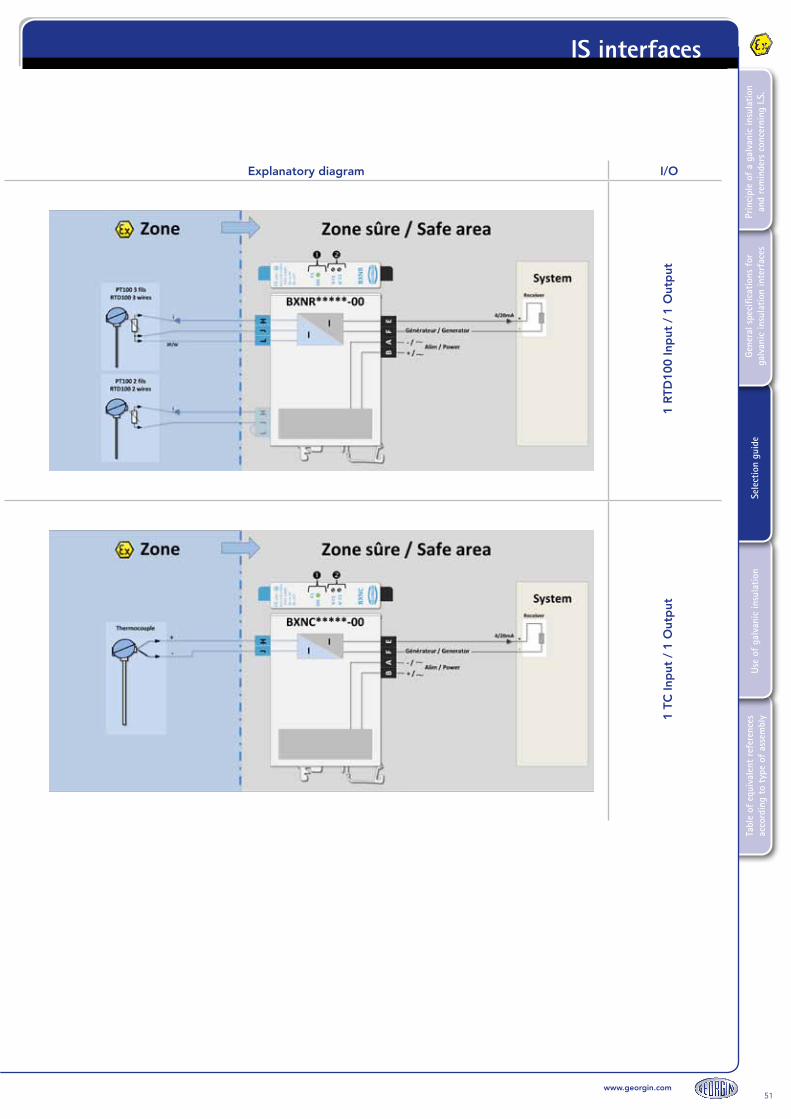
www.georgin.com51
Tabl
e of
equ
ival
ent
refe
renc
es
acco
rdin
g to
typ
e of
ass
embl
yUs
e of
gal
vani
c in
sula
tion
Sele
ctio
n gu
ide
Gene
ral s
peci
ficat
ions
for
ga
lvan
ic in
sula
tion
inte
rfac
esPr
inci
ple
of a
gal
vani
c in
sula
tion
and
rem
inde
rs c
once
rnin
g I.S
.
IS interfaces
Explanatory diagram I/O
1 R
TD10
0 In
put
/ 1
Out
put
1 TC
Inp
ut /
1 O
utp
ut

52www.georgin.com
Tabl
e of
equ
ival
ent
refe
renc
es
acco
rdin
g to
typ
e of
ass
embl
yUs
e of
gal
vani
c in
sula
tion
Sele
ctio
n gu
ide
Gene
ral s
peci
ficat
ions
for
ga
lvan
ic in
sula
tion
inte
rfac
esPr
inci
ple
of a
gal
vani
c in
sula
tion
and
rem
inde
rs c
once
rnin
g I.S
.IS interfaces
Ref.Description (see technical data sheet for further information) IS parameters
ATEX marking
BX
NP
The BXNP is a converter for potentiometers.When ordering, specify the input scale and output.
Type Input Option Power supply Output
BXNP
**
0-1 KΩ to 0-50 KΩ4 mA adjustable
within 0-30% of the range
20 mA adjustable within 70-100%
of the range
00 No option 0 230 V AC B0 Active 4/20 mA
B0Screw
terminals1 110 V AC
3 24 V DC
** Other on request 4 48 V DC
Presence of voltage indicated by a green LED Adjustment potentiometers for the source and the curve of the 4/20 mA output
HJ terminals:Uo: 12.5 VIo: 80 mAPo: 600 mWCo, IIC: 1200 nFLo, IIC: 5 mH
JL terminals:Uo: 12.5 VIo: 2.4 mAPo: 15 mWCo, IIC: 1200 nFLo, IIC: 1000 mH
Marking:II(1)G [Ex ia] IICII(1)D [Ex iaD] IICCertificate: 02ATEX6104X
BX
NR
V
The BXNRV is used to interface a 2-wire variable resistance.
Type Input Option Power supply Output
BXNC V1
4 mA adjustable between 270 and 330Ω
20 mA adjustable between 850 and 1700Ω
00No
option0
230 V AC
00 Active 4/20 mA
V5
4 mA adjustable between 3900 and 5500Ω
20 mA adjustable between 8200 and 11200Ω
B0Screw
terminals1
110 V AC
03 Active 0/20mA
V6
4 mA adjustable between 0 and 750Ω
20 mA adjustable between 6000 and 7500Ω
3 24 V DC 08 0/5 V
** Other on request 4 48 V DC A0Passive 4/20
mA
XXOthers on
request
Presence of voltage indicated by a green LED Adjustment potentiometers for the source and the curve of the 4/20 mA output
HJ terminals:Uo: 12.5 VIo: 11 mAPo: 66 mWCo, IIC: 1200 nFLo, IIC: 300 mH
Marking:II(1)G [Ex ia] IICII(1)D [Ex iaD] IICCertificate: 02ATEX6104X
20. Potentiometer inputs - resistance-converter
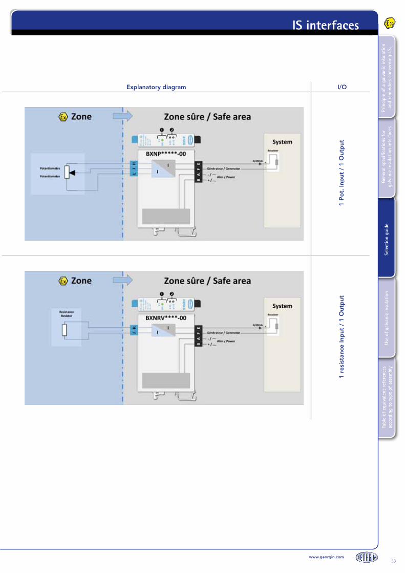
www.georgin.com53
Tabl
e of
equ
ival
ent
refe
renc
es
acco
rdin
g to
typ
e of
ass
embl
yUs
e of
gal
vani
c in
sula
tion
Sele
ctio
n gu
ide
Gene
ral s
peci
ficat
ions
for
ga
lvan
ic in
sula
tion
inte
rfac
esPr
inci
ple
of a
gal
vani
c in
sula
tion
and
rem
inde
rs c
once
rnin
g I.S
.
IS interfaces
Explanatory diagram I/O
1 P
ot.
Inp
ut /
1 O
utp
ut1
resi
stan
ce In
put
/ 1
Out
put

54www.georgin.com
Tabl
e of
equ
ival
ent
refe
renc
es
acco
rdin
g to
typ
e of
ass
embl
yUs
e of
gal
vani
c in
sula
tion
Sele
ctio
n gu
ide
Gene
ral s
peci
ficat
ions
for
ga
lvan
ic in
sula
tion
inte
rfac
esPr
inci
ple
of a
gal
vani
c in
sula
tion
and
rem
inde
rs c
once
rnin
g I.S
.IS interfaces
21. Universal inputs - threshold relays
Ref. Description (see technical data sheet for further information)IS parametersATEX marking
BP
X
The BPX is a programmable, galvanic-insulated converter with a universal input.Can be configured via PC using the ProgressX manager software and anRS232 serial cable.
Type ModelOptional terminal block
Power supply Input Output
BPX 0 NSI / NIS 00 Cage clamp E 98 to 255
V AC10 1 input 10 1 Output 4/20 mA
1 SI / IS B0 Screw 2 21 to 53 V
DC11 1 input + HART 1A
1 x 4/20 mA output2 relays (inverters)
2D* 2 x 4/20 mA outputs
2 relays (Contact, NO)
2G* 2 x 4/20 mA outputs
2 relays (Contact, NC)
0C 2 relays
(Contact, NO)
0F 2 relays
(Contact, NC)
0B 4 relays
(Contact, NO)
0E 4 relays
(Contact, NC)
TransmitterZ-X terminals:Uo: 27.9 VIo: 78.2 mAPo: 545.47 mWCo, IIC: 0.084 µFLo, IIC: 2.8 mH
Current XT terminals:Uo: 0.057 VIo: 2.82 mAPo: 0.04 mWCo, IIC: 1000 µFLo, IIC: 100 mH
mV-V-TC-RTD100-PotWUSRPT terminalsUo: 7 VIo: 5.64 mAPo: 9.87 mWCo, IIC: 15.70 µFLo, IIC: 100 mH
Marking:II(1)G [Ex ia] IICII(1)D [Ex iaD] IICCertificate: 02ATEX6104X
Inputs:Current (mA) -2.5 to +23 mAVoltage (mV) -10 to +105 mVVoltage (V) -1 to +10.5 VThermocouple J -210 to +1200 °CThermocouple K -250 to +1372 °CThermocouple B +400 to +1820 °CThermocouple R -50 to +1768 °CThermocouple S -50 to +1768 °CThermocouple T -250 to +400 °CThermocouple E** -270 to +1000 °CThermocouple N -240 to +1300 °CThermocouple W5 -20 to +2320 °C2-wire PT 100 resistance3-wire PT 100 resistance4-wire PT 100 resistance2/3/4-wire sensor +3.5 to +23 mAPotentiometer 0 to 100% of 1 KΩ to 20 KΩ
Presence of voltage indicated by a green LEDMicro-controller operation indicated by flashing green LED.Red LED to indicate activation of the output relays (depending on option selected).
RS232 connection for configuration of BPX via PC Shunt to create Passive output only Indifferently active or passive output

www.georgin.com55
Tabl
e of
equ
ival
ent
refe
renc
es
acco
rdin
g to
typ
e of
ass
embl
yUs
e of
gal
vani
c in
sula
tion
Sele
ctio
n gu
ide
Gene
ral s
peci
ficat
ions
for
ga
lvan
ic in
sula
tion
inte
rfac
esPr
inci
ple
of a
gal
vani
c in
sula
tion
and
rem
inde
rs c
once
rnin
g I.S
.
IS interfaces
Explanatory diagram I/O
1 In
put
/ u
p t
o 2
x 4
/20
mA
out
put
sup
to
4 r
elay
out
put
s
Ref. Description (see technical data sheet for further information)IS parametersATEX marking
BP
X
The BPX is a programmable, galvanic-insulated converter with a universal input.Can be configured via PC using the ProgressX manager software and anRS232 serial cable.
Type ModelOptional terminal block
Power supply Input Output
BPX 0 NSI / NIS 00 Cage clamp E 98 to 255
V AC10 1 input 10 1 Output 4/20 mA
1 SI / IS B0 Screw 2 21 to 53 V
DC11 1 input + HART 1A
1 x 4/20 mA output2 relays (inverters)
2D* 2 x 4/20 mA outputs
2 relays (Contact, NO)
2G* 2 x 4/20 mA outputs
2 relays (Contact, NC)
0C 2 relays
(Contact, NO)
0F 2 relays
(Contact, NC)
0B 4 relays
(Contact, NO)
0E 4 relays
(Contact, NC)
TransmitterZ-X terminals:Uo: 27.9 VIo: 78.2 mAPo: 545.47 mWCo, IIC: 0.084 µFLo, IIC: 2.8 mH
Current XT terminals:Uo: 0.057 VIo: 2.82 mAPo: 0.04 mWCo, IIC: 1000 µFLo, IIC: 100 mH
mV-V-TC-RTD100-PotWUSRPT terminalsUo: 7 VIo: 5.64 mAPo: 9.87 mWCo, IIC: 15.70 µFLo, IIC: 100 mH
Marking:II(1)G [Ex ia] IICII(1)D [Ex iaD] IICCertificate: 02ATEX6104X
Inputs:Current (mA) -2.5 to +23 mAVoltage (mV) -10 to +105 mVVoltage (V) -1 to +10.5 VThermocouple J -210 to +1200 °CThermocouple K -250 to +1372 °CThermocouple B +400 to +1820 °CThermocouple R -50 to +1768 °CThermocouple S -50 to +1768 °CThermocouple T -250 to +400 °CThermocouple E** -270 to +1000 °CThermocouple N -240 to +1300 °CThermocouple W5 -20 to +2320 °C2-wire PT 100 resistance3-wire PT 100 resistance4-wire PT 100 resistance2/3/4-wire sensor +3.5 to +23 mAPotentiometer 0 to 100% of 1 KΩ to 20 KΩ
Presence of voltage indicated by a green LEDMicro-controller operation indicated by flashing green LED.Red LED to indicate activation of the output relays (depending on option selected).
RS232 connection for configuration of BPX via PC Shunt to create Passive output only Indifferently active or passive output
ProgressX manager software (BPX Configuration)

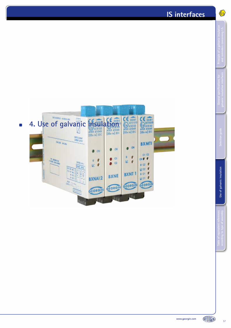
4. Use of galvanic insulation
57www.georgin.com
Tabl
e of
equ
ival
ent
refe
renc
es
acco
rdin
g to
typ
e of
ass
embl
yUs
e of
gal
vani
c in
sula
tion
Sele
ctio
n gu
ide
Gene
ral s
peci
ficat
ions
for
ga
lvan
ic in
sula
tion
inte
rfac
esPr
inci
ple
of a
gal
vani
c in
sula
tion
and
rem
inde
rs c
once
rnin
g I.S
.
IS interfaces

1. Connection• Standard: plug-in cage clamp terminals (max. capacity 2.5 mm²)A flat head screwdriver (0.6 x 3.5 mm) is recommended to open the cage clamp terminal.• Optional: plug-in screw terminals (max. capacity 2.5 mm²)
2. InstallationThe equipment is intended for association in accordance with intrinsic safety; the installation must be in compliance with standard EN 60079-14, in particular paragraph 12.
3. Fixing and mounting The equipment is intended for installation on an EN 50022 rail attached horizontally on a vertical plane, in order to respect the direction of natural convection. Do not obstruct the air vents. Use a screwdriver to insert and remove the equipment as indicated.
4. LocationThe equipment must be installed in a non-explosive atmosphere, in a sound environment free of condensation and corrosive or conductive dust.Intrinsic safety is ensured in the operating temperature range specified in paragraph 1.6. However you should remember that the service life of electronic equipment is reduced by half when its temperature is increased by 10°C. You should therefore install the equipment in suitably ventilated equipment rooms, avoid the proximity of elements that may heat the equipment by radiation or which are likely to generate electromagnetic radiation greater than 10V/m.
5. Electrical connection Electrical connections must be made when the equipment is DE-ENERGIZED, using wires with a maximum diameter of 2.5 mm².For connections, refer to the wiring diagram.
6. Mechanical properties The intrinsic safety terminals must only be connected to intrinsic safety equipment or equipment which is in compliance with paragraph 5.7 of standard EN 60079-11.Moreover, the association of equipment and the connection cable must be compatible in terms of intrinsic safety.
Please ensure you read all the instructions in the individual product manual and only start the installation work when you have understood everything.
This manual is supplied with each product. It is also available on our website:www.georgin.com
These equipment items may receive hazardous voltages on their terminals.If you do not follow the instructions correctly, you may expose yourself and others to serious injury as well as damage to equipment.Before starting your installation, ensure that the model and power supply are suited to your purpose. This equipment should only be connected in accordance with applicable regulations by qualified personnel.
58www.georgin.com
Tabl
e of
equ
ival
ent
refe
renc
es
acco
rdin
g to
typ
e of
ass
embl
yUs
e of
gal
vani
c in
sula
tion
Sele
ctio
n gu
ide
Gene
ral s
peci
ficat
ions
for
ga
lvan
ic in
sula
tion
inte
rfac
esPr
inci
ple
of a
gal
vani
c in
sula
tion
and
rem
inde
rs c
once
rnin
g I.S
.IS interfaces

7. Cable pathThe properties of cables and their routing from the ATEX zone (I.S. cables) must comply with the recommendations set out in paragraphs 6.1, 6.2.1 and 6.3 of standard EN 600079-11.Full precautions must be taken to prevent electromagnetic disturbance with other cables that may generate dangerous voltages or currents.The I.S. cables must be clamped in order to prevent random contact with other cables in the event the terminal is shorn.
8. Adjustments and configuration See technical data sheet or instructions for use.
9. MaintenancePrecautions to take during maintenanceDismounting must be carried out DE-ENERGIZED.In the event you suspect a failure or permanent fault, return the equipment to our services or representatives, who are the only maintenance providers certified to perform expert assessments or repairs.
10. Dismounting
59www.georgin.com
Tabl
e of
equ
ival
ent
refe
renc
es
acco
rdin
g to
typ
e of
ass
embl
yUs
e of
gal
vani
c in
sula
tion
Sele
ctio
n gu
ide
Gene
ral s
peci
ficat
ions
for
ga
lvan
ic in
sula
tion
inte
rfac
esPr
inci
ple
of a
gal
vani
c in
sula
tion
and
rem
inde
rs c
once
rnin
g I.S
.
IS interfaces


61www.georgin.com
Tabl
e of
equ
ival
ent
refe
renc
es
acco
rdin
g to
typ
e of
ass
embl
yUs
e of
gal
vani
c in
sula
tion
Sele
ctio
n gu
ide
Gene
ral s
peci
ficat
ions
for
ga
lvan
ic in
sula
tion
inte
rfac
esPr
inci
ple
of a
gal
vani
c in
sula
tion
and
rem
inde
rs c
once
rnin
g I.S
.
IS interfaces
5. Table of equivalent references according to type of assembly

1. Assembly methods
Not covered in this guide. Our equipment features other assembly methods. See technical data sheet for further information.
I/OMounting
DIN rail I.S.(Intrinsic Safety)
Equivalent backplane
mounting I.S.(Intrinsic Safety)
Equivalent board mounting
I.S.(Intrinsic Safety)
Equivalent to mounting on DIN
rail N.I.S(Non-Intrinsic Safety)
AI BXNT6 - - BVNT
AI BXMT - - BVMT
AI BXLT - - BVLT
AI BXNTI6 BETI LV0I BVLTI
AI BXMTI - - BVMT
AI BXLTI - - BVMTI
AI BXNT1 BET LV0 BVNS
AI - AO BXNI BEI DIC BVNI
DI RDN110 BED110 CRN -
DI RDN211 BED211 CRN -
DI RDN112 BED112 CRN -
DI RDN100 BED100 - -
DI RDN210 BED210 - -
DI RDN102 BED102 - -
DI RDN310 / 410 BED310 / 410 - -
DI RDN213 V/W - - -
AO BXNA BEA LW0 BVNA
AO BXNAI BEAI - BVNAI
DO BXNE BEE CASI -
DO RDN210 V/W - - -
DO RDN211V/W - - -
TI BXNR BER LXR BVNR
TI BXNC BEC LXC BVNC
PI BXNP BEP LXP BVNP
RI BXNRV - - BVNRV
UI BPX1 - LPX - CPX BPX0
62www.georgin.com
Tabl
e of
equ
ival
ent
refe
renc
es
acco
rdin
g to
typ
e of
ass
embl
yUs
e of
gal
vani
c in
sula
tion
Sele
ctio
n gu
ide
Gene
ral s
peci
ficat
ions
for
ga
lvan
ic in
sula
tion
inte
rfac
esPr
inci
ple
of a
gal
vani
c in
sula
tion
and
rem
inde
rs c
once
rnin
g I.S
.IS interfaces


fc-in
terf
aces
-en-
20-0
3-20
13Su
bje
ct t
o m
od
ifica
tions
due
to
tec
hnic
al a
dva
nces
www.georgin.com
Régulateurs GEORGIN
France14-16, rue Pierre Sémard - BP 107 - 92323 CHATILLON Cedex France
Tel: +33 (0)1 46 12 60 00 - Fax: +33 (0)1 47 35 93 98 - Email: [email protected]
BelgiumTemselaan 5 - 1st floor - 1853 STROMBEEK-BEVER
Tel: 02 735 54 75 - Fax: 02 735 16 79 - Email: [email protected]
“Imagined, designed and made in France”