Embed Size (px)
Citation preview
Network Analysis and Synthesis
Chapter 7Filter types, specifications
7.1 Introduction
• Filters can be considered as frequency selective networks.
• A filter is required to separate unwanted signal from a mixture of unwanted and wanted signals.
• The transfer characteristic of a filter is so shaped that the ratio of unwanted to wanted signal at the output of the filter is minimized.
• Filter transfer characteristics are usually given interims of filter specifications.
• The filter specifications are then given in terms of cut-off frequencies (pass band frequencies) and stop-band frequency.
• Pass-band:-the frequency band of wanted signals.• Stop-band:- the frequency band of unwanted
signals.• Cut-off frequency:- The frequency associated with
the boundary between stop band and an adjacent pass-band. It is the frequency at which the output is 0.707 times the maximum value in the pass band.
7.2 Types of filters
• According to their pass band and stop band frequencies, filters are categorized as:– Low pass filters– Band pass filters– High pass filters– Band reject filters
• An ideal filter should pass the wanted signals with no attenuation and provide infinite attenuation for the unwanted signals.
• Electric filters are ubiquitous and it is difficult to conceive a modern electronic device or system which does not employ and electric filter.
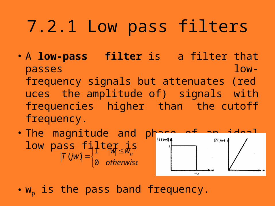
7.2.1 Low pass filters
• A low-pass filter is a filter that passes low-frequency signals but attenuates (reduces the amplitude of) signals with frequencies higher than the cutoff frequency.
• The magnitude and phase of an ideal low pass filter is
• wp is the pass band frequency.
otherwise
wwjwT p
0
1)(
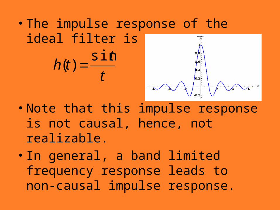
• The impulse response of the ideal filter is
• Note that this impulse response is not causal, hence, not realizable.
• In general, a band limited frequency response leads to non-causal impulse response.
t
tth
sin)(
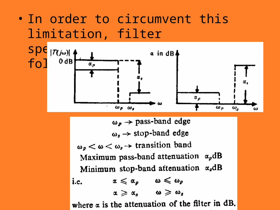
• In order to circumvent this limitation, filter specifications are given as follows
• In words:–The attenuation should be less than αp
in the pass band.–The attenuation should be greater than
αs in the stop band.–The attenuation can be anything in the
transition band (the frequency band between the pass band and the stop band).
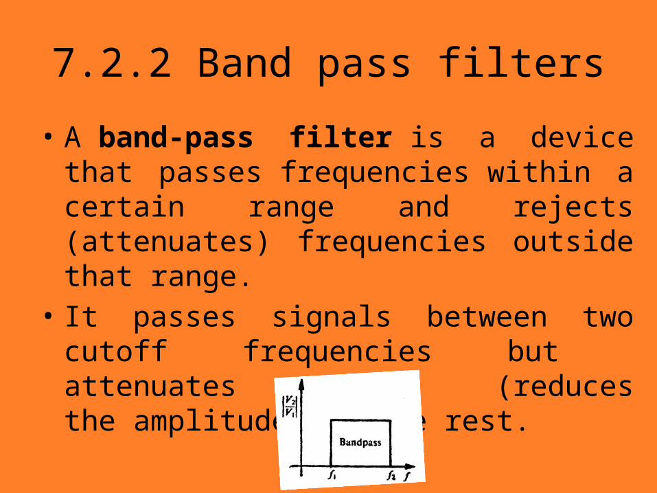
7.2.2 Band pass filters
• A band-pass filter is a device that passes frequencies within a certain range and rejects (attenuates) frequencies outside that range.
• It passes signals between two cutoff frequencies but attenuates (reduces the amplitude of) the rest.
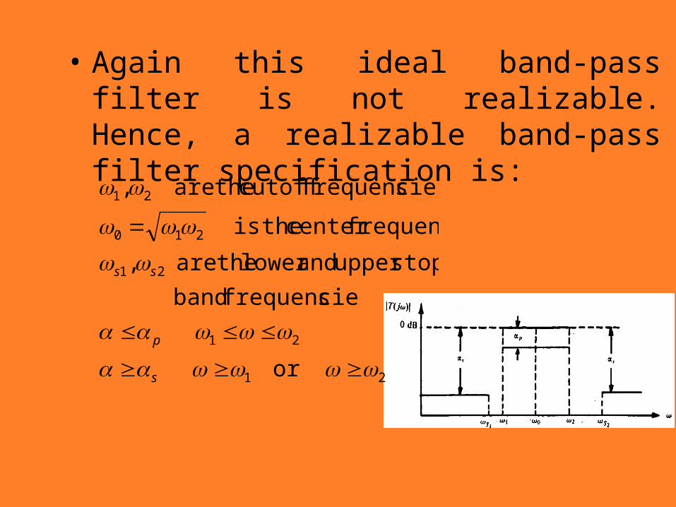
• Again this ideal band-pass filter is not realizable. Hence, a realizable band-pass filter specification is:
21
21
21
210
21
or
sfrequencie band
stopupper andlower theare ,
frequencycenter theis
sfrequencie cutoff theare ,
s
p
ss
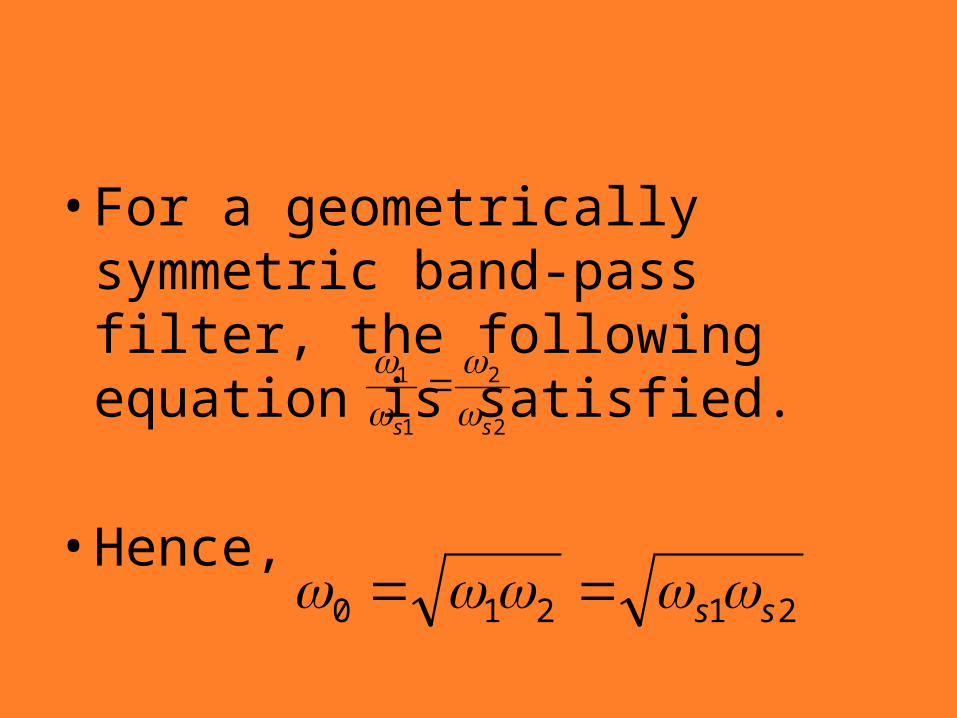
• For a geometrically symmetric band-pass filter, the following equation is satisfied.
• Hence, 2
2
1
1
ss
21210 ss
7.2.3 High pass filters
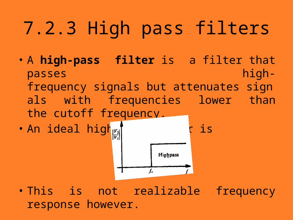
• A high-pass filter is a filter that passes high-frequency signals but attenuates signals with frequencies lower than the cutoff frequency.
• An ideal high-pass filter is
• This is not realizable frequency response however.
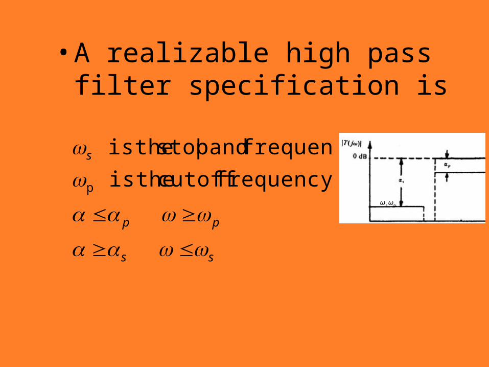
• A realizable high pass filter specification is
ss
pp
s
frequency cutoff theis
frequencie band stop theis
pωpωs
7.2.4 Band reject filters
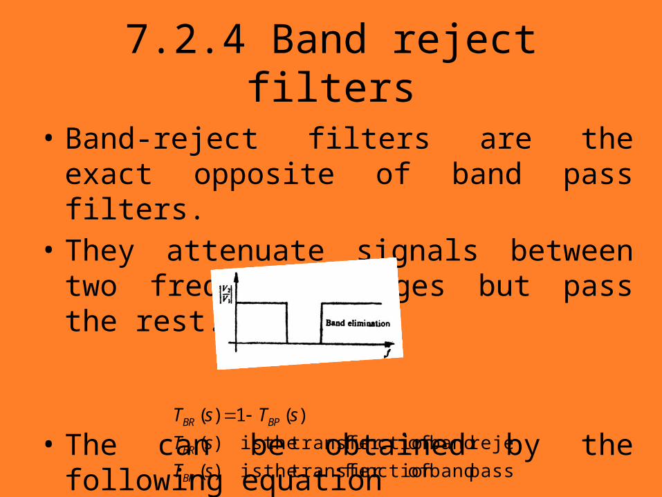
• Band-reject filters are the exact opposite of band pass filters.
• They attenuate signals between two frequency ranges but pass the rest.
• The can be obtained by the following equation
pass band offunction transfer theis )(
reject band offunction transfer theis )(
)(1)(
sT
sT
sTsT
BP
BR
BPBR
7.3 Frequency transformation
• Most of the widely used filter synthesis methods (will be discussed in next chapter) are for low pass filters only.
• So how do we synthesize band-pass, high-pass and band-reject filters?
We use frequency transformation methods.
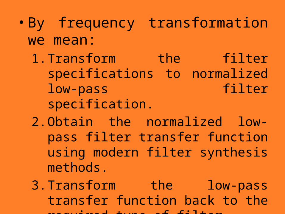
• By frequency transformation we mean:1. Transform the filter specifications to
normalized low-pass filter specification.2. Obtain the normalized low-pass filter
transfer function using modern filter synthesis methods.
3. Transform the low-pass transfer function back to the required type of filter.
4. Synthesize the filter.• Steps 3 and 4 can be exchanged.
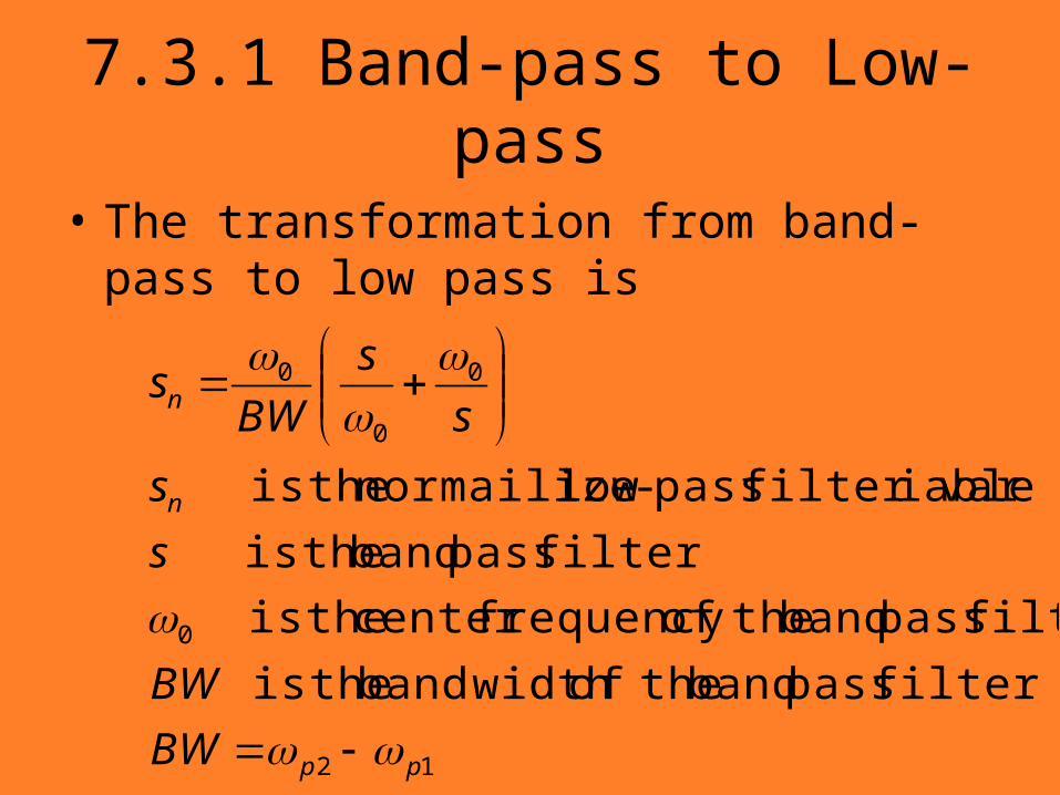
7.3.1 Band-pass to Low-pass
• The transformation from band-pass to low pass is
12
0
0
0
0
filter pass band theof width band theis
filter pass band theoffrequency center theis
filter pass band theis
iablefilter var pass-low normailize theis
pp
n
n
BW
BW
s
s
s
s
BWs
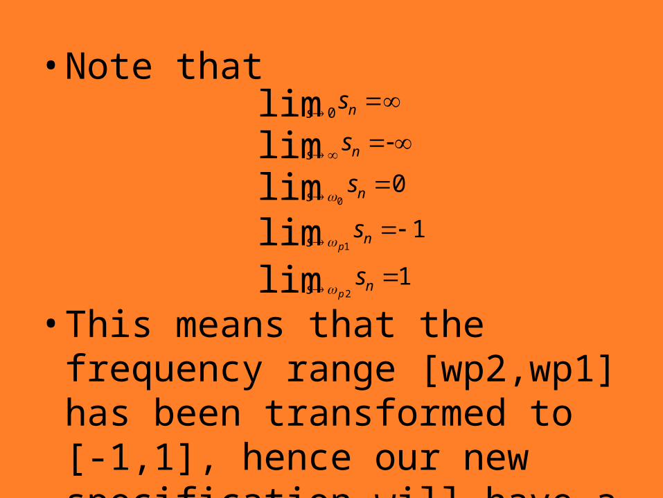
• Note that
• This means that the frequency range [wp2,wp1] has been transformed to [-1,1], hence our new specification will have a low pass form.
1
1
0
limlimlimlimlim
2
1
0
0
ns
ns
ns
ns
ns
s
s
s
s
s
p
p
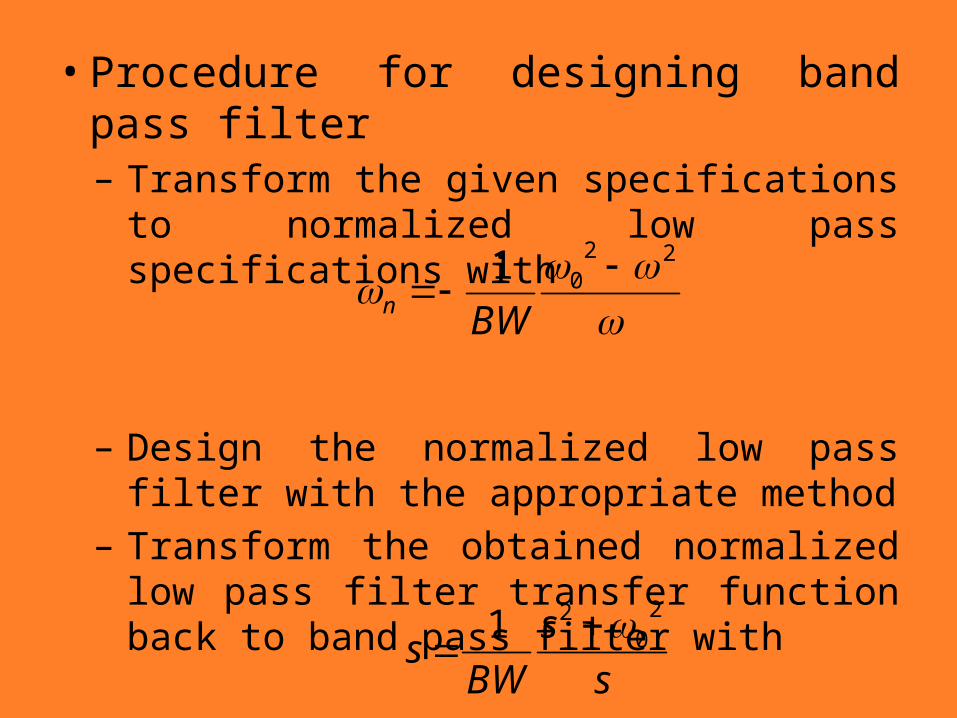
• Procedure for designing band pass filter– Transform the given specifications to
normalized low pass specifications with
–Design the normalized low pass filter with the appropriate method– Transform the obtained normalized low
pass filter transfer function back to band pass filter with
2201
BWn
s
s
BWs
20
21
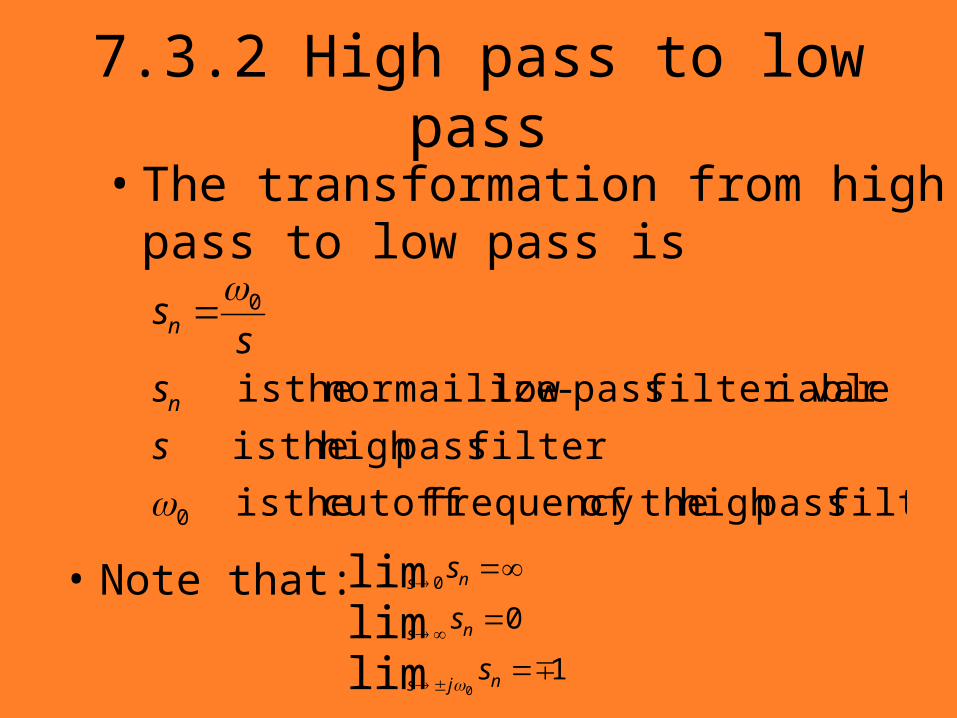
7.3.2 High pass to low pass• The transformation from high pass to low
pass is
filter passhigh theoffrequency cutoff theis
filter passhigh theis
iablefilter var pass-low normailize theis
0
0
s
ss
s
n
n
• Note that:
1
0
limlimlim
0
0
njs
ns
ns
s
s
s
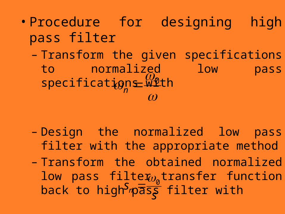
• Procedure for designing high pass filter– Transform the given specifications to
normalized low pass specifications with
–Design the normalized low pass filter with the appropriate method– Transform the obtained normalized low pass
filter transfer function back to high pass filter with
0n
ssn
0
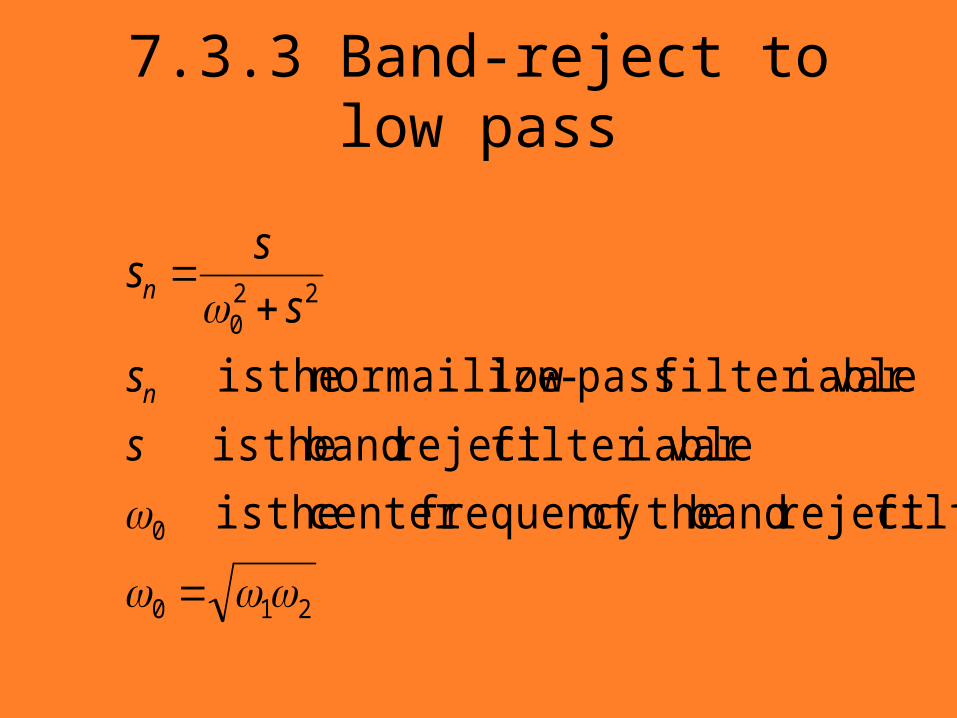
7.3.3 Band-reject to low pass
210
0
220
filterreject band theoffrequency center theis
iablefilter varreject band theis
iablefilter var pass-low normailize theis
s
s
s
ss
n
n
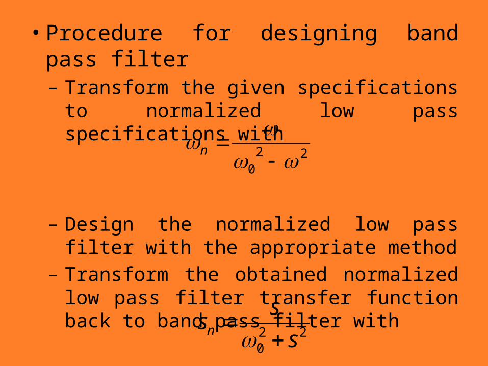
• Procedure for designing band pass filter– Transform the given specifications to
normalized low pass specifications with
–Design the normalized low pass filter with the appropriate method– Transform the obtained normalized low
pass filter transfer function back to band pass filter with
220 s
ssn
220
n
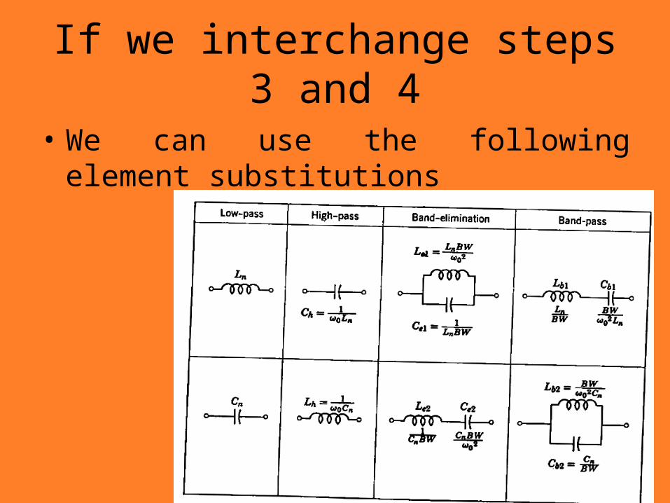
If we interchange steps 3 and 4
• We can use the following element substitutions