Embed Size (px)
Citation preview
1
C O V E R S H E E T
N E T W O R K - C E N T R I C A P P L I C A T I O N S
A N D T A C T I C A L N E T W O R K S
TRACK ASSIGNED – unknown Mr. Timothy Krout Vice President Engineering, CenGen Inc. 5356 High Tor Hill Columbia, MD 21045 [email protected] (410) 715 1300 Mr. Steven Durbano Sr. Network Engineer, CenGen Inc. 5356 High Tor Hill Columbia, MD 21045 [email protected] (410) 715 1300 Ms. Ruth Shearer Enabling Capability Manager, Littoral Combat & Power Projection Future Naval Capability Office of Naval Research Ballston Center Tower 3, Suite 623 Arlington, VA 22217 [email protected] (703) 696-1358 Submitted to: 8th International Command and Control Research and Technology Symposium, c/o Bonnie Mottram, Evidence Based Research Inc. 1595 Spring Hill Road, Suite 250 Vienna, VA 22182-2216 [email protected]

2
N E T W O R K - C E N T R I C A P P L I C A T I O N S
A N D T A C T I C A L N E T W O R K S
Mr. Timothy Krout Vice President Engineering, CenGen Inc. 5356 High Tor Hill Columbia, MD 21045 [email protected] (410) 715 1300 Mr. Steven Durbano Sr. Network Engineer, CenGen Inc. 5356 High Tor Hill Columbia, MD 21045 [email protected] (410) 715 1300 Ms. Ruth Shearer Enabling Capability Manager, Littoral Combat & Power Projection Future Naval Capability Office of Naval Research Ballston Center Tower 3, Suite 623 Arlington, VA 22217 [email protected] (703) 696-1358
3
Abstract The focus of the paper is required interaction of Command and Control (C2) applications and the tactical network on which they effectively operate. Command and control applications will always require communications capabilities. There are numerous examples of command and control applications that have been developed without adequate attention to the realities of tactical networks. The results of various tests and experimental efforts where tactical networks were characterized in operationally realistic environments are provided within the discussion. Connectivity, latency, and throughput related data is presented to make a case that tactical communications cannot now, and will never likely, achieve wired communications capabilities. In fact, these environments perform significantly below the levels achievable on a wired network. As such, C2 applications must accommodate the anticipated performance characteristics associated with tactical networks in order to meet the required C2 capabilities, current and emerging, of the war fighters. Since these applications are dependant on the tactical communications, the development process must address the integration of these applications into the total operational architecture. Integration implies not only the sharing of common resources but also the resolution of compatibility issues, such as those discussed in this paper. Integration is not easily or inexpensively achieved after the fact, therefore must be addressed early in the application design process. Performance characteristics for the networks tested in the referenced efforts are provided as extrapolations to the anticipated tactical networks of the future. The relevant C2 test bed configurations are also discussed enabling C2 application development in wired environments, while simulating reasonable tactical network connectivity. The anticipated future enhancement of military Command, Control, Communications, Computers and Intelligence (C4I) capabilities necessitate the intelligent amalgamation of new C2 applications and improved communications services. The development of the C2 applications with relevant tactical network connectivity information will significantly improve the applications’ operational performance characteristics.
Introduction “Comms sucks,” has been the mantra for most of the Armed Services for as long as communications has been a component of warfare. In the early days of modern warfare, voice communications was the primary means of communications. Limited or non-existent communications were often relatively easy to detect, although often not easy to remedy. In the more modern era where digital communication and advanced command and control applications are executed over a digital network, the accuracy of the information presented as part of a status or situational update is often unclear to the war fighter. In many cases, this information is inaccurate due to technical challenges or physical limitations to the communications information systems. The authors of this paper are primarily communicators who have witnessed a disturbing trend in recent years by command and control developers who develop applications based, at least implicitly, on two erroneous and somewhat dangerous assumptions:
1. At some point tactical wireless networks would be nearly ubiquitous in the battlefield.
4
2. At some point tactical wireless network connectivity and/or performance would approach levels of performance comparable to existing wired digital networks.
The authors believe these two assumptions made by many applications developers are short-sighted. While there is likely concurrence on the general implication that a wired network will always exceed wireless networks in basic network capabilities, there are numerous examples of C2 applications which have been developed in a wired environment, without attention to the trade-offs required for operation in a tactical wireless environment. Alternatively, some C2 application development processes attempt to model the network environment to minute detail, thereby resulting in a stove-piped approach where significant resources are spent modeling a network, or even worse a particular radio approach. The application is hen expected to operate on a completely different network or radio. The authors present data that suggest basic network characteristics, namely throughput, packet loss, and latency, are all that are needed to effectively allow application developers to model tactical networks. Physical, Media Access Control (MAC), and network layer details are not necessary. It is not prudent for application developers to address this level of detail in the communications modeling or simulation efforts. As such, developing applications in environments similar to those discussed in this paper will produce C2 applications, or other applications, that are tolerant of emerging tactical networks. In the following sections, guidance and supporting data gathered from a number of Advanced Concept Technology Demonstrations and similar large-scale demonstrations help make the point that tactical wireless network communications will neither be ubiquitous, nor will they ever approach comparable levels of performance to a wired network. A set of guidelines supported by the data is proposed to layout generic performance characterization numbers that application developers can use to build applications that with better performance over the tactical networks envisioned by the future war fighters. The subsequent section provides specific details related to the communications network architecture for three tactical network demonstrations that have been conducted . The first network is based on the Extending the Littoral Battlespace Advanced Concept Demonstration (ELB ACTD ACTD), which was conducted in Southern California in 2001. The second is based on the Defense Advanced Research Project Agency (DARPA)/ARMY Boeing Lead System Integrator (LSI) Future Combat System (FCS) Communications baseline characterization demonstration and test conducted in New Jersey in 2003. The third is based on data collected at Marine Corps Tactical System Support Activity (MCTSSA), Camp Pendleton using a Littoral Combat Future Naval capability (LCFNC) secure wireless Local Area Network (LAN) test bed. This test bed is meant to replicate wireless connectivity in and around a command post. In all these cases, data is provided in the discussion that can enhance the understanding of application developers of the type of wireless communications performance parameters such as throughput, packet loss and latency. The intent of providing this data in the format of these demonstration cases is the generation of the guidance information relevant to the types of networks believed to be typical tactical architectures.
5
This paper concludes with recommendations on how C2 application developers can establish laboratory simulations to provide realistic communications environment in the laboratory environment. There are several commercial software packages and freeware available that allow the creation of a laboratory network, providing reasonable throughput, packet loss and latency limitations. In addition, limitations of other important parameters allow the application developers a reasonably reliable and deterministic environment which to develop applications. The authors have successfully used such environments with other application developers prior to the subsequent field testing to ensure that application performance characteristics are suitable to the end user prior to actual fielding in the demonstration venues.
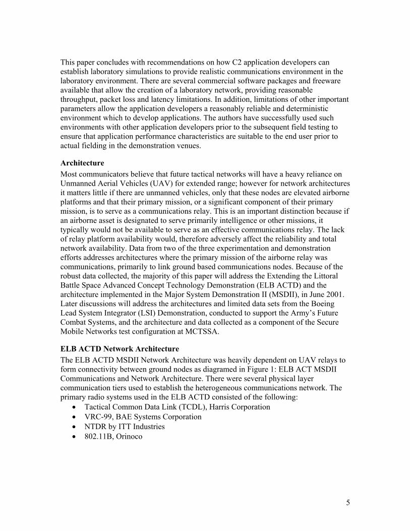
Architecture Most communicators believe that future tactical networks will have a heavy reliance on Unmanned Aerial Vehicles (UAV) for extended range; however for network architectures it matters little if there are unmanned vehicles, only that these nodes are elevated airborne platforms and that their primary mission, or a significant component of their primary mission, is to serve as a communications relay. This is an important distinction because if an airborne asset is designated to serve primarily intelligence or other missions, it typically would not be available to serve as an effective communications relay. The lack of relay platform availability would, therefore adversely affect the reliability and total network availability. Data from two of the three experimentation and demonstration efforts addresses architectures where the primary mission of the airborne relay was communications, primarily to link ground based communications nodes. Because of the robust data collected, the majority of this paper will address the Extending the Littoral Battle Space Advanced Concept Technology Demonstration (ELB ACTD) and the architecture implemented in the Major System Demonstration II (MSDII), in June 2001. Later discussions will address the architectures and limited data sets from the Boeing Lead System Integrator (LSI) Demonstration, conducted to support the Army’s Future Combat Systems, and the architecture and data collected as a component of the Secure Mobile Networks test configuration at MCTSSA.
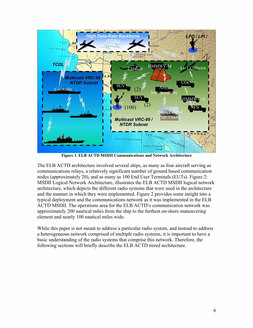
ELB ACTD Network Architecture The ELB ACTD MSDII Network Architecture was heavily dependent on UAV relays to form connectivity between ground nodes as diagramed in Figure 1: ELB ACT MSDII Communications and Network Architecture. There were several physical layer communication tiers used to establish the heterogeneous communications network. The primary radio systems used in the ELB ACTD consisted of the following:
• Tactical Common Data Link (TCDL), Harris Corporation • VRC-99, BAE Systems Corporation • NTDR by ITT Industries • 802.11B, Orinoco
6
Figure 1. ELB ACTD MSDII Communications and Network Architecture
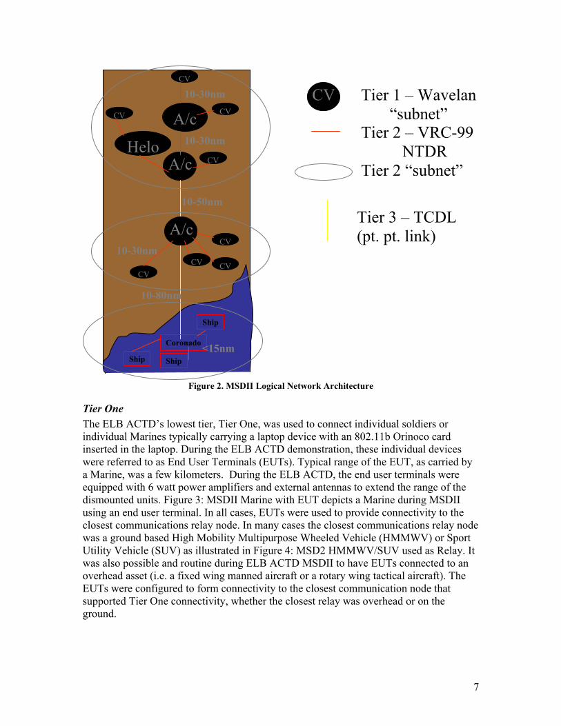
The ELB ACTD architecture involved several ships, as many as four aircraft serving as communications relays, a relatively significant number of ground based communication nodes (approximately 20), and as many as 100 End User Terminals (EUTs). Figure 2: MSDII Logical Network Architecture, illustrates the ELB ACTD MSDII logical network architecture, which depicts the different radio systems that were used in the architecture and the manner in which they were implemented. Figure 2 provides some insight into a typical deployment and the communications network as it was implemented in the ELB ACTD MSDII. The operations area for the ELB ACTD’s communication network was approximately 200 nautical miles from the ship to the furthest on-shore maneuvering element and nearly 100 nautical miles wide. While this paper is not meant to address a particular radio system, and instead to address a heterogeneous network comprised of multiple radio systems, it is important to have a basic understanding of the radio systems that comprise this network. Therefore, the following sections will briefly describe the ELB ACTD tiered architecture.
Multicast VRC-99 /
NTDR Subnet
High Data-Rate Backbone(TCDL)
Multicast VRC-99 /NTDR Subnet
LPD / LPI /
TCDL
(2)
(100)
Army Interoperability
San Onofre
UOC SUV
HMMWV-MCH46-D
Coronado
HMMWV-A
NFN
SUV
(2)EUT
EUT Collector
Demo Control (MCTSSA)
7
Figure 2. MSDII Logical Network Architecture
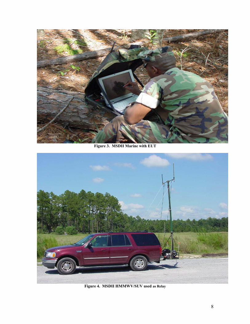
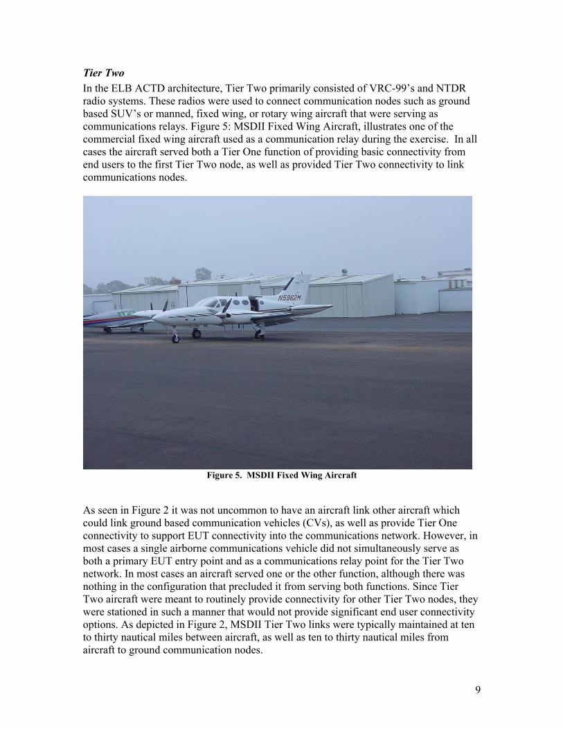
Tier One The ELB ACTD’s lowest tier, Tier One, was used to connect individual soldiers or individual Marines typically carrying a laptop device with an 802.11b Orinoco card inserted in the laptop. During the ELB ACTD demonstration, these individual devices were referred to as End User Terminals (EUTs). Typical range of the EUT, as carried by a Marine, was a few kilometers. During the ELB ACTD, the end user terminals were equipped with 6 watt power amplifiers and external antennas to extend the range of the dismounted units. Figure 3: MSDII Marine with EUT depicts a Marine during MSDII using an end user terminal. In all cases, EUTs were used to provide connectivity to the closest communications relay node. In many cases the closest communications relay node was a ground based High Mobility Multipurpose Wheeled Vehicle (HMMWV) or Sport Utility Vehicle (SUV) as illustrated in Figure 4: MSD2 HMMWV/SUV used as Relay. It was also possible and routine during ELB ACTD MSDII to have EUTs connected to an overhead asset (i.e. a fixed wing manned aircraft or a rotary wing tactical aircraft). The EUTs were configured to form connectivity to the closest communication node that supported Tier One connectivity, whether the closest relay was overhead or on the ground.
Coronado
Ship
Ship Ship
CV
Helo
A/c
A/c
CV
CV CV
CV
CVCV
CV
CV Tier 1 – Wavelan“subnet”
Tier 2 – VRC-99 NTDR Tier 2 “subnet”
Tier 3 – TCDL(pt. pt. link)
A/c
10-80nm
10-50nm
10-30nm
10-30nm
10-30nm
<15nm
8
Figure 3. MSDII Marine with EUT
Figure 4. MSDII HMMWV/SUV used as Relay
9
Tier Two In the ELB ACTD architecture, Tier Two primarily consisted of VRC-99’s and NTDR radio systems. These radios were used to connect communication nodes such as ground based SUV’s or manned, fixed wing, or rotary wing aircraft that were serving as communications relays. Figure 5: MSDII Fixed Wing Aircraft, illustrates one of the commercial fixed wing aircraft used as a communication relay during the exercise. In all cases the aircraft served both a Tier One function of providing basic connectivity from end users to the first Tier Two node, as well as provided Tier Two connectivity to link communications nodes.
Figure 5. MSDII Fixed Wing Aircraft
As seen in Figure 2 it was not uncommon to have an aircraft link other aircraft which could link ground based communication vehicles (CVs), as well as provide Tier One connectivity to support EUT connectivity into the communications network. However, in most cases a single airborne communications vehicle did not simultaneously serve as both a primary EUT entry point and as a communications relay point for the Tier Two network. In most cases an aircraft served one or the other function, although there was nothing in the configuration that precluded it from serving both functions. Since Tier Two aircraft were meant to routinely provide connectivity for other Tier Two nodes, they were stationed in such a manner that would not provide significant end user connectivity options. As depicted in Figure 2, MSDII Tier Two links were typically maintained at ten to thirty nautical miles between aircraft, as well as ten to thirty nautical miles from aircraft to ground communication nodes.
10
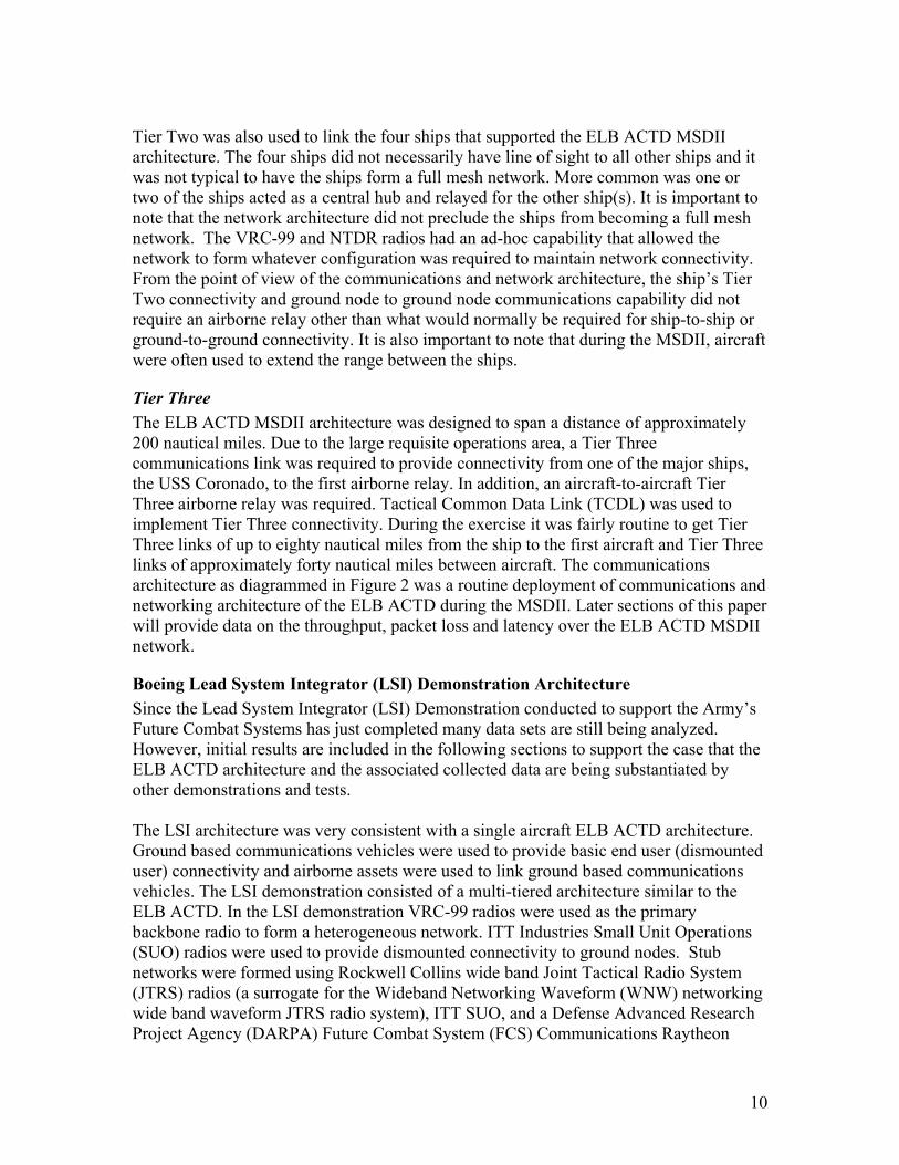
Tier Two was also used to link the four ships that supported the ELB ACTD MSDII architecture. The four ships did not necessarily have line of sight to all other ships and it was not typical to have the ships form a full mesh network. More common was one or two of the ships acted as a central hub and relayed for the other ship(s). It is important to note that the network architecture did not preclude the ships from becoming a full mesh network. The VRC-99 and NTDR radios had an ad-hoc capability that allowed the network to form whatever configuration was required to maintain network connectivity. From the point of view of the communications and network architecture, the ship’s Tier Two connectivity and ground node to ground node communications capability did not require an airborne relay other than what would normally be required for ship-to-ship or ground-to-ground connectivity. It is also important to note that during the MSDII, aircraft were often used to extend the range between the ships.
Tier Three The ELB ACTD MSDII architecture was designed to span a distance of approximately 200 nautical miles. Due to the large requisite operations area, a Tier Three communications link was required to provide connectivity from one of the major ships, the USS Coronado, to the first airborne relay. In addition, an aircraft-to-aircraft Tier Three airborne relay was required. Tactical Common Data Link (TCDL) was used to implement Tier Three connectivity. During the exercise it was fairly routine to get Tier Three links of up to eighty nautical miles from the ship to the first aircraft and Tier Three links of approximately forty nautical miles between aircraft. The communications architecture as diagrammed in Figure 2 was a routine deployment of communications and networking architecture of the ELB ACTD during the MSDII. Later sections of this paper will provide data on the throughput, packet loss and latency over the ELB ACTD MSDII network.
Boeing Lead System Integrator (LSI) Demonstration Architecture Since the Lead System Integrator (LSI) Demonstration conducted to support the Army’s Future Combat Systems has just completed many data sets are still being analyzed. However, initial results are included in the following sections to support the case that the ELB ACTD architecture and the associated collected data are being substantiated by other demonstrations and tests. The LSI architecture was very consistent with a single aircraft ELB ACTD architecture. Ground based communications vehicles were used to provide basic end user (dismounted user) connectivity and airborne assets were used to link ground based communications vehicles. The LSI demonstration consisted of a multi-tiered architecture similar to the ELB ACTD. In the LSI demonstration VRC-99 radios were used as the primary backbone radio to form a heterogeneous network. ITT Industries Small Unit Operations (SUO) radios were used to provide dismounted connectivity to ground nodes. Stub networks were formed using Rockwell Collins wide band Joint Tactical Radio System (JTRS) radios (a surrogate for the Wideband Networking Waveform (WNW) networking wide band waveform JTRS radio system), ITT SUO, and a Defense Advanced Research Project Agency (DARPA) Future Combat System (FCS) Communications Raytheon
11
directional antenna based communications system. Limited datasets from the LSI Demonstration are provided in following sections of this paper.
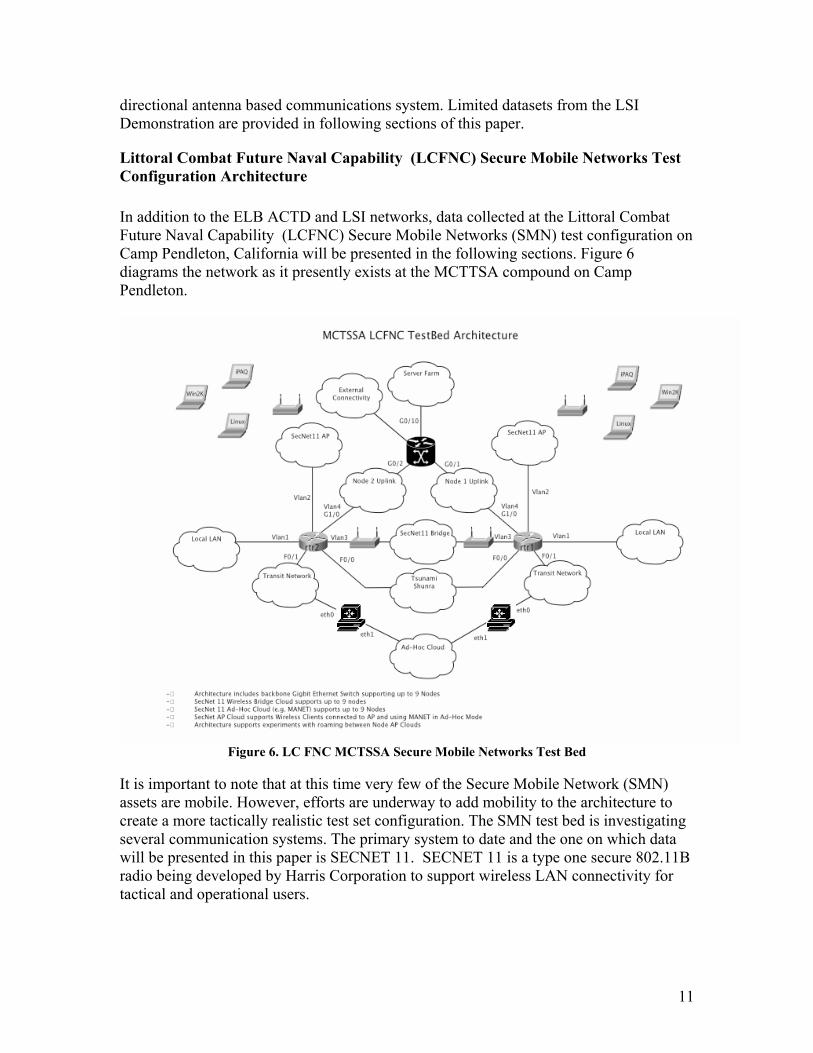
Littoral Combat Future Naval Capability (LCFNC) Secure Mobile Networks Test Configuration Architecture In addition to the ELB ACTD and LSI networks, data collected at the Littoral Combat Future Naval Capability (LCFNC) Secure Mobile Networks (SMN) test configuration on Camp Pendleton, California will be presented in the following sections. Figure 6 diagrams the network as it presently exists at the MCTTSA compound on Camp Pendleton.
Figure 6. LC FNC MCTSSA Secure Mobile Networks Test Bed
It is important to note that at this time very few of the Secure Mobile Network (SMN) assets are mobile. However, efforts are underway to add mobility to the architecture to create a more tactically realistic test set configuration. The SMN test bed is investigating several communication systems. The primary system to date and the one on which data will be presented in this paper is SECNET 11. SECNET 11 is a type one secure 802.11B radio being developed by Harris Corporation to support wireless LAN connectivity for tactical and operational users.
12
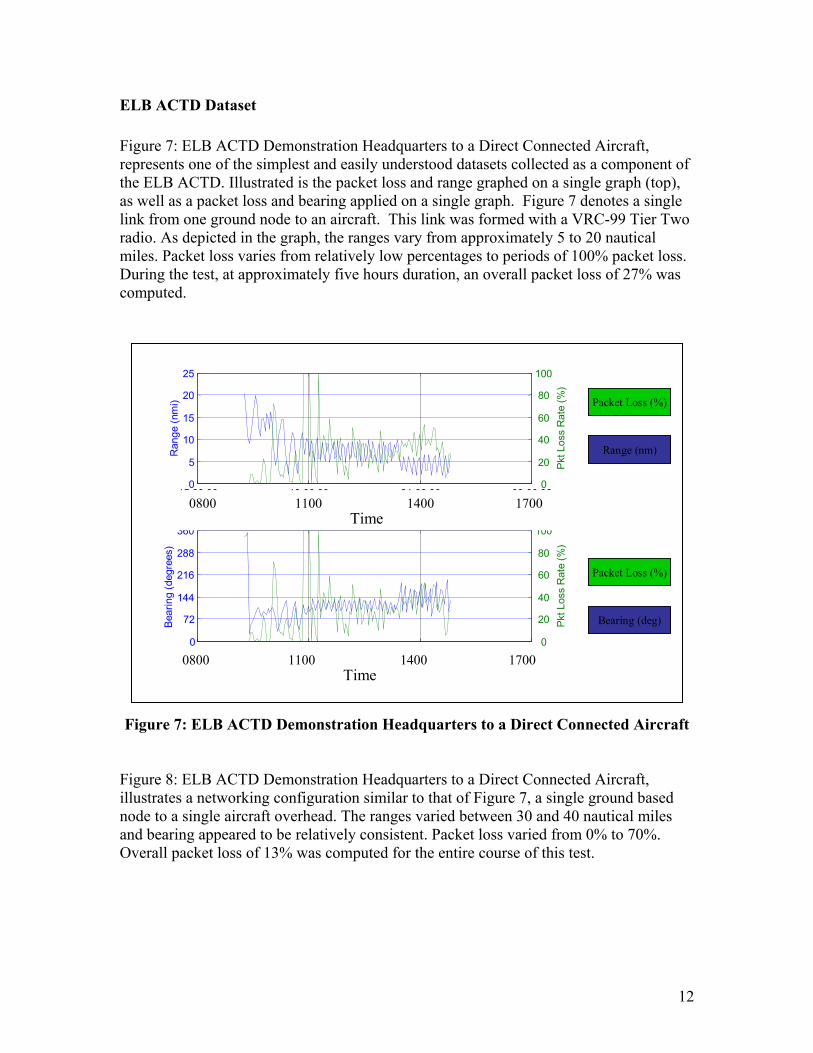
ELB ACTD Dataset Figure 7: ELB ACTD Demonstration Headquarters to a Direct Connected Aircraft, represents one of the simplest and easily understood datasets collected as a component of the ELB ACTD. Illustrated is the packet loss and range graphed on a single graph (top), as well as a packet loss and bearing applied on a single graph. Figure 7 denotes a single link from one ground node to an aircraft. This link was formed with a VRC-99 Tier Two radio. As depicted in the graph, the ranges vary from approximately 5 to 20 nautical miles. Packet loss varies from relatively low percentages to periods of 100% packet loss. During the test, at approximately five hours duration, an overall packet loss of 27% was computed.
Figure 7: ELB ACTD Demonstration Headquarters to a Direct Connected Aircraft
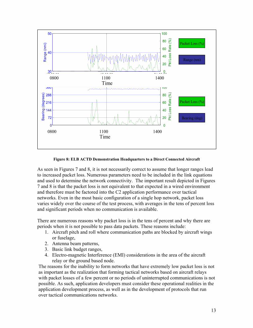
Figure 8: ELB ACTD Demonstration Headquarters to a Direct Connected Aircraft, illustrates a networking configuration similar to that of Figure 7, a single ground based node to a single aircraft overhead. The ranges varied between 30 and 40 nautical miles and bearing appeared to be relatively consistent. Packet loss varied from 0% to 70%. Overall packet loss of 13% was computed for the entire course of this test.
15:00:00 18:00:00 21:00:00 00:00:000
5
10
15
20
25
Time
Ran
ge (n
mi)
15:00:00 18:00:00 21:00:00 00:00:000
20
40
60
80
100
Pkt L
oss
Rat
e (%
)
15:00:00 18:00:00 21:00:00 00:00:000
72
144
216
288
360
Time
Bear
ing
(deg
rees
)
Bearing
15:00:00 18:00:00 21:00:00 00:00:000
20
40
60
80
100
Pkt L
oss
Rat
e (%
)
Packet Loss (%)
Range (nm)
Packet Loss (%)
Bearing (deg)
Packet Loss (%)
Range (nm)
Packet Loss (%)
Bearing (deg)
0800 1100 1400 1700Time
0800 1100 1400 17000800 1100 1400 1700Time
0800 1100 1400 1700Time
0800 1100 1400 17000800 1100 1400 1700Time
13
Figure 8: ELB ACTD Demonstration Headquarters to a Direct Connected Aircraft As seen in Figures 7 and 8, it is not necessarily correct to assume that longer ranges lead to increased packet loss. Numerous parameters need to be included in the link equations and used to determine the network connectivity. The important result depicted in Figures 7 and 8 is that the packet loss is not equivalent to that expected in a wired environment and therefore must be factored into the C2 application performance over tactical networks. Even in the most basic configuration of a single hop network, packet loss varies widely over the course of the test process, with averages in the tens of percent loss and significant periods when no communication is available. There are numerous reasons why packet loss is in the tens of percent and why there are periods when it is not possible to pass data packets. These reasons include:
1. Aircraft pitch and roll where communication paths are blocked by aircraft wings or fuselage,
2. Antenna beam patterns, 3. Basic link budget ranges, 4. Electro-magnetic Interference (EMI) considerations in the area of the aircraft
relay or the ground based node. The reasons for the inability to form networks that have extremely low packet loss is not as important as the realization that forming tactical networks based on aircraft relays with packet losses of a few percent or no periods of uninterrupted communications is not possible. As such, application developers must consider these operational realities in the application development process, as well as in the development of protocols that run over tactical communications networks.
15:00:00 18:00:00 21:00:0030
40
50
Time
Ran
ge (n
mi)
15:00:00 18:00:00 21:00:000
20
40
60
80
100
Pkt L
oss
Rat
e (%
)
15:00:00 18:00:00 21:00:000
72
144
216
288
360
Time
Bear
ing
(deg
rees
)
Bearing
15:00:00 18:00:00 21:00:000
20
40
60
80
100
Pkt L
oss
Rat
e (%
)
Packet Loss (%)
Range (nm)
Packet Loss (%)
Bearing (deg)
Packet Loss (%)
Range (nm)
Packet Loss (%)
Bearing (deg)
0800 1100 1400Time
0800 1100 14000800 1100 1400Time
0800 1100 1400Time
0800 1100 14000800 1100 1400Time
14
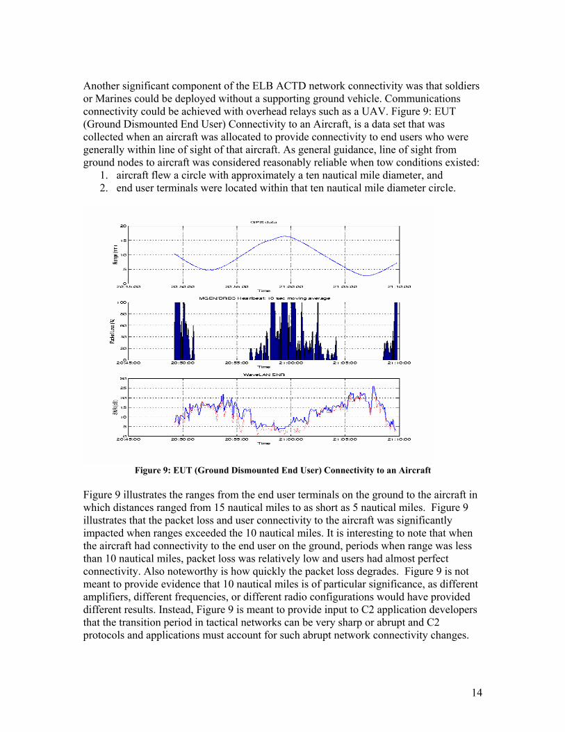
Another significant component of the ELB ACTD network connectivity was that soldiers or Marines could be deployed without a supporting ground vehicle. Communications connectivity could be achieved with overhead relays such as a UAV. Figure 9: EUT (Ground Dismounted End User) Connectivity to an Aircraft, is a data set that was collected when an aircraft was allocated to provide connectivity to end users who were generally within line of sight of that aircraft. As general guidance, line of sight from ground nodes to aircraft was considered reasonably reliable when tow conditions existed:
1. aircraft flew a circle with approximately a ten nautical mile diameter, and 2. end user terminals were located within that ten nautical mile diameter circle.
Figure 9: EUT (Ground Dismounted End User) Connectivity to an Aircraft
Figure 9 illustrates the ranges from the end user terminals on the ground to the aircraft in which distances ranged from 15 nautical miles to as short as 5 nautical miles. Figure 9 illustrates that the packet loss and user connectivity to the aircraft was significantly impacted when ranges exceeded the 10 nautical miles. It is interesting to note that when the aircraft had connectivity to the end user on the ground, periods when range was less than 10 nautical miles, packet loss was relatively low and users had almost perfect connectivity. Also noteworthy is how quickly the packet loss degrades. Figure 9 is not meant to provide evidence that 10 nautical miles is of particular significance, as different amplifiers, different frequencies, or different radio configurations would have provided different results. Instead, Figure 9 is meant to provide input to C2 application developers that the transition period in tactical networks can be very sharp or abrupt and C2 protocols and applications must account for such abrupt network connectivity changes.
15
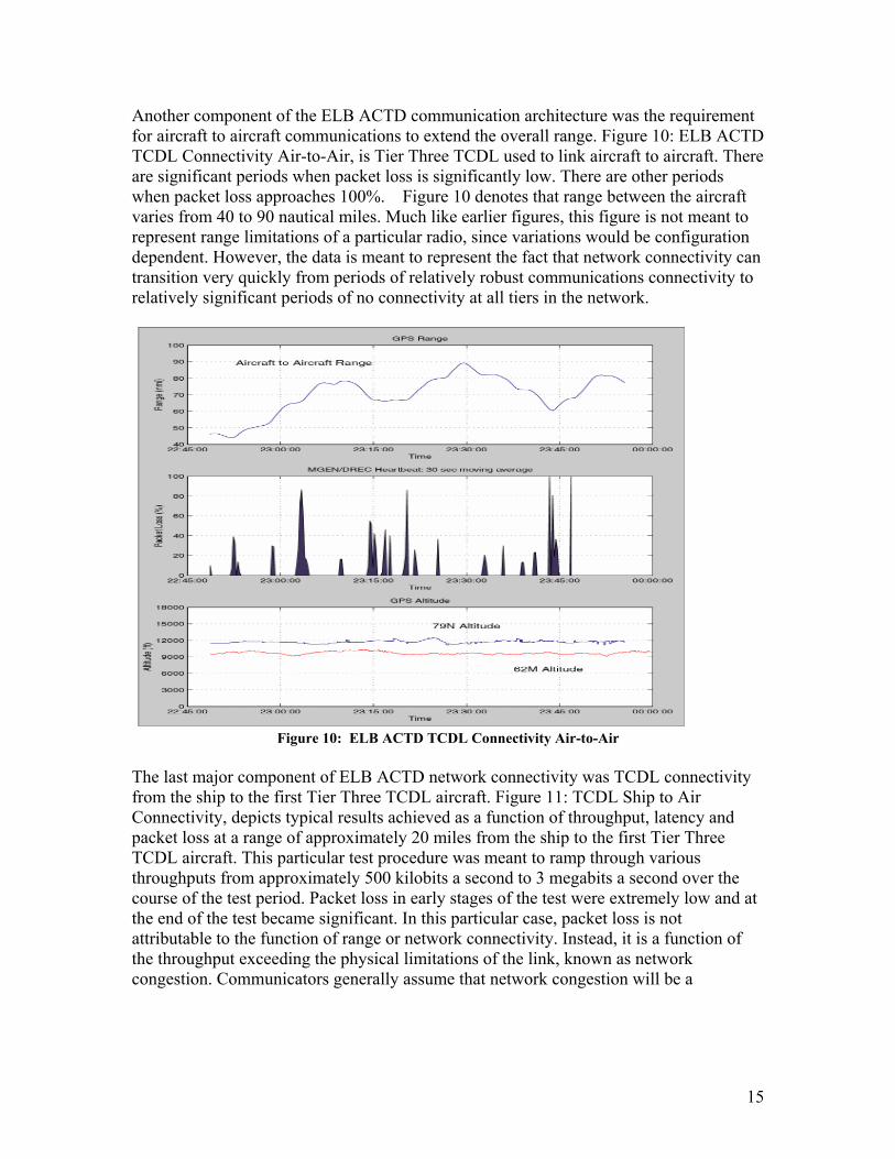
Another component of the ELB ACTD communication architecture was the requirement for aircraft to aircraft communications to extend the overall range. Figure 10: ELB ACTD TCDL Connectivity Air-to-Air, is Tier Three TCDL used to link aircraft to aircraft. There are significant periods when packet loss is significantly low. There are other periods when packet loss approaches 100%. Figure 10 denotes that range between the aircraft varies from 40 to 90 nautical miles. Much like earlier figures, this figure is not meant to represent range limitations of a particular radio, since variations would be configuration dependent. However, the data is meant to represent the fact that network connectivity can transition very quickly from periods of relatively robust communications connectivity to relatively significant periods of no connectivity at all tiers in the network.
Figure 10: ELB ACTD TCDL Connectivity Air-to-Air
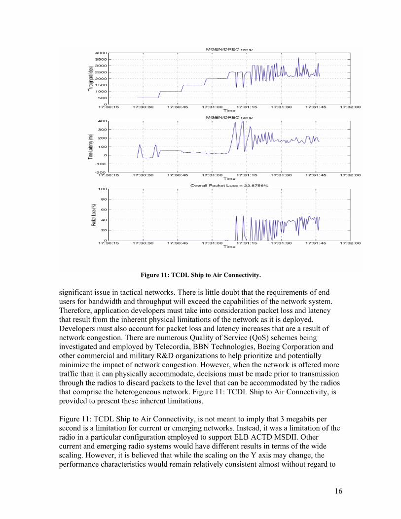
The last major component of ELB ACTD network connectivity was TCDL connectivity from the ship to the first Tier Three TCDL aircraft. Figure 11: TCDL Ship to Air Connectivity, depicts typical results achieved as a function of throughput, latency and packet loss at a range of approximately 20 miles from the ship to the first Tier Three TCDL aircraft. This particular test procedure was meant to ramp through various throughputs from approximately 500 kilobits a second to 3 megabits a second over the course of the test period. Packet loss in early stages of the test were extremely low and at the end of the test became significant. In this particular case, packet loss is not attributable to the function of range or network connectivity. Instead, it is a function of the throughput exceeding the physical limitations of the link, known as network congestion. Communicators generally assume that network congestion will be a
16
Figure 11: TCDL Ship to Air Connectivity.
significant issue in tactical networks. There is little doubt that the requirements of end users for bandwidth and throughput will exceed the capabilities of the network system. Therefore, application developers must take into consideration packet loss and latency that result from the inherent physical limitations of the network as it is deployed. Developers must also account for packet loss and latency increases that are a result of network congestion. There are numerous Quality of Service (QoS) schemes being investigated and employed by Telecordia, BBN Technologies, Boeing Corporation and other commercial and military R&D organizations to help prioritize and potentially minimize the impact of network congestion. However, when the network is offered more traffic than it can physically accommodate, decisions must be made prior to transmission through the radios to discard packets to the level that can be accommodated by the radios that comprise the heterogeneous network. Figure 11: TCDL Ship to Air Connectivity, is provided to present these inherent limitations. Figure 11: TCDL Ship to Air Connectivity, is not meant to imply that 3 megabits per second is a limitation for current or emerging networks. Instead, it was a limitation of the radio in a particular configuration employed to support ELB ACTD MSDII. Other current and emerging radio systems would have different results in terms of the wide scaling. However, it is believed that while the scaling on the Y axis may change, the performance characteristics would remain relatively consistent almost without regard to
17
which radio system under test. Application developers must take into account the impact of increasing throughput requirements placed on the network by the C2 applications. It is important to note that other testing efforts which have data yet to be released suggest that attempts to make TCDL or comparable high data rate directional antenna systems into networked systems (This refers to systems that are capable of rapidly switching from pointing at one node to pointing at another as the would be required in a multipoint networked configuration) substantially increases packet loss. Perhaps intuitively, one would expect higher loss due in large part to the constant, or nearly so, requirement to switch or re-steer antennas and reform network connectivity. It is hoped that data on high data rate directional antenna network approaches will be provided in future papers. At this time, it is reasonable to suggest that TCDL’s periods of low packets loss are attributable to high antenna gain and steered directional antennas, creating a challenge to support high data rate directional antenna networking (as compared to point-to-point links) on a very small percent of the nodes in the network.
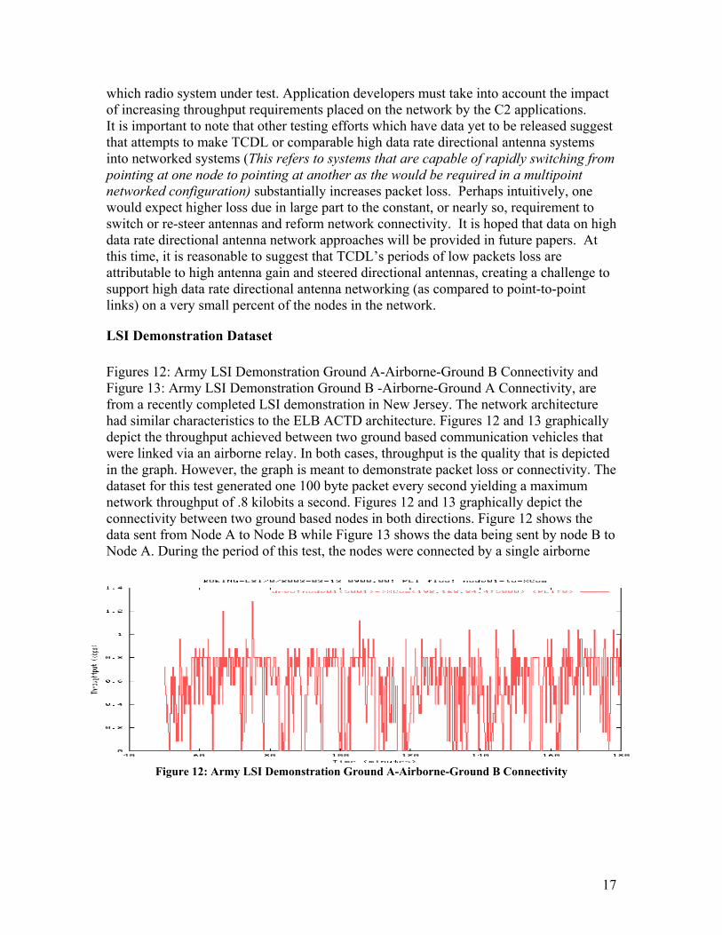
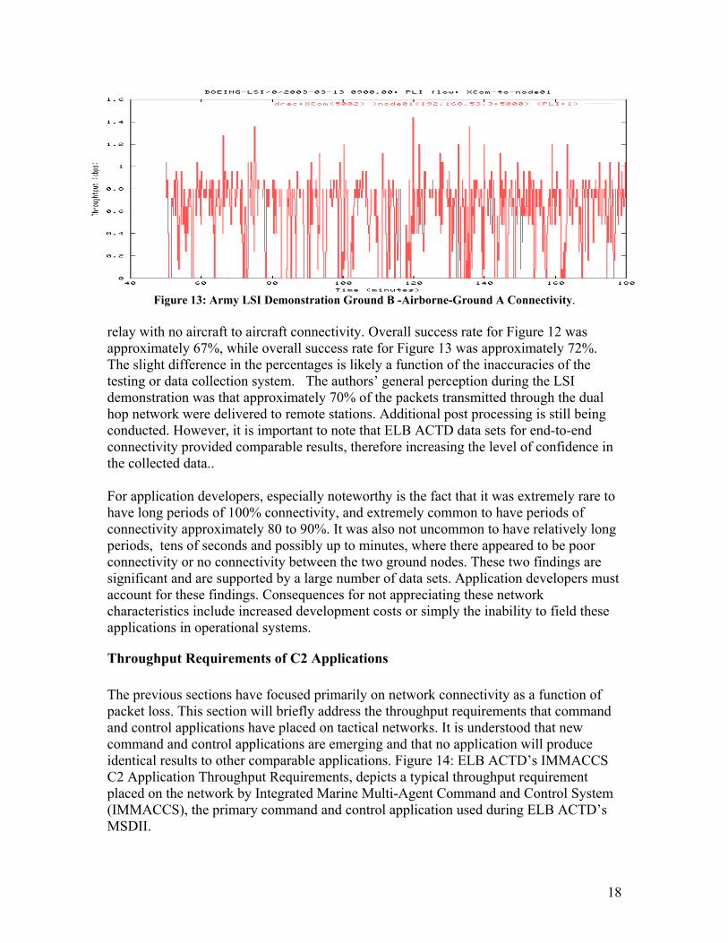
LSI Demonstration Dataset Figures 12: Army LSI Demonstration Ground A-Airborne-Ground B Connectivity and Figure 13: Army LSI Demonstration Ground B -Airborne-Ground A Connectivity, are from a recently completed LSI demonstration in New Jersey. The network architecture had similar characteristics to the ELB ACTD architecture. Figures 12 and 13 graphically depict the throughput achieved between two ground based communication vehicles that were linked via an airborne relay. In both cases, throughput is the quality that is depicted in the graph. However, the graph is meant to demonstrate packet loss or connectivity. The dataset for this test generated one 100 byte packet every second yielding a maximum network throughput of .8 kilobits a second. Figures 12 and 13 graphically depict the connectivity between two ground based nodes in both directions. Figure 12 shows the data sent from Node A to Node B while Figure 13 shows the data being sent by node B to Node A. During the period of this test, the nodes were connected by a single airborne
Figure 12: Army LSI Demonstration Ground A-Airborne-Ground B Connectivity
18
Figure 13: Army LSI Demonstration Ground B -Airborne-Ground A Connectivity.
relay with no aircraft to aircraft connectivity. Overall success rate for Figure 12 was approximately 67%, while overall success rate for Figure 13 was approximately 72%. The slight difference in the percentages is likely a function of the inaccuracies of the testing or data collection system. The authors’ general perception during the LSI demonstration was that approximately 70% of the packets transmitted through the dual hop network were delivered to remote stations. Additional post processing is still being conducted. However, it is important to note that ELB ACTD data sets for end-to-end connectivity provided comparable results, therefore increasing the level of confidence in the collected data.. For application developers, especially noteworthy is the fact that it was extremely rare to have long periods of 100% connectivity, and extremely common to have periods of connectivity approximately 80 to 90%. It was also not uncommon to have relatively long periods, tens of seconds and possibly up to minutes, where there appeared to be poor connectivity or no connectivity between the two ground nodes. These two findings are significant and are supported by a large number of data sets. Application developers must account for these findings. Consequences for not appreciating these network characteristics include increased development costs or simply the inability to field these applications in operational systems.
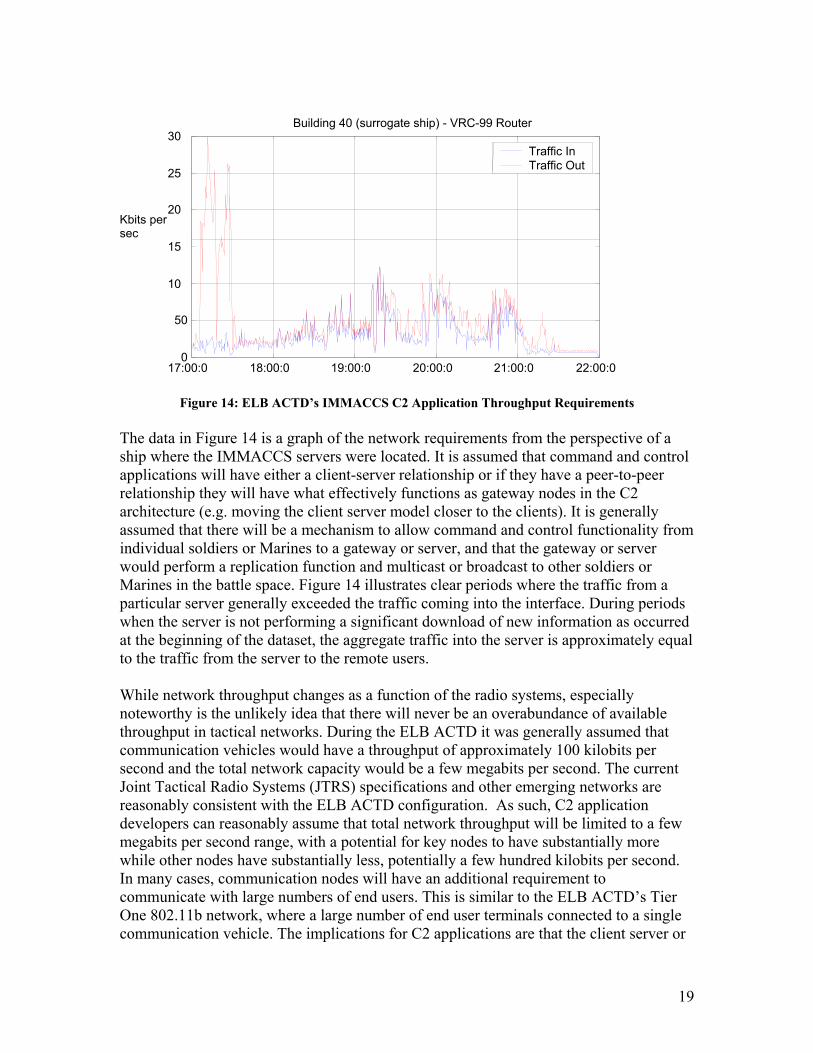
Throughput Requirements of C2 Applications The previous sections have focused primarily on network connectivity as a function of packet loss. This section will briefly address the throughput requirements that command and control applications have placed on tactical networks. It is understood that new command and control applications are emerging and that no application will produce identical results to other comparable applications. Figure 14: ELB ACTD’s IMMACCS C2 Application Throughput Requirements, depicts a typical throughput requirement placed on the network by Integrated Marine Multi-Agent Command and Control System (IMMACCS), the primary command and control application used during ELB ACTD’s MSDII.
19
Figure 14: ELB ACTD’s IMMACCS C2 Application Throughput Requirements
The data in Figure 14 is a graph of the network requirements from the perspective of a ship where the IMMACCS servers were located. It is assumed that command and control applications will have either a client-server relationship or if they have a peer-to-peer relationship they will have what effectively functions as gateway nodes in the C2 architecture (e.g. moving the client server model closer to the clients). It is generally assumed that there will be a mechanism to allow command and control functionality from individual soldiers or Marines to a gateway or server, and that the gateway or server would perform a replication function and multicast or broadcast to other soldiers or Marines in the battle space. Figure 14 illustrates clear periods where the traffic from a particular server generally exceeded the traffic coming into the interface. During periods when the server is not performing a significant download of new information as occurred at the beginning of the dataset, the aggregate traffic into the server is approximately equal to the traffic from the server to the remote users. While network throughput changes as a function of the radio systems, especially noteworthy is the unlikely idea that there will never be an overabundance of available throughput in tactical networks. During the ELB ACTD it was generally assumed that communication vehicles would have a throughput of approximately 100 kilobits per second and the total network capacity would be a few megabits per second. The current Joint Tactical Radio Systems (JTRS) specifications and other emerging networks are reasonably consistent with the ELB ACTD configuration. As such, C2 application developers can reasonably assume that total network throughput will be limited to a few megabits per second range, with a potential for key nodes to have substantially more while other nodes have substantially less, potentially a few hundred kilobits per second. In many cases, communication nodes will have an additional requirement to communicate with large numbers of end users. This is similar to the ELB ACTD’s Tier One 802.11b network, where a large number of end user terminals connected to a single communication vehicle. The implications for C2 applications are that the client server or
17:00:0 18:00:0 19:00:0 20:00:0 21:00:0 22:00:00
50 10
15
20
25
30
Kbits per sec
Building 40 (surrogate ship) - VRC-99 Router
Traffic In Traffic Out
20
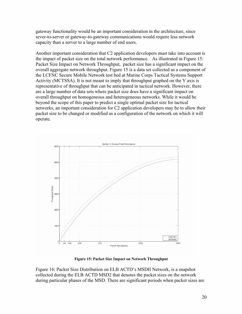
gateway functionality would be an important consideration in the architecture, since sever-to-server or gateway-to-gateway communications would require less network capacity than a server to a large number of end users. Another important consideration that C2 application developers must take into account is the impact of packet size on the total network performance. As illustrated in Figure 15: Packet Size Impact on Network Throughput, packet size has a significant impact on the overall aggregate network throughput. Figure 15 is a data set collected as a component of the LCFNC Secure Mobile Network test bed at Marine Corps Tactical Systems Support Activity (MCTSSA). It is not meant to imply that throughput graphed on the Y axis is representative of throughput that can be anticipated in tactical network. However, there are a large number of data sets where packet size does have a significant impact on overall throughput on homogeneous and heterogeneous networks. While it would be beyond the scope of this paper to predict a single optimal packet size for tactical networks, an important consideration for C2 application developers may be to allow their packet size to be changed or modified as a configuration of the network on which it will operate.
Figure 15: Packet Size Impact on Network Throughput
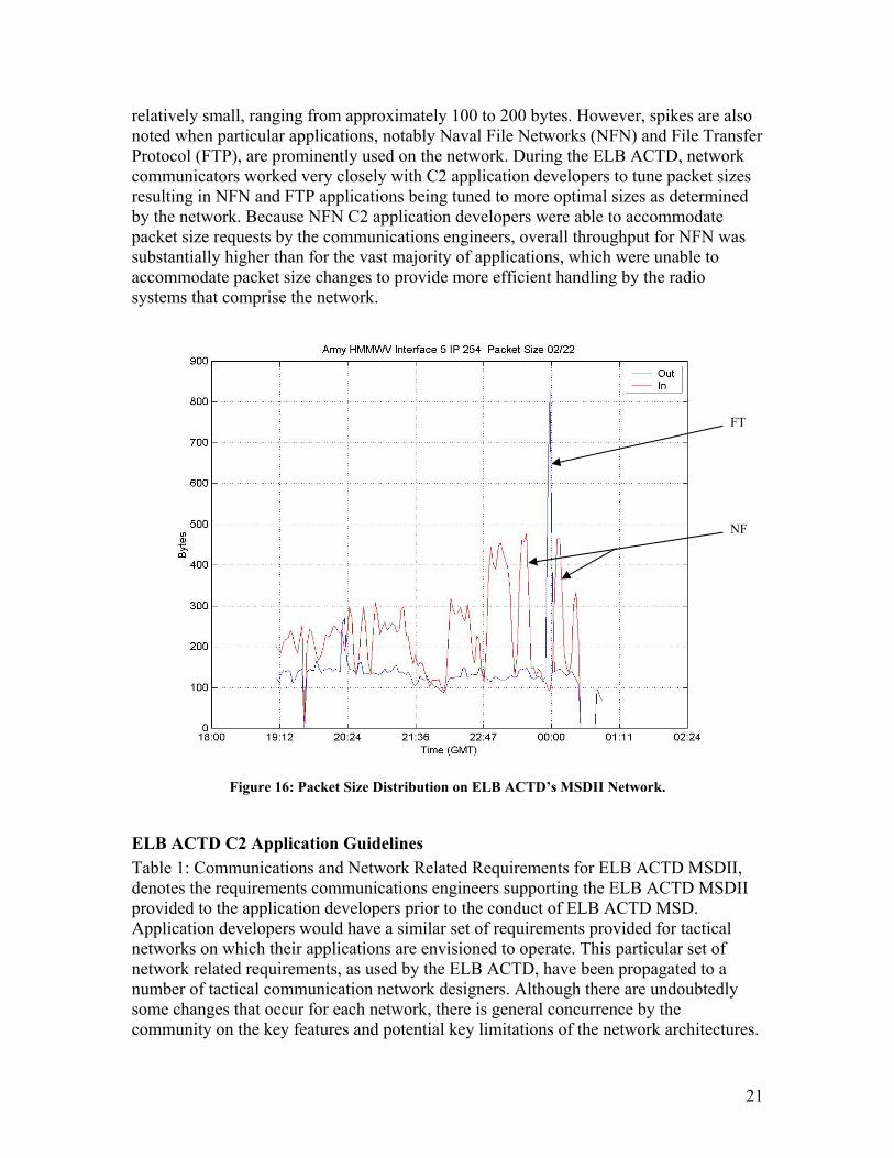
Figure 16: Packet Size Distribution on ELB ACTD’s MSDII Network, is a snapshot collected during the ELB ACTD MSD2 that denotes the packet sizes on the network during particular phases of the MSD. There are significant periods when packet sizes are
21
relatively small, ranging from approximately 100 to 200 bytes. However, spikes are also noted when particular applications, notably Naval File Networks (NFN) and File Transfer Protocol (FTP), are prominently used on the network. During the ELB ACTD, network communicators worked very closely with C2 application developers to tune packet sizes resulting in NFN and FTP applications being tuned to more optimal sizes as determined by the network. Because NFN C2 application developers were able to accommodate packet size requests by the communications engineers, overall throughput for NFN was substantially higher than for the vast majority of applications, which were unable to accommodate packet size changes to provide more efficient handling by the radio systems that comprise the network.
Figure 16: Packet Size Distribution on ELB ACTD’s MSDII Network.
ELB ACTD C2 Application Guidelines Table 1: Communications and Network Related Requirements for ELB ACTD MSDII, denotes the requirements communications engineers supporting the ELB ACTD MSDII provided to the application developers prior to the conduct of ELB ACTD MSD. Application developers would have a similar set of requirements provided for tactical networks on which their applications are envisioned to operate. This particular set of network related requirements, as used by the ELB ACTD, have been propagated to a number of tactical communication network designers. Although there are undoubtedly some changes that occur for each network, there is general concurrence by the community on the key features and potential key limitations of the network architectures.
FT
NF
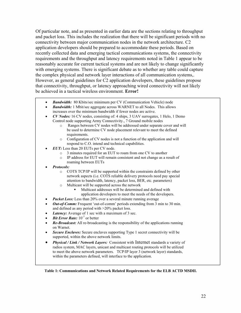
Of particular note, and as presented in earlier data are the sections relating to throughput and packet loss. This includes the realization that there will be significant periods with no connectivity between major communication nodes in the network architecture. C2 application developers should be prepared to accommodate these periods. Based on recently collected data and emerging tactical communications systems, the connectivity requirements and the throughput and latency requirements noted in Table 1 appear to be reasonably accurate for current tactical systems and are not likely to change significantly with emerging systems. There is significant debate as to whether any table could capture the complex physical and network layer interactions of all communication systems,. However, as general guidelines for C2 application developers, these guidelines propose that connectivity, throughput, or latency approaching wired connectivity will not likely be achieved in a tactical wireless environment. Error!
Tab
• •
•
•
•
• •
• • •
•
•
Bandwidth: 80 Kbits/sec minimum per CV (Communication Vehicle) node Bandwidth: 1 Mbit/sec aggregate across WARNET to all Nodes. This allows increases over the minimum bandwidth if fewer nodes are active. CV Nodes: 16 CV nodes, consisting of: 4 ships, 3 UAV surrogates, 1 Helo, 1 Demo Control node supporting Army Connectivity., 7 Ground mobile nodes
o Ranges between CV nodes will be addressed under separate cover and willbe used to determine CV node placement relevant to meet the defined requirements.
o Configuration of CV nodes is not a function of the application and will respond to C.O. intend and technical capabilities.
EUT: Less than 20 EUTs per CV node. o 3 minutes required for an EUT to roam from one CV to another o IP address for EUT will remain consistent and not change as a result of
roaming between EUTs Protocols:
o COTS TCP/IP will be supported within the constraints defined by other network aspects (i.e. COTS reliable delivery protocols need pay special attention to bandwidth, latency, packet loss, BER, etc. parameters)
o Multicast will be supported across the network Multicast addresses will be determined and defined with
application developers to meet the needs of the developers. Packet Loss: Less than 20% over a several minute running average Out-of-Comm: Frequent ‘out-of-comm’ periods extending from 3 min to 30 min. and defined as any period with >20% packet loss. Latency: Average of 1 sec with a maximum of 3 sec. Bit Error Rate: 10-7 or better Re-Broadcast: All re-broadcasting is the responsibility of the applications running on Warnet. Secure Enclaves: Secure enclaves supporting Type 1 secret connectivity will be supported, within the above network limits. Physical / Link / Network Layers: Consistent with Internet standards a variety of radios system, MAC layers, unicast and multicast routing protocols will be utilized to meet the above network parameters. TCP/IP layer 3 (network layer) standards, within the parameters defined, will interface to the application.
22
le 1: Communications and Network Related Requirements for the ELB ACTD MSDII.
23
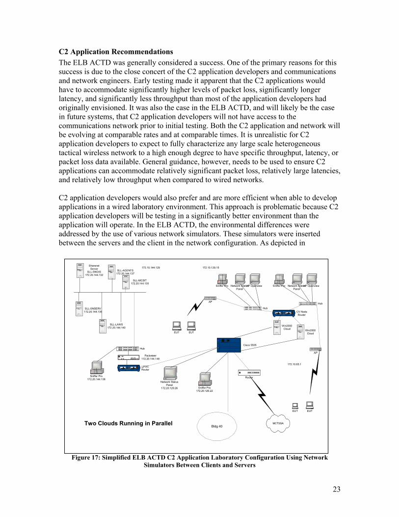
C2 Application Recommendations The ELB ACTD was generally considered a success. One of the primary reasons for this success is due to the close concert of the C2 application developers and communications and network engineers. Early testing made it apparent that the C2 applications would have to accommodate significantly higher levels of packet loss, significantly longer latency, and significantly less throughput than most of the application developers had originally envisioned. It was also the case in the ELB ACTD, and will likely be the case in future systems, that C2 application developers will not have access to the communications network prior to initial testing. Both the C2 application and network will be evolving at comparable rates and at comparable times. It is unrealistic for C2 application developers to expect to fully characterize any large scale heterogeneous tactical wireless network to a high enough degree to have specific throughput, latency, or packet loss data available. General guidance, however, needs to be used to ensure C2 applications can accommodate relatively significant packet loss, relatively large latencies, and relatively low throughput when compared to wired networks. C2 application developers would also prefer and are more efficient when able to develop applications in a wired laboratory environment. This approach is problematic because C2 application developers will be testing in a significantly better environment than the application will operate. In the ELB ACTD, the environmental differences were addressed by the use of various network simulators. These simulators were inserted between the servers and the client in the network configuration. As depicted in
Figure 17: Simplified ELB ACTD C2 Application Laboratory Configuration Using Network
Simulators Between Clients and Servers
Bldg 40
SharenetServer
SLL-SNOIS172.20.144.132
SD
Cisco 1720
BRIS/T
CONSOLE
AUXWIC 0 OK
OKB2B1
WIC 1 OK
DSUCPU
LNK100FDX
S3
LOOP
LP
LFOCRouter
SD
OK1
OK2
PS1PS2TEMP
100/15,230v~20/30Hz, 8. 0/1.75 A
BA NK11x 2x 3x 4x
5x 6x 7x 8x
BA NK21x 2x 3x 4x
5x 6x 7x 8x
1
5
2
6
3
7
4
8
BANK 21
5
2
6
3
7
4
8
BANK1
CO NSO LE Packeteer172.20.144.148
SD
1100C AT5MOD ULARJAC KPA NEL
Lucen t
1 2 3 4
25 26 27 28
5 6
29 30
7 8 9 10
3 1 32 33 34
11 12
35 36
13 14 15 16
37 38 39 40
17 18
41 42
19 20 21 22
43 44 45 46
23 24
47 48
Hub
S D
1100CAT5MODULARJACKPANEL
Lucent
1 2 3 4
25 26 27 28
5 6
29 30
7 8 9 10
31 32 33 34
11 12
35 36
13 14 15 16
37 38 39 40
17 18
41 42
19 20 21 22
43 44 45 46
23 24
47 48
Hub
HP OpenviewSniffer Pro Network StatusPanel
Sniffer Pro172.20.129.22
Sniffer Pro172.20.144.138
SLL-LAWS172.20.144.140
SLL-SNSERV172.20.144.135
SLL-AGENTS172.20.144.137
172.10.65.1
172.10.144.129 172.10.129.15
SD
C ataly st8 5 00
Po we r S up pl y 0CISCO YSTEMSS P ow er S upp ly 1
S wi tchP ro ces sor
SERI ES
Cisco 5505
SLL-MCSIT172.20.144.135
Network StatusPanel
172.20.129.26
Win2000Cloud
Two Clouds Running in Parallel
Win2000Cloud
Router
MCTSSA
SD
1100CAT5MODULARJACKPANELLucent
1 2 3 4
25 26 27 28
5 6
29 30
7 8 9 10
31 32 33 34
11 12
35 36
13 14 15 16
37 38 39 40
17 18
41 42
19 20 21 22
43 44 45 46
23 24
47 48
Hub
HP OpenviewSniffer Pro Network StatusPanel
AP
EUT EUT
AP
EUT EUT
SD
Cisco 1720
BRIS/T
CONSOLE
AUXWIC 0 OK
OKB2B1
WIC 1 OK
DSUCPU
LNK100FDX
S3
LOOP
LP
CV NodeRouter
24
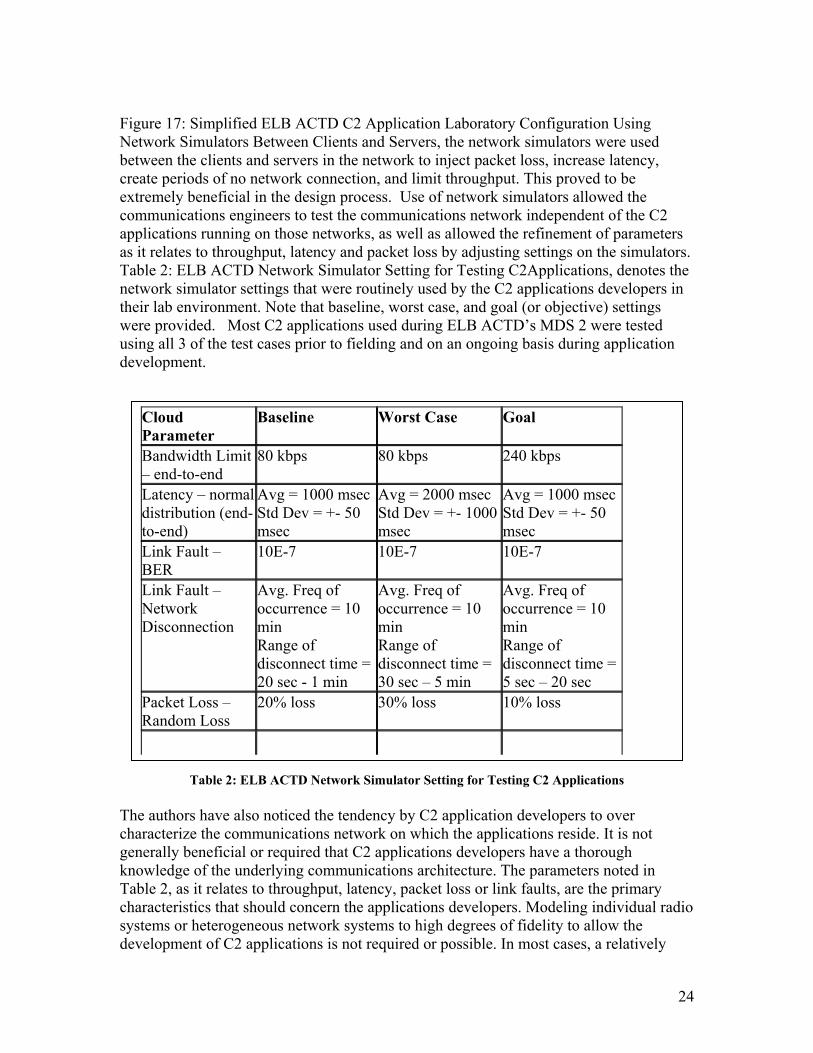
Figure 17: Simplified ELB ACTD C2 Application Laboratory Configuration Using Network Simulators Between Clients and Servers, the network simulators were used between the clients and servers in the network to inject packet loss, increase latency, create periods of no network connection, and limit throughput. This proved to be extremely beneficial in the design process. Use of network simulators allowed the communications engineers to test the communications network independent of the C2 applications running on those networks, as well as allowed the refinement of parameters as it relates to throughput, latency and packet loss by adjusting settings on the simulators. Table 2: ELB ACTD Network Simulator Setting for Testing C2Applications, denotes the network simulator settings that were routinely used by the C2 applications developers in their lab environment. Note that baseline, worst case, and goal (or objective) settings were provided. Most C2 applications used during ELB ACTD’s MDS 2 were tested using all 3 of the test cases prior to fielding and on an ongoing basis during application development.
Table 2: ELB ACTD Network Simulator Setting for Testing C2 Applications
The authors have also noticed the tendency by C2 application developers to over characterize the communications network on which the applications reside. It is not generally beneficial or required that C2 applications developers have a thorough knowledge of the underlying communications architecture. The parameters noted in Table 2, as it relates to throughput, latency, packet loss or link faults, are the primary characteristics that should concern the applications developers. Modeling individual radio systems or heterogeneous network systems to high degrees of fidelity to allow the development of C2 applications is not required or possible. In most cases, a relatively
Cloud Parameter
Baseline Worst Case Goal
Bandwidth Limit – end-to-end
80 kbps 80 kbps 240 kbps
Latency – normal distribution (end-to-end)
Avg = 1000 msecStd Dev = +- 50 msec
Avg = 2000 msec Std Dev = +- 1000 msec
Avg = 1000 msec Std Dev = +- 50 msec
Link Fault – BER
10E-7 10E-7 10E-7
Link Fault – Network Disconnection
Avg. Freq of occurrence = 10 min Range of disconnect time = 20 sec - 1 min
Avg. Freq of occurrence = 10 min Range of disconnect time = 30 sec – 5 min
Avg. Freq of occurrence = 10 min Range of disconnect time = 5 sec – 20 sec
Packet Loss – Random Loss
20% loss 30% loss 10% loss
25
simple and inexpensive network simulator with reasonably configured throughput, latency and packet loss characteristics will prove extremely beneficial in the application development process. Requiring applications developers to operate in an environment that is substantially degraded from a wired network environment has proven on numerous occasions to be a benefit in ensuring that C2 applications function in realistic tactical environments. The benefit of incorporating these networking considerations into the C2 development process, ultimately in the test architecture, is truly noteworthy. These considerations will drive the system design, and more fundamentally, embraces open, modular system design concepts. Failure to consider these factors result in applications that cannot be integrated efficiently into the overall system architectures, cannot easily be evolved or maintained through their life cycle.
Conclusions Both communications engineers and applications engineers need to work in an integrated fashion to ensure that the war fighter is provided new, effective C2 applications and enhanced communications to conduct their required missions. With a lack of technical coordination, the delivered C2 products will lack the required capability for the end user. Unfortunately, this degraded performance often is attributed to poor communications. Undoubtedly, if wired-like communication capabilities in a tactical environment, significantly more C2 applications would function in the field as they do in the laboratory. The data and discussion in this paper is presented to make the case that it is simply not possible now or in the future to provide wireless connectivity comparable in throughput, latency and packet loss to wired connectivity. Therefore, the only remedy includes:
1. C2 applications better accommodate a less than perfect and less than ubiquitous tactical communications network
2. Applications and communications engineers need to work in an integrated fashion to ensure that developers have the necessary tools in the laboratory setting to effectively simulate tactical networks.
When C2 application developers and communications engineer are able to share this design responsibility the war fighter will benefit with the inevitable command and control functionality. The recognition by the C4ISR development community that this level of technical and programmatic commitment to the integration of communications and C2 system design processes is required will ultimately result in better technology products, more seamless transition to fielded systems, and realizable spiral development processes.
26
References Brown, Wayne, Vince Marano, Timothy Krout. “FCS Scalable Mobile Networks
Demonstration Performance and Validation Results.” MILCOM 2003 accepted paper.
Durbano, Steven, Joe Matkowski. “Secure Wireless Networking SecNet 11 Testing.” April 2003. “ELB ACTD Full System Test 1 Data Report.” 2000. “ELB ACTD Limited Operational Evaluation 6 Data Report.” 2000. “ELB ACTD Major System Demonstration 2 Data Report.” 2001. “FCS Concept and Technology Phase Scalable Mobile Network Demonstration Final
Report.” Boeing. Doc # D786-10064-7. 2003.