Embed Size (px)
Citation preview
Network Layer 4-1
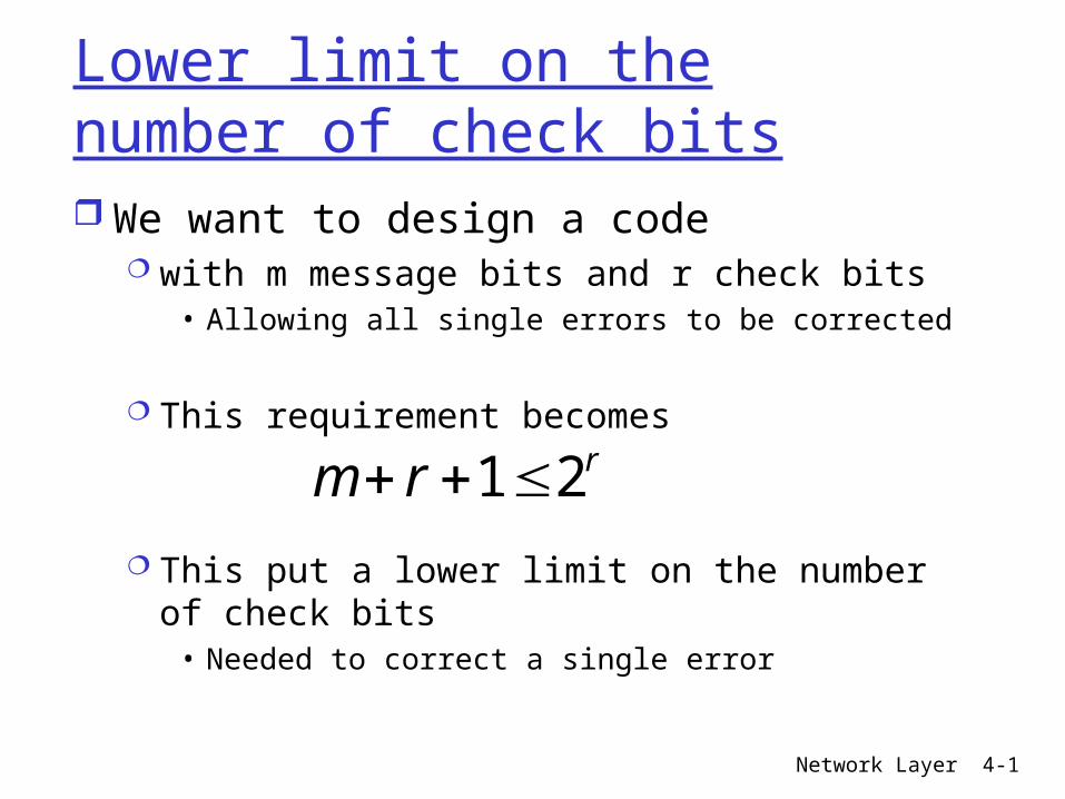
Lower limit on the number of check bits We want to design a code
with m message bits and r check bits • Allowing all single errors to be corrected
This requirement becomes
This put a lower limit on the number of check bits
• Needed to correct a single error
rrm 21
Network Layer 4-2
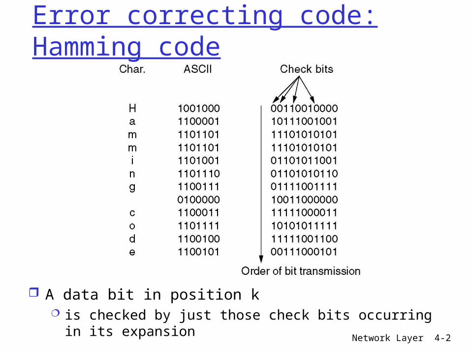
Error correcting code: Hamming code
A data bit in position k is checked by just those check bits occurring in its
expansion
Network Layer 4-3
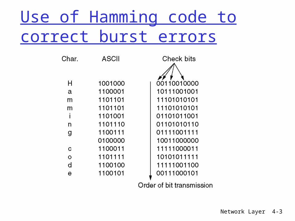
Use of Hamming code to correct burst errors
Network Layer 4-4
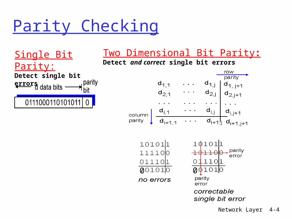
Parity Checking
Single Bit Parity:Detect single bit errors
Two Dimensional Bit Parity:Detect and correct single bit errors
0 0
Network Layer 4-5
Error detecting codes
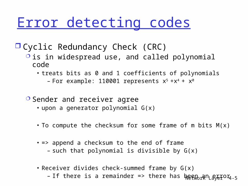
Cyclic Redundancy Check (CRC) is in widespread use, and called polynomial code
• treats bits as 0 and 1 coefficients of polynomials – For example: 110001 represents x5 +x4 + x0
Sender and receiver agree • upon a generator polynomial G(x)
• To compute the checksum for some frame of m bits M(x)
• => append a checksum to the end of frame– such that polynomial is divisible by G(x)
• Receiver divides check-summed frame by G(x)– If there is a remainder => there has been an error
Network Layer 4-6
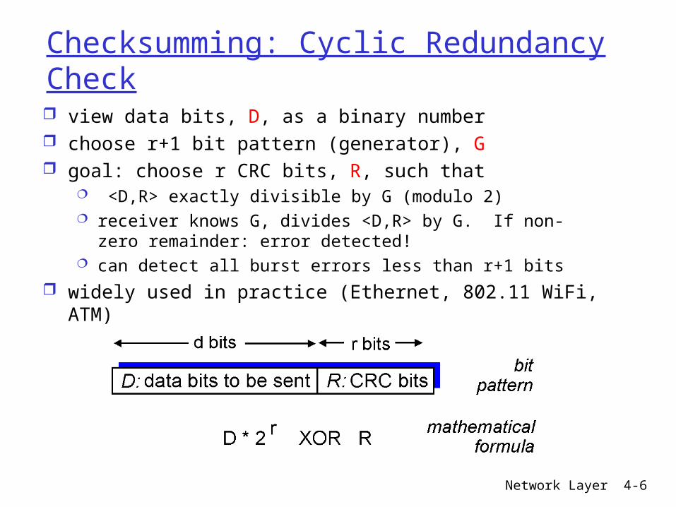
Checksumming: Cyclic Redundancy Check view data bits, D, as a binary number choose r+1 bit pattern (generator), G goal: choose r CRC bits, R, such that
<D,R> exactly divisible by G (modulo 2) receiver knows G, divides <D,R> by G. If non-zero
remainder: error detected! can detect all burst errors less than r+1 bits
widely used in practice (Ethernet, 802.11 WiFi, ATM)
Network Layer 4-7
Algorithm for computing the checksum Let r be the degree of G(x)
Append r zeros to the low-order end of the frame
=> xr M(x)
Divide the bit string corresponding to G(x) Into the bit string corresponding xr M(x) using
• Modulo 2 division
Subtract the remainder from xr M(x) The result is the checksumed frame to be
transmitted
Network Layer 4-8
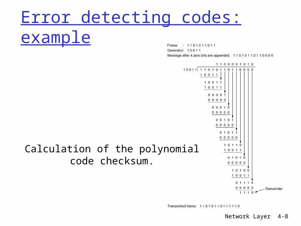
Error detecting codes: example
Calculation of the polynomial code checksum.
Network Layer 4-9
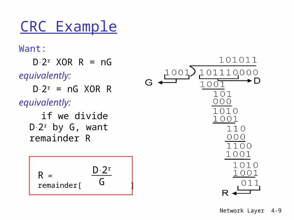
CRC ExampleWant:
D.2r XOR R = nGequivalently:
D.2r = nG XOR R equivalently: if we divide D.2r by
G, want remainder R
R = remainder[ ]D.2r
G

Network Layer 4-10
Link Layer
5.1 Introduction and services
5.2 Error detection and correction
5.3Multiple access protocols
5.4 Link-layer Addressing
5.5 Ethernet
5.6 Link-layer switches 5.7 PPP 5.8 Link Virtualization:
ATM, MPLS
Network Layer 4-11
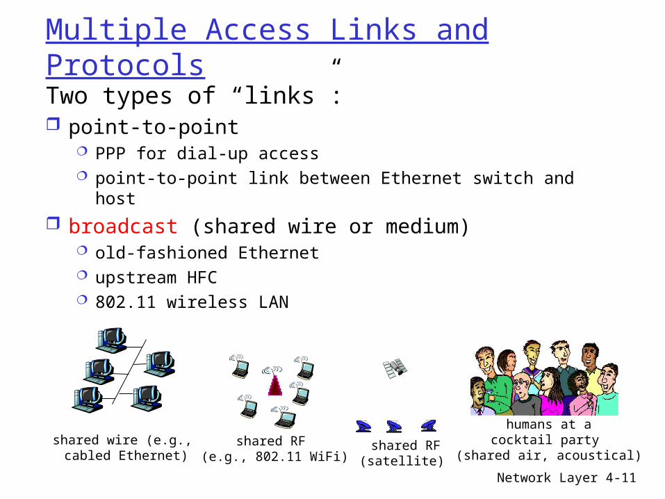
Multiple Access Links and Protocols
Two types of “links”: point-to-point
PPP for dial-up access point-to-point link between Ethernet switch and host
broadcast (shared wire or medium) old-fashioned Ethernet upstream HFC 802.11 wireless LAN
shared wire (e.g., cabled Ethernet)
shared RF (e.g., 802.11 WiFi)
shared RF(satellite)
humans at acocktail party
(shared air, acoustical)
Network Layer 4-12
Multiple Access protocols single shared broadcast channel two or more simultaneous transmissions by nodes:
interference collision if node receives two or more signals at the same
time
multiple access protocol distributed algorithm that determines how nodes
share channel, i.e., determine when node can transmit
communication about channel sharing must use channel itself! no out-of-band channel for coordination
Network Layer 4-13
CSMA (Carrier Sense Multiple Access)
CSMA: listen before transmit:If channel sensed idle: transmit entire frame If channel sensed busy, defer transmission
human analogy: don’t interrupt others!

Network Layer 4-14
CSMA/CD (Collision Detection)CSMA/CD: carrier sensing, deferral as in CSMA
collisions detected within short time colliding transmissions aborted, reducing
channel wastage collision detection:
easy in wired LANs: measure signal strengths, compare transmitted, received signals
difficult in wireless LANs: received signal strength overwhelmed by local transmission strength
human analogy: the polite conversationalist

Network Layer 4-15
Link Layer
5.1 Introduction and services
5.2 Error detection and correction
5.3Multiple access protocols
5.4 Link-layer Addressing
5.5 Ethernet
5.6 Link-layer switches 5.7 PPP 5.8 Link Virtualization:
ATM, MPLS

Network Layer 4-16
Multiple Access Links and Protocols
Two types of “links”: point-to-point
PPP for dial-up access point-to-point link between Ethernet switch and host
broadcast (shared wire or medium) old-fashioned Ethernet upstream HFC 802.11 wireless LAN
shared wire (e.g., cabled Ethernet)
shared RF (e.g., 802.11 WiFi)
shared RF(satellite)
humans at acocktail party
(shared air, acoustical)
Network Layer 4-17
LANs structure LANs
Use a multi-access channel as basis for communication
• Broadcast channel
Key issue• Determine who gets to use the channel when
– There is a competition for it
Medium Access Control protocols of data link layer
• Determines who goes next on a multi-access channel
• MAC sublayer is especially important in LANs
Network Layer 4-18
Dynamic channel allocation in LANs and MANs Work in this area based on 2
assumptions Single channel
• Available for all communication
Collision assumption• If 2 frames are simultaneously sent => collision
• A collided frame must be sent again later
• There are no errors other than those generated by collisions
Network Layer 4-19
Multiple Access protocols single shared broadcast channel two or more simultaneous transmissions by nodes:
interference collision if node receives two or more signals at the same
time
multiple access protocol distributed algorithm that determines how nodes
share channel, i.e., determine when node can transmit
communication about channel sharing must use channel itself! no out-of-band channel for coordination
Network Layer 4-20
MAC function: arbitration
Imagine trying to get thru an intersection When all traffic light are out
• You all want to use the intersection
• But you had better use it one at a time
• cannot allow cars from every direction to enter intersection– At the same time without having serious collisions
Data frames can collide if devices send any time During collision, LAN is unusable
• Not too different from a car crash in middle of an intersection
MAC arbitrate the use of physical medium To avoid collisions or recover when they occur

Network Layer 4-21
CSMA (Carrier Sense Multiple Access)
CSMA: listen before transmit:If channel sensed idle: transmit entire frame If channel sensed busy, defer transmission
human analogy: don’t interrupt others!
Network Layer 4-22
CSMA/CD (Collision Detection)CSMA/CD: carrier sensing, deferral as in CSMA
collisions detected within short time colliding transmissions aborted, reducing
channel wastage collision detection:
easy in wired LANs: measure signal strengths, compare transmitted, received signals
difficult in wireless LANs: received signal strength overwhelmed by local transmission strength
human analogy: the polite conversationalist
Network Layer 4-23
CSMA with Collision Detection: operational description A user who wishes to transmit
1) listen to see if the channel is free. • If channel is idle => it transmits
• Otherwise, keeps on listening until channel is free– Then transmits immediately (1-persistent)
2) during transmission keeps listening to detect collisions
• If a collision is detected => stops transmission immediately– Quickly terminating saves time and bandwidth
• And wait a random time before goes back to step 1
CSMA/CD is widely used on LANs (basis of Ethernet)
Network Layer 4-24
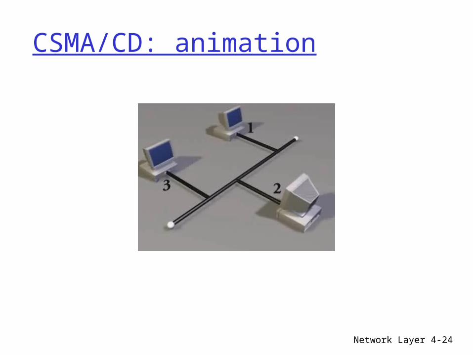
CSMA/CD: animation
Network Layer 4-25
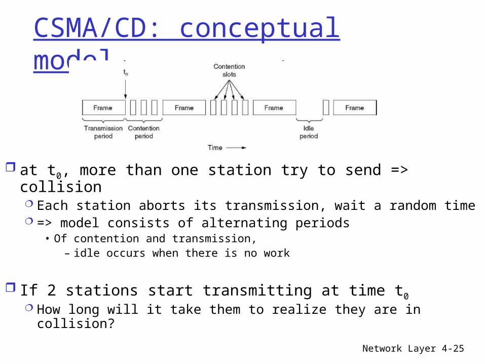
CSMA/CD: conceptual model
at t0, more than one station try to send => collision Each station aborts its transmission, wait a random time => model consists of alternating periods
• Of contention and transmission, – idle occurs when there is no work
If 2 stations start transmitting at time t0 How long will it take them to realize they are in collision?
Network Layer 4-26
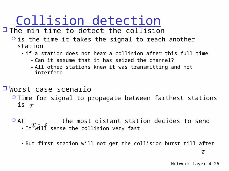
Collision detection The min time to detect the collision
is the time it takes the signal to reach another station• if a station does not hear a collision after this full time
– Can it assume that it has seized the channel?– All other stations knew it was transmitting and not interfere
Worst case scenario Time for signal to propagate between farthest stations
is
At the most distant station decides to send• It will sense the collision very fast
• But first station will not get the collision burst till after
Network Layer 4-27
Contention period
In the worst case, a station cannot be sure It has seized the channel until it has
transmitted for• Without hearing a collision
2
Network Layer 4-28
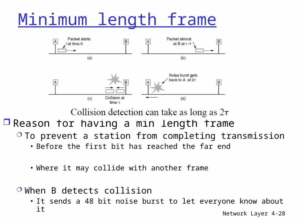
Minimum length frame
Reason for having a min length frame To prevent a station from completing transmission
• Before the first bit has reached the far end
• Where it may collide with another frame
When B detects collision • It sends a 48 bit noise burst to let everyone know about it
Network Layer 4-29
Minimum length frame (cont’d) If a station tries to send a very short frame
It might happen that sender finishes sending • Before the noise burst arrives at
• A frame must take more than to send– that transmission is still taking place when noise gets back
For a 10 Mbps LAN with a max length of 2500 meters and 4 repeaters
The round trip delay = 50 microseconds
The small frame is 500 bits (at 10 Mbps, 1 bit take 100 ns)• With some margin of safety this was added to 512 or 64 bytes
2
2
Network Layer 4-30
Network speed impact
As network speed goes up The min frame length must go up
Or the maximum cable length must come down
For a 250-meter LAN Operating at 1 Gbps
The min frame size should be 640 bytes
Network Layer 4-31
Binary backoff exponential algorithm How is randomization done in case of collision?
After a collision, time is divided into discrete slots• Whose length is set to 512 bit times or 51.2 microseconds
After the first collision • Each station waits for 0 or 1 slots.
– If both pick the same number =>
• Each one picks between 0, 1, 2, or 3 slots– If collision again => pick from 0 to 23 -1
• After i collisions a random # between 0 and 2i -1 is chosen– After 10 collisions => number is frozen at 1023 slots
– After 16 collisions => give up
Network Layer 4-32
In-class exercise Let A and B be 2 stations attempting to transmit
on Ethernet Each has a steady stream of frames ready to send
• A’s frame are numbered: A1, A2, … B’s are similarly #ered
Let T = 51.2 microseconds = exponential backoff unit
Suppose A and B simultaneously attempt to send frame 1, collide and
• happen to choose backoff times – 0.T and 1.T respectively, meaning A wins the race
B will attempt to retransmit B1 while A transmit A2
Network Layer 4-33
In-class exercise (cont’d)
These first attempts will collide but A backoffs for either 0xT or 1xT
While B backoffs for time equal to one of 0xT, …, 3xT
Give the probability that A wins the second backoff race
• immediately after the first collision
Network Layer 4-34
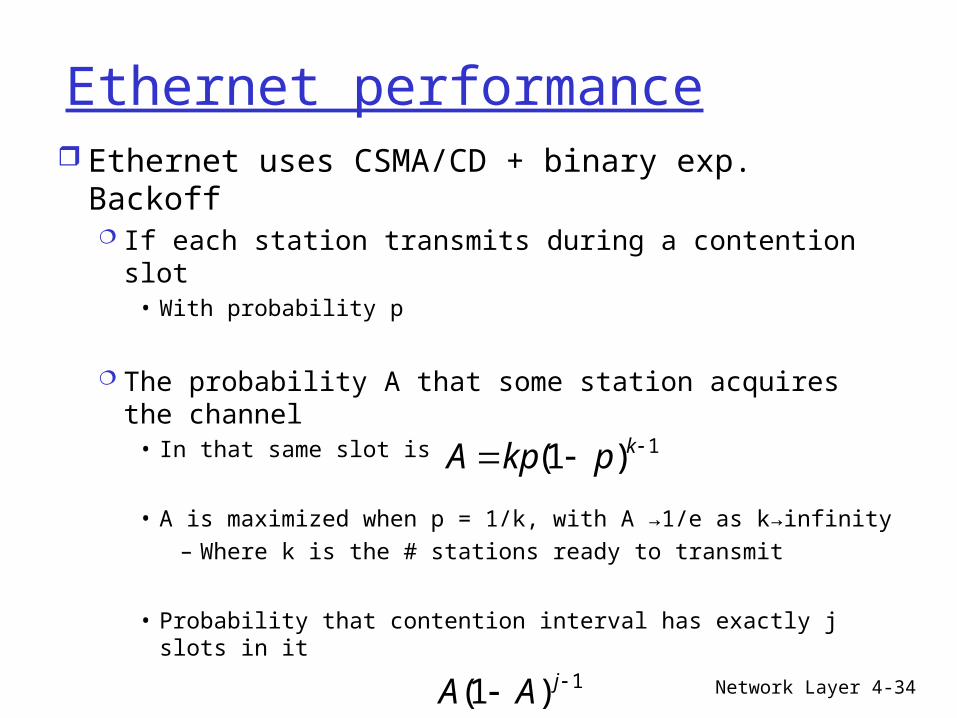
Ethernet performance Ethernet uses CSMA/CD + binary exp. Backoff
If each station transmits during a contention slot• With probability p
The probability A that some station acquires the channel
• In that same slot is
• A is maximized when p = 1/k, with A →1/e as k→infinity – Where k is the # stations ready to transmit
• Probability that contention interval has exactly j slots in it
1)1( kpkpA
1)1( jAA
Network Layer 4-35
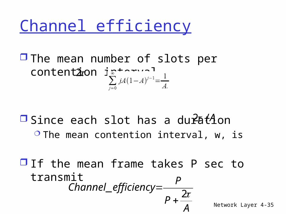
Channel efficiency
The mean number of slots per contention interval
Since each slot has a duration The mean contention interval, w, is
If the mean frame takes P sec to transmit
2
A/2
AP
PefficiencyChannel 2
_
Network Layer 4-36
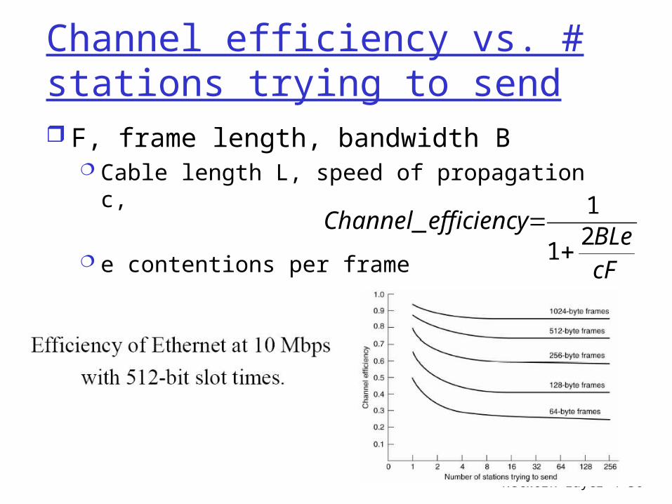
Channel efficiency vs. # stations trying to send F, frame length, bandwidth B
Cable length L, speed of propagation c,
e contentions per frame
cFBLe
efficiencyChannel2
1
1_