Embed Size (px)
Citation preview
Network Layer 4-1
Part of slides provided by J.F Kurose and K.W. Ross, All Rights Reserved
Chapter 4Network Layer
Communication NetworksP. Demeester
Computer networking -A top-down approach featuring the internet4th Edition, 2008Addison WesleyJames F. Kurose, Keith W. RossISBN 0-321-49770-8
Network Layer 4-2
Chapter 4 outline
4.1 Introduction and Network Service Models4.2 Routing Principles4.3 Hierarchical Routing4.4 The Internet (IP) Protocol4.5 Routing in the Internet4.6 What’s Inside a Router4.7 IPv64.8 Multicast Routing4.9 Mobility
Network Layer 4-3
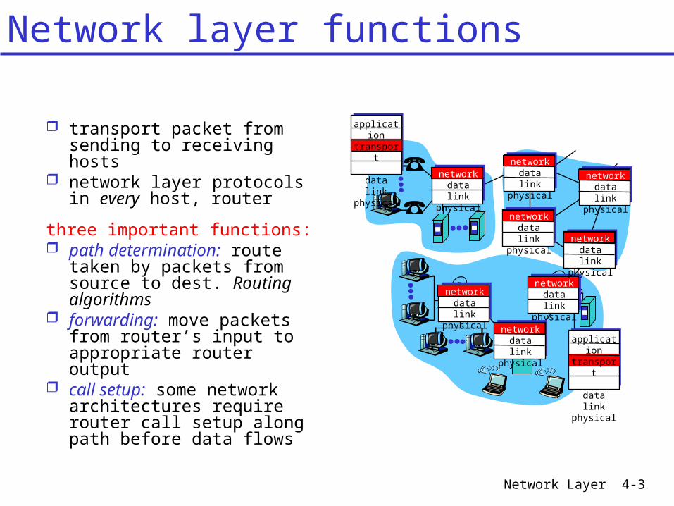
transport packet from sending to receiving hosts
network layer protocols in every host, router
three important functions: path determination: route
taken by packets from source to dest. Routing algorithms
forwarding: move packets from router’s input to appropriate router output
call setup: some network architectures require router call setup along path before data flows
networkdata linkphysical
networkdata linkphysical
networkdata linkphysical
networkdata linkphysical
networkdata linkphysical
networkdata linkphysical
networkdata linkphysical
networkdata linkphysical
application
transportnetworkdata linkphysical
application
transportnetworkdata linkphysical
Network layer functions
Network Layer 4-4
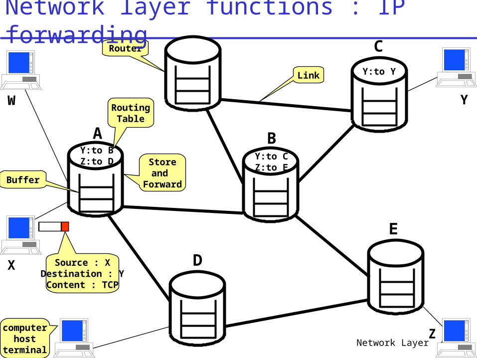
A B
C
D
E
Y:to BZ:to D Y:to C
Z:to E
Y:to Y
Source : XDestination : YContent : TCP
Storeand
Forward
RoutingTable
Buffer
Router
Link
computerhost
terminal
W
X
Y
Z
Network layer functions : IP forwarding
Network Layer 4-5
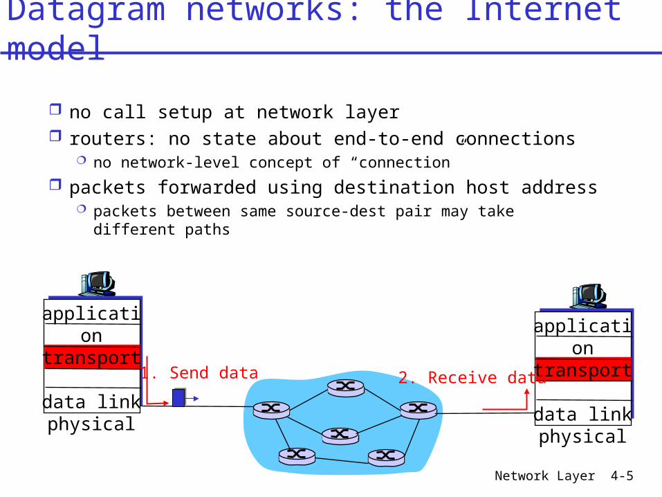
no call setup at network layer routers: no state about end-to-end connections
no network-level concept of “connection”
packets forwarded using destination host address packets between same source-dest pair may take
different paths
application
transportnetworkdata linkphysical
application
transportnetworkdata linkphysical
1. Send data 2. Receive data
Datagram networks: the Internet model
Network Layer 4-6
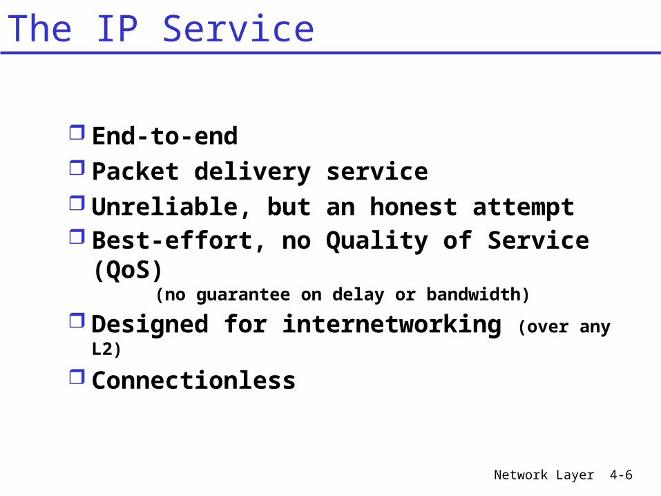
End-to-end Packet delivery service Unreliable, but an honest attempt Best-effort, no Quality of Service
(QoS)(no guarantee on delay or bandwidth)
Designed for internetworking (over any L2)
Connectionless
The IP Service
Network Layer 4-7
Chapter 4 outline
4.1 Introduction and Network Service Models4.2 Routing Principles4.3 Hierarchical Routing
4.4 The Internet (IP) Protocol 4.4.1 IPv4 addressing 4.4.2 Moving a datagram from source to
destination 4.4.3 Datagram format 4.4.4 IP fragmentation 4.4.5 ICMP: Internet Control Message Protocol 4.4.6 DHCP: Dynamic Host Configuration Protocol 4.4.7 NAT: Network Address Translation
4.5 Routing in the Internet4.6 What’s Inside a Router4.7 IPv64.8 Multicast Routing4.9 Mobility
Network Layer 4-8
Chapter 4 outline
4.4 The Internet (IP) Protocol 4.4.1 IPv4 addressing 4.4.2 Moving a datagram from source to
destination 4.4.3 Datagram format 4.4.4 IP fragmentation 4.4.5 ICMP: Internet Control Message
Protocol 4.4.6 DHCP: Dynamic Host Configuration
Protocol 4.4.7 NAT: Network Address Translation
Network Layer 4-9
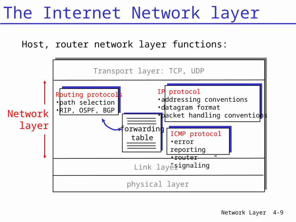
forwardingtable
Host, router network layer functions:
Routing protocols•path selection•RIP, OSPF, BGP
IP protocol•addressing conventions•datagram format•packet handling conventions
ICMP protocol•error reporting•router “signaling”
Transport layer: TCP, UDP
Link layer
physical layer
Networklayer
The Internet Network layer

Network Layer 4-10
[0.0.0.0-128.0.0.0[HP : 15.0.0.0
128 networks16 million addr/network
16k networks64k addr/network
2 M networks, 256 addr/network
IP address format : 4 octets, decimal notation, separation by dotexample : 157.193.122.10range : 0 - 255 (corresponds to 0000 0000 - 1111 1111 or 00-FF)
Two parts : network part and host part
Class A 0 Network Host
Class B 10 Network Host
Class C 110 Network Host
Class D 1110 Multicast address
Class E 11110 Reserved for future use
[128.0.0.0-192.0.0.0[UGent : 157.193.0.0
address space
157.193.122.10
network host
UGent network : 157.193 (64k hosts)
Address Format - Address Classes
Network Layer 4-11
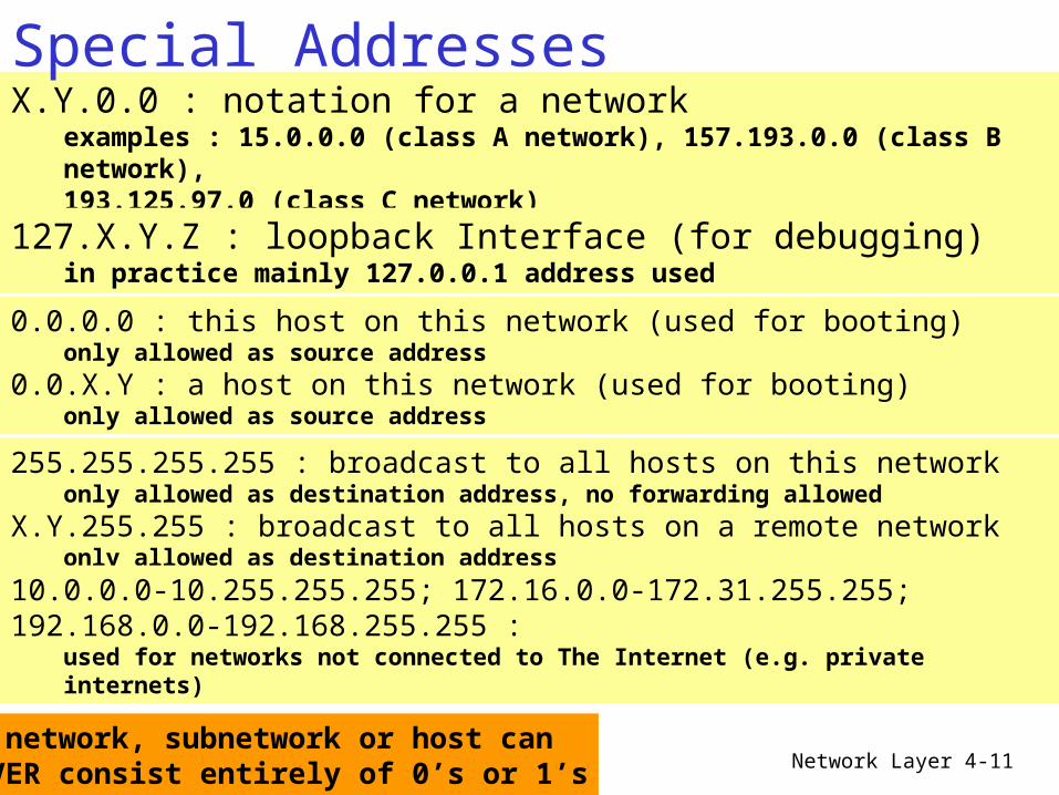
X.Y.0.0 : notation for a networkexamples : 15.0.0.0 (class A network), 157.193.0.0 (class B network), 193.125.97.0 (class C network)
127.X.Y.Z : loopback Interface (for debugging)in practice mainly 127.0.0.1 address used
0.0.0.0 : this host on this network (used for booting)only allowed as source address
0.0.X.Y : a host on this network (used for booting)only allowed as source address
255.255.255.255 : broadcast to all hosts on this networkonly allowed as destination address, no forwarding allowed
X.Y.255.255 : broadcast to all hosts on a remote networkonly allowed as destination address
A network, subnetwork or host can NEVER consist entirely of 0’s or 1’s
10.0.0.0-10.255.255.255; 172.16.0.0-172.31.255.255; 192.168.0.0-192.168.255.255 :
used for networks not connected to The Internet (e.g. private internets)
Special Addresses
Network Layer 4-12
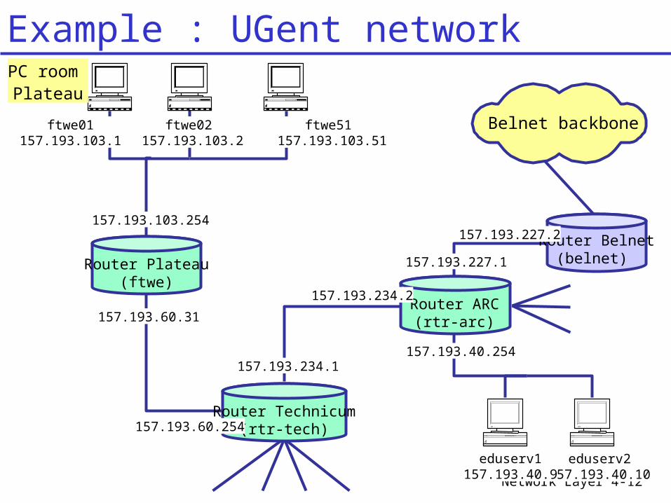
Router Plateau(ftwe)
157.193.103.254
eduserv2157.193.40.10
eduserv1157.193.40.9
157.193.40.254
157.193.227.1
Router Belnet(belnet)
157.193.227.2
Router ARC(rtr-arc)
157.193.234.2
157.193.234.1
Router Technicum(rtr-tech)157.193.60.254
157.193.60.31
ftwe01157.193.103.1
ftwe02 157.193.103.2
ftwe51 157.193.103.51
PC room Plateau
Belnet backbone
Example : UGent network
Network Layer 4-13
Router Plateau(ftwe)
157.193.103.254
eduserv2157.193.40.10
eduserv1157.193.40.9
157.193.40.254
157.193.227.1
Router Belnet(belnet)
157.193.227.2
Router ARC(rtr-arc)
157.193.234.2
157.193.234.1
Router Technicum(rtr-tech)157.193.60.254
157.193.60.31
ftwe01157.193.103.1
ftwe02 157.193.103.2
ftwe51 157.193.103.51
PC room Plateau
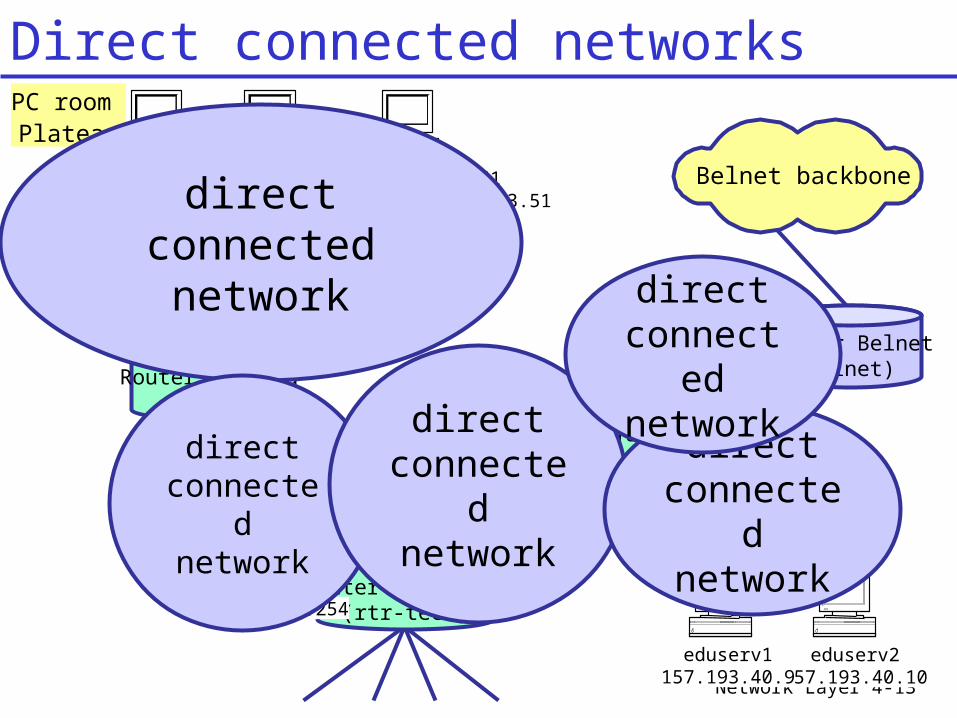
Belnet backbonedirect connected network
direct connected network
direct connected network
direct connected network
direct connecte
d network
Direct connected networks
Network Layer 4-14
Router Plateau(ftwe)
157.193.103.254
eduserv2157.193.40.10
eduserv1157.193.40.9
157.193.40.254
157.193.227.1
Router Belnet(belnet)
157.193.227.2
Router ARC(rtr-arc)
157.193.234.2
157.193.234.1
Router Technicum(rtr-tech)157.193.60.254
157.193.60.31
ftwe01157.193.103.1
ftwe02 157.193.103.2
ftwe51 157.193.103.51
PC room Plateau
Belnet backbone
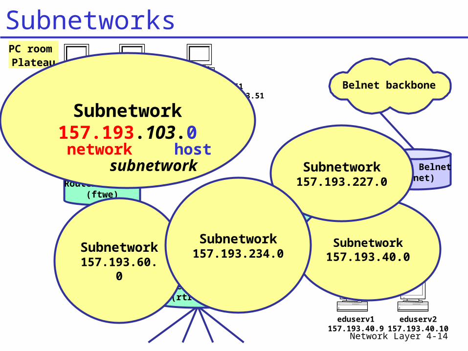
Subnetwork157.193.40.0
Subnetwork157.193.227.
0
Subnetwork
157.193.60.0
Subnetwork157.193.234.
0
Subnetwork157.193.103.0network
subnetworkhost
Subnetworks
Network Layer 4-15
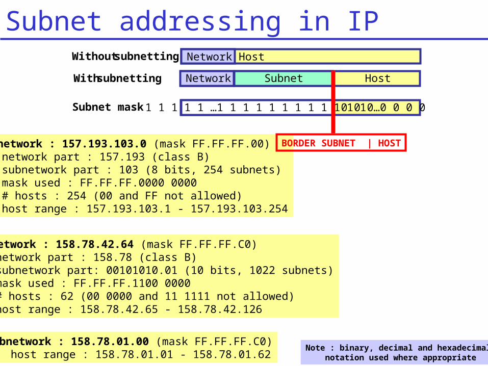
0 0 0 0…0 0 0 0
HostWith subnetting Network Subnet
Subnet mask 1 1 1 1 1 …1 1 1 1 1 1 1 1 1 1 1 1
Subnetwork : 157.193.103.0 (mask FF.FF.FF.00)network part : 157.193 (class B)subnetwork part : 103 (8 bits, 254 subnets)mask used : FF.FF.FF.0000 0000# hosts : 254 (00 and FF not allowed)host range : 157.193.103.1 - 157.193.103.254
Subnetwork : 158.78.42.64 (mask FF.FF.FF.C0)network part : 158.78 (class B)subnetwork part: 00101010.01 (10 bits, 1022 subnets)mask used : FF.FF.FF.1100 0000# hosts : 62 (00 0000 and 11 1111 not allowed)host range : 158.78.42.65 - 158.78.42.126
Note : binary, decimal and hexadecimal notation used where appropriate
Subnetwork : 158.78.01.00 (mask FF.FF.FF.C0)host range : 158.78.01.01 - 158.78.01.62
Without subnetting HostNetwork
BORDER SUBNET | HOST
Subnet addressing in IP
Network Layer 4-16
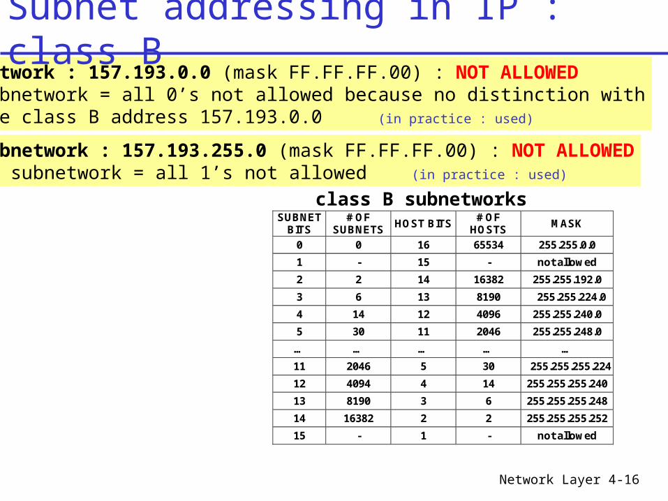
Subnetwork : 157.193.0.0 (mask FF.FF.FF.00) : NOT ALLOWEDsubnetwork = all 0’s not allowed because no distinction withthe class B address 157.193.0.0 (in practice : used)
Subnetwork : 157.193.255.0 (mask FF.FF.FF.00) : NOT ALLOWEDsubnetwork = all 1’s not allowed (in practice : used)
SUBNET BITS
# OF SUBNETS
HOST BITS # OF
HOSTS MASK
0 0 16 65534 255.255.0.0
1 - 15 - not allowed
2 2 14 16382 255.255.192.0
3 6 13 8190 255.255.224.0
4 14 12 4096 255.255.240.0
5 30 11 2046 255.255.248.0
… … … … …
11 2046 5 30 255.255.255.224
12 4094 4 14 255.255.255.240
13 8190 3 6 255.255.255.248
14 16382 2 2 255.255.255.252
15 - 1 - not allowed
class B subnetworks
Subnet addressing in IP : class B
Network Layer 4-17
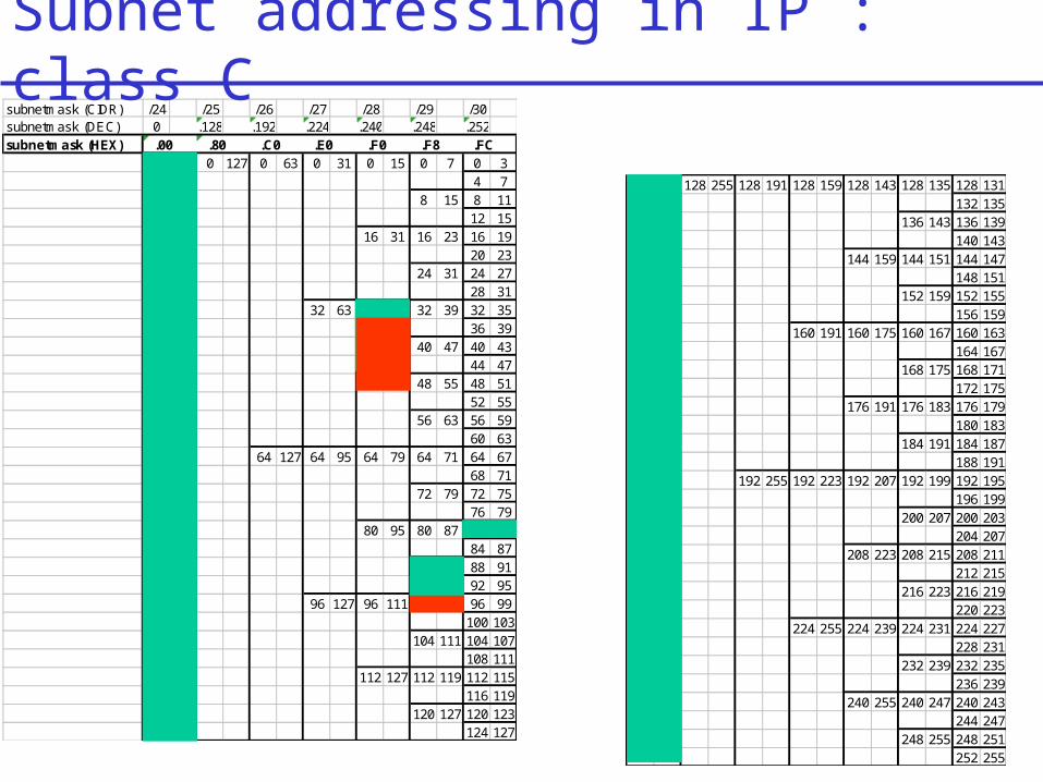
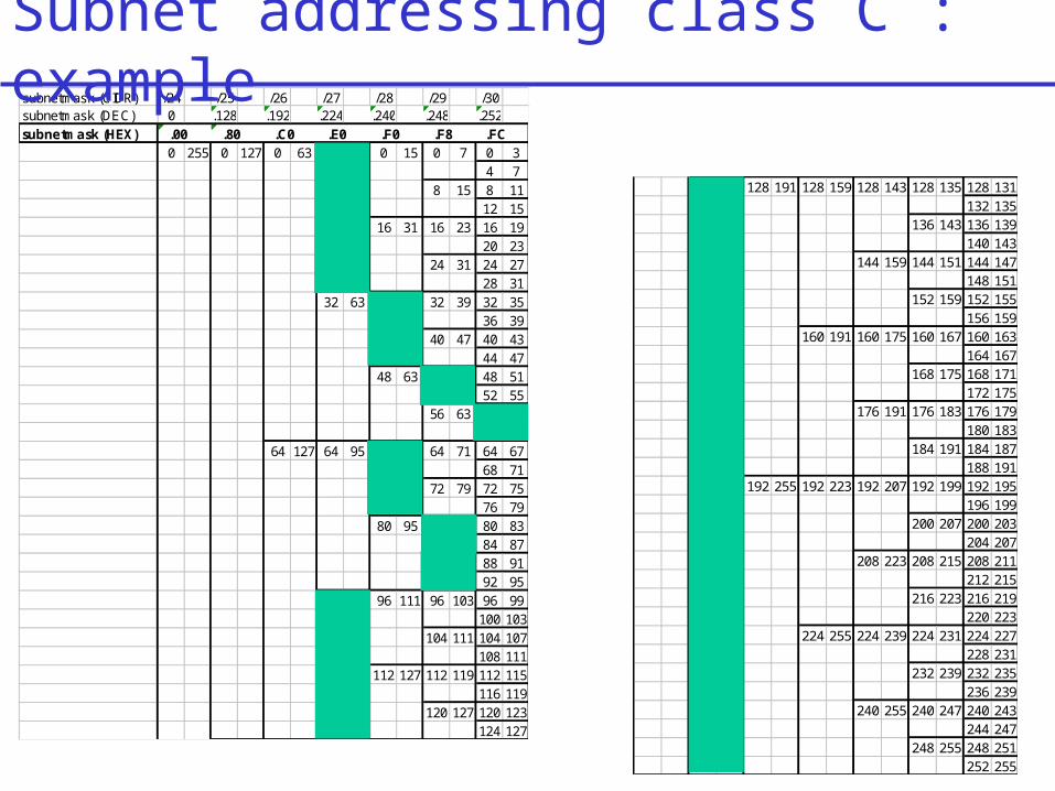
subnetmask (CIDR) /24 /25 /26 /27 /28 /29 /30subnetmask (DEC) 0 .128 .192 .224 .240 .248 .252subnetmask (HEX) .00 .80 .C0 .E0 .F0 .F8 .FC
0 255 0 127 0 63 0 31 0 15 0 7 0 34 7
8 15 8 1112 15
16 31 16 23 16 1920 23
24 31 24 2728 31
32 63 32 47 32 39 32 3536 39
40 47 40 4344 47
48 63 48 55 48 5152 55
56 63 56 5960 63
64 127 64 95 64 79 64 71 64 6768 71
72 79 72 7576 79
80 95 80 87 80 8384 87
88 95 88 9192 95
96 127 96 111 96 103 96 99100 103
104 111 104 107108 111
112 127 112 119 112 115116 119
120 127 120 123124 127
128 255 128 191 128 159 128 143 128 135 128 131132 135
136 143 136 139140 143
144 159 144 151 144 147148 151
152 159 152 155156 159
160 191 160 175 160 167 160 163164 167
168 175 168 171172 175
176 191 176 183 176 179180 183
184 191 184 187188 191
192 255 192 223 192 207 192 199 192 195196 199
200 207 200 203204 207
208 223 208 215 208 211212 215
216 223 216 219220 223
224 255 224 239 224 231 224 227228 231
232 239 232 235236 239
240 255 240 247 240 243244 247
248 255 248 251252 255
Subnet addressing in IP : class C
Network Layer 4-18
subnetmask (CIDR) /24 /25 /26 /27 /28 /29 /30subnetmask (DEC) 0 .128 .192 .224 .240 .248 .252subnetmask (HEX) .00 .80 .C0 .E0 .F0 .F8 .FC
0 255 0 127 0 63 0 31 0 15 0 7 0 34 7
8 15 8 1112 15
16 31 16 23 16 1920 23
24 31 24 2728 31
32 63 32 47 32 39 32 3536 39
40 47 40 4344 47
48 63 48 55 48 5152 55
56 63 56 5960 63
64 127 64 95 64 79 64 71 64 6768 71
72 79 72 7576 79
80 95 80 87 80 8384 87
88 95 88 9192 95
96 127 96 111 96 103 96 99100 103
104 111 104 107108 111
112 127 112 119 112 115116 119
120 127 120 123124 127
128 255 128 191 128 159 128 143 128 135 128 131132 135
136 143 136 139140 143
144 159 144 151 144 147148 151
152 159 152 155156 159
160 191 160 175 160 167 160 163164 167
168 175 168 171172 175
176 191 176 183 176 179180 183
184 191 184 187188 191
192 255 192 223 192 207 192 199 192 195196 199
200 207 200 203204 207
208 223 208 215 208 211212 215
216 223 216 219220 223
224 255 224 239 224 231 224 227228 231
232 239 232 235236 239
240 255 240 247 240 243244 247
248 255 248 251252 255
Subnet addressing class C : example
Network Layer 4-19
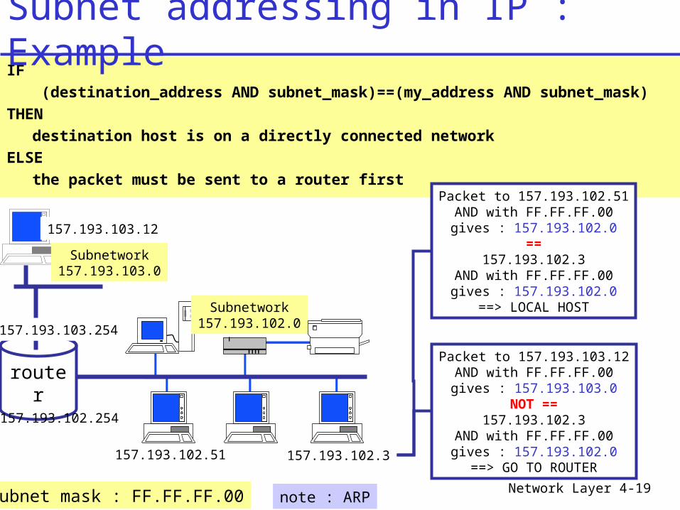
IF
(destination_address AND subnet_mask)==(my_address AND subnet_mask)
THEN
destination host is on a directly connected network
ELSE
the packet must be sent to a router firstPacket to 157.193.102.51
AND with FF.FF.FF.00gives : 157.193.102.0
==157.193.102.3
AND with FF.FF.FF.00gives : 157.193.102.0
==> LOCAL HOST
Packet to 157.193.103.12AND with FF.FF.FF.00gives : 157.193.103.0
NOT ==157.193.102.3
AND with FF.FF.FF.00gives : 157.193.102.0==> GO TO ROUTER
router
157.193.102.3
157.193.102.254
157.193.102.51
Subnetwork157.193.102.0
157.193.103.12
157.193.103.254
Subnetwork157.193.103.0
subnet mask : FF.FF.FF.00 note : ARP
Subnet addressing in IP : Example
Network Layer 4-20
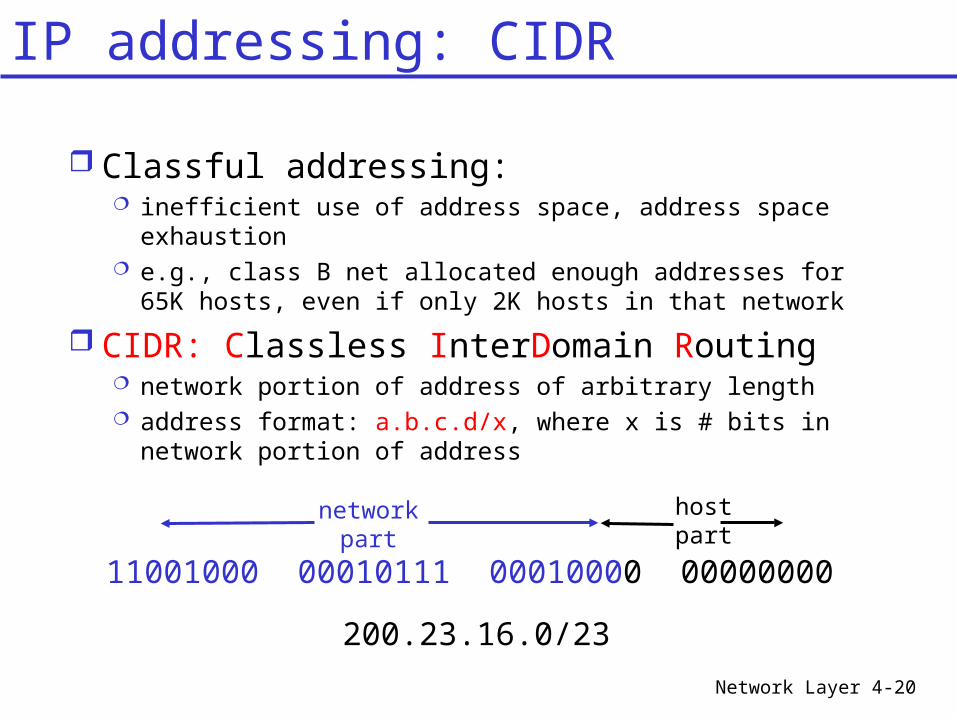
Classful addressing: inefficient use of address space, address space
exhaustion e.g., class B net allocated enough addresses for 65K
hosts, even if only 2K hosts in that network
CIDR: Classless InterDomain Routing network portion of address of arbitrary length address format: a.b.c.d/x, where x is # bits in network
portion of address
11001000 00010111 00010000 00000000
networkpart
hostpart
200.23.16.0/23
IP addressing: CIDR
Network Layer 4-21
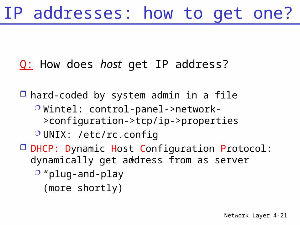
Q: How does host get IP address?
hard-coded by system admin in a file Wintel: control-panel->network-
>configuration->tcp/ip->properties UNIX: /etc/rc.config
DHCP: Dynamic Host Configuration Protocol: dynamically get address from as server “plug-and-play”
(more shortly)
IP addresses: how to get one?
Network Layer 4-22
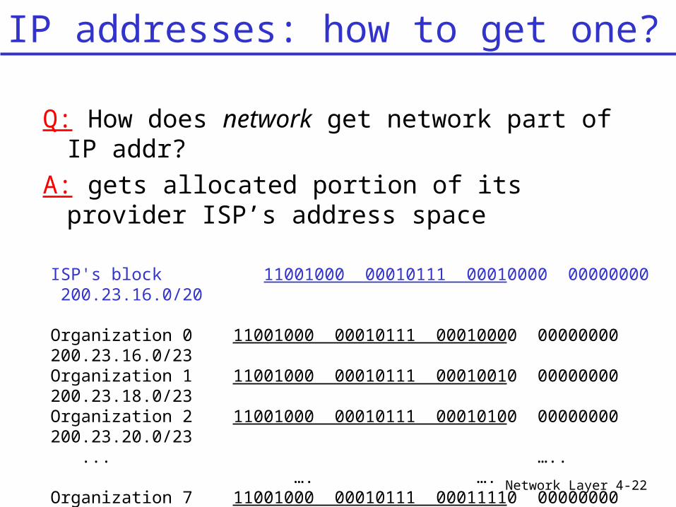
Q: How does network get network part of IP addr?
A: gets allocated portion of its provider ISP’s address space
ISP's block 11001000 00010111 00010000 00000000 200.23.16.0/20
Organization 0 11001000 00010111 00010000 00000000 200.23.16.0/23 Organization 1 11001000 00010111 00010010 00000000 200.23.18.0/23 Organization 2 11001000 00010111 00010100 00000000 200.23.20.0/23 ... ….. …. ….
Organization 7 11001000 00010111 00011110 00000000 200.23.30.0/23
IP addresses: how to get one?
Network Layer 4-23
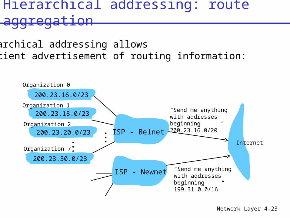
“Send me anythingwith addresses beginning 200.23.16.0/20”
200.23.16.0/23
200.23.18.0/23
200.23.30.0/23
ISP - Belnet
Organization 0
Organization 7Internet
Organization 1
ISP - Newnet “Send me anythingwith addresses beginning 199.31.0.0/16”
200.23.20.0/23Organization 2
...
...
Hierarchical addressing allows efficient advertisement of routing information:
Hierarchical addressing: route aggregation
Network Layer 4-24
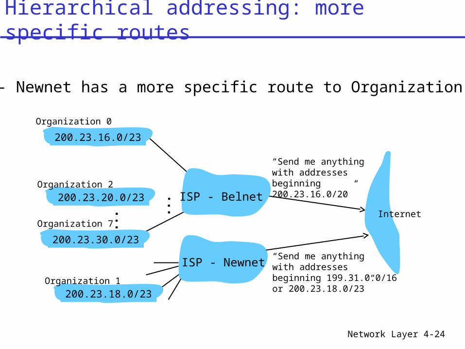
ISPs - Newnet has a more specific route to Organization 1
“Send me anythingwith addresses beginning 200.23.16.0/20”
200.23.16.0/23
200.23.18.0/23
200.23.30.0/23
ISP - Belnet
Organization 0
Organization 7Internet
Organization 1
ISP - Newnet“Send me anythingwith addresses beginning 199.31.0.0/16or 200.23.18.0/23”
200.23.20.0/23Organization 2
...
...
Hierarchical addressing: more specific routes
Network Layer 4-25
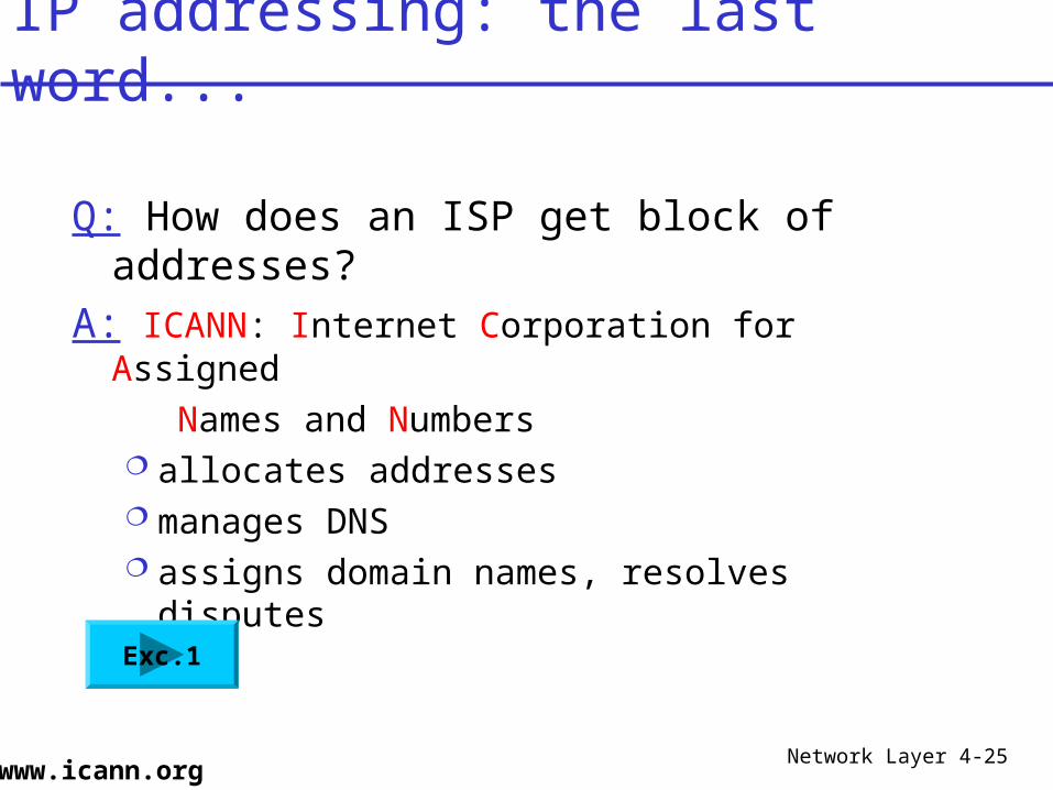
Q: How does an ISP get block of addresses?
A: ICANN: Internet Corporation for Assigned
Names and Numbers allocates addresses manages DNS assigns domain names, resolves disputes
IP addressing: the last word...
www.icann.org
Exc.1
Network Layer 4-26
Chapter 4 outline
4.4 The Internet (IP) Protocol 4.4.1 IPv4 addressing 4.4.2 Moving a datagram from
source to destination : forwarding 4.4.3 Datagram format 4.4.4 IP fragmentation 4.4.5 ICMP: Internet Control Message
Protocol 4.4.6 DHCP: Dynamic Host Configuration
Protocol 4.4.7 NAT: Network Address Translation
Network Layer 4-27
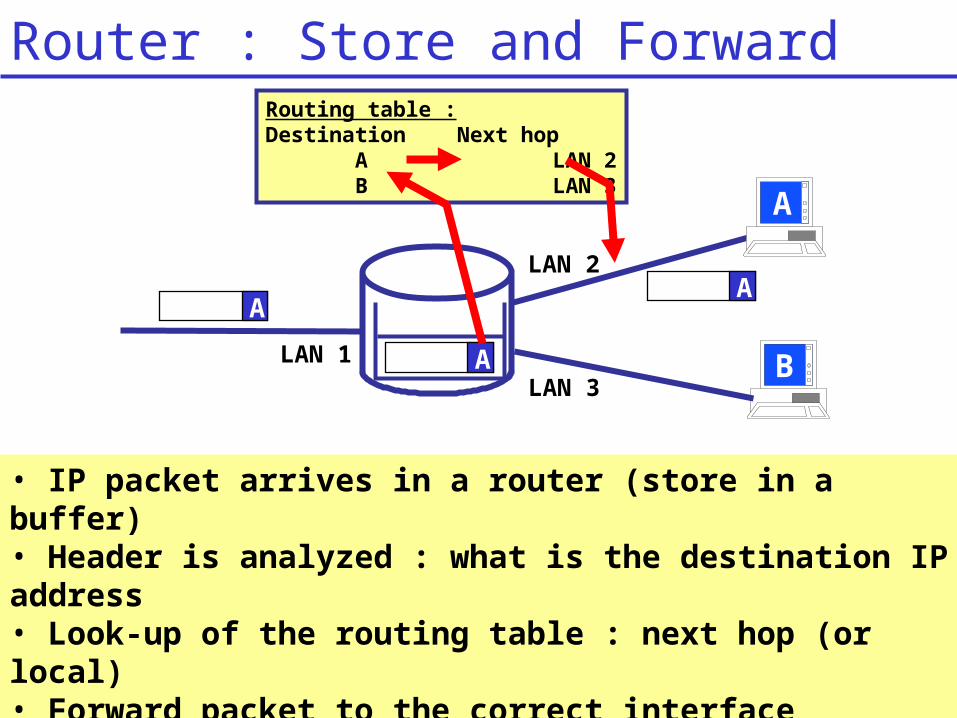
• IP packet arrives in a router (store in a buffer)• Header is analyzed : what is the destination IP address• Look-up of the routing table : next hop (or local)• Forward packet to the correct interface
(or deliver to local application)
Routing table : Destination Next hop A LAN 2 B LAN 3
A
AA
LAN 1
LAN 2
LAN 3
A
B
Router : Store and Forward
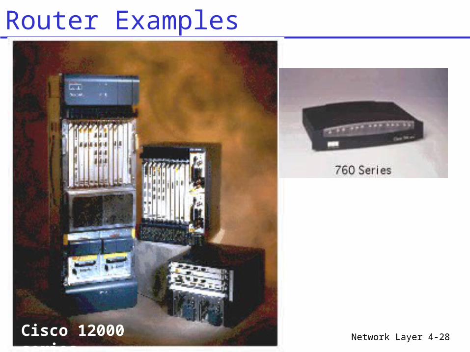
Network Layer 4-28Cisco 12000 series
Router Examples
Network Layer 4-29
router A
LAN 2
Subnetwork157.193.103.0
157.193.102.254
157.193.103.254
157.193.104.254
157.193.102.253
LAN 1
Subnetwork157.193.102.0
157.193.102.1
157.193.103.1
157.193.104.1
157.193.102.34
Routing table router A
router B
INTERNET
LA
N 3
Subnetwork157.193.104.0
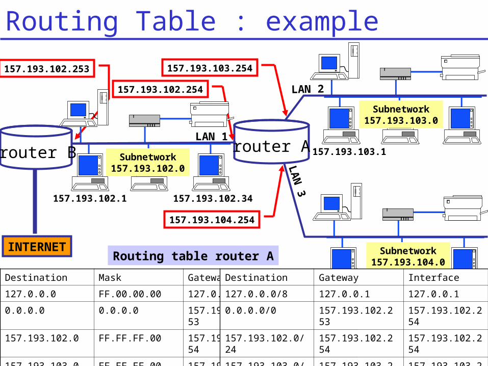
Destination Mask Gateway Interface
127.0.0.0 FF.00.00.00 127.0.0.1 Lo0
0.0.0.0 0.0.0.0 157.193.102.253
LAN 1
157.193.102.0 FF.FF.FF.00 157.193.102.254
LAN 1
157.193.103.0 FF.FF.FF.00 157.193.103.254
LAN 2
157.193.104.0 FF.FF.FF.00 157.193.104.254
LAN 3
Destination Gateway Interface
127.0.0.0/8 127.0.0.1 127.0.0.1
0.0.0.0/0 157.193.102.253
157.193.102.254
157.193.102.0/24
157.193.102.254
157.193.102.254
157.193.103.0/24
157.193.103.254
157.193.103.254
157.193.104.0/24
157.193.104.254
157.193.104.254
Routing Table : example
Network Layer 4-30
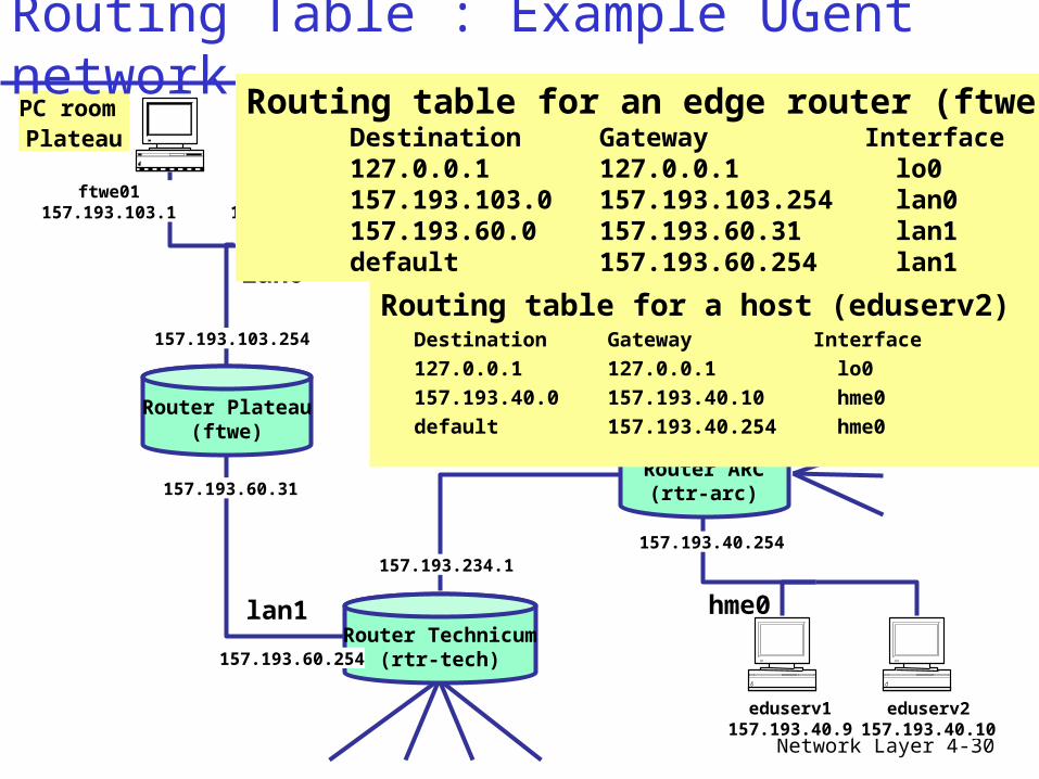
Router Plateau(ftwe)
157.193.103.254
eduserv2157.193.40.10
eduserv1157.193.40.9
157.193.40.254
157.193.227.1
Router Belnet(belnet)
157.193.227.2
Router ARC(rtr-arc)
157.193.234.2
157.193.234.1
Router Technicum(rtr-tech)157.193.60.254
157.193.60.31
ftwe01157.193.103.1
ftwe02 157.193.103.2
ftwe51 157.193.103.51
PC room Plateau
Belnet backbone
lan0
lan1 hme0
Routing table for a host (eduserv2)Destination Gateway Interface
127.0.0.1 127.0.0.1 lo0
157.193.40.0 157.193.40.10 hme0
default 157.193.40.254 hme0
Routing table for an edge router (ftwe)Destination Gateway Interface127.0.0.1 127.0.0.1 lo0157.193.103.0 157.193.103.254 lan0157.193.60.0 157.193.60.31 lan1default 157.193.60.254 lan1
Routing Table : Example UGent network
Network Layer 4-31
allserv:/staff/ftwe/pdemeest$ netstat -rn
Routing Table: Destination Gateway Flags Ref Use Interface-------------------- -------------------- ----- ----- ------ ---------157.193.40.0 157.193.40.42 U 3 63929 hme0224.0.0.0 157.193.40.42 U 3 0 hme0default 157.193.40.254 UG 028820629127.0.0.1 127.0.0.1 UH 07349737 lo0
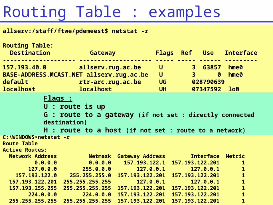
allserv:/staff/ftwe/pdemeest$ netstat -r
Routing Table: Destination Gateway Flags Ref Use Interface-------------------- -------------------- ----- ----- ------ ---------157.193.40.0 allserv.rug.ac.be U 3 63857 hme0BASE-ADDRESS.MCAST.NET allserv.rug.ac.be U 3 0 hme0default rtr-arc.rug.ac.be UG 028790639localhost localhost UH 07347592 lo0
C:\WINDOWS>netstat -rRoute TableActive Routes: Network Address Netmask Gateway Address Interface Metric 0.0.0.0 0.0.0.0 157.193.122.1 157.193.122.201 1 127.0.0.0 255.0.0.0 127.0.0.1 127.0.0.1 1 157.193.122.0 255.255.255.0 157.193.122.201 157.193.122.201 1 157.193.122.201 255.255.255.255 127.0.0.1 127.0.0.1 1 157.193.255.255 255.255.255.255 157.193.122.201 157.193.122.201 1 224.0.0.0 224.0.0.0 157.193.122.201 157.193.122.201 1 255.255.255.255 255.255.255.255 157.193.122.201 157.193.122.201 1
Flags : U : route is upG : route to a gateway (if not set : directly connected destination)H : route to a host (if not set : route to a network)
Routing Table : examples
Network Layer 4-32
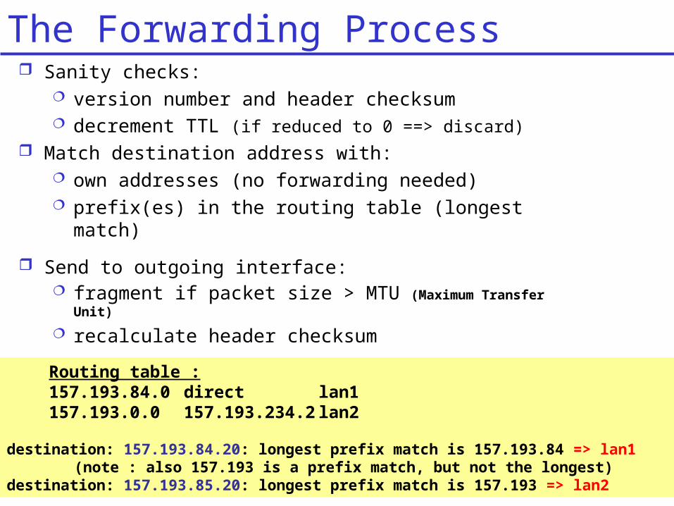
Sanity checks: version number and header checksum decrement TTL (if reduced to 0 ==> discard)
Match destination address with: own addresses (no forwarding needed) prefix(es) in the routing table (longest match)
Routing table : 157.193.84.0 direct lan1157.193.0.0 157.193.234.2 lan2
destination: 157.193.84.20: longest prefix match is 157.193.84 => lan1(note : also 157.193 is a prefix match, but not the longest)
destination: 157.193.85.20: longest prefix match is 157.193 => lan2
Send to outgoing interface: fragment if packet size > MTU (Maximum Transfer Unit)
recalculate header checksum
The Forwarding Process
Network Layer
R1
R2R4
R3
UK Backbone
Dutch Backbone
Belgian BackboneBELNET
193.190.19x.0
KULeuvenBackbone134.58.0.0
UGent BackboneRUGNET
157.193.0.0
GermanBackbone
French Backbone
European BackboneTransatlantic
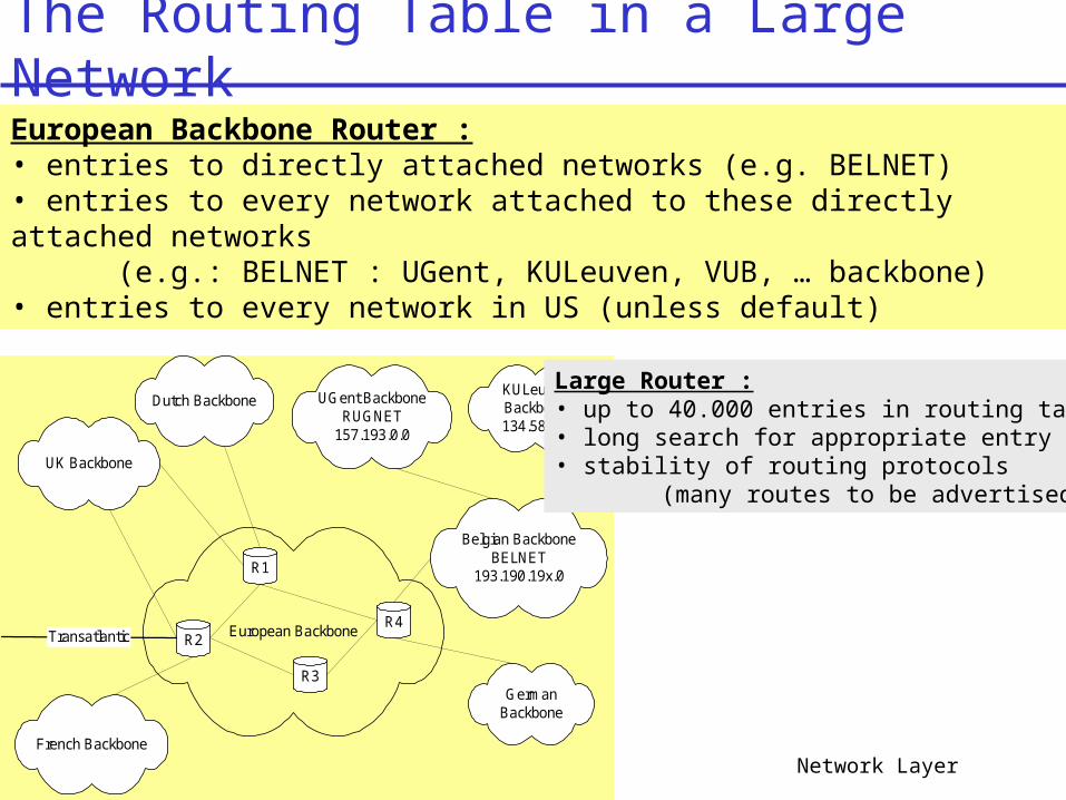
European Backbone Router : • entries to directly attached networks (e.g. BELNET)• entries to every network attached to these directly attached networks
(e.g.: BELNET : UGent, KULeuven, VUB, … backbone)• entries to every network in US (unless default)
Large Router : • up to 40.000 entries in routing table• long search for appropriate entry• stability of routing protocols
(many routes to be advertised)
The Routing Table in a Large Network
Network Layer 4-34
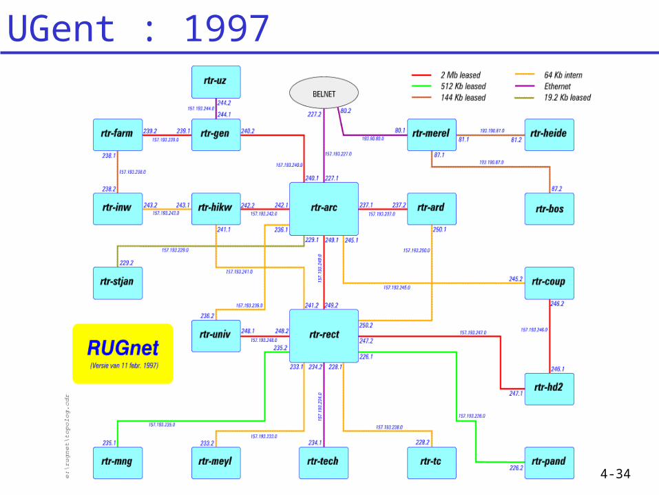
UGent : 1997
Network Layer 4-35
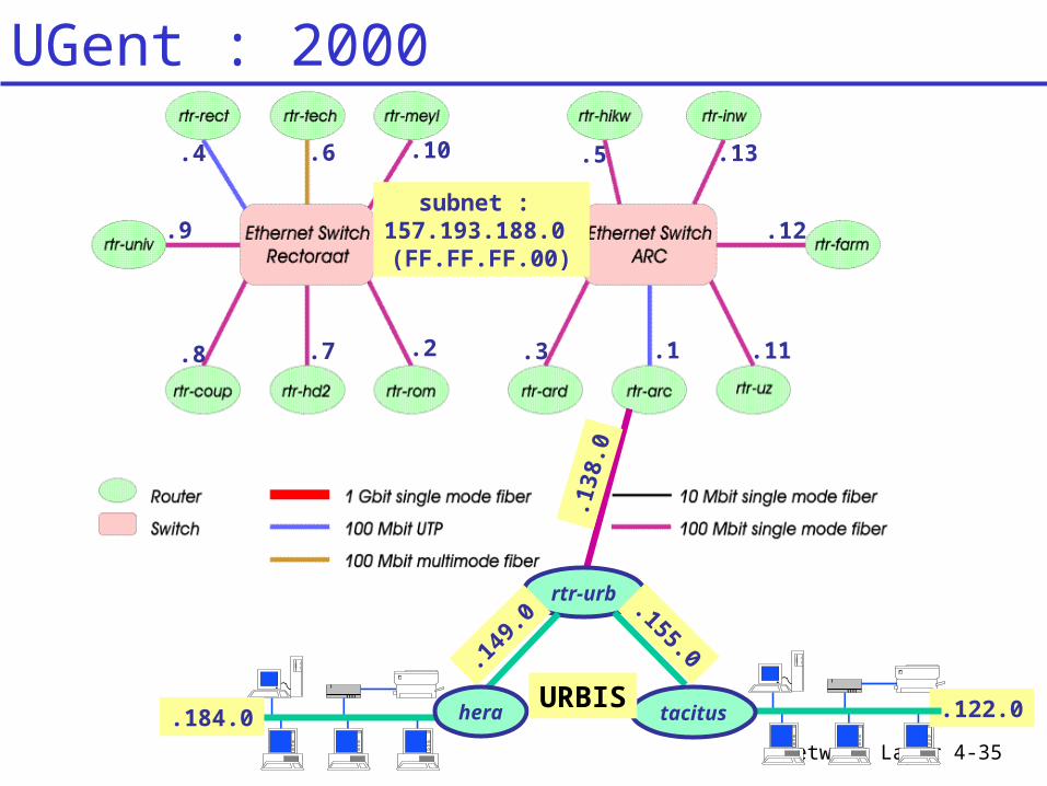
subnet : 157.193.188.0 (FF.FF.FF.00)
.6
.1.2 .3
.4 .5
.7.8
.9
.10
.11
.12
.13
.122.0.184.0
.138
.0rtr-urb
.155.0.149
.0
tacitusheraURBIS
UGent : 2000
Network Layer 4-36
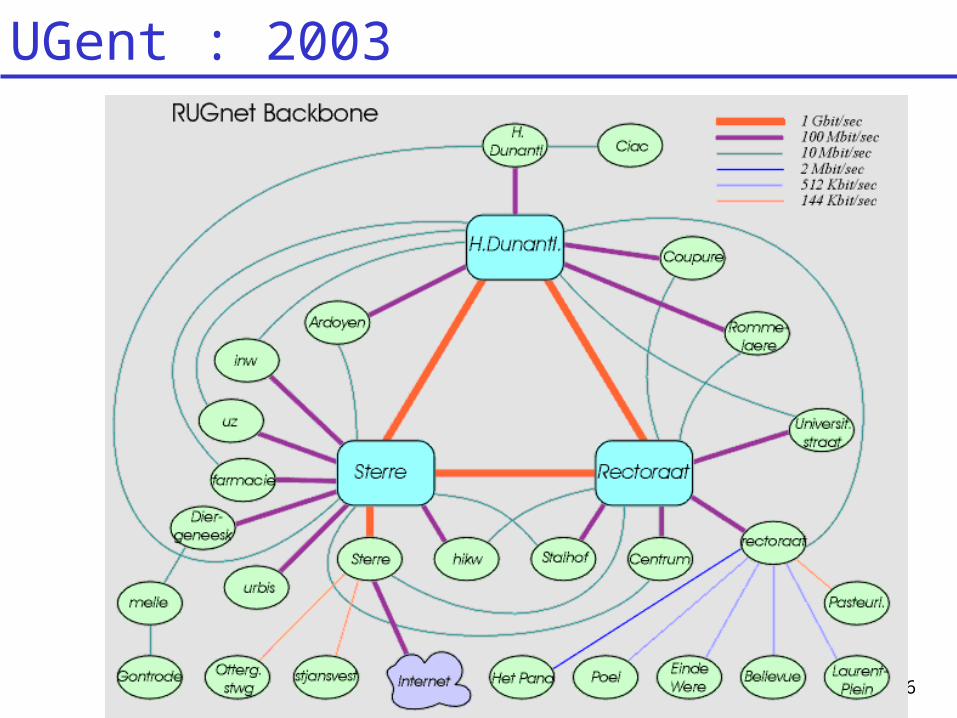
UGent : 2003
Network Layer 4-37
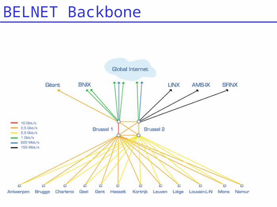
BELNET Backbone
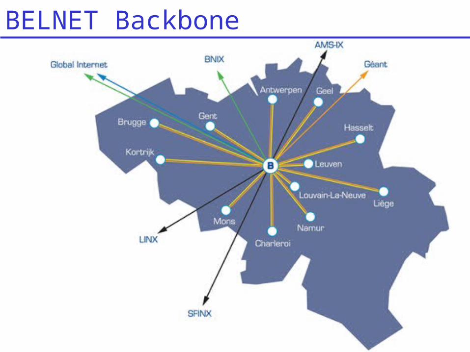
Network Layer 4-38
BELNET Backbone
Network Layer 4-39
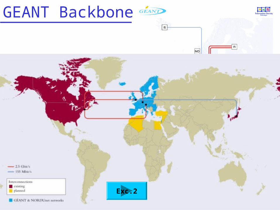
GEANT Backbone
Exc.2
Network Layer 4-40
4.4 The Internet (IP) Protocol 4.4.1 IPv4 addressing 4.4.2 Moving a datagram from source to
destination 4.4.3 Datagram format 4.4.4 IP fragmentation 4.4.5 ICMP: Internet Control Message
Protocol 4.4.6 DHCP: Dynamic Host Configuration
Protocol 4.4.7 NAT: Network Address Translation
Chapter 4 outline
Network Layer 4-41
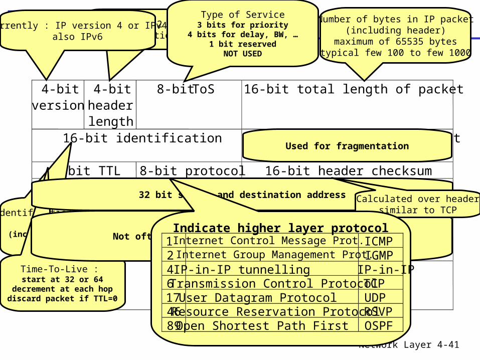
IP Packet Format
4-bitversion
4-bitheaderlength
8-bit ToS 16-bit total length of packet
16-bit identification 3-bit flags 13-bit fragmentoffset
8-bit TTL 8-bit protocol 16-bit header checksum32-bit source IP address
32-bit destination IP address
Options (if any)
Data
Identification of each packetsend by host
(increment each time packet is sent)
Used for fragmentation
Time-To-Live : start at 32 or 64
decrement at each hopdiscard packet if TTL=0
32 bit source and destination address
Not often used (timestamp, route to follow, …)
Calculated over headersimilar to TCP
Indicate higher layer protocol1 Internet Control Message Prot. ICMP2 Internet Group Management Prot.IGMP4 IP-in-IP tunnelling IP-in-IP6 Transmission Control ProtocolTCP17 User Datagram Protocol UDP46 Resource Reservation ProtocolRSVP89 Open Shortest Path First OSPF
Number of 32 bit words(if no options : 5)
Number of bytes in IP packet(including header)
maximum of 65535 bytestypical few 100 to few 1000
Type of Service3 bits for priority
4 bits for delay, BW, …1 bit reserved
NOT USED
Currently : IP version 4 or IPv4also IPv6
Network Layer 4-42
Chapter 4 outline
4.4 The Internet (IP) Protocol 4.4.1 IPv4 addressing 4.4.2 Moving a datagram from source to
destination 4.4.3 Datagram format 4.4.4 IP fragmentation 4.4.5 ICMP: Internet Control Message
Protocol 4.4.6 DHCP: Dynamic Host Configuration
Protocol 4.4.7 NAT: Network Address Translation
Network Layer 4-43
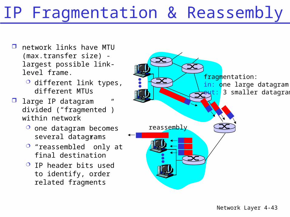
network links have MTU (max.transfer size) - largest possible link-level frame. different link types,
different MTUs large IP datagram divided
(“fragmented”) within network one datagram becomes
several datagrams “reassembled” only at
final destination IP header bits used to
identify, order related fragments
fragmentation: in: one large datagramout: 3 smaller datagrams
reassembly
IP Fragmentation & Reassembly
Network Layer 4-44
ID=x
offset=0
fragflag=0
length=4000
ID=x
offset=0
fragflag=1
length=1500
ID=x
offset=1480
fragflag=1
length=1500
ID=x
offset=2960
fragflag=0
length=1040
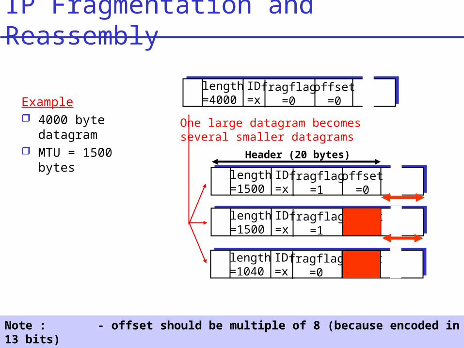
One large datagram becomesseveral smaller datagrams
Example 4000 byte
datagram MTU = 1500 bytes
Note : - offset should be multiple of 8 (because encoded in 13 bits)- for offset : do not take header into account
IP Fragmentation and Reassembly
Header (20 bytes)

Network Layer 4-45
Chapter 4 outline
4.4 The Internet (IP) Protocol 4.4.1 IPv4 addressing 4.4.2 Moving a datagram from source to
destination 4.4.3 Datagram format 4.4.4 IP fragmentation 4.4.5 ICMP: Internet Control
Message Protocol 4.4.6 DHCP: Dynamic Host Configuration
Protocol 4.4.7 NAT: Network Address Translation
Network Layer 4-46
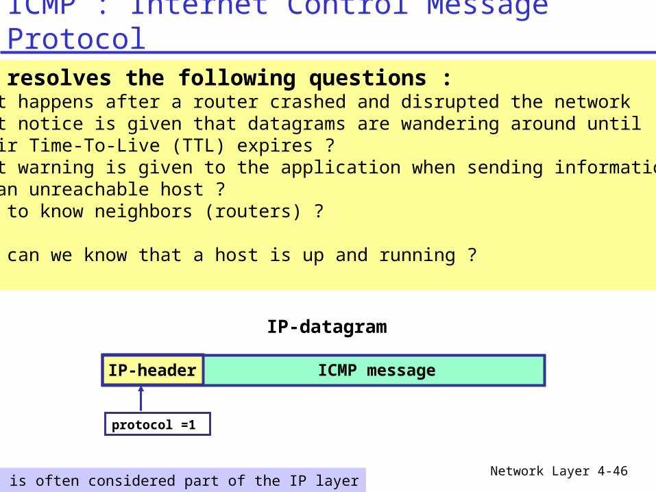
ICMP : Internet Control Message Protocol
ICMP resolves the following questions : • What happens after a router crashed and disrupted the network• What notice is given that datagrams are wandering around until their Time-To-Live (TTL) expires ?• What warning is given to the application when sending information to an unreachable host ?• How to know neighbors (routers) ?• ...• How can we know that a host is up and running ?• ...
ICMP messageIP-header
IP-datagram
ICMP is often considered part of the IP layer
protocol =1
Network Layer 4-47
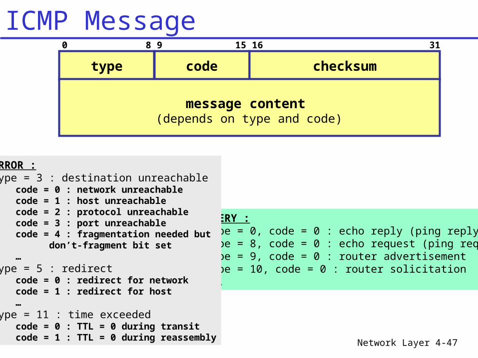
0 8 9 15 16 31
type code checksum
message content (depends on type and code)
QUERY : type = 0, code = 0 : echo reply (ping reply)type = 8, code = 0 : echo request (ping request)type = 9, code = 0 : router advertisementtype = 10, code = 0 : router solicitation...
ERROR : type = 3 : destination unreachable
code = 0 : network unreachablecode = 1 : host unreachablecode = 2 : protocol unreachablecode = 3 : port unreachablecode = 4 : fragmentation needed but don’t-fragment bit set…
type = 5 : redirectcode = 0 : redirect for networkcode = 1 : redirect for host…
type = 11 : time exceededcode = 0 : TTL = 0 during transitcode = 1 : TTL = 0 during reassembly
ICMP Message
Network Layer 4-48
C:\WINDOWS>pingUsage: ping [-t] [-a] [-n count] [-l size] [-f] [-i TTL] [-v TOS] [-r count] [-s count] [[-j host-list] | [-k host-list] [-w timeout] destination-listOptions: -t Ping the specifed host until interrupted. -a Resolve addresses to hostnames. -n count Number of echo requests to send. -l size Send buffer size. -f Set Don't Fragment flag in packet. -i TTL Time To Live. -v TOS Type Of Service. -r count Record route for count hops. -s count Timestamp for count hops. -j host-list Loose source route along host-list. -k host-list Strict source route along host-list. -w timeout Timeout in milliseconds to wait for each reply.
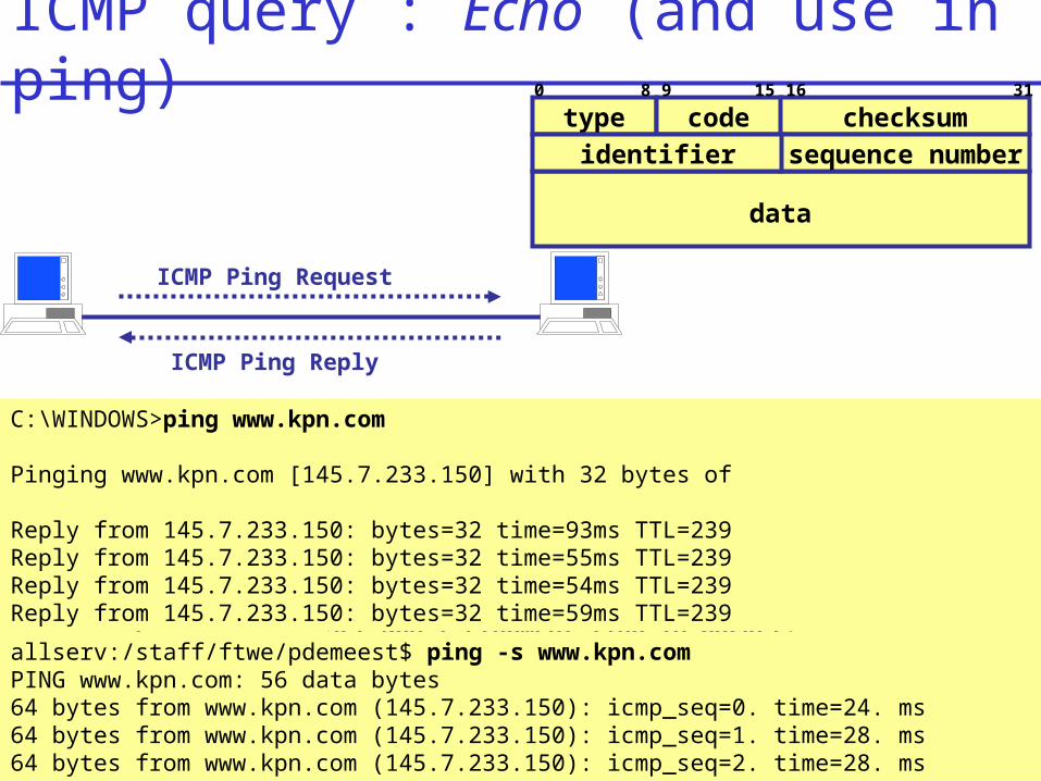
0 8 9 15 16 31
type code checksum
data
sequence numberidentifier
C:\WINDOWS>ping www.kpn.com
Pinging www.kpn.com [145.7.233.150] with 32 bytes of
Reply from 145.7.233.150: bytes=32 time=93ms TTL=239Reply from 145.7.233.150: bytes=32 time=55ms TTL=239Reply from 145.7.233.150: bytes=32 time=54ms TTL=239Reply from 145.7.233.150: bytes=32 time=59ms TTL=239
allserv:/staff/ftwe/pdemeest$ ping -s www.kpn.comPING www.kpn.com: 56 data bytes64 bytes from www.kpn.com (145.7.233.150): icmp_seq=0. time=24. ms64 bytes from www.kpn.com (145.7.233.150): icmp_seq=1. time=28. ms64 bytes from www.kpn.com (145.7.233.150): icmp_seq=2. time=28. ms
ICMP Ping Request
ICMP Ping Reply
ICMP query : Echo (and use in ping)
Network Layer 4-49
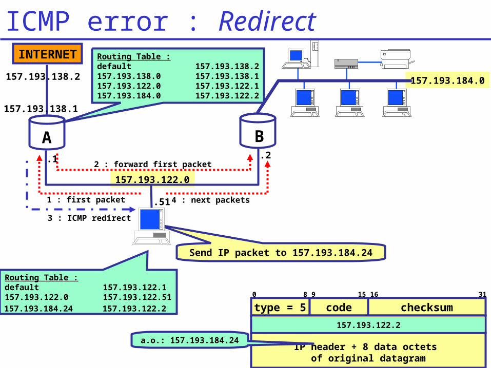
157.193.122.0
0 8 9 15 16 31
type = 5 code checksum
IP header + 8 data octets of original datagram
address of router to be used
1 : first packet
3 : ICMP redirect
2 : forward first packet
4 : next packets
157.193.184.0
.51
.1 .2
Send IP packet to 157.193.184.24
Routing Table :default 157.193.138.2157.193.138.0 157.193.138.1157.193.122.0 157.193.122.1157.193.184.0 157.193.122.2
Routing Table :default 157.193.122.1157.193.122.0 157.193.122.51157.193.184.24 157.193.122.2
157.193.122.2
A B
a.o.: 157.193.184.24
INTERNET
157.193.138.1
157.193.138.2
ICMP error : Redirect
Network Layer 4-50
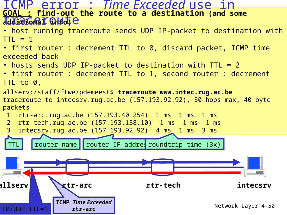
GOAL : find-out the route to a destination (and some additional info)• host running traceroute sends UDP IP-packet to destination with TTL = 1• first router : decrement TTL to 0, discard packet, ICMP time exceeded back• hosts sends UDP IP-packet to destination with TTL = 2• first router : decrement TTL to 1, second router : decrement TTL to 0, discard packet, ICMP time exceeded back• ...allserv:/staff/ftwe/pdemeest$ traceroute www.intec.rug.ac.betraceroute to intecsrv.rug.ac.be (157.193.92.92), 30 hops max, 40 byte packets 1 rtr-arc.rug.ac.be (157.193.40.254) 1 ms 1 ms 1 ms 2 rtr-tech.rug.ac.be (157.193.138.10) 1 ms 1 ms 1 ms 3 intecsrv.rug.ac.be (157.193.92.92) 4 ms 1 ms 3 ms
TTL router name router IP-address roundtrip time (3x)
IP/UDP TTL=1ICMP Time Exceeded
rtr-arc
allserv rtr-arc rtr-tech intecsrv
ICMP error : Time Exceeded use in traceroute
Network Layer 4-51
Chapter 4 outline
4.4 The Internet (IP) Protocol 4.4.1 IPv4 addressing 4.4.2 Moving a datagram from source to destination 4.4.3 Datagram format 4.4.4 IP fragmentation 4.4.5 ICMP: Internet Control Message Protocol 4.4.6 DHCP: Dynamic Host
Configuration Protocol 4.4.7 NAT: Network Address Translation
Network Layer 4-52
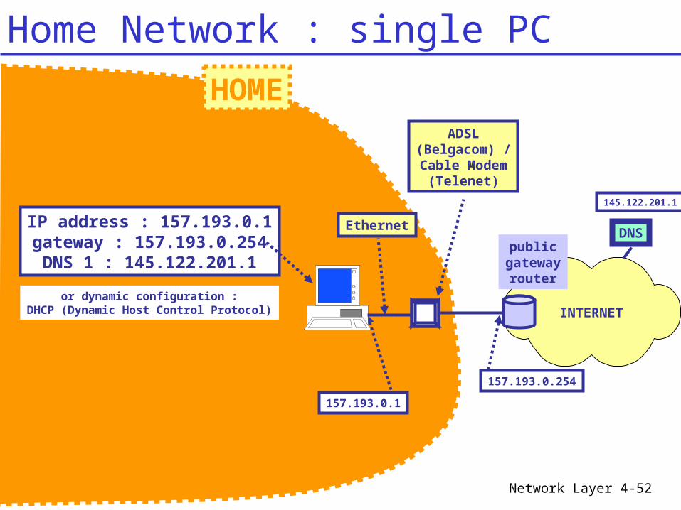
HOME
INTERNET
157.193.0.1
publicgatewayrouter
157.193.0.254
ADSL(Belgacom) /Cable Modem
(Telenet)
IP address : 157.193.0.1gateway : 157.193.0.254DNS 1 : 145.122.201.1
Ethernet DNS
145.122.201.1
or dynamic configuration :DHCP (Dynamic Host Control Protocol)
Home Network : single PC
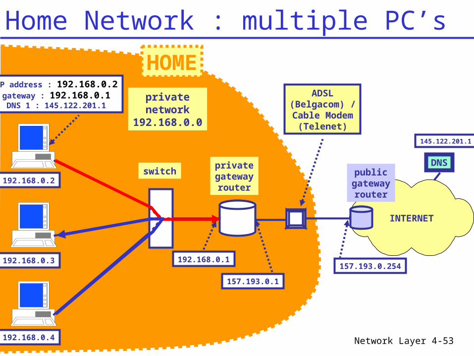
Network Layer 4-53
HOME
INTERNET
publicgatewayrouter
157.193.0.254
ADSL(Belgacom) /Cable Modem
(Telenet)
DNS
145.122.201.1
privatenetwork
192.168.0.0
privategatewayrouter
switch
157.193.0.1
192.168.0.2
192.168.0.3
192.168.0.4
192.168.0.1
IP address : 192.168.0.2gateway : 192.168.0.1DNS 1 : 145.122.201.1
Home Network : multiple PC’s
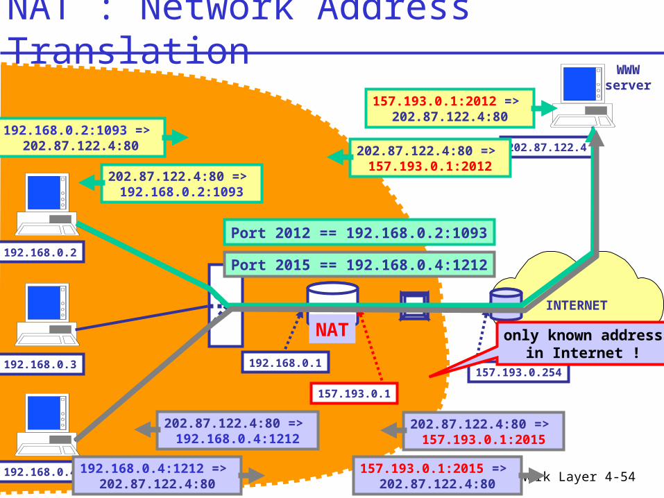
Network Layer 4-54
INTERNET
157.193.0.254
157.193.0.1
192.168.0.2
192.168.0.3
192.168.0.4
192.168.0.1
202.87.122.4
192.168.0.2:1093 => 202.87.122.4:80
157.193.0.1:2012 => 202.87.122.4:80
202.87.122.4:80 => 157.193.0.1:2012
202.87.122.4:80 => 192.168.0.2:1093
Port 2012 == 192.168.0.2:1093
192.168.0.4:1212 => 202.87.122.4:80
157.193.0.1:2015 => 202.87.122.4:80
202.87.122.4:80 => 157.193.0.1:2015
202.87.122.4:80 => 192.168.0.4:1212
Port 2015 == 192.168.0.4:1212
NAT only known addressin Internet !
WWWserver
NAT : Network Address Translation
Network Layer 4-55
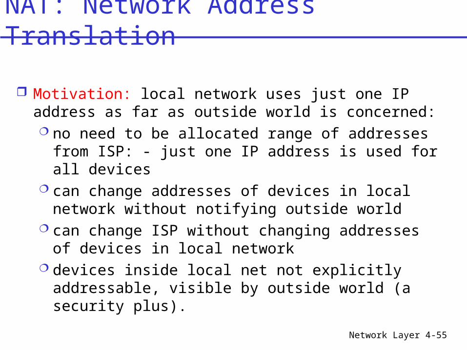
Motivation: local network uses just one IP address as far as outside world is concerned: no need to be allocated range of addresses from
ISP: - just one IP address is used for all devices can change addresses of devices in local network
without notifying outside world can change ISP without changing addresses of
devices in local network devices inside local net not explicitly
addressable, visible by outside world (a security plus).
NAT: Network Address Translation
Network Layer 4-56
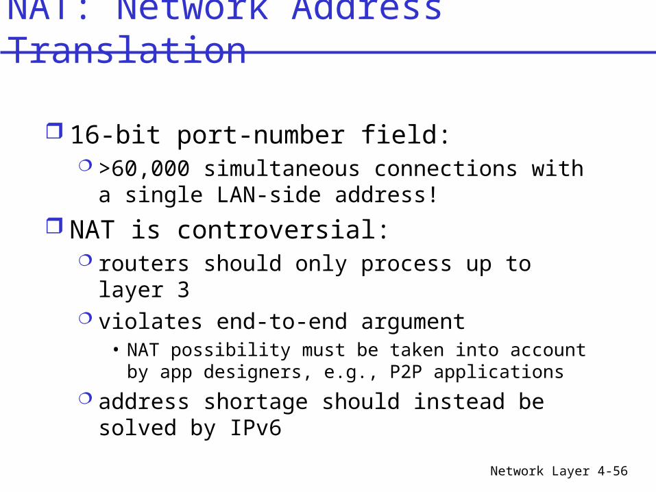
16-bit port-number field: >60,000 simultaneous connections with a
single LAN-side address! NAT is controversial:
routers should only process up to layer 3 violates end-to-end argument
• NAT possibility must be taken into account by app designers, e.g., P2P applications
address shortage should instead be solved by IPv6
NAT: Network Address Translation
Network Layer 4-57
INTERNET
157.193.0.254
157.193.0.1
192.168.0.2
192.168.0.3
192.168.0.4
192.168.0.1
202.87.122.4
NAT
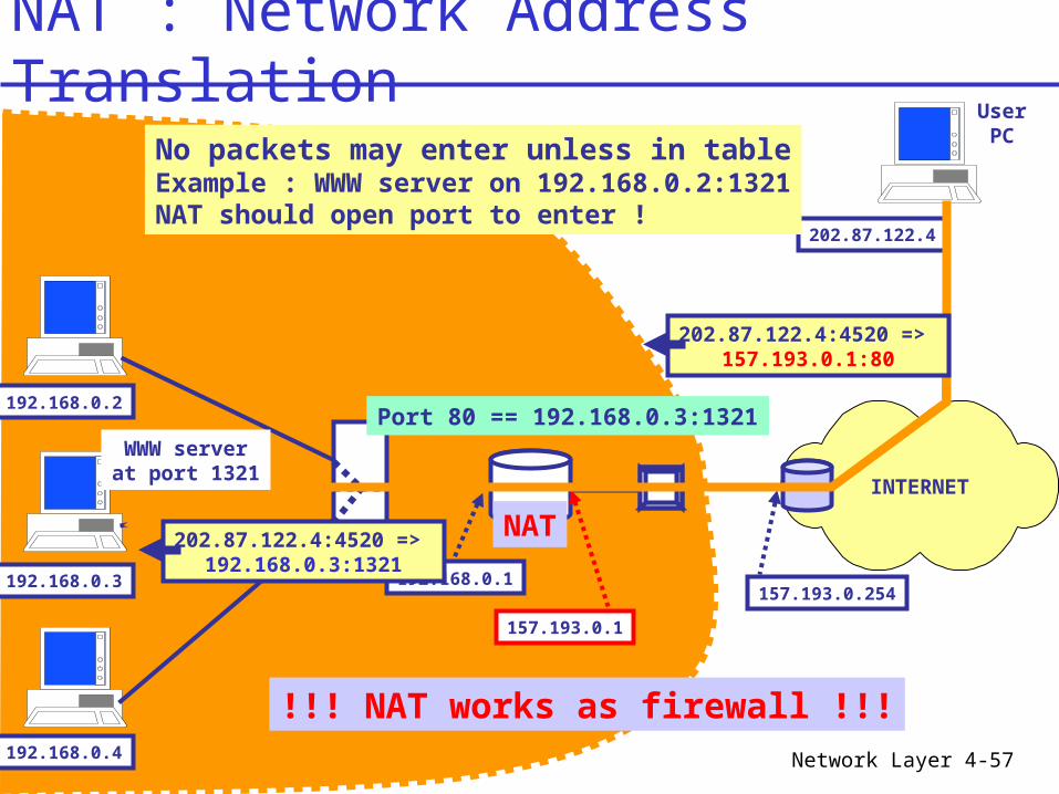
UserPCNo packets may enter unless in table
Example : WWW server on 192.168.0.2:1321NAT should open port to enter !
Port 80 == 192.168.0.3:1321WWW serverat port 1321
!!! NAT works as firewall !!!
202.87.122.4:4520 => 157.193.0.1:80
202.87.122.4:4520 => 192.168.0.3:1321
NAT : Network Address Translation
Network Layer 4-58
INTERNET
157.193.0.254
157.193.0.1
192.168.0.13
192.168.0.23
192.168.0.42
192.168.0.1
DHCPserver
DHCP request
IP : 192.168.0.13gateway : 192.168.0.1DNS : 145.122.201.1
DNS
145.122.201.1
192.168.0.13
192.168.0.23192.168.0.4
2
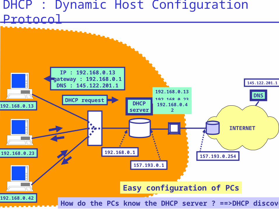
Easy configuration of PCs
How do the PCs know the DHCP server ? ==>DHCP discover
DHCP : Dynamic Host Configuration Protocol
Network Layer 4-59
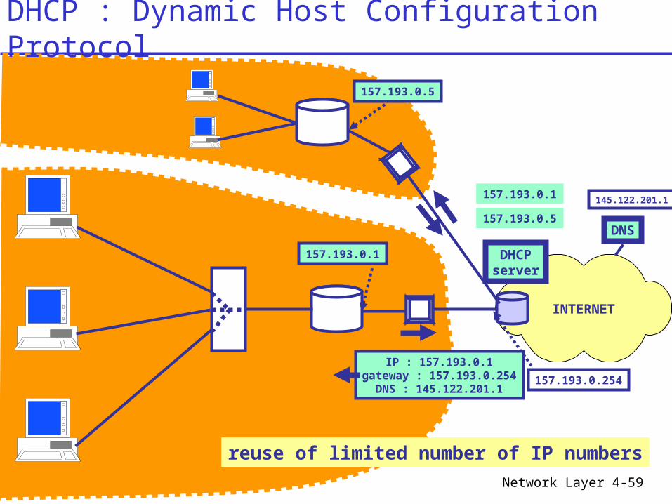
INTERNET
157.193.0.254
157.193.0.1 DHCPserver
DNS
145.122.201.1157.193.0.1
157.193.0.5
IP : 157.193.0.1gateway : 157.193.0.254
DNS : 145.122.201.1
157.193.0.5
reuse of limited number of IP numbers
DHCP : Dynamic Host Configuration Protocol
Network Layer 4-60
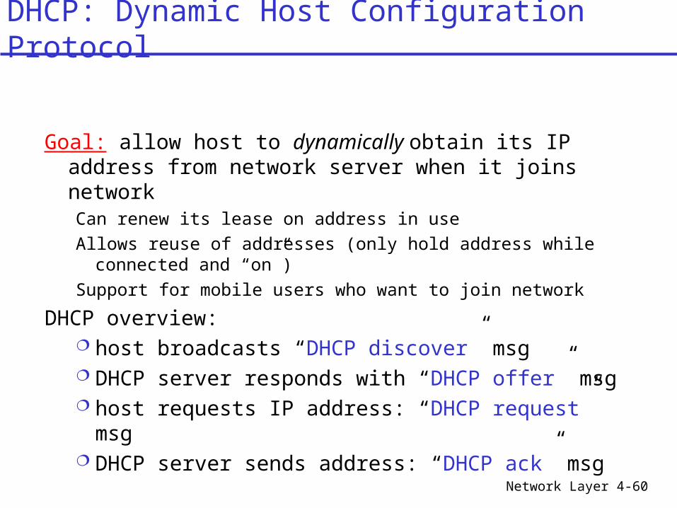
Goal: allow host to dynamically obtain its IP address from network server when it joins networkCan renew its lease on address in useAllows reuse of addresses (only hold address while
connected and “on”)Support for mobile users who want to join network
DHCP overview: host broadcasts “DHCP discover” msg DHCP server responds with “DHCP offer” msg host requests IP address: “DHCP request” msg DHCP server sends address: “DHCP ack” msg
DHCP: Dynamic Host Configuration Protocol
Network Layer 4-61
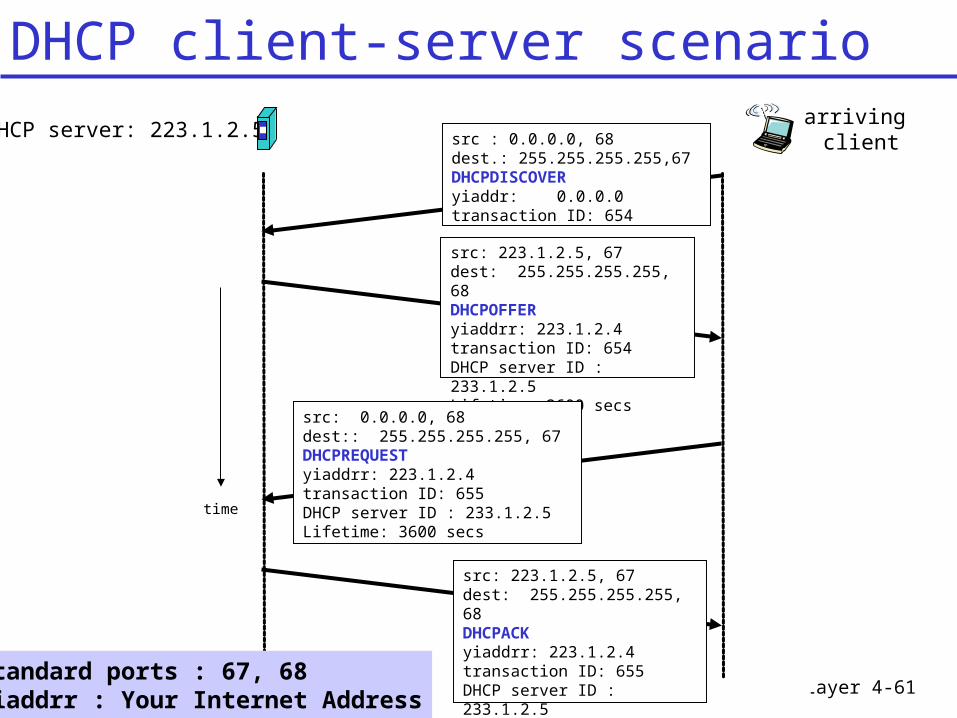
DHCP server: 223.1.2.5arriving client
time
src : 0.0.0.0, 68 dest.: 255.255.255.255,67DHCPDISCOVERyiaddr: 0.0.0.0transaction ID: 654
src: 223.1.2.5, 67 dest: 255.255.255.255, 68DHCPOFFERyiaddrr: 223.1.2.4transaction ID: 654DHCP server ID : 233.1.2.5Lifetime: 3600 secs
src: 0.0.0.0, 68 dest:: 255.255.255.255, 67DHCPREQUESTyiaddrr: 223.1.2.4transaction ID: 655DHCP server ID : 233.1.2.5Lifetime: 3600 secs
src: 223.1.2.5, 67 dest: 255.255.255.255, 68DHCPACKyiaddrr: 223.1.2.4transaction ID: 655DHCP server ID : 233.1.2.5Lifetime: 3600 secs
Standard ports : 67, 68yiaddrr : Your Internet Address
DHCP client-server scenario
Network Layer 4-62
Chapter 4 outline4.1 Introduction and Network Service Models4.2 Routing Principles4.3 Hierarchical Routing4.4 The Internet (IP) Protocol
4.5 Routing in the Internet 4.5.1 Intra-AS routing: RIP and
OSPF 4.5.2 Inter-AS routing: BGP
4.6 What’s Inside a Router?4.7 IPv64.8 Multicast Routing4.9 Mobility
Network Layer 4-63
A B
C
D E
W
X
Y
Y:to B
Destination : Y Forward
RoutingTable ?
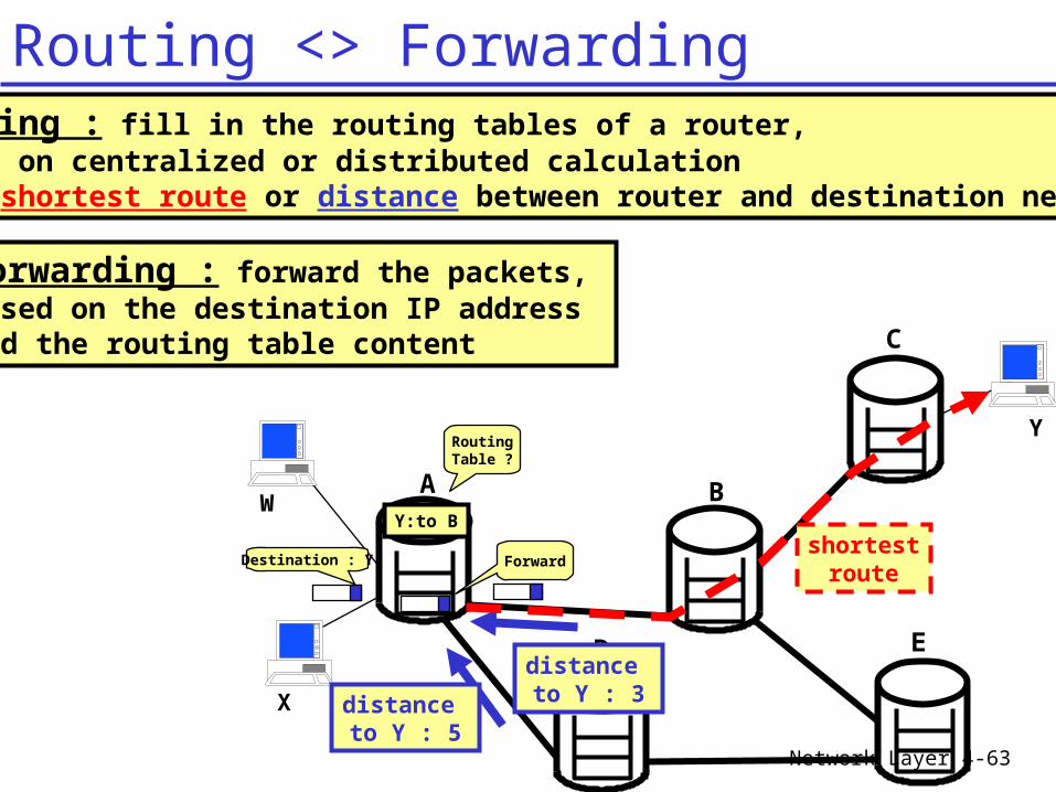
Routing : fill in the routing tables of a router,based on centralized or distributed calculationof a shortest route or distance between router and destination network
Forwarding : forward the packets, based on the destination IP address and the routing table content
distance to Y : 3distance
to Y : 5
shortestroute
Routing <> Forwarding
Network Layer 4-64
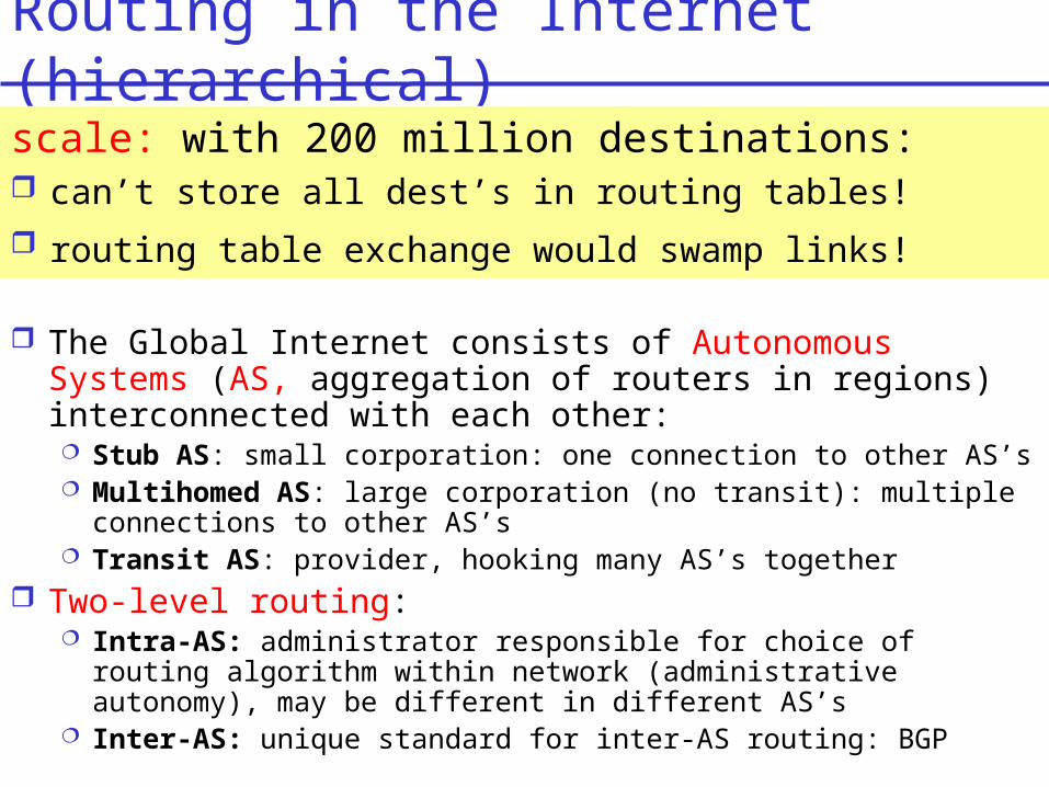
Routing in the Internet (hierarchical)
The Global Internet consists of Autonomous Systems (AS, aggregation of routers in regions) interconnected with each other: Stub AS: small corporation: one connection to other AS’s Multihomed AS: large corporation (no transit): multiple
connections to other AS’s Transit AS: provider, hooking many AS’s together
Two-level routing: Intra-AS: administrator responsible for choice of routing
algorithm within network (administrative autonomy), may be different in different AS’s
Inter-AS: unique standard for inter-AS routing: BGP
scale: with 200 million destinations: can’t store all dest’s in routing tables! routing table exchange would swamp links!
Network Layer 4-65
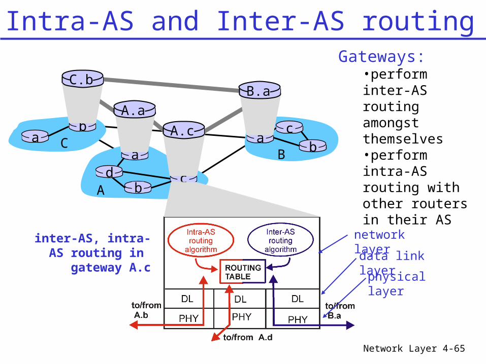
Gateways:•perform inter-AS routing amongst themselves•perform intra-AS routing with other routers in their AS
ab
C
C.b
aB
cb
b
a
Ad c
Intra-AS and Inter-AS routing
A.a
A.c
B.a
inter-AS, intra-AS routing in
gateway A.c
network layer
data link layerphysical layer
Network Layer 4-66
Host h2
a
b
b
aaC
A
Bd c
A.a
A.c
C.bB.a
cb
Hosth1
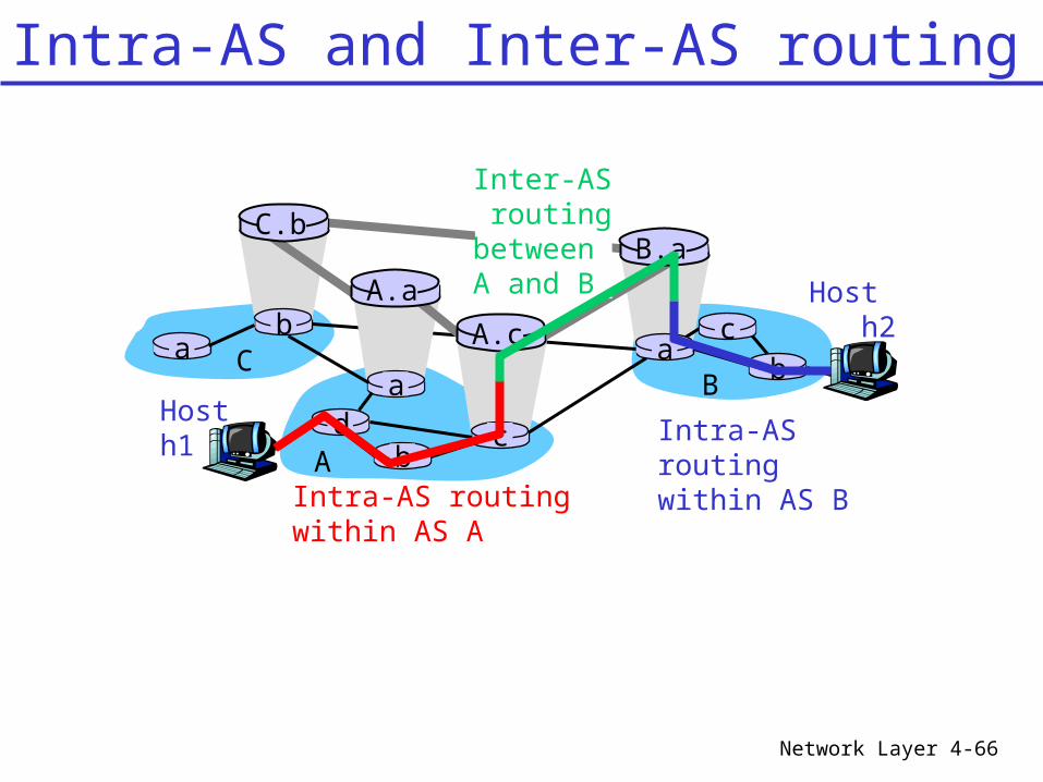
Intra-AS routingwithin AS A
Inter-AS routingbetween A and B
Intra-AS routingwithin AS B
Intra-AS and Inter-AS routing
Network Layer 4-67
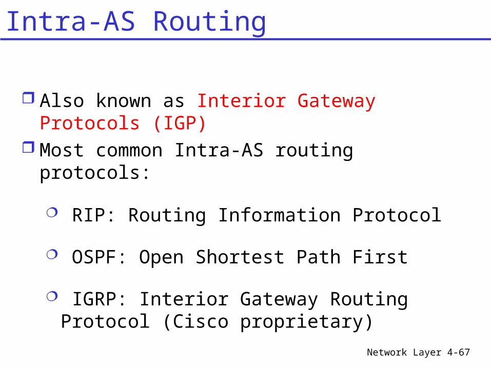
Also known as Interior Gateway Protocols (IGP)
Most common Intra-AS routing protocols:
RIP: Routing Information Protocol
OSPF: Open Shortest Path First
IGRP: Interior Gateway Routing Protocol (Cisco proprietary)
Intra-AS Routing
Network Layer 4-68
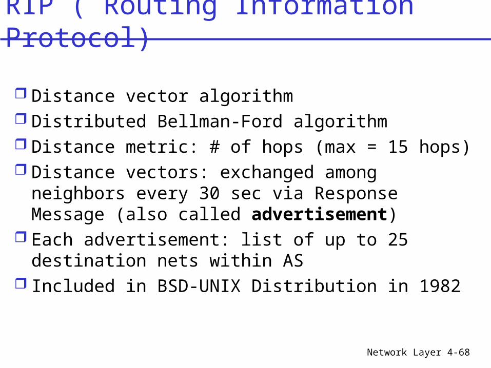
Distance vector algorithm Distributed Bellman-Ford algorithm Distance metric: # of hops (max = 15 hops) Distance vectors: exchanged among
neighbors every 30 sec via Response Message (also called advertisement)
Each advertisement: list of up to 25 destination nets within AS
Included in BSD-UNIX Distribution in 1982
RIP ( Routing Information Protocol)
Network Layer
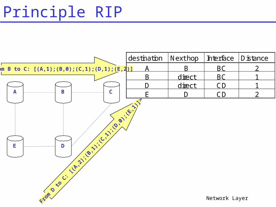
A B C
E D
From B to C: [(A,1);(B,0);(C,1);(D,1);(E,2)]
From
D to
C: [(
A,2);(B
,1);(C
,1);(D
,0);(E
,1)]
destination Next hop Interface Distance
A B BC 2B direct BC 1D direct CD 1E D CD 2
Principle RIP
Network Layer
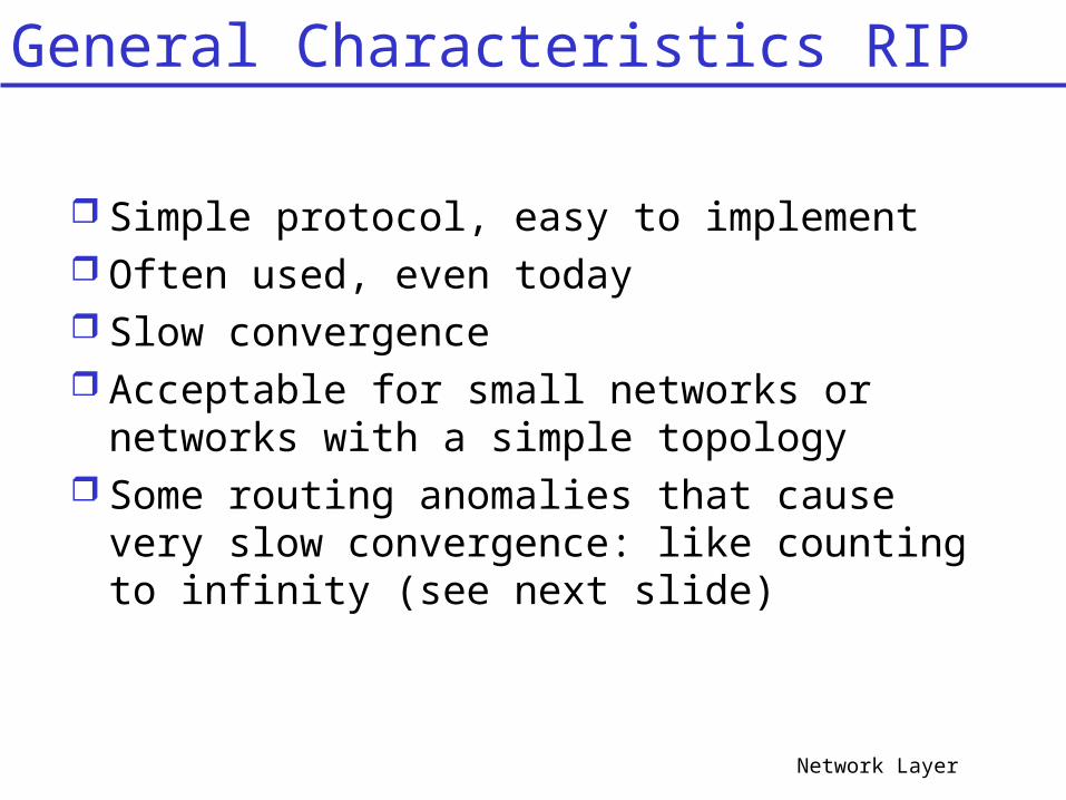
Simple protocol, easy to implement Often used, even today Slow convergence Acceptable for small networks or
networks with a simple topology Some routing anomalies that cause very
slow convergence: like counting to infinity (see next slide)
General Characteristics RIP
Network Layer
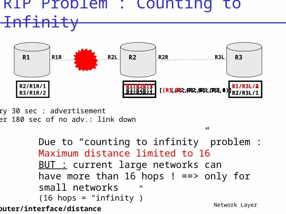
RIP Problem : Counting to Infinity
R1 R2 R3
R2/R1R/1R3/R1R/2
R1/R2L/1R3/R2R/1
R1R R2R R3LR2L
R1/R3L/2R2/R3L/1
R3/R2R/1R1/R2R/3R3/R2R/1R1/R2R/5R3/R2R/1
R1/R3L/4R2/R3L/1[(R2,0);(R3,1)][(R1,2);(R2,1);(R3,0)]
router/interface/distance
[(R1,3);(R2,0);(R3,1)][(R1,4);(R2,1);(R3,0)]
Due to “counting to infinity” problem :Maximum distance limited to 16BUT : current large networks canhave more than 16 hops ! ==> only for small networks (16 hops = “infinity”)
Every 30 sec : advertisementAfter 180 sec of no adv.: link down
Network Layer 4-72
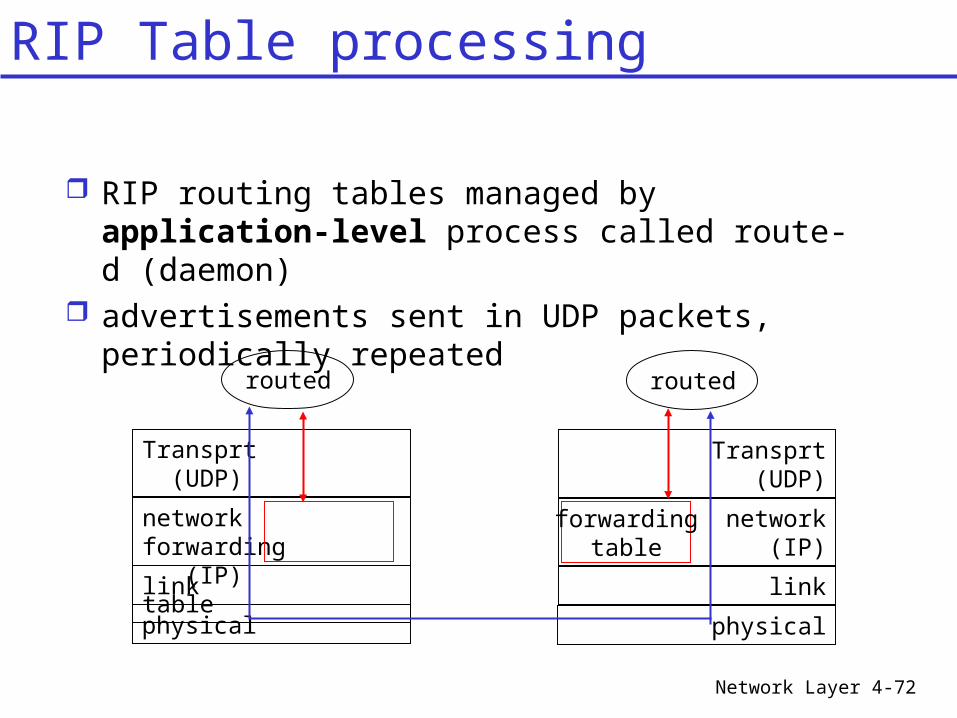
RIP routing tables managed by application-level process called route-d (daemon)
advertisements sent in UDP packets, periodically repeated
physical
link
network forwarding (IP) table
Transprt (UDP)
routed
physical
link
network (IP)
Transprt (UDP)
routed
forwardingtable
RIP Table processing
Network Layer
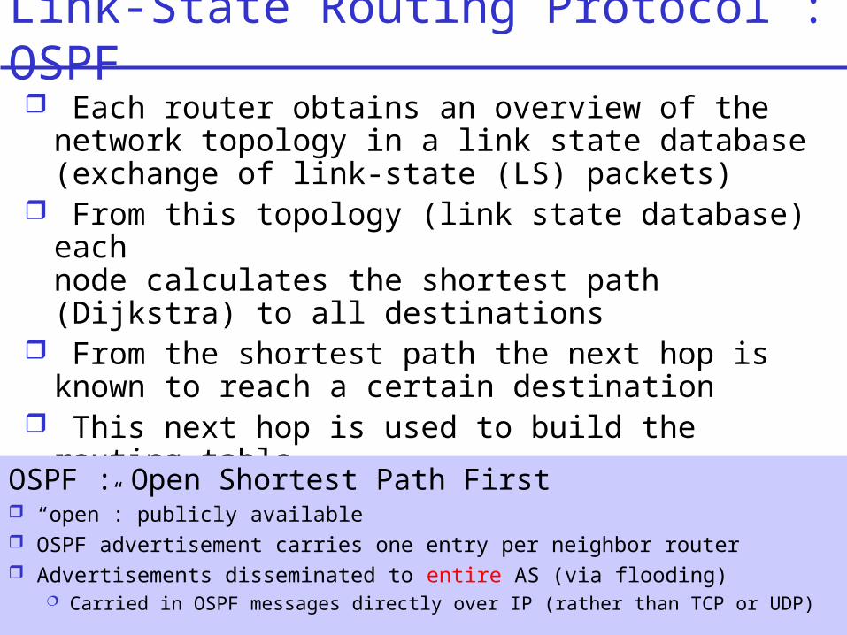
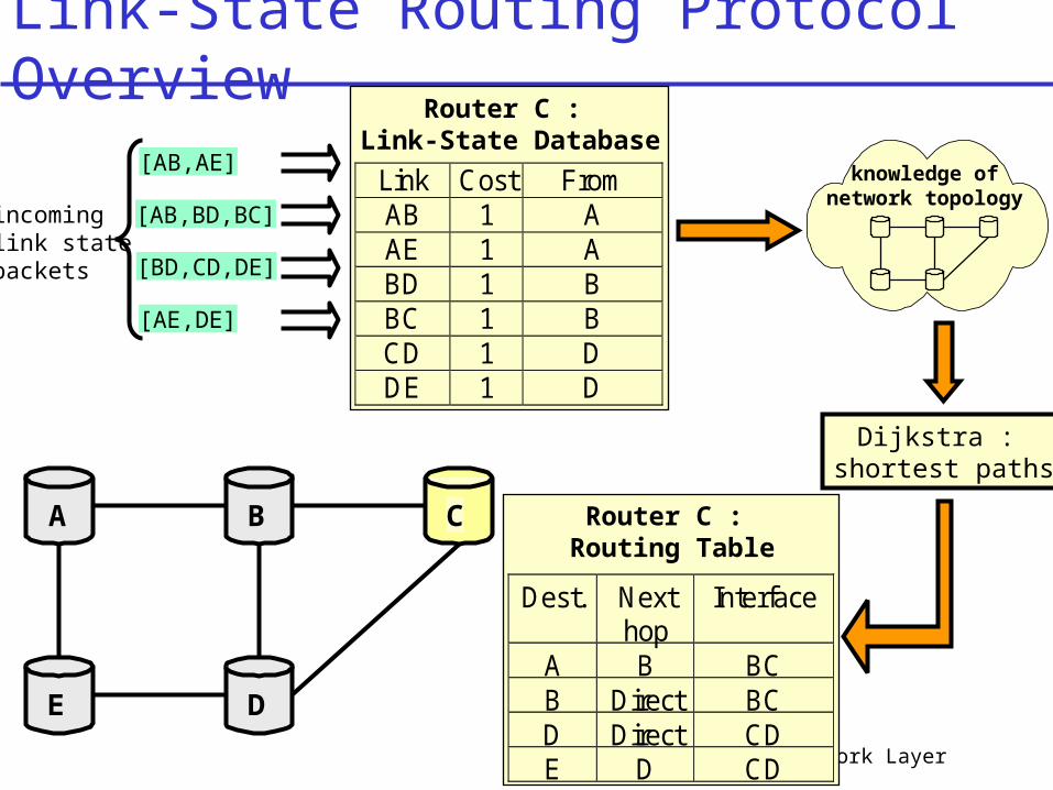
Link-State Routing Protocol : OSPF Each router obtains an overview of the
network topology in a link state database (exchange of link-state (LS) packets)
From this topology (link state database) each node calculates the shortest path (Dijkstra) to all destinations
From the shortest path the next hop is known to reach a certain destination
This next hop is used to build the routing table
OSPF : Open Shortest Path First “open”: publicly available OSPF advertisement carries one entry per neighbor router Advertisements disseminated to entire AS (via flooding)
Carried in OSPF messages directly over IP (rather than TCP or UDP)
Network Layer
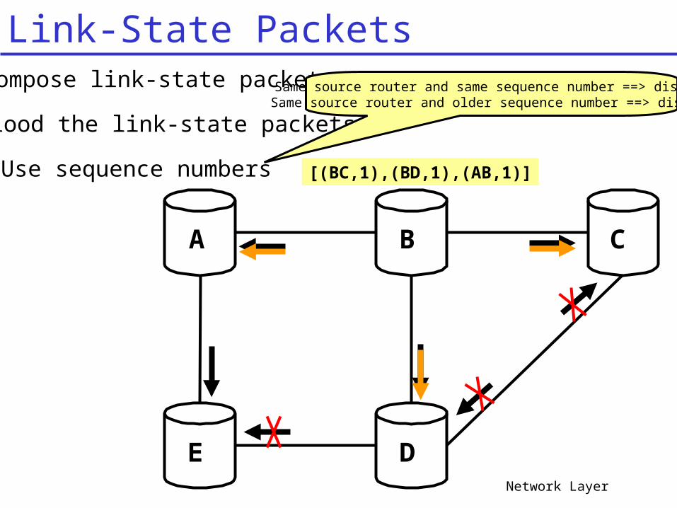
Compose link-state packets
Flood the link-state packets
A B C
E D
[(BC,1),(BD,1),(AB,1)]Use sequence numbers
Same source router and same sequence number ==> discardSame source router and older sequence number ==> discard
Link-State Packets
Network Layer
Link-State Routing Protocol Overview
A B C
E D
[AB,BD,BC]
[BD,CD,DE]
[AE,DE]
[AB,AE]
incominglink statepackets
Router C : Link-State Database
Link Cost From AB 1 A AE 1 A BD 1 B BC 1 B CD 1 D DE 1 D
knowledge ofnetwork topology
Dijkstra : shortest paths
Router C : Routing Table
Dest. Nexthop
Interface
A B BCB Direct BCD Direct CDE D CD
Network Layer 4-76
Security: all OSPF messages authenticated (to prevent malicious intrusion)
Multiple same-cost paths allowed (only one path in RIP)
For each link, multiple cost metrics for different TOS (e.g., satellite link cost set “low” for best effort; high for real time)
Integrated uni- and multicast support: Multicast OSPF (MOSPF) uses same topology
data base as OSPF Hierarchical OSPF in large domains.
OSPF “advanced” features (not in RIP)
Network Layer 4-77
BACKBONE
AREA 1AREA 2
AREA 3
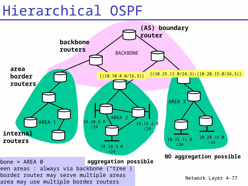
Hierarchical OSPF
10.10.3.0/24
10.10.2.0/24
10.10.6.0/24
10.20.15.0/24
10.25.11.0/24
[(10.10.0.0/16,3)] [(10.25.11.0/24,3);(10.20.15.0/24,3)]
internalrouters
areaborderrouters
backbonerouters
(AS) boundaryrouter
Backbone = AREA 0Between areas : always via backbone (“tree”)One border router may serve multiple areasOne area may use multiple border routers
aggregation possibleNO aggregation possible
Network Layer 4-78
Two-level hierarchy: local area, backbone. Link-state advertisements only in area each nodes has detailed area topology; only know
direction (shortest path) to nets in other areas. Internal Routers Area border routers: “summarize” distances to
nets in own area, advertise to other Area Border routers.
Backbone routers: run OSPF routing limited to backbone.
Boundary routers: connect to other AS’s.
Hierarchical OSPF
Network Layer 4-79
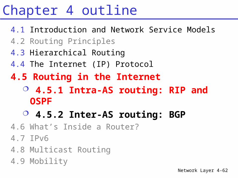
Chapter 4 outline4.1 Introduction and Network Service Models4.2 Routing Principles4.3 Hierarchical Routing4.4 The Internet (IP) Protocol
4.5 Routing in the Internet 4.5.1 Intra-AS routing: RIP and
OSPF 4.5.2 Inter-AS routing: BGP
4.6 What’s Inside a Router?4.7 IPv64.8 Multicast Routing4.9 Mobility
Network Layer 4-80
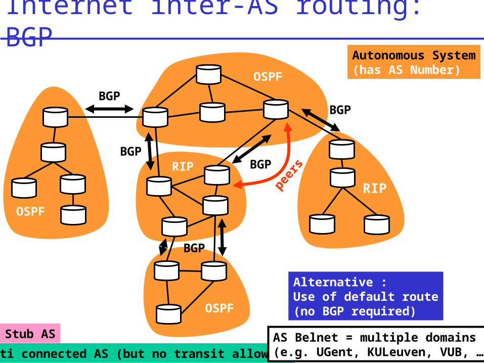
Internet inter-AS routing: BGPAutonomous System(has AS Number)
Stub AS
Multi connected AS (but no transit allowed)
BGP
OSPF
OSPF
RIP
RIP
OSPF
BGP
BGP
BGPBGP
Alternative : Use of default route(no BGP required)
AS Belnet = multiple domains(e.g. UGent, KULeuven, VUB, …)
peer
s
Network Layer 4-81
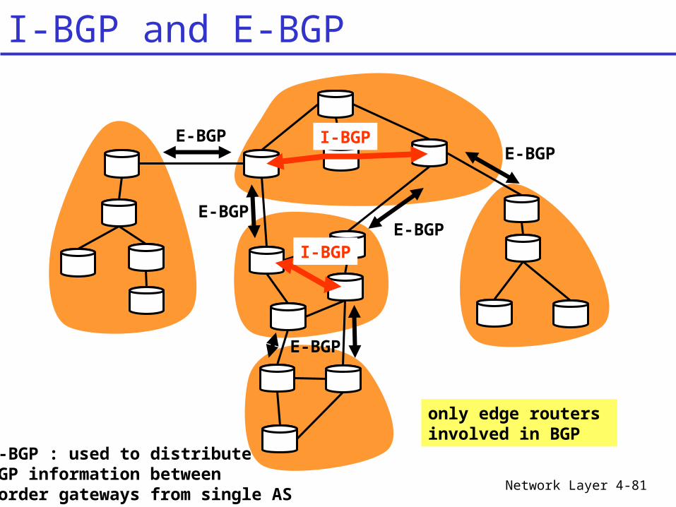
I-BGP and E-BGP
E-BGPE-BGP
E-BGP
E-BGPE-BGP
I-BGP
I-BGP
I-BGP : used to distributeBGP information between Border gateways from single AS
only edge routers involved in BGP
Network Layer 4-82
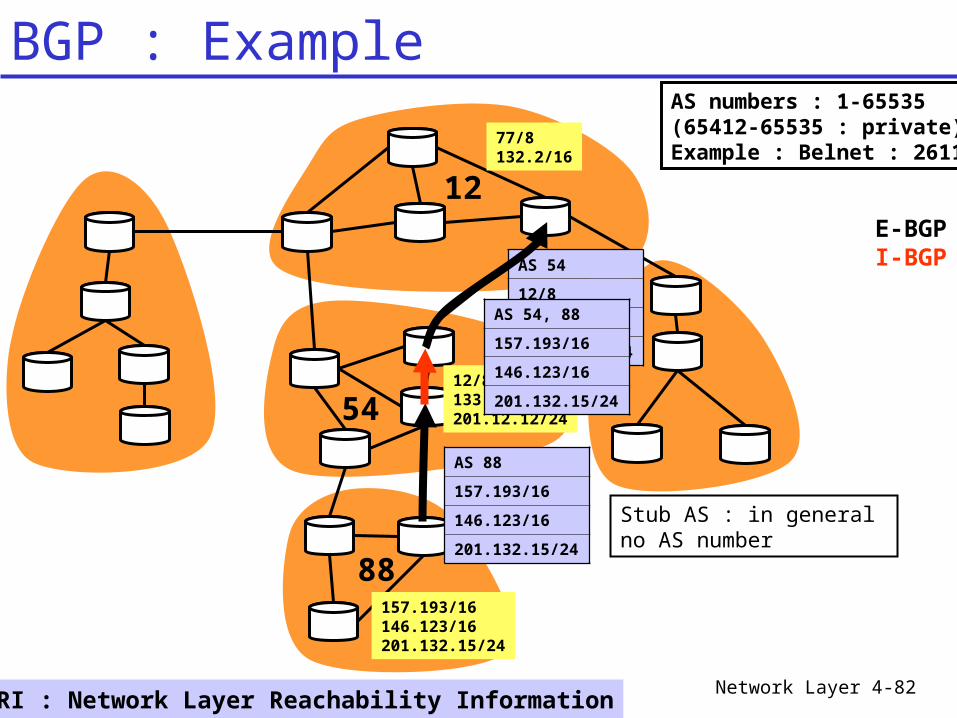
BGP : Example
12
54
88
Stub AS : in general no AS number
157.193/16146.123/16201.132.15/24
12/8133.12/16201.12.12/24
77/8132.2/16
AS 54
12/8
133.12/16
201.12.12/24
AS 88
157.193/16
146.123/16
201.132.15/24
NLRI : Network Layer Reachability Information
AS 54, 88
157.193/16
146.123/16
201.132.15/24
E-BGPI-BGP
AS numbers : 1-65535(65412-65535 : private)Example : Belnet : 2611
Network Layer 4-83
BGP4 (Border Gateway Protocol): the de facto standard
Path Vector protocol: similar to Distance Vector protocol each Border Gateway broadcasts to neighbors
(peers) entire path (i.e., sequence of AS’s) to destination (more general : NLRI information)
BGP announces routes to networks (CIDR enabled!), not individual hosts
Internet inter-AS routing: BGP
Network Layer 4-84
What does a BGP router do? Receiving and filtering route advertisements
from directly attached neighbor(s). Sending route advertisements to neighbors Route selection.
To route to destination X, which path (of several advertised) will be taken?
Filling routing table complex : based on AS_path, weight attribute, local preference attribute, …
BGP operation
Network Layer 4-85
Suppose: gateway X send its path to peer gateway W
W may or may not select path offered by X cost, policy (don’t route via competitors AS),
loop prevention reasons.
If W selects path advertised by X, then:Path (W,Z) = W, Path (X,Z)
Note: X can control incoming traffic by controlling its route advertisements to peers: e.g., don’t want to route traffic to Z -> don’t
advertise any routes to Z
BGP operation
Network Layer 4-86
BGP messages exchanged using TCP. BGP messages:
OPEN: opens TCP connection to peer and authenticates sender
UPDATE: advertises new path (or withdraws old)
KEEPALIVE keeps connection alive in absence of UPDATES; also ACKs OPEN request
NOTIFICATION: reports errors in previous msg; also used to close connection
BGP messages
Network Layer 4-87
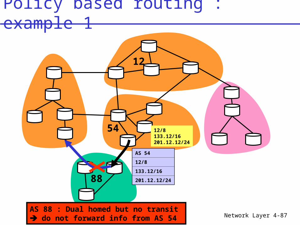
Policy based routing : example 1
12/8133.12/16201.12.12/24
12
54
88
AS 54
12/8
133.12/16
201.12.12/24
AS 88 : Dual homed but no transit do not forward info from AS 54
Network Layer 4-88
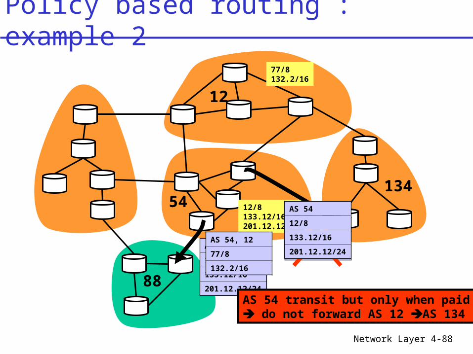
Policy based routing : example 2
12/8133.12/16201.12.12/24
12
54
88
AS 54
12/8
133.12/16
201.12.12/24 AS 54 transit but only when paid
do not forward AS 12 AS 134
AS 54, 12
77/8
132.2/16
77/8132.2/16
AS 54, 12
77/8
132.2/16
AS 54
12/8
133.12/16
201.12.12/24
134
Network Layer 4-89
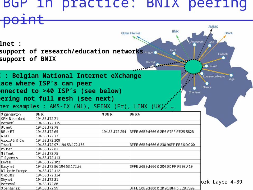
BGP in practice: BNIX peering point
Belnet : - support of research/education networks- support of BNIX
BNIX : Belgian National Internet eXchange- place where ISP’s can peer- connected to >40 ISP’s (see below)- peering not full mesh (see next)- other examples : AMS-IX (Nl), SFINX (Fr), LINX (UK), …
Organization BNIX MBNIX BNIX6KPN Nederland 194.53.172.71Versatel 194.53.172.115UUnet 194.53.172.78BELNET 194.53.172.65 194.53.172.254 3FFE:80B0:1000:0:2E0:F7FF:FE25:582B AT&T 194.53.172.77Arcor AG & Co 194.53.172.109Tiscali 194.53.172.97, 194.53.172.105 3FFE:80B0:1000:0:230:96FF:FEE6:DC00PSInet 194.53.172.82NETnet 194.53.172.75T-Systems 194.53.172.113Level3 194.53.172.102Easynet 194.53.172.96,194.53.172.98 3FFE:80B0:1000:0:204:DDFF:FE08:F10BT Ignite Europe 194.53.172.112X-router 194.53.172.124Skynet 194.53.172.81Perceval 194.53.172.80Opentransit 194.53.172.99 3FFE:80B0:1000:0:2D0:BBFF:FE28:7800
Network Layer 4-90
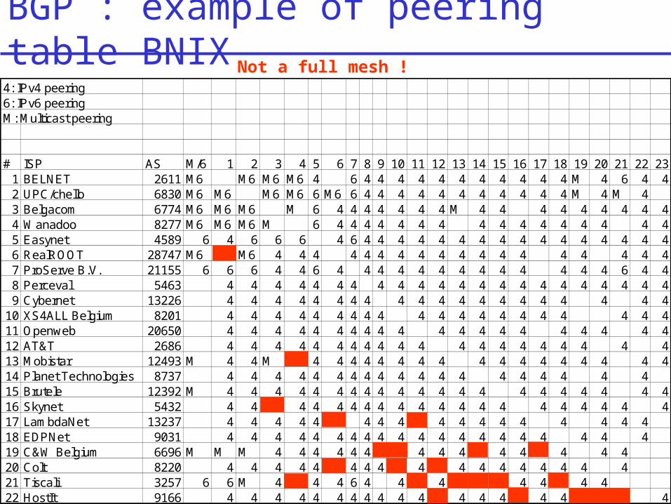
BGP : example of peering table BNIX
4: IPv4 peering 6: IPv6 peering M: Multicast peering
# ISP AS M/6 1 2 3 4 5 6 7 8 9 10 11 12 13 14 15 16 17 18 19 20 21 22 231 BELNET 2611 M6 M6 M6 M6 4 6 4 4 4 4 4 4 4 4 4 4 4 M 4 6 4 42 UPC/chello 6830 M6 M6 M6 M6 6 M6 6 4 4 4 4 4 4 4 4 4 4 4 M 4 M 43 Belgacom 6774 M6 M6 M6 M 6 4 4 4 4 4 4 4 M 4 4 4 4 4 4 4 4 44 Wanadoo 8277 M6 M6 M6 M 6 4 4 4 4 4 4 4 4 4 4 4 4 4 4 4 45 Easynet 4589 6 4 6 6 6 4 6 4 4 4 4 4 4 4 4 4 4 4 4 4 4 4 46 RealROOT 28747 M6 M6 4 4 4 4 4 4 4 4 4 4 4 4 4 4 4 4 4 47 ProServe B.V. 21155 6 6 6 4 4 6 4 4 4 4 4 4 4 4 4 4 4 4 4 6 4 48 Perceval 5463 4 4 4 4 4 4 4 4 4 4 4 4 4 4 4 4 4 4 4 4 4 49 Cybernet 13226 4 4 4 4 4 4 4 4 4 4 4 4 4 4 4 4 4 4 4 4
10 XS4ALL Belgium 8201 4 4 4 4 4 4 4 4 4 4 4 4 4 4 4 4 4 4 4 411 Openweb 20650 4 4 4 4 4 4 4 4 4 4 4 4 4 4 4 4 4 4 4 412 AT&T 2686 4 4 4 4 4 4 4 4 4 4 4 4 4 4 4 4 4 4 4 413 Mobistar 12493 M 4 4 M 4 4 4 4 4 4 4 4 4 4 4 4 4 4 4 4 414 Planet Technologies 8737 4 4 4 4 4 4 4 4 4 4 4 4 4 4 4 4 4 4 415 Brutele 12392 M 4 4 4 4 4 4 4 4 4 4 4 4 4 4 4 4 4 4 4 4 416 Skynet 5432 4 4 4 4 4 4 4 4 4 4 4 4 4 4 4 4 4 4 4 417 LambdaNet 13237 4 4 4 4 4 4 4 4 4 4 4 4 4 4 4 4 418 EDPNet 9031 4 4 4 4 4 4 4 4 4 4 4 4 4 4 4 4 4 4 4 419 C&W Belgium 6696 M M M 4 4 4 4 4 4 4 4 4 4 4 4 4 420 Colt 8220 4 4 4 4 4 4 4 4 4 4 4 4 4 4 4 4 421 Tiscali 3257 6 6 M 4 4 4 6 4 4 4 4 4 4 422 HostIt 9166 4 4 4 4 4 4 4 4 4 4 4 4 4 4 4 4 4
Not a full mesh !
Network Layer 4-91
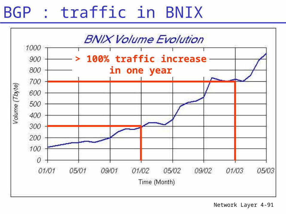
BGP : traffic in BNIX
> 100% traffic increasein one year
Network Layer 4-92
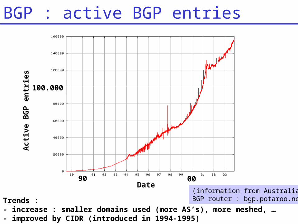
BGP : active BGP entriesA
cti
ve B
GP
en
trie
s
Date 90 00
100.000
Trends : - increase : smaller domains used (more AS’s), more meshed, …- improved by CIDR (introduced in 1994-1995)
(information from AustralianBGP router : bgp.potaroo.net)
Network Layer 4-93
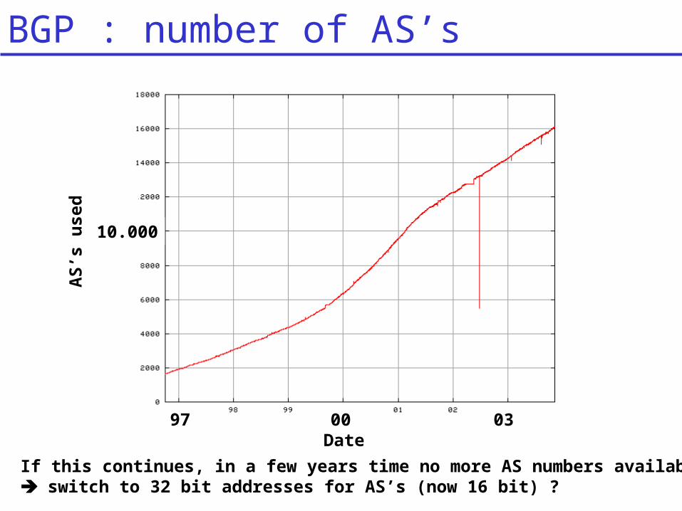
BGP : number of AS’sA
S’s
used
Date 97 03
10.000
If this continues, in a few years time no more AS numbers available switch to 32 bit addresses for AS’s (now 16 bit) ?
00
Network Layer 4-94
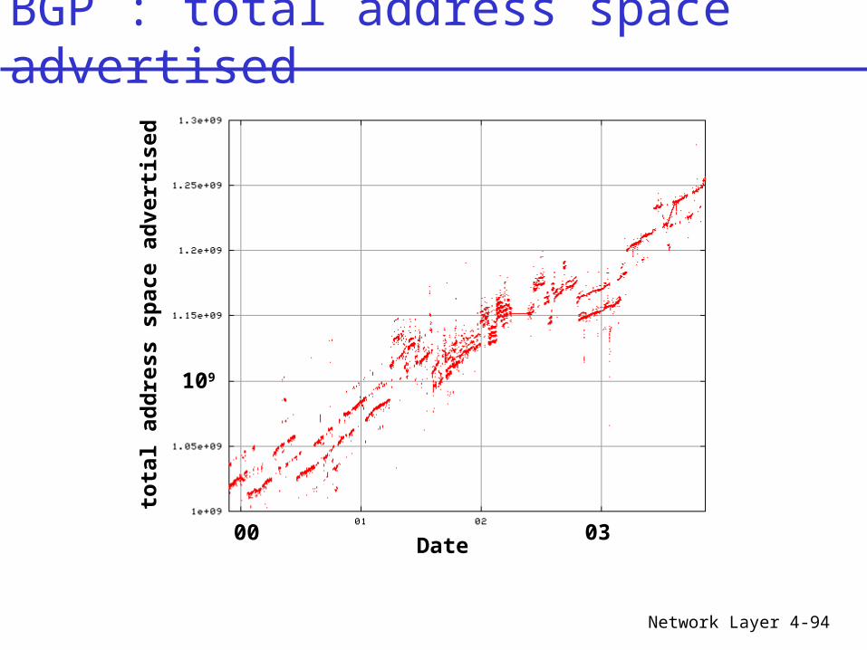
BGP : total address space advertised
tota
l ad
dre
ss s
pace a
dvert
ised
Date 00 03
109
Network Layer 4-95
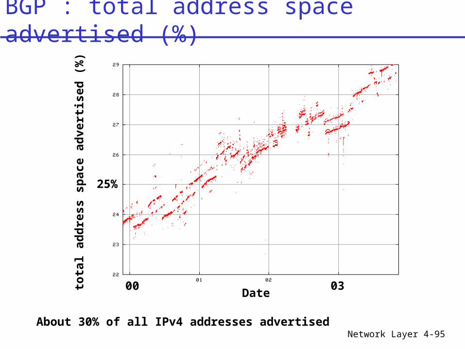
BGP : total address space advertised (%)
tota
l ad
dre
ss s
pace a
dvert
ised
(%
)
Date 00 03
25%
About 30% of all IPv4 addresses advertised
Network Layer 4-96
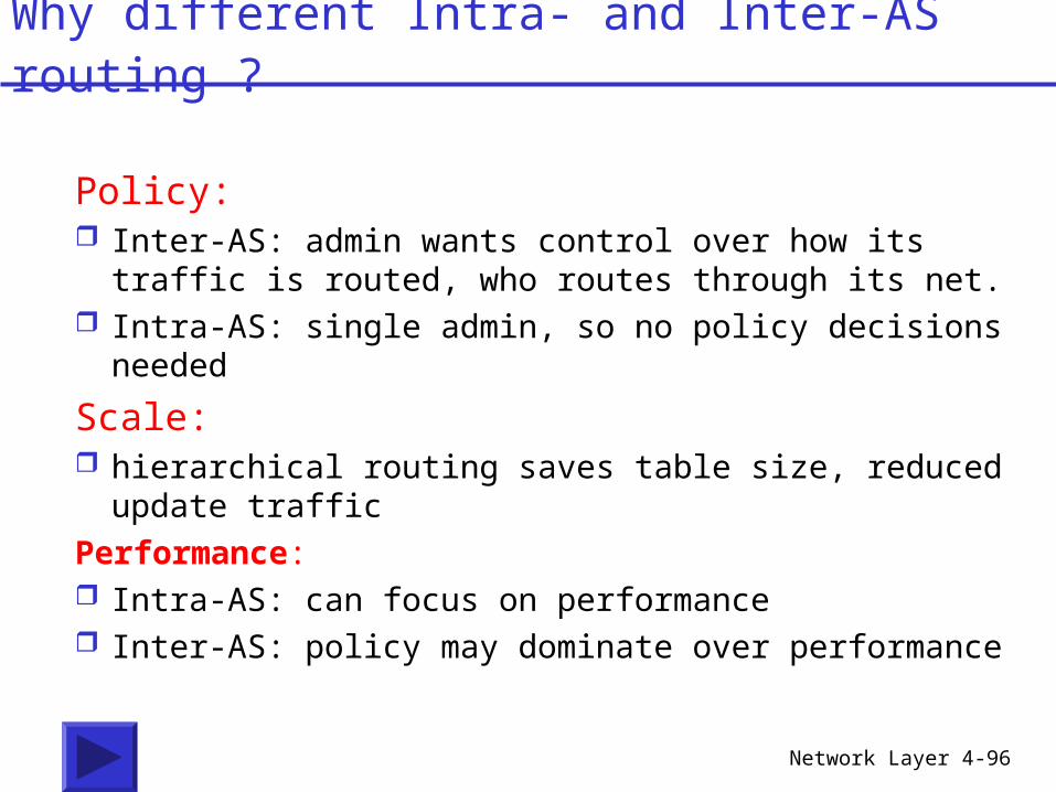
Policy: Inter-AS: admin wants control over how its traffic is
routed, who routes through its net. Intra-AS: single admin, so no policy decisions
needed
Scale: hierarchical routing saves table size, reduced
update trafficPerformance: Intra-AS: can focus on performance Inter-AS: policy may dominate over performance
Why different Intra- and Inter-AS routing ?
Network Layer 4-97
Chapter 4 outline
4.1 Introduction and Network Service Models
4.2 Routing Principles4.3 Hierarchical Routing4.4 The Internet (IP) Protocol4.5 Routing in the Internet4.6 What’s Inside a Router4.7 IPv64.8 Multicast Routing4.9 Mobility
Network Layer 4-98
Table of contents 4.1 Introduction and Network Service Models 2 4.4 The Internet (IP) Protocol 7
4.4.1 IPv4 addressing 8 4.4.2 Moving a datagram from source to destination 26 4.4.3 Datagram format 40 4.4.4 IP fragmentation 42 4.4.5 ICMP: Internet Control Message Protocol 45 4.4.6 DHCP: Dynamic Host Configuration Protocol 51 4.4.7 NAT: Network Address Translation 51
4.5 Routing in the Internet 62 4.5.1 Intra-AS routing: RIP and OSPF 62 4.5.2 Inter-AS routing: BGP 79
Outline 97 Table of contents 98