Embed Size (px)
Citation preview
MEF 59 © MEF Forum 2018. Any reproduction of this document, or any portion thereof, shall contain the following
statement: "Reproduced with permission of MEF Forum." No user of this document is authorized to modify any of the information contained herein.
MEF SPECIFICATION
MEF 59
Network Resource Management
Information Model:
Connectivity
January, 2018

MEF 59 © MEF Forum 2018. Any reproduction of this document, or any portion thereof, shall contain the following
statement: "Reproduced with permission of MEF Forum." No user of this document is authorized to modify any of the information contained herein.
Disclaimer
The information in this publication is freely available for reproduction and use by any recipient
and is believed to be accurate as of its publication date. Such information is subject to change
without notice and MEF Forum (MEF) is not responsible for any errors. MEF does not assume
responsibility to update or correct any information in this publication. No representation or war-
ranty, expressed or implied, is made by MEF concerning the completeness, accuracy, or applica-
bility of any information contained herein and no liability of any kind shall be assumed by MEF
as a result of reliance upon such information.
The information contained herein is intended to be used without modification by the recipient or
user of this document. MEF is not responsible or liable for any modifications to this document
made by any other party.
The receipt or any use of this document or its contents does not in any way create, by implication
or otherwise:
• any express or implied license or right to or under any patent, copyright, trademark or
trade secret rights held or claimed by any MEF member company which are or may be
associated with the ideas, techniques, concepts or expressions contained herein; nor
• any warranty or representation that any MEF member companies will announce any
product(s) and/or service(s) related thereto, or if such announcements are made, that such
announced product(s) and/or service(s) embody any or all of the ideas, technologies, or
concepts contained herein; nor
• any form of relationship between any MEF member companies and the recipient or user
of this document.
Implementation or use of specific MEF standards or recommendations and MEF specifications
will be voluntary, and no member shall be obliged to implement them by virtue of participation
in MEF Forum. MEF is a non-profit international organization to enable the development and
worldwide adoption of agile, assured and orchestrated network services. MEF does not, ex-
pressly or other-wise, endorse or promote any specific products or services.
© MEF Forum 2018. All Rights Reserved.

Network Resource Management - Information Model: Connectivity
MEF 59 © MEF Forum 2018. Any reproduction of this document, or any portion thereof, shall contain the following
statement: "Reproduced with permission of MEF Forum." No user of this document is authorized to modify any of the information contained herein.
Page i
Table of Contents
1 List of Contributing Members ........................................................................................... 1
2 Abstract ................................................................................................................................ 2
3 Terminology and Acronyms............................................................................................... 3
4 Scope..................................................................................................................................... 5
5 Introduction ......................................................................................................................... 9
6 Specification Approach Overview ................................................................................... 10
6.1 Motivation ....................................................................................................................... 10
6.2 Definition ......................................................................................................................... 12
7 Usage of Papyrus Modeling Environment ...................................................................... 13
8 Network Resource Information Model Overview .......................................................... 16
9 Network Resource Information Model Classes .............................................................. 18
9.1 Carrier Ethernet External and Internal Interfaces ............................................................ 18
9.2 Carrier Ethernet Connectivity End Point Resource ......................................................... 24
9.3 Carrier Ethernet Connectivity Resource .......................................................................... 28
10 Network Resource Information Model Type Definitions .............................................. 31
10.1 Data Types ....................................................................................................................... 31
10.2 Enumerations ................................................................................................................... 32
11 Imported Classes ............................................................................................................... 33
12 Imported Type Definitions ............................................................................................... 35
13 References .......................................................................................................................... 37
Appendix A Examples of Network Scenarios (Informative) ................................................ 39
Appendix B Examples of Extension Mechanisms (Informative) ......................................... 47
Appendix C Mappings from MEF 7.3 to NRM (Informative) ............................................. 49
Appendix D Summary Table of Classes (Informative) ......................................................... 56

Network Resource Management - Information Model: Connectivity
MEF 59 © MEF Forum 2018. Any reproduction of this document, or any portion thereof, shall contain the following
statement: "Reproduced with permission of MEF Forum." No user of this document is authorized to modify any of the information contained herein.
Page ii
List of Figures
Figure 1 - MEF NRM extending ONF TAPI .................................................................................. 6
Figure 2 - MEF NRM positioning in LSO RA ............................................................................... 7
Figure 3 - Example of ONF specification extension .................................................................... 12
Figure 4 - Graphical Notations for Object Classes ....................................................................... 13
Figure 5 - Overall relationship between MEF NRM IM and ONF TAPI ..................................... 16
Figure 6 - Service Interface Points Diagram................................................................................. 18
Figure 7 - Connectivity Service End Point Diagram .................................................................... 24
Figure 8 - Connectivity Service Diagram ..................................................................................... 28
Figure 9 - Single Provider, separately managed domains............................................................. 39
Figure 10 - Single Provider, single managed domain, partitioning .............................................. 40
Figure 11 - Different Operators .................................................................................................... 41
Figure 12 - Different Operators, separately managed domains .................................................... 42
Figure 13 - Different Operators, Partitioning ............................................................................... 43
Figure 14 - SP and two Operators: provisioning flow .................................................................. 44
Figure 15 - SP and one Operator: provisioning flow .................................................................... 45
Figure 16 - Scenario with Multiple Operators (MEF 26.2 [7])..................................................... 46
Figure 17 - EVC/OVC/Connectivity Service ............................................................................... 46
Figure 18 - Example of UML generalization ................................................................................ 47
Figure 19 - Example of UML composition................................................................................... 47
Figure 20 - Example of untyped extension ................................................................................... 48
Figure 21 - Example of ONF specification extension .................................................................. 48
Figure 22 - UNI and ENNI at Physical Layer............................................................................... 49
Figure 23 - UNI (Frame Aggregation Layer) ............................................................................... 50

Network Resource Management - Information Model: Connectivity
MEF 59 © MEF Forum 2018. Any reproduction of this document, or any portion thereof, shall contain the following
statement: "Reproduced with permission of MEF Forum." No user of this document is authorized to modify any of the information contained herein.
Page iii
Figure 24 - ENNI (Frame Aggregation Layer) ............................................................................. 52
Figure 25 - EVC/OVC End Point ................................................................................................. 53
Figure 26 - EVC, OVC ................................................................................................................. 54
List of Tables
Table 1 - Terminology and Acronyms ............................................................................................ 4
Table 2 - Attributes of CarrierEthPhysicalLinksResource Class .................................................. 19
Table 3 - Attributes of CarrierEthInterfaceResource Class .......................................................... 20
Table 4 - Attributes of CarrierEthUniNResource Class ............................................................... 21
Table 5 - Attributes of CarrierEthEnniNResource Class .............................................................. 22
Table 6 - Attributes of CarrierEthConnectivityEndPointResource Class ..................................... 27
Table 7 - Attributes of CarrierEthConnectivityResource Class .................................................... 30
Table 8 - FrameDeliveryCondition Data Type ............................................................................. 31
Table 9 - vlanIdListAndUntag Data Type .................................................................................... 31
Table 10 - Summary Table of Managed Object Classes............................................................... 56

Network Resource Management - Information Model: Connectivity
MEF 59 © MEF Forum 2018. Any reproduction of this document, or any portion thereof, shall contain the following statement: "Reproduced with permission of MEF Forum." No user of this document is authorized to modify
any of the information contained herein.
Page 1
1 List of Contributing Members
The following members of the MEF participated in the development of this document and have
requested to be included in this list.
CenturyLink
Ciena Corporation
Cisco Systems
Coriant
Ericsson
Huawei Technologies
Infinera Corporation
NEC Corporation
Nokia
RAD Data Communications

Network Resource Management - Information Model: Connectivity
MEF 59 © MEF Forum 2018. Any reproduction of this document, or any portion thereof, shall contain the following statement: "Reproduced with permission of MEF Forum." No user of this document is authorized to modify
any of the information contained herein.
Page 2
2 Abstract
This specification describes the MEF Network Resource Management Information Model (NRM
IM).
Lifecycle Service Orchestration Reference Architecture (LSO RA, MEF 55 [10]) extends the tra-
ditional MEF scope concerning Service Modeling, from a pure view “from outside the network”
to cover a range of Operational, Orchestration, and Network Management behaviors, including
SDN and NFV paradigms.
In support to MEF 55 [10], NRM IM is then defined to manage the Network Infrastructure, through
SDN Controllers, WAN Controllers, OTN Subnetwork Managers, and other legacy Network Man-
agement Systems.
The NRM IM structure is based on current and developing best network management solutions by
ITU-T, ONF, TM Forum, to allow wider and future proof interoperability across multi-vendor and
multi-technology networks. Examples of reference network management solutions are ITU-T
G.7711/Y.1702 [12], ONF TR-512 [15], ONF TR-527 [16], TM Forum MTNM [20] and MTOSI
[21].
The NRM IM models the management features defined by MEF Service Information Model (MEF
7.3 [4]) in a resource-oriented view, at network level, i.e. potentially spanning more technology
domains supporting the service. This model can be used as the basis for LSO RA PRESTO Inter-
face Profiles defining APIs.
This document normatively includes the content of the following Papyrus [18] UML files as if
they were contained within this document (pull request #587, GitHub Repository [11]):
• NRM_Connectivity.di
• NRM_Connectivity.notation
• NRM_Connectivity.uml

Network Resource Management - Information Model: Connectivity
MEF 59 © MEF Forum 2018. Any reproduction of this document, or any portion thereof, shall contain the following statement: "Reproduced with permission of MEF Forum." No user of this document is authorized to modify
any of the information contained herein.
Page 3
3 Terminology and Acronyms
This section defines the terms used in this document. In those cases where the normative defini-
tions of terms are found in other documents the third column is used to provide the reference that
is controlling.
Terms defined in MEF specifications MEF 6.2 [2], MEF 7.3 [4], MEF 10.3 [5], MEF 12.2 [6],
MEF 26.2 [7], MEF 45 [8], MEF 55 [10], TMF GB922 [19] are included in this document by
reference and, hence, not repeated in the table below, unless when mentioned in local definitions,
e.g. ICM.
Term Definition Reference
ICM Infrastructure Control and Management: The set
of functionality providing domain specific net-
work and topology view resource management
capabilities including configuration, control and
supervision of the network infrastructure.
MEF 55 [10]
Internal Network-
to-Network
Interface (INNI)
A reference point representing the boundary be-
tween two networks or network elements that are
operated within the same administrative domain.
Note: In this specification, the “networks or net-
work elements” refers to those in a given ICM
Domain, hence, between two ICM domains.
MEF 4 [1]
MEF 55 [10]
NRM IM Network Resource Management Information
Model
This document
Product Instance Specific implementation of a Product Offering
dedicated to the benefit of a party.
TMF GB922 [19]
Product Offering An externally facing representation of a Service
and/or Resource procurable by the Customer.
TMF GB922 [19]

Network Resource Management - Information Model: Connectivity
MEF 59 © MEF Forum 2018. Any reproduction of this document, or any portion thereof, shall contain the following statement: "Reproduced with permission of MEF Forum." No user of this document is authorized to modify
any of the information contained herein.
Page 4
Term Definition Reference
Product
Specification
The detailed description of product characteristics
and behavior used in the definition of Product Of-
ferings.
TMF GB922 [19]
Resource A physical or non-physical component (or some
combination of these) within a Service Provider’s
infrastructure or inventory.
TMF GB922 [19]
Service Represents the Customer experience of a Product
Instance that has been realized within the Service
Provider’s and / or Partners’ infrastructure.
TMF GB922 [19]
Service Component A segment or element of a Service that is man-
aged independently by the Service Provider.
MEF 55 [10]
TAPI or T-API Transport API Information Model ONF TR-527 [16]
ONF TAPI IM [17]
UML Unified Modeling Language OMG UML, Infra-
structure, Version
2.5
Table 1 - Terminology and Acronyms

Network Resource Management - Information Model: Connectivity
MEF 59 © MEF Forum 2018. Any reproduction of this document, or any portion thereof, shall contain the following statement: "Reproduced with permission of MEF Forum." No user of this document is authorized to modify
any of the information contained herein.
Page 5
4 Scope
The scope of this specification is a protocol neutral definition of the information, i.e., the attributes
(or properties), of the network resource management objects including
• Ethernet technology constructs,
• the adaptation of MEF 7.21 [3], Q.840.1 [14], G.8052 [13], MEF 12.2 [6] equivalent
constructs, plus any additional construct necessary to map equivalent MEF 7.3 [4] Service
constructs.
Functional references are MEF 6.2 [2], MEF 10.3 [5], MEF 26.2 [7], MEF 45 [8], MEF 51 [9].
The MEF NRM IM reuses and extends the definitions of the ONF Transport API Information
Model (TAPI IM [16], [17]), which is derived from the ONF Core Information Model ([15]).
The ONF Core IM is a common information model for network/transport technologies, evolution
of TMF and ITU-T models. It is extensible to new features/functions.
The TAPI model is derived from the ONF Core IM to make this more oriented to an
implementation of transport network management interface. It standardizes a single core
technology-agnostic model that abstracts common transport network functions.
The TAPI capabilities are extended through the specification approach. The essential concept is
to associate an instance of a TAPI class with a set of extensions that account for the specific case
(specification class). These specification classes are definitions of specific cases of usage of a class
to be extended.
The modeling of capability necessarily involves the modeling of constraints and rules, as a specific
capability is always restricted in some way with respect to the maximum possible capability. The
ONF Specification approach focusses on model of constrained capability.
Clearly a UML class model provides a definition of capability in terms of things that can be created
and values that can be set. However, the full ONF Core IM and TAPI go way beyond the capability
of any real solution. It is therefore necessary for any particular solution to be able to state its
specific capabilities. The term used by ONF for the modeling of capabilities is "Capability
Specification" or "Specification" or "Spec" for short.
See TR-512.7 Specification Model [15], “2.2 Rationale for, and features of, the ONF Specification
approach”.
1 Note that MEF 7.2 has been superseded by MEF 7.3. It is referenced because it includes “resource oriented” man-
agement features.

Network Resource Management - Information Model: Connectivity
MEF 59 © MEF Forum 2018. Any reproduction of this document, or any portion thereof, shall contain the following statement: "Reproduced with permission of MEF Forum." No user of this document is authorized to modify
any of the information contained herein.
Page 6
The MEF NRM IM is designed around a set of specification classes which extends, or augments,
TAPI classes. See Figure 1 below.
Figure 1 - MEF NRM extending ONF TAPI
While the NRM IM classes are designed to augment selected TAPI classes, the formal
augmentation is specified in interface specific models, which are described by Interface Profile
Specifications.

Network Resource Management - Information Model: Connectivity
MEF 59 © MEF Forum 2018. Any reproduction of this document, or any portion thereof, shall contain the following statement: "Reproduced with permission of MEF Forum." No user of this document is authorized to modify
any of the information contained herein.
Page 7
The MEF NRM IM classes are applicable to PRESTO Interface Reference Point (MEF 55 [10]),
see Figure 2 below.
Figure 2 - MEF NRM positioning in LSO RA
The definition of MEF NRM IM is necessary to ensure both:
• LSO RA internal consistency. All MEF models will use applicable model elements from
the NRM IM.
• LSO RA external consistency. This enables the LSO RA to interface with standard
network management models, such as those from the ITU-T and the ONF.
This will allow the LSO RA to be used with managed, multi-vendor, multi-technology
network infrastructures.
This specification includes Carrier Ethernet connectivity resource management features, identified
as the set of management features supported by MEF 7.3 ([4]) at service level.
MEF 7.3 features not included in this specification are:

Network Resource Management - Information Model: Connectivity
MEF 59 © MEF Forum 2018. Any reproduction of this document, or any portion thereof, shall contain the following statement: "Reproduced with permission of MEF Forum." No user of this document is authorized to modify
any of the information contained herein.
Page 8
• Virtual UNI model
• Performance Monitoring.
Some of the UML diagrams are very dense. To view them either zoom (sometimes to 400%) or
open the corresponding UML diagram via Papyrus [18] (for each figure with a UML diagram the
UML model diagram name is provided under the figure in italic font).

Network Resource Management - Information Model: Connectivity
MEF 59 © MEF Forum 2018. Any reproduction of this document, or any portion thereof, shall contain the following statement: "Reproduced with permission of MEF Forum." No user of this document is authorized to modify
any of the information contained herein.
Page 9
5 Introduction
The following sections of this document include:
• The description of the ONF Specification approach (6)
• The Papyrus [18] UML constructs used in this specification (7)
• The overview of NRM IM classes (8)
• The list of all defined object classes and their attributes for:
o Carrier Ethernet External and Internal Interfaces (9.1)
o Carrier Ethernet ConnectivityEnd Point (9.2)
o Carrier Ethernet Connectivity (9.3)
• The definitions of types and enumerations (10)
• The imported classes (11) and types (12)
• References (13)
• Appendix A lists the relevant network scenarios
• Appendix B presents some mechanisms to extend the definition of a class
• Appendix C presents an overview of the MEF 7.3 [4] to NRM IM mapping choices
• Appendix D provides a mapping table of the NRM IM classes to analogous classes defined
by other relevant SDOs

Network Resource Management - Information Model: Connectivity
MEF 59 © MEF Forum 2018. Any reproduction of this document, or any portion thereof, shall contain the following statement: "Reproduced with permission of MEF Forum." No user of this document is authorized to modify
any of the information contained herein.
Page 10
6 Specification Approach Overview
6.1 Motivation
Both Core IM [15] and TAPI [17] models are designed to be inherently invariant with respect to:
• networking technologies and their evolutions,
• vendor specific extensions (e.g. new features not yet standardized anywhere) and/or vari-
ations (e.g. specific optimized solutions).
To supply a usable management model, the technology specific models (e.g. Ethernet, OTN,
MPLS-TP) and the possible vendor extensions must be “plugged into” TAPI model.
UML provides inheritance and composition associations to augment a class definition, but both
mechanisms require that the entire schema is coded prior to compile. In other words, every time
e.g. ITU-T defines a new attribute of ODU CTP, then the whole model (generic and specific
parts) shall be necessarily modified and recompiled. This is costly, for the delivery time, the
backward compatibility management, the massive update of software in the network, etc.
So far, a common solution was to replace UML inheritance and composition by the “additional
info” or “name-value pairs” paradigm, i.e. untyped attributes where to model the specific stand-
ard items (e.g. IEEE Ethernet parameters) and the vendor specific extensions. This approach sup-
plied a reasonable compromise between the conflicting requirements of flexibility and interoper-
ability. For example, the new attribute of ODU CTP is simply documented in natural language as
a name-value pair. See Appendix B for some examples of extension mechanisms.
This compromise is no longer sustainable given the increasing flexibility and softwarization that
is required to modern networks. In fact, the limits of this approach are that:
• Relevant if not most part of the model is not machine interpretable (e.g. all the ODU or
Ethernet specific attributes, together with all vendor extensions). These specific modeling
items shall be (manually) added later in the software production stages.
• Manual work is necessary to create and maintain the natural language definitions of ex-
tensions, even if such extensions are originally defined in UML by reference SDOs. As
technology specific models are developed by different SDOs, in different times and with
different paces, the alignment effort is excessive.

Network Resource Management - Information Model: Connectivity
MEF 59 © MEF Forum 2018. Any reproduction of this document, or any portion thereof, shall contain the following statement: "Reproduced with permission of MEF Forum." No user of this document is authorized to modify
any of the information contained herein.
Page 11
The two items above cause additional costs specially in new product introduction, migration, etc.
It is then necessary to increase the degree of modeling softwarization: ONF proposed solution is
called “specification approach” 2.
The specification approach provides both the flexibility of “additional info” pattern and the ri-
gors of UML definitions.
The essential approach is to define “specification classes” which are associated to the classes
they refine. One key distinction with UML composition association is the class definition is
never aware of any augmenting specification class. So the core model and the specific model can
be decoupled till to run time stage, like using “additional info”, but with the “additional info” be-
ing described in UML. This is a basis for the realization of model federation.
Note that specification classes must be leaves of the inheritance hierarchy.
2 “specification approach” or “specification pattern”, but this last expression can be confused with other existing
specification patterns.

Network Resource Management - Information Model: Connectivity
MEF 59 © MEF Forum 2018. Any reproduction of this document, or any portion thereof, shall contain the following statement: "Reproduced with permission of MEF Forum." No user of this document is authorized to modify
any of the information contained herein.
Page 12
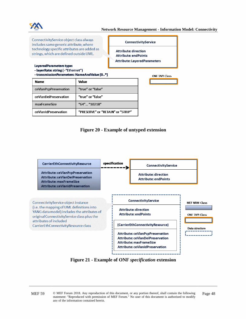
6.2 Definition
A specification class is a specialized construct, originally used in the ONF TAPI [17], to insert
the attributes of one class into a second class. For example, this enables vendor-specific parame-
ters to be added to standard data models in an interoperable way.
The following is a simple example, showing that the attributes of the CarrierEthConnectivi-
tyResource class are inserted into a ConnectivityService class.
Figure 3 - Example of ONF specification extension
Note: the symbology used is that of a UML dependency. Indeed, in this example, CarrierEthCon-
nectivityResource requires ConnectivityService to complete its definition. However, the motiva-
tion for using this construct is to more easily build YANG [22] data models. Hence, the resulting
data structure desired is a YANG view, which means that the attributes of CarrierEthConnectivi-
tyResource are actually contained in the ConnectivityService class. (In UML, you would have
CarrierEthConnectivityResource associated to a ConnectivityService).
Network Resource Management - Information Model: Connectivity
MEF 59 © MEF Forum 2018. Any reproduction of this document, or any portion thereof, shall contain the following statement: "Reproduced with permission of MEF Forum." No user of this document is authorized to modify
any of the information contained herein.
Page 13
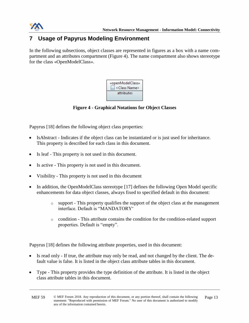
7 Usage of Papyrus Modeling Environment
In the following subsections, object classes are represented in figures as a box with a name com-
partment and an attributes compartment (Figure 4). The name compartment also shows stereotype
for the class «OpenModelClass».
Figure 4 - Graphical Notations for Object Classes
Papyrus [18] defines the following object class properties:
• IsAbstract - Indicates if the object class can be instantiated or is just used for inheritance.
This property is described for each class in this document.
• Is leaf - This property is not used in this document.
• Is active - This property is not used in this document.
• Visibility - This property is not used in this document
• In addition, the OpenModelClass stereotype [17] defines the following Open Model specific
enhancements for data object classes, always fixed to specified default in this document:
o support - This property qualifies the support of the object class at the management
interface. Default is “MANDATORY”
o condition - This attribute contains the condition for the condition-related support
properties. Default is “empty”.
Papyrus [18] defines the following attribute properties, used in this document:
• Is read only - If true, the attribute may only be read, and not changed by the client. The de-
fault value is false. It is listed in the object class attribute tables in this document.
• Type - This property provides the type definition of the attribute. It is listed in the object
class attribute tables in this document.

Network Resource Management - Information Model: Connectivity
MEF 59 © MEF Forum 2018. Any reproduction of this document, or any portion thereof, shall contain the following statement: "Reproduced with permission of MEF Forum." No user of this document is authorized to modify
any of the information contained herein.
Page 14
• Multiplicity - This property defines the number of values the attribute can simultaneously
have. * is a list attribute with 0, one or multiple values. It is listed in the object class attribute
tables in this document.
• Default value - This property provides the value that the attribute has to start with in case the
value is not provided during creation, or already defined because of a system state. In cases
where a default value makes no sense, it is undefined. It is listed in the object class attribute
tables in this document.
• Aggregation - This property specifies the type of the association when the attribute is from an
association. It is shown in the associations in the class diagram figures.
• Is derived - fixed to default value “is false”.
• Is derived union - fixed to default value “is false”.
• Is leaf - fixed to default value “is false”.
• Is ordered - For a multi-valued multiplicity; this specifies whether the values in an instantia-
tion of this attribute are sequentially ordered; fixed to default value “is false”.
• Is static - fixed to default value “is false”.
• In addition, the OpenModelAttribute stereotype [17] defines the following Open Model spe-
cific enhancements for attributes, always fixed to specified default in this document:
o partOfObjectKey - This property indicates if the attribute is part of the object key
or not. It is not listed in the object class tables in this document. Default is “0” (no
part of object key). In this specification, there are no object key attributes because
the defined classes augment the TAPI classes, which have their object key attrib-
utes. Similarly, for referenced MEF Common classes.
o uniqueSet - This property defines if the attribute is part of a set of attributes which
together (i.e., their values) have to be unique among all instances within a defined
context. No value means no uniqueness constraint. Default is “no value”.
o isInvariant - This property defines at which time the attribute can be set, true = at-
tribute can only be set at creation time; false = attribute can be set at any time. De-
fault is “false”.
o valueRange - This property provides the restriction on the attribute values. Default
is “empty”, i.e. no restrictions.
o unsigned - This optional property indicates if the attribute type is unsigned (value
= true) or signed (value = false); if applicable, otherwise ignored. Default is
“false”.

Network Resource Management - Information Model: Connectivity
MEF 59 © MEF Forum 2018. Any reproduction of this document, or any portion thereof, shall contain the following statement: "Reproduced with permission of MEF Forum." No user of this document is authorized to modify
any of the information contained herein.
Page 15
o counter - This optional property defines the counter type of the attribute type; if
applicable. Default is “NA” (Not Applicable).
o unit - This optional property contains a textual definition of the unit associated
with the attribute value. The spelling of the unit (not only SI units) shall be in ac-
cordance to the NIST Publication 811 “Guide for the Use of the International Sys-
tem of Units (SI)” (http://www.nist.gov/pml/pubs/sp811/index.cfm), section 9
“Rules and Style Conventions for Spelling Unit Names”. Default is “empty”.
o support - This property qualifies the support of the attribute at the management
interface. Default is “MANDATORY”.
o condition - This attribute contains the condition for the condition-related support
properties. Default is “empty”.
• In addition, the Reference stereotype [17] defines the following Open Model specific en-
hancement for attributes:
o reference - This attribute contains the reference upon which the UML artefact is
based. A reference to a standard is preferred.
In the following sections, the attribute tables list all the attributes defined for that class, including
the attributes generated from the associations (attribute names start with “_”). Note that some of
these association attributes are not shown in the diagrams, while correctly listed in the tables.
This is an anomaly of used version of Papyrus [18].
The inherited attributes are not listed, neither in tables nor in diagrams.

Network Resource Management - Information Model: Connectivity
MEF 59 © MEF Forum 2018. Any reproduction of this document, or any portion thereof, shall contain the following statement: "Reproduced with permission of MEF Forum." No user of this document is authorized to modify
any of the information contained herein.
Page 16
8 Network Resource Information Model Overview
Figure 5 shows how NRM IM classes augment the ONF TAPI classes:
Figure 5 - Overall relationship between MEF NRM IM and ONF TAPI
• The CarrierEthConnectivityResource represents the Ethernet end to end connectivity at
resource level. It may represent an original EVC, OVC, or Service Component. It augments
the TAPI ConnectivityService class, which represents the request for connectivity between
two or more TAPI ConnectivityServiceEndPoint. More detailed connection and routing in-
formation are modeled by different constructs of TAPI.
• The CarrierEthConnectivityEndPointResource class models the service end point. It aug-
ments the TAPI ConnectivityServiceEndPoint.
The relationship between CarrierEthConnectivityResource and its CarrierEthConnectivi-
tyEndPointResource is modeled through the relationship between ConnectivityService and
ConnectivityServiceEndPoint of TAPI model.

Network Resource Management - Information Model: Connectivity
MEF 59 © MEF Forum 2018. Any reproduction of this document, or any portion thereof, shall contain the following statement: "Reproduced with permission of MEF Forum." No user of this document is authorized to modify
any of the information contained herein.
Page 17
• The CarrierEthUniNResource, CarrierEthEnniNResource and CarrierEthInniNRe-
source classes represent respectively UNI-N, ENNI-N and INNI-N management functions,
related to the Ethernet frame layer, while the CarrierEthPhysicalLinksResource class rep-
resents the Network Interface management functions related to the Ethernet physical layer,
i.e. the set of one or more physical links supporting the Ethernet interface.
• The TAPI ServiceInterfacePoint class represents the outward-facing aspect of the edge-port
functions for accessing the forwarding capabilities provided by the network. It provides a
limited, simplified view of interest to external clients (e.g. client addressing, capacity, re-
source availability, etc.), that enables the clients to make a connectivity service request with-
out the need to understand the provider network internals.
The TAPI ServiceInterfacePoint class can be augmented by the following couples:
o UNI-N: CarrierEthUniNResource plus CarrierEthPhysicalLinksResource
o ENNI-N: CarrierEthEnniNResource plus CarrierEthPhysicalLinksResource
o INNI-N: CarrierEthInniNResource plus CarrierEthPhysicalLinksResource
• The CarrierEthInterfaceResource class, not shown in Figure 5 as it does not augment any
TAPI class, contains common attributes for Carrier Ethernet External and Internal interfaces,
and is the common parent class of CarrierEthUniNResource, CarrierEthEnniNResource
and CarrierEthInniNResource classes.
The relationship between CarrierEthPhysicalLinksResource plus CarrierEthInterfac-
eResource and the client(s) CarrierEthConnectivityEndPointResource is modeled
through the relationship between ServiceInterfacePoint and ConnectivityServiceEndPoint
of TAPI model.
The MEF modeling constructs eligible for common reuse have been copied from original MEF
models in a centralized “MEF Common IM” [11]. This includes several MEF 7.3 [4] definitions,
which have been reused in NRM model.

Network Resource Management - Information Model: Connectivity
MEF 59 © MEF Forum 2018. Any reproduction of this document, or any portion thereof, shall contain the following statement: "Reproduced with permission of MEF Forum." No user of this document is authorized to modify
any of the information contained herein.
Page 18
9 Network Resource Information Model Classes
9.1 Carrier Ethernet External and Internal Interfaces
The following diagram illustrates the NRM IM specification classes representing UNI-N, ENNI-
N and INNI-N at resource level, with their attributes and associations with other object classes.
Figure 6 - Service Interface Points Diagram

Network Resource Management - Information Model: Connectivity
MEF 59 © MEF Forum 2018. Any reproduction of this document, or any portion thereof, shall contain the following statement: "Reproduced with permission of MEF Forum." No user of this document is authorized to modify
any of the information contained herein.
Page 19
9.1.1 CarrierEthPhysicalLinksResource attributes
This class represents the set of one or more physical links supporting the Ethernet interface. This
allows a proper extension of TAPI Service Interface Point at Ethernet physical layer, while main-
taining 7.3 features.
Is abstract: false
Applied stereotypes:
• OpenModelClass
o support: MANDATORY
Attribute Name Type De-
faul
t
Multi-
plicity Ac-
cess Stereotypes Description
physicalLayerPer-
LinkList Physical-
Lay-
erPer-
Link
1..* R Reference
• MEF 10.3 section 9.2
and MEF 26.2 section
14.2
This attribute is a list of physical layers, one for
each physical link implementing the UNI or
ENNI or INNI. Different physical links can use
different physical layers. The Physical Layer
for each physical link implementing the UNI or
ENNI or INNI MUST be one of the PHYs
listed in IEEE Std 802.3 – 2012 but excluding
1000BASE-PX-D and 1000BASE-PX-U.
syncModePerLink-
List Sync-
Mode-
PerLink
1..* RW Reference
• MEF 10.3 section 9.3
and MEF 26.2 section
14.3
This attribute is a list with one item for each of
the physical links. When the value of an item is
"Enabled," the bits transmitted from the CEN to
the CE on the physical link corresponding to
the item can be used by the CE as a bit clock
reference.
numberOfLinks Posi-
tiveInte-
ger
1 R Reference
• MEF 10.3 section 9.4
and MEF 26.2 section
14.4
This attribute specifies the number of links at
the Carrier Ethernet Interface (UNI or ENNI or
INNI).
linkAggregation Interfac-
eResili-
ency
1 RW Reference
• MEF 10.3.2 (UNI
Resiliency) and MEF
26.2 section 14.5
This attribute represents the Link Aggregation
for a UNI or an ENNI or an INNI.
portConvsIdToAg-
gLinkMapList Conver-
sa-
tionIdTo
Aggrega-
tionLink-
Map
0..* RW Reference
• MEF 10.3.2 and MEF
26.2 section 14.6
This attribute is applicable only when the UNI
or ENNI or INNI resiliency attribute has the
value of ALL_ACTIVE. Its value is a Port
Conversation ID to Aggregation Link Map as
defined in IEEE Std 802.1AX – 2014.
Table 2 - Attributes of CarrierEthPhysicalLinksResource Class
Network Resource Management - Information Model: Connectivity
MEF 59 © MEF Forum 2018. Any reproduction of this document, or any portion thereof, shall contain the following statement: "Reproduced with permission of MEF Forum." No user of this document is authorized to modify
any of the information contained herein.
Page 20
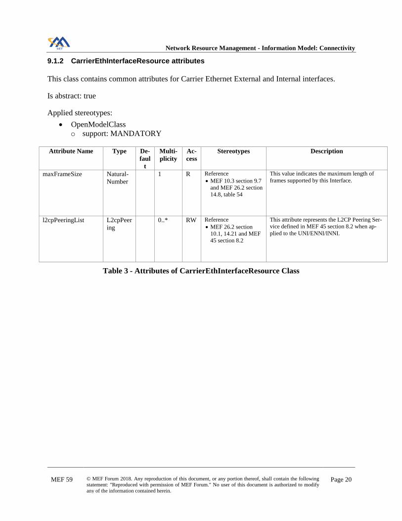
9.1.2 CarrierEthInterfaceResource attributes
This class contains common attributes for Carrier Ethernet External and Internal interfaces.
Is abstract: true
Applied stereotypes:
• OpenModelClass
o support: MANDATORY
Attribute Name Type De-
faul
t
Multi-
plicity Ac-
cess Stereotypes Description
maxFrameSize Natural-
Number 1 R Reference
• MEF 10.3 section 9.7
and MEF 26.2 section
14.8, table 54
This value indicates the maximum length of
frames supported by this Interface.
l2cpPeeringList L2cpPeer
ing 0..* RW Reference
• MEF 26.2 section
10.1, 14.21 and MEF
45 section 8.2
This attribute represents the L2CP Peering Ser-
vice defined in MEF 45 section 8.2 when ap-
plied to the UNI/ENNI/INNI.
Table 3 - Attributes of CarrierEthInterfaceResource Class

Network Resource Management - Information Model: Connectivity
MEF 59 © MEF Forum 2018. Any reproduction of this document, or any portion thereof, shall contain the following statement: "Reproduced with permission of MEF Forum." No user of this document is authorized to modify
any of the information contained herein.
Page 21
9.1.3 CarrierEthUniNResource attributes
This class represents UNI-N management function. It augments the TAPI ServiceInterfacePoint
class at the Ethernet frame layer.
Is abstract: false
Applied stereotypes:
• OpenModelClass
o support: MANDATORY
Attribute Name Type De-
faul
t
Multi-
plicity Ac-
cess Stereotypes Description
elmiPeModeEnabled Boolean 1 RW Reference
• MEF 10.3 section
9.18
This attribute denotes whether the ELMI is ena-
bled or not. When the value is TRUE, the CEN
MUST meet the mandatory requirements in
MEF 16 that apply to the UNI-N.
Note: Ethernel Local Management Interface
protocol contents are defined which clearly
identify MEF Service/Resource constructs like
UNI and EVC, hence the attribute cannot be
placed in an ethernet generic class.
_ingressBwpFlow BwpFlo
w 0..1 RW Reference
• MEF 10.3 section
9.14 and MEF 26.2
section 14.12
This attribute represents the relationship be-
tween the UNI-N and the ingress BwpFlow.
_egressBwpFlow BwpFlo
w 0..1 RW Reference
• MEF 10.3 section
9.15 and MEF 26.2
section 14.13
This attribute represents the relationship be-
tween the UNI-N and the egress BwpFlow.
Table 4 - Attributes of CarrierEthUniNResource Class
Network Resource Management - Information Model: Connectivity
MEF 59 © MEF Forum 2018. Any reproduction of this document, or any portion thereof, shall contain the following statement: "Reproduced with permission of MEF Forum." No user of this document is authorized to modify
any of the information contained herein.
Page 22
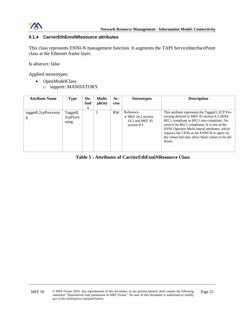
9.1.4 CarrierEthEnniNResource attributes
This class represents ENNI-N management function. It augments the TAPI ServiceInterfacePoint
class at the Ethernet frame layer.
Is abstract: false
Applied stereotypes:
• OpenModelClass
o support: MANDATORY
Attribute Name Type De-
faul
t
Multi-
plicity Ac-
cess Stereotypes Description
taggedL2cpProcessin
g TaggedL
2cpProce
ssing
1 RW Reference
• MEF 26.2 section
10.2 and MEF 45
section 8.3
This attribute represents the Tagged L2CP Pro-
cessing defined in MEF 45 section 8.3 (IEEE
802.1 compliant or 802.1 non-compliant. De-
sired to be 802.1 compliant). It is one of the
ENNI Operator Multi-lateral attributes, which
requires the CENs at the ENNI-N to agree on
the values but may allow these values to be dif-
ferent.
Table 5 - Attributes of CarrierEthEnniNResource Class

Network Resource Management - Information Model: Connectivity
MEF 59 © MEF Forum 2018. Any reproduction of this document, or any portion thereof, shall contain the following statement: "Reproduced with permission of MEF Forum." No user of this document is authorized to modify
any of the information contained herein.
Page 23
9.1.5 CarrierEthInniNResource attributes
This class represents INNI-N management function. It augments the TAPI ServiceInterfacePoint
class at the Ethernet frame layer.
Is abstract: false
Applied stereotypes:
• OpenModelClass
o support: MANDATORY
No attributes defined.

Network Resource Management - Information Model: Connectivity
MEF 59 © MEF Forum 2018. Any reproduction of this document, or any portion thereof, shall contain the following statement: "Reproduced with permission of MEF Forum." No user of this document is authorized to modify
any of the information contained herein.
Page 24
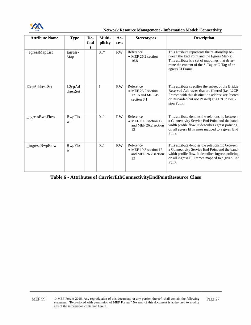
9.2 Carrier Ethernet Connectivity End Point Resource
The following diagram illustrates the NRM IM specification class representing EVC, OVC and
Service Component end points at resource level, with its attributes and associations with other
object classes.
Figure 7 - Connectivity Service End Point Diagram

Network Resource Management - Information Model: Connectivity
MEF 59 © MEF Forum 2018. Any reproduction of this document, or any portion thereof, shall contain the following statement: "Reproduced with permission of MEF Forum." No user of this document is authorized to modify
any of the information contained herein.
Page 25
9.2.1 CarrierEthConnectivityEndPointResource attributes
This class models the Carrier Ethernet Connectivity Service End Point. It augments the TAPI
ConnectivityServiceEndPoint.
Is abstract: false
Applied stereotypes:
• OpenModelClass
o support: MANDATORY
Attribute Name Type De-
faul
t
Multi-
plicity Ac-
cess Stereotypes Description
cosMappingType Co-
sOrEecM
ap-
pingType
1 RW Reference
• MEF 10.3 section
10.2 and MEF 26.2
section 16.6
The Class of Service (CoS) is used to specify
ingress Bandwidth Profiles. The CoS Mapping
Type is one of SEP (Service End Point) based,
PCP based or DSCP based.
sourceMacAddress-
Limit SourceM
acAddres
sLimit
0..1 RW Reference
• MEF 10.3 section
10.9 and MEF 26.2
section 16.15
This attribute limits the number of source MAC
Addresses that can be used in ingress EI
Frames mapped to the Connectivity Service
End Point of all types over a time interval.
When not present, the number of source MAC
addresses is unlimited.
Two independent parameters control the behav-
ior of this attribute: N : A positive integer and t
: A time interval.
This attribute operates by maintaining a list of
maximum length N of source MAC addresses
which are aged-out of the list if not seen in a
time interval t. If an ingress Service Frame ar-
rives with a new source MAC address when the
list is full, the Service Frame is discarded.
eecMappingType Co-
sOrEecM
ap-
pingType
0..1 RW Reference
• MEF 10.3 section
10.4 and MEF 26.2
section 16.9
The Egress Equivalence Class (EEC) is used to
specify Egress Bandwidth Profiles. The EEC
Mapping Type is one of SEP (Service End
Point) based, PCP based or DSCP based.
When the list of EEC Identifier is empty, this
attribute shall be unset. Otherwise it shall be
set.
_colorIdentifier ColorI-
dentifier 1 RW Reference
• MEF 10.3 section
10.3 and MEF 26.2
section 16.7
This attribute represents the relationship be-
tween the Connectivity Service End Point and a
Color Identifier.

Network Resource Management - Information Model: Connectivity
MEF 59 © MEF Forum 2018. Any reproduction of this document, or any portion thereof, shall contain the following statement: "Reproduced with permission of MEF Forum." No user of this document is authorized to modify
any of the information contained herein.
Page 26
Attribute Name Type De-
faul
t
Multi-
plicity Ac-
cess Stereotypes Description
sVlanIdList VlanIdLi
sting 0..1 RW Reference
• MEF 26.2 section
16.5.1
List of one or more S-VLAN ID values. An S-
Tagged Frame, whose S-VLAN ID value
matches an entry in this attribute, maps to the
Connectivity Service End Point.
Type=LIST: all listed VLAN IDs. Type=EX-
CEPT: all VLAN IDs except the listed ones.
Type=ALL, all VLAN IDs, hence vlanId list is
not applicable.
ceVlanIdListAndUnt
ag vlanIdLis
tAn-
dUntag
0..1 RW Reference
• MEF 10.3 section
9.10 and MEF 26.2
section 16.5.4
List of one or more C-VLAN ID values. A C-
Tagged Frame, whose C-VLAN ID value
matches an entry in this attribute, maps to the
Connectivity Service End Point.
It is possible to specify whether untagged and
priority tagged frames are included in the map-
ping.
Type=LIST: all listed VLAN IDs. Type=EX-
CEPT: all VLAN IDs except the listed ones.
Type=ALL, all VLAN IDs, hence vlanId list is
not applicable.
rootSVlanId VlanId 0..1 RW Reference
• MEF 26.2 section
16.5.2
This attribute applies only to End Points with
Trunk End Point Role. It identifies the S-
VLAN ID of frames mapped to either a Root
End Point or a Trunk End Point (via the Root
S-VLAN ID value) of the Connectivity Service.
leafSVlanId VlanId 0..1 RW Reference
• MEF 26.2 section
16.5.2
This attribute applies only to End Points with
Trunk End Point Role. It identifies the S-
VLAN ID of frames mapped to either a Leaf
End Point or a Trunk End Point (via the Leaf S-
VLAN ID value) of the Connectivity Service.
_cosIdentifierList CosIden-
tifier 1..* RW Reference
• MEF 10.3 section
10.2 and MEF 26.2
section 16.6
This attribute represents the relationship be-
tween the Connectivity Service End Point and
the Class of Service Identifier(s).
_eecIdentifierList EecIden-
tifier 0..* RW Reference
• MEF 10.3 section
10.4 and MEF 26.2
section 16.9
This attribute represents the relationship be-
tween the Connectivity Service End Point and
the Egress Equivalence Class Identifier(s).
Network Resource Management - Information Model: Connectivity
MEF 59 © MEF Forum 2018. Any reproduction of this document, or any portion thereof, shall contain the following statement: "Reproduced with permission of MEF Forum." No user of this document is authorized to modify
any of the information contained herein.
Page 27
Attribute Name Type De-
faul
t
Multi-
plicity Ac-
cess Stereotypes Description
_egressMapList Egress-
Map 0..* RW Reference
• MEF 26.2 section
16.8
This attribute represents the relationship be-
tween the End Point and the Egress Map(s).
This attribute is a set of mappings that deter-
mine the content of the S-Tag or C-Tag of an
egress EI Frame.
l2cpAddressSet L2cpAd-
dressSet 1 RW Reference
• MEF 26.2 section
12.16 and MEF 45
section 8.1
This attribute specifies the subset of the Bridge
Reserved Addresses that are filtered (i.e. L2CP
Frames with this destination address are Peered
or Discarded but not Passed) at a L2CP Deci-
sion Point.
_egressBwpFlow BwpFlo
w 0..1 RW Reference
• MEF 10.3 section 12
and MEF 26.2 section
13
This attribute denotes the relationship between
a Connectivity Service End Point and the band-
width profile flow. It describes egress policing
on all egress EI Frames mapped to a given End
Point.
_ingressBwpFlow BwpFlo
w 0..1 RW Reference
• MEF 10.3 section 12
and MEF 26.2 section
13
This attribute denotes the relationship between
a Connectivity Service End Point and the band-
width profile flow. It describes ingress policing
on all ingress EI Frames mapped to a given End
Point.
Table 6 - Attributes of CarrierEthConnectivityEndPointResource Class
Network Resource Management - Information Model: Connectivity
MEF 59 © MEF Forum 2018. Any reproduction of this document, or any portion thereof, shall contain the following statement: "Reproduced with permission of MEF Forum." No user of this document is authorized to modify
any of the information contained herein.
Page 28
9.3 Carrier Ethernet Connectivity Resource
The following diagram illustrates the NRM IM specification class representing EVC, OVC and
Service Component at resource level, with its attributes and associations with other object clas-
ses.
Figure 8 - Connectivity Service Diagram

Network Resource Management - Information Model: Connectivity
MEF 59 © MEF Forum 2018. Any reproduction of this document, or any portion thereof, shall contain the following statement: "Reproduced with permission of MEF Forum." No user of this document is authorized to modify
any of the information contained herein.
Page 29
9.3.1 CarrierEthConnectivityResource attributes
This class represents the Ethernet end to end connectivity at resource level. It may map an origi-
nal EVC, OVC, or Service Component. It augments the TAPI ConnectivityService class, which
represents the request for connectivity between two or more ConnectivityServiceEndPoint.
Is abstract: false
Applied stereotypes:
• OpenModelClass
o support: MANDATORY
Attribute Name Type Default M
ul
ti-
pl
ici
ty
Ac-
cess Stereotypes Description
multipointCapable Boolean 1 RW Reference
• MEF NRM A value of "true" indicates that the End Points
can be added/removed during Connectivity Ser-
vice lifecycle.
ceVlanPcpPreserva-
tion Boolean 1 RW Reference
• MEF 10.3 section
8.6.2 and MEF 26.2
section 12.8
This attribute can be used to preserve the value
of the CE-VLAN PCP field in VLAN Tagged
Service Frames across a Connectivity Service.
ceVlanDeiPreserva-
tion Boolean 1 RW Reference
• MEF 26.2 section
12.9
This attribute can be used to preserve the value
of the CE-VLAN DEI field in VLAN Tagged
Service Frames across a Connectivity Service.
maxFrameSize Posi-
tiveInte-
ger
1 RW Reference
• MEF 10.3 section 8.9
and MEF 26.2 section
12.6
This attribute denotes the maximum frame size
in bytes requested for the connectivity service.
ceVlanIdPreservation VlanIdPr
eserva-
tion
1 RW Reference
• MEF 10.3 section
8.6.1 and MEF 26.2
section 12.7
This attribute describes a relationship between
the format of the VLAN ID and related fields
values of the frame at one Interface and the for-
mat and VLAN ID and related fields values of
the corresponding frame at another Interface.
Used the MEF 7.3 OVC type (PRE-
SERVE/STRIP/RETAIN) as it depends on
EVC/OVC decomposition performed by SOFs.

Network Resource Management - Information Model: Connectivity
MEF 59 © MEF Forum 2018. Any reproduction of this document, or any portion thereof, shall contain the following statement: "Reproduced with permission of MEF Forum." No user of this document is authorized to modify
any of the information contained herein.
Page 30
Attribute Name Type Default M
ul
ti-
pl
ici
ty
Ac-
cess Stereotypes Description
sVlanPcpPreservation Boolean 1 RW Reference
• MEF 26.2 section
12.10
This attribute describes a relationship between
the S-VLAN PCP value of a frame at one ENNI
and the S-VLAN PCP of the corresponding
frame at another ENNI supported by the Opera-
tor CEN where each ENNI has a Connectivity
Service End Point that is associated by the Con-
nectivity Service.
sVlanDeiPreservation Boolean 1 RW Reference
• MEF 26.2 section
12.11
This attribute describes a relationship between
the S-VLAN DEI value of a frame at one ENNI
and the S-VLAN DEI of the corresponding
frame at another ENNI supported by the Opera-
tor CEN where each ENNI has a Connectivity
Service End Point that is associated by the Con-
nectivity Service.
unicastFrameDeliv-
ery FrameDe
livery-
Condi-
tion
UNCON-
DITION-
ALLY
1 RW Reference
• MEF 10.3 section 8.5
and MEF 26.2 section
12.13
When the value is conditionally, the conditions
that determine whether a Data Service Frame is
delivered or discarded MUST be specified.
Conditions can be described in the name-value
pair list.
multicastFrameDeliv-
ery FrameDe
livery-
Condi-
tion
UNCON-
DITION-
ALLY
1 RW Reference
• MEF 10.3 section 8.5
and MEF 26.2 section
12.13
When the value is conditionally, the conditions
that determine whether a Data Service Frame is
delivered or discarded MUST be specified.
Conditions can be described in the name-value
pair list.
broad-
castFrameDelivery FrameDe
livery-
Condi-
tion
UNCON-
DITION-
ALLY
1 RW Reference
• MEF 10.3 section 8.5
and MEF 26.2 section
12.13
When the value is conditionally, the conditions
that determine whether a Data Service Frame is
delivered or discarded MUST be specified.
Conditions can be described in the name-value
pair list.
_carrierEthernetSls Carri-
erEther-
netSls
0..
1 RW Reference
• MEF10.3 section 8.8
and MEF 26.2 section
12.13
This attribute presents the relationship between
a Connectivity Service and a service level spec-
ification.
Table 7 - Attributes of CarrierEthConnectivityResource Class

Network Resource Management - Information Model: Connectivity
MEF 59 © MEF Forum 2018. Any reproduction of this document, or any portion thereof, shall contain the following statement: "Reproduced with permission of MEF Forum." No user of this document is authorized to modify
any of the information contained herein.
Page 31
10 Network Resource Information Model Type Definitions
10.1 Data Types
The following data types are locally defined by NRM, i.e. are not imported from any other model.
10.1.1 FrameDeliveryCondition type
This type allows to specify conditions when the delivery type is conditionally.
Attribute Name Type Multiplicity Properties Description action DeliveryActionType 1 Data Service Frame disposition.
deliveryCondition NameAndValue 0..* When the value is conditionally, the conditions that
determine whether a Data Service Frame is delivered
or discarded MUST be specified. Conditions can be described in the name-value pair list, where name is
used to represent the condition name or identifier,
and value is used to represent the condition details associated to that name/identifier. Interoperability re-
quires further standardization.
Table 8 - FrameDeliveryCondition Data Type
10.1.2 vlanIdListAndUntag type
This type allows to specify the list of one or more C-VLAN ID values, to be considered accord-
ing to the mapping type. In addition, it is possible to specify whether untagged and priority
tagged frames are included in the mapping.
Attribute Name Type Multiplicity Properties Description vlanIdMappingType VlanIdMappingType 1 Type=LIST: all listed VLAN IDs. Type=EXCEPT:
all VLAN IDs except the listed ones. Type=ALL, all
VLAN IDs, hence vlanId list is not applicable.
untaggedAndPrioTagged-
Included Boolean 1 If true, then untagged and priority tagged frames are
included in the mapping, otherwise not.
vlanId VlanId 0..* This is for VLAN ID from 1 to 4094
Table 9 - vlanIdListAndUntag Data Type

Network Resource Management - Information Model: Connectivity
MEF 59 © MEF Forum 2018. Any reproduction of this document, or any portion thereof, shall contain the following statement: "Reproduced with permission of MEF Forum." No user of this document is authorized to modify
any of the information contained herein.
Page 32
10.2 Enumerations
The following enumeration is locally defined by NRM, i.e. is not imported from any other model.
10.2.1 DeliveryActionType type
- DISCARD
- CONDITIONALLY
- UNCONDITIONALLY
Network Resource Management - Information Model: Connectivity
MEF 59 © MEF Forum 2018. Any reproduction of this document, or any portion thereof, shall contain the following statement: "Reproduced with permission of MEF Forum." No user of this document is authorized to modify
any of the information contained herein.
Page 33
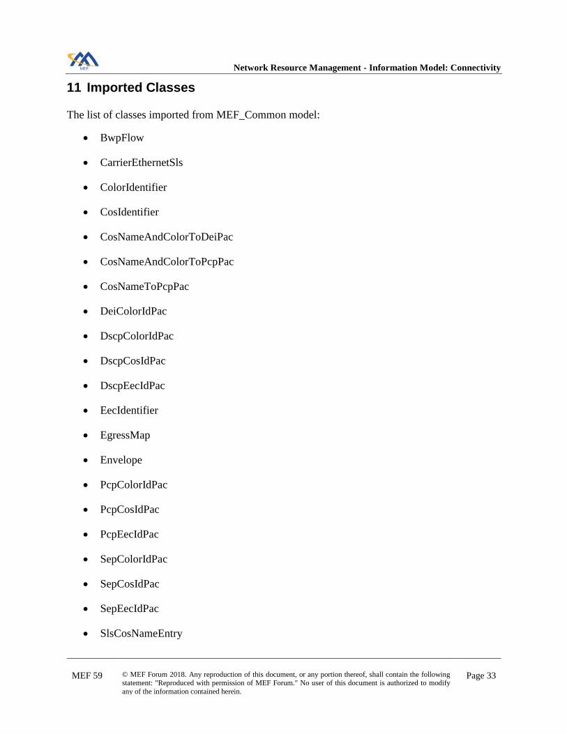
11 Imported Classes
The list of classes imported from MEF_Common model:
• BwpFlow
• CarrierEthernetSls
• ColorIdentifier
• CosIdentifier
• CosNameAndColorToDeiPac
• CosNameAndColorToPcpPac
• CosNameToPcpPac
• DeiColorIdPac
• DscpColorIdPac
• DscpCosIdPac
• DscpEecIdPac
• EecIdentifier
• EgressMap
• Envelope
• PcpColorIdPac
• PcpCosIdPac
• PcpEecIdPac
• SepColorIdPac
• SepCosIdPac
• SepEecIdPac
• SlsCosNameEntry

Network Resource Management - Information Model: Connectivity
MEF 59 © MEF Forum 2018. Any reproduction of this document, or any portion thereof, shall contain the following statement: "Reproduced with permission of MEF Forum." No user of this document is authorized to modify
any of the information contained herein.
Page 34
• SlsObjectiveAndParameters

Network Resource Management - Information Model: Connectivity
MEF 59 © MEF Forum 2018. Any reproduction of this document, or any portion thereof, shall contain the following statement: "Reproduced with permission of MEF Forum." No user of this document is authorized to modify
any of the information contained herein.
Page 35
12 Imported Type Definitions
The list of data types imported from MEF_Types model:
• ConversationIdToAggregationLinkMap
• L2cpPeering
• L2cpProtocol
• NaturalNumber
• PhysicalLayerPerLink
• PositiveInteger
• SourceMacAddressLimit
• SyncModePerLink
• VlanId
• VlanIdListing
Note: “NameAndValue” is imported from TAPI model.

Network Resource Management - Information Model: Connectivity
MEF 59 © MEF Forum 2018. Any reproduction of this document, or any portion thereof, shall contain the following statement: "Reproduced with permission of MEF Forum." No user of this document is authorized to modify
any of the information contained herein.
Page 36
The list of enumerations imported from MEF_Types model:
• CosOrEecMappingType
• FrameDelivery
• InterfaceResiliency
• L2cpAddressSet
• L2cpProtocolType
• PhysicalLayer
• TaggedL2cpProcessing
• VlanIdMappingType
• VlanIdPreservation
Network Resource Management - Information Model: Connectivity
MEF 59 © MEF Forum 2018. Any reproduction of this document, or any portion thereof, shall contain the following statement: "Reproduced with permission of MEF Forum." No user of this document is authorized to modify
any of the information contained herein.
Page 37
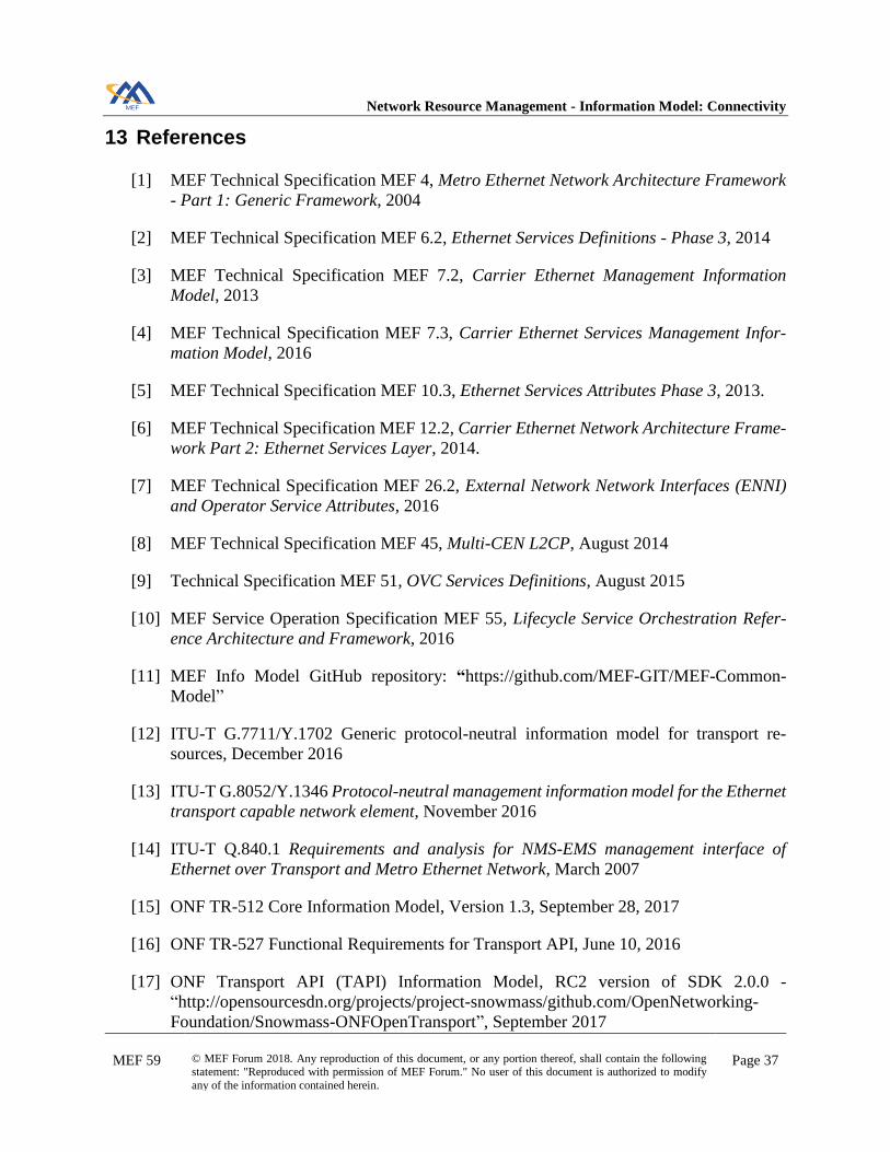
13 References
[1] MEF Technical Specification MEF 4, Metro Ethernet Network Architecture Framework
- Part 1: Generic Framework, 2004
[2] MEF Technical Specification MEF 6.2, Ethernet Services Definitions - Phase 3, 2014
[3] MEF Technical Specification MEF 7.2, Carrier Ethernet Management Information
Model, 2013
[4] MEF Technical Specification MEF 7.3, Carrier Ethernet Services Management Infor-
mation Model, 2016
[5] MEF Technical Specification MEF 10.3, Ethernet Services Attributes Phase 3, 2013.
[6] MEF Technical Specification MEF 12.2, Carrier Ethernet Network Architecture Frame-
work Part 2: Ethernet Services Layer, 2014.
[7] MEF Technical Specification MEF 26.2, External Network Network Interfaces (ENNI)
and Operator Service Attributes, 2016
[8] MEF Technical Specification MEF 45, Multi-CEN L2CP, August 2014
[9] Technical Specification MEF 51, OVC Services Definitions, August 2015
[10] MEF Service Operation Specification MEF 55, Lifecycle Service Orchestration Refer-
ence Architecture and Framework, 2016
[11] MEF Info Model GitHub repository: “https://github.com/MEF-GIT/MEF-Common-
Model”
[12] ITU-T G.7711/Y.1702 Generic protocol-neutral information model for transport re-
sources, December 2016
[13] ITU-T G.8052/Y.1346 Protocol-neutral management information model for the Ethernet
transport capable network element, November 2016
[14] ITU-T Q.840.1 Requirements and analysis for NMS-EMS management interface of
Ethernet over Transport and Metro Ethernet Network, March 2007
[15] ONF TR-512 Core Information Model, Version 1.3, September 28, 2017
[16] ONF TR-527 Functional Requirements for Transport API, June 10, 2016
[17] ONF Transport API (TAPI) Information Model, RC2 version of SDK 2.0.0 -
“http://opensourcesdn.org/projects/project-snowmass/github.com/OpenNetworking-
Foundation/Snowmass-ONFOpenTransport”, September 2017

Network Resource Management - Information Model: Connectivity
MEF 59 © MEF Forum 2018. Any reproduction of this document, or any portion thereof, shall contain the following statement: "Reproduced with permission of MEF Forum." No user of this document is authorized to modify
any of the information contained herein.
Page 38
[18] Papyrus UML Tool - Version Neon (4.6.0) “https://www.eclipse.org/papyrus/documen-
tation.html” Copyright © 2015 The Eclipse Foundation. All Rights Reserved.
[19] TM Forum, Information Framework (SID), GB922, Release 17.0.0, June 2017.
[20] TM Forum MTNM 4.5, July 2015
[21] TM Forum MTOSI 4.0, July 2015
[22] IETF RFC 6020 - YANG - A data modeling language for NETCONF
Network Resource Management - Information Model: Connectivity
MEF 59 © MEF Forum 2018. Any reproduction of this document, or any portion thereof, shall contain the following statement: "Reproduced with permission of MEF Forum." No user of this document is authorized to modify
any of the information contained herein.
Page 39
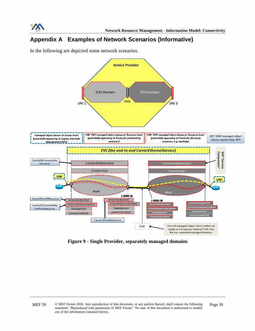
Appendix A Examples of Network Scenarios (Informative)
In the following are depicted some network scenarios.
Figure 9 - Single Provider, separately managed domains

Network Resource Management - Information Model: Connectivity
MEF 59 © MEF Forum 2018. Any reproduction of this document, or any portion thereof, shall contain the following statement: "Reproduced with permission of MEF Forum." No user of this document is authorized to modify
any of the information contained herein.
Page 40
Figure 10 - Single Provider, single managed domain, partitioning
Network Resource Management - Information Model: Connectivity
MEF 59 © MEF Forum 2018. Any reproduction of this document, or any portion thereof, shall contain the following statement: "Reproduced with permission of MEF Forum." No user of this document is authorized to modify
any of the information contained herein.
Page 41
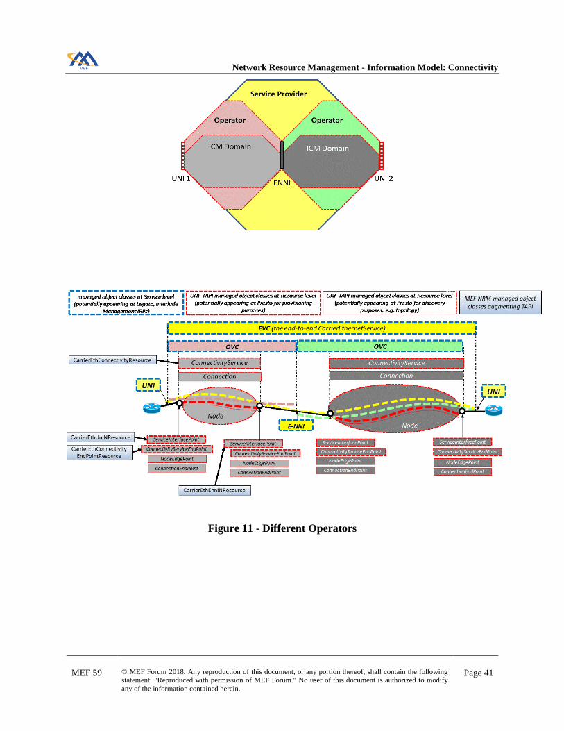
Figure 11 - Different Operators
Network Resource Management - Information Model: Connectivity
MEF 59 © MEF Forum 2018. Any reproduction of this document, or any portion thereof, shall contain the following statement: "Reproduced with permission of MEF Forum." No user of this document is authorized to modify
any of the information contained herein.
Page 42
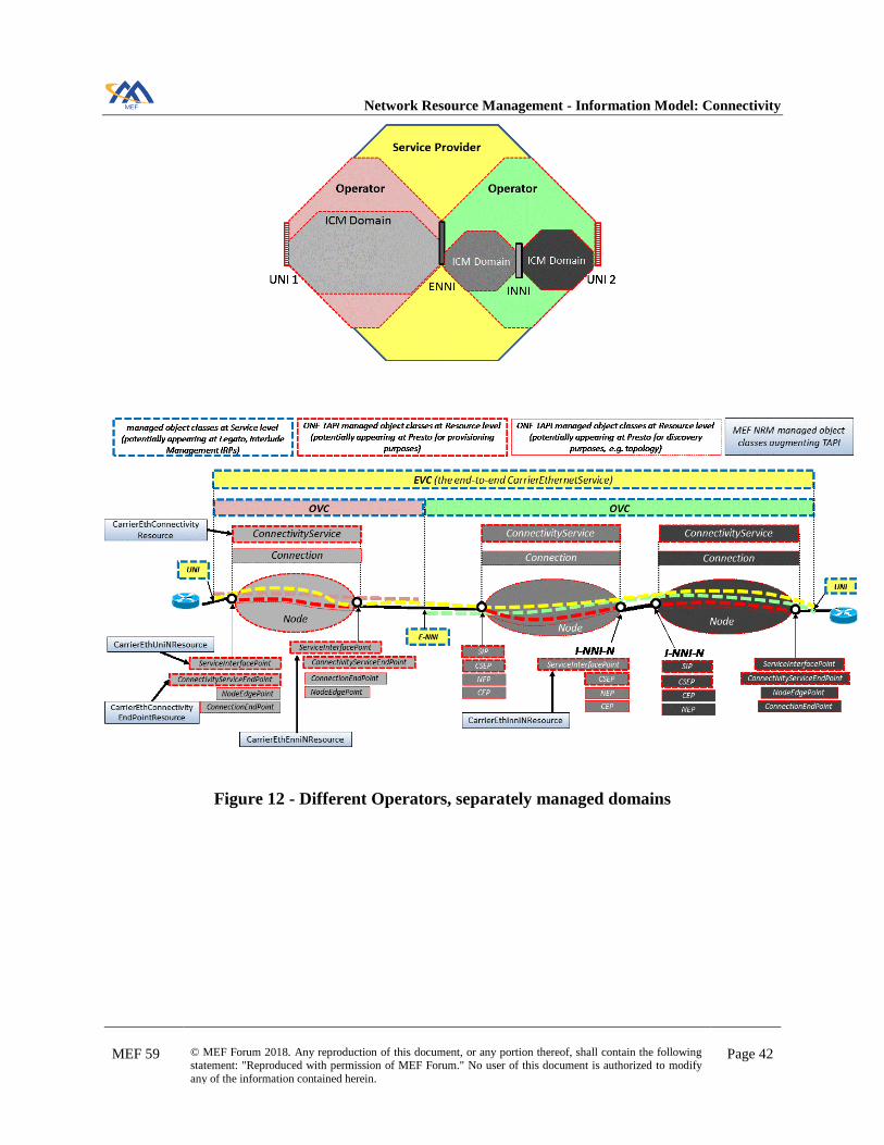
Figure 12 - Different Operators, separately managed domains
Network Resource Management - Information Model: Connectivity
MEF 59 © MEF Forum 2018. Any reproduction of this document, or any portion thereof, shall contain the following statement: "Reproduced with permission of MEF Forum." No user of this document is authorized to modify
any of the information contained herein.
Page 43
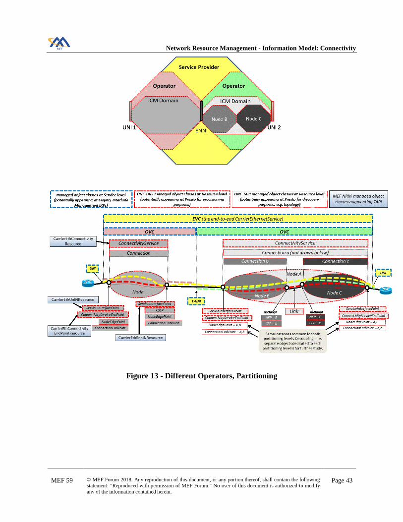
Figure 13 - Different Operators, Partitioning

Network Resource Management - Information Model: Connectivity
MEF 59 © MEF Forum 2018. Any reproduction of this document, or any portion thereof, shall contain the following statement: "Reproduced with permission of MEF Forum." No user of this document is authorized to modify
any of the information contained herein.
Page 44
Considering scenario of Figure 12, the Figure 14 describes a possible operation thread from SP
EVC Provisioning down to Connectivity Service Provisioning to Network Infrastructure.
Figure 14 - SP and two Operators: provisioning flow

Network Resource Management - Information Model: Connectivity
MEF 59 © MEF Forum 2018. Any reproduction of this document, or any portion thereof, shall contain the following statement: "Reproduced with permission of MEF Forum." No user of this document is authorized to modify
any of the information contained herein.
Page 45
Figure 15 describes a possible operation thread in case the SP A is directly managing the ICM
Domain.
Figure 15 - SP and one Operator: provisioning flow

Network Resource Management - Information Model: Connectivity
MEF 59 © MEF Forum 2018. Any reproduction of this document, or any portion thereof, shall contain the following statement: "Reproduced with permission of MEF Forum." No user of this document is authorized to modify
any of the information contained herein.
Page 46
Same as above, now considering an example of Multiple Operator Scenario (MEF 26.2 [7]).
Figure 16 - Scenario with Multiple Operators (MEF 26.2 [7])
Figure 17 - EVC/OVC/Connectivity Service

Network Resource Management - Information Model: Connectivity
MEF 59 © MEF Forum 2018. Any reproduction of this document, or any portion thereof, shall contain the following statement: "Reproduced with permission of MEF Forum." No user of this document is authorized to modify
any of the information contained herein.
Page 47
Appendix B Examples of Extension Mechanisms (Informative)
The following figures show some methods for extending the definition of the ConnectivityService
class of ONF TAPI model.
Figure 18 - Example of UML generalization
Figure 19 - Example of UML composition
Network Resource Management - Information Model: Connectivity
MEF 59 © MEF Forum 2018. Any reproduction of this document, or any portion thereof, shall contain the following statement: "Reproduced with permission of MEF Forum." No user of this document is authorized to modify
any of the information contained herein.
Page 48
Figure 20 - Example of untyped extension
Figure 21 - Example of ONF specification extension

Network Resource Management - Information Model: Connectivity
MEF 59 © MEF Forum 2018. Any reproduction of this document, or any portion thereof, shall contain the following statement: "Reproduced with permission of MEF Forum." No user of this document is authorized to modify
any of the information contained herein.
Page 49
Appendix C Mappings from MEF 7.3 to NRM (Informative)
Below an overview of MEF 7.3 [4] to NRM mappings. On the left side of the figures the MEF 7.3
[4] classes and attributes, on the right part the MEF NRM classes. Note that a yellow attribute on
the left side can be mapped either with the NRM class in same figure or with an NRM class in
another figure.
Figure 22 - UNI and ENNI at Physical Layer
elmiEnabled is defined at Ethernet UNI-N Interface level.
frameFormat: not included in resource model, as it is readonly and single-valued.
maxFrameSize, l2cpPeeringList are defined at Ethernet Interface level.
taggedL2cpProcessing is maintained at ENNI-N Interface level.
uniMegEnabled, enniMegEnabled, linkOamEnabled, lagLinkMegEnabled are not in the
scope of NRM Connectivity model.

Network Resource Management - Information Model: Connectivity
MEF 59 © MEF Forum 2018. Any reproduction of this document, or any portion thereof, shall contain the following statement: "Reproduced with permission of MEF Forum." No user of this document is authorized to modify
any of the information contained herein.
Page 50
Figure 23 - UNI (Frame Aggregation Layer)
uniMegEnabled is not in the scope of NRM Connectivity model.
untaggedAndPriorityTaggedCeVlanId, defaultCeVlanId can be replaced by enhancing the
ceVlanIdList of CarrierEthConnectivityEndPointResource to allow the indication that un-
tagged and priority-tagged frames are mapped to this end point.
tokenShareEnabled is redundant, as it is “enabled” when more
CarrierEthConnectivityEndPointResource point to same Envelope (through BwpFlow).
_envelopeList: Envelopes are already referenced by BwpFlow.
l2cpAddressSet is moved to CarrierEthConnectivityEndPointResource.

Network Resource Management - Information Model: Connectivity
MEF 59 © MEF Forum 2018. Any reproduction of this document, or any portion thereof, shall contain the following statement: "Reproduced with permission of MEF Forum." No user of this document is authorized to modify
any of the information contained herein.
Page 51
serviceProviderUniId: this attribute is an example of management information which likely
does not need to be provisioned down to infrastructure. At most, it could help ICM, EML GUI
users to map pure resource view with service view.
maxNumOfEvcs: not necessary at NRM level, SOF can enforce it.
bundlingEnabled, serviceMultiplexingEnabled, allToOneBundlingEnabled: not necessary at
NRM level, SOF can enforce appropriate multiplicity of objects.
maxNumOfCeVlanIdPerOvcEndPoint: not necessary at NRM level, SOF can enforce it.
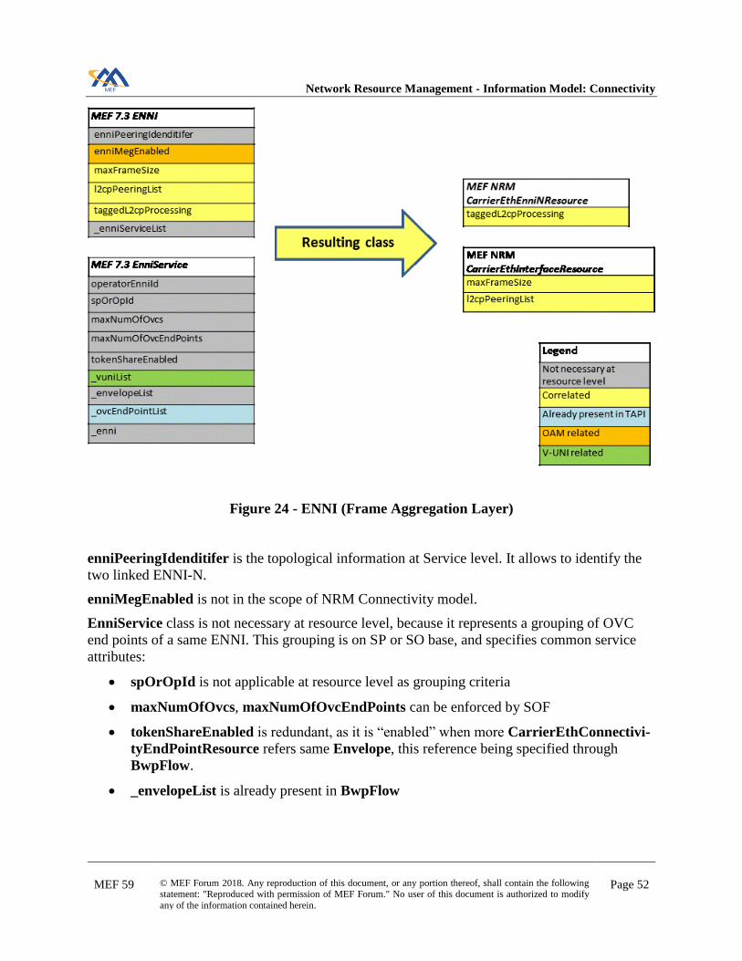
Network Resource Management - Information Model: Connectivity
MEF 59 © MEF Forum 2018. Any reproduction of this document, or any portion thereof, shall contain the following statement: "Reproduced with permission of MEF Forum." No user of this document is authorized to modify
any of the information contained herein.
Page 52
Figure 24 - ENNI (Frame Aggregation Layer)
enniPeeringIdenditifer is the topological information at Service level. It allows to identify the
two linked ENNI-N.
enniMegEnabled is not in the scope of NRM Connectivity model.
EnniService class is not necessary at resource level, because it represents a grouping of OVC
end points of a same ENNI. This grouping is on SP or SO base, and specifies common service
attributes:
• spOrOpId is not applicable at resource level as grouping criteria
• maxNumOfOvcs, maxNumOfOvcEndPoints can be enforced by SOF
• tokenShareEnabled is redundant, as it is “enabled” when more CarrierEthConnectivi-
tyEndPointResource refers same Envelope, this reference being specified through
BwpFlow.
• _envelopeList is already present in BwpFlow

Network Resource Management - Information Model: Connectivity
MEF 59 © MEF Forum 2018. Any reproduction of this document, or any portion thereof, shall contain the following statement: "Reproduced with permission of MEF Forum." No user of this document is authorized to modify
any of the information contained herein.
Page 53
Figure 25 - EVC/OVC End Point
adminState, operationalState, userLabel already defined in TAPI.
evcEndPointMap is mapped by CE VLAN ID list.
_ovcEndPointMap is replaced by CE/S/root/leaf VLAN ID lists.
UNI defaultCeVlanId can be replaced by enhancing the ceVlanIdList to allow the indication
that untagged and priority-tagged frames are mapped to this end point.
subscriberMegMipEnabled, mipEnabled, mepList, testMegEnabled are not in the scope of
NRM Connectivity model.
aggLinkDepthList not applicable at resource management level because conversationID to Ag-
gregation Link Map would always be known.

Network Resource Management - Information Model: Connectivity
MEF 59 © MEF Forum 2018. Any reproduction of this document, or any portion thereof, shall contain the following statement: "Reproduced with permission of MEF Forum." No user of this document is authorized to modify
any of the information contained herein.
Page 54
Figure 26 - EVC, OVC
adminState, operationalState, serviceState, userLabel, connectionType already defined in
TAPI.
multipointCapable attribute is added to describe connectivity service capability to add/remove
end points.
unicastFrameDelivery, multicastFrameDelivery, broadcastFrameDelivery: type enhanced
with a name-value pair list, to allow specification of conditions.
ceVlanIdPreservation, ceVlanPcpPreservation, ceVlanDeiPreservation, sVlanPcpPreserva-
tion, sVlanDeiPreservation may be not applicable in case of not Ethernet INNIs – i.e. “transit”
domains transparently supporting Ethernet. Note that in an Ethernet transit domain the infor-
mation is necessary in case a new end point is added (hence domain moves from “transit” to “ac-
cess”).
availableMegLevel is not in the scope of NRM Connectivity model.
ovcL2cpAddressSet: centralized in CarrierEthConnectivityEndPointResource.
maxNumOfEvcEndPoint, maxNumOfUniOvcEndPoints, maxNumOfEnniOvcEndPoints:
not necessary at NRM level, SOF can enforce them.

Network Resource Management - Information Model: Connectivity
MEF 59 © MEF Forum 2018. Any reproduction of this document, or any portion thereof, shall contain the following statement: "Reproduced with permission of MEF Forum." No user of this document is authorized to modify
any of the information contained herein.
Page 55

Network Resource Management - Information Model: Connectivity
MEF 59 © MEF Forum 2018. Any reproduction of this document, or any portion thereof, shall contain the following statement: "Reproduced with permission of MEF Forum." No user of this document is authorized to modify
any of the information contained herein.
Page 56
Appendix D Summary Table of Classes (Informative)
Table 10 - Summary Table of Managed Object Classes