Embed Size (px)
Citation preview

Introduction to NetworksNetworking Components
Installation of Network Hardware Planning a Network Topology
Planning Network ConnectionsNetwork Troubleshooting
Culminating Task (Summative)
Including:
March 2005
Written by: David Keffer
NetworkingNetwork components, Types and
Topologies
Length of Unit: approximately: 20 hours
A Unit for Grade 11
Written using the Ontario Curriculum Unit Planner 3.0.1R PLNR2002R Official Version, Runtime Open Printed on 10 Mar, 2005 at 4:38:52 PM

NetworkingNetwork components, Types and Topologies A Unit for Grade 11
David Keffer
David Keffer
University of Ontario Institute of Technology(905)721-3111Durham Region
University of Ontario Institute of Technology+1 (905) 721-2000
Based on a unit by:
A Unit for Grade 11Written by:
This unit was written using the Curriculum Unit Planner, 1999-2002, which was developed in the province of Ontario by theMinistry of Education. The Planner provides electronic templates and resources to develop and share units to help implement theOntario curriculum. This unit reflects the views of the developers of the unit and is not necessarily those of the Ministry ofEducation. Permission is given to reproduce this unit for any non-profit educational purpose. Teachers are encouraged to copy,edit, and adapt this unit for educational purposes. Any reference in this unit to particular commercial resources, learningmaterials, equipment, or technology does not reflect any official endorsements by the Ministry of Education, school boards, orassociations that supported the production of this unit.
Written using the Ontario Curriculum Unit Planner 3.0.1R PLNR2002R Official Version, Runtime Open Printed on 10 Mar, 2005 at 4:38:52 PM

Networking Page 1
Network components, Types and Topologies A Unit for Grade 11
Unit Overview
Unit ContextThis unit will allow students to develop the necessary skills to recognize and install networking hardware andsoftware components, and to connect computers to construct a functioning network. During this process,they will use a variety of research and problem solving techniques, and will apply these to the troubleshootingof network malfunctions that arise.
Unit SummaryIn this unit, students identify and explore network components, network types, and topologies, and applynetworking concepts to design network configurations. The use of proper terminology (e.g., logical andphysical topologies, standards) and the development of effective solutions to given situations are keycomponents of this unit. Students use problem-solving skills to apply their knowledge to tasks such asinstalling network cards and activating the operating system. They create a computer network, based on ananalysis of system requirements, installing the required network interface cards, operating systems, driversand other software. They select and configure appropriate networking protocols, and then perform a varietyof troubleshooting procedures. Students learn about the importance of network connectivity andinfrastructure and how it impacts on our world as well as potential career opportunities in the area ofcomputer networking.
Culminating Task AssessmentAs a culminating task for this unit, students will create a simple network consisting of two computers.Students will install network adaptor cards into working computer systems, build the required networkingcables, and physically connect the two computers in a star network topology using a hub. Students will thenconfigure the operating system to connect the two computers in a peer-to-peer network, with file and printsharing, and troubleshoot any problems that arise. Students will maintain a log during the construction of thenetwork, and will submit this with a report detailing the construction, including photographs and diagrams.
Links to Prior KnowledgeStudents have already completed a unit in computer hardware, software and operating systems. They havelearned to identify and explain the functions of basic components of a typical computer, including its internalcomponents and peripheral devices. Using this knowledge, they have disassembled/assembled andupgraded computer hardware. They have also installed an operating system (OS) and drivers to configureand optimize the computer hardware they have assembled. Through these hardware and software activities,they have learned to recommend a computer system based on exacting requirements. Upon completion ofthese activities, students were able to place hardware and software developments in an historicalperspective.Emphasis was placed on safety as students handled a variety of internal and external components. Inaddition, a database of hardware components, logs of system changes and upgrades as well as a log ofterminology was created by students to assist them in accurately defining terms and listing hardwaremanagement techniques.
ConsiderationsTECHNOLOGYCAREER EDUCATIONHEALTH AND SAFETY
Written using the Ontario Curriculum Unit Planner 3.0.1R PLNR2002R Official Version, Runtime Open Printed on 10 Mar, 2005 at 4:39:00 PM

Networking Page 2
Network components, Types and Topologies A Unit for Grade 11
Unit Overview
LIBRARY / INFORMATION CENTRE
Accommodations:
Teachers should consult individual student IEPs for specific direction on accommodation for individuals. Thefollowing accommodation strategies can be used in the activities throughout the unit. Specific strategiesrelating to course content are given in each activity.
Assessment Accommodations· Provide additional review for students having difficulty integrating all the structures.· Allow for non-timed evaluations.· Ensure that students understand assessment/evaluation tools.· Provide the option for oral testing and demonstrations of skills.· Provide for alternative displays of achievement, such as oral testing, taped answers, and scribing forstudents with writing difficulties.
Enrichment· Organize more advanced problems (design work, research paper, alternate interfacing projects).· Appoint students as assistant site administrators.
Physical Accommodations· Check to ensure all aids, environmental issues, safety precautions, and assistance for students toachieve success are in place.· Provide appropriate adaptive devices, e.g., large screen monitors, touch screens, etc.· Provide support for hands-on sessions.· Most computer peripherals can be adapted to accommodate physical impairments.
Instructional Accommodations· Provide peer tutoring.· Provide flexible timelines.· Encourage small-group learning.· Facilitate student-to-student discussion and teacher-to-student discussion to encourage confidenceand motivation.· Provide written materials for students having difficulty processing auditory information.· Provide handouts to reinforce demonstrations.· Provide clarification to students of assessment/evaluation tools such as rubrics and checklists.
[From the course profile.]
Notes to TeacherSince most of the unit deals with hands-on network planning and implementation, the instructor should havesome considerable experience with these topics. Without this, the instructor will not be able to competentlydeal with troubleshooting of problems which will certainly occur.
Written using the Ontario Curriculum Unit Planner 3.0.1R PLNR2002R Official Version, Runtime Open Printed on 10 Mar, 2005 at 4:39:00 PM

NetworkingNetwork components, Types and Topologies A Unit for Grade 11
Subtask List Page 1List of Subtasks
Introduction to NetworksThis initial subtask provides students with an introduction to the general concepts of local areanetworks. During the task, they will gain an introductory understanding of the main concepts ofnetworking, including networking hardware and software, network topologies and types, and hownetworks connect to share data and resources. This introduction will prepare students for moredetailed exploration in later subtasks.
1
Networking ComponentsIn this subtask, students will now look in more detail at the different hardware and softwarecomponents of a local area network. They will examine each component's role in the network, and howthe components physically connect to form the network. Students will research networking componentsindividually or in pairs, and will then present the results of their research to the class. This will befollowed by a class discussion.
2
Installation of Network Hardware Students will now apply their knowledge of network hardware components by installing networkinterface cards, and the required software drivers for the network components, and constructing andtesting network cables. They will also learn to connect computers together into a small network, andconfigure the operating software to allow file and resource sharing. This will be accompanied by anintroduction to troubleshooting, using either real or simulated problems. Students will work in pairs orsmall groups. Installation and troubleshooting exercises will be followed by class discussion.
3
Planning a Network TopologyUpon reaching this unit, students should be familiar with network components and standards. They willnow learn how to properly design a network topology, or physical layout, based on the requirements ofa particular scenario. This learning will be reinforced with example topology design projects. Studentswill work on these projects in pairs or small groups, and each project will be followed by classdiscussion.
4
Planning Network ConnectionsThis subtask is an extension of the previous one, in which students will plan the physical wiring ofnetworks. Students will work to extend their topology planning of the previous subtask, to completetheir network planning projects. Example projects will include both new network installations andextensions to existing networks. Students will work on projects in pairs or small groups, and planningexercises will be followed by class discussion.
5
Network TroubleshootingIn this subtask, students will look at a variety of different problems which can occur in networks. Theywill examine how to recognize the source of the problem, and how best to resolve it. Learning will takeplace using a number of example problems, both real and simulated. Students will work on thetroubleshooting exercises in pairs or small groups, and exercises will be followed by class discussion.
6
Culminating Task (Summative)As a culminating task for this unit, students will create a simple network consisting of two computers.Students will install network adaptor cards into working computer systems, build the requirednetworking cables, and physically connect the two computers in a star network topology using a hub.Students will then configure the operating system to connect the two computers in a peer-to-peernetwork, with file and print sharing, and troubleshoot any problems that arise. Students will maintain alog during the construction of the network, and will submit this with a report detailing the construction,including photographs and diagrams.
7
Written using the Ontario Curriculum Unit Planner 3.0.1R PLNR2002R Official Version, Runtime Open Printed on 10 Mar, 2005 at 4:39:03 PM

NetworkingNetwork components, Types and Topologies
Resource List
A Unit for Grade 11
Page 1
Blackline Master / FileCulminating Task
culminating task.docCulminating summative assessed task for the unit.
ST 7
Culminating Task Rubricculminating task rubric.docThis is a rubric for evaluation of the culminating task.
ST 7
Making 100BaseT Cablesmaking cables.pptInstructions for constructing 100BaseT unshieldedtwisted-pair cables.
ST 3
Network Components Exercisenetwork components exercise.docThis exercise has students researching the role of differenthardware and software components in a network. Studentswork either individually or in pairs, and present the resultsof their research to the class in the next lesson.
ST 2
Network Terminology Quiznetwork terminology quiz.docQuiz on network terminology.
ST 1
Network Topology Planning Exercise #1planning exercise 1.docNetwork topology planning exercise.
ST 4
Network Topology Planning Exercise #1planning exercise 1.pptNetwork topology planning exercise.
ST 4
Network Topology Planning Exercise #1planning exercise 1.jpgNetwork topology planning exercise.
ST 4
Network Topology Planning Exercise #2planning exercise 2.docNetwork topology planning exercise.
ST 5
Network Topology Planning Exercise #2planning exercise 2.pptNetwork topology planning exercise.
ST 5
Network Topology Planning Exercise #2planning exercise 2a.jpgNetwork topology planning exercise.
ST 5
Network Topology Planning Exercise #2planning exercise 2b.jpgNetwork topology planning exercise.
ST 5
Network Topology Planning Exercise #2planning exercise 2c.jpgNetwork topology planning exercise.
ST 5
Network Troubleshooting Exercise - Instructortroubleshooting teacher.docInstructors version of a network troubleshooting exercise.
ST 6
Network Troubleshooting Exercise - Studenttroubleshooting student.docStudent version of a network troubleshooting exercise.
ST 6
Networking: A PrimerNetwork Primer.pdfBasic networking primer from Bay Networks. This is a bitout of date, but still has much useful information andterminology.
ST 1
Networking Components Rubricnetwork components rubric.docRubric for networking components excercise.
ST 2
Planning Exercise Rubricplanning exercise rubric.docRubric for network topology and connections planningexercise.
ST 4
Planning Exercise Rubricplanning exercise rubric.docRubric for network topology and connections planningexercise.
ST 5
Topology Quiztopology quiz.docNetwork topology quiz.
ST 4
Troubleshooting a Network Connectiontroubleshoot network.docHow to troubleshoot a network connection.
ST 6
Windows XP Network Protocolswinxp protocols.docAn article from Practically Networked / EarthWeb onWindows XP network protocols. This is a good primer onnetwork protocols.
ST 2
Written using the Ontario Curriculum Unit Planner 3.0.1R PLNR2002R Official Version, Runtime Open Printed on 10 Mar, 2005 at 4:39:06 PM

NetworkingNetwork components, Types and Topologies
Resource List
A Unit for Grade 11
Page 2
Licensed SoftwareCorel WordPerfect Suite 8 Academic UnitCorelDRAW 8 Academic UnitMicrosoft Works V3.0 (English) Unit
PrintCore MCSE: Networking Essentials
Keogh, JimISBN 0130107336
Unit
Intelligent Networks: Basic Technology,Standards & Evolution
Magendanz, Thomas and Radu Popescu-ZeletinISBN 1850322937
Unit
Sams Teach Yourself Windows Networking in 24Hours
Kearns, DaveISBN 0672314754
Unit
Windows Networking BasicsGregg, KennethISBN 0764532146
Unit
Website3Com's NetPrep Program
http://education.3com.com/Netprep/index.htmlUnit
Assembling Patch Cableshttp://www.startech.com/structuredwiring/patchcable.htm
Unit
Cisco Certification CCIEhttp://www.cisco.com/warp/public/625/ccie/
Unit
Network Design and Research Centrehttp://www.alaska.net/~research/Net/tutorial.htm
Unit
Network Tutorialshttp://www.wizard.com/users/baker/public_html/NetTutor.html
Unit
Novell Network Primerhttp://www.novell.com/catalog/primer/primer.html
Unit
Various Networking Tutorials and Informationhttp://compnetworking.about.com
Unit
Webopediahttp://www.webopedia.com
Unit
Written using the Ontario Curriculum Unit Planner 3.0.1R PLNR2002R Official Version, Runtime Open Printed on 10 Mar, 2005 at 4:39:06 PM

NetworkingNetwork components, Types and Topologies
Resource List
A Unit for Grade 11
Page 3
MaterialBasic Computer System
1
These should be computer systems that have beenassembled by the students during the previous unit.
per pair
Unit
Cable Stripper and Crimper4per class
Unit
Cable Tester1per class
Unit
Computer System with Internet Access1per person
Unit
Network Cabling and ConnectorsUnshielded twisted-pair cabling and RJ-45 connectors, inbulk, as required.
Unit
Network Interfact Card1
With driver software.per person
Unit
Networked Laser Printer1per class
Unit
OtherMicrosoft Office XP Professional
SoftwareUnit
Microsoft Windows 98Software - Operating System
Unit
Microsoft Windows XP ProfessionalSoftware - Operating System
Unit
Written using the Ontario Curriculum Unit Planner 3.0.1R PLNR2002R Official Version, Runtime Open Printed on 10 Mar, 2005 at 4:39:06 PM

Expectation List
Selected
NetworkingNetwork components, Types and Topologies A Unit for Grade 11
Page 1
Assessed
Computer Engineering---Theory and Foundation
· identify the function and interaction of basic computer components and peripherals; 1TFV.01· describe the relationship among computer hardware, networks, and operating systems; 5TFV.02– identify differences between stand-alone and network hardware; 5TF2.03– describe similarities and differences between network and desktop operating systems. 1TF2.04
Computer Engineering---Skills and Processes· properly install and configure key computer hardware and software components; 3SPV.03· use network services to facilitate intranetworking among workstations. 2SPV.04– properly install and configure key software and hardware components and peripherals; 1SP2.03– properly install and configure a workstation operating system, including a network connection; 3SP2.04– properly implement standard network protocols for file transfer. 1SP2.07
Computer Engineering---Impact and Consequences– describe issues that arise from the growing use of networked systems (e.g., complexity, compatibility, security); 3IC1.03
Computer Engineering---Theory and Foundation· describe computer networks and operating systems; 3TFV.02
Written using the Ontario Curriculum Unit Planner 3.0.1R PLNR2002R Official Version, Runtime Open Printed on 10 Mar, 2005 at 4:39:09 PM
NetworkingNetwork components, Types and Topologies
Expectation Summary
ICE 3MSelected Assessed
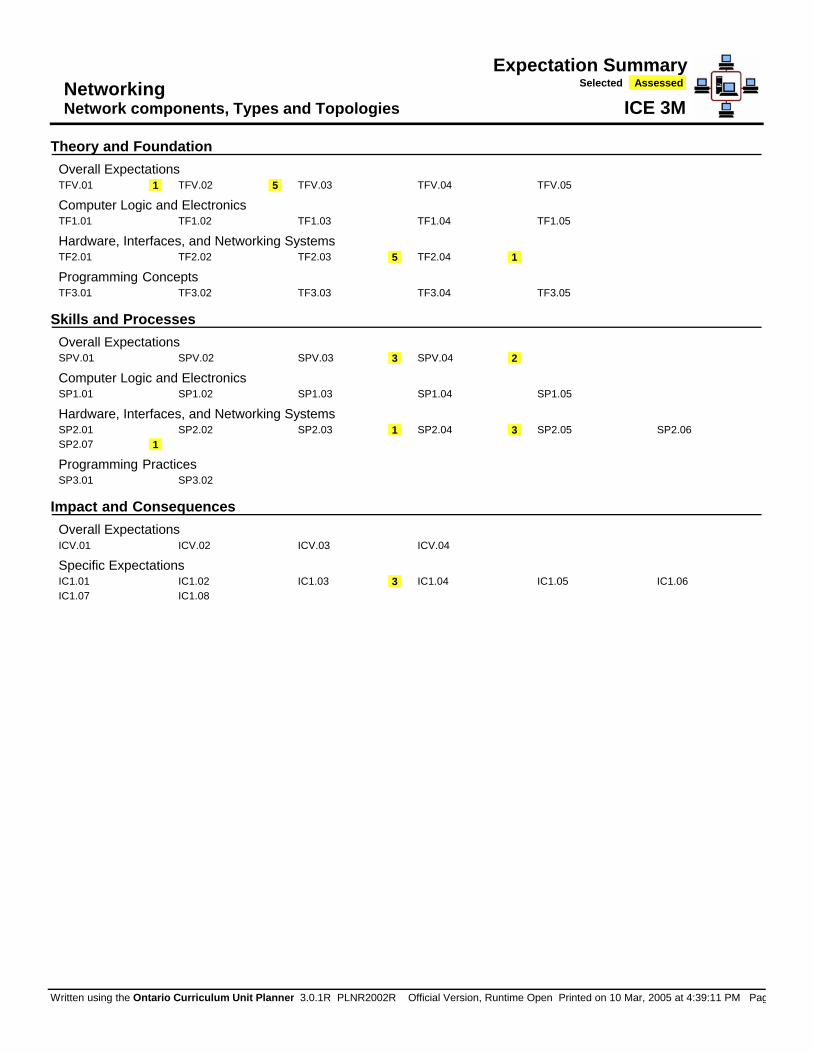
Theory and FoundationOverall ExpectationsTFV.01 1 TFV.02 5 TFV.03 TFV.04 TFV.05
Computer Logic and ElectronicsTF1.01 TF1.02 TF1.03 TF1.04 TF1.05
Hardware, Interfaces, and Networking SystemsTF2.01 TF2.02 TF2.03 5 TF2.04 1
Programming ConceptsTF3.01 TF3.02 TF3.03 TF3.04 TF3.05
Skills and ProcessesOverall ExpectationsSPV.01 SPV.02 SPV.03 3 SPV.04 2
Computer Logic and ElectronicsSP1.01 SP1.02 SP1.03 SP1.04 SP1.05
Hardware, Interfaces, and Networking SystemsSP2.01 SP2.02 SP2.03 1 SP2.04 3 SP2.05 SP2.06SP2.07 1
Programming PracticesSP3.01 SP3.02
Impact and ConsequencesOverall ExpectationsICV.01 ICV.02 ICV.03 ICV.04
Specific ExpectationsIC1.01 IC1.02 IC1.03 3 IC1.04 IC1.05 IC1.06IC1.07 IC1.08
Written using the Ontario Curriculum Unit Planner 3.0.1R PLNR2002R Official Version, Runtime Open Printed on 10 Mar, 2005 at 4:39:11 PM Pag

NetworkingNetwork components, Types and Topologies A Unit for Grade 11
Page 1Unit Analysis
Assessment Recording Devices
7 Rubric
Assessment Strategies
5 Classroom Presentation1 Exhibition/demonstration5 Learning Log5 Performance Task2 Quiz, Test, Examination1 Self Assessment
Groupings
6 Students Working As A Whole Class6 Students Working In Pairs4 Students Working In Small Groups3 Students Working Individually
Teaching / Learning Strategies
4 Demonstration6 Discussion3 Independent Study5 Internet Technologies1 Lecture5 Problem Solving1 Report1 Research Process3 Technical Design Process
Analysis Of Unit Components
7 Subtasks 28 Expectations 47 Resources 74 Strategies & Groupings
-- Unique Expectations -- 11 Technological Education
Resource Types
0 Rubrics 3 Blackline Masters 3 Licensed Software 4 Print Resources 0 Media Resources 8 Websites 7 Material Resources 0 Equipment / Manipulatives 0 Sample Graphics 3 Other Resources 0 Parent / Community 0 Companion Bookmarks
Written using the Ontario Curriculum Unit Planner 3.0.1R PLNR2002R Official Version, Runtime Open Printed on 10 Mar, 2005 at 4:39:15 PM

Networking Subtask 1Introduction to Networks
Network components, Types and Topologies A Unit for Grade 11 ~ 1.25 hours
ExpectationsTFV.02 A · describe the relationship among computer
hardware, networks, and operating systems;TF2.03 A – identify differences between stand-alone and
network hardware;TFV.02 A · describe computer networks and operating
systems;
DescriptionThis initial subtask provides students with an introduction to the general concepts of local area networks.During the task, they will gain an introductory understanding of the main concepts of networking, includingnetworking hardware and software, network topologies and types, and how networks connect to share dataand resources. This introduction will prepare students for more detailed exploration in later subtasks.
GroupingsStudents Working IndividuallyStudents Working In PairsStudents Working As A Whole Class
Teaching / Learning StrategiesLectureDiscussionIndependent StudyInternet Technologies
AssessmentStudents will learn the basic concepts ofnetworking. These will be assessed by aformative quiz.
Assessment StrategiesQuiz, Test, Examination
Assessment Recording DevicesRubric
Resources
Teaching / LearningStudents will learn the general concepts of local area networks through a process of lecture, independent study,and class discussion.
AdaptationsSee the Unit Overview under Considerations for general accommodations.
Network Terminology Quiz network terminology quiz.doc
Networking: A Primer Network Primer.pdf
Written using the Ontario Curriculum Unit Planner 3.0.1R PLNR2002R Official Version, Runtime Open Printed on 10 Mar, 2005 at 5:46:55 PM PageC-__

Networking Subtask 1Introduction to Networks
Network components, Types and Topologies A Unit for Grade 11 ~ 1.25 hours
Notes to TeacherThis subtask provides students with a basic understanding of networking terminology and concepts. Learning isreinforced with a formative quiz.
Teacher Reflections
Written using the Ontario Curriculum Unit Planner 3.0.1R PLNR2002R Official Version, Runtime Open Printed on 10 Mar, 2005 at 5:46:55 PM PageC-__

The World of Computer Networking
In the last 15 years, LANs have gone
from being an experimental technology
to becoming a key business tool used
by companies worldwide.
White Paper Networking: A Primer

2 White Paper Networking: A Primer
In the last 15 years, LANs have gone frombeing an experimental technology tobecoming a key business tool used by companies worldwide. A LAN is a high-speed communications system designed tolink computers and other data processingdevices together within a small geographicarea such as a workgroup, department,or a single floor of a multistory building.Several LANs can also be interconnectedwithin a building or campus of buildings to extend connectivity.
Some Background on LANs
LANs have become popular because theyallow users to share vital computingresources electronically, including expensivehardware such as printers and CD-ROM drives, application programs, and, mostimportantly, the information the users needto do their jobs. Prior to the development of LAN technology, individual computerswere isolated from each other and limited in their range of applications. By linkingthese individual computers over LANs, theirusefulness and productivity have beenincreased enormously. But a LAN by its verynature is a local network, confined to a fairlysmall area such as a building or even a singlefloor of a building. To realize the full benefitof computer networking, it is critical to linkthe individual LANs into an enterprise-widebackbone network that connects all of thecompany’s employees and computingresources, no matter how geographically dispersed they may be.
Today’s LANs and LAN internetworks arepowerful, flexible, and easy to use, but theyincorporate many sophisticated technologiesthat must work together flawlessly. For aLAN to really benefit an organization it mustbe designed to meet the organization’schanging communications requirements.Building a LAN is a process of choosing different pieces and matching them togeth-er. This primer is designed to help first-timeLAN equipment buyers and users under-stand the fundamentals of how LANs oper-ate, what the different technology choicesare for building a LAN, and the ramificationsof choosing one option over another. Alsodiscussed is the concept of internetworkingor connecting disparate and geographicallydispersed LANs together to form an enter-prise system, the different technologies andproducts available to do so, and the benefitsand limitations of each.
To aid readers unfamiliar with networkingterminology, terms in boldface appear in aGlossary in the back of this primer.
The World of Computer Networking
Figure 1 A Basic LAN Bus Network
When Station B sends a packet to another station onthe LAN, it passes by all of the stations connected tothat LAN. On the bus network illustrated here, theelectrical signal representing the packet travels awayfrom the sending station in both directions on theshared cable. All stations will see the packet, but onlythe station it is addressed to will pay attention to it. Packet
Station A Station B Station C Station D

The Basics of Local Area Networking
Today local area networking is a shared
access technology. This means that all of thedevices attached to the LAN share a single communications medium, usually acoaxial, twisted pair, or fiber optic cable.Figure 1 illustrates this concept: Several computers are connected to a single cablethat serves as the communications mediumfor all of them. The physical connection to thenetwork is made by putting a network
interface card (NIC) inside the computer andconnecting it to the network cable. Oncethe physical connection is in place, it is up tothe network software to manage communi-cations between stations on the network.
In a shared media network, when one stationwishes to send a message to another station it uses the software in the workstationto put the message in an “envelope.” Thisenvelope, called a packet, consists of messagedata surrounded by a header and trailer
that carry special information used by thenetwork software to the destination station.One of the pieces of information placed in the packet header is the address of the destination station.
The NIC then transmits the packet onto theLAN. The packet is transmitted as a streamof data bits represented by changes in elec-trical signals. As it travels along the sharedcable, all of the stations attached to it see thepacket. As it goes by the NIC in each station,the NIC checks the destination address inthe packet header to determine if the packetis addressed to it. When the packet passesthe station it is addressed to, the NIC at thatstation copies the packet and then takes the data out of the envelope and gives it tothe computer.
Figure 1 shows one source station sending a single message packet to one destinationstation. If the message the source stationwants to send is too big to fit into one packet,it will send the message in a series of packets. On a shared access LAN, however,many stations all share the same cable.
Since each individual packet is small, it takesvery little time to travel to the ends of thecable where the electrical signal dissipates.So after a packet carrying a messagebetween one pair of stations passes alongthe cable, another station can transmit apacket to whatever station it needs to senda message. In this way, many devices canshare the same LAN medium.
Ethernet
The most widely used LAN technology inuse today is Ethernet. It strikes a good balance between speed, price, ease of installation, and supportability. Approximately80 percent of all LAN connections installeduse Ethernet.
The Ethernet standard is defined by theInstitute of Electrical and ElectronicsEngineers (IEEE) in a specification commonlyknown as IEEE 802.3. The 802.3 specificationcovers rules for configuring Ethernet LANs,the types of media that can be used, and howthe elements of the network should interact.The Ethernet protocol provides the servicescalled for in the Physical and Data LinkLayers of the OSI reference model (pleaserefer to the “Standards and Protocols” sidebar).
One element of the 802.3 specificationstates that Ethernet networks run at a datarate of 10 million bits per second (10 Mbps)or 100 million bits per second (100 Mbps) in the case of Fast Ethernet. This means thatwhen a station transmits a packet onto the Ethernet medium it travels along thatmedium at 10 Mbps.
Another important element defined by the 802.3 specification is the access methodto be used by stations connected to an
Ethernet LAN, called carrier sense multiple
access with collision detection (CSMA/CD).In this method, each station contends foraccess to the shared medium. It is possiblefor two stations to try sending packets at the same time, which results in a collision
on the LAN. In Ethernet networks, collisionsare considered normal events and theCSMA/CD access method is designed toquickly restore the network to normal activity after a collision occurs.
Ethernet Media and Topologies An importantpart of designing and installing a LAN isselecting the appropriate medium andtopology for the environment. Ethernet networks can be configured in either a staror bus topology and installed using any ofthree different media.
Coaxial cable was the original LAN mediumand it is used in what is called a bus topology
(see Figure 1 for a typical bus topology).In this configuration, the coaxial cable formsa single bus to which all stations are attached.This topology is rarely used in new LANinstallations today because it is relatively difficult to accommodate adding new usersor moving existing users from one locationto another. It is also difficult to troubleshootproblems on a bus LAN unless it is very small.
White Paper Networking: A Primer 3

4 White Paper Networking: A Primer
Figure 2 illustrates a star topology LAN —which is a more robust topology. In a startopology, each station is connected to a central wiring concentrator, or hub, by anindividual length of twisted pair cable. Thecable is connected to the station’s NIC at one end and to a port on the hub at theother. The hubs are placed in wiring closetscentrally located in a building.
Ethernet networks can be built using threedifferent types of media: shielded andunshielded twisted pair, coaxial, and fiberoptic cables. By far the most common is twisted pair because it is associated withthe more popular star topology. It is inex-pensive, and very easy to install, troubleshoot,and repair. Twisted pair cable comes both
unshielded and shielded. Unshielded
twisted pair (UTP) cable used for LANs issimilar to telephone cable but has some-what more stringent specifications regardingits susceptibility to outside electromagnetic
interference (EMI) than common telephonewire. Shielded twisted pair (STP), as itsname implies, comes with a shieldingaround the cable to provide more protectionagainst EMI.
Of the two types of twisted pair cable, UTP is by far the most commonly used. Thespecification for running Ethernet on UTP is called 10BASE-T. This stands for 10 Mbps,baseband signaling (the signaling methodused by Ethernet networks), over twistedpair cable. Other Ethernet specificationsinclude 10BASE5, which uses a thick coaxial
cable, and 10BASE2, which uses a thin coaxialcable media. Today, 10BASE5 is seldominstalled in new Ethernet networks, and10BASE2 is used only in very small office net-works. An additional standard allows 10BASE-FEthernet to run on fiber optic cable.
Fast Ethernet An extension of the popular10BASE-T Ethernet standard, Fast Ethernettransports data at 100 Mbps. With rulesdefined by the IEEE 802.3u standard, FastEthernet leverages the familiar Ethernettechnology and retains the CSMA/CD protocol of 10 Mbps Ethernet. Two types of Fast Ethernet are available: 100BASE-TX,which runs over Category 5 UTP; and100BASE-FX, which operates over multimodefiber optic cabling.
Figure 2 Basic Star Topology LAN
In a star topology all stations are wired to a centralwiring concentrator called a hub. Similar to a bustopology, packets sent from one station to anotherare repeated to all ports on the hub. This allows allstations to see each packet sent on the network, butonly the station a packet is addressed to pays atten-tion to it.
Workgroup Hub

Token Ring
Another major LAN technology in use todayis Token Ring. Token Ring rules are definedin the IEEE 802.5 specification. Like Ethernet,the Token Ring protocol provides services atthe Physical and Data Link Layers of the OSImodel. Token Ring networks can be run attwo different data rates, 4 Mbps or 16 Mbps.
The access method used on Token Ring networks is called token passing. Tokenpassing is a deterministic access method inwhich collisions are prevented by assuringthat only one station can transmit at anygiven time. This is accomplished by passing
a special packet called a token from one sta-tion to another around a ring. A station canonly send a packet when it gets the freetoken. When a station gets a free token andtransmits a packet, it travels in one directionaround the ring, passing all of the other stations along the way. As with Ethernet, thepacket is usually addressed to a single station,and when it passes by that station the packetis copied. The packet continues to travelaround the ring until it returns to the sendingstation, which removes it and sends a freetoken to the next station around the ring.
Token Ring Topology and Media Token Ringnetworks use what is called a ring topology.However, it is actually implemented in whatcan best be described as a collapsed ring
that looks like a physical star topology (seeFigure 3). In Token Ring LANs, each station isconnected to a Token Ring wiring concen-trator, called a multistation access unit
(MAU), using an individual run of twistedpair cable. Like Ethernet hubs, MAUs arelocated in wiring closets.
White Paper Networking: A Primer 5
Figure 3 Basic Ring Toplogy LAN
The ring topology used in Token Ring networks is acollapsed ring that looks like a physical star. Each sta-tion is connected to a Token Ring wiring connector bya single twisted pair cable with two wire pairs. Onepair serves as the “inbound” portion of the ring (alsoknown as the receive pair) and the other pair servesas the “outbound” or transmit pair.
Single twisted pair cable with two wire pairs
Token Ring Wiring Concentrator
6 White Paper Networking: A Primer
FDDI
Fiber Distributed Data Interface, commonlyknown as FDDI, provides data transport at100 Mbps, a much higher data rate thanEthernet or Token Ring. Originally, FDDI net-works required fiber optic cable, but todaythey can be run on UTP as well. Fiber is stillpreferred in many FDDI networks because itcan be used over much greater distancesthan UTP cable. Like Token Ring, FDDI uses atoken passing media access method. It isalso usually configured in a collapsed ring, or
troubleshooting and fault isolation easierand faster because each endstation isattached to the network on its own individualport, which means it can be monitored easily and, if necessary, can be easily turnedoff. In addition, structured wiring makesadding users to the network, moving them,or making other physical changes on thenetwork very simple. Since both Ethernetand Token Ring networks can use twistedpair cable and can be configured in a physical star topology, a structured wiringarchitecture will support either networktechnology.
physical star, topology. FDDI is used primari-ly as a backbone, a segment of network thatlinks several individual workgroup or depart-ment LANs together in a single building. It isalso used to link several building LANstogether in a campus environment.
Structured Wiring Both the Ethernet startopology and the “collapsed ring” topologyused in Token Ring LANs are supported bywhat is called a structured wiring architec-
ture. With structured wiring, all of the network stations are physically star wired tointelligent hubs. Intelligent hubs are hubsthat can be monitored and managed by network operators. This combination of astar topology and intelligent hubs make

White Paper Networking: A Primer 7
Hubs: The Central Connection Point
The hub is one of the most important ele-ments of a LAN. It is a central connectionpoint for wiring the network (see Figure 4),and all stations on the LAN are linked toeach other through the hub. The term hubis generally associated with 10BASE-TEthernet networks, while the term multistationaccess unit (MAU) is used to refer to theToken Ring wiring concentrator. Just asthese two LAN technologies use differentmedia access methods, hubs and MAUs perform different media access functionsinternally, but at one level they perform the same function: They are both networkwiring concentrators.
A typical hub has multiple user ports towhich computers and peripheral devicessuch as servers are attached. Each port supports a single 10BASE-T twisted pair connection from a network station. Whenan Ethernet packet is transmitted to the hubby one station, it is repeated, or copied, over
onto all of the other ports of the hub. In thisway, all of the stations “see” every packet justas they do on a bus network, so eventhough each station is connected to the hubwith its own dedicated twisted pair cable, ahub-based network is still a shared mediaLAN — picture it as a LAN in a box.
Manageable Hubs Intelligent hubs havebeen defined as manageable hubs, meaningthat each of the ports on the hub can beconfigured, monitored, enabled, or disabledby a network operator from a hub manage-ment console. Hub management can alsoinclude gathering information on a variety of network parameters, such as the numbers of packets that pass through the hub andeach of its ports, what types of packets theyare, whether the packets contain errors, andhow many collisions have occurred. Eachhub vendor has some type of managementpackage it sells with its products. Theseapplications vary in how much informationthey can gather, what commands can beissued, and how the information is presentedto the network operator.
Standalone Hubs Both hubs and MAUscome in three configurations: standalone
hubs, stackable hubs, and modular hubs.Some products are combinations of the bestconfigurations. Standalone hubs are — asthe term implies — single box-level prod-ucts with a number of ports. Standalonehubs usually include some method of link-ing them to other standalone hubs — eitherby connecting them together with a lengthof 10BASE5 coaxial cable or cascading themusing twisted pair between individual portson each hub (see Figure 5). Standalone hubsare usually the least expensive type of huband are often not managed. They are bestsuited for small, independent workgroups,departments, or offices typically with fewerthan 12 users per LAN.
Figure 4 Basic LAN with the Hub as the Central Connection Point
The cornerstone of the network is the intelligent hub, or concentrator, which serves as the controlpoint for systems activity, management, and growth.By integrating any combination of connectivity,internetworking, and management capabilities into intelligent hubs, network managers can createthe perfect physical network infrastructure for their environment.
PC Server
Client
Hub
Workgroup Hub
PC

Stackable Hubs A third type of hub is thestackable hub. Stackable hubs look and actlike standalone hubs except that several ofthem can be stacked or connected together,usually by short lengths of cable. When theyare linked together, they act like a modularhub in that they can be managed as a singleunit. One manageable hub, used within astack, can typically provide the managementfor all other hubs in the stack. These hubsare ideal when an organization wants tostart with a minimal investment but knowsthat its LAN will grow. By utilizing stackablehubs, an organization doesn’t need to investin a large chassis, which may only have oneor two cards in it for a considerable length oftime until more are needed.
Linking Hubs Each hub usually represents asingle LAN. In most organizations it is desirableto interconnect all of the LANs, which meanslinking hubs in some way. One way to linkhubs is to use an interrepeater link or cascaded segment. This type of connectionsimply repeats all of the packets from one hubto the other hub it is linked to, so that in effectthe two hubs are part of the same LAN.
hub will be filled with 10BASE-T Ethernetmodules. For instance, with 10 modules,each supporting 12 users, a single hub couldsupport 120 users over 10BASE-T. The mod-ules are linked by the high-speed backplane,which can also be used to connect the communications modules to a managementmodule that manages all of the cards in thechassis. In addition to using one manage-ment module for a large number of ports,all of the modules share a common powersupply. Another advantage of some modularhubs is that Ethernet, Token Ring, and evenFDDI communications modules can beplaced in the same chassis, using the samecommon power supplies.
8 White Paper Networking: A Primer
Figure 5 Summary of Network Architectures
Network A illustrates four 10BASE-T hubs connectedtogether by a single cable. This cable could be acoaxial or an optical fiber cable. All of the hubs arepart of a single LAN. Network B illustrates two10BASE-T hubs cascaded. Here the cable connectingthe two ports is unshielded twisted pair wire. All ofthe hubs that are cascaded in this fashion are part of a single LAN.
Network A Network B
Modular Hubs Modular hubs are popular innetworks because they are easily expandedand always have a management option.A modular hub starts with a chassis, or cardcage, with multiple card slots, each of whichaccepts a communications card, or module.Each module acts like a standalone hub;when the communications modules areplaced in the card slots in the chassis, theyconnect to a communications backplanethat links them together so that a station con-nected to a port on one module can easilycommunicate with a station on anothermodule. Figure 6 illustrates a modular hub.
Modular hubs typically range in size fromfour to 14 slots, so the network can be easilyexpanded. Typically, several slots in a modular
Figure 6 Modular Hubs
Modular hubs provide a central point where multiple concentrators located in different wiring closets can be unit-ed into a LAN or WAN. The modular hub can be equipped with a wide variety of connectivity and network man-agement modules designed to provide a customized solution for the creation of enterprise-wide LANs and WANs.
Workgroup Hub

White Paper Networking: A Primer 9
Internetworking
The term internetworking refers to linkingindividual LANs together to form a singleinternetwork. This internetwork is some-times called an enterprise network becauseit interconnects all of the computer networksthroughout the entire enterprise. WorkgroupLANs on different floors of a building or inseparate buildings on a business campuscan be linked together so that all of thecomputing systems at that site are intercon-nected. Geographically distant companysites can also be tied together in the enter-prise-wide internetwork.
An individual LAN is subject to limits onsuch things as how far it can extend, howmany stations can be connected to it, howfast data can be transmitted between sta-tions, and how much traffic it can support.If a company wants to go beyond those lim-its — link more stations than that LAN cansupport, for example — it must install another LAN and connect the two togetherin an internetwork.
There are two main reasons for implement-ing multiple LANs and internetworkingthem. One is to extend the geographic coverage of the network beyond what a sin-gle LAN can support — to multiple floors ina building, to nearby buildings, and toremote sites. The other key reason for creating internetworks is to share trafficloads between more than one LAN. A singleLAN can only support so much traffic. If theload increases beyond its carrying capacity,users will suffer reduced throughput andmuch of the productivity achieved byinstalling the LAN in the first place will belost. One way to handle heavy network traffic is to divide it between multiple internetworked LANs.
There are three major types of devices usedfor internetworking: bridges, routers, andswitches. Today the most commonly usedinternetworking devices are high-speedrouters, especially in wide area internetworkslinking geographically remote sites. Butrouters are also heavily used in building and campus internetworks. Bridges havealso been popular, even though they offerless functionality than routers, because theyare less expensive to purchase, implement,and maintain.
LAN switches are a new class of internet-working device, and many people believethat switched internetworks will become themost common design for linking buildingand campus LANs in the future. Today’s LANswitches and switching hubs are the firststeps on a migration path to somethingcalled asynchronous transfer mode (ATM)
switching, an emerging technology that willbe widely implemented in both LANs andwide area networks in the coming years.
Bridges and Routers
Bridges and routers are both special kinds ofdevices used for internetworking LANs —that is, linking different LANs or LAN seg-ments together. Many organizations haveLANs located at sites that are geographicallydistant from each other. Routers were origi-nally designed to allow users to connectthese remote LANs across a wide area net-work, but bridges can also be used for thispurpose. By placing routers or bridges onLANs at two distant sites and connectingthem with a telecommunications link, a useron one of the LANs can access resources onthe other LAN as if those resources were local.
Bridges and routers link adjacent LANs. Localbridges and routers were first used toextend the area a network could cover byallowing users to connect two adjacentLANs to maintain performance by reducingthe number of users per segment. BothEthernet and Token Ring specify limits onmaximum distances between workstations
and hubs, hubs and hubs, and a maximumnumber of stations that can be connectedto a single LAN. To provide network connectivity for more people, or extend it tocover a larger area, it is sometimes necessaryto link two different LANs or LAN segments.Bridges and routers can both provide this function.
Today, however, these internetworkingdevices are also increasingly used to
segment LANs to maintain performance byreducing the number of users per segment.When users on a single LAN begin to experience slower response times, the culprit is often congestion: too much trafficon the LAN. One method users are employingto deal with this is to break large LANs withmany users into smaller LANs, each withfewer users. Adding new network users mayrequire the organization to create new LANsto accommodate them. Implementing newapplications on an existing LAN can createso much incremental traffic that the organization may need to break the LANinto smaller LANs segments to maintainacceptable performance levels.
In all of these cases, it is still critical that userson one LAN be able to reach resources onother LANs within the organization. But theLANs must be connected in such a way thatpackets are filtered, so that only those packets that need to pass from one LAN toanother are forwarded across the link. Thiskeeps the packets sent between two stationson any one LAN from crossing over onto theother LANs and thereby congesting them. Ageneral rule of thumb suggests that 80 per-cent of the packets transmitted on a typicalworkgroup or department LAN are destinedfor stations on that LAN. Both bridges androuters can be used to segment LANs.

Bridges Bridges are the simpler, and oftenless expensive, type of device. Bridges filterpackets between LANs by making a simpleforward/don’t forward decision on eachpacket they receive from any of the networksthey are connected to. Filtering is donebased on the destination address of thepacket. If a packet’s destination is a stationon the same segment where it originated, itis not forwarded. If it is destined for a stationon another LAN, it is connected to a differentbridge port and forwarded to that port.Many bridges today filter and forward pack-ets with very little delay, making them goodfor large traffic volumes.
Routers Routers are more complex internet-working devices and are also typically moreexpensive than bridges. They use NetworkLayer Protocol Information within each packet to route it from one LAN to another.This means that a router must be able to recognize all of the different Network LayerProtocols that may be used on the networksit is linking together. This is where the termmultiprotocol router comes from — a devicethat can route using many different proto-cols. Routers communicate with each otherand share information that allows them todetermine the best route through a complexinternetwork that links many LANs.
Switches
Switches are another type of device used tolink several separate LANs and provide packetfiltering between them. A LAN switch is adevice with multiple ports, each of whichcan support a single endstation or an entireEthernet or Token Ring LAN. With a differentLAN connected to each of the switch’s ports,it can switch packets between LANs as need-ed. In effect, it acts like a very fast multiportbridge — packets are filtered by the switchbased on the destination address.
Switches are used to increase performanceon an organization’s network by segmentinglarge networks into many smaller, less con-gested LANs, while still providing necessaryinterconnectivity between them. Switchesincrease network performance by providingeach port with dedicated bandwidth,without requiring users to change any exist-ing equipment, such as NICs, hubs, wiring, orany routers or bridges that are currently inplace. Switches can also support numeroustransmissions simultaneously.
Deploying technology called dedicated
LANs is another advantage of using switches.Each port on an Ethernet switch supports adedicated 10 Mbps Ethernet LAN. Usually,these LANs comprise multiple stationslinked to a 10BASE-T hub (see Figure 7),but it is also possible to connect a singlehigh-performance station, such as a server,to a switch port. In this case, that one sta-tion has an uncontested 10 Mbps EthernetLAN all to itself. Packets forwarded over it
from other ports on the switch will neverproduce any collisions because there are noother stations on the LAN at that port.
As was noted earlier, LAN switching is a relatively new technology. Today’s switchingdevices switch relatively large, variable-length LAN packets between different localarea networks. ATM is another type ofswitching technology that switches small,fixed-length cells containing data. ATM networks can be run at much higher datarates than today’s LANs. Eventually, they willbe used to carry voice, video, and multimediatraffic, as well as computer-generated dataover both short and long distances. ATM willbe one of the dominant enterprise networkingtechnologies of the future, and many com-panies are beginning to develop strategiesto incorporate ATM in their existing LANsand LAN internetworks.
10 White Paper Networking: A Primer
Figure 7 Switches
Using LAN switches allows a network designer to create several small network segments. These smaller seg-ments mean that fewer stations are competing for bandwidth, thereby diminishing network congestion.
LAN Switch
Workgroup Servers

White Paper Networking: A Primer 11
LAN technology is evolving. In the early1980s LANs were strictly local area networks,linking small groups of computers in com-pany departments. As workgroup LANs pro-liferated over the past 10 years, users beganconnecting them to form internetworks, firstwith bridges and later with routers. Today’snetworks typically comprise a combinationof workgroup and campus hubs, bridges,and routers. Switches are also beginning tobecome more prevalent.
The next few years will see networks evolveto include more sophisticated LAN switchesand switching hubs. They will be designedusing several different types of components,both old and new. Ethernet and Token RingLANs will be built with stackable workgrouphubs, which, in turn, will be interconnectedby larger modular hubs that may incorporateLAN switching functionality. Large networkswill include another layer of consolidationwith network center hubs linking workgrouphubs and switches. Routers will continue tobe used as gateways to the wide area networklinking other buildings and remote sites.
For networks to deliver the performancetoday’s users require, their many componentsmust work together to deliver seamless connectivity between all of the users andcomputing systems throughout the enterprise. Flexibility to grow, power to support applications, and seamless connectivity are what users expect in theproducts they choose to build LANs andenterprise networks.
Networking Today
About Bay Networks
Born from the merger of SynOpticsCommunications and Wellfleet Communicationson October 20, 1994, Bay Networks, Inc., is oneof the world’s largest networking companieswith revenues exceeding $2 billion and earnings of over $250 million.
Headquartered in Santa Clara, California,Bay Networks manufactures and markets a comprehensive line of networking equipment used to build both small and large-scale corporate networks for companiesaround the world.
Through both direct and indirect channels,the company sells a complete line of intelligent hubs, high-speed switches, multi-protocol routers, and sophisticated networkmanagement systems to virtually everyFortune 100 company.
The foundation of Bay Networks networkingsolutions is its system of intelligent hardwareand software products. Designed to meetcurrent and future networking needs, thesesolutions provide the flexibility to create anetwork today that can easily grow into avast, multienterprise network in the future.
Ford Motor Company, General Motors,McDonald’s, MCI, Northwestern Mutual Life,Sprint, 3M, and Wal-Mart.
A major force in the internetworking industrywith an installed base of more than 31 million desktop connections, Bay Networksemploys over 5,400 people around the world.
The company pioneered the networkingindustry in the mid-1980s by innovating the ability to run Ethernet networks overcommon phone wire, as well as being oneof the first companies to bring to markethigh-speed multiprotocol routing.
Additionally, Bay Networks has a number of strategic development and technologypartnerships with a variety of industry-lead-ing companies, including IBM, Microsoft,Novell, Intel, Hewlett-Packard, and Sun Microsystems.
Publicly held and traded on the New YorkStock Exchange, Bay Networks is led bychairman of the board Paul Severino.
Bay Networks product portfolio includesmodular, multiprotocol intelligent hubs forboth network center and wiring closetapplications, highly scalable, high-perfor-mance multiprotocol routers for corporateand branch office connectivity, multiserviceWAN switches, fixed configuration “stack-able” workgroup hubs for Token Ring, FDDI,and Ethernet environments, standalone ATMand 10/100 Mbps Ethernet switches, and a comprehensive network managementsystem that allows for sophisticated controland monitoring of these devices.
Bay Networks markets these products tolarge and small end-user organizationsthrough a combination of original equip-ment manufacturers (OEMs), distributors,value-added resellers, and a direct salesforce. Typical target users include worldwideretailers, food service companies, financialinstitutions, technology manufacturers,telecommunications companies, hospitals anduniversities, and government organizations.
A representative list of Bay Networks customers include: AT&T, Australia Departmentof Social Services, Bank of InternationalSettlements, Bear Stearns, Boeing Aircraft,British Petroleum, Chase Manhattan Bank,

12 White Paper Networking: A Primer
asynchronous transfer mode (ATM) — Atype of switching technology in which theswitches are small, fixed-length cells containing data.
backbone — A segment of network thatlinks several individual workgroup or department LANs together in a single build-ing. It is also used to link several buildingLANs together in a campus environment.
bridges — Devices that filter packetsbetween LANs by making a simple for-ward/don’t forward decision on each packetthey receive from any of the networks theyare connected to.
bus topology — The original coaxial cable-based LAN topology in which the mediumforms a single bus to which all stations areattached. The bus topology is rarely used inLAN installations today because it is relative-ly difficult to add new users or more existingusers from one location to another. It is alsodifficult to troubleshoot a bus-based LANunless it is very small.
carrier sense multiple access with collision
detection (CSMA/CD) — An elementdefined by the IEEE 802.3 specification. It isan access method that is used by stationsconnected to an Ethernet LAN. In thismethod, each station contends for access to the shared medium.
collision — This occurs when two stationstry to send packets at the same time.In Ethernet networks, collisions are considered normal events and the CSMA/CDaccess method is designed to quickly restorethe network to normal activity after a collision occurs.
dedicated LAN — Switch configurations inwhich a port supports a “dedicated” 10 MbpsEthernet LAN connected to a single high-performance station such as a server,providing an uncontested 10 Mbps Ethernetlink all to itself.
EMI — Electromagnetic interference.
Ethernet — The most widely used LAN tech-nology, accounting for approximately 80 per-cent of all network connections. StandardEthernet runs at 10 million bits per second(10 Mbps) and balances speed, price, ease ofinstallation, and availability. The rules ofEthernet are defined by the IEEE 802.3 speci-fication. The most popular form of Ethernetis 10BASE-T.
Fast Ethernet — An extension of 10 MbpsEthernet, Fast Ethernet runs at 100 millionbits per second (Mbps). The rules of FastEthernet are defined by the IEEE 802.3uspecification. Because they use the sameprotocol, data can be moved betweenEthernet and Fast Ethernet without protocoltranslation.
Fiber Distributed Data Interface (FDDI) —
LAN technology that runs at 100 Mbps, amuch higher data rate than Ethernet orToken Ring. Originally, FDDI networksrequired fiber optic cable, but today they can also be run on UTP.
Glossary of Terms
Standards and Protocols
LANs are complex systems that implementmany different services in order to providecommunication between all of the types ofdevices that can be connected to them. Acommunications model called the OpenSystems Interconnect (OSI) reference modelwas developed by the InternationalStandards Organization (ISO) to define all ofthe services a LAN should provide (seeFigure 8). This model defines seven layers,each of which provides a subset of all of theLAN services. This layered approach allowssmall groups of related services to be imple-mented in a modular fashion that makesdesigning network software much moreflexible. A network software module that
implements services at the Network andTransport Layers of the model can be pairedup with different Physical and Data LinkLayer modules depending on the require-ments of the user’s application.
But the OSI model doesn’t say how theseservices should actually be implemented inLAN equipment. The “how to” part has beendefined in a number of different protocols
that have been developed by internationalstandards bodies, individual LAN equipmentvendors, and ad hoc groups of interestedparties. These protocols typically define howto implement a group of services in one ortwo layers of the OSI model. For example,Ethernet and Token Ring are both protocolsthat define different ways to provide the ser-
vices called for in the Physical and Data LinkLayers of the OSI model. They have bothbeen approved by the Institute of Electricaland Electronics Engineers (IEEE), an interna-tional communications standards body.
Because they are approved and publishedby the IEEE, both the Ethernet and TokenRing protocols are said to be industry stan-dards. Any company can acquire the specifi-cations and design Ethernet or Token RingNICs. Users can purchase an Ethernet NIC,for example, from any vendor and beassured that it will operate in a network withEthernet NICs from other vendors. Thisdegree of interoperability is highly desirable. However, there are many more

White Paper Networking: A Primer 13
filtering — Occurs when a data packet isexamined on the network to determine itsdestination. By looking at a packet’s address,network hardware decides whether it shouldbe retained in the local LAN or copied toanother LAN. Filtering, which provides somecontrol over internetwork traffic and security,is usually performed by bridges, switches,and routers.
header — A message at the beginning of adata packet that carries special informationused by the network to identify the destina-tion station. It is similar to a trailer, whichcomes at the end of a packet.
IEEE 802.3 — An Ethernet specification com-monly defined by the Institute of Electricaland Electronics Engineers (IEEE). The 802.3specification covers rules for configuringEthernet LANs, the types of media that canbe used, and how the elements of the net-work should interact.
IEEE 802.5 — A Token Ring specificationcommonly defined by the Institute ofElectrical and Electronics Engineers (IEEE).The 802.5 specification covers rules for con-figuring Token Ring LANs, the types of mediathat can be used, and how the elements ofthe network should interact.
intelligent hubs —Wiring concentrators thatcan be monitored and managed by networkoperators.
interoperability — The ability of softwareand hardware on multiple machines frommultiple vendors to communicate.
interrepeater link — One method of linkinghubs. This type of connection simplyrepeats all of the packets from one hub tothe other hub it is linked to, so that in effectthe two hubs are part of the same LAN.
LAN internetwork — Connecting disparateand geographically dispersed LANs togetherto form an enterprise system.
local area network (LAN) — A high-speedcommunications system designed to linkcomputers and other data processingdevices together within a small geographicarea such as a workgroup, department, or asingle floor of a multistory building.
manageable hubs —Another definition forintelligent hubs. Each of the ports on themanaged hub can be configured, monitored,and enabled or disabled by a network oper-ator from a hub management console.
modular hubs — A hub that starts with achassis, or card cage, with multiple card slots,each of which can accept a communicationscard, or module. Each module acts like astandalone hub; when the communicationsmodules are placed in the card slots in thechassis, they connect to a high-speed com-munications backplane that links themtogether so that a station connected to aport on one module can easily communi-cate with a station on another module.
Application
Presentation
Session
Transport
Network
Data Link
Physical
Figure 8 ISO Reference Model
The International Standards Organization (ISO), the primary standard-setting body in the data communicationsindustry, developed a framework for LAN standards called the Open Systems Interconnect reference model. Thisreference model represents a standard approach to communicate information throughout a network so that avariety of independently developed computer and communications devices can interoperate.
protocols for providing services at the higherlayers of the OSI model and very few of themhave been approved by an internationalstandards bodies. In fact, most upper layerLAN protocols are incorporated into propri-etary network operating systems, such asNovell’s NetWare, IBM’s LAN Server, andMicrosoft’s LAN Manager. A user has to buyonly that vendor’s products in order to beassured that they will interoperate on a LAN.

14 White Paper Networking: A Primer
multistation access unit (MAU) — A TokenRing wiring concentrator that connects eachstation in a Token Ring LAN.
network center — A single, secure, fire-safelocation where a company consolidates itsnetwork resources.
network interface card (NIC) — The physicalconnection from the computer to the net-work is made by putting a NIC inside thecomputer and connecting it to the sharedcable.
Open Systems Interconnect reference
model (OSI) — A communications modeldeveloped by the International StandardsOrganization (ISO) to define all of the ser-vices a LAN should provide. This modeldefines seven layers, each of which providesa subset of all of the LAN services. This lay-ered approach allows small groups of relatedservices to be implemented in a modularfashion that makes designing network soft-ware much more flexible.
packet — In a shared media network, whenone stations wishes to send a message toanother station, it uses the network softwareto put the message in an “envelope.” Thisenvelope is called a packet.
protocols — Developed by internationalstandards bodies, individual LAN equipmentvendors, and ad hoc groups of interestedparties to define how to implement a groupof services in one or two layers of the OSImodel.
repeaters — Devices that amplify andregenerate signals so they can travel fartheron a cable. The term “repeater” is often usedto describe hubs.
ring topology — A network whose nodesare connected in a continuous loop.
routers — These are more complex internet-working devices that are also typically moreexpensive than bridges. They use NetworkLayer Protocol Information within each pack-et to route it from one LAN to another.
segmentation — The act of improving net-work performance by dividing a single largenetwork into multiple smaller, less congestedLANs while maintaining connectivitybetween them. Switches offer an effectivesegmentation tool by providing each portwith dedicated bandwith without requiringusers to change any existing equipmentsuch as NICs, hubs, wiring, or any routers orbridges that are currently in place. Switchescan also support numerous transmissionssimultaneously.
shared access — Shared media technologymeans that all of the devices attached to the LAN share a single communicationsmedium, usually a coaxial, twisted pair, orfiber optic cable.
shielded twisted pair (STP) — Cable thathas shielding around it to provide more protection against electromagnetic interference (EMI).
Network Operating Systems
Ethernet and Token Ring technologies arejust one part of a complete LAN. They pro-vide the services specified in the Physicaland Data Link Layers of the OSI model, butseveral other services must be added on topof the connectivity of Ethernet or TokenRing. Network operating systems (NOSs) aremost often used to provide the additionalcommunications services.
A NOS defines client and server systems.Clients are individual user workstationsattached to the network where applicationprograms are run and data is generated.Servers are shared network resources thatprovide hard disk space for users to storefiles, printer services, and a number of othernetwork services. The network operating sys-tem provides a set of protocols in softwarethat run on both servers and client systemsand allow them to communicate with eachother, share files, printers, and other networkresources.

stackable hubs — Hubs that look and actlike standalone hubs except that several ofthem can be “stacked” or connected togeth-er, usually by short lengths of cable. Whenthey are linked together they can be man-aged as a single unit.
standalone hubs — Single box-level hubswith a number of ports. Standalone hubsusually include some method of linkingthem to other standalone hubs — either byconnecting them together with a length of10BASE5 coaxial cable or cascading themusing twisted pair between individual portson each hub.
structured wiring architecture — A wiringarchitecture that physically star-wires all net-work stations to intelligent hubs.
switches — A device that links several separate LANs and provides packet filteringbetween them. A LAN switch is a devicewith multiple ports, each of which can sup-port an entire Ethernet or Token Ring LAN.
token — a signal used in a Token Ring net-work that coordinates the transmission ofdata among the nodes. The token travelsaround the network, and a node can trans-mit data only when it has a token.
token passing — The access method usedon Token Ring networks.
Token Ring — A major LAN technology inuse today. Token Ring rules are defined inthe IEEE 802.5 specification. Like Ethernet,the Token Ring protocol provides services atthe Physical and Data Link Layers of the OSImodel. Token Ring networks can be run attwo different data rates, 4 Mbps or 16 Mbps.
trailer — A message a the end of a datapacket that carries special information usedby the network to identify the destinationstation. It is similar to a header, whichcomes at the beginning of a packet.
10BASE-T — The specification for runningEthernet on UTP. This stands for 10 Mbps,baseband signaling (the signaling methodused by Ethernet networks), over twistedpair cable.
10BASE5 — An Ethernet specification that uses a thick coaxial cable. 10BASE5 is seldom installed in new Ethernet networks today.
10BASE2 — An Ethernet specification thatuses a thin coaxial cable medium. 10BASE2is only used in very small office networks.
unshielded twisted pair (UTP) — UTP cableis similar to telephone cable but has some-what more stringent specifications regardingits susceptibility to outside EMI than common telephone wire. UTP is used muchmore often than STP.
White Paper Networking: A Primer 15

© Copyright 1996 Bay Networks, Inc. All rights reserved. Bay Networks, the Bay Networks logo, and People connect with us are trademarks of Bay Networks, Inc. All other brand names are trademarks or regis-
tered trademarks of their respective holders. Information in this document is subject to change without notice. Bay Networks, Inc. assumes no responsibility for any errors that may appear in this document.
Printed in USA.
For more sales and product information, please call 1-800-8-BAYNET.
World Wide Web: http://www.baynetworks.com
United States Europe, Middle East, and Africa Pacific Rim, Canada, and Latin America
Bay Networks, Inc. Bay Networks, Inc. Bay Networks EMEA, S.A. Australia +61-2-9927-8888 India +91-11-301-0404
4401 Great America Parkway 8 Federal Street Les Cyclades – Immeuble Naxos Brazil +55-11-247-1244 Japan +81-3-5402-7001
Santa Clara, CA 95054 Billerica, MA 01821-5501 25 Allée Pierre Ziller Canada 416-733-8348 Mexico +52-5-202-7599
1-800-8-BAYNET 1-800-8-BAYNET 06560 Valbonne, France China +8610-238-5177 Singapore +65-323-3522
+33-4-92-96-69-96 Fax Hong Kong +852-2-539-1388
+33-4-92-96-69-66 Phone
Printed on recycled paper.10/96 WP510-2620WC-C

ICE3M: Computer Engineering Unit 2: Networking
Subtask 1 – Introduction to Networks Page 1 of 2
Network Terminology Quiz Name: _______________________ Date: _________________ Match the following phrases to their definitions … Peer-to-peer __c__ IP address __d__
Dial-up access __a__ Avatar __l__
Domain name __i__ 100BaseTx __b__
Groupware __q__ TCP/IP __m__
Topology __p__ Throughput __k__
Packet __h__ Intranet __j__
Net operating system __g__ Bridge __f__
a) Connecting to a network from somewhere remote.
b) Network standard describing network adaptor cards, cable and hubs for faster performance.
c) Kind of network where any computer can share its devices.
d) Unique numerical address for a computer on a network – like a post box number.
e) The program that the network administrator uses to add and modify users and groups on a Windows NT network.
f) Hardware device to connect two LANs, or two segments of the same LAN.
g) Software that controls how the network computers work together.
h) The smallest piece of data that can be transmitted across a network.
i) A name for a number of computers connected together in the same organization – used a lot on the Internet.
j) A system for sharing information across a network – like the Internet, but only in one organization or company.
k) The speed at which data are transmitted across a network.

ICE3M: Computer Engineering Unit 2: Networking
Subtask 1 – Introduction to Networks Page 2 of 2
l) A picture or icon that you choose to represent yourself in 3D chat.
m) A network protocol, or language, used to connect Internet host computers.
n) Type of network that uses coaxial cable, T-connectors, and terminators, but no hubs.
o) A computer on the network that uses resources that are being shared by other computers.
p) The shape of a network – the way the computers are connected.
q) Software or programs to help people in the same organization work together.
r) The computer on a Windows NT network that contains all the user and group information.

Networking Subtask 2Networking Components
Network components, Types and Topologies A Unit for Grade 11 ~ 2.5 hours
ExpectationsTFV.02 A · describe the relationship among computer
hardware, networks, and operating systems;TFV.01 A · identify the function and interaction of basic
computer components and peripherals;TF2.03 A – identify differences between stand-alone and
network hardware;
DescriptionIn this subtask, students will now look in more detail at the different hardware and software components of alocal area network. They will examine each component's role in the network, and how the componentsphysically connect to form the network. Students will research networking components individually or in pairs,and will then present the results of their research to the class. This will be followed by a class discussion.
GroupingsStudents Working IndividuallyStudents Working In PairsStudents Working As A Whole Class
Teaching / Learning StrategiesDiscussionIndependent StudyInternet TechnologiesResearch ProcessReport
AssessmentStudents will research different networkhardware and software components in smallgroups, and present their findings to theclass as a small presentation. This will befollowed by a class discussion of thedifferent components and their role in thenetwork. Finally, there will be a formativequiz on the materials researched anddiscussed.
Assessment StrategiesClassroom PresentationQuiz, Test, Examination
Assessment Recording DevicesRubric
Resources
Teaching / LearningStudents will use their research and Internet skills, either individually or in pairs, to discover the role of differentnetworking components in a local area network. They will then present this information to the class in the form of areport, which will be followed by a class discussion.
AdaptationsSee the Unit Overview under Considerations for general accommodations.
Written using the Ontario Curriculum Unit Planner 3.0.1R PLNR2002R Official Version, Runtime Open Printed on 10 Mar, 2005 at 5:45:46 PM PageC-__

Networking Subtask 2Networking Components
Network components, Types and Topologies A Unit for Grade 11 ~ 2.5 hours
Network Components Exercise network components exercise.doc
Networking Components Rubric network components rubric.doc
Windows XP Network Protocols winxp protocols.doc
Notes to TeacherThis subtask provides students with a more detailed understanding of network hardware and softwarecomponents, and of networking protocols. Students research different components, and then present theirfindings to the class.
Teacher ReflectionsOutline potential changes and improvements you would make to the subtask, or raise questions or concerns forfuture thought.
Record any decisions you wish to pass on to others in the Subtask Notes, because the contents of this field arenot passed along in the published unit.
Written using the Ontario Curriculum Unit Planner 3.0.1R PLNR2002R Official Version, Runtime Open Printed on 10 Mar, 2005 at 5:45:46 PM PageC-__

ICE3M: Computer Engineering Unit 2: Networking
Subtask 2 – Networking Components Page 1 of 6
Windows XP Network Protocols From: Practically Networked / EarthWeb http://www.practicallynetworked.com/sharing/xp/network_protocols.htm [accessed 09/03/2005]
In Windows XP networking, TCP/IP is the preferred protocol. It's automatically installed, can't be un-installed, and is used by default for all networking functions. This reflects the state of networking in the 21st century. With the widespread use of the Internet, which uses TCP/IP, other network protocols are fading away everywhere.
Windows XP provides one other supported protocol -- IPX/SPX -- and one unsupported protocol, NetBEUI. Unusual protocols that have been included in earlier versions of Windows (Banyan Vines, DLC, etc) are no longer available.
If you're setting up a new network that includes XP, TCP/IP is almost certainly the only protocol to use. If you have an existing network that uses IPX/SPX or NetBEUI, we'll show you how you can continue to use that protocol in XP.
To see the network components, including protocols, which are associated with a network connection, open the Network Connections folder, right click, the connection, and select Properties.
Here are the components that XP installs by default:

ICE3M: Computer Engineering Unit 2: Networking
Subtask 2 – Networking Components Page 2 of 6
To see the settings for a particular protocol, click the protocol and then click Properties.
TCP/IP
By default, XP configures TCP/IP to obtain an IP address automatically. If there's a DHCP server on the network, it will assign the IP address and other TCP/IP settings to the connection. Otherwise, Windows XP will use Automatic Private IP Addressing to assign an IP address to the connection.
This default configuration should work, unchanged, to connect a Windows XP computer to a network that uses TCP/IP for File and Printer Sharing in these common configurations:
• One computer on the network is running Internet sharing software, such as Internet Connection Sharing, and provides a DHCP server for assigning TCP/IP settings to the other computers.
• A hardware router provides shared Internet access and a DHCP server.
• All computers run either Windows 98, 98SE, Me, 2000, or XP, with no DHCP server. The computers can use Automatic Private IP Addressing to assign themselves compatible IP addresses.
Using an Internet sharing program or a hardware router protects the local area network from access by other Internet users, so it's safe to use TCP/IP for File and Printer Sharing on the LAN. The computers have private IP addresses that aren't accessible from the Internet. No other protocol is needed.

ICE3M: Computer Engineering Unit 2: Networking
Subtask 2 – Networking Components Page 3 of 6
If your network uses static IP addresses, click Use the following IP address and enter the configuration information. For example, here are possible settings for a network that uses a proxy server at IP address 192.168.1.1 for Internet access.
IPX/SPX
If the existing network uses IPX/SPX for File and Printer Sharing, you can add that protocol to the Windows XP computer. IPX/SPX is fully supported in XP. In the connection's Properties, click the Install button to add a network component. XP will ask what type of network component to install.
Click Protocol and Add.
Click NWLink IPX/SPX/NetBIOS Compatible Transport Protocol and click OK. Two NWLink items are added to the connection's Properties

ICE3M: Computer Engineering Unit 2: Networking
Subtask 2 – Networking Components Page 4 of 6
NetBEUI
NetBEUI was the default protocol in Windows 95, but Microsoft has been moving away from NetBEUI ever since. Starting with Windows 98, TCP/IP has been the default protocol, and NetBEUI has been available for installation as a supported protocol.
Starting with Windows XP, NetBEUI is unsupported. This doesn't mean that NetBEUI won't work! It means that:
• Microsoft recommends against using it.
• It doesn't appear in the list of protocols that can be installed.
• Microsoft's technical support staff won't answer questions about NetBEUI or help solve problems with it.
Because it's been around for so long, some people think that NetBEUI is required, and they install it on all Windows networks. Actually, nothing in Windows networking has ever required NetBEUI. You can even un-install NetBEUI in Windows 95 and use a different protocol.
If your existing network uses NetBEUI for File and Printer Sharing, consider changing to a different protocol. Most networks can safely use TCP/IP. The main exceptions to this rule are when:
• All of the networked computers are connected directly to a cable or DSL modem and receive public IP addresses from an Internet service provider.
• You've separated your LAN from the Internet, but you've opened ports or have placed a computer outside the firewall to use certain applications or services.
For more information, read Sections 1-3 of our article on Securing Your LAN. If that article says that you need NetBEUI, consider using IPX/SPX instead - even the gang here at PracticallyNetworked has promoted NetBEUI in the past.
If, after considering all of the options, you decide to install NetBEUI on Windows XP, follow the instructions in this Microsoft Knowledge Base article. If the Welcome to Microsoft Windows XP screen appears when you insert the CD-ROM, click Perform additional tasks followed by Browse this CD.

ICE3M: Computer Engineering Unit 2: Networking
Subtask 2 – Networking Components Page 5 of 6
If you have more than one local area network connection, this procedure will install NetBEUI on all of them. It isn't possible to install NetBEUI on a dial-up connection
You can un-bind NetBEUI from a LAN connection by opening the connection's Properties screen and un-checking the NetBEUI Protocol box.
If you have a new computer that didn't come with a Windows XP CD-ROM, see if the computer manufacturer will send you the CD-ROM or the necessary NetBEUI files. If that isn't possible, you'll have to use a different protocol on your network.
If you need them, here are instructions on implementing NetBEUI in Windows 2000.
Un-Binding a Protocol
By default, Windows XP binds an installed protocol to each network connection and service. You can remove the binding, preventing that service from using that protocol.
Open the Network Connections folder and click Advanced followed by Advanced Settings.
To see the bindings for a connection, click the connection name under Connections. The bindings appear under Bindings.
To remove a binding, un-check the corresponding box. For example, to use IPX/SPX instead of TCP/IP for file sharing, un-bind TCP/IP from both File and Printer Sharing and Client for Microsoft Networks.

ICE3M: Computer Engineering Unit 2: Networking
Subtask 2 – Networking Components Page 6 of 6

ICE3M: Computer Engineering Unit 2: Networking
Subtask 2 – Networking Components Page 1 of 1
Network Components Exercise Students will do this exercise alone or in groups of two. Choose one of the network hardware or software components below, and inform the teacher. Depending on selections of other groups, you may have to choose a different component. Use the library, the Internet, and any other resources you can find, to describe your component and explain its role in a network. One good Internet site is http://www.webopedia.com. This site provides only the most basic definition, though, and should not be your only reference. Prepare a short report (maximum one page), and a brief presentation for the class. Each group will present this information in the next period, and there will be a class discussion.
- Network Interface Card (NIC) - Cables and Connector - Hub - Terminator - Router - Bridge - Repeater - Gateways - Workstation - Server - Network Operating System - Access Point - Horizontal Wiring - Backbone Wiring

ICE3M: Computer Engineering Unit 2: Networking
Subtask 2 – Networking Components Page 1 of 2
Teacher: Mr. David Keffer School: Date: Course: ICE3B: Computer Engineering
Grade 11, Workplace Network Components Rubric
Research Network Components
Students will use their research and Internet skills, either individually or in pairs, to discover the role of different networking components in a local area network. They will then present this information to the class in the form of a report, which will be
followed by a class discussion.
Expectations: TFV.01, TFV.02, TF2.03
Criteria: Level 1 Level 2 Level 3 Level 4
Knowledge
describe networking component, providing details
description of networking component provides limited details (1 mark)
description of networking component provides some details (2 marks)
description of networking component provides considerable details (3 marks)
description of networking component provides thorough details (4 marks)
describe networking component, providing examples
description of networking component makes limited reference to examples (1 mark)
description of networking component makes some reference to examples (2 marks)
description of networking component makes considerable reference to examples (3 marks)
description of networking component makes thorough reference to examples (4 marks)
Thinking
describe networking component in an organized manner
description of networking component demonstrates limited organization (1 mark)
description of networking component demonstrates some organization (2 marks)
description of networking component demonstrates considerable organization (3 marks)
description of networking component demonstrates a high level of organization (4 marks)
Communication
describe networking component clearly (eg. in report)
describes networking component with limited clarity (1 mark)
describes networking component with some clarity (2 marks)
describes networking component with considerable clarity (3 marks)
describes networking component with a high level of clarity (4 marks)

ICE3M: Computer Engineering Unit 2: Networking
Subtask 2 – Networking Components Page 2 of 2
communicate information clearly and effectively (eg. in report)
communicates information with limited clarity and effectiveness (1 mark)
communicates information with some clarity and effectiveness (2 marks)
communicates information with considerable clarity and effectiveness (3 marks)
communicates information with a high level of clarity and effectiveness (4 marks)
communicate information accurately (eg. in report)
communicates information with limited accuracy (1 mark)
communicates information with some accuracy (2 marks)
communicates information with considerable accuracy (3 marks)
communicates information with a high level of accuracy (4 marks)
Totals: Knowledge: _____ /8 x2 = _____ /16 Thinking: _____ /4 = _____ /4 Communication: _____ /12 = _____ /12 Total Mark: = _____ /32 = _____ % Parent Name (please print): ______________________________ Signature: ______________________________ Date: _______________ Please sign and return this complete form to Mr. Keffer. Thank you.
Mr. D. Keffer

Networking Subtask 3Installation of Network Hardware
Network components, Types and Topologies A Unit for Grade 11 ~ 3.75 hours
ExpectationsSPV.03 A · properly install and configure key computer
hardware and software components;SP2.04 A – properly install and configure a workstation
operating system, including a network connection;SPV.04 A · use network services to facilitate intranetworking
among workstations.
DescriptionStudents will now apply their knowledge of network hardware components by installing network interfacecards, and the required software drivers for the network components, and constructing and testing networkcables. They will also learn to connect computers together into a small network, and configure the operatingsoftware to allow file and resource sharing. This will be accompanied by an introduction to troubleshooting,using either real or simulated problems. Students will work in pairs or small groups. Installation andtroubleshooting exercises will be followed by class discussion.
GroupingsStudents Working In PairsStudents Working In Small GroupsStudents Working As A Whole Class
Teaching / Learning StrategiesDiscussionProblem SolvingDemonstration
AssessmentStudents will keep a log of their hardwareand software installations, as well as anyrequired troubleshooting. Thetroubleshooting will be discussed as a class.
Assessment StrategiesClassroom PresentationLearning LogPerformance Task
Assessment Recording DevicesChecklist
Resources
Teaching / LearningFollowing a demonstration by the instructor, students will install network interface cards and cables, and therequired software drivers for the network components. They will then connect computers together into a smallnetwork, and configure the operating software to allow file and resource sharing. They must also resolve anyproblems which occur, or are simulated by the instructor.
AdaptationsSee the Unit Overview under Considerations for general accommodations.
Making 100BaseT Cables making cables.ppt
NIC Checklist nic checklist.doc
Written using the Ontario Curriculum Unit Planner 3.0.1R PLNR2002R Official Version, Runtime Open Printed on 10 Mar, 2005 at 5:47:41 PM PageC-__

Networking Subtask 3Installation of Network Hardware
Network components, Types and Topologies A Unit for Grade 11 ~ 3.75 hours
Cable Construction Checklist cable checklist.doc
Notes to TeacherIn this unit, students begin to get more hands-on exposure to network components, learning to install andconfigure them, and to construct network cables. Students are also exposed to the basics of troubleshootingnetwork problems, which is revisited in subtask 6.
Teacher ReflectionsOutline potential changes and improvements you would make to the subtask, or raise questions or concerns forfuture thought.
Record any decisions you wish to pass on to others in the Subtask Notes, because the contents of this field arenot passed along in the published unit.
Written using the Ontario Curriculum Unit Planner 3.0.1R PLNR2002R Official Version, Runtime Open Printed on 10 Mar, 2005 at 5:47:41 PM PageC-__

1
Making 100BaseT Cables
ICE3M: Computer EngineeringUnit 2: Networking
ICE3M – Computer Engineering, Unit 2 - NetworkingSubtask 3 – Installation of Network Hardwsare
Making 100BaseT Cabling
Making 100BaseT cables is easy, if you are careful.
Measure the length of cable carefully.check to make sure it is the correct length
leave a little spare in case the RJ-45 connector is not properly installed, and must be replaced

2
ICE3M – Computer Engineering, Unit 2 - NetworkingSubtask 3 – Installation of Network Hardwsare
Making 100BaseT Cables
Use the correct tools for the job.
You must have an RJ-45 crimping tool, and a UTP cable stripper or sharp knife.
Gently cut through the outer casing about the length of the RJ-45 connector from the cable end.
ICE3M – Computer Engineering, Unit 2 - NetworkingSubtask 3 – Installation of Network Hardwsare
Making 100BaseT Cables
Remove the cut outer casing, and gently separate the twisted cable pairs.

3
ICE3M – Computer Engineering, Unit 2 - NetworkingSubtask 3 – Installation of Network Hardwsare
Making 100BaseT Cables
Line up the cables side by side, with each coloured cable beside its own paired white wire.
Trim the wires so that they are the same length.
Gently push the RJ-45 connector all the way onto the wires.
ICE3M – Computer Engineering, Unit 2 - NetworkingSubtask 3 – Installation of Network Hardwsare
Making 100BaseT Cables
Look at the RJ-45 connector - the coloured wires should still be beside the white ones, and they should all go all the way to the end of the connector.

4
ICE3M – Computer Engineering, Unit 2 - NetworkingSubtask 3 – Installation of Network Hardwsare
Making 100BaseT Cables
Push the outer casing into the RJ-45 connector until it is about half-way into the connector.Put the RJ-45 connector carefully into the crimping tool until you hear a click, and crimp it firmly. Press the release tab to take the connector out of the crimping tool.
ICE3M – Computer Engineering, Unit 2 - NetworkingSubtask 3 – Installation of Network Hardwsare
Making 100BaseT Cables
That’s it! Now make the other end of the cable the same way.
Be careful - when you put the two ends of the cable together, with the sameside up, and facing in the samedirection, the wires must be in the same order!!!

5
ICE3M – Computer Engineering, Unit 2 - NetworkingSubtask 3 – Installation of Network Hardwsare
Making 100BaseT Cables
If you have a cable tester, test the cablebefore using it.
All pairs must match with their opposite ends for the cable to work!

ICE3M: Computer Engineering Unit 2: Networking
Subtask 3 – Installation of Network Hardware Page 1 of 1
100BaseT Cable Construction Checklist
Name: ___________________________ Date: _______________
Grade: ____ / 9
properly measured and cut cable to appropriate length
correctly stripped cable ends, without cutting individual wires
left appropriate length of shielding on cable after stripping
placed RJ-45 connectors onto cable end properly, with wires pushed all the way into the connector
placed wires into RJ-45 connector in correct sequence/order
properly crimped RJ-45 connector, with no wires exposed, and shielding locked into connector
placed wires into second RJ-45 connector (opposite end of cable) in correct sequence/order
properly crimped second RJ-45 connector
cable tested good on first attempt

ICE3M: Computer Engineering Unit 2: Networking
Subtask 3 – Installation of Network Hardware Page 1 of 1
Network Interface Card Installation Checklist
Name: ___________________________ Date: _______________
Grade: ____ / 7
handled network interface card in an appropriate manner, so as to minimize chance of physical or electrical damage
installed network interface card properly, so as to minimize chance of damage to card or computer system
showed proper caution when installing network interface card, so as to minimize danger to installer
correctly installed software drivers for network interface card
correctly tested installation of network interface card and drivers, using Hardware Manager
appropriately resolved any hardware or software conflicts which arose during installation of network interface card or driver software
network interface card and driver software were installed correctly on first attempt

Networking Subtask 4Planning a Network Topology
Network components, Types and Topologies A Unit for Grade 11 ~ 3.75 hours
ExpectationsTFV.02 A · describe the relationship among computer
hardware, networks, and operating systems;TF2.03 A – identify differences between stand-alone and
network hardware;TFV.02 A · describe computer networks and operating
systems;IC1.03 A – describe issues that arise from the growing use of
networked systems (e.g., complexity, compatibility,security);
DescriptionUpon reaching this unit, students should be familiar with network components and standards. They will nowlearn how to properly design a network topology, or physical layout, based on the requirements of a particularscenario. This learning will be reinforced with example topology design projects. Students will work on theseprojects in pairs or small groups, and each project will be followed by class discussion.
GroupingsStudents Working In PairsStudents Working In Small GroupsStudents Working As A Whole Class
Teaching / Learning StrategiesDemonstrationDiscussionInternet TechnologiesProblem SolvingTechnical Design Process
AssessmentStudents will keep a log of their networkdesign exercises. The designs for eachgroup will be presented to the class, anddiscussed.
Assessment StrategiesClassroom PresentationLearning LogPerformance Task
Assessment Recording DevicesRubric
Resources
Teaching / LearningStudents will properly design a network topology, or physical layout, based on the requirements of a particularscenario or scenarios, using example topology design projects.
AdaptationsSee the Unit Overview under Considerations for general accommodations.
Topology Quiz topology quiz.doc
Network Topology Planning Exercise #1 planning exercise 1.doc
Network Topology Planning Exercise #1 planning exercise 1.ppt
Written using the Ontario Curriculum Unit Planner 3.0.1R PLNR2002R Official Version, Runtime Open Printed on 10 Mar, 2005 at 5:48:22 PM PageC-__

Networking Subtask 4Planning a Network Topology
Network components, Types and Topologies A Unit for Grade 11 ~ 3.75 hours
Network Topology Planning Exercise #1 planning exercise 1.jpg
Planning Exercise Rubric planning exercise rubric.doc
Notes to TeacherIn this subtask, students learn about planning a network topology, using a real-world scenario. Learning isreinforced by class presentations and discussion, and by a formative quiz.
Teacher Reflections
Written using the Ontario Curriculum Unit Planner 3.0.1R PLNR2002R Official Version, Runtime Open Printed on 10 Mar, 2005 at 5:48:22 PM PageC-__

ICE3M: Computer Engineering Unit 2: Networking
Subtask 4 – Planning a Network Topology Page 1 of 2
Network Planning Exercise Exemplary Technical Services (ETS) is a consulting company which provides technical advice and services to all types of international companies. It is based in Oshawa, and has 3 offices on the fifth floor of the Superficial Vision building. A floor plan is attached. The company is planning to upgrade its network from a Windows 95 peer-to-peer network to a Windows XP network, and add 8 more workstations. All six existing computers currently have 10 Mbps 3Com EtherLink network adaptors, and are connected using thin ethernet coaxial cable. These computers are shown on the attached floor plan, as well as the new workstations that will be bought. The Windows 95 on the existing computers will be upgraded to Windows XP Professional. ETS will also install a new Windows XP Server system. There is no false ceiling or raised floor in the offices, so all cabling will have to go around and through the walls. You are to do the following tasks with the information below, using the planning worksheets provided.
- plan a suitable network topology (bus, star, ring, etc.) - specify any new components that are needed - locate the new components on the attached floor plan - indicate planned wiring on the attached floor plan
- prepare a suitable hardware specification (RAM, hard drive size, video,
and anything else you feel is needed) for the new Windows XP Server computer – use your imagination!
- decide where the new server should be located, and indicate it on the floor plan
Print your hardware specification, and hand it in with the completed floor plan. Clearly indicate the names of all of the group members who worked on your design, on both the specification and the floor plan. Designs will be presented in class, followed by discussion.

ICE3M: Computer Engineering Unit 2: Networking
Subtask 4 – Planning a Network Topology Page 2 of 2

ICE3M: Computer Engineering Unit 2: Networking
Subtasks 4/5 – Planning Network Topology and Connections Page 1 of 3
Teacher: Mr. David Keffer School: Date: Course: ICE3B: Computer Engineering
Grade 11, Workplace Network Planning Rubric
Planning a Network Topology and Connections
Students will plan a network to extend the existing stand-alone and/or networked computer facilities at a specified location. They will be provided with a list of existing equipment,
connectivity to be accomplished, a floor plan of the location, showing existing equipment, and some of the additional equipment which will be purchased. They must plan the network
topology, wiring type and layout, and additional equipment and software which must be purchased. Students will indicate their planned network expansion on the floor plans, and will submit this with a report. The report will detail their rationale for their plan, and an itemized
list of the additional equipment and software, along with any additional diagrams or references.
Expectations: TFV.02, TF2.03, TF2.04, IC1.03
Criteria: Level 1 Level 2 Level 3 Level 4
Knowledge describe networking concepts, providing examples
description of networking concepts makes limited reference to examples (1 mark)
description of networking concepts makes some reference to examples (2 marks)
description of networking concepts makes considerable reference to examples (3 marks)
description of networking concepts makes thorough reference to examples (4 marks)
identify networking hardware components (eg. network cards, hub, cables, tools)
identifies networking hardware components with limited success (1 mark)
identifies networking hardware components with some success (2 marks)
identifies networking hardware components with considerable success (3 marks)
identifies networking hardware components with excellent success (4 marks)
identify proper layout for network topology
identifies proper layout for network topology with some limited success (1 mark)
identifies proper layout for network topology with some success (2 marks)
identifies proper layout for network topology with considerable success (3 marks)
identifies proper layout for network topology with excellent success (4 marks)
identify proper additional required equipment and software
identifies little of the additional required equipment and software, or with frequent errors (1 mark)
identifies some of the additional required equipment and software, or with some errors (2 marks)
identifies most of the additional required equipment and software, with few errors (3 marks)
identifies all of the additional required equipment and software, with no errors and some creativity (4 marks)

ICE3M: Computer Engineering Unit 2: Networking
Subtasks 4/5 – Planning Network Topology and Connections Page 2 of 3
Thinking describe networking concepts in an organized manner
description of networking concepts demonstrates limited organization (1 mark)
description of networking concepts demonstrates some organization (2 marks)
description of networking concepts demonstrates considerable organization (3 marks)
description of networking concepts demonstrates a high level of organization (4 marks)
design an appropriate network topology
design an appropriate network topology with limited accuracy (1 mark)
design an appropriate network topology with some accuracy (2 marks)
design an appropriate network topology with considerable accuracy (3 marks)
design an appropriate network topology with a high level of accuracy (4 marks)
explain proper rationale for locating network cabling as planned
gives a limited explanation of the proper rationale for locating network cabling as planned (1 mark)
gives some explanation of the proper rationale for locating network cabling as planned (2 marks)
gives a good explanation of the proper rationale for locating network cabling as planned (3 marks)
gives a thorough explanation of the proper rationale for locating network cabling as planned (4 marks)
explain proper rationale for selection of additional required equipment and software
gives a limited explanation of the proper rationale for selection of additional required equipment and software (1 mark)
gives some explanation of the proper rationale for selection of additional required equipment and software (2 marks)
gives a good explanation of the proper rationale for selection of additional required equipment and software (3 marks)
gives a thorough explanation of the proper rationale for selection of additional required equipment and software (4 marks)
Communication describe networking concepts clearly (eg. in report)
describes networking concepts with limited clarity (1 mark)
describes networking concepts with some clarity (2 marks)
describes networking concepts with considerable clarity (3 marks)
describes networking concepts with a high level of clarity (4 marks)
communicate information clearly and effectively (eg. in report)
communicates information with limited clarity and effectiveness (1 mark)
communicates information with some clarity and effectiveness (2 marks)
communicates information with considerable clarity and effectiveness (3 marks)
communicates information with a high level of clarity and effectiveness (4 marks)
communicate information accurately (eg. in report)
communicates information with limited accuracy (1 mark)
communicates information with some accuracy (2 marks)
communicates information with considerable accuracy (3 marks)
communicates information with a high level of accuracy (4 marks)
communicate information using an appropriate format (eg. use of photographs and diagrams in report)
demonstrates limited ability to communicate information using an appropriate format (1 mark)
demonstrates some ability to communicate information using an appropriate format (2 marks)
demonstrates considerable ability to communicate information using an appropriate format (3 marks)
demonstrates a high level of ability to communicate information using an appropriate format (4 marks)
Application
evaluates information to reach conclusions (eg. selection of appropriate topology)
evaluates information to reach conclusions with limited supporting detail (1 mark)
evaluates information to reach conclusions with some supporting detail (2 marks)
evaluates information to reach conclusions with considerable supporting detail (3 marks)
evaluates information to reach conclusions with thorough supporting detail (4 marks)

ICE3M: Computer Engineering Unit 2: Networking
Subtasks 4/5 – Planning Network Topology and Connections Page 3 of 3
select additional required equipment and software accurately
selects additional required equipment and software with limited accuracy (1 mark)
selects additional required equipment and software with some accuracy (2 marks)
selects additional required equipment and software with considerable accuracy (3 marks)
selects additional required equipment and software with complete accuracy and creativity (4 marks)
Totals: Knowledge: _____ /16 = _____ /16 Thinking: _____ /16 = _____ /16 Communication: _____ /16 = _____ /16 Application: _____ /8 (x2) = _____ /16 Total Mark: = _____ /64 = _____ % Parent Name (please print): ______________________________ Signature: ______________________________ Date: _______________ Please sign and return this complete form to Mr. Keffer. Thank you.
Mr. D. Keffer

ICE3M: Computer Engineering Unit 2: Networking
Subtask 4 – Planning a Network Topology Page 1 of 1
Network Topology Quiz
Name: ___________________________ Date: _______________
1. On the drawing below of a star network, correctly label the following devices. (8 marks)
• server • workstations • UTP cabling • router or gateway • hub • network printer
Also indicate where the following would be.
• network interface card(s) • RJ-45 connectors
Grading: One mark lost for each incorrect label, to a total of 8.
Grade: ____ / 8 = ____ %
Internet

Networking Subtask 5Planning Network Connections
Network components, Types and Topologies A Unit for Grade 11 ~ 3.75 hours
ExpectationsTFV.02 A · describe the relationship among computer
hardware, networks, and operating systems;TF2.03 A – identify differences between stand-alone and
network hardware;TFV.02 A · describe computer networks and operating
systems;IC1.03 A – describe issues that arise from the growing use of
networked systems (e.g., complexity, compatibility,security);
DescriptionThis subtask is an extension of the previous one, in which students will plan the physical wiring of networks.Students will work to extend their topology planning of the previous subtask, to complete their networkplanning projects. Example projects will include both new network installations and extensions to existingnetworks. Students will work on projects in pairs or small groups, and planning exercises will be followed byclass discussion.
GroupingsStudents Working As A Whole ClassStudents Working In PairsStudents Working In Small Groups
Teaching / Learning StrategiesDiscussionInternet TechnologiesProblem SolvingDemonstrationTechnical Design Process
AssessmentStudents will keep a log of their networkdesign exercises. The designs for eachgroup will be presented to the class, anddiscussed.
Assessment StrategiesExhibition/demonstrationLearning LogClassroom PresentationPerformance Task
Assessment Recording DevicesRubric
Resources
Teaching / LearningStudents will extend their topology planning of the previous subtask, to complete their network planning projects.Example projects will include both new network installations and extensions to existing networks.
AdaptationsSee the Unit Overview under Considerations for general accommodations.
Network Topology Planning Exercise #2 planning exercise 2.doc
Network Topology Planning Exercise #2 planning exercise 2.ppt
Written using the Ontario Curriculum Unit Planner 3.0.1R PLNR2002R Official Version, Runtime Open Printed on 10 Mar, 2005 at 5:49:04 PM PageC-__

Networking Subtask 5Planning Network Connections
Network components, Types and Topologies A Unit for Grade 11 ~ 3.75 hours
Network Topology Planning Exercise #2 planning exercise 2a.jpg
Network Topology Planning Exercise #2 planning exercise 2b.jpg
Network Topology Planning Exercise #2 planning exercise 2c.jpg
Planning Exercise Rubric planning exercise rubric.doc
Notes to TeacherStudents continue their planning exercises with a more complicated scenario. Learning is reinforced withpresentations and class discussion.
Teacher Reflections
Written using the Ontario Curriculum Unit Planner 3.0.1R PLNR2002R Official Version, Runtime Open Printed on 10 Mar, 2005 at 5:49:04 PM PageC-__

ICE3M: Computer Engineering Unit 2: Networking
Subtask 5 – Planning Network Connections Page 1 of 4
Network Planning Exercise
The Murphy Medical Center
General Information The Murphy Medical Centre is a small medical centre in Whitby. It occupies 2 single story buildings. One is used by doctors and specialists to examine patients. This includes X-rays. The other building contains the administration, and labs for blood testing. The clinic currently has four computers used by the administration and labs. The computers are stand-alone and are used for:
Administration: Patient appointment scheduling (Word)
Labs: Blood test records (Access) Blood test schedule (Word)
The medical centre is considering installing a network. They want to buy more computers, to do the following:
provide E-mail for all employees
provide an Internet connection for labs and doctors
implement a patient database - doctors and lab technicians could then update patient records immediately following appointments
implement a patient billing system, using Access Your tasks are as follows:
- justify the use of a network to improve the operations of the medical center
- decide what network topology and media should be used, including what equipment will be needed
- design the network
- specify the network hardware needed, including a server The building plans are attached.

ICE3M: Computer Engineering Unit 2: Networking
Subtask 5 – Planning Network Connections Page 2 of 4
Physical Planning Information
• the medical centre plans to put workstations in: o doctors' offices o x-ray and scanning offices o examining areas o nurses stations o each clerks' desk o the Director's office and secretary o stores o blood labs
• Standard laser printers will be put in: o medical records o blood labs o nurses station in the doctors and lab building
Additional Information
• the server must be in the Administration area • cables may go over ceilings but not through walls • the x-ray and scanning areas have high electro-magnetic interference
Print your hardware specification, and hand it in with the completed floor plan. Clearly indicate the names of all of the group members who worked on your design, on both the specification and the floor plan. Designs will be presented in class, followed by discussion.

ICE3M: Computer Engineering Unit 2: Networking
Subtask 5 – Planning Network Connections Page 3 of 4

ICE3M: Computer Engineering Unit 2: Networking
Subtask 5 – Planning Network Connections Page 4 of 4

ICE3M: Computer Engineering Unit 2: Networking
Subtasks 4/5 – Planning Network Topology and Connections Page 1 of 3
Teacher: Mr. David Keffer School: Date: Course: ICE3B: Computer Engineering
Grade 11, Workplace Network Planning Rubric
Planning a Network Topology and Connections
Students will plan a network to extend the existing stand-alone and/or networked computer facilities at a specified location. They will be provided with a list of existing equipment,
connectivity to be accomplished, a floor plan of the location, showing existing equipment, and some of the additional equipment which will be purchased. They must plan the network
topology, wiring type and layout, and additional equipment and software which must be purchased. Students will indicate their planned network expansion on the floor plans, and will submit this with a report. The report will detail their rationale for their plan, and an itemized
list of the additional equipment and software, along with any additional diagrams or references.
Expectations: TFV.02, TF2.03, TF2.04, IC1.03
Criteria: Level 1 Level 2 Level 3 Level 4
Knowledge describe networking concepts, providing examples
description of networking concepts makes limited reference to examples (1 mark)
description of networking concepts makes some reference to examples (2 marks)
description of networking concepts makes considerable reference to examples (3 marks)
description of networking concepts makes thorough reference to examples (4 marks)
identify networking hardware components (eg. network cards, hub, cables, tools)
identifies networking hardware components with limited success (1 mark)
identifies networking hardware components with some success (2 marks)
identifies networking hardware components with considerable success (3 marks)
identifies networking hardware components with excellent success (4 marks)
identify proper layout for network topology
identifies proper layout for network topology with some limited success (1 mark)
identifies proper layout for network topology with some success (2 marks)
identifies proper layout for network topology with considerable success (3 marks)
identifies proper layout for network topology with excellent success (4 marks)
identify proper additional required equipment and software
identifies little of the additional required equipment and software, or with frequent errors (1 mark)
identifies some of the additional required equipment and software, or with some errors (2 marks)
identifies most of the additional required equipment and software, with few errors (3 marks)
identifies all of the additional required equipment and software, with no errors and some creativity (4 marks)

ICE3M: Computer Engineering Unit 2: Networking
Subtasks 4/5 – Planning Network Topology and Connections Page 2 of 3
Thinking describe networking concepts in an organized manner
description of networking concepts demonstrates limited organization (1 mark)
description of networking concepts demonstrates some organization (2 marks)
description of networking concepts demonstrates considerable organization (3 marks)
description of networking concepts demonstrates a high level of organization (4 marks)
design an appropriate network topology
design an appropriate network topology with limited accuracy (1 mark)
design an appropriate network topology with some accuracy (2 marks)
design an appropriate network topology with considerable accuracy (3 marks)
design an appropriate network topology with a high level of accuracy (4 marks)
explain proper rationale for locating network cabling as planned
gives a limited explanation of the proper rationale for locating network cabling as planned (1 mark)
gives some explanation of the proper rationale for locating network cabling as planned (2 marks)
gives a good explanation of the proper rationale for locating network cabling as planned (3 marks)
gives a thorough explanation of the proper rationale for locating network cabling as planned (4 marks)
explain proper rationale for selection of additional required equipment and software
gives a limited explanation of the proper rationale for selection of additional required equipment and software (1 mark)
gives some explanation of the proper rationale for selection of additional required equipment and software (2 marks)
gives a good explanation of the proper rationale for selection of additional required equipment and software (3 marks)
gives a thorough explanation of the proper rationale for selection of additional required equipment and software (4 marks)
Communication describe networking concepts clearly (eg. in report)
describes networking concepts with limited clarity (1 mark)
describes networking concepts with some clarity (2 marks)
describes networking concepts with considerable clarity (3 marks)
describes networking concepts with a high level of clarity (4 marks)
communicate information clearly and effectively (eg. in report)
communicates information with limited clarity and effectiveness (1 mark)
communicates information with some clarity and effectiveness (2 marks)
communicates information with considerable clarity and effectiveness (3 marks)
communicates information with a high level of clarity and effectiveness (4 marks)
communicate information accurately (eg. in report)
communicates information with limited accuracy (1 mark)
communicates information with some accuracy (2 marks)
communicates information with considerable accuracy (3 marks)
communicates information with a high level of accuracy (4 marks)
communicate information using an appropriate format (eg. use of photographs and diagrams in report)
demonstrates limited ability to communicate information using an appropriate format (1 mark)
demonstrates some ability to communicate information using an appropriate format (2 marks)
demonstrates considerable ability to communicate information using an appropriate format (3 marks)
demonstrates a high level of ability to communicate information using an appropriate format (4 marks)
Application
evaluates information to reach conclusions (eg. selection of appropriate topology)
evaluates information to reach conclusions with limited supporting detail (1 mark)
evaluates information to reach conclusions with some supporting detail (2 marks)
evaluates information to reach conclusions with considerable supporting detail (3 marks)
evaluates information to reach conclusions with thorough supporting detail (4 marks)

ICE3M: Computer Engineering Unit 2: Networking
Subtasks 4/5 – Planning Network Topology and Connections Page 3 of 3
select additional required equipment and software accurately
selects additional required equipment and software with limited accuracy (1 mark)
selects additional required equipment and software with some accuracy (2 marks)
selects additional required equipment and software with considerable accuracy (3 marks)
selects additional required equipment and software with complete accuracy and creativity (4 marks)
Totals: Knowledge: _____ /16 = _____ /16 Thinking: _____ /16 = _____ /16 Communication: _____ /16 = _____ /16 Application: _____ /8 (x2) = _____ /16 Total Mark: = _____ /64 = _____ % Parent Name (please print): ______________________________ Signature: ______________________________ Date: _______________ Please sign and return this complete form to Mr. Keffer. Thank you.
Mr. D. Keffer

Networking Subtask 6Network Troubleshooting
Network components, Types and Topologies A Unit for Grade 11 ~ 1.25 hours
ExpectationsSP2.04 A – properly install and configure a workstation
operating system, including a network connection;SPV.03 A · properly install and configure key computer
hardware and software components;
DescriptionIn this subtask, students will look at a variety of different problems which can occur in networks. They willexamine how to recognize the source of the problem, and how best to resolve it. Learning will take placeusing a number of example problems, both real and simulated. Students will work on the troubleshootingexercises in pairs or small groups, and exercises will be followed by class discussion.
GroupingsStudents Working As A Whole ClassStudents Working In PairsStudents Working In Small Groups
Teaching / Learning StrategiesDemonstrationDiscussionIndependent StudyInternet TechnologiesProblem Solving
AssessmentStudents will keep a log of theirtroubleshooting exercises and theiroutcomes. This will be presented, anddiscussed as a class.
Assessment StrategiesLearning LogClassroom PresentationPerformance Task
Assessment Recording DevicesRubric
Resources
Teaching / LearningStudents will look at a variety of different problems which can occur in networks. They will examine how torecognize the source of the problem, and how best to resolve it. Learning will take place using a number ofexample problems, both real and simulated.
AdaptationsSee the Unit Overview under Considerations for general accommodations.
Troubleshooting a Network Connection troubleshoot network.doc
Network Troubleshooting Exercise -Instructor
troubleshooting teacher.doc
Written using the Ontario Curriculum Unit Planner 3.0.1R PLNR2002R Official Version, Runtime Open Printed on 10 Mar, 2005 at 5:49:40 PM PageC-__

Networking Subtask 6Network Troubleshooting
Network components, Types and Topologies A Unit for Grade 11 ~ 1.25 hours
Network Troubleshooting Exercise -Student
troubleshooting student.doc
Notes to TeacherIn this unit, students are exposed to a wider variety of network problems, in order to properly learn how totroubleshoot them. Problems can be both actual and simulated.
Teacher Reflections
Written using the Ontario Curriculum Unit Planner 3.0.1R PLNR2002R Official Version, Runtime Open Printed on 10 Mar, 2005 at 5:49:40 PM PageC-__

ICE3M: Computer Engineering Unit 2: Networking
Subtask 6 – Network Troubleshooting Page 1 of 2
Troubleshooting a Network Connection First, almost of all communication problems are caused by bad connections or cables. So, if your computer will not connect to the network, the first and easiest things to check are that
• the wires in each connector actually touch the end of the connector, and are in the same sequence of colours at both ends of the cable
• the cable connectors are inserted tightly into the jacks
• the computer was shut down and restarted after a cable change (this is not always necessary, but can’t hurt and may help)
• the cable is actually connected to a working wall jack or hub How to Test the Connection 1. Open the Network Neighborhood, and look to see if any other computers are listed. It
may take a few minutes to view them, and you may have to refresh the display. If all you see is your own computer, then your connection to the network is not working.
2. On the network server, try to broadcast a message. The way to do this will vary,
depending on which network operating system you are using. Only correctly connected computers should receive the message, if they are logged on to your domain.
3. If you are using the TCP/IP network protocol, use the Ping command. In a command
prompt window, type:
ping 111.0.0.11 (replacing 111.0.0.11 with the IP address of the server or another computer you know is connected properly to the network)
In Windows, you can find the IP address of a computer by looking in the Protocols tab, TCP/IP selection of the Network Neighborhood dialog. If the ping packet is received correctly by the computer at the address you selected (ie. the connection is good), you will get a message similar to:
Reply from "address/computer name ": bytes=32 time = 100ms TTL = 50 Reply from "address/computer name ": bytes=32 time = 100ms TTL = 50 Reply from "address/computer name ": bytes=32 time = 100ms TTL = 50
If the ping packet is never returned (ie. the connection is not a good one), you will receive the message:
Request timed out:

ICE3M: Computer Engineering Unit 2: Networking
Subtask 6 – Network Troubleshooting Page 2 of 2
If the Network Neighborhood on your computer does not show any other computers, you may have a faulty network interface card (NIC) installation. Some of the problems could be that:
• you made a change to the setup, and did not restart the computer
• you did not restart the computer after re-connecting the network cable
• when the computer is started as a Server, it may have a different TCP/IP address than it has as a Workstation – correct this by making them the same
• there may be no NIC installed, or the NIC may defective – check the back of the computer to see if a green light is showing on the NIC (it may be flashing – this is alright)
• the Adapter dialog box may show the wrong NIC installed, even though TCP/IP is installed – make sure you have the right adapter specified, and that there are proper TCP/IP and Default Gateway addresses assigned
• you may not have the right device drivers installed for the NIC – check the driver version, and reinstall
Some other indications of a faulty installation could be:
• if you cannot use the User Manager in Server mode, it may mean that there is no NIC installed or that it is incorrectly set up
• if there is a NIC correctly installed, but you cannot logon to your server, then check the Properties dialog for a proper network Identification
• if a workstation is setup as part of a Workgroup, when you should be connecting to a Domain, then it will not be able to recognize a domain – you can correct this by clicking on Change and entering the domain name in the appropriate place in the Properties dialog box
• if the workstation is associated with a Server, then make sure that the server name is correct – then log on again, selecting the correct domain in the logon dialog box
Many things can go wrong with a network installation. It will often take patience and persistence to correctly diagnose the fault and fix it. Get into the habit of keeping a log of your troubleshooting adventures, and you can save yourself a lot of time in the future!

ICE3M: Computer Engineering Unit 2: Networking
Subtask 6 – Networking Troubleshooting Page 1 of 2
Network Troubleshooting Exercise Instructor’s Version
Students will do this exercise in pairs or in small groups, as assigned by the instructor. Choose one of the network hardware or software components below, and inform the teacher. Depending on selections of other groups, you may have to choose a different component. Following is a possible lab setup for the network troubleshooting exercise. Allow about an hour to set up the lab before the class. Each pair or group of students should spend 5 to 10 minutes on a computer, writing down the problems they find and their solutions. They can test the solutions if they have time, but they should leave the computers as they found them. They then rotate to the next computer, as time permits. The problems and solutions should be discussed as a class afterwards, especially since not all students will have seen all problems.
wrong domain name, and TCP/IP set to automatic
NetBeui left off NIC bindings, and wrong IRQ on network interface card
Client for Netware selected, NetBeui set as default protocol
Access Control Domain name is blank
wrong TCP/IP address and/or subnet mask
IPX/SPX set as default protocol, instead of TCP/IP
wrong IP address, subnet address and bindings
wrong driver used for network interface card, and wrong IRQ settings
file and print sharing not added to configuration
workstation set to access a Workgroup, rather than a Domain
wrong client name, and share level access selected, rather than user level
workstation IP address not in the same network as server
cable has a defective connector (2 pins damaged)
cable has only 7 wires in one RJ-45 connector
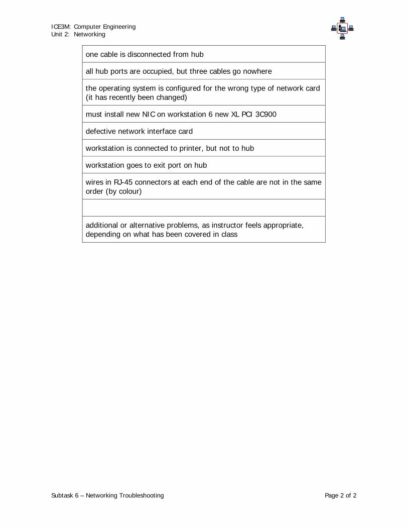
ICE3M: Computer Engineering Unit 2: Networking
Subtask 6 – Networking Troubleshooting Page 2 of 2
one cable is disconnected from hub
all hub ports are occupied, but three cables go nowhere
the operating system is configured for the wrong type of network card (it has recently been changed)
must install new NIC on workstation 6 new XL PCI 3C900
defective network interface card
workstation is connected to printer, but not to hub
workstation goes to exit port on hub
wires in RJ-45 connectors at each end of the cable are not in the same order (by colour)
additional or alternative problems, as instructor feels appropriate, depending on what has been covered in class

ICE3M: Computer Engineering Unit 2: Networking
Subtask 6 – Networking Troubleshooting Page 1 of 2
Network Troubleshooting Exercise Students will do this exercise in pairs or in small groups, as assigned by the instructor. Visit as many of the workstations identified as having network problems as possible. For each workstation, try to determine what the problem(s) are, and what you could do to fix them. Make good notes of the symptoms, problems and possible solutions. Test your solutions if you have time, but you must leave the workstations as you found them, so that the next group has a proper chance! Group: ______________________________ Workstation: ______________________________ Problem(s): ____________________________________________________________ ____________________________________________________________ Solution(s): ____________________________________________________________ ____________________________________________________________ ____________________________________________________________ ____________________________________________________________ Workstation: ______________________________ Problem(s): ____________________________________________________________ ____________________________________________________________ Solution(s): ____________________________________________________________ ____________________________________________________________ ____________________________________________________________ ____________________________________________________________

ICE3M: Computer Engineering Unit 2: Networking
Subtask 6 – Networking Troubleshooting Page 2 of 2
Workstation: ______________________________ Problem(s): ____________________________________________________________ ____________________________________________________________ Solution(s): ____________________________________________________________ ____________________________________________________________ ____________________________________________________________ ____________________________________________________________ Workstation: ______________________________ Problem(s): ____________________________________________________________ ____________________________________________________________ Solution(s): ____________________________________________________________ ____________________________________________________________ ____________________________________________________________ ____________________________________________________________ Workstation: ______________________________ Problem(s): ____________________________________________________________ ____________________________________________________________ Solution(s): ____________________________________________________________ ____________________________________________________________ ____________________________________________________________ ____________________________________________________________

Networking Subtask 7Culminating Task (Summative)
Network components, Types and Topologies A Unit for Grade 11 ~ 3.75 hours
ExpectationsTFV.02 A · describe the relationship among computer
hardware, networks, and operating systems;SPV.04 A · use network services to facilitate intranetworking
among workstations.TF2.03 A – identify differences between stand-alone and
network hardware;TF2.04 A – describe similarities and differences between
network and desktop operating systems.SPV.03 A · properly install and configure key computer
hardware and software components;SP2.03 A – properly install and configure key software and
hardware components and peripherals;SP2.04 A – properly install and configure a workstation
operating system, including a network connection;SP2.07 A – properly implement standard network protocols
for file transfer.IC1.03 A – describe issues that arise from the growing use of
networked systems (e.g., complexity, compatibility,security);
DescriptionAs a culminating task for this unit, students will create a simple network consisting of two computers. Studentswill install network adaptor cards into working computer systems, build the required networking cables, andphysically connect the two computers in a star network topology using a hub. Students will then configure theoperating system to connect the two computers in a peer-to-peer network, with file and print sharing, andtroubleshoot any problems that arise. Students will maintain a log during the construction of the network, andwill submit this with a report detailing the construction, including photographs and diagrams.
GroupingsStudents Working Individually
Teaching / Learning StrategiesProblem SolvingTechnical Design Process
AssessmentAn additional assessment strategy will be awritten project report.
Students will maintain a log during theconstruction of the network, and will submitthis with a report detailing the construction,including photographs and diagrams. Thefinal report will be submitted with aself-evaluation, which will be markedaccording to a separate rubric.
Assessment StrategiesPerformance TaskLearning LogSelf Assessment
Assessment Recording DevicesRubric
Resources
Teaching / LearningFor this culminating task, students will work individually to construct a working network. They will use problemsolving and technical design processes to plan and design their network, and to implement their plan. Problemsolving will also be used to identify and resolve any problems arising during the troubleshooting phase of theimplementation, as required.
AdaptationsSee the Unit Overview under Considerations for general accommodations.
Written using the Ontario Curriculum Unit Planner 3.0.1R PLNR2002R Official Version, Runtime Open Printed on 10 Mar, 2005 at 5:50:26 PM PageC-__

Networking Subtask 7Culminating Task (Summative)
Network components, Types and Topologies A Unit for Grade 11 ~ 3.75 hours
Culminating Task Rubric culminating task rubric.doc
Culminating Task culminating task.doc
Notes to TeacherThis is the culminating task of the unit, and is summative in nature. Students construct a simple network,installing and configuring components and troubleshooting any problems. They then prepare a written report,including photographs and diagrams, and submit this with a written log of the task.
Teacher Reflections
Written using the Ontario Curriculum Unit Planner 3.0.1R PLNR2002R Official Version, Runtime Open Printed on 10 Mar, 2005 at 5:50:26 PM PageC-__

ICE3M: Computer Engineering Unit 2: Networking
Subtask 7 – Culminating Task Page 1 of 1
Culminating Networking Task As the culminating task for this unit, you are to create a simple network of two computers and one hub. You are given the following equipment and materials:
2 x working computer systems, with Windows 98
1 x 100baseT 100 Mbps hub
2 x 3-metre lengths of unshielded twisted pair cable
6 x RJ-45 connectors
2 x 100 Mbps network interface cards, with drivers
1 x printer
1 x cable stripping/crimping tool
1 x cable tester
1 x digital camera Your tasks are:
1. Construct two working UTP cables.
2. Install the two network interface cards and drivers.
3. Connect the two computers into a star network, using the hub.
4. Configure the two computers in a peer-to-peer network.
5. Set up the network to share file folders and the printer. Note: You must keep a log during this culminating task, including any troubleshooting that you find necessary. This log will be part of the evaluation of this task. You should also be taking pictures at various stages, to include in your report. When you have finished the above tasks, your instructor will evaluate your performance and your log. You will then create a report of the process, including any pictures you have taken and any diagrams you have made. This report is to be submitted within two days of completing the performance task. The evaluation rubric is attached.

ICE3M: Computer Engineering Unit 2: Networking
Subtask 7 – Culminating Task Page 1 of 3
Teacher: Mr. David Keffer School: Date: Course: ICE3B: Computer Engineering
Grade 11, Workplace Culminating Task Rubric
Constructing and Configuring a Network
Students will create a simple network consisting of two computers. Students will install network adaptor cards into working computer systems, build the required networking cables, and physically connect the two computers in a star network
topology using a hub. Students will then configure the operating system to connect the two computers in a peer-to-peer network, with file and print sharing. Students
will maintain a log during the construction of the network, and will submit this with a report detailing the construction, including photographs and diagrams.
Expectations: TFV.02, TF2.03, TF2.04, SPV.03, SPV.04, SP2.03, SP2.04, SP2.07, IC1.03
Criteria: Level 1 Level 2 Level 3 Level 4
Knowledge
describe networking concepts, providing details
description of networking concepts provides limited details (1 mark)
description of networking concepts provides some details (2 marks)
description of networking concepts provides considerable details (3 marks)
description of networking concepts provides thorough details (4 marks)
describe networking concepts, providing examples
description of networking concepts makes limited reference to examples (1 mark)
description of networking concepts makes some reference to examples (2 marks)
description of networking concepts makes considerable reference to examples (3 marks)
description of networking concepts makes thorough reference to examples (4 marks)
identify networking hardware components (eg. network cards, hub, cables, tools)
identifies networking hardware components with limited success (1 mark)
identifies networking hardware components with some success (2 marks)
identifies networking hardware components with considerable success (3 marks)
identifies networking hardware components with excellent success (4 marks)
identify proper layout for star network topology
identifies proper layout for star network topology with some limited success (1 mark)
identifies proper layout for star network topology with some success (2 marks)
identifies proper layout for star network topology with considerable success (3 marks)
identifies proper layout for star network topology with excellent success (4 marks)

ICE3M: Computer Engineering Unit 2: Networking
Subtask 7 – Culminating Task Page 2 of 3
Thinking describe networking concepts in an organized manner
description of networking concepts demonstrates limited organization (1 mark)
description of networking concepts demonstrates some organization (2 marks)
description of networking concepts demonstrates considerable organization (3 marks)
description of networking concepts demonstrates a high level of organization (4 marks)
explain proper procedure for handling electronic networking components
gives a limited explanation of the proper procedure for handling electronic networking components (1 mark)
gives some explanation of the proper procedure for handling electronic networking components (2 marks)
gives a good explanation of the proper procedure for handling electronic networking components (3 marks)
gives a thorough explanation of the proper procedure for handling electronic networking components (4 marks)
design an appropriate star topology network
design an appropriate star topology network with limited accuracy (1 mark)
design an appropriate star topology network with some accuracy (2 marks)
design an appropriate star topology network with considerable accuracy (3 marks)
design an appropriate star topology network with a high level of accuracy (4 marks)
Communication
describe networking concepts clearly (eg. in report)
describes networking concepts with limited clarity (1 mark)
describes networking concepts with some clarity (2 marks)
describes networking concepts with considerable clarity (3 marks)
describes networking concepts with a high level of clarity (4 marks)
communicate information clearly and effectively (eg. in log and report)
communicates information with limited clarity and effectiveness (1 mark)
communicates information with some clarity and effectiveness (2 marks)
communicates information with considerable clarity and effectiveness (3 marks)
communicates information with a high level of clarity and effectiveness (4 marks)
communicate information accurately (eg. in log and report)
communicates information with limited accuracy (1 mark)
communicates information with some accuracy (2 marks)
communicates information with considerable accuracy (3 marks)
communicates information with a high level of accuracy (4 marks)
communicate information using an appropriate format (eg. use of photographs and diagrams in log and report)
demonstrates limited ability to communicate information using an appropriate format (1 mark)
demonstrates some ability to communicate information using an appropriate format (2 marks)
demonstrates considerable ability to communicate information using an appropriate format (3 marks)
demonstrates a high level of ability to communicate information using an appropriate format (4 marks)
Application
handle computer hardware appropriately (eg. with regard to proper and safe care of equipment)
rarely handles computer hardware appropriately (1 mark)
sometimes handles computer hardware appropriately (2 marks)
often handles computer hardware appropriately (3 marks)
always or almost always handles computer hardware appropriately (4 marks)
use appropriate strategies to keep safe and healthy in a computer environment (eg. with regard to personal safety)
rarely uses appropriate strategies to keep safe and healthy in a computer environment (1 mark)
sometimes uses appropriate strategies to keep safe and healthy in a computer environment (2 marks)
often uses appropriate strategies to keep safe and healthy in a computer environment (3 marks)
always or almost always uses appropriate strategies to keep safe and healthy in a computer environment (4 marks)

ICE3M: Computer Engineering Unit 2: Networking
Subtask 7 – Culminating Task Page 3 of 3
properly install and configures network cards and device drivers
properly installs and configures network cards and device drivers with limited success (1 mark)
properly installs and configures network cards and device drivers with some success (2 marks)
properly installs and configures network cards and device drivers with considerable success (3 marks)
properly installs and configures network cards and device drivers with excellent success (4 marks)
properly construct network cables (2)
properly constructs network cables (2) with limited success (1 mark)
properly constructs network cables (2) with some success (2 marks)
properly constructs network cables (2) with considerable success (3 marks)
properly constructs network cables (2) with excellent success (4 marks)
properly connect computers and other network components in peer-to-peer network
properly connect computers and other network components in peer-to-peer network with limited success (1 mark)
properly connect computers and other network components in peer-to-peer network with some success (2 marks)
properly connect computers and other network components in peer-to-peer network with considerable success (3 marks)
properly connect computers and other network components in peer-to-peer network with excellent success (4 marks)
properly configure operating system software for networking
properly configures operating system software for networking with limited effectiveness (1 mark)
properly configures operating system software for networking with some effectiveness (2 marks)
properly configures operating system software for networking with considerable effectiveness (3 marks)
properly configures operating system software for networking with excellent effectiveness (4 marks)
properly test and demonstrate working network (eg. demonstrate file and print sharing)
properly test and demonstrate working network with limited success (1 mark)
properly test and demonstrate working network with some success (2 marks)
properly test and demonstrate working network with considerable success (3 marks)
properly test and demonstrate working network with excellent success (4 marks)
Totals: Knowledge: _____ /16 = _____ /16 Thinking: _____ /12 = _____ /12 Communication: _____ /16 = _____ /16 Application: _____ /28 (x2) = _____ /56 Total Mark: = _____ /100 = _____ % Parent Name (please print): ______________________________ Signature: ______________________________ Date: _______________ Please sign and return this complete form to Mr. Keffer. Thank you.
Mr. D. Keffer


![[Maksimenkova_Neznanov] Peer Assessment to Programmers & Peer Assessment System for Complex Artifacts](https://img.pdfslide.net/doc/110x75/587ac6251a28ab760f8b4577/maksimenkovaneznanov-peer-assessment-to-programmers-peer-assessment-system.jpg)