Embed Size (px)
Citation preview

EARTHQUAKE ENGINEERING AND STRUCTURAL DYNAMICS
Earthquake Engng. Struct. Dyn. 27, 1225—1245 (1998)
NEURAL NETWORKS FOR STRUCTURAL CONTROL OFA BENCHMARK PROBLEM, ACTIVE TENDON SYSTEM
KHALDOON BANI-HANIs AND JAMSHID GHABOUSSI*,t
Department of Civil Engineering, University of Illinois at Urbana-Champaign, Urbana, IL 61801, U.S.A.
SUMMARY
Methodology for active structural control using neural networks has been proposed by Ghaboussi and his co-workers1—8
in the past several years. The control algorithm in the mathematically formulated methods is replaced by a neuralnetwork controller (neuro-controller). Neuro-controllers have been developed and applied in linear and nonlinearstructural control. Neuro-controllers are trained with the aid of the emulator neural networks. The emulator neuralnetwork is trained to learn the transfer function between the actuator signal and the sensor reading and it uses that pastvalues of these quantities to predict the future values of the sensor readings. In this paper, we apply the previouslydeveloped neuro-control method in the benchmark problem of the active tendon system. The emulator neural network isdeveloped and trained using the evaluation model given in the benchmark problem which is considered to be the truerepresentation of the active tendon system. However, a reduced-order model has been developed and used, along with theemulator neural network, to train the neuro-controller. The evaluation model represents the three story steel framestructure, including the actuator dynamics. The absolute acceleration of the first floor and the actuator pistondisplacement are used as feedback. Three neuro-controllers, with different control criteria, have been developed and theirperformances have been evaluated with the prescribed performances indexes. The robustness of the neuro-controllers inthe presence of some severe uncertainties, has also been evaluated. ( 1998 John Wiley & Sons, Ltd.
KEY WORDS: active control; neural networks; structures; earthquake engineering; dynamics
INTRODUCTION
Extensive research in the active control of civil engineering structures over the past few years have resulted invarious algorithms, strategies and devices.9 Most of these control methods require an accurate identificationtechnique that can construct a precise mathematical model for the dynamics of the controlled system.Therefore, these methods can be called model-based control methods or mathematically formulatedmethods. On the other hand, control methods which acquire their capabilities through learning andadaptation, such as neuro-controllers and neuro-fuzzy-controllers, can be considered non-model-basedmethods or intelligent methods or adaptive methods. In spite of the remarkable developments in the field ofstructural control, no direct comparative study have been made between various proposed control methods.In this paper the neural network-based structural control method is evaluated, as part of a comparative studybetween the structural control methods initiated by the Structural Control Committee of ASCE.
Structural control methods, utilizing the learning capabilities of neural network have been developed byGhaboussi and his co-workers. A neuro-control method based on the inverse transfer function wasdeveloped and applied in an experimental study of the actuator dynamics and delay compensation.7A neuro-control method which utilizes an emulator neural network (neuro-identifier) in its training, was
* Correspondence to: Jamshid Ghaboussi, Department of Civil Engineering, University of Illinois at Urbana-Champaign, Urbana,IL 61801, U.S.A.
s Research Assistantt Professor of Civil Engineering
CCC 0098—8847/98/111225—21$17)50 Received 13 May 1997( 1998 John Wiley & Sons, Ltd. Revised 2 December 1997
developed and applied in linear and non-linear structural control.1—6 A similar method has been proposed byChen et al.10 Unlike the conventional control algorithms where the control task is explicitly formulated, inthe neural network-based structural control methods the neuro-controller learns the control task. Theneuro-controller acquires the knowledge of structural control from a set of training cases and stores thatknowledge in its connection weights. One of the attractions of neural networks is that they are capable oflearning complex non-linear relationships. It is for this reason that neural network-based control methodsare equally effective in non-linear as well as in linear control problems.
In this study, an emulator neural network and three neuro-controllers, based on different control criteria,were developed and trained using the evaluation model described in the SIMU-LINK11 program providedfor the benchmark problem. The effectiveness of the trained neuro-controllers have been evaluated throughtwo sets of criteria; the root mean squares (rms) of the responses of the structure when it is subjected toexcitation of a stationary random process with a spectral density function defined by the Kanai—Tajimispectrum; and, the peak responses when the structure is subjected to the compressed 1940 E1 Centro NSearthquake record and the compressed 1968 Hachinohe NS earthquake record. Finally, a study of therobustness of the neuro-controllers has been conducted and reported.
NEURO-CONTROL METHOD
Neuro-controller is a neural network which replaces the control algorithm in the mathematically formulatedcontrol methods. A typical neuro-controller is shown in Figure 1. Neuro-controllers can either be imple-mented in hardware or simulated in software, in the latter case, the neuro-controller is in the form ofa software, residing in the control computer. Similar to the other control algorithms, the neuro-controllerreceives the feedback signal from the sensor (or sensors) at its input layer and issues an appropriate signal tothe actuator from its output layer. In the software implementation of the neuro-controller, the sensor data isreceived at discrete-time intervals, referred to as the sampling periods, ¹
4. The output of the neuro-controller
is also sent to the actuator at the same discrete sampling periods. In addition to the latest sensor reading, the inputto the neuro-controller also consists of the history of both the sensor readings and the actuator ram displacement,at several previous sampling periods. In the present implementation of the neuro-controller, we have used twosensors and one actuator. The sensors consist of an accelerometer measuring the horizontal absolute accelerationat the first floor, x
!1, and a rigidly mounted LVDT measuring the actuator piston displacement, x
1.
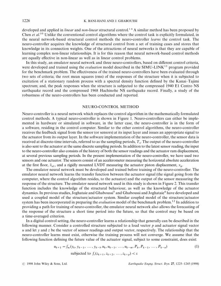
The emulator neural network must be developed and trained before training of the neuro-controller. Theemulator neural network learns the transfer function between the actuator signal (the signal going from thecomputer, where the control algorithm resides, to the actuator) and the output of the sensor measuring theresponse of the structure. The emulator neural network used in this study is shown in Figure 2. This transferfunction includes the knowledge of the structural behaviour, as well as the knowledge of the actuatordynamics. In previous studies, Joghataie and Ghaboussi5 and Ghaboussi and Joghataie4 have developed andused a coupled model of the structure/actuator system. Similar coupled model of the structure/actuatorsystem has been incorporated in preparing the evaluation model of the benchmark problem.12 In addition toproviding a path for training of neuro-controller, the emulator neural network also allows the forecasting ofthe response of the structure a short time period into the future, so that the control may be based ona time-averaged criterion.
In a digital control setting, the neuro-controller learns a relationship that generally can be described in thefollowing manner. Consider a controlled structure subjected to a load vector p and actuator signal vectoru and let y and z be the vector of sensor readings and output vector, respectively. The relationship that theneuro-controller learns must exist, otherwise the training process will not converge. We assume that thefollowing function defining the future value of the actuator signal, subject to some constraint, does exist:
uk`1
"fnc
(yk, y
k~1, 2, y
k~l, u
k, u
k~1, 2, u
k~m, P
k, P
k~1, 2, P
k~n) (1)
subjected to fc(z
k`1, z
k`2, 2 , z
k`p)(e
1226 K. BANI-HANI AND J. GHABOUSSI
( 1998 John Wiley & Sons, Ltd. Earthquake Engng. Struct. Dyn. 27, 1225—1245 (1998)

Figure 1. The neuro-controller and its SIMULINK model
Note that the arguments of the function include a portion of the past history of the sensor readings, actuatorsignal and loading. The constraint equation is a function of the future values of the output vector. The mainparameters of this function are the extent of the past digital values of the arguments l, m, n and p. Sucha relationship would always exist for sufficiently large values of these parameters. These parameters are ingeneral related to the degree of non-linearity of underlying process represented by the function. Currently,there are no rigorous methods of determining these parameters. It is important to note that the function inequation (1), which must be learned by the neuro-controller also includes the effects of actuator dynamic,actuator saturation, time delays and the sampling period. It is therefore, a highly non-linear function. Indesigning neuro-controllers, the values of the parameters l, m, n and p are determined by trial and error.
ACTIVE TENDON SYSTEM 1227
( 1998 John Wiley & Sons, Ltd. Earthquake Engng. Struct. Dyn. 27, 1225—1245 (1998)
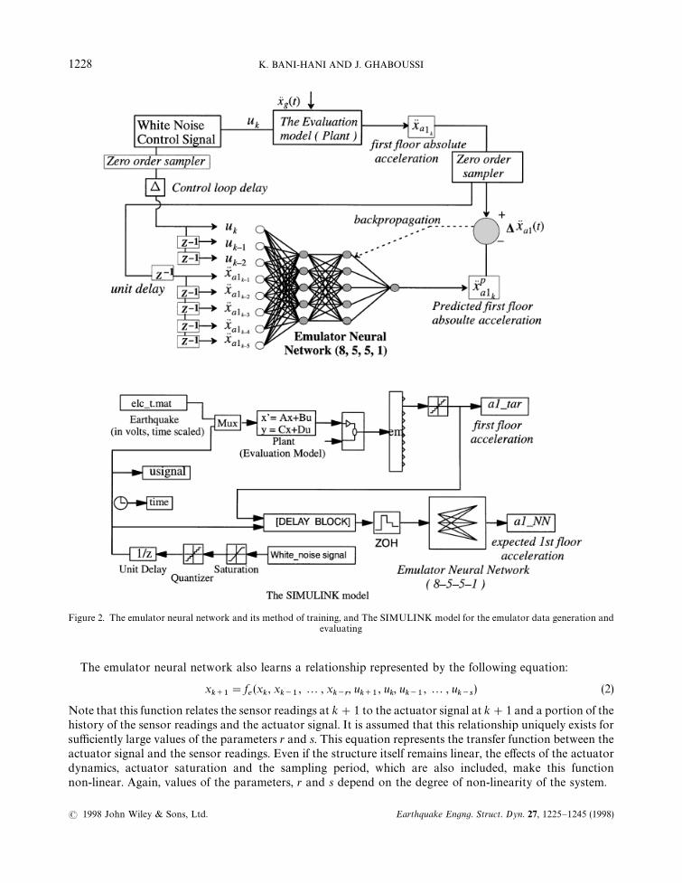
Figure 2. The emulator neural network and its method of training, and The SIMULINK model for the emulator data generation andevaluating
The emulator neural network also learns a relationship represented by the following equation:
xk`1
"fe(x
k, x
k~1, 2 , x
k~r, u
k`1, u
k, u
k~1, 2 , u
k~s) (2)
Note that this function relates the sensor readings at k#1 to the actuator signal at k#1 and a portion of thehistory of the sensor readings and the actuator signal. It is assumed that this relationship uniquely exists forsufficiently large values of the parameters r and s. This equation represents the transfer function between theactuator signal and the sensor readings. Even if the structure itself remains linear, the effects of the actuatordynamics, actuator saturation and the sampling period, which are also included, make this functionnon-linear. Again, values of the parameters, r and s depend on the degree of non-linearity of the system.
1228 K. BANI-HANI AND J. GHABOUSSI
( 1998 John Wiley & Sons, Ltd. Earthquake Engng. Struct. Dyn. 27, 1225—1245 (1998)
The neuro-controller and the emulator neural network learn the relationships represented by equations (1)and (2). However, neural network reprehension is not exactly the same as the functions they learn. For thisreason we use a different symbol to represent the trained neural networks:
uk`1
"NN/#
(yk, y
k~1, 2, y
k~l,u
k, u
k~1, 2 , u
k~m, p
k, p
k~1, 2 , p
k~n) (3)
xk`1
"NN%(x
k, x
k~1, 2 , x
k~r, u
k`1, u
k, u
k~1, 2, u
k~s) (4)
Whereas, the mathematical functions are exact and universally true, the neural networks approximate theseunderlying functions over a limited range of interest. The uniqueness requirements for the neural networksare far more relaxed than for mathematical functions. For the neural network training to be successful, theunderlying function must exist but need not be strictly unique. Moreover, even if the underlying functionuniquely exists, the neural network architecture is not unique; more than one neural network can learn thesame underlying function to within a given degree of accuracy over a limited range.
In training of any neural network, a set of training cases, consisting of input/output pairs, are needed. Thetraining cases for the emulator neural network are generated either through numerical simulation (theevaluation model and the SIMULINK11 program in our case) or in an experimental setting by sendingsignals to the actuator and recording the sensor outputs. The same procedure cannot be used for generatingtraining cases for the neuro-controller, since the correct values of the output are not known. The purpose ofthe emulator neural network is to provide a path for back-propagation of the errors in training of theneuro-controller. The procedure for training of the neuro-controller with the aid of the emulator neuralnetwork is schematically shown in Figure 3.
The neural network training method used in this study, as well as the previous studies by Ghaboussi andhis co-workers, is an adaptive architecture determination method, which was originally developed in199013—15 and, has since been modified and improved.16 This method, combines the ‘Quickprop’ trainingalgorithm proposed by Fahlman17 and the dynamic node generation method proposed by Ash.18 Theessentials of the training method used in this study has been described in Joghataie, Ghaboussi and Wu.16The training process starts with a small part of the training cases and small number of nodes in the hiddenlayers (not less than two nodes). As the training proceeds, more training cases are added and the rate oflearning is monitored. When the rate of learning falls below a certain value, which indicates that the networkis approaching its capacity, one new node is added to each hidden layer. The training is continued for a timewith the old connection weights frozen, so that the new connection weights can learn part of the knowledgewhich was not learned by the old connection weights. Subsequently, the old connection weights are unfrozenand the training continues with all the connection weights. This process is continued until all the neuralnetwork learn all the training cases.
The adaptive training method which was briefly described in the previous paragraph, obviously has manyparameters, such as: how to divide the training cases into smaller packets; when to add a new packet oftraining cases; why add one node at a time to the hidden layers instead of two or more nodes; how longshould the old connection weight be frozen, etc. As in many other aspects of the neural networks, there are nounique answers to these questions. Our experience has shown that the overall training of the neural networksand the performance of the trained networks are, to a great extent, insensitive to these parameters. We havedeveloped a set a empirical rules which work for these class of problems. Some of these rules have beendescribed in Reference 16. However, the relative effectiveness of these rules may be problem dependent.
BENCHMARK PROBLEM, ACTIVE TENDON SYSTEM
The system considered in this study is a 1 : 4 scale model of a three-storey building considered in Chung etal.,19 that has become a standard model for structural control problems. Several experiments have beenperformed on this model at NCEER at SUNY, Buffalo. A similar system has been built in the Department ofCivil Engineering at the University of Illinois at Urbana Champaign by Ghaboussi and his co-workers, for
ACTIVE TENDON SYSTEM 1229
( 1998 John Wiley & Sons, Ltd. Earthquake Engng. Struct. Dyn. 27, 1225—1245 (1998)
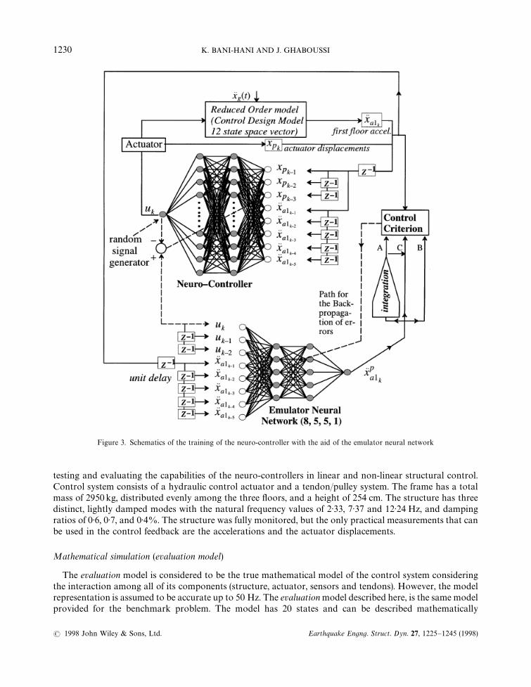
Figure 3. Schematics of the training of the neuro-controller with the aid of the emulator neural network
testing and evaluating the capabilities of the neuro-controllers in linear and non-linear structural control.Control system consists of a hydraulic control actuator and a tendon/pulley system. The frame has a totalmass of 2950 kg, distributed evenly among the three floors, and a height of 254 cm. The structure has threedistinct, lightly damped modes with the natural frequency values of 2)33, 7)37 and 12)24 Hz, and dampingratios of 0)6, 0)7, and 0)4%. The structure was fully monitored, but the only practical measurements that canbe used in the control feedback are the accelerations and the actuator displacements.
Mathematical simulation (evaluation model)
The evaluation model is considered to be the true mathematical model of the control system consideringthe interaction among all of its components (structure, actuator, sensors and tendons). However, the modelrepresentation is assumed to be accurate up to 50 Hz. The evaluation model described here, is the same modelprovided for the benchmark problem. The model has 20 states and can be described mathematically
1230 K. BANI-HANI AND J. GHABOUSSI
( 1998 John Wiley & Sons, Ltd. Earthquake Engng. Struct. Dyn. 27, 1225—1245 (1998)
as follows:
x5 (t)"Ax (t)#Bu (t)#Ex'
(5)
y (t)"Cyx (t)#D
yu (t)#F
yx'#v(t) (6)
z (t)"Czx (t)#D
zu (t)#F
zx'
(7)
where, x(t) is the 20-dimensional state-space vector, u(t) the single actuator signal, x'the horizontal ground
acceleration, v(t) the measurement noise vector, y(t)"[x1, x
!1, x
!2, x
!3, f, x
']T is six-dimensional states
observation vector (sensors readings), and z(t)"[x1, x
2, x
3, x
1, xR
1, xR
2, xR
3, xR
1, x
!1, x
!2, x
!3, f ]T is the output
vector of the system that can be regulated (12 states), and A, B, E, Cy, D
y, F
y, C
z, D
zand F
zare the
appropriate matrices. This evaluation model has been used in training the emulator and in the evaluation ofthe neuro-controllers. However, the neuro-controller has been designed using a reduced order model, that hasbeen developed with a 12-dimensional state-space vector (xc, x
r)12) as required by the benchmark problem
specifications, although neuro-controllers can be easily trained on the evaluation model itself and they do notrequire a reduced-order model.
The emulator neural network has some advantages over the classical identification methods; it can betrained with the measured data during an experiment or from the recorded time histories, without requiringany mathematical formulation. As a result, we can use the evaluation model with its 20-dimensionalstate-space vector to train the emulator neural network, assuming that the evaluation model represents theactual structure. The emulator neural network can be described in the following form:
xa1k"NN
%(xa1
k~1, 2 , xa1
k~5, u
k~2, u
k~1, u
k) (8)
where xa1kand u
kare the first floor absolute acceleration and the control signal at t"k¹
4. Obviously, the
emulator can predict the response of the structure from the history of the responses, and the current signaland a portion of the past history of the signal. On the other hand, the neuro-controller, is trained using thereduced-order model and the emulator neural network. The 12 state reduced-order model has been developedusing the balanced model truncation technique with the tools found in the MATLAB20 control toolbox.Although the neuro-controller is trained on the reduced-order model, when the trained neuro-controller isused it receives its feedback from the actual structure (evaluation model). The neuro-controller can be writtenin the following form:
uk"NN
/#(xa1
k~1, 2 , xa1
k~5, xp
k~1, xp
k~2, xp
k~3) (9)
where xa1k, xp
kare the first floor absolute acceleration and the actuator displacement at t"k¹
4.
The simulation of the system dynamics was done using the SIMULINK11 software with the followingsimulation parameters: sampling time period ¹
4"0)001 sec, control loop time delay q"200 lsec, integra-
tion time step dt"0)0001 sec. The A/D, D/A converters on the digital control have a 12 bit precision anda span of $3V, which gives a resolution of +1)5 mV. These values have been stated explicitly in thebenchmark problem.
Performance indexes, and the evaluations criteria
Some common evaluation criteria have been selected, to be used in the benchmark problem, so thecomparison can be made. These criteria are divided into two categories.
Performance criteria based on the rms of the responses
The first set of performance criteria, are the values of the root mean squares (rms) of the structuralresponses when the system is subjected to a stationary random process with the spectral density functiondefined by the Kanai—Tajimi spectrum.
Sx'x'(w)"
So(4f2
'w2
'w2#w4
')
(w2!w2')2#4f2
'w2
'w2
(10)
ACTIVE TENDON SYSTEM 1231
( 1998 John Wiley & Sons, Ltd. Earthquake Engng. Struct. Dyn. 27, 1225—1245 (1998)
where it is assumed that w'and f
'vary within the ranges of: 8rad/s)w
')50 rad/sec and 0)3)f
')0)75.
The spectral intensity S0
is chosen such that the rms of the ground motion is constant and has a value of0)034 g. The following performance indexes will to be evaluated and reported:
J1"max
w',f
'G
pd1
px30
,pd
2
px30
,pd
3
px30H (11)
J1"max
w',f
'G
px!1
px!30
,px
!2
px!30
,px
!3
px!30H (12)
J3"max
w',f
'G
px1
px30H (13)
J4"max
w',f
'G
pxR1
pxR30H (14)
J5"max
w',f
'G
pf
¼H (15)
where pd*is the rms inter-storey drift value for the ith floor, px
!*the rms value for the absolute acceleration of
the ith floor, px1the rms value for the actuator displacements, pxR
1the rms value for the actuator velocity,
p&the rms value for the actuator force, and ¼ the total structure weight ("289 kN). The maximum rms
displacement for the third floor of the uncontrolled case were found to be px30"2)34 cm, the maximum
uncontrolled third floor velocity pxR30"33)3 cm/sec, and the maximum uncontrolled third floor absolute
acceleration px!30"0)485 g. These values occur when w
'"14)5 rad/s and f
'"0)3. Three other hard con-
straints were imposed for the neuro-controller: the rms of the control signal pu)1)0V; the rms of the control
force p&)4)0kN; and, the rms of the actuator displacement px
1)1)0 cm.
Performance criteria based on the peak responses
The second set of performance criteria are based on the peak responses of the controlled system, when thesystem is subjected to two compressed earthquake records; the 1940 E1 Centro NS record and the 1968Hachinohe NS record. The following performance indexes will be evaluated and reported:
J6" max
H!#)*/0)%E- C%/530
Amax(t)G
Dd1D
x30
,Dd
2D
x30
,Dd
3D
x30HB (16)
J7" max
H!#)*/0)%E- C%/530
Amax(t)GDx
!1D
x!30
,Dx
!2D
x!30
,Dx
!3D
x!30HB (17)
J8" max
H!#)*/0)%E- C%/530
Amax(t)G
Dx1D
x30HB (18)
J9" max
H!#)*/0)%E- C%/530
Amax(t)G
DxR1D
xR30HB (19)
J10" max
H!#)*/0)%E- C%/530
Amax(t)GD f D¼HB (20)
where d*is the inter-storey drift for the ith floor, x
!*is absolute acceleration of the ith floor, x
1is the actuator
piston displacement, xR1
is the actuator piston velocity, f is the actuator force, and ¼ is the total structure
1232 K. BANI-HANI AND J. GHABOUSSI
( 1998 John Wiley & Sons, Ltd. Earthquake Engng. Struct. Dyn. 27, 1225—1245 (1998)

weight ("289kN). For the uncontrolled system subjected to El Centro Earthquake we have the following:maximum displacement at the third floor x
30"6)45 cm; maximum velocity at the third xR
30"99)9 cm/sec;
and, maximum absolute acceleration at the third floor x30"1)57g. Similarly when the system is subjected to
Hachinohe earthquake record we have the following maxima: x3o"3)78 cm; xR
3o"56)1cm/sec; and,
x3o"0)778g. The hard constraints imposed on the neuro-controller were: the absolute maximum control
signal should not exceed 3)0V; the absolute maximum control force should not exceed 12)0 kN; and, theabsolute maximum actuator displacement should not exceed 3)0cm.
CONTROLLER DESIGN
The controller design using neural network methodology, has been developed and tested by Ghaboussi andhis co-workers in previous works, where two different methods were presented. A neuro-controller based onthe inverse transfer function was introduced and implemented experimentally by, Nikzad et al.7 In a secondmethod introduced by Ghaboussi and his co-workers,1,2,4 also used in this study, they used an emulatorneural network to train the neuro-controller. The neuro-controller design in this method, can be divided intotwo parts: first the emulator neural network is trained and evaluated; then, the neuro-controller is trained online with the aid of the emulator neural network. In this study one emulator neural network was developedand it was used to develop three different neuro-controllers, each with a different control criterion.
Emulator neural network (neuro-identifier)
The emulator is the first neural network to be trained. The emulator learns to predict the response of thestructure from the immediate past history of the structural response. The emulator is chosen to have twohidden layers. The input layer consists of eight nodes which represent: the absolute acceleration of the firstfloor of the frame at the last five past sampling periods; the current actuator signal and the actuator signals atthe past two sampling periods. The single output node represents the current absolute acceleration of the firstfloor. Figure 2 shows the architecture of the emulator neural network as well as its method of training. TheSIMULINK11 program, used in preparing the training data for the emulator, as well as in evaluating itsperformance, is also shown in Figure 2.
The emulator neural network can be considered a black box which represents the transfer functionbetween the actuator signal and the sensor readings. Clearly, this transfer function includes the structuralbehaviour. Therefore, it can be stated that the emulator learns some part of the structural behavior. However,the transfer function also includes the effects of the actuator dynamics and sampling period. The emulatorlearns to incorporate the effects of these important factors. The neuro-controller also learns to compensatefor the effects of the actuator dynamics, sampling period and the control loop time delays when it is trainedwith the aid of the emulator neural network.
Training of the emulator neural network has been accomplished by using the SIMULINK11 programprovided in the benchmark problem. Three analyses have been performed using the 20 state evaluation model:in the first analysis the system was subjected to the compressed 1940 El Centro earthquake NS record whilethe control force was turned off; in the second analysis the system was subjected to random white noiseactuator signal with no earthquake input; finally, in the third analysis the system was subjected toa combination of the earthquake ground motion and the white noise actuator signal. A 10)0 sec portion of theresults from three analyses was used to generate a total of 30000 training patterns for the emulator neuralnetwork. Figure 2 shows the SIMULINK11 model used in preparing the training data for the emulatorneural network. The same SIMULINK11 model was also used in evaluating the performance of the trainedemulator by adding the neural network block.
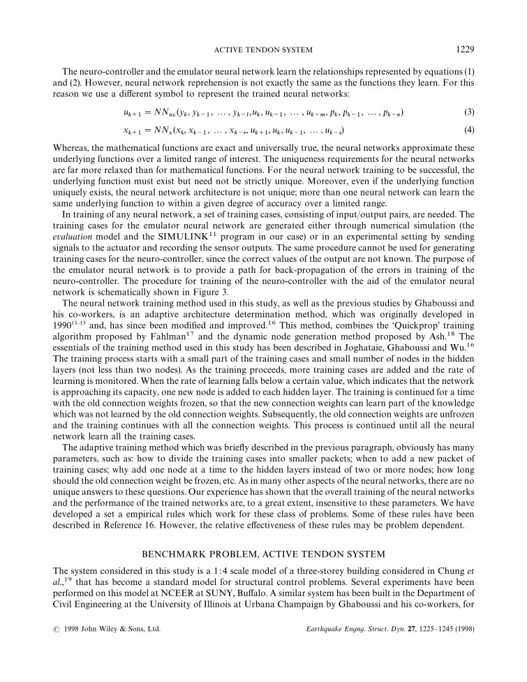
The performance of the emulator neural network was evaluated by comparing its response with the resultsof the analysis by the SIMULINK11 program using the 20 state evaluation model. This evaluation wasperformed for three different cases: (1) 100 sec period of white noise actuator command; (2) 100 per cent of
ACTIVE TENDON SYSTEM 1233
( 1998 John Wiley & Sons, Ltd. Earthquake Engng. Struct. Dyn. 27, 1225—1245 (1998)
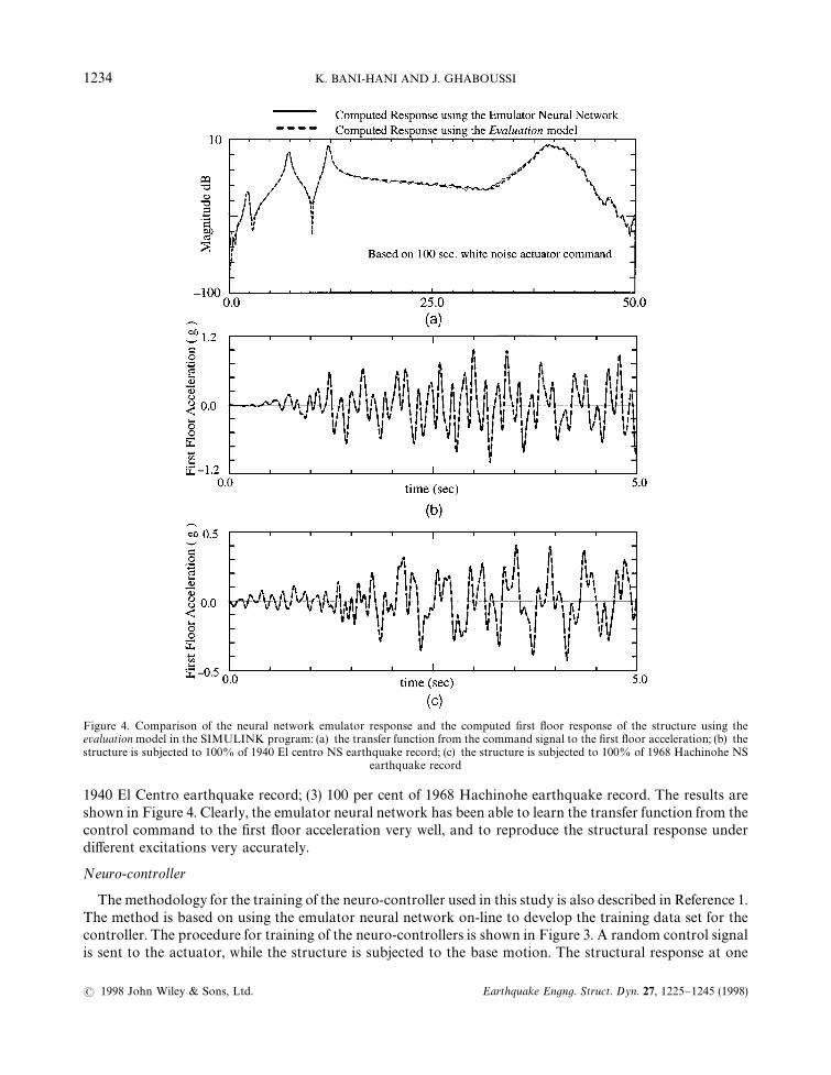
Figure 4. Comparison of the neural network emulator response and the computed first floor response of the structure using theevaluation model in the SIMULINK program: (a) the transfer function from the command signal to the first floor acceleration; (b) thestructure is subjected to 100% of 1940 El centro NS earthquake record; (c) the structure is subjected to 100% of 1968 Hachinohe NS
earthquake record
1940 El Centro earthquake record; (3) 100 per cent of 1968 Hachinohe earthquake record. The results areshown in Figure 4. Clearly, the emulator neural network has been able to learn the transfer function from thecontrol command to the first floor acceleration very well, and to reproduce the structural response underdifferent excitations very accurately.
Neuro-controller
The methodology for the training of the neuro-controller used in this study is also described in Reference 1.The method is based on using the emulator neural network on-line to develop the training data set for thecontroller. The procedure for training of the neuro-controllers is shown in Figure 3. A random control signalis sent to the actuator, while the structure is subjected to the base motion. The structural response at one
1234 K. BANI-HANI AND J. GHABOUSSI
( 1998 John Wiley & Sons, Ltd. Earthquake Engng. Struct. Dyn. 27, 1225—1245 (1998)
sampling period is collected and sent to the box labeled the control criterion. Simultaneously, the controlsignal is fed to the emulator neural network and its output is also sent to the box labeled the control criterion.In the control criterion box, the control error is determined and backpropagated through the emulatorneural network and through the neuro-controller. Only the connection weights of the neuro-controller aremodified. This process is repeated until the control criterion is satisfied and the control error is reduced tobelow a specified tolerance.
Mathematically, the process of backpropagating the control error through the emulator neural network,can be approached in different ways. Ghaboussi and Joghataie4 used an iterative loop for calculating thecontrol signal which satisfies the control criterion. They first computed the Jacobian, representing thesensitivity of the acceleration of the first floor with respect to the actuator signal. Then, they used the inverseof the Jacobian to calculate a correction for the actuator signal. When this process is applied iteratively, itleads to a control signal which will either satisfy the control criterion, or will cause the actuator saturation.Chen et al.,10 made use of the internal architecture of the emulator. They backpropagated the control errorthrough the emulator to determine the differential actuator signal error at the input of the emulator neuralnetwork. This scheme is repeated continuously, until the control criterion is satisfied for every samplingperiod or the actuator reaches saturation.
In this study, we use a method similar to the one used in Ghaboussi and Joghataie.4 It can be described asa search method. For each time step, we search for the actuator signal which satisfies the control criterion.This search is conducted by alternately varying the value of the actuator signal, u
j, j"1, 2 , n, between zero
and its limits u'
and umin
(!3 and 3V in our case) by increments of *uj. The total number of increments n is
determined by the following equation:
n"Cumax!u
.*/*u D (21)
When j"0 the case is called the uncontrolled reference case. The training set for the neuro-controller at eachtime step is obtained by satisfying the control criterion.
For each actuator signal increment, the emulator neural network is used to predict the structural responseat m future time steps. The actuator signal u
jis assumed to remain constant over the next m time steps while
the predicted structural response x1i!j
, i"1, 2 , m is determined using the emulator neural network. Thecontrol criterion is then based on a time-averaged value of the structural response. However, since thereliability of the emulator predicted structural response deteriorates with elapsed time, a weight function isassigned to each predicted response value. The weight function, called the importance function and it isa decreasing function of time.
Control criteria
Three neuro-controllers have been designed. The neuro-controller A has been designed with a controlcriterion based on the reduction of the predicted integrated relative displacements of the first floor.Neuro-controller B has been designed with a control criterion based on the reduction of the first flooraccelaration. Finally, neuro-controller C has been designed with a control criterion based on the simulta-neous reduction of the first floor relative displacements and first floor accelaration.
For neuro-controller A, the predicted absolute acceleration of the first floor is integrated twice todetermine the relative displacement, using Wilson’s # method.21 Wilson’s # method, uses the followingrelations between the accelerations, velocities and displacements at two successive time steps:
xi1j"xi~11
j#C
1*xi1
j#C
2xR i~11
j#C
3(xi~1a1
j!x
') (22)
xi1j"C
4*xi1
j#C
5xR i~11
j#C
6(xi~1a1
j!x
') (23)
xia1j"C
7*xi1
j#C
8xR i~11
j#C
9(xi~1a1
j!x
')#x
'(24)
where i indicates the predicted time step and j is the current actuator signal increment step and, C1!C
9are
functions of integration constant #*1)4 and the integration time step *t. By rearranging Equation
ACTIVE TENDON SYSTEM 1235
( 1998 John Wiley & Sons, Ltd. Earthquake Engng. Struct. Dyn. 27, 1225—1245 (1998)
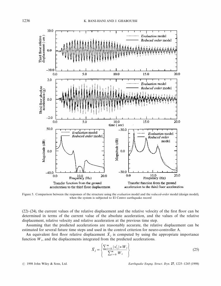
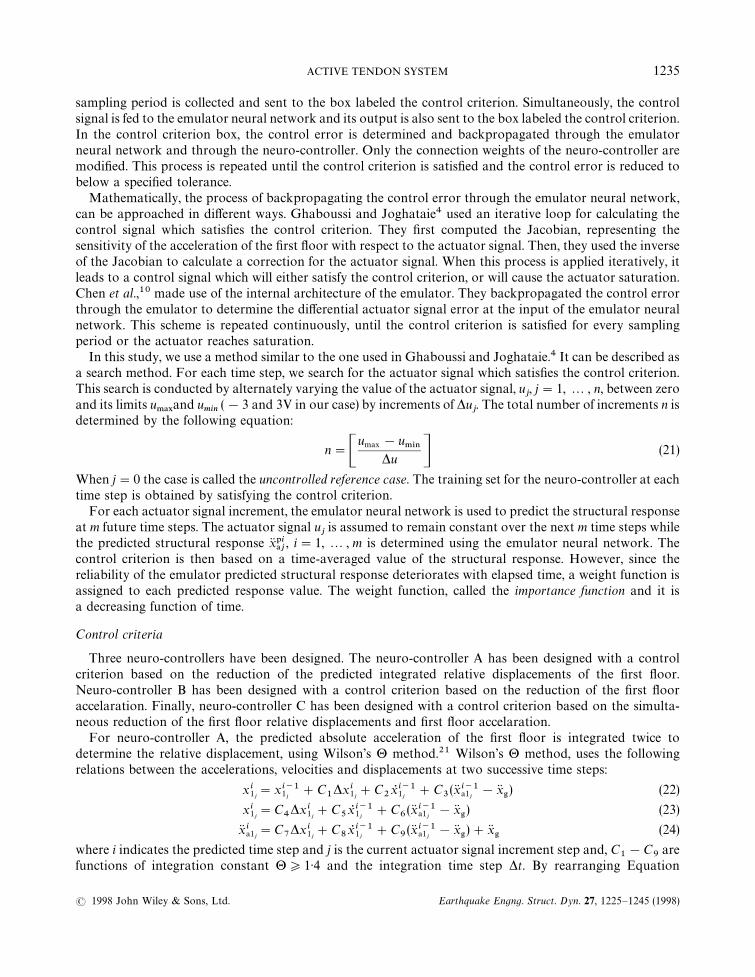
Figure 5. Comparison between the responses of the structure using the evaluation model and the reduced-order model (design model),when the system is subjected to El Centro earthquake record
(22)—(24), the current values of the relative displacement and the relative velocity of the first floor can bedetermined in terms of the current value of the absolute acceleration, and the values of the relativedisplacement, relative velocity and relative acceleration at the previous time step.
Assuming that the predicted accelerations are reasonably accurate, the relative displacement can beestimated for several future time steps and used in the control criterion for neuro-controller A.
An equivalent first floor relative displacement XMj
is computed by using the appropriate importancefunction ¼
i, and the displacements integrated from the predicted accelerations.
XMj"G
+mi/0
Dxi1jD*¼i
+mi/0
¼i H (25)
1236 K. BANI-HANI AND J. GHABOUSSI
( 1998 John Wiley & Sons, Ltd. Earthquake Engng. Struct. Dyn. 27, 1225—1245 (1998)
The average reference value for the uncontrolled case is XMR"XM
0*C$o
, for j"0 where C$o)1)0 is
a reduction factor. The control signal is chosen to satisfy the following control criterion: XMj)XM
Rand
XMj)e
$, where e
$is the control tolerance. If this criterion can not be met, then the control signal is chosen to
minimize XMj. The numerical values of the parameters used in the control criterion for training of the
neuro-controller A are: m"4, *u"0)001V, n"6000, e$"0)2 cm, C
$o"0)9 and the importance function is
defined by the following equation:
¼i"1)5!
(i!1)
m, i"1, 2 , m (26)
For the neuro-controller B, no integration was necessary since the control criterion is based on thereduction of the first floor absolute acceleration. An equivalent first floor acceleration X®M
jhas been estimated
with appropriate importance function ¼@i.
X®Mj"G
+mi/0
Dxi1ajD*¼i
+mi/0
¼i H (27)
The average reference value for the uncontrolled case is X®MR"X®M
0*C!0
, for j"0, and C!0)1)0. Similarly,
the control criterion is chosen such that the control signal satisfies the following: X®Mj)X®M
Rand X®M
j)e
!, where
e!is the control tolerance. If this criterion cannot be met, then the control signal is chosen to minimize X®M
j.
The numerical values of the parameters used in the control criterion for training of the neuro-controller
Table I. Evaluation Performance Indexes for the three designed controllers, The RMS perfor-mance and constraint values were evaluated at the nominal design point wg"14)5, zg"0)3
Controller A: (Reduction of the first floor relative disablement criterion)
RMS responses J1
J2
J3
J4
J5
pu
px1
p&
criteria (V) (cm) (kN)Broadband (K—T) 0)1871 0)3867 0)0396 0)0416 0)0090 0)7020 0)0927 2)6021Peak responses J
6J7
J8
J9
J10
u.!9
x1.!9
f.!9
criteria (V) (cm) (kN)El Centro 0)2743 0)7127 0)0674 0)2540 0)0379 3)9342 0)4345 10)960Hachinohe 0)3373 0)8460 0)0721 0)1014 0)0238 2)0996 0)2725 6)8805
Controller B: (Reduction of the first floor absolute acceleration criterion)
RMS responses J1
J2
J3
J4
J5
pu
px1
pf
criteria (V) (cm) (kN)Broadband (K—T) 0)1541 0)3302 0)0366 0)0346 0)0089 0)6791 0)0856 2)5944Peak responses J
6J7
J8
J9
J10
u.!9
x1.!9
f.!9
criteria (V) (cm) (kN)El Centro 0)2384 0)5148 0)0626 0)0804 0)0364 2)9616 0)4035 10)524Hachinohe 0)3103 0)8052 0)0622 0)0674 0)0279 1)8234 0)2352 8)0771
Controller C:
(Reduction of the first floor absolute acceleration and relative displacement criterion)
RMS responses J1
J2
J3
J4
J5
pu
px1
p&
criteria (V) (cm) (kN)Broadband (K—T) 0)1454 0)3121 0)0409 0)0360 0)0087 0)7642 0)0958 2)5207Peak responses J
6J7
J8
J9
J10
u.!9
x1.!9
f.!9
criteria (V) (cm) (kN)El Centro 0)2319 0)5112 0)0519 0)0569 0)0374 2)6844 0)3347 10)810Hachinohe 0)3011 0)7731 0)0708 0)0708 0)0273 2)1203 0)2677 7)8783
ACTIVE TENDON SYSTEM 1237
( 1998 John Wiley & Sons, Ltd. Earthquake Engng. Struct. Dyn. 27, 1225—1245 (1998)

Figure 6. Controlled and uncontrolled responses of the structure subjected to El Centro earthquake record
B are: m"4, *u"0)001V, n"6000, e!"0)25g, C
!0"0)95, and the importance function ¼
iis defined by
equation (26), same as in controller A.Finally, neuro-controller C, was trained with a control criterion based on the simultaneous reduction of
the first floor absolute acceleration and first floor relative displacement. Obviously, this criterion isa combinations of the control criteria for the neuro-controllers A and B. However, the control tolerancese$
and e!
were chosen in such a way that more emphasis is placed on the reduction of the first flooracceleration. An equivalent first floor acceleration X®M
jand an equivalent first floor relative displacement XM
j,
were computed using appropriate importance functions and equations (25) and (27).The numerical values of the parameters used in the control criterion for training of the neuro-controller
C are: m"4, *u"0)001 V, n"6000, e$"0)5 cm, C
$0"1)0, e
!"0)25g, C
!0"0)90, and ¼
ithe same as in
equation (26).
1238 K. BANI-HANI AND J. GHABOUSSI
( 1998 John Wiley & Sons, Ltd. Earthquake Engng. Struct. Dyn. 27, 1225—1245 (1998)

Figure 7. Controlled and uncontrolled response of the structure subjected to Hachinohe earthquake record
The three neuro-controllers A, B, and C were trained using a computer program simulating the methodo-logy shown in Figure 3. The design model for these controllers was a 12 states, reduced-order model, whichhas been developed from the evaluation model, using the balanced model truncation technique, available inthe MATLAB20 control toolbox. The reduced-order model can be described by the following state-spaceequations:
x5 r (t)"Ar (t)#Bru(t)#Er x'(28)
yr (t)"Cyrxr (t)#Dy
ru(t)#Fy
3x'#vr (t) (29)
where xr (t) is 12 state-space vector, and yr(t) is a state vector of the required measurements for the controllerdesign, yr (t)"[x
1, x
!1]T. Figure 5, shows a comparison between the responses of evaluation model and the
ACTIVE TENDON SYSTEM 1239
( 1998 John Wiley & Sons, Ltd. Earthquake Engng. Struct. Dyn. 27, 1225—1245 (1998)

Figure 8. Third floor frequency response for the controlled and uncontrolled structure when the structure is subjected to El Centroearthquake record, and Hachinohe earthquake record (neuro-controller)
reduced-order model in both time domain and frequency domain. It appears that the reduced-order model hasretained the essence of the original model without significant loss of generalization. In the simulatedcomputer program for the controllers design, both the reduced-order model and the emulator neural networkwere used to develop training cases for the three neuro-controllers. In training the neuro-controllers a 50 percent amplitude of the compressed 1940 El Centro earthquake record was used for a duration of 10 sec. Thisgenerated 10 000 training cases for each neuro-controller. It is interesting to note that, as mentioned earlier,adaptive architecture determination was used and three neuro-controller ended up with different number ofnode in their hidden layers, adaptively determined during the training process. Neuro-controller A ended thetraining process with 10 nodes in each of its two hidden layers; neuro-controller B with 7 nodes in each of itstwo hidden layers; and, neuro-controller C with 6 nodes in each of its two hidden layers. The final number of
1240 K. BANI-HANI AND J. GHABOUSSI
( 1998 John Wiley & Sons, Ltd. Earthquake Engng. Struct. Dyn. 27, 1225—1245 (1998)

Figure 9. Comparison between the transfer functions of the ground acceleration to third floor displacement and acceleration, for thecontrolled and uncontrolled structure. (neuro-controller C). (a) transfer functions from the ground acceleration to the third floor relativedisplacement; (b) transfer functions from the ground acceleration to the third floor absolute acceleration
nodes in the hidden layers in the adaptive architecture determination in somehow related to the degree ofdifficulty in learning of the information in the training data set.
NUMERICAL RESULTS
The three neuro-controllers have been evaluated in two stages. In the first stage, the performance of theneuro-controllers were evaluated using the evaluation criteria in equations (11)—(20), as prescribed in thebenchmark problem. In the second stage, we study the robustness of the trained neuro-controller byevaluating their performance under severe uncertainties.
The evaluation indexes are: the root mean squares of the controlled responses when the structure issubjected to a stationary random process with the PSD function defined by the Kanai—Tajimi spectrum; and,
ACTIVE TENDON SYSTEM 1241
( 1998 John Wiley & Sons, Ltd. Earthquake Engng. Struct. Dyn. 27, 1225—1245 (1998)

Table II. Comparisons between the peak responses of the controlled system and thecon-trolled system with some severe uncertainities.
Peak responses of the controlled (neuro-controller C) system subjected to El CentroEarthquake with different severe cases of uncertainities (assessments of robustness and
stability)
X1
X2
X3
X®!1
X®!2
X®!3
Case definition (cm) (cm) (cm) (g) (g) (g)
Uncontrolled system 2)0170 4)9737 6)5653 1)0809 1)2744 1)5631Evaluation model without 1)0920 2)3080 3)0125 0)6608 0)6267 0)7760any uncertainitiesCase 1: Time delay was 1)2125 2)7006 3)6537 0)7116 0)7244 0)9131
increased 10 timesCase 2: Uncertainities in 1)3643 3)3312 4)3643 0)7412 0)7584 0)9895
the model $ 15%Case 3: Uncertainities in 1)2147 2)4354 3)3061 0)9378 0)8232 0)8505
sensors readings of$0)3 volts.
the peak controlled responses when the structure is subjected to the compressed El Centro and Hachinoheearthquake records. The neuro-controllers A, B and C, which were trained on 50 per cent amplitude of ElCentro earthquake with three different control criteria, were able to control the structure when it is subjectedto a more severe earthquake (100 per cent amplitude of El Centro), as well as a different earthquake than theone they were trained on (Hachinohe). Table I summarizes the computed performance indexes for the threeneuro-controllers, for the three earthquake excitations. Figure 6 and 7 show the comparison between thecontrolled and the uncontrolled responses for the third floor absolute acceleration and the third floorabsolute acceleration and the third floor relative displacement, for neuro-controller C. Figure 8 shows thesame comparisons in the frequency domain.
Clearly, all three neuro-controllers appear effective in controlling the response of the structure. However,comparison of the J
1, J
2, J
6and J
7values reveal that neuro-controller C is somewhat more effective than
neuro-controllers A and B. It is recalled that neuro-controller C was trained with a control criterion whichincluded both the control criteria used in training neuro-controller A (reduction of first floor relativedisplacement) and neuro-controller B (reduction of first floor absolute acceleration), with more emphasisplaced on the latter criterion. Consequently, we choose the neuro-controller C as our candidate controller,with the performances indexes (0)1454, 0)3121, 0)0409, 0)0360, 0)0087, 0)3011, 0)7731, 0)0708, 0)0708, 0)0374).Figure 9 shows the transfer functions between the ground acceleration and the third floor acceleration anddisplacement, for the controlled (neuro-controller C) and the uncontrolled system. These transfer functionshave been computed using the response of the system when it was subjected to 300 sec of broadbandexcitation with the K—T spectral density.
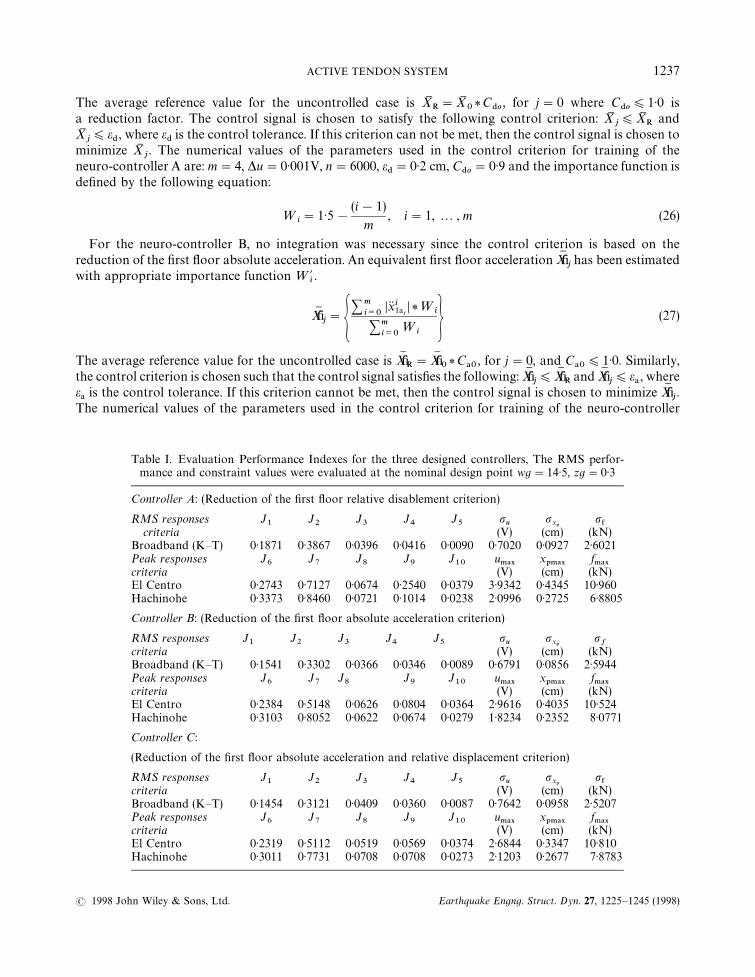
The robustness of the neuro-controller C is evaluated by computing the uncontrolled and controlledresponses of the structure for three different types of uncertainties, introduced by modifying some parametersof the system. These parameter modification are considered unmodelled since the structure was controlledwith the original neuro-controller C, trained on the unmodified structure. The first uncertainty representeda type of malfunction which caused a ten fold increase in the time delay. The second uncertainty representeda modification of the structural parameters, possibly caused by damage. It was modelled by modifying thestate space parameters of the evaluation model by $15 per cent. The third uncertainty simulated the case ofa partial sensor failure and, it was modelled by adding a random error of $0)3 V to the sensor feedback. Theperformance of the neuro-controller C under these unmodelled parameter modifications is summarized inTable II. It is clear that the neuro-controller was still able to perform well, even though the performance is
1242 K. BANI-HANI AND J. GHABOUSSI
( 1998 John Wiley & Sons, Ltd. Earthquake Engng. Struct. Dyn. 27, 1225—1245 (1998)
Figure 10. Comparison between the system responses with different cases of uncertainities and the case of the controlled system withoutuncertainities (neuro-controller C)
somewhat degraded from that of the perfectly modelled case. Figure 10 shows the responses of the systemwith the three different cases of parameter modifications.
CONCLUDING REMARKS
Three neuro-controllers were designed, trained and evaluated in this study. The results of this study showthat a neural network can be successfully implemented in structural control. Neuro-controllers have manyadvantages over the mathematically formulated control algorithms. While learning to control the structure,they also learn to compensate for the time delays and the actuator dynamics and, they learn to account for
ACTIVE TENDON SYSTEM 1243
( 1998 John Wiley & Sons, Ltd. Earthquake Engng. Struct. Dyn. 27, 1225—1245 (1998)
the actuator saturation. We have demonstrated the robustness of the neuro-controllers with results thatshow their effectiveness, without significant degradations in their performance, under uncertainities repre-sented by unmodelled parameter changes. This study has also demonstrated the effectiveness of theneuro-controllers with minimal feedback, which in this case included the first floor absolute acceleration andthe actuator displacement. Because of their inherent capability to learn complex nonlinear relationships,neural networks are also effective in nonlinear control problems. In summary, neuro-controllers are effectivein structural control and have many advantages over mathematically formulated control algorithms. Theperformance of neuro-controllers will soon be experimentally verified by the authors in a planned experimenton the three-storey model with the same control system as was used in this study.
The SIMULINK programs which contain the connection weights for the emulator neural network and thethree neuro-controllers are available on request from Prof. Jamshid Ghaboussi via e-mail address [email protected].
ACKNOWLEDGEMENT
The research reported in this paper was funded by National Science Foundation Grant CMS-95-003209.This support is gratefully acknowledged.
REFERENCES
1. K. Bani-Hani and J. Ghaboussi, ‘Nonlinear structural control using neural networks’, accepted for publication, J. Engng Mech. Div.ASCE 124(3), 319—328 (1998).
2. J. Ghaboussi, ‘Some applications of neural networks in structural engineering’, Proc. Structures Cong. ’94, ASCE, Atlanta, GA,1994.
3. J. Ghaboussi and K. Bani-Hani, ‘Neural network based nonlinear structural control methods’, Proc. 2nd Int. ¼orkshop on StructuralControl, IASC, Hong Kong, 18—21 December, 1996.
4. J. Ghaboussi, and A. Joghataie, ‘Active control of structures using neural networks’, J. Engng Mech. Div. ASCE 121(4), 555—567(1995).
5. A. Joghataie and J. Ghaboussi, ‘Neural networks and fuzzy logic in structural control’, Proc. 1st ¼orld Conf. on Structural Control,Los Angeles, CA, 1994.
6. A. Joghataie and J. Ghaboussi, ‘A comparative study of learning methods and mathematical algorithms in structural control’, Proc.11th ¼orld Conf. on Earthquake Engineering, Acapulco, Mexico, 1996.
7. K. Nikzad, J. Ghaboussi and S. Paul, ‘A study of actuator dynamics and delay compensation using neuro-controllers’, J. EngngMech. Div. ASCE 122, 966—975 (1996).
8. K. Nikzad, ‘A study of neural and conventional control paradigms in active digital structural control, Ph.D dissertation, Dept. ofCivil Engineering, University of Illinois, Urban-Champaign, 1992.
9. G. W. Housner, S. F. Masri and A. G. Chassiakos (eds) Proc. 1st ¼orld Conf. on Structural Control, 1 WCSC, 3—5 Aug. 1994, LosAngeles, CA 1994.
10. H. M. Chen, K. H. Tsai, G. Z. Qi and J. C. S. Yang, ‘Neural network for structural control’, J. Comput. Civil Engng. ASCE 9(2),168—176 (1995).
11. The Math Works, Inc., SIMº¸INK, Natick, MA, 1994.12. S. J. Dyke, B. F. Spencer, B. Quast and M. K. Sain, ‘The role of control-structure interaction in protective system design’, J. Engng
Mech. Div. ASCE 121(2) 322—338 (1995).13. J. Ghaboussi, J. H. Garrett and X. Wu, ‘Material modeling with neural networks,’ Proceedings of the Int. Conf. on Numerical
Methods in Engineering: ¹heory and Applications, Swansea, U.K., 1990, pp. 701—717.14. J. Ghaboussi, J. H. Garrett and X. Wu, ‘Knowledge-based modeling behavior with neural networks’, J. Engng Mech. Div. ASCE
117(1), 132—153 (1991).15. X. Wu, ‘Neural network based material modelling, Ph.D dissertation, Dept. of Civil Engineering, University of Illinois, Urban-
Champaign, 1991.16. A. Joghataie, J. Ghaboussi and X. Wu, ‘Learning and architecture determination through automatic node generation’, Proc. Int.
Conf. on Artificial Neural Networks in Engineering, St. Louis, 1995.17. S. E. Fahlman, ‘Faster learning variations on error backpropagation: an emperical study’, Carnegie-Mellon Summer ¼orkshop on
Neural Networks, 1988.18. T. Ash, ‘Dynamics node creation in backpropagation networks’, Proc. Int. Joint Conf. on Neural Network (IJCNN), Washington
D.C., 1989, June, Vol. II, pp. 623—629.19. L. L. Chung, A. M. Reinhorn and T. T. Soong, ‘Experiments on active control of seismic structures’, J. Engng Mech. Div. ASCE 114,
241—256 (1988).
1244 K. BANI-HANI AND J. GHABOUSSI
( 1998 John Wiley & Sons, Ltd. Earthquake Engng. Struct. Dyn. 27, 1225—1245 (1998)

20. The Math Works, Inc., MA¹¸AB, Natick, MA, 1994.21. E. L. Wilson, I. Farhoomand and K. J. Bathe, ‘Nonlinear dynamic analysis of complex structures’, Earthquake Engng. Struct. Dyn.
1(2), (1972).22. B. F. Spencer, J. Suhardjo and M. K. Sain, ‘Frequency domain optimal control strategies for aseismic protection’, J. Engng Mech.
Div. ASCE 120, 135—158 (1994).23. T. T. Soong, Active Structural Control, ¹heory and Practice, Longman Scientific and Technical, 1990.24. T. T. Soong, A. M. Reinhorn and Y. P. Wang, ‘Full scale implementation of active control, design and simulation’, J. Struct. Engng
Div. ASCE 117, 11, 3516—3536 (1991).
ACTIVE TENDON SYSTEM 1245
( 1998 John Wiley & Sons, Ltd. Earthquake Engng. Struct. Dyn. 27, 1225—1245 (1998)