Embed Size (px)
Citation preview

Neuroradiology For The Chiropractic Neurologist
Joseph S. Ferezy, D.C.
Radiology• Radiology is the medical specialty involved with
imaging technologies to diagnose and sometimes treat diseases.
• Originally it was dealing only with the medical use of electromagnetic energy emitted by X-ray machines or other such radiation devices for the purpose of obtaining visual information as part of medical imaging. Radiology that involves use of x-ray is called roentgenology.
• Modern day radiological imaging is no longer limited to the use of x-rays, and now includes technology-intensive imaging with high frequency sound waves, magnetic fields, and radioactivity.

Neuroradiology• A subspecialty of radiology focusing on the diagnosis
and characterization of abnormalities of the central and peripheral nervous system, spine, and head and neck.
• Interventional neuroradiology is a further subspecialization which adds an additional year or two of training. This area involves endovascular or minimally invasive diagnosis and treatment of central nervous system or head and neck lesions such as tumors, aneurysms, vascular malformations, or stroke.
Divisions of Neuroradiology
• Plain film radiography.
• Computed tomography (CT).
• Magnetic resonance imaging (MRI).
• Ultrasound.
• Angiography.
Plain Film Radiography
• Plain radiography is still widely utilized though on a more and more limited number of conditions.– Good Basic Screening Tool– Readily Available– Inexpensive– Relatively Safe
X-Ray History• In 1887 Nikola Tesla began to investigate X-rays. In 1895,
Wilhelm Röntgen began observing and further documenting X-rays while experimenting with vacuum tubes.
• One of the first X-ray photographs was made of the hand of Röntgen's wife. The image displayed both her wedding ring and bones. On January 18, 1896 an X-ray machine was formally displayed.
• X-Rays were advertised as the new scientific wonder and seized upon by entertainers. Circus patrons viewed their own skeletons and were given pictures of their own bony hands wearing silhouetted jewelry.
• In the 1940s and 50s, fluoroscopes (real time X-ray machines) were used in stores to help sell footwear.
• As the harmful effects of X-ray radiation were properly considered, they finally fell out of use.
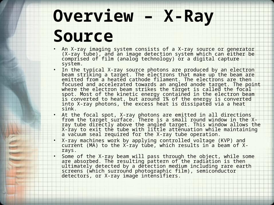
Overview – X-Ray Source• An X-ray imaging system consists of a X-ray source or generator (X-ray tube),
and an image detection system which can either be comprised of film (analog technology) or a digital capture system.
• In the typical X-ray source photons are produced by an electron beam striking a target. The electrons that make up the beam are emitted from a heated cathode filament. The electrons are then focused and accelerated towards an angled anode target. The point where the electron beam strikes the target is called the focal spot. Most of the kinetic energy contained in the electron beam is converted to heat, but around 1% of the energy is converted into X-ray photons, the excess heat is dissipated via a heat sink.
• At the focal spot, X-ray photons are emitted in all directions from the target surface. There is a small round window in the X-ray tube directly above the angled target. This window allows the X-ray to exit the tube with little attenuation while maintaining a vacuum seal required for the X-ray tube operation.
• X-ray machines work by applying controlled voltage (KVP) and current (MA) to the X-ray tube, which results in a beam of X-rays.
• Some of the X-ray beam will pass through the object, while some are absorbed. The resulting pattern of the radiation is then ultimately detected by a detection medium including rare earth screens (which surround photographic film), semiconductor detectors, or X-ray image intensifiers.
The X-Ray Machine
• The heart of an X-ray machine is an electrode pair -- a cathode and an anode -- that sits inside a glass vacuum tube.
• The cathode is a heated filament. • The machine passes current through the
filament, heating it up. The heat sputters electrons off of the filament surface.
• The positively-charged anode, a flat disc made of tungsten, draws the electrons across the tube.

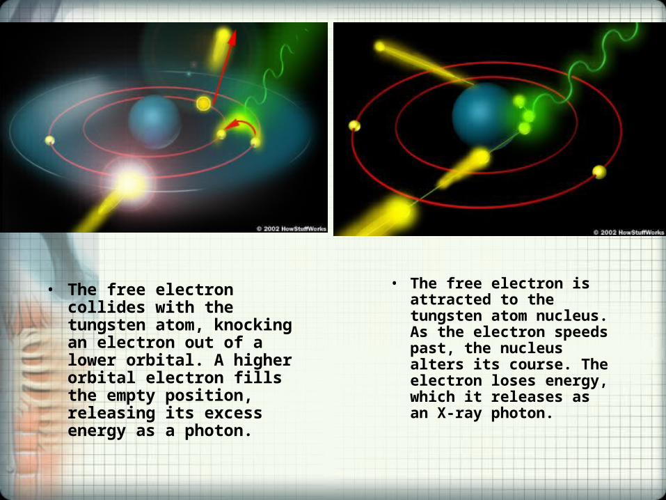
• The free electron collides with the tungsten atom, knocking an electron out of a lower orbital. A higher orbital electron fills the empty position, releasing its excess energy as a photon.
• The free electron is attracted to the tungsten atom nucleus. As the electron speeds past, the nucleus alters its course. The electron loses energy, which it releases as an X-ray photon.
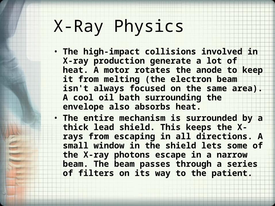
X-Ray Physics• The high-impact collisions involved in X-ray
production generate a lot of heat. A motor rotates the anode to keep it from melting (the electron beam isn't always focused on the same area). A cool oil bath surrounding the envelope also absorbs heat.
• The entire mechanism is surrounded by a thick lead shield. This keeps the X-rays from escaping in all directions. A small window in the shield lets some of the X-ray photons escape in a narrow beam. The beam passes through a series of filters on its way to the patient.
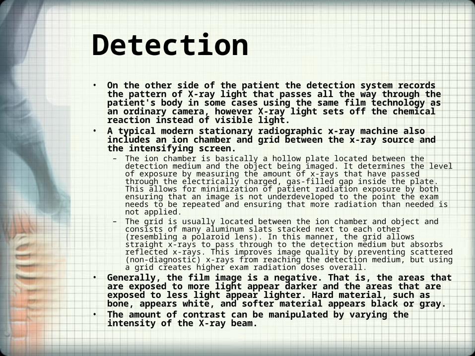
Detection• On the other side of the patient the detection system records the pattern of
X-ray light that passes all the way through the patient's body in some cases using the same film technology as an ordinary camera, however X-ray light sets off the chemical reaction instead of visible light.
• A typical modern stationary radiographic x-ray machine also includes an ion chamber and grid between the x-ray source and the intensifying screen.
– The ion chamber is basically a hollow plate located between the detection medium and the object being imaged. It determines the level of exposure by measuring the amount of x-rays that have passed through the electrically charged, gas-filled gap inside the plate. This allows for minimization of patient radiation exposure by both ensuring that an image is not underdeveloped to the point the exam needs to be repeated and ensuring that more radiation than needed is not applied.
– The grid is usually located between the ion chamber and object and consists of many aluminum slats stacked next to each other (resembling a polaroid lens). In this manner, the grid allows straight x-rays to pass through to the detection medium but absorbs reflected x-rays. This improves image quality by preventing scattered (non-diagnostic) x-rays from reaching the detection medium, but using a grid creates higher exam radiation doses overall.
• Generally, the film image is a negative. That is, the areas that are exposed to more light appear darker and the areas that are exposed to less light appear lighter. Hard material, such as bone, appears white, and softer material appears black or gray.
• The amount of contrast can be manipulated by varying the intensity of the X-ray beam.
Computed Radiography (CR) Detection• Uses standard x-ray hardware.• CR replaces film (screen, film and cassette) with an imaging plate
coated with storage phosphors to capture X-rays as they pass through the patient.
• After this exposure, the plate is "read," or scanned with a laser beam, which stimulates the phosphors to release visible light in proportion and corresponding to the local X-ray exposure.
• This light is captured and converted into an electrical signal, which is converted to data that can be recorded on laser-printed film or transmitted and stored digitally, as well as manipulated or enhanced.
– greater image contrast– sharper edges– tissue only
• CR expands and expedites image availability, can reduce image retakes and duplication costs, while improving workflow and productivity as compared to traditional film screen.
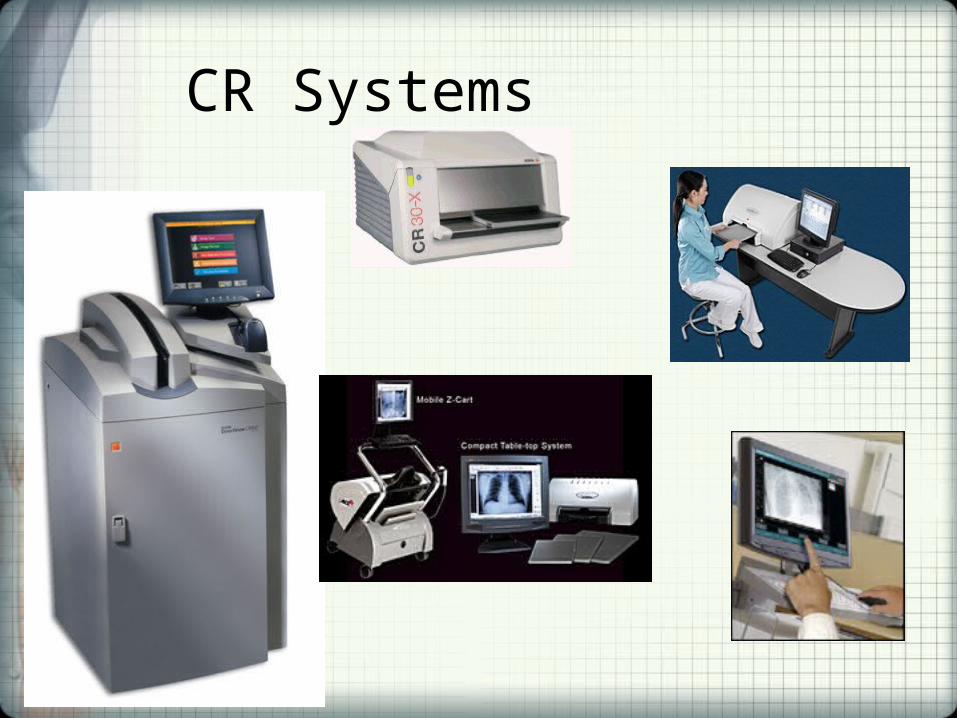
CR Systems
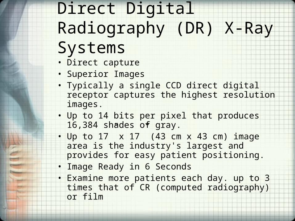
Direct Digital Radiography (DR) X-Ray Systems• Direct capture• Superior Images • Typically a single CCD direct digital receptor
captures the highest resolution images. • Up to 14 bits per pixel that produces 16,384 shades of
gray. • Up to 17” x 17” (43 cm x 43 cm) image area is the
industry's largest and provides for easy patient positioning.
• Image Ready in 6 Seconds• Examine more patients each day. up to 3 times that of
CR (computed radiography) or film

DR X-ray System
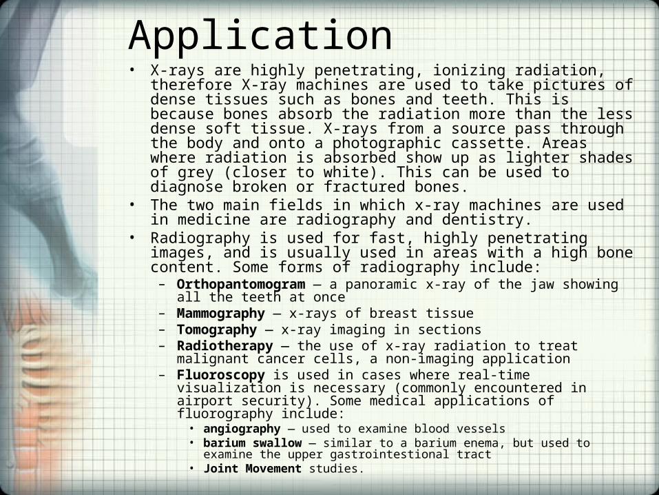
Application• X-rays are highly penetrating, ionizing radiation, therefore X-ray
machines are used to take pictures of dense tissues such as bones and teeth. This is because bones absorb the radiation more than the less dense soft tissue. X-rays from a source pass through the body and onto a photographic cassette. Areas where radiation is absorbed show up as lighter shades of grey (closer to white). This can be used to diagnose broken or fractured bones.
• The two main fields in which x-ray machines are used in medicine are radiography and dentistry.
• Radiography is used for fast, highly penetrating images, and is usually used in areas with a high bone content. Some forms of radiography include:
– Orthopantomogram — a panoramic x-ray of the jaw showing all the teeth at once
– Mammography — x-rays of breast tissue – Tomography — x-ray imaging in sections – Radiotherapy — the use of x-ray radiation to treat malignant cancer cells, a
non-imaging application– Fluoroscopy is used in cases where real-time visualization is necessary
(commonly encountered in airport security). Some medical applications of fluorography include:
• angiography — used to examine blood vessels• barium swallow — similar to a barium enema, but used to examine the upper
gastrointestional tract• Joint Movement studies.
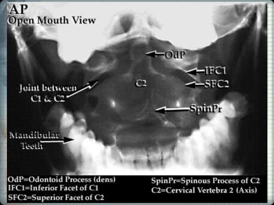
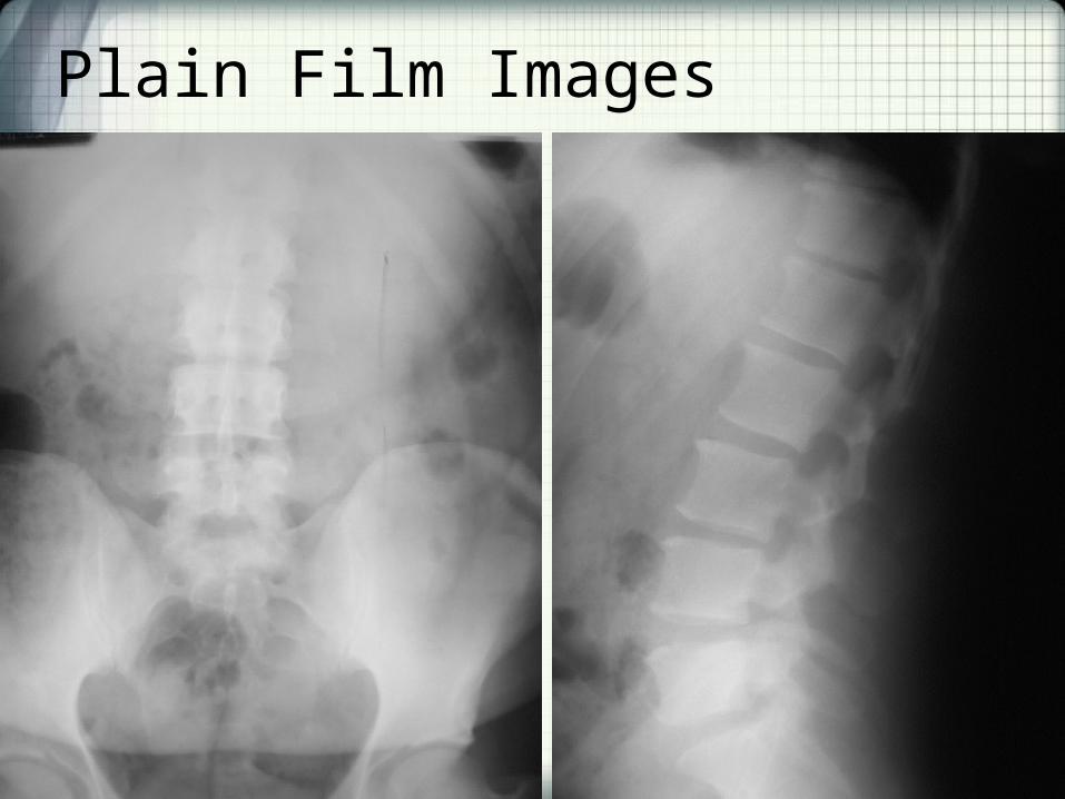
Plain Film Images
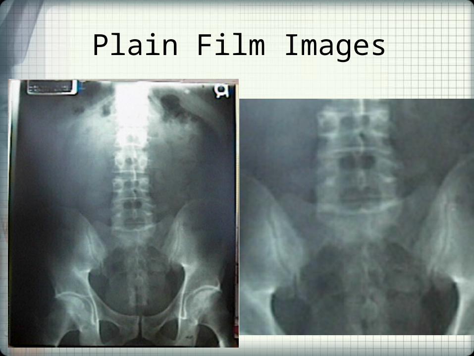
Plain Film Images
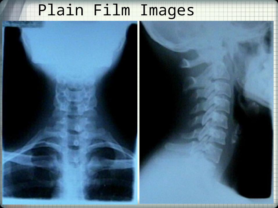
Plain Film Images
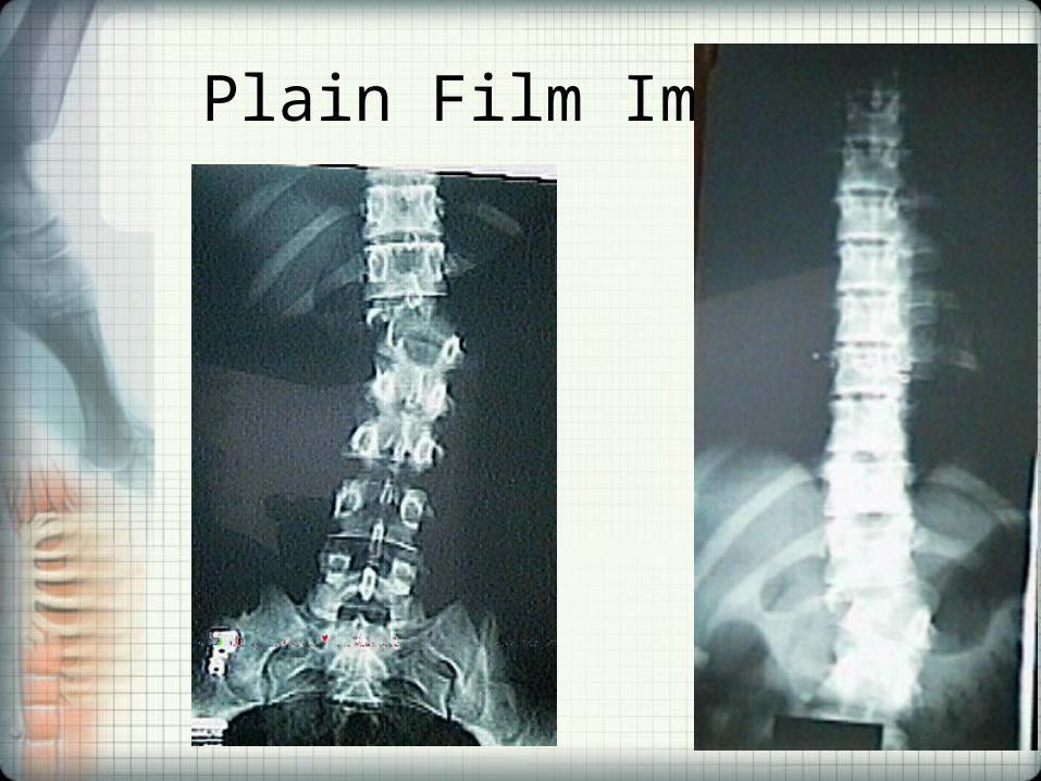
Plain Film Images
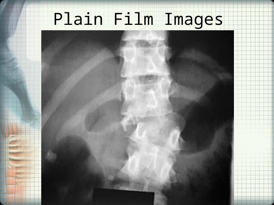
Plain Film Images
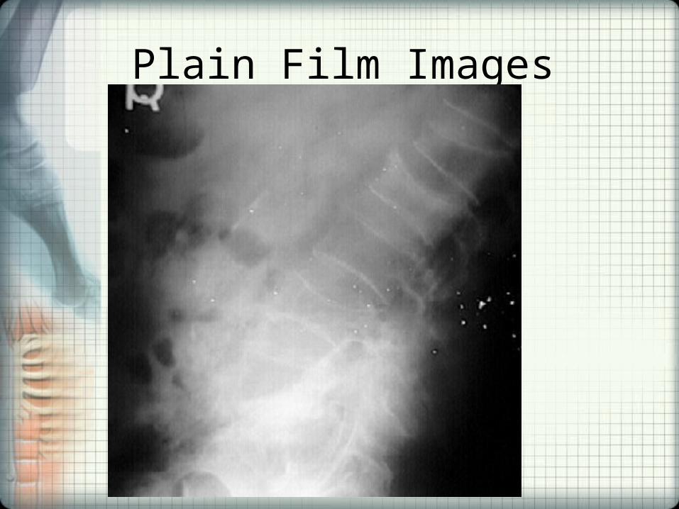
Plain Film Images
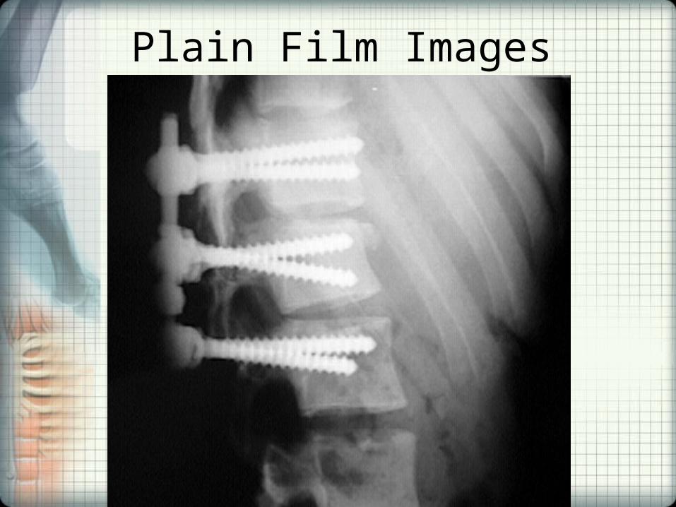
Plain Film Images

Computed Tomography• Computed tomography (CT) is an X-ray technique that
produces images of the body using an X-ray unit that rotates around your body and a computer to create cross-sectional images employing tomography. Digital geometry processing is used to generate a three-dimensional image of the inside of an object from a large series of two-dimensional X-ray images taken around a single axis of rotation.
• The word "tomography" is derived from the Greek tomos (slice) and graphein (to write).
• Although historically the images generated were in the axial or transverse plane (orthogonal to the long axis of the body), modern scanners allow this volume of data to be reformatted in various planes or even as volumetric (3D) representations of structures.
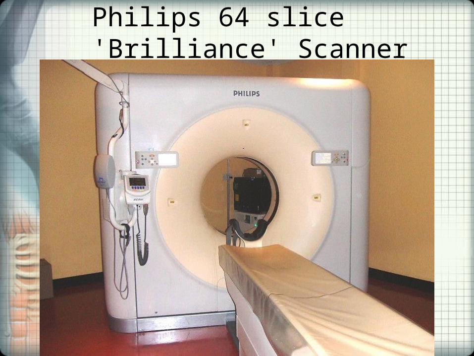
Philips 64 slice 'Brilliance' Scanner
The Process• During a CT scan, the patient lays on a table inside a
doughnut-shaped machine called a gantry. An X-ray tube inside the machine rotates around the body and sends small doses of radiation through it at various angles. As X-rays pass through your body, different tissues absorb different amounts of radiation.
• Detectors inside the gantry measure the radiation that has passed through your body and converts it into electrical signals. A computer gathers these signals and assigns them a color ranging from black to white, depending on signal intensity. The computer then assembles the images and displays them on a computer monitor.
The Patient’s Experience• Location - hospital or an outpatient facility • Length of the scan About an hour, depending on the preparation needed and whether
it includes the use of a contrast medium. The scan itself may take less than a minute on the newest machines. Most scans take just a few minutes to complete.
• Positioning - During the CT scan, the patient is placed on a narrow table that slides through the opening of the gantry. The patient may lie on their back, side or stomach, depending on the area to be scanned. The table can be raised or lowered. Straps and pillows may help the patient stay in position. During a CT scan of the head, the table may be fitted with a special cradle that holds the head still.
• What the device does - As the X-ray tube rotates around the body, the table slowly moves through the gantry. While moving the patient may be asked to hold their breath to avoid blurring the images. Clicking and whirring noises may be heard. Each rotation yields several images of thin slices of your body.
• The technologist - A technologist in a shielded room supervises the CT scan and monitors the images as they appear on the computer screen. The technologist can communicate with the patient via intercom.
• How it feels - CT scans are painless. If the exam involves use of an intravenous contrast medium, the patient may feel a brief sensation of heat or experience a metallic taste in the mouth. If the contrast medium was through an enema — to help highlight the lower gastrointestinal region the patient may feel a sense of fullness or cramping.
• Back to normal - After the exam patients return to their normal routine. If given a contrast medium, the patient may receive special instructions. They may be asked to wait for a short time in the radiology department to ensure that they feel well after the exam. After the scan, fluids are encouraged to help your kidneys remove the medium from the body.
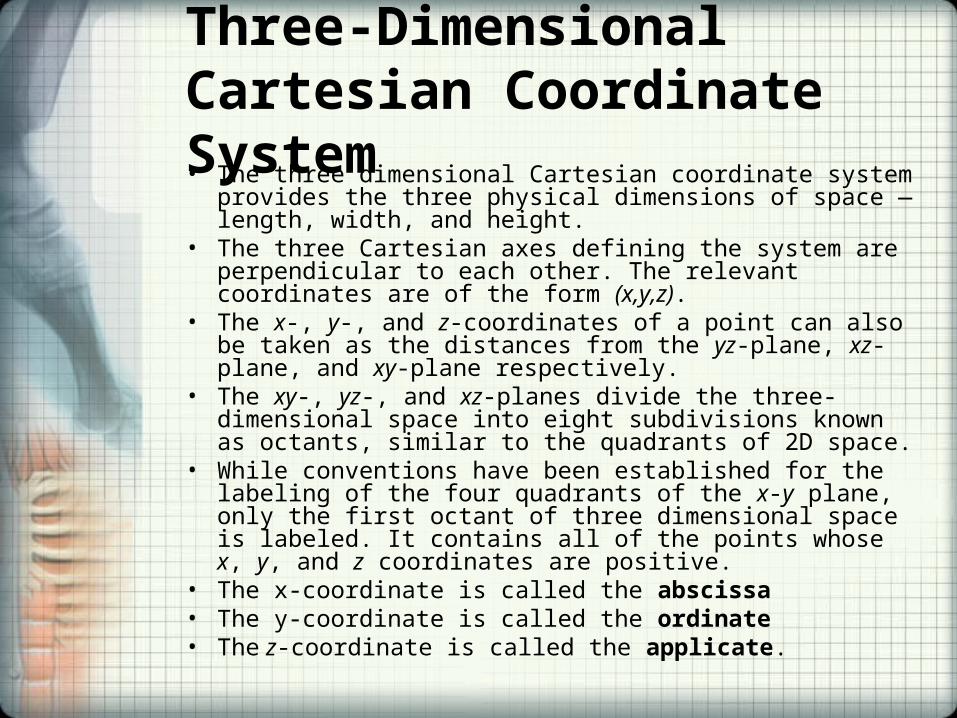
Three-Dimensional Cartesian Coordinate System• The three dimensional Cartesian coordinate system provides the
three physical dimensions of space — length, width, and height. • The three Cartesian axes defining the system are perpendicular
to each other. The relevant coordinates are of the form (x,y,z). • The x-, y-, and z-coordinates of a point can also be taken as the
distances from the yz-plane, xz-plane, and xy-plane respectively. • The xy-, yz-, and xz-planes divide the three-dimensional space
into eight subdivisions known as octants, similar to the quadrants of 2D space.
• While conventions have been established for the labeling of the four quadrants of the x-y plane, only the first octant of three dimensional space is labeled. It contains all of the points whose x, y, and z coordinates are positive.
• The x-coordinate is called the abscissa• The y-coordinate is called the ordinate• The z-coordinate is called the applicate.
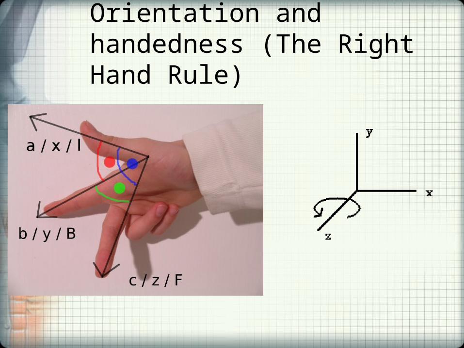
Orientation and handedness (The Right Hand Rule)
Tomography• A form of tomography can be performed by moving
the X-ray source and detector during an exposure. Anatomy at the target level remains sharp, while structures at different levels are blurred. By varying the extent and path of motion, a variety of effects can be obtained, with variable depth of field and different degrees of blurring of 'out of plane' structures.
• Although largely obsolete, conventional tomography is still used in specific situations such as dental imaging or in intravenous urography.
Scout/pilot/topogram
• A Scout image is used in planning the exam and to establish where the target organs are located. The beginning and end of the scan are set by the target region and the location of the patient on the table. Once the Scout image is created it is used to determine the extent of the desired Axial/Helical scan. During the Scout scan the gantry is rotated to a fixed position and the table is translated as x-ray is delivered. The image appears similar to a radiograph.
Axial Images
• In axial "step and shoot" acquisitions each slice/volume is taken and then the table is incremented to the next location. In multislice scanners each location is multiple slices and represents a volume of the patient anatomy.
• Tomographic reconstruction is used to generate Axial images.
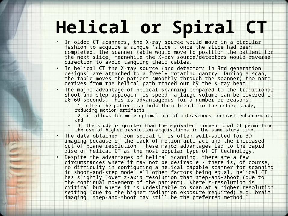
Helical or Spiral CT• In older CT scanners, the X-ray source would move in a circular fashion to acquire
a single 'slice', once the slice had been completed, the scanner table would move to position the patient for the next slice; meanwhile the X-ray source/detectors would reverse direction to avoid tangling their cables.
• In helical CT the X-ray source (and detectors in 3rd generation designs) are attached to a freely rotating gantry. During a scan, the table moves the patient smoothly through the scanner; the name derives from the helical path traced out by the X-ray beam.
• The major advantage of helical scanning compared to the traditional shoot-and-step approach, is speed; a large volume can be covered in 20-60 seconds. This is advantageous for a number or reasons:
– 1) often the patient can hold their breath for the entire study, reducing motion artifacts,– 2) it allows for more optimal use of intravenous contrast enhancement, and– 3) the study is quicker than the equivalent conventional CT permitting the use of higher
resolution acquisitions in the same study time.• The data obtained from spiral CT is often well-suited for 3D imaging because of the
lack of motion artifact and the increased out of plane resolution. These major advantages led to the rapid rise of helical CT as the most popular type of CT technology.
• Despite the advantages of helical scanning, there are a few circumstances where it may not be desirable - there is, of course, no difficulty in configuring a helical capable scanner for scanning in shoot-and-step mode. All other factors being equal, helical CT has slightly lower z-axis resolution than step-and-shoot (due to the continual movement of the patient). Where z-resolution is critical but where it is undesirable to scan at a higher resolution setting (due to the higher radiation exposure required) e.g. brain imaging, step-and-shoot may still be the preferred method.
Cine
• A cine acquisition is used when the temporal nature is important. This is used in Perfusion applications to evaluate blood flow, blood volume and mean transit time. Cine is a time sequence of axial images.
DRR
• A Digitally Reconstructed Radiograph is a simulation of a conventional 2D x-ray image, created from computed tomography (CT) data.
• A radiograph, or conventional x-ray image, is a single 2D view of total x-ray absorption through the body along a given axis. Two objects in front of one another will overlap in the image. By contrast, a 3D CT image gives a volumetric representation.

Multislice CT• Multislice CT scanners are similar in concept to the helical or spiral CT
but there are multiple detector rings. Current models (2007) have up to 3 rotations per second, and isotropic resolution of 0.35 mm voxels with z-axis scan speed of up to 18 cm/s. This resolution exceeds that of High Resolution CT techniques with single-slice scanners, yet it is practical to scan adjacent, or overlapping, slices - however, image noise and radiation exposure significantly limit the use of such resolutions.
• The major benefit of multi-slice CT is the increased speed of volume coverage. This allows large volumes to be scanned at the optimal time following intravenous contrast administration; this has particularly benefitted CT angiography techniques - which rely heavily on precise timing to ensure good demonstration of arteries.
• Computer power permits increasing the postprocessing capabilities on workstations. Bone suppression, volume rendering in real time, with a natural visualization of internal organs and structures, and automated volume reconstruction really change the way diagnostic is performed on CT studies using this model have become true volumetric scanners. The ability of multi-slice scanners to achieve isotropic resolution even on routine studies means that maximum image quality is not restricted to images in the axial plane - and studies can be freely viewed in any desired plane.
Dynamic volume CT
• This 320-slice CT scanner, with its 16 cm anatomical coverage, can scan entire organs such as heart and brain, in just one single rotation, thereby also enabling dynamic processes such as blood flow and function to be observed.
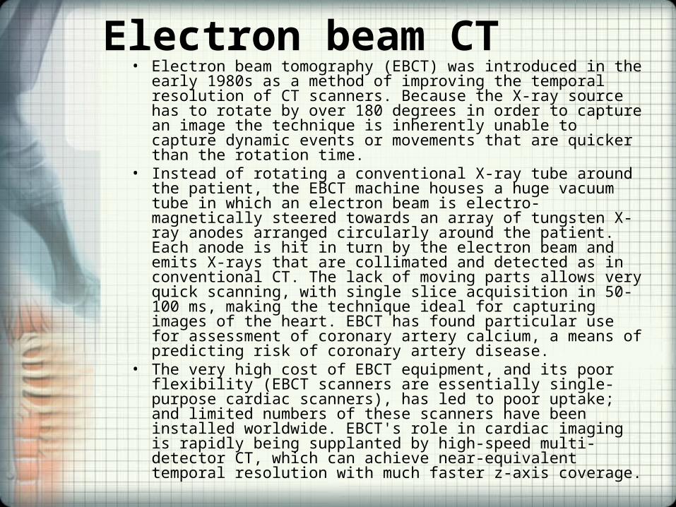
Electron beam CT• Electron beam tomography (EBCT) was introduced in the early
1980s as a method of improving the temporal resolution of CT scanners. Because the X-ray source has to rotate by over 180 degrees in order to capture an image the technique is inherently unable to capture dynamic events or movements that are quicker than the rotation time.
• Instead of rotating a conventional X-ray tube around the patient, the EBCT machine houses a huge vacuum tube in which an electron beam is electro-magnetically steered towards an array of tungsten X-ray anodes arranged circularly around the patient. Each anode is hit in turn by the electron beam and emits X-rays that are collimated and detected as in conventional CT. The lack of moving parts allows very quick scanning, with single slice acquisition in 50-100 ms, making the technique ideal for capturing images of the heart. EBCT has found particular use for assessment of coronary artery calcium, a means of predicting risk of coronary artery disease.
• The very high cost of EBCT equipment, and its poor flexibility (EBCT scanners are essentially single-purpose cardiac scanners), has led to poor uptake; and limited numbers of these scanners have been installed worldwide. EBCT's role in cardiac imaging is rapidly being supplanted by high-speed multi-detector CT, which can achieve near-equivalent temporal resolution with much faster z-axis coverage.
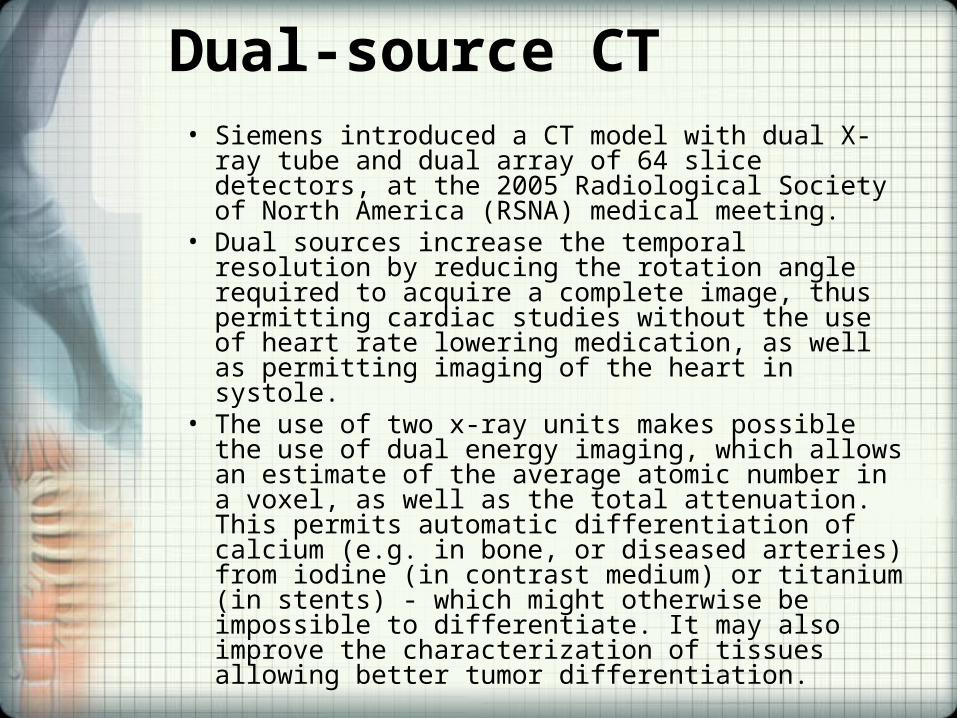
Dual-source CT• Siemens introduced a CT model with dual X-ray tube
and dual array of 64 slice detectors, at the 2005 Radiological Society of North America (RSNA) medical meeting.
• Dual sources increase the temporal resolution by reducing the rotation angle required to acquire a complete image, thus permitting cardiac studies without the use of heart rate lowering medication, as well as permitting imaging of the heart in systole.
• The use of two x-ray units makes possible the use of dual energy imaging, which allows an estimate of the average atomic number in a voxel, as well as the total attenuation. This permits automatic differentiation of calcium (e.g. in bone, or diseased arteries) from iodine (in contrast medium) or titanium (in stents) - which might otherwise be impossible to differentiate. It may also improve the characterization of tissues allowing better tumor differentiation.

256+ slice CT• At RSNA 2007, Philips announced a 256-slice
scanner, while Toshiba announced a "dynamic volume" scanner based on 320 slices.
• The majority of published data with regard to both technical and clinical aspects of the systems have been related to the prototype unit made by Toshiba Medical Systems.
• The technology currently remains in a development phase but has demonstrated the potential to significantly reduce radiation exposure by eliminating the requirement for a helical examination in both cardiac CT angiography and whole brain perfusion studies for the evaluation of stroke.
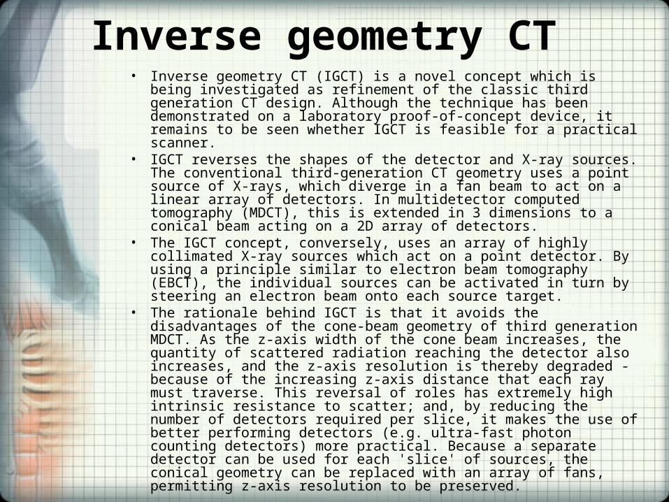
Inverse geometry CT• Inverse geometry CT (IGCT) is a novel concept which is being
investigated as refinement of the classic third generation CT design. Although the technique has been demonstrated on a laboratory proof-of-concept device, it remains to be seen whether IGCT is feasible for a practical scanner.
• IGCT reverses the shapes of the detector and X-ray sources. The conventional third-generation CT geometry uses a point source of X-rays, which diverge in a fan beam to act on a linear array of detectors. In multidetector computed tomography (MDCT), this is extended in 3 dimensions to a conical beam acting on a 2D array of detectors.
• The IGCT concept, conversely, uses an array of highly collimated X-ray sources which act on a point detector. By using a principle similar to electron beam tomography (EBCT), the individual sources can be activated in turn by steering an electron beam onto each source target.
• The rationale behind IGCT is that it avoids the disadvantages of the cone-beam geometry of third generation MDCT. As the z-axis width of the cone beam increases, the quantity of scattered radiation reaching the detector also increases, and the z-axis resolution is thereby degraded - because of the increasing z-axis distance that each ray must traverse. This reversal of roles has extremely high intrinsic resistance to scatter; and, by reducing the number of detectors required per slice, it makes the use of better performing detectors (e.g. ultra-fast photon counting detectors) more practical. Because a separate detector can be used for each 'slice' of sources, the conical geometry can be replaced with an array of fans, permitting z-axis resolution to be preserved.

Peripheral Quantitative Computed Tomography (pQCT)
• pQCT-measurement at distal radius (cross-sectional image)• pQCT or QCT devices are optimized for high precision
measurements of physical properties of bone such as bone density and bone geometry. In comparison to the commonly used DXA system which measures bone mass only, QCT systems can determine bone strength as a mechanical property and the resulting fracture risk. Hence one outcome parameter is the Stress-Strain Index (SSI) comparing bone strength to results of three point bending tests commonly used for mechanical material tests.
• Typical application is Osteoporosis diagnostics where single slices at the Tibia or the Radius are measured resulting in a very low local Radiation dose of 1-2 μSv.
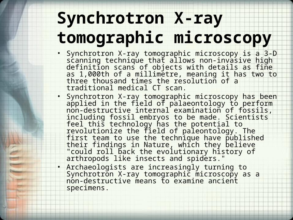
Synchrotron X-ray tomographic microscopy• Synchrotron X-ray tomographic microscopy is a 3-D scanning
technique that allows non-invasive high definition scans of objects with details as fine as 1,000th of a millimetre, meaning it has two to three thousand times the resolution of a traditional medical CT scan.
• Synchrotron X-ray tomographic microscopy has been applied in the field of palaeontology to perform non-destructive internal examination of fossils, including fossil embryos to be made. Scientists feel this technology has the potential to revolutionize the field of paleontology. The first team to use the technique have published their findings in Nature, which they believe "could roll back the evolutionary history of arthropods like insects and spiders."
• Archaeologists are increasingly turning to Synchrotron X-ray tomographic microscopy as a non-destructive means to examine ancient specimens.
X-ray Tomography
• X-ray Tomography is a branch of X-ray microscopy. A series of projection images are used to calculate a three dimensional reconstruction of an object. The technique has found many applications in materials science and later in biology and biomedical research. In terms of the latter, the National Center for X-ray Tomography (NCXT) is one of the principal developers of this technology, in particular for imaging whole, hydrated cells.
Why Choose a CT Scan?
• Acute Nervous System Bleeds• Diagnose bone disorders, such as bone tumors
and fractures. • Guide procedures such as surgery, biopsy and
radiation therapy. • Detect and monitor diseases such as cancer or
heart disease. • CT scans can be done even if you have a
pacemaker, internal defibrillator, vascular coils, slag, etc.
Adverse Effects of CT• Pregnancy. Recommend another type of exam to reduce the
possible risk of exposing the fetus to radiation. • Patients who have had excessive x-ray exposure. The
exposure is cumulative over a period of time.• Contrast Media
– Reactions to contrast medium - although rare, the contrast medium involved in a CT scan poses a slight risk of allergic reaction. Most reactions are mild and result in hives or itchiness.
– For people with asthma who become allergic to the contrast medium, the reaction can be an asthma attack.
– In rare instances, an allergic reaction can be serious and potentially life-threatening — including swelling in your throat or other areas of your body. Patients who experience hives, itchiness or swelling in the throat during or after the CT exam should be instructed to immediately tell the technologist or doctor.
– Kidney problems - Contrast material that's injected into the vein is removed from the body by the kidneys and could potentially cause further damage to the kidneys in some circumstances.
– Asthma or allergies. Patients who have had a prior reaction to contrast media or have Diabetes, asthma, allergies, heart disease, kidney problems or certain thyroid conditions may have an increased risk of a reaction to the contrast medium.
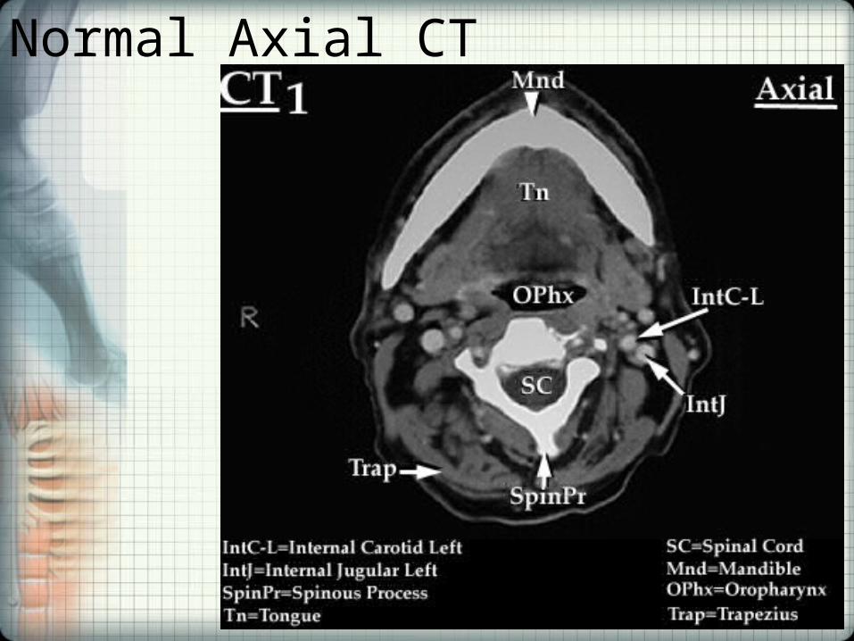
Normal Axial CT
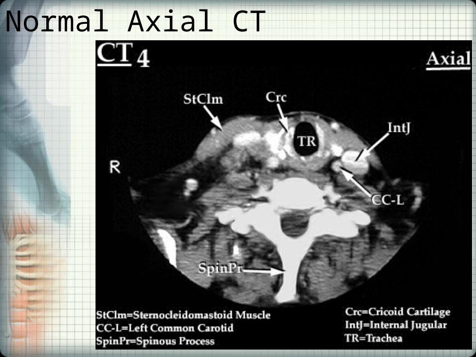
Normal Axial CT
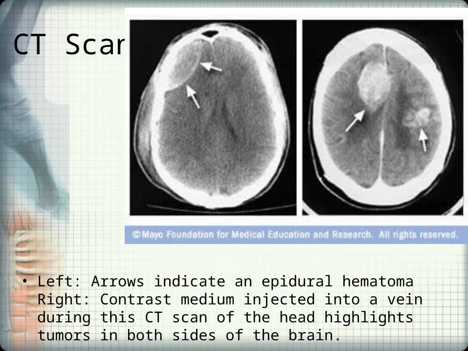
CT Scans
• Left: Arrows indicate an epidural hematoma Right: Contrast medium injected into a vein during this CT scan of the head highlights tumors in both sides of the brain.
Cases in Neurology
• Case 142
• Case 146
• Case 147
• Case 148
• Case 149
• Case 150
• Case 151
Radiological Topics Relative to the Practice of Chiropractic Neurology
• Fundamentals of CT Scanning: Video - Dr. Rowe
• Spondylolisthesis – Video - Dr. Rowe
• Whiplash – Video - Dr. Rowe
• Basic Bone Radiology – Video Dr. Rowe

Magnetic Resonance Imaging
• Magnetic resonance imaging (MRI), or Nuclear magnetic resonance imaging (NMRI), is primarily a medical imaging technique most commonly used in Radiology to visualize the structure and function of the body.
• It provides detailed images of the body in any plane. MRI provides much greater contrast between the different soft tissues of the body than does computed tomography (CT), making it especially useful in neurological, musculoskeletal, cardiovascular, and oncological imaging.
• Unlike CT, it uses no ionizing radiation, but uses a powerful magnetic field to align the (usually) hydrogen atoms in water in the body. Radiofrequency fields are used to systematically alter the alignment of this magnetization, causing the hydrogen nuclei to produce a rotating magnetic field detectable by the scanner.
MRI• MRI is a relatively new technology, which has been in use
for little more than 30 years (compared with over 110 years for X-ray radiography). The first MR Image was published in 1973 and the first study performed on a human took place on July 3, 1977.
• Magnetic resonance imaging was developed from knowledge gained in the study of nuclear magnetic resonance. In its early years the technique was referred to as nuclear magnetic resonance imaging (NMRI). However, as the word nuclear was associated in the public mind with ionizing radiation exposure it is generally now referred to simply as MRI.
• Scientists still use the term NMRI when discussing non-medical devices operating on the same principles.
• The term Magnetic Resonance Tomography (MRT) is also sometimes used.
Brief lay explanation of MRI physics• When a person lies in a scanner, the hydrogen nuclei (i.e., protons)
found in abundance in the human body in water molecules, align with the strong main magnetic field. A second electromagnetic field, which oscillates at radiofrequencies and is perpendicular to the main field, is then pulsed to push a proportion of the protons out of alignment with the main field. These protons then drift back into alignment with the main field, emitting a detectable radiofrequency signal as they do so.
• Since protons in different tissues of the body (e.g., fat vs. muscle) realign at different speeds, the different structures of the body can be revealed.
• Contrast agents may be injected intravenously to enhance the appearance of blood vessels, tumors or inflammation. Contrast agents may also be directly injected into a joint, in the case of MR arthrograms. Unlike CT scanning MRI uses no ionizing radiation and is generally a very safe procedure.
• Patients with some metal implants and cardiac pacemakers are prevented from having an MRI scan due to effects of the strong magnetic field and powerful radiofrequency pulses.
• MRI is used to image every part of the body, but is particularly useful in neurological conditions, disorders of the muscles and joints, for evaluating tumors and showing abnormalities in the heart and blood vessels.
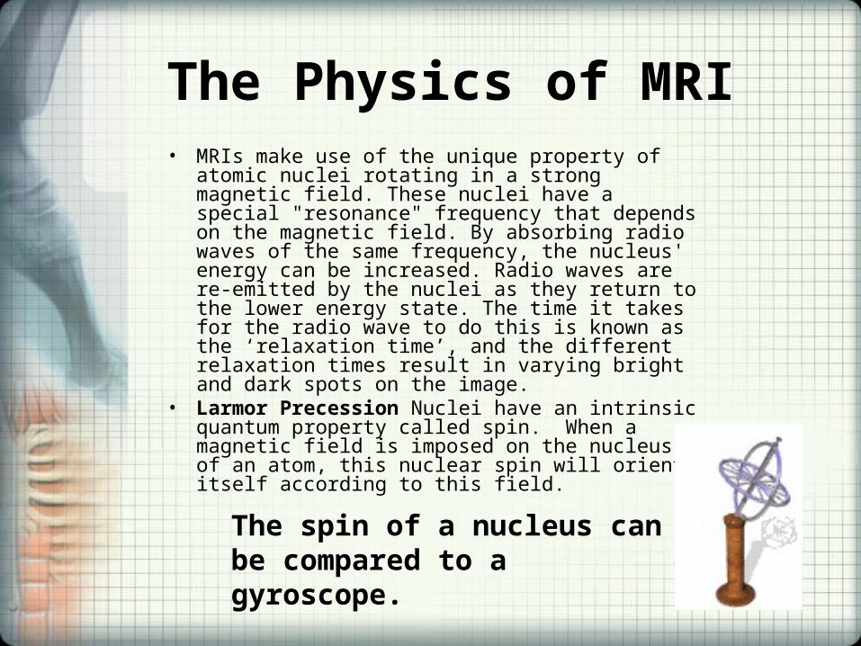
The Physics of MRI• MRIs make use of the unique property of atomic nuclei
rotating in a strong magnetic field. These nuclei have a special "resonance" frequency that depends on the magnetic field. By absorbing radio waves of the same frequency, the nucleus' energy can be increased. Radio waves are re-emitted by the nuclei as they return to the lower energy state. The time it takes for the radio wave to do this is known as the ‘relaxation time’, and the different relaxation times result in varying bright and dark spots on the image.
• Larmor Precession Nuclei have an intrinsic quantum property called spin. When a magnetic field is imposed on the nucleus of an atom, this nuclear spin will orient itself according to this field.
The spin of a nucleus can be compared to a gyroscope.
The Physics of MRI
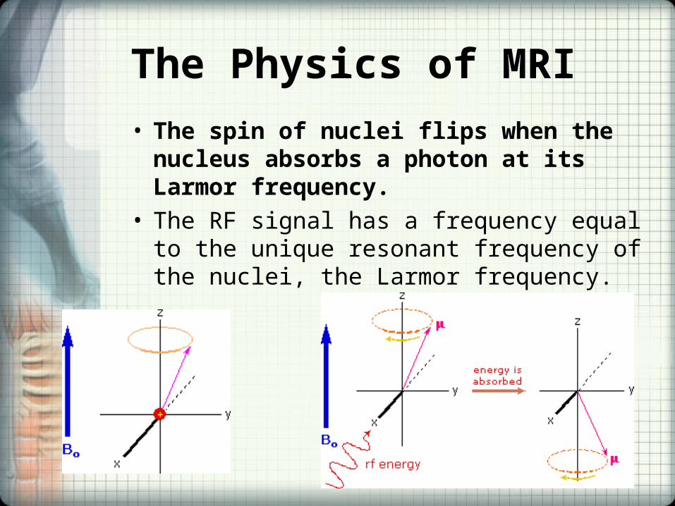
• The spin of nuclei flips when the nucleus absorbs a photon at its Larmor frequency.
• The RF signal has a frequency equal to the unique resonant frequency of the nuclei, the Larmor frequency.
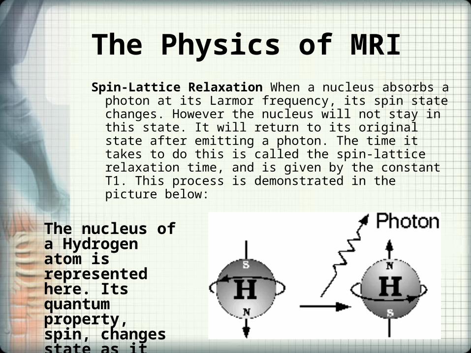
The Physics of MRISpin-Lattice Relaxation When a nucleus absorbs a
photon at its Larmor frequency, its spin state changes. However the nucleus will not stay in this state. It will return to its original state after emitting a photon. The time it takes to do this is called the spin-lattice relaxation time, and is given by the constant T1. This process is demonstrated in the picture below:
The nucleus of a Hydrogen atom is represented here. Its quantum property, spin, changes state as it emits a photon to its surroundings.
Spin-Spin Relaxation
• Another type of relaxation used in magnetic resonance imaging is spin-spin relaxation. Because the magnetic field varies, the nuclei's Larmor frequency will vary. Since they spin at different frequencies, the nuclei will gradually end up out of phase, or spin at different times. MRIs use the loss of signal due to the phase-difference between these nuclei to assist in creating the image.
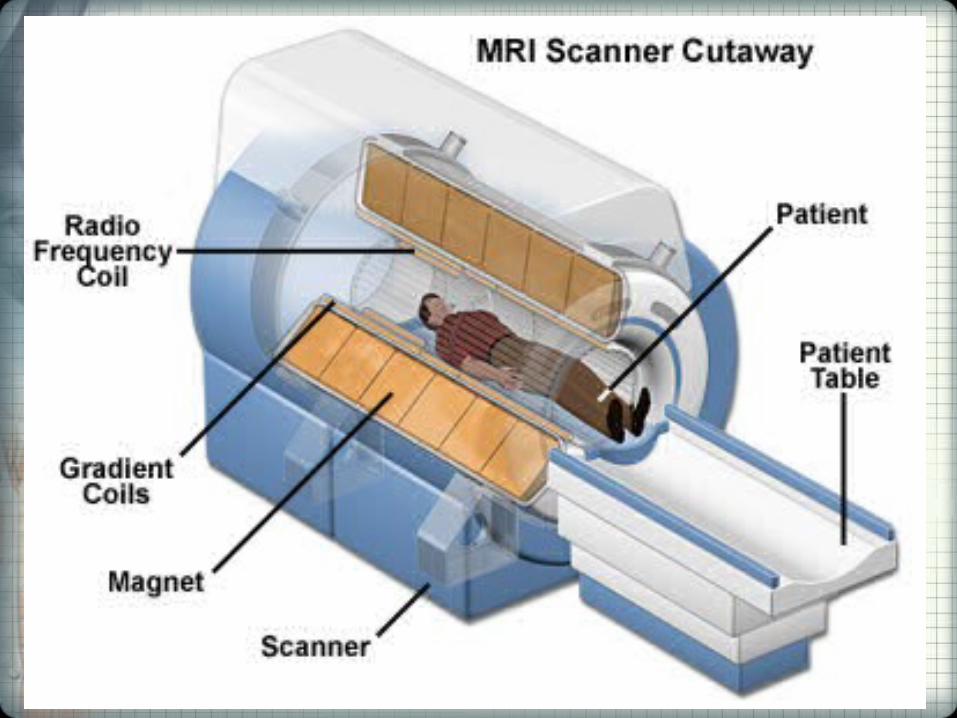
Scanner construction and operation - Magnets
• The major components of an MRI scanner: a static magnetic field, an RF transmitter and receiver, and three orthogonal, controllable magnetic gradients.
• The magnet is the largest and most expensive component of the scanner, and the remainder of the scanner is built around it.
• Just as important as the strength of the main magnet is its precision. The straightness of the magnetic lines within the center (or, as it is technically known, the iso-center) of the magnet needs to be near-perfect.
• Three types of magnets have been used:– Permanent magnet: Conventional magnets made from ferromagnetic materials (e.g., steel alloys
containing rare earth elements such as Neodymium) can be used to provide the static magnetic field. A permanent magnet that is powerful enough to be used in an MRI will be extremely large and bulky; they can weigh over 100 tons. Permanent magnets also present special safety issues; since their magnetic fields cannot be "turned off," ferromagnetic objects are virtually impossible to remove from them once they come into direct contact. Permanent magnets also require special care when they are being brought to their site of installation.
– Resistive electromagnet: A solenoid wound from copper wire is an alternative to a permanent magnet. An advantage is low initial cost, but field strength and stability are limited. The electromagnet requires considerable electrical energy during operation which can make it expensive to operate. This design is essentially obsolete.
– Superconducting electromagnet: When a niobium-titanium or niobium-tin alloy is cooled by liquid helium to 4K (−269°C, −452°F) it becomes a superconductor, losing resistance to flow of electrical current. An electromagnet constructed with superconductors can have extremely high field strengths, with very high stability. The construction of such magnets is extremely costly, and the cryogenic helium is expensive and difficult to handle. However, despite its cost, helium cooled superconducting magnets are the most common type found in MRI scanners today.
Scanner construction and operation - Magnets• Most superconducting magnets have their coils of superconductive wire
immersed in liquid helium, inside a vessel called a cryostat. Despite thermal insulation, ambient heat causes the helium to slowly boil off. Such magnets, therefore, require regular topping-up with liquid helium. Generally a cryocooler, also known as a coldhead, is used to recondense some helium vapor back into the liquid helium bath. Several manufacturers now offer 'cryogenless' scanners, where instead of being immersed in liquid helium the magnet wire is cooled directly by a cryocooler.
• Magnets are available in a variety of shapes. However, permanent magnets are most frequently 'C' shaped, and superconducting magnets most frequently cylindrical. However, C-shaped superconducting magnets and box-shaped permanent magnets have also been used.
• Magnetic field strength is an important factor in determining image quality. Higher magnetic fields increase signal-to-noise ratio, permitting higher resolution or faster scanning. However, higher field strengths require more costly magnets with higher maintenance costs, and have increased safety concerns. 1.0 - 1.5T field strengths are a good compromise between cost and performance for general medical use. However, for certain specialist uses (e.g., brain imaging), field strengths up to 3.0 T may be desirable.
• Continuing software development improves the quality of the images even with smaller magnets..
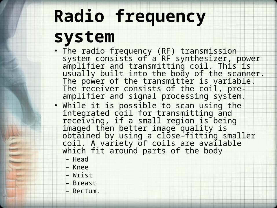
Radio frequency system• The radio frequency (RF) transmission system
consists of a RF synthesizer, power amplifier and transmitting coil. This is usually built into the body of the scanner. The power of the transmitter is variable. The receiver consists of the coil, pre-amplifier and signal processing system.
• While it is possible to scan using the integrated coil for transmitting and receiving, if a small region is being imaged then better image quality is obtained by using a close-fitting smaller coil. A variety of coils are available which fit around parts of the body– Head– Knee– Wrist– Breast– Rectum.
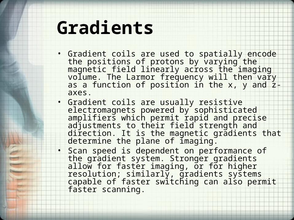
Gradients• Gradient coils are used to spatially encode the positions of
protons by varying the magnetic field linearly across the imaging volume. The Larmor frequency will then vary as a function of position in the x, y and z-axes.
• Gradient coils are usually resistive electromagnets powered by sophisticated amplifiers which permit rapid and precise adjustments to their field strength and direction. It is the magnetic gradients that determine the plane of imaging.
• Scan speed is dependent on performance of the gradient system. Stronger gradients allow for faster imaging, or for higher resolution; similarly, gradients systems capable of faster switching can also permit faster scanning.
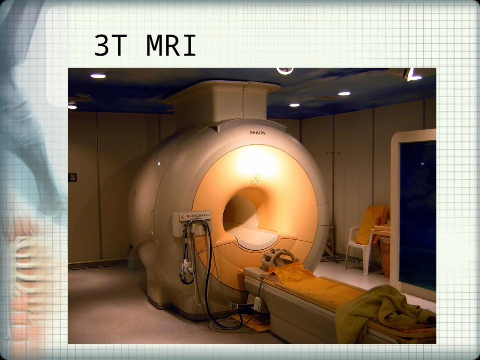
3T MRI
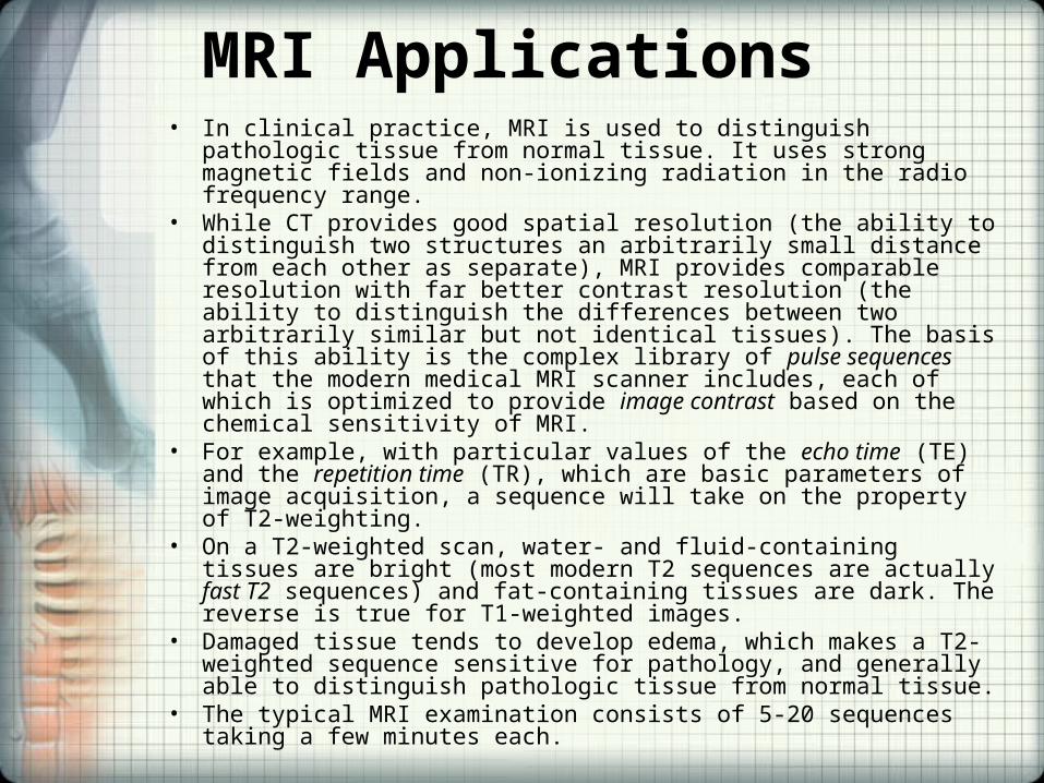
MRI Applications• In clinical practice, MRI is used to distinguish pathologic tissue from
normal tissue. It uses strong magnetic fields and non-ionizing radiation in the radio frequency range.
• While CT provides good spatial resolution (the ability to distinguish two structures an arbitrarily small distance from each other as separate), MRI provides comparable resolution with far better contrast resolution (the ability to distinguish the differences between two arbitrarily similar but not identical tissues). The basis of this ability is the complex library of pulse sequences that the modern medical MRI scanner includes, each of which is optimized to provide image contrast based on the chemical sensitivity of MRI.
• For example, with particular values of the echo time (TE) and the repetition time (TR), which are basic parameters of image acquisition, a sequence will take on the property of T2-weighting.
• On a T2-weighted scan, water- and fluid-containing tissues are bright (most modern T2 sequences are actually fast T2 sequences) and fat-containing tissues are dark. The reverse is true for T1-weighted images.
• Damaged tissue tends to develop edema, which makes a T2-weighted sequence sensitive for pathology, and generally able to distinguish pathologic tissue from normal tissue.
• The typical MRI examination consists of 5-20 sequences taking a few minutes each.
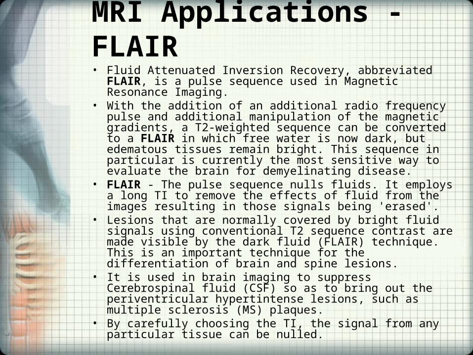
MRI Applications - FLAIR• Fluid Attenuated Inversion Recovery, abbreviated FLAIR, is a
pulse sequence used in Magnetic Resonance Imaging. • With the addition of an additional radio frequency pulse and
additional manipulation of the magnetic gradients, a T2-weighted sequence can be converted to a FLAIR in which free water is now dark, but edematous tissues remain bright. This sequence in particular is currently the most sensitive way to evaluate the brain for demyelinating disease.
• FLAIR - The pulse sequence nulls fluids. It employs a long TI to remove the effects of fluid from the images resulting in those signals being 'erased'.
• Lesions that are normally covered by bright fluid signals using conventional T2 sequence contrast are made visible by the dark fluid (FLAIR) technique. This is an important technique for the differentiation of brain and spine lesions.
• It is used in brain imaging to suppress Cerebrospinal fluid (CSF) so as to bring out the periventricular hypertintense lesions, such as multiple sclerosis (MS) plaques.
• By carefully choosing the TI, the signal from any particular tissue can be nulled.

Specialized MRI scans - Diffusion MRI • Diffusion MRI measures the diffusion of water molecules in biological
tissues. In an isotropic medium (inside a glass of water for example) water molecules naturally move randomly according to Brownian motion. In biological tissues however, the diffusion may be anisotropic. For example a molecule inside the axon of a neuron has a low probability of crossing the myelin membrane. Therefore the molecule will move principally along the axis of the neural fiber. If we know that molecules in a particular voxel diffuse principally in one direction we can make the assumption that the majority of the fibers in this area are going parallel to that direction.
• The recent development of diffusion tensor imaging (DTI) enables diffusion to be measured in multiple directions and the fractional anisotropy in each direction to be calculated for each voxel. This enables researchers to make brain maps of fiber directions to examine the connectivity of different regions in the brain (using tractography) or to examine areas of neural degeneration and demyelination in diseases like Multiple Sclerosis.

Specialized MRI scans - Diffusion Weighted Imaging
• Another application of diffusion MRI is diffusion-weighted imaging (DWI). Following an ischemic stroke, DWI is highly sensitive to the changes occurring in the lesion. It is speculated that increases in restriction (barriers) to water diffusion, as a result of cytotoxic edema (cellular swelling), is responsible for the increase in signal on a DWI scan. The DWI enhancement appears within 5-10 minutes of the onset of stroke symptoms (as compared with computed tomography, which often does not detect changes of acute infarct for up to 4-6 hours) and remains for up to two weeks. Coupled with imaging of cerebral perfusion, researchers can highlight regions of "perfusion/diffusion mismatch" that may indicate regions capable of salvage by reperfusion therapy.
• Like many other specialized applications, this technique is usually coupled with a fast image acquisition sequence.
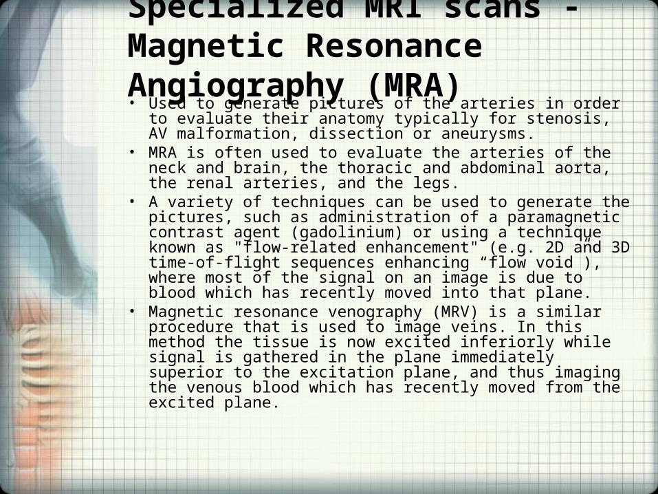
Specialized MRI scans - Magnetic Resonance Angiography (MRA)• Used to generate pictures of the arteries in order to evaluate their
anatomy typically for stenosis, AV malformation, dissection or aneurysms.
• MRA is often used to evaluate the arteries of the neck and brain, the thoracic and abdominal aorta, the renal arteries, and the legs.
• A variety of techniques can be used to generate the pictures, such as administration of a paramagnetic contrast agent (gadolinium) or using a technique known as "flow-related enhancement" (e.g. 2D and 3D time-of-flight sequences enhancing “flow void”), where most of the signal on an image is due to blood which has recently moved into that plane.
• Magnetic resonance venography (MRV) is a similar procedure that is used to image veins. In this method the tissue is now excited inferiorly while signal is gathered in the plane immediately superior to the excitation plane, and thus imaging the venous blood which has recently moved from the excited plane.
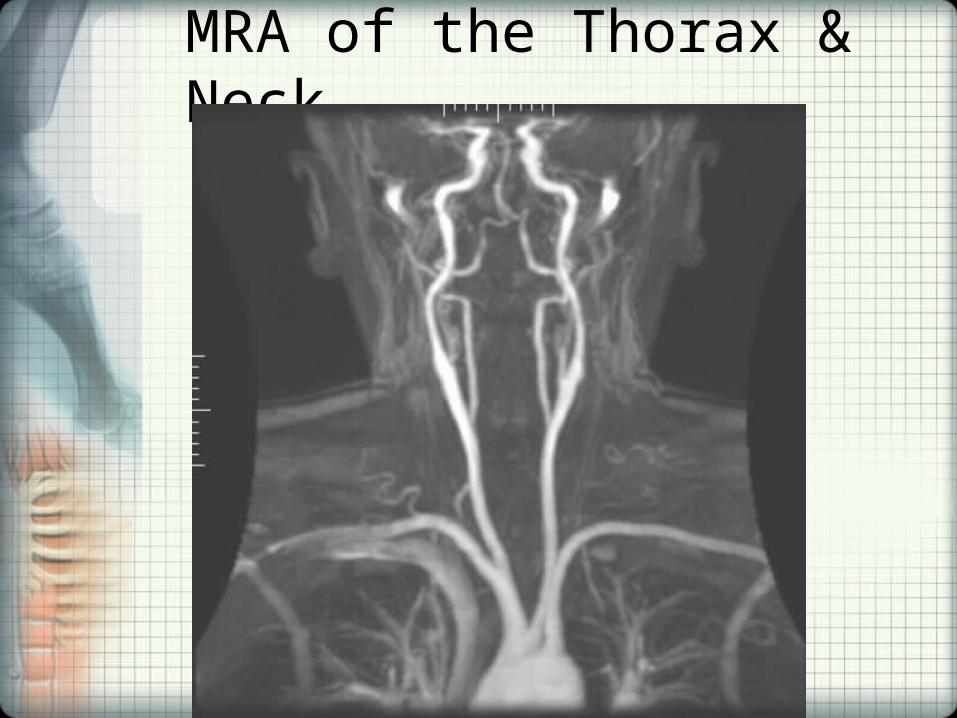
MRA of the Thorax & Neck
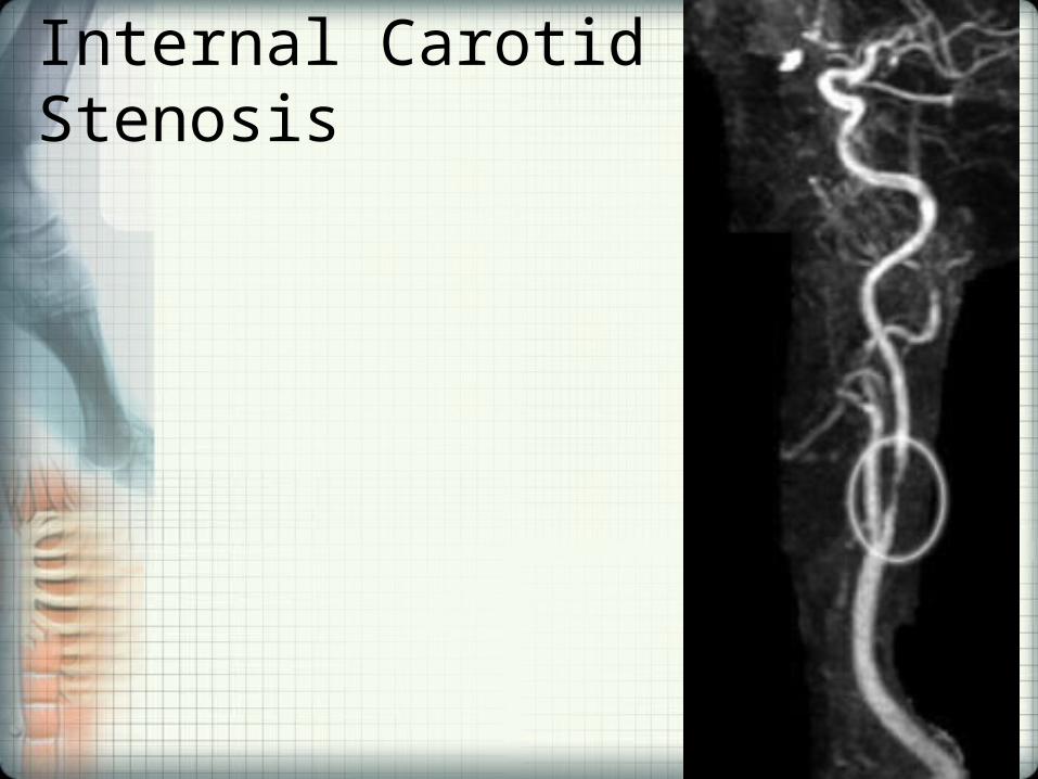
Internal Carotid Stenosis
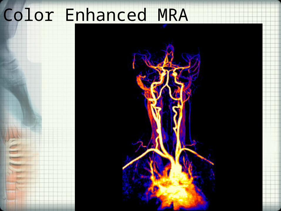
Color Enhanced MRA
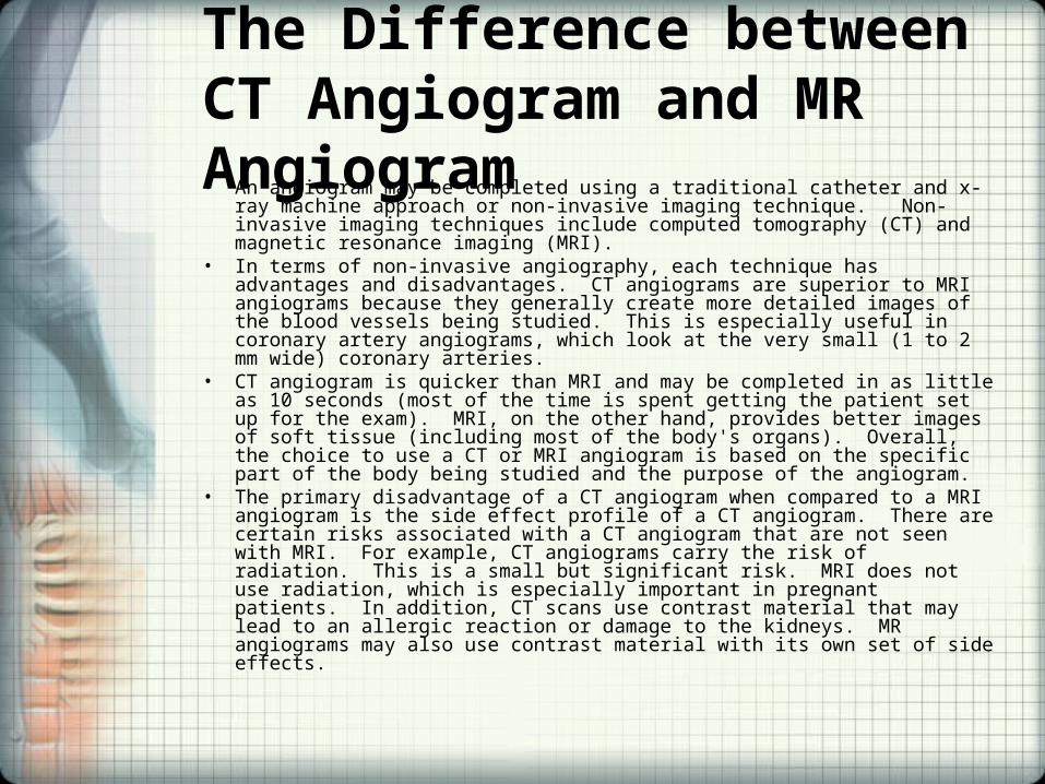
The Difference between CT Angiogram and MR Angiogram• An angiogram may be completed using a traditional catheter and x-ray machine
approach or non-invasive imaging technique. Non-invasive imaging techniques include computed tomography (CT) and magnetic resonance imaging (MRI).
• In terms of non-invasive angiography, each technique has advantages and disadvantages. CT angiograms are superior to MRI angiograms because they generally create more detailed images of the blood vessels being studied. This is especially useful in coronary artery angiograms, which look at the very small (1 to 2 mm wide) coronary arteries.
• CT angiogram is quicker than MRI and may be completed in as little as 10 seconds (most of the time is spent getting the patient set up for the exam). MRI, on the other hand, provides better images of soft tissue (including most of the body's organs). Overall, the choice to use a CT or MRI angiogram is based on the specific part of the body being studied and the purpose of the angiogram.
• The primary disadvantage of a CT angiogram when compared to a MRI angiogram is the side effect profile of a CT angiogram. There are certain risks associated with a CT angiogram that are not seen with MRI. For example, CT angiograms carry the risk of radiation. This is a small but significant risk. MRI does not use radiation, which is especially important in pregnant patients. In addition, CT scans use contrast material that may lead to an allergic reaction or damage to the kidneys. MR angiograms may also use contrast material with its own set of side effects.
Specialized MRI Scans - Magnetic Resonance Spectroscopy
• Used to measure the levels of different metabolites in body tissues. The MR signal produces a spectrum of resonances that correspond to different molecular arrangements of the isotope being "excited". This signature is used to diagnose certain metabolic disorders, especially those affecting the brain, as well as to provide information on tumor metabolism.
• Magnetic resonance spectroscopic imaging (MRSI) combines both spectroscopic and imaging methods to produce spatially localized spectra from within the sample or patient.
• The spatial resolution is much lower, but the spectra in each voxel contains information about many metabolites. Because the available signal is used to encode spatial and spectral information, MRSI requires high field strengths (1.5T+)
Specialized MRI scans - Functional MRI (fMRI)• Measures signal changes in the brain that are due to changing neural activity. • The brain is scanned at low resolution but at a rapid rate (typically once every 2-
3 seconds). • Increases in neural activity cause changes in the MR signal via T2* changes; this
mechanism is referred to as the BOLD (blood-oxygen-level dependent) effect. • Increased neural activity causes an increased demand for oxygen, and the
vascular system actually overcompensates for this, increasing the amount of oxygenated hemoglobin relative to deoxygenated hemoglobin. Because deoxygenated hemoglobin attenuates the MR signal, the vascular response leads to a signal increase that is related to the neural activity. The precise nature of the relationship between neural activity and the BOLD signal is a subject of current research. The BOLD effect also allows for the generation of high resolution 3D maps of the venous vasculature within neural tissue.
• While BOLD signal is the most common method employed for neuroscience studies in human subjects, the flexible nature of MR imaging provides means to sensitize the signal to other aspects of the blood supply.
• Alternative techniques employ arterial spin labeling (ASL) or weight the MRI signal by cerebral blood flow (CBF) and cerebral blood volume (CBV). The CBV method requires injection of a class of MRI contrast agents that are now in human clinical trials. This method has been shown to be far more sensitive than the BOLD technique in preclinical studies.
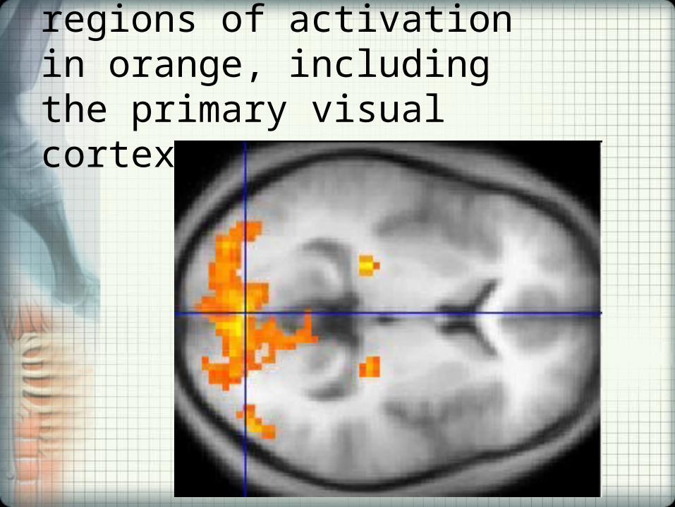
A fMRI scan showing regions of activation in orange, including the primary visual cortex
Specialized MRI scans• Interventional MRI - The lack of harmful effects on the
patient and the operator make MRI well-suited for "interventional radiology", where the images produced by a MRI scanner are used to guide minimally-invasive procedures. Of course, such procedures must be done without any ferromagnetic instruments.– A specialized growing subset of interventional MRI is that of
intraoperative MRI in which the MRI is used in the surgical process. Some specialized MRI systems have been developed that allow imaging concurrent with the surgical procedure. More typical, however, is that the surgical procedure is temporarily interrupted so that MR images can be acquired to verify the success of the procedure or guide subsequent surgical work.
• Radiation therapy simulation - Because of MRI's superior imaging of soft tissues, it is now being utilized to specifically locate tumors within the body in preparation for radiation therapy treatments. For therapy simulation, a patient is placed in specific, reproducible, body position and scanned. The MRI system then computes the precise location, shape and orientation of the tumor mass, correcting for any spatial distortion inherent in the system. The patient is then marked or tattooed with points which, when combined with the specific body position, will permit precise triangulation for radiation therapy.
Specialized MRI scans• Current density imaging - Current density imaging (CDI) endeavors
to use the phase information from images to reconstruct current densities within a subject. Current density imaging works because electrical currents generate magnetic fields, which in turn affect the phase of the magnetic dipoles during an imaging sequence. To date no successful CDI has been performed using biological currents, but several studies have been published which involve applied currents through a pair of electrodes.
• Magnetic resonance guided focused ultrasound - In MRgFUS therapy, ultrasound beams are focused on a tissue - guided and controlled using MR thermal imaging - and due to the significant energy deposition at the focus, temperature within the tissue rises to more than 65°C, completely destroying it. This technology can achieve precise "ablation" of diseased tissue. MR imaging provides a three-dimensional view of the target tissue, allowing for precise focusing of ultrasound energy. The MR imaging provides quantitative, real-time, thermal images of the treated area. This allows the physician to ensure that the temperature generated during each cycle of ultrasound energy is sufficient to cause thermal ablation within the desired tissue and if not, to adapt the parameters to ensure effective treatment.
Specialized MRI scans• Multinuclear imaging - Hydrogen is the most frequently imaged nucleus in MRI
because it is present in biological tissues in great abundance. However, any nucleus which has a net nuclear spin could potentially be imaged with MRI. Such nuclei include helium-3, carbon-13, fluorine-19, oxygen-17, sodium-23, phosphorus-31 and xenon-129. 23Na and 31P are naturally abundant in the body, so can be imaged directly. Gaseous isotopes such as ³He or 129Xe must be hyperpolarized and then inhaled as their nuclear density is too low to yield a useful signal under normal conditions. 17O, 13C and 19F can be administered in sufficient quantities in liquid form. Multinuclear imaging is primarily a research technique at present. However, potential applications include functional imaging and imaging of organs poorly seen on 1H MRI (e.g. lungs and bones) or as alternative contrast agents. Inhaled hyperpolarized ³He can be used to image the distribution of air spaces within the lungs. Injectable solutions containing 13C or stabilized bubbles of hyperpolarized 129Xe have been studied as contrast agents for angiography and perfusion imaging. 31P can potentially provide information on bone density and structure, as well as functional imaging of the brain.
• Susceptibility weighted imaging (SWI) - Susceptibility weighted imaging (SWI), is a new type of contrast in MRI different from spin density, T1, or T2 imaging. This method exploits the susceptibility differences between tissues and uses a fully velocity compensated, three dimensional, rf spoiled, high-resolution, 3D gradient echo scan. This special data acquisition and image processing produces an enhanced contrast magnitude image very sensitive to venous blood, hemorrhage and iron storage. It is used to enhance the detection and diagnosis of tumors, vascular and neurovascular diseases (stroke and hemorrhage, multiple sclerosis, Alzheimer's), and also detects traumatic brain injuries that may not be diagnosed using other methods.
Specialized MRI scans• Other specialized MRI techniques - MRI is a new and active
field of research and new methods and variants are often published when they are able to get better results in specific fields. Examples of these recent improvements are T2-weighted (T2 TSE MRI), MRI (DIR-MRI) or MRI (PSIR-MRI), all of them able to improve imaging of the brain lesions.
• Portable instruments - Portable magnetic resonance instruments are available for use in education and field research. Using the principles of Earth's field NMR, they have no powerful polarizing magnet, so that such instruments can be small and relatively inexpensive. Some can be used for both EFNMR spectroscopy and MRI imaging. The low strength of the Earth's field results in poor signal to noise ratios, requiring relatively long scan times to capture spectroscopic data or build up MRI images.

MRI versus CT• A computed tomography (CT) scanner uses X-rays, a type of ionizing radiation, to
acquire its images, making it a good tool for examining tissue composed of elements of a higher atomic number than the tissue surrounding them, such as bone and calcifications within the body. MRI, on the other hand, uses non-ionizing radio frequency (RF) signals to acquire its images and is best suited for non-calcified tissue, though MR images can also be acquired from bones and teeth as well as fossils.
• CT may be enhanced by use of contrast agents containing elements of a higher atomic number than the surrounding flesh such as iodine or barium. Contrast agents for MRI are those which have paramagnetic properties, e.g. gadolinium and manganese.
• Both CT and MRI scanners can generate multiple two-dimensional cross-sections (slices) of tissue and three-dimensional reconstructions. Unlike CT, which uses only X-ray attenuation to generate image contrast, MRI has a long list of properties that may be used to generate image contrast. By variation of scanning parameters, tissue contrast can be altered and enhanced in various ways to detect different features.
• MRI can generate cross-sectional images in any plane (including oblique planes). In the past, CT was limited to acquiring images in the axial (or near axial) plane. The scans used to be called Computed Axial Tomography scans (CAT scans). However, the development of multi-detector CT scanners with near-isotropic resolution, allows the CT scanner to produce data that can be retrospectively reconstructed in any plane with minimal loss of image quality.
• For purposes of tumor detection and identification in the brain, MRI is generally superior. However, in the case of solid tumors of the abdomen and chest, CT is often preferred due to less motion artifact. Furthermore, CT usually is more widely available, faster, much less expensive, and may be less likely to require the person to be sedated or anesthetized.
CASES IN CHIROPRACTIC NEUROLOGY• Case 154
• Case 167

Ultrasound
• Cyclic sound pressure with a frequency greater than the upper limit of human hearing.
• The production of ultrasound is used for diagnostic and therapeutic purposes, typically to penetrate a medium and measure the reflection signature (echo – diagnostic) or supply focused energy (therapeutic).
• The reflection signature can reveal details about the inner structure of the medium.
General Ultrasound Imaging• Ultrasound imaging, also called ultrasound scanning
or sonography, involves exposing part of the body to high-frequency sound waves and do not use ionizing radiation.
• Because ultrasound images are captured in real-time, they can show the structure and movement of the body's internal organs, as well as blood flowing through blood vessels.
• Ultrasound imaging is painless.• Conventional ultrasound displays the images in thin,
flat sections of the body. Advancements in ultrasound technology include three-dimensional (3-D) ultrasound that formats the sound wave data into 3-D images. Four-dimensional (4-D) ultrasound is 3-D ultrasound in motion.
Doppler Ultrasound• Doppler ultrasound is a special ultrasound technique that
evaluates blood as it flows through a blood vessel, including the body's major arteries and veins in the abdomen, arms, legs and neck.
• There are several types of Doppler ultrasound: • “Bedside” or continuous wave Doppler. This type uses the
change in pitch of the sound waves to provide information about blood flow through a blood vessel. The doctor listens to the sounds produced by the transducer to evaluate the blood flow through an area that may be blocked or narrowed. This type of ultrasound can be done at the bedside in the hospital with a portable machine to provide a rapid estimate of the extent of blood vessel damage or disease.
• Duplex Doppler. Duplex Doppler ultrasound uses standard ultrasound methods to produce a picture of a blood vessel and the surrounding organs. In addition, a computer converts the Doppler sounds into a graph that provides information about the speed and direction of blood flow through the blood vessel being evaluated in terms of the distance traveled per unit of time
Doppler Ultrasound• Color Doppler. Color Doppler uses standard ultrasound
methods to produce a picture of a blood vessel. In addition, a computer converts the Doppler sounds into colors that are overlaid on the image of the blood vessel and that represent the speed and direction of blood flow through the vessel.
• Power Doppler. Power Doppler is a newer ultrasound technique that is up to 5 times more sensitive in detecting blood flow than color Doppler. Power Doppler can obtain some images that are difficult or impossible to obtain using standard color Doppler. However, power Doppler is most commonly used to evaluate blood flow through vessels within solid organs.
• Blood flow in individual blood vessels is most commonly evaluated by combining color Doppler with duplex Doppler. Together, they are able to provide better information on the direction and speed of blood flow than when these techniques are used individually.
US - Common Uses - Imaging• Stenosis of heart and blood vessels, including the abdominal aorta and
its major branches • Liver • Gallbladder • Spleen • Pancreas • Kidneys • Bladder • Uterus, ovaries, and unborn child (fetus) in pregnant patients • Eyes • Thyroid and parathyroid glands • Scrotum (testicles) • Ultrasound is also used to guide procedures such as needle biopsies, in
which needles are used to extract sample cells from an abnormal area for laboratory testing.
• Image the breasts and to guide biopsy of breast cancer.
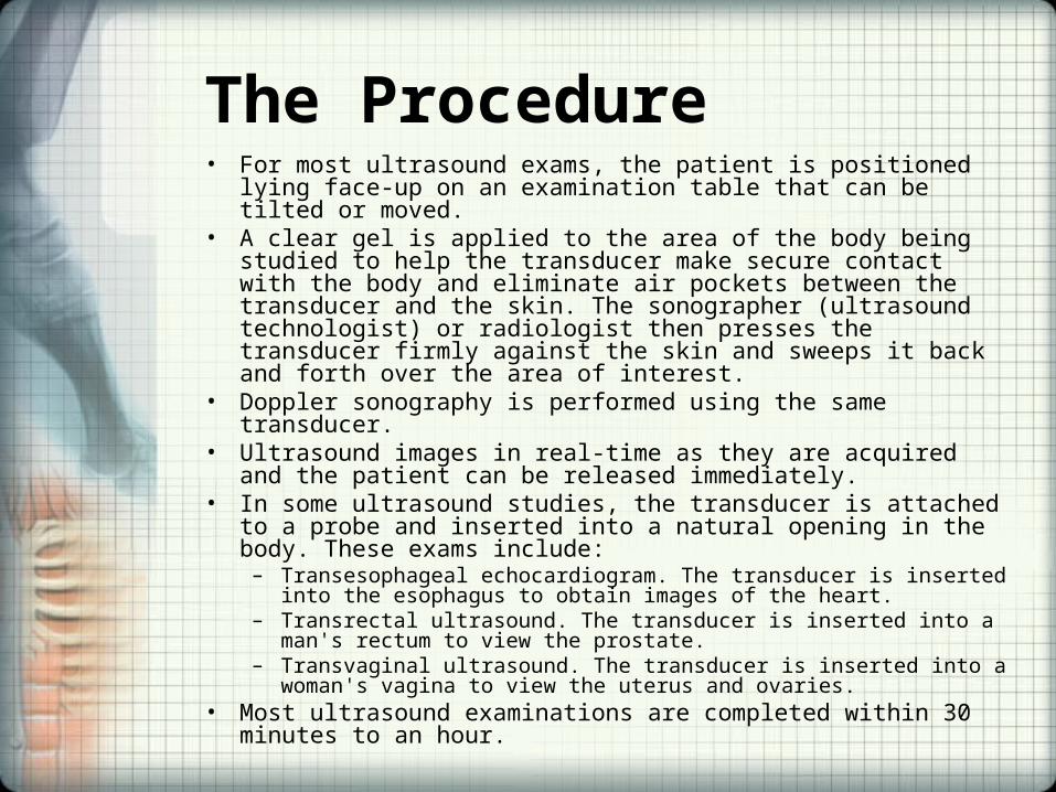
The Procedure• For most ultrasound exams, the patient is positioned lying face-up on an
examination table that can be tilted or moved.• A clear gel is applied to the area of the body being studied to help the
transducer make secure contact with the body and eliminate air pockets between the transducer and the skin. The sonographer (ultrasound technologist) or radiologist then presses the transducer firmly against the skin and sweeps it back and forth over the area of interest.
• Doppler sonography is performed using the same transducer.• Ultrasound images in real-time as they are acquired and the patient can
be released immediately.• In some ultrasound studies, the transducer is attached to a probe and
inserted into a natural opening in the body. These exams include:– Transesophageal echocardiogram. The transducer is inserted into the
esophagus to obtain images of the heart. – Transrectal ultrasound. The transducer is inserted into a man's rectum to
view the prostate. – Transvaginal ultrasound. The transducer is inserted into a woman's vagina to
view the uterus and ovaries. • Most ultrasound examinations are completed within 30 minutes to an
hour.

US Equipment
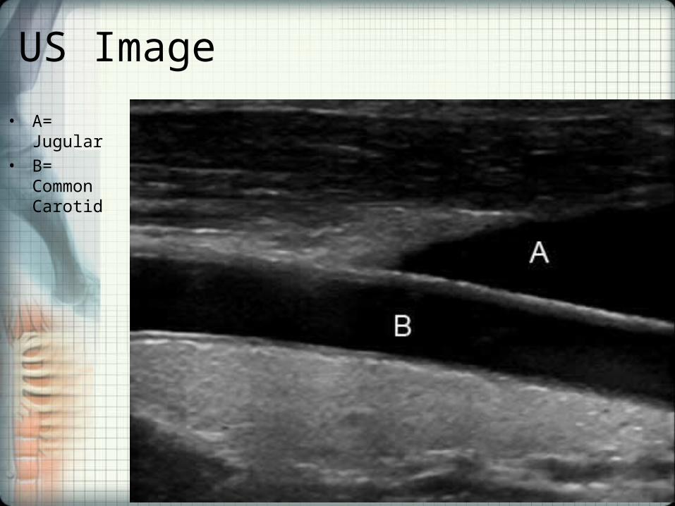
US Image
• A= Jugular
• B= Common Carotid
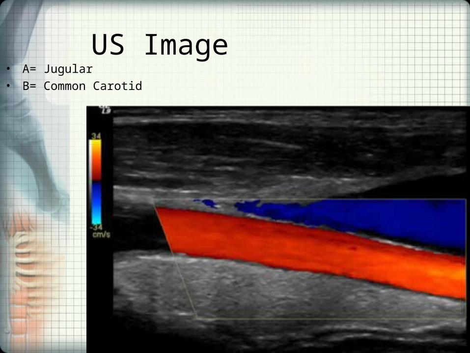
US Image• A= Jugular
• B= Common Carotid

Limitations of Ultrasound Imaging• Ultrasound waves do not pass through air;
therefore an evaluation of the lung, stomach, small intestine and large intestine may be limited.
• Intestinal gas may also prevent visualization of deeper structures such as the pancreas and aorta.
• Patients who are obese are more difficult to image because tissue attenuates the sound waves as they pass deeper into the body.
• Ultrasound has difficulty penetrating bone and therefore can only see the outer surface of bony structures and not what lies within.
Transcranial Doppler (TCD)
• A test that measures the velocity of blood flow through the brain's blood vessels.
• Used to help in the diagnosis of emboli, stenosis, vasospasm, hemorrhage, dissection, tumors, etc.
• Relatively quick and inexpensive test is growing in popularity.
• The equipment used for these tests is becoming increasingly portable.
Methods
• Two methods of recording may be used for this procedure. – The first uses "B-mode" imaging, which displays a
2-dimensional image as seen by the ultrasound probe. Once the desired blood vessel is found, blood flow velocities may be measured with a pulsed doppler probe, which graphs velocities over time. Together, these make a duplex test.
– The second method of recording uses only the second probe function, relying instead on the training and experience of the clinician in finding the correct vessels.
Applications of TCD
• Clinical routine transcranial Doppler (TCD) ultrasound examination of the intracranial arteries was demonstrated to be possible in 1982.
• The value obtained for a particular artery is the velocity of blood flowing through the vessel, and unless the diameter of that vessel is established by some other means it is not possible to determine the actual blood flow.
• Thus TCD is primarily a technique for measuring relative changes in flow.
Transcranial USD Physics• Blood flow velocity is recorded by emitting a sound
wave from the ultrasound probe, which then bounces off (echo) of various materials to be measured by the same probe. Normally a range of depths and angles must be measured to ascertain the correct velocities, as recording from an angle to the blood vessel yields an artificially low velocity.
• Because the bones of the skull block the transmission of ultrasound, regions with thinner walls - insonation windows - must be used for analyzing.
• For this reason, recording is performed in the temporal region above the cheekbone/zygomatic arch, through the eyes, below the jaw, and from the back of the head. Patient age, gender, race and other factors affect bone thickness, making some examinations more difficult or even impossible.

Functional Transcranial Doppler (fTCD)• A neuroimaging tool for measuring cerebral blood flow velocity
changes due to neural activation during cognitive tasks. • Functional TCD utilizes pulse-wave Doppler technology to record blood
flow velocities in the anterior, middle, and posterior cerebral arteries. • Similar to other neuroimaging techniques such as functional magnetic
resonance imaging or positron emission tomography, fTCD is based on a close coupling between regional cerebral blood flow changes and neural activation.
• Unlike PET and fMRI, it is a continuous, real time, monitoring of blood flow velocity undegraded by movement artifacts.
• The technique is noninvasive and easy to apply. Since its introduction the technique has contributed substantially to the elucidation of the hemispheric organization of cognitive, motor, and sensory functions in adults and children.
• fTCD has been particularly been useful for the study of cerebral lateralization of major brain functions such as language, facial processing, color processing, intelligence processing and gender-related differences.
• Moreover, most established neuroanatomical substrates for brain function are perfused by the major cerebral arteries that could be directly insonated.
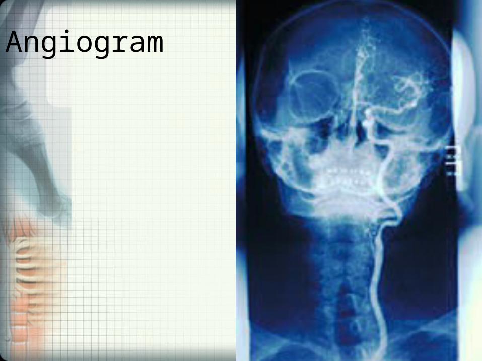
Angiography• An arteriogram is an x-ray of the heart chambers and/or arteries
typically looking for aneurysm, stenosis, malformation, dissection, occlusions or for characterization of masses.
• Its name comes from the Greek words angeion, "vessel", and graphein, "to write or record".
• Other names for this procedure are angiogram and arteriography.• During an arteriogram, a dye is injected into an artery making the
arteries visible on x-ray. Many arteries can be examined by an arteriogram, including the arterial systems of the legs, kidneys, brain, and heart.
• Rapidly being replaced by CT or MR Angiography due to high morbidity and mortality (1:100) of the procedure.
• Fluoroscopy is often used during an arteriogram. Fluoroscopy is a study of moving body structures - similar to an x-ray “movie.” A continuous x-ray beam is passed through the body part being examined, and is transmitted to a TV-like monitor so that the body part and its motion can be seen in detail.
• Arteriogram may be performed in conjunction with CT, MRI, or ultrasound, which provides greater detail.
Angiogram
Arteriovenous Malformation (AVM’s)
• An arteriovenous malformation (AVM) is an abnormal collection of blood vessels that may occur in the brain or spinal cord.
• In an AVM, there is a short circuit and blood travels rapidly from the arteries directly into the veins. Pressure can build up causing bleeding from the AVM or the veins, which do not have enough support in their walls.
• AVM’s are graded by size, type of venous drainage and whether they involve eloquent tissue such as speech or motor cortex (Spetzler-Martin Classification).
• On average, there is a 1% per year likelihood of intracranial bleeding.
• Patients can be asymptomatic or may present with headaches, seizures, or deterioration of neurological function.
• If intracranial hemorrhage occurs patients may experience severe headache, stroke-like symptoms or even loss of consciousness. In the cord hemorrhage causes bilateral rib or girdle pain, quad or paraplegia, sensory loss with a clear level.
Arteriovenous Malformation (AVM’s)• Treatment of AVM’s may include surgical excision, radiation treatment
or embolization. In many cases, embolization is used to block supply to the AVM and make definitive treatment safe. This may include reduction in size of the AVM, closure of large fistulas, and treatment of aneurysms, which are associated with the AVM nidus or arterial feeders.
• Embolization is performed under general anesthesia. A sheath and catheter system is placed in the femoral artery, usually in the right groin. The catheter system is brought up to the neck and diagnostic angiogram is obtained. Using this information and live fluoroscopic visualization, a microcatheter is placed through the guide catheter and navigated into the arteries supplying the AVM. Another angiogram is done to determine whether it is a safe artery to block off. If so, then liquid embolic agent is used such as ONYX or N-butyl cyanoacrolate in a mixture with radio-opaque material. This process is repeated up to several times after which the catheters are removed and the arteriotomy site is closed.
• Blood flow to the AVM may be treated in stages to prevent thrombosis or hemorrhage from occurring. In some cases, embolization may fully treat a lesion, but most patients will undergo surgical resection or radiation therapy. Angiography is used following these treatments to insure the lesion is fully treated.
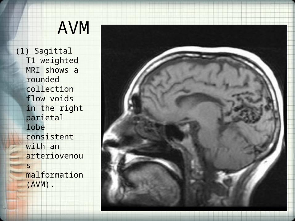
AVM(1) Sagittal T1
weighted MRI shows a rounded collection flow voids in the right parietal lobe consistent with an arteriovenous malformation (AVM).
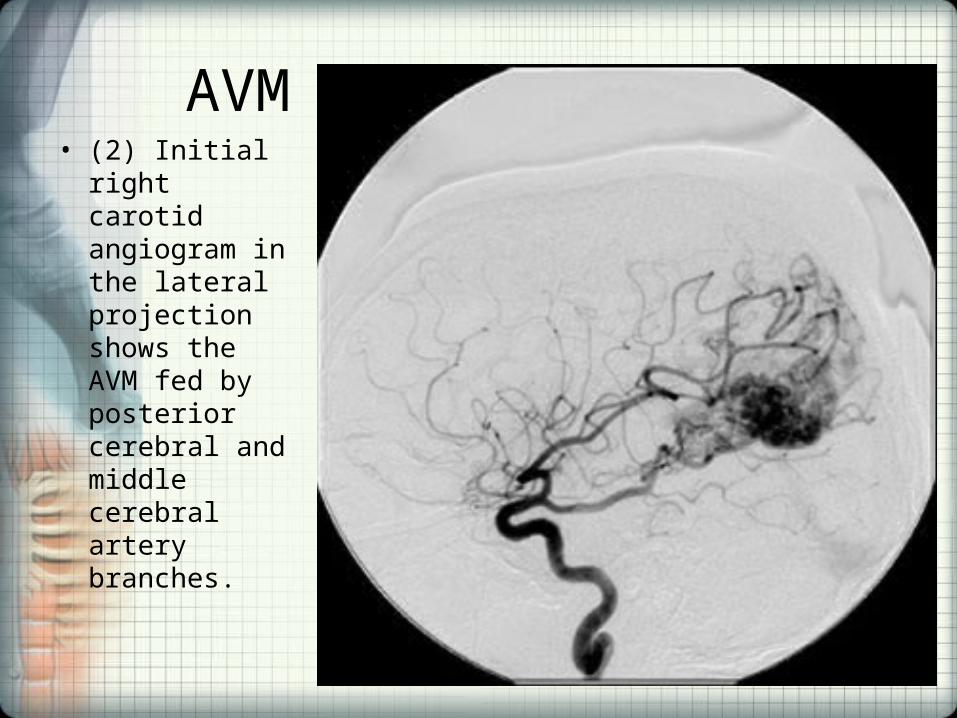
AVM• (2) Initial right
carotid angiogram in the lateral projection shows the AVM fed by posterior cerebral and middle cerebral artery branches.
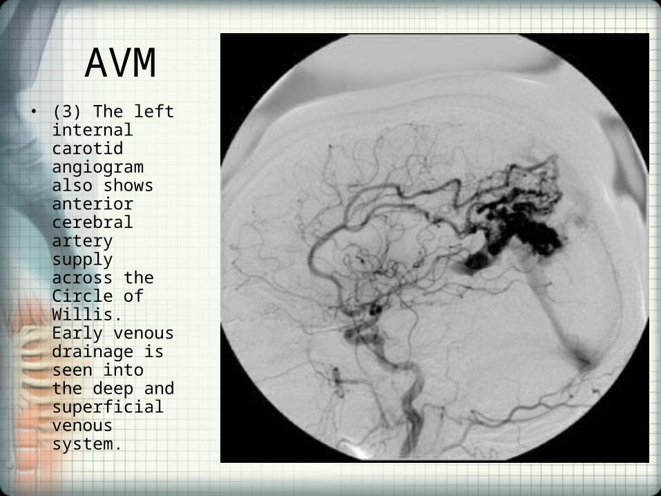
AVM• (3) The left
internal carotid angiogram also shows anterior cerebral artery supply across the Circle of Willis. Early venous drainage is seen into the deep and superficial venous system.

AVM• (4,5,6) Post
embolization angiograms of the right and left internal carotid arteries show marked reduction in the size and flow of the AVM.
AVM
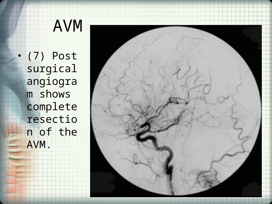
• (7) Post surgical angiogram shows complete resection of the AVM.
PET Scan• Nuclear medicine procedures use radiopharmaceuticals or
radiotracers, which are injected into the bloodstream, swallowed or inhaled as a gas.
• This radioactive material accumulates in the organ or area of the body being examined, where it gives off a small amount of energy in the form of gamma rays. A gamma camera, PET scanner, or probe detects this energy and with the help of a computer creates pictures offering details on both the structure and function of organs and tissues in your body.
• Unlike other imaging techniques, nuclear medicine imaging studies are less directed toward picturing anatomy and structure, and more concerned with depicting physiologic processes within the body, such as rates of metabolism or levels of various other chemical activity.
• Areas of greater intensity, called "hot spots", indicate where large amounts of the radiotracer have accumulated and where there is a high level of chemical activity.
• Less intense areas, or "cold spots", indicate a smaller concentration of radiotracer and less chemical activity.

Positron Emission Tomography (PET) Scan• Depending on the type of nuclear medicine
exam, the radiotracer (Radionuclides used in PET scanning are typically isotopes with short half lives such as carbon-11 (~20 min), nitrogen-13 (~10 min), oxygen-15 (~2 min), and fluorine-18 (~110 min) is either injected into a vein, swallowed or inhaled as a gas and eventually accumulates in the organ or area of your body being examined, where after undergoing “positron/electron annialation” it gives off energy in the form of gamma rays. This energy is detected by a gamma camera.
Positron Emission Tomography Computed Tomography (PET/CT) Scan• Nuclear medicine images can be superimposed with
computed tomography (CT) or magnetic resonance imaging (MRI) to produce special views, a practice known as image fusion or co-registration. These views allow the information from two different studies to be correlated and interpreted on one image, leading to more precise
• Most modern PET scans are performed on instruments that are combined PET and CT scanners. The combined PET/CT scans provide images that pinpoint the location of abnormal metabolic activity within the body. The combined scans have been shown to provide more accurate diagnoses than the two scans performed separately.
Typical uses of the procedure
• Evaluate brain abnormalities, such as tumors, memory disorders, movement disorders, seizures and a wide variety of central nervous system disorders.
• Detect cancer • Determine whether a cancer has spread in the body • Assess the effectiveness of a treatment plan, such as
cancer therapy • Determine if a cancer has returned after treatment • Determine blood flow to the heart muscle • Determine the effects of a heart attack, or myocardial
infarction, on areas of the heart.• To map normal human brain and heart function
Specific Application to Neurology• PET neuroimaging is based on an assumption that areas
of high radioactivity are associated with brain activity. What is actually measured indirectly is the flow of blood to different parts of the brain, which is generally believed to be correlated, and has been measured using the tracer oxygen-15.
• However, because of its 2-minute half-life O-15 must be piped directly from a medical cyclotron for such uses, and this is difficult. In practice, since the brain is normally a rapid user of glucose, and since brain pathologies such as Alzheimer's disease greatly decrease brain metabolism of both glucose and oxygen in tandem, standard FDG -PET (fluorine-18 (F-18) fluorodeoxyglucose), is widely used in clinical neurology. This tracer is a glucose analog that is taken up by glucose-using cells
• The PET of the brain, then measures regional glucose use, may also be successfully used to differentiate Alzheimer's disease from other dementias, and also to make early diagnosis of Alzheimer's disease.
Specific Application to Neurology
• The advantage of FDG-PET for these uses is its much wider availability. PET imaging with FDG can also be used for localization of seizure focus: A seizure focus will appear as hypometabolic during an interictal scan.
• Several radiotracers (i.e. radioligands) have been developed for PET that are ligands for specific neuroreceptor subtypes.
• These agents permit the visualization of neuroreceptor pools in the context of a plurality of neuropsychiatric and neurologic illnesses. A novel probe developed at the University of Pittsburgh termed PIB (Pittsburgh Compound-B) permits the visualization of amyloid plaques in the brains of Alzheimer's patients.

PET Scanner

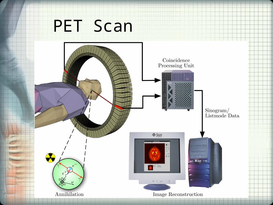
Positron emission tomography (PET)• Produces a three-dimensional image or map of
functional processes in the body. The system detects pairs of gamma rays emitted indirectly by a positron-emitting radionuclide (tracer), which is introduced into the body on a biologically active molecule.
• Images of tracer concentration in 3-dimensional space within the body are then reconstructed by computer analysis.
• Although FDG tracer is the most common type of PET scan, other tracer molecules are used in PET to image the tissue concentration of many other types of molecules of interest.
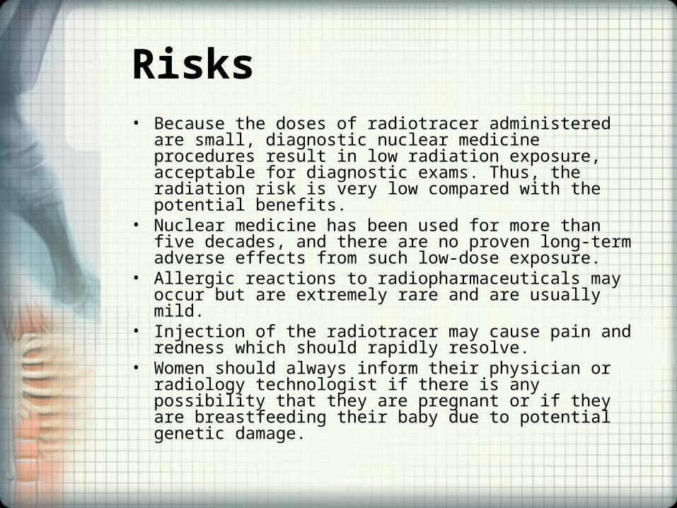
Risks• Because the doses of radiotracer administered are small,
diagnostic nuclear medicine procedures result in low radiation exposure, acceptable for diagnostic exams. Thus, the radiation risk is very low compared with the potential benefits.
• Nuclear medicine has been used for more than five decades, and there are no proven long-term adverse effects from such low-dose exposure.
• Allergic reactions to radiopharmaceuticals may occur but are extremely rare and are usually mild.
• Injection of the radiotracer may cause pain and redness which should rapidly resolve.
• Women should always inform their physician or radiology technologist if there is any possibility that they are pregnant or if they are breastfeeding their baby due to potential genetic damage.
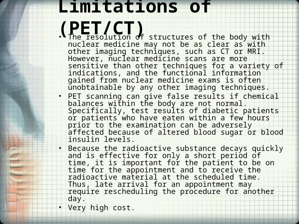
Limitations of (PET/CT)• The resolution of structures of the body with nuclear medicine
may not be as clear as with other imaging techniques, such as CT or MRI. However, nuclear medicine scans are more sensitive than other techniques for a variety of indications, and the functional information gained from nuclear medicine exams is often unobtainable by any other imaging techniques.
• PET scanning can give false results if chemical balances within the body are not normal. Specifically, test results of diabetic patients or patients who have eaten within a few hours prior to the examination can be adversely affected because of altered blood sugar or blood insulin levels.
• Because the radioactive substance decays quickly and is effective for only a short period of time, it is important for the patient to be on time for the appointment and to receive the radioactive material at the scheduled time. Thus, late arrival for an appointment may require rescheduling the procedure for another day.
• Very high cost.
PET Scan

SPECT Scan• A Single Photon Emission Computed Tomography
(SPECT) scan is a type of nuclear imaging test that shows how blood flows to tissues and organs.
• The test differs from a PET scan in that the chemical tracer (radioisotopes typically used in SPECT are iodine-123, technetium-99m, xenon-133, thallium-201, and fluorine-18) stays in your blood stream rather than being absorbed by surrounding tissues, thereby limiting the images to areas where blood flows.
• SPECT scans are cheaper and more readily available than higher resolution PET scans.
SPECT Scan• A SPECT scan is primarily used to view how blood
flows through arteries and veins in the brain. Tests have shown that it might be more sensitive to brain injury than either MRI or CT scanning because it can detect reduced blood flow to injured sites.
• Also useful in diagnosing:– Stress fractures in the spine (spondylolysis)
– Blood deprived (ischemic) areas of brain following stroke
– Tumors
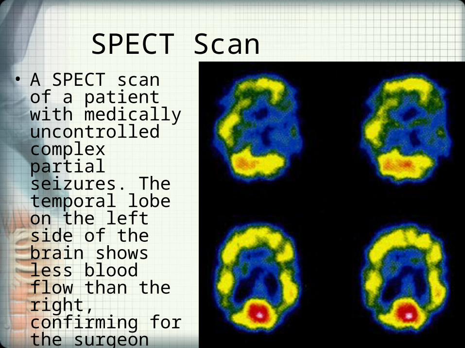
SPECT Scan• A SPECT scan of a
patient with medically uncontrolled complex partial seizures. The temporal lobe on the left side of the brain shows less blood flow than the right, confirming for the surgeon the nonfunctioning area of the brain causing seizures.
Bone Scan• A bone scan is a nuclear scanning test that identifies new areas of bone
growth or breakdown. • It can be done to evaluate damage to the bones, detect cancer that has
metastasized to the bones, and monitor conditions that can affect the bones (including infection and trauma).
• A bone scan can often detect a problem days to months earlier than a regular X-ray test.
• For a bone scan, a radioactive tracer substance is injected into a vein in the arm. The tracer then travels through the bloodstream and into the bones.
• A gamma camera takes pictures of the tracer in the bones. This helps show cell activity and function in the bones. Areas that absorb little or no amount of tracer appear as dark or "cold" spots, which may indicate a lack of blood supply to the bone (bone infarction) or the presence of certain types of cancer.
• Areas of rapid bone growth or repair absorb increased amounts of the tracer and show up as bright or "hot" spots in the pictures. Hot spots may indicate the presence of a tumor, arthritis, fracture, or an infection.
• A bone scan may be done on the entire body or just a part of it.
Bone Scan May• Determine whether a cancer from another area, such
as the breast, lung, kidney, thyroid gland, or prostate gland, has metastasized to the bone.
• Help diagnose the cause or location of unexplained bone pain, such as ongoing low back pain.
• A bone scan may be done initially to help determine the location of an abnormal bone in complex bone structures such as the foot or spine.
• Help diagnose broken bones, such as a hip fracture or a stress fracture, not clearly seen on X-ray.
• Detect damage to the bones caused by infection or other conditions, such as Paget's disease.
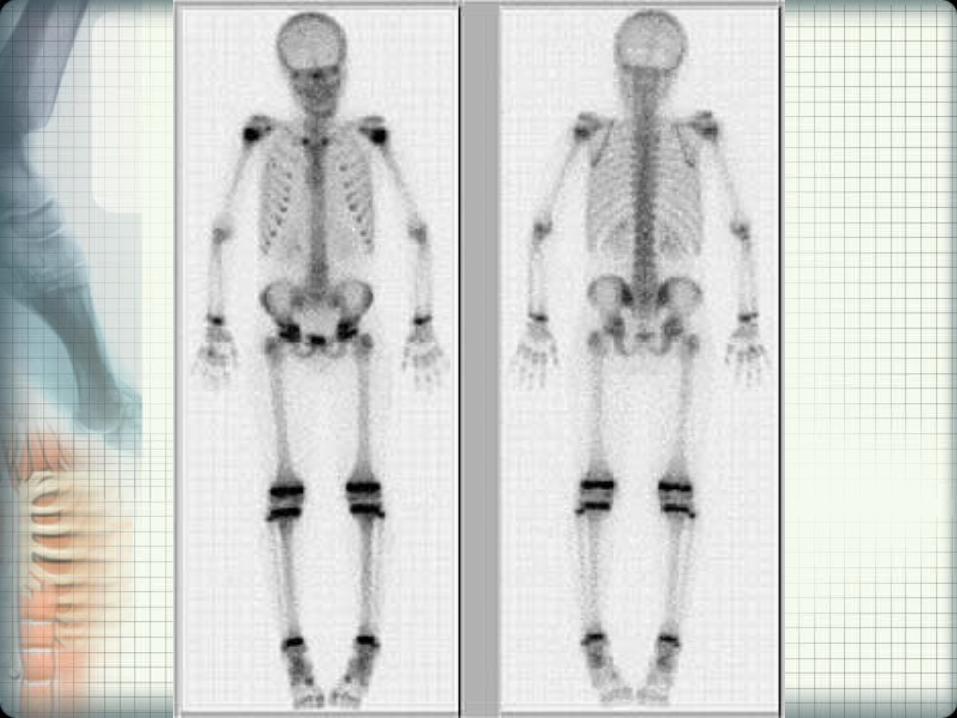

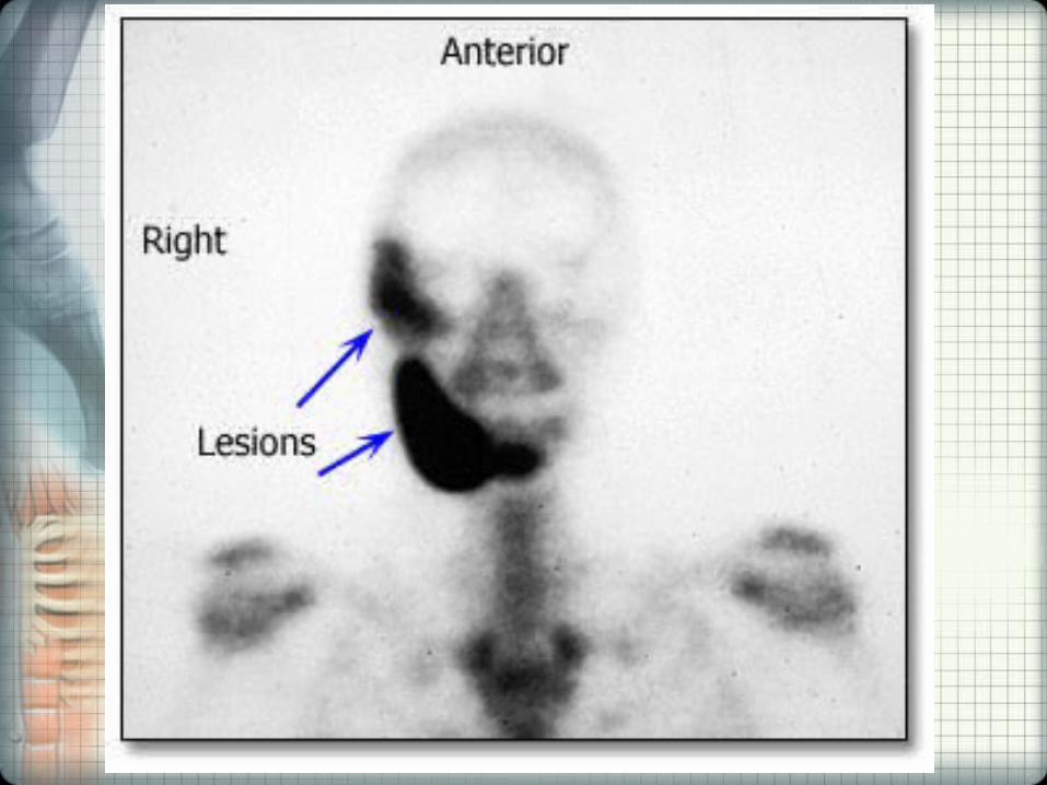
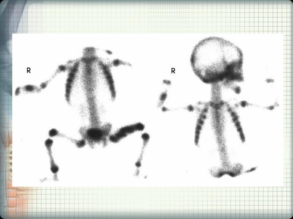

Acknowledgements
• Wikipedia.org
• howstuffworks.com
• radiologyinfo.org