Embed Size (px)
Citation preview
Neutron Diffraction:a general overview
Graeme Blake
Zernike Institute for Advanced Materials
University of Groningen
RUG1
• Elastic scattering of neutrons from matter
• Comparison of neutron and X-ray diffraction for crystallography
• Neutron diffraction for probing magnetism
• Neutron diffraction facilities
• Larmor diffraction
Outline
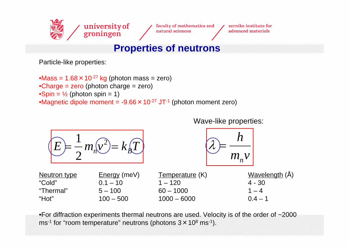
Particle-like properties:
•Mass = 1.68×10⁻²⁷ kg (photon mass = zero)•Charge = zero (photon charge = zero)•Spin = ½ (photon spin = 1)•Magnetic dipole moment = -9.66×10⁻²⁷ JT-1 (photon moment zero)
Neutron type Energy (meV) Temperature (K) Wavelength (Å)“Cold” 0.1 – 10 1 – 120 4 - 30“Thermal” 5 – 100 60 – 1000 1 – 4“Hot” 100 – 500 1000 – 6000 0.4 – 1
•For diffraction experiments thermal neutrons are used. Velocity is of the order of ~2000 ms-1 for “room temperature” neutrons (photons 3×10⁸ ms-1).
TkvmE Bn == 2
21
vmh
n
=λ
Wave-like properties:
Properties of neutrons
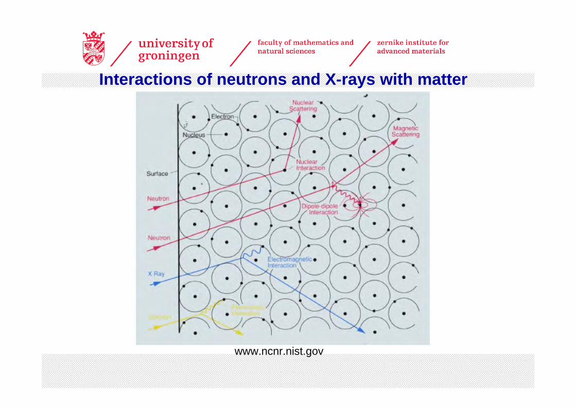
www.ncnr.nist.gov
Interactions of neutrons and X-rays with matter
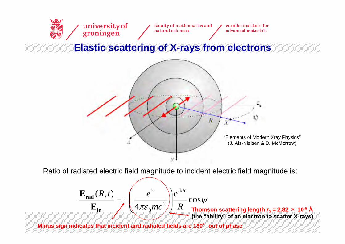
Elastic scattering of X-rays from electrons
Ratio of radiated electric field magnitude to incident electric field magnitude is:
Minus sign indicates that incident and radiated fields are 180°out of phase
ψπε
cose4
),( k
20
2
RmcetR Ri
⎟⎟⎠
⎞⎜⎜⎝
⎛−=
in
rad
EE
Thomson scattering length r0 = 2.82 × 10⁻⁵ Å(the “ability” of an electron to scatter X-rays)
“Elements of Modern Xray Physics”(J. Als-Nielsen & D. McMorrow)
Elastic scattering of neutrons from nuclei
www.ncnr.nist.gov
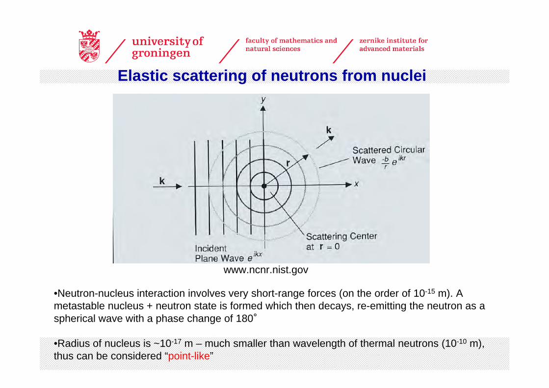
•Neutron-nucleus interaction involves very short-range forces (on the order of 10-15 m). A metastable nucleus + neutron state is formed which then decays, re-emitting the neutron as a spherical wave with a phase change of 180°
•Radius of nucleus is ~10-17 m – much smaller than wavelength of thermal neutrons (10-10 m), thus can be considered “point-like”
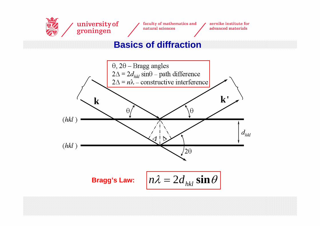
Basics of diffraction
Bragg’s Law: θλ sinhkldn 2=
k k'
Basics of diffraction
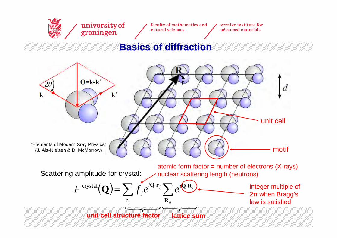
Scattering amplitude for crystal:
( ) ∑ ∑ ⋅⋅=j n
nj iij eefF
r R
RQrQQcrystal
unit cell structure factor lattice sum
unit cell
rj
motif
2θ
integer multiple of 2π when Bragg’s law is satisfied
atomic form factor = number of electrons (X-rays)nuclear scattering length (neutrons)
“Elements of Modern Xray Physics”(J. Als-Nielsen & D. McMorrow)
[http://pd.chem.ucl.ac.uk/pdnn/inst3/neutrons.htm]
Mn
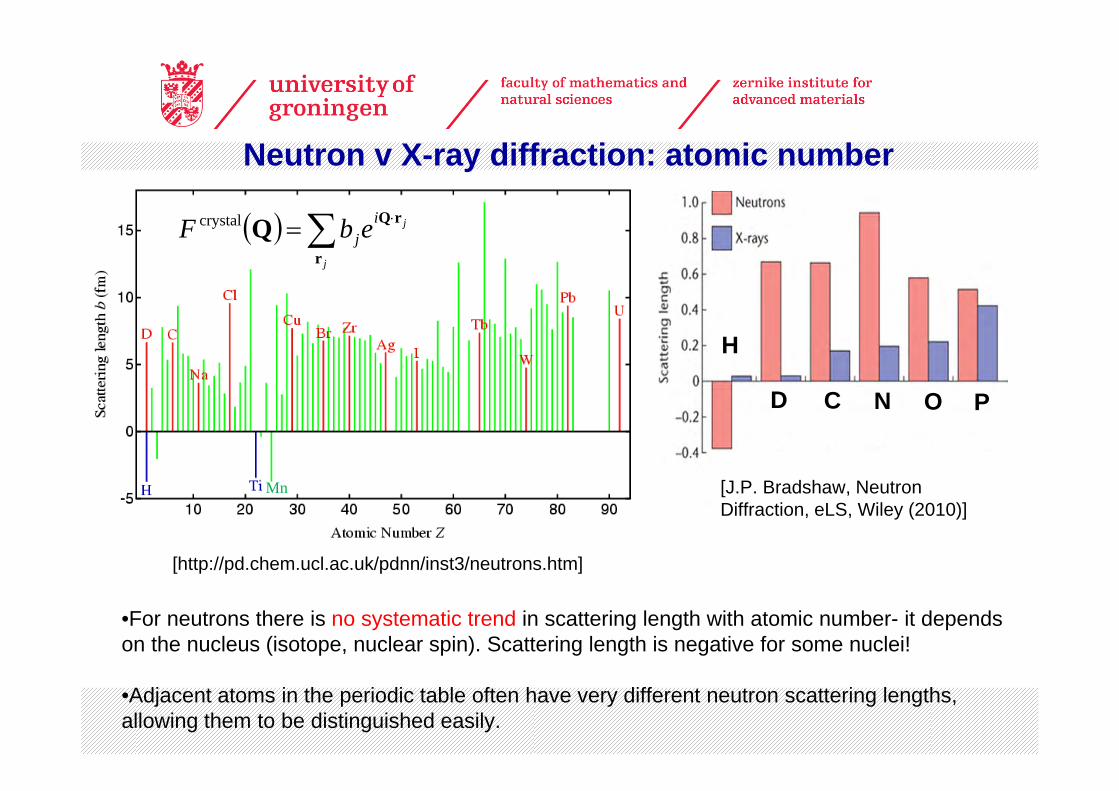
Neutron v X-ray diffraction: atomic number
•For neutrons there is no systematic trend in scattering length with atomic number- it depends on the nucleus (isotope, nuclear spin). Scattering length is negative for some nuclei!
•Adjacent atoms in the periodic table often have very different neutron scattering lengths, allowing them to be distinguished easily.
( ) ∑ ⋅=j
jijebF
r
rQQcrystal
H
D C N O P
[J.P. Bradshaw, Neutron Diffraction, eLS, Wiley (2010)]
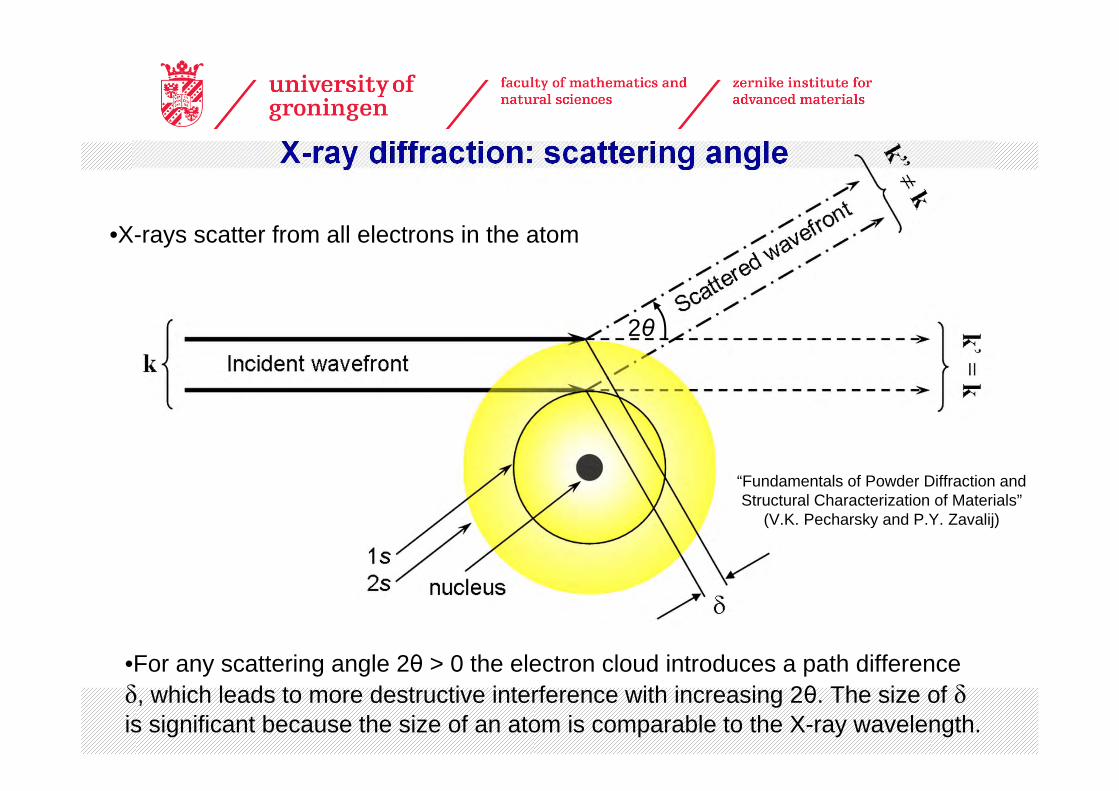
X-ray diffraction: scattering angle
•For any scattering angle 2θ > 0 the electron cloud introduces a path difference δ, which leads to more destructive interference with increasing 2θ. The size of δis significant because the size of an atom is comparable to the X-ray wavelength.
2θ
•X-rays scatter from all electrons in the atom
“Fundamentals of Powder Diffraction and Structural Characterization of Materials”
(V.K. Pecharsky and P.Y. Zavalij)
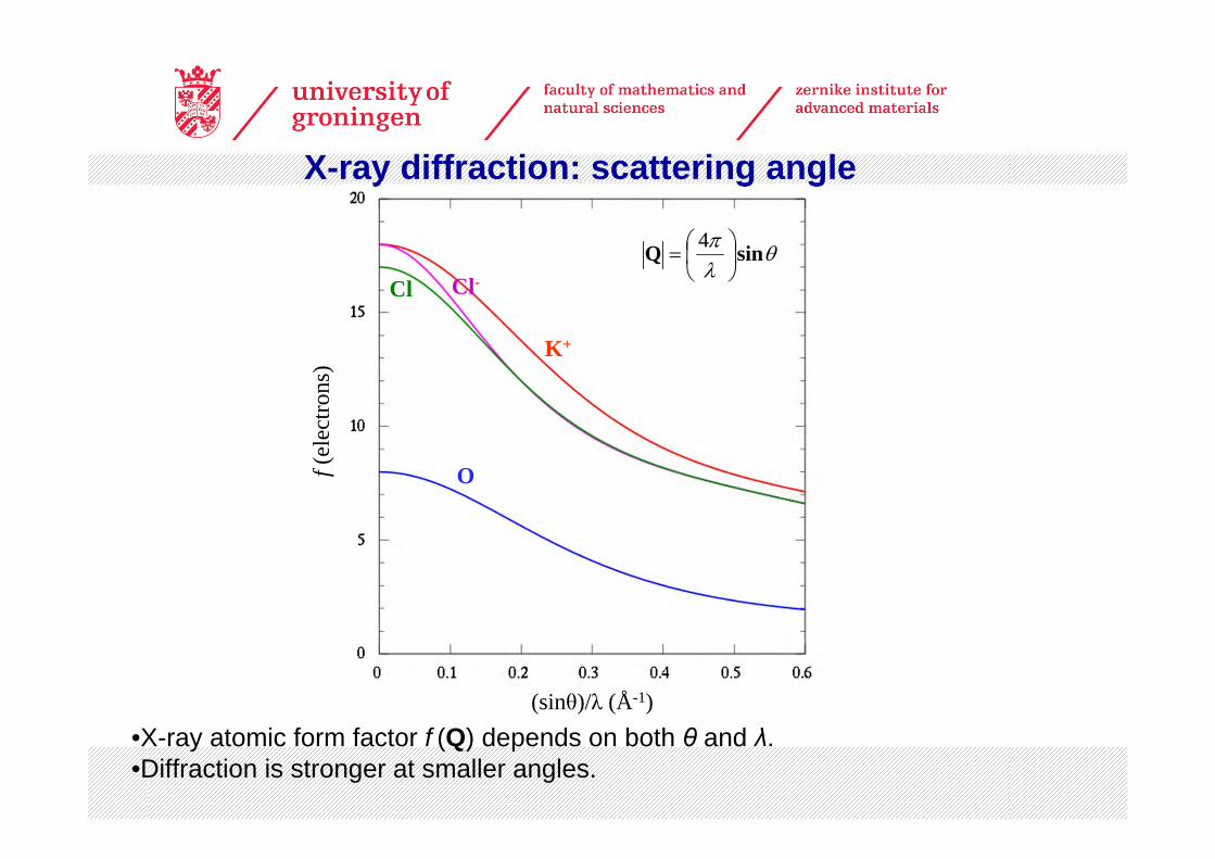
•X-ray atomic form factor f (Q) depends on both θ and λ.•Diffraction is stronger at smaller angles.
X-ray diffraction: scattering angle
(sinθ)/λ (Å-1)
f(el
ectro
ns)
O
Cl Cl-
K+
θλπ sinQ ⎟⎠⎞
⎜⎝⎛=
4
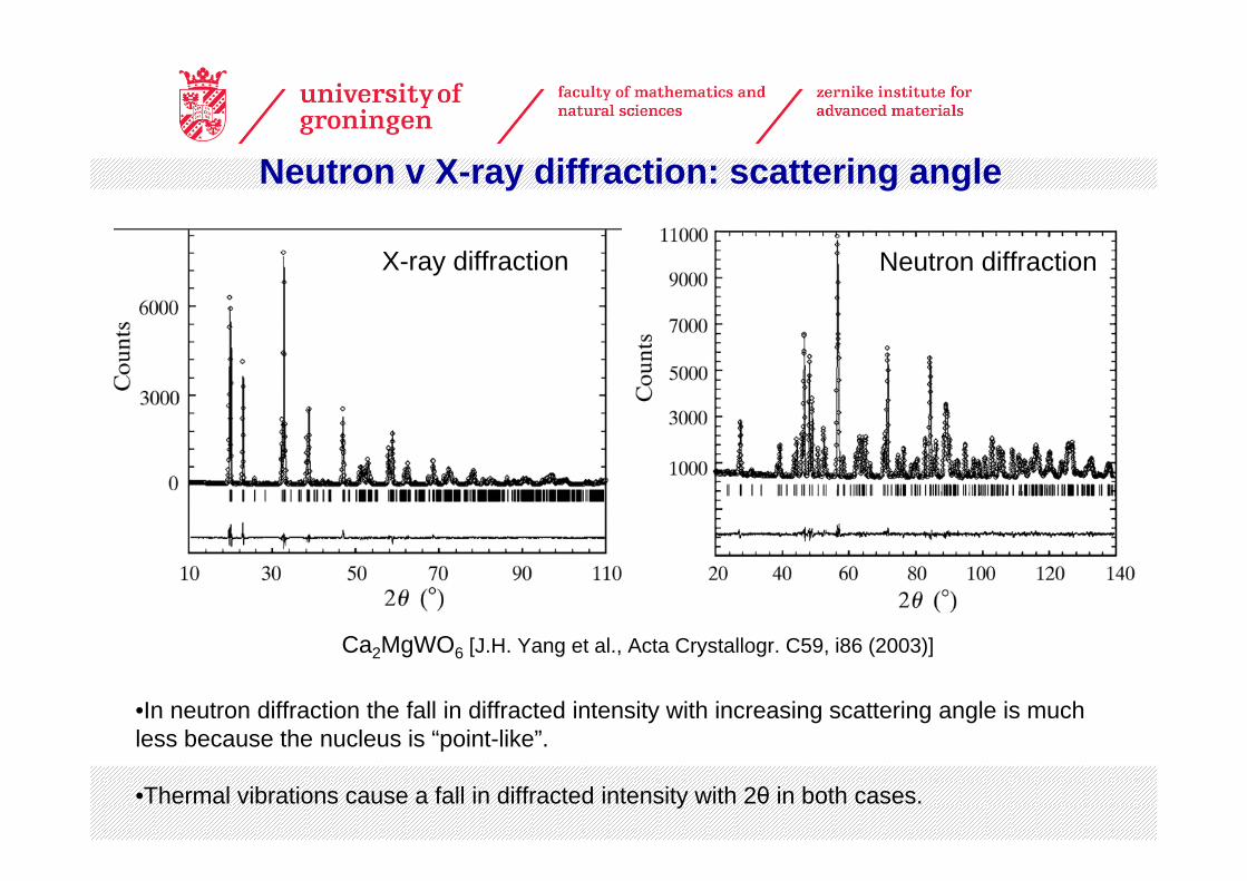
X-ray diffraction Neutron diffraction
•In neutron diffraction the fall in diffracted intensity with increasing scattering angle is much less because the nucleus is “point-like”.
•Thermal vibrations cause a fall in diffracted intensity with 2θ in both cases.
Ca2MgWO6 [J.H. Yang et al., Acta Crystallogr. C59, i86 (2003)]
Neutron v X-ray diffraction: scattering angle
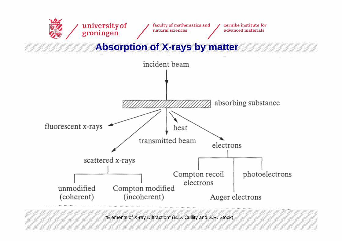
Absorption of X-rays by matter
“Elements of X-ray Diffraction” (B.D. Cullity and S.R. Stock)
www.ncnr.nist.gov
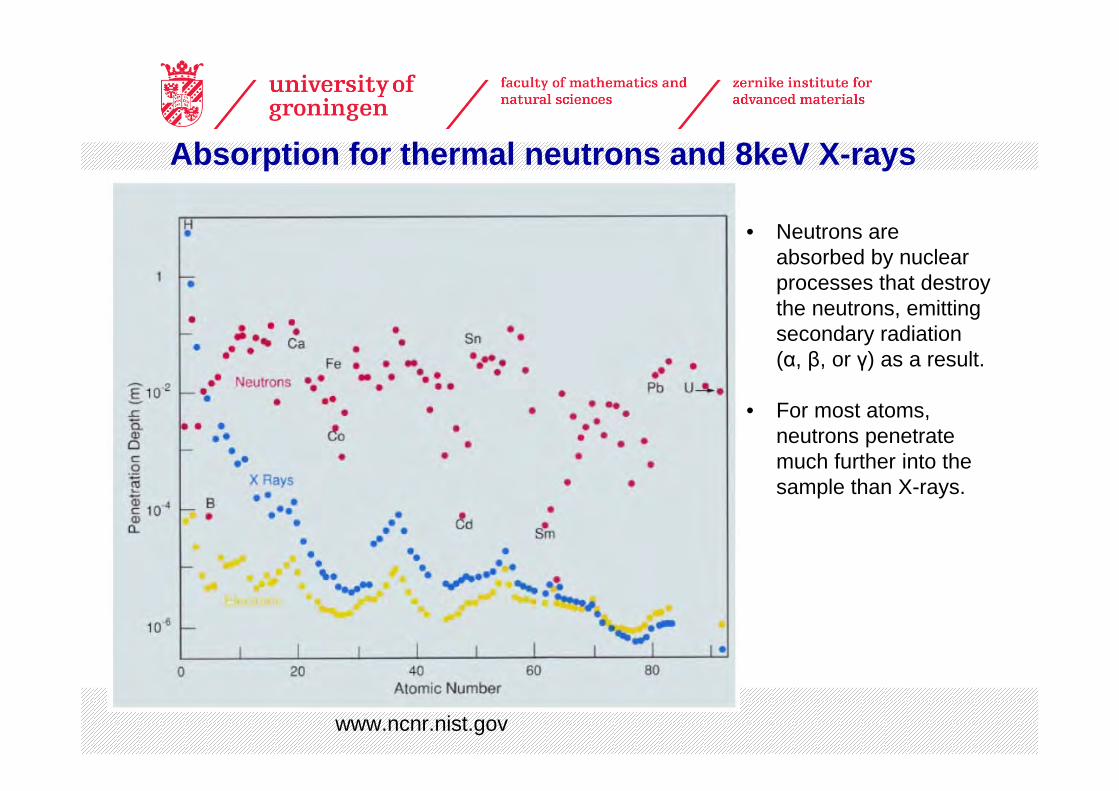
Absorption for thermal neutrons and 8keV X-rays
• Neutrons are absorbed by nuclear processes that destroy the neutrons, emitting secondary radiation (α, β, or γ) as a result.
• For most atoms, neutrons penetrate much further into the sample than X-rays.
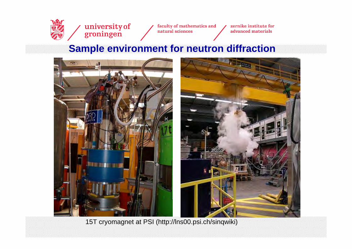
15T cryomagnet at PSI (http://lns00.psi.ch/sinqwiki)
Sample environment for neutron diffraction
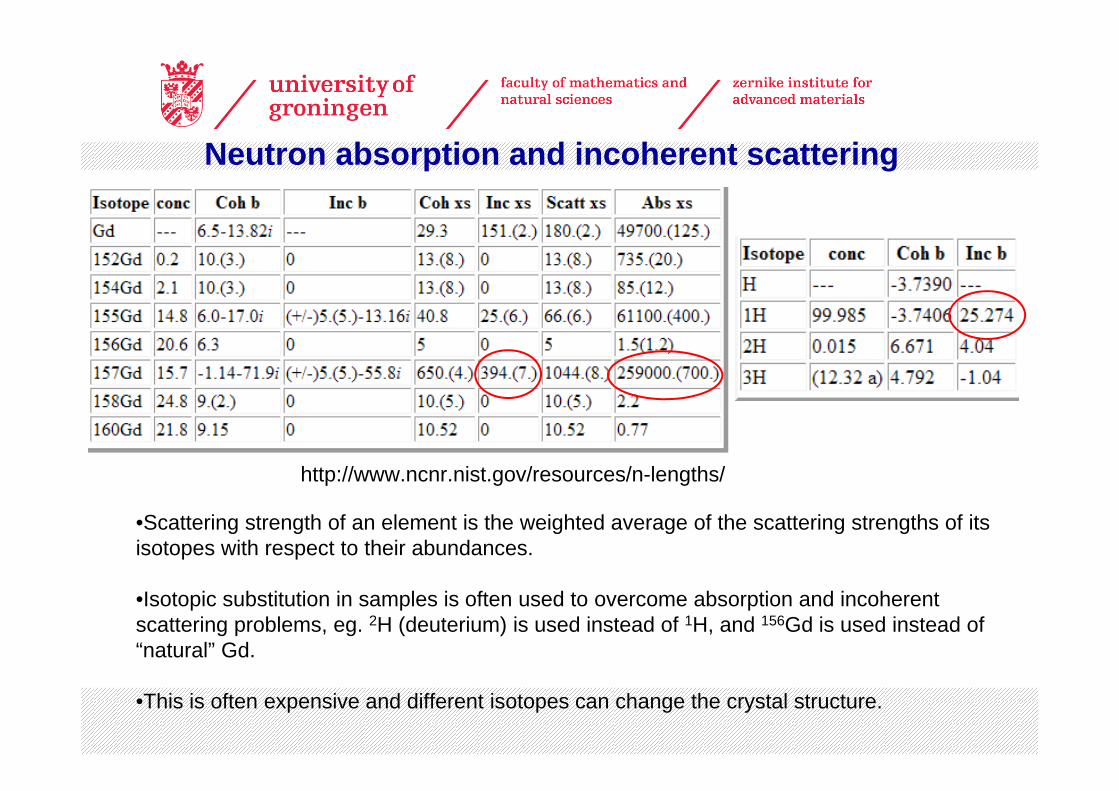
•Scattering strength of an element is the weighted average of the scattering strengths of its isotopes with respect to their abundances.
•Isotopic substitution in samples is often used to overcome absorption and incoherent scattering problems, eg. 2H (deuterium) is used instead of 1H, and 156Gd is used instead of “natural” Gd.
•This is often expensive and different isotopes can change the crystal structure.
http://www.ncnr.nist.gov/resources/n-lengths/
Neutron absorption and incoherent scattering
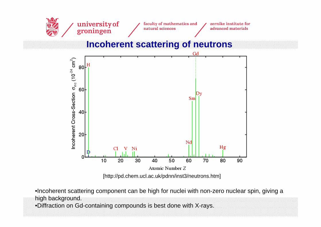
[http://pd.chem.ucl.ac.uk/pdnn/inst3/neutrons.htm]
Incoherent scattering of neutrons
•Incoherent scattering component can be high for nuclei with non-zero nuclear spin, giving a high background.•Diffraction on Gd-containing compounds is best done with X-rays.
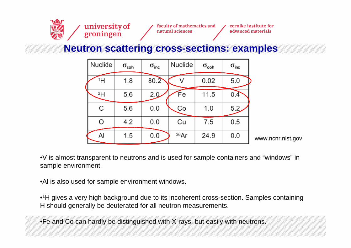
•V is almost transparent to neutrons and is used for sample containers and “windows” in sample environment.
•Al is also used for sample environment windows.
•1H gives a very high background due to its incoherent cross-section. Samples containing H should generally be deuterated for all neutron measurements.
•Fe and Co can hardly be distinguished with X-rays, but easily with neutrons.
Neutron scattering cross-sections: examples
www.ncnr.nist.gov
Neutron diffraction – magnetic structure
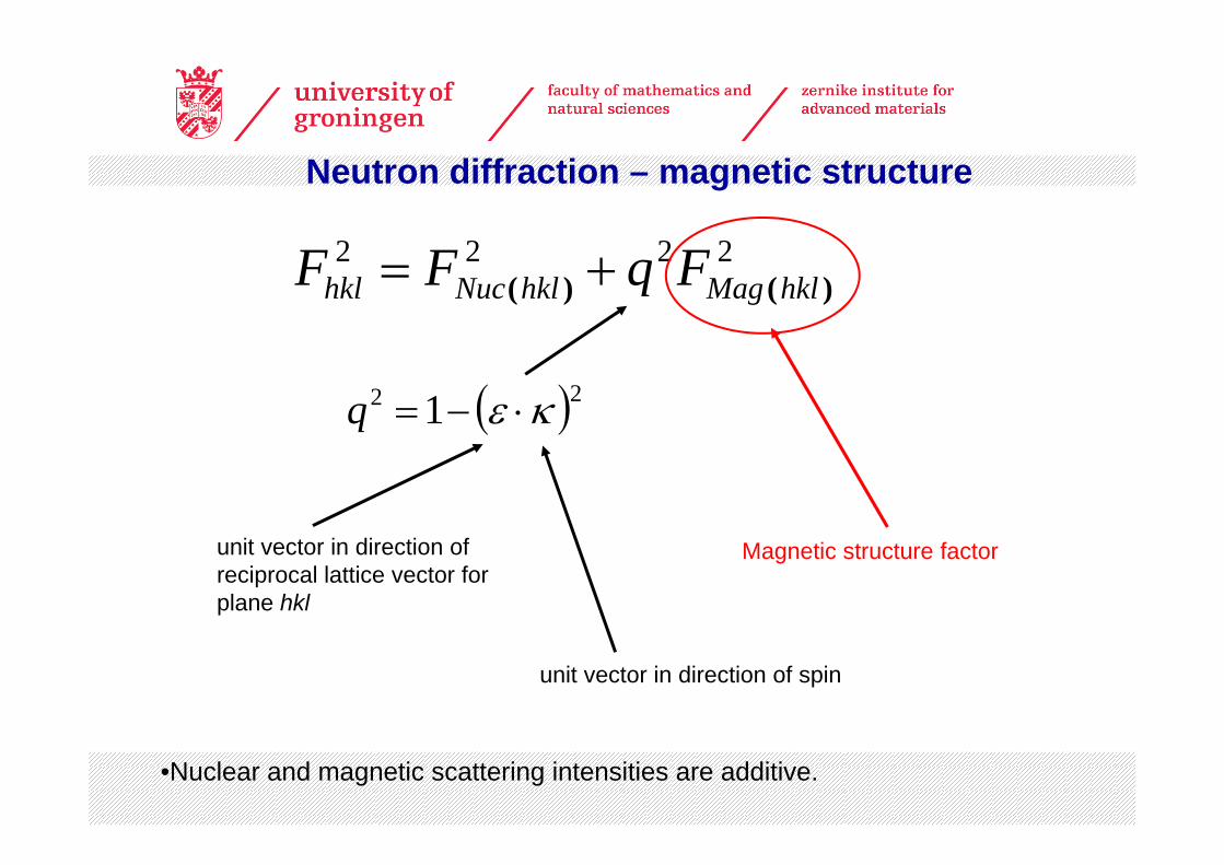
2222)()( hklMaghklNuchkl FqFF +=
( )22 1 κε ⋅−=q
Magnetic structure factor
unit vector in direction of spin
unit vector in direction of reciprocal lattice vector for plane hkl
•Nuclear and magnetic scattering intensities are additive.
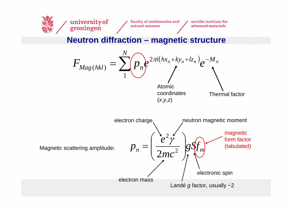
( )∑ −++=N
MlzkyhxinhklMag
nnnn eepF1
2)(
π
mn gSfmcep ⎟⎟
⎠
⎞⎜⎜⎝
⎛= 2
2
2γ
Magnetic scattering amplitude:
Atomic coordinates (x,y,z)
Thermal factor
electron massLandé g factor, usually ~2
electronic spin
magnetic form factor (tabulated)
Neutron diffraction – magnetic structure
electron charge neutron magnetic moment
Neutron diffraction can give:
•The positions of magnetic atoms within the unit cell
•The directions of their ordered magnetic moments
•The magnitudes of their ordered magnetic moments
Neutron diffraction – magnetic structure
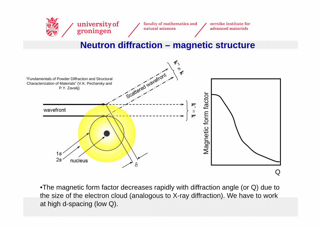
•The magnetic form factor decreases rapidly with diffraction angle (or Q) due to the size of the electron cloud (analogous to X-ray diffraction). We have to work at high d-spacing (low Q).
Mag
netic
form
fact
or
Q
Neutron diffraction – magnetic structure
“Fundamentals of Powder Diffraction and Structural Characterization of Materials” (V.K. Pecharsky and
P.Y. Zavalij)
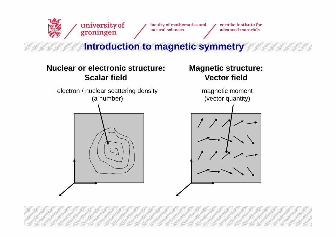
electron / nuclear scattering density(a number)
magnetic moment(vector quantity)
Nuclear or electronic structure:Scalar field
Magnetic structure:Vector field
Introduction to magnetic symmetry
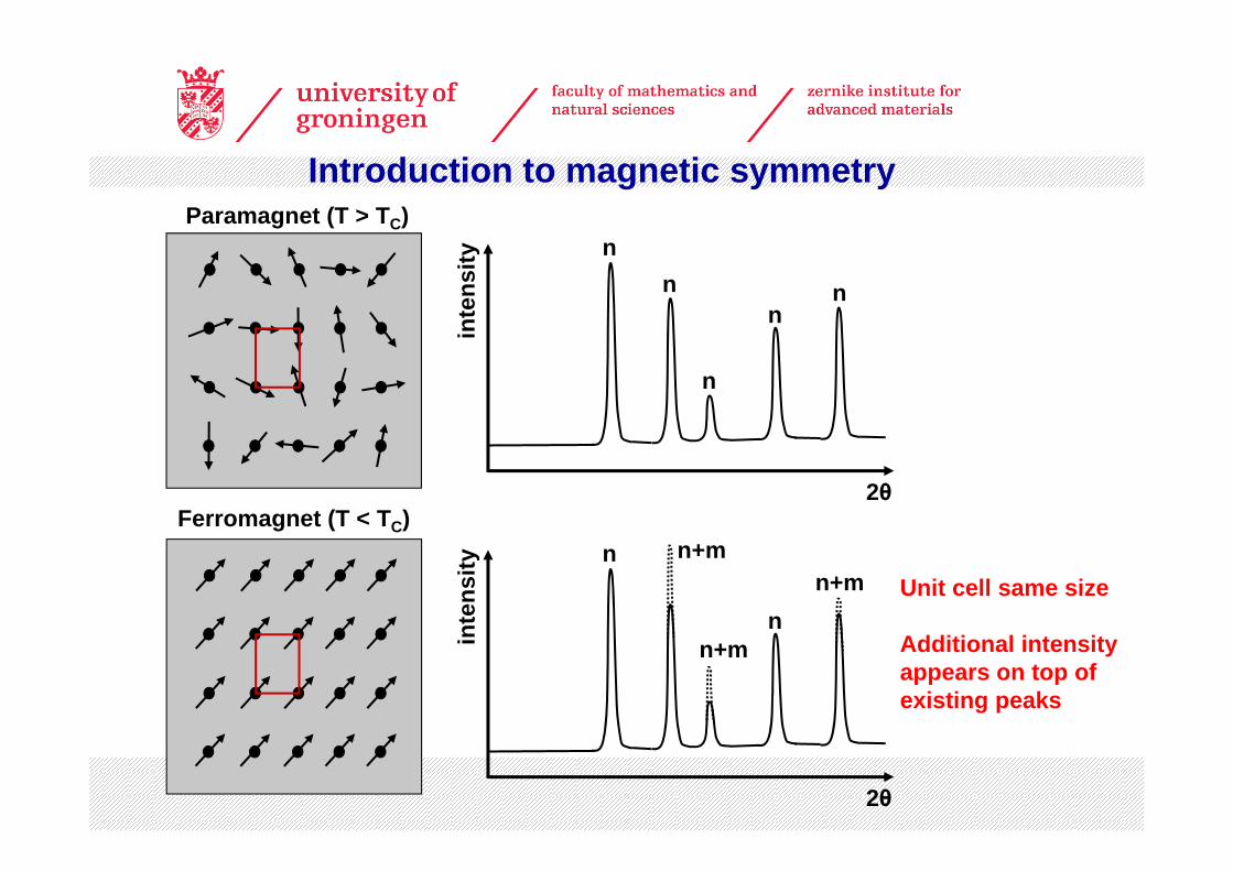
Unit cell same size
Additional intensity appears on top of existing peaks
Paramagnet (T > TC)
Ferromagnet (T < TC)
Introduction to magnetic symmetry
inte
nsity
2θ
nn
n
nn
inte
nsity
2θ
n n+m
n+mn
n+m
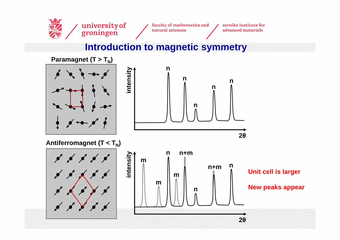
Unit cell is larger
New peaks appear
Paramagnet (T > TN)
Antiferromagnet (T < TN)
Introduction to magnetic symmetry
inte
nsity
2θ
nn
n
nn
inte
nsity
2θ
n n+m
n
nn+mm
m
m
Introduction to magnetic symmetry
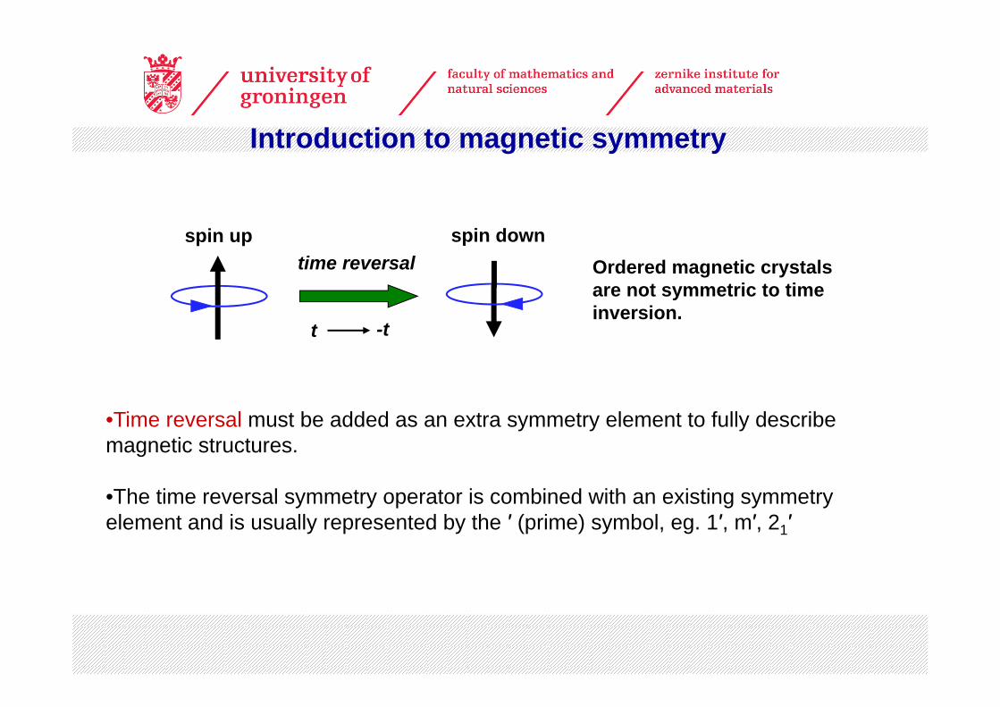
•Time reversal must be added as an extra symmetry element to fully describe magnetic structures.
•The time reversal symmetry operator is combined with an existing symmetry element and is usually represented by the ′ (prime) symbol, eg. 1′, m′, 21′
spin up spin downtime reversal
t -t
Ordered magnetic crystals are not symmetric to time inversion.
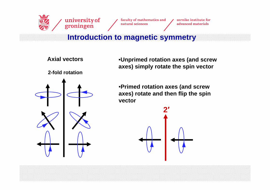
•Unprimed rotation axes (and screw axes) simply rotate the spin vector
•Primed rotation axes (and screw axes) rotate and then flip the spin vector
Introduction to magnetic symmetry
2′
Axial vectors
2-fold rotation
Introduction to magnetic symmetry
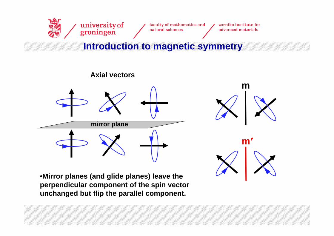
•Mirror planes (and glide planes) leave the perpendicular component of the spin vector unchanged but flip the parallel component.
m
m′
Axial vectors
mirror plane
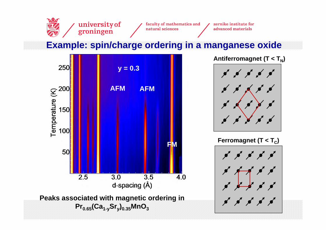
y = 0.3
AFM AFM
FM
Peaks associated with magnetic ordering in Pr0.65(Ca1-ySry)0.35MnO3
Ferromagnet (T < TC)
Antiferromagnet (T < TN)
Example: spin/charge ordering in a manganese oxide

• Sensitivity of neutrons to oxygen allows Mn-O bonding pattern associated with spatial ordering of Mn3+ and Mn4+ to be determined.
Example: spin/charge ordering in a manganese oxide
Charge-ordered, orbital-ordered, spin-ordered state of Pr0.65(Ca0.7Sr0.3)0.35MnO3
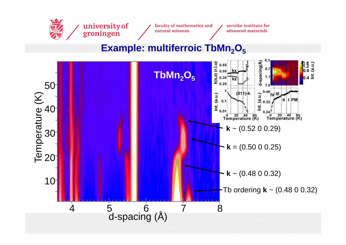
4 5 6 7 8
20
40
30
10
50
d-spacing (Å)
Tem
pera
ture
(K)
k ~ (0.52 0 0.29)
k = (0.50 0 0.25)
k ~ (0.48 0 0.32)
Tb ordering k ~ (0.48 0 0.32)
Example: multiferroic TbMn2O5
TbMn2O5
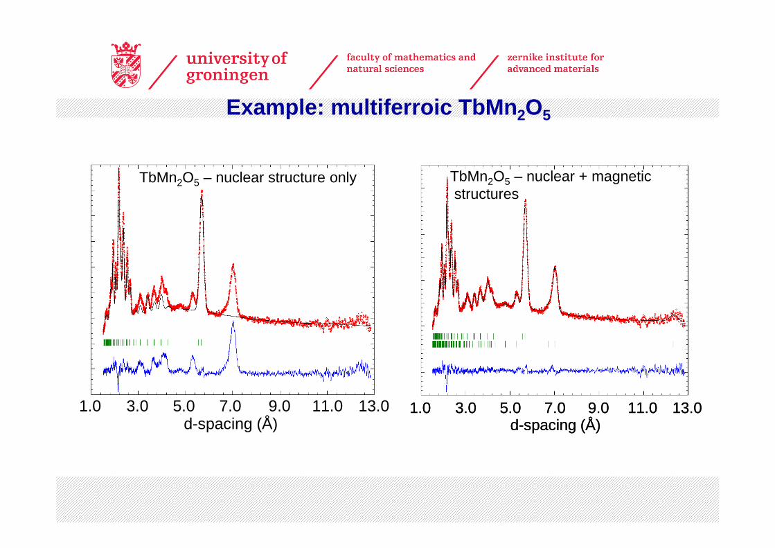
1.0 3.0 5.0 7.0 9.0 11.0d-spacing (Å)
13.0
TbMn2O5 – nuclear structure only
1.0 3.0 5.0 7.0 9.0 11.0d-spacing (Å)
13.01.0 3.0 5.0 7.0 9.0 11.0d-spacing (Å)
13.0
TbMn2O5 – nuclear + magneticstructures
Example: multiferroic TbMn2O5
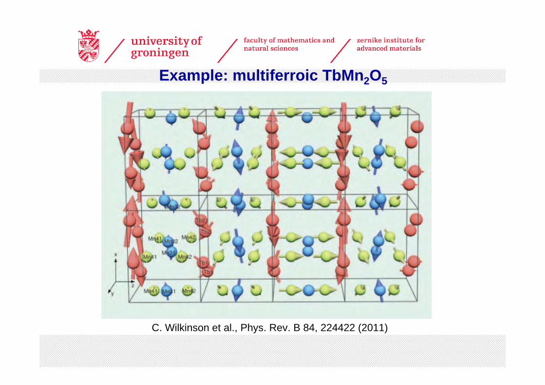
Example: multiferroic TbMn2O5
C. Wilkinson et al., Phys. Rev. B 84, 224422 (2011)
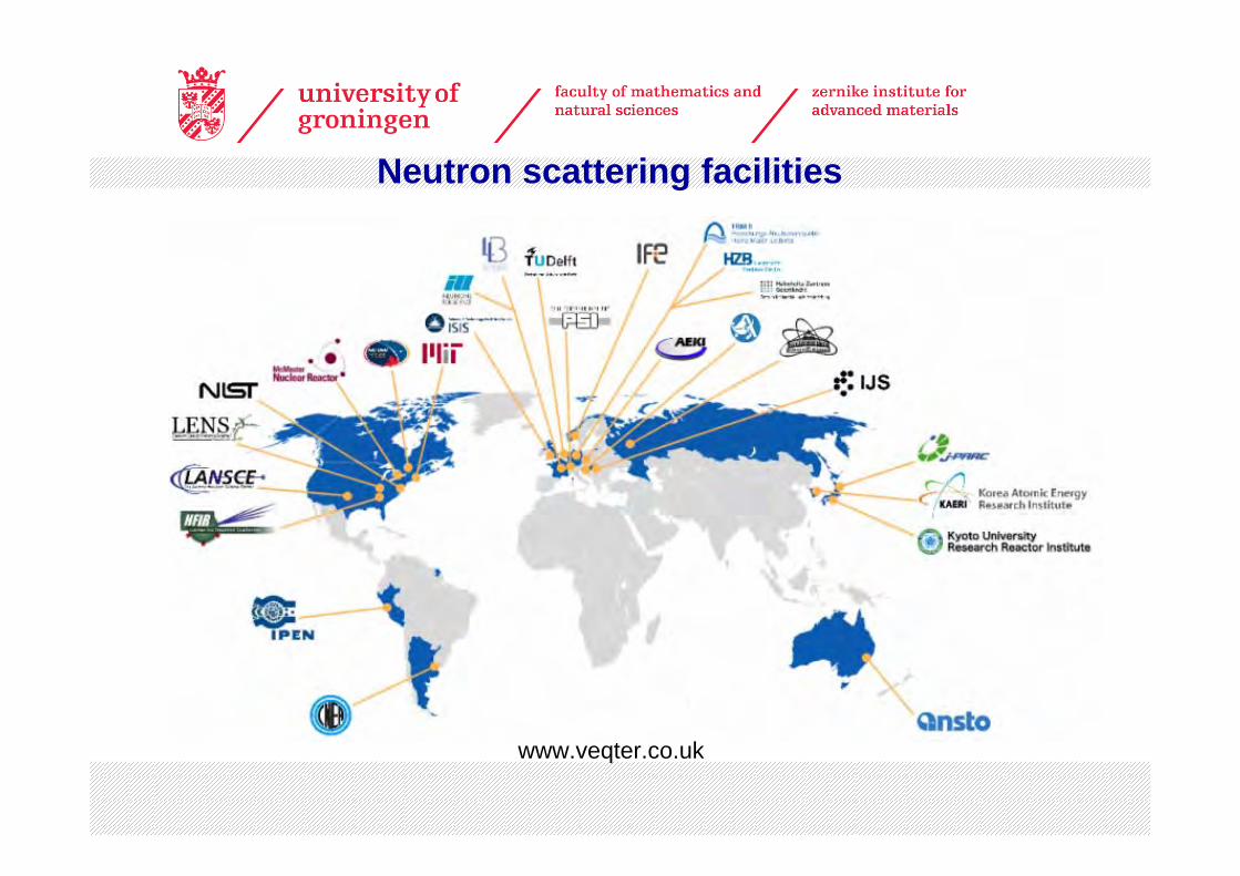
Neutron scattering facilities
www.veqter.co.uk
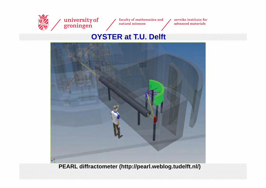
OYSTER at T.U. Delft
PEARL diffractometer (http://pearl.weblog.tudelft.nl/)
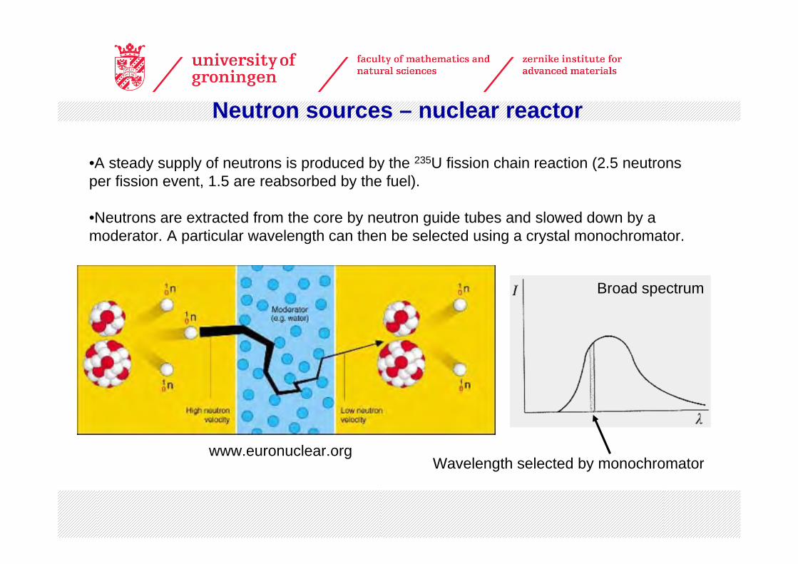
Neutron sources – nuclear reactor
•A steady supply of neutrons is produced by the 235U fission chain reaction (2.5 neutrons per fission event, 1.5 are reabsorbed by the fuel).
•Neutrons are extracted from the core by neutron guide tubes and slowed down by a moderator. A particular wavelength can then be selected using a crystal monochromator.
Wavelength selected by monochromator
Broad spectrum
www.euronuclear.org
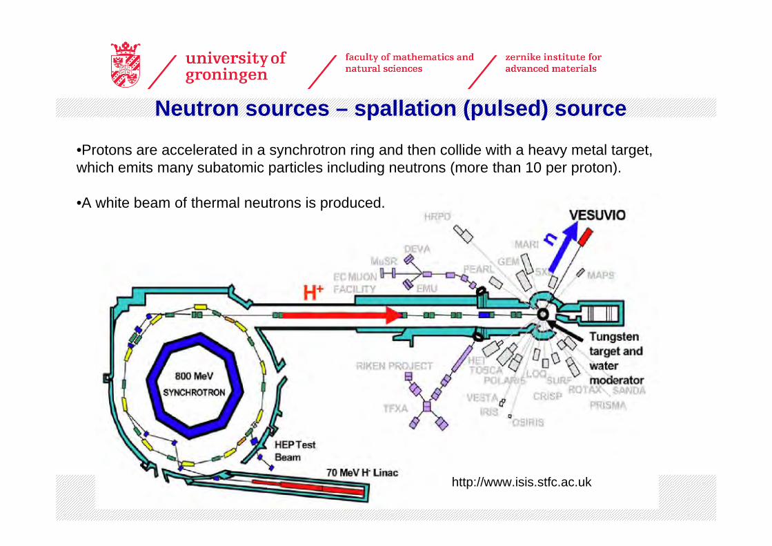
Neutron sources – spallation (pulsed) source
•Protons are accelerated in a synchrotron ring and then collide with a heavy metal target, which emits many subatomic particles including neutrons (more than 10 per proton).
•A white beam of thermal neutrons is produced.
http://www.isis.stfc.ac.uk

Spallation sources – time-of-flight diffraction technique
θθθλ
sin2sin21
sin2 mLht
mvhd hkl
hkl =⎟⎠⎞
⎜⎝⎛⎟⎠⎞
⎜⎝⎛==
neutron mass, velocity(momentum = mv = h/λ)
distance from source to detector (v = L/thkl)
arrival time of neutron at detector
•Detector is kept at fixed position (analogous to X-ray Laue technique).
•Arrival time of diffracted neutrons at detector is determined (“time-of-flight”).
•Often a large bank of many detectors covering a range of angles is used.
•Resolution in dhkl can be increased by increasing distance L from the source.
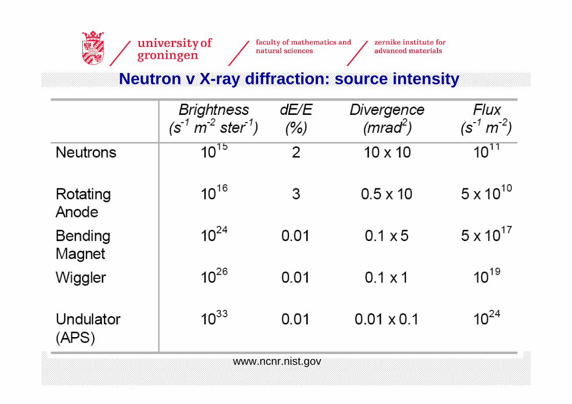
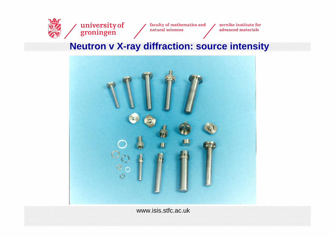
Neutron v X-ray diffraction: source intensity
www.ncnr.nist.gov
www.isis.stfc.ac.uk
Neutron v X-ray diffraction: source intensity
+ Neutrons are highly penetrating towards matter (neutral particles)- absorption is low for most elements. Allows use of heavy sample environment (cryostats, pressure cells, magnets etc.) and probes the whole sample.
+ There is often strong contrast in scattering between neighbouring elements (eg. can distinguish Mn from Fe).
+ Light elements can give strong scattering eg. 2D, 12C, 14N, 16O.
+ Strong interaction with magnetic moments- can determine magnetic structures routinely.
+ No radiation damage to samples- important for organics / biological samples.
- Neutron sources are much weaker than X-ray sources – in general large samples are needed.
- Some nuclei strongly absorb neutrons and cannot be probed eg. 10B, 113Cd, 157Gd.
- Some nuclei are almost transparent to neutrons and cannot easily be probed eg. 51V. Some nuclei have strong incoherent scattering giving high background eg. 1H.
Neutron v X-ray diffraction
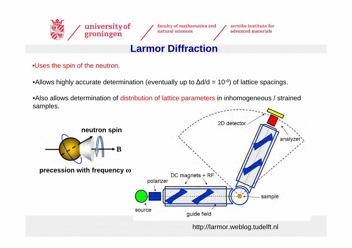
Larmor Diffraction•Uses the spin of the neutron.
http://larmor.weblog.tudelft.nl
B
neutron spin
precession with frequency ω
•Allows highly accurate determination (eventually up to ∆d/d = 10-6) of lattice spacings.
•Also allows determination of distribution of lattice parameters in inhomogeneous / strained samples.
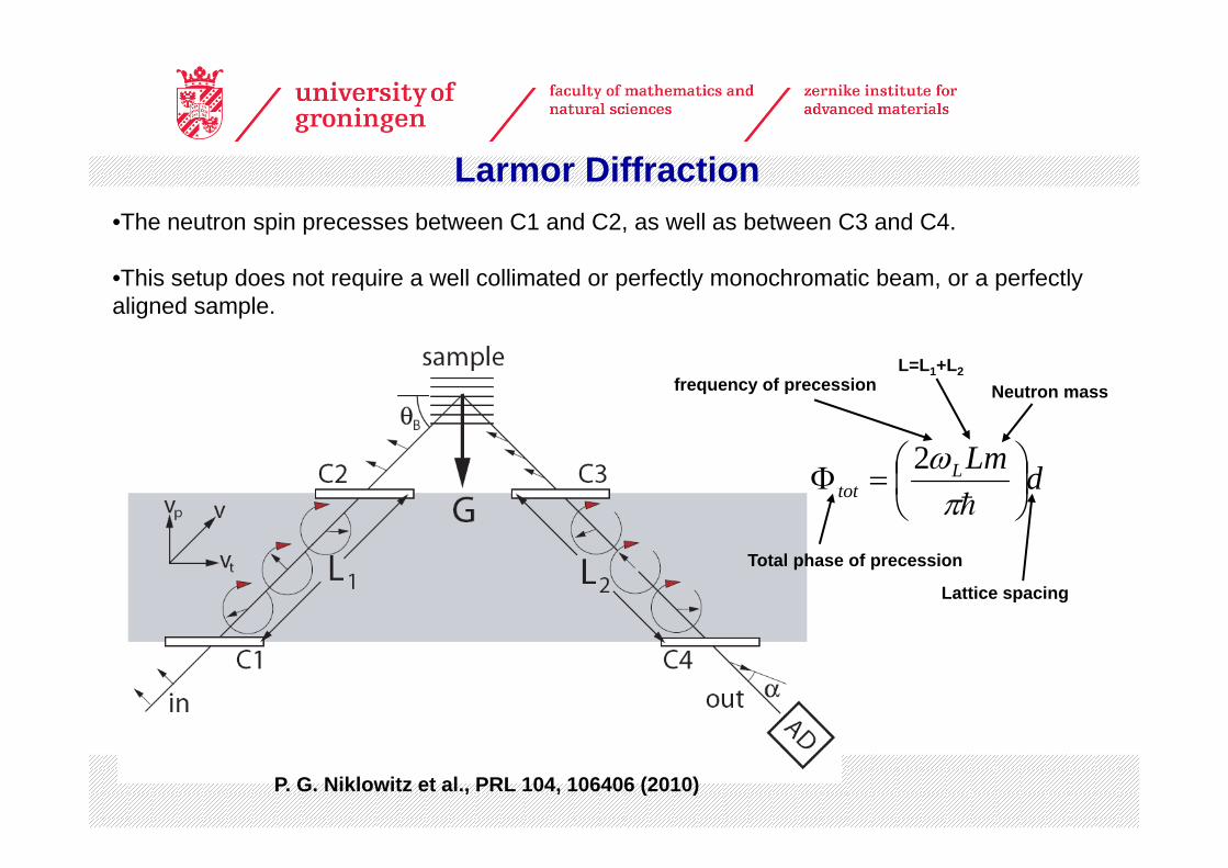
Larmor Diffraction•The neutron spin precesses between C1 and C2, as well as between C3 and C4.
•This setup does not require a well collimated or perfectly monochromatic beam, or a perfectly aligned sample.
P. G. Niklowitz et al., PRL 104, 106406 (2010)
Total phase of precession
Lattice spacing
frequency of precessionL=L1+L2
Neutron mass
dLmLtot ⎟
⎠⎞
⎜⎝⎛=Φ
hπω2
Larmor Diffraction
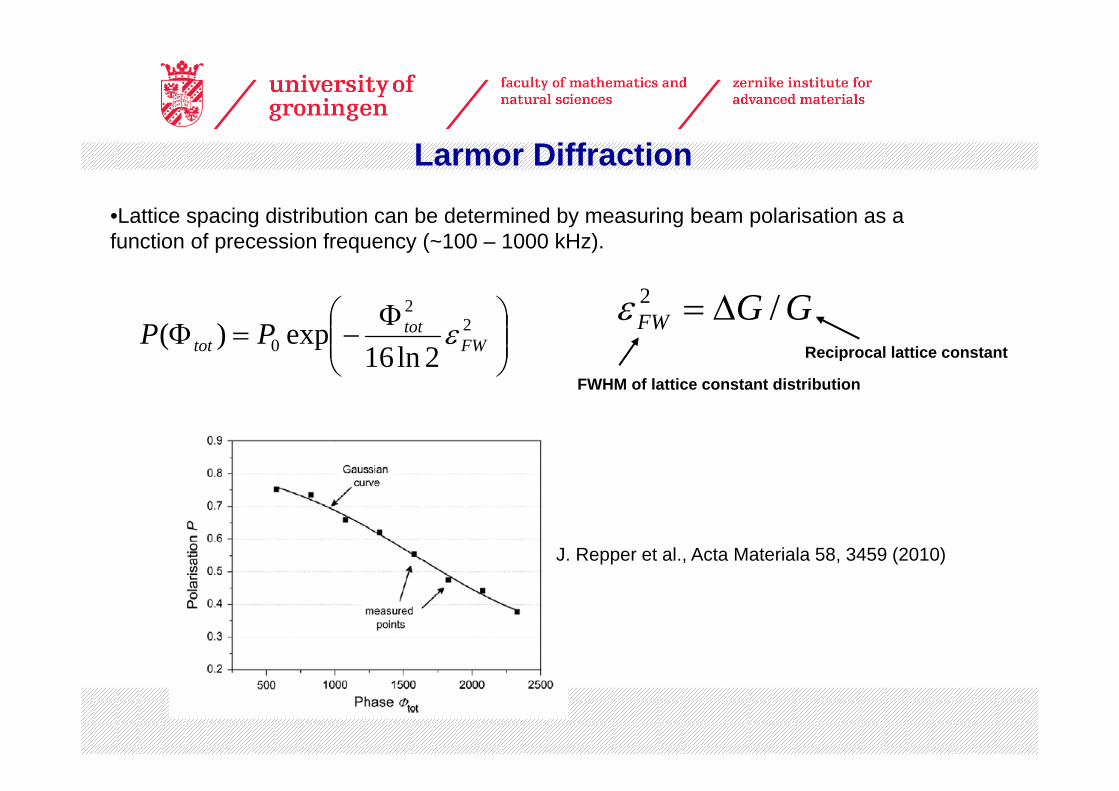
•Lattice spacing distribution can be determined by measuring beam polarisation as a function of precession frequency (~100 – 1000 kHz).
⎟⎟⎠
⎞⎜⎜⎝
⎛ Φ−=Φ 2
2
0 2ln16exp)( FW
tottot PP ε
Reciprocal lattice constant
FWHM of lattice constant distribution
GGFW /2 Δ=ε
J. Repper et al., Acta Materiala 58, 3459 (2010)
Larmor Diffraction
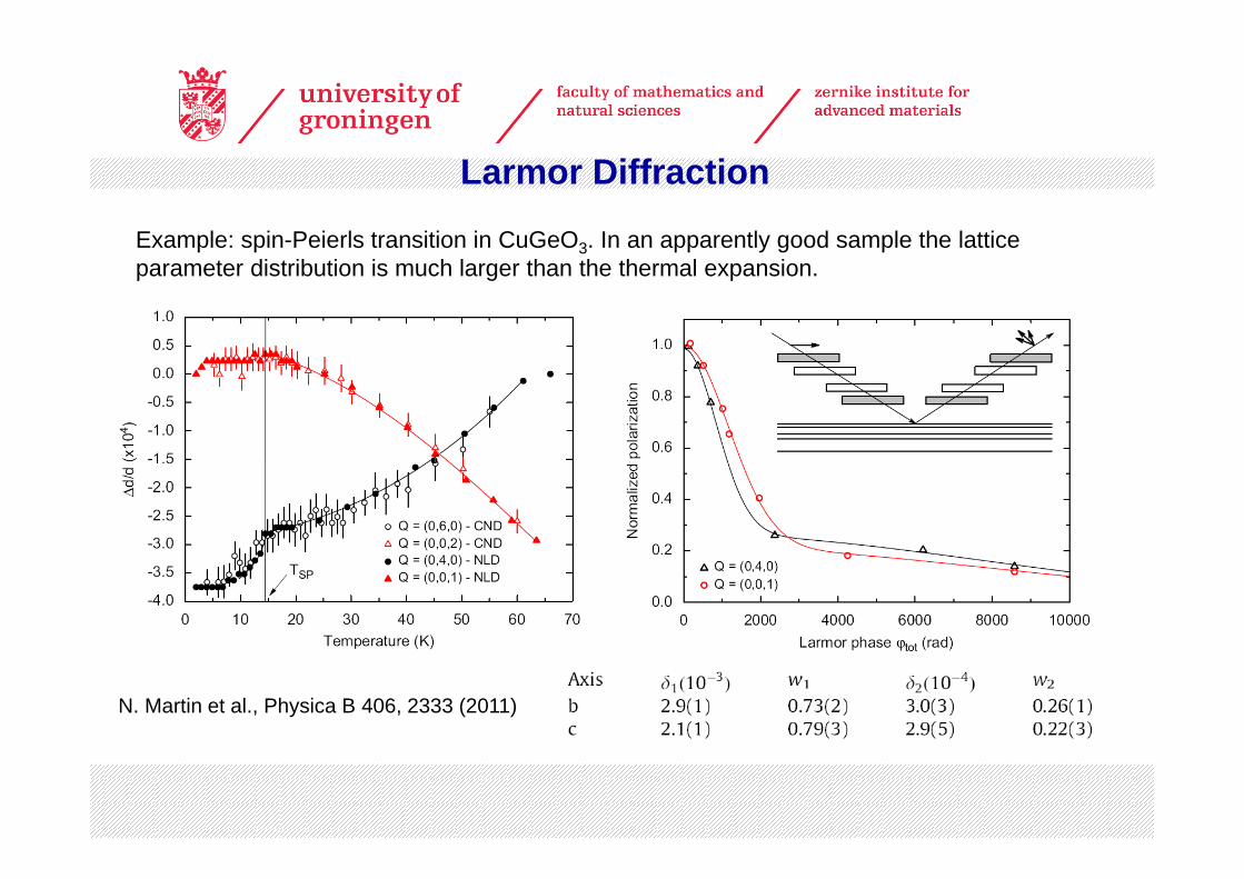
Example: spin-Peierls transition in CuGeO3. In an apparently good sample the lattice parameter distribution is much larger than the thermal expansion.
N. Martin et al., Physica B 406, 2333 (2011)

Larmor Diffraction
• Study subtle (magnetically induced?) structural distortions that are beyond the best resolution of “standard” X-ray / neutron diffraction
• Determine the lattice constants and distribution of lattice constants associated with domains and nanostructured materials
• Study structural changes associated with classical or quantum phase transitions
• Gain clues as to the sizes and shapes of structural domains, density of domain walls.
• Probe the above at high / low temperature, high pressure
• The time-of-flight technique at ISIS should allow powders to be measured.
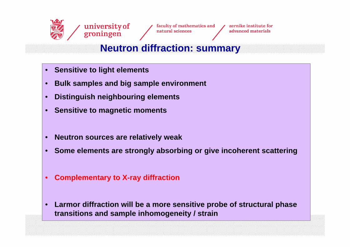
• Sensitive to light elements
• Bulk samples and big sample environment
• Distinguish neighbouring elements
• Sensitive to magnetic moments
• Neutron sources are relatively weak
• Some elements are strongly absorbing or give incoherent scattering
• Complementary to X-ray diffraction
• Larmor diffraction will be a more sensitive probe of structural phase transitions and sample inhomogeneity / strain
Neutron diffraction: summary