Embed Size (px)
Citation preview

September 1-2, 2003 ECNS03 Introductory Course "Neutron Stress Analysis" 1
Strain and Stress Analysis byNeutron Diffraction
Monica CerettiLaboratoire Léon Brillouin
CEA Saclay, 91191 Gif Sur Yvette
September 1-2, 2003 ECNS03 Introductory Course "Neutron Stress Analysis" 2
Outline
• Introduction:• Definition and classification of residual stresses• Principles of diffraction stress measurements
• Use of neutrons• Experimental aspects• Examples• A look to the future
September 1-2, 2003 ECNS03 Introductory Course "Neutron Stress Analysis" 3
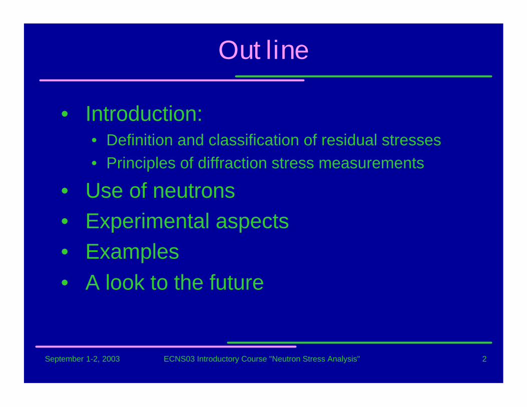
Residual Stresses: definition andclassification
• Residual stress of the first order (σI, macro) arenearly homogeneous across large areas (several grainsof the material)
• Residual stresses of the second order (σII, meso) arenearly homogeneous across smaller areas, of the orderof some grains or phases of a material
• Residual stresses of the third order (σIII, micro) areinhomogeneous across submicroscopic areas of thematerial, several atomic distances within a grain.
x
σ
σ I
σ I β
σ I α
σ II α
σ II β
σ III α
σ III β
xβ
α
Residual Stresses: « self equilibrating internal stresses existing in a free bodywith no external forces or constraints on its boundary » and under uniformtemperature conditions

September 1-2, 2003 ECNS03 Introductory Course "Neutron Stress Analysis" 4
Material processing
Casting(thermal residual stresses)
Reshaping
(inhomogeneous plastic deformation)
Cutting
(working RS: grinding, honing)
Joining
(brazing, welding)
Coating
Material properties(case hardening)
Material load
Mechanical
e.g. rolling
Thermal temperaturefields
Chemical H-diffusion
Formation of Residual Stresses
E.g. mutiphasematerials, inclusion
Material
RS superimpose to applied stressesduring service life
RS can affect the mechanicalbehaviour of a component
Their evaluation is fundamental
September 1-2, 2003 ECNS03 Introductory Course "Neutron Stress Analysis" 5
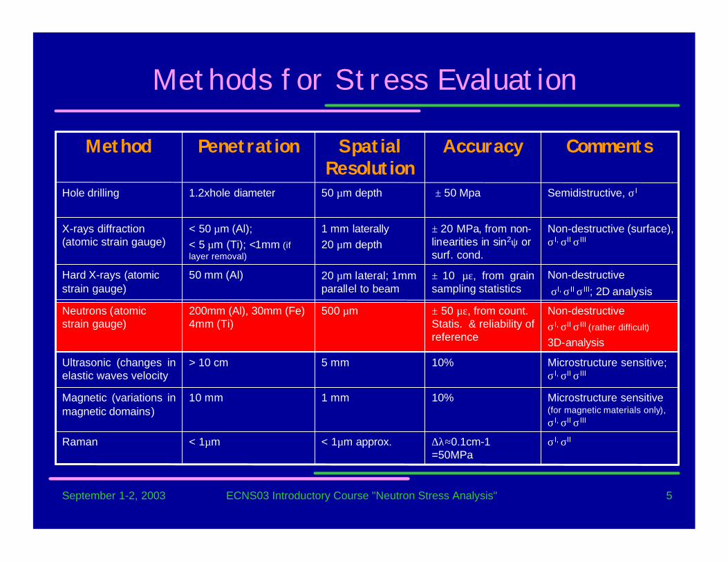
Methods for Stress Evaluation
σI, σII∆λ≈0.1cm-1=50MPa
< 1µm approx.< 1µmRaman
Microstructure sensitive(for magnetic materials only),σI, σII σIII
10%1 mm10 mmMagnetic (variations inmagnetic domains)
Microstructure sensitive;σI, σII σIII
10%5 mm> 10 cmUltrasonic (changes inelastic waves velocity
Non-destructiveσI, σII σIII (rather difficult)
3D-analysis
± 50 µε, from count.Statis. & reliability ofreference
500 µm200mm (Al), 30mm (Fe)4mm (Ti)
Neutrons (atomicstrain gauge)
Non-destructive σI, σII σIII; 2D analysis
± 10 µε, from grainsampling statistics
20 µm lateral; 1mmparallel to beam
50 mm (Al)Hard X-rays (atomicstrain gauge)
Non-destructive (surface),σI, σII σIII
± 20 MPa, from non-linearities in sin2ψ orsurf. cond.
1 mm laterally20 µm depth
< 50 µm (Al);< 5 µm (Ti); <1mm (iflayer removal)
X-rays diffraction(atomic strain gauge)
Semidistructive, σI ± 50 Mpa50 µm depth1.2xhole diameterHole drilling
CommentsAccuracySpatialResolution
PenetrationMethod

September 1-2, 2003 ECNS03 Introductory Course "Neutron Stress Analysis" 6
Neutrons vs. X-Rays
0
0.2
0.4
0.6
0.8
1
0 5 10 15 20 25
Tra
nsm
issi
on
Penetration path (mm)
Al
Ti
W
FeNi
2.0933116.601.05W
17.04073.731.86Ni
2.8624246.191.12Fe
7.3993815.40.45Ti
52.913169.30.10Al
t50% (µm)µ (cm-1)t50% (mm)µ (cm-1)Z
RaysX-ronsNeut
September 1-2, 2003 ECNS03 Introductory Course "Neutron Stress Analysis" 7
• Introduced in the 80’S
• rapid developments: it is the only technique which allows a nondestructive analysis of the stress field in bulk samples
• neutron can deeply penetrate in most materials
• intensity of a neutron monochromatic beam is much lower than that ofX-ray tube
• high neutron source• long measuring time• spatial resolution of ~ 1mm3
Neutron Diffraction Applied to StressAnalysis
September 1-2, 2003 ECNS03 Introductory Course "Neutron Stress Analysis" 8
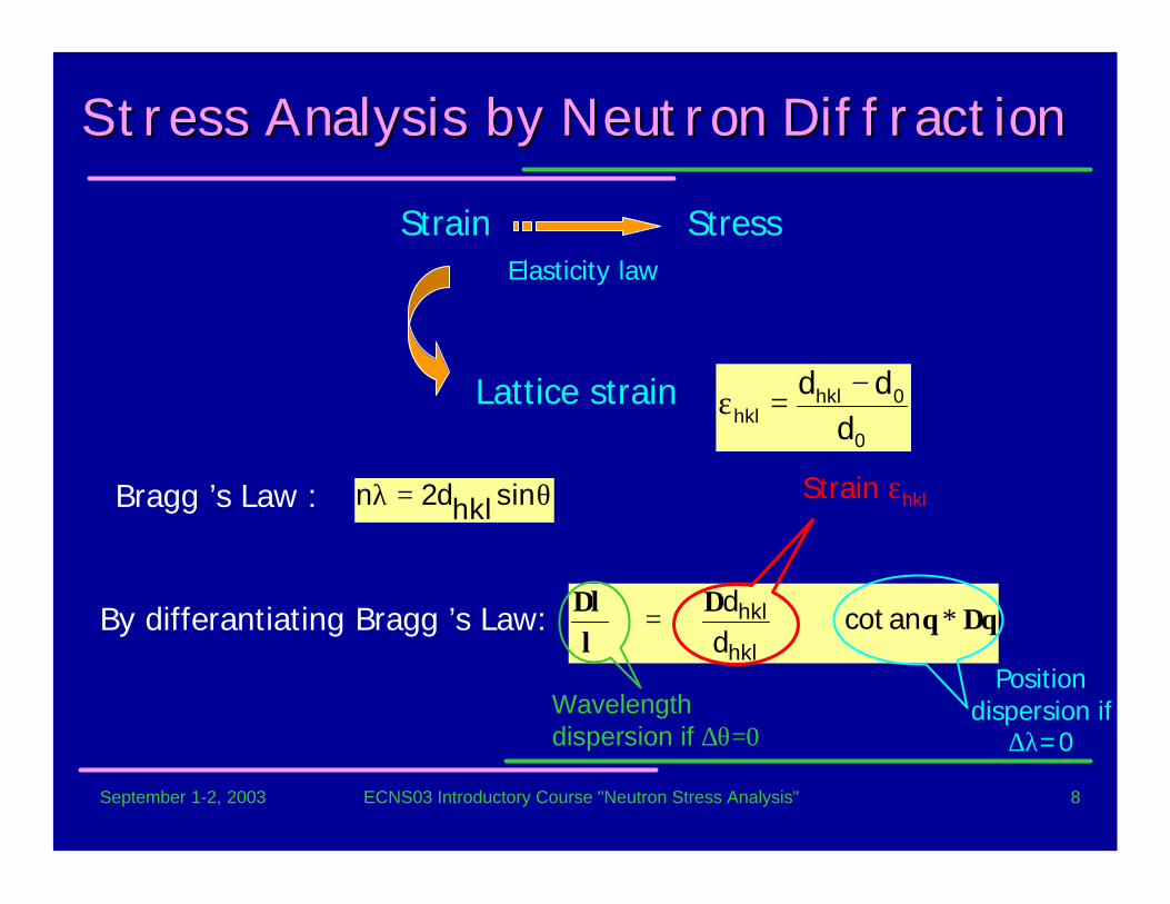
Stress Stress AnalysisAnalysis by Neutron Diffraction by Neutron Diffraction
Bragg ’s Law : θ=λ sinhkld2n
Strain StressElasticity law
θ∆θ∆λλ∆ ∗+= ancot
dd
hkl
hklBy differantiating Bragg ’s Law:
Strain εhkl
Positiondispersion if
∆λ=0Wavelengthdispersion if ∆θ=0
Lattice strain0
0hklhkl d
dd −=ε
September 1-2, 2003 ECNS03 Introductory Course "Neutron Stress Analysis" 9
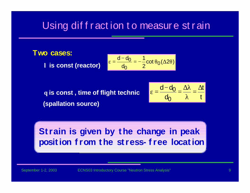
Two cases:� λ is const (reactor)
� θ is const , time of flight technic
(spallation source)
Using diffraction to measure strain
Strain is given by the change in peakposition from the stress-free location
)2(cot21
ddd
00
0 θ∆θ−=−
=ε
tt
ddd
0
0 ∆=λλ∆=−=ε
September 1-2, 2003 ECNS03 Introductory Course "Neutron Stress Analysis" 10
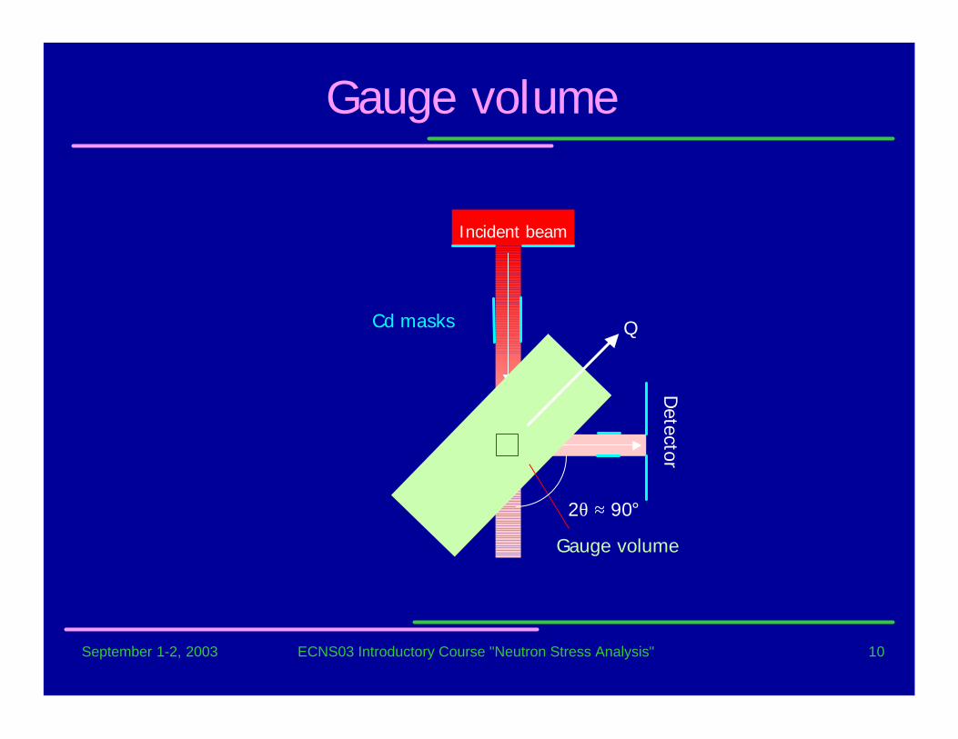
Detector
Incident beam
Gauge volume
QCd masks
2θ ≈ 90°
Gauge volume
September 1-2, 2003 ECNS03 Introductory Course "Neutron Stress Analysis" 11
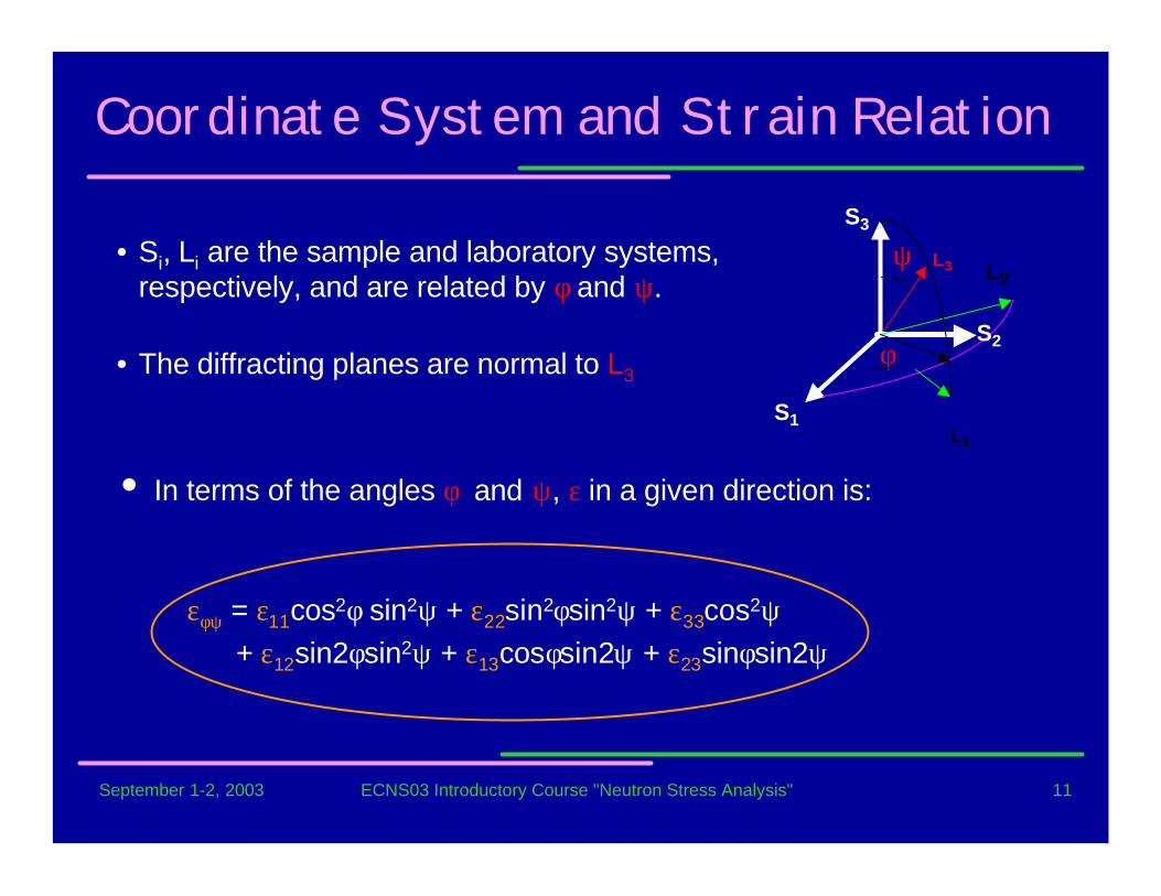
Coordinate System and Strain Relation
• In terms of the angles φ and ψ, ε in a given direction is:
εφψ = ε11cos2φ sin2ψ + ε22sin2φsin2ψ + ε33cos2ψ + ε12sin2φsin2ψ + ε13cosφsin2ψ + ε23sinφsin2ψ
ψ
φ
S3
S2
L2
S1L1
L3• Si, Li are the sample and laboratory systems,
respectively, and are related by φ and ψ.
• The diffracting planes are normal to L3
September 1-2, 2003 ECNS03 Introductory Course "Neutron Stress Analysis" 12
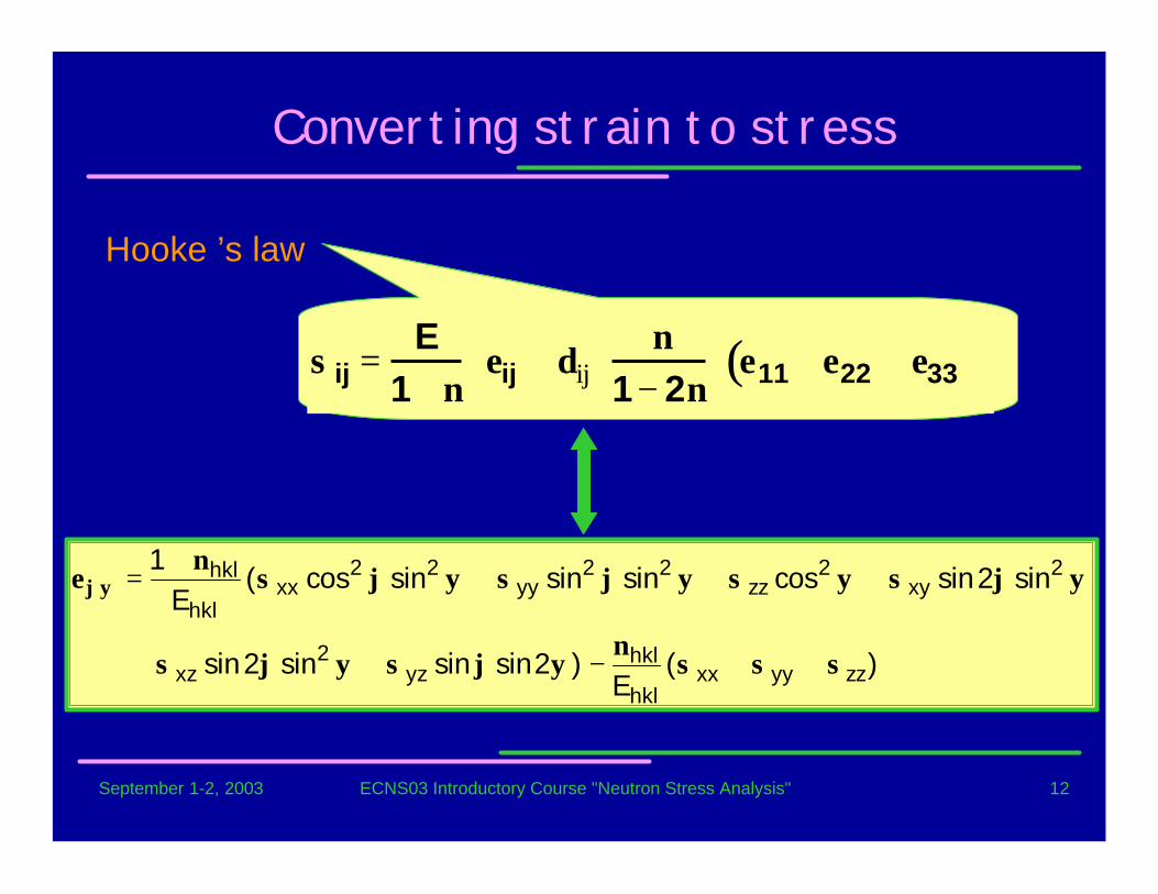
Converting strain to stress
Hooke ’s law
)(E
)2sinsinsin2sin
sin2sincossinsinsincos(E
1
zzyyxxhkl
hklyz
2xz
2xy
2zz
22yy
22xx
hkl
hkl
σσσν
ψϕσψϕσ
ψϕσψσψϕσψϕσν
εϕψ
++−++
++++
=
σij =E
1+ νεij + δij
ν1− 2ν
ε11 + ε22 + ε33( )
September 1-2, 2003 ECNS03 Introductory Course "Neutron Stress Analysis" 13
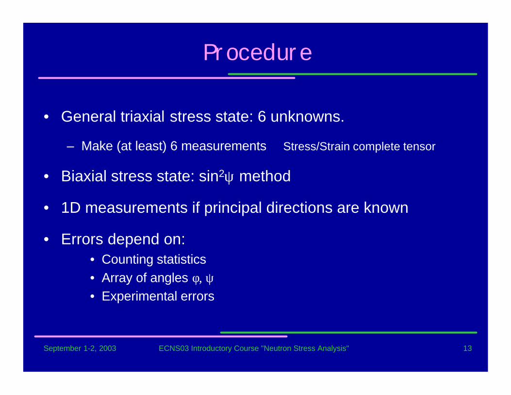
Procedure
• General triaxial stress state: 6 unknowns.
– Make (at least) 6 measurements Stress/Strain complete tensor
• Biaxial stress state: sin2ψ method
• 1D measurements if principal directions are known
• Errors depend on:• Counting statistics• Array of angles φ, ψ• Experimental errors
September 1-2, 2003 ECNS03 Introductory Course "Neutron Stress Analysis" 14
Four ideas
• It is strain that is actually measured.
• Residual strain changes interplanar spacings, whichshifts the positions of diffraction peaks.
• Strain is resolved differently in different physicaldirections in the sample.
• Engineering materials are polycrystalline, so somegrains are always oriented to diffract enabling stresstensors to be determined.
September 1-2, 2003 ECNS03 Introductory Course "Neutron Stress Analysis" 15
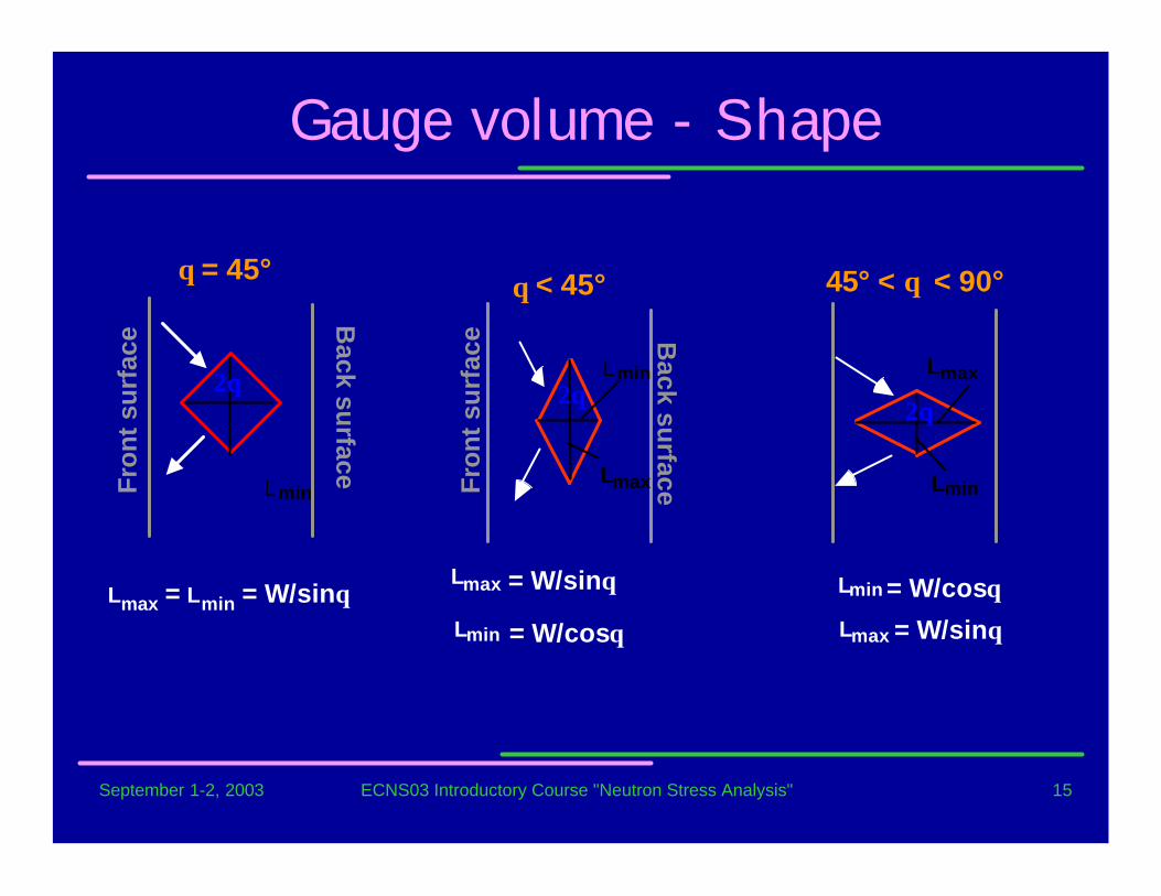
Lmin
Lmin
maxL
maxL
2θ2θ
θ < 45° 45° < θ < 90°
Lmin
maxL = W/sinθ
= W/cosθ
= W/cosθ
maxL
Lmin
= W/sinθ
Fron
t su
rfac
e Back su
rface
Gauge volume - Shape
LminFron
t su
rfac
e Back su
rface
θ = 45°
2θ
Lmax = Lmin = W/sinθ
September 1-2, 2003 ECNS03 Introductory Course "Neutron Stress Analysis" 16
Gage volume - issues
• Size– Small enough for spatial resolution– Large enough for sufficient intensity
• Shape– Confine measurement to region of interest– Neutron measurements around 90° 2θ
• Geometry and optics– Can be tricky

September 1-2, 2003 ECNS03 Introductory Course "Neutron Stress Analysis" 17
Texture - preferred orientation
• Conversion of strain to stress:– Elastic constants altered– Can change with sample orientation
• Peak intensities and shape:– Intensities can vary strongly with orientation– Shapes can also change, affecting accuracy
• Can be checked by:– Measurements of intensity versus sample orientation– Powder pattern intensity analysis
• If possible, use experimentally determined diffraction elasticconstants from same material
September 1-2, 2003 ECNS03 Introductory Course "Neutron Stress Analysis" 18
Stress-free standards
• Generally require peak positions for the stress-freestate (do values) to determine strains.
• Approaches:– Stress-free region– Stress-free piece– Reference powders– Use of equilibrium requirements:
• Two phases• Force/moment balance
September 1-2, 2003 ECNS03 Introductory Course "Neutron Stress Analysis" 19
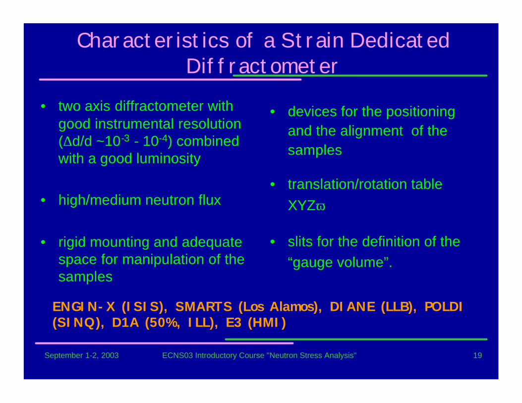
Characteristics of a Strain DedicatedDiffractometer
• two axis diffractometer withgood instrumental resolution(∆d/d ~10-3 - 10-4) combinedwith a good luminosity
• high/medium neutron flux
• rigid mounting and adequatespace for manipulation of thesamples
• devices for the positioningand the alignment of thesamples
• translation/rotation tableXYZω
• slits for the definition of the“gauge volume”.
ENGIN-X (ISIS), SMARTS (Los Alamos), DIANE (LLB), POLDI(SINQ), D1A (50%, ILL), E3 (HMI)

September 1-2, 2003 ECNS03 Introductory Course "Neutron Stress Analysis" 20
Spallation Source
tt∆
=λλ∆
=ε • good gauge volume definition
• Diffraction angle fixed, wavelength varies
• Peaks from many planes recordedsimultaneously
• Useful for anisotropic systems
September 1-2, 2003 ECNS03 Introductory Course "Neutron Stress Analysis" 21
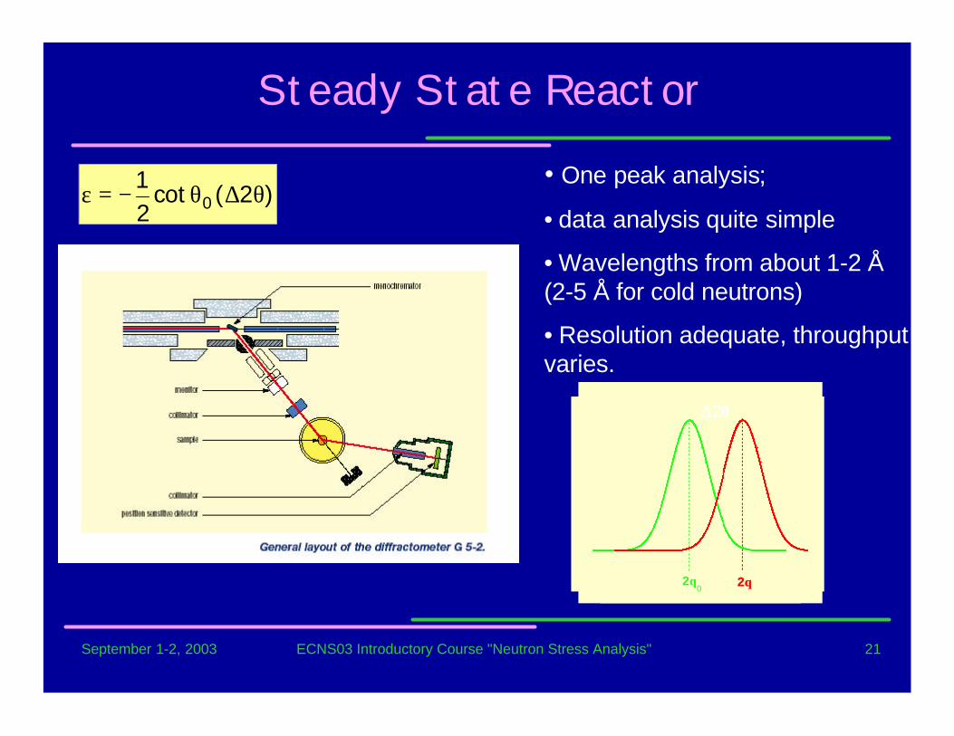
2θ0
2θ
∆2θ
Steady State Reactor
• One peak analysis;
• data analysis quite simple
• Wavelengths from about 1-2 Å(2-5 Å for cold neutrons)
• Resolution adequate, throughputvaries.
)2(cot21
0 θ∆θ−=ε
2θ0
2θ
∆2θ
September 1-2, 2003 ECNS03 Introductory Course "Neutron Stress Analysis" 22
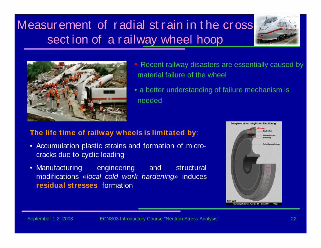
Measurement Measurement of radial of radial strain strain in in the the crosscrosssection of a section of a railway wheel hooprailway wheel hoop
• Recent railway disasters are essentially caused bymaterial failure of the wheel
• a better understanding of failure mechanism isneeded
The life time of railway wheels is limitated by:
• Accumulation plastic strains and formation of micro-cracks due to cyclic loading
• Manufacturing engineering and structuralmodifications «local cold work hardening» inducesresidual stresses formation

September 1-2, 2003 ECNS03 Introductory Course "Neutron Stress Analysis" 23
Strain Scanning
• Diffractomètre G52, λ = 3A
• Fe-α (110)
• résolution spatiale: 2x2x10 mm3
0,1
1
10
100
1000
0 5 10 15 20 25depth in mm
coun
ting
rate
of t
he 1
10 --
re
flexi
on in
cps
MaterialMaterial:: • perlitic steel
• Sector (35°) of an ICE train
• used 1.400.000 Km (life limit)
September 1-2, 2003 ECNS03 Introductory Course "Neutron Stress Analysis" 24
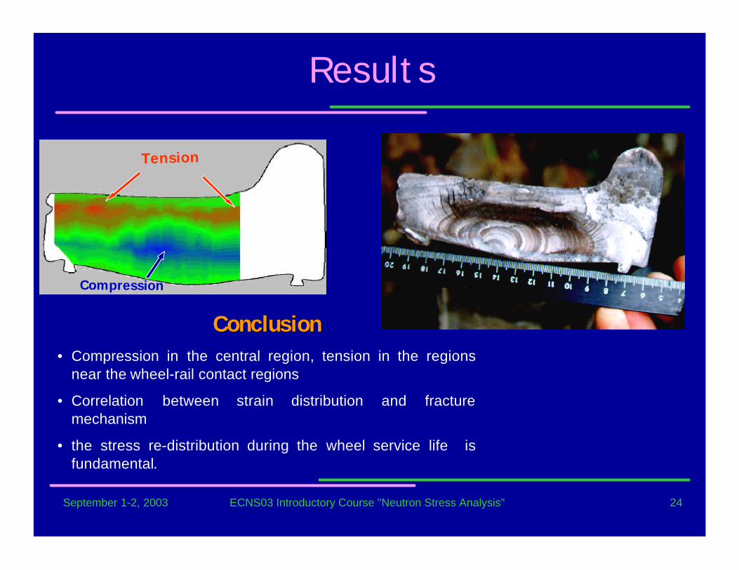
Results
Tension
Compression
ConclusionConclusion• Compression in the central region, tension in the regions
near the wheel-rail contact regions
• Correlation between strain distribution and fracturemechanism
• the stress re-distribution during the wheel service life isfundamental.
September 1-2, 2003 ECNS03 Introductory Course "Neutron Stress Analysis" 25
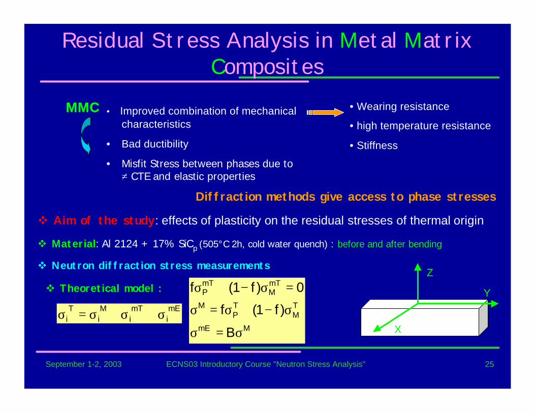
Residual Stress Analysis in Metal MatrixComposites
MMC
Diffraction methods give access to phase stresses
• Wearing resistance
• high temperature resistance
• Stiffness
• Improved combination of mechanicalcharacteristics
• Bad ductibility
• Misfit Stress between phases due to≠ CTE and elastic properties
MMC
v Aim of the study: effects of plasticity on the residual stresses of thermal origin
v Material: Al 2124 + 17% SiCp (505°C 2h, cold water quench) : before and after bending
mEi
mTi
Mi
Ti σ+σ+σ=σ
MmE
TM
TP
M
mTM
mTP
B
)f1(f
0)f1(f
σ=σ
σ−+σ=σ
=σ−+σv Theoretical model :
v Neutron diffraction stress measurements
X
Y
Z
September 1-2, 2003 ECNS03 Introductory Course "Neutron Stress Analysis" 26
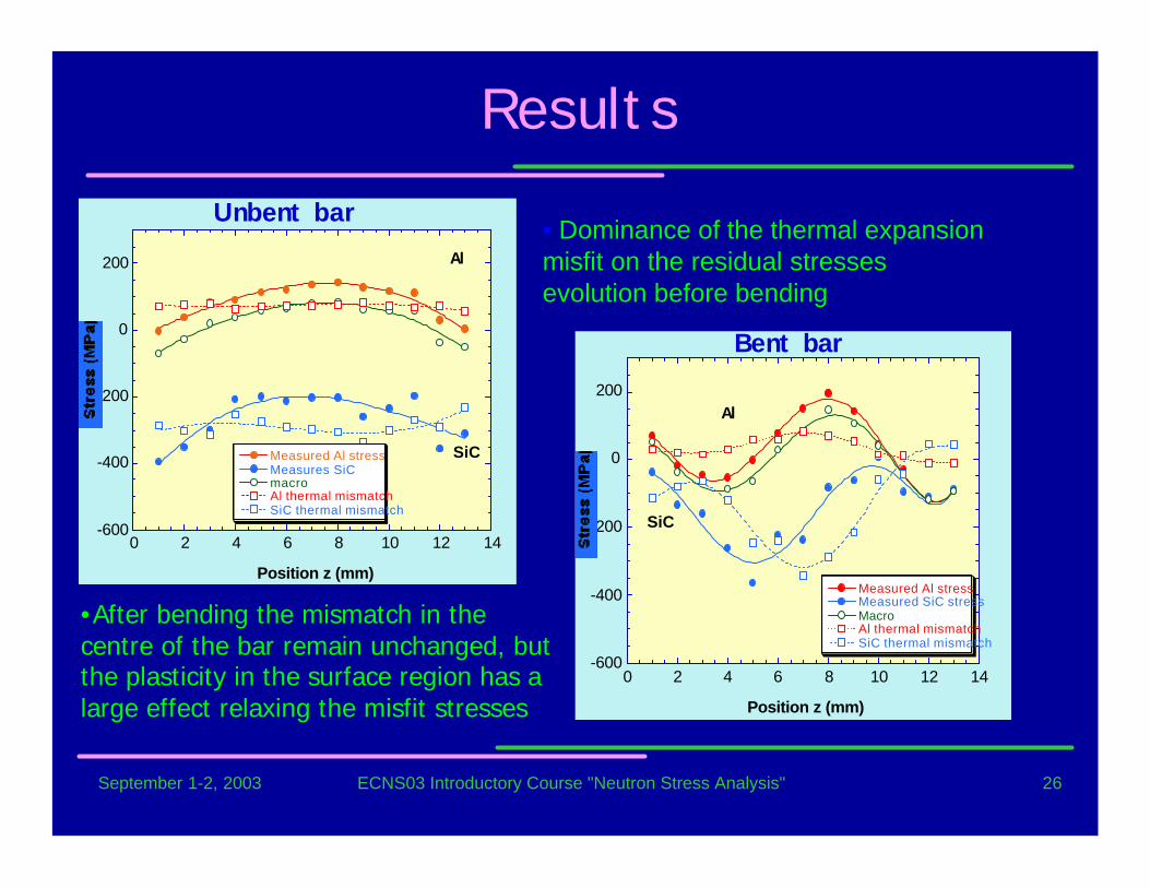
Results
-600
-400
-200
0
200
0 2 4 6 8 10 12 14
Measured Al stressMeasures SiC macroAl thermal mismatchSiC thermal mismatch
Position z (mm)
Al
SiC
Unbent bar• Dominance of the thermal expansionmisfit on the residual stressesevolution before bending
-600
-400
-200
0
200
0 2 4 6 8 10 12 14
Measured Al stressMeasured SiC stressMacroAl thermal mismatchSiC thermal mismatch
Position z (mm)
Al
SiC
Bent bar
•After bending the mismatch in thecentre of the bar remain unchanged, butthe plasticity in the surface region has alarge effect relaxing the misfit stresses

September 1-2, 2003 ECNS03 Introductory Course "Neutron Stress Analysis" 27
Residual Stresses and MicrostrainInvestigation in Fatigued Specimen
PLASTICREGION
CRACK
70 mm
10 mm
45 mm
AISI 316LCompact Tension specimens
• CT_1: R=0.1, 26000 cycles ∆K=30.48MPa mm 1/2
• CT_2: R=0.5, 20000 cycles ∆K=30.48MPa mm 1/2
• CT_3: tension up to 5mm crack opening(10000N)

September 1-2, 2003 ECNS03 Introductory Course "Neutron Stress Analysis" 28
Internal Elastic Stresses by NeutronDiffraction and FE calculation
-400
0
400
800
1200
-2 0 2 4 6 8 10 12 14 16 18
Str
ess
(MP
a)
Distance from the crack tip (mm)
crack tip
σxxσ
yy
σzz
-400
0
400
800
1200
-2 0 2 4 6 8 10 12 14 16 18
Str
ess
(MP
a)
Distance from the crack tip (mm)
crack tip
σxxσ
yy
σzz
Neutrons�q 3D measurements
�q Spatial resolution:
1x1x1 mm3
FE calculation• 3D
• Elastic-plastic behaviour
o In all the three specimens a 3D stress stateis observed.
o CT_1: the residual stresses obtained arerather weak.
o CT_2: higher tensile stresses with amaximum at 1.5 mm from the crack tip.
o CT_3: the maximum stress level is at 2 mmfrom the tip. At 8mm from the tip, σxx and σyyare very low, whereas σzz becomes large andcompressive
September 1-2, 2003 ECNS03 Introductory Course "Neutron Stress Analysis" 29
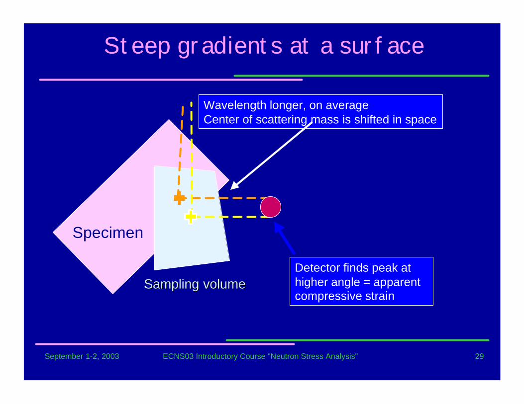
Steep gradients at a surface
Detector finds peak athigher angle = apparentcompressive strain
Wavelength longer, on averageCenter of scattering mass is shifted in space
Sampling volumeSampling volume
Specimen
September 1-2, 2003 ECNS03 Introductory Course "Neutron Stress Analysis" 30
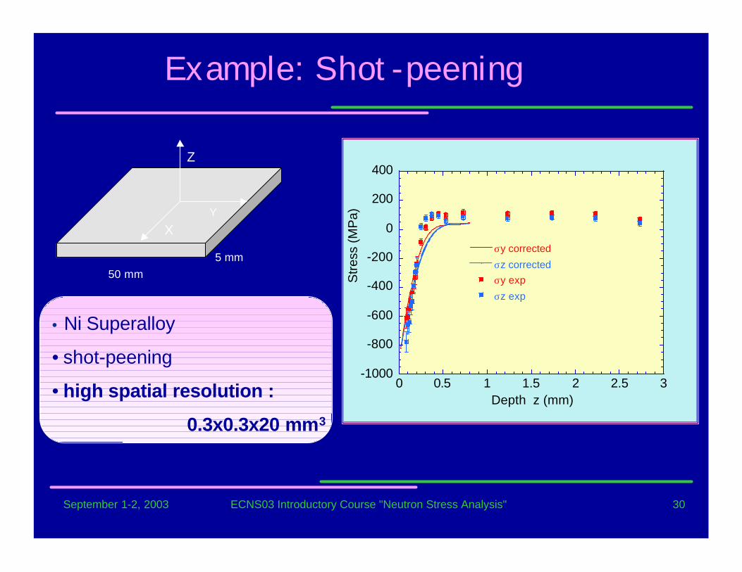
Z
Y
X
50 mm5 mm
• Ni Superalloy
• shot-peening
• high spatial resolution :
0.3x0.3x20 mm3
-1000
-800
-600
-400
-200
0
200
400
0 0.5 1 1.5 2 2.5 3
σy corrected
σz correctedσy exp
σz exp
Depth z (mm)
Stre
ss (M
Pa)
Example: Shot-peening
September 1-2, 2003 ECNS03 Introductory Course "Neutron Stress Analysis" 31
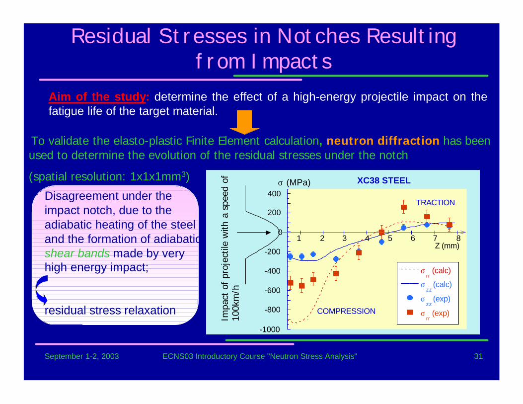
Residual Stresses in Notches Resultingfrom Impacts
Aim of the study: determine the effect of a high-energy projectile impact on thefatigue life of the target material.
To validate the elasto-plastic Finite Element calculation, neutron diffraction has beenused to determine the evolution of the residual stresses under the notch
(spatial resolution: 1x1x1mm3)
-1000
-800
-600
-400
-200
0
200
400
1 2 3 4 5 6 7 8
σrr (calc)
σzz
(calc)
σzz
(exp)
σrr (exp)
Z (mm)
σ (MPa)
COMPRESSION
TRACTION
XC38 STEEL
Impa
ct o
f pr
ojec
tile
with
a s
peed
of
100k
m/h
Disagreement under theimpact notch, due to theadiabatic heating of the steeland the formation of adiabaticshear bands made by veryhigh energy impact;
residual stress relaxation
September 1-2, 2003 ECNS03 Introductory Course "Neutron Stress Analysis" 32
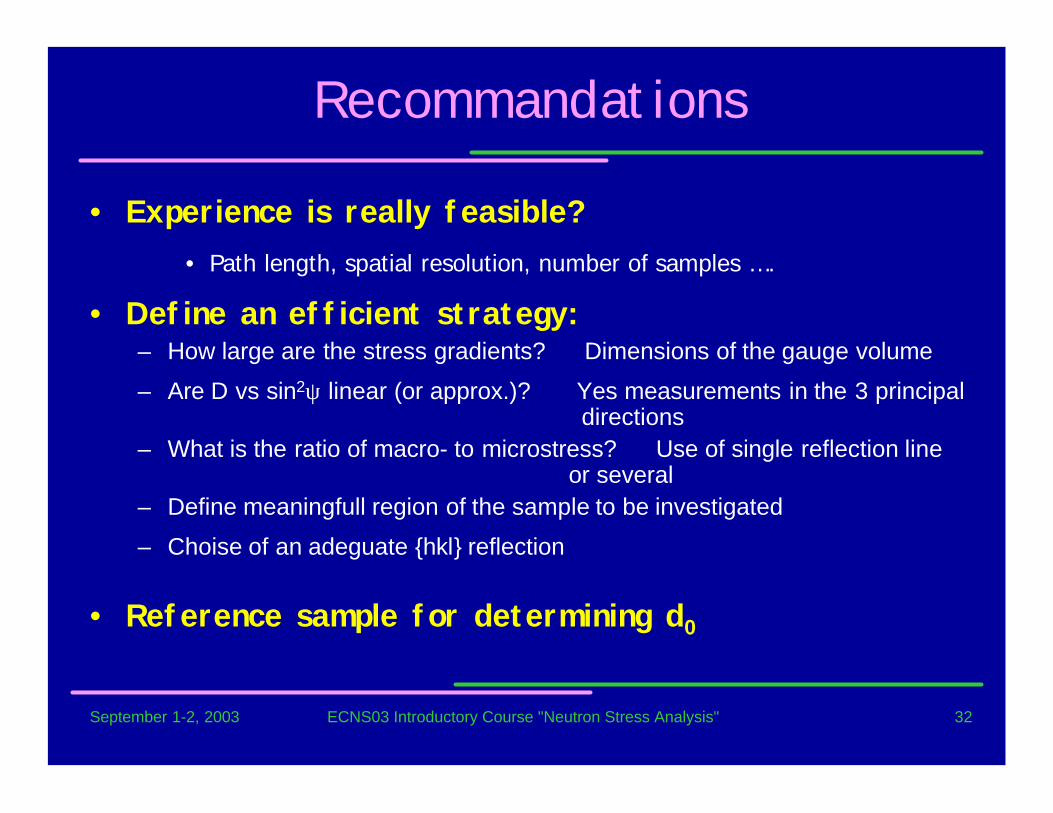
Recommandations
• Experience is really feasible?• Path length, spatial resolution, number of samples ….
• Define an efficient strategy:– How large are the stress gradients? Dimensions of the gauge volume
– Are D vs sin2ψ linear (or approx.)? Yes measurements in the 3 principal directions
– What is the ratio of macro- to microstress? Use of single reflection line or several
– Define meaningfull region of the sample to be investigated
– Choise of an adeguate {hkl} reflection
• Reference sample for determining d0
September 1-2, 2003 ECNS03 Introductory Course "Neutron Stress Analysis" 33
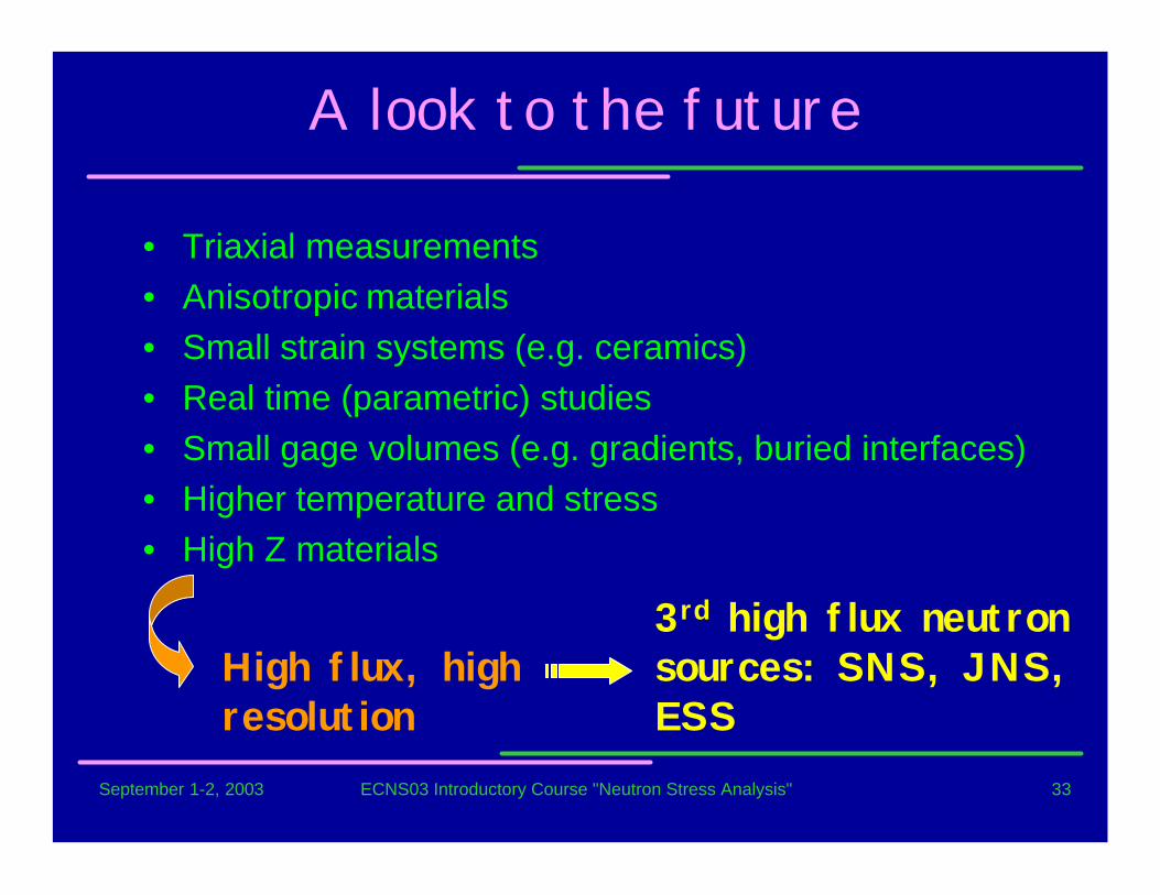
A look to the future
• Triaxial measurements• Anisotropic materials• Small strain systems (e.g. ceramics)• Real time (parametric) studies• Small gage volumes (e.g. gradients, buried interfaces)• Higher temperature and stress• High Z materials
High flux, highresolution
3rd high flux neutronsources: SNS, JNS,ESS
September 1-2, 2003 ECNS03 Introductory Course "Neutron Stress Analysis" 34
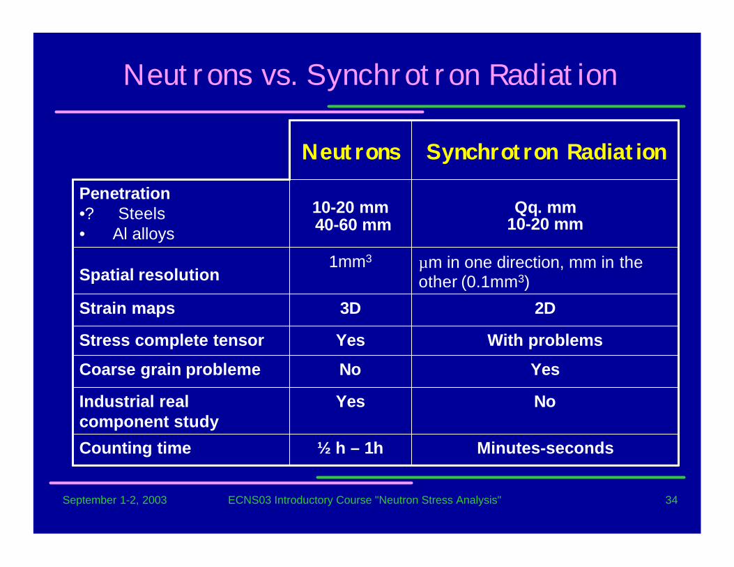
Neutrons vs. Synchrotron Radiation
Minutes-seconds½ h – 1hCounting time
NoYesIndustrial realcomponent study
YesNoCoarse grain probleme
With problemsYesStress complete tensor
2D3DStrain maps
µm in one direction, mm in theother (0.1mm3)
1mm3
Spatial resolution
Qq. mm 10-20 mm
10-20 mm 40-60 mm
Penetration•? Steels• Al alloys
Synchrotron RadiationNeutrons


![RESIDUAL STRESS MEASUREMENTS BY NEUTRON …3 Residual stress measurements by neutron diffraction at the IBR-2 pulsed reactor 493 strains along different [hkl] directions simultaneously,](https://img.pdfslide.net/doc/110x75/60de95aa68163e53d2609032/residual-stress-measurements-by-neutron-3-residual-stress-measurements-by-neutron.jpg)