Embed Size (px)
Citation preview
New design of robust industrialaccumulators for elastic webs
David KUHM ∗,∗∗∗ Dominique KNITTEL ∗,∗∗
∗Web Handling Research Group, University of Strasbourg, 17, rue duMarechal Lefebvre, 67100 Strasbourg, France (Corresponding author:
[email protected]).∗∗ Laboratoire de Genie de la Conception INSA Strasbourg,
24, boulevard de la Victoire, 67084 Strasbourg, France∗∗∗ Laboratoire de Physique et Mecanique Textiles ENSISA,
11, rue Alfred Werner, 68093 Mulhouse, France
Abstract: This paper concerns the modelling of an accumulator used in an industrial elasticweb processing plant (paper, fabric, polymer, metal ...). Accumulators are used to allow unwindor rewind roll changes while the rest of the line remains at a constant web velocity. Detailednonlinear models of industrial accumulators are first given. The first one is a pneumaticactuated accumulator, the second one is motor actuated. These models are derived from thephysical relationships that describe web tension and velocity dynamics in each web span ofthe accumulator. In a second part, control strategies are detailed. Industrial PI controllers,tuned with evolutionary algorithm on our realistic non-linear model, are presented, allowinggood robustness against mechanical parameter variations. In this part the motor actuatedaccumulator performances are enhanced by including a dancer.
Keywords: Roll to roll systems, Accumulator, Modelling, Control, Optimization, Simulation.
1. INTRODUCTION
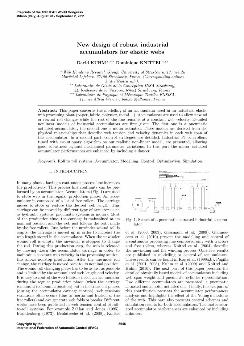
In many plants, having a continuous process line increasesthe productivity. This process line continuity can be per-formed by an accumulator. Accumulators (Fig. 1) are usedto store web in the regular production phase. An accu-mulator in composed of a lot of free rollers. The carriagemoves to store or restore the desired web length. Thiscarriage can be moved by different type of actuators suchas hydraulic systems, pneumatic systems or motors. Mostof the production time, the carriage is maintained at itsnominal position and the web just follows the path madeby the free rollers. Just before the unwinder wound roll isempty, the carriage is moved up in order to increase theweb length stored in the accumulator. When the unwinderwound roll is empty, the unwinder is stopped to changethe roll. During this production step, the web is releasedby moving down the accumulator carriage in order tomaintain a constant web velocity in the processing section,this allows nonstop production. After the unwinder rollchange, the carriage is moved back to its nominal position.The wound roll changing phase has to be as fast as possibleand is limited by the accumulated web length and velocity.It is easy to control the web tensions inside an accumulatorduring the regular production phase (when the carriageremains at its nominal position) but in the transient phases(during the accumulator carriage motion), web tensionsvariations often occurs (due to inertia and friction of thefree rollers) and can generate web folds or breaks. Differentworks have been published in web tension control of roll-to-roll systems. For example Zahlan and Jones (1995),Brandenburg (1973), Benlatreche et al. (2008), Knittel
Unwinder Welding table
1 n+1
Accumulator
...
Carriage
Pneumatic jack
Vin accu Vout accu
Tout
L
Fig. 1. Sketch of a pneumatic actuated industrial accumu-lator
et al. (2006, 2003), Gassmann et al. (2009), Giannoc-caro et al. (2010) present the modelling and control ofa continuous processing line composed only with tractorsand free rollers, whereas Knittel et al. (2004) describethe unwinding and the winding process. Only few resultsare published in modelling or control of accumulators.These results can be found in Koc et al. (1999a,b), Pagillaet al. (2001, 2003), Kuhm et al. (2009) and Knittel andKuhm (2010). The next part of this paper presents thedetailed physically based models of accumulators includingweb span weight and pneumatic cylinder representation.Two different accumulators are presented: a pneumaticactuated and a motor actuated one. Finally, the last part ofthis contribution presents the accumulator performancesanalysis and highlights the effect of the Young’s modulusof the web. This part also presents control schemes andsimulation results for both accumulators. The motor actu-ated accumulator performances are enhanced by includinga dancer.
Preprints of the 18th IFAC World CongressMilano (Italy) August 28 - September 2, 2011
Copyright by theInternational Federation of Automatic Control (IFAC)
8645
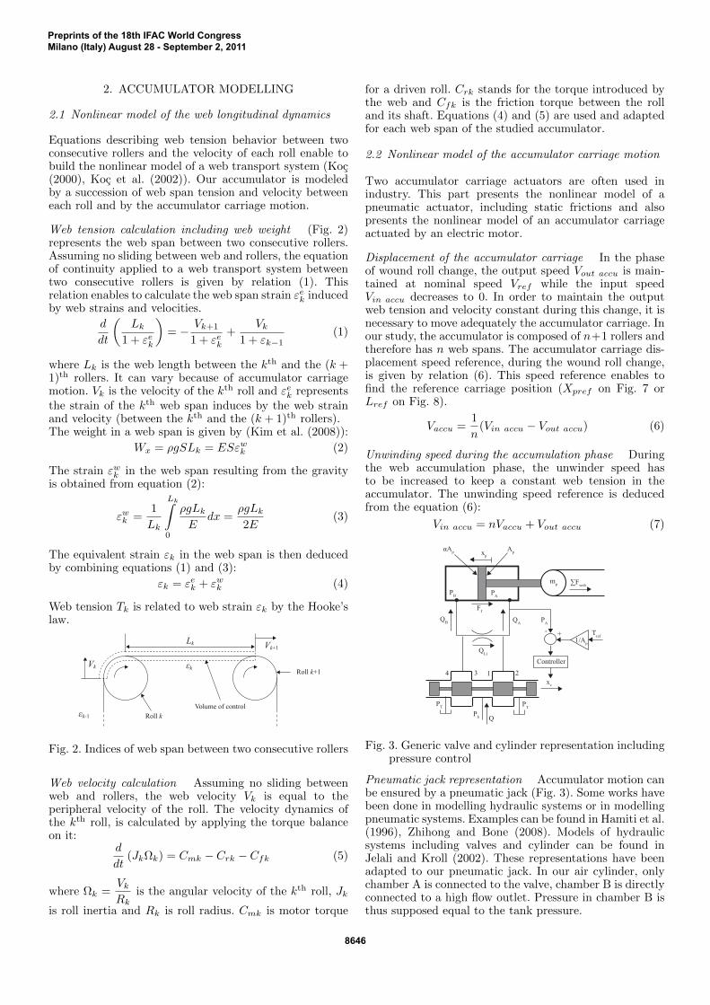
2. ACCUMULATOR MODELLING
2.1 Nonlinear model of the web longitudinal dynamics
Equations describing web tension behavior between twoconsecutive rollers and the velocity of each roll enable tobuild the nonlinear model of a web transport system (Koc(2000), Koc et al. (2002)). Our accumulator is modeledby a succession of web span tension and velocity betweeneach roll and by the accumulator carriage motion.
Web tension calculation including web weight (Fig. 2)represents the web span between two consecutive rollers.Assuming no sliding between web and rollers, the equationof continuity applied to a web transport system betweentwo consecutive rollers is given by relation (1). Thisrelation enables to calculate the web span strain εek inducedby web strains and velocities.
d
dt
(Lk
1 + εek
)= − Vk+1
1 + εek+
Vk1 + εk−1
(1)
where Lk is the web length between the kth and the (k +1)th rollers. It can vary because of accumulator carriagemotion. Vk is the velocity of the kth roll and εek representsthe strain of the kth web span induces by the web strainand velocity (between the kth and the (k + 1)th rollers).The weight in a web span is given by (Kim et al. (2008)):
Wx = ρgSLk = ESεwk (2)
The strain εwk in the web span resulting from the gravityis obtained from equation (2):
εwk =1
Lk
Lk∫0
ρgLk
Edx =
ρgLk
2E(3)
The equivalent strain εk in the web span is then deducedby combining equations (1) and (3):
εk = εek + εwk (4)
Web tension Tk is related to web strain εk by the Hooke’slaw.
Vk+1
Vk
Lk
εk
εk-1 Volume of control
Roll k+1
Roll k
Fig. 2. Indices of web span between two consecutive rollers
Web velocity calculation Assuming no sliding betweenweb and rollers, the web velocity Vk is equal to theperipheral velocity of the roll. The velocity dynamics ofthe kth roll, is calculated by applying the torque balanceon it:
d
dt(JkΩk) = Cmk − Crk − Cfk (5)
where Ωk =VkRk
is the angular velocity of the kth roll, Jk
is roll inertia and Rk is roll radius. Cmk is motor torque
for a driven roll. Crk stands for the torque introduced bythe web and Cfk is the friction torque between the rolland its shaft. Equations (4) and (5) are used and adaptedfor each web span of the studied accumulator.
2.2 Nonlinear model of the accumulator carriage motion
Two accumulator carriage actuators are often used inindustry. This part presents the nonlinear model of apneumatic actuator, including static frictions and alsopresents the nonlinear model of an accumulator carriageactuated by an electric motor.
Displacement of the accumulator carriage In the phaseof wound roll change, the output speed Vout accu is main-tained at nominal speed Vref while the input speedVin accu decreases to 0. In order to maintain the outputweb tension and velocity constant during this change, it isnecessary to move adequately the accumulator carriage. Inour study, the accumulator is composed of n+1 rollers andtherefore has n web spans. The accumulator carriage dis-placement speed reference, during the wound roll change,is given by relation (6). This speed reference enables tofind the reference carriage position (Xpref on Fig. 7 orLref on Fig. 8).
Vaccu =1
n(Vin accu − Vout accu) (6)
Unwinding speed during the accumulation phase Duringthe web accumulation phase, the unwinder speed hasto be increased to keep a constant web tension in theaccumulator. The unwinding speed reference is deducedfrom the equation (6):
Vin accu = nVaccu + Vout accu (7)
PAPB
QLi
mp
xv
PT PT
PS Q
QAQB
∑Fweb
Ff
xpApαAp
1 234
PA
- + Tref
Controller
1/Ap
Fig. 3. Generic valve and cylinder representation includingpressure control
Pneumatic jack representation Accumulator motion canbe ensured by a pneumatic jack (Fig. 3). Some works havebeen done in modelling hydraulic systems or in modellingpneumatic systems. Examples can be found in Hamiti et al.(1996), Zhihong and Bone (2008). Models of hydraulicsystems including valves and cylinder can be found inJelali and Kroll (2002). These representations have beenadapted to our pneumatic jack. In our air cylinder, onlychamber A is connected to the valve, chamber B is directlyconnected to a high flow outlet. Pressure in chamber B isthus supposed equal to the tank pressure.
Preprints of the 18th IFAC World CongressMilano (Italy) August 28 - September 2, 2011
8646
Pressure/flow equation for a valve A valve comport lot ofnon linearities such as dead band, saturations, hysteresis,friction forces. The air flow across the valve is representedby relations (8) and (9). (Jelali and Kroll (2002))
QA = Cv1.sg(xv).sign(PS − PA).√|PS − PA|
−Cv2.sg(−xv).sign(PA − PT ).√|PA − PT |
(8)
QB = Cv3.sg(−xv).sign(PS − PB).√|PS − PB |
−Cv4.sg(xv).sign(PB − PT ).√|PB − PT |
(9)
with
sg(xv) =
xv for xv ≥ 00 for xv < 0
(10)
sg(−xv) =
−xv for − xv ≥ 0
0 for − xv < 0(11)
where xv determines air flow direction. Cvi are the valveorifice coefficients.
Dynamic representation of the servo-valve The dynamicof a servo valve is given by (Jelali and Kroll (2002)):
1
ω2v
xv +2Dv
ωvxv + xv + fhs.sign(xv) = Kv.uv (12)
where xv denotes the valve position. Kv is the valve gain,wv is the valve natural frequency, Dv is the valve dampingcoefficient and fhs is the valve hysteresis. These coefficientsare often given by valves manufacturers.
Pressure dynamics in cylinder chamber The air cylinderalso presents non linearities such as pressure dependentbulk modulus, saturations, friction forces. Air flow insideeach cylinder chamber is represented according to relations(13) and (14) (Jelali and Kroll (2002)):
QA −QLi = VA +VA
E′(PA)PA (13)
QB +QLi = ˙VB +VB
E′(PB)PB (14)
VA = VP1A +
(S
2+ xp
)AP (15)
VB = VP1B +
(S
2− xp
)αAP (16)
VA = AP xp (17)
˙VB = −αAP xp (18)
with VA and VB the volume of each chamber, includingthe valve connecting line. QLi represents the internal flowleakage between the two chambers. VP1A and VP1B are thepipeline volumes, S is the piston stroke, AP is the pistonsurface, α is the ratio between chamber A and chamberB piston surface. E′(PA) and E′(PB) are the effectivebulk modulus depending on the pressure. xp, the pistonposition, allows to deduce the web span length. Finalyfrom relations (13) to (18) the pressure dynamics into eachcylinder chamber is then given by:
PA =E′(PA)
VA(QA −APxp −QLi) (19)
PB =E′(PB)
VB(QB + αAPxp +QLi) (20)
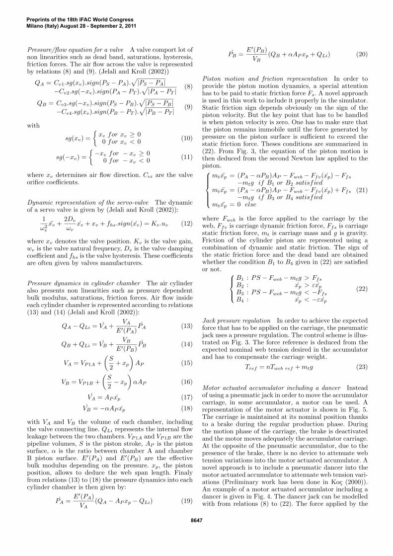
Piston motion and friction representation In order toprovide the piston motion dynamics, a special attentionhas to be paid to static friction force Fs. A novel approachis used in this work to include it properly in the simulator.Static friction sign depends obviously on the sign of thepiston velocity. But the key point that has to be handledis when piston velocity is zero. One has to make sure thatthe piston remains immobile until the force generated bypressure on the piston surface is sufficient to exceed thestatic friction force. Theses conditions are summarized in(22). From Fig. 3, the equation of the piston motion isthen deduced from the second Newton law applied to thepiston.
mtxp = (PA − αPB)AP − Fweb − Ffv(xp)− Ffs
−mtg if B1 or B2 satisfiedmtxp = (PA − αPB)AP − Fweb − Ffv(xp) + Ffs
−mtg if B3 or B4 satisfiedmtxp = 0 else
(21)
where Fweb is the force applied to the carriage by theweb, Ffv is carriage dynamic friction force, Ffs is carriagestatic friction force, mt is carriage mass and g is gravity.Friction of the cylinder piston are represented using acombination of dynamic and static friction. The sign ofthe static friction force and the dead band are obtainedwhether the condition B1 to B4 given in (22) are satisfiedor not.
B1 : PS − Fweb −mtg > Ffs
B2 : xp > εxpB3 : PS − Fweb −mtg < −Ffs
B4 : xp < −εxp
(22)
Jack pressure regulation In order to achieve the expectedforce that has to be applied on the carriage, the pneumaticjack uses a pressure regulation. The control scheme is illus-trated on Fig. 3. The force reference is deduced from theexpected nominal web tension desired in the accumulatorand has to compensate the carriage weight.
Tref = nTweb ref +mtg (23)
Motor actuated accumulator including a dancer Insteadof using a pneumatic jack in order to move the accumulatorcarriage, in some accumulator, a motor can be used. Arepresentation of the motor actuator is shown in Fig. 5.The carriage is maintained at its nominal position thanksto a brake during the regular production phase. Duringthe motion phase of the carriage, the brake is deactivatedand the motor moves adequately the accumulator carriage.At the opposite of the pneumatic accumulator, due to thepresence of the brake, there is no device to attenuate webtension variations into the motor actuated accumulator. Anovel approach is to include a pneumatic dancer into themotor actuated accumulator to attenuate web tension vari-ations (Preliminary work has been done in Koc (2000)).An example of a motor actuated accumulator including adancer is given in Fig. 4. The dancer jack can be modelledwith from relations (8) to (22). The force applied by the
Preprints of the 18th IFAC World CongressMilano (Italy) August 28 - September 2, 2011
8647

Motor
Unwinder Welding table
1 n+1
Accumulator
...
Chains
PneumaticJack
Dancer
Carriage
...
Vin accu Vout accu
Tout
L
Fig. 4. Example of a motor actuated accumulator includinga pneumatic dancer
dancer is deduced from relation (23). The equation of thecarriage motion is deduced by applying a torque balanceon the carriage motor (24). The carriage position xc isrelated to wm by the radius of the motor/chain gear Rm.Friction forces are represented in the same way as for thepneumatic jack.
Jmwm = udmkdm−Rm(Fweb + Ffv(x)± Ffs +mtg)−Ffvmwm
(24)
with Jm is the motor inertia, udm is the reference voltage,kdm is the ratio from reference voltage to torque, Fweb isthe force applied to the carriage by the web and Ffvm is themotor dynamic friction force. The accumulator carriagemotor is position controlled in order to move the carriageto the desired position. The control scheme is given inFig. 5.
mc
∑Fweb
Chain
Motor
Carriage
Rm
xc
FfMtg
Cm
-
+
Xref
Controller
Fig. 5. Generic motor representation including positioncontrol
2.3 State space representation of the accumulator
The linear model is deduced from the nonlinear one, andcan be described by a state space representation (25). Thestates are the tension and velocity in each web span. Thelinear model is obtained by linearizing an accumulatorincluding an ”ideal” carriage actuator (neglecting staticfriction and dead band). The linear model is useful forBode diagrams calculation. The state space model has treeinputs u+ v and one output Tn+1 the accumulator outputtension. The input u is the carriage displacement velocity,Vd is the unwinder speed. X =
(A+
A1
L
)X +
B
Lu+B1v
Y = CX +Du(25)
where
X = [ Td Va Ta Va1 Ta1 . . . Vn+1 Tn+1 ]T
v =
[Vd
Vout accu
]u =
dL
dt
(26)
3. ACCUMULATOR PERFORMANCES ANALYSISAND CONTROL
3.1 Influence of the mechanical parameters
Depending on the type of accumulator, mainly two controlstrategies are applied: one using Vin accu as control signal(controller output), the other using L. Using this controlstrategies let appears two transfer functions that can bestudied in the accumulator: a first one between the accu-mulator output tension Tout and the accumulator inputvelocity Vin accu named W1 and a second one betweenTout and the web span length L named W2. In the follow-ing part, the influence of the Young’s modulus variationsaround it’s nominal value is analyzed on simulated Bodediagrams.
Influence of elasticity modulus Web elasticity influencesthe web dynamics (tension and velocity) in the transientphases. One can observe in Fig. 6 that the static gainand resonances (gains and frequencies) are depending onthe Young’s modulus. The same observation have beenmade both transfer functions W1 and W2. Very often inthe industry, Young’s modulus changes occur during themanufacturing process. Therefore the accumulator perfor-mances have to be guaranteed in spit of web elasticityvariations. Consequently, the controllers have to be ad-justed/calculated for each value of web elasticity, or robustfor a given web elasticity range.
101 102 1030
50
100
150
Frequency (rad/sec)
Mag
nitu
de (d
B)
E0
E0/5
E0*5
Fig. 6. Bode diagram of W2 for different Young’s modulus
Remarks Other parameters variations can affect theaccumulator performances (Kuhm et al. (2009)). Web spanlength in the accumulator has a significant influence on theweb dynamics. Free rollers inertia also influences the webdynamics.
3.2 Control strategy
Control structure As mentioned previously in this paper,the accumulator can be controlled in two different ways:the controller can operate either on the web span length orthe input velocity. An output web tension controller can besynthesized by using the input velocity of the accumulatoras control signal. The second control strategy uses the weblength (by moving the accumulator carriage) as controlsignal. In industrial applications, both control schemes areused.
Preprints of the 18th IFAC World CongressMilano (Italy) August 28 - September 2, 2011
8648
Pneumatic actuated accumulator For the pneumatic ac-tuated accumulator, we use the input velocity of the accu-mulator as control signal. During the regular productionphase, we use the input velocity as actuator and during thewound roll change there is no control, the web just movesthe carriage by itself. The on/off continuous switchingstrategy of the controller is performed by weighting thecontroller output with a coefficient decreasing from 1 to 0.The control scheme is given in Fig. 7.
Accumulator
C1
Switching on/off strategy
Vref
Vin accu
Voutaccu
Xp ref + ++
Xp
Tout
Tref
Fig. 7. Pneumatic actuated accumulator control scheme
Motor actuated accumulator For the motor actuated ac-cumulator, we used a combination of the two strategies.During the regular production phase, we use the inputvelocity as actuator and during the wound roll change weuse the web length as actuator. The switching strategybetween the two controllers is performed by weighting thecontrollers output by a coefficient between 0 and 1. Thecontrol scheme is given in Fig. 8.
Accumulator
C1
Controller switchingstrategy
C2
Vref
Lref
Vin accu
Vout accu Tout
L
Tref +
++
+-
Fig. 8. Motor actuated accumulator control scheme
Controller optimization methods The PI controllers areoptimized using a multi-objective evolutionary algorithm.Evolutionary algorithm are used due to a lot of nonlin-earities in our system. The controllers also have to becalculated for a time-varying web length. A first costfunction, J1 uses the ITAE criterion to ensure a goodreference tracking. The second cost function J2 has thefollowing form:
J2 = θE − θE+∆E (27)
where θi is the IAE criterion applied to the shell of thesystem error signal for a Young’s modulus equal to i. Usingthe shell of the error signal instead of the error signalis a new method to compare performances if parametersvariations occurs. It focus only on the amplitude of thetension variations, regardless the number and frequency ofthe oscillations. J2 allows to find more robust controllers.The third and fourth cost function, J3 and J4, are theminimum and the maximum of the error signal and allowto limit high tension pikes.
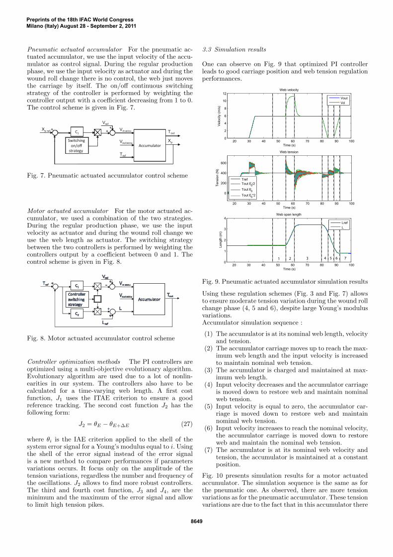
3.3 Simulation results
One can observe on Fig. 9 that optimized PI controllerleads to good carriage position and web tension regulationperformances.
20 30 40 50 60 70 80 90 100
0
200
400
600
Web tension
Time (s)
Tens
ion
(N)
TrefTout E0/2
Tout E0Tout E0*2
20 30 40 50 60 70 80 90 1000
2
4
6
8
10
12Web velocity
Time (s)
Vel
ocity
(m/s
)
VoutVd
20 30 40 50 60 70 80 90 1000
1
2
3
4Web span length
Time (s)
Leng
th (m
)LrefL
1 2 3 4 5 6 7
Fig. 9. Pneumatic actuated accumulator simulation results
Using these regulation schemes (Fig. 3 and Fig. 7) allowsto ensure moderate tension variation during the wound rollchange phase (4, 5 and 6), despite large Young’s modulusvariations.Accumulator simulation sequence :
(1) The accumulator is at its nominal web length, velocityand tension.
(2) The accumulator carriage moves up to reach the max-imum web length and the input velocity is increasedto maintain nominal web tension.
(3) The accumulator is charged and maintained at max-imum web length.
(4) Input velocity decreases and the accumulator carriageis moved down to restore web and maintain nominalweb tension.
(5) Input velocity is equal to zero, the accumulator car-riage is moved down to restore web and maintainnominal web tension.
(6) Input velocity increases to reach the nominal velocity,the accumulator carriage is moved down to restoreweb and maintain the nominal web tension.
(7) The accumulator is at its nominal web velocity andtension, the accumulator is maintained at a constantposition.
Fig. 10 presents simulation results for a motor actuatedaccumulator. The simulation sequence is the same as forthe pneumatic one. As observed, there are more tensionvariations as for the pneumatic accumulator. These tensionvariations are due to the fact that in this accumulator there
Preprints of the 18th IFAC World CongressMilano (Italy) August 28 - September 2, 2011
8649
0 10 20 30 40 50 60 70 80 90 100
0
200
400
600
800
Time (s)
Tens
ion
(N)
Web tension
TrefTout
1 2 3 4 5 6 7
Fig. 10. Motor actuated accumulator simulation results
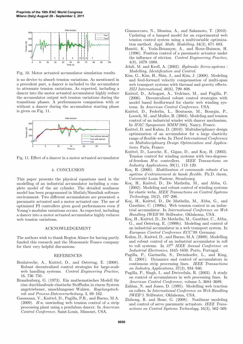
is no device to absorb tension variations. As mentioned ina precedent part, a dancer is included to the accumulatorto attenuate tension variations. As expected, including adancer into the motor actuated accumulator highly reducethe accumulator output web tension variations during thetransitions phases. A performances comparison with orwithout a dancer during the accumulator starting phaseis given on Fig. 11.
0 5 10 15 20 25 30
0
200
400
600
Web tension
Time (s)
Tens
ion
(N)
Tout without dancerTout with dancerTref
Fig. 11. Effect of a dancer in a motor actuated accumulator
4. CONCLUSION
This paper presents the physical equations used in themodelling of an industrial accumulator including a com-plete model of the air cylinder. The detailed nonlinearmodel has been programmed in Matlab/Simulink softwareenvironment. Two different accumulators are presented: apneumatic actuated and a motor actuated one. The use ofoptimized PI controllers gives good performances even ifYoung’s modulus variations occurs. As expected, includinga dancer into a motor actuated accumulator highly reducesweb tension variations.
ACKNOWLEDGEMENT
The authors wish to thank Region Alsace for having partlyfunded this research and the Monomatic France companyfor their very helpful discussions.
REFERENCES
Benlatreche, A., Knittel, D., and Ostertag, E. (2008).Robust decentralized control strategies for large-scaleweb handling systems. Control Engineering Practice,16, 736–750.
Brandenburg, G. (1973). Ein mathematisches Modell fureine durchlaufende elastische Stoffbahn in einem Systemangetriebener, umschlungener Walzen. Regelungstech-nik und Prozess-Datenverarbeitung, 3, 69–162.
Gassmann, V., Knittel, D., Pagilla, P.R., and Bueno, M.A.(2009). H∞ unwinding web tension control of a stripprocessing plant using a pendulum dancer. In AmericanControl Conference. Saint-Louis, Missouri, USA.
Giannoccaro, N., Messina, A., and Sakamoto, T. (2010).Updating of a lumped model for an experimental webtension control system using a multivariable optimiza-tion method. Appl. Math. Modelling, 34(3), 671–683.
Hamiti, K., Voda-Besancon, A., and Roux-Buisson, H.(1996). Position control of a pneumatic actuator underthe influence of stiction. Control Engineering Practice,4(8), 1079–1088.
Jelali, M. and Kroll, A. (2002). Hydraulic Servo-systems :Modelling, Identification and Control.
Kim, G., Kim, H., Shin, J., and Kim, J. (2008). Modelingand feed-forward velocity compensation of multi-spanweb transport systems with thermal and gravity effects.ISIJ International, 48(6), 799–808.
Knittel, D., Arbogast, A., Vedrines, M., and Pagilla, P.(2006). Decentralized robust control strategies withmodel based feedforward for elastic web winding sys-tems. In American Control Conference. USA.
Knittel, D., Federlin, L., Boutaous, M., Bourgin, P.,Loesch, M., and Muller, B. (2004). Modeling and tensioncontrol of an industrial winder with dancer mechanism.In IFAC Symposium MMM’2004. Nancy, France.
Knittel, D. and Kuhm, D. (2010). Multidisciplinary designoptimization of an accumulator for a large elasticityrange of flexible webs. In Third International Conferenceon Multidisciplinary Design Optimization and Applica-tions. Paris, France.
Knittel, D., Laroche, E., Gigan, D., and Koc, H. (2003).Tension control for winding systems with two-degrees-of-freedom H∞ controllers. IEEE Transactions onIndustry Applications, 39(1), 113–120.
Koc, H. (2000). Modelisation et commande robuste d’unsysteme d’entrainement de bande flexible. Ph.D. thesis,Universite Louis Pasteur, Strasbourg.
Koc, H., Knittel, D., De Mathelin, M., and Abba, G.(2002). Modeling and robust control of winding systemsfor elastic webs. IEEE Transactions on Control SystemsTechnology, 10(2), 197–206.
Koc, H., Knittel, D., De Mathelin, M., Abba, G., andGauthier, C. (1999a). Web tension control in an indus-trial accumulator. In International Conference on WebHandling IWEB’99. Stillwater, Oklahoma, USA.
Koc, H., Knittel, D., De Mathelin, M., Gauthier, C., Abba,G., and Ostertag, E. (1999b). Modeling and control ofan industrial accumulator in a web transport system. InEuropean Control Conference ECC’99. Germany.
Kuhm, D., Knittel, D., and Bueno, M.A. (2009). Modellingand robust control of an industrial accumulator in rollto roll systems. In 35th IEEE Annual Conference onIndustrial Electronics, 1645–1650. Porto, Portugal.
Pagilla, P., Garimella, S., Dreinhoefer, L., and King,E. (2001). Dynamics and control of accumulators incontinuous strip processing lines. IEEE Transactionson Industry Applications, 37(3), 934–940.
Pagilla, P., Singh, I., and Dwivedula, R. (2003). A studyon control of accumulators in web processing lines. InAmerican Control Conference, volume 5, 3684–3689.
Zahlan, N. and Jones, D. (1995). Modelling web tractionon rollers. In International Conference on Web HandlingIWEB’3. Stillwater, Oklahoma, USA.
Zhihong, R. and Bone, G. (2008). Nonlinear modelingand control of servo pneumatic actuators. IEEE Trans-actions on Control Systems Technology, 16(3), 562–569.
Preprints of the 18th IFAC World CongressMilano (Italy) August 28 - September 2, 2011
8650