Embed Size (px)
Citation preview

RESEARCH MEMORANDUM INVESTIGATION OF HIGH -ANGLE -OF -ATTACK PERFORMANCE
OF A 14' RAMP-TYPE INLET IN VARIOUS
CIRCUMFERENTLAL BODY LOCATIONS
MACH NUMBER RANGE 1,5 TO 2.0
By Glenn A . Mitchell and Bruce G. Chiccine
Lewis Flight Propulsion Laboratory Cleveland, Ohio
CLASSIFIED DOCUMENT
This material contains Information affecting the National Defense of the United States within the meantng of the espionage laws, T l e 18, U.S.C., Secs. 793 and 794, the transmission or revelatioa of which in any manuer to an uuauthorfzed person is prohibited by law.
NATIONAL ADVISORY COMMITTEE FOR AERONAUTICS
https://ntrs.nasa.gov/search.jsp?R=19660024049 2018-07-20T16:12:06+00:00Z

NACA RM E57C12a COl!lFIDENTIAL
NATIONAL ADVISORY COMMITTEE FOR AERONAUTICS
RESEARCH MEMORANDUM
INVESTIGATION OF FIIGH-AI'lGI;E- OF -ATTACK PERFOWCE OF A 14' RAMP-TYPE
INL;ET IN VARIOUS CIRCUMFERENTIaL BODY LOCATIONS
MACH NlTMBER RANGE 1.5 TO 2.0
By Glenn A. Mitchell and Bruce G. Chiccine
SUMMARY
An experimental investigation to determine the internal flow per- formance of a fixed 14O ramp inlet from zero to 20' angle of attack was conducted at free-stream Mach numbers of 1.5, 1.8, and 2.0, The inlet was mounted in three circumferential fuselage locations and utilized in- let throat and fuselage boundary-layer removal.
Results indicate a superiority of a bottom inlet location over a side or top inlet location at angles of attack; relatively low pressure recoveries and high distortions were obtained with side and top inlets. Some improvement in side inlet performance was obtained with the use of flow deflector plates mounted at the top side of the inlet. Improve- ments in top inlet performance resulted from the substitution of a rounded approach for the original flat approach to the inlet. Distor- tion levels for these modifications to the original side and top inlet configurations remained prohibitively high. However, placing a canopy in front of the top inlet, although decreasing the performance at low angles of attack, improved pressure recovery and greatly reduced distor- tions at higher angles.
INTRODUCTION
Past research has shown that body crossflow phenomena and variable boundary-layer thickness along the circumference of a fuselage at angles of attack have significant effects on the angle-of-attack performance of an inlet in various circumferential locations (refs. 1 to 4). Specifi- cally, pressure recovery performance for bottom inlet locations was main- tained up to the highest angles of attack tested, 10' to 12O, whereas sizable reductions in pressure recovery were incurred by side and top inlets. The performance of these inlets was obtained with fuselage boundary-layer removal generally adequate for the case at zero angle of attack.

corn IDENT IAL
More recent investigations (such as r e f . 5) with a f t i n l e t s u t i l i z - ing fuselage boundary-layer removal have indicated increased performance a t zero angle of attack by bleeding off boundary layer i n the v i c in i ty of the i n l e t throat . With proper throat bleed t h i s performance gain could be maintained independently of the amount of fuselage boundary- layer removal. A s an extension of t h i s work, a study was conducted t o determine i f the beneficial e f fec ts of bleed could be extended t o the case of a f t i n l e t s a t angles of attack. A fixed 14' ramp i n l e t with fuselage and i n l e t throat boundary-layer removal was tested a l te rna te ly i n the bottom, side, and top positions on a body of revolution i n the 8- by 6-foot supersonic wind tunnel a t Mach numbers of 1.5, 1.8, and 2.0 and angles of attack from zero t o 20°.
A area, sq in .
A~ bleed minimum ex i t area, sq in .
i n l e t capture area, 19.51 sq i n .
At i n l e t throat area, 13.55 sq in .
A2 diffuser flow area a t model s ta t ion 85.0, 18.31 sq in .
A3 diffuser flow area a t model s ta t ion 99.2, 22.99 sq i n .
hydraulic diameter, 4A
wetted perimeter
h fuselage boundary-layer diverte'r height, in .
M Mach number
ma.in-duct mass flow "3Irn0 main-duct mass-flow ra t io ,
'ovoAi ~ ( m ~ / m ~ I s table range of mass-flow ra t io ,
(m3/mO)cr - (m3/mO)min s table
P t o t a l pressure
measured t o t a l pressure ( p i t o t pressure) a t boundary- layer survey s ta t ion
P2,max - '2,min total-pressure dis tor t ion
P2
P2,max - P2,min maximum total-pressure variation a t pressure rake a t model s t a t ion 85.0
CONFIDENTIAL

NACA E57C12a CONl?IDENTIAL
fuselage boundary-layer thickness at zero angle of attack (0.55 in. at model station 55.1)
velocity, ft/sec
weight flow per unit area, referenced to standard sea- level conditions, (lb/sec) (sq ft)
a angle of attack, deg
ratio of total pressure to NACA stanaard sea-level total pressure of 2116 -22 lb/sq ft
ratio of total temperature to NACA standard sen-level temperature of 518.688O R
P mass density
Subscripts :
cr critical
max maximum
min minimum
0 free stream
1 fuselage boundary-layer survey station, model station 55.1
2 diffuser total-pressure survey station, model station 85 .O
3 diffuser static-pressure survey station,.model ,station .99.2
APPARCLTUS AND PROCEDURE
A schematic drawing of the fuselage, inlet, and boundary-layer re- moval system of the bottom inlet configuration is presented in figure 1, and a photograph of the inlet appears in figure 2. Photographs of the side and top inlet configurations are shown in figures 3 and 4. The inlet-diffuser assembly was mounted, with one exception, on the flat side of a basic body-of-revolution consisting of an ogive nose and a 10-inch- diameter cylindrical afterbody aft of model station 46.2. For the

CONFIDENTIAL NACA RM E57C12a
exception ( f i g . 4(b)) t he f l a t was eliminated and t he i n l e t was mounted d i r e c t l y on t h e cy l i nd r i ca l body. I n t he other top i n l e t configura- t i ons ( f i g s . 4(a) and ( c ) ) t h e i n l e t was mounted on t he f l a t . The in - l e t cowl l i p f o r a l l configurations was located a t model s t a t i o n 61.9. Swept s ide f a i r i ngs , used on t h e i n l e t , extended from t h e cowl s ides t o t h e leading edge of t h e ramp.
Fuselage boundary-layer d ive r t e r height was varied with spacers inse r ted between t he body and t he in le t -d i f fuser i n s t a l l a t i o n . Two di- v e r t e r heights were investigated, 0.183 and 0.55 inch (h / t = 113 and 1). I n the top i n l e t configuration with t he i n l e t mounted on t he cy l indr ica l body, t he d ive r t e r height was 0.55 inch only on t he v e r t i c a l center plane. The d i f fuser reference l i n e was maintained p a r a l l e l t o the body ax i s a t a l l times.
Boundary layer enter ing t h e i n l e t of the bottom and s ide i n l e t con- f igura t ions w a s removed by a f l u s h s l o t located on t he compression ramp ins ide t h e i n l e t and extending from w a l l t o wall. Mass flow drawn through t h i s s l o t and dumped i n t o t h e bleed chamber was e jected through openings i n e i t h e r s i de of t h e i n l e t cowl. Variation i n bleed mass flow w a s accomplished by varying back pressure i n t he bleed chamber with e p a i r of remotely control led doors a t the bleed ex i t s .
Except f o r d e t a i l s of t he bleed system, the i n l e t w a s i den t i ca l t o t h a t reported i n reference 5. The f l u sh s l o t bleed system of reference 5 does not have a bleed chamber such a s shown i n f i gu re 1 but has a smoothly f a i r e d duct from t h e s l o t t o the bleed e x i t . The s l o t area of t h e present configuration was 4.48 square inches; t h a t of reference 5 was 4.25 square inches.
The top i n l e t configurations had, i n addi t ion t o t h e f l u sh s l o t , ramp perforat ions ly ing almost wholly forward of t he cowl l i p . The open a rea of t h e perforat ions was 2.5 square inches o r 18.4 percent of t he t h roa t area, and t he porosi ty of t h i s perforated area was 24 percent (hole d i m . , 0.07 in . ; p l a t e thickness, 0.12 i n . ) . Both t he f l u sh s l o t and t he perforat ions were open t o t h e same bleed chamber. I n an attempt t o provide add i t iona l bleed e x i t area, s l o t s were cut i n t o t he s ides of t h e ramp and vents were adtied as shown i n f i gu re 4 (a ) .
The flow def lec tor p l a t e s used with t h e s i de i n l e t ( f i g s . 3(b) and ( c ) ) were mounted 0.25 inch from the s ide of t he ramp and extended fo r - ward of t he ramp leading edge 3.64 and 8.39 inches o r 76 and 154 percent of t he i n l e t width f o r t he sho r t and long def lec tor p la tes , respect ively .
The d i f fu se r area var ia t ion i s shown i n f i gu re 5 . The a rea de- crease a t a point about 20 inches downstream of the cowl l i p i s due t o t h e presence of t he centerbody shown i n f i gu re 1.
CONFIDENTIAL

NACA RM E57C12a a CONFIDENTLAL
The model was connected directly to the support sting. Data were taken in two angle-of-attack ranges. Angle-of-attack data from zero to 8.6O were obtained with a straight sting; a skewed flange aft of the model was used to provide a range of angle of attack of 8.6O to 20°. Inlet mass flow was varied by means of a remotely controlled movable tailpipe plug attached to the sting.
The flow field ahead of the inlet was determined from a survey rake at model station 55.1. The average total pressure at %he diffuser exit was obtained from an area-weighted average of 32 total-pressure tubes located at station 85.0. The tubes were arranged in eight rakes equally spaced around the diffuser centerbody. The static-pressure orifices at station 85.0 were located both on the centerbody and the diffuser wall. Main duct mass-flow ratio was determined from the six static-pressure orifices (equally spaced around the diffuser wall) at station 99.2 and the known area ratio between that station and the exit plug where the flow was assumed to be choked.
Inlet stability was determined from oscillographs of a pressure transducer located in the diffuser at model station 85.0. The limit of stability, or the minimum stable point, of inlet operation was defined as a static-pressure pulsation with an amplitude of 5 percent of the diffuser total pressure.
The model was tested with the inlet in three circumferential loca- tions at angles of attack from zero to 20° and at free-stream Mach num- bers of 1.5, 1.8, and 2.0. The configurations investigated are listed in the following table:
CONFIDENTIAL
Fuselage diverter height parameter,
h/t
1, 113
1
1
1
1
al
1
a~alue of h measured at vertical center plane.
Side fairings
On
Off
Off
Off
On
On
On
t Configuration
Bottom inlet
Side inlet
Side inlet with short deflector plate
Side inlet with long deflector plate
Top inlet
Top inlet with rounded approach
Top inlet with canopy
Bleed system
Flush slot
Flush slot
Flush slot
Flush slot
Flush slot and ramp perf orations
Flush slot and ramp perforations
Flush slot and ramp perforations

CONFIDENTIAL NACA RM E57Cl2a
RESULTS AND DISCUSSION
Survey of Body Flow Field
Measured total-pressure profiles ahead of the inlet station for some of the configurations investigated are presented in figure 6. (The profiles shown in fig. 6(a) for a rounded approach on top of the body were obtained with the flat on the bottom of the body.) Outside of the boundary layer, flat or uniform profiles over the complete range of angle of attack were obtained only on the bottom of the body (fig. 6(b)). The Plat profiles obtained on the top of the body up to an angle of at- tack of 14O (fig. 6(a ) ) may be misleading in that variations in total pressure across the span of the inlet due to crossflow effects and boundary-layer thickening (ref. 2) coula affect the performance of an frrXet situated in this top position. Figures 6(c) and (d) show the de- ve~agment of low-energy regions on the side of the body leading to sep- aration at an angle of attack of about 20°.
Vmiation of boundary-layer thickness on the flat bottom of the fuselage wlth angle of attack is shown in figure 7 for free-stream Mach auaibers of 1.5, 1.8, and 2.0. The major decrease in boundary-layer thickness occurred at angles of attack between zero and €I0. At an angle of attack of 8' the boundary-layer thickness was about 55 percent of the thickness at zero angle of attack. The zero-angle-of-attack boundary- layer thickness of 0.55 inch was obtained from reference 5.
Bottom Inlet Configuration: Flush Slot Bleed and Inlet Side Fairings
Inlet performance characteristics (total-pres sure recovery and dis - tortions) at zero angle of attack for the bottom inlet withafull fuse- lage boundary-layer removal (h/t = 1) are presented in figure 8. The data are plotted as a function of the maiduct mass-flow ratio for sev- eral values of bleed exit area. Both total-pressure recovery and dis- tortion were improved by bleeding at the inlet throat as reported in reference 5. The pressure recovery levels of this configuration were smlar to those of the flush slot bleed configuration of reference 5. However, a rather large decrease in critical mass-flow ratio with in- creasing inlet throat bleed'was reportea in reference 5 while the pres- '
ent configuration exhibited only small decreases with bleed. Evidently, the present configuration had a very low supercritical flow coefficient through the bleed system. The similarity of performance of the two con- figurations suggests that the subcritical flow coefficients were about the same.
The angle-of-attack performance was obtained with a fixed bleed door position of A~,/& = 0.155 which corresponded to the value shown
. ,
C0rnDmIA.L

NACA RM E57C12a CONFIDENTIAL
in reference 5 to provide nearly optimum pressure recovery and thrust- minus-drag. Angle-of-attack performance for the bottom inlet configura- tion with a fuselage diverter height equal to the boundary-layer thick- ness at zero angle of attack is presented in figure 9(a). Peak pressure recovery at each free-stream Mach number varied only 2 percent over the range of angles of attack up to 20°. Reduction in peak recovery with angle of attack occurred only at a free-stream Mach number of 1.8, An increase in both peak and critical pressure recovery was observed at a free-stream Mach number of 2.0. Total-pressure distortions at critical mass-flow ratio were below 15 percent at angles of attack from zero to 200.
If the inlet was operated at the corrected weight flow which appears to give optimum performance at zero angle of attack (g = 25
at % = 2.0), angle-of -attack operation would make the inlet slightly
more subcritical. With this *type of inlet operation total-pressure re- covery would vary less than 2 percent and distortions would replain be- low 15 percent over the angle-of-attack range.
The range of stable mass-flow ratio increased with angle of attack. At a free-stream Mach number of 2.0 the range of stable mass-flowratio increased from 0.05 at zero angle of attack to at least 0.69 at an angle of attack of 20° (fig. 9(a) ) .
Reduction of the fuselage diverter height to one-third the boundary- layer thickness at zero angle of attack (fig. 9(b)) resulted in perform- ance that was practically identical to the performance of the inlet with complete boundary-layer removal. These da.ta corroborate somewhat those of reference 5 where at zero angle of attack it was found that, with sufficient inlet throat bleed, inlet peak pressure recovery is relatively insensitive to boundary-layer diverter height.
Side Inlet Configuration: Flush Slot Bleed and. No Inlet Side Fairings
The angle-of-attack performance of the side inlet configurations (basic configuration or inlet with no deflector, inlet with short de- flector, and inlet with long deflector) is presented in figure 10. The performance of the three configurations is compared with that of the bottom inlet in figure 11. The comparisons are made at selected values of corrected weight flow which appear to be those for nearly optimum per- formance of the side inlet at zero angle of attack. Large decreases in pressure recovery and increases in distortion with angle of attack were observed for all three side inlet configurations. i4.t a free-stream Mach number of 2.0 peak pressure recovery dropped from a value of 0.87 at zero angle of attack to about 0.50 at an angle of attack of 20°.
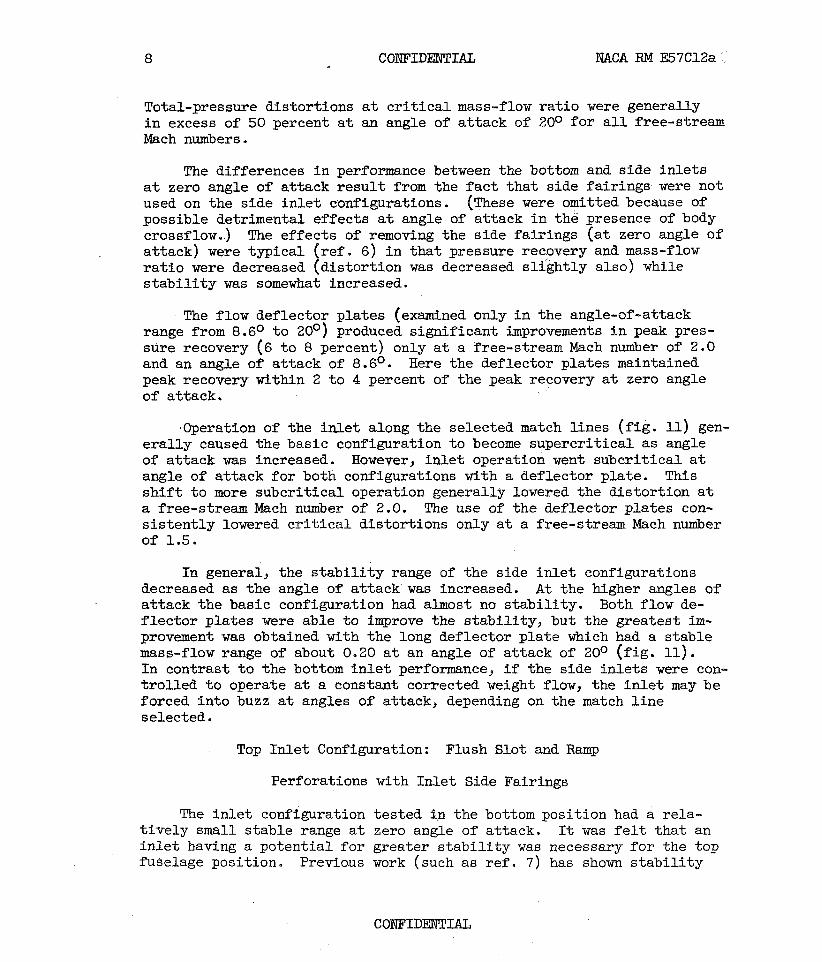
Total-pressure distortions at critical mass-flow ratio were generally in excess of 50 percent at an angle of attack of 20° for all free-stream Mach ntmbers.
The differences in performance between the bottom and side inlets at zero angle of attack result from the fact that side fairings were not used on the side inlet configurations. (~hese were omitted because of possible detrimental effects at angle of attack in the presence of body crossflow.) The effects of removing the side fairings (at zero angle of attack) were typical (ref. 6) in that pressure recovery and mass-flow ratio were decreased (distortion was decreased slightly also) while stability was somewhat increased.
The flow deflector plates (examined only in the angle-sf-attack range from 8.6O to 20°) produced significant improvements in peak pres- sure recovery (6 to 8 percent) only at a free-stream Mach number of 2.0 and an angle of attack of 8.6O. Here the deflector plates maintained peak recovery within 2 to 4 percent of the peak recovery at zero angle of attack.
-Operation of the inlet along the selected match lines (fig. 11) gen- erally caused the basic configuration to become supercritical as angle of attack was increased. However, inlet operation went subcritical at angle of attack for both configurations with a deflector plate, This shift to more subcritical operation generally Lowered the distortion at a free-stream Mach number of 2.0. The use of the deflector plates con- sistently lowered critical. distortions only at a free-stream Mach number of 1.5.
In general, the stability range of the side inlet configurations decreased as the angle of attack was increased. At the higher angles of attack the basic configuration had almost no stability. Both flow de- flector plates were able to improve the stability, but the greatest im- provement was obtained with the long deflector plate which had a stable mass-flow range of about 0.20 at an angle of attack of 20° (fig. 11). In contrast to the bottom inlet performance, if the side inlets were con- trolled to operate at a eonstant corrected weight flow, the inlet may be forced into buzz at angles of attack, depending on the match line selected.
Top Inlet Configuration: Flush Slot and Ramp
Perforations with Inlet Side Fairings
The inlet configuration tested tn the bottom position had a rela- tively small stable range at zero angle of attack. It was felt that an inlet having a potential for greater stability was necessary for the top fuselage position. Previous work (such as ref. 7) has shown stability

NaCA RM E57C12a CONFIDENTIAL 9
improvement with the use of perforations on the compression surface ahead of the i n l e t . Accordingly, the top i n l e t configuration was modified t o include the perforated ramp as well as the f lush s l o t a t the throat . Vents were cut i n to the sides of the ramp ( f ig . 4(a)) t o provide addi- t i ona l bleed e x i t area which would be i n close proximity t o the perforations.
The performance of the combined ramp- and throat-bleed configura- t i on i s shown i n figure 12 a t zero angle of a t tack f o r varying amounts of bleed flow. The minimum bleed value A ~ / & of 0.130 represents
bleed through vents only (bleed doors closed); higher values indicate opening of the bleed doors toward the maximum position. Schlieren ob- servation showed that,over a large par t of the subcr i t ica l range, re- verse flow occurred through the forward rows of the perforations even a t the maximum bleed door opening. Despite th i s , peak pressure recovery and dis tor t ion levels were comparable to those obtained with throat bleed alone ( f i g . 8) , although c r i t i c a l recovery decreased somewhat. I n l e t s t a b i l i t y was approximately doubled t o a maximum value of about 20 per- cent of the c r i t i c a l mass flow.
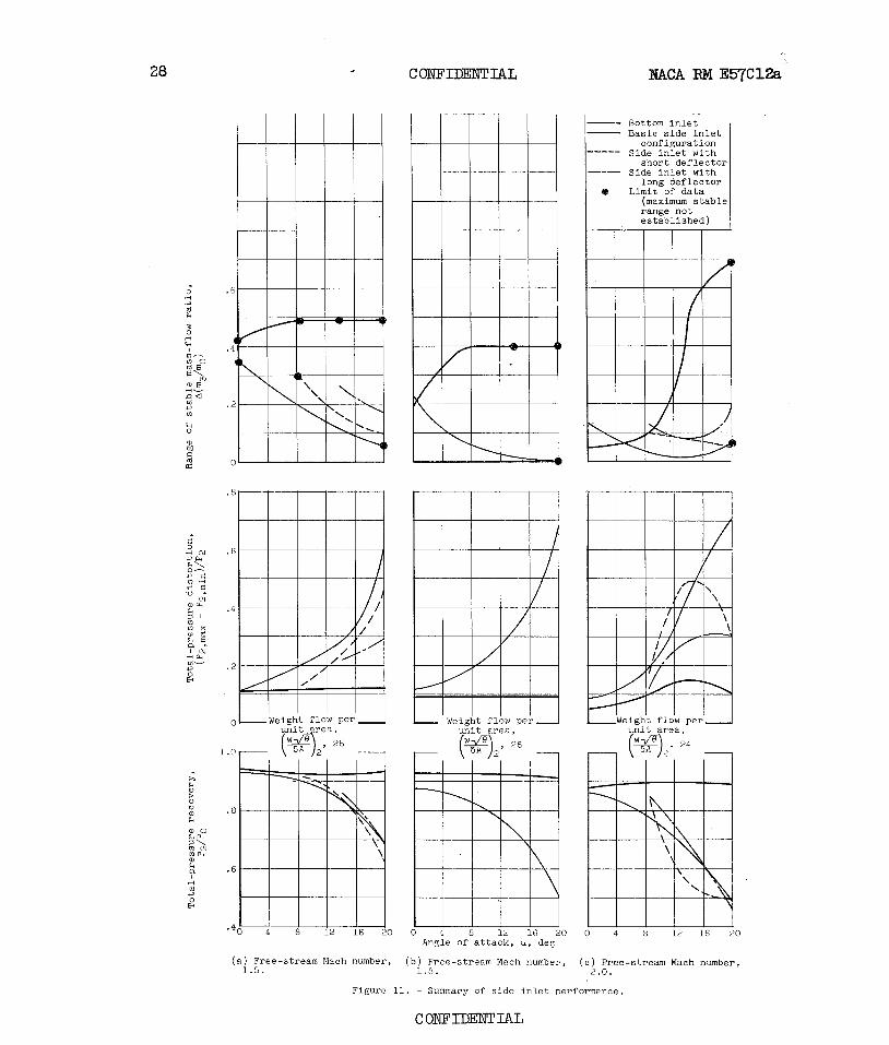
The jperformance of the top i n l e t configurations a t angle of a t tack i s shown i n f igure 13, and performance comparisons a r e made i n f igure 14 a t the same values of corrected weight flow selected f o r the s ide in l e t s . (1n some instances data were obtained only i n the range of angles of a t tack from 8.6' t o 20° .) For these configurations the bleed. flow ra- t i o s ~g/h include a value of 0.130 which represents bleed through the
vents alone. Data f o r the top i n l e t configurations (basic configuration or f l a t approach t o the in l e t , rounded approach, and f l a t approach with canopy) were obtained a t an A ~ / A . . ~ of 0.285. Limited data a t an
A ~ / A ~ of 0.595 with the f l a t approach t o the i n l e t ( f ig . 13(b) ) showed
no improvement i n performance with t h i s increased bleed e x i t area.
As with the s ide i n l e t , large decreases i n pressure recovery re- sulted from increased angle of a t tack. A t a free-stream Mach number of 2.0 peak pressure recovery dropped from a value of 0.91 f o r the basic configuration a t zero angle of a t tack t o values of 0.50 t o 0.55 f o r a l l configurations a t an angle of a t tack of 20°. Distortions of the basic configuration were high a t the intermediate angles of a t tack (28 t o 37 percent) but dropped t o values near 15 percent a t an angle of a t tack of 20' ( f ig . 14) .
Significant gains i n pressure recovery a t a l l Mach numbers and an- gles of a t tack were obtained by the substi tution of' a rounded f o r a f l a t approach t o the i n l e t ( f ig . 14) a Distortions were reduced but remained r e l a t ive ly high, generally over 20 percent a t the intermediate angles of a t tack. These performance improvements were i n par t dse t o be t te r
COW IDENTIAL

10 CONFIDENTIAL NACA RM E57C12e
streamlining in the direction of crossflow and in part to the greater boundary-layer removal capabilities of the rounded approach which had an h/t as small as 1 only in the vertical center plane.
The use of a canopy in front of the inlet with the flat approach adversely affected pressure recovery and distortion at low angles of attack (less than 4O). However, at higher angles of attack pressure re- covery was improved somewhat and very large gains were made in reducing distortion; for example, at a free-stream Mach number of 2.0 and an an- gle of attack of 14O, distortion decreased from 37 to 7 percent (fig. 14) .
Figure 13 illustrates that the top inlet configurations, when op- erated at a constant corrected weight flow, are forced into a more sub- critical operation by angle of attack without generally being forced into buzz as were the side inlets. The stability of the top inlet con- figurations was generally maintained with angle of attack at a mass-flow ratio range of 0.20 to 0.40. In some instances, however, the stability decreased to a mass-flow ratio range of 0.10 or less at the intermediate angles of attack.
SUMMARY OF RESULTS
An experimental investigation to determine the total-pressure re- covery, distortion, and stability up to an angle of attack of 20° of a 14' ramp-type inlet with throat bleed and located in three circumferen- tial fuselage positions was conducted in the Lewis 8- by 6-foot super- sonic wind tunnel at free-stream Mach numbers of 1.5, 1.8, and 2.0. The following results were obtained:
1. The angle-of-attack performance of the bottom inlet was superior to that of the side and top inlet configurations. Up to an angle of at- tack of 20°, peak total-pressure recovery of the bottom inlet varied less than 2 percent, distortions were below 15 percent, and the stable mass-flow ratio range increased to values as large as 0.69. This angle- of-attack performance was maintained with the fuselage diverter height reduced to one-third the boundary-layer thickness at zero angle of attack.
2. Angle of attack reduced peak pressure recoveries of all side in- let configurations to values near 0.50 at an angle of attack of 20° and a free-stream Mach number of 2.0 and inc~eased critical distortions to values in excess of 50 percent. The configurations with a flow deflector plate produced significant improvements in peak pressure recovery (6 to 8 percent) only at a free-stream Mach number of 2.0 and an angle of attack of 8.6'.

NACA RM E57C12a CONFlDENTLaL 11
3. The pressure recoveries of the top inlet configurations were also reduced with angle of attack to values near 0.50 at an angle of attack of 20° and a free-stream Mach number of 2.0. The distortion of the top inlet with flat approach was high (28 to 37 percent) at the in- termediate angles of attack but at an angle of attack of 20° dropped to about 15 percent or less. The substitution of a rounded for a flat ap- proach to the inlet improved pressure recovery and distort%ons, but dis- tortions were still relatively high, generally in excess of 20 percent.
4. Placing a canopy in front of the top inlet with the flat ap- proach decreased pressure recovery and increased distortions at low an- gles of attack. However, at higher angles of attack the canopy improved the pressure recovery somewhat and greatly reduced distortions.
5. At selected engine match conditions (constant corrected weight flow close to optimum thrust-minus-drag at zero angle of attack) the top and bottom inlet configurations were forced subcritical and the side in- let was forced supercritical with angle of attack. With the use of flow deflector plates side inlet operation at these same weight flows was sub- critical over the entire range of angle of attack.
Lewis Flight Propulsion Laboratory National Advisory Committee for Aeronautics
Cleveland, Ohio, March 19, 1957
1. Kremzier, Ehil J., and Campbell, Robert C.: Angle-of-Attack Super- sonic Performance of a Configuration Consisting of a Ramp-Type Scoop Inlet Located Either on Top or Bottom of a Body of Revolution. NACA RM E54C09, 1954.
2. Valerino, Alfred S., Pennington, Donald B., and Vargo, Donald J.: Effect of Circumferential Location on Angle of Attack Performance of Twin Half-Conical Scoop-Type Inlets Mounted Symmetrically on the RM-10 Body of Revolution. NACA RM E53G09, 1953.
3. Easel, Iowell E., Lankford, John L., and Robins, A. W.: Investiga- tion of a Half-Conical Scoop Inlet Mounted at Five Alternate Cir- cumferential Locations Around a Circular Fuselage. Pressure- Recovery Results at a Mach Number of 2.01. NACA RM Z53D30b, 1953.
4. Hasel, Lowell E.: The Performance of Conical Supersonic Scoop Inlets on Circular Fuselages. NACA RM L53114a, 1953.
CONFIDENTIAL

NACA RM E57C12a
5. Campbell, Robert C.: Performance of Supersonic Ramp-Type Side Inlet with Combinations of Fuselage and Inlet Throat Boundary-Layer Removal. NACA RM E56Al.7, 1956.
6. Mitchell, Glenn A., and Campbell, Robert C.: Performance of a Supersonic Ramp-Srpe Side Inlet with Ram-Scoop Throat Bleed and Varying Fuselage Boundary-Layer Removal Mach Number Range 1.5 to 2.0. NACA RME56126, 1957.
7. Allen, John L.: Performance of a Blunt-Lip Side Inlet with Ramp Bleed, By-pass, and a Long Constant-Area Duct Ahead of the Engine: Mach Numbers 0.66 and 1.5 to 2.1. NACA RM E56J01, 1956.

CO
NFID
EN
TIA
L


(e) Basic configuration. (No def l e c t ~ r plate . )
(b) Side i n l e t with short flow deflector p la te . ( c ) Side i n l e t with long flow deflector p la te ,
Figure 3. - Side i n l e t conf iguratiozls. Flush s l o t bleed, 14' ramp without s ide fair ings.
CONFIDENTIAL I

16 C
ON
FIDE
NT
IAL
XACA Rlvl E57C
L2dt

(b) With rounded approach.
(c) With canopy.
Figure 4. - Concluded. Top i n l e t cowigurations. Flush s lo t bleed and ramp perforations,
14O ramp in l e t with side fa i r ings .
P ~ 1 \ ' T ~ ~ T b . T.

NA
CA RM
E57C12a

Y - (a) Survey rake on top of body, rounded approach.
.2 . 4 .6 .8 1.0 0 .2 .4 .6 .8 1.0 0 .2 .4 Measured total-pressure ratio, pl/pO
(b) Survey rake on bbttom of body, flat approach.
Figure 6. - Radial total-pressure profiles ahead of inlet on inlet center plane.

3 I FLee-stream' Mach' number, Mo, 1.5
I I I
( o ) Survey rake on side of body, flat approac
(8) Suvvey rake
Figure 6. - Concluded.
.2 .4 .6 .8 1.0 Measured total-pressure ratio, pl/PO
on side of body, flat approach with long flow deflector plate.
Radial total-pressure profiles ahead of inlet on inlet center plane.

NACA RM E57C12a
CO
NFID
EN
TIA
L

Ratio of bleed minimum exit area to inlet
throat area,
W A t
I Free-stream Mach number, M,, 1.8 I
Mass-flow ratio, m3/m0
Figure 8. - Effect of inlet throat bleed on performance of bottom inlet. Angle of attack, OO; fuselage diverter height parameter, 1.

.4 Free-stream Mach number, Mo, 1.5
.4 .5 .6 .7 .8 .9 Mass-flow r a t i o , m3/mo
Tailed symbols denote data taken i n i n l e t
( a ) Fuselage d iver ter height parameter, 1.
Figure 9. - Angle-of-attack performance f o r bottom i n l e t . Ratio of bleed minimum e x l t area t o i n l e t throat area, 0.155.

Tailed symbols denote data taken i n i n l e t pulsing regions; numbers denote t o t a l amplitude of pulses,
.4 .5 .6 .7 .8 .9 Mass-flow r a t i o , m3/mo
( b ) Fuselage d iver ter height parameter, 1/3.
Figure 9 . - Concluded. Angle-of-attack performance fo r bottom i n l e t . Ratio a f bleed minimum e x i t area t o i n l e t throat a rea , 0.155.

WACA
BM E57C12a
C ON
FIDEN
T IAL
zd
/(uie
'zd
-
xe
m8
zd)
'uo
y?
.~o
?s
yp
am
ss
a~
d-~
e?
oL
O
d/Zd 'L
lian
oo
a.~
a.rn
ss
a~
d-p
?o
&
C ON
FIDE
NT
IAL

Tailed symbols denote data taken i n i n l e t pulsing regions; numbers denote t o t a l
(b) Side in l e t with short deflector plate.
Figure 10. - Continued. Angle-of-attack performance fo r side in l e t configurations. Ratio of bleed minimum exi t area t o i n l e t throat area, 0.155; fuselage diverter height parameter, 1.

c om IDENT IAL ~ C A RM E57C12a
- - - Bottom inlet 1- Basic side inlet
----- configuration Side inlet with
short deflector Side inlet with
long deflector O Limit of data
(maximum stable range not established)
(a) Free-stream Mach number, (b) Free-stream Mach number, (c) Free-stream Mach number, 1.5. 1.0. 2.0.
Figure 11. - Summary of side inlet performance.
C ONFIDEMl IAL

NACA RM E57C12a
Ratio of bleed minimum e x i t a r ea t o i n l e t t h roa t area,
ABIA~
Tailed symbols d e n ~ t e da t a taken i n i n l e t puls ing regions; numbers denote t o t a l amplitude of pulses , percent d i f fuse r t o t a l Dressure
.6 .7 .8 .9 1.0 Mass-flow r a t i o , m3/mo
Figure 12. - Ef fec t of i n l e t t h roa t bleed on per- formance of t op i n l e t . Free-stream Mach number, 2.0; angle of a t tack , OO; fuselage d ive r t e r height parameter, 1.

Mass-flow ratio, m3/mo
Tailed symbols denote data taken in inlet pulsing regions; numbers denote total
(a) Basic top inlet configuration, flat approach. Ratio of bleed minimum exit area to inlet throat area, 0.285.
Figure 13. - Angle-of-attack performance for top inlet configurations. Fuselage diverter height parameter, 1.

Angle of attack, a, deg I
Tailed symbols denote data taken in inlet
(b) Top inlet, flat approach. Ratio of bleed minimum exit area to inlet throat area, 0.595.
Figure 13. - Continued. Angle-of-attack performance for top inlet configurations. Fuselage diverter height parameter, 1.
.3 .4 .5 .6 . 7 .8 Mass-flow ratio, m d m o
Angle of attack, a,
1 1 1 1 deg 8.6 14
Tailed symbols denote data taken in inlet pulsing regions; numbers denote total amplitude of pulses, percent diffuser
(c) Top inlet with rounded approach. Ratio of bleed minimum exit area to inlet throat area, 0.285. M u'i
2 Figure 13. - Continued. Angle-of-attack performance for top inlet configurations. Fuselage diverter height parameter, 1. p
%'

Tailed symbols denote data taken in inlet pulsing regions; numbers denote total amplitude of pulses, percent diffuser total pressure
(d) Top inlet with canopy, flat approach. Ratio of bleed minimum exit area to inlet throat area, 0.285.
Figure 13. - Concluded. Angle-of-attack performance for top inlet configurations. Fuselage diverter height parameter, 1.

ColQ'IDENTIAL NACA RM E57C12a
ol .4 a 1
a C fi - 4
2 g 5 m r l cv a - a fi $4 .2 ?B ' r l m x @ r l m -a E,
E4 2 -
(a) Free-stream Mach number, 1.5.
Figure 14
Basic ~ o p Inlet configuration
Top inlet with rounded approach
Top inlet with
0 4 8 12 16 20 0 4 8 12 16 20 Angle of attack, a, deg
b) Free-stream Mach number, (c) Free-stream Mach number, 1.8. 2 - 0 .
- Summary of top inlet performance.
CONFIDENTIAL
N.4CA - Langley Field, Va.