Embed Size (px)
Citation preview

New Insights in Synthetic Fiber Rope Elongation and its Detection forUltra Lightweight Tendon Driven Series Elastic Robots
Jérôme Kirchhoff and Oskar von Stryk
Abstract— Selecting transmission components for tendondriven actuation systems can be challenging because of thevariety of available solutions. Synthetic fiber ropes have greatpotential for these systems, but the typically provided character-istics are not always suitable to decide whether a rope should beused in the specific system or not. In this paper, a comparativeevaluation of the elongation characteristic regarding differentrope materials, manufacturers and temperatures is presented.Further, the influence of guiding pulleys is investigated con-cerning the application at ultra lightweight tendon drivenseries elastic robots. The knowledge gained from the performednew rope analysis supports the design process of tendondriven robots. Since tendon elongation influences the controlperformance and joint torque estimation of the regarded class ofrobots, a novel observer-based approach for tendon elongationdetection is presented and evaluated, which enables to monitorwear for quality assurance and to avoid failures.
I. INTRODUCTION
One of the current trends in industrial automation isbringing humans and robots together to perform a task in thesame workspace without fences. This can gain productivity,since the automation process can benefit from the human’sdexterity and process knowledge, as well as from the robot’srepetitive performance without tiredness.
Safe physical human-robot interaction (pHRI) is crucialin this scenario. The kinetic energy that can be transferredduring a collision without severe injuries is bounded by thehuman’s biomechanical limits [1]. To stay within these limits,even small joint elasticities can be introduced in the joint todecouple the motor and link inertia, causing a maximumtransient collision force determined only by the link inertia,and further, reducing the robot’s effective mass.
A typical approach to develop a robot that is capable forpHRI is to downscale industrial robot arms with motors stillplaced in the joints. This reduces the robot’s effective massbut is limited by reach and payload. Introducing tendons inthe robot’s mechanical design enables to shift the motorsaway from the joints towards the base, which results in adifferent class of lightweight robots.
Besides industrial automation, tendons can also be relevantfor other fields of human near applications. Reproducinghuman or animal like walking can benefit from the use oftendons. Even if their use is only passive without actuation,it is possible to realize a joint coupling more similar to thebiomechanical mechanisms which helps to synchronize thejoints and facilitates the control task [2]. Also for wearable
The authors are with the Simulation, Optimization and Robotics Group,Department of Computer Science, Technische Universität Darmstadt, Ger-many [kirchhoff,stryk]@sim.tu-darmstadt.de
robots, e.g., to support elderly people performing a motionor new types of orthoses, tendons can help to create a morecomfortable and lightweight structure.
Independent of the specific application, tendons can beimplemented in different ways. For instance belts or steelcables can be used to move joints, as done in some industrialrobots. But these solutions are not necessarily suitable forstructures where pulleys with small radii are used and highforces have to be transmitted. In these cases, synthetic ropesshould be considered. In the last decade the evolution insynthetic fiber materials and production processes led toproducts with impressing strength (see Table I).
Since the scale of robots in the vicinity of humans islimited by safety and weight, also the used pulleys andthus rope diameter is limited. Synthetic ropes with smalldiameters are typically used in the area of sailing and sportactivities that use kites or parachutes. Here, the relevantparameters are the rope’s diameter, breaking strength andweight. But these are not always suitable to decide aboutthe utilization potential in a complex mechatronical systemwhere a rope is wound around multiple pulleys. Especially,the irretrievable rope elongation characteristic (creep) isa relevant factor that should be known and continuouslymonitored because of the negative influence on the jointposition control performance.
The contribution of this work consists of• new comparative creep experiments regarding different
fiber materials, manufacturers, and diameters,• the experimental evaluation of the influence of a differ-
ent amount of pulleys on commonly used HMPA fiber,• and an observer-based approach for tendon elongation
detection to monitor wear for quality assurance.The performed experiments gives new insights into the ropeelongation characteristics, that are typically not provided bythe rope manufacturers.
II. RELATED WORK AND BACKGROUND
Using ropes as tendons in robotic systems provides theopportunity of small scale mechanical design, because of thehigh flexibility, high strength to weight ratio, and possiblesmall bending radius. That is the reason why they are usedfor example in systems like anthropomorphic hands [3]–[5],bipedal robots [6], [7], small size ultra lightweight robot arms[8]–[10] or novel actuation approaches [11].
Synthetic ropes can be braided in different ways usingdifferent fibers. These fiber materials have evolved in the lastdecades improving the strength to weight ratio and reducingcreep effects. A comparison of rope constructions and fiber
This is the author's version of an article that has been published in the Proceedings of the IEEE International Conference on Advanced Intelligent Mechatronics (AIM), Munich, July 3-7, 2017, pp. 64-69. The final version of record is available at https://doi.org/10.1109/AIM.2017.8013996
Copyright (c) 2017 IEEE. Personal use of this material is permitted. Permission from IEEE must be obtained for all other uses, in any current or future media, including reprinting/republishing this material for advertising or promotional purposes, creating new collective works, for resale or redistribution to servers or lists, or reuse of any copyrighted component of this work in other works.
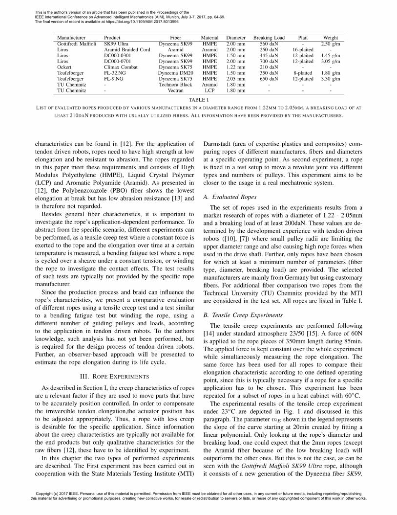
Manufacturer Product Fiber Material Diameter Breaking Load Plait WeightGottifredi Maffioli SK99 Ultra Dyneema SK99 HMPE 2.00 mm 560 daN - 2.50 g/mLiros Aramid Braided Cord Aramid Aramid 2.00 mm 250 daN 16-plaited -Liros DC000-0301 Dyneema SK99 HMPE 1.50 mm 445 daN 12-plaited 1.45 g/mLiros DC000-0701 Dyneema SK99 HMPE 2.00 mm 700 daN 12-plaited 3.05 g/mOckert Climax Combat Dyneema SK75 HMPE 1.22 mm 210 daN - -Teufelberger FL-32.NG Dyneema DM20 HMPE 1.50 mm 350 daN 8-plaited 1.80 g/mTeufelberger FL-9.NG Dyneema SK75 HMPE 2.05 mm 650 daN 12-plaited 3.30 g/mTU Chemnitz - Technora Black Aramid 1.80 mm - - -TU Chemnitz - Vectran LCP 1.80 mm - - -
TABLE ILIST OF EVALUATED ROPES PRODUCED BY VARIOUS MANUFACTURERS IN A DIAMETER RANGE FROM 1.22MM TO 2.05MM, A BREAKING LOAD OF AT
LEAST 210DAN PRODUCED WITH USUALLY UTILIZED FIBERS. ALL INFORMATION HAVE BEEN PROVIDED BY THE MANUFACTURERS.
characteristics can be found in [12]. For the application oftendon driven robots, ropes need to have high strength at lowelongation and be resistant to abrasion. The ropes regardedin this paper meet these requirements and consists of HighModulus Polyethylene (HMPE), Liquid Crystal Polymer(LCP) and Aromatic Polyamide (Aramid). As presented in[12], the Polybenzoxazole (PBO) fiber shows the lowestelongation at break but has low abrasion resistance [13] andis therefore not regarded.
Besides general fiber characteristics, it is important toinvestigate the rope’s application-dependent performance. Toabstract from the specific scenario, different experiments canbe performed, as a tensile creep test where a constant force isexerted to the rope and the elongation over time at a certaintemperature is measured, a bending fatigue test where a ropeis cycled over a sheave under a constant tension, or windingthe rope to investigate the contact effects. The test resultsof such tests are typically not provided by the specific ropemanufacturer.
Since the production process and braid can influence therope’s characteristics, we present a comparative evaluationof different ropes using a tensile creep test and a test similarto a bending fatigue test but winding the rope, using adifferent number of guiding pulleys and loads, accordingto the application in tendon driven robots. To the authorsknowledge, such analysis has not yet been performed, butis required for the design process of tendon driven robots.Further, an observer-based approach will be presented toestimate the rope elongation during its life cycle.
III. ROPE EXPERIMENTS
As described in Section I, the creep characteristics of ropesare a relevant factor if they are used to move parts that haveto be accurately position controlled. In order to compensatethe irreversible tendon elongation,the actuator position hasto be adjusted appropriately. Thus, a rope with less creepis desirable for the specific application. Since informationabout the creep characteristics are typically not available forthe end products but only qualitative characteristics for theraw fibers [12], these have to be identified by experiment.
In this chapter the two types of performed experimentsare described. The First experiment has been carried out incooperation with the State Materials Testing Institute (MTI)
Darmstadt (area of expertise plastics and composites) com-paring ropes of different manufactures, fibers and diametersat a specific operating point. As second experiment, a ropeis fixed in a test setup to move a revolute joint via differenttypes and numbers of pulleys. This experiment aims to becloser to the usage in a real mechatronic system.
A. Evaluated Ropes
The set of ropes used in the experiments results from amarket research of ropes with a diameter of 1.22 - 2.05mmand a breaking load of at least 200daN. These values are de-termined by the development experience with tendon drivenrobots ([10], [7]) where small pulley radii are limiting theupper diameter range and also causing high rope forces whenused in the drive shaft. Further, only ropes have been chosenfor which at least a minimum number of parameters (fibertype, diameter, breaking load) are provided. The selectedmanufacturers are mainly from Germany but using customaryfibers. For additional fiber comparison two ropes from theTechnical University (TU) Chemnitz provided by the MTIare considered in the test set. All ropes are listed in Table I.
B. Tensile Creep Experiments
The tensile creep experiments are performed following[14] under standard atmosphere 23/50 [15]. A force of 60Nis applied to the rope pieces of 350mm length during 85min.The applied force is kept constant over the whole experimentwhile simultaneously measuring the rope elongation. Thesame force has been used for all ropes to compare theirelongation characteristic according to one defined operatingpoint, since this is typically necessary if a rope for a specificapplication has to be chosen. This experiment has beenrepeated for a subset of ropes in a heat cabinet with 60◦C.
The experimental results of the tensile creep experimentunder 23◦C are depicted in Fig. 1 and discussed in thisparagraph. The parameter mE shown in the legend representsthe slope of the curve starting at 20min created by fitting alinear polynomial. Only looking at the rope’s diameter andbreaking load, one could expect that the 2mm ropes (exceptthe Aramid fiber because of the low breaking load) willoutperform the other ones. But this is not the case, as can beseen with the Gottifredi Maffioli SK99 Ultra rope, althoughit consists of a new generation of the Dyneema fiber SK99.
This is the author's version of an article that has been published in the Proceedings of the IEEE International Conference on Advanced Intelligent Mechatronics (AIM), Munich, July 3-7, 2017, pp. 64-69. The final version of record is available at https://doi.org/10.1109/AIM.2017.8013996
Copyright (c) 2017 IEEE. Personal use of this material is permitted. Permission from IEEE must be obtained for all other uses, in any current or future media, including reprinting/republishing this material for advertising or promotional purposes, creating new collective works, for resale or redistribution to servers or lists, or reuse of any copyrighted component of this work in other works.
0 10 20 30 40 50 60 70 800
0.2
0.4
0.6
0.8
1
1.2
1.4
1.6
Tensile Creep Experiments 23◦C
t [min]
Elongation[%
]
G. Maffioli SK99 2.00mm (mE : 1.5)Liros Aramid 2.00mm (mE : 0.53)Liros SK99 1.50mm (mE : 0.6)Liros SK99 2.00mm (mE : 0.72)Ockert SK75 1.50mm (mE : 0.56)
Teufelberger DM20 1.50mm (mE : 0.8)Teufelberger SK75 2.05mm (mE : 0.52)TUC Technora Black 1.80mm (mE : 0.071)TUC Vectran 1.80mm (mE : 0.29)
Fig. 1. Elongation results of the tensile creep experiments exerting aconstant force of 60N to the ropes with 350mm length at 23◦C
Comparing the Aramid fiber rope with the Ockert ClimaxCombat that has a rather similar breaking load, shows afinal elongation that is more than half as large as smallerdiameters. The elongation slopes of these ropes are almostthe same. The final elongation of the set of ropes with adiameter smaller that 2mm is within a range of almost 0.2%.Besides this, the two fibers Technora Black and Vectranprovided by (MTI) show less elongation slope than the otherropes.
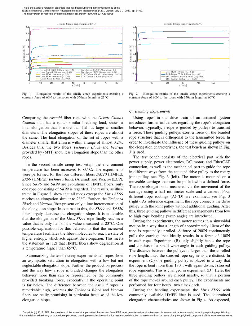
In the second tensile creep test setup, the environmenttemperature has been increased to 60◦C. The experimentswere performed for the four different fibers DM20 (HMPE),SK99 (HMPE), Technora Black (Aramid) and Vectran (LCP).Since SK75 and SK99 are evolutions of HMPE fibers, onlyone rope consisting of SK99 is regarded. The results, as illus-trated in Figure 2, show that all ropes except the Liros SK99reaches an elongation similar to 23◦C. Further, the TechnoraBlack and Vectran fiber present only a low incrementation ofthe elongation slope. In contrast to this, the SK99 and DM20fiber largely decrease the elongation slope. It is noticeablethat the elongation of the Liros SK99 rope finally reaches avalue that is only half of the value measured at 23◦C. Onepossible explanation for this behavior is that the increasedtemperature facilitates the fiber molecules to reach a state ofhigher entropy, which acts against the elongation. This meetsthe statement in [12] that HMPE fibers show degradation ata temperature higher than 65◦C.
Summarizing the tensile creep experiments, all ropes showan asymptotic saturation in elongation with a low but notneglectable elongation slope. Further, the production processand the way how a rope is braided changes the elongationbehavior more than can be represented by the commonlyprovided breaking force, especially if the operating pointis far below. The difference between the Aramid ropes isremarkable high, whereas the Technora Black and Vectranfibers are really promising in particular because of the lowelongation slope.
0 10 20 30 40 500
0.1
0.2
0.3
0.4
0.5
0.6
0.7
0.8
Tensile Creep Experiments 60◦C
t [min]
Elongation[%
]
Liros SK99 1.50mm (mE : 0.2)Teufelberger DM20 1.50mm (mE : 0.3)TUC Technora Black 1.80mm (mE : 0.19)TUC Vectran 1.80mm (mE : 0.28)
Fig. 2. Elongation results of the tensile creep experiments exerting aconstant force of 60N to the ropes with 350mm length at 60◦C
C. Bending Experiments
Using ropes in the drive train of an actuated systemintroduces further influences regarding the rope’s elongationbehavior. Typically, a rope is guided by pulleys to transmita force. These guiding pulleys exert a force on the braidedrope structure that is orthogonal to the transmitted force. Inorder to investigate the influence of these guiding pulleys onthe elongation characteristics, the test bench as shown in Fig.3 is used.
The test bench consists of the electrical part with thepower supply, power electronics, DC motor, and EtherCATconnection, as well as the mechanical part to guide the ropein different ways from the actuated drive pulley to the rotaryjoint pulley, see Fig. 3 (left). The motor is mounted on amoveable carriage that can be pulled with a defined force.The rope elongation is measured via the movement of thecarriage using a half millimeter scale and a camera. Fourdifferent rope routings (A)-(D) are examined, see Fig. 3(right). As reference experiment, the rope connects the drivepulley with the joint pulley without additional guiding. Afterthis, three guiding pulleys in different arrangements from lowto high rope bending (wrap angle) are introduced.
During the experiments, the motor rotates in a sinusoidalmotion in a way that a length of approximately 10cm of therope is repeatedly unrolled. A force of 200N continuouslypulls the carriage that ideally results in a force of 100Nin each rope. Experiment (B) only slightly bends the ropeand consists of a small wrap angle in each guiding pulley.The distance between the pulleys is larger than the unrolledrope length, thus, the stressed rope segments are distinct. Inexperiment (C) one guiding pulley is placed in a way thatthe rope is bent more than 180◦, with again distinct stressedrope segments. This is changed in experiment (D). Here, thethree guiding pulleys are placed nearby, so that a portionof the rope moves around each pulley. The experiments areperformed for four hours, two times each.
During the bending experiments the Liros SK99 withcommonly available HMPE fiber is used. The determinedelongation characteristics are shown in Fig 4. As expected,
This is the author's version of an article that has been published in the Proceedings of the IEEE International Conference on Advanced Intelligent Mechatronics (AIM), Munich, July 3-7, 2017, pp. 64-69. The final version of record is available at https://doi.org/10.1109/AIM.2017.8013996
Copyright (c) 2017 IEEE. Personal use of this material is permitted. Permission from IEEE must be obtained for all other uses, in any current or future media, including reprinting/republishing this material for advertising or promotional purposes, creating new collective works, for resale or redistribution to servers or lists, or reuse of any copyrighted component of this work in other works.
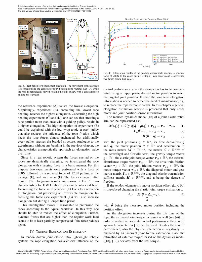
Fig. 3. Test bench for bending test execution. The movement of the carriageis recorded using the camera for four different rope routings (A)-(D), whilethe rope is periodically moved rotating the joint pulley, with a constant forcepulling the carriage.
the reference experiment (A) causes the lowest elongation.Surprisingly, experiment (B), containing the lowest ropebending, reaches the highest elongation. Concerning the highbending experiments (C) and (D), one can see that stressing arope portion more than once with a guiding pulley, results ina higher elongation. The high elongation of experiment (B)could be explained with the low wrap angle at each pulleythat also reduces the influence of the rope friction whichkeeps the rope forces almost unchanged, but additionallyevery pulley stresses the braided structure. Analogue to theexperiments without any bending in the previous chapter, thecharacteristics asymptotically approach an elongation valueover time.
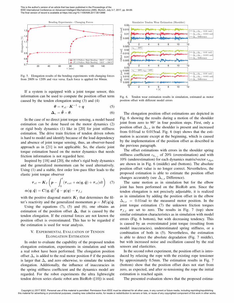
Since in a real robotic system the forces exerted on theropes are dynamically changing, we investigated the ropeelongation with changing force in a basic manner. For thispurpose two experiments were performed with a force of200N followed by a reduced force of 120N pulling at thecarriage (E), and vice versa (F). The forces changed after80min. The elongation results are shown in Fig. 5. Twocharacteristics for HMPE fiber ropes can be observed here.Decreasing the force in experiment (E) leads to a reductionin elongation, but preserving an irreversible elongation. In-creasing the force (see experiment (F)) will also increaseelongation but during a longer time period.
This investigation makes it reasonable to pretension theropes according to the typical workload. In this way, oneshould be able to reduce the effect of elongation. Further,dynamic forces that are higher than the regular work loadseems to be at least partially compensated if the force reducesagain.
IV. TENDON ELONGATION ESTIMATION
In tendon driven joint elastic ultra lightweight roboticsystems the rope elongation has a crucial influence on the
50 100 150 2000.9
1
1.1
1.2
1.3
1.4
1.5
1.6
Bending Experiments - Constant Force 200N
t [min]
Elongation[%
]
(A) Reference(B) 3 Pulleys, Low Bending(C) 3 Pulleys, High Bending(D) 3 Pulleys, High Bending, Near
Fig. 4. Elongation results of the bending experiments exerting a constantforce of 200N to the ropes during 240min. Each experiment is performedtwo times (same line color).
control performance, since the elongation has to be compen-sated using an appropriate desired motor position to reachthe targeted joint position. Further, the long term elongationinformation is needed to detect the need of maintenance, e.g.to replace the rope before it breaks. In this chapter a generalelongation estimation scheme is presented that only needsmotor and joint position sensor information.
The reduced dynamics model [16] of a joint elastic robotarm can be represented as:
M(q)q̈ +C(q, q̇)q̇ + g(q) + τ f,j = τ el + τ ext (1)
Imθ̈ + τ f + τ el = τm (2)K(θ − q) = τ el (3)
with the joint positions q ∈ Rn, its time derivatives q̇and q̈, the motor position θ ∈ Rn and acceleration θ̈,the mass matrix M ∈ Rn×n, the matrix C ∈ Rn×n ofthe centrifugal and Coriolis term, the gravity torque vectorg ∈ Rn, the elastic joint torque vector τ el ∈ Rn, the externaldisturbance torque vector τ ext ∈ Rn, the drive train frictionvector τ f ∈ Rn, the joint friction vector τ f,j ∈ Rn, themotor torque vector τm ∈ Rn, the diagonal motor and gearinertia matrix Im ∈ Rn×n, the diagonal elastic transmissionstiffness matrix K ∈ Rn×n, and n being the degree offreedom.
If the tendon elongates, a motor position offset ∆e ∈ Rn
is introduced changing the elastic joint torque estimation toτ̂ el = K(θ + ∆e︸ ︷︷ ︸
θ̂
−q), (4)
with θ̂ being the measured motor position including theposition offset.
As the elongation increases during the life time of therope, the estimated joint torque increases as well (see (4)). Inorder to realize an accurate control performance the controlapproach presented in [17] can be used. Besides the controlperformance, also the physical interaction is negatively in-fluenced by an incorrect joint torque estimation, since theestimation of external torques based on the dynamics model([18], [19]) deviates from the real torque.
This is the author's version of an article that has been published in the Proceedings of the IEEE International Conference on Advanced Intelligent Mechatronics (AIM), Munich, July 3-7, 2017, pp. 64-69. The final version of record is available at https://doi.org/10.1109/AIM.2017.8013996
Copyright (c) 2017 IEEE. Personal use of this material is permitted. Permission from IEEE must be obtained for all other uses, in any current or future media, including reprinting/republishing this material for advertising or promotional purposes, creating new collective works, for resale or redistribution to servers or lists, or reuse of any copyrighted component of this work in other works.
20 40 60 80 100 120 1400.7
0.8
0.9
1
1.1
1.2
1.3
Bending Experiments - Changing Forces
t [min]
Elongation[%
]
(E) 3 Pulleys, High Bending - 200N → 120N(F) 3 Pulleys, High Bending - 120N → 200N
Fig. 5. Elongation results of the bending experiments with changing forcesfrom 200N to 120N and vice versa. Each force is applied for 80min.
If a system is equipped with a joint torque sensor, thisinformation can be used to compute the position offset termcaused by the tendon elongation using (3) and (4)
θ = τ el ·K−1 + q (5)
∆e = θ̂ − θ. (6)
In the case of no direct joint torque sensing, a model basedestimation can be done based on the motor dynamics (2)or rigid body dynamics (1) like in [20] for joint stiffnessestimation. The drive train friction of tendon driven robotsis hard to model and identify because of the load dependencyand absence of joint torque sensing, thus, an observer-basedapproach as in [21] is not applicable. So, the elastic jointtorque estimation based on the motor dynamics that needsfriction information is not regarded here.
Inspired by [18] and [20], the robot’s rigid body dynamicsand the generalized momentum can be used alternatively.Using (1) and a stable, first order low-pass filter leads to theelastic joint torque observer
τ el = KI
(p−
∫ t
0
(τ ext +α(q, q̇) + τ el)dt
)(7)
α(q, q̇) = C(q, q̇)T q̇ − g(q)− τ f,j
with the positive diagonal matrix KI that determines the fil-ter’s reactivity and the generalized momentum p = M(q)q̈.
Using the equations (7), (5) and (6), one obtains anestimation of the position offset ∆̂e that is caused by thetendon elongation. If the external forces are not known theposition offset is overestimated. This has to be regarded ifthe estimation is used for wear analysis.
V. EXPERIMENTAL EVALUATION OF TENDONELONGATION ESTIMATION
In order to evaluate the capability of the proposed tendonelongation estimation, experiments in simulation and witha real robot have been performed. The elongation positionoffset ∆e is added to the real motor position θ if the positionis larger that ∆e and zero otherwise, to simulate the tendonelongation. Additionally, the influence of inaccuracies inthe spring stiffness coefficient and the dynamics model areregarded. For the robot experiments the ultra lightweighttendon driven series elastic robot arm BioRob ([10]) is used.
0 2 4 6 8 10 120
0.005
0.01
0.015
0.02
Simulative Tendon Wear Estimation (Shoulder)
Offset[rad
]
∆̂e,s(∆e,s : 0.01 rad)
∆̂e,s(∆e,s : 0.015 rad)
∆̂e,s Difference
0 2 4 6 8 10 120
0.005
0.01
0.015
0.02
0.025
Offset[rad
] ǫke,s : 20%
∆̂e,s(∆e,s : 0.01 rad)
∆̂e,s(∆e,s : 0.015 rad)
∆̂e,s Difference
0 2 4 6 8 10 120
0.005
0.01
0.015
0.02
0.025
0.03
t [s]
Offset[rad
] ǫke,s : 20%, ǫdyn : 10%
∆̂e,s(∆e,s : 0.01 rad)
∆̂e,s(∆e,s : 0.015 rad)
∆̂e,s Difference
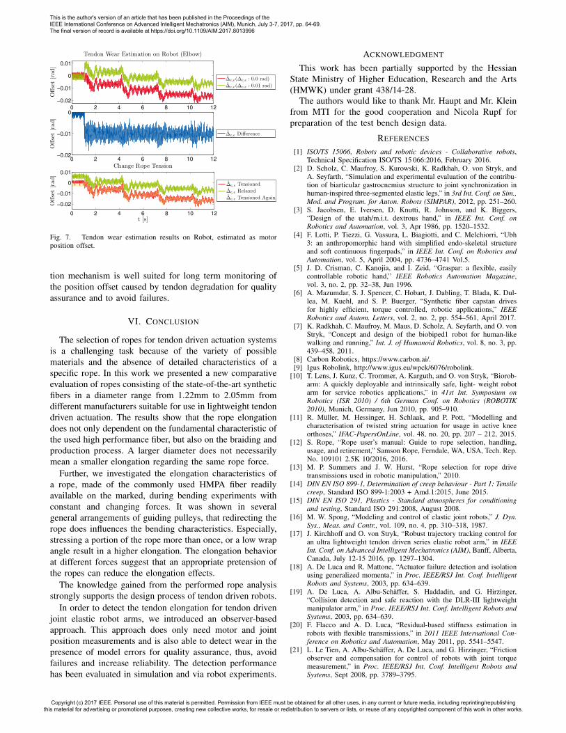
Fig. 6. Tendon wear estimation results in simulation, estimated as motorposition offset with different model errors
The elongation position offset estimations are depicted inFig. 6 showing the results during a motion of the shoulderjoint from zero to 90◦ in four position steps. First, only aposition offset ∆e,s in the shoulder is present and increasedfrom 0.01rad to 0.015rad. Fig. 6 (top) shows that the esti-mation is accurate except at the beginning, which is causedby the implementation of the position offset as described inthe previous paragraph.
The offset estimations with errors in the shoulder springstiffness coefficient εke,s
of 20% (overestimation) and with10% (underestimation) for each dynamics matrix/vector εdynare shown in in Fig. 6 (middle) and (bottom). The absoluteposition offset value is no longer correct. Nevertheless, theproposed estimation is able to estimate the position offsetchanges accurately (see ∆̂e,s Difference).
The same motion as in simulation but for the elbowjoint has been performed on the BioRob arm. Since thetendon elongation is not precisely adjustable, it is realizedas in simulation by adding the position offset in the elbow∆e,e = 0.01rad to the measured motor position. In thejoint torque estimation (7) the unknown friction torquesτ f,j are set to zero. The results in Fig. 7 (top) showsimilar estimation characteristics as in simulation with modelerrors (Fig. 6 bottom), but with decreasing tendency. Thisis caused by an overestimated joint torque (resulting frommodel inaccuracies), underestimated spring stiffness, or acombination of both in (5). Nevertheless, the estimationis able to detect the absolute degradation (Fig. 7 middle),but with increased noise and oscillation caused by the realsensors and elasticities.
In the second robot experiment, the position offset is intro-duced by relaxing the rope with the existing rope tensionerby approximately 0.5mm. The estimation results in Fig. 7(bottom) show that the position offset does not start fromzero, as expected, and after re-tensioning the rope the initialestimation is reached again.
The presented evaluation shows that the proposed estima-
This is the author's version of an article that has been published in the Proceedings of the IEEE International Conference on Advanced Intelligent Mechatronics (AIM), Munich, July 3-7, 2017, pp. 64-69. The final version of record is available at https://doi.org/10.1109/AIM.2017.8013996
Copyright (c) 2017 IEEE. Personal use of this material is permitted. Permission from IEEE must be obtained for all other uses, in any current or future media, including reprinting/republishing this material for advertising or promotional purposes, creating new collective works, for resale or redistribution to servers or lists, or reuse of any copyrighted component of this work in other works.
0 2 4 6 8 10 12
−0.02
−0.01
0
0.01
Tendon Wear Estimation on Robot (Elbow)Offset[rad]
∆̂e,e(∆e,e : 0.0 rad)
∆̂e,e(∆e,e : 0.01 rad)
0 2 4 6 8 10 12−0.02
−0.01
0
Offset[rad
]
∆̂e,e Difference
0 2 4 6 8 10 12
−0.02
−0.01
0
0.01
Change Rope Tension
t [s]
Offset[rad
]
∆̂e,e Tensioned
∆̂e,e Relaxed
∆̂e,e Tensioned Again
Fig. 7. Tendon wear estimation results on Robot, estimated as motorposition offset.
tion mechanism is well suited for long term monitoring ofthe position offset caused by tendon degradation for qualityassurance and to avoid failures.
VI. CONCLUSION
The selection of ropes for tendon driven actuation systemsis a challenging task because of the variety of possiblematerials and the absence of detailed characteristics of aspecific rope. In this work we presented a new comparativeevaluation of ropes consisting of the state-of-the-art syntheticfibers in a diameter range from 1.22mm to 2.05mm fromdifferent manufacturers suitable for use in lightweight tendondriven actuation. The results show that the rope elongationdoes not only dependent on the fundamental characteristic ofthe used high performance fiber, but also on the braiding andproduction process. A larger diameter does not necessarilymean a smaller elongation regarding the same rope force.
Further, we investigated the elongation characteristics ofa rope, made of the commonly used HMPA fiber readilyavailable on the marked, during bending experiments withconstant and changing forces. It was shown in severalgeneral arrangements of guiding pulleys, that redirecting therope does influences the bending characteristics. Especially,stressing a portion of the rope more than once, or a low wrapangle result in a higher elongation. The elongation behaviorat different forces suggest that an appropriate pretension ofthe ropes can reduce the elongation effects.
The knowledge gained from the performed rope analysisstrongly supports the design process of tendon driven robots.
In order to detect the tendon elongation for tendon drivenjoint elastic robot arms, we introduced an observer-basedapproach. This approach does only need motor and jointposition measurements and is also able to detect wear in thepresence of model errors for quality assurance, thus, avoidfailures and increase reliability. The detection performancehas been evaluated in simulation and via robot experiments.
ACKNOWLEDGMENT
This work has been partially supported by the HessianState Ministry of Higher Education, Research and the Arts(HMWK) under grant 438/14-28.
The authors would like to thank Mr. Haupt and Mr. Kleinfrom MTI for the good cooperation and Nicola Rupf forpreparation of the test bench design data.
REFERENCES
[1] ISO/TS 15066, Robots and robotic devices - Collaborative robots,Technical Specification ISO/TS 15 066:2016, February 2016.
[2] D. Scholz, C. Maufroy, S. Kurowski, K. Radkhah, O. von Stryk, andA. Seyfarth, “Simulation and experimental evaluation of the contribu-tion of biarticular gastrocnemius structure to joint synchronization inhuman-inspired three-segmented elastic legs,” in 3rd Int. Conf. on Sim.,Mod. and Program. for Auton. Robots (SIMPAR), 2012, pp. 251–260.
[3] S. Jacobsen, E. Iversen, D. Knutti, R. Johnson, and K. Biggers,“Design of the utah/m.i.t. dextrous hand,” in IEEE Int. Conf. onRobotics and Automation, vol. 3, Apr 1986, pp. 1520–1532.
[4] F. Lotti, P. Tiezzi, G. Vassura, L. Biagiotti, and C. Melchiorri, “Ubh3: an anthropomorphic hand with simplified endo-skeletal structureand soft continuous fingerpads,” in IEEE Int. Conf. on Robotics andAutomation, vol. 5, April 2004, pp. 4736–4741 Vol.5.
[5] J. D. Crisman, C. Kanojia, and I. Zeid, “Graspar: a flexible, easilycontrollable robotic hand,” IEEE Robotics Automation Magazine,vol. 3, no. 2, pp. 32–38, Jun 1996.
[6] A. Mazumdar, S. J. Spencer, C. Hobart, J. Dabling, T. Blada, K. Dul-lea, M. Kuehl, and S. P. Buerger, “Synthetic fiber capstan drivesfor highly efficient, torque controlled, robotic applications,” IEEERobotics and Autom. Letters, vol. 2, no. 2, pp. 554–561, April 2017.
[7] K. Radkhah, C. Maufroy, M. Maus, D. Scholz, A. Seyfarth, and O. vonStryk, “Concept and design of the biobiped1 robot for human-likewalking and running,” Int. J. of Humanoid Robotics, vol. 8, no. 3, pp.439–458, 2011.
[8] Carbon Robotics, https://www.carbon.ai/.[9] Igus Robolink, http://www.igus.eu/wpck/6076/robolink.
[10] T. Lens, J. Kunz, C. Trommer, A. Karguth, and O. von Stryk, “Biorob-arm: A quickly deployable and intrinsically safe, light- weight robotarm for service robotics applications,” in 41st Int. Symposium onRobotics (ISR 2010) / 6th German Conf. on Robotics (ROBOTIK2010), Munich, Germany, Jun 2010, pp. 905–910.
[11] R. Müller, M. Hessinger, H. Schlaak, and P. Pott, “Modelling andcharacterisation of twisted string actuation for usage in active kneeorthoses,” IFAC-PapersOnLine, vol. 48, no. 20, pp. 207 – 212, 2015.
[12] S. Rope, “Rope user’s manual: Guide to rope selection, handling,usage, and retirement,” Samson Rope, Ferndale, WA, USA, Tech. Rep.No. 109101 2.5K 10/2016, 2016.
[13] M. P. Summers and J. W. Hurst, “Rope selection for rope drivetransmissions used in robotic manipulation,” 2010.
[14] DIN EN ISO 899-1, Determination of creep behaviour - Part 1: Tensilecreep, Standard ISO 899-1:2003 + Amd.1:2015, June 2015.
[15] DIN EN ISO 291, Plastics - Standard atmospheres for conditioningand testing, Standard ISO 291:2008, August 2008.
[16] M. W. Spong, “Modeling and control of elastic joint robots,” J. Dyn.Sys., Meas. and Contr., vol. 109, no. 4, pp. 310–318, 1987.
[17] J. Kirchhoff and O. von Stryk, “Robust trajectory tracking control foran ultra lightweight tendon driven series elastic robot arm,” in IEEEInt. Conf. on Advanced Intelligent Mechatronics (AIM), Banff, Alberta,Canada, July 12-15 2016, pp. 1297–1304.
[18] A. De Luca and R. Mattone, “Actuator failure detection and isolationusing generalized momenta,” in Proc. IEEE/RSJ Int. Conf. IntelligentRobots and Systems, 2003, pp. 634–639.
[19] A. De Luca, A. Albu-Schäffer, S. Haddadin, and G. Hirzinger,“Collision detection and safe reaction with the DLR-III lightweightmanipulator arm,” in Proc. IEEE/RSJ Int. Conf. Intelligent Robots andSystems, 2003, pp. 634–639.
[20] F. Flacco and A. D. Luca, “Residual-based stiffness estimation inrobots with flexible transmissions,” in 2011 IEEE International Con-ference on Robotics and Automation, May 2011, pp. 5541–5547.
[21] L. Le Tien, A. Albu-Schäffer, A. De Luca, and G. Hirzinger, “Frictionobserver and compensation for control of robots with joint torquemeasurement,” in Proc. IEEE/RSJ Int. Conf. Intelligent Robots andSystems, Sept 2008, pp. 3789–3795.
This is the author's version of an article that has been published in the Proceedings of the IEEE International Conference on Advanced Intelligent Mechatronics (AIM), Munich, July 3-7, 2017, pp. 64-69. The final version of record is available at https://doi.org/10.1109/AIM.2017.8013996
Copyright (c) 2017 IEEE. Personal use of this material is permitted. Permission from IEEE must be obtained for all other uses, in any current or future media, including reprinting/republishing this material for advertising or promotional purposes, creating new collective works, for resale or redistribution to servers or lists, or reuse of any copyrighted component of this work in other works.


![FIBRE ROPES - FlintAlso see Barrier Rope [page 183] for an alternative soft 3-strand decorative rope. Artificial Hemp A natural coloured 3-strand synthetic rope with a similar feel](https://img.pdfslide.net/doc/110x75/603b094dbed41e1e42756f46/fibre-ropes-also-see-barrier-rope-page-183-for-an-alternative-soft-3-strand.jpg)