Embed Size (px)
Citation preview
New Motor Controllers Lead the Way
With Analog Circuit Integration

Agenda
Introduction
Typical FOC Sensorless Circuit Diagram with analog components
Fairchild Smart Power Module (SPM)
IR Intelligent Power Module (IPM)
Melexis Integrated BEMF BLDC Motor Controller
Microchip Integrated BEMF BLDC Motor Controller
Microchip dsPIC33FJ16MC102 BEMF BLDC Circuit Diagram
Microchip dsPIC33FJ64MC506 block diagram
dsPIC33FJ64MC506 FOC Sensorless Circuit Diagram with Op Amps and Comparators
Op Amp Code Configuration
FOC Integration Approach Comparison
Typical Stepper Motor Circuit Diagram with external comparators
Microchip Stepper Motor Integrated Module (IPM)
Freescale Integrated Stepper Motor Controller
Stepper Motor Integration Approach Comparison
Summary
2
Introduction
Motor-drive component integration is the inevitable response to cost-reduction pressure: As new devices are introduced, the price of existing components
decreases. In order to grow revenue, new solutions must be introduced.
Power handling and heat elimination are the main obstacles blocking progress, due to processing limitations.
Three approaches to the integration problem: Integrated Power Module (IPM) approach—combine all the high-
voltage components.
Integrated DSC/MCU Approach—combine all the low-voltage components.
Integrated Driver Approach—combine some of the components for a low-power BLDC or Stepper motor solution.
3
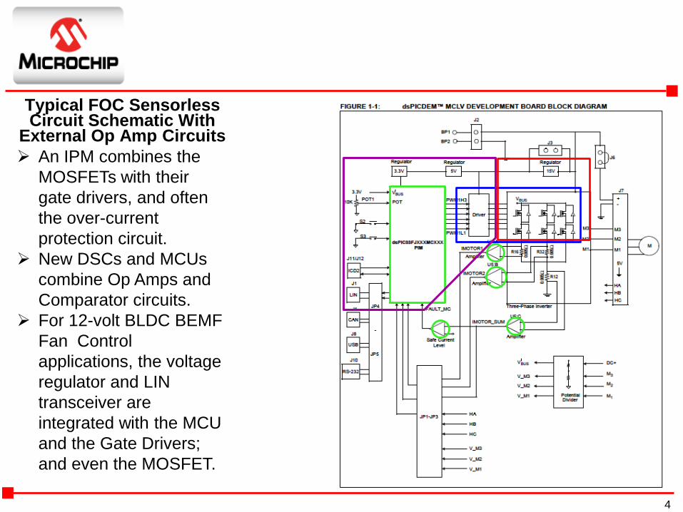
Typical FOC Sensorless Circuit Schematic With
External Op Amp Circuits
An IPM combines the
MOSFETs with their
gate drivers, and often
the over-current
protection circuit.
New DSCs and MCUs
combine Op Amps and
Comparator circuits.
For 12-volt BLDC BEMF
Fan Control
applications, the voltage
regulator and LIN
transceiver are
integrated with the MCU
and the Gate Drivers;
and even the MOSFET.
4
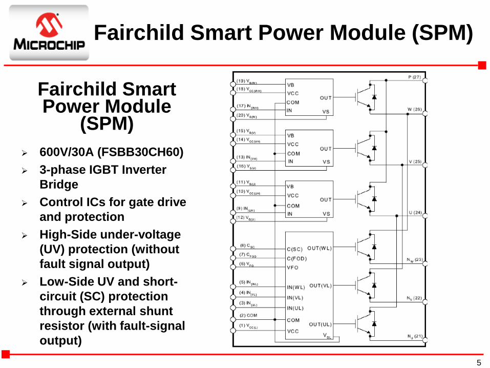
Fairchild Smart Power Module
(SPM)
600V/30A (FSBB30CH60)
3-phase IGBT Inverter
Bridge
Control ICs for gate drive
and protection
High-Side under-voltage
(UV) protection (without
fault signal output)
Low-Side UV and short-
circuit (SC) protection
through external shunt
resistor (with fault-signal
output)
Fairchild Smart Power Module (SPM)
5
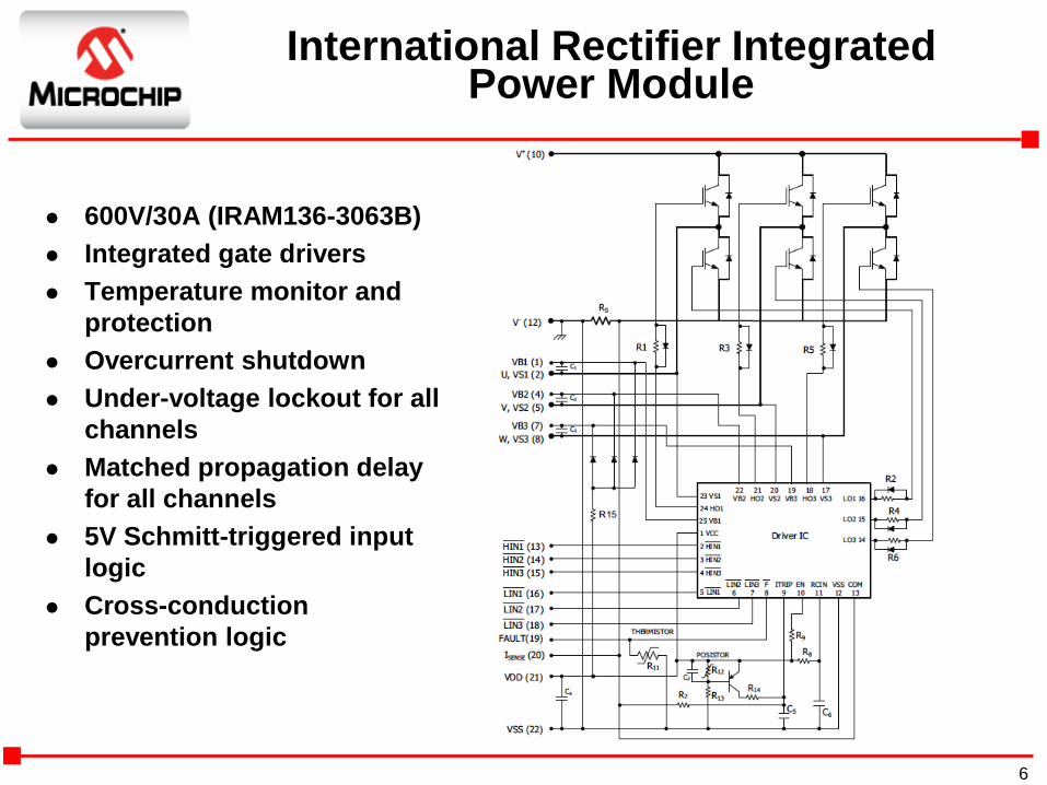
International Rectifier Integrated Power Module
600V/30A (IRAM136-3063B)
Integrated gate drivers
Temperature monitor and
protection
Overcurrent shutdown
Under-voltage lockout for all
channels
Matched propagation delay
for all channels
5V Schmitt-triggered input
logic
Cross-conduction
prevention logic
6

Melexis Sensorless BEMFBLDC Motor Controller
MLX81200 Features and Benefits:
18V/11 mA (0.2 Watts)
16-bit MCU with Flash memory
Gate drivers (NFET pre-driver with bootstrap)
Voltage regulator
RC/PLL oscillator
Integrated LIN or PWM transceiver
AEC-Q100 qualified up to 150°C ambient temperature
Very robust, wide dynamic range
Fast start up, accelerate and run under unknown load conditions
Low-noise operation
Block, trapezoidal and sinusoidal motor currents
Delta and star motor configuration (no star point required)
7

Microchip Integrated BLDC Motor Controllers
14V/36 mA (0.5 Watt)
Sinusoidal drive, for high efficiency and low acoustic noise
BEMF sensorless drive
Supports 2V to 14V power supplies (MTD6501C/D)
Speed control through PAM and/or PWM
Direction control pin (MTD6502B and MTD6505)
Motor speed output (FG)
Lockup protection and automatic recovery circuit (no external capacitor required)
Over-current limitation, short-circuit and over-temperature protection
Built-in thermal shutdown protection
No external tuning required
Boost mode (Optional BEMF pre-amplification in MTD6501D)
8
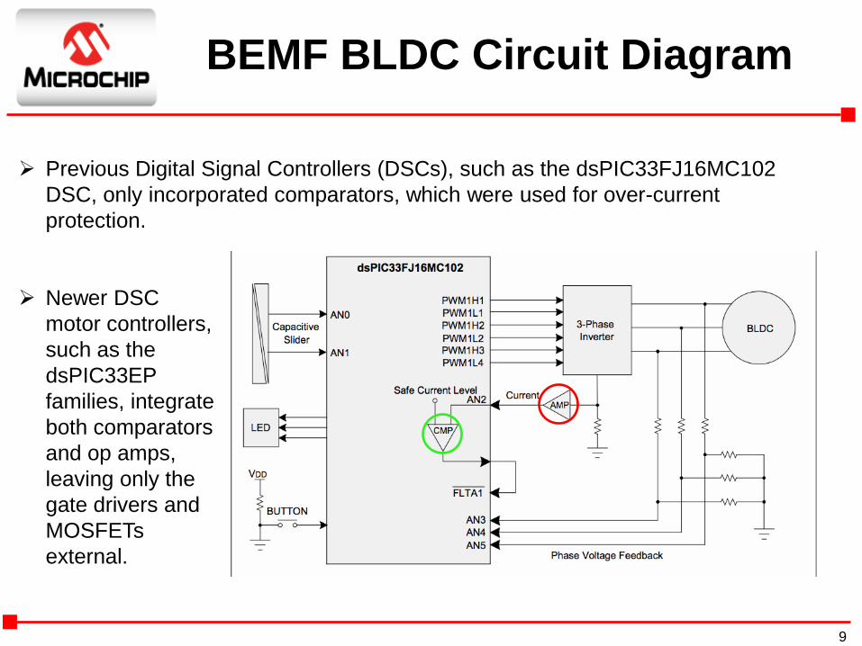
BEMF BLDC Circuit Diagram
Previous Digital Signal Controllers (DSCs), such as the dsPIC33FJ16MC102
DSC, only incorporated comparators, which were used for over-current
protection.
Newer DSC
motor controllers,
such as the
dsPIC33EP
families, integrate
both comparators
and op amps,
leaving only the
gate drivers and
MOSFETs
external.
9
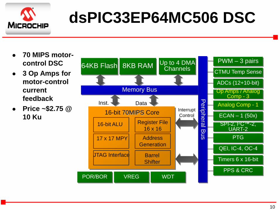
dsPIC33EP64MC506 DSC
70 MIPS motor-
control DSC
3 Op Amps for
motor-control
current
feedback
Price ~$2.75 @
10 KuInterrupt
Control
Inst. Data
64KB Flash 8KB RAM
POR/BOR VREG
Memory Bus
Perip
hera
l Bus
WDT
16-bit 70MIPS Core
16-bit ALU Register File
16 x 16
17 x 17 MPY Address
Generation
Barrel
Shifter
JTAG Interface
PWM – 3 pairs
Op Amps / Analog Comp - 3
ECAN – 1 (50x)
QEI, IC-4, OC-4
CTMU Temp Sense
Timers 6 x 16-bit
PPS & CRC
ADCs (12+10-bit)
Analog Comp - 1
SPI-2, I2C™-2, UART-2
PTG
Up to 4 DMA Channels
10
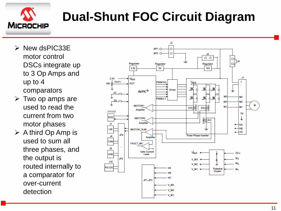
New dsPIC33E
motor control
DSCs integrate up
to 3 Op Amps and
up to 4
comparators
Two op amps are
used to read the
current from two
motor phases
A third Op Amp is
used to sum all
three phases, and
the output is
routed internally to
a comparator for
over-current
detection
Dual-Shunt FOC Circuit Diagram
11
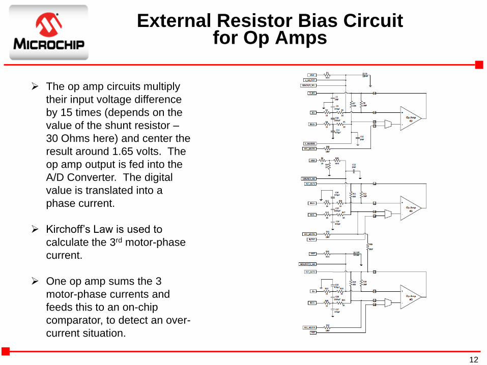
External Resistor Bias Circuitfor Op Amps
The op amp circuits multiply
their input voltage difference
by 15 times (depends on the
value of the shunt resistor –
30 Ohms here) and center the
result around 1.65 volts. The
op amp output is fed into the
A/D Converter. The digital
value is translated into a
phase current.
Kirchoff’s Law is used to
calculate the 3rd motor-phase
current.
One op amp sums the 3
motor-phase currents and
feeds this to an on-chip
comparator, to detect an over-
current situation.
12
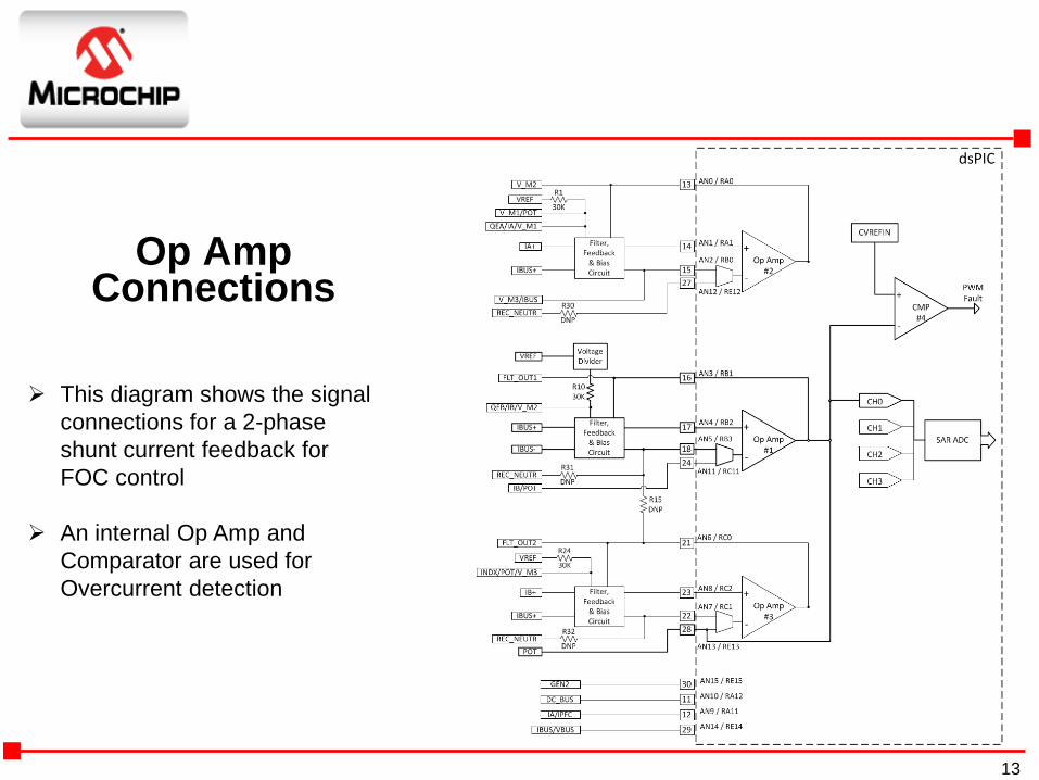
Op Amp Connections
This diagram shows the signal
connections for a 2-phase
shunt current feedback for
FOC control
An internal Op Amp and
Comparator are used for
Overcurrent detection
13
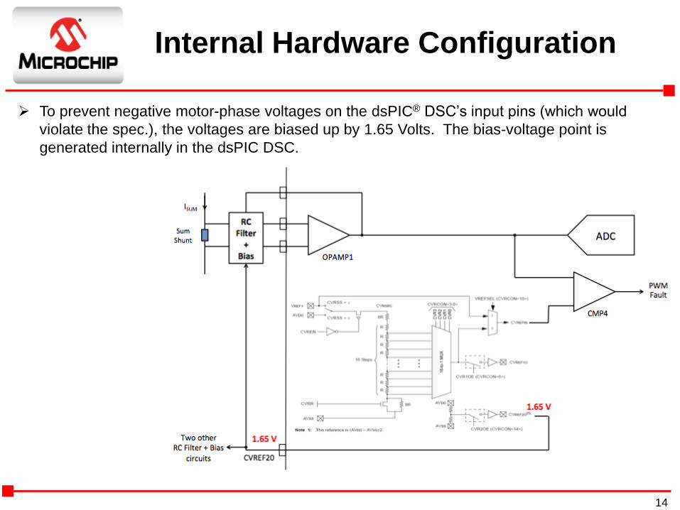
Internal Hardware Configuration
To prevent negative motor-phase voltages on the dsPIC® DSC’s input pins (which would
violate the spec.), the voltages are biased up by 1.65 Volts. The bias-voltage point is
generated internally in the dsPIC DSC.
14

Op Amp & Comparator Configuration
/* Set up CVREF */
CVRCON = 0;
CVRCONbits.CVR2OE = 1; // CVREF20 output to pin enabled for VREF of 1.65V
CVRCONbits.CVRR = 0; // 1/32 step size
CVRCONbits.CVR = 15; // CVREF = (0.1031)*CVR + 0.825
CVRCONbits.CVREN = 1; // CVREF circuit on
/* Comparator enabled as op amp, op amp inputs CxIN1+/- */
CM1CON = 0x8C00;
CM2CON = 0x8C00;
CM3CON = 0x8C00;
/* Set up CMP4 */
CM4CON = 0;
CM4CONbits.CPOL = 0; // Comparator output non-inverted
CM4CONbits.EVPOL = 2; // Event generated on Low-to-high transition of
comparator output
CM4CONbits.CREF = 1; // VIN+ input connects to internal CVREFIN voltage
CM4CONbits.CCH = 1; // VIN- input connects to CMP1 (source Ibus)
CM4CONbits.COE = 1; // Comparator output enabled
CM4CONbits.CON = 1; // Enable comparator
15
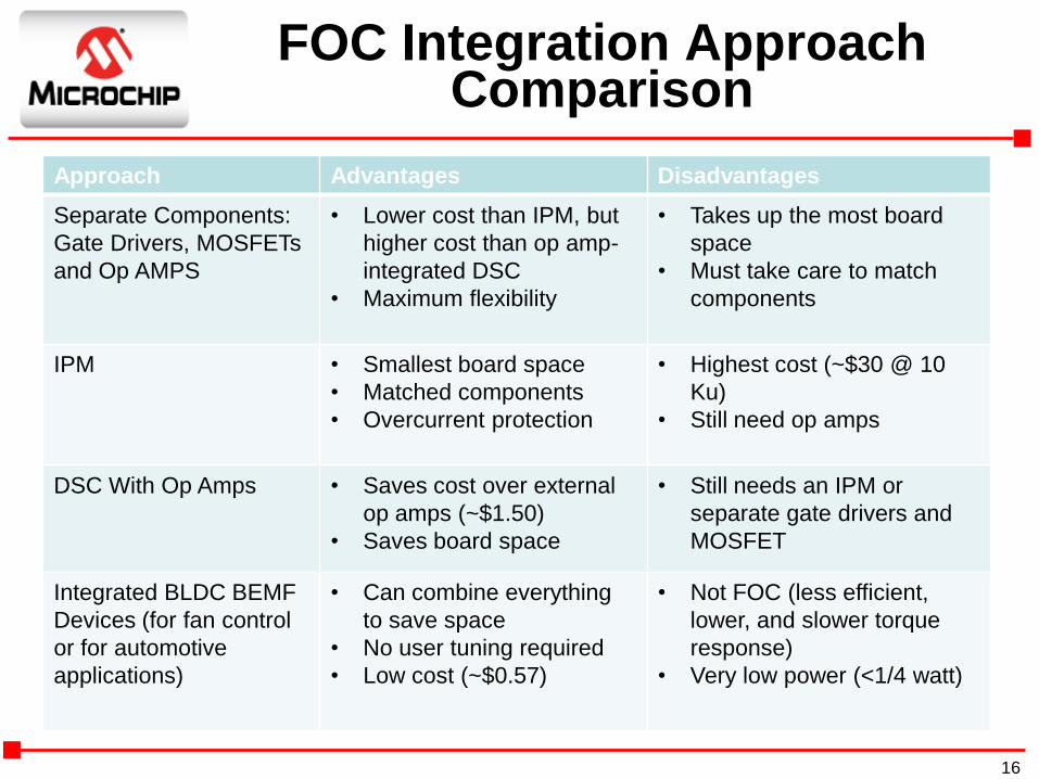
FOC Integration Approach Comparison
Approach Advantages Disadvantages
Separate Components:
Gate Drivers, MOSFETs
and Op AMPS
• Lower cost than IPM, but
higher cost than op amp-
integrated DSC
• Maximum flexibility
• Takes up the most board
space
• Must take care to match
components
IPM • Smallest board space
• Matched components
• Overcurrent protection
• Highest cost (~$30 @ 10
Ku)
• Still need op amps
DSC With Op Amps • Saves cost over external
op amps (~$1.50)
• Saves board space
• Still needs an IPM or
separate gate drivers and
MOSFET
Integrated BLDC BEMF
Devices (for fan control
or for automotive
applications)
• Can combine everything
to save space
• No user tuning required
• Low cost (~$0.57)
• Not FOC (less efficient,
lower, and slower torque
response)
• Very low power (<1/4 watt)
16

Typical Stepper-Motor Circuit Diagram
An IPM combines the MOSFETs with their gate drivers, and often the over-current protection circuit.
New DSCs and MCUs combine op amps (used for current-mode control) and comparators (used for over-current protection)
For 12-volt automotive-control applications, the LIN transceiver is integrated with the MCU, gate drivers, and the MOSFETS.
17
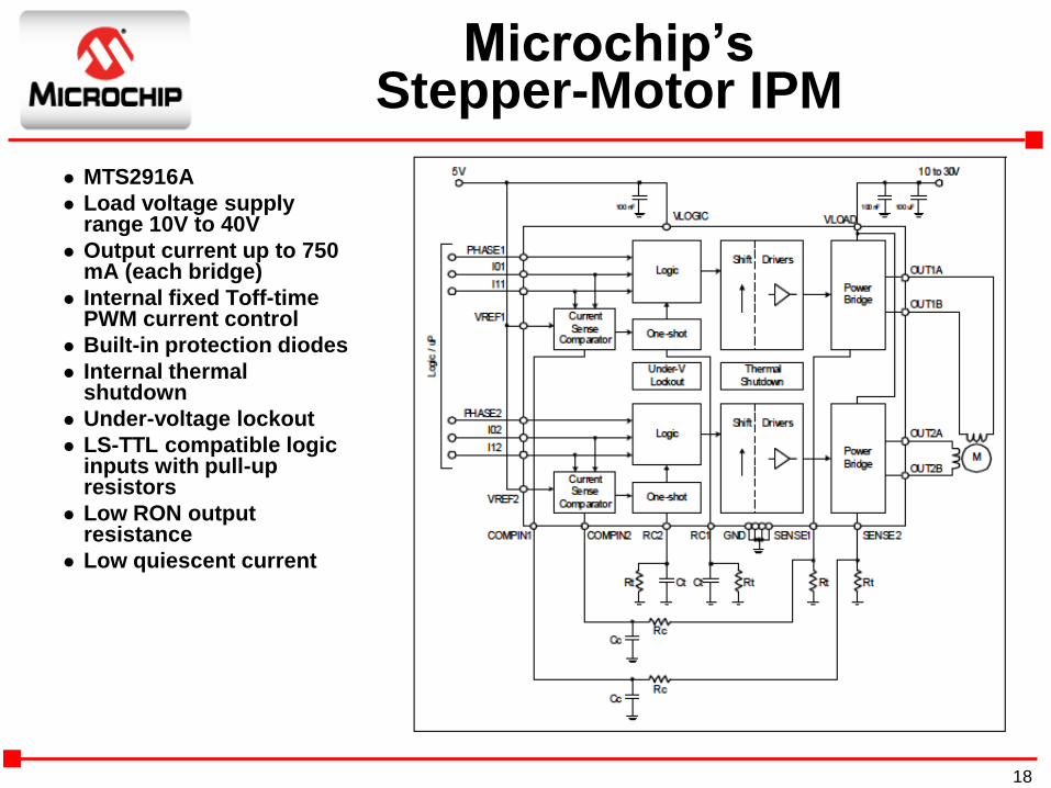
Microchip’sStepper-Motor IPM
MTS2916A
Load voltage supply range 10V to 40V
Output current up to 750 mA (each bridge)
Internal fixed Toff-time PWM current control
Built-in protection diodes
Internal thermal shutdown
Under-voltage lockout
LS-TTL compatible logic inputs with pull-up resistors
Low RON output resistance
Low quiescent current
18
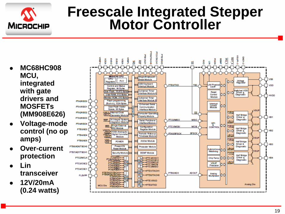
Freescale Integrated Stepper Motor Controller
MC68HC908 MCU, integrated with gate drivers and MOSFETs (MM908E626)
Voltage-mode control (no op amps)
Over-current protection
Lin transceiver
12V/20mA (0.24 watts)
19

Stepper Integration Approach Comparison
Approach Advantages Disadvantages
Separate
Components: Gate
Drivers, MOSFETs
and Op AMPS
• Lower cost than IPM, but higher cost than
op amp-integrated DSC
• Maximum flexibility
• Takes up the most board
space
• Must take care to match
components
Stepper Motor IPM • Smallest board space
• Matched components
• Overcurrent Protection
• Higher cost (~$0.75 @ 10 Ku)
• Still need op amps for current-
mode control
• Still need MCU
• Limited micro-stepping
DSC with Op Amps
and Comparators
• Saves cost over external op
amps/comparators (~$1.50)
• Saves board space
• Micro-stepping (down to 1/256)
• Voltage & current control mode options
• Still needs Gate Drivers and
MOSFETS
Integrated Stepper
Motor Driver (for
automotive
applications)
• Can combine everything except voltage
regulators to save space
• No user tuning required
• Voltage-control mode, only
(slower, noisier, less efficient)
• Very low power (<1/4 watt)
20
Summary
Three approaches to the integration problem: Integrated Power Module (IPM) approach—
combine all the high-voltage components
Integrated DSC/MCU approach—combine all the low-voltage components
Integrated Driver approach—combine some of (or all of) the components for a low-power BLDC or Stepper motor solution
Motor-drive design engineers and the end customers will continue to benefit from lower costs, simplified circuit designs and more compact solutions.
Note: The Microchip name and logo, and dsPIC are registered trademarks of Microchip Technology Inc. in the U.S.A. and other countries.
All other trademarks mentioned herein are property of their respective companies.
21