Embed Size (px)
Citation preview

2014-03 002.001 ENG
Head Office & Factory153, Jeongdong-ro, Seongsan-gu, Changwon-si, Gyeongsangnam-do
Tel +82 55 280 9206, 9299 Fax +82 55 210 9804
www.wiamachine.co.kr
Overseas Sales Team16F, 37, Cheoldobangmulgwan-ro, Uiwang-si, Gyeonggi-do
Tel +82 31 593 8173
F510M/660MHYUNDAI WIA Vertical Machining Center for Mold Machining
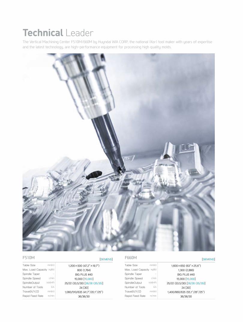
The Vertical Machining Center F510M/660M by Huyndai WIA CORP, the national (Kor) tool maker with years of expertise and the latest technology, are high-performance equipment for processing high quality molds.
Technical Leader
F510Mmm(in)
kg(lb)
-
r/min
kW(HP)
EA
mm(in)
m/min
1,200×500 (47.2″×19.7″)
800 (1,764)
BIG PLUS #40
15,000 [15,000]
25/22 (33.5/30) [26/26 (35/35)]
24 [30]
1,060/510/635 (41.7″/20.1″/25″)
36/36/30
Table Size
Max. Load Capacity
Spindle Taper
Spindle Speed
SpindleOutput
Number of Tools
Travel(X/Y/Z)
Rapid Feed Rate
F660Mmm(in)
kg(lb)
-
r/min
kW(HP)
EA
mm(in)
m/min
1,600×650 (63″×25.6″)
1,300 (2,866)
BIG PLUS #40
15,000 [15,000]
25/22 (33.5/30) [26/26 (35/35)]
24 [30]
1,400/660/635 (55.1″/26″/25″)
36/36/30
Table Size
Max. Load Capacity
Spindle Taper
Spindle Speed
SpindleOutput
Number of Tools
Travel(X/Y/Z)
Rapid Feed Rate
[SIEMENS] [SIEMENS]
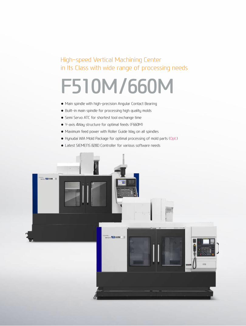
High-speed Vertical Machining Centerin Its Class with wide range of processing needs
F510M/660M● Main spindle with high-precision Angular Contact Bearing
● Built-in main spindle for processing high quality molds
● Semi Servo ATC for shortest tool exchange time
● Y-axis 4Way structure for optimal feeds (F660M)
● Maximum feed power with Roller Guide Way on all spindles
● Hynudai WIA Mold Package for optimal processing of mold parts (Opt.)
● Latest SIEMENS 828D Controller for various software needs
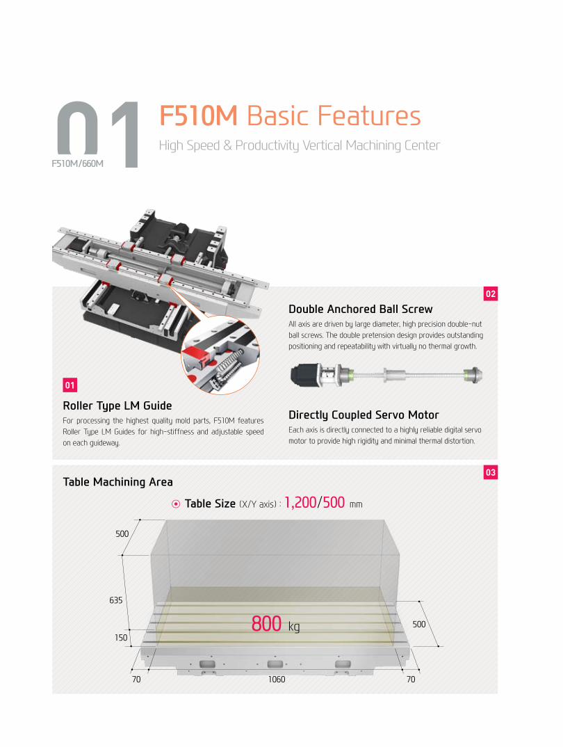
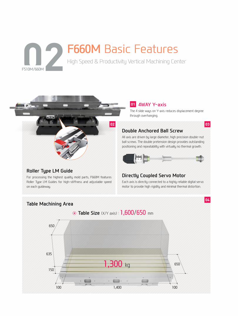
01 F510M Basic FeaturesHigh Speed & Productivity Vertical Machining Center
F510M/660M
Roller Type LM GuideFor processing the highest quality mold parts, F510M features Roller Type LM Guides for high-stiffness and adjustable speed on each guideway.
Table Machining Area
Double Anchored Ball ScrewAll axis are driven by large diameter, high precision double-nut ball screws. The double pretension design provides outstanding positioning and repeatability with virtually no thermal growth.
Directly Coupled Servo MotorEach axis is directly connected to a highly reliable digital servo motor to provide high rigidity and minimal thermal distortion.
03
02
01
500
635
150
70 1060 70
500800 kg
◉ Table Size (X/Y axis) : 1,200/500 mm
04+
05
F5
10M
/660
MVe
rtic
al M
achi
ning
Cen
ter
HYU
ND
AI W
IAM
ACH
INE
TOO
L
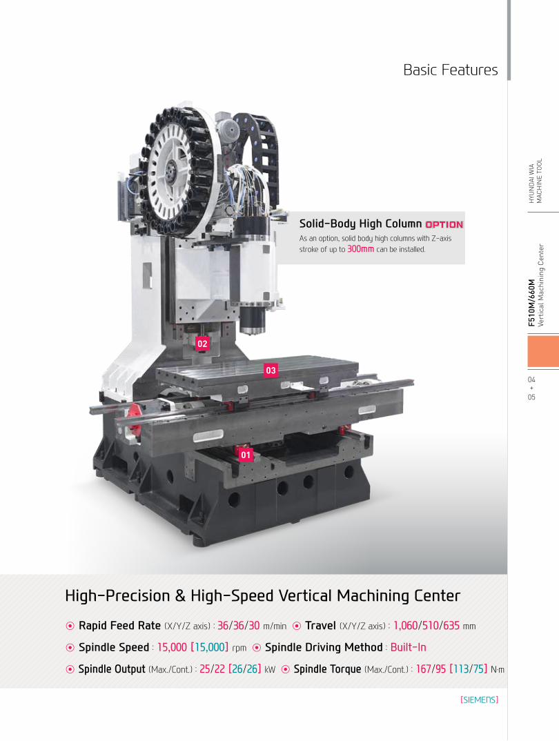
Basic Features
01
03
02
Solid-Body High ColumnAs an option, solid body high columns with Z-axis stroke of up to 300mm can be installed.
◉ Rapid Feed Rate (X/Y/Z axis) : 36/36/30 m/min ◉ Travel (X/Y/Z axis) : 1,060/510/635 mm
◉ Spindle Speed : 15,000 [15,000] rpm ◉ Spindle Driving Method : Built-In
◉ Spindle Output (Max./Cont.) : 25/22 [26/26] kW ◉ Spindle Torque (Max./Cont.) : 167/95 [113/75] N.m
High-Precision & High-Speed Vertical Machining Center
[SIEMENS]
02 F660M Basic FeaturesHigh Speed & Productivity Vertical Machining Center
F510M/660M
4WAY Y-axisThe 4 slide ways on Y-axis reduces displacement degree through overhanging.
Table Machining Area
Double Anchored Ball ScrewAll axis are driven by large diameter, high precision double-nut ball screws. The double pretension design provides outstanding positioning and repeatability with virtually no thermal growth.
Directly Coupled Servo MotorEach axis is directly connected to a highly reliable digital servo motor to provide high rigidity and minimal thermal distortion.
04
0302
Roller Type LM GuideFor processing the highest quality mold parts, F660M features Roller Type LM Guides for high-stiffness and adjustable speed on each guideway.
650
635
150
100 1,400 100
6501,300 kg
◉ Table Size (X/Y axis) : 1,600/650 mm
01
06+
07
F5
10M
/660
MVe
rtic
al M
achi
ning
Cen
ter
HYU
ND
AI W
IAM
ACH
INE
TOO
L
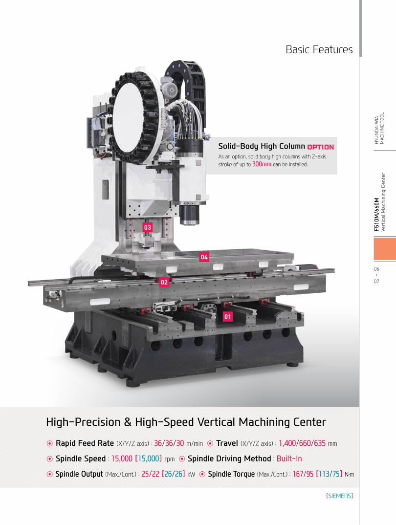
Basic Features
01
03
04
02
Solid-Body High ColumnAs an option, solid body high columns with Z-axis stroke of up to 300mm can be installed.
◉ Rapid Feed Rate (X/Y/Z axis) : 36/36/30 m/min ◉ Travel (X/Y/Z axis) : 1,400/660/635 mm
◉ Spindle Speed : 15,000 [15,000] rpm ◉ Spindle Driving Method : Built-In
◉ Spindle Output (Max./Cont.) : 25/22 [26/26] kW ◉ Spindle Torque (Max./Cont.) : 167/95 [113/75] N.m
High-Precision & High-Speed Vertical Machining Center
[SIEMENS]
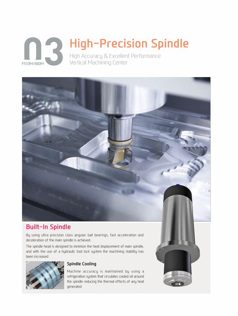
03 High-Precision SpindleHigh Accuracy & Excellent PerformanceVertical Machining CenterF510M/660M
Built-In SpindleBy using ultra precision class angular ball bearings, fast acceleration and deceleration of the main spindle is achieved.
The spindle head is designed to minimize the heat displacement of main spindle, and with the use of a hydraulic tool lock system the machining stability has been increased
Spindle Cooling
Machine accuracy is maintained by using a refrigeration system that circulates cooled oil around the spindle reducing the thermal effects of any heat generated
08+
09
F5
10M
/660
MVe
rtic
al M
achi
ning
Cen
ter
HYU
ND
AI W
IAM
ACH
INE
TOO
L
Spindle
Spindle Thru CoolantThrough the spindle coolant is available. This is particularly useful for deep hole drilling and helps increase tool life and decrease cycle time.
2 Faces SpindleThe Big Plus spindle system (BBT40) provides dual contact between the spindle face and the flange face of the tool holder. This greatly increase tool rigidity, reduces run out and adds significant productivity to yourmachining applications
❖ The increase in standard diameter improves stiffness and ATC interactive precision, and Z-axis displacement prevention further extends tool life.
BBT
HSK
CAT
Tool Holders
20 bar / 30 bar / 70 bar
Before Clamping After Clamping
Clamping
Non Contact Contact
Axial Movement is Important for Face Contact
POWER(kW) Torque(N.m) POWER(kW) Torque(N.m)
Spindle Speed (r/min)
0
167N.m (S3 25%)
F510M/660M 12,000rpm FANUC 15,000rpm
25
2218.5
15
167
118
95
4.84.2
12,0005,0003,5001,5001,060
95N.m (Cont.)
25kW (S2, 15min)
22kW (Cont.) 22kW (Cont.)25kW (S2, 15%) 26kW (25%) 26kW (Cont.)
75N.m (Cont.)
Spindle Speed (r/min)
0
25
22
167
95
15,00012,5005,0003,5001,5001,060
11818.5
15
4842
167N.m (S3 25%)
118N.m (S2 15min)
95N.m (Cont.)
POWER(kW) Torque(N.m)
SIEMENS 15,000rpm
Spindle Speed (r/min)
0
26
75
15,0003,300
113113N.m (25%)
Spindle Output/Torque Diagram
04 ATC & MagazineHigh Productivity Achieved with High Rigidity, Accuracy MachiningF510M/660M
◉ No. of Tool : 24 [30] EA
◉ Tool Shank : BBT40◉ Max. Tool Dia. (W.T/W.O) : Ø90/Ø150
◉ Max. Tool Length : 300 mm
◉ Max. Tool Weight : 8 kg
◉ Tool Selection Method : Random
10+
11
F5
10M
/660
MVe
rtic
al M
achi
ning
Cen
ter
HYU
ND
AI W
IAM
ACH
INE
TOO
L
Peripheral Device
MagazineThe tool magazine holds twenty four (24) tools as standard and thirty (30) tools as an option.Random access allows for pre-staging of tools for faster tool changes and increased productivity
Servo ATCPosition control through Twin Arm ATC on Servo Motors has been improved drastically. In addition, tool exchanging has become easier, reducing Specific cutting time tremendously.
24 Tool Magazine
30 Tool Magazine
◉ ATC Speed Improvement
21% reduction 9.5% reduction
Before
After
Before
After
1.9 sec 4.1 sec
1.5 sec 3.9 sec
F660M (Tool to Tool) F660M (Chip to Chip)
21% reduction 9.5% reduction
Before
After
Before
After
1.9 sec 4.2 sec
1.5 sec 3.8 sec
F510M (Tool to Tool) F510M (Chip to Chip)
05 Machining CapabilityExcellent Performance, High Accuracy CuttingVertical Machining CenterF510M/660M
Machining
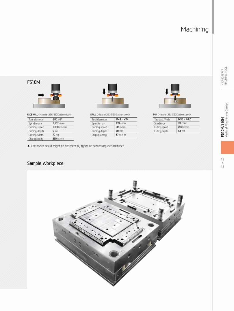
❖ The above result might be different by types of processing circumstance
12+
13
F5
10M
/660
MVe
rtic
al M
achi
ning
Cen
ter
HYU
ND
AI W
IAM
ACH
INE
TOO
L
FACE MILL 〈Material〈JIS〉:S45C(Carbon steel)〉
Tool diameterSpindle rpmCutting speedCutting depthCutting widthChip quantity
Ø80 x 6F1,137 r/min
1,000 mm/min
5 mm
70 mm
350 cc/min
DRILL 〈Material〈JIS〉:S45C(Carbon steel)〉
Tool diameterSpindle rpmCutting speedCutting depthChip quantity
Ø43 x MT4
199 r/min
39 m/min
60 mm
57 cc/min
TAP. 〈Material〈JIS〉:S45C(Carbon steel)〉
Tap spec./PitchSpindle rpmCutting speedCutting depth
M36 x P4.0
70 r/min
280 m/min
54 mm
F510M
Sample Workpiece
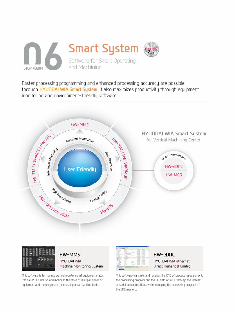
Intelligent Machining
Machine Monitoring
High Precision
High Productivity Energy Savin
g
HW-TM | HW-MCS | HW-A
FC
HW-TOM | HW-WCM
HW-ESS
User Friendly
HW-MMSHW-TDC | HW
-WARM
UP
HYUNDAI WIA Smart System for Vertical Machining Center
User Convenience
HW-eDNC
HW-MCG
Faster processing programming and enhanced processing accuracy are possible through HYUNDAI WIA Smart System. It also maximizes productivity through equipment monitoring and environment-friendly software.
HW-eDNCHYUNDAI WIA ethernet Direct Numerical Control
This software transmits and receives the CNC of processing equipment, the processing program and the NC data on a PC through the internet or serial communications, while managing the processing program of the CNC memory.
HW-MMSHYUNDAI WIAMachine Monitoring System
This software is for remote control monitoring of equipment status (mobile, PC.) It checks and manages the state of multiple pieces of equipment and the progress of processing on a real time basis.
06 Smart SystemSoftware for Smart Operating and MachiningF510M/660M
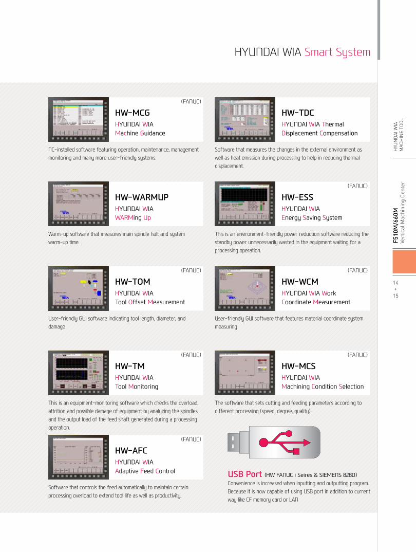
HW-TDCHYUNDAI WIA Thermal Displacement Compensation
Software that measures the changes in the external environment as well as heat emission during processing to help in reducing thermal displacement.
HW-ESSHYUNDAI WIAEnergy Saving System
This is an environment-friendly power reduction software reducing the standby power unnecessarily wasted in the equipment waiting for a processing operation.
(FANUC)
HW-TMHYUNDAI WIATool Monitoring
This is an equipment-monitoring software which checks the overload, attrition and possible damage of equipment by analyzing the spindles and the output load of the feed shaft generated during a processing operation.
(FANUC)
HW-MCGHYUNDAI WIAMachine Guidance
NC-installed software featuring operation, maintenance, management monitoring and many more user-friendly systems.
(FANUC)
HW-WARMUPHYUNDAI WIAWARMing Up
Warm-up software that measures main spindle halt and system warm-up time.
HW-TOMHYUNDAI WIATool Offset Measurement
User-friendly GUI software indicating tool length, diameter, and damage
(FANUC)
HW-WCMHYUNDAI WIA Work Coordinate Measurement
User-friendly GUI software that features material coordinate system measuring
(FANUC)
HW-AFCHYUNDAI WIAAdaptive Feed Control
Software that controls the feed automatically to maintain certain processing overload to extend tool life as well as productivity.
(FANUC)
HW-MCSHYUNDAI WIAMachining Condition Selection
The software that sets cutting and feeding parameters according to different processing (speed, degree, quality)
(FANUC)
HYUNDAI WIA Smart System
USB Port (HW FANUC i Seires & SIEMENS 828D)Convenience is increased when inputting and outputting program. Because it is now capable of using USB port in addition to current way like CF memory card or LAN
14+
15
F5
10M
/660
MVe
rtic
al M
achi
ning
Cen
ter
HYU
ND
AI W
IAM
ACH
INE
TOO
L
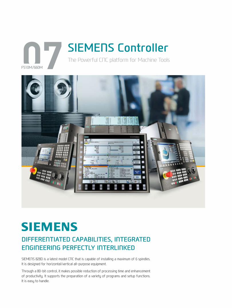
07 SIEMENS ControllerThe Powerful CNC platform for Machine Tools
F510M/660M
DIFFERENTIATED CAPABILITIES, INTEGRATED ENGINEERING PERFECTLY INTERLINKEDSIEMENS 828D is a latest model CNC that is capable of installing a maximum of 6 spindles. It is designed for horizontal/vertical all-purpose equipment.
Through a 80-bit control, it makes possible reduction of processing time and enhancement of productivity. It supports the preparation of a variety of programs and setup functions. It is easy to handle.
•Dialogue-type programming, simple and convenient • Effective specifications for small quantity
batch production• Step-by-step operation possible without
knowledge of the DIN/ISO code
Shop Mill
• 3-dimensional (3D) confirmation (an option) of the completed processing configuration of the NC program is possible.
• Offers standards for 2-dimensional simulation (2D) • Possible to confirm the simulation of the NC
grogram during processing.
3D Simulation
• Easy to install/uninstall an option (Example: barfeeder and chip conveyor, etc.)
• Possible to install in one motion without revision of individual perimeters.
• A spate list is unnecessary as option items are indicated with letters.
Easy Extend
Easy input/output of a program is possible as a USB memory card, a CF memory card and LAN can all be used.
Variable Communication Port
RJ 45 Ethernet
USB 2.0
Compact Flash Card
If the ISO Dialect (G291) is ordered, JIS-based G-code programs can be used. (Standard)
SIEMENS Technology SIEMENS Communication
ISO CodeProgramming
16+
17
F5
10M
/660
MVe
rtic
al M
achi
ning
Cen
ter
HYU
ND
AI W
IAM
ACH
INE
TOO
L
SIEMENS
08 Mold PackagePowerful Mold Package, HYUNDAI-WIA Mold All in OneF510M/660M
HWM ALL-IN-ONETo aid in the machining of molds, the Hyundai WIA Mold package is applied as a standard feature for F510M/660M machines. (FANUC 31i-A Only)
This ensures accurate and high quality surface finishes and contouring.
Mold Package Option (FANUC F31i-A / SIEMENS 828D)
1 Package 2 Package 3 Package 4 Package S Package (FANUC) (FANUC) (FANUC) (FANUC) (SIEMENS)
● ◦ ◦ ◦ ● ● ◦ ◦ ◦ ● ◦ ◦ ◦ ● ● ◦ ◦ ◦ ●
● ◦ ◦ ◦ ● ● ◦ ◦ ◦ ● ● ◦ ◦ ◦ ● ◦ ◦ ◦
HWM ALL IN ONE
AICCⅡ Package
Mdynamic (Advanced surface)
S/W : HW-MCS, HW-AFC
Auto Power Off
Spindle Heat Distortion
Compensation Device (8 Channels)
Cutting Air Blow
Auto Tool Measuring Device
Roller Type LM Guideway
Data Server 1GB
200 block
600 block
1,000 block
●: Standard ○: Option
Advanced Surface
➊ High Speed Contouring Control (AICCⅡ : 200 Block) Recognizes NC Data prior to the current processing phase
➋ Optimal S/W (FANUC Models) HW-MCS (Selectable Process Conditions) HW-AFC (Adapive Feed Control)
➌ Automatic Power Cut Off Device Useful for complicated processing that requires long hours
➏ Contact Probe(RENISHAW TS27R) Detects and sets tool length, and wear(Graphic User Interface included)
➍ Spindle Heat Distortion Compensation Device (8 Channels) Maintains temperature on the main spindle (heat sensor)
➎ Cutting Air Blow No need for cutting oil during mold processing
Speed
Speed
SINUMERIK + SINAMICS 80bit NANO FP Accuracy
Machining Time : 48 min
Unbalanced Velocity
Machining Time : 33 min
Balanced Velocity
• Advanced Surface software for high speed, high-accuracy mold processing
• 80-bit floating-point calculation supported – Able to calculate numbers less than a nanometer
• A brand new filter for speed and acceleration control – Improves upon the problems of intensity of illumination due to irregular CAM data
• Standard jerk-restriction function to ease deceleration impact – Minimized vibration and high-speed deceleration
• Standard feed-forward function for speed control – Improves contouring accuracy by correcting the following error before setting point output
18+
19
F5
10M
/660
MVe
rtic
al M
achi
ning
Cen
ter
HYU
ND
AI W
IAM
ACH
INE
TOO
L
Mold Package
User ConvenienceVarious Devices for User Friendly
Hyd. Supply UnitInstead of the standard hydraulic supply unit, an optional fixture unit can bring the pressure up to 100 bar, maximizing the clamping force on the fixture.
NC Rotary TableThe feeder on the Machining Center is orthogonal, making it possible to process with 5 axes with rotary table.
U-CenterWith U-Center, both external and internal diameter turning become possible, allowing for a wide range of variety in products.
Measuring Device
Hyd. Device
Precision Device
09F510M/660M
Touch SensorWork piece coordinate values can be set automatically using the optional spindle probe.
TLM - Laser & TouchTool lengths and diameters can be set automatically using the optional tool setter. This can also be used to monitor tool wear and detect broken tools.
Laser Type
Touch Type
Optional
20+
21
F5
10M
/660
MVe
rtic
al M
achi
ning
Cen
ter
HYU
ND
AI W
IAM
ACH
INE
TOO
L
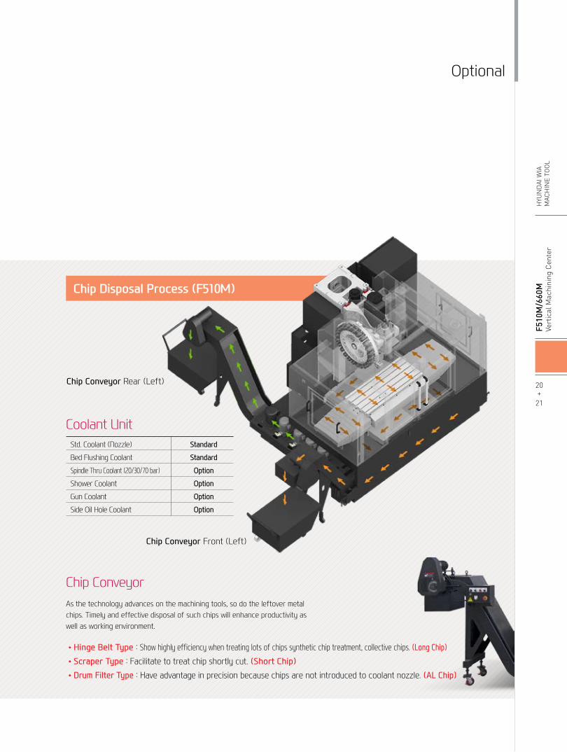
Std. Coolant (Nozzle)
Bed Flushing Coolant
Spindle Thru Coolant (20/30/70 bar)
Shower Coolant
Gun Coolant
Side Oil Hole Coolant
Standard
Standard
Option
Option
Option
Option
Coolant Unit
Chip Disposal Process (F510M)
•Hinge Belt Type : Show highly efficiency when treating lots of chips synthetic chip treatment, collective chips. (Long Chip)•Scraper Type : Facilitate to treat chip shortly cut. (Short Chip)•Drum Filter Type : Have advantage in precision because chips are not introduced to coolant nozzle. (AL Chip)
As the technology advances on the machining tools, so do the leftover metal chips. Timely and effective disposal of such chips will enhance productivity as well as working environment.
Chip Conveyor Front (Left)
Chip Conveyor Rear (Left)
Chip Conveyor
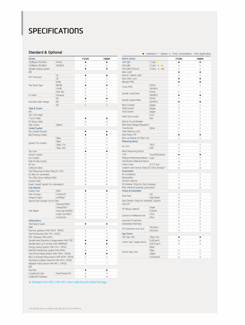
F510M F660M ● ● ○ ○ ○ ○ ● ● ○ ○ ● ● ● ● ○ ○ - - ○ ○ ● ● ○ ○ ● ● ○ ○ ○ ○ ○ ○ ○ ○ ○ ○ ○ ○ ☆ ☆ ○ ○ ○ ○ ● ● ○ ○ ○ ○ ○ ○ ○ ○ ● ● ○ ○ ☆ ☆ ○ ○ ☆ ☆ ○ ○ ○ ○ ○ ○ ○ ○ ☆ ☆ ○ ○ ☆ ☆ ☆ ☆ ☆ ☆ ○ ○ ☆ ☆ ○ ○ ☆ ☆ ○ ○ ☆ ☆ ○ ○ ○ ○ ● ● ☆ ☆ ☆ ☆ - - ○ ○ ○ ○ ☆ ☆
Call LightCall LightCall Light & BuzzerWork LightElectric Cabinet LightDoor Inter-LockRemote MPG
3 Axis MPG
Spindle Load Meter
Spindle Speed Meter
Work CounterTotal CounterTool Counter
Multi Tool Counter
Electric Circuit BreakerAVR (Auto Voltage Regulator)TransformerFlash Memory CardAuto Power OffBack up Module for Black outMeasuring Device
Air Zero
Work Measuring DeviceTLM(Marposs/Renishaw/Bloom)Tool Broken Detective DeviceLinear ScaleCoolant Level Sensor (Only for Chip Conveyor)EnviornmentAir ConditionerDehumidifierOil Mist CollectorOil Skimmer (Only for Chip Conveyor)MQL (Minimal Quantity Lubrication)Fixture & Automation
Auto Door
Auto Shutter (Only for Automatic System)Sub O/P
NC Rotary TableI/F
Control of Additional Axis
External M Code 4eaAutomation Interface
I/O Extension (In & Out)
Hyd. DeviceStd. Hyd. Unit
Center Hyd. Supply Device
Fixture Hyd. Unit
1 Color : ■3 Color : ■■■3 Color : ■■■B
FANUCSIEMENSFANUCSIEMENSFANUCSIEMENSDigitalDigitalDigital6 EA9EA
35kVA
TACOSMC
Touch(Renishaw)Laser
X/Y/Z Axis
Std.High Speed
SingleChannel1Axis2Axis
16Contact32Contact
70bar/14ℓ2x3(6 port)2x5(10 port)45bar70bar100barCustomized
Standard & Optional
15,000rpm (25/22kW)15,000rpm (26/26kW) Spindle Cooling SystemATC
ATC Extension
Tool Shank Type
U-Center
Stud Bolt Collet Change
Table & ColumnAPCTAP TYPE PalletT-SLOT PalletNC Rotary TableHigh ColumnCoolant SystemStd. Coolant (Nozzle)Bed Flushing Coolant
Spindle Thru Coolant
Top CoverShower CoolantGun CoolantSide Oil Hole CoolantAir GunCutting Air BlowTool Measuring Air Blow (Only for TLM)Air Blow for AutomationThru MQL Device (Without MQL)Coolant ChillerPower Coolant System (For Automation)Chip DisposalCoolant TankChip Conveyor(Hinge/Scraper)Special Chip Conveyor (Drum Filter)
Chip Wagon
Safety DeviceTotal Splash GuardS/WMachine guidance (HW-MCG) : FANUCTool Monitoring (HW-TM) : FANUCDNC Software (HW-eDNC)Spindle Heat Distortion Compensation (HW-TDC)Spindle Warm up Function (HW-WARMUP)Energy Saving System (HW-ESS) : FANUCMachine Monitoring System (HW-MMS)Tool Offset Measurement (HW-TOM) : FANUCWork Coordinate Measurement (HW-WCM) : FANUCMachining Condition Selection (HW-MCS) : FANUCAdaptive Feed Control (HW-AFC) : FANUCETCTool BoxCustomized ColorCAD&CAM Software
FANUCSIEMENS
2430BT40BBT40CAT40HSK-A63D'andrea45°60°90°
300mm
20bar30bar70bar, 15ℓ70bar, 30ℓ
350ℓFront(Left)Left(Rear)
Standard(180ℓ)Swing(200ℓ)Swing Large Size(290ℓ)Large Size(330ℓ)Customized
Need Munsel NO.
Spindle Electric Device
● : Standard ○ : Option ☆ : Prior Consultation - Non Application
F510M F660M ● ● ○ ○ ● ● ● ● ○ ○ ○ ○ ● ● ○ ○ ○ ○ ○ ○ ● ● ○ ○ ○ ○ - - - - ● ● ☆ ☆ ○ ○ ● ● ● ● ○ ○ ○ ○ ○ ○ ☆ ☆ ● ● ○ ○ ○ ○ ○ ○ ○ ○ ○ ○ ○ ○ ☆ ☆ ☆ ☆ ☆ ☆ ☆ ☆ ● ● ○ ○ ○ ○ ☆ ☆ ○ ○ ○ ○ ○ ○ ☆ ☆ ☆ ☆ ● ● ○ ○ ○ ○ ○ ○ ● ● ● ● ○ ○ ☆ ☆ ● ● ○ ○ ○ ○ ○ ○ ● ● ☆ ☆ ☆ ☆
The specifications as above will only serve as a reference.
SPECIFICATIONS
❖ Standard HW-MCS, HW-AFC when selecting the Mold Package
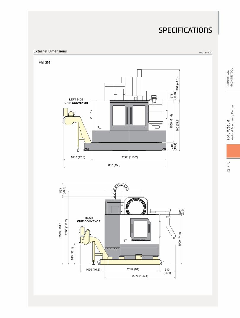
unit : mm(in)External Dimensions
F510M
1085 (42.7)
846 (33.3)
1036 (40.8)
755
(29.
7)
548
(21.
6)
LEFT SIDECHIP CONVEYOR
LEFT SIDECHIP CONVEYOR
REARCHIP CONVEYOR
REARCHIP CONVEYOR
1950
(76.
8)
2450 (96.5) 90 (3.5)315(12.4)1167 (45.9) 2540 (100)
884
(34.
8)
1860 (73.2) 34 (1.3)2979 (117.3)
1163
(45.
8)
2287
(90)
2498
(98.
3)
2833
(111
.5)
1950
(76.
8)60 (2.4
)
618(24.3)
LEFT SIDECHIP CONVEYOR
REARCHIP CONVEYOR
2356 (92.8)
3202 (126.1)
3118 (122.8)
842
(33.
1)
2110
(83.
1)
2475
(97.
4)
2810
(110
.6)
3500 (137.8)
4504 (177.3)
350
(13.
8)17
05 (6
7.1)
2055
(80.
9)
1004 (39.5)
1900
(74.
8)20
5(8
.1)
815
(32.
1)
2800
(110
.2)
2573
(101
.3)
523
(20.
6)
340
(13.
4)15
60 (6
1.4)
1197
(47.
1)19
00 (7
4.8)
378
(14.
9)
2800 (110.2)1087 (42.8)
3887 (153)
2057 (81)
2670 (105.1)
613(24.1) 1085 (42.7)
846 (33.3)
1036 (40.8)
755
(29.
7)
548
(21.
6)
LEFT SIDECHIP CONVEYOR
LEFT SIDECHIP CONVEYOR
REARCHIP CONVEYOR
REARCHIP CONVEYOR
1950
(76.
8)
2450 (96.5) 90 (3.5)315(12.4)1167 (45.9) 2540 (100)
884
(34.
8)
1860 (73.2) 34 (1.3)2979 (117.3)
1163
(45.
8)
2287
(90)
2498
(98.
3)
2833
(111
.5)
1950
(76.
8)60 (2.4
)
618(24.3)
LEFT SIDECHIP CONVEYOR
REARCHIP CONVEYOR
2356 (92.8)
3202 (126.1)
3118 (122.8)
842
(33.
1)
2110
(83.
1)
2475
(97.
4)
2810
(110
.6)
3500 (137.8)
4504 (177.3)
350
(13.
8)17
05 (6
7.1)
2055
(80.
9)
1004 (39.5)
1900
(74.
8)20
5(8
.1)
815
(32.
1)
2800
(110
.2)
2573
(101
.3)
523
(20.
6)
340
(13.
4)15
60 (6
1.4)
1197
(47.
1)19
00 (7
4.8)
378
(14.
9)
2800 (110.2)1087 (42.8)
3887 (153)
2057 (81)
2670 (105.1)
613(24.1)
22+
23
F5
10M
/660
MVe
rtic
al M
achi
ning
Cen
ter
HYU
ND
AI W
IAM
ACH
INE
TOO
L
SPECIFICATIONS
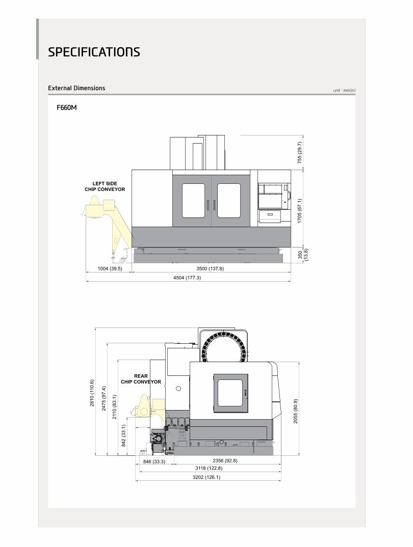
unit : mm(in)External Dimensions
F660M
1085 (42.7)
846 (33.3)
1036 (40.8)
755
(29.
7)
548
(21.
6)
LEFT SIDECHIP CONVEYOR
LEFT SIDECHIP CONVEYOR
REARCHIP CONVEYOR
REARCHIP CONVEYOR
1950
(76.
8)
2450 (96.5) 90 (3.5)315(12.4)1167 (45.9) 2540 (100)
884
(34.
8)
1860 (73.2) 34 (1.3)2979 (117.3)
1163
(45.
8)
2287
(90)
2498
(98.
3)
2833
(111
.5)
1950
(76.
8)60 (2.4
)
618(24.3)
LEFT SIDECHIP CONVEYOR
REARCHIP CONVEYOR
2356 (92.8)
3202 (126.1)
3118 (122.8)
842
(33.
1)
2110
(83.
1)
2475
(97.
4)
2810
(110
.6)
3500 (137.8)
4504 (177.3)
350
(13.
8)17
05 (6
7.1)
2055
(80.
9)
1004 (39.5)
1900
(74.
8)20
5(8
.1)
815
(32.
1)
2800
(110
.2)
2573
(101
.3)
523
(20.
6)
340
(13.
4)15
60 (6
1.4)
1197
(47.
1)19
00 (7
4.8)
378
(14.
9)
2800 (110.2)1087 (42.8)
3887 (153)
2057 (81)
2670 (105.1)
613(24.1)
SPECIFICATIONS
unit : mm(in)Table Dimensions
F510M
F660M
24+
25
F5
10M
/660
MVe
rtic
al M
achi
ning
Cen
ter
HYU
ND
AI W
IAM
ACH
INE
TOO
L
SPECIFICATIONS
unit : mmTool Shank
Ø63
65.4
6
27
2
Ø44
.45
35
29
Ø15
60°
45°
16.6
22.6
16.1
7/24
M16
Ø10
10 1
Ø4Ø3
Ø5
11.53
P5
BT40/BBT40, BIG PLUS
Ø63
18
60°
2026.5
16
20
26.5
12.54
18 Ø10
6.3 26
Ø48.01
0
HSK A-63
60°
CAT-40
Ø63.
5 (2.
5)
Ø3 (0
.118
)
Ø5 (0
.097
)
2. R0.4
11.5 (0.453)
3 (0.118)1BP5
15 (0
.59)
25(0.984)
25(0.984)
16.3
83(0.
645)
68.25 (2.687) 32.15 (1.266)
5/8″-11
Ø44.
5 (1.
75)
Ø63
65.4
6
27
2
Ø44
.45
35
29
Ø15
60°
45°
16.6
22.6
16.1
7/24
M16
Ø10
10 1
Ø4Ø3
Ø5
11.53
P5
BT40/BBT40, BIG PLUSØ6
3
18
60°
2026.5
16
20
26.5
12.54
18 Ø10
6.3 26
Ø48.01
0
HSK A-63
60°
CAT-40
Ø63.
5 (2.
5)
Ø3 (0
.118
)
Ø5 (0
.097
)
2. R0.4
11.5 (0.453)
3 (0.118)1BP5
15 (0
.59)
25(0.984)
25(0.984)
16.3
83(0.
645)
68.25 (2.687) 32.15 (1.266)
5/8″-11
Ø44.
5 (1.
75)
SPECIFICATIONS
Specifications are subject to change for improvement without notice.
❖ Standard Roller Guide included when selecting the Mold Package
ITEM F510M F660M
1,200×500(47.2″×19.7″) 1,600×650(63″×25.6″)
800(1,764) 1,300(2,866)
- -
- -
- -
BIG PLUS #40
15,000 [15,000]
25/22(33.5/29.5)[26/26(34.8/34.8)]
167/95[113/75]
BUILT-IN [BUILT-IN]
1,060/510/635(41.7″/20.1″/25″) 1,400/660/635(55.1″/26″/25″)
150~785(5.9″~30.9″)
615(24.2″)
36/36/30
15
LM GUIDE [RoLLER GUIDE]
24[30]
BBT40[CAT40][HSK-A63]
Ø90/Ø150(3.5″/5.9″)
300(11.8″)
8(17.6)
RANDoM
1.5
3.8 3.9
350(92.5)
2(0.5)
11(2.9)
110(29.1)
26 28
OVER35 OVER50
220/60(200/50)
2,910×2,690(114.6″×105.9″) 3,500×2,560(137.8″×100.8″)
2,815(110.8″) 2,800(110.2″)
7,700(16,976) 9,500(20,944)
FANUC31i-A[HYUDAIWIAFANUCiSeries][SIEMENS 828D]
Specifications [ ] : Option
26+
27
F5
10M
/660
MVe
rtic
al M
achi
ning
Cen
ter
HYU
ND
AI W
IAM
ACH
INE
TOO
L
SPECIFICATIONS
Table Size
Maximum Load Capacity
Table Change Time
Change Method
Table Driving Method
Spindle Taper
Spindle RPM
Spindle Power Output (Max./Cont.)
Spindle Torque (Max./Cont.)
Spindle Driving Method
Travel (X/Y/Z)
Distance from Table Surface to Sp
Distance from Column to SP. center
Rapid Feed Rate (X/Y/Z)
Cutting Feed Rate (X/Y/Z)
Slide Type
Number of Tools
Tool Shank
Max. Tool Dia.(W.T / W.O)
Max. Tool Length
Max. Tool Weight
Tool Selection Method
Tool Change Time T-T
C-C
Coolant Tank
Lubricating Tank
Hydraulic Tank
Air Consumption (0.5MPa)
Electric Power Supply
Thickness of Power Cable
Voltage
Floor Space (L×W)
Height
Weight
Controller
TAblE
FEED
TANkCApACITY
SpINDlE
ATC
MACHINE
NC
pOWErSUpplY
mm(in)
kg(lb)
sec
-
-
-
r/min
kW(HP)
N.m
-
mm(in)
mm(in)
mm(in)
m/min
m/min
-
EA
-
mm(in)
mm(in)
kg(lb)
-
sec
sec
ℓ(gel)
ℓ(gel)
ℓ(gel)
ℓ/min(gel)
KVA
Sq
V/Hz
mm(in)
mm(in)
kg(lb)
-
FANUC 31i-AAxis control / Display unitControlled axisSimultaneous controllable axis
Least input increment
Least command increment
Inch / Metric conversionInterlockMachine lockEmergency stopStored stroke check 1Follow-upServo offBacklash compensationPosition switchStored pitch error compensationLCD/MDIOperationAutomatic operation (memory)MDI operationDNC operationProgram restartWrong operation preventionBuffer registerProgram check functionSingle blockFeed functionsManual jog feedManual handle feed-rateFeed commandFeedrate overrideJog feedRapid traverse overrideOverride cancelRapid traverse bell-shaped acceleration/decelerationprogram input & Interpolation functionsAI contour control(AICC) Label SkipControl in/outNano InterpolationExact stop mode/Exact stopDwellHelical interpolationThreading/synchronous feedManual reference point returnReference point returnReference point return check2nd, 3rd, 4th Reference point returnProgram stop/endTape codeOptional block skipMax. programmable dimensionsProgram numberAbsolute/incremental commandDecimal point inputPlane selectionWork coordinate presetAdditional work coordinate systemManual absoluteProgrammable data inputSub program callCustom macroCircular interpolationCanned cycleOptional chamfering/corner RSkip functionAutomatic coordinate system settingCoordinate system rotationProgrammable mirror image
4 axis (X, Y, Z, B) 3 axis (Max. 4 axis)X, Y, Z axis : 0.001mm (0.0001″)B axis : 0.001degX, Y, Z axis : 0.001mm (0.0001″)B axis : 0.001degG20 / G21Each axis / All axisAll axis
Over-travel
+/- 0~9999 pulse (rapid traverse & cutting feed)
10.4″ color LCD
Need DNC Program
Dry run, program check
Rapid, Jog, handlex1, x10, x100F code feedrate direct command0~200% (10% Unit)0~5,000mm/min (197ipm)F1, F25%, F50%, F100%
40 Block
Positioning/Linear/Circular (G00/G01/G02/G03)G61 / G09G04, 0~9999.9999 sec
G33
G28G27G30M00, M01 / M02, M30EIA / ISO Automatic recognition1 ea+/- 9999.9999” (+/- 8 digits)O4 / N8G90 / G91
G17, G18, G19G52~G59G54.1 P1~P48 (48 pair)“On” fixedG1010 Step
G02, G03G73, G74, G76, G80 ~ G89
G31
G68, G69G50.1, G51.1
Sub / Spindle functionsMiscellaneous functionMiscellaneous function lockSpindle speed commandSpindle speed overrideSpindle orientationRigid tappingTool functions / Tool compensationTool functionCutter compensation CTool length measurementTool length compensationTool offset pairsTool life managementData input / Output & Editing functionsReader/Puncher interfaceMemory card input/outputEmbeded EthernetPart program storage lengthRegistered programsMemory lockBack ground editingExtended part program editingExtenal messageSetting, display, diagnosisSelf-diagnosis functionHistory displayHelp functionRun hour/Parts count displayActual cutting feedrate displayGraphic displayOperation monitor screenSpindle/Servo setting screenMulti-language displayLCD Screen SaveAuto Data Backup
OptionSub Axis ControlWork coordinate CommandWork coordinate InterpolationHelical interpolationSingle direction positioningExtenal data inputFAST ethernetAdditional work coordinate systemScalingFS 15 Tape fornatTool offset numberPart program storage lengthHigh Speed Skip FunctionData serverAI contour control(AICC)
AI contour control(AICC) 1
AI contour control(AICC) 2
Manual Guide iOptional BlockskipHandle interupt3 axis MPGprogram storage lengthProtection of data at 8 levelsAdditional custom micro change
Figures in inch are converted from metric values.Design and specifications subject to change without notice.
M4 digit
S5 digits, binary output50% ~ 120% (10% Unit)
Max. T8 digitsG40~G42Z axis INPUT CG43, G44, G4999 pair
RS232C
100Mbps320m (128Kbyte)1000 ea
Copy, move, change of NC program
Alarm & operator message
Selection of 5 optional languageScreen saver
G15, G16G12.1, G13.1G07.1G60Tool offset/message/machine zero point shift100 Mbps300 pair
200 pairMax. 1000 ea
1GB200 Block/Select the machining conditions600 Block/Select the machining conditionsData Server/Automatic shut-off device1000 Block/Select the machining conditionsData Server/Automatic shut-off deviceinteractive program9 ea (Application can be limited)
640m (256Kbyte) / 5120m (2Mbyte)
#100 ~ #199, #500 ~ #999
CONTROLLER
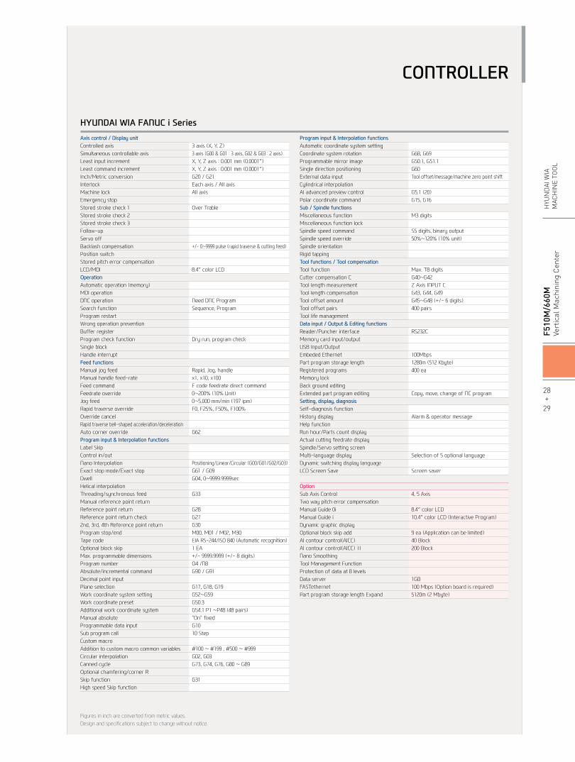
HYUNDAI WIA FANUC i SeriesAxis control / Display unitControlled axisSimultaneous controllable axisLeast input incrementLeast command incrementInch/Metric conversionInterlockMachine lockEmergency stopStored stroke check 1Stored stroke check 2Stored stroke check 3Follow-upServo offBacklash compensationPosition switchStored pitch error compensationLCD/MDIOperationAutomatic operation (memory)MDI operationDNC operationSearch functionProgram restartWrong operation preventionBuffer registerProgram check functionSingle blockHandle interruptFeed functionsManual jog feedManual handle feed-rateFeed commandFeedrate overrideJog feedRapid traverse overrideOverride cancelRapid traverse bell-shaped acceleration/decelerationAuto corner overrideprogram input & Interpolation functionsLabel SkipControl in/outNano InterpolationExact stop mode/Exact stopDwellHelical interpolationThreading/synchronous feedManual reference point returnReference point returnReference point return check2nd, 3rd, 4th Reference point returnProgram stop/endTape codeOptional block skipMax. programmable dimensionsProgram numberAbsolute/incremental commandDecimal point inputPlane selectionWork coordinate system settingWork coordinate presetAdditional work coordinate systemManual absoluteProgrammable data inputSub program callCustom macroAddition to custom macro common variablesCircular interpolationCanned cycleOptional chamfering/corner RSkip functionHigh speed Skip function
3 axis (X, Y, Z)3 axis (G00 & G01 : 3 axis, G02 & G03 : 2 axis)X, Y, Z axis : 0.001 mm (0.0001″)X, Y, Z axis : 0.001 mm (0.0001″)G20 / G21Each axis / All axisAll axis
Over Trable
+/- 0~9999 pulse (rapid traverse & cutting feed)
8.4″ color LCD
Need DNC Program Sequence, Program
Dry run, program check
Rapid, Jog, handlex1, x10, x100F code feedrate direct command0~200% (10% Unit)0~5,000 mm/min (197 ipm)F0, F25%, F50%, F100%
G62
Positioning/Linear/Circular (G00/G01/G02/G03)G61 / G09G04, 0~9999.9999sec
G33
G28G27G30M00, M01 / M02, M30EIA RS-244/ISO 840 (Automatic recognition)1 EA+/- 9999.9999 (+/- 8 digits)O4 /N8G90 / G91
G17, G18, G19G52~G59G50.3G54.1 P1 ~P48 (48 pairs)"On" fixedG1010 Step
#100 ~ #199 , #500 ~ #999G02, G03G73, G74, G76, G80 ~ G89
G31
program input & Interpolation functions Automatic coordinate system settingCoordinate system rotationProgrammable mirror imageSingle direction positioningExternal data inputCylindrical interpolationAI advanced preview controlPolar coordinate commandSub / Spindle functionsMiscellaneous functionMiscellaneous function lockSpindle speed commandSpindle speed overrideSpindle orientationRigid tappingTool functions / Tool compensationTool functionCutter compensation CTool length measurementTool length compensationTool offset amountTool offset pairsTool life managementData input / Output & Editing functionsReader/Puncher interfaceMemory card input/outputUSB Input/OutputEmbeded EthernetPart program storage lengthRegistered programsMemory lockBack ground editingExtended part program editingSetting, display, diagnosisSelf-diagnosis functionHistory displayHelp functionRun hour/Parts count displayActual cutting feedrate displaySpindle/Servo setting screenMulti-language displayDynamic switching display languageLCD Screen Save
OptionSub Axis ControlTwo way pitch error compensationManual Guide 0iManual Guide iDynamic graphic displayOptional block skip addAI contour control(AICC) AI contour control(AICC) ⅡNano SmoothingTool Management FunctionProtection of data at 8 levelsData serverFASTethernetPart program storage length Expand
Figures in inch are converted from metric values.Design and specifications subject to change without notice.
G68, G69G50.1, G51.1G60Tool offset/message/machine zero point shift
G5.1 (20)G15, G16
M3 digits
S5 digits, binary output50%~120% (10% unit)
Max. T8 digitsG40~G42Z Axis INPUT CG43, G44, G49G45~G48 (+/- 6 digits)400 pairs
RS232C
100Mbps1280m (512 Kbyte)400 ea
Copy, move, change of NC program
Alarm & operator message
Selection of 5 optional language
Screen saver
4, 5 Axis
8.4″ color LCD10.4″ color LCD (Interactive Program)
9 ea (Application can be limited)40 Block200 Block
1GB100 Mbps (Option board is required)5120m (2 Mbyte)
CONTROLLER
28+
29
F5
10M
/660
MVe
rtic
al M
achi
ning
Cen
ter
HYU
ND
AI W
IAM
ACH
INE
TOO
L
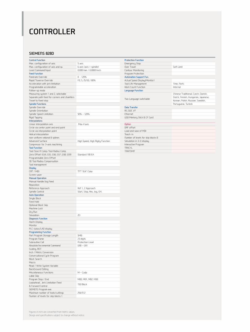
SIEMENS 828DControl FunctionMax. configuration of axisMax. configuration of axis and sp.Least Command/inputFeed FunctionFeedrate OverrideRapid Traverse OverrideAcceleration with jerk limitationProgrammable accelerationFollow-up modeMeasuring system 1 and 2, selectableSeparate path feed for corners and chamfersTravel to fixed stopSpindle FunctionsSpindle OverrideSpindle OrientationSpindle Speed LimitationRigid TappingInterpolationsLinear interpolation axisCircle via center point and end point Circle via interpolation pointHelical interpolationnon-uniform rational B splinesAdvanced SurfaceCompressor for 3-axis machiningTool FunctionTool Nose R Comp./Tool Radius Comp.Zero Offset (G54, G55, G56, G57 ,G58, G59)Programmable Zero Offset3D Tool Radius CompensationTool managementDisplayCRT / MDIScreen saverManual OperationManual Handle/Jog FeedRepositionReference ApproachSpindle ControlAuto OperationSingle BlockFeed HoldOptional Block SkipMachine LockDry RunSimulationDiagnosis FunctionAlarm DisplayMonitorPLC status/LAD displayprogramming FunctionPart Program Storage LengthProgram NameSubroutine CallAbsolute/incremental CommandScaling, ROTInch / Metric ConversionConversational Cycle ProgramBlock SearchMacroRead / Write System VariableBackGround EditingMiscellaneous FunctionsLable SkipProgram Stop / EndLookahead , Jerk Limitation Feed & Forward ControlSIEMENS Program exe.Maximum number of tools/cuttingsNumber of levels for skip blocks 1
5 axis6 axis (axis + spindle)0.0001mm / 0.00001inch
0 - 120%F0, 5, 25/50, 100%
50% - 120% Max 4 axis
High Speed, High Rigity Function
Standard 100 EA
TFT 10.4˝ Color
Ref 1, 2 ApproachStart, Stop, Rev, Jog, Ort.
2D
5MB23 digitsProtection LevelG90 - G91
M - Code M00, M01, M02, M30
150 Block
256/512
protection FunctionEmergency StopOver TravelContour MonitoringProgram ProtectionAutomation Support Fun.Actual Speed Display(Monitor)Tool Life ManagementWork Count Functionlanguage Function
Two Language switchable
Data TransferRS 232C I/FEthernetUSB Memory Stick & CF Card
OptionDRF offsetLoad and save of MDITeach-inNumber of levels for skip blocks 8 Simulation in 3-D displayInteractive ProgramTRACYLTRANSMIT
Figures in inch are converted from metric values.Design and specifications subject to change without notice.
Soft Limit
Time, PartsInternal
Chinese Traditional, Czech, Danish, Dutch, Finnish, Hungarian, Japanese, Korean, Polish, Russian, Swedish, Portuguese, Turkish
CONTROLLER
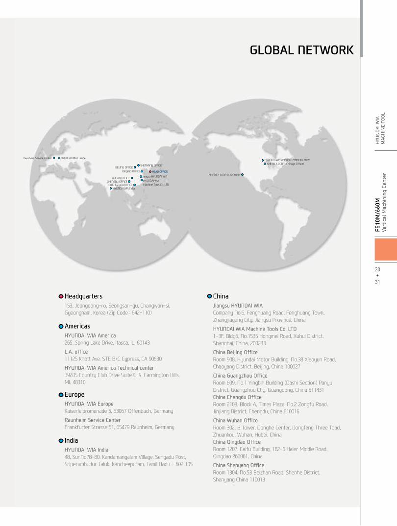
AMERICA CORP. (Chicago Office)HYUNDAI WIA America Technical Center
AMERICA CORP. (L.A Office)
BEIJING OFFICESHENYANG OFFICE
Qingdao OFFICE
Jiangsu HYUNDAI WIAHYUNDAI WIAMachine Tools Co. LTD
HEAD OFFICE
GUANGZHOU OFFICE
WUHAN OFFICECHENGDU OFFICE
HYUNDAI WIA India
HYUNDAI WIA EuropeRaunheim Service Center
GLOBAL NETWORK
AmericasHYUNDAI WIA America265, Spring Lake Drive, Itasca, IL, 60143
L.A. office11125 Knott Ave. STE B/C Cypress, CA 90630
HYUNDAI WIA America Technical center39205 Country Club Drive Suite C-9, Farmington Hills, MI, 48310
EuropeHYUNDAI WIA EuropeKaiserleipromenade 5, 63067 Offenbach, Germany
Raunheim Service CenterFrankfurter Strasse 51, 65479 Raunheim, Germany
IndiaHYUNDAI WIA India48, Sur.No78-80. Kandamangalam Village, Sengadu Post, Sriperumbudur Taluk, Kancheepuram, Tamil Nadu - 602 105
Headquarters153, Jeongdong-ro, Seongsan-gu, Changwon-si, Gyeongnam, Korea (Zip Code : 642-110)
ChinaJiangsu HYUNDAI WIACompany No.6, Fenghuang Road, Fenghuang Town,Zhangjiagang City, Jiangsu Province, China
HYUNDAI WIA Machine Tools Co. LTD1-3F, Bldg6, No.1535 Hongmei Road, Xuhui District,Shanghai, China, 200233
China Beijing OfficeRoom 908, Hyundai Motor Building, No.38 Xiaoyun Road, Chaoyang District, Beijing, China 100027
China Guangzhou OfficeRoom 609, No.1 Yingbin Building (Dashi Section) Panyu District, Guangzhou Ctiy, Guangdong, China 511431China Chengdu OfficeRoom 2103, Block A, Times Plaza, No.2 Zongfu Road, Jinjiang District, Chengdu, China 610016
China Wuhan Office Room 302, B Tower, Donghe Center, Dongfeng Three Toad, Zhuankou, Wuhan, Hubei, ChinaChina Qingdao OfficeRoom 1207, Caifu Building, 182-6 Haier Middle Road, Qingdao 266061, China
China Shenyang OfficeRoom 1304, No.53 Beizhan Road, Shenhe District,Shenyang China 110013
30+
31
F5
10M
/660
MVe
rtic
al M
achi
ning
Cen
ter
HYU
ND
AI W
IAM
ACH
INE
TOO
L