Embed Size (px)
Citation preview
Epoxy Prepreg Processing
23 November 2018 Page 1 of 15
Product Processing Guide
Key Points Summary 1 Description Gurit prepregs consist of a pre-impregnated fibre or fabric that can be laid up, consolidated and cured at temperatures above 70°C. This guide provides generic information for the processing of Gurit Epoxy Prepregs 2 Storage
• Long term –Frozen @ – 18°C ideally, at least below -5°C • Short term 4-8 weeks - De-frosted at 20°C dependent on system • Support rolls by the tube on A frame, do not allow rolls to lie flat for long periods
3 Handling • Health & Safety- protect skin from resin contact • Defrosting – ensure fully defrosted prior to removing any wrapping materials
4 Workshop • Temperature 15-20°C • Humidity <70% RH
5 Tooling • Must be capable of withstanding cure temperature under vacuum. • 100% Vacuum tight – tested prior to use
6 Surfacing Methods • Choose method ensuring appropriate option observe over coating window if
appropriate
7 Product Application • Choose resin content product as appropriate • For prepreg, best laminate quality will be achieved at lower lay-up temperatures • Lay-up neatly without bridging • Observe overlaps carefully • Follow strict de-bulking procedure to consolidate and improve laminate quality. • Use correct vacuum consumables for correct resin flow and cure temperature
8 Curing
• 95% Vacuum level, 5%/10min drop test • Ensure even heating rate and correct dwell/cure temperature and time • Careful de-moulding once cooled below 50°C
9 Records • Careful QC record keeping of material and process parameters
23 November 2018 23 November 2018 Page 2 of 15
1. Description Gurit prepreg consists of a pre-impregnated fibre or fabric that can be laid up, consolidated and finally cured at temperatures above 70°C depending on the resin system. Gurit manufactures a large range of prepreg products for many different end uses. This guide provides generic information for the processing of Gurit Epoxy Prepregs with emphasis on the most popularly used SE 84LV, SE 70 and WE 91.
2. Storage
2.1 Long Term Prepreg will remain chemically within shelf life for up to 18 months at -18 °C. When not being used prepreg should be stored at -5°C or below to maximize shelf life. In frozen storage the Prepreg should be tightly sealed in its plastic sleeve and in the original box or stillage.
2.2 Short Term Once defrosted (see 3.2 below) the material will start to age more quickly, the data sheet for the individual product will give room temperature storage life (outlife). The material should be supported by the cardboard tube to prevent weight bearing on the rolled material. An ‘A Frame’ is the best option. Standing rolls on end will allow ‘telescoping’ of the product and should be avoided if possible. Unused product should be re-wrapped in plastic and returned to frozen storage. A record of time spent unfrozen should be kept for each roll. When making a large structure it is common to take days or even weeks to construct the laminate before curing. It is critical that the outlife and temperature of the chosen product is adhered to. Curing laminate which has exceeded the outlife may result in reduced flow of the matrix resin resulting in a reduction of laminate quality.
3. Handling
3.1 Health and Safety Safety Data Sheets (SDS) are available on request from Gurit Technical Support, which detail all applicable risk phrases. Gurit recommends these are consulted and COSHH assessments carried out before using any prepreg products. Protective clothing should always be worn when handling Prepreg products. In general skin contact should be avoided when handling uncured or partially cured prepreg, by wearing suitable Nitrile gloves and change as often as required. Large prepreg rolls can be very heavy- the weight should be checked before handling, and manual handling aids used if required.
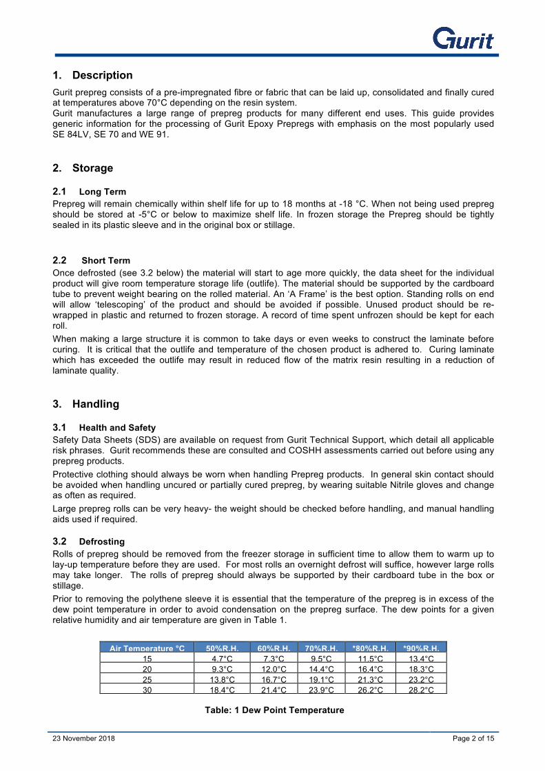
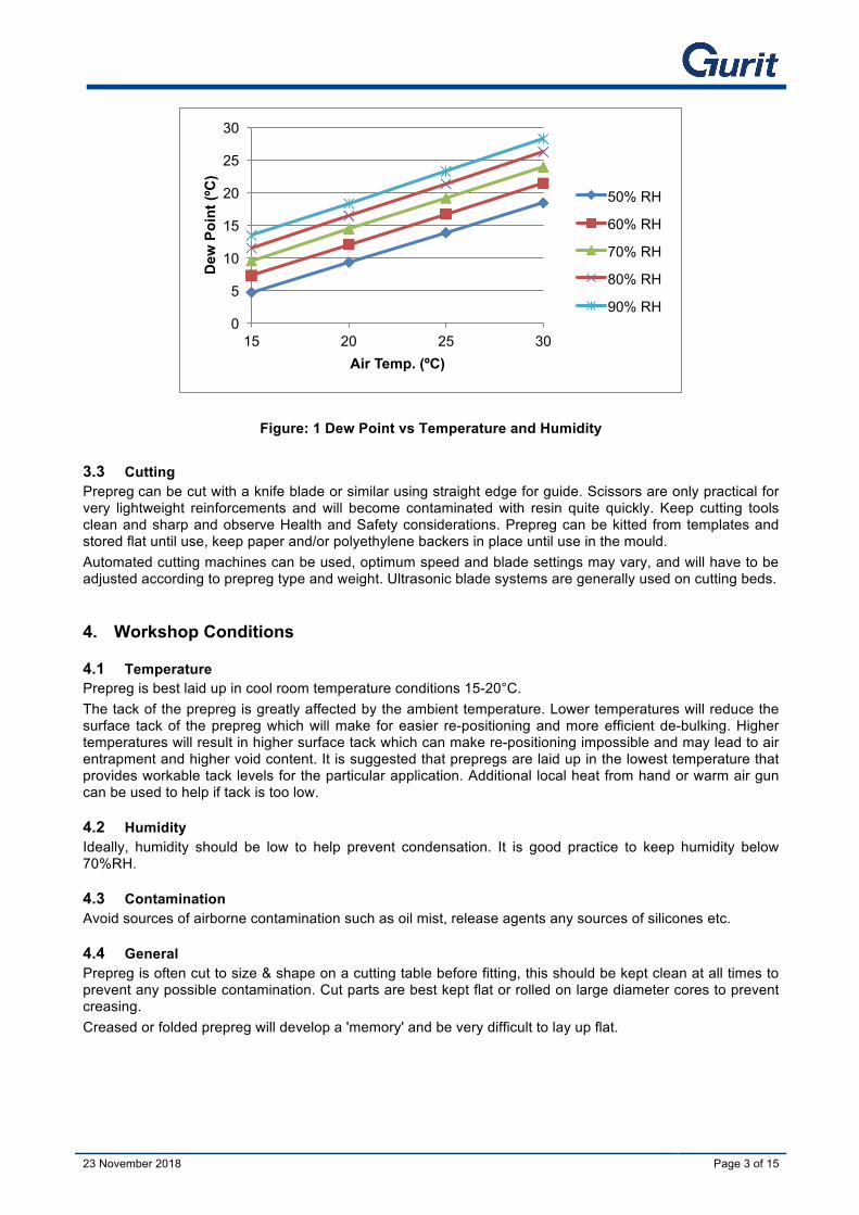
3.2 Defrosting Rolls of prepreg should be removed from the freezer storage in sufficient time to allow them to warm up to lay-up temperature before they are used. For most rolls an overnight defrost will suffice, however large rolls may take longer. The rolls of prepreg should always be supported by their cardboard tube in the box or stillage. Prior to removing the polythene sleeve it is essential that the temperature of the prepreg is in excess of the dew point temperature in order to avoid condensation on the prepreg surface. The dew points for a given relative humidity and air temperature are given in Table 1.
Air Temperature °C 50%R.H. 60%R.H. 70%R.H. *80%R.H. *90%R.H. 15 4.7°C 7.3°C 9.5°C 11.5°C 13.4°C 20 9.3°C 12.0°C 14.4°C 16.4°C 18.3°C 25 13.8°C 16.7°C 19.1°C 21.3°C 23.2°C 30 18.4°C 21.4°C 23.9°C 26.2°C 28.2°C
Table: 1 Dew Point Temperature
23 November 2018 23 November 2018 Page 3 of 15
Figure: 1 Dew Point vs Temperature and Humidity
3.3 Cutting Prepreg can be cut with a knife blade or similar using straight edge for guide. Scissors are only practical for very lightweight reinforcements and will become contaminated with resin quite quickly. Keep cutting tools clean and sharp and observe Health and Safety considerations. Prepreg can be kitted from templates and stored flat until use, keep paper and/or polyethylene backers in place until use in the mould. Automated cutting machines can be used, optimum speed and blade settings may vary, and will have to be adjusted according to prepreg type and weight. Ultrasonic blade systems are generally used on cutting beds.
4. Workshop Conditions
4.1 Temperature Prepreg is best laid up in cool room temperature conditions 15-20°C. The tack of the prepreg is greatly affected by the ambient temperature. Lower temperatures will reduce the surface tack of the prepreg which will make for easier re-positioning and more efficient de-bulking. Higher temperatures will result in higher surface tack which can make re-positioning impossible and may lead to air entrapment and higher void content. It is suggested that prepregs are laid up in the lowest temperature that provides workable tack levels for the particular application. Additional local heat from hand or warm air gun can be used to help if tack is too low.
4.2 Humidity Ideally, humidity should be low to help prevent condensation. It is good practice to keep humidity below 70%RH.
4.3 Contamination Avoid sources of airborne contamination such as oil mist, release agents any sources of silicones etc.
4.4 General Prepreg is often cut to size & shape on a cutting table before fitting, this should be kept clean at all times to prevent any possible contamination. Cut parts are best kept flat or rolled on large diameter cores to prevent creasing. Creased or folded prepreg will develop a 'memory' and be very difficult to lay up flat.
0
5
10
15
20
25
30
15 20 25 30
Dew
Poi
nt (º
C)
Air Temp. (ºC)
50% RH
60% RH
70% RH
80% RH
90% RH
23 November 2018 23 November 2018 Page 4 of 15
5. Tooling
5.1 Materials The tool should be constructed from materials that will retain their dimensional stability at the intended processing conditions. Consider cure temperature of the resin system, -1 bar pressure and the number of parts required from the tool. Considerations should also be made for the thermal properties of the tool, thermal conductivity, thermal mass, and coefficient of thermal expansion. Ideally the coefficient of thermal expansion of the tool should be matched to the coefficient of thermal expansion of the component being made e.g. carbon part = carbon tool. For some structures it will be necessary to have a significant amount of heat flow through the tool from the underside. If this is the case the tool must allow sufficient air flow over the rear face and any support structure must be designed with this in mind. Cored tools will usually have significant insulating qualities meaning that there may be a significant temperature lag at the laminate to tool interface. Bear this in mind when designing the tooling.
5.2 Structure Any joins in the mould need to be sealed and airtight as tooling leaks can be responsible for low quality or scrap parts. The design should incorporate as few joins as possible and where necessary should incorporate good sealing systems such as inbuilt rubber O rings.
5.3 Surface The surface finish will depend on the requirements of the part but needs to be non -porous and treated with a good release system. Vacuum integrity should be checked before any parts are made; surfaces may be sealed with high temperature lacquer/coating system such as Duratec. Release agents need to be capable of withstanding the intended cure temperatures, wax is generally not used with prepreg; semi-permanent products from companies such as Chemtrend, Frekote, Zyvax, are generally favoured and should be applied according to the manufacturers’ recommendations. PTFE adhesive film provides a good pinhole free release surface but as it is micro-porous, vacuum bags should be sealed to the tool outside of the PTFE film.
5.4 Tool Validation Before building parts, the mould should be vacuum tested through the intended cure cycle. This will ensure that vacuum integrity is maintained even when the mould and support frame expands at temperature. Vacuum Level must exceed an absolute minimum of 90% (approx. 900 mbar) and vacuum drop should be less than 5% over 10 minutes. During this stage a detailed map of mould temperatures should be made in order that cold or hot spots can be identified and corrected. Prepreg requires even and controlled heating in order to provide quality parts and uniform curing
6. Surfacing Methods
6.1 Surfacing Films Gurit produce a range of surfacing films that are designed to be placed in mould to provide good quality surface that will in turn provide a good base for a painted finish system.
Product Resin Weights
Colour Comment Minimum Cure Time / Temperature
SF70 150g Light green Toughened, Paintable 16 hrs. 70°C
SF80 150g Light green Toughened, Paintable 12 hrs. 80°C
SF80FR OBL 100g Black Opaque black fire-retardant film 12 hrs. 85°C
SF96 300g Dark Grey Stable, sandable, Ideal for post painting. 12 hrs. 85°C
SF95 VH 300g. Dark Grey Abrasion resistant 12 hrs. 85°C
Table: 2 Surface Films
Note* the surfacing films contain two 70g/m² fine weave glass carrier scrims. The total weight of the film is therefore 140g plus the resin weight.

23 November 2018 23 November 2018 Page 5 of 15
6.2 Liquid Process Coat There are two process coat options form Gurit, both are designed to provide a pinhole free easy to sand surface for subsequent painting operations. CR3400 is a highly filled and opaque two component ‘gelcoat’ that is applied into the mould by roller or brush, Prepreg Process Coat (SPX 20300) is a semi-transparent in mould coating designed for industrial applications such as wind turbine blades with machine mixing, contact Gurit Technical Support for information on this product. Neither of these products offer weather resistance and are intended as priming systems for a proprietary top coat system.
7. Prepreg Product Application Key processing points are;
1. Correct workshop temperature 2. Careful handling and storage of the materials 3. Neat and accurate layup of the material avoiding bridging and creasing 4. Diligent de-bulking regime to reduce voiding 5. Good vacuum integrity and level 6. Good and even control of heating to all parts of the mould and component
7.1 Surfacing Film The surface films are essentially lightweight breathable Single Sided SPRINT® products and have a partially impregnated fine reinforcement layer; the breathable surface provides a smooth defect free surface. The surface film is usually applied with the ‘tacky side ‘(paper side) against the tool, it is important to ensure that the backer is completely removed from ‘under’ the film as it is positioned. It is very difficult to re-position as it will distort if removed so great care is needed to position correctly. Use a wide soft brush or rubber squeegee to smooth out any air bubbles trapped underneath. Many users like to use a brief vacuum de-bulking process to ensure good mould adhesion and air removal from the surface film. This is especially useful if heavy reinforcements are to be used on vertical or over hang surfaces. Overlaps should be kept as small as possible; butt joints can be used but are difficult to ensure complete gap-free coverage. Surfacing films are optimised for Sprint, when used with prepreg they should be vacuum de-bulked onto the mould surface before commencing with the remaining laminate. Due to the lower breathability of prepreg the surface quality might be less pin-hole free than with Sprint.
Figure: 2 SF80 Surface Film Application.
23 November 2018 23 November 2018 Page 6 of 15
7.2 In Mould Processing Coats CR3400 or SPX20300 Process coat are two-component products mixed and applied direct to the mould. Please refer to the relevant data sheets for further information. It is important that back up times are respected as this will affect adhesion.
7.3 Prepreg layup
7.3.1 Workshop temperature Temperature control as mentioned above is very important to control the tack and therefore the handling. It is preferable to lay up in lower temperature <20°C as material re-positioning is easier, material distortion is easier to control and vacuum de-bulks are more effective. Lifting and handling long lengths of unrolled prepreg at higher temperatures can more easily lead to sideways shear making bumping more likely.
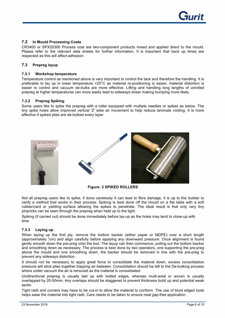
7.3.2 Prepreg Spiking Some users like to spike the prepreg with a roller equipped with multiple needles or spikes as below. The tiny spike holes allow improved vertical 'Z' wise air movement to help reduce laminate voiding. It is more effective if spiked plies are de-bulked every layer.
Figure: 3 SPIKED ROLLERS
Not all prepreg users like to spike, if done carelessly it can lead to fibre damage, it is up to the builder to verify a method that works in their process. Spiking is best done off the mould on a flat table with a soft rubber/card or yielding surface allowing the spikes to penetrate. The ideal result is that only very tiny pinpricks can be seen through the prepreg when held up to the light. Spiking (if carried out) should be done immediately before lay-up as the holes may tend to close-up with time.
7.3.3 Laying up When laying up the first ply, remove the bottom backer (either paper or MDPE) over a short length (approximately ½m) and align carefully before applying any downward pressure. Once alignment is found gently smooth down the pre-preg onto the tool. The layup can then commence, pulling out the bottom backer and smoothing down as necessary. The process is best done by two operators, one supporting the pre-preg above the mould and one smoothing down, the backer should be removed in line with the pre-preg to prevent any sideways distortion. It should not be necessary to apply great force to consolidate the material down, excess consolidation pressure will stick plies together trapping air between. Consolidation should be left to the De-bulking process where under vacuum the air is removed as the material is consolidated. Unidirectional prepreg is usually laid up with butted edges, whereas multi-axial or woven is usually overlapped by 20-50mm. Any overlaps should be staggered to prevent thickness build up and potential weak spots. Tight radii and corners may have to be cut-in to allow the material to conform. The use of blunt edged tools helps ease the material into tight radii. Care needs to be taken to ensure neat gap-free application.
23 November 2018 23 November 2018 Page 7 of 15
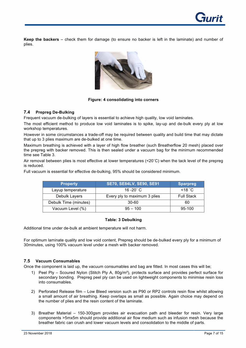
Keep the backers – check them for damage (to ensure no backer is left in the laminate) and number of plies.
Figure: 4 consolidating into corners
7.4 Prepreg De-Bulking Frequent vacuum de-bulking of layers is essential to achieve high quality, low void laminates. The most efficient method to produce low void laminates is to spike, lay-up and de-bulk every ply at low workshop temperatures. However in some circumstances a trade-off may be required between quality and build time that may dictate that up to 3 plies maximum are de-bulked at one time. Maximum breathing is achieved with a layer of high flow breather (such Breatherflow 20 mesh) placed over the prepreg with backer removed. This is then sealed under a vacuum bag for the minimum recommended time see Table 3. Air removal between plies is most effective at lower temperatures (<20˚C) when the tack level of the prepreg is reduced. Full vacuum is essential for effective de-bulking, 95% should be considered minimum.
Property SE70, SE84LV, SE90, SE91 Sparpreg Layup temperature 16 -20˚ C <18 ˚C
Debulk Layers Every ply to maximum 3 plies Full Stack Debulk Time (minutes) 30-60 60
Vacuum Level (%) 95 – 100 95-100
Table: 3 Debulking
Additional time under de-bulk at ambient temperature will not harm. For optimum laminate quality and low void content, Prepreg should be de-bulked every ply for a minimum of 30minutes, using 100% vacuum level under a mesh with backer removed.
7.5 Vacuum Consumables Once the component is laid up, the vacuum consumables and bag are fitted. In most cases this will be;
1) Peel Ply – Scoured Nylon (Stitch Ply A, 80g/m²), protects surface and provides perfect surface for secondary bonding. Prepreg peel ply can be used on lightweight components to minimise resin loss into consumables.
2) Perforated Release film – Low Bleed version such as P90 or RP2 controls resin flow whilst allowing a small amount of air breathing. Keep overlaps as small as possible. Again choice may depend on the number of plies and the resin content of the laminate.
3) Breather Material – 150-300gsm provides air evacuation path and bleeder for resin. Very large
components >5mx5m should provide additional air flow medium such as infusion mesh because the breather fabric can crush and lower vacuum levels and consolidation to the middle of parts.
23 November 2018 23 November 2018 Page 8 of 15
4) Vacuum bag – high temperature, high elongation bag is used along with high temperature sealant
tape.
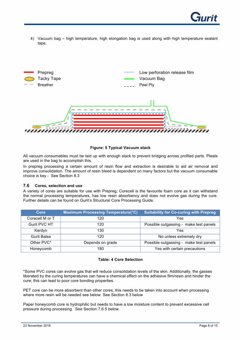
Prepreg Low perforation release film Tacky Tape Vacuum Bag
Breather Peel Ply
Figure: 5 Typical Vacuum stack
All vacuum consumables must be laid up with enough slack to prevent bridging across profiled parts. Pleats are used in the bag to accomplish this. In prepreg processing a certain amount of resin flow and extraction is desirable to aid air removal and improve consolidation. The amount of resin bleed is dependent on many factors but the vacuum consumable choice is key - See Section 8.3
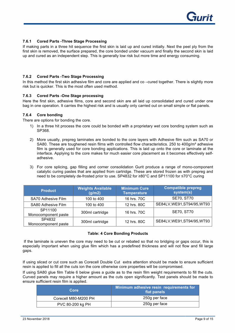
7.6 Cores, selection and use A variety of cores are suitable for use with Prepreg; Corecell is the favourite foam core as it can withstand the normal processing temperatures, has low resin absorbency and does not evolve gas during the cure. Further details can be found on Gurit’s Structural Core Processing Guide.
Core Maximum Processing Temperature(°C) Suitability for Co-curing with Prepreg Corecell M or T 120 Yes Gurit PVC HT 120 Possible outgassing - make test panels
Kerdyn 130 Yes Gurit Balsa 120 No unless extremely dry Other PVC* Depends on grade Possible outgassing - make test panels Honeycomb 180 Yes with certain precautions
Table: 4 Core Selection
*Some PVC cores can evolve gas that will reduce consolidation levels of the skin. Additionally, the gasses liberated by the curing temperatures can have a chemical effect on the adhesive film/resin and hinder the cure; this can lead to poor core bonding properties.
PET core can be more absorbent than other cores, this needs to be taken into account when processing where more resin will be needed see below. See Section 8.3 below
Paper honeycomb core is hydrophilic but needs to have a low moisture content to prevent excessive cell pressure during processing. See Section 7.6.5 below.
23 November 2018 23 November 2018 Page 9 of 15
7.6.1 Cored Parts -Three Stage Processing If making parts in a three hit sequence the first skin is laid up and cured initially. Next the peel ply from the first skin is removed, the surface prepared, the core bonded under vacuum and finally the second skin is laid up and cured as an independent step. This is generally low risk but more time and energy consuming.
7.6.2 Cored Parts -Two Stage Processing In this method the first skin adhesive film and core are applied and co –cured together. There is slightly more risk but is quicker. This is the most often used method.
7.6.3 Cored Parts -One Stage processing Here the first skin, adhesive films, core and second skin are all laid up consolidated and cured under one bag in one operation. It carries the highest risk and is usually only carried out on small simple or flat panels.
7.6.4 Core bonding There are options for bonding the core.
1) In a three hit process the core could be bonded with a proprietary wet core bonding system such as SP368.
2) More usually, prepreg laminates are bonded to the core layers with Adhesive film such as SA70 or SA80. These are toughened resin films with controlled flow characteristics. 250 to 400g/m² adhesive film is generally used for core bonding applications. This is laid up onto the core or laminate at the interface. Applying to the core makes for much easier core placement as it becomes effectively self-adhesive.
3) For core splicing, gap filling and corner consolidation Gurit produce a range of mono-component catalytic curing pastes that are applied from cartridge. These are stored frozen as with prepreg and need to be completely de-frosted prior to use. SP4832 for ≥80°C and SP11100 for ≤70°C curing
Product Weights Available (g/m2)
Minimum Cure Temperature
Compatible prepreg system(s)
SA70 Adhesive Film 100 to 400 16 hrs. 70C SE70, ST70
SA80 Adhesive Film 100 to 400 12 hrs. 80C SE84LV,WE91,ST94/95,WT93 SP11100
Monocomponent paste 300ml cartridge 16 hrs. 70C SE70, ST70
SP4832 Monocomponent paste 300ml cartridge 12 hrs. 80C SE84LV,WE91,ST94/95,WT93
Table: 4 Core Bonding Products
If the laminate is uneven the core may need to be cut or rebated so that no bridging or gaps occur, this is especially important when using glue film which has a predefined thickness and will not flow and fill large gaps. If using sliced or cut core such as Corecell Double Cut extra attention should be made to ensure sufficient resin is applied to fill all the cuts ion the core otherwise core properties will be compromised. If using SA80 glue film Table 6 below gives a guide as to the resin film weight requirements to fill the cuts. Curved panels may require a higher amount as the cuts open significantly. Test panels should be made to ensure sufficient resin film is applied.
Core Minimum adhesive resin requirements for
flat panels Corecell M80-M200 PH 250g per face
PVC 80-200 kg PH 250g per face

23 November 2018 23 November 2018 Page 10 of 15
PET 80-200 kg PH 400g per face
Corecell M80-M200 DC (knife cut) 400g per face
Table 6: Adhesive Film Requirements
7.6.5 Nomex Processing. Building with Nomex honeycomb presents an additional processing concern. The air in the cells and any moisture contained in the phenolic resin coated paper will expand when heat cycled through a typical cure. The trick is to allow air to be withdrawn by the vacuum prior to heating and to ensure that the Nomex is as dry as possible prior to layup. Nomex cored parts are usually made as a two stage or three stage process as described above, the Nomex is co-cured with the first skin using a glue film or it can be bonded as a secondary operation using glue film or a wet bond adhesive such as SP368. The second skin needs to allow the air in the cells to escape. Typically the surface of the Nomex is abraded to allow some cell to cell air movement and the inner skin laid up with a 250g glue film, normal de-bulks are used and then the entire top skin is spiked at approx. 50mm centres using a 2mm spike. These holes allow air to escape - before closing up when the prepreg resin flows and cures. There are other approaches to dealing with Nomex - For further details of processing with honeycomb materials contact Gurit Technical Support.
Figure: 6 Spiking Inner Skin to Vent Nomex.
7.6.6 Partial Cures When building a laminate in several stages it is often possible to save some energy and time by giving the initial plies a partial cure only. As long as the final stage includes a full cure cycle, the first cures can be reduced by around 50%. At this stage the laminate will not have full structural strength, but will be cured sufficiently to allow subsequent layers/cores etc. to be laid up. The part must remain in the mould until after the final full cure. System Minimum Partial Cure Minimum Full Cure SE70 8 hrs. 70°C 16 hrs. 70°C SE84LV 6 hrs. 80°C 12 hrs. 80°C WE91 5 hrs. 85°C 10hrs 85°C
Table: 5 Partial Cures
7.7 SPRINT™ Prepregs and SPRINT™ materials can and are frequently used and co-cured together to obtain optimised laminates with reduced de-bulking and easier layup. Contact Technical support for details.
7.8 Autoclave Processing All of Gurit’s epoxy prepregs are suitable for autoclave processing with pressures up to 6 bar. Laminates should be kept under vacuum for at least 1 hour before curing.
23 November 2018 23 November 2018 Page 11 of 15
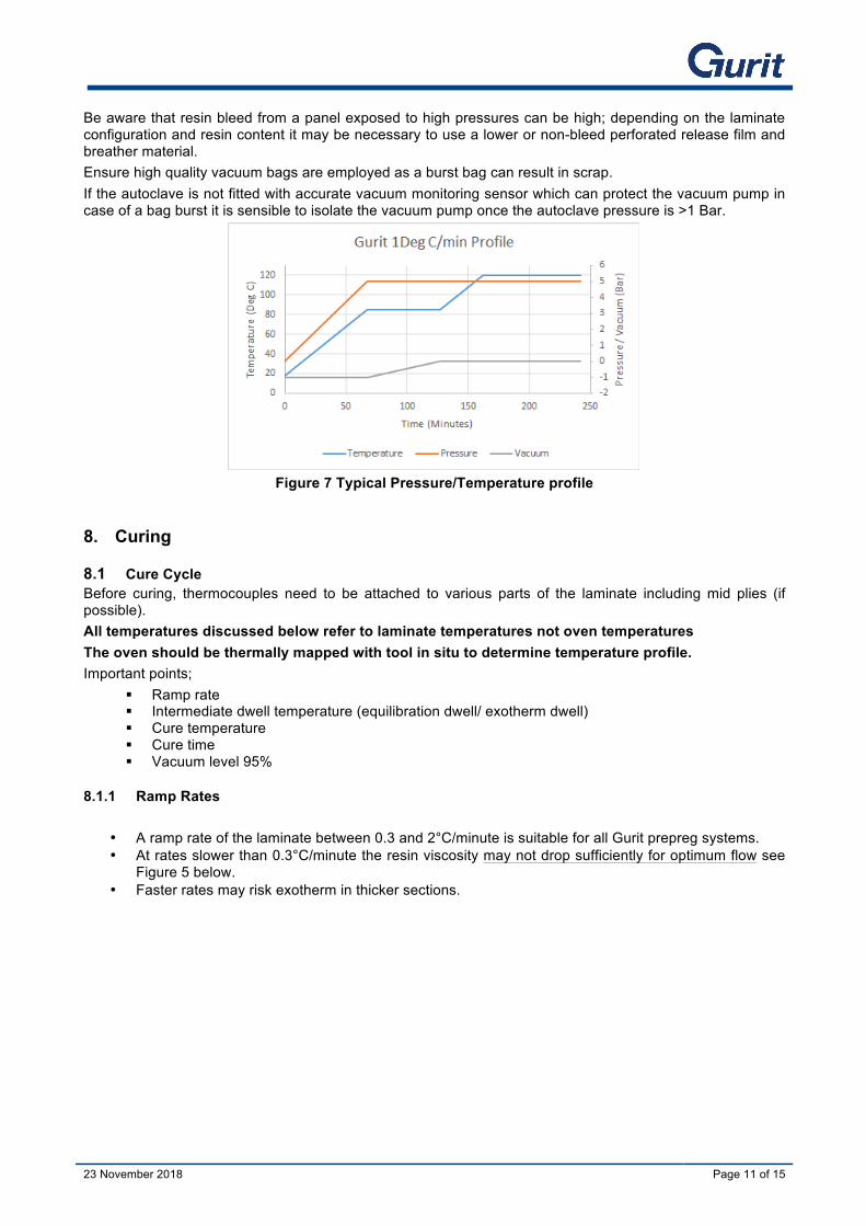
Be aware that resin bleed from a panel exposed to high pressures can be high; depending on the laminate configuration and resin content it may be necessary to use a lower or non-bleed perforated release film and breather material. Ensure high quality vacuum bags are employed as a burst bag can result in scrap. If the autoclave is not fitted with accurate vacuum monitoring sensor which can protect the vacuum pump in case of a bag burst it is sensible to isolate the vacuum pump once the autoclave pressure is >1 Bar.
Figure 7 Typical Pressure/Temperature profile
8. Curing
8.1 Cure Cycle Before curing, thermocouples need to be attached to various parts of the laminate including mid plies (if possible). All temperatures discussed below refer to laminate temperatures not oven temperatures The oven should be thermally mapped with tool in situ to determine temperature profile. Important points;
§ Ramp rate § Intermediate dwell temperature (equilibration dwell/ exotherm dwell) § Cure temperature § Cure time § Vacuum level 95%
8.1.1 Ramp Rates
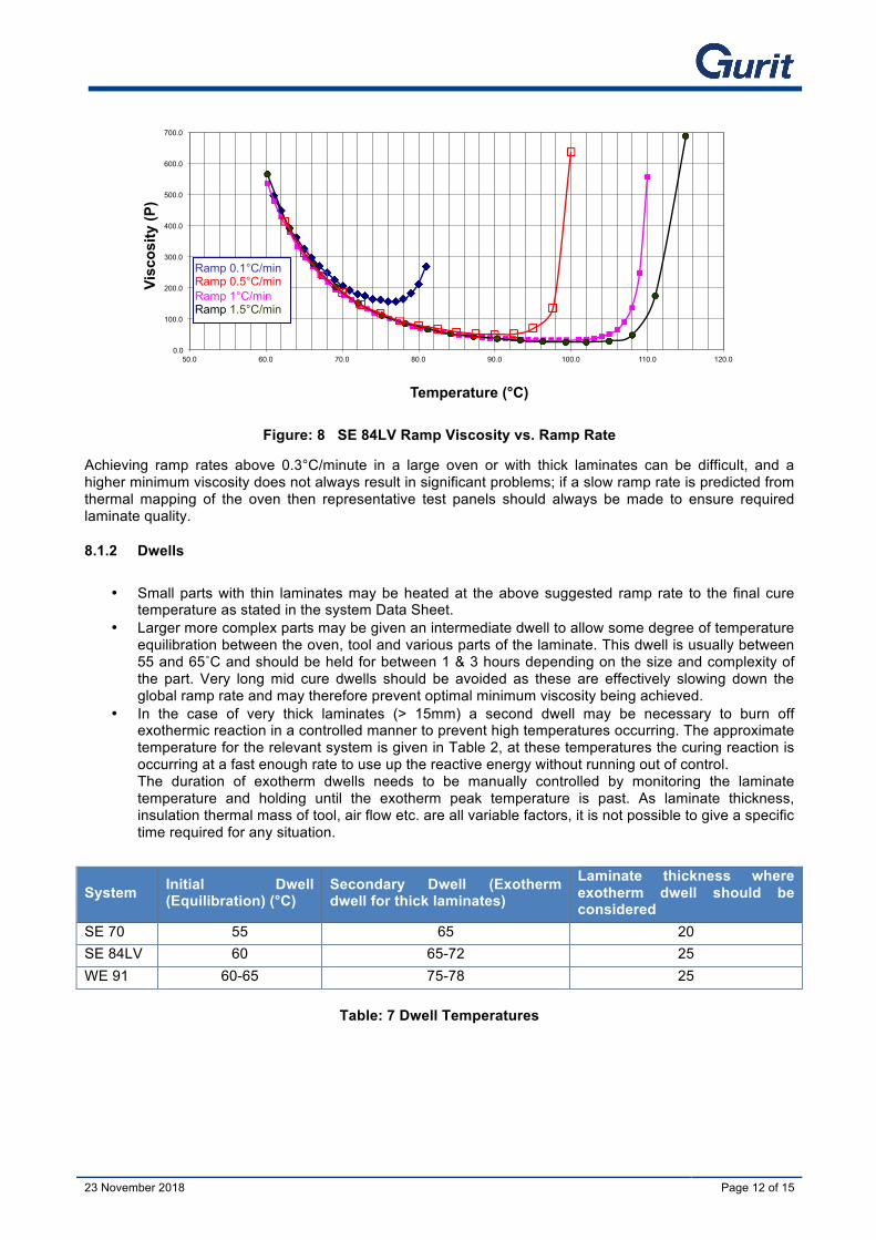
• A ramp rate of the laminate between 0.3 and 2°C/minute is suitable for all Gurit prepreg systems. • At rates slower than 0.3°C/minute the resin viscosity may not drop sufficiently for optimum flow see
Figure 5 below. • Faster rates may risk exotherm in thicker sections.
23 November 2018 23 November 2018 Page 12 of 15
Figure: 8 SE 84LV Ramp Viscosity vs. Ramp Rate
Achieving ramp rates above 0.3°C/minute in a large oven or with thick laminates can be difficult, and a higher minimum viscosity does not always result in significant problems; if a slow ramp rate is predicted from thermal mapping of the oven then representative test panels should always be made to ensure required laminate quality.
8.1.2 Dwells
• Small parts with thin laminates may be heated at the above suggested ramp rate to the final cure temperature as stated in the system Data Sheet.
• Larger more complex parts may be given an intermediate dwell to allow some degree of temperature equilibration between the oven, tool and various parts of the laminate. This dwell is usually between 55 and 65˚C and should be held for between 1 & 3 hours depending on the size and complexity of the part. Very long mid cure dwells should be avoided as these are effectively slowing down the global ramp rate and may therefore prevent optimal minimum viscosity being achieved.
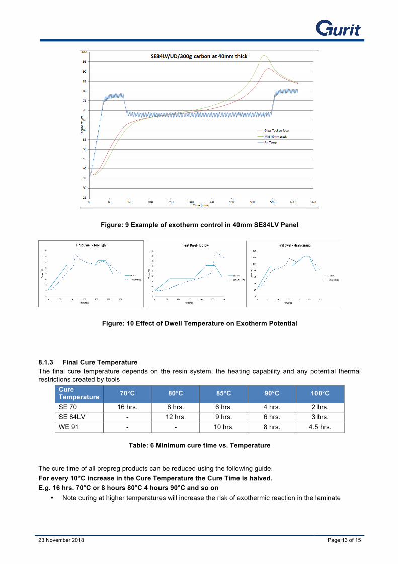
• In the case of very thick laminates (> 15mm) a second dwell may be necessary to burn off exothermic reaction in a controlled manner to prevent high temperatures occurring. The approximate temperature for the relevant system is given in Table 2, at these temperatures the curing reaction is occurring at a fast enough rate to use up the reactive energy without running out of control. The duration of exotherm dwells needs to be manually controlled by monitoring the laminate temperature and holding until the exotherm peak temperature is past. As laminate thickness, insulation thermal mass of tool, air flow etc. are all variable factors, it is not possible to give a specific time required for any situation.
System Initial Dwell (Equilibration) (°C)
Secondary Dwell (Exotherm dwell for thick laminates)
Laminate thickness where exotherm dwell should be considered
SE 70 55 65 20 SE 84LV 60 65-72 25 WE 91 60-65 75-78 25
Table: 7 Dwell Temperatures
0.0
100.0
200.0
300.0
400.0
500.0
600.0
700.0
50.0 60.0 70.0 80.0 90.0 100.0 110.0 120.0
Visc
osity
(P)
Temperature (°C)
Ramp 0.1°C/min Ramp 0.5°C/min Ramp 1°C/min Ramp 1.5°C/min
23 November 2018 23 November 2018 Page 13 of 15
Figure: 9 Example of exotherm control in 40mm SE84LV Panel
Figure: 10 Effect of Dwell Temperature on Exotherm Potential
8.1.3 Final Cure Temperature The final cure temperature depends on the resin system, the heating capability and any potential thermal restrictions created by tools
Cure Temperature 70°C 80°C 85°C 90°C 100°C
SE 70 16 hrs. 8 hrs. 6 hrs. 4 hrs. 2 hrs. SE 84LV - 12 hrs. 9 hrs. 6 hrs. 3 hrs. WE 91 - - 10 hrs. 8 hrs. 4.5 hrs.
Table: 6 Minimum cure time vs. Temperature
The cure time of all prepreg products can be reduced using the following guide. For every 10°C increase in the Cure Temperature the Cure Time is halved. E.g. 16 hrs. 70°C or 8 hours 80°C 4 hours 90°C and so on
• Note curing at higher temperatures will increase the risk of exothermic reaction in the laminate
23 November 2018 23 November 2018 Page 14 of 15
8.1.4 Full Cure & Glass Transition Temperature The minimum cure times recommended for each system will equate to >95% of the full crosslinking potential for the given temperature and will provide adequate mechanical and thermal properties. Providing additional cure by means of higher cure temperatures and/or time will only have a marginal effect on mechanical properties but can have a significant positive effect on the thermal resistance of the resin (Glass Transition Temperature (Tg)). This can be beneficial for components that are likely to be subjected to high temperature including solar radiation which can cause a phenomenon known as ‘print through’ - a cosmetic surface defect. In any event, the Tg of the resin needs to be significantly above the working temperature of the component. Table 9 demonstrates the higher Tg possible with a 100°C temperature cure.
System Minimum Cure Tg (DMA Tg1) At minimum cure
Tg (DMA Tg1) After 100˚C cure (3 hrs.)
Ultimate Tg (Theoretical maximum possible Tg)
SE70 16 hrs. 70°C 89°C 110°C 125°C SE84LV 12 hrs. 80°C 98°C 120°C 140°C WE91 10 hrs. 85°C 103°C 110°C 125°C
Table: 7 The effect of elevated cure temperature on resin Tg
Note that achieving the Ultimate Tg is often impractical requiring high post cure temperatures which may be difficult to achieve and may risk part and tool stability. – Contact Gurit Technical Support for further details.
8.2 De-moulding Parts should be allowed to cool naturally under vacuum until <50°C. Maximum cooling rate 5°C/minute
8.3 Resin Content The prepreg products are made with a fixed resin content that is slightly higher than optimal for the cured laminate; this is because a small amount of resin bleed into the vacuum consumables is beneficial in producing good quality laminates. The amount of resin that is bled out of the prepreg depends on the following factors.
• Resin System • Reinforcement type • Number of plies • Initial resin content • Cure ramp rate including dwells • Perforated release film type • Bleeder type • Vacuum pressure
Using the above recommended processing conditions and vacuum consumables a typical ‘Marine’ laminate of 2-3mm SE 84LV will bleed approximately 100-150g/m², visible as 5-10mm resin circles in the breather fabric. This equates to approximately 2% loss in resin compared to the original resin content. In thicker monolithic laminates the bleed gets proportionally less so the cured laminate will have a resin-content close to the original amount. For very thin/lightweight laminates it is possible to over-bleed, in this case it might be prudent to use a pre-impregnated peel ply or use a micro-porous release film that breathes but allows zero bleed. Contact Gurit Technical Support for more details.
9. Test Panels Gurit strongly recommends that representative test panels are always made before production parts. There are a great many variables and requirements some of which may not be covered in this guide
23 November 2018 23 November 2018 Page 15 of 15
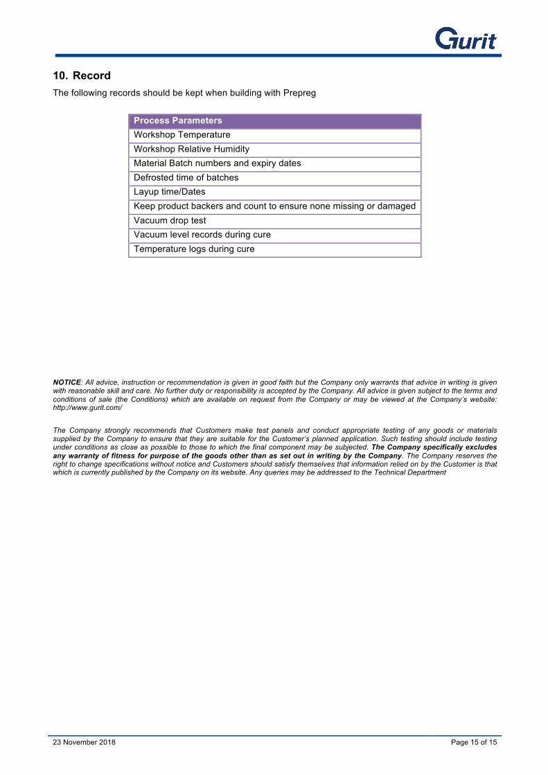
10. Record The following records should be kept when building with Prepreg
Process Parameters Workshop Temperature Workshop Relative Humidity Material Batch numbers and expiry dates Defrosted time of batches Layup time/Dates Keep product backers and count to ensure none missing or damaged Vacuum drop test Vacuum level records during cure Temperature logs during cure
NOTICE: All advice, instruction or recommendation is given in good faith but the Company only warrants that advice in writing is given with reasonable skill and care. No further duty or responsibility is accepted by the Company. All advice is given subject to the terms and conditions of sale (the Conditions) which are available on request from the Company or may be viewed at the Company’s website: http://www.gurit.com/ The Company strongly recommends that Customers make test panels and conduct appropriate testing of any goods or materials supplied by the Company to ensure that they are suitable for the Customer’s planned application. Such testing should include testing under conditions as close as possible to those to which the final component may be subjected. The Company specifically excludes any warranty of fitness for purpose of the goods other than as set out in writing by the Company. The Company reserves the right to change specifications without notice and Customers should satisfy themselves that information relied on by the Customer is that which is currently published by the Company on its website. Any queries may be addressed to the Technical Department