Embed Size (px)
Citation preview

Page 1 of 29
New Remote Intelligent Gateway and Secure Socket Layer
Validation Procedure

Page 2 of 29
REVISION HISTORY
REVCAISON NO. DATE DESCRIPTION
1.0 12/5/2001 Initial release of document
2.0 5/25/2007 Revised Security Requirements
3.3 11/4/2008 Revised Validation and Security Requirements
4.1 11/13/08 Final Edits
4.2 8/14/2013 Updated RIG Contacts
4.3 12/16/2015

Page 3 of 29
ABSTRACT
This Remote Intelligence Gateway (RIG) Validation Procedure provides vendors or device owners with
guidelines to configure and test a device for validation and use by the California Independent System
Operator Corporation (CAISO) participant providing real time telemetry. The following Procedure outlines
the responsibilities of vendors or device owners, and the CAISO staff in configuring, scheduling, and
performing testing. To request the testing and device validation vendors must fill out the validation request
form in Appendix A. Vendors and device owners should also read through the validation procedure in its
entirety and list any exceptions to this Procedure on the request form.

Page 4 of 29
TABLE OF CONTENTS
NEW REMOTE INTELLIGENT GATEWAY AND SECURE SOCKET LAYER VALIDATION PROCEDURE ... 1
REVISION HISTORY ........................................................................................................................................................ 2
ABSTRACT ........................................................................................................................................................................ 3
1 INTRODUCTION ....................................................................................................................................................... 6
1.1 TEST PREREQUISITES ......................................................................................................................................... 6 1.2 METHODOLOGY ................................................................................................................................................... 6 1.3 DISCREPANCY REPORTS .................................................................................................................................... 7 1.4 LOGISTICS ........................................................................................................................................................... 7 1.5 UNAVAILABILITY AND EXCEPTIONS ................................................................................................................... 7 1.6 RIG OWNER RESPONSIBILITY ............................................................................................................................ 7 1.7 CAISO RESPONSIBILITY ..................................................................................................................................... 7
2. SYSTEM SETUP ....................................................................................................................................................... 8
2.1 DNP / IP CONNECTION ....................................................................................................................................... 8 2.1.1 Network Agreement ..................................................................................................................................... 8 2.1.2 Block Diagram .............................................................................................................................................. 9 2.1.3 IP Addresses................................................................................................................................................. 9 2.1.4 DNP Master and Slave Address ................................................................................................................ 9 2.1.5 Test Database .............................................................................................................................................. 9
3. TEST PROCEDURE ............................................................................................................................................... 10
3.1 ANALOG INPUTS (TO CAISO) .................................................................................................................... 10 3.1.1 Heartbeat ..................................................................................................................................................... 10 3.1.2 Scaling ......................................................................................................................................................... 10 3.1.3 Deadband .................................................................................................................................................... 10 3.1.4 Summing ..................................................................................................................................................... 10 3.1.5 Scale ............................................................................................................................................................ 10 3.1.6 Data Quality / Alarming ............................................................................................................................. 10 3.1.7 RIG Heartbeat ............................................................................................................................................. 11 3.1.8 Calculations................................................................................................................................................. 11 3.1.9 Bumpless Transfer (Used for AGC control) ........................................................................................... 11
3.2 DIGITAL INPUTS ............................................................................................................................................ 12 3.2.1 Digital Input State ....................................................................................................................................... 12 3.2.2 Data Quality/ Alarming .............................................................................................................................. 12 3.2.3 Digital Communication Port Alarming ..................................................................................................... 12 3.2.4 10 Data Points ............................................................................................................................................ 12 3.2.5 Calculations................................................................................................................................................. 12 LOGIC .............................................................................................................................................................. 12
3.3 ANALOG OUTPUTS (SETPOINT) (SENT FROM CAISO EMS) ................................................................. 14 3.4 COMMUNICATION TESTING ...................................................................................................................... 14
3.4.1 Loss of Power ............................................................................................................................................. 14 3.4.2 Restart ......................................................................................................................................................... 14
3.5 CONNECTIVITY TESTING ................................................................................................................................... 15 3.5.1 Tracking ....................................................................................................................................................... 15 3.5.2 Failure Rate................................................................................................................................................. 15
REMOTE INTELLIGENT GATEWAY (RIG) SECURITY PROCEDURES ............................................................. 16
REVISION HISTORY ...................................................................................................................................................... 18

Page 5 of 29
1 PURPOSE ................................................................................................................................................................ 19
2 REQUIRED TEST CASES .................................................................................................................................... 19
2.1 CERTIFICATE RENEWAL .................................................................................................................................... 19 2.2 NEW CA ............................................................................................................................................................ 20 2.3 NEW ROOT CA ................................................................................................................................................. 21 2.4 ENCRYPTION VERIFICATION ............................................................................................................................. 22 2.5 SESSION KEY RENEWAL: EXPIRED OR REVOKED CERTIFICATES .............................................................. 23 2.6 OPTIONAL TEST CASE: CAISO CRL ........................................................................................................ 24
PROCEDURE: ................................................................................................................................................................. 24
APPENDIX A .................................................................................................................................................................... 25
RTU OWNER VALIDATION REQUEST FORM .................................................................................................................. 25
APPENDIX B .................................................................................................................................................................... 27
DISCREPANCY REPORT ................................................................................................................................................. 27 DDIISSCCRREEPPAANNCCYY RREEPPOORRTT FFOORRMM ............................................................................................................................... 28
APPENDIX C .................................................................................................................................................................... 29

Page 6 of 29
1 INTRODUCTION
The tests outlined in this Procedure will be performed with the active participation of California
Independent System Operation Corporation (CAISO) personnel, but all costs and responsibilities
(aside from providing CAISO personnel) shall be at the sole cost of the vendor or device owners.
CAISO does not assume any liability resulting from or arising out of any tests conducted pursuant to
this Procedure, unless due to the gross negligence or willful misconduct of CAISO personnel. By
requesting the tests outlined below such a vendor or device owner expressly consents to the Procedure
and agrees to the terms herein. Further, vendor and/or device owner agree to hold CAISO harmless
from all liability, except as provided herein.
1.1 TEST PREREQUISITES
The reference to ‘Owner’ in this testing and validation procedure represents the RIG Owner or
representative.
The following prerequisites are required before testing can begin:
Names and phone numbers of all test personnel (if testing remotely)
Test database spreadsheet
Signed ECN connection form if testing remotely
RTU IP address, DNS and Gateway addresses
__________________________________________________
1.2 METHODOLOGY
In order to run a successful test, it is necessary to establish the methods and general procedures which
will be followed throughout the test. It is important that these rules and procedures be agreed to, and
followed, by all parties during the test. In those cases where either methods or procedures are
violated or changed, all parties shall acknowledge the change, reach a mutually agreeable resolution
and document the results. This resolution may involve mutually agreed to changes being made to the
test procedure or resumption of the previously agreed to methods and procedures. This document
will provide the framework for the methods and procedures required to successfully validate the
Owner’s RIG solution. Related documents shall be referenced and attached to this document where
applicable.
The Owner and the CAISO will each appoint a Test Supervisor that is solely responsible for
representing their respective companies during testing. The Test Supervisors will be responsible for
approving the tests, approving any departure from the procedure, and documenting errors or
omissions. The individuals from the CAISO and the Owner conducting each series of tests will sign
off on each test procedure section.
The Test Supervisors may add or delete items from the test, redirect the test, skip sections, or review
sections at any time during the test provided such changes are agreed to by both the Owner and the
CAISO, are consistent with the terms of the Technical Standard and do not result in equipment
damage.
The tests are designed to run in the sequence given in this document except where noted. Proper
sequencing of tests is necessary because of set up procedures that may have occurred in previous
tests. However, it is recognized that circumstances often require that the sequence be interrupted.

Page 7 of 29
Such an interruption or rescheduling requires both Test Supervisors to agree, the impact of the
sequence interruption be recognized, and said interruption or rescheduling be documented.
Successful testing involves the active participation and understanding of test functions by both
parties. This will provide the CAISO with the opportunity to observe the test results. Upon successful
completion of each section, the Test Supervisors will sign off that section as complete and accepted.
When testing the RIG from a remote location the CAISO Test Supervisor will maintain the master
Validation Procedure and upon completion of the validation testing will send a copy of the signed
procedure to the Owner. This original copy shall be signed by the Owner’s Test Supervisor in the
appropriate locations and returned to the CAISO Test Supervisor.
1.3 DISCREPANCY REPORTS
There may be cases where test results are not satisfactory. Appendix B contains a Discrepancy
Report (DR) form where all unsatisfactory results are to be recorded. Discrepancy reports will also
be used to document any outstanding issues arising from the tests.
1.4 LOGISTICS
The test period will begin with an orientation meeting (or conference call) of all personnel involved in
the testing. The purpose of this meeting is to review testing procedures and to set forth what is to be
accomplished by the end of the test period. The test period will conclude with a review meeting (or
conference call). In the case where unsatisfactory test results are obtained, this meeting will be used
to mutually determine the proper course of action to obtain satisfactory results.
1.5 UNAVAILABILITY AND EXCEPTIONS
Any items or features of the Owner’s RIG that are not available or not functional at the time of the
tests must be documented on the Discrepancy Report (DR) form located in Appendix B. Exception
will be reviewed and an agreement will be reached with the Owner on how each issue is resolved.
1.6 RIG OWNER RESPONSIBILITY
The Owner is responsible for all configuration and development of the RIG device being tested.
When the Owner’s solution is ready to test the Owner will schedule the test with the CAISO Test
Supervisor.
1.7 CAISO RESPONSIBILITY
The CAISO test supervisor is responsible to ensure the RIG Owner’s request aligns with the RTU
Specification and that the specifics of the test plan will be possible within the given test environment.
The CAISO expressly reserves the right to modify, or withdraw from, the process initiated and
described herein at its sole discretion without any liability to vendor or device owners. No rights or
licenses shall be vested or granted in any party, individual or entity by virtue of its preparation to
participate in, or its participation in, such process. The CAISO expressly reserves the right to modify,
for any reason, the test procedures and any provision contained herein. No binding commitment shall
arise between the CAISO and an Owner hereunder unless the parties sign documents of agreement
that become effective in accordance with their terms. The Owners are advised that this is a CAISO
Document and hence CAISO ADR Procedures apply to any dispute arising hereunder in accordance
with Article 13 of the CAISO Tariff.

Page 8 of 29
2. SYSTEM SETUP
This section will provide the Owner the basic network and hardware requirements for the RIG to be
certified for real-time data acquisition for CAISO. A sample database, with calculations, is posted in
Appendix C for reference.
The Owner may use supplementary devices such as PLCs with their RIG to add functionality if the
RIG is unable to comply directly with CAISO technical standards. The use of supplementary devices
is acceptable, but will be noted as an exception.
2.1 DNP / IP CONNECTION
2.1.1 Network Agreement
If an Owner chooses to test remotely, then they must have the CAISO Network Agreement
submitted before connecting to the CAISO ECN and testing their device. The CAISO
Network Agreement outlines the Information Security policy, standards, and guidelines for
CAISO Connected Subscribers (CS) which is available at
http://www.caiso.com/docs/2001/09/26/2001092611012525611.pdf. Connected Subscribers
(CS) utilize the dedicated shared, high-reliability, and high bandwidth communications
network established by the CAISO, called the Energy Communications Network (ECN), for
CS to CAISO connectivity as well as CS to CS connectivity. All entities that access the ECN
are required to sign this agreement.

Page 9 of 29
2.1.2 Block Diagram
The Owner must provide a communication block diagram of the physical RIG configuration.
The Block diagram should indicate all external devices, and how they are connected to the
RIG. Each port must be labeled and identified, indicating the type of device connected. The
diagram should be submitted no later than two weeks prior to testing. A sample block
diagram is provided below
TEST DEVICE
Energy Communication
Network
TEST EMS 2TEST EMS 1
FIREWALL
DCS OR PLC
SYSTEM
DNP 3.0
TCP/IP
DNP 3.0
TCP/IP
DNP 3.0
TCP/IP
RTU
Remote I/O
Analog / Digital
PORT 1 PORT 2 PORT 3
NIC
10.120.81.1 10.120.81.2
10.58.12.3
Block Diagram Example
2.1.3 IP Addresses
IP addresses will be provided by CAISO if the RIG is tested at the CAISO test center. IP
addresses of the CAISO master will be provided by the CAISO.
2.1.4 DNP Master and Slave Address
The RIG must be configured to allow two DNP master addresses (provided by the CAISO)
and the RIG DNP slave device set to address 1.
2.1.5 Test Database
CAISO will provide a test database to the Owner in .CSV format. The Test Database will
have a minimum of 10 analog inputs, and 10 digital inputs. To be certified for AGC use, a
RIG shall be capable of accepting at least 2 analog outputs. It will be configured to the
sample database listed in Appendix C.
Page 10 of 29
3. TEST PROCEDURE
The validation test will be conducted by CAISO and the Owner. The Owner may choose to perform
validation testing remotely, if so, they must order a CAISO Energy Communication Network AT&T
circuit. Owners must provide CAISO with the IP address of the circuit. Testing can also be performed
at CAISO, where CAISO will provide the Owner with an IP address.
Owners are expected to have all setup procedures, and DNP certifications completed or provide DNP
driver exceptions one week before the testing and validations date
CAISO engineers have the responsibility to track, analyze, and amend any test procedures as they see
fit, to test the functionality and reliability of the test device.
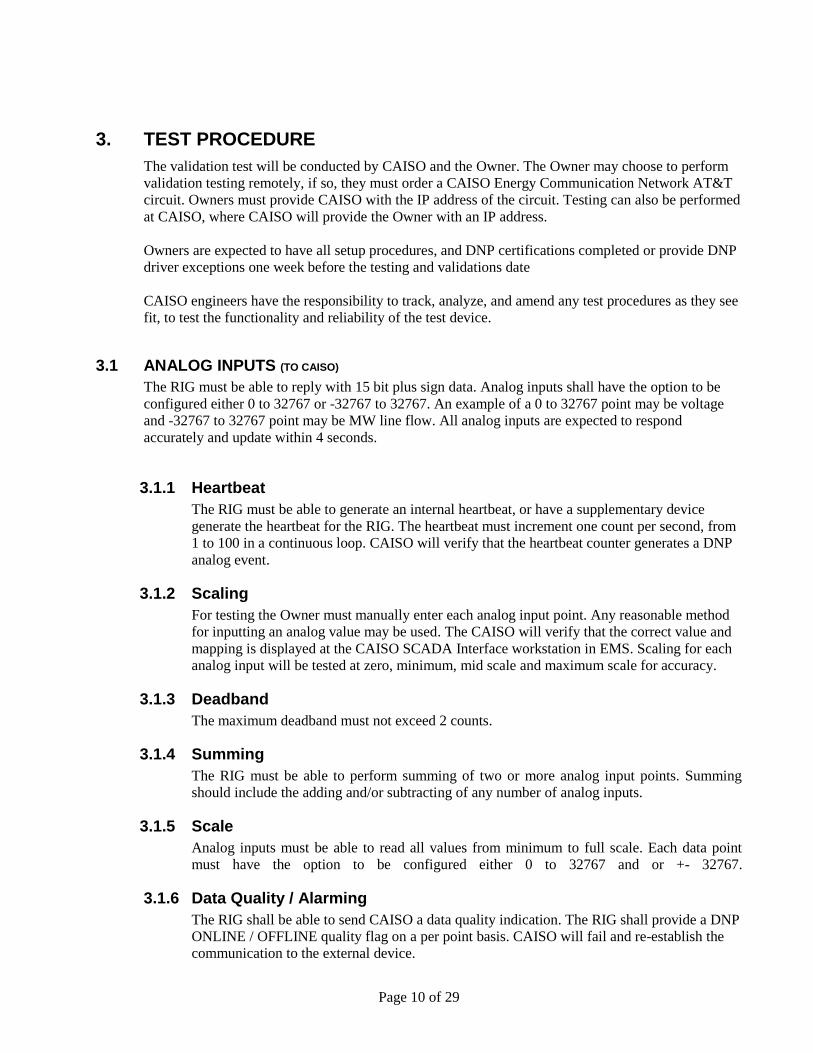
3.1 ANALOG INPUTS (TO CAISO)
The RIG must be able to reply with 15 bit plus sign data. Analog inputs shall have the option to be
configured either 0 to 32767 or -32767 to 32767. An example of a 0 to 32767 point may be voltage
and -32767 to 32767 point may be MW line flow. All analog inputs are expected to respond
accurately and update within 4 seconds.
3.1.1 Heartbeat
The RIG must be able to generate an internal heartbeat, or have a supplementary device
generate the heartbeat for the RIG. The heartbeat must increment one count per second, from
1 to 100 in a continuous loop. CAISO will verify that the heartbeat counter generates a DNP
analog event.
3.1.2 Scaling
For testing the Owner must manually enter each analog input point. Any reasonable method
for inputting an analog value may be used. The CAISO will verify that the correct value and
mapping is displayed at the CAISO SCADA Interface workstation in EMS. Scaling for each
analog input will be tested at zero, minimum, mid scale and maximum scale for accuracy.
3.1.3 Deadband
The maximum deadband must not exceed 2 counts.
3.1.4 Summing
The RIG must be able to perform summing of two or more analog input points. Summing
should include the adding and/or subtracting of any number of analog inputs.
3.1.5 Scale
Analog inputs must be able to read all values from minimum to full scale. Each data point
must have the option to be configured either 0 to 32767 and or +- 32767.
3.1.6 Data Quality / Alarming
The RIG shall be able to send CAISO a data quality indication. The RIG shall provide a DNP
ONLINE / OFFLINE quality flag on a per point basis. CAISO will fail and re-establish the
communication to the external device.

Page 11 of 29
The use of DNP ONLINE / OFFLINE quality flag is required for all analog points. When
communication is lost with any external device the analog data associated with that device
should indicate an OFFLINE status. The use of the DNP ONLINE / OFFLINE quality flag
shall be set from within the RIG.
For example:
If there are two serial communication ports ‘A’ and ‘B’ connected to the RIG device
and port ‘A’ fails, those points associated with port ‘A’ alone have their DNP data
quality flags set to OFFLINE internally to the RIG. While port ‘B’ data points DNP
remain set to ONLINE.
If external points are connected to a network LAN device and the LAN fails to
communicate only those points associated to that LAN port have their DNP quality
flags set to OFFLINE.
3.1.7 RIG Heartbeat
When communication fails between the CAISO and the RIG, CAISO will see the RIG
heartbeat stop. When communication is restored between the two systems the heartbeat in the
RIG shall continue to increment. The heartbeat in the RIG should continue to increment at all
times whether the CAISO is connected or not.
3.1.8 Calculations
All calculations indicated on the test database will be checked for accuracy and timing by
CAISO personnel.
The RIG at a minimum must be capable of performing all calculations in section 3. If the RIG
lacks functionality to perform the calculations, the use supplementary devices, such a PLC to
perform calculations is acceptable; however, exceptions will be noted.
3.1.9 Bumpless Transfer (Used for AGC control)
The RIG may have the option to set up a Bumpless transfer method for AGC control, to track
SETPOINT when generating units are off AGC control. A calculated SETPOINT will be
stored in the RIG continually updating the set point with the current MW value of the
generator. When the generator transfers to CAISO AGC control the generator should not
“bump” to a different MW output until a new CAISO MW set point is received at the RIG.
Section Complete RIG Owner______________ Date______________
CAISO_________________ Date______________
Comments:
Page 12 of 29
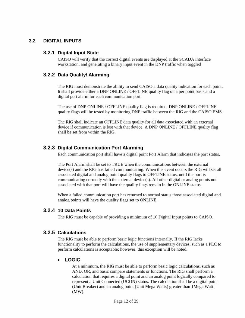
3.2 DIGITAL INPUTS
3.2.1 Digital Input State
CAISO will verify that the correct digital events are displayed at the SCADA interface
workstation, and generating a binary input event in the DNP traffic when toggled
3.2.2 Data Quality/ Alarming
The RIG must demonstrate the ability to send CAISO a data quality indication for each point.
It shall provide either a DNP ONLINE / OFFLINE quality flag on a per point basis and a
digital port alarm for each communication port.
The use of DNP ONLINE / OFFLINE quality flag is required. DNP ONLINE / OFFLINE
quality flags will be tested by monitoring DNP traffic between the RIG and the CAISO EMS.
The RIG shall indicate an OFFLINE data quality for all data associated with an external
device if communication is lost with that device. A DNP ONLINE / OFFLINE quality flag
shall be set from within the RIG.
3.2.3 Digital Communication Port Alarming
Each communication port shall have a digital point Port Alarm that indicates the port status.
The Port Alarm shall be set to TRUE when the communications between the external
device(s) and the RIG has failed communicating. When this event occurs the RIG will set all
associated digital and analog point quality flags to OFFLINE status, until the port is
communicating correctly with the external device(s). All other digital or analog points not
associated with that port will have the quality flags remain in the ONLINE status.
When a failed communication port has returned to normal status those associated digital and
analog points will have the quality flags set to ONLINE.
3.2.4 10 Data Points
The RIG must be capable of providing a minimum of 10 Digital Input points to CAISO.
3.2.5 Calculations
The RIG must be able to perform basic logic functions internally. If the RIG lacks
functionality to perform the calculations, the use of supplementary devices, such as a PLC to
perform calculations is acceptable; however, this exception will be noted.
LOGIC
At a minimum, the RIG must be able to perform basic logic calculations, such as
AND, OR, and basic compare statements or functions. The RIG shall perform a
calculation that requires a digital point and an analog point logically compared to
represent a Unit Connected (UCON) status. The calculation shall be a digital point
(Unit Breaker) and an analog point (Unit Mega Watts) greater than 1Mega Watt
(MW).

Page 13 of 29
The following is an example of a typical UCON calculation.
UCON = (Digital Point = True) and (Unit MW > 1).
Calculating multiple digital together using digital operands of OR, AND logic will be
tested
Summing multiple analog points together with operands of Add, Subtraction,
Multiplication, and Division will also be tested.
Section Complete RIG Owner______________ Date______________
CAISO_________________ Date______________
Comments:
_____________
______________________________________________________________________________
______________________________________________________________________________

Page 14 of 29
3.3 ANALOG OUTPUTS (SETPOINT) (SENT FROM CAISO EMS)
CAISO well send the test device multiple SETPOINT for AGC control, and test the time it
will take the RIG to accept and retransmit the SETPOINT.
Section Complete RIG Owner______________ Date______________
CAISO_________________ Date______________
Comments:
3.4 COMMUNICATION TESTING
3.4.1 Loss of Power
The RIG will have its power supply terminated to simulate power failure. After the power is
restored to the RIG, the RIG will be checked for restoration of application functionality and
its ability to reconnect to the CAISO EMS after power failure.
3.4.2 Restart
The RIG will be safely shut down, and restarted to check for reliability.
Section Complete RIG Owner______________ Date______________
CAISO_______________________ Date______________
Comments:
______

Page 15 of 29
3.5 CONNECTIVITY TESTING
3.5.1 Tracking
During the 5 days of testing the CAISO will track lost and reestablished connectivity
occurrences. At the end of the 5 day test the CAISO will total the amount of time that
connectivity was lost. This time divided by the total time for 5 days will represent a “percent
availability”.
3.5.2 Failure Rate
Communication between the EMS test system and the RIG must be active for 99.7 percent of
the time and not have a single communication failure lasting greater then 5 minutes. The RIG
will only be allowed a reasonable number of communication drops during the tracking period.
CAISO engineers have the responsibility to track, analyze, and amend any test procedure as
they see fit, to test the functionality and reliability of the test device.
Section Complete RIG Owner______________ Date______________
CAISO_________________ Date______________
Comments:

Page 16 of 29
Remote Intelligent Gateway (RIG)
Security Procedures

Page 17 of 29
Copyright © 2001 CALIFORNIA INDEPENDENT SYSTEM OPERATOR. All rights reserved. This document contains proprietary information. All information contained herein shall be kept in confidence, and shall not be divulged to persons other than CALIFORNIA INDEPENDENT SYSTEM
OPERATOR employees authorized by the nature of their responsibilities to receive such information, or individuals and organizations authorized by CALIFORNIA INDEPENDENT SYSTEM
OPERATOR in accordance with existing policy regarding release of company information.
All information in this document is subject to change without notice. This is a preliminary document and may be changed substantially prior to final release. This document is provided for informational purposes only and CALIFORNIA INDEPENDENT SYSTEM OPERATOR makes no warranties, either express or implied, in this document. The entire risk of the use or the results of the use of this document remains with the user.

Page 18 of 29
REVISION HISTORY
Date Version Description
01/31/02 1.0 Initial version taken from other Project SATs
02/25/02 1.1 Edited for formatting and removal of optional requirements
04/09/02 1.2 Editing changes with regards to required tests
08/01/02 1.3 Changes made based on the type of SSL implementation
08/22/02 1.4 Implemented sign off section for vendors regarding hardware/software changes that require re-certification.
10/27/08 2.1 Review and update to reflect shift to basic assurance requirements for RIGs.
11/4/08 2.2 Updated to remove unnecessary and infeasible test cases
Author: CUDA Technical Team

Page 19 of 29
1 PURPOSE
The purpose of this document is to define the RIG Validation Test plan for the security subsystem.
The CAISO test team can use these test cases to ascertain that the RIG meets the requirements as
stated in the RIG Technical Requirements, ISO Information Security section.
Note: The sample tests included in this document suggest a few of many ways that this testing can be
accomplished. Without developing specific test cases on an individual basis, it is impossible to
provide a single test that will encompass all technologies.
2 REQUIRED TEST CASES
The test cases below require device-based certificates and keys. The CAISO Information Security
group will provide the necessary certificates to be installed onto the RIG for testing.
2.1 CERTIFICATE RENEWAL
This tests the ability to request and install a new certificate on the RIG.
Prerequisites:
The complete certificate chain and a certificate for the RIG must be loaded prior to beginning this
test.
Procedure:
1. Issue a certificate request from the RIG, utilizing a new key pair file, and extract the request
from the device.
2. CAISO Information Security will process the CSR and return a certificate.
3. Install the certificate onto the device.
4. Delete the old certificate and corresponding key (if it is not overwritten in the process of
generating a new key pair/ CSR).
5. Attempt to establish a new session with the client device.
6. Verify that a session can be established, and note the certificate serial number has changed in
relation to the new certificate.
7. Verify that the appropriate serial number is recorded in the device’s audit log.
8. Provide CAISO with an instruction manual on how to perform a Certificate Renewal.
Acceptance:
Changing the keys and the certificate of a high assurance certified device is possible. After successful
re-keying, the device will use its new key and certificate to communicate with other high assurance
devices.
Section Complete Vendor______________ Date______________
ISO_________________ Date______________

Page 20 of 29
2.2 NEW CA
Note that there are two tests in this procedure:
1) This is a stand-alone test that ensures if the client device has a certificate from a new issuing CA,
the RIG can still communicate with it as long as it ultimately chains to the same root CA. This
test involves the following steps:
Generate a certificate request from the RIG device.
CAISO Information Security will process the request, and return a new certificate
Ensure you are using the new issuing CA certificate located on our website under:
http://www.caiso.com/participate/Pages/MeteringTelemetry/Default.aspx
Install the CyberTrust ISO Issuing Root Certificate, CyberTrust ISO Issuing Certificate and
the Device Certificate into the client device in the proper location.
Establish a secure session with the RIG.
Note that this proves successful.
2) Repeat the test entitled 2.1 Certificate Renewal, but issue the certificate from a new CA for the
RIG being tested.
Generate a new certificate request from the RIG.
CAISO Information Security will process the certificate request from the new CA, and return
it along with the CA certificate to the vendor.
Once the new certificate and CA certificates are received, the Vendor should install the
certificates in the RIG.
Attempt to connect to the client device certified from the old CA.
Acceptance:
In the first scenario, the RIG can securely communicate with the client device whose certificate was
issued by a new authorized CA. In the second scenario, the RIG can communicate with the client
device after going through the certificate renewal process involving a new CA.
Note:
The CA in this configuration represents an issuing CA.
Section Complete Vendor______________ Date______________
ISO_________________ Date______________

Page 21 of 29
2.3 NEW ROOT CA
This test demonstrates that units with different root CAs can securely communicate with each other
when trusted certificates are implemented in both devices.
Procedure:
1. Ensure a valid certificate, issuing and root certificate is installed on the RIG device being tested.
2. Load the root certificate of the CAISO’s system onto the RIG.
3. On CAISO’s system, ensure a valid certificate, issuing and root certificate is installed.
4. Load the root certificate of the RIG system onto CAISO’s system.
5. Attempt to establish communication between the RIG and CAISO’s system and verify that it
succeeds.
Acceptance:
The RIG software can communicate with other devices that are certified by other trusted root CAs.
Section Complete Vendor______________ Date______________
ISO_________________ Date______________

Page 22 of 29
2.4 ENCRYPTION VERIFICATION
This test demonstrates that the communication between the RIG being tested and CAISO’s system is
encrypted.
Procedure:
1. Using valid certificates, establish a secure session between the RIG being tested and CAISO’s
system.
2. Read and write data between the two units.
3. Use a tcpdump of the communication between the two RIGs to ensure that the
communication is encrypted. Use the following syntax:
Tcpdump –X –s 2048 –i <interface number, i.e. tu1> host <IP address of RIG>
The interface number can be obtained by running a infconfig –a on the client system
*Also note the agreed ciphers logged in the Audit file at the time of the initial connection
Acceptance:
The snooping of the communication line must show valid encrypted data, and only approved ciphers
available for negotiation.
Section Complete Vendor______________ Date______________
ISO_________________ Date______________

Page 23 of 29
2.5 SESSION KEY RENEWAL: EXPIRED OR REVOKED CERTIFICATES
This test demonstrates that sessions will not be renewed if the client’s certificate is expired or
revoked. This test may require some manipulation of renegotiation time on one of the units
participating in the test in the best interest of time.
Note: This test case may not be possible if the EMS system disables the session.
Procedure:
1. Using a valid certificate in the client device that is scheduled to expire within 25 hours (noting the
date and time of expiration), establish a session with the RIG.
2. Note the interval period and determine the interval at which renegotiation occurs (i.e. every hour,
every half hour, ten minutes, etc.)
3. Read and write data between the units (heartbeat counter)
4. Maintain the session, and once renegotiation has occurred after the certificate’s expiration,
confirm that the session is terminated as part of the automatic session renewal process
(renegotiation). (Note: Forcing renegotiation to occur once you know the certificate is expired
will expedite this process.)
5. Confirm that the RIG shows the appropriate messages regarding the failure to renew the session
in its audit logs.
The remaining test cases are OPTIONAL and not required:
6. Install a certificate on the client device that is contained on a certificate revocation list (CRL).
7. Install the CRL containing the revoked certificate on the RIG, and confirm that a session cannot
be established after session renegotiation occurs.
Acceptance:
The RIG should terminate sessions due to an invalid certificate (either expired or revoked). The audit
log must show a message regarding failure to renew the session.
Section Complete Vendor______________ Date______________
ISO_________________ Date______________

Page 24 of 29
2.6 OPTIONAL TEST CASE: CAISO CRL
Procedure:
1. Issue a CRL that does not include a revocation for the certificates of the two communicating
parties.
2. Establish a session between the two parties (RIG and the CAISO client device).
3. Verify that a session is successfully established.
4. Terminate the session.
5. Issue a CRL that contains the serial number of the CAISO client device’s certificate.
6. Load the CRL into the system of the RIG.
7. Establish a session between the two parties.
8. Verify that a session cannot be established.
9. Verify an audit log entry of the failed attempt.
Acceptance:
In step 3, the communicating parties successfully establish a session. In step 7 the session cannot be
established and the reason for failure is noted as revoked certificate. An audit record shows a failed
attempt to establish a session using a revoked certificate.
Section Complete Vendor______________ Date______________
ISO_________________ Date______________

Page 25 of 29
APPENDIX A
RTU OWNER VALIDATION REQUEST FORM
Contact Information
Company Name:
Request Date:
Main Contact:
Name of Test Device:
Phone number:
Type of Device:
Email address:
Pre-test information
Test Remotely
Test at CAISO
Device IP
ECN IP
Testing Schedule
Initial Meeting Data
Test Database Due Date
Block Diagram Due Date
Testing Date
RTU Owner Comments
Questions:
Device Exceptions:

Page 26 of 29
Section List the section and Description of exception
.
Return to:
Energy Data Acquisition Specialists (EDAS) [email protected] 916-608-5826

Page 27 of 29
APPENDIX B
DISCREPANCY REPORT
A-1 Discrepancy Tracking Classifications
The following is a description of the Discrepancy Classification. Each discrepancy MUST be
assigned a classification and a number.
Emergency – Class 1
Testing is stopped due to a fundamental issue that needs to be corrected before re-testing.
High Priority – Class 2 Testing can continue but with workaround(s) and/or reduced functionality. The supplier/ RTU Owner
must evaluate the discrepancy and correct it before the solution can be validated. The CAISO will
determine the need to re-test prior to validation.
Medium Priority – Class 3 Testing can continue but with minimal workaround(s) and/or operator intervention. The system can
be validated once the issue is resolved. The CAISO will determine the need to re-test prior to
validation.

Page 28 of 29
DDIISSCCRREEPPAANNCCYY RREEPPOORRTT FFoorrmm California Independent Systems Operator
Project No. _______________
Author Variance No.
Software Hardware Communications RTU
Variance Class Emergency High Medium Low
Description of Problem:
_______________________________________________________________________________________
Resolution:
_______________________________________________________________________________________
Corrected/Repaired By Date Author's Concurrence

Page 29 of 29
APPENDIX C
The testing database will be sent electronically through email or pick up from the CAISO.