Embed Size (px)
Citation preview

4
New SACE Tmax XT.XTraordinary completeness of range.
Here are the 4 new SACE Tmax XT frames for you:– the small XT1 up to 160A; – the high-performing XT2 up to 160A; – the reliable XT3 up to 250A; – the powerful XT4 up to 250A.

1/21SDC210033D0202
XT1Size(G2.1) [A] 160Poles [No.] 3, 4Rated service voltage, Ue(G2.4) (AC) 50-60Hz [V] 690
(DC) [V] 500Rated insulation voltage, Ui(G2.5) [V] 800Rated impulse withstand voltage, Uimp(G2.6) [kV] 8Versions Fixed, Plug-in(2) Breaking capacities according to IEC 60947-2 B C N S HRated ultimate short-circuit breaking capacity, Icu(G2.7)
Icu @ 220-230-240V 50-60Hz (AC) [kA] 25 40 65 85 100Icu @ 380V 50-60Hz (AC) [kA] 18 25 36 50 70Icu @ 415V 50-60Hz (AC) [kA] 18 25 36 50 70Icu @ 440V 50-60Hz (AC) [kA] 15 25 36 50 65Icu @ 500V 50-60Hz (AC) [kA] 8 18 30 36 50Icu @ 525V 50-60Hz (AC) [kA] 6 8 22 35 35Icu @ 690V 50-60Hz (AC) [kA] 3 4 6 8 10Icu @ 250V (DC) 2 poles in series [kA] 18 25 36 50 70Icu @ 500V (DC) 2 poles in series [kA] – – – – –Icu @ 500V (DC) 3 poles in series(3) [kA] 18 25 36 50 70
Rated service short-circuit breaking capacity, Ics(G2.8)
Ics @ 220-230-240V 50-60Hz (AC) [kA] 100% 100% 75% (50) 75% 75%Ics @ 380V 50-60Hz (AC) [kA] 100% 100% 100% 100% 75%Ics @ 415V 50-60Hz (AC) [kA] 100% 100% 100% 75% 50% (37.5)Ics @ 440V 50-60Hz (AC) [kA] 75% 50% 50% 50% 50%Ics @ 500V 50-60Hz (AC) [kA] 100% 50% 50% 50% 50%Ics @ 525V 50-60Hz (AC) [kA] 100% 100% 50% 50% 50%Ics @ 690V 50-60Hz (AC) [kA] 100% 100% 75% 50% 50%Ics @ 250V (DC) 2 poles in series [kA] 100% 100% 100% 100% 75%Ics @ 500V (DC) 2 poles in series [kA] – – – – –Ics @ 500V (DC) 3 poles in series(3) [kA] 100% 100% 100% 100% 75%
Rated short-circuit making capacity, Icm(G2.10)
Icm @ 220-230-240V 50-60Hz (AC) [kA] 52.5 84 143 187 220Icm @ 380V 50-60Hz (AC) [kA] 36 52.5 75.6 105 154Icm @ 415V 50-60Hz (AC) [kA] 36 52.5 75.6 105 154Icm @ 440V 50-60Hz (AC) [kA] 30 52.5 75.6 105 143Icm @ 500V 50-60Hz (AC) [kA] 13.6 36 63 75,6 105Icm @ 525V 50-60Hz (AC) [kA] 9.18 13.6 46.2 73.5 73.5Icm @ 690V 50-60Hz (AC) [kA] 4.26 5.88 9.18 13.6 17
Breaking capacities according to NEMA-AB1@ 240V 50-60Hz (AC) [kA] 25 40 65 85 100@ 480V 50-60Hz (AC) [kA] 8 18 30 36 65
Utilisation Category (IEC 60947-2) AReference Standard IEC 60947-2Isolation behaviour Mounted on DIN rail DIN EN 50022Mechanical life(G2.14) [No. Operations] 25000
[No. Hourly operations] 240Electrical life @ 415 V (AC)(G2.13) [No. Operations] 8000
[No. Hourly operations] 120Dimensions - Fixed(Width x Depth x Height)
H
WD
3 poles [mm] 76.2 x 70 x 130
4 poles [mm] 101.6 x 70 x 130
Total opening timeCircuit-breaker with shunt opening release [ms] 15Circuit-breaker with undervoltage release [ms] 15
Trip units for power distributionTMD/TMATMDEkip LS/IEkip IEkip LSIEkip LSIGEkip E
Trip units for motor protectionMF/MAEkip M-IEkip M-LIUEkip M-LRIU
Trip units for generator protectionTMGEkip G-LS/I
Trip units for oversized Neutral ProtectionEkip N-LS/I
Interchangeable protection trip unitsWeight Fixed 3/4 poles [kg] 1.1 / 1.4
Plug in (EF terminals) 3/4 poles [kg] 2.21 / 2.82Withdrawable (EF terminals) 3/4 poles [kg]
(1) 90kA@690V only for XT4 160. Available shortly, please ask ABB SACE (3) XT1 500V DC 4 poles in series Complete circuit-breaker(2) XT1 plug-in In max=125A (4) XT4 750V DC please ask ABB SACE for availability Loose trip unit
Construction characteristics
1/31SDC210033D0202
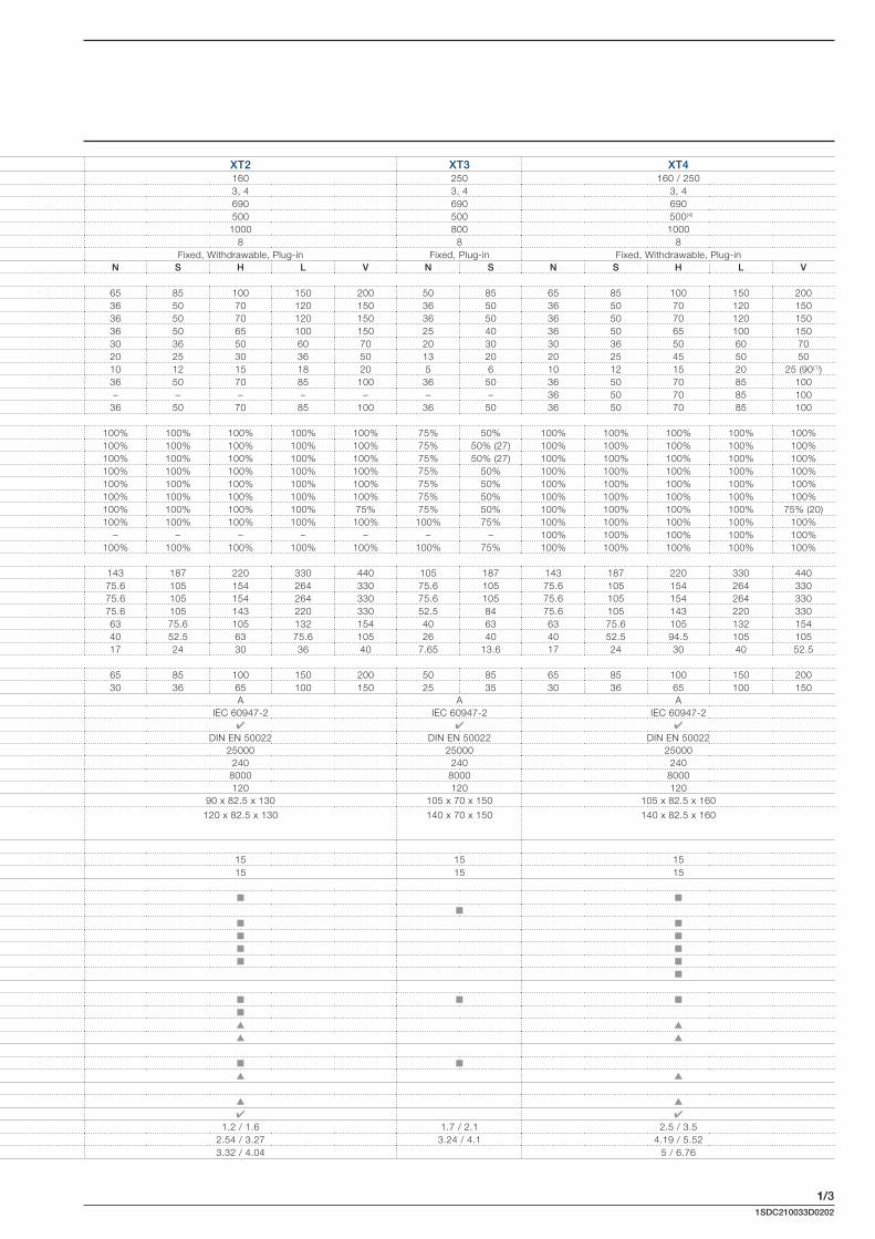
XT2 XT3 XT4160 250 160 / 2503, 4 3, 4 3, 4690 690 690500 500 500(4)
1000 800 10008 8 8
Fixed, Withdrawable, Plug-in Fixed, Plug-in Fixed, Withdrawable, Plug-inN S H L V N S N S H L V
65 85 100 150 200 50 85 65 85 100 150 20036 50 70 120 150 36 50 36 50 70 120 15036 50 70 120 150 36 50 36 50 70 120 15036 50 65 100 150 25 40 36 50 65 100 15030 36 50 60 70 20 30 30 36 50 60 7020 25 30 36 50 13 20 20 25 45 50 5010 12 15 18 20 5 6 10 12 15 20 25 (90(1))36 50 70 85 100 36 50 36 50 70 85 100– – – – – – – 36 50 70 85 100
36 50 70 85 100 36 50 36 50 70 85 100
100% 100% 100% 100% 100% 75% 50% 100% 100% 100% 100% 100%100% 100% 100% 100% 100% 75% 50% (27) 100% 100% 100% 100% 100%100% 100% 100% 100% 100% 75% 50% (27) 100% 100% 100% 100% 100%100% 100% 100% 100% 100% 75% 50% 100% 100% 100% 100% 100%100% 100% 100% 100% 100% 75% 50% 100% 100% 100% 100% 100%100% 100% 100% 100% 100% 75% 50% 100% 100% 100% 100% 100%100% 100% 100% 100% 75% 75% 50% 100% 100% 100% 100% 75% (20)100% 100% 100% 100% 100% 100% 75% 100% 100% 100% 100% 100%
– – – – – – – 100% 100% 100% 100% 100%100% 100% 100% 100% 100% 100% 75% 100% 100% 100% 100% 100%
143 187 220 330 440 105 187 143 187 220 330 44075.6 105 154 264 330 75.6 105 75.6 105 154 264 33075.6 105 154 264 330 75.6 105 75.6 105 154 264 33075.6 105 143 220 330 52.5 84 75.6 105 143 220 33063 75.6 105 132 154 40 63 63 75.6 105 132 15440 52.5 63 75.6 105 26 40 40 52.5 94.5 105 10517 24 30 36 40 7.65 13.6 17 24 30 40 52.5
65 85 100 150 200 50 85 65 85 100 150 20030 36 65 100 150 25 35 30 36 65 100 150
A A AIEC 60947-2 IEC 60947-2 IEC 60947-2
DIN EN 50022 DIN EN 50022 DIN EN 5002225000 25000 25000
240 240 2408000 8000 8000120 120 120
90 x 82.5 x 130 105 x 70 x 150 105 x 82.5 x 160
120 x 82.5 x 130 140 x 70 x 150 140 x 82.5 x 160
15 15 1515 15 15
1.2 / 1.6 1.7 / 2.1 2.5 / 3.52.54 / 3.27 3.24 / 4.1 4.19 / 5.523.32 / 4.04 5 / 6.76

1/4
1SD
C21
0A20
F000
1
1SDC210033D0202
Construction characteristics
The references in round brackets (Gx.x) in the technical catalogue refer to the Glossary in the final charter of the technical catalogue.
All the moulded-case circuit-breakers in the SACE Tmax XT family are realized in accordance with the following construction characteristics:
double insulation(G1.5);
positive operation(G1.6);
isolation behaviour(G1.7);
electromagnetic compatibility(G1.8);
tropicalization(G1.9);
impact and vibration resistance(G1.10);
power supply from the top towards the bottom or vice versa;
versatility of the installation. It is possible to mount the circuit-breaker in horizontal, vertical, or lying down position without any derating of the rated characteristics;
no nominal performance derating for use up to an altitude of 2000m. Above 2000m, the proper-ties of the atmosphere (composition of the air, dielectric strength, cooling power and pressure) change, having an impact on the main parameters which define the circuit-breaker. The table below gives the changes to the main performance parameters;
Altitude 2000m 3000m 4000m 5000m
Rated employ voltage, Ue [V] 690 600 540 470
Rated uninterrupted current % 100 98 93 90
the SACE Tmax XT circuit-breakers can be used in environments where the temperature is between -25°C and +70°C and stored in environments where the temperature is between -40°C and +70°C. To use temperatures other than 40°C, see the “Temperature Performances” paragraph of the Characteristic Curves and the technical information chapter;
different degrees of protection IP (International Protection)(G 1.11);
Circuit-breaker
With front
Without front(1)
With Front for lever
-FLD-
With rotary
Handles
With transmitted rotary handle and accessory IP54
With high terminal
covers HTC
With low terminal
covers LTC
A IP40 IP20 IP40 IP40 IP54 IP40 IP40
B IP20 IP20 IP20 IP20 IP20 IP40 IP40
C NC NC NC NC NC IP40 IP30(1) During the installation of electrical accessories NC Not classifiable
Accessories
Motor operatorMOD, MOE or MOE-E
Residual current devices
Residual current from switchboard
RCQ020
Automatic Transfer Switch ATS021
and ATS022
On Front IP30 IP40 IP41 IP40
all the circuit-breakers in the XT family are fitted with a test pushbutton which allows the release test to be done. This test must be carried out with the circuit-breaker closed and with no current.
Positive operation
Installation positions
Protection degrees
Test pushbutton

1/6
9
3
4
13
1
7
7
6
5
14
10
156
10
3471
76
5
14
13
1
9
11
8
2
12
15
1SDC210033D0202
The characteristics of the circuit-breaker are given on the rating nameplate on the front of the circuit-breaker, and on the side rating plate.
Front label
1 Name of the circuit-breaker and performance level(*)
2 In: rated current of the circuit-breaker(*)
3 Uimp: rated impulse withstand voltage(*)
4 Ui: insulation voltage(*)
5 Ics rated short-circuit duty breaking capacity(*)
6 Icu: rated ultimate short-circuit breaking capacity(*)
7 Ue: rated service voltage(*)
8 Symbol of isolation behaviour(*)
9 Reference Standard IEC 60947-2(*)
10 Serial number11 Anti-forgery logo12 Test pushbutton13 CE marking14 Utilisation Category15 Reference Standard NEMA-AB1(*) In compliance with the IEC 60947-2 Standard
Side label
Identifi cation of the SACE Tmax XT circuit-breakers

2/21SDC210033D0202
The SACE Tmax XT family ranges
The SACE Tmax XT moulded-case circuit-breaker family complies with different installation require-ments. Circuit-breakers are available with trip units dedicated to different applications, such as power distribution, generator protection, motor protection and oversized neutral protection. Some of these circuit-breakers can also be used in communication systems and plants that function at 400Hz. Switch-disconnectors are also available.
In = Rated uninterrupted current(G2.2) XT1 160 XT2 160 XT3 250 XT4 250
Power distribution
Thermomagnetic trip units
TMD 16…160 63…250
TMD/TMA 1.6…160 16…250
Electronic trip units
Ekip LS/I 10…160 40…250
Ekip I 10…160 40…250
Ekip LSI 10…160 40…250
Ekip LSIG 10…160 40…250
Ekip E-LSIG 40…250
Motor protection
Magnetic trip units
MF/MA 1…100(1) 100…200(1) 10…200(1)
Electronic trip units
Ekip M-I 20…100(1)
Ekip M-LIU 25…100(1) 40…160(1)
Ekip M-LRIU 25…100(1) 40…200(1)
Generator Protection
Thermomagnetic trip units
TMG 16…160 63…250
Electronic trip units
Ekip G-LSI 10…160 40…250
Oversized Neutral Protection 160%
Electronic trip units
Ekip N-LS/I 10…100(2) 40…160(2)
Switch-disconnectors
Special applications
400Hz
Communication(1) Only 3 poles version(2) Only 4 poles version

2/31SDC210033D0202
Circuit-breakers for power distributionMain characteristics
SACE Tmax XT moulded-case circuit-breakers are the ideal solution for all distribution levels, from the main low voltage switchboard to the subswitchboards in the installation. They feature high specific let-through current peak and energy limiting characteristics that allow the circuits and equipment on the load side to be sized in an optimum way. SACE Tmax XT circuit-breakers with thermomagnetic and electronic trip units protect against overloads, short-circuits, earth faults and indirect contacts in low voltage distribution networks.
The SACE Tmax XT family of moulded-case circuit-breakers can be equipped with: thermomagnetic trip units(G3.2), for direct and alternating current network protection, using the
physical properties of a bimetal and an electromagnet to detect the overloads and short-circuits; electronic trip units(G3.4), for alternating current network protection. Releases with microproc-
essor technology obtain protection functions that make the operations extremely reliable and accurate. The power required for operating them correctly is supplied straight from the current sensors of the releases. This ensures that they trip even in single-phase conditions and on a level with the minimum setting.
The electronic protection trip unit consists of:
– 3 or 4 current sensors (current transformers); – a protection unit; – an opening solenoid (built into the electronic trip unit).
Characteristics of Electronic trip units SACE Tmax XT
Operating temperature -25°C…+70°C
Relative humidity 98%
Self-supplied 0.2xIn (single phase)(1) (2)
Auxiliary supply (where applicable) 24V DC ± 20%
Operating frequency 45…66Hz or 360…440Hz
Electromagnetic compatibility IEC 60947-2 Annex F(1) 0.32 x In for Ekip N-LS/I(2) For 10A: 0.4In

2/41SDC210033D0202
Characteristics of circuit-breakers for power distributionXT1 XT2 XT3 XT4
Size(G2.1) [A] 160 160 250 160/250
Poles [Nr.] 3, 4 3, 4 3, 4 3, 4
Rated service voltage, Ue(G2.4) (AC) 50-60Hz [V] 690 690 690 690
(DC) [V] 500 500 500 500
Rated insulation voltage, Ui(G2.5) [V] 800 1000 800 1000
Rated impulse withstand voltage, Uimp(G2.6) [kV] 8 8 8 8
Versions Fixed, Plug-in
Fixed, Withdrawable, Plug-in
Fixed, Plug-in
Fixed, Withdrawable, Plug-in
Breaking capacities B C N S H N S H L V N S N S H L V
Trip units Thermomagnetic Thermomagnetic, Electronic
Thermomag-netic
Thermomagnetic, Electronic
TMD/TMA
TMD
Ekip LS/IIn = 10A, 25A, 63A,
100A, 160AIn = 40A, 63A, 100A,
160A, 250A
Ekip IIn = 10A, 25A, 63A,
100A, 160AIn = 40A, 63A, 100A,
160A, 250A
Ekip LSIIn = 10A, 25A, 63A,
100A, 160AIn = 40A, 63A, 100A,
160A, 250A
Ekip LSIGIn = 10A, 25A, 63A,
100A, 160AIn = 40A, 63A, 100A,
160A, 250A
Ekip E-LSIGIn = 40A, 63A, 100A,
160A, 250A
Interchangeability
Complete circuit-breaker
Circuit-breakers for power distributionMain characteristics
2/51SDC210033D0202
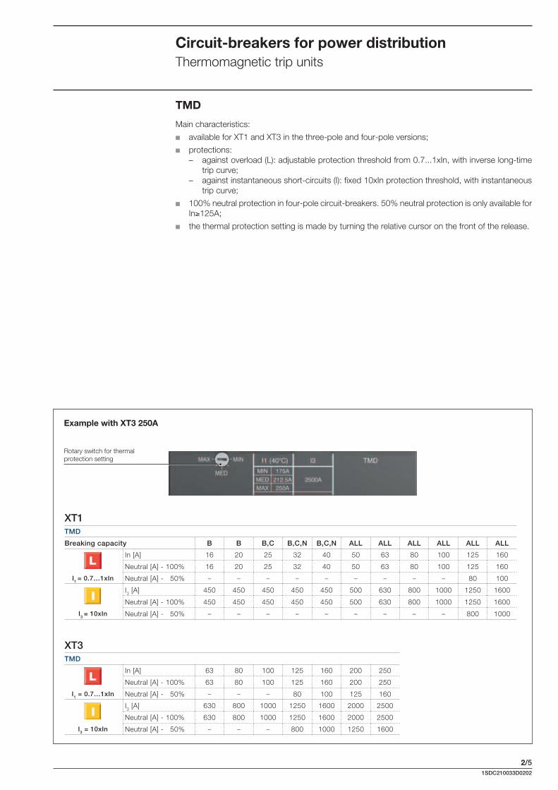
TMD
Main characteristics:
available for XT1 and XT3 in the three-pole and four-pole versions;
protections: – against overload (L): adjustable protection threshold from 0.7...1xIn, with inverse long-time
trip curve;– against instantaneous short-circuits (I): fi xed 10xIn protection threshold, with instantaneous
trip curve;
100% neutral protection in four-pole circuit-breakers. 50% neutral protection is only available for In 125A;
the thermal protection setting is made by turning the relative cursor on the front of the release.
Circuit-breakers for power distributionThermomagnetic trip units
XT1TMD
Breaking capacity B B B,C B,C,N B,C,N ALL ALL ALL ALL ALL ALL
In [A] 16 20 25 32 40 50 63 80 100 125 160
Neutral [A] - 100% 16 20 25 32 40 50 63 80 100 125 160
I1 = 0.7…1xIn Neutral [A] - 50% – – – – – – – – – 80 100
I3 [A] 450 450 450 450 450 500 630 800 1000 1250 1600
Neutral [A] - 100% 450 450 450 450 450 500 630 800 1000 1250 1600
I3 = 10xIn Neutral [A] - 50% – – – – – – – – – 800 1000
XT3TMD
In [A] 63 80 100 125 160 200 250
Neutral [A] - 100% 63 80 100 125 160 200 250
I1 = 0.7…1xIn Neutral [A] - 50% – – – 80 100 125 160
I3 [A] 630 800 1000 1250 1600 2000 2500
Neutral [A] - 100% 630 800 1000 1250 1600 2000 2500
I3 = 10xIn Neutral [A] - 50% – – – 800 1000 1250 1600
Rotary switch for thermal protection setting
Example with XT3 250A

2/61SDC210033D0202
XT2TMD/TMA
In [A] 1.6(1) 2(1) 2.5(1) 3.2(1) 4(1) 5(1) 6.3(1) 8(1) 10(1) 12.5(1) 16 20 25 32 40 50 63 80 100 125 160
Neutral [A] - 100% 1.6 2 2.5 3.2 4 5 6.3 8 10 12.5 16 20 25 32 40 50 63 80 100 125 160
I1 = 0.7…1xIn Neutral [A] - 50% – – – – – – – – – – – – – – – – – – – 80 100
TMD 16 20 25 32 40 50 63 80 100 125 300 300 300 320
TMA 300…400
300…500
300…630
400…800
500…1000
625…1250
800…1600
Neutral [A] - 100% 16 20 25 32 40 50 63 80 100 125 300 300 300 320 300…400
300…500
300…630
400…800
500…1000
625…1250
800…1600
Neutral [A] - 50% – – – – – – – – – – – – – – – – – – – 400…800
1000…2000
(1) Available only as complete circuit-breaker
XT4TMD/TMA
In [A] 16 20 25 32 40 50 63 80 100 125 160 200 225 250
Neutral [A] - 100% 16 20 25 32 40 50 63 80 100 125 160 200 225 250
I1 = 0.7…1xIn Neutral [A] - 50% – – – – – – – – – 80 100 125 125 160
TMD 300 300 300 320
TMA 300…400
300…500
315…630
400…800
500…1000
625…1250
800…1600
1000…2000
1125…2250
1250…2500
Neutral [A] - 100% 300 300 300 320 300…400
300…500
315…630
400…800
500…1000
625…1250
800…1600
1000…2000
1125…2250
1250…2500
Neutral [A] - 50% – – – – – – – – – 315…630
500…1000
625…1250
625…1250
500…1000
TMD/TMA
Main characteristics:
available for XT2 and XT4 in the three-pole and four-pole versions;
protections: – against overload (L): adjustable protection threshold from 0.7...1xIn, with inverse long time
trip curve;– against instantaneous short-circuit (I): - fi xed protection threshold for In 32A, - adjustable threshold beteewn 8…10xIn for 40A, - adjustable threshold beteewn 6…10xIn for 50A, - adjustable threshold beteewn 5…10xIn for In 63A;
100% neutral protection in four-pole circuit-breakers. 50% neutral protection is only available for In 125A;
the thermal and magnetic protection settings are made by turning the relative cursors on the front of the release.
Circuit-breakers for power distributionThermomagnetic trip units
Rotary switch for magnetic protection setting
Rotary switch for thermal protection setting
Example with XT4 250A

2/71SDC210033D0202
Circuit-breakers for power distributionElectronic trip units
Ekip I
Main characteristics:
usable with the XT2 and XT4 circuit-breaker in the three-pole and four-pole versions;
protections:
– against instantaneous short-circuit (I): adjustable protection threshold from 1...10xIn, with instantaneous trip curve;
– of the neutral in four-pole circuit-breakers: - for In 100A in the OFF or ON positions, 50% and 100% of the phases can be selected; - for In<100A, neutral protection is fi xed at 100% of the phases and disableded by user;
manual setting using the relative dip-switches, which allow the settings to be made even when the trip unit is off;
LED: – LED lit with a steady green light indicating that the trip unit is supplied correctly. The LED
comes on when the current exceeds 0.2xIn; – LED with a steady red light, indicating that protection I has tripped; red LED light on connect-
ing Ekip TT or Ekip T&P accessories after circuit-breaker opening for “I protection” interven-tion;
– Ekip I is equipped with a trip coil disconnection protection device that detects whether the opening solenoid has disconnected. Signalling is made by the red LED fl ashing;
test connector on the front of the trip unit;– to connect the Ekip TT trip test unit, which allows trip test, LED test and signalling about
latest trip happened;– to connect the Ekip T&P unit, which allows the measurements to be read, the trip test to be
conducted and the I protection function test to be carried out;
self-supply from a minimum current of 0.2xIn up.
Ekip IProtection function Trip threshold Trip curve(1) Excludability Relation
Against short-circuits with adjustable treshold and instantaneous trip time
Manual setting:I3= 1, 1.5, 2, 2.5, 3, 3.5, 4.5,
5.5, 6.5, 7, 7.5, 8, 8.5, 9, 10xIn
Tolerance: ±20% I>4In ±10% I 4In
20ms Yes t = k
I protection LED
Test ConnectorDip switch for I protection function setting
Power-on LED
(1) Tollerances in case of: – self-powered trip unit at full power; – 2 or 3 phase power supply. In conditions other than those considered, the trip time is 60ms.
Slot for lead seal

2/81SDC210033D0202
Ekip LS/I
Main characteristics:
available for XT2 and XT4 in the three-pole and four-pole versions; protections:
– against overload (L): 0.4...1xIn adjustable protection threshold, with adjustable time trip curve;– against short-circuit with delay (S): 1...10xIn adjustable protection threshold, with adjustable
time trip curve (as an alternative to I protection);– against instantaneous short-circuit (I): 1...10xIn adjustable protection threshold, with instan-
taneous trip curve (as an alternative to S protection);– of the neutral in four-pole circuit-breakers:
- for In 100A can be selected in the OFF or ON positions, 50%, 100% of the phases;- for In <100A, neutral protection is fi xed at 100% of the phases and disableded by user;
manual setting using the relative dip-switches on the front of the trip unit, which allow the set-tings to be made even when the trip unit is off;
LED: – LED with steady green light indicating that the trip unit is supplied correctly. The LED comes
on when the current exceeds 0.2xIn; – red LED for each protection:
- L: LED with steady red light, indicates pre-alarm for current exceeding 0.9xI1;- L: LED with fl ashing red light, indicates alarm for current exceeding setted threshold;- LS/I: LED with steady red light, shows that the protection has tripped. After the circuit-
breaker has opened, connect the Ekip TT or Ekip T&P accessory to fi nd out which protec-tion function tripped the trip unit;
– Ekip LS/I is equipped with a trip coil disconnection detection device that detects whether the opening solenoid has disconnected. Signalling is made by all the red LEDs fl ashing simulta-neously;
test connector on the front of the release:– to connect the Ekip TT trip test unit, which allows trip test, LED test and signalling about
latest trip happened;– to connect the Ekip T&P unit, which allows the measurements to be read, the trip test to be
conducted and the protection functions test to be carried out; thermal memory which can be activated by Ekip T&P; self-supply from 0.2xIn minimum current up.
Ekip LS/IProtection function Trip threshold Trip curve(1) Excludability Relation Thermal memory
Against overloads with long inverse time delay trip according to IEC 60947-2 Standard
Manual setting:I1= 0.4...1xIn step 0.04
Tolerance: trip between 1.05…1.3 I1 (IEC 60947-2)
Manual setting:t1= 12-36s at I=3xI1Tolerance: ±10% up to 4xIn ±20% from 4xIn
– t = k/l2 Yes
Against short-circuits with indipendend time delay (t=k)
Manual setting:I2= 1-1.5-2-2.5-3-3.5-4.5-5.5-
6.5-7-7.5-8-8.5-9-10xIn
Tolerance: ±10%
t2= 0.1-0.2s
Tolerance: ±15% Yes t = k –
Against short-circuits with adjustable treshold and instantaneous trip time
Manual setting:I3= 1-1.5-2-2.5-3-3.5-4.5-5.5-
6.5-7-7.5-8-8.5-9-10xIn
Tolerance: ±10%
20ms Yes t = k –
Circuit-breakers for power distributionElectronic trip units
L, S, I protection LED Test Connector
Dip switch for LS/I protection function setting
Power-on LED
Dip switch for the trip curve selection
Dip switch for the selection between S protection function or I protection function
(1) Tollerances in case of: – self-powered trip unit at full power; – 2 or 3 phase power supply. In conditions other than those considered, the
following tollerance hold:
Protection Trip threshold Trip timeL release between 1.05 and 1.3 x I1 ±20%S ±10% ±20%I ±15% 60ms
Slot for lead seal
2/91SDC210033D0202
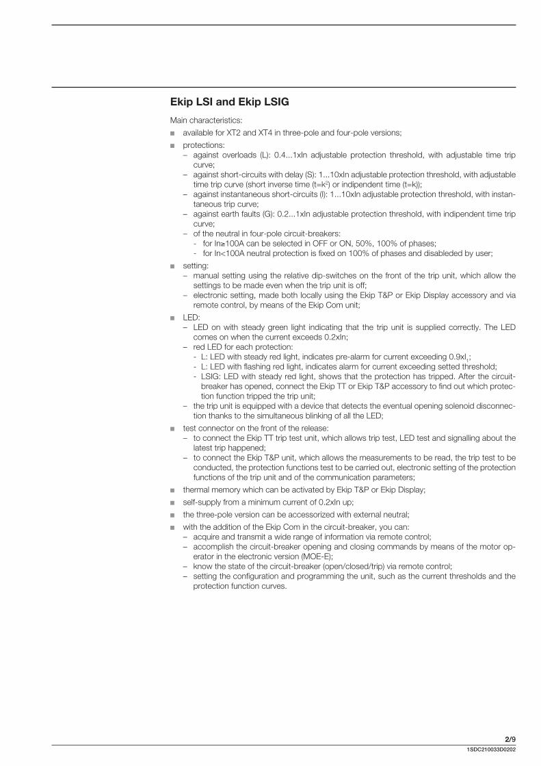
Ekip LSI and Ekip LSIG
Main characteristics:
available for XT2 and XT4 in three-pole and four-pole versions;
protections: – against overloads (L): 0.4...1xIn adjustable protection threshold, with adjustable time trip
curve;– against short-circuits with delay (S): 1...10xIn adjustable protection threshold, with adjustable
time trip curve (short inverse time (t=k2) or indipendent time (t=k));– against instantaneous short-circuits (I): 1...10xIn adjustable protection threshold, with instan-
taneous trip curve; – against earth faults (G): 0.2...1xIn adjustable protection threshold, with indipendent time trip
curve;– of the neutral in four-pole circuit-breakers: - for In 100A can be selected in OFF or ON, 50%, 100% of phases; - for In<100A neutral protection is fixed on 100% of phases and disableded by user;
setting: – manual setting using the relative dip-switches on the front of the trip unit, which allow the
settings to be made even when the trip unit is off;– electronic setting, made both locally using the Ekip T&P or Ekip Display accessory and via
remote control, by means of the Ekip Com unit;
LED: – LED on with steady green light indicating that the trip unit is supplied correctly. The LED
comes on when the current exceeds 0.2xIn;– red LED for each protection:
- L: LED with steady red light, indicates pre-alarm for current exceeding 0.9xI1;- L: LED with flashing red light, indicates alarm for current exceeding setted threshold;- LSIG: LED with steady red light, shows that the protection has tripped. After the circuit-
breaker has opened, connect the Ekip TT or Ekip T&P accessory to find out which protec-tion function tripped the trip unit;
– the trip unit is equipped with a device that detects the eventual opening solenoid disconnec-tion thanks to the simultaneous blinking of all the LED;
test connector on the front of the release:– to connect the Ekip TT trip test unit, which allows trip test, LED test and signalling about the
latest trip happened;– to connect the Ekip T&P unit, which allows the measurements to be read, the trip test to be
conducted, the protection functions test to be carried out, electronic setting of the protection functions of the trip unit and of the communication parameters;
thermal memory which can be activated by Ekip T&P or Ekip Display;
self-supply from a minimum current of 0.2xIn up;
the three-pole version can be accessorized with external neutral;
with the addition of the Ekip Com in the circuit-breaker, you can: – acquire and transmit a wide range of information via remote control; – accomplish the circuit-breaker opening and closing commands by means of the motor op-
erator in the electronic version (MOE-E); – know the state of the circuit-breaker (open/closed/trip) via remote control; – setting the configuration and programming the unit, such as the current thresholds and the
protection function curves.

2/101SDC210033D0202
Ekip LSI – Ekip LSIGProtection function Trip threshold Trip curve(1) Excludability Relation Thermal
memory
Against overloads with long inverse time delay trip according to IEC 60947-2 Standard
Manual setting:I1= 0.4...1xIn step 0.02
Tolerance: trip between 1.05…1.3 I1 (IEC 60947-2)
Manual setting:t1 = 3-12-36-60s at I=3xI1Tolerance: ±10% up to 4xIn ±20% from 4xIn
– t = k/l2 Yes
Electronic setting:I1= 0.4...1xIn step 0.01
Tolerance: trip between 1.05…1.3 I1 (IEC 60947-2)
Electronic setting:t1 = 3...60s at I=3xI1 step 0.5
Tolerance: ±10% up to 4xIn ±20% from 4xIn
– t = k/l2 Yes
Against short-circuits with inverse short (t=k/I2) or indipendent (t=k) time delay trip
Manual setting:I2 = 1-1.5-2-2.5-3-3.5-4.5-5.5-
6.5-7-7.5-8-8.5-9-10xIn
Tolerance: ±10%
Manual setting:t2= 0.05-0.10-0.20-0.40s
at 10xIn
Tolerance: ±10% up to 4xIn ±20% from 4xIn
Yes t = k/l2 –
Electronic setting:I2 = 1...10xIn step 0.1
Tolerance: ±10%
Electronic setting:t2 = 0.05...0.40s at 10xIn step 0.01
Tolerance: ±10% up to 4xIn ±20% from 4xIn
Yes t = k/l2 –
Manual setting:I2 = 1-1.5-2-2.5-3-3.5-4.5-5.5-
6.5-7-7.5-8-8.5-9-10xIn
Tolerance: ±10%
Manual setting:t2 = 0.05-0.1-0.2-0.4s
Tolerance: ±15% t2>100ms ±20% t2 100ms
Yes t = k –
Electronic setting:I2 = 1...10xIn step 0.1
Tolerance: ±10%
Electronic setting:t2 = 0.05...0.4s step 0.01
Tolerance: ±15% t2>100ms ±20% t2 100ms
Yes t = k –
Against short-circuits with adjustable threshold and instantaneous trip time
Manual setting:I3 = 1-1.5-2-2.5-3-3.5-4.5-5.5-
6.5-7-7.5-8-8.5-9-10xIn
Tolerance: ±20%
40ms Yes t = k –
Electronic setting:I3 = 1...10xIn step 0.1
Tolerance: ±10%40ms Yes t = k –
Against earth fault with independent time delay trip(2)
Manual setting:
I4 = 0.2-0.25-0.45-0.55-0.75- 0.8-1xIn
Tolerance: ±10%
Manual setting:t4 = 0.1-0.2-0.4-0.8s
Tolerance: ±15%Yes I2t = k –
Electronic setting:I4 = 0.2...1xIn step 0.02
Tolerance: ±10%
Electronic setting:t4 = 0.1...0.8s step 0.05
Tolerance: ±15%Yes I2t = k –
Circuit-breakers for power distributionElectronic trip units
L, S, I, G protection LED
Test connectorDip switch for the S trip curves selection
Power-on LED
Dip switch for LSIG protection function setting
Dip switch for the trip curve selection
Selection for remote or local setting
Selection for manual or electronic setting
(1) Tollerances in case of: – self-powered trip unit at full power; – 2 or 3 phase power supply. In conditions other than those considered,
the following tollerance hold:
Protection Trip threshold Trip timeL release between 1.05 and 1.3 x I1 ±20%S ±10% ±20%I ±15% 60msG ±15% ±20%
Slot for lead seal
(2) Protection G is inhibited for currents higher than 2 In.

2/111SDC210033D0202
Ekip E-LSIG
Main characteristics:
available for XT4 in three-pole and four-pole versions;
protections:– against overloads (L): 0.4...1xIn adjustable protection threshold, with adjustable time trip
curve;– against short-circuits with delay (S): 1...10xIn adjustable protection threshold, with adjustable
time trip curve;– against instantaneous short-circuits (I): 1...10xIn adjustable protection threshold, with instan-
taneous trip curve;– of the neutral in four-pole circuit-breakers;
measurements:– available from 0.2xIn in Vaux mode and starting from 0.5xIn in self supply mode; external
current or voltage transformers are not required. See table for ranges and accuracy;– Currents: three phases (L1, L2, L3), neutral (Ne) and earth fault;– Voltage: phase-phase, phase-neutral;– Power: active, reactive and apparent;– Power factor;– Frequency and peak factor;– Energy: active, reactive, apparent, counter;
setting:– manual setting using the relative dip-switches on the front of the trip unit, which allow the
settings to be made even when the trip unit is off;– electronic setting, made both locally using Ekip T&P or Ekip Display accessory and via remote
control, by means of the dialogue unit Ekip Com. The electronic setting have a wider range and a thicker regulation step.
Use of electronic setting allows other functions to be activated:- function for protection against earth faults (G): 0.2..1xIn adjustable protection threshold,
with a time constant trip curve;- over voltage protection 0.5…0.95 Un with a time constant trip curve;- under voltage protection 1.05…1.2 Un with a time constant trip curve;
LED:– LED on with steady green light indicating that the trip unit is supplied correctly. The LED
comes on when the current exceeds 0.2xIn;– red LED for each protection:
- L: LED with steady red light, indicates pre-alarm for current exceeding 0.9xI1;- L: LED with flashing red light, indicates alarm for current exceeding setted threshold;- fixed LED MAN/ELT show the kind of active parameters;- LSIG: LED with steady red light, shows that the protection has tripped. After the circuit-
breaker has opened, connect the Ekip TT or Ekip T&P accessory to find out which protec-tion function tripped the trip unit;
– the trip unit is equipped with a device that detects the eventual opening solenoid disconnec-tion thanks to the simultaneous blinking of all the LED;
test connector on the front of the release:– to connect the Ekip TT trip test unit, which allows trip test, LED test and signalling about the
latest trip happened;– to connect the Ekip T&P unit, which allows the measurements to be read, the trip test to be
conducted, the protection functions test to be carried out, electronic setting of the protection functions of the trip unit and of the communication parameters;
self-supply from a minimum current of 0.2xIn up; measurements starting from 0.5xIn; the three-pole version can be accessorized with external neutral current transformer and external
neutral voltage connection kit; with the addition of the Ekip Com in the circuit-breaker, you can:
– acquire and transmit a wide range of information via remote control;– accomplish the circuit-breaker opening and closing commands by means of the motor
operator in the electronic version (MOE-E);– know the state of the circuit-breaker (open/closed/trip) via remote control;– setting the configuration and programming the unit, such as the current thresholds and the
protection function curves.

2/121SDC210033D0202
Circuit-breakers for power distributionElectronic trip units
Ekip E-LSIGProtection function Trip threshold Trip curve(1) Excludability Relation Thermal
memory
Against overloads withlong inverse time delay tripaccording to IEC 60947-2
Manual setting:I1= 0.4...1xIn step 0.04
Tolerance: trip between 1.05…1.3 I1 (IEC 60947-2)
Manual setting:t1 = 12-36s at I=3xI1Tolerance: ±10% up to 4xIn ±20% from 4xIn
– t = k/l2 –
Electronic setting:I1= 0.4...1xIn step 0.01
Tolerance: trip between 1.05…1.3 I1 (IEC 60947-2)
Electronic setting:t1 = 3...60s at I=3xI1 step 0.5
Tolerance: ±10% up to 4xIn ±20% from 4xIn
– t = k/l2 Yes
Against short-circuits with inverse short (t=k/I2) or indipendent (t=k) time delay trip
Manual setting:I2 = OFF 3-6-9
Tolerance: ±10%
Manual setting:t2= 0.10-0.20s at 10xIn Yes t = k –
Electronic setting:I2 = 1...10xIn step 0.1
Tolerance: ±10%
Electronic setting:t2 = 0.05...1s at 10xIn step 0.01
Tolerance: ±10% up to 4xIn ±20% from 4xIn
Yes t = k/l2 –
Electronic setting:I2 = 1...10xIn step 0.1
Tolerance: ±10%
Electronic setting:t2 = 0.05...0.4s step 0.01
Tolerance: ±10% up to 4xIn ±20% from 4xIn
Yes t = k/l2 –
Against short-circuits with adjustable threshold and instantaneous trip time
Manual setting:I3 = OFF 1-3-4-7-9-10
Tolerance: ±20%40ms Yes t = k –
Electronic setting:I3 = 1...10xIn step 0.1
Tolerance: ±10%40ms Yes t = k –
Against earth fault with independent time delay trip(2)
Electronic setting:I4 = 0.2...1xIn step 0.02
Tolerance: ±10%
Electronic setting:t4 = 0.1...0.8s step 0.05s
Tolerance: ±15%Yes t = k/l2 –
UV
Standardadjustable constant time
Electronic setting:U8 = 0.5...0.95xUn step=0.01xUn
Tolerance: ±5%
Electronic setting:t8 = 0.1...5s step 0.1s
Tolerance: min (±20% ±100ms)Yes t = k –
OVAgainst overvoltage with adjustable constant time
Electronic setting:U9 = 1.05...1.2xUn step=0.01xUn
Tolerance: ±5%
Electronic setting:t9 = 0.1...5s step 0.1s
Tolerance: min (±20% ±100ms)Yes t = k –
Test connector
Power-on LED
(1) Tollerances in case of: – self-powered trip unit at full power; – 2 or 3 phase power supply. In conditions other than those considered,
the following tollerance hold:
Protection Trip threshold Trip timeL release between 1.05 and 1.3 x I1 ±20%S ±10% ±20%I ±15% 60msG ±15% ±20%
(2) Protection G is inhibited for currents higher than 2 In.
L, S, I protection LED LED for Electronic/Manual setting
Setting MAN/ELT
Tolerance: ±15% t2>100ms ±20% t2 100ms

2/131SDC210033D0202
Value Range Accuracy Specified measuring range
Current Phase current (I1, I2, I3, IN) 0 … 12 In Cl 1 0.2 … 1.2 In
Phase current minimum value
Phase current maximum value
Ground current (Ig) 0 … 4 In – –
Voltage Phase voltage runtime, max and min (V1N, V2N, V3N) (1)
0 … 828 V ±0.5% 100 … 400 V
Line voltage runtime, max and min(U12, U23, U31)
0 … 828 V ±0.5% 100 … 690 V
Power Active Phase power runtime, max and min(P1, P2, P3) (1)
-207 kW … 207 kW Cl 2 -207 kW … -1 kW1 kW … 207 kW
Total power runtime, max and min
-1 MW … 1 MW Cl2 -1 MW … -3 kW3 kW … 1 MW
Reactive Phase power runtime, max and min(Q1, Q2, Q3) (1)
-207 kvar … 207 kvar Cl 2 -207 kvar … -1 kvar1 kvar … 207 kvar
Total power runtime, max and min
-1 Mvar … 1 Mvar Cl 2 -1 Mvar … -3 kvar3 kvar … 1 Mvar
Apparent Phase power runtime, max and min(S1, S2, S3) (1)
0 … 207 kVA Cl 2 1 kVA … 207 kVA
Total power runtime, max and min
0 … 1 MVA Cl 2 3 kVA … 1 MVA
Energy Active Total energy 1 kWh … 2 TWh Cl 2 1 kWh … 2 TWh
Incoming energy
Outgoing energy
Reactive Total energy 1 kvarh … 2 Tvarh Cl 2 1 kvarh … 2 Tvarh
Incoming energy
Outgoing energy
Apparent Total energy 1 kVAh … 2 TVAh Cl 2 1 kVAh … 2 TVAh
Power quality Harmonic analisys (2) 11th (50 - 60Hz) – –
THD of phase L1, L2, L3 (2) 0 … 1000% ±10% 0 … 500%
Frequency runtime, max, min 45 … 66 Hz ±0.5% 45 … 66 Hz
PF of phase L1, L2, L3 (1) -1 … 1 ±2% -1 … -0.50.5 … 1
(1) Not available if Neutral is not connected(2) Available on demand by sending a Modbus command

2/141SDC210033D0202
PTC
PR212/CI
Motor
Circuit-breaker with magnetic only trip unit
Thermal relay
Contactor
Motor
Circuit-breaker with electronic trip unit Ekip M-LRIU
Contactor
Conventional system Advanced protection system
The safety and reliability of the solution are important aspects that must be considered when choosing and manufacturing the system for starting(G4.3 and G4.4) and monitoring motors.Start-up is a particularly critical phase for the motor itself and for the installation powering it. Even rated service needs to be adequately monitored and protected so as to deal with any faults that might occur.When it comes to direct starting, ABB SACE proposes two different solutions:
a conventional system with three poles a circuit-breaker equipped with a magnetic only trip unit for protection against short-circuits, a thermal relay for protection against overloads and phase failure or imbalance, and a contactor to operate the motor;
an advanced protection system which integrates all the protection and monitoring functions, and a contactor for operating the motor, in the circuit-breaker itself.
Several different factors must be considered when choosing and coordinating the protection and operating devices, e.g.:
the electrical specifications of the motor (type, power rating, efficiency, cos );
the starting type and diagram;
the fault current and voltage in the part of the network where the motor is installed.
Consult the QT7 Technical Application Paper: “The asynchronous three-phase motor: general infor-mation and ABB’s offer for coordinating the protections” for further details.The motor protection and operating devices must be chosen in accordance with the coordination tables provided by ABB either through documentation “Coordination tables” or on the web site: http://www.abbcontrol.fr/coordination_tables/.
Circuit-breakers for motors protectionMain characteristics

2/151SDC210033D0202
Characteristics of circuit-breakers for protecting motorsXT2 XT3 XT4
Size(G2.1) [A] 160 250 160/250
Poles [Nr.] 3 3 3
Rated service voltage, Ue(G2.4)(AC) 50-60Hz [V] 690 690 690
(DC) [V] 500 500 500
Rated insulation voltage, Ui(G2.5) [V] 1000 800 1000
Rated impulse withstand voltage, Uimp(G2.6) [kV] 8 8 8
Versions Fixed, Withdrawable, Plug-in Fixed, Plug-in Fixed, Withdrawable, Plug-in
Breaking capacities N S H L V N S N S H L V
Trip Units Magnetic, Electronic Magnetic Magnetic, Electronic
MF/MA
Ekip M-IIn = 20A, 32A, 52A, 100A
Ekip M-LIUIn = 25A, 63A, 100A In = 40A, 63A, 100A, 160A
Ekip M-LRIUIn = 25A, 63A, 100A In = 40A, 63A, 100A, 160A
Interchangeability
Complete circuit-breaker Loose trip unit

2/161SDC210033D0202
MF/MA
Main characteristics:
available for XT2, XT3 and XT4 in the three-pole version only, these trip units are mainly used for protecting motors, in conjunction with a thermal relay and a contactor;
protections: – against instantaneous short-circuit (I) for XT2: for In 12.5A the protection threshold I is fi xed
at 14xIn, whereas for In>12.5A the protection threshold I is adjustable from 6..14xIn;– against instantaneous short-circuit (I) for XT3: the protection threshold I is adjustable from
6..12xIn;– against instantaneous short-circuit (I) for XT4: the protection threshold I is adjustable from
5..10xIn;
the magnetic protection setting is made by turning the relative cursor on the front of the release.
Circuit-breakers for motors protectionMagnetic trip units
XT2MF/MA
I3 = 14xIn [A]I3 = 6..14xIn [A]
In [A] 1(1) 2(1) 4(1) 8.5(1) 12.5(1) 20 32 52 80 100
I3 = MF 14 28 56 120 175
I3 = MA 120...280 192…448 314…728 480…1120 600...1400(1) Available only as complete circuit-breaker
XT3MA
In [A] 100 125 160 200
I3 [A] 600…1200 750…1500 960…1920 1200…2400
I3 = 6..12xIn
XT4MA
In [A] 10(1) 12.5(1) 20 32 52 80 100 125 160 200
I3 [A] 50…100 62.5…125 100…200 160…320 260…520 400…800 500…1000 625…1250 800…1600 1000…2000
I3 = 5..10xIn
(1) Available only as complete circuit-breaker
Rotary switch for magnetic protection setting

2/171SDC210033D0202
Circuit-breakers for motors protectionElectronic trip units
Ekip M-I Protection function Trip threshold Trip curve(1) Excludability Relation Thermal
memory
Against short-circuits with adjustable threshold and instantaneous trip time
Manual setting:I3 = 6-6,5-7-7,5-8-8,5-9-9,5-10-
10,5-11-11,5-12,5-13-13,5-14xIn
Tolerance: ±10%
15ms – t = k –
(1) Tollerances in case of: – self-powered trip unit at full power; – 2 or 3 phase power supply. In conditions other than those considered, the
following tollerance hold:
Ekip M-I
Main characteristics:
only available for XT2 in three-pole version. It is normally used in combination with a thermal relay and a contactor for motor protection;
protections: – against instantaneous short-circuit (I): protection threshold adjustable from 6...14xIn, with
instantaneous trip curve; manual setting by means of the special dip-switches positioned on the front of the trip unit,
which allow its adjustment even with the trip unit off; LED:
– fi xed green LED which indicates correct operation of the trip unit; the LED lights up for a cur-rent over 0.2xIn;
Test connector positioned on the front of the trip unit:– for connection of the Ekip TT test unit, which allows the trip test and the LED test;– for connection of the Ekip T&P unit, which allows the measurements to be read, to carry out
the trip test and to carry out the protection function test;– self-supply starting from a minimum current of 0.2 x In.
Dip Switch for setting protection function I
Test Connector
LED power-on
Slot for lead seal
Protection Trip threshold Trip timeI ±15% 60ms

2/181SDC210033D0202
Ekip M-LIU
Main characteristics:
available for XT2 and XT4 in the three-pole version, this device protects motors. The L protection function protects the motor against overloads, in accordance with the indications and classes defi ned by standard IEC 60947-4-1;
protections:– against overloads (L): 0.4...1xIn adjustable threshold. The operating time is established by
choosing the operating class defi ned by Standard IEC 60947-4-1: Class 3E, 5E, 10E, 20E;– against short-circuits (I): 6...13xIn adjustable threshold with instantaneous operating time; – against phase loss (U): the protection can be selected either in the ON or OFF position. When
the selector is in the ON position, the threshold is 50% I1, with fi xed operating time;
manual setting using the relative dip-switches on the front of the release;
LED: – LED on with steady green light indicating that the trip unit is supplied correctly. The LED
comes on when the current exceeds 0.2xIn; – red LED for each protection:
- L: LED with steady red light, indicates pre-alarm for current exceeding 0.9xI1;- L: LED with fl ashing red light, indicates alarm for current exceeding setted threshold;- LIU: LED with steady red light, shows that the protection has tripped. After the circuit-
breaker has opened, connect the Ekip TT or Ekip T&P accessory to fi nd out which protec-tion function tripped the trip unit;
– release Ekip M-LIU is equipped with a trip coil disconnection detection device that detects whether the opening solenoid has disconnected. Signalling is made by all the red LEDs fl ashing simultaneously;
test connector on the front of the release:– to connect the Ekip TT trip test unit, which allows trip test, LED test and signalling about the
latest trip happened;– to connect the Ekip T&P unit, which allows the measurements to be read, the trip test to be
conducted and the protection function test to be carried out;
thermal memory always active;
self-supply starting from a minimum current of 0.2xIn.
Ekip M-LIU Protection function Trip threshold Trip curve(1) Excludability Relation Thermal
memory
Against overloads with long inverse time delay according to IEC 60947-4-1 Standard
Manual setting:I1= 0.4...1xIn step 0.04
Tolerance:trip between 1.05…1.2xI1
Manual setting:Operating class: 3E, 5E, 10E, 20E
Tolerance: ±10% up to 4xIn ±20% from 4xIn
– t = k/l2 Yes
Against short-circuits with adjustable threshold and instantaneous trip time
Manual setting:I3 = 6...13xIn step 1
Tolerance: ±10%20ms – t = k –
Aganist phase loss with indipendend time delay (IEC 60947-4-1)
Manual setting:I6 = ON / OFF When ON, I6=50% I1
Tolerance: ±15%
Manual setting:When ON, t6= 2s
Tolerance: ±10%Yes t = k –
L, I, U protection LED
Test connectorDip switch for L protection function setting
Power-on LED
Dip switch for I protection function setting
Dip switch for the trip classes setting according to IEC 60947-4-1 U protection function ON-OFF
(1) Tollerances in case of: – self-powered trip unit at full power; – 2 or 3 phase power supply. In conditions other than those considered,
the following tollerance hold:
Protection Trip threshold Trip timeL release between 1.05 and 1.2 x I1 ±20%I ±15% 60msU ±20% ±20%
Slot for lead seal
Circuit-breakers for motors protectionElectronic trip units

2/191SDC210033D0202
Ekip M-LRIU
Main characteristics:
available for XT2 and XT4 in the three-pole version, this device is generally used for protecting integrated motors;
protections:– against overloads (L): 0.4...1xIn adjustable threshold. The operating time is established by
choosing the operating class defined by standard IEC 60947-4-1;– rotor locking (R): with adjustable threshold in the OFF position or from 3...9xI1, with settable
operating time;– against instantaneous short-circuits (I): with adjustable threshold from 6...13xIn and instanta-
neous operating time; – against phase loss (U): with adjustable threshold in the ON or OFF positions;
setting: – manual setting using the relative dip-switches on the front of the trip unit, which allow the
settings to be made even when the trip unit is off;– electronic setting, made both locally using Ekip T&P or Ekip Display accessory and via remote
control, by means of the dialogue unit Ekip Com. Use of electronic setting allows other func-tions to be activated: - function for protection against earth faults (G): 0.2..1xIn adjustable protection threshold,
with a time constant trip curve;- duty mode setting (Normal/Heavy):
- the Normal duty mode requires use of a circuit-breaker and a contactor. In the case of tripping, the Ekip M-LRIU release commands the opening of the contactor via PR212/CI;
- the Heavy duty mode foresees circuit-breaker opening for all overcurrent conditions, and just the function of motor operation is entrusted to the contactor;
- BACK UP function:- this protection is designed to handle the situation whereby, in the Normal duty mode, the
opening command transmitted to the contactor via PR212/CI has not been implement-ed, i.e. the contactor has not tripped. If this happens, the Ekip M-LRIU release transmits a trip command directly to the circuit-breaker after having waited a time defined. A wait-ing time between the command transmitted to the contactor and the back-up command transmitted to the circuit-breaker is required so as to take the contactor opening time into account;
- PTC protection setting: - PTC: this protection, monitors the temperature inside the protected motor by means
of a PTC sensor. If the temperature is too high, the Ekip M-LRIU release will command contactor opening (if the mode is “Normal”) or circuit-breaker opening (if the mode is “Heavy”). To realize this protection is necessary to order the connector available for PTC;
LED: – LED on with steady green light indicating that the trip unit is supplied correctly. The LED
comes on when the current exceeds 0.2xIn; – red LED for each protection:
- L: LED with steady red light, indicates pre-alarm for current exceeding 0.9xI1;- L: LED with flashing red light, indicates alarm for current exceeding setted threshold;- fixed LED ELT show the kind of active parameters;- LRIU: LED with steady red light, shows that the protection has tripped. After the circuit-
breaker has opened, connect the Ekip TT or Ekip T&P accessory to find out which protec-tion function tripped the trip unit;
– Ekip M-LRIU is equipped with a trip coil disconnection detection device that detects whether the opening solenoid has disconnected. Signalling is made by all the LEDs flashing simulta-neously;
test connector on the front of the release:– to connect the Ekip TT trip test unit, which allows trip test, LED test and signalling about the
latest trip happened;– to connect the Ekip T&P unit, which allows the measurements to be read, the trip test to be
conducted, the protection function test to be carried out, and electronic setting of the protec-tion function of the release and of the communication parameters;
thermal memory always active;
self-supply from a minimum current of 0.2xIn up;

2/201SDC210033D0202
with the addition of the Ekip Com in the circuit-breaker, you can: – acquire and transmit a wide range of information via remote control; – accomplish the circuit-breaker opening and closing commands by means of the motor
operator in the electronic version (MOE-E); – know the state of the circuit-breaker (open/closed/trip) via remote control; – setting the confi guration and programming parameters of the unit, such as the current thresh-
olds and the protection function curves.
Ekip M-LRIUProtection function
Trip threshold Trip curve(1) Excludability Relation Thermal memory
Against overloads with long inverse time delay trip according to IEC 60947-4-1
Manual setting:I1 = 0.4...1xIn step 0.04
Tolerance: trip between 1.05...1.2xI1
Manual setting:Trip class: 3E, 5E, 10E, 20E
Tolerance: ±10% up to 4xIn ±20% from 4xIn
– t = k/l2 Yes
Electronic setting:I1 = 0.4...1xIn step 0.01
Tolerance: trip between 1.05...1.2xI1
Electronic setting:Trip class: 3E, 5E, 10E, 20E
Tolerance: ±10% up to 4xIn ±20% from 4xIn
– t = k/l2 Yes
R
Against rotor block with delayed trip and with an indipendent time delay trip (IEC 60947-4-1)
Manual setting:I5 = OFF, 3, 6, 9xI1Tolerance: ±10%
Manual setting: t5 = 1, 4s
±20% from 4xIn
Yes t = k –
Electronic setting:I5 = OFF, 3...9xI1 step 0.1I1Tolerance: ±10%
Electronic setting:t5 =1...4s step 0.5
Tolerance: ±10% up to 4xIn ±20% from 4xIn
Yes t = k –
Against short-circuits threshold with adjustable threshold and istantaneous trip time
Manual setting:I3 = 6-8-11-13xIn
Tolerance: ±10%40ms – t = k –
Electronic setting:I3 = 1...13xIn
Tolerance: ±10%40ms – t = k –
Aganist phase current unbalanced or loss of phase with tripping at indipendent time (IEC 60947-4-1)
Manual setting:I6 = On / OffWhen ON, I6 = 50% I1
Tolerance: ±15%
Manual setting:t6 = 2s
Tolerance: ±20%Yes t = k –
Electronic setting:I6 = On / Off When ON, I6 = 10%..50% I1 step 10% I1Tolerance: ±15%
Electronic setting:t6 = 0...5s step 0.5
Tolerance: ±20% Yes t = k –
Against earth fault with indipendent time delay trip(2)
Electronic setting:I4 = 0.2...1xIn step 0.1In
Tolerance: ±10%
Electronic setting:t4 = 0.1...0.8s step 0.01
Tolerance: ±15%Yes t = k –
L, R, I, U protection LED
Test connector
Dip switch for L protection function setting
Power-on LED
Dip switch for R protection function setting
Dip switch for the trip classes setting according to IEC 60947-4-1
U protection function ON-OFF
LED for Electronic/Manual setting
Dip switch for I protection function setting
Dip switch for the trip curve selection
R protection function ON-OFF
Setting MAN/ELT
(1) Tollerances in case of: – self-powered trip unit at full power; – 2 or 3 phase power supply. In conditions other than those
considered, the following tollerance hold:
Protection Trip threshold Trip timeL release between 1.05 and 1.2 x I1 ±20%R ±20% ±20%I ±20% 60msU ±20% ±20%G ±15% ±20%
Slot for lead seal
(2) Protection G is inhibited for currents higher than 2 In.
Circuit-breakers for motors protectionElectronic trip units
Tolerance: ±10% up to 4xIn
2/21
t [s]
x I110
10-2
10-1
10-3
1
10
101 2
1SD
C21
092E
F000
1
1SDC210033D0202
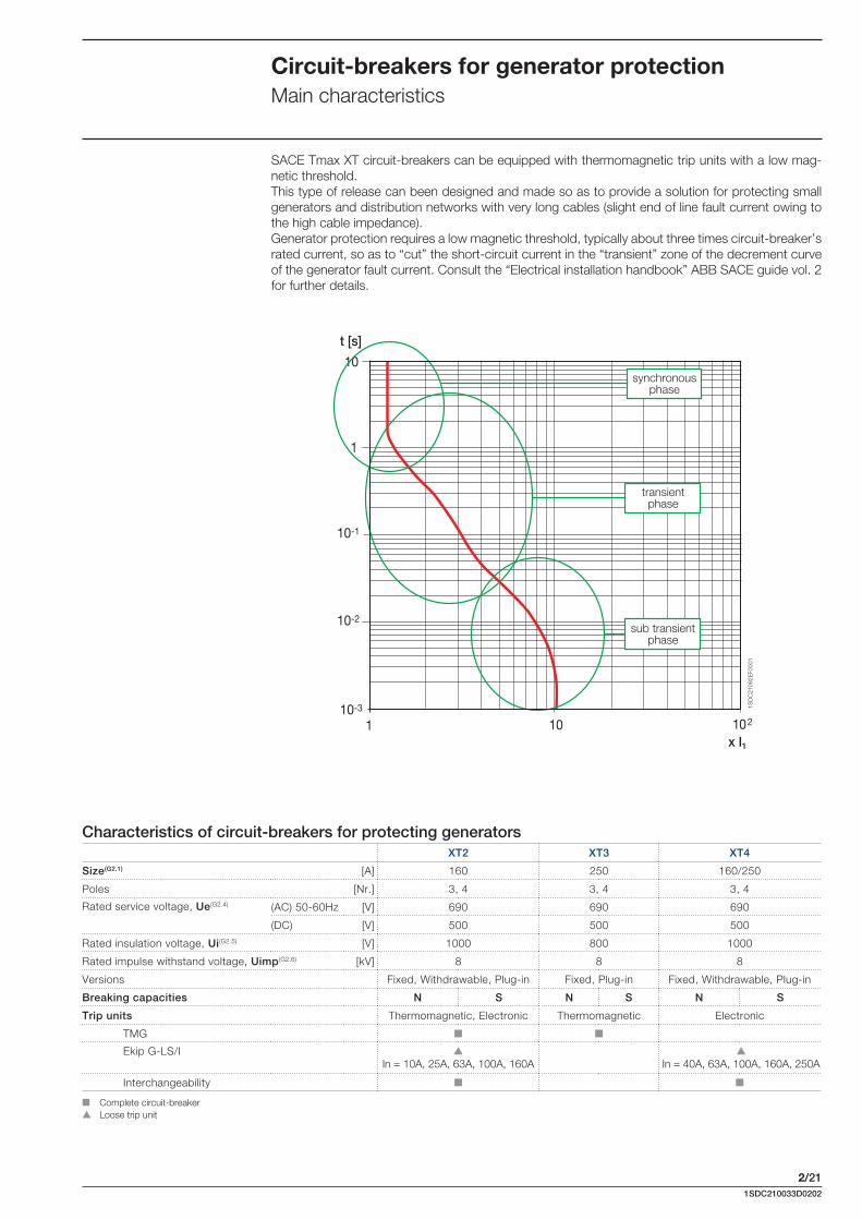
Circuit-breakers for generator protectionMain characteristics
SACE Tmax XT circuit-breakers can be equipped with thermomagnetic trip units with a low mag-netic threshold.This type of release can been designed and made so as to provide a solution for protecting small generators and distribution networks with very long cables (slight end of line fault current owing to the high cable impedance). Generator protection requires a low magnetic threshold, typically about three times circuit-breaker’s rated current, so as to “cut” the short-circuit current in the “transient” zone of the decrement curve of the generator fault current. Consult the “Electrical installation handbook” ABB SACE guide vol. 2 for further details.
Characteristics of circuit-breakers for protecting generatorsXT2 XT3 XT4
Size(G2.1) [A] 160 250 160/250
Poles [Nr.] 3, 4 3, 4 3, 4
Rated service voltage, Ue(G2.4) (AC) 50-60Hz [V] 690 690 690
(DC) [V] 500 500 500
Rated insulation voltage, Ui(G2.5) [V] 1000 800 1000
Rated impulse withstand voltage, Uimp(G2.6) [kV] 8 8 8
Versions Fixed, Withdrawable, Plug-in Fixed, Plug-in Fixed, Withdrawable, Plug-in
Breaking capacities N S N S N S
Trip units Thermomagnetic, Electronic Thermomagnetic Electronic
TMG
Ekip G-LS/IIn = 10A, 25A, 63A, 100A, 160A In = 40A, 63A, 100A, 160A, 250A
Interchangeability
Complete circuit-breaker Loose trip unit
synchronous phase
transient phase
sub transient phase

2/221SDC210033D0202
TMG
Main characteristics:
available for XT2 and XT3 in the three-pole and four-pole versions;
protections: – against overloads (L): adjustable 0.7...1xIn protection threshold, with inverse long-time trip
curve;– against instantaneous short-circuits (I): fi xed 3xIn protection threshold, with instantaneous
trip curve;– 100% neutral protection in four-pole circuit-breakers;
the thermal protection setting is made by turning the relative cursor on the front of the release.
XT2 TMG
In [A] 16(1) 20(1) 25(1) 32(1) 40(1) 50(1) 63(1) 80 100 125 160
Neutral [A] - 100% 16 20 25 32 40 50 63 80 100 125 160
I1 = 0.7…1xIn
I3 [A] 160 160 160 160 200 200 200 240 300 375 480
Neutral [A] - 100% 160 160 160 160 200 200 200 240 300 375 480
I3 = 3xIn
(1) Available only as complete circuit-breaker
XT3TMG
In [A] 63 80 100 125 160 200 250
Neutral [A] - 100% 63 80 100 125 160 200 250
I1 = 0.7…1xIn
I3 [A] 400 400 400 400 480 600 750
Neutral [A] - 100% 400 400 400 400 480 600 750
I3 = 3xIn
Rotary switch for thermal protection setting
Example with XT3 250A
Circuit-breakers for generator protectionMain characteristics
2/231SDC210033D0202
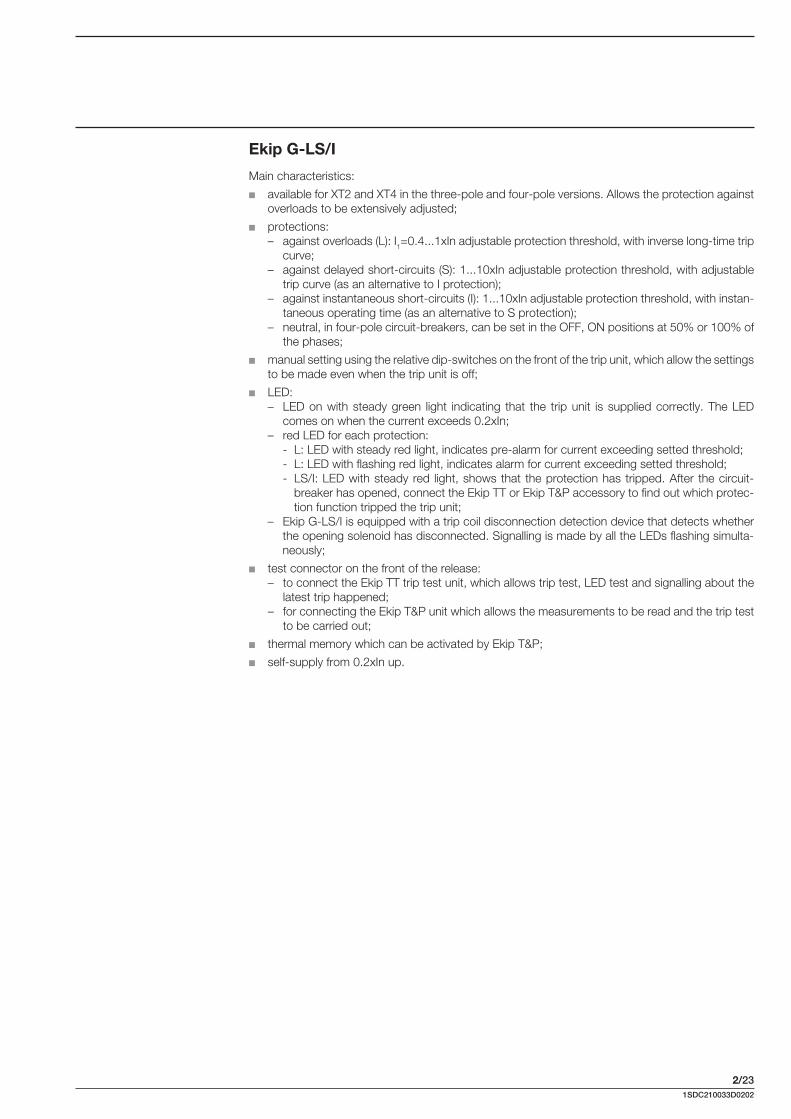
Ekip G-LS/I
Main characteristics:
available for XT2 and XT4 in the three-pole and four-pole versions. Allows the protection against overloads to be extensively adjusted;
protections: – against overloads (L): I1=0.4...1xIn adjustable protection threshold, with inverse long-time trip
curve;– against delayed short-circuits (S): 1...10xIn adjustable protection threshold, with adjustable
trip curve (as an alternative to I protection);– against instantaneous short-circuits (I): 1...10xIn adjustable protection threshold, with instan-
taneous operating time (as an alternative to S protection);– neutral, in four-pole circuit-breakers, can be set in the OFF, ON positions at 50% or 100% of
the phases;
manual setting using the relative dip-switches on the front of the trip unit, which allow the settings to be made even when the trip unit is off;
LED: – LED on with steady green light indicating that the trip unit is supplied correctly. The LED
comes on when the current exceeds 0.2xIn;– red LED for each protection:
- L: LED with steady red light, indicates pre-alarm for current exceeding setted threshold;- L: LED with flashing red light, indicates alarm for current exceeding setted threshold;- LS/I: LED with steady red light, shows that the protection has tripped. After the circuit-
breaker has opened, connect the Ekip TT or Ekip T&P accessory to find out which protec-tion function tripped the trip unit;
– Ekip G-LS/I is equipped with a trip coil disconnection detection device that detects whether the opening solenoid has disconnected. Signalling is made by all the LEDs flashing simulta-neously;
test connector on the front of the release:– to connect the Ekip TT trip test unit, which allows trip test, LED test and signalling about the
latest trip happened;– for connecting the Ekip T&P unit which allows the measurements to be read and the trip test
to be carried out;
thermal memory which can be activated by Ekip T&P;
self-supply from 0.2xIn up.
2/241SDC210033D0202
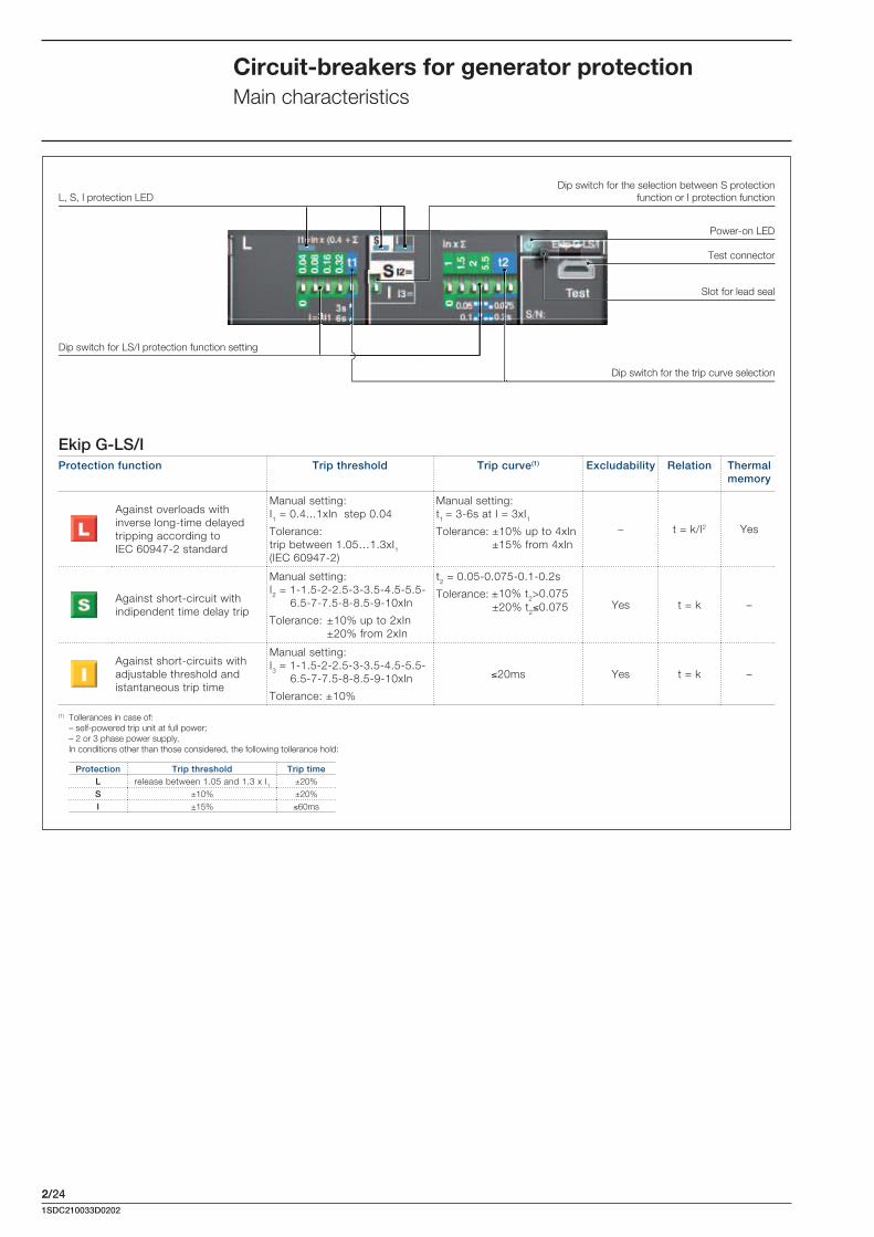
Ekip G-LS/IProtection function Trip threshold Trip curve(1) Excludability Relation Thermal
memory
Against overloads with inverse long-time delayed tripping according to IEC 60947-2 standard
Manual setting:I1 = 0.4...1xIn step 0.04
Tolerance:trip between 1.05…1.3xI1(IEC 60947-2)
Manual setting:t1 = 3-6s at I = 3xI1Tolerance: ±10% up to 4xIn ±15% from 4xIn
– t = k/l2 Yes
Against short-circuit with indipendent time delay trip
Manual setting:I2 = 1-1.5-2-2.5-3-3.5-4.5-5.5-
6.5-7-7.5-8-8.5-9-10xIn
Tolerance: ±10% up to 2xIn ±20% from 2xIn
t2 = 0.05-0.075-0.1-0.2s
Tolerance: ±20% t2 0.075 Yes t = k –
Against short-circuits with adjustable threshold and istantaneous trip time
Manual setting:I3 = 1-1.5-2-2.5-3-3.5-4.5-5.5-
6.5-7-7.5-8-8.5-9-10xIn
Tolerance: ±10%
20ms Yes t = k –
Test connector
Power-on LED
L, S, I protection LED
Dip switch for the trip curve selection
Dip switch for LS/I protection function setting
Dip switch for the selection between S protection function or I protection function
(1) Tollerances in case of: – self-powered trip unit at full power; – 2 or 3 phase power supply. In conditions other than those considered, the following tollerance hold:
Protection Trip threshold Trip timeL release between 1.05 and 1.3 x I1 ±20%S ±10% ±20%I ±15% 60ms
Slot for lead seal
Circuit-breakers for generator protectionMain characteristics
±10% t2>0.075

2/251SDC210033D0202
Circuit-breakers for oversized neutral protectionMain characteristics
The SACE Tmax XT range of circuit-breakers with oversized neutral is used in certain applications where harmonics or unbalance loads or single phase create an overload on the neutral conductor. Under these conditions, a current of a considerable value could travel along the neutral conductor. In particular, third-order harmonics and relative multiples add together on the neutral and give rise to a current value that could be higher than the one which travels along the phase conductors.For this reason, circuit-breakers with oversized neutral provide adequate protection in installations where the neutral conductor is sized with a larger section than the phase conductors.The main types of equipment that generate harmonics are given below by way of example: personal computers; fluorescent lamps; static converters; no-break power units; variable speed drives; welding machines.
By and large, the wave shape is distorted owing to the presence of semiconductor devices able to conduct for a fraction of the entire cycle, creating discontinuous trends and consequently introduc-ing numerous harmonics.Consult the “Electrical installation handbook” ABB SACE guide vol. 2 for further details.
Characteristics of circuit-breakers for oversized neutral protectionXT2 XT4
Size(G2.1) [A] 160 160/250
Uninterrupted nominal current, In [A] 10, 63, 100 40, 63, 100, 160
Poles [Nr.] 4 4
Rated service voltage, Ue(G2.4) (AC) 50-60Hz [V] 690 690
Rated insulation voltage, Ui(G2.5) [V] 1000 1000
Rated impulse withstand voltage, Uimp(G2.6) [kV] 8 8
Versions Fixed, Withdrawable, Plug-in Fixed, Withdrawable, Plug-in
Breaking capacity N S H L V N S H L V
Trip units Electronic Electronic
Ekip N-LS/I
Interchangeability
Complete circuit-breaker Loose trip unit

2/261SDC210033D0202
Ekip N-LS/IProtection function
Trip threshold Time-current curve(1) Excludability Relation Thermal memory
Against overloads with inverse long-time delayed tripping. According to IEC 60947-2 Standard
Manual setting:I1 = 0.4...1xIn step 0.04
Tolerance: trip between 1.05…1.3xI1 (IEC 60947-2)
Manual setting:t1 = 12-36s at I= 3xI1Tolerance: ±10% up to 4xIn ±15% from 4xIn
– t = k/l2 Yes
Against short-circuits with inverse short indipendent time delay trip (t=k)
Manual setting:I2 = 1-1.5-2-2.5-3-3.5-4.5-5.5-
6.5-7-7.5-8-8.5-9-10xIn
Tolerance: ±10%
t2 = 0.1-0.2s
Tolerance: ±15% Yes t = k –
Against short-circuits with istantaneous trip time
Manual setting:I3 = 1-1.5-2-2.5-3-3.5-4.5-5.5-
6.5-7-7.5-8-8.5-9-10xIn
Tolerance: ±10%
20ms Yes t = k –
Test connector
Power-on LED
L, S, I protection LED
Dip switch for the trip curve selectionDip switch for LS/I protection function setting
Dip switch for the selection between S protection function or I protection function
Dip switch for neutral selection
(1) Tollerances in case of: – self-powered trip unit at full power; – 2 or 3 phase power supply. In conditions other than those considered, the following tollerance hold:
Protection Trip threshold Trip timeL release between 1.05 and 1.3 x I1 ±20%S ±10% ±20%I ±15% 60ms
Ekip N-LS/I Main characteristics: available for XT2 and XT4 in the four-pole version; protections:
– against overload (L): I1=0.4...1xIn adjustable protection threshold, with inverse long-time trip curve;
– against delayed short-circuits (S): 1...10xIn adjustable protection threshold, with adjustable trip curve (as an alternative to I protection);
– against instantaneous short-circuit (I): 1...10xIn adjustable protection threshold, with instan-taneous operating time (as an alternative to S protection);
– neutral can be set in the OFF or ON positions, at 100% or at 160% of the phases;
manual setting using the relative dip-switches on the front of the trip unit, which allow the set-tings to be made even when the trip unit is off;
LED: – LED on with steady green light indicating that the trip unit is supplied correctly. The LED
comes on when the current exceeds 0.32xIn;– red LED for each protection:
- L: LED with steady red light, indicates pre-alarm for current exceeding 0.9xI1;- L: LED with fl ashing red light, indicates alarm for current exceeding setted threshold;- LS/I: LED with steady red light, shows that the protection has tripped. After the circuit-
breaker has opened, connect the Ekip TT or Ekip T&P accessory to fi nd out which protec-tion function tripped the trip unit;
– Ekip N-LS/I is equipped with a device that detects whether the opening solenoid has discon-nected. Signalling is made by all the LEDs fl ashing simultaneously;
test connector on the front of the release:– to connect the Ekip TT trip test unit which allows trip test, LED test and signalling about the
latest trip happened;– for connecting the Ekip T&P unit, which allows the measurements to be read and the trip test
to be carried out; thermal memory which can be activated by Ekip T&P; self-supply from 0.32xIn.
Slot for lead seal
Circuit-breakers for oversized neutral protectionMain characteristics