Embed Size (px)
Citation preview
New/Additions Industrial, Commercial, Institutional, High-Rise Residential Buildings - Building Permit Application Requirements
***Please note that various Industrial/Commercial/Institutional and high-rise residential lands within the City of Vaughan are subject to Site Plan Control under the Planning Act. The Site Plan Letter of Undertaking or a Site Plan Agreement must be approved and in place prior to the building permit application***
Designer Requirements
All drawings submitted for building-permit application are required to be prepared and reviewed by a qualified designer, architect or professional engineer or a combination thereof.
Drawings prepared by an architect or professional engineer, as required, must be sealed, signed and dated.
The Building Code requires qualified and registered designers who review and take responsibility for design activities to include the following information on any documents submitted to a chief building official or registered code agency:
• The name and building code identification number (BCIN) of the registered firm. • A statement that the qualified person has reviewed and taken responsibility for the
design activities. • The name and BCIN of the qualified person. • The signature of the qualified person
Drawing Requirements
Two sets of construction drawings including:
• Site plan (As approved under City’s Site Plan Control process.) • Key plan • Architectural drawings (Elevations must be as approved under City’s Site Plan Control
process.) • Structural drawings • Heating, ventilation and air conditioning drawings and calculations • Plumbing drawings, and calculations • Electrical drawings • Sprinkler system drawings complete with hydraulic calculations and Water Demand
Curve (if applicable) • Fire alarm system drawings (if applicable) • Specifications (if applicable) • On-site sewage system design (if applicable) • Site Servicing Drawings (if applicable)
1
All drawings shall be fully dimensioned, drawn at minimum scale of 1:75 or 3/16"= 1'-0"
Drawings for additions must differentiate between the existing building and new work being proposed.
Additional Information Required for Application
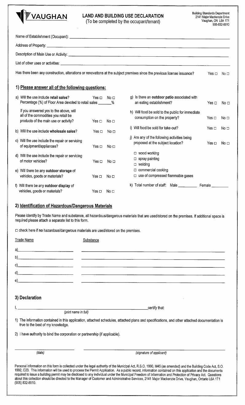
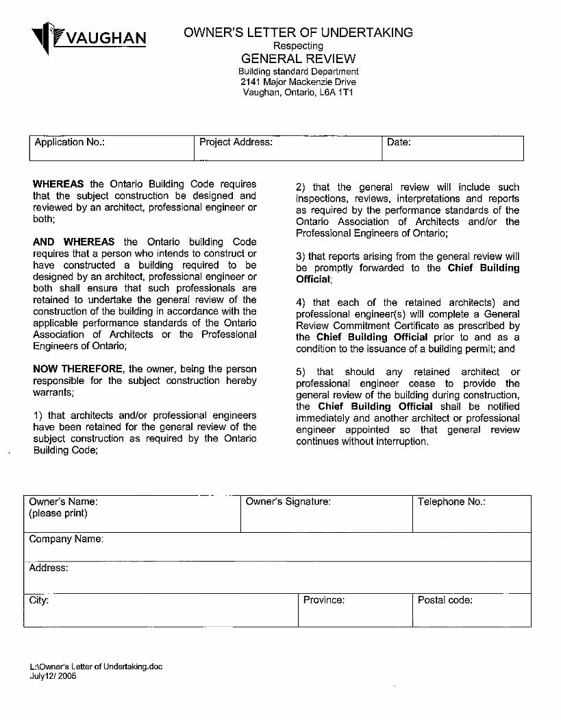
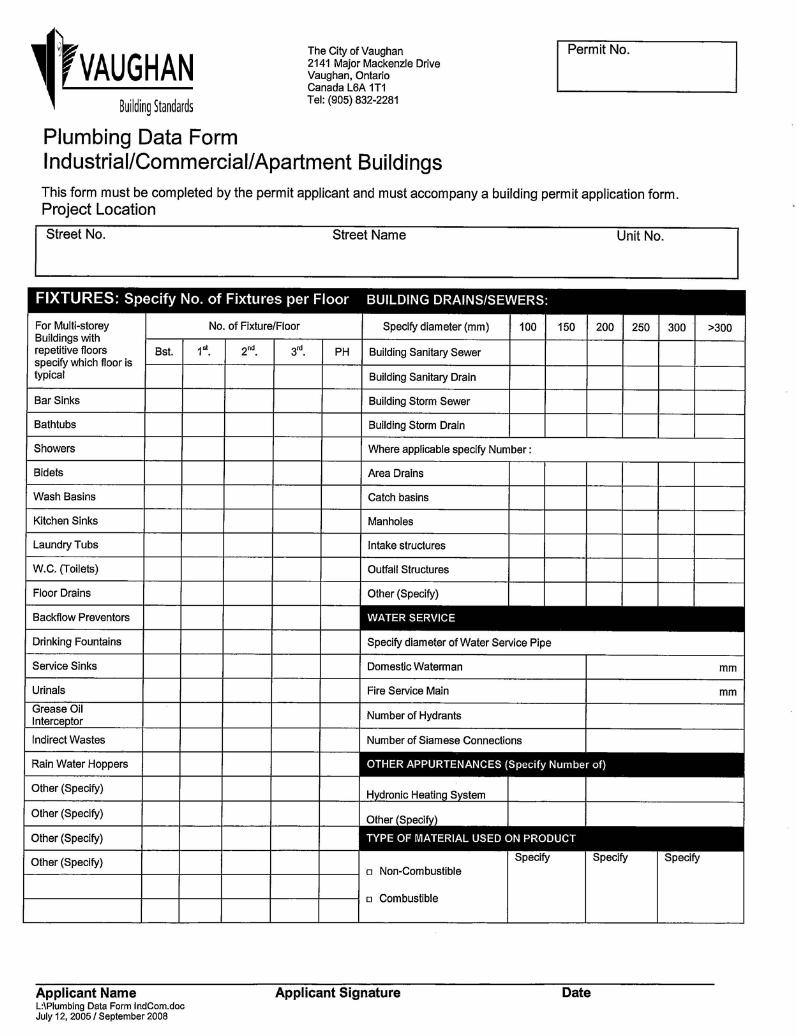
• Application for a Permit to Construct or Demolish • Schedule 1 Designer Information Form • Land & Building Use Declaration Form • Owner’s Letter of Undertaking Respecting General Review Form • General Review Commitment Form • Non-Housing Plumbing Data Sheet • Statement of Design Form and/or the Ont. Assoc. of Architects Building Code Data
Matrix • SB-10 Compliance Requirements • Site Plan Letter of Undertaking or Site Plan Agreement (if applicable) • York Regional Health Approval (if applicable) • Ministry of Health Approval (if applicable) • Alternative solution proposal (if applicable) • Tarion warranty program registration number (Residential Condominium Buildings) • Any other documents that pertain to your project
Fees
Building permit fees and building permit securities are payable at the time of application and are as follows: Building Permit Fees See Schedule “A” Classes of Permits and Fees, City of
Vaughan By-law number 044-2015 Refundable Permit Securities: See Building Permit Securities Information Form
Development Charges are payable at time of issuance and are determined during the building permit review process. Applicant will be informed of these fees prior to building permit issuance.
Permit Processing and Turn-Around Time Once a complete permit application is made it will be reviewed by a Zoning Examiner Architectural/Structural Plans Examiner, Mechanical Plans Examiner and the Vaughan Fire Department for compliance with the Building Code and other applicable law. The applicant will be advised by the Applications Expediter of any examination deficiencies.
2

Building permit review times are dependant upon permit volumes. An application is considered “complete” if all required forms, documents and applicable information have been submitted and all permit fees and have been paid. If an application is “complete”, the City of Vaughan endeavours to issue the permit or advise applicants of all application examination deficiencies within 15 – 20 business days (time is dependent on building size and classification) from the date of the application.
Applications that do not have all the required forms, documents and applicable information are considered “incomplete” and are not subject to timeline specified above. Where to Apply To apply for a building permit please bring all required documents to the Building Standards Department on the 1st floor at City Hall. City Hall is located at 2141 Major Mackenzie Drive, Vaughan, Ontario.
Office Hours
Monday to Friday 8:30am – 4:30pm Questions?
Phone: 905-832-8510
3
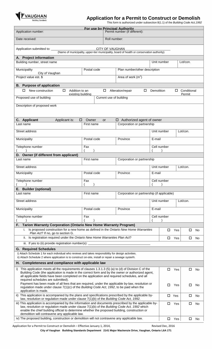
Application for a Permit to Construct or Demolish
This form is authorized under subsection 8(1.1) of the Building Code Act,1992
For use by Principal Authority Application number: Permit number (if different):
Date received: Roll number:
Application submitted to: CITY OF VAUGHAN
(Name of municipality, upper-tier municipality, board of health or conservation authority)
A. Project information Building number, street name Unit number Lot/con.
Municipality City of Vaughan
Postal code Plan number/other description
Project value est. $ Area of work (m2)
B. Purpose of application New construction Addition to an Alteration/repair Demolition Conditional
existing building Permit Proposed use of building Current use of building
Description of proposed work C. Applicant Applicant is: Owner or Authorized agent of owner Last name First name Corporation or partnership
Street address Unit number Lot/con.
Municipality Postal code Province E-mail
Telephone number ( )
Fax ( )
Cell number ( )
D. Owner (if different from applicant) Last name First name Corporation or partnership
Street address Unit number Lot/con.
Municipality Postal code Province E-mail
Telephone number ( )
Fax ( )
Cell number ( )
E. Builder (optional) Last name First name Corporation or partnership (if applicable)
Street address Unit number Lot/con.
Municipality Postal code Province E-mail
Telephone number ( )
Fax ( )
Cell number ( )
F. Tarion Warranty Corporation (Ontario New Home Warranty Program) i. Is proposed construction for a new home as defined in the Ontario New Home Warranties
Plan Act? If no, go to section G. Yes No
ii. Is registration required under the Ontario New Home Warranties Plan Act? Yes No
iii. If yes to (ii) provide registration number(s):
G. Required Schedules i) Attach Schedule 1 for each individual who reviews and takes responsibility for design activities. ii) Attach Schedule 2 where application is to construct on-site, install or repair a sewage system.
H. Completeness and compliance with applicable law i) This application meets all the requirements of clauses 1.3.1.3 (5) (a) to (d) of Division C of the
Building Code (the application is made in the correct form and by the owner or authorized agent, all applicable fields have been completed on the application and required schedules, and all required schedules are submitted). Payment has been made of all fees that are required, under the applicable by-law, resolution or regulation made under clause 7(1)(c) of the Building Code Act, 1992, to be paid when the application is made.
Yes
Yes
No
No
ii) This application is accompanied by the plans and specifications prescribed by the applicable by-law, resolution or regulation made under clause 7(1)(b) of the Building Code Act, 1992.
Yes No
iii) This application is accompanied by the information and documents prescribed by the applicable by- law, resolution or regulation made under clause 7(1)(b) of the Building Code Act, 1992 which enable the chief building official to determine whether the proposed building, construction or demolition will contravene any applicable law.
Yes No
iv) The proposed building, construction or demolition will not contravene any applicable law.
Yes No
Application for a Permit to Construct or Demolish – Effective January 1, 2014, Revised Dec, 2016
City of Vaughan Building Standards Department 2141 Major Mackenzie Drive, Vaughan, Ontario L6A 1T1
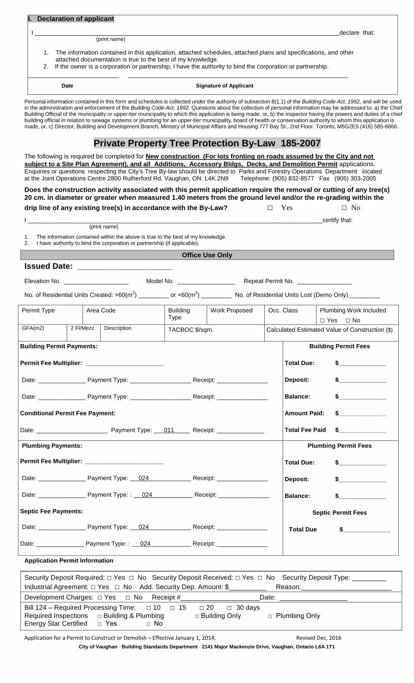
I. Declaration of applicant
I declare that: (print name)
1. The information contained in this application, attached schedules, attached plans and specifications, and other attached documentation is true to the best of my knowledge.
2. If the owner is a corporation or partnership, I have the authority to bind the corporation or partnership.
Date Signature of Applicant
Personal information contained in this form and schedules is collected under the authority of subsection 8(1.1) of the Building Code Act, 1992, and will be used in the administration and enforcement of the Building Code Act, 1992. Questions about the collection of personal information may be addressed to: a) the Chief Building Official of the municipality or upper-tier municipality to which this application is being made, or, b) the inspector having the powers and duties of a chief building official in relation to sewage systems or plumbing for an upper-tier municipality, board of health or conservation authority to whom this application is made, or, c) Director, Building and Development Branch, Ministry of Municipal Affairs and Housing 777 Bay St., 2nd Floor. Toronto, M5G2E5 (416) 585-6666.
Private Property Tree Protection By-Law 185-2007 The following is required be completed for New construction (For lots fronting on roads assumed by the City and not subject to a Site Plan Agreement), and all Additions, Accessory Bldgs, Decks, and Demolition Permit applications. Enquiries or questions respecting the City’s Tree By-law should be directed to Parks and Forestry Operations Department located at the Joint Operations Centre 2800 Rutherford Rd. Vaughan, ON. L4K 2N9 Telephone: (905) 832-8577 Fax (905) 303-2005
Does the construction activity associated with this permit application require the removal or cutting of any tree(s) 20 cm. in diameter or greater when measured 1.40 meters from the ground level and/or the re-grading within the drip line of any existing tree(s) in accordance with the By-Law? □ Yes □ No I _______________________________________________________________________________________certify that: (print name)
1. The information contained within the above is true to the best of my knowledge. 2. I have authority to bind the corporation or partnership (if applicable).
Office Use Only Issued Date: _____________________
Elevation No. ___________________ Model No. _________________ Repeat Permit No. ________________
No. of Residential Units Created: ˃60(m2) _________ or ˂60(m2) _________ No. of Residential Units Lost (Demo Only) _________
Permit Type Area Code Building Type
Work Proposed Occ. Class Plumbing Work Included □ Yes □ No
GFA(m2) 2 Fl/Mezz Description TACBOC $/sqm. Calculated Estimated Value of Construction ($)
Building Permit Payments: Permit Fee Multiplier: _______________________ Date: ______________ Payment Type: __________________ Receipt: _______________ Date: ______________ Payment Type: __________________ Receipt: _______________
Conditional Permit Fee Payment: Date: _____________________ Payment Type: 011 Receipt: ______________
Building Permit Fees Total Due: $______________ Deposit: $______________ Balance: $______________ Amount Paid: $______________ Total Fee Paid $______________
Plumbing Payments: Permit Fee Multiplier: _______________________ Date: ______________ Payment Type: 024 Receipt: _______________ Date: ______________ Payment Type: : 024 Receipt: _______________
Septic Fee Payments: Date: ______________ Payment Type: 024 Receipt: _______________
Date: ______________ Payment Type: : 024 Receipt: _______________
Plumbing Permit Fees Total Due: $______________ Deposit: $______________ Balance: $______________
Septic Permit Fees
Total Due $______________
Application Permit Information
Security Deposit Required: □ Yes □ No Security Deposit Received: □ Yes □ No Security Deposit Type: _________ Industrial Agreement: □ Yes □ No Add. Security Dep. Amount: $__________ Reason:________________________ Development Charges: □ Yes □ No Receipt #_____________________Date: __________________ Bill 124 – Required Processing Time: □ 10 □ 15 □ 20 □ 30 days Required Inspections □ Building & Plumbing □ Building Only □ Plumbing Only Energy Star Certified □ Yes □ No
Application for a Permit to Construct or Demolish – Effective January 1, 2014, Revised Dec, 2016
City of Vaughan Building Standards Department 2141 Major Mackenzie Drive, Vaughan, Ontario L6A 1T1
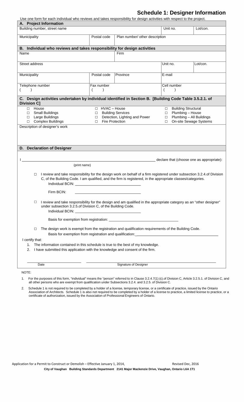
Schedule 1: Designer Information Use one form for each individual who reviews and takes responsibility for design activities with respect to the project. A. Project Information Building number, street name Unit no. Lot/con.
Municipality Postal code Plan number/ other description
B. Individual who reviews and takes responsibility for design activities Name Firm
Street address Unit no. Lot/con.
Municipality Postal code Province E-mail
Telephone number ( )
Fax number ( )
Cell number ( )
C. Design activities undertaken by individual identified in Section B. [Building Code Table 3.5.2.1. of Division C]
□ House □ HVAC – House □ Building Structural □ Small Buildings □ Building Services □ Plumbing – House □ Large Buildings □ Detection, Lighting and Power □ Plumbing – All Buildings □ Complex Buildings □ Fire Protection □ On-site Sewage Systems
Description of designer’s work
D. Declaration of Designer
I declare that (choose one as appropriate):
(print name)
□ I review and take responsibility for the design work on behalf of a firm registered under subsection 3.2.4.of Division C, of the Building Code. I am qualified, and the firm is registered, in the appropriate classes/categories.
Individual BCIN:
Firm BCIN:
□ I review and take responsibility for the design and am qualified in the appropriate category as an “other designer” under subsection 3.2.5.of Division C, of the Building Code.
Individual BCIN:
Basis for exemption from registration:
□ The design work is exempt from the registration and qualification requirements of the Building Code. Basis for exemption from registration and qualification:_
I certify that: 1. The information contained in this schedule is true to the best of my knowledge. 2. I have submitted this application with the knowledge and consent of the firm.
Date Signature of Designer
NOTE:
1. For the purposes of this form, “individual” means the “person” referred to in Clause 3.2.4.7(1) (c).of Division C, Article 3.2.5.1. of Division C, and all other persons who are exempt from qualification under Subsections 3.2.4. and 3.2.5. of Division C.
2. Schedule 1 is not required to be completed by a holder of a license, temporary license, or a certificate of practice, issued by the Ontario
Association of Architects. Schedule 1 is also not required to be completed by a holder of a license to practice, a limited license to practice, or a certificate of authorization, issued by the Association of Professional Engineers of Ontario.
Application for a Permit to Construct or Demolish – Effective January 1, 2014, Revised Dec, 2016
City of Vaughan Building Standards Department 2141 Major Mackenzie Drive, Vaughan, Ontario L6A 1T1
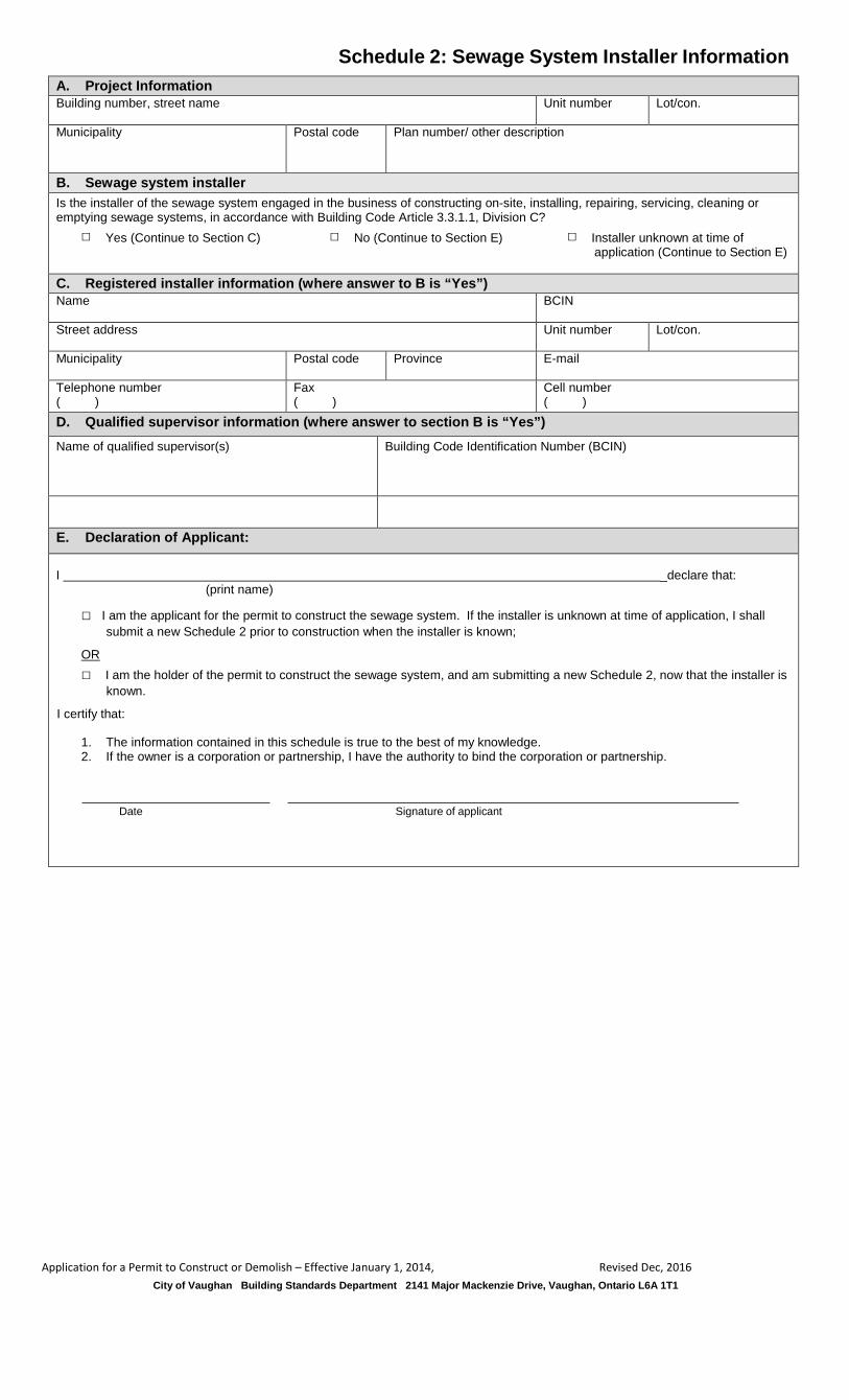
Schedule 2: Sewage System Installer Information
A. Project Information Building number, street name Unit number Lot/con.
Municipality Postal code Plan number/ other description
B. Sewage system installer Is the installer of the sewage system engaged in the business of constructing on-site, installing, repairing, servicing, cleaning or emptying sewage systems, in accordance with Building Code Article 3.3.1.1, Division C?
□ Yes (Continue to Section C) □ No (Continue to Section E) □ Installer unknown at time of application (Continue to Section E)
C. Registered installer information (where answer to B is “Yes”) Name BCIN
Street address Unit number Lot/con.
Municipality Postal code Province E-mail
Telephone number ( )
Fax ( )
Cell number ( )
D. Qualified supervisor information (where answer to section B is “Yes”) Name of qualified supervisor(s) Building Code Identification Number (BCIN)
E. Declaration of Applicant:
I _declare that: (print name)
□ I am the applicant for the permit to construct the sewage system. If the installer is unknown at time of application, I shall submit a new Schedule 2 prior to construction when the installer is known;
OR □ I am the holder of the permit to construct the sewage system, and am submitting a new Schedule 2, now that the installer is
known.
I certify that:
1. The information contained in this schedule is true to the best of my knowledge. 2. If the owner is a corporation or partnership, I have the authority to bind the corporation or partnership.
Date Signature of applicant
Application for a Permit to Construct or Demolish – Effective January 1, 2014, Revised Dec, 2016
City of Vaughan Building Standards Department 2141 Major Mackenzie Drive, Vaughan, Ontario L6A 1T1
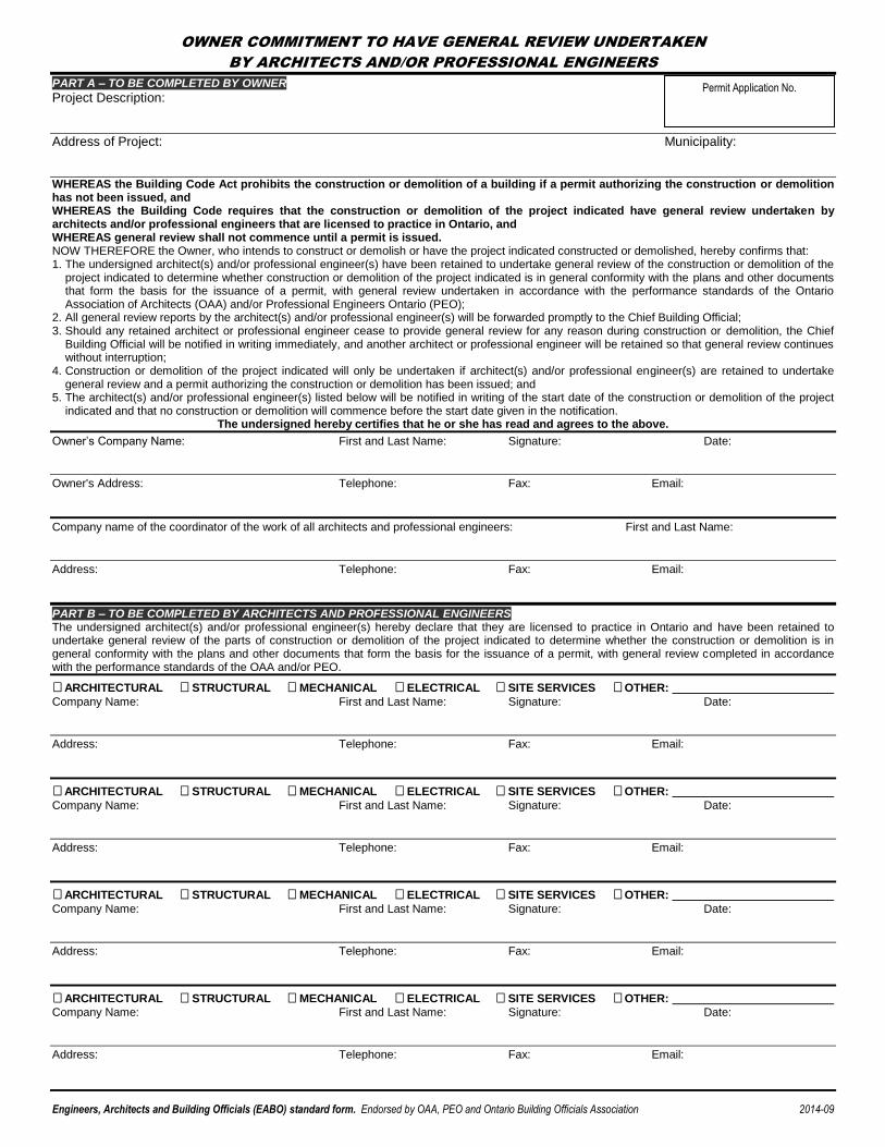
OWNER COMMITMENT TO HAVE GENERAL REVIEW UNDERTAKEN
BY ARCHITECTS AND/OR PROFESSIONAL ENGINEERS
Engineers, Architects and Building Officials (EABO) standard form. Endorsed by OAA, PEO and Ontario Building Officials Association 2014-09
PART A – TO BE COMPLETED BY OWNER
Project Description:
Address of Project: Municipality:
WHEREAS the Building Code Act prohibits the construction or demolition of a building if a permit authorizing the construction or demolition has not been issued, and WHEREAS the Building Code requires that the construction or demolition of the project indicated have general review undertaken by architects and/or professional engineers that are licensed to practice in Ontario, and WHEREAS general review shall not commence until a permit is issued. NOW THEREFORE the Owner, who intends to construct or demolish or have the project indicated constructed or demolished, hereby confirms that: 1. The undersigned architect(s) and/or professional engineer(s) have been retained to undertake general review of the construction or demolition of the
project indicated to determine whether construction or demolition of the project indicated is in general conformity with the plans and other documents that form the basis for the issuance of a permit, with general review undertaken in accordance with the performance standards of the Ontario Association of Architects (OAA) and/or Professional Engineers Ontario (PEO);
2. All general review reports by the architect(s) and/or professional engineer(s) will be forwarded promptly to the Chief Building Official; 3. Should any retained architect or professional engineer cease to provide general review for any reason during construction or demolition, the Chief
Building Official will be notified in writing immediately, and another architect or professional engineer will be retained so that general review continues without interruption;
4. Construction or demolition of the project indicated will only be undertaken if architect(s) and/or professional engineer(s) are retained to undertake general review and a permit authorizing the construction or demolition has been issued; and
5. The architect(s) and/or professional engineer(s) listed below will be notified in writing of the start date of the construction or demolition of the project indicated and that no construction or demolition will commence before the start date given in the notification.
The undersigned hereby certifies that he or she has read and agrees to the above.
Owner’s Company Name: First and Last Name: Signature: Date:
Owner's Address: Telephone: Fax: Email:
Company name of the coordinator of the work of all architects and professional engineers: First and Last Name:
Address: Telephone: Fax: Email:
PART B – TO BE COMPLETED BY ARCHITECTS AND PROFESSIONAL ENGINEERS The undersigned architect(s) and/or professional engineer(s) hereby declare that they are licensed to practice in Ontario and have been retained to undertake general review of the parts of construction or demolition of the project indicated to determine whether the construction or demolition is in general conformity with the plans and other documents that form the basis for the issuance of a permit, with general review completed in accordance with the performance standards of the OAA and/or PEO.
ARCHITECTURAL STRUCTURAL MECHANICAL ELECTRICAL SITE SERVICES OTHER:
Company Name: First and Last Name: Signature: Date:
Address: Telephone: Fax: Email:
ARCHITECTURAL STRUCTURAL MECHANICAL ELECTRICAL SITE SERVICES OTHER:
Company Name: First and Last Name: Signature: Date:
Address: Telephone: Fax: Email:
ARCHITECTURAL STRUCTURAL MECHANICAL ELECTRICAL SITE SERVICES OTHER:
Company Name: First and Last Name: Signature: Date:
Address: Telephone: Fax: Email:
ARCHITECTURAL STRUCTURAL MECHANICAL ELECTRICAL SITE SERVICES OTHER:
Company Name: First and Last Name: Signature: Date:
Address: Telephone: Fax: Email:
Permit Application No.
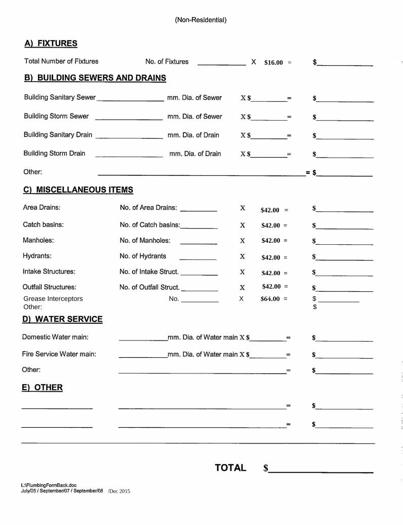
$42.00 =
$42.00 = $42.00 =
$42.00 = $42.00 = $42.00 =
$16.00 =
/Dec 2015
Grease Interceptors No. __________ X $64.00 = $ ___________ Other: $
Building Standards
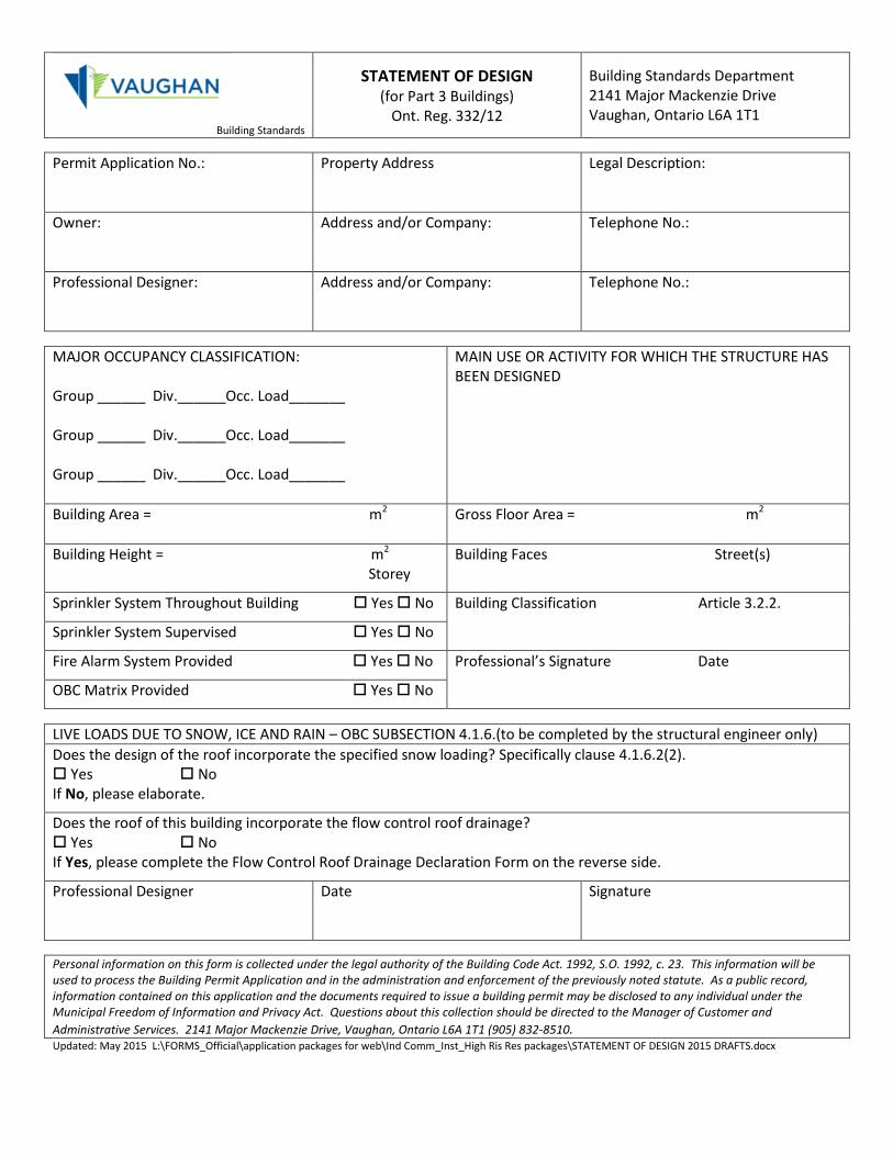
STATEMENT OF DESIGN (for Part 3 Buildings)
Ont. Reg. 332/12
Building Standards Department 2141 Major Mackenzie Drive Vaughan, Ontario L6A 1T1
Permit Application No.:
Property Address Legal Description:
Owner:
Address and/or Company: Telephone No.:
Professional Designer:
Address and/or Company: Telephone No.:
MAJOR OCCUPANCY CLASSIFICATION: Group ______ Div.______Occ. Load_______ Group ______ Div.______Occ. Load_______ Group ______ Div.______Occ. Load_______
MAIN USE OR ACTIVITY FOR WHICH THE STRUCTURE HAS BEEN DESIGNED
Building Area = m2 Gross Floor Area = m2
Building Height = m2 Storey
Building Faces Street(s)
Sprinkler System Throughout Building Yes No Building Classification Article 3.2.2. Sprinkler System Supervised Yes No
Fire Alarm System Provided Yes No Professional’s Signature Date
OBC Matrix Provided Yes No
LIVE LOADS DUE TO SNOW, ICE AND RAIN – OBC SUBSECTION 4.1.6.(to be completed by the structural engineer only) Does the design of the roof incorporate the specified snow loading? Specifically clause 4.1.6.2(2). Yes No If No, please elaborate.
Does the roof of this building incorporate the flow control roof drainage? Yes No If Yes, please complete the Flow Control Roof Drainage Declaration Form on the reverse side.
Professional Designer
Date Signature
Personal information on this form is collected under the legal authority of the Building Code Act. 1992, S.O. 1992, c. 23. This information will be used to process the Building Permit Application and in the administration and enforcement of the previously noted statute. As a public record, information contained on this application and the documents required to issue a building permit may be disclosed to any individual under the Municipal Freedom of Information and Privacy Act. Questions about this collection should be directed to the Manager of Customer and Administrative Services. 2141 Major Mackenzie Drive, Vaughan, Ontario L6A 1T1 (905) 832-8510. Updated: May 2015 L:\FORMS_Official\application packages for web\Ind Comm_Inst_High Ris Res packages\STATEMENT OF DESIGN 2015 DRAFTS.docx
Building Standards
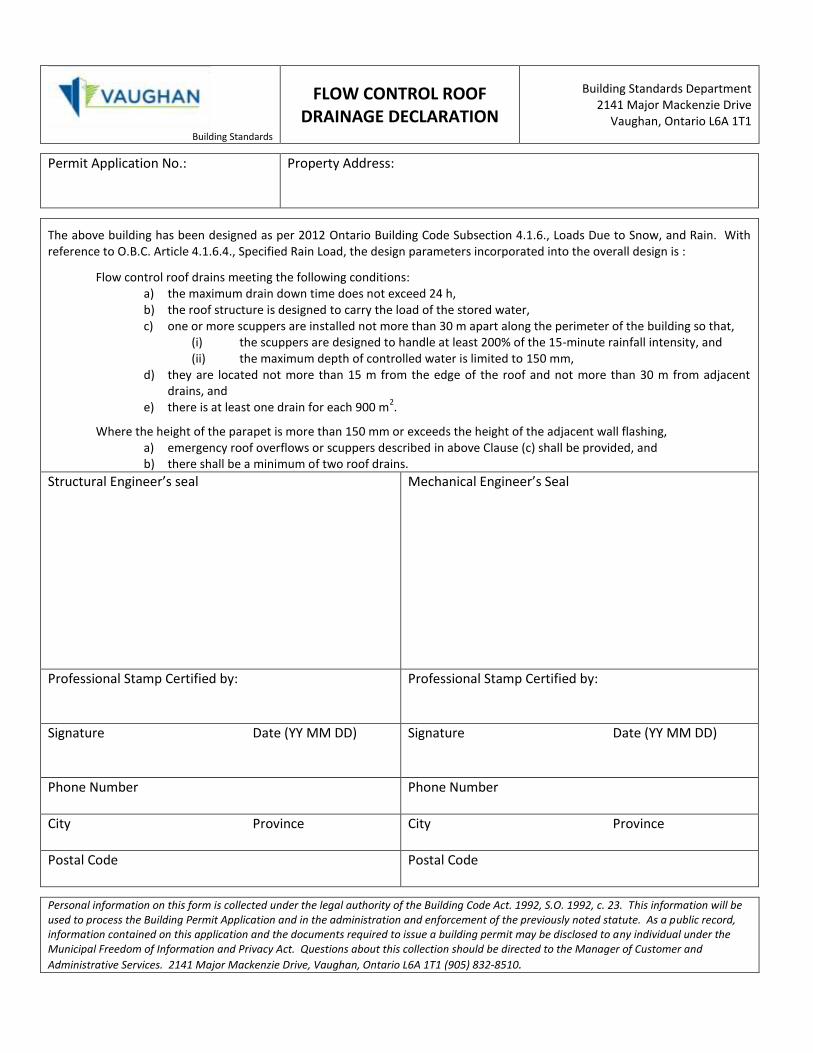
FLOW CONTROL ROOF DRAINAGE DECLARATION
Building Standards Department 2141 Major Mackenzie Drive
Vaughan, Ontario L6A 1T1
Permit Application No.:
Property Address:
The above building has been designed as per 2012 Ontario Building Code Subsection 4.1.6., Loads Due to Snow, and Rain. With reference to O.B.C. Article 4.1.6.4., Specified Rain Load, the design parameters incorporated into the overall design is :
Flow control roof drains meeting the following conditions: a) the maximum drain down time does not exceed 24 h, b) the roof structure is designed to carry the load of the stored water, c) one or more scuppers are installed not more than 30 m apart along the perimeter of the building so that, (i) the scuppers are designed to handle at least 200% of the 15-minute rainfall intensity, and (ii) the maximum depth of controlled water is limited to 150 mm, d) they are located not more than 15 m from the edge of the roof and not more than 30 m from adjacent
drains, and e) there is at least one drain for each 900 m
2.
Where the height of the parapet is more than 150 mm or exceeds the height of the adjacent wall flashing, a) emergency roof overflows or scuppers described in above Clause (c) shall be provided, and b) there shall be a minimum of two roof drains.
Structural Engineer’s seal
Mechanical Engineer’s Seal
Professional Stamp Certified by:
Professional Stamp Certified by:
Signature Date (YY MM DD)
Signature Date (YY MM DD)
Phone Number
Phone Number
City Province
City Province
Postal Code Postal Code
Personal information on this form is collected under the legal authority of the Building Code Act. 1992, S.O. 1992, c. 23. This information will be used to process the Building Permit Application and in the administration and enforcement of the previously noted statute. As a public record, information contained on this application and the documents required to issue a building permit may be disclosed to any individual under the Municipal Freedom of Information and Privacy Act. Questions about this collection should be directed to the Manager of Customer and
Administrative Services. 2141 Major Mackenzie Drive, Vaughan, Ontario L6A 1T1 (905) 832-8510.
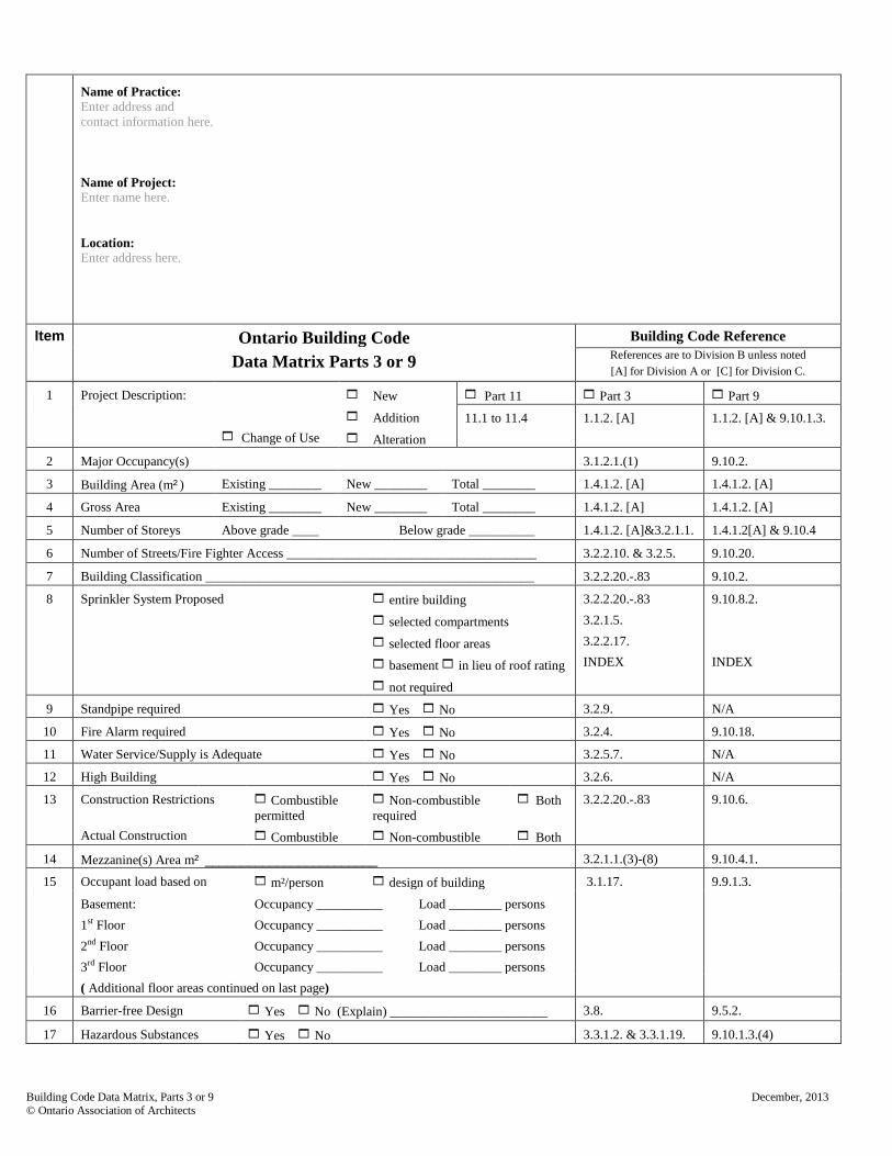
Name of Practice: Enter address and contact information here. Name of Project: Enter name here. Location: Enter address here.
Item Ontario Building Code Building Code Reference
Data Matrix Parts 3 or 9 References are to Division B unless noted [A] for Division A or [C] for Division C.
1 Project Description:
Change of Use
New
Addition
Alteration
Part 11 Part 3 Part 9
11.1 to 11.4 1.1.2. [A] 1.1.2. [A] & 9.10.1.3.
2 Major Occupancy(s) 3.1.2.1.(1) 9.10.2.
3 Building Area (m²) Existing ________ New ________ Total ________ 1.4.1.2. [A] 1.4.1.2. [A]
4 Gross Area Existing ________ New ________ Total ________ 1.4.1.2. [A] 1.4.1.2. [A]
5 Number of Storeys Above grade ____ Below grade __________ 1.4.1.2. [A]&3.2.1.1. 1.4.1.2[A] & 9.10.4
6 Number of Streets/Fire Fighter Access ______________________________________ 3.2.2.10. & 3.2.5. 9.10.20.
7 Building Classification __________________________________________________ 3.2.2.20.-.83 9.10.2.
8 Sprinkler System Proposed entire building
selected compartments
selected floor areas
basement in lieu of roof rating
not required
3.2.2.20.-.83 3.2.1.5. 3.2.2.17. INDEX
9.10.8.2. INDEX
9 Standpipe required Yes No 3.2.9. N/A
10 Fire Alarm required Yes No 3.2.4. 9.10.18.
11 Water Service/Supply is Adequate Yes No 3.2.5.7. N/A
12 High Building Yes No 3.2.6. N/A
13 Construction Restrictions Actual Construction
Combustible permitted
Combustible
Non-combustible required
Non-combustible
Both Both
3.2.2.20.-.83 9.10.6.
14 Mezzanine(s) Area m² ________________________ 3.2.1.1.(3)-(8) 9.10.4.1.
15 Occupant load based on m²/person design of building 3.1.17. 9.9.1.3.
Basement: 1st Floor 2nd Floor 3rd Floor
Occupancy __________ Occupancy __________ Occupancy __________ Occupancy __________
Load ________ persons Load ________ persons Load ________ persons Load ________ persons
( Additional floor areas continued on last page)
16 Barrier-free Design Yes No (Explain) ________________________ 3.8. 9.5.2.
17 Hazardous Substances Yes No 3.3.1.2. & 3.3.1.19. 9.10.1.3.(4)
Building Code Data Matrix, Parts 3 or 9 December, 2013 © Ontario Association of Architects
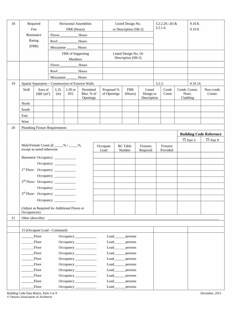
18 Required
Fire Resistance
Rating (FRR)
Horizontal Assemblies FRR (Hours)
Listed Design No. or Description (SB-2)
3.2.2.20.-.83 & 3.2.1.4.
9.10.8. 9.10.9.
Floors __________ Hours
Roof ___________ Hours
Mezzanine ______ Hours
FRR of Supporting Members
Listed Design No. Or Description (SB-2)
Floors __________ Hours
Roof ___________ Hours
Mezzanine ______ Hours
19 Spatial Separation – Construction of Exterior Walls 3.2.3. 9.10.14.
Wall Area of EBF (m²)
L.D. (m)
L/H or H/L
Permitted Max. % of Openings
Proposed % of Openings
FRR (Hours)
Listed Design or
Description
Comb Const
Comb. Constr. Nonc.
Cladding
Non-comb. Constr.
North
South
East
West
20 Plumbing Fixture Requirements
Building Code Reference Part 3 Part 9
Male/Female Count @ _____% / _____%, except as noted otherwise Basement: Occupancy
Occupancy
1st Floor: Occupancy
Occupancy
2nd Floor: Occupancy
Occupancy
3rd Floor: Occupancy
Occupancy (Adjust as Required for Additional Floors or Occupancies)
Occupant Load
BC Table Number
Fixtures Required
Fixtures Provided
21 Other (describe)
15 (Occupant Load - Continued)
_______Floor Occupancy ____________ Load______ persons _______Floor Occupancy ____________ Load______ persons _______Floor Occupancy ____________ Load______ persons _______Floor Occupancy ____________ Load______ persons _______Floor Occupancy ____________ Load______ persons _______Floor Occupancy ____________ Load______ persons _______Floor Occupancy ____________ Load______ persons _______Floor Occupancy ____________ Load______ persons _______Floor Occupancy ____________ Load______ persons _______Floor Occupancy ____________ Load______ persons
Building Code Data Matrix, Parts 3 or 9 December, 2013 © Ontario Association of Architects
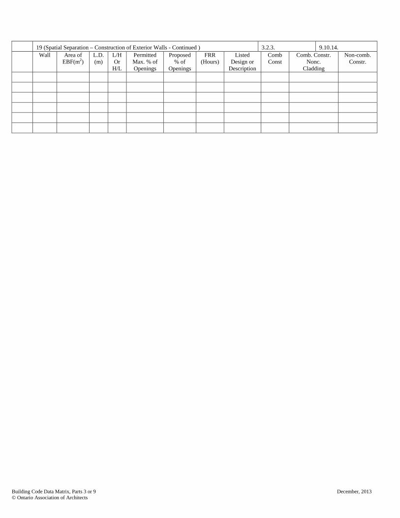
19 (Spatial Separation – Construction of Exterior Walls - Continued ) 3.2.3. 9.10.14.
Wall Area of EBF(m2)
L.D. (m)
L/H Or
H/L
Permitted Max. % of Openings
Proposed % of
Openings
FRR (Hours)
Listed Design or
Description
Comb Const
Comb. Constr. Nonc.
Cladding
Non-comb. Constr.
Building Code Data Matrix, Parts 3 or 9 December, 2013 © Ontario Association of Architects
Name of Practice: Enter address and contact information here. Name of Project: Enter name here. Location: Enter address here. Date:
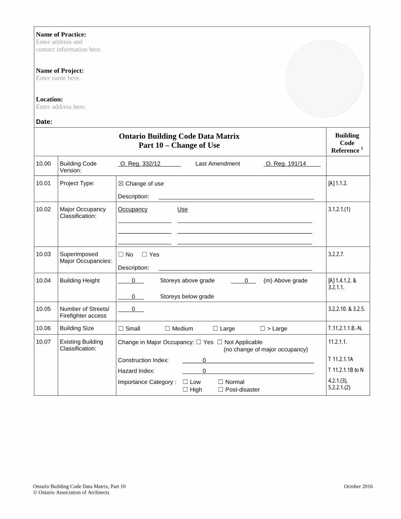
Ontario Building Code Data Matrix Part 10 – Change of Use
Building Code
Reference 1
10.00 Building Code Version:
O. Reg. 332/12 Last Amendment O. Reg. 191/14
10.01 Project Type: ☒ Change of use [A] 1.1.2.
Description:
10.02 Major Occupancy Classification:
Occupancy Use
3.1.2.1.(1)
10.03 Superimposed Major Occupancies:
☐ No ☐ Yes 3.2.2.7.
Description:
10.04 Building Height 0
0
Storeys above grade
Storeys below grade
0 (m) Above grade [A] 1.4.1.2. & 3.2.1.1.
10.05 Number of Streets/ Firefighter access
0 3.2.2.10. & 3.2.5.
10.06 Building Size ☐ Small ☐ Medium ☐ Large ☐ > Large T.11.2.1.1.B.-N.
10.07 Existing Building Classification:
Change in Major Occupancy: ☐ Yes ☐ Not Applicable (no change of major occupancy)
Construction Index: 0
Hazard Index: 0
Importance Category : ☐ Low ☐ Normal ☐ High ☐ Post-disaster
11.2.1.1.
T 11.2.1.1A
T 11.2.1.1B to N
4.2.1.(3), 5.2.2.1.(2)
Ontario Building Code Data Matrix, Part 10 October 2016 © Ontario Association of Architects
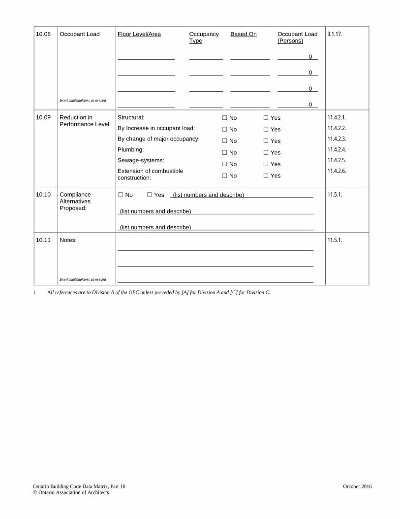
10.08 Occupant Load Insert additional lines as needed
Floor Level/Area
Occupancy Type
Based On
Occupant Load (Persons)
0
0
0
0
3.1.17.
10.09 Reduction in Performance Level:
Structural:
By Increase in occupant load:
By change of major occupancy:
Plumbing:
Sewage-systems:
Extension of combustible construction:
☐ No
☐ No
☐ No
☐ No
☐ No
☐ No
☐ Yes
☐ Yes
☐ Yes
☐ Yes
☐ Yes
☐ Yes
11.4.2.1.
11.4.2.2.
11.4.2.3.
11.4.2.4.
11.4.2.5.
11.4.2.6.
10.10 Compliance Alternatives Proposed:
☐ No ☐ Yes (list numbers and describe)
(list numbers and describe)
(list numbers and describe)
11.5.1.
10.11 Notes: Insert additional lines as needed
11.5.1.
1 All references are to Division B of the OBC unless preceded by [A] for Division A and [C] for Division C.
Ontario Building Code Data Matrix, Part 10 October 2016 © Ontario Association of Architects
Name of Practice: Enter address and contact information here. Name of Project: Enter name here. Location: Enter address here.
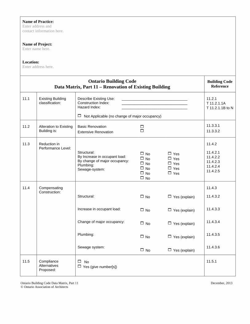
Ontario Building Code Data Matrix, Part 11 – Renovation of Existing Building
Building Code Reference
11.1
Existing Building classification:
Describe Existing Use: ________________________________ Construction Index: ________________________________ Hazard Index: ________________________________ Not Applicable (no change of major occupancy)
11.2.1 T 11.2.1.1A T 11.2.1.1B to N
11.2
Alteration to Existing Building is:
Basic Renovation Extensive Renovation
11.3.3.1 11.3.3.2
11.3
Reduction in Performance Level:
Structural: By Increase in occupant load: By change of major occupancy: Plumbing: Sewage-system:
No No No No No No
Yes Yes Yes Yes Yes
11.4.2 11.4.2.1 11.4.2.2 11.4.2.3 11.4.2.4 11.4.2.5
11.4
Compensating Construction:
Structural: Increase in occupant load: Change of major occupancy: Plumbing: Sewage system:
No No No No No
Yes (explain) Yes (explain) Yes (explain) Yes (explain) Yes (explain)
11.4.3 11.4.3.2 11.4.3.3 11.4.3.4 11.4.3.5 11.4.3.6
11.5
Compliance Alternatives Proposed:
No Yes (give number[s])
11.5.1
Ontario Building Code Data Matrix, Part 11 December, 2013 © Ontario Association of Architects
Note: Numbering is based on SI edition of ASHRAE 90.1-2010. December 23, 2013
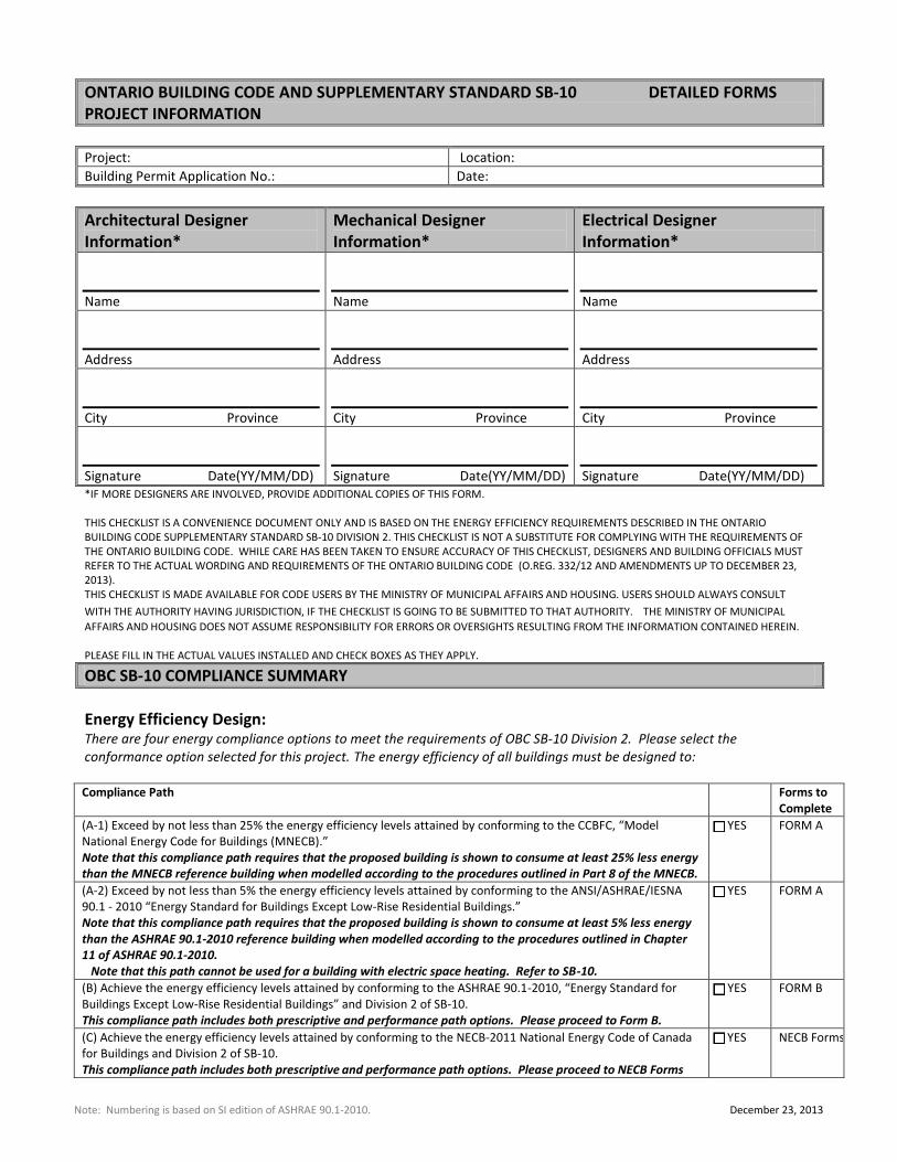
ONTARIO BUILDING CODE AND SUPPLEMENTARY STANDARD SB-10 DETAILED FORMS PROJECT INFORMATION
Project: Location:
Building Permit Application No.: Date:
Architectural Designer Information*
Mechanical Designer Information*
Electrical Designer Information*
Name
Name
Name
Address
Address
Address
City Province
City Province
City Province
Signature Date(YY/MM/DD)
Signature Date(YY/MM/DD)
Signature Date(YY/MM/DD) *IF MORE DESIGNERS ARE INVOLVED, PROVIDE ADDITIONAL COPIES OF THIS FORM. THIS CHECKLIST IS A CONVENIENCE DOCUMENT ONLY AND IS BASED ON THE ENERGY EFFICIENCY REQUIREMENTS DESCRIBED IN THE ONTARIO BUILDING CODE SUPPLEMENTARY STANDARD SB-10 DIVISION 2. THIS CHECKLIST IS NOT A SUBSTITUTE FOR COMPLYING WITH THE REQUIREMENTS OF THE ONTARIO BUILDING CODE. WHILE CARE HAS BEEN TAKEN TO ENSURE ACCURACY OF THIS CHECKLIST, DESIGNERS AND BUILDING OFFICIALS MUST REFER TO THE ACTUAL WORDING AND REQUIREMENTS OF THE ONTARIO BUILDING CODE (O.REG. 332/12 AND AMENDMENTS UP TO DECEMBER 23, 2013). THIS CHECKLIST IS MADE AVAILABLE FOR CODE USERS BY THE MINISTRY OF MUNICIPAL AFFAIRS AND HOUSING. USERS SHOULD ALWAYS CONSULT
WITH THE AUTHORITY HAVING JURISDICTION, IF THE CHECKLIST IS GOING TO BE SUBMITTED TO THAT AUTHORITY. THE MINISTRY OF MUNICIPAL
AFFAIRS AND HOUSING DOES NOT ASSUME RESPONSIBILITY FOR ERRORS OR OVERSIGHTS RESULTING FROM THE INFORMATION CONTAINED HEREIN. PLEASE FILL IN THE ACTUAL VALUES INSTALLED AND CHECK BOXES AS THEY APPLY.
OBC SB-10 COMPLIANCE SUMMARY
Energy Efficiency Design: There are four energy compliance options to meet the requirements of OBC SB-10 Division 2. Please select the conformance option selected for this project. The energy efficiency of all buildings must be designed to: Compliance Path
Forms to Complete
(A-1) Exceed by not less than 25% the energy efficiency levels attained by conforming to the CCBFC, “Model National Energy Code for Buildings (MNECB).” Note that this compliance path requires that the proposed building is shown to consume at least 25% less energy than the MNECB reference building when modelled according to the procedures outlined in Part 8 of the MNECB.
□ YES FORM A
(A-2) Exceed by not less than 5% the energy efficiency levels attained by conforming to the ANSI/ASHRAE/IESNA 90.1 - 2010 “Energy Standard for Buildings Except Low-Rise Residential Buildings.” Note that this compliance path requires that the proposed building is shown to consume at least 5% less energy than the ASHRAE 90.1-2010 reference building when modelled according to the procedures outlined in Chapter 11 of ASHRAE 90.1-2010. Note that this path cannot be used for a building with electric space heating. Refer to SB-10.
□ YES FORM A
(B) Achieve the energy efficiency levels attained by conforming to the ASHRAE 90.1-2010, “Energy Standard for Buildings Except Low-Rise Residential Buildings” and Division 2 of SB-10. This compliance path includes both prescriptive and performance path options. Please proceed to Form B.
□ YES FORM B
(C) Achieve the energy efficiency levels attained by conforming to the NECB-2011 National Energy Code of Canada for Buildings and Division 2 of SB‐10. This compliance path includes both prescriptive and performance path options. Please proceed to NECB Forms
□ YES NECB Forms
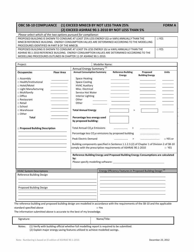
OBC SB‐10 COMPLIANCE (1) EXCEED MNECB BY NOT LESS THAN 25% FORM A
(2) EXCEED ASHRAE 90.1‐2010 BY NOT LESS THAN 5%
Please select which of the two options pursued for compliance:
PROPOSED BUILDING IS SHOWN TO CONSUME AT LEAST 25% LESS ENERGY (GJ or kWh) ANNUALLY THAN THE
MNECB REFERENCE BUILDING. ENERGY CONSUMPTION VALUES ARE DETERMINED ACCORDING TO THE MODELLING
PROCEDURES IDENTIFIED IN PART 8 OF THE MNECB.
□ YES
PROPOSED BUILDING IS SHOWN TO CONSUME AT LEAST 5% LESS ENERGY (GJ or kWh) ANNUALLY THAN THE
ASHRAE 90.1‐2010 REFERENCE BUILDING. ENERGY CONSUMPTION VALUES ARE DETERMINED ACCORDING TO THE
MODELLING PROCEDURES OUTLINED IN CHAPTER 11 OF ASHRAE 90.1‐2010.
□ YES
Project: Modeller Name:
Annual Energy Summary (1)
Occupancies Floor Area
□ Assembly
□ Health/Institutional □ Hotel/Motel □ Light Manufacturing □ Multifamily □ Office
□ Restaurant □ Retail
□ School
□ Warehouse □ Other
Total
□ Proposed Building Description
Annual Consumption Summary Reference Building Proposed Units
Energy Building Energy
Space Heating Space Cooling HVAC Auxiliary Misc. Electrical Service Hot Water Interior Lighting Other Other
Total Annual Energy >
Percentage less energy used
by proposed building:
Total Annual CO2e Emissions ………………… > ………………………..
Percentage less CO2e emissions by proposed building ………………………..
Peak Electric Demand ………………… > ……………………….. □ YES or
Building components specified in Sentence 1.1.2.3.(2) of Chapter 1 of Division 2 of SB‐10
comply with the prescriptive requirements of ASHRAE 90.1‐2010 □ YES
Reference Building Energy and Proposed Building Energy Consumptions are calculated
by:
Please specify modelling software:
HVAC System Descriptions Energy Efficiency Features in Proposed Building Design (2)
Reference Building Design
Proposed Building Design
The reference building and proposed building design are modelled in accordance with the requirements of the SB‐10 and the applicable
standard specified above □ Yes
The information submitted above is accurate to the best of my knowledge.
Signature: Name/Title:
Notes: (1) Verify with building official whether full modelling report is required to be submitted.
(2) Explain major energy saving features utilized to achieve modelled savings.
Note: Numbering is based on SI edition of ASHRAE 90.1‐2010. December 23, 2012
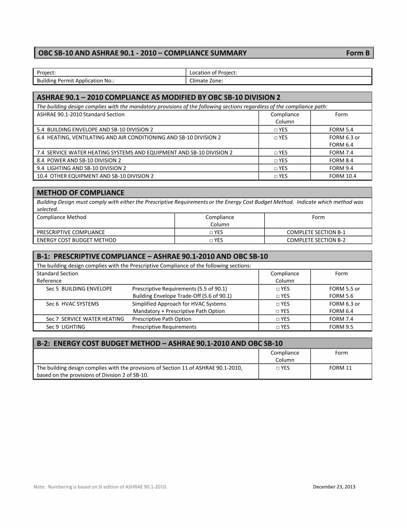
OBC SB‐10 AND ASHRAE 90.1 ‐ 2010 – COMPLIANCE SUMMARY Form B
Project: Location of Project:
Building Permit Application No.: Climate Zone:
ASHRAE 90.1 – 2010 COMPLIANCE AS MODIFIED BY OBC SB‐10 DIVISION 2 The building design complies with the mandatory provisions of the following sections regardless of the compliance path:
ASHRAE 90.1‐2010 Standard Section Compliance
Column
Form
5.4 BUILDING ENVELOPE AND SB‐10 DIVISION 2 □ YES FORM 5.4
6.4 HEATING, VENTILATING AND AIR CONDITIONING AND SB‐10 DIVISION 2 □ YES FORM 6.3 or
FORM 6.4
7.4 SERVICE WATER HEATING SYSTEMS AND EQUIPMENT AND SB‐10 DIVISION 2 □ YES FORM 7.4
8.4 POWER AND SB‐10 DIVISION 2 □ YES FORM 8.4
9.4 LIGHTING AND SB‐10 DIVISION 2 □ YES FORM 9.4
10.4 OTHER EQUIPMENT AND SB‐10 DIVISION 2 □ YES FORM 10.4
METHOD OF COMPLIANCE Building Design must comply with either the Prescriptive Requirements or the Energy Cost Budget Method. Indicate which method was
selected.
Compliance Method Compliance
Column
Form
PRESCRIPTIVE COMPLIANCE □ YES COMPLETE SECTION B‐1
ENERGY COST BUDGET METHOD □ YES COMPLETE SECTION B‐2
B‐1: PRESCRIPTIVE COMPLIANCE – ASHRAE 90.1‐2010 AND OBC SB‐10 The building design complies with the Prescriptive Compliance of the following sections:
Standard Section
Reference
Compliance
Column
Form
Sec 5 BUILDING ENVELOPE Prescriptive Requirements (5.5 of 90.1)
Building Envelope Trade‐Off (5.6 of 90.1)
□ YES
□ YES
FORM 5.5 or
FORM 5.6
Sec 6 HVAC SYSTEMS Simplified Approach for HVAC Systems
Mandatory + Prescriptive Path Option
□ YES
□ YES
FORM 6.3 or
FORM 6.4
Sec 7 SERVICE WATER HEATING Prescriptive Path Option □ YES FORM 7.4
Sec 9 LIGHTING Prescriptive Requirements □ YES FORM 9.5
B‐2: ENERGY COST BUDGET METHOD – ASHRAE 90.1‐2010 AND OBC SB‐10
Compliance
Column
Form
The building design complies with the provisions of Section 11 of ASHRAE 90.1‐2010,
based on the provisions of Division 2 of SB‐10.
□ YES FORM 11
Note: Numbering is based on SI edition of ASHRAE 90.1‐2010. December 23, 2013
Note: Numbering is based on SI edition of ASHRAE 90.1‐2010. April 23, 2012
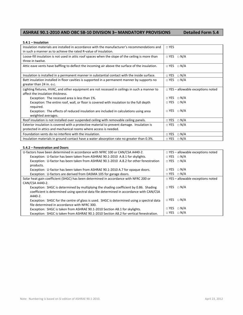
5.4.1 – Insulation
Insulation materials are installed in accordance with the manufacturer’s recommendations and in such a manner as to achieve the rated R‐value of insulation.
□ YES
Loose‐fill insulation is not used in attic roof spaces when the slope of the ceiling is more than three in twelve.
□ YES □ N/A
Attic eave vents have baffling to deflect the incoming air above the surface of the insulation. □ YES □ N/A
Insulation is installed in a permanent manner in substantial contact with the inside surface. □ YES □ N/A Batt insulation installed in floor cavities is supported in a permanent manner by supports no greater than 24 in. o.c.
□ YES □ N/A
Lighting fixtures, HVAC, and other equipment are not recessed in ceilings in such a manner to affect the insulation thickness.
Exception: The recessed area is less than 1%. Exception: The entire roof, wall, or floor is covered with insulation to the full depth required. Exception: The effects of reduced insulation are included in calculations using area weighted averages.
□ YES – allowable exceptions noted □ YES □ N/A □ YES □ N/A □ YES □ N/A
Roof insulation is not installed over suspended ceiling with removable ceiling panels. □ YES □ N/A Exterior insulation is covered with a protective material to prevent damage. Insulation is protected in attics and mechanical rooms where access is needed.
□ YES □ N/A
Foundation vents do no interfere with the insulation. □ YES □ N/A Insulation materials in ground contact have a water absorption rate no greater than 0.3%. □ YES □ N/A 5.4.2 – Fenestration and Doors
U‐factors have been determined in accordance with NFRC 100 or CAN/CSA A440‐2. Exception: U‐factor has been taken from ASHRAE 90.1‐2010 A.8.1 for skylights. Exception: U‐factor has been taken from ASHRAE 90.1‐2010 A.8.2 for other fenestration products. Exception: U‐factor has been taken from ASHRAE 90.1‐2010 A.7 for opaque doors. Exception: U‐factors are derived from DASMA 105 for garage doors.
□ YES – allowable exceptions noted □ YES □ N/A □ YES □ N/A □ YES □ N/A □ YES □ N/A
Solar heat gain coefficient (SHGC) has been determined in accordance with NFRC 200 or CAN/CSA A440‐2.
Exception: SHGC is determined by multiplying the shading coefficient by 0.86. Shading coefficient is determined using spectral data file determined in accordance with CAN/CSA A440‐2. Exception: SHGC for the centre of glass is used. SHGC is determined using a spectral data file determined in accordance with NFRC 300. Exception: SHGC is taken from ASHRAE 90.1‐2010 Section A8.1 for skylights. Exception: SHGC is taken from ASHRAE 90.1‐2010 Section A8.2 for vertical fenestration.
□ YES – allowable exceptions noted □ YES □ N/A □ YES □ N/A □ YES □ N/A □ YES □ N/A
ASHRAE 90.1‐2010 AND OBC SB‐10 DIVISION 3– MANDATORY PROVISIONS Detailed Form 5.4
Note: Numbering is based on SI edition of ASHRAE 90.1‐2010. April 23, 2012
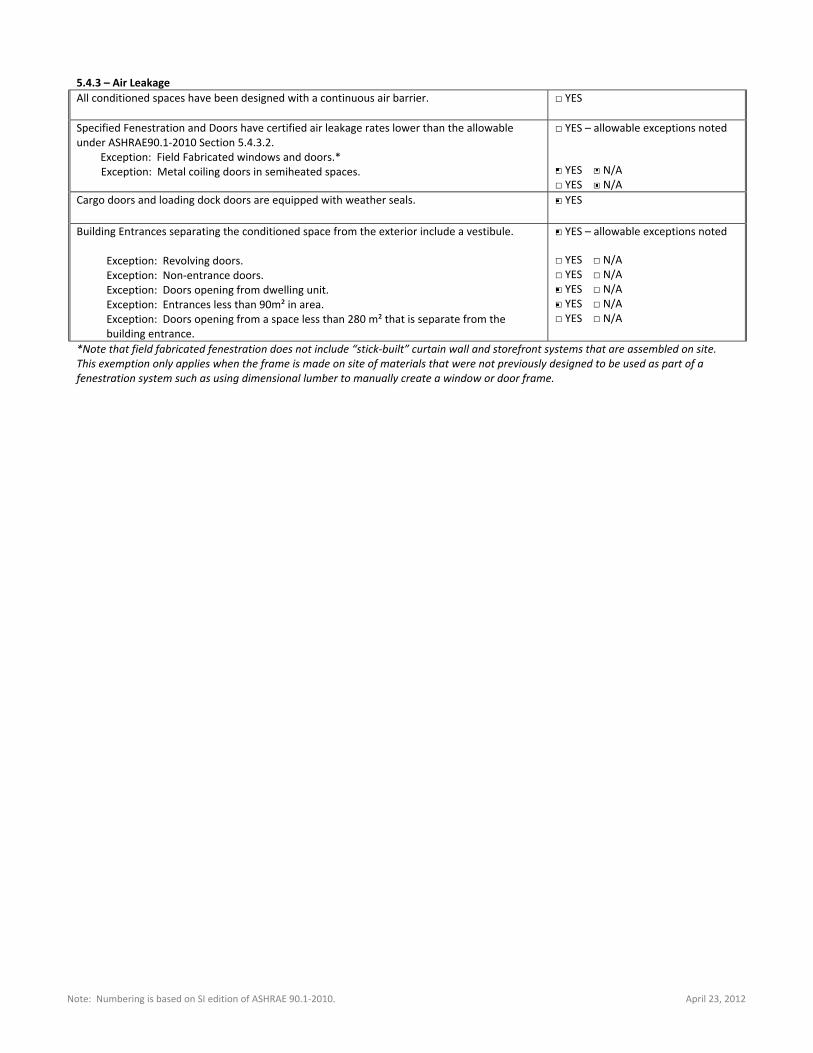
5.4.3 – Air Leakage
All conditioned spaces have been designed with a continuous air barrier.
□ YES
Specified Fenestration and Doors have certified air leakage rates lower than the allowable under ASHRAE90.1‐2010 Section 5.4.3.2.
Exception: Field Fabricated windows and doors.* Exception: Metal coiling doors in semiheated spaces.
□ YES – allowable exceptions noted □ YES □ N/A □ YES □ N/A
Cargo doors and loading dock doors are equipped with weather seals. □ YES
Building Entrances separating the conditioned space from the exterior include a vestibule. Exception: Revolving doors. Exception: Non‐entrance doors. Exception: Doors opening from dwelling unit. Exception: Entrances less than 90m² in area. Exception: Doors opening from a space less than 280 m² that is separate from the building entrance.
□ YES – allowable exceptions noted □ YES □ N/A □ YES □ N/A □ YES □ N/A □ YES □ N/A □ YES □ N/A
*Note that field fabricated fenestration does not include “stick‐built” curtain wall and storefront systems that are assembled on site. This exemption only applies when the frame is made on site of materials that were not previously designed to be used as part of a fenestration system such as using dimensional lumber to manually create a window or door frame.
Note: Numbering is based on SI edition of ASHRAE 90.1‐2010. December 23, 2013
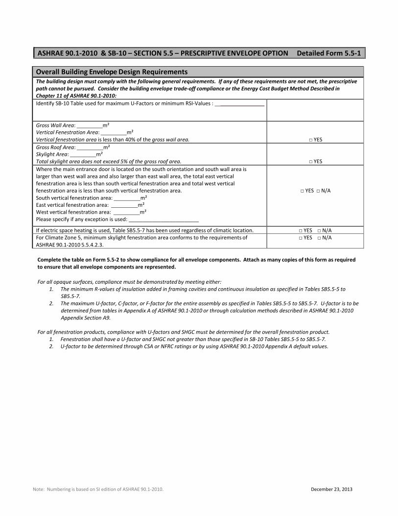
ASHRAE 90.1‐2010 & SB‐10 – SECTION 5.5 – PRESCRIPTIVE ENVELOPE OPTION Detailed Form 5.5‐1
Overall Building Envelope Design Requirements The building design must comply with the following general requirements. If any of these requirements are not met, the prescriptive
path cannot be pursued. Consider the building envelope trade‐off compliance or the Energy Cost Budget Method Described in
Chapter 11 of ASHRAE 90.1‐2010:
Identify SB‐10 Table used for maximum U‐Factors or minimum RSI‐Values : _______________
Gross Wall Area: m²
Vertical Fenestration Area: m²
Vertical fenestration area is less than 40% of the gross wall area.
□ YES
Gross Roof Area: m²
Skylight Area: m²
Total skylight area does not exceed 5% of the gross roof area.
□ YES
Where the main entrance door is located on the south orientation and south wall area is
larger than west wall area and also larger than east wall area, the total east vertical
fenestration area is less than south vertical fenestration area and total west vertical
fenestration area is less than south vertical fenestration area.
South vertical fenestration area: m²
East vertical fenestration area: m²
West vertical fenestration area: m²
Please specify if any exception is used: ________________________
□ YES □ N/A
If electric space heating is used, Table SB5.5‐7 has been used regardless of climatic location. □ YES □ N/A
For Climate Zone 5, minimum skylight fenestration area conforms to the requirements of
ASHRAE 90.1‐2010 5.5.4.2.3.
□ YES □ N/A
Complete the table on Form 5.5‐2 to show compliance for all envelope components. Attach as many copies of this form as required
to ensure that all envelope components are represented.
For all opaque surfaces, compliance must be demonstrated by meeting either:
1. The minimum R‐values of insulation added in framing cavities and continuous insulation as specified in Tables SB5.5‐5 to
SB5.5‐7.
2. The maximum U‐factor, C‐factor, or F‐factor for the entire assembly as specified in Tables SB5.5‐5 to SB5.5‐7. U‐factor is to be
determined from tables in Appendix A of ASHRAE 90.1‐2010 or through calculation methods described in ASHRAE 90.1‐2010
Appendix Section A9.
For all fenestration products, compliance with U‐factors and SHGC must be determined for the overall fenestration product.
1. Fenestration shall have a U‐factor and SHGC not greater than those specified in SB‐10 Tables SB5.5‐5 to SB5.5‐7.
2. U‐factor to be determined through CSA or NFRC ratings or by using ASHRAE 90.1‐2010 Appendix A default values.
Note: Numbering is based on SI edition of ASHRAE 90.1‐2010. December 23, 2013
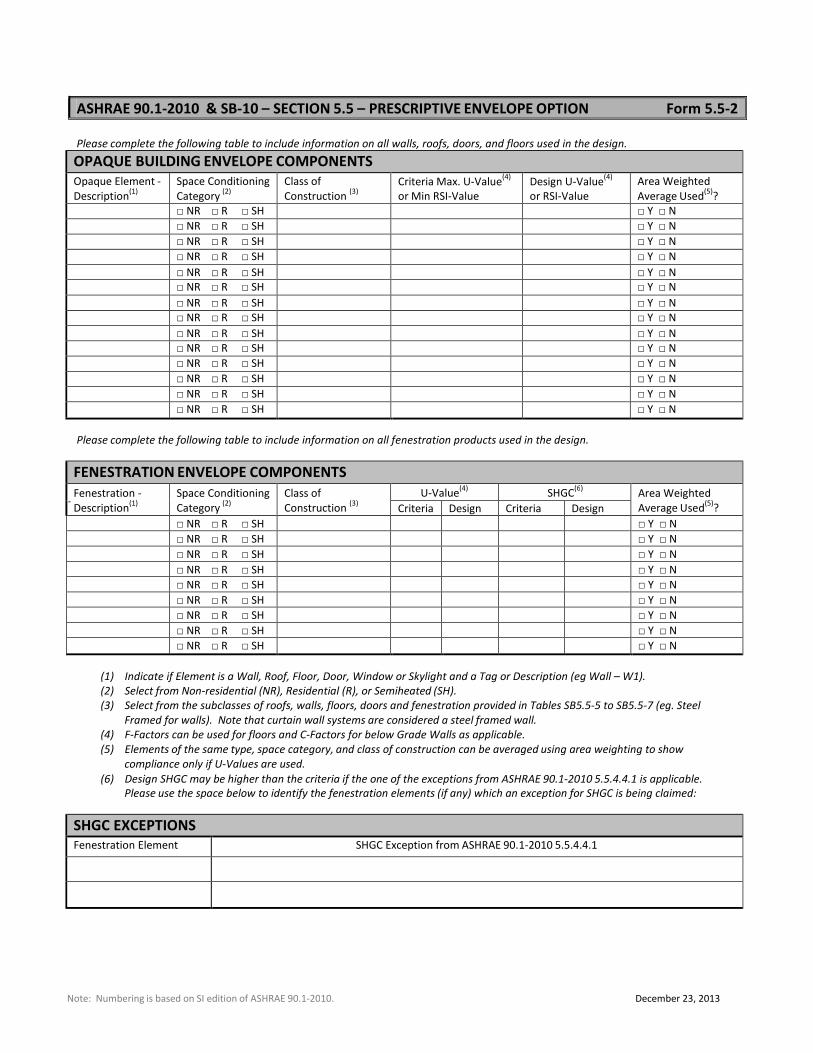
ASHRAE 90.1‐2010 & SB‐10 – SECTION 5.5 – PRESCRIPTIVE ENVELOPE OPTION Form 5.5‐2
Please complete the following table to include information on all walls, roofs, doors, and floors used in the design.
OPAQUE BUILDING ENVELOPE COMPONENTS
Opaque Element ‐
Description(1)
Space Conditioning
Category (2)
Class of
Construction (3)
Criteria Max. U‐Value(4)
or Min RSI‐Value
Design U‐Value(4)
or RSI‐Value
Area Weighted
Average Used(5)
?
□ NR □ R □ SH □ Y □ N
□ NR □ R □ SH □ Y □ N
□ NR □ R □ SH □ Y □ N
□ NR □ R □ SH □ Y □ N
□ NR □ R □ SH □ Y □ N
□ NR □ R □ SH □ Y □ N
□ NR □ R □ SH □ Y □ N
□ NR □ R □ SH □ Y □ N
□ NR □ R □ SH □ Y □ N
□ NR □ R □ SH □ Y □ N
□ NR □ R □ SH □ Y □ N
□ NR □ R □ SH □ Y □ N
□ NR □ R □ SH □ Y □ N
□ NR □ R □ SH □ Y □ N
Please complete the following table to include information on all fenestration products used in the design.
FENESTRATION ENVELOPE COMPONENTS
Fenestration ‐
Description(1)
Space Conditioning
Category (2)
Class of
Construction (3)
U‐Value(4)
SHGC(6)
Area Weighted
Average Used(5)
? Criteria Design Criteria Design
□ NR □ R □ SH □ Y □ N
□ NR □ R □ SH □ Y □ N
□ NR □ R □ SH □ Y □ N
□ NR □ R □ SH □ Y □ N
□ NR □ R □ SH □ Y □ N
□ NR □ R □ SH □ Y □ N
□ NR □ R □ SH □ Y □ N
□ NR □ R □ SH □ Y □ N
□ NR □ R □ SH □ Y □ N
(1) Indicate if Element is a Wall, Roof, Floor, Door, Window or Skylight and a Tag or Description (eg Wall – W1).
(2) Select from Non‐residential (NR), Residential (R), or Semiheated (SH).
(3) Select from the subclasses of roofs, walls, floors, doors and fenestration provided in Tables SB5.5‐5 to SB5.5‐7 (eg. Steel
Framed for walls). Note that curtain wall systems are considered a steel framed wall.
(4) F‐Factors can be used for floors and C‐Factors for below Grade Walls as applicable.
(5) Elements of the same type, space category, and class of construction can be averaged using area weighting to show
compliance only if U‐Values are used.
(6) Design SHGC may be higher than the criteria if the one of the exceptions from ASHRAE 90.1‐2010 5.5.4.4.1 is applicable.
Please use the space below to identify the fenestration elements (if any) which an exception for SHGC is being claimed:
SHGC EXCEPTIONS Fenestration Element SHGC Exception from ASHRAE 90.1‐2010 5.5.4.4.1
Note: Numbering is based on SI edition of ASHRAE 90.1‐2010. December 23, 2013
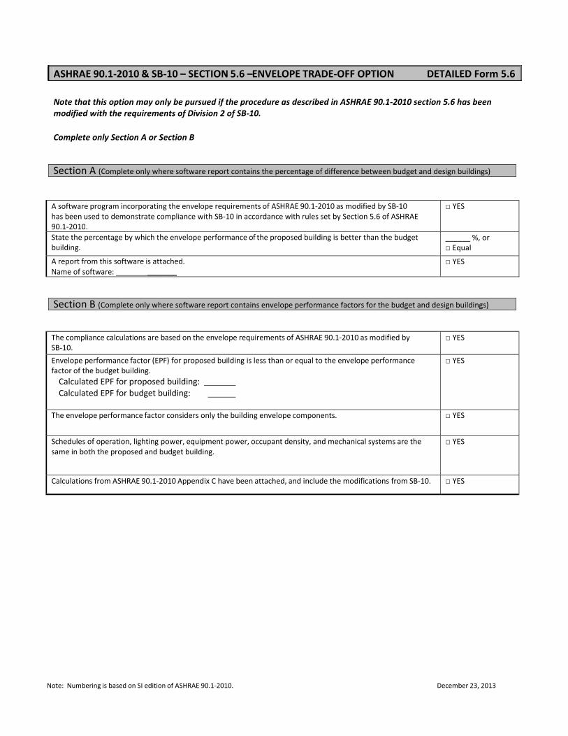
ASHRAE 90.1‐2010 & SB‐10 – SECTION 5.6 –ENVELOPE TRADE‐OFF OPTION DETAILED Form 5.6
Note that this option may only be pursued if the procedure as described in ASHRAE 90.1‐2010 section 5.6 has been
modified with the requirements of Division 2 of SB‐10.
Complete only Section A or Section B
Section A (Complete only where software report contains the percentage of difference between budget and design buildings)
A software program incorporating the envelope requirements of ASHRAE 90.1‐2010 as modified by SB‐10
has been used to demonstrate compliance with SB‐10 in accordance with rules set by Section 5.6 of ASHRAE
90.1‐2010.
□ YES
State the percentage by which the envelope performance of the proposed building is better than the budget
building.
______ %, or
□ Equal
A report from this software is attached.
Name of software: _______
□ YES
Section B (Complete only where software report contains envelope performance factors for the budget and design buildings)
The compliance calculations are based on the envelope requirements of ASHRAE 90.1‐2010 as modified by
SB‐10.
□ YES
Envelope performance factor (EPF) for proposed building is less than or equal to the envelope performance
factor of the budget building.
Calculated EPF for proposed building: Calculated EPF for budget building:
□ YES
The envelope performance factor considers only the building envelope components. □ YES
Schedules of operation, lighting power, equipment power, occupant density, and mechanical systems are the
same in both the proposed and budget building.
□ YES
Calculations from ASHRAE 90.1‐2010 Appendix C have been attached, and include the modifications from SB‐10. □ YES
Note: Numbering is based on SI edition of ASHRAE 90.1‐2010. April 23, 2012
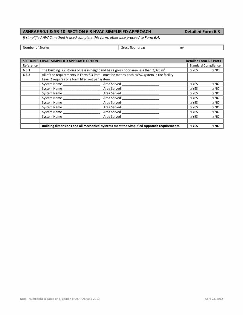
ASHRAE 90.1 & SB‐10‐ SECTION 6.3 HVAC SIMPLIFIED APPROACH Detailed Form 6.3 If simplified HVAC method is used complete this form, otherwise proceed to Form 6.4. Number of Stories: Gross floor area: m² SECTION 6.3 HVAC SIMPLIFIED APPROACH OPTION Detailed Form 6.3 Part I
Reference Standard Compliance 6.3.1 The building is 2 stories or less in height and has a gross floor area less than 2,323 m². □ YES □ NO 6.3.2 All of the requirements in Form 6.3 Part II must be met by each HVAC system in the facility.
Level 2 requires one form filled out per system.
System Name _____________________ Area Served _____________________ □ YES □ NO System Name _____________________ Area Served _____________________ □ YES □ NO System Name _____________________ Area Served _____________________ □ YES □ NO System Name _____________________ Area Served _____________________ □ YES □ NO System Name _____________________ Area Served _____________________ □ YES □ NO System Name _____________________ Area Served _____________________ □ YES □ NO System Name _____________________ Area Served _____________________ □ YES □ NO System Name _____________________ Area Served _____________________ □ YES □ NO Building dimensions and all mechanical systems meet the Simplified Approach requirements. □ YES □ NO
Note: Numbering is based on SI edition of ASHRAE 90.1‐2010. April 23, 2012
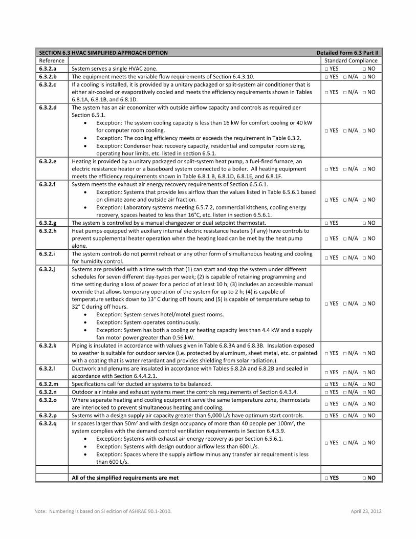
SECTION 6.3 HVAC SIMPLIFIED APPROACH OPTION Detailed Form 6.3 Part II
Reference Standard Compliance 6.3.2.a System serves a single HVAC zone. □ YES □ NO 6.3.2.b The equipment meets the variable flow requirements of Section 6.4.3.10. □ YES □ N/A □ NO 6.3.2.c If a cooling is installed, it is provided by a unitary packaged or split‐system air conditioner that is
either air‐cooled or evaporatively cooled and meets the efficiency requirements shown in Tables 6.8.1A, 6.8.1B, and 6.8.1D.
□ YES □ N/A □ NO
6.3.2.d The system has an air economizer with outside airflow capacity and controls as required per Section 6.5.1.
Exception: The system cooling capacity is less than 16 kW for comfort cooling or 40 kW for computer room cooling.
Exception: The cooling efficiency meets or exceeds the requirement in Table 6.3.2. Exception: Condenser heat recovery capacity, residential and computer room sizing,
operating hour limits, etc. listed in section 6.5.1.
□ YES □ N/A □ NO
6.3.2.e Heating is provided by a unitary packaged or split‐system heat pump, a fuel‐fired furnace, an electric resistance heater or a baseboard system connected to a boiler. All heating equipment meets the efficiency requirements shown in Table 6.8.1 B, 6.8.1D, 6.8.1E, and 6.8.1F.
□ YES □ N/A □ NO
6.3.2.f System meets the exhaust air energy recovery requirements of Section 6.5.6.1. Exception: Systems that provide less airflow than the values listed in Table 6.5.6.1 based
on climate zone and outside air fraction. Exception: Laboratory systems meeting 6.5.7.2, commercial kitchens, cooling energy
recovery, spaces heated to less than 16°C, etc. listen in section 6.5.6.1.
□ YES □ N/A □ NO
6.3.2.g The system is controlled by a manual changeover or dual setpoint thermostat. □ YES □ NO 6.3.2.h Heat pumps equipped with auxiliary internal electric resistance heaters (if any) have controls to
prevent supplemental heater operation when the heating load can be met by the heat pump alone.
□ YES □ N/A □ NO
6.3.2.i The system controls do not permit reheat or any other form of simultaneous heating and cooling for humidity control. □ YES □ N/A □ NO
6.3.2.j Systems are provided with a time switch that (1) can start and stop the system under different schedules for seven different day‐types per week; (2) is capable of retaining programming and time setting during a loss of power for a period of at least 10 h; (3) includes an accessible manual override that allows temporary operation of the system for up to 2 h; (4) is capable of temperature setback down to 13° C during off hours; and (5) is capable of temperature setup to 32° C during off hours.
Exception: System serves hotel/motel guest rooms. Exception: System operates continuously. Exception: System has both a cooling or heating capacity less than 4.4 kW and a supply
fan motor power greater than 0.56 kW.
□ YES □ N/A □ NO
6.3.2.k Piping is insulated in accordance with values given in Table 6.8.3A and 6.8.3B. Insulation exposed to weather is suitable for outdoor service (i.e. protected by aluminum, sheet metal, etc. or painted with a coating that is water retardant and provides shielding from solar radiation.).
□ YES □ N/A □ NO
6.3.2.l Ductwork and plenums are insulated in accordance with Tables 6.8.2A and 6.8.2B and sealed in accordance with Section 6.4.4.2.1. □ YES □ N/A □ NO
6.3.2.m Specifications call for ducted air systems to be balanced. □ YES □ N/A □ NO 6.3.2.n Outdoor air intake and exhaust systems meet the controls requirements of Section 6.4.3.4. □ YES □ N/A □ NO 6.3.2.o Where separate heating and cooling equipment serve the same temperature zone, thermostats
are interlocked to prevent simultaneous heating and cooling. □ YES □ N/A □ NO
6.3.2.p Systems with a design supply air capacity greater than 5,000 L/s have optimum start controls. □ YES □ N/A □ NO 6.3.2.q In spaces larger than 50m² and with design occupancy of more than 40 people per 100m², the
system complies with the demand control ventilation requirements in Section 6.4.3.9. Exception: Systems with exhaust air energy recovery as per Section 6.5.6.1. Exception: Systems with design outdoor airflow less than 600 L/s. Exception: Spaces where the supply airflow minus any transfer air requirement is less
than 600 L/s.
□ YES □ N/A □ NO
All of the simplified requirements are met □ YES □ NO
Note: Numbering is based on SI edition of ASHRAE 90.1‐2010. December 23, 2013
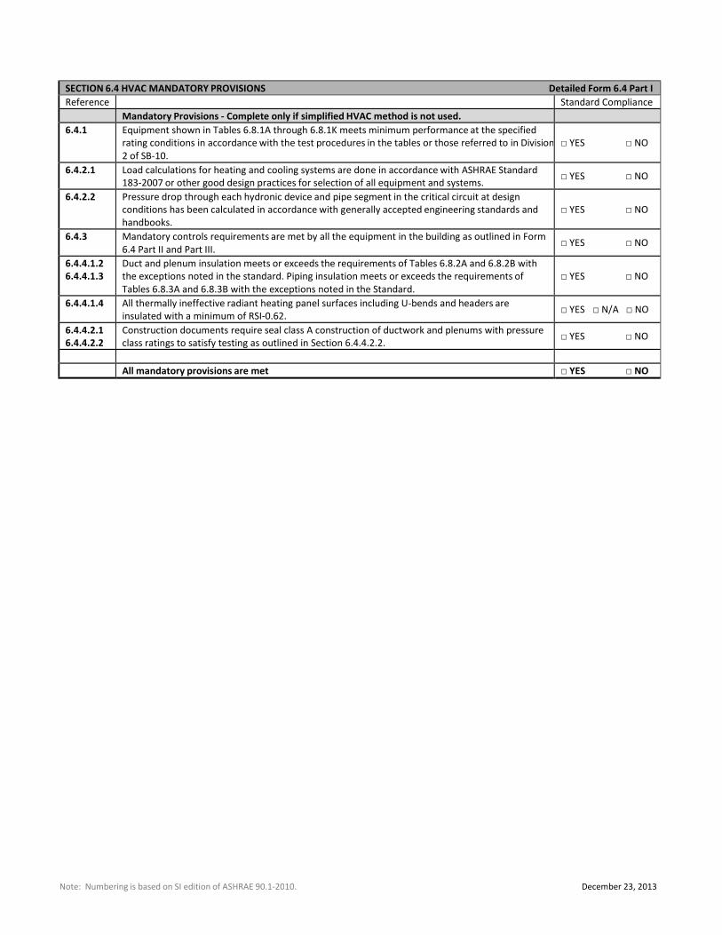
SECTION 6.4 HVAC MANDATORY PROVISIONS Detailed Form 6.4 Part I
Reference Standard Compliance
Mandatory Provisions ‐ Complete only if simplified HVAC method is not used. 6.4.1 Equipment shown in Tables 6.8.1A through 6.8.1K meets minimum performance at the specified
rating conditions in accordance with the test procedures in the tables or those referred to in Division
2 of SB‐10.
□ YES □ NO
6.4.2.1 Load calculations for heating and cooling systems are done in accordance with ASHRAE Standard
183‐2007 or other good design practices for selection of all equipment and systems.
□ YES □ NO
6.4.2.2 Pressure drop through each hydronic device and pipe segment in the critical circuit at design
conditions has been calculated in accordance with generally accepted engineering standards and
handbooks.
□ YES □ NO
6.4.3 Mandatory controls requirements are met by all the equipment in the building as outlined in Form
6.4 Part II and Part III.
□ YES □ NO
6.4.4.1.2
6.4.4.1.3
Duct and plenum insulation meets or exceeds the requirements of Tables 6.8.2A and 6.8.2B with
the exceptions noted in the standard. Piping insulation meets or exceeds the requirements of
Tables 6.8.3A and 6.8.3B with the exceptions noted in the Standard.
□ YES □ NO
6.4.4.1.4 All thermally ineffective radiant heating panel surfaces including U‐bends and headers are
insulated with a minimum of RSI‐0.62.
□ YES □ N/A □ NO
6.4.4.2.1
6.4.4.2.2
Construction documents require seal class A construction of ductwork and plenums with pressure
class ratings to satisfy testing as outlined in Section 6.4.4.2.2.
□ YES □ NO
All mandatory provisions are met □ YES □ NO
Note: Numbering is based on SI edition of ASHRAE 90.1‐2010. December 23, 2013
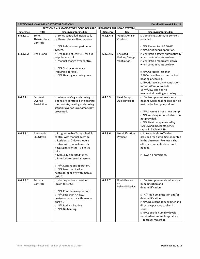
SECTION 6.4 HVAC MANDATORY PROVISIONS Detailed Form 6.4 Part II
SECTION 6.4.3 MANDATORY CONTROLS REQUIREMENTS FOR HVAC SYSTEM Reference Title Check Appropriate Box Reference Title Check Appropriate Box
6.4.3.1.1 Zone
Thermostatic
Controls
□ Zones controlled Individually
by thermostats within the zone.
□ N/A Independent perimeter
system.
6.4.3.4.4 Ventilation Fan
Controls
□ Complying automatic controls
provided.
□ N/A Fan motor ≤ 0.56kW.
□ N/A Continuous operation.
6.4.3.1.2 Dead Band □ Deadband at least 3°C for dual
setpoint control.
□ Manual change over control.
□ N/A Special occupancy
(requires approval).
□ N/A Heating or cooling only.
6.4.3.4.5 Enclosed
Parking Garage
Ventilation
□ Ventilation stages automatically
when contaminants are low.
□ Ventilation modulates down
when contaminants are low.
□ N/A Garage is less than
2,800m² and has no mechanical
heating or cooling.
□ N/A Garage area to ventilation
motor kW ratio exceeds
187m²/kW and has no
mechanical heating or cooling.
6.4.3.2 Setpoint
Overlap
Restriction
□ Where heaƟng and cooling to
a zone are controlled by separate
thermostats, heating and cooling
setpoint overlap is automatically
prevented.
6.4.3.5 Heat Pump
Auxiliary Heat
□ Controls prevent resistance
heating when heating load can be
met by the heat pump alone.
□ N/A System is not a heat pump.
□ N/A Auxiliary is not electric or is
not provided.
□ N/A Heat pump covered by
NAECA and meets efficiency
rating in Table 6.8.1B.
6.4.3.3.1 Automatic
Shutdown
□ Programmable 7‐day schedule
control with manual override.
□ Residential 2‐day schedule
control with manual override.
□ Occupant sensor – up to 30
mins.
□ Manually operated timer.
□ Interlock to security system.
□ N/A Continuous operation.
□ N/A Less than 4.4 kW.
heat/cool capacity with manual
on/off.
6.4.3.6 Humidification
Preheat
□ Automatic shutoff valve
provided for humidifiers mounted
in the airstream. Preheat is shut
off when humidification is not
needed.
□ N/A No humidifier.
6.4.3.3.2 Setback
Controls
□ Heating setback provided
(down to 13°C).
□ N/A Continuous operation.
□ N/A Less than 4.4 kW.
heat/cool capacity with manual
on/off .
□ N/A Radiant heating.
□ N/A No heating.
6.4.3.7 Humidification
and
Dehumidification
□ Controls prevent simultaneous
humidification and
dehumidification.
□ N/A No humidification and/or
dehumidification.
□ N/A Desiccant dehumidifier and
direct evaporative cooling in
series.
□ N/A Specific humidity levels
required (museum, hospital, etc.
– approval required).
Note: Numbering is based on SI edition of ASHRAE 90.1‐2010. December 23, 2013
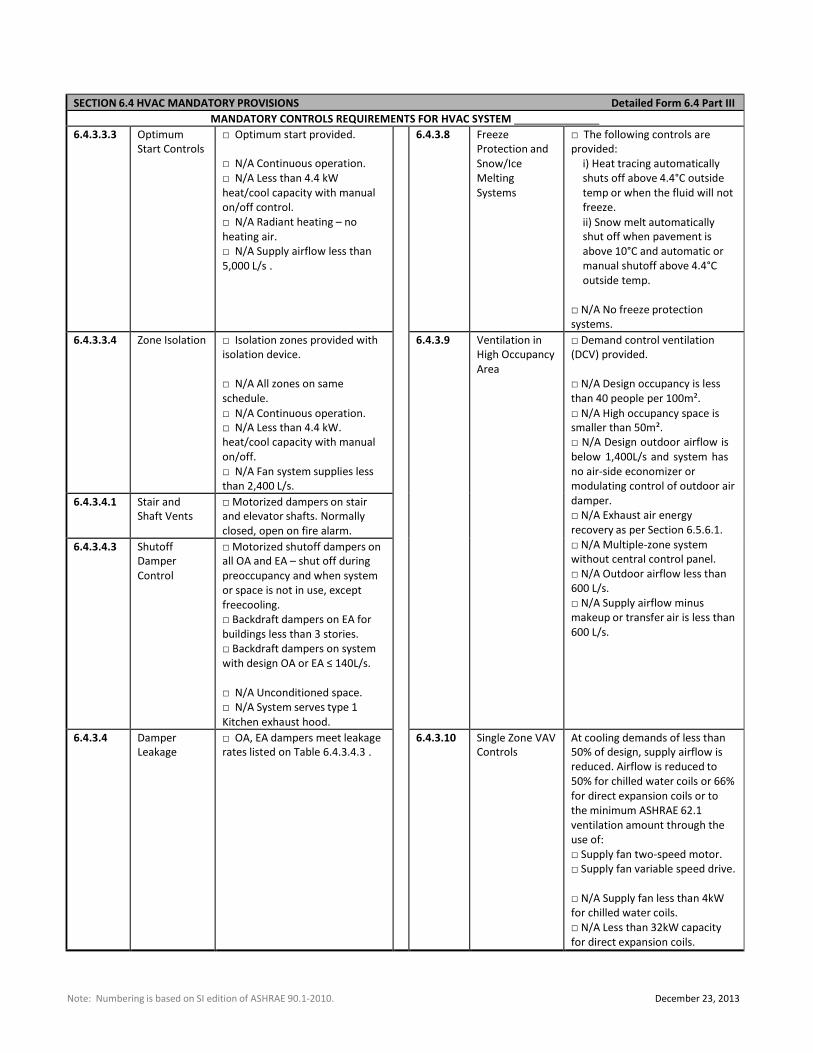
SECTION 6.4 HVAC MANDATORY PROVISIONS Detailed Form 6.4 Part III
MANDATORY CONTROLS REQUIREMENTS FOR HVAC SYSTEM 6.4.3.3.3 Optimum
Start Controls
□ Optimum start provided.
□ N/A Continuous operation.
□ N/A Less than 4.4 kW
heat/cool capacity with manual
on/off control.
□ N/A Radiant heating – no
heating air.
□ N/A Supply airflow less than
5,000 L/s .
6.4.3.8 Freeze
Protection and
Snow/Ice
Melting
Systems
□ The following controls are
provided:
i) Heat tracing automatically
shuts off above 4.4°C outside
temp or when the fluid will not
freeze.
ii) Snow melt automatically
shut off when pavement is
above 10°C and automatic or
manual shutoff above 4.4°C
outside temp.
□ N/A No freeze protection
systems.
6.4.3.3.4 Zone Isolation □ Isolation zones provided with
isolation device.
□ N/A All zones on same
schedule.
□ N/A Continuous operation.
□ N/A Less than 4.4 kW.
heat/cool capacity with manual
on/off.
□ N/A Fan system supplies less
than 2,400 L/s.
6.4.3.9 Ventilation in
High Occupancy
Area
□ Demand control ventilation
(DCV) provided.
□ N/A Design occupancy is less
than 40 people per 100m².
□ N/A High occupancy space is
smaller than 50m².
□ N/A Design outdoor airflow is
below 1,400L/s and system has
no air‐side economizer or
modulating control of outdoor air
damper.
□ N/A Exhaust air energy
recovery as per Section 6.5.6.1.
□ N/A Multiple‐zone system
without central control panel.
□ N/A Outdoor airflow less than
600 L/s.
□ N/A Supply airflow minus
makeup or transfer air is less than
600 L/s.
6.4.3.4.1 Stair and
Shaft Vents
□ Motorized dampers on stair
and elevator shafts. Normally
closed, open on fire alarm.
6.4.3.4.3 Shutoff
Damper
Control
□ Motorized shutoff dampers on
all OA and EA – shut off during
preoccupancy and when system
or space is not in use, except
freecooling.
□ Backdraft dampers on EA for
buildings less than 3 stories.
□ Backdraft dampers on system
with design OA or EA ≤ 140L/s.
□ N/A Unconditioned space.
□ N/A System serves type 1
Kitchen exhaust hood.
6.4.3.4 Damper
Leakage
□ OA, EA dampers meet leakage
rates listed on Table 6.4.3.4.3 . 6.4.3.10 Single Zone VAV
Controls
At cooling demands of less than
50% of design, supply airflow is
reduced. Airflow is reduced to
50% for chilled water coils or 66%
for direct expansion coils or to
the minimum ASHRAE 62.1
ventilation amount through the
use of:
□ Supply fan two‐speed motor.
□ Supply fan variable speed drive.
□ N/A Supply fan less than 4kW
for chilled water coils.
□ N/A Less than 32kW capacity
for direct expansion coils.
Note: Numbering is based on SI edition of ASHRAE 90.1‐2010. April 23, 2012
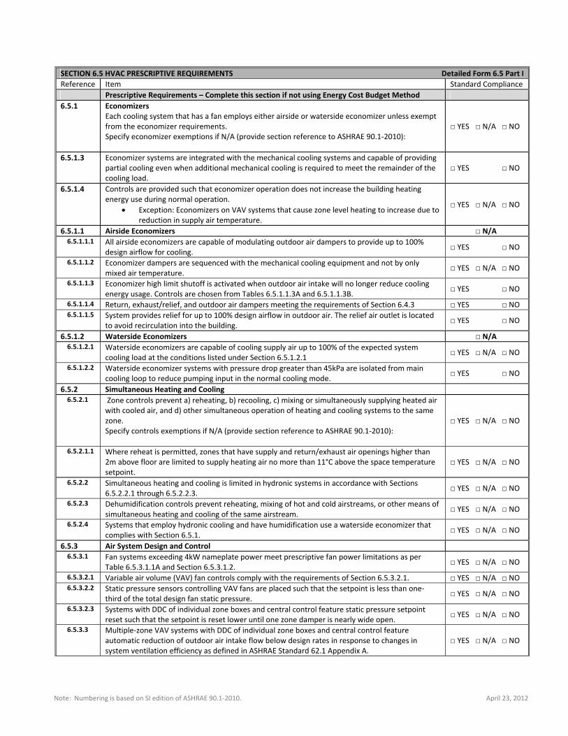
SECTION 6.5 HVAC PRESCRIPTIVE REQUIREMENTS Detailed Form 6.5 Part I
Reference Item Standard Compliance Prescriptive Requirements – Complete this section if not using Energy Cost Budget Method
6.5.1 Economizers Each cooling system that has a fan employs either airside or waterside economizer unless exempt from the economizer requirements. Specify economizer exemptions if N/A (provide section reference to ASHRAE 90.1‐2010):
□ YES □ N/A □ NO
6.5.1.3 Economizer systems are integrated with the mechanical cooling systems and capable of providing partial cooling even when additional mechanical cooling is required to meet the remainder of the cooling load.
□ YES □ NO
6.5.1.4 Controls are provided such that economizer operation does not increase the building heating energy use during normal operation.
Exception: Economizers on VAV systems that cause zone level heating to increase due to reduction in supply air temperature.
□ YES □ N/A □ NO
6.5.1.1 Airside Economizers □ N/A 6.5.1.1.1 All airside economizers are capable of modulating outdoor air dampers to provide up to 100%
design airflow for cooling. □ YES □ NO
6.5.1.1.2 Economizer dampers are sequenced with the mechanical cooling equipment and not by only mixed air temperature. □ YES □ N/A □ NO
6.5.1.1.3 Economizer high limit shutoff is activated when outdoor air intake will no longer reduce cooling energy usage. Controls are chosen from Tables 6.5.1.1.3A and 6.5.1.1.3B. □ YES □ NO
6.5.1.1.4 Return, exhaust/relief, and outdoor air dampers meeting the requirements of Section 6.4.3 □ YES □ NO 6.5.1.1.5 System provides relief for up to 100% design airflow in outdoor air. The relief air outlet is located
to avoid recirculation into the building. □ YES □ NO
6.5.1.2 Waterside Economizers □ N/A 6.5.1.2.1 Waterside economizers are capable of cooling supply air up to 100% of the expected system
cooling load at the conditions listed under Section 6.5.1.2.1 □ YES □ N/A □ NO
6.5.1.2.2 Waterside economizer systems with pressure drop greater than 45kPa are isolated from main cooling loop to reduce pumping input in the normal cooling mode. □ YES □ NO
6.5.2 Simultaneous Heating and Cooling 6.5.2.1 Zone controls prevent a) reheating, b) recooling, c) mixing or simultaneously supplying heated air
with cooled air, and d) other simultaneous operation of heating and cooling systems to the same zone. Specify controls exemptions if N/A (provide section reference to ASHRAE 90.1‐2010):
□ YES □ N/A □ NO
6.5.2.1.1 Where reheat is permitted, zones that have supply and return/exhaust air openings higher than 2m above floor are limited to supply heating air no more than 11°C above the space temperature setpoint.
□ YES □ N/A □ NO
6.5.2.2 Simultaneous heating and cooling is limited in hydronic systems in accordance with Sections 6.5.2.2.1 through 6.5.2.2.3. □ YES □ N/A □ NO
6.5.2.3 Dehumidification controls prevent reheating, mixing of hot and cold airstreams, or other means of simultaneous heating and cooling of the same airstream. □ YES □ N/A □ NO
6.5.2.4 Systems that employ hydronic cooling and have humidification use a waterside economizer that complies with Section 6.5.1. □ YES □ N/A □ NO
6.5.3 Air System Design and Control 6.5.3.1 Fan systems exceeding 4kW nameplate power meet prescriptive fan power limitations as per
Table 6.5.3.1.1A and Section 6.5.3.1.2. □ YES □ N/A □ NO
6.5.3.2.1 Variable air volume (VAV) fan controls comply with the requirements of Section 6.5.3.2.1. □ YES □ N/A □ NO 6.5.3.2.2 Static pressure sensors controlling VAV fans are placed such that the setpoint is less than one‐
third of the total design fan static pressure. □ YES □ N/A □ NO
6.5.3.2.3 Systems with DDC of individual zone boxes and central control feature static pressure setpoint reset such that the setpoint is reset lower until one zone damper is nearly wide open. □ YES □ N/A □ NO
6.5.3.3 Multiple‐zone VAV systems with DDC of individual zone boxes and central control feature automatic reduction of outdoor air intake flow below design rates in response to changes in system ventilation efficiency as defined in ASHRAE Standard 62.1 Appendix A.
□ YES □ N/A □ NO
Note: Numbering is based on SI edition of ASHRAE 90.1‐2010. April 23, 2012
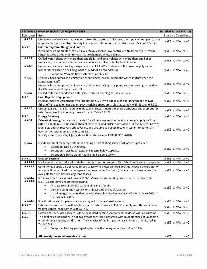
SECTION 6.5 HVAC PRESCRIPTIVE REQUIREMENTS Detailed Form 6.5 Part II
Reference Item Standard Compliance 6.5.3.4 Multiple‐zone VAV systems include controls that automatically reset the supply air temperature in
response to representative building loads, or to outdoor air temperature as per Section 6.5.3.4. □ YES □ N/A □ NO
6.5.4.1
Hydronic System Design and Control Pumping systems greater than 7.5 kW employ variable flow controls, with differential pressure sensor located at the most remote heat exchanger, unless exempt.
□ YES □ N/A □ NO
6.5.4.2
Chilled water plants with more than one chiller and boiler plants with more than one boiler reduce loop water flow automatically whenever a chiller or boiler is shut down. □ YES □ N/A □ NO
6.5.4.3 Hydronic systems exceeding design capacity of 88 kW include controls to reset supply water temperature based on building loads or outdoor air temperature.
Exception: Variable flow systems as per 6.5.4.1. □ YES □ N/A □ NO
6.5.4.4 Hydronic heat pumps and unitary air‐conditioners include automatic water shutoff when the compressor is off. Hydronic heat pumps and unitary air‐conditioners having total pump system power greater than 3.7 kW have variable speed control.
□ YES □ N/A □ NO
6.5.4.5 Chilled water and condenser water pipe is sized according to Table 6.5.4.5. □ YES □ N/A □ NO 6.5.5 Heat Rejection Equipment
All heat rejection equipment with fan motors > 5.6 kW is capable of operating the fan at two‐thirds of full speed or less and employs variable speed controls that comply with Section 6.5.5.2.
□ YES □ N/A □ NO
6.5.5.3 Unducted centrifugal fan open‐circuit cooling towers meet the energy efficiency requirement for axial fan open‐circuit cooling towers listed in Table 6.8.1G. □ YES □ N/A □ NO
6.5.6 Energy Recovery □ YES □ N/A □ NO 6.5.6.1
Exhaust air energy recovery is provided for all fan systems that meet the design supply air flows listed on Table 6.5.6.1 based on their climate zone and outside air fraction. These systems have at least 50% energy recovery effectiveness and are able to bypass recovery system to permit air economizer operation as per Section 6.5.1.1. Specify exemptions if N/A (provide section reference to ASHRAE 90.1‐2010):
□ YES □ N/A □ NO
6.5.6.2 Condenser heat recovery system for heating or preheating service hot water is provided. Exception: Not a 24h facility. Exception: Total heat rejection capacity below 1,800kW. Exception: Service water heating load below 300kW.
□ YES □ N/A □ NO
6.5.7.1 Exhaust Systems □ YES □ N/A □ NO 6.5.7.1.1 Replacement air introduced to kitchen hoods does not exceed 10% of the hood’s exhaust capacity □ YES □ N/A □ NO 6.5.7.1.2 Conditioned supply air delivered to any space with a kitchen hood does not exceed the greater of
a) supply flow required to meet space heating/cooling loads or b) hood exhaust flow minus the available transfer air from adjacent spaces.
□ YES □ N/A □ NO
6.5.7.1.3 6.5.7.1.4
Kitchens with total exhaust flows > 2,360 L/S use hoods meeting exhaust rates listed on Table 6.5.7.1.3 and have one of the following:
At least 50% of all replacement air is transfer air. Demand ventilation system on at least 75% of the exhaust air. Listed energy recovery devices with sensible effectiveness over 40% on at least 50% of
the exhaust airflow.
□ YES □ N/A □ NO
6.5.7.1.5 Specifications call for performance testing of kitchen exhaust systems. □ YES □ N/A □ NO 6.5.7.2 Laboratory fume hoods with a total exhaust system flow > 2,360 L/S comply with the variable air
volume control requirements of 6.5.7.2. □ YES □ N/A □ NO
6.5.8.1 Heating of unenclosed spaces is done by radiant heating, except loading docks with air curtains. □ YES □ N/A □ NO 6.5.9 The cooling equipment with hot‐gas bypass controls is designed with multiple steps of unloading
or continuous capacity modulation. The capacity of the hot gas bypass is limited as indicated in Table 6.5.9.
Exception: Unitary packaged systems with cooling capacities below 26 kW.
□ YES □ N/A □ NO
All prescriptive requirements are met. □ YES □ NO
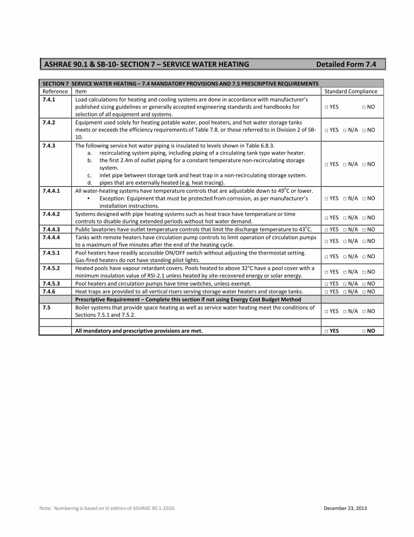
ASHRAE 90.1 & SB‐10‐ SECTION 7 – SERVICE WATER HEATING Detailed Form 7.4
SECTION 7 SERVICE WATER HEATING – 7.4 MANDATORY PROVISIONS AND 7.5 PRESCRIPTIVE REQUIREMENTS
Reference Item Standard Compliance
7.4.1 Load calculations for heating and cooling systems are done in accordance with manufacturer’s
published sizing guidelines or generally accepted engineering standards and handbooks for
selection of all equipment and systems.
□ YES □ NO
7.4.2 Equipment used solely for heating potable water, pool heaters, and hot water storage tanks
meets or exceeds the efficiency requirements of Table 7.8. or those referred to in Division 2 of SB‐
10.
□ YES □ N/A □ NO
7.4.3 The following service hot water piping is insulated to levels shown in Table 6.8.3.
a. recirculating system piping, including piping of a circulating tank type water heater.
b. the first 2.4m of outlet piping for a constant temperature non‐recirculating storage
system.
c. inlet pipe between storage tank and heat trap in a non‐recirculating storage system.
d. pipes that are externally heated (e.g. heat tracing).
□ YES □ N/A □ NO
7.4.4.1 All water‐heating systems have temperature controls that are adjustable down to 49oC or lower.
• Exception: Equipment that must be protected from corrosion, as per manufacturer’s
installation instructions.
□ YES □ N/A □ NO
7.4.4.2 Systems designed with pipe heating systems such as heat trace have temperature or time
controls to disable during extended periods without hot water demand.
□ YES □ N/A □ NO
7.4.4.3 Public lavatories have outlet temperature controls that limit the discharge temperature to 43oC. □ YES □ N/A □ NO
7.4.4.4 Tanks with remote heaters have circulation pump controls to limit operation of circulation pumps
to a maximum of five minutes after the end of the heating cycle.
□ YES □ N/A □ NO
7.4.5.1 Pool heaters have readily accessible ON/OFF switch without adjusting the thermostat setting.
Gas‐fired heaters do not have standing pilot lights.
□ YES □ N/A □ NO
7.4.5.2 Heated pools have vapour retardant covers. Pools heated to above 32°C have a pool cover with a
minimum insulation value of RSI‐2.1 unless heated by site‐recovered energy or solar energy.
□ YES □ N/A □ NO
7.4.5.3 Pool heaters and circulation pumps have time switches, unless exempt. □ YES □ N/A □ NO
7.4.6 Heat traps are provided to all vertical risers serving storage water heaters and storage tanks. □ YES □ N/A □ NO
Prescriptive Requirement – Complete this section if not using Energy Cost Budget Method 7.5 Boiler systems that provide space heating as well as service water heating meet the conditions of
Sections 7.5.1 and 7.5.2.
□ YES □ N/A □ NO
All mandatory and prescriptive provisions are met. □ YES □ NO
Note: Numbering is based on SI edition of ASHRAE 90.1‐2010. December 23, 2013
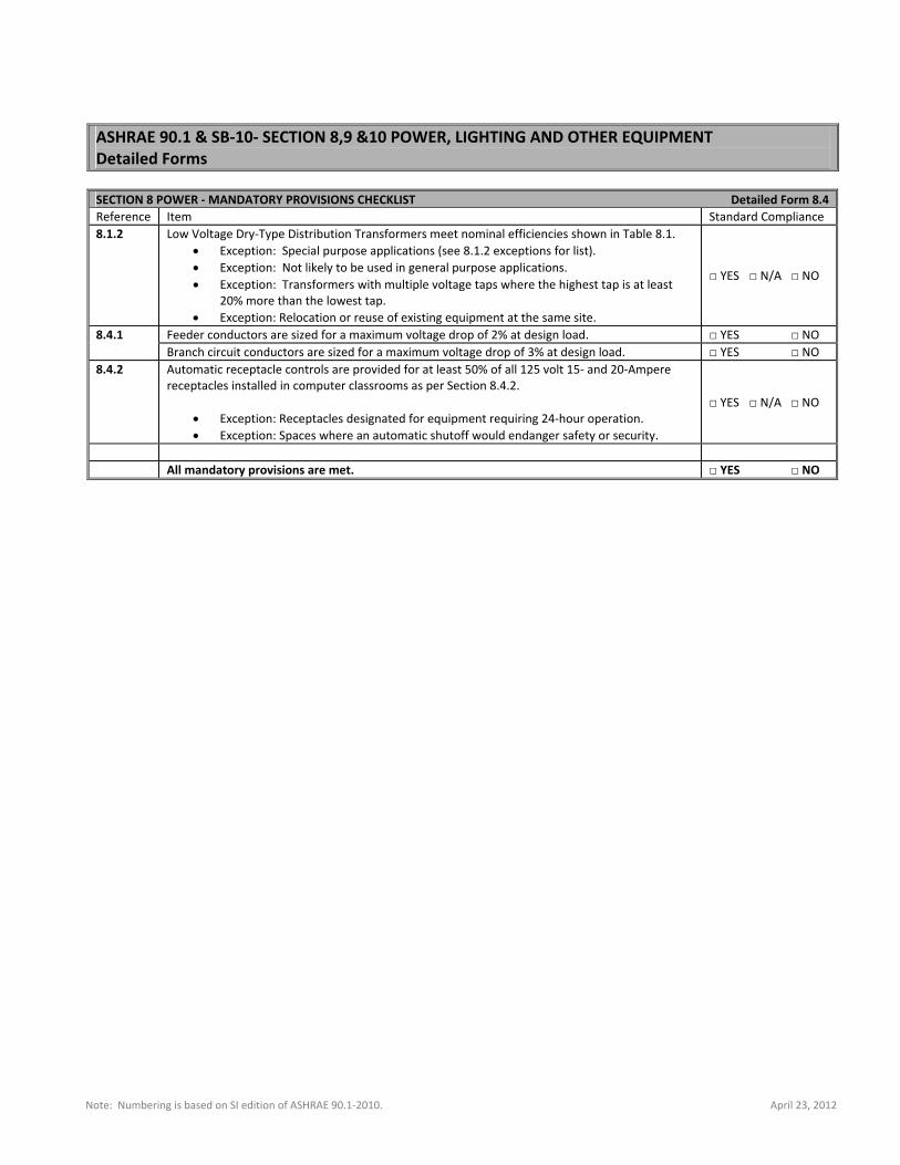
Note: Numbering is based on SI edition of ASHRAE 90.1‐2010. April 23, 2012
ASHRAE 90.1 & SB‐10‐ SECTION 8,9 &10 POWER, LIGHTING AND OTHER EQUIPMENT Detailed Forms SECTION 8 POWER ‐ MANDATORY PROVISIONS CHECKLIST Detailed Form 8.4
Reference Item Standard Compliance 8.1.2 Low Voltage Dry‐Type Distribution Transformers meet nominal efficiencies shown in Table 8.1.
Exception: Special purpose applications (see 8.1.2 exceptions for list). Exception: Not likely to be used in general purpose applications. Exception: Transformers with multiple voltage taps where the highest tap is at least
20% more than the lowest tap. Exception: Relocation or reuse of existing equipment at the same site.
□ YES □ N/A □ NO
8.4.1 Feeder conductors are sized for a maximum voltage drop of 2% at design load. □ YES □ NO Branch circuit conductors are sized for a maximum voltage drop of 3% at design load. □ YES □ NO
8.4.2
Automatic receptacle controls are provided for at least 50% of all 125 volt 15‐ and 20‐Ampere receptacles installed in computer classrooms as per Section 8.4.2.
Exception: Receptacles designated for equipment requiring 24‐hour operation. Exception: Spaces where an automatic shutoff would endanger safety or security.
□ YES □ N/A □ NO
All mandatory provisions are met. □ YES □ NO
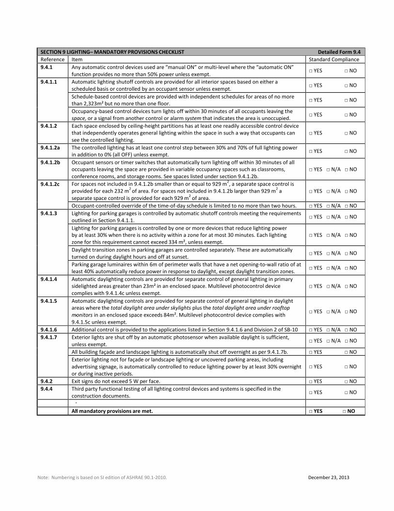
SECTION 9 LIGHTING– MANDATORY PROVISIONS CHECKLIST Detailed Form 9.4
Reference Item Standard Compliance
9.4.1 Any automatic control devices used are “manual ON” or multi‐level where the “automatic ON”
function provides no more than 50% power unless exempt.
□ YES □ NO
9.4.1.1 Automatic lighting shutoff controls are provided for all interior spaces based on either a
scheduled basis or controlled by an occupant sensor unless exempt.
□ YES □ NO
Schedule‐based control devices are provided with independent schedules for areas of no more
than 2,323m² but no more than one floor.
□ YES □ NO
Occupancy‐based control devices turn lights off within 30 minutes of all occupants leaving the
space, or a signal from another control or alarm system that indicates the area is unoccupied.
□ YES □ NO
9.4.1.2 Each space enclosed by ceiling‐height partitions has at least one readily accessible control device
that independently operates general lighting within the space in such a way that occupants can
see the controlled lighting.
□ YES □ NO
9.4.1.2a The controlled lighting has at least one control step between 30% and 70% of full lighting power
in addition to 0% (all OFF) unless exempt.
□ YES □ NO
9.4.1.2b Occupant sensors or timer switches that automatically turn lighting off within 30 minutes of all
occupants leaving the space are provided in variable occupancy spaces such as classrooms,
conference rooms, and storage rooms. See spaces listed under section 9.4.1.2b.
□ YES □ N/A □ NO
9.4.1.2c For spaces not included in 9.4.1.2b smaller than or equal to 929 m2, a separate space control is
provided for each 232 m2
of area. For spaces not included in 9.4.1.2b larger than 929 m2
a
separate space control is provided for each 929 m2
of area.
□ YES □ N/A □ NO
Occupant‐controlled override of the time‐of‐day schedule is limited to no more than two hours. □ YES □ N/A □ NO
9.4.1.3 Lighting for parking garages is controlled by automatic shutoff controls meeting the requirements
outlined in Section 9.4.1.1.
□ YES □ N/A □ NO
Lighting for parking garages is controlled by one or more devices that reduce lighting power
by at least 30% when there is no activity within a zone for at most 30 minutes. Each lighting
zone for this requirement cannot exceed 334 m², unless exempt.
□ YES □ N/A □ NO
Daylight transition zones in parking garages are controlled separately. These are automatically
turned on during daylight hours and off at sunset.
□ YES □ N/A □ NO
Parking garage luminaires within 6m of perimeter walls that have a net opening‐to‐wall ratio of at
least 40% automatically reduce power in response to daylight, except daylight transition zones.
□ YES □ N/A □ NO
9.4.1.4 Automatic daylighting controls are provided for separate control of general lighting in primary
sidelighted areas greater than 23m² in an enclosed space. Multilevel photocontrol device
complies with 9.4.1.4c unless exempt.
□ YES □ N/A □ NO
9.4.1.5 Automatic daylighting controls are provided for separate control of general lighting in daylight
areas where the total daylight area under skylights plus the total daylight area under rooftop
monitors in an enclosed space exceeds 84m². Multilevel photocontrol device complies with
9.4.1.5c unless exempt.
□ YES □ N/A □ NO
9.4.1.6 Additional control is provided to the applications listed in Section 9.4.1.6 and Division 2 of SB‐10 □ YES □ N/A □ NO
9.4.1.7 Exterior lights are shut off by an automatic photosensor when available daylight is sufficient,
unless exempt.
□ YES □ N/A □ NO
All building façade and landscape lighting is automatically shut off overnight as per 9.4.1.7b. □ YES □ NO
Exterior lighting not for façade or landscape lighting or uncovered parking areas, including
advertising signage, is automatically controlled to reduce lighting power by at least 30% overnight
or during inactive periods.
□ YES □ NO
9.4.2 Exit signs do not exceed 5 W per face. □ YES □ NO
9.4.4 Third party functional testing of all lighting control devices and systems is specified in the
construction documents.
□ YES □ NO
All mandatory provisions are met. □ YES □ NO
Note: Numbering is based on SI edition of ASHRAE 90.1‐2010. December 23, 2013
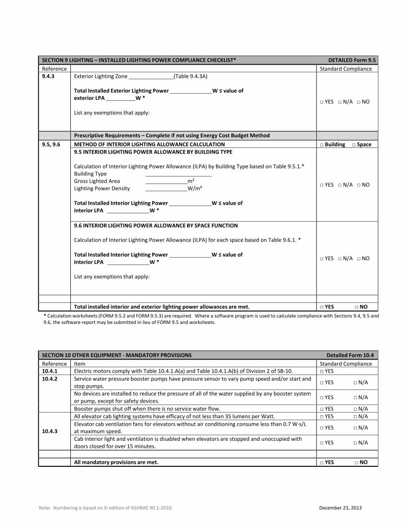
SECTION 9 LIGHTING – INSTALLED LIGHTING POWER COMPLIANCE CHECKLIST* DETAILED Form 9.5
Reference Standard Compliance
9.4.3 Exterior Lighting Zone (Table 9.4.3A)
Total Installed Exterior Lighting Power W ≤ value of
exterior LPA W *
List any exemptions that apply:
□ YES □ N/A □ NO
Prescriptive Requirements – Complete if not using Energy Cost Budget Method 9.5, 9.6 METHOD OF INTERIOR LIGHTING ALLOWANCE CALCULATION □ Building □ Space
9.5 INTERIOR LIGHTING POWER ALLOWANCE BY BUILDING TYPE
Calculation of Interior Lighting Power Allowance (ILPA) by Building Type based on Table 9.5.1.*
Building Type Gross Lighted Area m²
Lighting Power Density W/m²
Total Installed Interior Lighting Power W ≤ value of
interior LPA W *
□ YES □ N/A □ NO
9.6 INTERIOR LIGHTING POWER ALLOWANCE BY SPACE FUNCTION
Calculation of Interior Lighting Power Allowance (ILPA) for each space based on Table 9.6.1. *
Total Installed Interior Lighting Power W ≤ value of
Interior LPA W *
List any exemptions that apply:
□ YES □ N/A □ NO
Total installed interior and exterior lighting power allowances are met. □ YES □ NO
* Calculation worksheets (FORM 9.5.2 and FORM 9.5.3) are required. Where a software program is used to calculate compliance with Sections 9.4, 9.5 and
9.6, the software report may be submitted in lieu of FORM 9.5 and worksheets.
SECTION 10 OTHER EQUIPMENT ‐ MANDATORY PROVISIONS Detailed Form 10.4
Reference Item Standard Compliance
10.4.1 Electric motors comply with Table 10.4.1.A(a) and Table 10.4.1.A(b) of Division 2 of SB‐10. □ YES
10.4.2 Service water pressure booster pumps have pressure sensor to vary pump speed and/or start and
stop pumps.
□ YES □ N/A
No devices are installed to reduce the pressure of all of the water supplied by any booster system
or pump, except for safety devices.
□ YES □ N/A
Booster pumps shut off when there is no service water flow. □ YES □ N/A
10.4.3
All elevator cab lighting systems have efficacy of not less than 35 lumens per Watt. □ YES □ N/A
Elevator cab ventilation fans for elevators without air conditioning consume less than 0.7 W∙s/L
at maximum speed.
□ YES □ N/A
Cab interior light and ventilation is disabled when elevators are stopped and unoccupied with
doors closed for over 15 minutes.
□ YES □ N/A
All mandatory provisions are met. □ YES □ NO
Note: Numbering is based on SI edition of ASHRAE 90.1‐2010. December 23, 2013
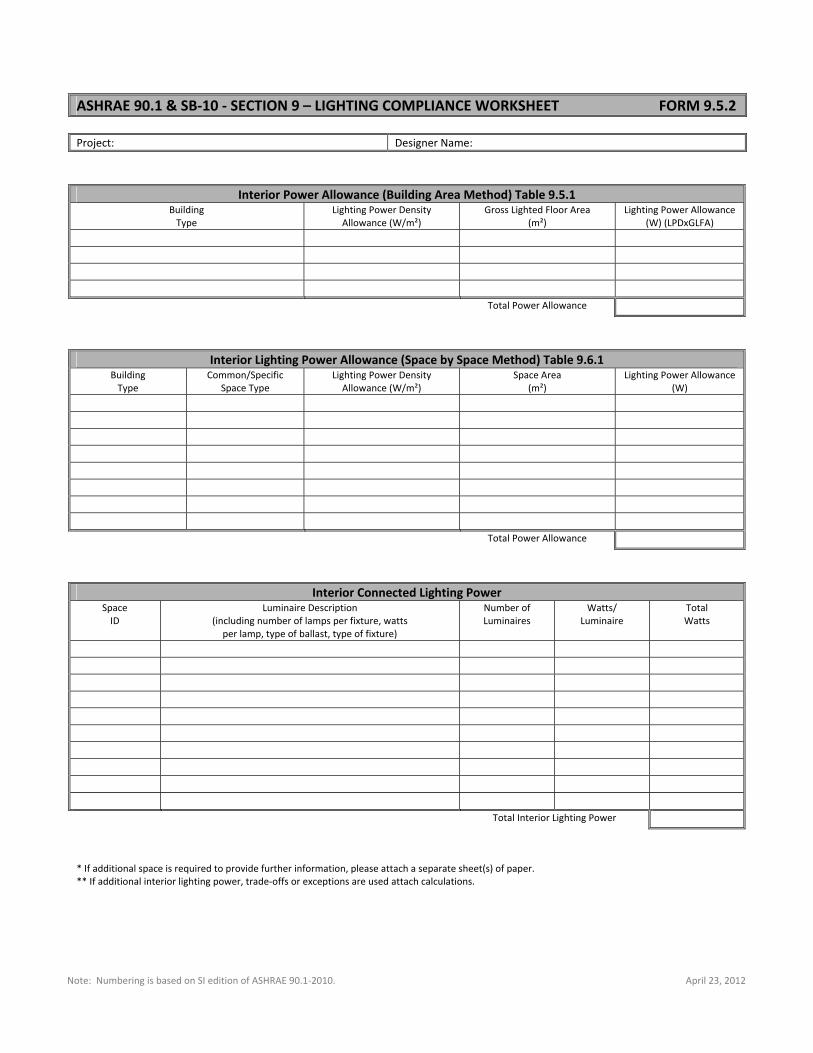
Note: Numbering is based on SI edition of ASHRAE 90.1‐2010. April 23, 2012
ASHRAE 90.1 & SB‐10 ‐ SECTION 9 – LIGHTING COMPLIANCE WORKSHEET FORM 9.5.2 Project: Designer Name:
Interior Power Allowance (Building Area Method) Table 9.5.1 Building Type
Lighting Power DensityAllowance (W/m²)
Gross Lighted Floor Area (m²)
Lighting Power Allowance(W) (LPDxGLFA)
Total Power Allowance
Interior Lighting Power Allowance (Space by Space Method) Table 9.6.1 Building Type
Common/Specific Space Type
Lighting Power DensityAllowance (W/m²)
Space Area(m²)
Lighting Power Allowance(W)
Total Power Allowance
Interior Connected Lighting Power Space ID
Luminaire Description(including number of lamps per fixture, watts per lamp, type of ballast, type of fixture)
Number of Luminaires
Watts/ Luminaire
TotalWatts
Total Interior Lighting Power
* If additional space is required to provide further information, please attach a separate sheet(s) of paper. ** If additional interior lighting power, trade‐offs or exceptions are used attach calculations.
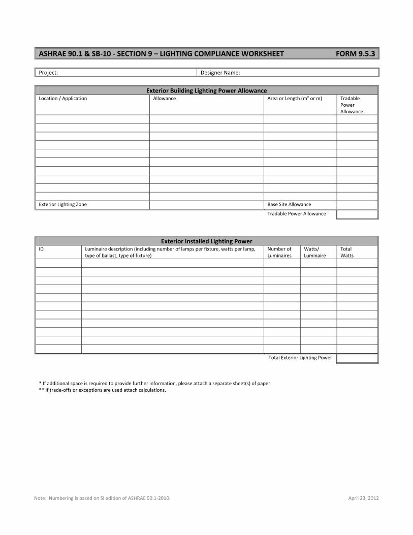
Note: Numbering is based on SI edition of ASHRAE 90.1‐2010. April 23, 2012
ASHRAE 90.1 & SB‐10 ‐ SECTION 9 – LIGHTING COMPLIANCE WORKSHEET FORM 9.5.3 Project: Designer Name:
Exterior Building Lighting Power Allowance Location / Application Allowance Area or Length (m² or m) Tradable
Power Allowance
Exterior Lighting Zone Base Site Allowance
Tradable Power Allowance
Exterior Installed Lighting Power ID Luminaire description (including number of lamps per fixture, watts per lamp,
type of ballast, type of fixture) Number of Luminaires
Watts/ Luminaire
TotalWatts
Total Exterior Lighting Power
* If additional space is required to provide further information, please attach a separate sheet(s) of paper. ** If trade‐offs or exceptions are used attach calculations.
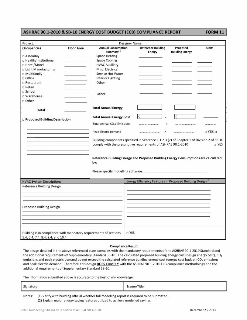
ASHRAE 90.1‐2010 & SB‐10 ENERGY COST BUDGET (ECB) COMPLIANCE REPORT FORM 11
Project: Designer Name:
Occupancies Floor Area
□ Assembly
□ Health/Institutional □ Hotel/Motel □ Light Manufacturing □ Multifamily □ Office
□ Restaurant □ Retail
□ School
□ Warehouse □ Other
Total
□ Proposed Building Description
__________________________________ __________________________________ __________________________________ __________________________________ __________________________________ __________________________________ __________________________________
Annual Consumption Reference Building Proposed Units
Summary(1)
Energy Building Energy
Space Heating Space Cooling HVAC Auxiliary Misc. Electrical Service Hot Water Interior Lighting Other
Other
Total Annual Energy
Total Annual Energy Cost $ > $
Total Annual CO2e Emissions ……………………… > ……………………….. …………….
Peak Electric Demand ……………………… > ……………………….. □ YES or
Building components specified in Sentence 1.1.2.3.(2) of Chapter 1 of Division 2 of SB-10
comply with the prescriptive requirements of ASHRAE 90.1-2010 □ YES
Reference Building Energy and Proposed Building Energy Consumptions are calculated
by:
Please specify modelling software:
HVAC System Descriptions Energy Efficiency Features in Proposed Building Design(2)
Reference Building Design
Proposed Building Design
Building is in compliance with mandatory requirements of sections
5.4, 6.4, 7.4, 8.4, 9.4, and 10.4
□ YES
Compliance Result
The design detailed in the above referenced plans complies with the mandatory requirements of the ASHRAE 90.1-2010 Standard and
the additional requirements of Supplementary Standard SB-10. The calculated proposed building energy cost (design energy cost), CO2
emissions and peak electric demand do not exceed the calculated reference building energy cost (energy cost budget) CO2 emissions
and peak electric demand. Therefore, this design DOES COMPLY with the ASHRAE 90.1-2010 ECB compliance methodology and the
additional requirements of Supplementary Standard SB-10.
The information submitted above is accurate to the best of my knowledge.
Signature: Name/Title:
Notes: (1) Verify with building official whether full modelling report is required to be submitted.
(2) Explain major energy saving features utilized to achieve modelled savings.
Note: Numbering is based on SI edition of ASHRAE 90.1-2010. December 23, 2013
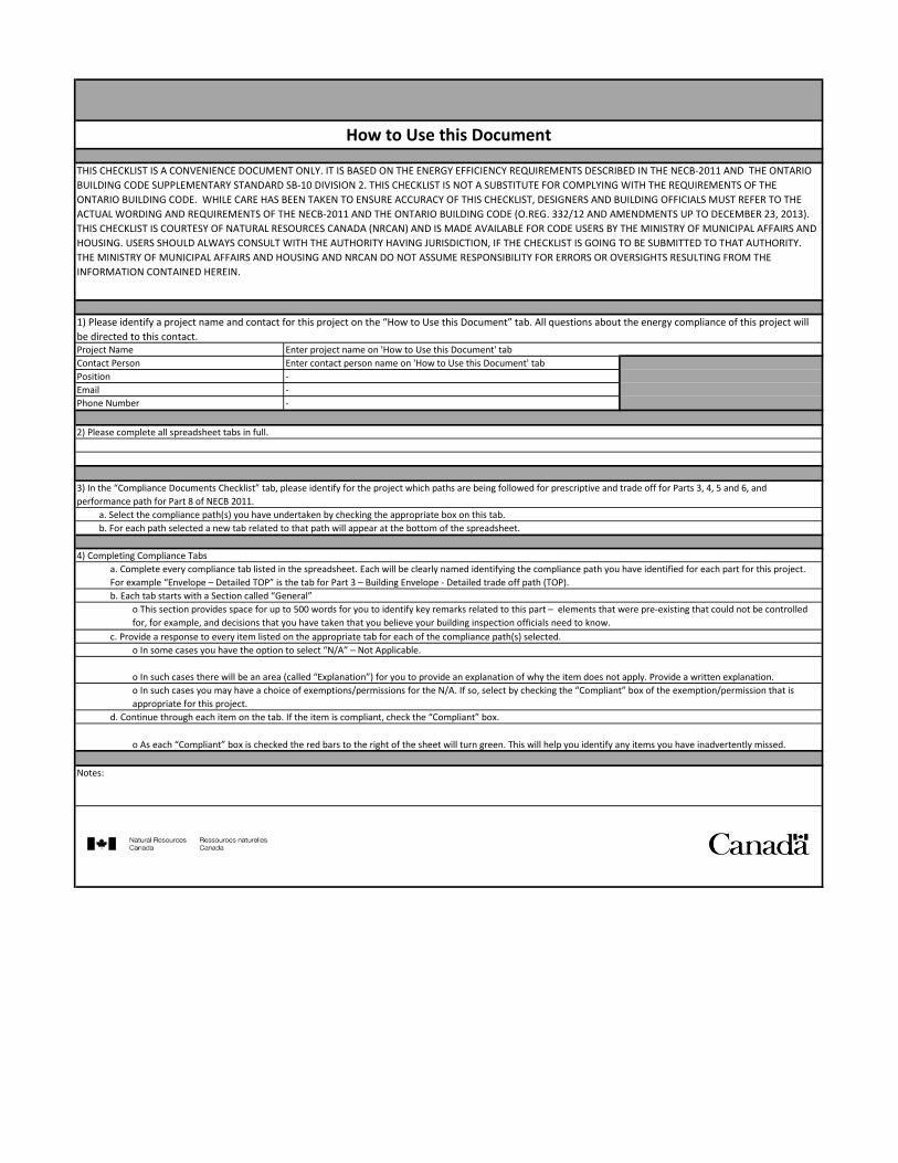
o In such cases you may have a choice of exemptions/permissions for the N/A. If so, select by checking the “Compliant” box of the exemption/permission that is
appropriate for this project.
d. Continue through each item on the tab. If the item is compliant, check the “Compliant” box.
o As each “Compliant” box is checked the red bars to the right of the sheet will turn green. This will help you identify any items you have inadvertently missed.
Notes:
a. Complete every compliance tab listed in the spreadsheet. Each will be clearly named identifying the compliance path you have identified for each part for this project.
For example “Envelope – Detailed TOP” is the tab for Part 3 – Building Envelope - Detailed trade off path (TOP).
b. Each tab starts with a Section called “General”
o This section provides space for up to 500 words for you to identify key remarks related to this part – elements that were pre-existing that could not be controlled
for, for example, and decisions that you have taken that you believe your building inspection officials need to know.
c. Provide a response to every item listed on the appropriate tab for each of the compliance path(s) selected.
o In some cases you have the option to select “N/A” – Not Applicable.
o In such cases there will be an area (called “Explanation”) for you to provide an explanation of why the item does not apply. Provide a written explanation.
3) In the “Compliance Documents Checklist” tab, please identify for the project which paths are being followed for prescriptive and trade off for Parts 3, 4, 5 and 6, and
performance path for Part 8 of NECB 2011.
a. Select the compliance path(s) you have undertaken by checking the appropriate box on this tab.
b. For each path selected a new tab related to that path will appear at the bottom of the spreadsheet.
4) Completing Compliance Tabs
Phone Number -
2) Please complete all spreadsheet tabs in full.
1) Please identify a project name and contact for this project on the “How to Use this Document” tab. All questions about the energy compliance of this project will
be directed to this contact. Project Name Enter project name on 'How to Use this Document' tab
Contact Person Enter contact person name on 'How to Use this Document' tab
Position -
Email -
How to Use this Document
THIS CHECKLIST IS A CONVENIENCE DOCUMENT ONLY. IT IS BASED ON THE ENERGY EFFICIENCY REQUIREMENTS DESCRIBED IN THE NECB-2011 AND THE ONTARIO
BUILDING CODE SUPPLEMENTARY STANDARD SB-10 DIVISION 2. THIS CHECKLIST IS NOT A SUBSTITUTE FOR COMPLYING WITH THE REQUIREMENTS OF THE
ONTARIO BUILDING CODE. WHILE CARE HAS BEEN TAKEN TO ENSURE ACCURACY OF THIS CHECKLIST, DESIGNERS AND BUILDING OFFICIALS MUST REFER TO THE
ACTUAL WORDING AND REQUIREMENTS OF THE NECB-2011 AND THE ONTARIO BUILDING CODE (O.REG. 332/12 AND AMENDMENTS UP TO DECEMBER 23, 2013).
THIS CHECKLIST IS COURTESY OF NATURAL RESOURCES CANADA (NRCAN) AND IS MADE AVAILABLE FOR CODE USERS BY THE MINISTRY OF MUNICIPAL AFFAIRS AND
HOUSING. USERS SHOULD ALWAYS CONSULT WITH THE AUTHORITY HAVING JURISDICTION, IF THE CHECKLIST IS GOING TO BE SUBMITTED TO THAT AUTHORITY.
THE MINISTRY OF MUNICIPAL AFFAIRS AND HOUSING AND NRCAN DO NOT ASSUME RESPONSIBILITY FOR ERRORS OR OVERSIGHTS RESULTING FROM THE
INFORMATION CONTAINED HEREIN.
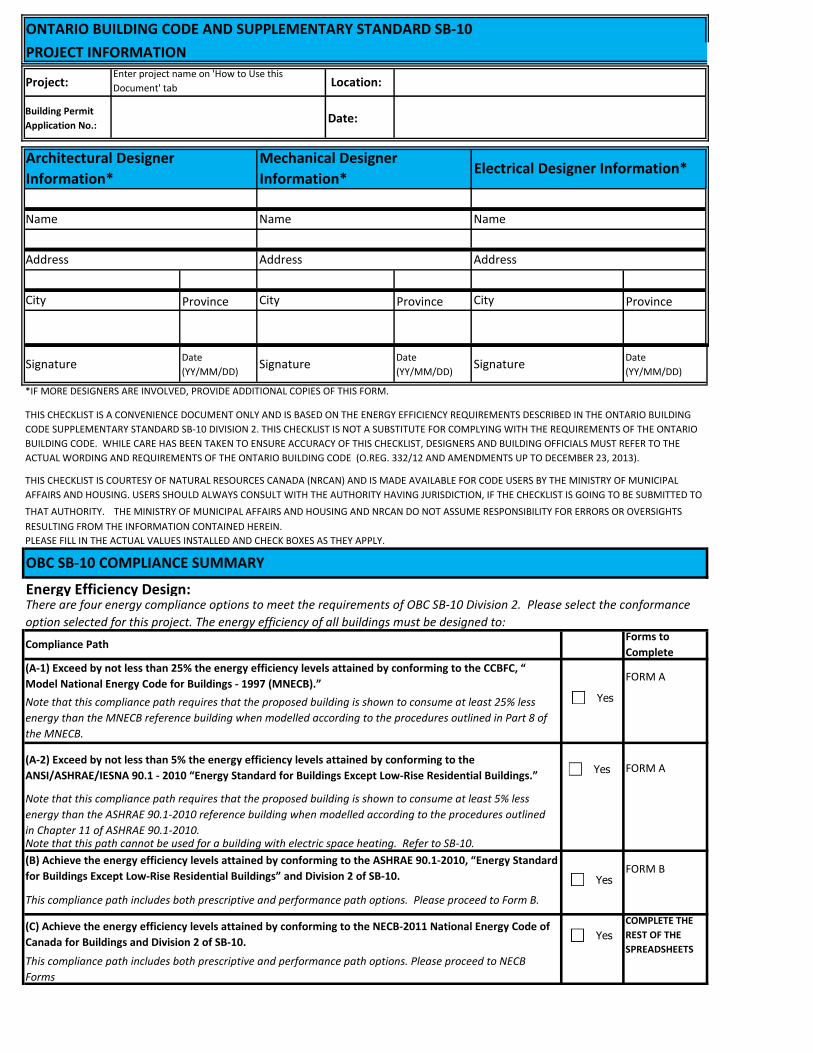
Project: Location:
Building Permit
Application No.: Date:
Province Province Province
Date
(YY/MM/DD)
Date
(YY/MM/DD)
Date
(YY/MM/DD)
FORM A
FORM A
FORM B
COMPLETE THE
REST OF THE
SPREADSHEETS
This compliance path includes both prescriptive and performance path options. Please proceed to Form B.
(C) Achieve the energy efficiency levels attained by conforming to the NECB-2011 National Energy Code of
Canada for Buildings and Division 2 of SB‐10.
This compliance path includes both prescriptive and performance path options. Please proceed to NECB
Forms
(A‐1) Exceed by not less than 25% the energy efficiency levels attained by conforming to the CCBFC, “
Model National Energy Code for Buildings ‐ 1997 (MNECB).”
Note that this compliance path requires that the proposed building is shown to consume at least 25% less
energy than the MNECB reference building when modelled according to the procedures outlined in Part 8 of
the MNECB.
(A-2) Exceed by not less than 5% the energy efficiency levels attained by conforming to the
ANSI/ASHRAE/IESNA 90.1 ‐ 2010 “Energy Standard for Buildings Except Low‐Rise Residential Buildings.”
Note that this compliance path requires that the proposed building is shown to consume at least 5% less
energy than the ASHRAE 90.1-2010 reference building when modelled according to the procedures outlined
in Chapter 11 of ASHRAE 90.1-2010.Note that this path cannot be used for a building with electric space heating. Refer to SB-10.
(B) Achieve the energy efficiency levels attained by conforming to the ASHRAE 90.1‐2010, “Energy Standard
for Buildings Except Low‐Rise Residential Buildings” and Division 2 of SB‐10.
PLEASE FILL IN THE ACTUAL VALUES INSTALLED AND CHECK BOXES AS THEY APPLY.
OBC SB-10 COMPLIANCE SUMMARY
Energy Efficiency Design:There are four energy compliance options to meet the requirements of OBC SB-10 Division 2. Please select the conformance
option selected for this project. The energy efficiency of all buildings must be designed to:
Compliance PathForms to
Complete
THIS CHECKLIST IS COURTESY OF NATURAL RESOURCES CANADA (NRCAN) AND IS MADE AVAILABLE FOR CODE USERS BY THE MINISTRY OF MUNICIPAL
AFFAIRS AND HOUSING. USERS SHOULD ALWAYS CONSULT WITH THE AUTHORITY HAVING JURISDICTION, IF THE CHECKLIST IS GOING TO BE SUBMITTED TO
THAT AUTHORITY. THE MINISTRY OF MUNICIPAL AFFAIRS AND HOUSING AND NRCAN DO NOT ASSUME RESPONSIBILITY FOR ERRORS OR OVERSIGHTS
RESULTING FROM THE INFORMATION CONTAINED HEREIN.
City City City
Signature Signature Signature
*IF MORE DESIGNERS ARE INVOLVED, PROVIDE ADDITIONAL COPIES OF THIS FORM.
THIS CHECKLIST IS A CONVENIENCE DOCUMENT ONLY AND IS BASED ON THE ENERGY EFFICIENCY REQUIREMENTS DESCRIBED IN THE ONTARIO BUILDING
CODE SUPPLEMENTARY STANDARD SB-10 DIVISION 2. THIS CHECKLIST IS NOT A SUBSTITUTE FOR COMPLYING WITH THE REQUIREMENTS OF THE ONTARIO
BUILDING CODE. WHILE CARE HAS BEEN TAKEN TO ENSURE ACCURACY OF THIS CHECKLIST, DESIGNERS AND BUILDING OFFICIALS MUST REFER TO THE
ACTUAL WORDING AND REQUIREMENTS OF THE ONTARIO BUILDING CODE (O.REG. 332/12 AND AMENDMENTS UP TO DECEMBER 23, 2013).
Address Address Address
Name Name Name
Architectural Designer
Information*
Mechanical Designer
Information*Electrical Designer Information*
ONTARIO BUILDING CODE AND SUPPLEMENTARY STANDARD SB-10
PROJECT INFORMATION Enter project name on 'How to Use this
Document' tab
Yes
Yes
Yes
Yes
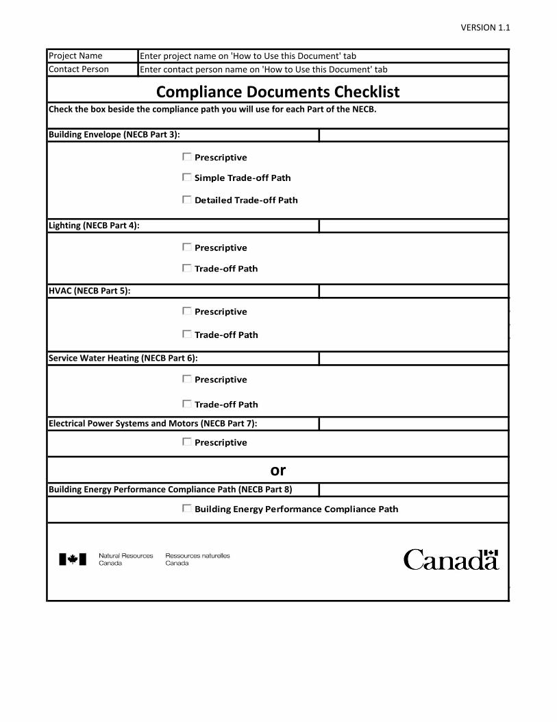
VERSION 1.1
Service Water Heating (NECB Part 6):
Electrical Power Systems and Motors (NECB Part 7):
Building Energy Performance Compliance Path (NECB Part 8)
Compliance Documents Checklist
or
Check the box beside the compliance path you will use for each Part of the NECB.
Enter contact person name on 'How to Use this Document' tab
Project Name Enter project name on 'How to Use this Document' tab
Contact Person
HVAC (NECB Part 5):
Lighting (NECB Part 4):
Building Envelope (NECB Part 3):
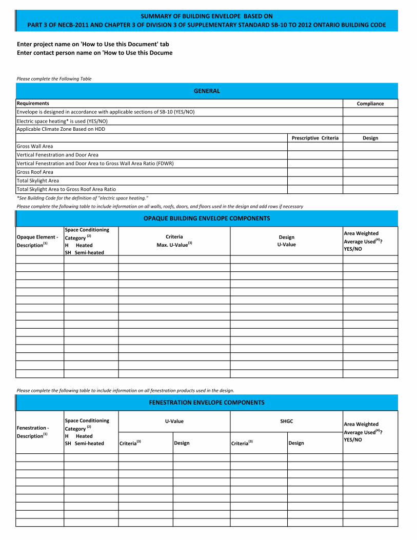
Please complete the Following Table
Compliance
Prescriptive Criteria Design
*See Building Code for the definition of "electric space heating."
Please complete the following table to include information on all walls, roofs, doors, and floors used in the design and add rows if necessary
Opaque Element -
Description(1)
Space Conditioning
Category (2)
H Heated
SH Semi-heated
Area Weighted
Average Used(4)?
YES/NO
Please complete the following table to include information on all fenestration products used in the design.
Criteria(3) Design Criteria(3) Design
FENESTRATION ENVELOPE COMPONENTS
Fenestration -
Description(1)
Space Conditioning
Category (2)
H Heated
SH Semi-heated
U-Value SHGCArea Weighted
Average Used(4)?
YES/NO
Total Skylight Area to Gross Roof Area Ratio
OPAQUE BUILDING ENVELOPE COMPONENTS
Criteria
Max. U-Value(3)
Design
U-Value
Total Skylight Area
SUMMARY OF BUILDING ENVELOPE BASED ON
PART 3 OF NECB-2011 AND CHAPTER 3 OF DIVISION 3 OF SUPPLEMENTARY STANDARD SB-10 TO 2012 ONTARIO BUILDING CODE
GENERAL
Requirements
Envelope is designed in accordance with applicable sections of SB-10 (YES/NO)
Electric space heating* is used (YES/NO)
Applicable Climate Zone Based on HDD
Gross Wall Area
Vertical Fenestration and Door Area
Vertical Fenestration and Door Area to Gross Wall Area Ratio (FDWR)
Gross Roof Area
Enter project name on 'How to Use this Document' tab
Enter contact person name on 'How to Use this Document' tab

(1) Indicate if Element is a Wall, Roof, Floor, Door, Window or Skylight and a Tag or Description (eg Wall – W1).
(2) Enter Use: Heated (H) or Semiheated (SH).
(3) Enter the U-value required from Table 3.2.2.2. to 3.2.3.1. and Chapter 2 of Division 2 of SB-10
(4) Elements of the same type, space category, and class of construction can be averaged using area weighting to show compliance.
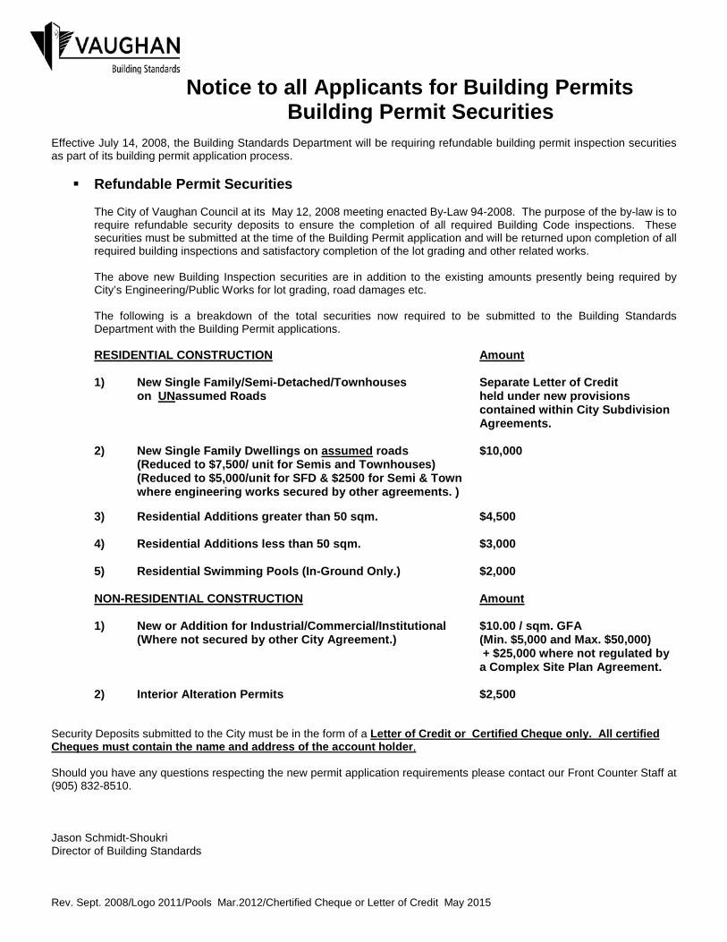
Effective July 14, 2008, the Building Standards Department will be requiring refundable building permit inspection securities as part of its building permit application process. Refundable Permit Securities
The City of Vaughan Council at its May 12, 2008 meeting enacted By-Law 94-2008. The purpose of the by-law is to require refundable security deposits to ensure the completion of all required Building Code inspections. These securities must be submitted at the time of the Building Permit application and will be returned upon completion of all required building inspections and satisfactory completion of the lot grading and other related works. The above new Building Inspection securities are in addition to the existing amounts presently being required by City’s Engineering/Public Works for lot grading, road damages etc. The following is a breakdown of the total securities now required to be submitted to the Building Standards Department with the Building Permit applications.
RESIDENTIAL CONSTRUCTION Amount
1) New Single Family/Semi-Detached/Townhouses Separate Letter of Credit on UNassumed Roads held under new provisions
contained within City Subdivision Agreements.
2) New Single Family Dwellings on assumed roads $10,000 (Reduced to $7,500/ unit for Semis and Townhouses) (Reduced to $5,000/unit for SFD & $2500 for Semi & Town where engineering works secured by other agreements. ) 3) Residential Additions greater than 50 sqm. $4,500 4) Residential Additions less than 50 sqm. $3,000 5) Residential Swimming Pools (In-Ground Only.) $2,000 NON-RESIDENTIAL CONSTRUCTION Amount 1) New or Addition for Industrial/Commercial/Institutional $10.00 / sqm. GFA (Where not secured by other City Agreement.) (Min. $5,000 and Max. $50,000)
+ $25,000 where not regulated by a Complex Site Plan Agreement.
2) Interior Alteration Permits $2,500
Security Deposits submitted to the City must be in the form of a Letter of Credit or Certified Cheque only. All certified Cheques must contain the name and address of the account holder, Should you have any questions respecting the new permit application requirements please contact our Front Counter Staff at (905) 832-8510. Jason Schmidt-Shoukri Director of Building Standards Rev. Sept. 2008/Logo 2011/Pools Mar.2012/Chertified Cheque or Letter of Credit May 2015
Notice to all Applicants for Building Permits Building Permit Securities