Embed Size (px)
Citation preview

Newnes Data Communications Pocket Book

NewnesData CommunicationsPocket BookFourth edition
Michael TooleySteve Winder
OXFORD AMSTERDAM BOSTON LONDON NEW YORK PARISSAN DIEGO SAN FRANCISCO SINGAPORE SYDNEY TOKYO

NewnesAn imprint of Elsevier ScienceLinacre House, Jordan Hill, Oxford OX2 8DP225 Wildwood Avenue, Woburn, MA 01801-2041
First published 1989Reprinted 1990Second edition 1992Reprinted 1993, 1994, 1995Third edition 1997Reprinted 1998 (twice), 1999Fourth edition 2002
Copyright Steve Winder and Mike Tooley, 1989, 1992, 1997, 2002.All rights reserved
No part of this publicationmay be reproduced in any material form (includingphotocopying or storing in any medium by electronicmeans and whether or not transiently or incidentallyto some other use of this publication) without thewritten permission of the copyright holder exceptin accordance with the provisions of the Copyright,Designs and Patents Act 1988 or under the terms of alicence issued by the Copyright Licensing Agency Ltd,90 Tottenham Court Road, London, England W1P 4LP.Applications for the copyright holder’s written permissionto reproduce any part of this publication should be addressedto the publishers
British Library Cataloguing in Publication DataA catalogue record for this book is available from the British Library
ISBN 0 7506 52977
For information on all Newnes publications visit our website atwww.newnespress.com
Typeset by Laserwords Private Limited, Chennai, IndiaPrinted and bound in Great Britain
Contents
Preface vii
1 Glossary 12 Terminals 373 Transmission media 484 Serial interfaces 685 Data communication equipment 1036 Parallel interfaces 1307 Communication protocols 1468 Local area networks 1499 Wide area networks 175
10 Transmission protocols 18211 Reference information 212
Index 241
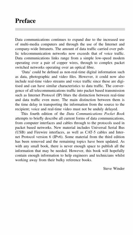
Preface
Data communications continues to expand due to the increased useof multi-media computers and through the use of the Internet andcompany-wide Intranets. The amount of data traffic carried over pub-lic telecommunication networks now exceeds that of voice traffic.Data communications links range from a simple low-speed modemoperating over a pair of copper wires, through to complex packetswitched networks operating over an optical fibre.
‘Data’ could be defined as non-real-time digital information suchas data, photographic and video files. However, it could now alsoinclude real-time video streams and voice traffic since these are digi-tised and can have similar characteristics to data traffic. The conver-gence of all telecommunications traffic into packet based transmissionsuch as Internet Protocol (IP) blurs the distinction between real-timeand data traffic even more. The main distinction between them isthe time delay in transporting the information from the source to therecipient; voice and real-time video must not be unduly delayed.
This fourth edition of the Data Communications Pocket Bookattempts to briefly describe all current forms of data communications,from computer interfaces and cables through to the protocols used inpacket based networks. New material includes Universal Serial Bus(USB) and Firewire interfaces, as well as CAT-5 cables and Inter-net Protocol version 6 (IPv6). Some material from the third editionhas been removed and the remaining topics have been updated. Aswith any small book, there is never enough space to publish all theinformation that may be needed. However, this book will hopefullycontain enough information to help engineers and technicians whilstworking away from their bulky reference books.
Steve Winder
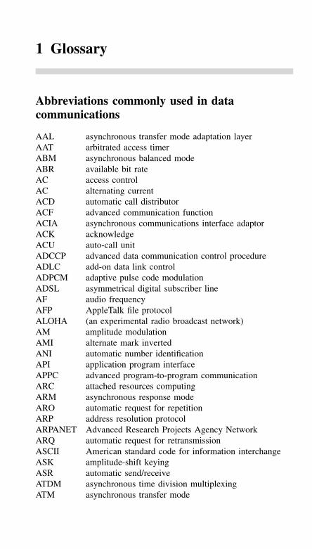
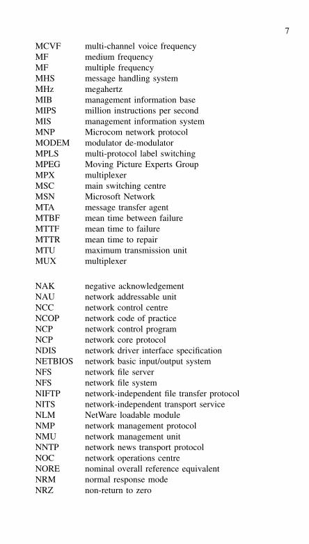
1 Glossary
Abbreviations commonly used in datacommunications
AAL asynchronous transfer mode adaptation layerAAT arbitrated access timerABM asynchronous balanced modeABR available bit rateAC access controlAC alternating currentACD automatic call distributorACF advanced communication functionACIA asynchronous communications interface adaptorACK acknowledgeACU auto-call unitADCCP advanced data communication control procedureADLC add-on data link controlADPCM adaptive pulse code modulationADSL asymmetrical digital subscriber lineAF audio frequencyAFP AppleTalk file protocolALOHA (an experimental radio broadcast network)AM amplitude modulationAMI alternate mark invertedANI automatic number identificationAPI application program interfaceAPPC advanced program-to-program communicationARC attached resources computingARM asynchronous response modeARO automatic request for repetitionARP address resolution protocolARPANET Advanced Research Projects Agency NetworkARQ automatic request for retransmissionASCII American standard code for information interchangeASK amplitude-shift keyingASR automatic send/receiveATDM asynchronous time division multiplexingATM asynchronous transfer mode
2
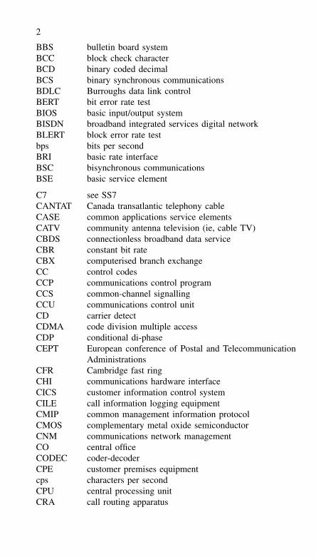
BBS bulletin board systemBCC block check characterBCD binary coded decimalBCS binary synchronous communicationsBDLC Burroughs data link controlBERT bit error rate testBIOS basic input/output systemBISDN broadband integrated services digital networkBLERT block error rate testbps bits per secondBRI basic rate interfaceBSC bisynchronous communicationsBSE basic service element
C7 see SS7CANTAT Canada transatlantic telephony cableCASE common applications service elementsCATV community antenna television (ie, cable TV)CBDS connectionless broadband data serviceCBR constant bit rateCBX computerised branch exchangeCC control codesCCP communications control programCCS common-channel signallingCCU communications control unitCD carrier detectCDMA code division multiple accessCDP conditional di-phaseCEPT European conference of Postal and Telecommunication
AdministrationsCFR Cambridge fast ringCHI communications hardware interfaceCICS customer information control systemCILE call information logging equipmentCMIP common management information protocolCMOS complementary metal oxide semiconductorCNM communications network managementCO central officeCODEC coder-decoderCPE customer premises equipmentcps characters per secondCPU central processing unitCRA call routing apparatus
3
CRC cyclic redundancy checkCRT cathode ray tubeCSMA carrier sense multiple accessCSMA/CA CSMA with collision avoidanceCSMA/CD CSMA with collision detectionCSPCN circuit-switched public data networkCSU channel service unitCTA circuit terminating equipmentCTS clear to sendCUG closed user groupCVSD continuously variable slope delta modulation
DA destination addressDAA data access arrangementDACS digital access and cross-connect systemDART dual asynchronous receiver/transmitterDASS digital access signalling systemdB decibeldBm decibels relative to a reference level of 1 mWDC direct currentDCD data and carrier detectDCE data circuit-terminating equipmentDCE data communications equipmentDDCMP digital data communication message protocolDDD direct distance diallingDDI direct dial-inDDN digital data networkDDS Dataphone digital servicesDDS digital data serviceDEA data encryption algorithmDECT digital European cordless telephoneDES data encryption standardDID direct inward diallingDNIC data network identification codeDOV data over voiceDPNSS digital private network signalling systemDPSK differential phase-shift keyingDQDB distributed queue dual busDRS data rate selectDSA distributed systems architectureDSB double sidebandDSBSC double sideband suppressed carrierDSC district switching centre
4
DSL digital subscriber lineDSLAM digital subscriber line access multiplexerDSU digital service unitDTE data terminal equipmentDTMF dual tone multi-frequencyDTR data terminal readyDUP data user partDXI data exchange interface
EBCDIC extended binary coded decimal interchange codeEBX electronic branch exchangeED ending delimiterEDI electronic data interchangeEDU error detecting unitEFT electronic funds transferEISA extended industry standard architectureELR earthed loopEMA enterprise management architectureEMC electromagnetic compatibilityEMI electromagnetic interferenceENQ enquiryEOT end of transmissionEPoS electronic point of saleEPSS experimental packet switching serviceESF extended superframe formatETB end of transmitted blockETS European Telecommunications StandardETX end of text
FAX facsimileFC frame controlFCS frame check sequenceFDDI fibre distributed data interfaceFDM frequency division multiplexingFE format effectorsFEC forward error controlFEP front end processorFIFO first-in, first-out (memory)FM frequency modulationFS frame statusFSK frequency-shift keyingFTAM file transfer access and managementFTP file transfer protocol
5
FTTC Fibre to the curbFTTH Fibre to the homeFXO foreign exchange officeFXS foreign exchange subscriber
GHz 109 HzGND groundGOSIP Government OSI profileGSC group switching centreGSM global system for mobileGUI graphical user interface
HDB3 high-density bipolar code no. 3HDLC high-level data link controlHDSL high bit rate digital subscriber lineHDTV high-definition televisionHF high frequencyHM hybrid modulationHSLN high-speed local networkHTML hypertext mark-up languageHz Hertz (cycles per second)
IA5 international alphabet no. 5ICMP Internet control message protocolICP interconnection protocolIDA integrated digital accessIDD international direct diallingIDN integrated digital networkIEC inter-exchange carrierILD injector laser diodeILEC incumbert local exchange carrierIMP interface message processorINFO informationI/O input/outputIOT inter-office trunkIP Internet protocolIPMS interpersonal message processorIPSS international packet-switched serviceIPX Internet packet exchangeIRQ interrupt requestIS information separatorISD international subscriber diallingISDN integrated services digital network
6
ISN information systems networkISP Internet service providerISPBX integrated services private automatic branch exchangeIT information technologyITA2 international telegraph alphabet no. 2ITC independent telephone companyITU International Telecommunications UnionIVDT integrated voice and data terminal
JPEG Joint Photographic Experts GroupJTMP joint transfer and manipulation protocol
kHz kilohertzKTS key telephone system
LAM line adaptor moduleLAN local area networkLAP link access protocolLAPB link access protocol balancedLAPM link access procedure for modemsLAT local area transportLATA local access and transport areaLCD liquid crystal displayLD loop disconnectLDM limited distance modemLEC local exchange carrierLED light emitting diodeLEO low earth orbitLF low frequencyLLC logical link controlLMDS local multipoint distribution serviceLRC longitudinal redundancy checkLSB lower sidebandLSI large scale integrationLT line terminationLTE line terminating equipmentLU logical unitLWT listen while talk
MAC medium access controlMAN metropolitan area networkMAP manufacturing automation protocolMAU multi-station access unitMCA micro-channel architecture
7
MCVF multi-channel voice frequencyMF medium frequencyMF multiple frequencyMHS message handling systemMHz megahertzMIB management information baseMIPS million instructions per secondMIS management information systemMNP Microcom network protocolMODEM modulator de-modulatorMPLS multi-protocol label switchingMPEG Moving Picture Experts GroupMPX multiplexerMSC main switching centreMSN Microsoft NetworkMTA message transfer agentMTBF mean time between failureMTTF mean time to failureMTTR mean time to repairMTU maximum transmission unitMUX multiplexer
NAK negative acknowledgementNAU network addressable unitNCC network control centreNCOP network code of practiceNCP network control programNCP network core protocolNDIS network driver interface specificationNETBIOS network basic input/output systemNFS network file serverNFS network file systemNIFTP network-independent file transfer protocolNITS network-independent transport serviceNLM NetWare loadable moduleNMP network management protocolNMU network management unitNNTP network news transport protocolNOC network operations centreNORE nominal overall reference equivalentNRM normal response modeNRZ non-return to zero
8
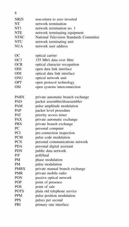
NRZI non-return to zero invertedNT network terminationNT1 network termination no. 1NTE network terminating equipmentNTSC National Television Standards CommitteeNTU network terminating unitNUA network user address
OC optical carrierOC3 155 Mb/s data over fibreOCR optical character recognitionODI open data link interfaceODI optical data link interfaceONU optical network unitOPT open protocol technologyOSI open systems interconnection
PABX private automatic branch exchangePAD packet assembler/disassemblerPAM pulse amplitude modulationPAP packet level procedurePAT priority access timerPAX private automatic exchangePBX private branch exchangePC personal computerPCI pre-connection inspectionPCM pulse code modulationPCN personal communications networkPDA personal digital assistantPDN public data networkP/F poll/finalPM phase modulationPM pulse modulationPMBX private manual branch exchangePMR private mobile radioPON passive optical networkPOP point of presencePOS point of salePOTS plain old telephone servicePPM pulse position modulationPPS pulses per secondPRI primary rate interface
9
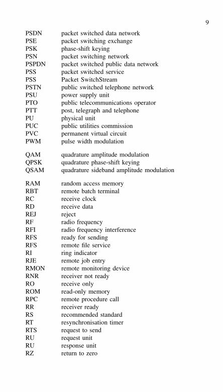
PSDN packet switched data networkPSE packet switching exchangePSK phase-shift keyingPSN packet switching networkPSPDN packet switched public data networkPSS packet switched servicePSS Packet SwitchStreamPSTN public switched telephone networkPSU power supply unitPTO public telecommunications operatorPTT post, telegraph and telephonePU physical unitPUC public utilities commissionPVC permanent virtual circuitPWM pulse width modulation
QAM quadrature amplitude modulationQPSK quadrature phase-shift keyingQSAM quadrature sideband amplitude modulation
RAM random access memoryRBT remote batch terminalRC receive clockRD receive dataREJ rejectRF radio frequencyRFI radio frequency interferenceRFS ready for sendingRFS remote file serviceRI ring indicatorRJE remote job entryRMON remote monitoring deviceRNR receiver not readyRO receive onlyROM read-only memoryRPC remote procedure callRR receiver readyRS recommended standardRT resynchronisation timerRTS request to sendRU request unitRU response unitRZ return to zero
10
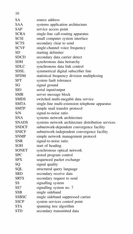
SA source addressSAA systems application architectureSAP service access pointSCRA single-line call-routing apparatusSCSI small computer system interfaceSCTS secondary clear to sendSCVF single-channel voice frequencySD starting delimiterSDCD secondary data carrier detectSDH synchronous data heirarchySDLC synchronous data link controlSDSL symmetrical digital subscriber lineSFDM statistical frequency division multiplexingSFT system fault toleranceSG signal groundSIO serial input/outputSMB server message blockSMDS switched multi-megabit data serviceSMTA single-line multi-extension telephone apparatusSMTP simple mail transfer protocolS/N signal-to-noise ratioSNA systems network architectureSNADS systems network architecture distribution servicesSNDCF subnetwork-dependent convergence facilitySNICF subnetwork-independent convergence facilitySNMP simple network management protocolSNR signal-to-noise ratioSOH start of headingSONET synchronous optical networkSPC stored program controlSPX sequenced packet exchangeSQ signal qualitySQL structured query languageSRD secondary receive dataSRTS secondary request to sendSS signalling systemSS7 signalling system no. 7SSB single sidebandSSBSC single sideband suppressed carrierSSCP system services control pointSTA spanning tree algorithmSTD secondary transmitted data
11
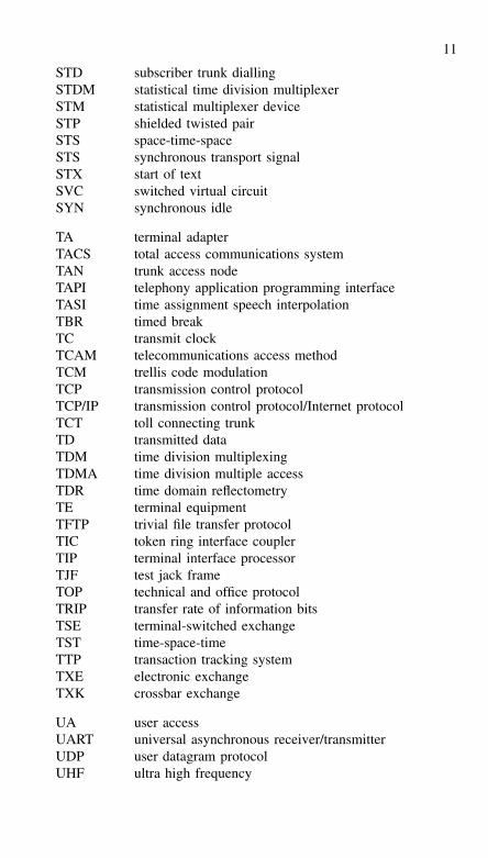
STD subscriber trunk diallingSTDM statistical time division multiplexerSTM statistical multiplexer deviceSTP shielded twisted pairSTS space-time-spaceSTS synchronous transport signalSTX start of textSVC switched virtual circuitSYN synchronous idle
TA terminal adapterTACS total access communications systemTAN trunk access nodeTAPI telephony application programming interfaceTASI time assignment speech interpolationTBR timed breakTC transmit clockTCAM telecommunications access methodTCM trellis code modulationTCP transmission control protocolTCP/IP transmission control protocol/Internet protocolTCT toll connecting trunkTD transmitted dataTDM time division multiplexingTDMA time division multiple accessTDR time domain reflectometryTE terminal equipmentTFTP trivial file transfer protocolTIC token ring interface couplerTIP terminal interface processorTJF test jack frameTOP technical and office protocolTRIP transfer rate of information bitsTSE terminal-switched exchangeTST time-space-timeTTP transaction tracking systemTXE electronic exchangeTXK crossbar exchange
UA user accessUART universal asynchronous receiver/transmitterUDP user datagram protocolUHF ultra high frequency
12
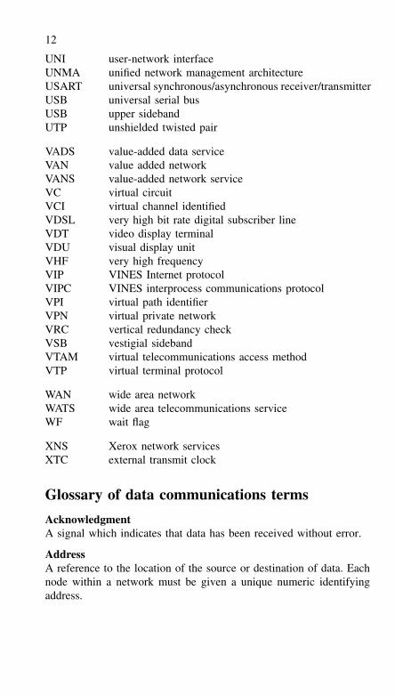
UNI user-network interfaceUNMA unified network management architectureUSART universal synchronous/asynchronous receiver/transmitterUSB universal serial busUSB upper sidebandUTP unshielded twisted pair
VADS value-added data serviceVAN value added networkVANS value-added network serviceVC virtual circuitVCI virtual channel identifiedVDSL very high bit rate digital subscriber lineVDT video display terminalVDU visual display unitVHF very high frequencyVIP VINES Internet protocolVIPC VINES interprocess communications protocolVPI virtual path identifierVPN virtual private networkVRC vertical redundancy checkVSB vestigial sidebandVTAM virtual telecommunications access methodVTP virtual terminal protocol
WAN wide area networkWATS wide area telecommunications serviceWF wait flag
XNS Xerox network servicesXTC external transmit clock
Glossary of data communications terms
AcknowledgmentA signal which indicates that data has been received without error.
AddressA reference to the location of the source or destination of data. Eachnode within a network must be given a unique numeric identifyingaddress.
13
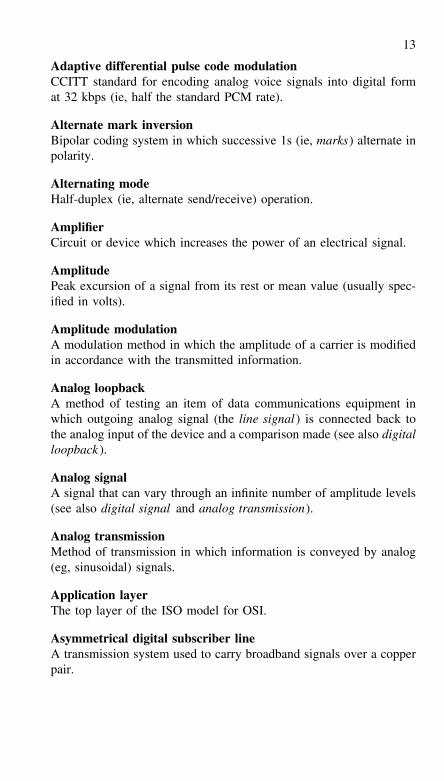
Adaptive differential pulse code modulationCCITT standard for encoding analog voice signals into digital format 32 kbps (ie, half the standard PCM rate).
Alternate mark inversionBipolar coding system in which successive 1s (ie, marks) alternate inpolarity.
Alternating modeHalf-duplex (ie, alternate send/receive) operation.
AmplifierCircuit or device which increases the power of an electrical signal.
AmplitudePeak excursion of a signal from its rest or mean value (usually spec-ified in volts).
Amplitude modulationA modulation method in which the amplitude of a carrier is modifiedin accordance with the transmitted information.
Analog loopbackA method of testing an item of data communications equipment inwhich outgoing analog signal (the line signal ) is connected back tothe analog input of the device and a comparison made (see also digitalloopback ).
Analog signalA signal that can vary through an infinite number of amplitude levels(see also digital signal and analog transmission).
Analog transmissionMethod of transmission in which information is conveyed by analog(eg, sinusoidal) signals.
Application layerThe top layer of the ISO model for OSI.
Asymmetrical digital subscriber lineA transmission system used to carry broadband signals over a copperpair.
14
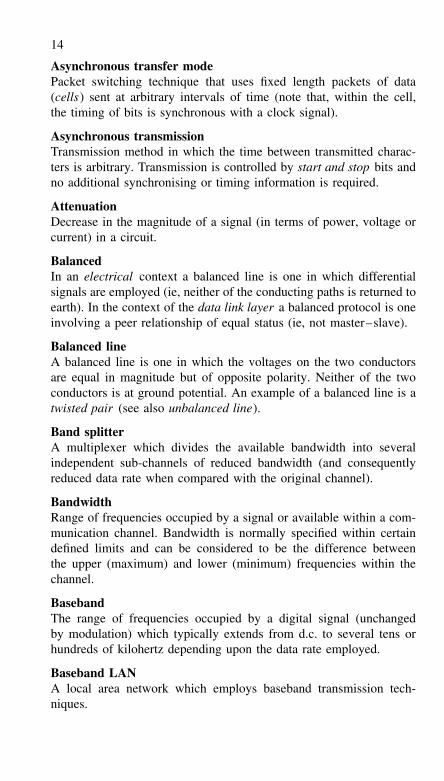
Asynchronous transfer modePacket switching technique that uses fixed length packets of data(cells) sent at arbitrary intervals of time (note that, within the cell,the timing of bits is synchronous with a clock signal).
Asynchronous transmissionTransmission method in which the time between transmitted charac-ters is arbitrary. Transmission is controlled by start and stop bits andno additional synchronising or timing information is required.
AttenuationDecrease in the magnitude of a signal (in terms of power, voltage orcurrent) in a circuit.
BalancedIn an electrical context a balanced line is one in which differentialsignals are employed (ie, neither of the conducting paths is returned toearth). In the context of the data link layer a balanced protocol is oneinvolving a peer relationship of equal status (ie, not master–slave).
Balanced lineA balanced line is one in which the voltages on the two conductorsare equal in magnitude but of opposite polarity. Neither of the twoconductors is at ground potential. An example of a balanced line is atwisted pair (see also unbalanced line).
Band splitterA multiplexer which divides the available bandwidth into severalindependent sub-channels of reduced bandwidth (and consequentlyreduced data rate when compared with the original channel).
BandwidthRange of frequencies occupied by a signal or available within a com-munication channel. Bandwidth is normally specified within certaindefined limits and can be considered to be the difference betweenthe upper (maximum) and lower (minimum) frequencies within thechannel.
BasebandThe range of frequencies occupied by a digital signal (unchangedby modulation) which typically extends from d.c. to several tens orhundreds of kilohertz depending upon the data rate employed.
Baseband LANA local area network which employs baseband transmission tech-niques.
15
Baseband transmissionTransmission method in which digital signals are passed, without mod-ulation, directly through the transmission medium.
BaudA unit of signalling speed expressed in terms of the number of signalevents per second.
Baud rateSignalling rate (note that this is not necessarily the same as the numberof bits transmitted per second).
Baudot codeA code used for data transmission in which each character is repre-sented by five bits. Shift characters are used so that a full set of upperand lower case letters, figures and punctuation cannot be transmitted.
Binary synchronous communicationIBM Communication protocol which employs a defined set of controlcharacters and control sequences for synchronised transmission ofbinary coded data (often referred to as bisync).
BitA contraction of ‘binary digit’; a single digit in a binary number.
Bit error rateA measure of the number of errors produced in a data communicationssystems. Bit error rate is usually expressed in terms of the ratio oferroneous bits to received bits (eg, 1 in 2 × 104 bits).
Bit rateThe rate at which bits are transmitted expressed in bits per sec-ond (bps).
BlockA contiguous sequence of data characters transmitted as one unit.Additional characters or codes may be added to the block to permitflow control (eg, synchronisation and error detection).
Block check characterA character tagged to the end of a block which provides a means ofverifying that the block has been received without error. The characteris derived from a predefined algorithm.
BlockingIn the context of PBX, blocking refers to an inability to provide aconnection path. In the context of the data link layer of the ISO
16
model for OSI, blocking refers to the combination of serial blocksinto one frame.
BluetoothA short range radio transmission system used to provide wirelessconnections to computer peripherals.
BreakA request to terminate transmission.
BroadbandA range of frequencies which is sufficiently wide to accommodate one(or more) carriers modulated by digital information, typically severaltens of kilohertz to several tens of megahertz.
Broadband integrated services digital networkAn integrated services digital network (ISDN) that is designed tocarry digital data, voice and video (see also integrated services digi-tal network ). Asynchronous transfer mode is used to provide packetswitching in conjunction with optical fibres and associated high-speeddata transmission equipment.
Broadband LANA local area network which employs broadband transmission tech-niques.
Broadband transmissionTransmission method in which a carrier is modulated by a signal priorto being passed through the transmission medium (eg, coaxial cable).Broadband transmission allows several signals to be present within asingle transmission medium using frequency division multiplexing.
BufferIn a hardware context, a buffer is a device which provides a degree ofelectrical isolation at an interface (the input to a buffer usually exhibitsa much higher impedance than its output). In a software context, abuffer is a reserved area of memory which provides temporary datastorage and thus may be used to compensate for a difference in therate of data flow or time of occurrence of events.
Burst errorsA form of error in which several consecutive bits within the transmit-ted signal are erroneous.
BusA signal path which is invariably shared by a number of signals.
17
ByteA group of binary digits (bits) which is operated on as a unit. A bytenormally comprises eight bits and thus can be used to represent acharacter.
CableA transmission medium in which signals are passed along electricalconductors (often coaxial).
CarrierA signal (usually sinusoidal) upon which information is modulated.
Carrier senseThe ability of a node to detect traffic present within a channel.
Carrier sense multiple accessA protocol method which involves listening on a channel before send-ing. This technique allows a number of nodes to share a commontransmission channel.
Central officeA telephone exchange for switching circuits.
ChannelA path between two or more points which allows data communica-tions to take place. Channels are often derived by multiplexing andthere need not be a one-to-one correspondence between channels andphysical circuits.
CharacterA single letter, figure, punctuation symbol, or control code. Usuallyrepresented by either seven or eight bits.
ChecksumA form of error checking in which the sum of all data bytes withina block is formed (any carry generated is usually discarded) and thenappended to the transmitted block.
CircuitAn electrical connection comprising two (a two-wire circuit) or fourwires (a four-wire circuit).
Circuit switchingA conventional form of switched interconnection in which a two-waycircuit is provided for exclusive use during the period of connection.
ClearAct of closing a connection.
18
ClockA source of timing or synchronising signals.
CloseAct of terminating a connection.
Coaxial cableA form of cable in which two concentric conductors are employed.The inner conductor is completely surrounded by (but electricallyinsulated from) the outer conductor. Coaxial cable is commonly usedfor both baseband and broadband LANS.
CollisionA conflict within the transmission path which is caused by two ormore nodes sending information at the same time.
Collision avoidanceA technique used to avoid contention in which devices check to seethat a network is free before transmitting data.
Collision detectionThe process whereby a transmitting node is able to sense a collision.
Common carrierA national organisation which provides public telecommunicationsservices.
CompressionA technique for reducing the amount of data, whilst not losing anyinformation.
ConcentratorA device which is used to allocate a channel to a number of users onan intelligent time division basis (see also multiplexer).
Congestion controlA means of reducing excessive traffic in a network.
ConnectionA logical and/or physical relationship between the two end-points ofa data link.
ContentionA state which exists when two (or more) users attempt to gain controlof a communication channel.
19
Control characterOne, or more, additional characters used to control or facilitate datatransmission. Such characters may be responsible for synchronisation,error checking, framing, or delimiting.
CookieA file used to store data about the computer and web sites visited.
CryptographySecurity protection by means of encrypted codes.
Current loopA method of data transmission in which a mark (or logical 1 ) isrepresented by a current in the line while a space (or logical 0 ) isrepresented by the absence of current.
Cyclic redundancy checkAn error checking method in which a check character is generated bytaking the remainder, after dividing all of the bits within a block ofdata by a predetermined binary number.
DataGeneral term used to describe numbers, letters and symbols. The termalso encompasses voice, text, fax and video encoded in digital form.
Data access arrangementApparatus which allows data communications equipment to be con-nected to a common carrier network.
Data bitAn individual binary digit (bit) which forms part of a serial bit streamin a communications system.
Data communications equipmentEquipment which provides functions that can be used to establish,maintain and terminate a data transmission connection (see also dataterminal equipment).
Data link layerA layer within the ISO model for OSI which is responsible for flowcontrol, error detection and link management.
Data set(see modem).
Data terminal equipmentEquipment which is the ultimate source or destination of data (ie, ahost computer or microcomputer or a terminal).
20
DatabaseAn organised collection of data present within a computer storagedevice. The structure of a database is usually governed by the partic-ular application concerned.
DeadlockState which occurs when two participating nodes are each waiting forthe other to generate a message or acknowledgement and consequentlyno data transfer takes place.
DemodulationA process in which the original signal is recovered from a modulatedcarrier the reverse of modulation. In data transmission, this processinvolves converting a received analog signal (ie, the modulated car-rier) into a baseband digital signal.
Destination nodeA node within a network to which a particular message is addressed.
Dial-up methodA method of communication in which a temporary connection isestablished between two communicating nodes. The connection is ter-minated when information exchange has been successfully completed.
Dibit encodingEncoding method in which two bits are handled at a time. In differ-ential phase shift keying, for example, each dibit is encoded as one offour unique carrier phase shifts (the four states for a dibit are; 00, 01,10, and 11).
Differential modulationA modulation technique in which the coding options relate to a changein some defined parameter of the previously received signal (eg, phaseangle).
Digital loopbackA method of testing an item of data communications equipment inwhich outgoing digital data (transmitted data) is connected back tothe input of the device (received data) and a comparison made (seealso analog loopback ).
Digital signalA signal that employs only discrete levels of amplitude (see alsoanalog signal, and digital transmission).
21
Digital transmissionA method of transmission which employs discrete signal levels (orpulses). In practice, two states known variously (and often inter-changeably) as high/low, on/off, 1/10, and mark/space.
Dumb terminalA terminal which, although it may incorporate local processing anddisplay intelligent functions, is limited in terms of communicationprotocols.
DuplexMethod of transmission in which information may be passed in bothdirections (see full duplex and half duplex ).
Echo signalDistortion that arises when a transmitted signal is reflected (echoedback) to the originating data communications equipment.
Electromagnetic interferenceLeakage outside the transmission medium that can cause interferenceto other services. Cables can be shielded and routed appropriately toreduce the effects of such radiation.
EncryptionA means of rendering data unreadable to unauthorised users.
EqualisationA technique used to improve the quality of a circuit by minimisingdistortion.
ErrorA condition which results when a received bit within a message is notthe same state as that which was transmitted. Errors generally resultfrom noise and distortion present in the transmission path.
Error controlAn arrangement, circuit or device which detects the presence of errorsand which may, in some circumstances, take steps to correct the errorsor request retransmission.
Error rateThe probability, within a specified number of bits, characters, orblocks, of one bit being in error.
Extended binary coded decimal interchange codeA code in which characters are represented as groups of eight bitsand which is used primarily in IBM equipment.
22
File transfer protocolA protocol used to send file-structured information from one host toanother.
FirmwareA program (software) stored permanently in a programmable read-only memory (PROM or ROM) or semi-permanently in erasable-programmable read-only memory (EPROM).
FlagA symbol having a special significance within a bit-oriented link pro-tocol.
Flow controlA means of controlling data transfer in order to match processingcapabilities and/or the extent of buffer storage available.
FragmentationProcess of dividing a message into pieces or blocks.
FrameA unit of information at the link protocol level.
Frame check sequenceThe error checking information for a frame (eg, a CRC).
Frequency division multiplexingTransmission technique in which a channel is shared by dividing theavailable bandwidth into segments occupied by different signals (ie,frequency slicing).
Frequency modulationA modulation method in which the frequency of a carrier is modifiedin accordance with the transmitted information.
Frequency shift keyingTechnique of modulating digital information onto a carrier by varyingits frequency. A logic 1 bit state corresponds to one frequency whilea logic 0 bit state corresponds to another frequency.
Front-end processorA dedicated processor used in conjunction with a larger computersystem which handles protocol control, message handling, code con-version, error control, and other specialised functions.
Full duplexMethod of transmission in which information may be passed simul-taneously in both directions.
23
GatewayA specialised node within a network which provides a means of inter-connecting networks from different vendors.
Half duplexMethod of transmission in which information is passed in one direc-tion at a time.
HandshakeAn interlocked sequence of signals between interconnected devices inwhich each device waits for an acknowledgment of its previous signalbefore proceeding.
HeaderThe part of a message which contains control information.
Hierarchical networkA network structure in which control is allocated at different levelsaccording to the status of a node.
High-level data link controlThe link layer protocol employed in the ISO model and which employsa frame and bit structure as opposed to character-oriented protocols.
High stateThe more positive of the two voltage levels used to represent binarylogic states. In conventional TTL logic systems, a high state (logic 1)is generally represented by a voltage in the range 2.0 V to 5.0 V.
Host computerA central computer within a data communications system which pro-vides the primary data processing functions such as computation,database access, etc.
Host–host protocolEnd-to-end (transport) protocol.
ImpedanceThe combined effect of resistance and reactance (either inductiveor capacitive) presented by a circuit or device. Like resistance,impedance is measured in ohms. Unlike resistance, the impedanceof a circuit or device may be liable to considerable variation withfrequency.
Inband controlA transmission technique in which control information is sent overthe same channel as the data.
24
Inband signallingA signalling technique in which the signalling uses frequencies withinthe information band of a channel.
Information bitA bit within a serial bit stream which constitutes part of the transmitteddata (ie, not used for flow control or error checking).
Information frameA frame or bit sequence which contains data.
Input/output (I/O) portA circuit or functional module that allows signals to be exchangedbetween a microcomputer system and peripheral devices.
Integrated services digital networkA carrier provided digital service that allows digital data and voiceto be accommodated simultaneously (see also broadband integratedservices digital network ).
InterfaceA shared boundary between two or more systems, or between two ormore elements within a system.
Interface systemThe functional elements required for unambiguous communicationsbetween two or more devices. Typical elements include: driver andreceiver circuitry, signal line descriptions, timing and control conven-tions, communication protocols, and functional logic circuits.
Internet addressA hardware-independent address assigned to hosts using the TCP/IPprotocol. IP version 4 uses a 32-bit address, but IP version 6 uses a64-bit address.
InternetworkingCommunication between two or more networks (which may be ofdifferent types).
IsochronousTransmission method in which all signals are of equal duration andsent in a continuous sequence.
Leased lineA communication line which provides a permanent connectionbetween two nodes. Such a line is invariably leased from a telephonecompany.
25
Line driverA circuit or device which facilitates the connection of a DTE to a lineand which handles any necessary level-shifting and electrical bufferingin the output (transmitted data) path.
Line receiverA circuit or device which facilitates the connection of a line to aDTE and which handles any necessary level-shifting and electricalbuffering in the input (received data) path.
Line turnaroundThe reversing of transmission direction from sender to receiver andvice versa when using a half-duplex circuit.
LinkA channel established between two nodes within a communicationsystem.
Listen-before-talkingA system in which carrier sense is employed.
Listen-while-talkingA system in which collision detection is employed.
Loaded lineA line to which additional series inductance has been added in order tominimise amplitude distortion. This technique is widely used on publictelephone lines in order to improve voice quality. Unfortunately, thepresence of appreciable series inductance has the effect of seriouslylimiting the signalling rate of modems and other data communicationsequipment that might otherwise be connected to such a line.
Local area networkA network which covers a limited area and which generally providesa high data rate capability. A LAN is invariably confined to a singlesite (ie, a building or group of buildings).
Local loopA line which links a subscriber’s equipment to a local exchange.
Longitudinal redundancy checkAn error detection scheme in which the check character consists of bitscalculated on the basis of odd or even parity on all of the characterswithin the block. Each bit within the longitudinal redundancy checkrepresents a parity bit generated by considering all of the bits withinthe block at the same position (ie, the first bit of the LRC reflects thestate of all of the first bits within the block).
26
LoopbackA diagnostic test that can be applied to part of a data communicationssystem in which the transmitted signal is returned to the originatingdevice after passing through all or part of the communications link ornetwork (see also analog loopback and digital loopback ).
Low stateThe more negative of the two voltage levels used to represent thebinary logic states. In a conventional TTL system, a low state (logic0) is generally represented by a voltage in the range 0 V to 0.8 V.
MarkA logical 1 or ‘on’ state (see also space).
MemoryAbility of a system to store information for later retrieval.
Message switchingA term used to describe a communication system in which the partici-pants need not he simultaneously connected together and in which datatransfer takes place by message forwarding using store and forewardtechniques.
Microwave linkA communication channel which employs microwave transmission.
ModemA contraction of modulator–demodulator, a device which facilitatesdata communication via a conventional telephone line by convertinga serial data bit stream into audible signals suitable for transmissionover a voice frequency telephone circuit.
ModulationTechnique used for converting digital information into signals whichcan be passed through an analog communications channel.
Multidrop linkA single line which is shared by a number of nodes. Such links oftenemploy a master or primary node.
Multiple accessA technique which relies upon nodes sensing that a channel is freebefore sending messages.
MultiplexerA device which permits multiplexing (see also concentrator).
27
MultiplexingMeans by which a communications channel may be shared by severalusers. Time division multiplexing allows users to share a commonchannel by allocating segments of time to each. Frequency divisionmultiplexing allows users to share a common channel by allocating anumber of non-overlapping frequency bands (sub-channels) to users.
Multipoint link(see multidrop link ).
NetworkA system which allows two or more computers or intelligent devicesto be linked via a physical communications medium (eg, coaxial cable)in order to exchange information and share resources.
Network file serverThe set of protocols that allow multiple hosts to access files transpar-ently from one another.
Network layerThe layer within the ISO model for OSI which is responsible forservices across a network.
Network management systemEquipment, rules and strategies used to monitor, control and managea data communications network.
NodeAn intelligent device (eg, a computer or microcomputer) presentwithin a network. Nodes may be classified as general-purpose (eg,a microcomputer host) or may have some network specific function(eg, file server).
NoiseAny unwanted signal component which may become superimposedon a wanted signal. Various types of noise may be present; Gaussiannoise (or white noise) is the random noise caused by the movementof electrons while impulse noise (or black noise) is the name givento bursts of noise (usually of very short duration) which may cor-rupt data.
Null modemA device (usually passive) which allows devices (each configured asa DTE) to exchange data with one another.
OctetAn eight-bit data unit.
28
Open data link interfaceA standard developed by Novell that enables PC adaptor cards to runmultiple protocol stacks.
Open systems interconnectionA means of interconnecting systems of different types and from differ-ent manufacturers. The ISO model for open systems interconnectioncomprises seven layers of protocol.
Operating systemA control program which provides a low-level interface with the hard-ware of a microcomputer system. The operating system thus frees theprogrammer from the need to produce hardware specific I/O routines(eg, those associated with configuring serial I/O ports).
Optical fibreA glass or polymer fibre along which signals are propagated optically.
Out of band controlA transmission technique in which control information is sent over adifferent channel from that occupied by the data.
PacingA form of flow control used in systems network architecture, SNA.
PacketA group of bits (comprising information and control bits arrangedin a defined format) which constitutes a composite whole or unit ofinformation.
Packet assembler/disassemblerA device which converts asynchronous characters into packets andvice versa.
Packet switched data networkA vendor-managed network which employs X.25 protocol to transportdata between users’ computers. PSDN tariffs are invariably based onthe volume of data sent rather than on the distance or connect time.
Packet switchingThe technique used for switching within a packet switched data net-work in which a channel is only occupied for the duration of trans-mission of a packet. Packets from different users are interleaved andeach is directed to its own particular destination.
Parallel transmissionMethod of transmission in which all of the bits which make up acharacter are transmitted simultaneously.
29
Parity bitA bit added to an asynchronously transmitted data word which is usedfor simple error detection (parity checking).
Parity checkA simple error checking facility which employs a single bit. Paritymay be either even or odd. The parity bit may be set to logic 1 or logic0 to ensure that the total number of logic 1 bits present is even (evenparity) or odd (odd parity). Conventionally, odd parity is used insynchronous systems while even parity is employed in asynchronoussystems.
Peer entityA node which has equal status within a network (ie, a logical equal).
PeripheralAn external hardware device whose activity is under the control of acomputer or microcomputer system.
Phase modulationA modulation method in which the phase of a carrier is modified inaccordance with the transmitted information.
Physical layerThe lowest layer of the ISO model and which is concerned withthe physical transmission medium, types of connector, pin connec-tions, etc.
Piggy-backA technique for data exchange in which acknowledgments are carriedwith messages.
PipeliningTechnique by which several messages may be in passage at anyone time.
PixelThe smallest element of a computer display. The number of pixelsdisplayed determines the resolution.
Point-to-point linkA network configuration in which one note is connected directly toanother.
PollingLink control by a master slave relation. The master station (eg, acomputer) sends a message to each slave (eg, a terminal) in turn toascertain whether the slave is requesting data.
30
Port(see input/output port).
Presentation layerThe layer within the ISO model for OSI which resolves the differencesin representation of information.
Private line (see leased line).
Propagation delayThe time taken for a signal to travel from one point to another.
ProtocolA set of rules and formats necessary for the effective exchange ofinformation within a data communication system.
Pulse code modulationA modulation method in which analog signals are digitally encoded(according to approximate voltage levels) for transmission in digi-tal form.
Qualified dataA flag (X.25) which indicates how the data packet is to be interpreted.
QueryA request for service.
QueueA series of messages waiting for onward transmission.
ReceiverEventual destination for the data within a data transfer.
Redundancy checkA technique used for error detection in which additional bits are addedsuch that it is possible for the receiver to detect the presence of anerror in the received data.
Remote procedure callsA set of functions that allow applications to communicate witha server. Variables and return values are required to support aclient–server architecture.
RepeaterA signal regenerator.
Residual error rateThe error rate after error control processes have been applied.
31
Reverse channelA channel which conveys data in the opposite direction.
Ring networkA network (usually a LAN) which has a circular topology.
RouterA specialised node that enables communication between nodes withina LAN and an X.25 packet switched digital network (see also gate-way).
RoutingThe process of finding a nearly optimal path across a network. Anintermediary node (ie, one which is neither a source node nor a desti-nation node) is often required to have a capability that will facilitateeffective routing.
Scroll mode terminalA terminal in which the data is accepted and displayed on a line-by-line basis.
SenderThe source of data within a data transfer (see transmitter).
Serial transmissionMethod of transmission in which one bit is transmitted after anotheruntil all of the bits which represent a character have been sent.
Session layerThe layer in the ISO model which supports the establishment, controland termination of dialogues between application processes.
SidebandThe upper and lower frequency bands which contain modulated infor-mation on either side of a carrier and which are produced as a resultof modulation.
SignalInformation conveyed by an electrical quantity.
Signal levelThe relative magnitude of a signal when considered in relation to anarbitrary reference (usually expressed in volts).
Signal parameterThat element of an electrical quantity whose values or sequence ofvalues is used to convey information.
32
SimplexMethod of transmission in which information may be passed in onedirection only.
Sliding windowA mechanism which indicates the frame or frames that can currentlyhe sent.
SocketAn entry and/or exit point (see also input/output port).
Source nodeA node within a network which is the originator of a particular mes-sage.
Source routingA process which determines the path or route of data at the source ofthe message.
SpaceA logical 0 or ‘off’ state (see also mark ).
Start bitThe first bit (normally a space) of an asynchronously transmitted dataword which alerts the receiving equipment to the arrival of a character.
Start/stop signallingAsynchronous transmission of character.
Statistical multiplexer(see concentrator).
Stop and wait protocolA protocol which involves waiting for an acknowledgment (eg, ACK)before sending another message.
Stop bitsThe last bit (or bits), normally mark, of an asynchronously transmitteddata word which signals that the line is about to be placed in its reststate.
Store and forwardA process in which a message or packet is stored temporarily beforeonward transmission.
Supervisory frameA control frame.
33
SwitchingA means of conveying information from source to destination acrossa network.
SynchronisationEstablishing known timing relationships.
Synchronous data link controlIBM standard communication protocol which replaces binary syn-chronous communications.
Synchronous transmissionMethod of transmission in which data is transmitted at a fixed rateand in which the transmitter and receiver are both synchronised.
TandemA network configuration in which two or more point-to-point circuitsare linked together with transmission effected on an end-to-end basisover all links.
Terminal serverA special-purpose node which allows a number of terminals to heconnected to a network via a single physical line. A terminal serverthus frees network nodes from the burden of establishing connectionsbetween local terminals and remote nodes. Terminals connected to aterminal server will, of course, have access to all nodes present withinthe network.
Time division multiplexingTransmission technique in which users share a common channel byallocating segments of time to each (ie, time slicing).
Time sharingA method of operation in which a computer facility is shared by anumber of users. The computer divides its processing time betweenthe users and a high speed of processing ensures that each user isunaware of the demands of others and processing appears to be vir-tually instantaneous.
TimeoutPeriod during which a predetermined time interval has to elapse beforefurther action is taken (usually as a result of no response from anothernode).
TokenA recognisable control mechanism used to control access to a network.
34
TopologyThe structure of a network and which is usually described in the formof a diagram which shows the nodes and links between them.
Traffic analysisProcess of determining the flow and volume of traffic within a net-work.
TransceiverA transmitter/receiver.
TransmitterSource of data (see sender).
TransparencyA property of a network that allows users to access and transfer infor-mation without being aware of the physical, electrical and logicalcharacteristics of the network.
Transport layerThe layer of the ISO model for OSI which describes host–host com-munication.
Tribit encodingEncoding method in which three bits are handled at a time.
TrunkA single circuit between two switching centres or distribution points.Trunks normally provide a large number of channels of communica-tion simultaneously.
Unbalanced lineA transmission line in which a single conductor is used to convey thesignal in conjunction with a ground or earth return. A coaxial cableis an example of an unbalanced line (see also balanced line).
Unnumbered frameA control frame.
V-seriesA series of recommendations specified by the CCITT which definesanalog interface and modem standards for data communications overcommon carrier lines such as a PSDN.
Vertical redundancy checkAn error detection scheme in which one bit of each data word (theparity bit) is set to logic 1 or logic 0 so that the total number of logic1 bits is odd (odd parity) or even (even parity).
35
Video on demandA pay per view television service, often provided over ADSL lineequipment.
Virtual circuitAn arrangement which provides a sequenced, error-free deliveryof data.
Voice-grade lineA conventional telephone connection.
Wide area networkA network which covers a relatively large geographical area (eg, onewhich spans a large region, state, country or continent).
WidebandA communications channel which exhibits a very much greater band-width than that associated with a conventional voice-grade chan-nel and which will support data rates of typically between 10k and500 kbps.
WorkstationA general-purpose node within a network which provides users withprocessing power, and which is invariably based on a PC or othermicrocomputer.
X-seriesA series of recommendations specified by the CCITT which definesdigital data communications over common carrier lines such asa PSDN.
Zero insertionTransparency method for bit-orientated link protocols.
Abbreviations used for advisory bodies andother organisations
ACTs advisory committees on telecommunicationsANSI American National Standards InstituteARPA Advanced Research Projects AgencyASA American Standards AssociationAT&T American Telephone and Telegraph CorporationBABT British Approvals Board for TelecommunicationsBEITA Business Equipment and Information Technology Trade
Association
36
BFIC British Facsimile Industry Consultative CommitteeBREEMA British Radio and Electronic Equipment Manufacturers’
AssociationBSI British Standards InstitutionBT British TelecomCCITT International Telephone and Telegraph Consultative
Committee (now ITU-T)CEPT European Conference of Postal and Telecommunica-
tions AdministrationsCOMSAT Communications Satellite CorporationCSA Canadian Standards AssociationDTI Department of Trade and IndustryEARN European Academic Research NetworkECMA European Computer Manufacturer’s AssociationEEA Electronic Engineering AssociationEIA Electronics Industries AssociationETSI European Telecommunications Standards InstituteFCC Federal Communications CommissionIBM International Business MachinesIEE Institution of Electrical EngineersIEEE Institution of Electrical and Electronic EngineersIEEIE Institution of Electrical and Electronics Incorporated
EngineersIERE Institution of Electronic and Radio EngineersIETF Internet Engineering Task ForceINTELSAT International Telecommunications Satellite ConsortiumISO International Standards OrganisationITU International Telecommunication UnionNBS National Bureau of StandardsNCC National Computing CentreNIST National Institute of Standards and TechnologyPATACS Posts and Telecommunications Advisory CommitteePTT Postal, Telegraph and Telephone authoritySITA Societe Internationale de Telecommunication Aeronau-
tiqueSWIFT Society for Worldwide Interbank Financial Telecommu-
nicationsTEMA Telecommunication Engineering and Manufacturing
AssociationTMA Telecommunications Managers Association
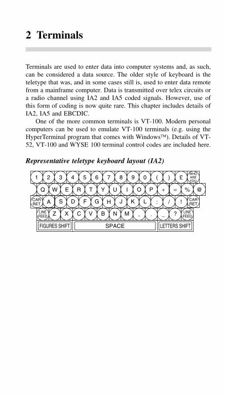
2 Terminals
Terminals are used to enter data into computer systems and, as such,can be considered a data source. The older style of keyboard is theteletype that was, and in some cases still is, used to enter data remotefrom a mainframe computer. Data is transmitted over telex circuits ora radio channel using IA2 and IA5 coded signals. However, use ofthis form of coding is now quite rare. This chapter includes details ofIA2, IA5 and EBCDIC.
One of the more common terminals is VT-100. Modern personalcomputers can be used to emulate VT-100 terminals (e.g. using theHyperTerminal program that comes with Windows). Details of VT-52, VT-100 and WYSE 100 terminal control codes are included here.
Representative teletype keyboard layout (IA2)
1
Q
A
Z X C V B N M _ ?, .
S D F G H J K L : / !
W E R T Y U I O P + = % @
2 3 4 5 6 7 8 9 0 ( ) £WHOAREYOU
CARRET
LINEFEED
LINEFEED
CARRET
FIGURES SHIFT LETTERS SHIFTSPACE
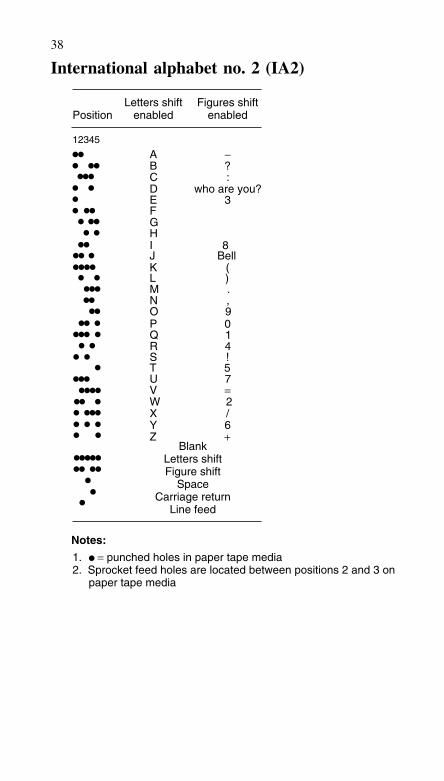
38
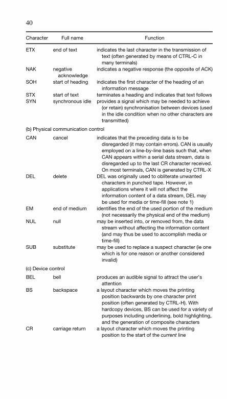
International alphabet no. 2 (IA2)
12345
Position
A
Letters shiftenabled
BCDEFGHIJKLMNOPQRSTUVWXYZ
−
Figures shiftenabled
?:
who are you?3
8Bell
().,9014!57=2/6+
BlankLetters shiftFigure shift
SpaceCarriage return
Line feed
Notes:
1. = punched holes in paper tape media2. Sprocket feed holes are located between positions 2 and 3 on paper tape media
39
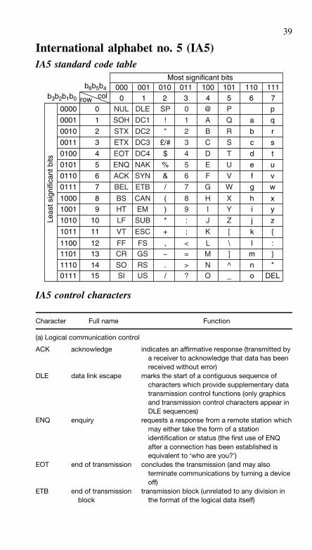
International alphabet no. 5 (IA5)IA5 standard code table
Leas
t sig
nific
ant b
its
row
b6b5b4
b3b2b1b0
000 001 011010 100 101 110Most significant bits
1110 1 32 4 5 6 7col
p
q
r
s
t
u
v
w
x
y
z
{
:}
"DEL
0000
0001
0010
0011
0100
0101
0110
0111
1000
1001
1010
1011
11001101
11100111
0
1
2
3
4
5
6
7
8
9
10
11
1213
1415
a
b
c
d
e
f
g
h
i
j
k
lm
no
NUL
SOH
STX
ETX
EOT
ENQ
ACK
BEL
BS
HT
LF
VT
FFCR
SOSI
DLE
DC1
DC2
DC3
DC4
NAK
SYN
ETB
CAN
EM
SUB
ESC
FSGS
RSUS
SP
!
"
£/#
$
%
&
/
(
)
+
,−./
*
0
1
3
2
4
5
6
7
8
9
:
;
<=
>?
@
A
B
C
D
E
F
G
H
I
J
K
LM
NO
P
Q
R
S
T
U
V
W
Y
X
Z
[
\]
^_
IA5 control characters
Character Full name Function
(a) Logical communication control
ACK acknowledge indicates an affirmative response (transmitted bya receiver to acknowledge that data has beenreceived without error)
DLE data link escape marks the start of a contiguous sequence ofcharacters which provide supplementary datatransmission control functions (only graphicsand transmission control characters appear inDLE sequences)
ENQ enquiry requests a response from a remote station whichmay either take the form of a stationidentification or status (the first use of ENQafter a connection has been established isequivalent to ‘who are you?’)
EOT end of transmission concludes the transmission (and may alsoterminate communications by turning a deviceoff)
ETB end of transmissionblock
transmission block (unrelated to any division inthe format of the logical data itself)
40
Character Full name Function
ETX end of text indicates the last character in the transmission oftext (often generated by means of CTRL-C inmany terminals)
NAK negativeacknowledge
indicates a negative response (the opposite of ACK)
SOH start of heading indicates the first character of the heading of aninformation message
STX start of text terminates a heading and indicates that text followsSYN synchronous idle provides a signal which may be needed to achieve
(or retain) synchronisation between devices (usedin the idle condition when no other characters aretransmitted)
(b) Physical communication control
CAN cancel indicates that the preceding data is to bedisregarded (it may contain errors). CAN is usuallyemployed on a line-by-line basis such that, whenCAN appears within a serial data stream, data isdisregarded up to the last CR character received.On most terminals, CAN is generated by CTRL-X
DEL delete DEL was originally used to obliterate unwantedcharacters in punched tape. However, inapplications where it will not affect theinformation content of a data stream, DEL maybe used for media or time-fill (see note 1)
EM end of medium identifies the end of the used portion of the medium(not necessarily the physical end of the medium)
NUL null may be inserted into, or removed from, the datastream without affecting the information content(and may thus be used to accomplish media ortime-fill)
SUB substitute may be used to replace a suspect character (ie onewhich is for one reason or another consideredinvalid)
(c) Device control
BEL bell produces an audible signal to attract the user’sattention
BS backspace a layout character which moves the printingposition backwards by one character printposition (often generated by CTRL-H). Withhardcopy devices, BS can be used for a variety ofpurposes including underlining, bold highlighting,and the generation of composite characters
CR carriage return a layout character which moves the printingposition to the start of the current line
41
Character Full name Function
DC1–DC4 device control used to enable or disable additional facilities whichmay be available at the receiver (often used tocontrol specialised printing functions)
FF form feed a layout character which moves the printing positionto the first printing line on the next page (form)
HT horizontaltabulation
a layout character which moves the printing positionto the next in a series of predefined horizontalprinting positions (horizontal tab settings)
LF line feed a layout character which moves the printingposition to the next printing line. In someequipment, LF is sometimes combined with CRso that the print position is moved to the start ofthe next line. To avoid confusion, LF issometimes referred to as NL (or new line)
VT verticaltabulation
a layout character which moves the printingposition to the next in a series of predefinedvertical printing positions (vertical tab. settings).Depending upon the current vertical tab. setting,VT is equivalent to one, or more, LF characters.
(d) Formatting and string processing (see note 2)
FS field separator terminates a file information blockGS group separator terminates a group information blockRS record separator terminates a record information blockUS unit separator terminates a unit information block
(e) Character/graphic set control
ESC escape used to modify or extend the standard characterset. The escape character changes the meaningof the character which follows according to somepreviously defined scheme. NUL, DELcommunication control characters must not beused in defining escape sequences
SI shift-in characters which follow SI should be interpretedaccording to the standard code table
SO shift-out characters which follow SO should be interpretedas being outside the standard code table. Themeaning of the control characters from columns0 and 1 are, however, preserved.
Notes:
1. Note that DEL, unlike other control characters which occupy columns 0 and 1, isin column 7 (all bits of the code for DEL are set to logic 1)
2. Information block separators have the following hierarchy (arranged in ascendingorder): US, RS, GS, FS. Also note that information blocks may not themselves bedivided by separators of higher order
42
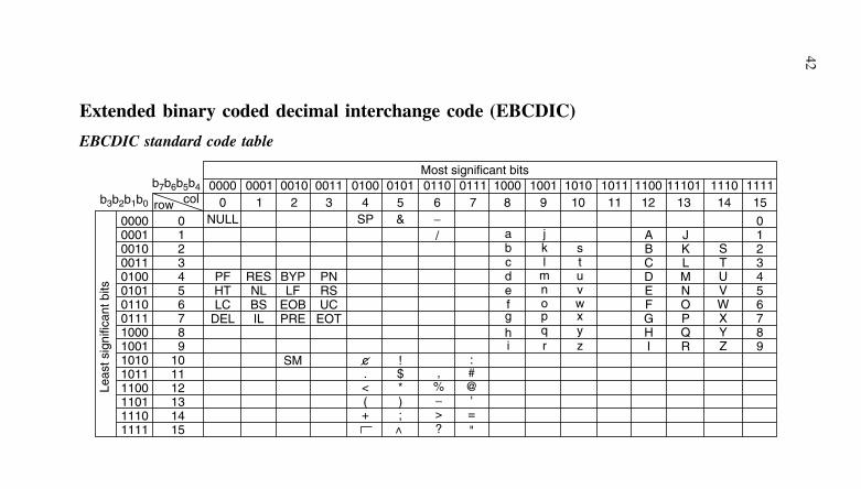
Extended binary coded decimal interchange code (EBCDIC)
EBCDIC standard code table
0000000100100011010001010110011110001001101010111100110111101111
0123456789
101112131415
Leas
t sig
nific
ant b
its
0123456789
JKLMNOPQR
ABCDEFGHI
STUVWXYZ
row
b7b6b5b4b3b2b1b0
0000 0001 00110010 0100 0101 0110Most significant bits
0111 1000 1001 1010 1011 1100 111010 1 32 4 5 6
NULL
PFHTLC
DEL
RESNLBSIL
BYPLF
EOBPRE
PNRSUC
EOT
SM
SP & −
c ! :. $ #,< * @%( ) '−+ ; =>
> "?
/
7 8 9 10 11 12 131110
141111
15col
abcdefghi
jkl
mnopqr
stuvwxyz
43
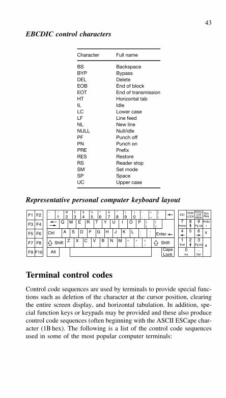
EBCDIC control characters
Character Full name
BS BackspaceBYP BypassDEL DeleteEOB End of blockEOT End of transmissionHT Horizontal tabIL IdleLC Lower caseLF Line feedNL New lineNULL Null/idlePF Punch offPN Punch onPRE PrefixRES RestoreRS Reader stopSM Set modeSP SpaceUC Upper case
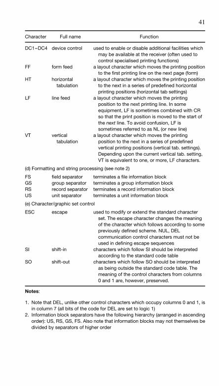
Representative personal computer keyboard layout
F1 F2~
`
! @ £ $ % ^ & * ( )
-1 2Q
A
Z X C V B N M
S D F G H J K L Enter
Shift
W E R T Y U I O P {
3 4 5 6 7 8 9 0−
=
+
\
|
}
][
: "';
< > ?
x
Home Pg Up
End Pg Dn x
F3 F4
F5 F6
F7 F8
F9 F10 Alt
Ctrl
CapsLock
ESC
7 8 9
4
1
Ins
0 .
2 3
5 6
NUMLOCK
SCROLLLOCK
BREAK
SysReq
PrtSc+
Del
Shift , . /
Terminal control codes
Control code sequences are used by terminals to provide special func-tions such as deletion of the character at the cursor position, clearingthe entire screen display, and horizontal tabulation. In addition, spe-cial function keys or keypads may be provided and these also producecontrol code sequences (often beginning with the ASCII ESCape char-acter (1B hex). The following is a list of the control code sequencesused in some of the most popular computer terminals:
44
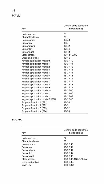
VT-52
KeyControl code sequence
(hexadecimal)
Horizontal tab 09Character delete 7FHome cursor 1B,48Cursor up 1B,41Cursor down 1B,42Cursor left 1B,44Cursor right 1B,43Clear screen 1B,48,1B,4AErase end of line 1B,4BKeypad application mode 0 1B,3F,70Keypad application mode 1 1B,3F,71Keypad application mode 2 1B,3F,72Keypad application mode 3 1B,3F,73Keypad application mode 4 1B,3F,74Keypad application mode 5 1B,3F,75Keypad application mode 6 1B,3F,76Keypad application mode 7 1B,3F,77Keypad application mode 8 1B,3F,78Keypad application mode 9 1B,3F,79Keypad application mode − 1B,3F,6DKeypad application mode , 1B,3F,6CKeypad application mode . 1B,3F,6EKeypad application mode ENTER 1B,3F,4DProgram function 1 (PF1) 1B,50Program function 2 (PF2) 1B,51Program function 3 (PF3) 1B,52Program function 4 (PF4) 1B,53
VT-100
KeyControl code sequence
(hexadecimal)
Horizontal tab 09Character delete 7FHome cursor 1B,5B,48Cursor up 1B,5B,41Cursor down 1B,5B,42Cursor left 1B,5B,44Cursor right 1B,5B,43Clear screen 1B,5B,48,1B,5B,32,4AErase end of line 1B,5B,4BInsert line 1B,5B,4C
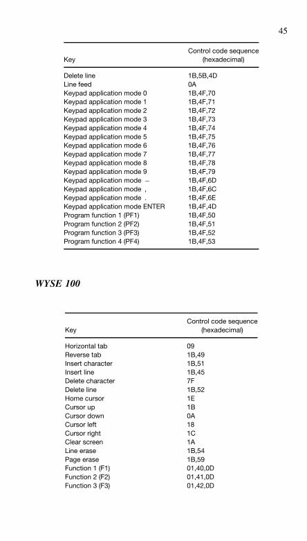
45
KeyControl code sequence
(hexadecimal)
Delete line 1B,5B,4DLine feed 0AKeypad application mode 0 1B,4F,70Keypad application mode 1 1B,4F,71Keypad application mode 2 1B,4F,72Keypad application mode 3 1B,4F,73Keypad application mode 4 1B,4F,74Keypad application mode 5 1B,4F,75Keypad application mode 6 1B,4F,76Keypad application mode 7 1B,4F,77Keypad application mode 8 1B,4F,78Keypad application mode 9 1B,4F,79Keypad application mode − 1B,4F,6DKeypad application mode , 1B,4F,6CKeypad application mode . 1B,4F,6EKeypad application mode ENTER 1B,4F,4DProgram function 1 (PF1) 1B,4F,50Program function 2 (PF2) 1B,4F,51Program function 3 (PF3) 1B,4F,52Program function 4 (PF4) 1B,4F,53
WYSE 100
KeyControl code sequence
(hexadecimal)
Horizontal tab 09Reverse tab 1B,49Insert character 1B,51Insert line 1B,45Delete character 7FDelete line 1B,52Home cursor 1ECursor up 1BCursor down 0ACursor left 18Cursor right 1CClear screen 1ALine erase 1B,54Page erase 1B,59Function 1 (F1) 01,40,0DFunction 2 (F2) 01,41,0DFunction 3 (F3) 01,42,0D
46
KeyControl code sequence
(hexadecimal)
Function 4 (F4) 01,43,0DFunction 5 (F5) 01,44,0DFunction 6 (F6) 01,45,0DFunction 7 (F7) 01,46,0DFunction 8 (F8) 01,47,0DShift function 1 (F1) 01,48,0DShift function 2 (F2) 01,49,0DShift function 3 (F3) 01,4A,0DShift function 4 (F4) 01,4B,0DShift function 5 (F5) 01,4C,0DShift function 6 (F6) 01,4D,0DShift function 7 (F7) 01,4E,0DShift function 8 (F8) 01,4F,0D
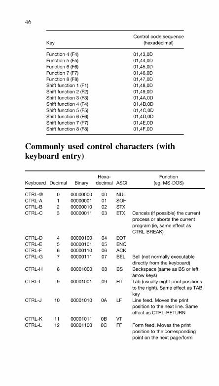
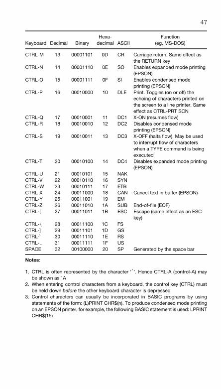
Commonly used control characters (withkeyboard entry)
Keyboard Decimal BinaryHexa-
decimal ASCIIFunction
(eg, MS-DOS)
CTRL-@ 0 00000000 00 NULCTRL-A 1 00000001 01 SOHCTRL-B 2 00000010 02 STXCTRL-C 3 00000011 03 ETX Cancels (if possible) the current
process or aborts the currentprogram (ie, same effect asCTRL-BREAK)
CTRL-D 4 00000100 04 EOTCTRL-E 5 00000101 05 ENQCTRL-F 6 00000110 06 ACKCTRL-G 7 00000111 07 BEL Bell (not normally executable
directly from the keyboard)CTRL-H 8 00001000 08 BS Backspace (same as BS or left
arrow keys)CTRL-I 9 00001001 09 HT Tab (usually eight print positions
to the right). Same effect as TABkey
CTRL-J 10 00001010 0A LF Line feed. Moves the printposition to the next line. Sameeffect as CTRL-RETURN
CTRL-K 11 00001011 0B VTCTRL-L 12 00001100 0C FF Form feed. Moves the print
position to the correspondingpoint on the next page/form
47
Keyboard Decimal BinaryHexa-
decimal ASCIIFunction
(eg, MS-DOS)
CTRL-M 13 00001101 0D CR Carriage return. Same effect asthe RETURN key
CTRL-N 14 00001110 0E SO Enables expanded mode printing(EPSON)
CTRL-O 15 00001111 0F SI Enables condensed modeprinting (EPSON)
CTRL-P 16 00010000 10 DLE Print. Toggles (on or off) theechoing of characters printed onthe screen to a line printer. Sameeffect as CTRL-PRT SCN
CTRL-Q 17 00010001 11 DC1 X-ON (resumes flow)CTRL-R 18 00010010 12 DC2 Disables condensed mode
printing (EPSON)CTRL-S 19 00010011 13 DC3 X-OFF (halts flow). May be used
to interrupt flow of characterswhen a TYPE command is beingexecuted
CTRL-T 20 00010100 14 DC4 Disables expanded mode printing(EPSON)
CTRL-U 21 00010101 15 NAKCTRL-V 22 00010110 16 SYNCTRL-W 23 00010111 17 ETBCTRL-X 24 00011000 18 CAN Cancel text in buffer (EPSON)CTRL-Y 25 00011001 19 EMCTRL-Z 26 00011010 1A SUB End-of-file (EOF)CTRL-[ 27 00011011 1B ESC Escape (same effect as an ESC
key)CTRL-\ 28 00011100 1C FSCTRL-] 29 00011101 1D GSCTRL- 30 00011110 1E RSCTRL-− 31 00011111 1F USSPACE 32 00100000 20 SP Generated by the space bar
Notes:
1. CTRL is often represented by the character ‘ˆ ’. Hence CTRL-A (control-A) maybe shown as ˆA
2. When entering control characters from a keyboard, the control key (CTRL) mustbe held down before the other keyboard character is depressed
3. Control characters can usually be incorporated in BASIC programs by usingstatements of the form: (L)PRINT CHR$(n). To produce condensed mode printingon an EPSON printer, for example, the following BASIC statement is used: LPRINTCHR$(15)
3 Transmission media
Data communications is about moving or copying data from one placeto another. This may be from a personal computer to a file server ona local area network (LAN), or may be from the Internet to a personalcomputer. In all cases data must be carried over a cable at some point;this could be a copper cable or an optical fibre cable.
This chapter describes the types of cable and their performance. Itis important to know the limitations of the transmission media, in orderto understand why modems, repeaters and other data communicationsequipment (DCE) is necessary.
Transmission element specifications
The transmission path in a data communications system may comprisecables, amplifiers/regenerators, attenuators, filters, diplexers, etc. Theelectrical characteristics of such items are usually specified in termsof one or more of the following parameters.
Gain or loss
The gain or loss of an element within a transmission path is the ratioof output voltage to input voltage (ie, voltage gain), output current toinput current (ie, current gain), or output power to input power (ie,power gain). Gain is often expressed in decibels (dB) where:
voltage gain in dB = 20 log10
(Vout
Vin
)
current gain in dB = 20 log10
(Iout
Iin
)
power gain in dB = 10 log10
(Pout
Pin
)
Note that in the two former cases, the specification is only meaningfulwhere the input and output impedances of the element are identical.
49
Input impedance
The input impedance of an element within a transmission path is theratio of input voltage to input current and it is expressed in ohms.The input of an amplifier is normally purely resistive (ie, the reac-tive component is negligible) in the middle of its working frequencyrange (ie, the mid-band) and hence, in such cases, input impedance issynonymous with input resistance.
Output impedance
The output impedance of an element within a transmission path isthe ratio of open-circuit output voltage to short-circuit output currentand is measured in ohms. Note that this impedance is internal to theelement and should not be confused with the impedance of the loador circuit to which the element is connected. (Usually, but not always,these will have identical values in order to maximise power transfer).
Frequency response
The frequency response of a transmission element is usually specifiedin terms of the upper and lower cut-off frequencies of the element.These frequencies are those at which the output power has droppedto 50% (otherwise known as the −3dB points) or where the voltagegain has dropped to 70.7% of its mid-band value.
Bandwidth
The bandwidth of a transmission element is usually taken as the dif-ference between the two cut-off frequencies. It is equivalent to thefrequency span for which the gain is maintained within defined limits(usually within 3dB of the mid-band power gain).
Phase shift
The phase shift of a transmission element is defined as the phaseangle (in electrical degrees or radians) of the output signal whencompared with the input signal (taken as the reference). Phase shiftis substantially constant within the mid-band region but is liable to amarked variation beyond cut-off due to the increasing significance ofreactance.
50
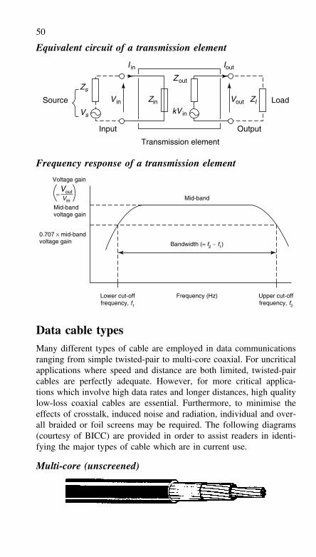
Equivalent circuit of a transmission element
Zs
ZIVin Vout
Zout
kVin
Zin
I in Iout
Vs
Source Load
Input Output
Transmission element
Frequency response of a transmission element
Mid-band
Voltage gain
Mid-bandvoltage gain
0.707 × mid-bandvoltage gain
= VoutVin
Bandwidth (= f2 − f1)
Frequency (Hz)Lower cut-offfrequency, f1
Upper cut-offfrequency, f2
Data cable typesMany different types of cable are employed in data communicationsranging from simple twisted-pair to multi-core coaxial. For uncriticalapplications where speed and distance are both limited, twisted-paircables are perfectly adequate. However, for more critical applica-tions which involve high data rates and longer distances, high qualitylow-loss coaxial cables are essential. Furthermore, to minimise theeffects of crosstalk, induced noise and radiation, individual and over-all braided or foil screens may be required. The following diagrams(courtesy of BICC) are provided in order to assist readers in identi-fying the major types of cable which are in current use.
Multi-core (unscreened)
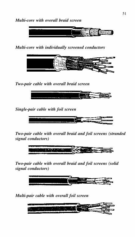
51
Multi-core with overall braid screen
Multi-core with individually screened conductors
Two-pair cable with overall braid screen
Single-pair cable with foil screen
Two-pair cable with overall braid and foil screens (strandedsignal conductors)
Two-pair cable with overall braid and foil screens (solidsignal conductors)
Multi-pair cable with overall foil screen
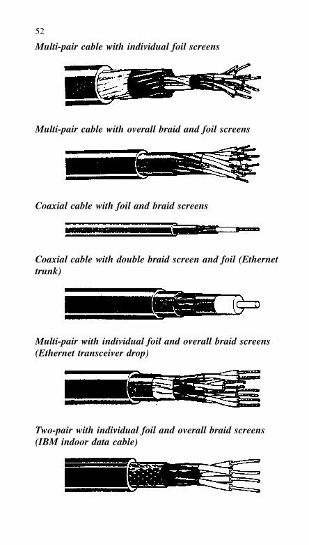
52
Multi-pair cable with individual foil screens
Multi-pair cable with overall braid and foil screens
Coaxial cable with foil and braid screens
Coaxial cable with double braid screen and foil (Ethernettrunk)
Multi-pair with individual foil and overall braid screens(Ethernet transceiver drop)
Two-pair with individual foil and overall braid screens(IBM indoor data cable)
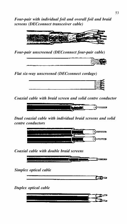
53
Four-pair with individual foil and overall foil and braidscreens (DECconnect transceiver cable)
Four-pair unscreened (DECconnect four-pair cable)
Flat six-way unscreened (DECconnect cordage)
Coaxial cable with braid screen and solid centre conductor
Dual coaxial cable with individual braid screens and solidcentre conductors
Coaxial cable with double braid screens
Simplex optical cable
Duplex optical cable
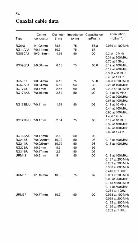
54
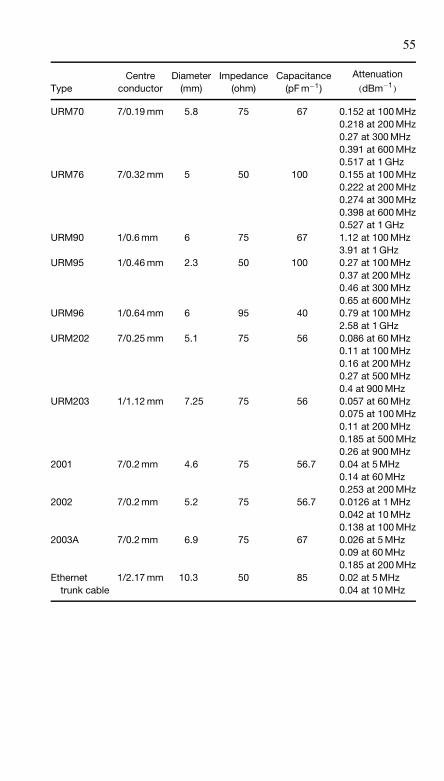
Coaxial cable data
TypeCentre
conductorDiameter
(mm)Impedance
(ohm)Capacitance
(pF m−1)
Attenuation
(dBm−1)
RG6/U 1/1.02 mm 68.6 75 56.8 0.069 at 100 MHzRG11A/U 7/0.41 mm 10.3 75 67RG58C/U 19/0.18 mm 4.95 50 100 0.2 at 10 MHz
0.31 at 200 MHz0.76 at 1 GHz
RG59B/U 1/0.58 mm 6.15 75 60.6 0.12 at 100 MHz0.19 at 200 MHz0.3 at 400 MHz0.46 at 1 GHz
RG59/U 1/0.64 mm 6.15 75 56.8 0.098 at 100 MHzRG62A/U 1/0.64 mm 6.15 93 36 0.26 at 400 MHzRG174/U 1/0.4 mm 2.56 60 101 0.292 at 100 MHzRG174A/U 7/0.16 mm 2.54 50 100 0.11 at 10 MHz
0.42 at 200 MHz0.67 at 400 MHz
RG178B/U 7/0.1 mm 1.91 50 106 0.18 at 10 MHz0.44 at 100 MHz0.95 at 400 MHz1.4 at 1 GHz
RG179B/U 7/0.1 mm 2.54 75 66 0.19 at 10 MHz0.32 at 100 MHz0.69 at 400 MHz0.82 at 1 GHz
RG188A/U 7/0.17 mm 2.6 50 93RG213/U 7/0.029 mm 10.29 50 98 0.18 at 400 MHzRG214/U 7/0.029 mm 10.79 50 98 0.18 at 400 MHzRG223/U 1/0.9 mm 5.5 50 96RG316/U 7/0.17 mm 2.6 50 102URM43 1/0.9 mm 5 50 100 0.13 at 100 MHz
0.187 at 200 MHz0.232 at 300 MHz0.338 at 600 MHz0.446 at 1 GHz
URM57 1/1.15 mm 10.3 75 67 0.061 at 100 MHz0.09 at 200 MHz0.113 at 300 MHz0.17 at 600 MHz0.231 at 1 GHz
URM67 7/0.77 mm 10.3 50 100 0.068 at 100 MHz0.099 at 200 MHz0.125 at 300 MHz0.186 at 500 MHz0.252 at 1 GHz
55
TypeCentre
conductorDiameter
(mm)Impedance
(ohm)Capacitance
(pF m−1)
Attenuation
(dBm−1)
URM70 7/0.19 mm 5.8 75 67 0.152 at 100 MHz0.218 at 200 MHz0.27 at 300 MHz0.391 at 600 MHz0.517 at 1 GHz
URM76 7/0.32 mm 5 50 100 0.155 at 100 MHz0.222 at 200 MHz0.274 at 300 MHz0.398 at 600 MHz0.527 at 1 GHz
URM90 1/0.6 mm 6 75 67 1.12 at 100 MHz3.91 at 1 GHz
URM95 1/0.46 mm 2.3 50 100 0.27 at 100 MHz0.37 at 200 MHz0.46 at 300 MHz0.65 at 600 MHz
URM96 1/0.64 mm 6 95 40 0.79 at 100 MHz2.58 at 1 GHz
URM202 7/0.25 mm 5.1 75 56 0.086 at 60 MHz0.11 at 100 MHz0.16 at 200 MHz0.27 at 500 MHz0.4 at 900 MHz
URM203 1/1.12 mm 7.25 75 56 0.057 at 60 MHz0.075 at 100 MHz0.11 at 200 MHz0.185 at 500 MHz0.26 at 900 MHz
2001 7/0.2 mm 4.6 75 56.7 0.04 at 5 MHz0.14 at 60 MHz0.253 at 200 MHz
2002 7/0.2 mm 5.2 75 56.7 0.0126 at 1 MHz0.042 at 10 MHz0.138 at 100 MHz
2003A 7/0.2 mm 6.9 75 67 0.026 at 5 MHz0.09 at 60 MHz0.185 at 200 MHz
Ethernet 1/2.17 mm 10.3 50 85 0.02 at 5 MHztrunk cable 0.04 at 10 MHz
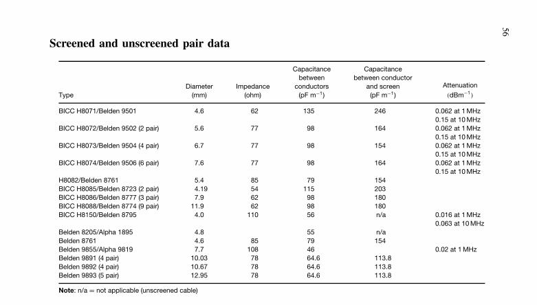
56Screened and unscreened pair data
TypeDiameter
(mm)Impedance
(ohm)
Capacitancebetween
conductors(pF m−1)
Capacitancebetween conductor
and screen(pF m−1)
Attenuation
(dBm−1)
BICC H8071/Belden 9501 4.6 62 135 246 0.062 at 1 MHz0.15 at 10 MHz
BICC H8072/Belden 9502 (2 pair) 5.6 77 98 164 0.062 at 1 MHz0.15 at 10 MHz
BICC H8073/Belden 9504 (4 pair) 6.7 77 98 154 0.062 at 1 MHz0.15 at 10 MHz
BICC H8074/Belden 9506 (6 pair) 7.6 77 98 164 0.062 at 1 MHz0.15 at 10 MHz
H8082/Belden 8761 5.4 85 79 154BICC H8085/Belden 8723 (2 pair) 4.19 54 115 203BICC H8086/Belden 8777 (3 pair) 7.9 62 98 180BICC H8088/Belden 8774 (9 pair) 11.9 62 98 180BICC H8150/Belden 8795 4.0 110 56 n/a 0.016 at 1 MHz
0.063 at 10 MHzBelden 8205/Alpha 1895 4.8 55 n/aBelden 8761 4.6 85 79 154Belden 9855/Alpha 9819 7.7 108 46 0.02 at 1 MHzBelden 9891 (4 pair) 10.03 78 64.6 113.8Belden 9892 (4 pair) 10.67 78 64.6 113.8Belden 9893 (5 pair) 12.95 78 64.6 113.8
Note: n/a = not applicable (unscreened cable)
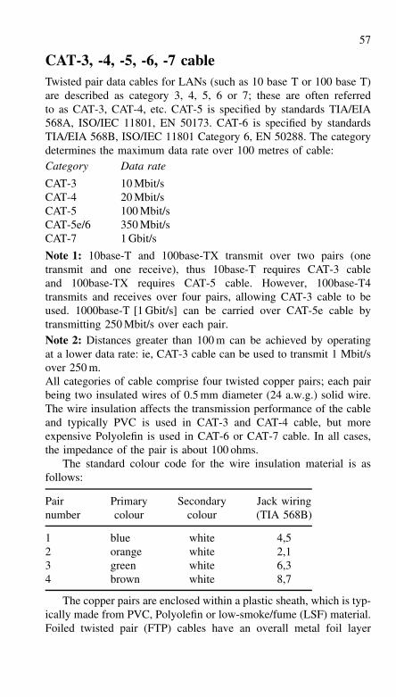
57
CAT-3, -4, -5, -6, -7 cableTwisted pair data cables for LANs (such as 10 base T or 100 base T)are described as category 3, 4, 5, 6 or 7; these are often referredto as CAT-3, CAT-4, etc. CAT-5 is specified by standards TIA/EIA568A, ISO/IEC 11801, EN 50173. CAT-6 is specified by standardsTIA/EIA 568B, ISO/IEC 11801 Category 6, EN 50288. The categorydetermines the maximum data rate over 100 metres of cable:Category Data rate
CAT-3 10 Mbit/sCAT-4 20 Mbit/sCAT-5 100 Mbit/sCAT-5e/6 350 Mbit/sCAT-7 1 Gbit/s
Note 1: 10base-T and 100base-TX transmit over two pairs (onetransmit and one receive), thus 10base-T requires CAT-3 cableand 100base-TX requires CAT-5 cable. However, 100base-T4transmits and receives over four pairs, allowing CAT-3 cable to beused. 1000base-T [1 Gbit/s] can be carried over CAT-5e cable bytransmitting 250 Mbit/s over each pair.Note 2: Distances greater than 100 m can be achieved by operatingat a lower data rate: ie, CAT-3 cable can be used to transmit 1 Mbit/sover 250 m.All categories of cable comprise four twisted copper pairs; each pairbeing two insulated wires of 0.5 mm diameter (24 a.w.g.) solid wire.The wire insulation affects the transmission performance of the cableand typically PVC is used in CAT-3 and CAT-4 cable, but moreexpensive Polyolefin is used in CAT-6 or CAT-7 cable. In all cases,the impedance of the pair is about 100 ohms.
The standard colour code for the wire insulation material is asfollows:
Pair Primary Secondary Jack wiringnumber colour colour (TIA 568B)
1 blue white 4,52 orange white 2,13 green white 6,34 brown white 8,7
The copper pairs are enclosed within a plastic sheath, which is typ-ically made from PVC, Polyolefin or low-smoke/fume (LSF) material.Foiled twisted pair (FTP) cables have an overall metal foil layer
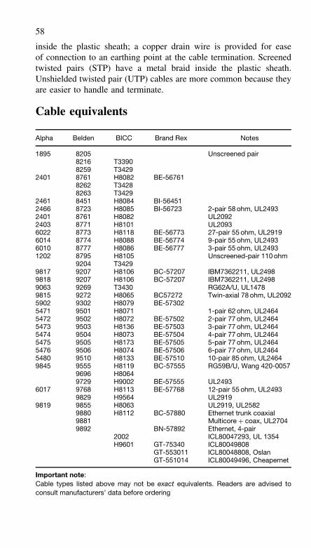
58
inside the plastic sheath; a copper drain wire is provided for easeof connection to an earthing point at the cable termination. Screenedtwisted pairs (STP) have a metal braid inside the plastic sheath.Unshielded twisted pair (UTP) cables are more common because theyare easier to handle and terminate.
Cable equivalents
Alpha Belden BICC Brand Rex Notes
1895 8205 Unscreened pair8216 T33908259 T3429
2401 8761 H8082 BE-567618262 T34288263 T3429
2461 8451 H8084 BI-564512466 8723 H8085 BI-56723 2-pair 58 ohm, UL24932401 8761 H8082 UL20922403 8771 H8101 UL20936022 8773 H8118 BE-56773 27-pair 55 ohm, UL29196014 8774 H8088 BE-56774 9-pair 55 ohm, UL24936010 8777 H8086 BE-56777 3-pair 55 ohm, UL24931202 8795 H8105 Unscreened-pair 110 ohm
9204 T34299817 9207 H8106 BC-57207 IBM7362211, UL24989818 9207 H8106 BC-57207 IBM7362211, UL24989063 9269 T3430 RG62A/U, UL14789815 9272 H8065 BC57272 Twin-axial 78 ohm, UL20925902 9302 H8079 BE-573025471 9501 H8071 1-pair 62 ohm, UL24645472 9502 H8072 BE-57502 2-pair 77 ohm, UL24645473 9503 H8136 BE-57503 3-pair 77 ohm, UL24645474 9504 H8073 BE-57504 4-pair 77 ohm, UL24645475 9505 H8173 BE-57505 5-pair 77 ohm, UL24645476 9506 H8074 BE-57506 6-pair 77 ohm, UL24645480 9510 H8133 BE-57510 10-pair 85 ohm, UL24649845 9555 H8119 BC-57555 RG59B/U, Wang 420-0057
9696 H80649729 H9002 BE-57555 UL2493
6017 9768 H8113 BE-57768 12-pair 55 ohm, UL24939829 H9564 UL2919
9819 9855 H8063 UL2919, UL25829880 H8112 BC-57880 Ethernet trunk coaxial9881 Multicore + coax, UL27049892 BN-57892 Ethernet, 4-pair
2002 ICL80047293, UL 1354H9601 GT-75340 ICL80049808
GT-553011 ICL80048808, OslanGT-551014 ICL80049496, Cheapernet
Important note:Cable types listed above may not be exact equivalents. Readers are advised toconsult manufacturers’ data before ordering
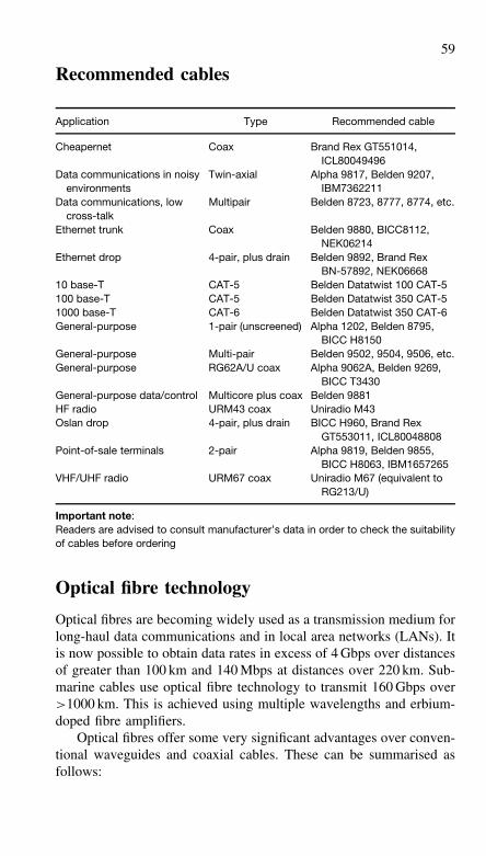
59
Recommended cables
Application Type Recommended cable
Cheapernet Coax Brand Rex GT551014,ICL80049496
Data communications in noisyenvironments
Twin-axial Alpha 9817, Belden 9207,IBM7362211
Data communications, lowcross-talk
Multipair Belden 8723, 8777, 8774, etc.
Ethernet trunk Coax Belden 9880, BICC8112,NEK06214
Ethernet drop 4-pair, plus drain Belden 9892, Brand RexBN-57892, NEK06668
10 base-T CAT-5 Belden Datatwist 100 CAT-5100 base-T CAT-5 Belden Datatwist 350 CAT-51000 base-T CAT-6 Belden Datatwist 350 CAT-6General-purpose 1-pair (unscreened) Alpha 1202, Belden 8795,
BICC H8150General-purpose Multi-pair Belden 9502, 9504, 9506, etc.General-purpose RG62A/U coax Alpha 9062A, Belden 9269,
BICC T3430General-purpose data/control Multicore plus coax Belden 9881HF radio URM43 coax Uniradio M43Oslan drop 4-pair, plus drain BICC H960, Brand Rex
GT553011, ICL80048808Point-of-sale terminals 2-pair Alpha 9819, Belden 9855,
BICC H8063, IBM1657265VHF/UHF radio URM67 coax Uniradio M67 (equivalent to
RG213/U)
Important note:Readers are advised to consult manufacturer’s data in order to check the suitabilityof cables before ordering
Optical fibre technology
Optical fibres are becoming widely used as a transmission medium forlong-haul data communications and in local area networks (LANs). Itis now possible to obtain data rates in excess of 4 Gbps over distancesof greater than 100 km and 140 Mbps at distances over 220 km. Sub-marine cables use optical fibre technology to transmit 160 Gbps over>1000 km. This is achieved using multiple wavelengths and erbium-doped fibre amplifiers.
Optical fibres offer some very significant advantages over conven-tional waveguides and coaxial cables. These can be summarised asfollows:
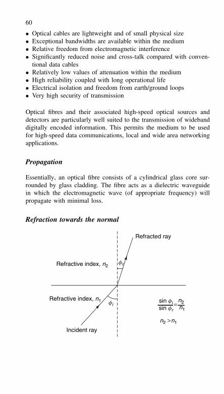
60
• Optical cables are lightweight and of small physical size• Exceptional bandwidths are available within the medium• Relative freedom from electromagnetic interference• Significantly reduced noise and cross-talk compared with conven-
tional data cables• Relatively low values of attenuation within the medium• High reliability coupled with long operational life• Electrical isolation and freedom from earth/ground loops• Very high security of transmission
Optical fibres and their associated high-speed optical sources anddetectors are particularly well suited to the transmission of widebanddigitally encoded information. This permits the medium to be usedfor high-speed data communications, local and wide area networkingapplications.
Propagation
Essentially, an optical fibre consists of a cylindrical glass core sur-rounded by glass cladding. The fibre acts as a dielectric waveguidein which the electromagnetic wave (of appropriate frequency) willpropagate with minimal loss.
Refraction towards the normal
Refractive index, n1
Refractive index, n2
Refracted ray
Incident ray
sin fisin fr
=n2n1
n1n2 >
fi
fr
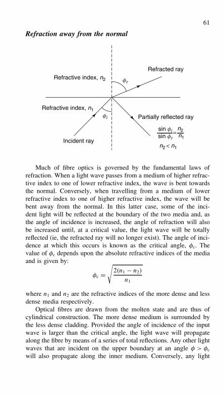
61
Refraction away from the normal
Refractive index, n1
Refractive index, n2
Refracted ray
Partially reflected ray
sin fisin fr
=n2n1
n2 < n1Incident ray
fr
fi
Much of fibre optics is governed by the fundamental laws ofrefraction. When a light wave passes from a medium of higher refrac-tive index to one of lower refractive index, the wave is bent towardsthe normal. Conversely, when travelling from a medium of lowerrefractive index to one of higher refractive index, the wave will bebent away from the normal. In this latter case, some of the inci-dent light will be reflected at the boundary of the two media and, asthe angle of incidence is increased, the angle of refraction will alsobe increased until, at a critical value, the light wave will be totallyreflected (ie, the refracted ray will no longer exist). The angle of inci-dence at which this occurs is known as the critical angle, φc. Thevalue of φc depends upon the absolute refractive indices of the mediaand is given by:
φc =√
2(n1 − n2)
n1
where n1 and n2 are the refractive indices of the more dense and lessdense media respectively.
Optical fibres are drawn from the molten state and are thus ofcylindrical construction. The more dense medium is surrounded bythe less dense cladding. Provided the angle of incidence of the inputwave is larger than the critical angle, the light wave will propagatealong the fibre by means of a series of total reflections. Any other lightwaves that are incident on the upper boundary at an angle φ > φc
will also propagate along the inner medium. Conversely, any light
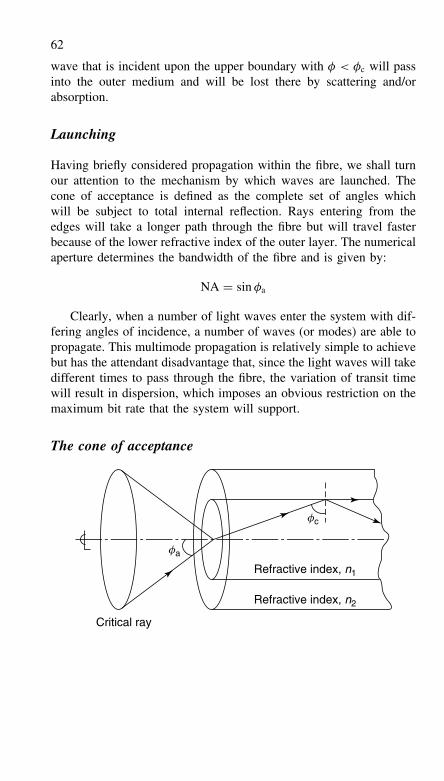
62
wave that is incident upon the upper boundary with φ < φc will passinto the outer medium and will be lost there by scattering and/orabsorption.
Launching
Having briefly considered propagation within the fibre, we shall turnour attention to the mechanism by which waves are launched. Thecone of acceptance is defined as the complete set of angles whichwill be subject to total internal reflection. Rays entering from theedges will take a longer path through the fibre but will travel fasterbecause of the lower refractive index of the outer layer. The numericalaperture determines the bandwidth of the fibre and is given by:
NA = sin φa
Clearly, when a number of light waves enter the system with dif-fering angles of incidence, a number of waves (or modes) are able topropagate. This multimode propagation is relatively simple to achievebut has the attendant disadvantage that, since the light waves will takedifferent times to pass through the fibre, the variation of transit timewill result in dispersion, which imposes an obvious restriction on themaximum bit rate that the system will support.
The cone of acceptance
Refractive index, n1
Critical ray
fc
fa
Refractive index, n2
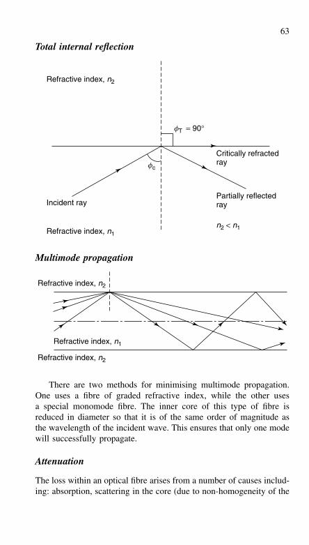
63
Total internal reflection
Critically refractedray
Partially reflectedrayIncident ray
n2 < n1Refractive index, n1
Refractive index, n2
fc
fT = 90°
Multimode propagation
Refractive index, n2
Refractive index, n2
Refractive index, n1
There are two methods for minimising multimode propagation.One uses a fibre of graded refractive index, while the other usesa special monomode fibre. The inner core of this type of fibre isreduced in diameter so that it is of the same order of magnitude asthe wavelength of the incident wave. This ensures that only one modewill successfully propagate.
Attenuation
The loss within an optical fibre arises from a number of causes includ-ing: absorption, scattering in the core (due to non-homogeneity of the
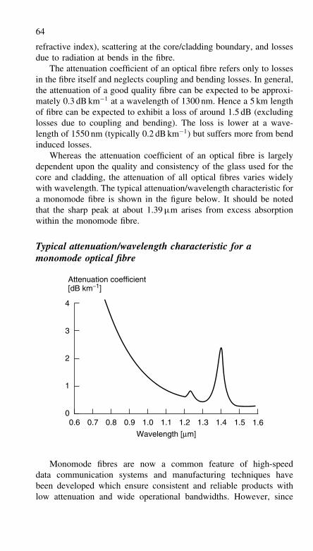
64
refractive index), scattering at the core/cladding boundary, and lossesdue to radiation at bends in the fibre.
The attenuation coefficient of an optical fibre refers only to lossesin the fibre itself and neglects coupling and bending losses. In general,the attenuation of a good quality fibre can be expected to be approxi-mately 0.3 dB km−1 at a wavelength of 1300 nm. Hence a 5 km lengthof fibre can be expected to exhibit a loss of around 1.5 dB (excludinglosses due to coupling and bending). The loss is lower at a wave-length of 1550 nm (typically 0.2 dB km−1) but suffers more from bendinduced losses.
Whereas the attenuation coefficient of an optical fibre is largelydependent upon the quality and consistency of the glass used for thecore and cladding, the attenuation of all optical fibres varies widelywith wavelength. The typical attenuation/wavelength characteristic fora monomode fibre is shown in the figure below. It should be notedthat the sharp peak at about 1.39 µm arises from excess absorptionwithin the monomode fibre.
Typical attenuation/wavelength characteristic for amonomode optical fibre
Wavelength [µm]
Attenuation coefficient[dB km−1]
0
3
2
1
4
0.6 0.7 0.8 0.9 1.0 1.1 1.2 1.3 1.4 1.5 1.6
Monomode fibres are now a common feature of high-speeddata communication systems and manufacturing techniques havebeen developed which ensure consistent and reliable products withlow attenuation and wide operational bandwidths. However, since
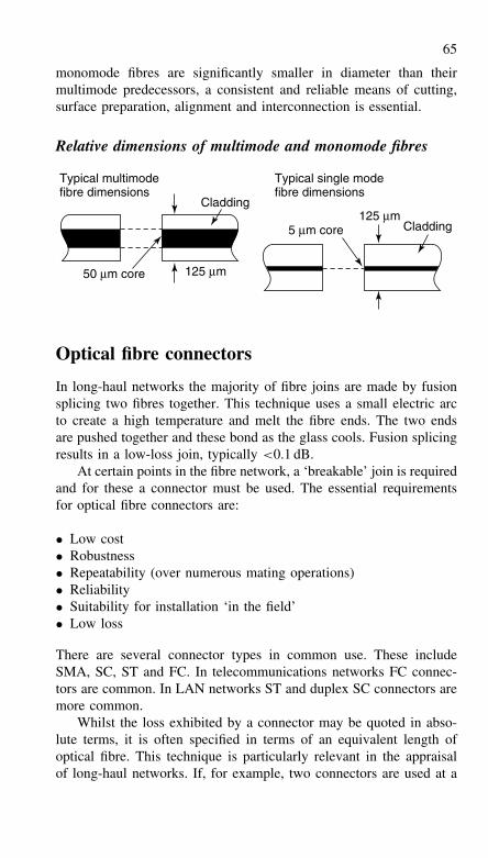
65
monomode fibres are significantly smaller in diameter than theirmultimode predecessors, a consistent and reliable means of cutting,surface preparation, alignment and interconnection is essential.
Relative dimensions of multimode and monomode fibres
Cladding
Cladding125 µm
5 µm core
50 µm core
Typical multimodefibre dimensions
Typical single modefibre dimensions
125 µm
Optical fibre connectors
In long-haul networks the majority of fibre joins are made by fusionsplicing two fibres together. This technique uses a small electric arcto create a high temperature and melt the fibre ends. The two endsare pushed together and these bond as the glass cools. Fusion splicingresults in a low-loss join, typically <0.1 dB.
At certain points in the fibre network, a ‘breakable’ join is requiredand for these a connector must be used. The essential requirementsfor optical fibre connectors are:
• Low cost• Robustness• Repeatability (over numerous mating operations)• Reliability• Suitability for installation ‘in the field’• Low loss
There are several connector types in common use. These includeSMA, SC, ST and FC. In telecommunications networks FC connec-tors are common. In LAN networks ST and duplex SC connectors aremore common.
Whilst the loss exhibited by a connector may be quoted in abso-lute terms, it is often specified in terms of an equivalent length ofoptical fibre. This technique is particularly relevant in the appraisalof long-haul networks. If, for example, two connectors are used at a
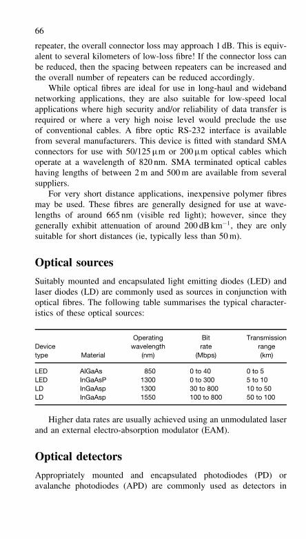
66
repeater, the overall connector loss may approach 1 dB. This is equiv-alent to several kilometers of low-loss fibre! If the connector loss canbe reduced, then the spacing between repeaters can be increased andthe overall number of repeaters can be reduced accordingly.
While optical fibres are ideal for use in long-haul and widebandnetworking applications, they are also suitable for low-speed localapplications where high security and/or reliability of data transfer isrequired or where a very high noise level would preclude the useof conventional cables. A fibre optic RS-232 interface is availablefrom several manufacturers. This device is fitted with standard SMAconnectors for use with 50/125 µm or 200 µm optical cables whichoperate at a wavelength of 820 nm. SMA terminated optical cableshaving lengths of between 2 m and 500 m are available from severalsuppliers.
For very short distance applications, inexpensive polymer fibresmay be used. These fibres are generally designed for use at wave-lengths of around 665 nm (visible red light); however, since theygenerally exhibit attenuation of around 200 dB km−1, they are onlysuitable for short distances (ie, typically less than 50 m).
Optical sources
Suitably mounted and encapsulated light emitting diodes (LED) andlaser diodes (LD) are commonly used as sources in conjunction withoptical fibres. The following table summarises the typical character-istics of these optical sources:
Devicetype Material
Operatingwavelength
(nm)
Bitrate
(Mbps)
Transmissionrange(km)
LED AlGaAs 850 0 to 40 0 to 5LED InGaAsP 1300 0 to 300 5 to 10LD InGaAsp 1300 30 to 800 10 to 50LD InGaAsp 1550 100 to 800 50 to 100
Higher data rates are usually achieved using an unmodulated laserand an external electro-absorption modulator (EAM).
Optical detectors
Appropriately mounted and encapsulated photodiodes (PD) oravalanche photodiodes (APD) are commonly used as detectors in
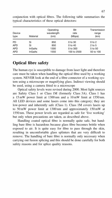
67
conjunction with optical fibres. The following table summarises thetypical characteristics of these optical detectors:
Devicetype Material
Operatingwavelength
(nm)
Bitrate
(Mbps)
Transmissionrange(km)
PD Si 850 0 to 30 0 to 2APD Si 850 0 to 40 2 to 5APD InGaAs 1300 0 to 300 5 to 50APD InGaAs 1550 100 to 2500 50 to 100
Optical fibre safety
The human eye is susceptible to damage from laser light and thereforecare must be taken when handling the optical fibre used by a workingsystem. NEVER look at the end of a fibre connector of a working sys-tem using a microscope or magnifying glass. Indirect viewing shouldbe used, using a camera fitted to a microscope
Optical safety levels were revised during 2000. Most light sourcesare Safety Class 1 or Class 1M (formerly Class 3A). Class 1 hasa 15 mW power limit at 1300 nm and a 10 mW limit at 1550 nm.All LED devices and some lasers come into this category; they arelow-power and inherently safe (Class 1). Class 1M covers lasers upto 50 mW power limit at 1300 nm and approximately 150 mW at1550 nm. These power levels are regarded as safe for ‘live working’but only when precautions are taken, as described above.
Handling coated optical fibre is normally quite safe, but hand-ling bare fibre is hazardous because glass fibre becomes brittle whenexposed to air. It is quite easy for fibre to pass through the skin,resulting in uncomfortable glass splinters that are very difficult toremove. The handling of bare fibre is normally only necessary whencarrying out fusion splicing and this should be done carefully for bothsafety reasons and for splice quality reasons.
4 Serial interfaces
Serial interfaces are used to connect signals from the personal com-puter to data communication equipment or other computers usingcopper cables.
The most common serial interface is RS-232, otherwise known asV.24. This has been used for many years and has been continuallyenhanced to make sure that it can still provide a valuable function.Most personal computers have at least one RS-232 port. The ITUissued the latest V.24 specification at the end of year 2000.
A number of interface specifications have been used where RS-232 has not been suitable. The most recent are the Universal SerialBus (USB) and IEEE-1394 (Firewire), which permit very high datarates over copper cables. These interfaces are described here.
Serial data transmission
In serial data transmission one data bit is transmitted after another.In order to transmit a byte of data it is therefore necessary to convertincoming parallel data from the bus into a serial bit stream which canbe transmitted along a line.
Serial data transmission can be synchronous (clocked) or asyn-chronous (non-clocked). The latter method has obvious advantagesand is by far the most popular method. The rate at which data is trans-mitted is given by the number of bits transmitted per unit time. Thecommonly adopted unit is the ‘baud’, with 1 baud roughly equivalentto 1 bit per second.
It should, however, be noted that there is a subtle differencebetween the bit rate as perceived by the computer and the baud ratepresented in the transmission medium. The reason is simply that someoverhead in terms of additional synchronising bits is required in orderto recover asynchronously transmitted data.
In the case of a typical RS-232C link, a total of 11 bits is requiredto transmit only seven bits of data. A line baud rate of 600 baud thusrepresents a useful data transfer rate of only some 382 bits per second.
Many modern serial data transmission systems can trace their ori-gins to the 20 mA current loop interface which was once commonlyused to connect a teletype unit to the minicomputer system. Thissystem was based on the following logic levels:
69
Mark = logic 1 = 20 mA current flowing
Space = logic 0 = no current flowing
where the terms ‘mark’ and ‘space’ simply refer to the presence orabsence of a current.
This system was extended to cater for more modern and morecomplex peripherals for which voltage, rather than current, levels wereappropriate.
Serial I/O devicesSince the data present on a microprocessor bus exists primarily inparallel form (it is byte wide) serial I/O is somewhat more complexthan parallel I/O. Serial input requires a means of conversion of theparallel data present on the bus into serial output data. In the firstcase, conversion can be performed with a serial input parallel output(SIPO) shift register whilst in the second case a parallel input serialoutput (PISO) shift register is required.
Serial data may be transferred in either synchronous or asyn-chronous mode. In the former case, all transfers are carried out inaccordance with a common clock signal (the clock must be avail-able at both ends of the transmission path). Asynchronous opera-tion involves transmission of data in packets; each packet contain-ing the necessary information required to decode the data whichit contains. Clearly this technique is more complex but it has theconsiderable advantage that a separate clock signal is not required.As with programmable parallel I/O devices, a variety of differentnames are used to describe programmable serial I/O devices but theasynchronous communications interface adaptor (ACIA) and univer-sal asynchronous receiver/transmitter (UART) are both commonlyencountered in data communications.
Signal connections commonly used with serial I/O devices include:
Signal Function
D0 to D7 Data input/output lines connected directly to the microprocessorbus
RXD Received data (incoming serial data)TXD Transmitted data (outgoing serial data)CTS Clear to send. This (invariably active low) signal is taken low by
the peripheral when it is ready to accept data from themicroprocessor system
RTS Request to send. This (invariably active low) signal is taken lowby the microprocessor system when it is about to send data tothe peripheral
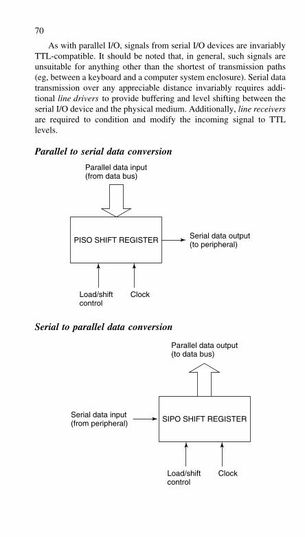
70
As with parallel I/O, signals from serial I/O devices are invariablyTTL-compatible. It should be noted that, in general, such signals areunsuitable for anything other than the shortest of transmission paths(eg, between a keyboard and a computer system enclosure). Serial datatransmission over any appreciable distance invariably requires addi-tional line drivers to provide buffering and level shifting between theserial I/O device and the physical medium. Additionally, line receiversare required to condition and modify the incoming signal to TTLlevels.
Parallel to serial data conversion
PISO SHIFT REGISTER Serial data output(to peripheral)
Parallel data input(from data bus)
Load/shiftcontrol
Clock
Serial to parallel data conversion
SIPO SHIFT REGISTERSerial data input(from peripheral)
Parallel data output(to data bus)
Load/shiftcontrol
Clock
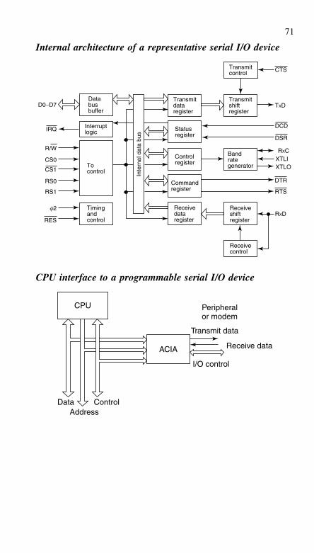
71
Internal architecture of a representative serial I/O device
Databusbuffer
Interruptlogic
Tocontrol
Timingandcontrol
D0−D7
IRQ
R/W
CS0
RS0
RS1
f2
CS1
RES
CTSTransmitcontrol
Transmitshiftregister
Transmitdataregister
Receivedataregister
Statusregister
Inte
rnal
dat
a bu
s
Controlregister
Commandregister
Receiveshiftregister
Receivecontrol
DCD
DSR
DTR
RTS
RXD
TXD
RXCXTLIXTLO
Bandrategenerator
CPU interface to a programmable serial I/O device
Address
ACIA
I/O control
Transmit data
Receive data
Peripheralor modem
CPU
Data Control
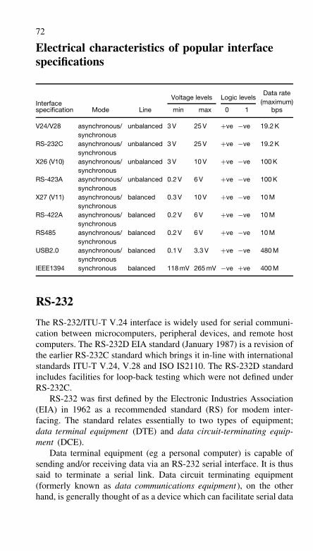
72
Electrical characteristics of popular interfacespecifications
Data rate
InterfaceVoltage levels Logic levels
(maximum)specification Mode Line min max 0 1 bps
V24/V28 asynchronous/synchronous
unbalanced 3 V 25 V +ve −ve 19.2 K
RS-232C asynchronous/synchronous
unbalanced 3 V 25 V +ve −ve 19.2 K
X26 (V10) asynchronous/synchronous
unbalanced 3 V 10 V +ve −ve 100 K
RS-423A asynchronous/synchronous
unbalanced 0.2 V 6 V +ve −ve 100 K
X27 (V11) asynchronous/synchronous
balanced 0.3 V 10 V +ve −ve 10 M
RS-422A asynchronous/synchronous
balanced 0.2 V 6 V +ve −ve 10 M
RS485 asynchronous/synchronous
balanced 0.2 V 6 V +ve −ve 10 M
USB2.0 asynchronous/synchronous
balanced 0.1 V 3.3 V +ve −ve 480 M
IEEE1394 synchronous balanced 118 mV 265 mV −ve +ve 400 M
RS-232
The RS-232/ITU-T V.24 interface is widely used for serial communi-cation between microcomputers, peripheral devices, and remote hostcomputers. The RS-232D EIA standard (January 1987) is a revision ofthe earlier RS-232C standard which brings it in-line with internationalstandards ITU-T V.24, V.28 and ISO IS2110. The RS-232D standardincludes facilities for loop-back testing which were not defined underRS-232C.
RS-232 was first defined by the Electronic Industries Association(EIA) in 1962 as a recommended standard (RS) for modem inter-facing. The standard relates essentially to two types of equipment;data terminal equipment (DTE) and data circuit-terminating equip-ment (DCE).
Data terminal equipment (eg a personal computer) is capable ofsending and/or receiving data via an RS-232 serial interface. It is thussaid to terminate a serial link. Data circuit terminating equipment(formerly known as data communications equipment), on the otherhand, is generally thought of as a device which can facilitate serial data
73
communications and a typical example is that of a modem (modulator-demodulator) which forms an essential link in the serial path betweena microcomputer and a conventional analogue telephone line.
An RS-232 serial port is usually implemented using a standard25-way D-connector. Data terminal equipment is normally fitted witha male connector while data circuit-terminating equipment conven-tionally uses a female connector (note that there are some exceptionsto this rule!).
RS-232 signals
RS-232 signals fall into one of the following three categories:
(a) data (eg, TXD, RXD)RS-232 provides for two independent serial data channels (describedas primary and secondary). Both of these channels provide for fullduplex operations (ie, simultaneous transmission and reception).
(b) handshake control (eg, RTS, CTS)Handshake signals provide the means by which the flow of serial datais controlled allowing, for example, a DTE to open a dialogue withthe DCE prior to actually transmitting data over the serial data path.
(c) timing (eg, TC, RC)For synchronous (rather than the more usual asynchronous) mode ofoperation, it is necessary to pass clock signals between the devices.These timing signals provide a means of synchronising the receivedsignal to allow successful decoding.
The complete set of RS-232D signals is summarised in the follow-ing table, together with EIA and ITU-T designations and commonlyused signal line abbreviations.
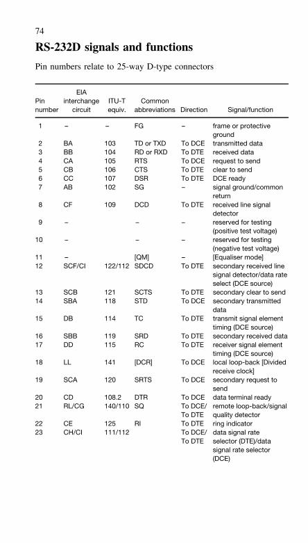
74
RS-232D signals and functions
Pin numbers relate to 25-way D-type connectors
Pinnumber
EIAinterchange
circuitITU-Tequiv.
Commonabbreviations Direction Signal/function
1 – – FG – frame or protectiveground
2 BA 103 TD or TXD To DCE transmitted data3 BB 104 RD or RXD To DTE received data4 CA 105 RTS To DCE request to send5 CB 106 CTS To DTE clear to send6 CC 107 DSR To DTE DCE ready7 AB 102 SG – signal ground/common
return8 CF 109 DCD To DTE received line signal
detector9 – – – reserved for testing
(positive test voltage)10 – – – reserved for testing
(negative test voltage)11 – [QM] – [Equaliser mode]12 SCF/CI 122/112 SDCD To DTE secondary received line
signal detector/data rateselect (DCE source)
13 SCB 121 SCTS To DTE secondary clear to send14 SBA 118 STD To DCE secondary transmitted
data15 DB 114 TC To DTE transmit signal element
timing (DCE source)16 SBB 119 SRD To DTE secondary received data17 DD 115 RC To DTE receiver signal element
timing (DCE source)18 LL 141 [DCR] To DCE local loop-back [Divided
receive clock]19 SCA 120 SRTS To DCE secondary request to
send20 CD 108.2 DTR To DCE data terminal ready21 RL/CG 140/110 SQ To DCE/
To DTEremote loop-back/signalquality detector
22 CE 125 RI To DTE ring indicator23 CH/CI 111/112 To DCE/ data signal rate
To DTE selector (DTE)/datasignal rate selector(DCE)
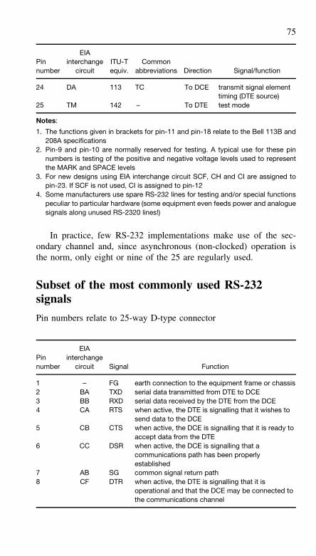
75
Pinnumber
EIAinterchange
circuitITU-Tequiv.
Commonabbreviations Direction Signal/function
24 DA 113 TC To DCE transmit signal elementtiming (DTE source)
25 TM 142 – To DTE test mode
Notes:
1. The functions given in brackets for pin-11 and pin-18 relate to the Bell 113B and208A specifications
2. Pin-9 and pin-10 are normally reserved for testing. A typical use for these pinnumbers is testing of the positive and negative voltage levels used to representthe MARK and SPACE levels
3. For new designs using EIA interchange circuit SCF, CH and CI are assigned topin-23. If SCF is not used, CI is assigned to pin-12
4. Some manufacturers use spare RS-232 lines for testing and/or special functionspeculiar to particular hardware (some equipment even feeds power and analoguesignals along unused RS-2320 lines!)
In practice, few RS-232 implementations make use of the sec-ondary channel and, since asynchronous (non-clocked) operation isthe norm, only eight or nine of the 25 are regularly used.
Subset of the most commonly used RS-232signals
Pin numbers relate to 25-way D-type connector
Pinnumber
EIAinterchange
circuit Signal Function
1 – FG earth connection to the equipment frame or chassis2 BA TXD serial data transmitted from DTE to DCE3 BB RXD serial data received by the DTE from the DCE4 CA RTS when active, the DTE is signalling that it wishes to
send data to the DCE5 CB CTS when active, the DCE is signalling that it is ready to
accept data from the DTE6 CC DSR when active, the DCE is signalling that a
communications path has been properlyestablished
7 AB SG common signal return path8 CF DTR when active, the DTE is signalling that it is
operational and that the DCE may be connected tothe communications channel
76
The table above gives the subset of commonly used RS-232 sig-nals. Note that the pin numbers relate to the 25-way connector. In the9-way connector, this subset is used but the pin numbers are different.
The most confusing difference between 25-way and 9-way connec-tors is that the functionality of pin numbers 2 and 3 are interchanged.Please compare the later diagrams ‘V.24/RS-232 interface connec-tions’ for the 25-way variety with the ‘V.24/RS-232 (9-pin) interfaceconnections’ for the 9-way variety.
RS-232 waveforms
In most RS-232 systems, data is transmitted asynchronously as a seriesof packets, each representing a single ASCII character and containingsufficient information for it to be decoded without the need for aseparate clock signal.
ASCII characters are represented by seven binary digits (bits).The upper case letter A, for example, is represented by the seven-bitbinary word; 1000001. In order to send the letter A via an RS-232system, we need to add extra bits to signal the start and end of thedata packet. These are known as the start bit and stop bit respectively.In addition, we may wish to include a further bit to provide a simpleparity error detecting facility.
One of the most commonly used schemes involves the use ofone start bit, one parity bit, and two stop bits. The commencementof the data packet is signalled by the start bit which is always lowirrespective of the contents of the packet. The start bit is followedby the seven data bits representing the ASCII character concerned. Aparity bit is added to make the resulting number of 1s in the groupeither odd (odd parity) or even (even parity). Finally, two stop bitsare added. These are both high.
The complete asynchronously transmitted data word thus com-prises eleven bits (not that only seven of these actually contain data).In binary terms the word can be represented as: 01000001011. In thiscase, even parity has been used and thus the ninth (parity bit) is a 0.
Voltage levels employed in an RS-232 interface are markedly dif-ferent from those used within a microcomputer system. A positivevoltage (of between +3 V and +25 V) is used to represent a logic 0(or space) while a negative voltage (of between −3 V and −25 V) isused to represent a logic 1 (or mark ).
Level shifting (from TTL to RS-232 signal levels and vice versa)is invariably accomplished using line driver and line receiver chips,the most common examples being the 1488 and 1489 devices.
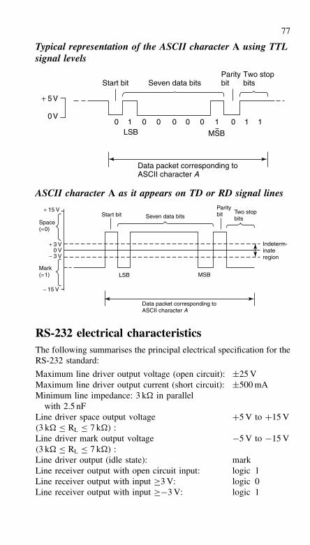
77
Typical representation of the ASCII character A using TTLsignal levels
0 0 0 0 0 0 11 1 100V
+ 5V
Start bit Seven data bits
LSB
Paritybit
Two stopbits
Data packet corresponding toASCII character A
MSB
ASCII character A as it appears on TD or RD signal lines
+ 15 V
− 15 V
− 3 V
+ 3 V0 V
LSBMark(=1)
Space(=0)
Start bit
MSB
Seven data bits
Data packet corresponding toASCII character A
Paritybit Two stop
bits
Indeterm-inateregion
RS-232 electrical characteristicsThe following summarises the principal electrical specification for theRS-232 standard:
Maximum line driver output voltage (open circuit): ±25 VMaximum line driver output current (short circuit): ±500 mAMinimum line impedance: 3 k� in parallel
with 2.5 nFLine driver space output voltage(3 k� ≤ RL ≤ 7 k�) :
+5 V to +15 V
Line driver mark output voltage(3 k� ≤ RL ≤ 7 k�) :
−5 V to −15 V
Line driver output (idle state): markLine receiver output with open circuit input: logic 1Line receiver output with input ≥3 V: logic 0Line receiver output with input ≥−3 V: logic 1
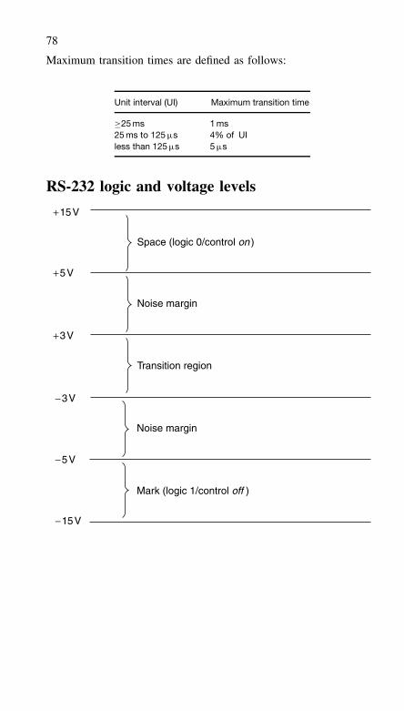
78
Maximum transition times are defined as follows:
Unit interval (UI) Maximum transition time
≥25 ms 1 ms25 ms to 125 µs 4% of UIless than 125 µs 5 µs
RS-232 logic and voltage levels
+3V
+5V
+15V
Space (logic 0/control on )
Noise margin
Transition region
−5V
−3V
−15V
Mark (logic 1/control off )
Noise margin
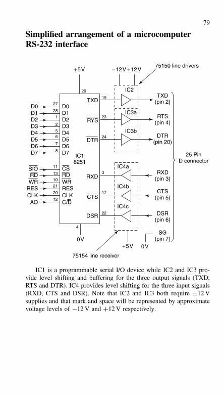
79
Simplified arrangement of a microcomputerRS-232 interface
0V0V
D0D1D2D3D4D5D6D7
D0D1D2D3D4D5D6D7
SIORDWR WR
RES RESCLK CLKAO
CSRD
C/DCTS
DSR
DTR
RYS
TXD
RXD
75150 line drivers+12V+5V
+5V
−12V
19
23
24
3
17
22
DTR(pin 20)
RTS(pin 4)
TXD(pin 2)
RXD(pin 3)
CTS(pin 5)
DSR(pin 6)
SG(pin 7)
75154 line receiver
26 IC2
IC3a
IC3b
IC4a
IC4b
IC4c
IC18251
25 PinD connector
27
28
1
2
56
7
8
11
13
10
21
20
12
4
IC1 is a programmable serial I/O device while IC2 and IC3 pro-vide level shifting and buffering for the three output signals (TXD,RTS and DTR). IC4 provides level shifting for the three input signals(RXD, CTS and DSR). Note that IC2 and IC3 both require ±12 Vsupplies and that mark and space will be represented by approximatevoltage levels of −12 V and +12 V respectively.
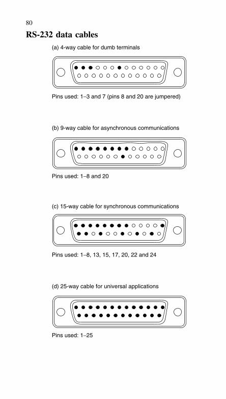
80
RS-232 data cables(a) 4-way cable for dumb terminals
Pins used: 1−3 and 7 (pins 8 and 20 are jumpered)
Pins used: 1−8 and 20
Pins used: 1−8, 13, 15, 17, 20, 22 and 24
Pins used: 1−25
(b) 9-way cable for asynchronous communications
(c) 15-way cable for synchronous communications
(d) 25-way cable for universal applications
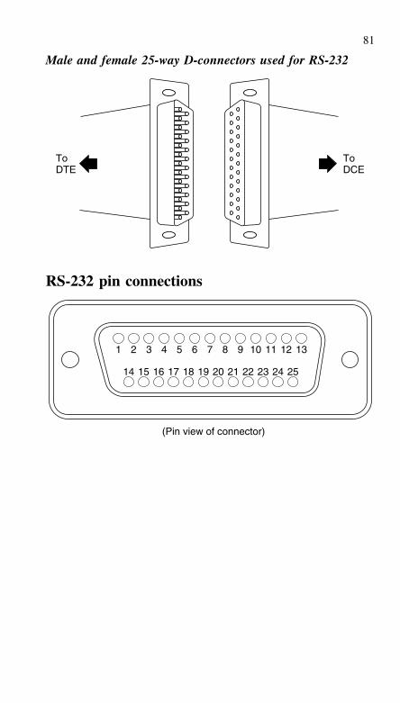
81
Male and female 25-way D-connectors used for RS-232
ToDTE
ToDCE
RS-232 pin connections
1 2 3 4 5 6 7 8 9 10 11 12 13
14 15 16 17 18 19 20 21 22 23 24 25
(Pin view of connector)
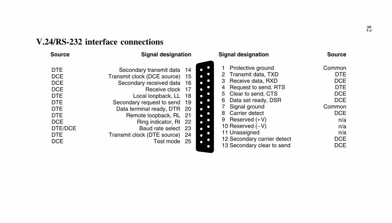
82
V.24/RS-232 interface connectionsSource Signal designation Signal designation Source
DTEDCEDCEDCEDTEDTEDTEDTEDCEDTE/DCEDTEDCE
Secondary transmit data 14 Transmit clock (DCE source) 15
Secondary received data 16Receive clock 17
Local loopback, LL 18 Secondary request to send 19
Data terminal ready, DTR 20Remote loopback, RL 21
Ring indicator, RI 22Baud rate select 23
Transmit clock (DTE source) 24Test mode 25
Common
Common
DTE
DTEDCE
DCEDCE
DCEn/an/an/a
DCE
1 Protective ground
7 Signal ground
2 Transmit data, TXD
4 Request to send, RTS3 Receive data, RXD
5 Clear to send, CTS6 Data set ready, DSR
8 Carrier detect9 Reserved (+V)10 Reserved (−V)11 Unassigned12 Secondary carrier detect13 Secondary clear to send DCE
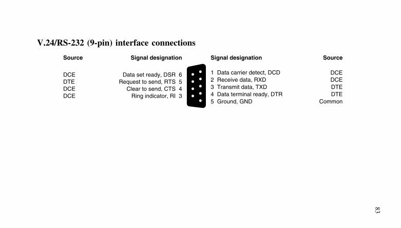
83
V.24/RS-232 (9-pin) interface connections
Signal designation Signal designation
1 Data carrier detect, DCD
Source Source
Data set ready, DSR 6DCERequest to send, RTS 5DTE
Clear to send, CTS 4DCERing indicator, RI 3DCE
5 Ground, GND Common
2 Receive data, RXD DCE
4 Data terminal ready, DTR DTE3 Transmit data, TXD DTE
DCE
84
RS-232 enhancements
Several further standards have been introduced in order to overcomesome of the shortcomings of the original RS-232 specification. Thesegenerally provide for better line matching, increased distance capabil-ity, and faster data rates. Notable among these systems are RS-422 (abalanced system which caters for a line impedance as low as 50 ohm),RS-423 (an unbalanced system which will tolerate a line impedanceof 450 ohm minimum), and RS-449 (a very fast serial data standardwhich uses a number of changed circuit functions and a 37-way Dconnector).
RS-422
RS-422 is a balanced system (differential signal lines are used) whichemploys lower line voltage levels than those employed with RS-232.Space is represented by a line voltage level in the range +2 V to +6 Vwhile mark is represented by a line voltage level in the range −2 Vto −6 V. RS-422 caters for a line impedance of as low as 50 ohm andsupports data rates of up to 10 Mbps.
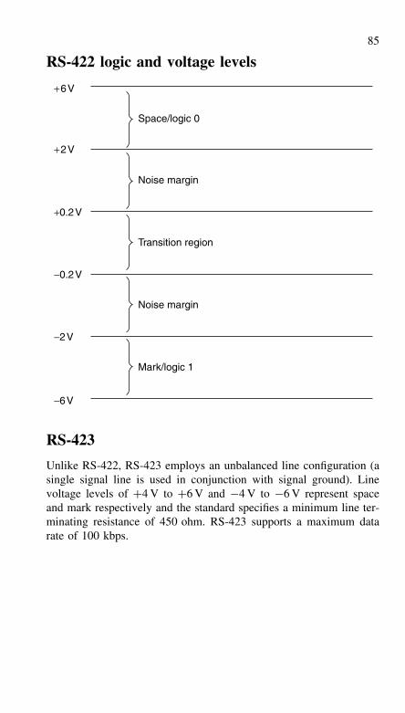
85
RS-422 logic and voltage levels
+0.2V
+2V
+6V
Space/logic 0
Noise margin
Transition region
−0.2V
Noise margin
−2V
−6V
Mark/logic 1
RS-423
Unlike RS-422, RS-423 employs an unbalanced line configuration (asingle signal line is used in conjunction with signal ground). Linevoltage levels of +4 V to +6 V and −4 V to −6 V represent spaceand mark respectively and the standard specifies a minimum line ter-minating resistance of 450 ohm. RS-423 supports a maximum datarate of 100 kbps.
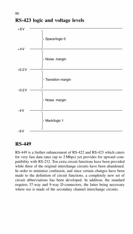
86
RS-423 logic and voltage levels
+0.2V
+4V
+6V
Space/logic 0
Noise margin
Transition margin
−0.2V
Noise margin
−4V
Mark/logic 1
−6V
RS-449
RS-449 is a further enhancement of RS-422 and RS-423 which catersfor very fast data rates (up to 2 Mbps) yet provides for upward com-patibility with RS-232. Ten extra circuit functions have been providedwhile three of the original interchange circuits have been abandoned.In order to minimise confusion, and since certain changes have beenmade to the definition of circuit functions, a completely new set ofcircuit abbreviations has been developed. In addition, the standardrequires 37-way and 9-way D-connectors, the latter being necessarywhere use is made of the secondary channel interchange circuits.
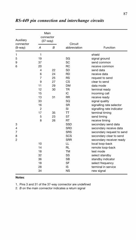
87
RS-449 pin connection and interchange circuits
Main
Auxiliaryconnector
connector(37-way)
Circuit(9-way) A B abbreviation Function
1 1 shield5 19 SG signal ground9 37 SC send common6 20 RC receive common
4 22 SD send data6 24 RD receive data7 25 RS request to send9 27 CS clear to send
11 29 DM data mode12 30 TR terminal ready15 IC incoming call13 31 RR receive ready33 SQ signal quality16 SR signalling rate selector2 SI signalling rate indicator
17 35 TT terminal timing5 23 ST send timing8 26 RT receive timing
3 SSD secondary send data4 SRD secondary receive data7 SRS secondary request to send8 SCS secondary clear to send2 SRR secondary receiver ready
10 LL local loop-back14 RL remote loop-back18 TM test mode32 SS select standby36 SB standby indicator18 SF select frequency28 IS terminal in service34 NS new signal
Notes:
1. Pins 3 and 31 of the 37-way connector are undefined2. B on the main connector indicates a return signal
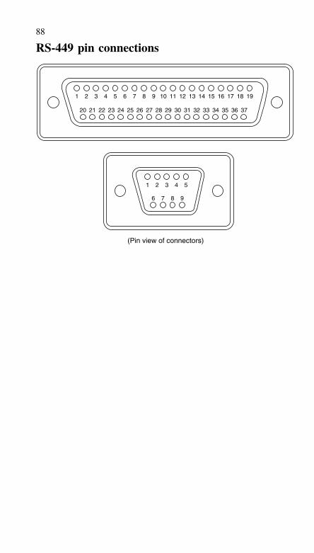
88
RS-449 pin connections
(Pin view of connectors)
1 2 3 4 5
1 2 3 4 5
6 7 8 9
6 7 8 9
10 11 12 13 14 15 16 17 18 19
20 21 22 23 24 25 26 27 28 29 30 31 32 33 34 35 36 37

89
V.36/RS-449 interface connectionsSignal designation Signal designation Source
Send common 37Standby indicator 36
Terminal timing (B) 35New signal 34
Signal quality 33Select standby 32
Receiver ready (B) 31Terminal ready (B) 30
Data mode (B) 29Terminal in service 28
19 Signal ground18 Test mode17 Terminal timing (A)16 Select frequency15 Incoming call14 Remote loopback13 Receiver ready (A)12 Terminal ready (A)11 Data mode (A)10 Local loopback9 Clear to send (A)8 Receive timing (A)7 Request to send (A)6 Receive data (A)5 Send timing (A)4 Send data (A)3 Unassigned2 Signal rate indicator1 Shield
Clear to send (B) 27Receive timing (B) 26
Request to send (B) 25 Receive data (B) 24
Send timing (B) 23Send data (B) 22
Unassigned 21Receive common 20
Common
DCE
DCE
DTEDTE
DCEDTE
DTEDCEDTEDCEDCEDTEDCEDCEDTE
n/aDCE
Common
Source
Common
Return
DCE
DTEReturn
DTCDTE
ReturnReturnDTEReturnReturnReturnReturnReturnReturnn/aCommon
90
RS-485
The Electronic Industries Association (EIA) and the Telecommunica-tions Industry Association (TIA) jointly developed the RS-485 stan-dard. Strictly, this should now be referred to as EIA/TIA-485.
RS-485 is closely related to the RS-422 standard, with balancedline transmission. RS-422 has one driver and a number of receivers: thedriver is always active on the line. But RS-485 allows bi-directionalhalf-duplex operation, with one driver connected at each end of thecable pair. Driver and receiver pairs can be located at various pointsalong the bus, but only one driver can be active at any one time. Theunused driver is put into the high-impedance state, so that it does notaffect the data signals transmitted from the other end of the link. Partsintended for RS-485 can also be used for RS-422, but the reverse isnot true because RS-422 drivers cannot relinquish control of the bus.
The bus should be one continuous pair with a 120-ohm terminatingresistor at either end. An alternative ‘fail-safe’ bus termination has a130-ohm terminating resistor, a 750-ohm ‘pull-up’ resistor from theA-wire to +5 V and a 750-ohm ‘pull-down’ resistor from the B-wireto ground. Spurs off the bus should not be allowed, unless the systemoperates at low-speed, because reflections from an unterminated spurwill affect the data pulse shape and cause errors. The bus can be upto 1250 metres long, at data rates of up to 100 kbps. At higher datarates the maximum line length is reduced. At 10 Mbps, the maximumline length is about 30 metres.
RS-485 logic levels and connectors
The RS-485 logic and voltage levels are the same as those previouslygiven for RS-422. Each receiver has a maximum threshold of 200 mV.The minimum output level from any driver is 1.5 V.
There is no connector, cable or protocol specification for RS-485.
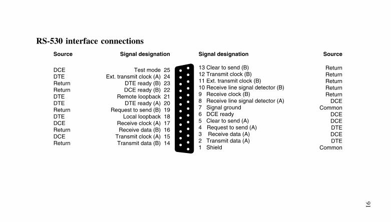
91
RS-530 interface connectionsSignal designation Signal designation Source
Test mode 25Ext. transmit clock (A) 24
DTE ready (B) 23DCE ready (B) 22
Remote loopback 21DTE ready (A) 20
Request to send (B) 19Local loopback 18
Receive clock (A) 17Receive data (B) 16
13 Clear to send (B)12 Transmit clock (B)11 Ext. transmit clock (B)10 Receive line signal detector (B)9 Receive clock (B)8 Receive line signal detector (A) 7 Signal ground6 DCE ready5 Clear to send (A)4 Request to send (A)3 Receive data (A)2 Transmit data (A)1 Shield
Transmit clock (A) 15Transmit data (B) 14
Return
Common
Return
ReturnReturn
ReturnDCE
DCEDCEDTEDCEDTE
Common
Source
DCE
Return
DTE
ReturnReturn
DTEDTE
DTEDCEReturnDCEReturn
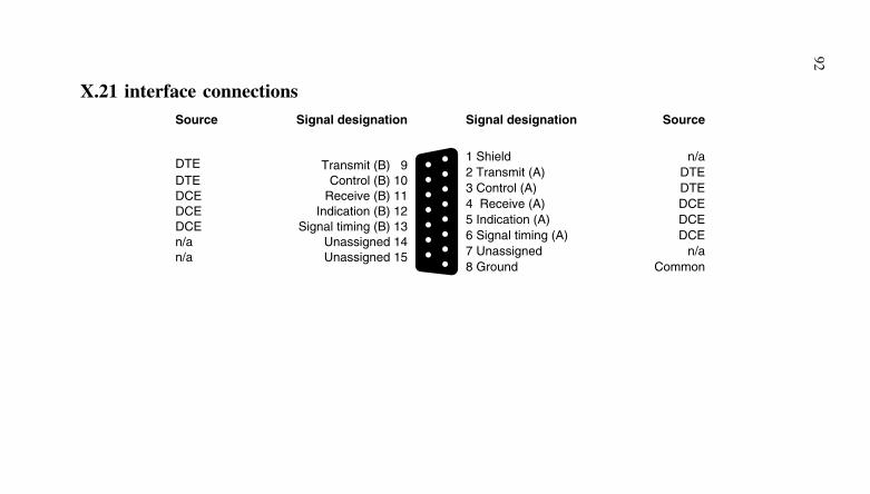
92
X.21 interface connectionsSignal designation Signal designation Source
Transmit (B) 91 Shield n/a
7 Unassigned n/a
2 Transmit (A) DTE
4 Receive (A) DCE3 Control (A) DTE
5 Indication (A) DCE6 Signal timing (A) DCE
8 Ground Common
Source
DTE
Unassigned 15n/a
Control (B) 10DTE
Indication (B) 12DCEReceive (B) 11DCE
Signal timing (B) 13DCEUnassigned 14n/a
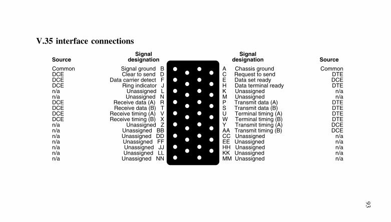
93
V.35 interface connections
Signal ground BClear to send D
Data carrier detect FRing indicator J
Unassigned LUnassigned N
Receive data (A) RReceive data (B) T
Receive timing (A) VReceive timing (B) X
Unassigned ZUnassigned BBUnassigned DDUnassigned FFUnassigned JJUnassigned LL
Unassigned NN
A Chassis groundC Request to sendE Data set readyH Data terminal readyK UnassignedM UnassignedP Transmit data (A)S Transmit data (B)U Terminal timing (A)W Terminal timing (B)Y Transmit timing (A)AA Transmit timing (B)CC UnassignedEE UnassignedHH UnassignedKK UnassignedMM Unassigned
CommonDTEDCEDTE
n/an/a
DTEDTEDTEDTEDCEDCE
n/an/an/an/an/a
CommonDCEDCEDCEn/an/aDCEDCEDCEDCEn/an/an/an/an/an/an/a
Source SourceSignal
designationSignal
designation
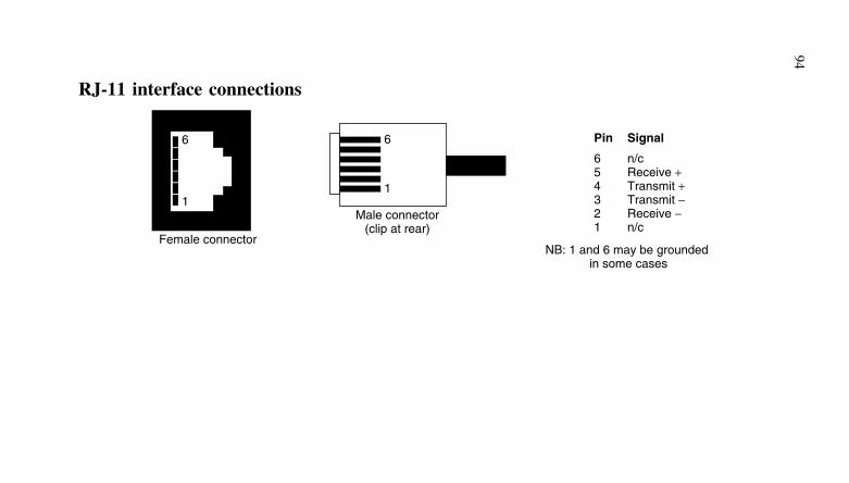
94
RJ-11 interface connections
6
1
Female connector
6
1
Male connector(clip at rear)
Pin
654321
Signal
n/cReceive +Transmit +Transmit −Receive −n/c
NB: 1 and 6 may be grounded in some cases
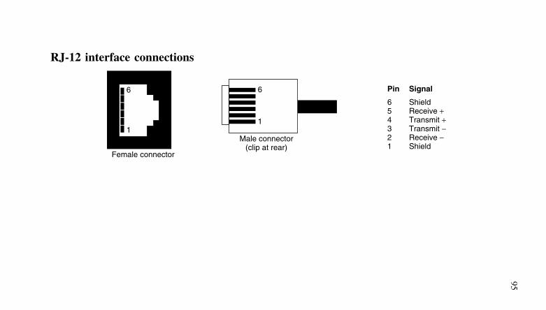
95
RJ-12 interface connections
6
1
Female connector
6
1
Male connector(clip at rear)
Pin
654321
Signal
ShieldReceive +Transmit +Transmit −Receive −Shield
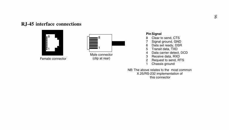
96
RJ-45 interface connections
8
1
8
1
Female connectorMale connector
(clip at rear)
NB: The above relates to the most commonX.25/RS-232 implementation of
this connector
Pin87654321
SignalClear to send, CTSSignal ground, GNDData set ready, DSRTransit data, TXDData carrier detect, DCDReceive data, RXDRequest to send, RTSChassis ground
97
USB
The purpose of USB is to replace most of the traditional ports ona PC a single versatile and user-friendly interface. USB is a sharedserial bus using defined protocols. Most of the interface intelligenceis placed in the host computer, allowing the use of less complex andless expensive peripherals. It was intended to be a desktop bus forstandard peripherals, but USB is now an option for most devices thatwere previously connected by an RS-232 or parallel port.
There are two versions of USB. Version 1.x supports two busspeeds: full-speed at 12 Mbps and low-speed at 1.5 Mbps. Low-speeddata rates target cost-sensitive peripherals, as well as mice and otherdevices that require unshielded flexible cables. USB 2.0 also supportshigh-speed at 480 Mbps, which opens the interface to new applica-tions.
Physically, the bus comprises four wires: two for power and twofor data. The USB connector therefore has four pins. Pin 1 connects to+5 V, pin 2 connects to D+, pin 3 connects to D− and pin 4 connectsto 0 V (ground). The PC host and self-powered peripherals (such asa printer) provide a current limited power source. Thus peripherals(such as a PC’s mouse) can be powered over the USB bus. By usingall four wires for each peripheral, power feeding the network of non-powered peripherals is shared between the powered devices. Also,using a PC as a power source, a non-powered keyboard can relaypower to attached peripherals such as a mouse and a joystick.
The cable used to connect low-speed devices in a USB version1.1-compliant system requires no shielding. If a USB 2.0 interfaceis low-speed, it must meet new shielding requirements. A USB 2.0-compliant low-speed cable must have the same aluminium-metallised-polyester inner shield and copper drain wire required for full- andhigh-speed cables. A braided outer shield and a twisted pair for dataare also recommended, as used on full- and high-speed cables.
High-speed USB 2.0 buses allow the use of low- and full-speeddevices while transferring data at high-speed whenever possible. Ona full-speed bus, the host controller divides the bus time into frames,each 1 ms long. Every frame begins with an SOF (start-of-frame)packet that devices use as a timing reference. Within each frame,the host can schedule multiple transactions to multiple destinations.Each transaction includes an endpoint address that identifies the devicebuffer to be used. In most transaction types, information travels in bothdirections. The host initiates the transaction, data travels to or fromthe host, and then the receiving destination returns status information.
98
For high-speed traffic, the host divides each frame into eightmicroframes, each beginning with an SOF packet. Each microframecan carry multiple transactions to multiple destinations. Comparedwith full-speed, individual transactions can carry more data. USBversion 2.0 protocol enhancements make better use of the bus at allspeeds.
Hubs can increase the number of ports available to peripherals. Atypical hub has one upstream port that transmits toward and receivesfrom the host and as many as seven downstream ports that can con-nect to peripherals or additional hubs. A 1.x hub supports both low-and full-speed data rates but does not convert between speeds; it justpasses the traffic on, changing only the edge rate to match the des-tination’s speed. A 2.0 hub acts as a remote processor and convertsfrom high-speed data to low- or full-speed data as needed.
A USB version 1.x hub determines a device’s speed by detectingthe voltages on the D+ and D− signal wires from the device. If D−is pulled up at the device, its USB interface is low-speed, and the hubpasses only low-speed traffic to the device. In the other direction, thehub passes all the traffic that it receives from the low-speed device tothe host. If D+ is pulled up at the device, the device’s USB interfaceis full-speed, and the hub passes low- and full-speed traffic in bothdirections.
If a low- or full-speed device is connected to a hub that is receivinghigh-speed data from upstream, a transaction translator in the hubconverts the data to low- or full-speed before passing it on. In the otherdirection, the hub converts low- or full-speed data to high speed beforesending it toward the host. To reduce jitter, the hub re-synchronisesreceived high-speed data but otherwise passes it unchanged to anyattached high-speed devices.
USB supports four data transfer types:
• Control transfers are for enumeration and other times when thehost wants to send defined requests and (optionally) receive data inreply.
• Interrupt transfers are for pointing devices and other applicationsthat need to transfer data at intervals, with a guaranteed maximumtime between transactions.
• Bulk transfers are for printers, scanners, and other devices thatwould like to transfer data as quickly as possible but can wait ifthe bus is busy.
• Isochronous transfers are for real-time audio and other applicationsthat require guaranteed delivery time but need no error correctingin the transfer.
99
A USB transaction consists of two or more packets. To begina transaction, the host sends a token packet containing informationabout the transaction. A transaction must also have a data packet, ahandshake packet where the receiver of the data returns status infor-mation, or both. (If no data packet exists, the device sends the statusinformation.)
In addition to the high-speed bit rate, USB 2.0 has an improvedprotocol for high-speed transfers and new split transactions for full-and low-speed transfers on high-speed buses. For bulk and isochronoustransfers, high-speed transfers are about 40 times faster than full-speedtransfers are, simply because the bus speed is 40 times faster. But ahigh-speed interrupt transfer can be almost 400 times faster. Tworeasons exist for this speed increase: The maximum packet size pertransaction is much greater, and a transaction can have multiple datapackets in a frame. High-speed control transfers are also much fasterbecause they can transfer more data per frame.
For high-speed bulk and control transfers, 2.0 supports animproved protocol that uses less bus time to determine whether adevice is ready to receive data. With full- and low-speed devices,when the host wants to send data in a control, bulk, or interrupttransfer, it sends the token and data packets and receives a reply fromthe device in the handshake packet of the transaction. If the deviceisn’t ready for the data, it returns a NAK (negative acknowledgment),and the host tries again later. This protocol can waste a lot of bustime if the device is rarely ready.
High-speed bulk and control transactions have a better handshak-ing method. After receiving data, a device endpoint can return a NYET(not yet) handshake, which says that the endpoint accepted the data,but it is not yet ready to receive more data. When the host thinks thedevice might be ready, it sends a PING token packet, and the end-point returns an ACK (acknowledge) or a NAK to indicate whetherthe host can send the next transaction’s data.
To efficiently use bus time, high-speed hosts and hubs use newsplit transactions with low- and full-speed devices. At low- and full-speed, all of a transaction’s packets are in sequence, with no othertraffic between them. For example, on receiving token and data pack-ets, a device must return an expected handshake packet without delay.But a high-speed hub could waste a lot of time waiting for a low- orfull-speed device to receive the token and data packets and return aresponse.
Two part transactions are used to reduce wasted time. At high-speeds, the host sends the hub a start-split token packet along with
100
any data the host is sending in the transaction. The host is then free todo other transactions without waiting for this transaction to complete.The high-speed hub then translates to low- or full-speed and completesthe transaction with the destination device. However, instead of thehub passing on the device’s response to the host immediately uponreceipt, it stores the response in a buffer. Later, the host sends acomplete-split token packet to request the device’s response from thehub. The hub returns the data or handshake packet and completes thetransaction with the host.
USB receivers detect a differential 0 or 1 by measuring whetherthe D+ or D− input is more positive. The voltage on each line mustalso be within a specified, absolute range. Transceivers must haveseparate drivers for high speed. For receiving, transceivers may haveone pair of receivers that handles all speeds or separate receivers forhigh speeds.
In a high-speed driver, a current source drives one line, with theother line at ground. To conserve power, a high-speed driver canactivate its current source only when transmitting. This approach com-plicates the design, however, because the spec requires the device tomeet amplitude and timing requirements from the very first symbol ina packet. So the spec also allows the driver to keep its current sourceactive at all times, directing the current to ground when the device isnot transmitting on the bus.
In a transceiver that is capable of high-speed data rates, the outputimpedance of the full-speed drivers has less tolerance (45 ohm, ±10%compared with 36 ohm, ±22%). The change is necessary because thehigh-speed bus uses the full-speed drivers to terminate the line.
When the high-speed drivers are active, the full-speed driversbring both data lines low (USB’s single-ended zero state), resultingin each driver and its series resistor providing a 45 ohm terminationto ground. These terminations at both the source and load quiet theline more effectively than the source-only terminations on a full-speedcable segment. The series resistors may be on- or off-chip. Drivers thataren’t part of a high-speed transceiver require no changes in outputimpedance.
In a low- or full-speed device, a 1.5-kohm pull-up resistor onone of the signal lines indicates device speed. Both wires also have15-kohm pull-down resistors at the hub. At high speeds, the pull-downs remain, but not the pull-up. When a device switches to highspeed, it must remove the pull-up from the line.
When you attach a low- or full-speed device to the bus or removeone from the bus, the voltage change due to the pull-up informs the
101
hub of the change. High-speed devices always attach at full speed, sothe hub detects these devices in the usual way.
The switch to high speed occurs during the reset signal, whichthe hub sends after it detects the device. A device that is capableof supporting high-speed data rates must support the new high-speedhandshake that informs the hub that the device can handle high speedsand switches to high speed if possible.
The hub must also detect the removal of a high-speed device,which has no pull-up. It does so by checking the voltage during theEOP (end-of-packet) signal in each high-speed SOF packet. When youremove a device from the bus, you remove its differential terminations,doubling the voltage at the hub’s port. When the hub detects thedoubled voltage, it knows that the device has been removed.
IEEE-1355
IEEE-1355 is an all-purpose inter-connect standard and is intended forshort distances (tens of metres) like RS-232. It requires a UART typedevice and can operate at data rates from 1 Mbps to 1 Gbps, or more.
IEEE-1355 uses ATM-like packets with an address header todescribe the path or channel required. The routing of each packetthrough the network uses a packet switch.
IEEE-1394 ‘Firewire’
USB’s high-speed competitor is IEEE-1394, also known as Firewire.IEEE-1394 has a bus speed of 400 Mbps, and IEEE-1394b proposesto increase this rate to 3.2 Gbps. Note that the two buses have differ-ent purposes, although some peripherals could use either device. WithUSB, the host initiates every transfer, and every transfer has one des-tination. With IEEE-1394, peripherals can communicate directly witheach other, and a transfer can have multiple destinations. IEEE-1394devices require more intelligence to manage their communications, sotheir peripheral controllers are more complex and expensive.
The IEEE-1394 bus uses special connectors with six connectionpins. The first two pins are for power: Pin 1 is V+ and pin 2 isground. Pins 3 and 4 are for transmit data (strobe on receive). Pins 5and 6 are for receive data (strobe on transmit). Thus pins 3 and 4 atone end of a cable are connected to pins 5 and 6, respectively, at theother end of the cable.
The IEEE-1394 bus is limited to connecting 63 devices. Eachdevice has multiple bus connections, allowing devices to communicate
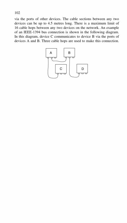
102
via the ports of other devices. The cable sections between any twodevices can be up to 4.5 metres long. There is a maximum limit of16 cable hops between any two devices on the network. An exampleof an IEEE-1394 bus connection is shown in the following diagram.In this diagram, device C communicates to device B via the ports ofdevices A and B. Three cable hops are used to make this connection.
A B
C D
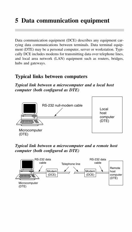
5 Data communication equipment
Data communication equipment (DCE) describes any equipment car-rying data communications between terminals. Data terminal equip-ment (DTE) may be a personal computer, server or workstation. Typi-cally DCE includes modems for transmitting data over telephone lines,and local area network (LAN) equipment such as routers, bridges,hubs and gateways.
Typical links between computers
Typical link between a microcomputer and a local hostcomputer (both configured as DTE)
Microcomputer(DTE)
RS-232 null-modem cableLocalhostcomputer(DTE)
Typical link between a microcomputer and a remote hostcomputer (both configured as DTE)
Telephone line
RS-232 datacable
Modem(DCE)
Modem(DCE)
Remotehostcomputer(DTE)
RS-232 datacable
Microcomputer(DTE)
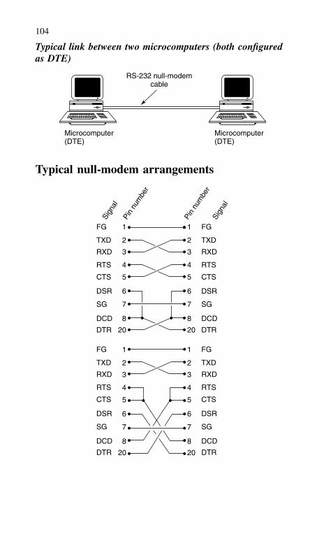
104
Typical link between two microcomputers (both configuredas DTE)
RS-232 null-modemcable
Microcomputer(DTE)
Microcomputer(DTE)
Typical null-modem arrangements
1 1
2 2
3 3
4 4
5 5
6 6
7 7
8 8
20
FG
TXD
RXD
RTS
CTS
DSR
SG
DCD
DTR
FG
TXD
RXD
RTS
CTS
DSR
SG
DCD
DTR
FG
TXD
RXD
RTS
CTS
DSR
SG
DCD
DTR
FG
TXD
RXD
RTS
CTS
DSR
SG
DCD
DTR
20
1 1
2 2
3 3
4 4
5 5
6 6
7 7
8 8
20 20
Sign
al
Sign
al
Pin
num
ber
Pin
num
ber
105
Modems
The name modem is a contraction of modulator–demodulator andthis succinctly describes the function of a device that has the dualrole of:
• Modulating an outgoing baseband signal onto a carrier for trans-mission through a physical medium
• Demodulating an incoming modulated carrier from the physicalmedium in order to recover an input baseband signal.
The modulation method employed in the simplest modems (such asV.21) is frequency shift keying (FSK). A sinusoidal signal of onefrequency represents a space (logic 0) and that another frequencyrepresents a mark (logic 1). The frequencies used for the mark andspace tones are chosen so that they can be passed through the trans-mission medium with minimal attenuation. Hence, in the case ofmodems used with ordinary telephone lines, both mark and spacemust be represented by audible tones in the frequency range 300 Hzto 3.4 kHz.
The available bandwidth within the transmission medium (tele-phone line) also has a bearing upon the signalling rate. A widerbandwidth will permit signalling (i.e. switching between mark andspace tones) at a faster rate. In practice, the maximum signallingrate for FSK modems transmitting over a conventional exchangeline is in the region of 1300 baud. It is, however, possible for asingle exchange line to support duplex working in which case dif-ferent mark and space frequencies must be employed for transmit andreceive.
Filters are used within FSK modems to separate transmit andreceive frequencies and each end of the link must employ a differentpair of mark and space frequencies. The frequencies used for settingup a data transfer (i.e. those used for originate mode) will thus bedifferent from those which are used in response to such a request (i.e.those used in answer mode). When communication is established witha larger remote host, the user-modem will normally establish the callin originate mode.
Medium-speed modems use more complex modulation methods.Phase modulation is used by V.22/Bell 212 (1200 baud full duplex)
106
and V.26/Bell 201 (2400 baud full duplex) modems. In both types ofmodem an 1800 Hz carrier signal is phase modulated, with 90, 180 or270 degree phase shifts to indicate the data. Each phase shift signalsthe state of two data bits.
A slightly higher speed modem standard is V.27, which operatesat 4800 baud. A V.27 modem uses one of eight possible phase shifts,each 45 degrees apart, to signal three data bits. Thus no phase changerepresents 001, a 45 degree change represents 000, a 90 degree changerepresents 010, etc.
The highest speed telephone line modems use both amplitude andphase modulation (known as quadrature amplitude modulation, orQAM) with trellis encoding. V.34 modems operate at up to 33.6 kbps.A variant on V.34 is V.90, which uses DC levels from the exchangerather than tones to signal the remote modem. Each DC level is usedto indicate up to 7 data bits. A V.90 modem uses V.34 signalling inthe remote modem to exchange direction.
In medium and high-speed modems, both transmit and receivedata are transmitted using the same 1800 Hz carrier frequency. Inorder to allow full duplex working, echo cancellation is used in themodem to separate received signals from locally generated signals.Thus only the carrier signal received over the telephone line entersthe demodulator circuit.
Signal frequencies are governed by a number of internationallyagreed (ITU-T) standards in the V-series. It is rare for low-speedmodems like V.21 to be used, but V.34 and V.90 are popular. The lat-est high-speed modem is V.92, with 56 kbps from the exchange and upto 44 kbps from the modem. Most modern modems are able to supporta number of standards as well as providing auto-originate/auto-answerfacilities. A modem will sometimes revert to a lower speed if thetransmission path cannot support the highest speeds.
Communications software is normally required to set up the serialport to which the modem is connected (via RS-232) and, in manycases also to configure the modem. Software will generally providefor a range of signalling speeds (baud rates) and handshaking protocols(e.g. X-ON/X-OFF).
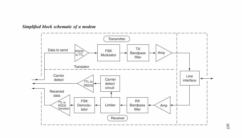
107
Simplified block schematic of a modem
AmpTX
Bandpassfilter
FSKModulator
Transmitter
Receiver
Data to send RS232to TTL
Carrierdetect
Receiveddata
TTL toRS232Translator
TTL toRS232
Carrierdetectcircuit
Lineinterface
AmpRX
Bandpassfilter
LimiterFSK
Demodu-lator
Translator
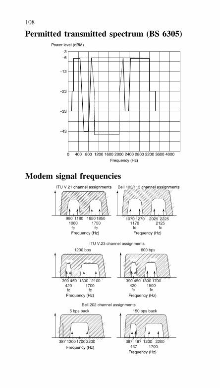
108
Permitted transmitted spectrum (BS 6305)
0 400 800 1200 1600 2000
Frequency (Hz)
2400 2800 3200 3600 4000
−3
Power level (dBM)
−13
−23
−33
−43
−6
Modem signal frequenciesITU V.21 channel assignments Bell 103/113 channel assignments
Frequency (Hz)Frequency (Hz)
Frequency (Hz) Frequency (Hz)
Frequency (Hz)Frequency (Hz)
980 1070 1270 2025 22252125
fc1170
fc1080
fc
1200 bps
390 450 1300
fc
1700390420fc
150 bps back
1500450 1300 2100
420 1700fc fc
600 bps
1180 16501750
fc
ITU V.23 channel assignments
1850
Bell 202 channel assignments
5 bps back
387 1200 1700 2200 387437 1700
487 1200 2200
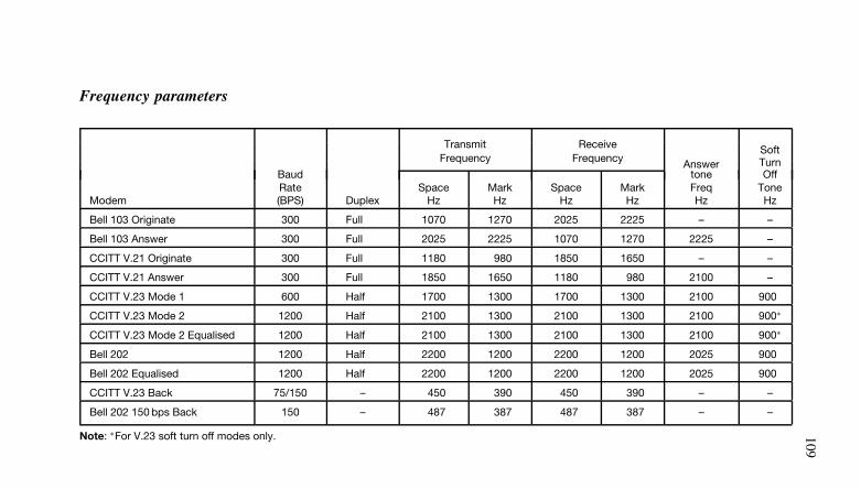
109
Frequency parameters
Transmit Receive SoftFrequency Frequency Answer Turn
Baud tone OffRate Space Mark Space Mark Freq Tone
Modem (BPS) Duplex Hz Hz Hz Hz Hz Hz
Bell 103 Originate 300 Full 1070 1270 2025 2225 – –
Bell 103 Answer 300 Full 2025 2225 1070 1270 2225 –
CCITT V.21 Originate 300 Full 1180 980 1850 1650 – –
CCITT V.21 Answer 300 Full 1850 1650 1180 980 2100 –
CCITT V.23 Mode 1 600 Half 1700 1300 1700 1300 2100 900
CCITT V.23 Mode 2 1200 Half 2100 1300 2100 1300 2100 900∗
CCITT V.23 Mode 2 Equalised 1200 Half 2100 1300 2100 1300 2100 900∗
Bell 202 1200 Half 2200 1200 2200 1200 2025 900
Bell 202 Equalised 1200 Half 2200 1200 2200 1200 2025 900
CCITT V.23 Back 75/150 – 450 390 450 390 – –
Bell 202 150 bps Back 150 – 487 387 487 387 – –
Note: ∗For V.23 soft turn off modes only.
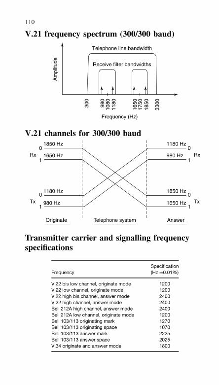
110
V.21 frequency spectrum (300/300 baud)
Am
plitu
deTelephone line bandwidth
Receive filter bandwidths
300
980
1080
1180
1650
1750
1850
3300
Frequency (Hz)
V.21 channels for 300/300 baud1850 Hz
1650 Hz
1180 Hz
980 Hz
1180 Hz
980 Hz
1850 Hz
1650 Hz
0
1Rx
0
1Tx
0
1Rx
0
1Tx
Originate AnswerTelephone system
Transmitter carrier and signalling frequencyspecifications
FrequencySpecification(Hz ±0.01%)
V.22 bis low channel, originate mode 1200V.22 low channel, originate mode 1200V.22 high bis channel, answer mode 2400V.22 high channel, answer mode 2400Bell 212A high channel, answer mode 2400Bell 212A low channel, originate mode 1200Bell 103/113 originating mark 1270Bell 103/113 originating space 1070Bell 103/113 answer mark 2225Bell 103/113 answer space 2025V.34 originate and answer mode 1800
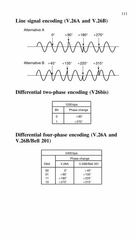
111
Line signal encoding (V.26A and V.26B)
0°
+45° +135° +225° +315°
+90° +180° +270°Alternative A
Alternative B
Differential two-phase encoding (V26bis)
1200 bps
Bit Phase change
0 +90◦
1 +270◦
Differential four-phase encoding (V.26A andV.26B/Bell 201)
2400 bps
Phase change
Dibit V.26A V.26B/Bell 201
00 0◦ +45◦
01 +90◦ +135◦
11 +180◦ +225◦
10 +270◦ +315◦
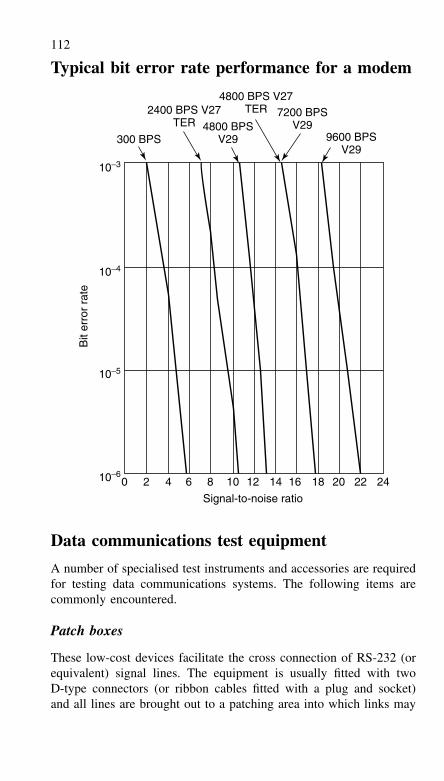
112
Typical bit error rate performance for a modem
0 2 4 6 8 10 12
Signal-to-noise ratio
Bit
erro
r ra
te
14 16 18 20 22 24
10−3
300 BPS4800 BPS
V29
2400 BPS V27TER
7200 BPSV29
9600 BPSV29
4800 BPS V27TER
10−4
10−5
10−6
Data communications test equipment
A number of specialised test instruments and accessories are requiredfor testing data communications systems. The following items arecommonly encountered.
Patch boxes
These low-cost devices facilitate the cross connection of RS-232 (orequivalent) signal lines. The equipment is usually fitted with twoD-type connectors (or ribbon cables fitted with a plug and socket)and all lines are brought out to a patching area into which links may
113
be plugged. In use, these devices are connected in series with theRS-232 serial data path and various patching combinations are testeduntil a functional interface is established. If desired, a dedicated cablemay then be manufactured in order to replace the patch box.
Gender changers
Gender changers normally comprise an extended RS-232 connectorwhich has a male connector at one end and a female connector at theother. Gender changers permit mixing of male and female connectortypes (note that the convention is male at the DTE and female atthe DCE).
Null modems
Like gender changers, these devices are connected in series with anRS-232 serial data path. Their function is simply that of changing thesignal lines so that a DTE is effectively configured as a DCE. Nullmodems can easily be set up using a patch box or manufactured inthe form of a dedicated null-modem cable.
Line monitors
Line monitors display the logical state (in terms of mark or space)present on the most commonly used data and handshaking signal lines.Light emitting diodes (LED) provide the user with a rapid indicationof which signals are present and active within the system.
Breakout boxes
Breakout boxes provide access to the signal lines and invariably com-bine the features of patch box and line monitor. In addition, switchesor jumpers are usually provided for linking lines on either side of thebox. Connection is almost invariably via two 25-way ribbon cablesterminated with connectors.
Interface testers
Interface testers are somewhat more complex than simple breakoutboxes and generally incorporate facilities for forcing lines into markor space states, detecting glitches, measuring baud rates, and alsodisplaying the format of data words. Such instruments are, not sur-prisingly, rather expensive.
114
Oscilloscopes
An oscilloscope can be used to display waveforms of signals presenton data lines. It is thus possible to detect the presence of noise andglitches as well as measuring signal voltage levels, and rise and falltimes. A compensated (×10) oscilloscope probe will normally berequired in order to minimise distortion caused by test-lead reactance.A digital storage facility can be invaluable when displaying transi-tory data.
Multimeters
A general-purpose multimeter can be useful when testing static linevoltages, cable continuity, terminating resistances, etc. A standardmulti-range digital instrument will be adequate for most applications,however, an audible continuity testing range is useful when checkingdata cables.
Fault finding on RS-232 systems
Fault finding on RS-232 systems usually involves the following basicsteps:
(a) ascertain which device is the DTE and which is the DCE. Thiscan usually be accomplished by simply looking at the connec-tors (DTE equipment is normally fitted with a male connectorwhile DCE equipment is normally fitted with a female connec-tor). Where both devices are configured as DTE (as is often thecase) a patch box or null modem should be inserted for correctoperation
(b) check that the correct cable has been used. Note that RS-232cables are provided in a variety of forms; 4-way (for dumb ter-minals), 9-way (for normal asynchronous data communications),15-way (for synchronous communications), and 25-way (for uni-versal applications). If in doubt, use a full 25-way cable
(c) check that the same data word format and baud rate has beenselected at each end of the serial link
(d) activate the link and investigate the logical state of the data (TXDand RXD) and handshaking (RTS, CTS, etc.) signal lines usinga line monitor, breakout box, or interface tester. Lines may belooped back to test each end of the link
(e) if in any doubt, refer to the equipment manufacturer’s data in orderto ascertain whether any special connections are required and to
115
ensure that the interfaces are truly compatible. Note that somemanufacturers have implemented quasi-RS-232 interfaces whichmake use of TTL signals. These are not electrically compatiblewith the normal RS-232 system
(f) the communications software should be initially configured for theleast complex protocol (eg, basic ASCII character transfer withouthandshaking). When a successful link has been established, morecomplex protocols may be attempted.
The program listing shows a simple GWBASIC program which canbe used to test an asynchronous RS-232 link in full-duplex modebetween two PCs (or PC compatibles). Similar programs can be usedin other environments or between two quite different machines. Thetwo computers should be linked using a null-modem cable (or null-modem connector) and the program should be entered, saved to disk,and then loaded and run on both computers.
The program can be easily modified to test the COM2 asyn-chronous port (rather than COM1) by changing the OPEN statementin line 150. This line may also be modified in order to test the linkat different baud rates (other than 300 baud) and with different dataformats. The OPEN command has the following syntax when usedwith a communications device:
OPEN ‘‘COMn: [speed],[parity],[data],[stop]’’ AS #filenum
Where:
n refers to the asynchronous port number (1, 2, 3, etc.)speed is the baud rate (150, 300, 600, etc.)parity is the parity selected (N = none, E = even, and O = odd)data refers to the number of data bits (5, 6, 7 or 8)stop refers to the number of stop bits (1, 1.5 or 2)
Readers are advised to consult the appropriate Microsoft GWBASICor QuickBASIC manuals for further information.
100 REM Simple full duplex communications105 REM test routine using PC COM1 serial port110 REM Data format; 300 baud, even parity115 REM seven data bits, one stop bit120 KEY OFF130 CLS140 PRINT ‘‘GWBASIC full duplex communications’’150 OPEN ‘‘COM1:300, E,7,1’’ AS #1160 K$=INKEY$
116
170 IF K$=‘‘’’THEN GOTO 210180 IF K$=CHR$(3) OR K$=CHR$(27) THEN GOTO 250190 PRINT #1,K$;200 PRINT K$;210 IF EOF(1) THEN GOTO 160220 C$=INPUT$(LOC(1),#1)230 PRINT C$;240 GOTO 160250 CLOSE #1260 CLS270 END
Cable modem
Cable modems operate over the ordinary cable-TV network and areconnected to the TV outlet at the customer end and the correspondingcable modem termination system (CMTS) at the cable-TV company’send (the Head-End). The cable modem is functionally like a local areanetwork (LAN) interface.
The cable modem is capable of a data rate typically between3 Mbps and 50 Mbps, and can transmit over a distance of 100 kmor more. The CMTS can talk to all the cable modems connected toit, but the cable modems can only talk to the CMTS and not to eachother. If two cable modems need to talk to each other, the CMTS willhave to relay the messages.
Current systems are based on standards: MCNS/DOCSIS 1.0/1.1(used in the USA) and DVB/DAVIC 1.3/1.4/1.5 (used in Europe).Cable modems from different vendors will work together, providedthat their design is based on the same standard. Version 1.0 of theMCNS standard specified 10 Mbps Ethernet as the only allowabledata-interface. By contrast, the DVB/DAVIC standard is totally openand allows any type of interface. Other types of interfaces, includingUSB, are incorporated in version 1.1 of the MCSN standard, allowingfor a wider range of cable modem configurations.
The DOCSIS standard is used in the USA, but is slightly modifiedto meet European requirements. The European version is called Euro-DOCSIS. Under DOCSIS, the frequency used to transmit data fromthe cable modem to the CMTS (up-stream) is normally in the 5 MHzto 42 MHz range for USA systems and 5 MHz to 65 MHz for Europeansystems. Data is multiplexed using TDMA (mini-slots in Europe) andmodulated on the carrier frequency using QPSK/16-QAM. Data ratesare typically 3 Mbps in the up-stream direction.
In the down-stream direction, from the CMTS to the cable modem,transmit frequencies are in the 42 MHz to 850 MHz range for USA
117
systems and 65 MHz to 850 MHz for European systems. Data is mul-tiplexed using TDM in the USA, but MPEG is used in Europe tobe compatible with digital video broadcasting (DVB). Data is mod-ulated on a carrier signal using 64/256-QAM modulation. Data ratesare typically 27 to 56 Mbps in the down-stream direction.
Most cable-TV networks are hybrid fibre-coax (HFC). The signalsare transmitted over fibre-optic cables from the CMTS to a locationnear the subscriber. At that point, the signal is converted to electricalfor transmission over coaxial cables that enter the subscriber premises.
One CMTS will normally drive up to 2000 simultaneous cablemodem users on a single TV channel. If more cable modems arerequired, the number of TV channels has to be increased.
The cable modem can be internal or external. The external cablemodem can connect to a number of computers using an ordinary Eth-ernet connection. Another interface found on external cable modemsis the Universal Serial Bus (USB), but this only allows one PC tobe connected at any one time. The internal cable modem is usuallya PCI bus add-in card that goes inside the PC. This type of cablemodem can only be used in desktop PC’s and thus may not havegalvanic isolation from the mains supply. In some countries, and onsome cable-TV networks, it may not be possible to use internal cablemodems for technical or regulatory reasons.
The interactive set-top box is also a cable modem and is used inconjunction with a TV set. Its primary function is to provide more TVchannels using a limited number of carrier frequencies. This is possi-ble with the use of digital television encoding (DVB). An interactiveset-top box provides a return channel, usually a separate telephoneline, which gives the user access to the Internet and email using theTV screen as a display.
Data Communications EquipmentATM media converters
ATM media converters provide a means of interconnecting ATM sig-nals between a variety of different media including shielded twistedpairs, unshielded twisted pairs, coaxial cables, single mode opticalfibres and multimode optical fibres. A single ATM media convertercan be used to connect two ATM devices operating with dissimilarphysical and electrical interfaces. A pair of ATM media convertersmay be used to connect two devices having the same interface butoperating over a data transmission path based on a different physicalmedium.
118
ATM rate and media converters
ATM rate and media converters provide asynchronous transfer moderate conversion between two devices by extracting ATM cells fromone interface before sending them over a different interface. A largeFIFO (first-in first-out) buffer is used for rate adaptation and the ATMflow control loop is adjusted in accordance with the available bitrate (ABR) in order to avoid cell losses and FIFO overflow. Variousinterface standards and physical media are usually supported. Thesemay include E1 over coaxial cable and unshielded twisted pair, DS1over unshielded twisted pair, E3 over coaxial cable, DS3 over coaxialcable, etc.
Baluns
Baluns provide a means of connecting an unbalanced line (eg, coaxialcable) to a balanced line (eg, four-wire twisted pair). Such devicesare invariably passive (ie, they require no power).
Baseband modems
Baseband modems (also known as shorthaul modems) enable devicessuch as terminals, computers, controllers, etc. to be interconnectedover relatively short distances such as inside buildings, within a siteboundary (eg, a college campus), or across a small town. With sucha device, a typical range of up to about 10 km can be achieved at adata rate of 9.6 kbps using a conventional two-wire telephone line.
Bridges
A bridge is a device that interconnects two or more networks ofthe same type (eg, two networks based on the Ethernet standard ortwo Token Ring IEEE 802.5 LANs). Bridges operate within the DataLink Layer of the ISO model for OSI. Adaptive bridges are able toconfigure themselves by constructing a table of user addresses. Remotebridges provide a means of interconnecting two networks in differentlocations (eg, a central office network with a remote office network).In this case, each network is fitted with a bridge and these are thenlinked together with a digital circuit (eg, an E1 line).
Coaxial multiplexers
Coaxial multiplexers enable two (or more) coaxial cables to be con-nected to an incoming or outgoing coaxial cable. The same impedanceis presented at each port and no power is required by the device.
119
Current loop converters
Current loop converters convert standard RS-232/V.24 signals intobi-directional current loop signals (either 20 or 60 mA). Data rates ofup to 19.2 kbps and distances of up to 5 or 6 km can be supportedby such a device. Active current loop converters provide a source ofloop current while passive current loop converters accept the currentsupplied from another current loop device.
Digital service access devices
Digital service access devices provide the digital interface for thecustomer premises equipment (CPE) to the carrier’s digital services.Digital services access devices extend the network to the customer’spremises and, in this respect, they differ from conventional digitalmodems.
Fibre optic modems
Standard fibre optic modems are designed to operate with opticalfibres rather than copper cables. Data rates of 128, 256, 384, 512,768, 1024, 1544 (T1) and 2048 kbps (E1) can be achieved with suchdevices. Typical distances are up to 5 km (850 nm multimode fibre),20 km (1300 nm single mode fibre) and 50 km (laser diode). Thedigital interface usually supports one or more of the following stan-dards; V.24, V.35, X.21, RS-520 and G.703. High-speed fibre opticmodems support the use of data rates of 34.368 (E3), 44.736 (T3) and51.84 Mbps (STS-1).
Data rates of 10 Gbps are transmitted over fibre networks, usingWDM and externally modulated lasers. The terminal equipment israck mounted and cannot really be described as a ‘modem’.
Frame relays (packet assemblers/disassemblers)
Frame relays can be used to connect a number of asynchronous datachannels to an X.25 or frame relay network. Such devices can alsoserve as access units to an X.25 private or public network or as accessservers to a mainframe with an X.25 port.
Gateways
Gateways perform the functions of both routing and media conver-sion (eg, converting circuit-oriented or analogue information, such as
120
voice into TCP/IP packets, and vice versa). One example of their useis in local telephone exchanges, to provide access to the Internet. Inthis situation, the gateway off-loads IP traffic from the PSTN as soonas possible. Moving IP traffic off the PSTN frees up the capacity ofswitches and trunks to allow them to handle circuit-switched calls.New sessions to ISPs are established by linking the dialled numberwith an IP address, so that one gateway can support circuit-switchedaccess to multiple ISPs, thereby controlling ISP and network opera-tor cost.
Hubs
Hubs help to simplify the wiring of a LAN by providing a commonphysical point for cabling. Hubs do not affect the way in which a net-work operates – once inside the hub, the original bus or ring topologyis preserved. A typical Ethernet hub provides sixteen 10Base T portswithin one physical unit. Two further ports are available for expansionby ‘stacking’.
Interface converters
Interface converters provide a means of linking two dissimilar net-works including coping with different physical connections, signalcharacteristics, and different meanings of exchanged signals. Inter-face converters are often required to also cope with a change of datarate in which case they are more properly known as ‘rate and interfaceconverters’.
Inverse multiplexers
Inverse multiplexing is used for the transmission of a high-speed datachannel over two or more lower speed WAN links. As an example,an aggregate data rate of up to 384 kbps (V.35) can be realised usingup to six multiplexed leased lines at 64 kbps. Inverse multiplexersmust be present at both sites – the remote multiplexer reconstructsthe high-speed data signal from the signals present on each of thelower speed links. Inverse multiplexers can also be used to back uphigh-speed leased/digital lines using one or more ISDN links whichcan be brought into service during times of peak traffic demand.
LAN managers
LAN managers comprise software and hardware (usually based on aPC platform) which will provide direct on-line supervision of network
121
configuration, diagnostics, monitoring and control. Most currentlyavailable LAN management software runs under Microsoft Windows,NT or Windows 95. In order to determine network loading and iden-tify problem areas, real-time statistical information can be provideddisplayed in various formats, including line graph, bar chart or tabularform. More sophisticated LAN managers feature automatic recogni-tion of access units, enhanced diagnostic and security features, andan ability to control third party equipment.
Line termination units
Line termination units provide signal conditioning (equalisation andadaptive filtering) to combat the effects of attenuation, distortion andnoise present in lines. At distances of up to about 5 km with con-ventional four-wire copper cables, they can both eliminate the needfor repeaters and provide an effective alternative to the use of fibreoptical cables. In some cases, an embedded channel may be providedfor control and diagnostics.
Medium range (‘voice band’) modems
Standard modems operating with data rates of up to 19.2 kbps canbe used with conditioned lines at distances of up to 100 km (dis-tances of up to about 60 km can be achieved when conditioned linesare not available). Such modems operate in a similar manner to con-ventional telephone-line modems but cater for both synchronous andasynchronous operation and generally incorporate diagnostics to V.54with built-in bit error rate testers.
Multiplexers
Multiplexers provide an efficient and cost-effective method of inte-grating data, voice, fax and LAN traffic over digital data services,leased lines, and ISDN. Modular multiplexer design allows servicessuch as V.35, RS-530, V.24/RS-232 and X.21 to share the same leasedline or private channel at data rates typically in the range 9.6 to768 kbps.
Packet switching access units
Packet switching access units provide encapsulation of protocols overa Frame Relay or an X.25 network. Various protocols can usually beaccommodated including X.25, Frame Relay, STEM and HDLC.
122
Rate converters
A typical application for a rate converter is that of facilitating theconnection of a 56 or 48 kbps terminal to a 64 or 56 kbps line. Afacility for a synchronous sub-channel at 4.8 or 9.6 kbps may also beprovided.
Rate and interface converters
Combined rate and interface converters are also available to cope withsituations in which the physical interconnections, signal interpretationand data rates may differ on both sides of the interface. A typicalapplication for such a device would be that of converting an E1 frame(2.048 Mbps) into two T1 frames (1.024 Mbps) – hence allowing E1equipment to operate with only T1 facilities.
Repeaters
Repeaters amplify and regularise the voltage and/or current levels of adigital signal. This enables them to compensate both for losses in theline and distortion due to non-linearity of the line’s frequency responsecharacteristic. The content of the digital signal (in terms of the datapresent and its rate) remain unchanged by a repeater. Repeaters canbe line-powered (using either through or loop modes) or may derivetheir power supply from a battery or standard a.c. mains supply outlet.In many cases, local loopback support may be available so that therepeater – as well as the line up to that point in the circuit – can betested. A typical E1 repeater (2.048 Mbps) will provide satisfactoryoperation with up to 2 km of conventional cable and line attenuationof up to 40 dB. Beyond that distance, repeaters can be chained toachieve greater distances.
Routers
Routers, like bridges, can be used to interconnect LANs. Unlikebridges, routers operate at the Network Layer of the ISO model forOSI as well as the Data Link Layer. This permits the use of higherlevel addresses. Each router has its own network address and onlyneeds the address of another router in order to reach all of the usersconnected to the network served by that router.
Switches
Ethernet switches increase network performance by not passing anyunnecessary traffic onto individual network segments attached to the
123
switch. They also filter packets a bit like a router does. When a packetarrives, the header is checked to determine which segment the packetis destined for, and then the switch forwards the packet to that seg-ment. This prevents the packet being forwarded onto unnecessarysegments, thus reducing the traffic. To reduce the switch workload,nodes that inter-communicate frequently should be placed on the samesegment. Switches work at the MAC layer level.
Cut-through switches
Cut-through switches use either a cross-bar or cell back-plane archi-tecture. Only the first few bytes of the packet are read to obtain thesource and destination addresses. The packets are then passed throughto the destination segment without checking the rest of the packet forerrors. The lack of checking means that invalid packets can still bepassed onto other segments, but ensures that there is little throughputdelay.
Cross-bar switches read the destination address then immediatelyforward the packet. Although it acts as a simple repeater once thepath is established, it can introduce delay if the destination port isbusy because it may need to buffer the packet.
Cell back-plane switches break the frame into small fixed celllengths. Each cell is labelled with special headers that contain theaddress(s) of the destination port. The cells are buffered at the desti-nation port and then re-assembled into a packet. The packet is thentransmitted onward. The data rate on the back-plane is significantlygreater than the aggregate data rate of the ports. In overloaded net-works, cell back-plane switching gives a better performance thancross-bar switching
Store and forward switches
Store and forward switches examine the entire packet. Each packet isbuffered at the switch input and then examined. The switch removesany bad packets that it detects and good packets are forwarded to thecorrect segment. Store and forward switches detect more errors thancut-through switches, although they do impose a small throughputdelay.
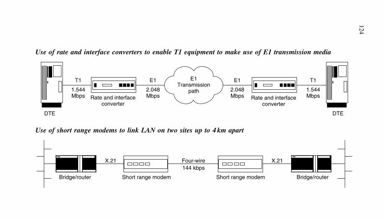
124
Use of rate and interface converters to enable T1 equipment to make use of E1 transmission media
T1 E1
1.544Mbps
T1
1.544Mbps
2.048MbpsRate and interface
converter
E1
2.048Mbps Rate and interface
converter
E1Transmission
path
DTE DTE
Use of short range modems to link LAN on two sites up to 4 km apart
X.21 X.21Four-wire144 kbps
Short range modem Short range modemBridge/router Bridge/router
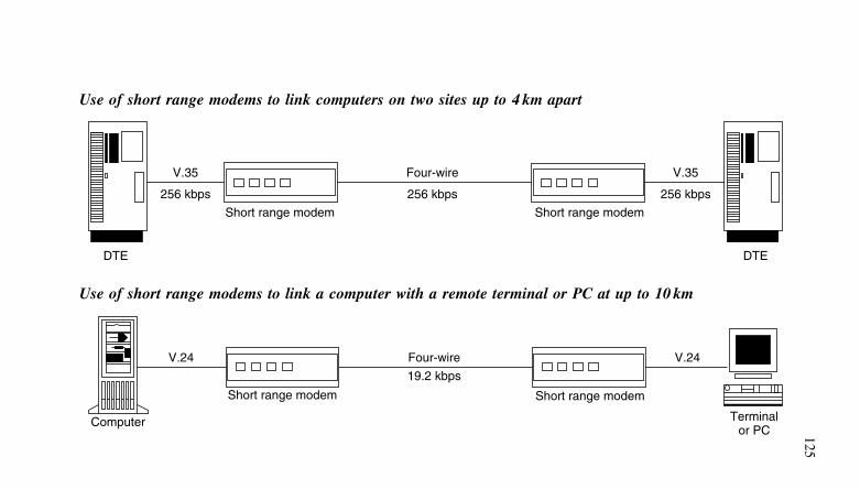
125
Use of short range modems to link computers on two sites up to 4 km apart
V.35
256 kbps
V.35
256 kbps
Four-wire
256 kbps
DTE DTE
Short range modem Short range modem
Use of short range modems to link a computer with a remote terminal or PC at up to 10 km
V.24 V.24
Terminalor PC
Four-wire
19.2 kbps
Computer
Short range modem Short range modem
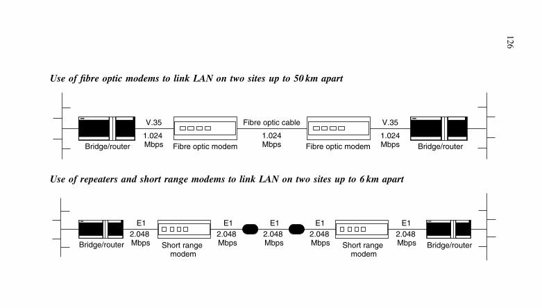
126
Use of fibre optic modems to link LAN on two sites up to 50 km apart
V.35
1.024 Mbps
Fibre optic cable
1.024Mbps
V.35
1.024MbpsBridge/router Bridge/routerFibre optic modem Fibre optic modem
Use of repeaters and short range modems to link LAN on two sites up to 6 km apart
E12.048 Mbps
E12.048 Mbps
E12.048 Mbps
E12.048 Mbps
E12.048 MbpsBridge/router Short range
modemShort range
modemBridge/router
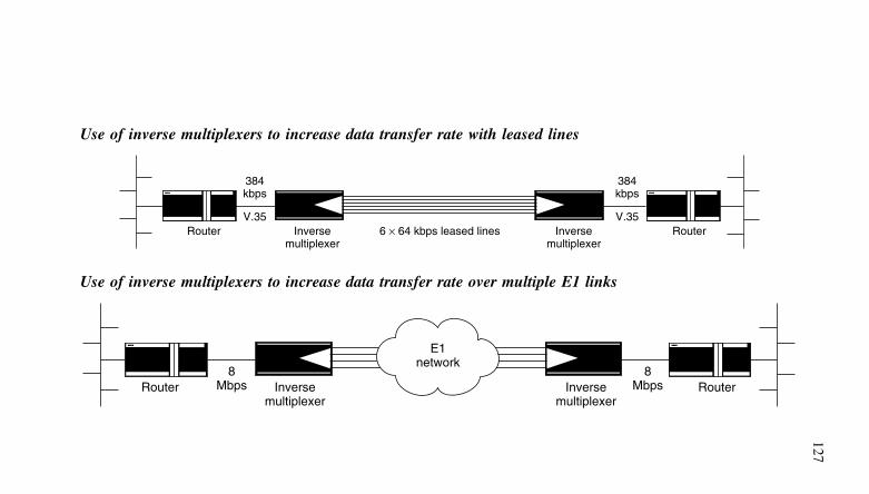
127
Use of inverse multiplexers to increase data transfer rate with leased lines
Router Router6 × 64 kbps leased linesInversemultiplexer
Inversemultiplexer
384kbps
V.35
384kbps
V.35
Use of inverse multiplexers to increase data transfer rate over multiple E1 links
Router RouterInversemultiplexer
E1network
Inversemultiplexer
8Mbps
8Mbps
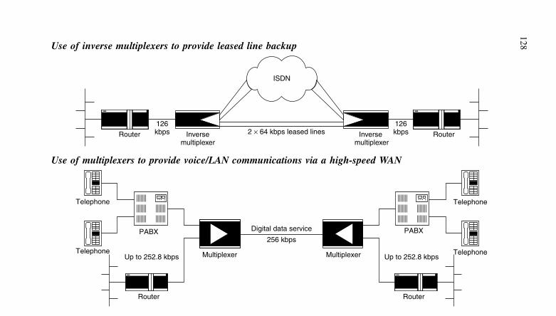
128Use of inverse multiplexers to provide leased line backup
Router Router
126kbps
126kbps
ISDN
2 × 64 kbps leased lines Inverse multiplexer
Inversemultiplexer
Use of multiplexers to provide voice/LAN communications via a high-speed WAN
Telephone
Telephone
Multiplexer Multiplexer
Router
PABX
Up to 252.8 kbps
256 kbps
Digital data service
Telephone
Telephone
Router
PABX
Up to 252.8 kbps
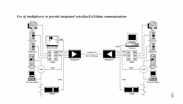
129
Use of multiplexers to provide integrated voice/fax/LAN/data communications
Multiplexer
Telephone
Fax
Router
PABX
Data
Data
Telephone
Server
Microcomputer
LAN
Fax
Voice
Data
PC work station
Fax
Multiplexer
Telephone
Router
PABX
Data
Data
Telephone
Server
Terminal
LAN
Fax
Voice
Data
PC work station
Leased line
9.6 to 796 kbps
6 Parallel interfaces
The advantage of a parallel interface is the speed at which data can betransferred from a computer to a peripheral device. Usually, parallelinterfaces have eight data-carrying connections, so the data can betransferred at least eight times faster than an equivalent serial con-nection. An alternative way of looking at this is that the data rate oneach data line to a peripheral can be eight or more times slower inorder to carry the same amount of data in a given period.
The most basic parallel connection a computer bus, these can be8, 16 or 32 bits wide. A microprocessor can read from or write to thisbus. Integrated circuits acts as buffers so that external data is onlyallowed onto the bus when the microprocessor is in its read mode.The buffer is arranged to output data when the microprocessor is inits write mode.
There are two common parallel interfaces used external to thecomputer: the Centronics printer port and the IEEE-488 bus. Theseare described later in this chapter.
Parallel I/O devicesParallel I/O devices allow a byte of data to be transferred at a timebetween computer systems and external devices. Parallel I/O is rela-tively easy to implement since it only requires an arrangement basedon 8-bit buffers or latches. The software and hardware requirementsof this form of I/O are thus minimal.
Parallel I/O devices enjoy a variety of names depending upontheir manufacturer. Despite this, parallel I/O devices are remarkablysimilar in internal architecture and operation with only a few minordifferences distinguishing one device from the next.
Programmable parallel I/O devices can normally be configured(under software control) in one of several modes:
(a) all eight lines configured as inputs(b) all eight lines configured as outputs(c) lines individually configured as inputs or outputs.
In addition, extra lines to I/O lines are normally available to facil-itate handshaking. This provides a means of controlling the exchangeof data between a computer system and external hardware. The nomen-clature used for parallel I/O lines and their function tends to vary fromchip to chip. The following applies to the majority of devices:
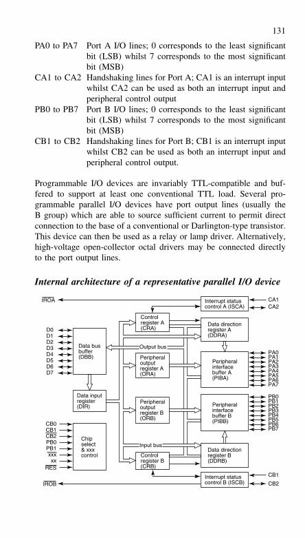
131
PA0 to PA7 Port A I/O lines; 0 corresponds to the least significantbit (LSB) whilst 7 corresponds to the most significantbit (MSB)
CA1 to CA2 Handshaking lines for Port A; CA1 is an interrupt inputwhilst CA2 can be used as both an interrupt input andperipheral control output
PB0 to PB7 Port B I/O lines; 0 corresponds to the least significantbit (LSB) whilst 7 corresponds to the most significantbit (MSB)
CB1 to CB2 Handshaking lines for Port B; CB1 is an interrupt inputwhilst CB2 can be used as both an interrupt input andperipheral control output.
Programmable I/O devices are invariably TTL-compatible and buf-fered to support at least one conventional TTL load. Several pro-grammable parallel I/O devices have port output lines (usually theB group) which are able to source sufficient current to permit directconnection to the base of a conventional or Darlington-type transistor.This device can then be used as a relay or lamp driver. Alternatively,high-voltage open-collector octal drivers may be connected directlyto the port output lines.
Internal architecture of a representative parallel I/O device
D0D1D2D3D4D5D6D7
Data busbuffer(DBB)
Output bus
Controlregister A(CRA)
Controlregister B(CRB)
Peripheraloutputregister A(ORA)
Chipselect& xxxcontrol
Data inputregister(DIR)
CB0CB1CB2PB0PB1xxxxx
RES
Peripheraloutputregister B(ORB)
Input bus
IROA
IROB
PA0
CA1CA2
CB1
CB2
PA1PA2PA3PA4
PA6PA5
PA7
PB0PB1PB2PB3PB4
PB6PB5
PB7
Interrupt statuscontrol A (ISCA)
Interrupt statuscontrol B (ISCB)
Data directionregister A(DDRA)
Data directionregister B(DDRB)
Peripheralinterfacebuffer B(PIBB)
Peripheralinterfacebuffer A(PIBA)
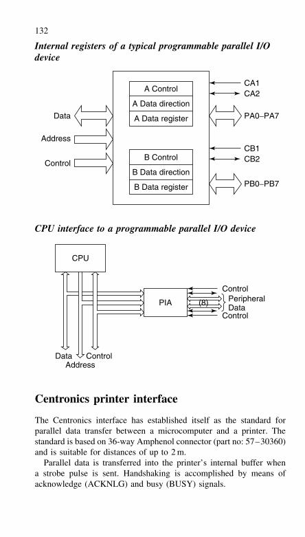
132
Internal registers of a typical programmable parallel I/Odevice
Address
Data PA0−PA7
PB0−PB7
CB2CB1
ControlB Control
B Data direction
B Data register
A Data direction
A Data register
A ControlCA2CA1
CPU interface to a programmable parallel I/O device
CPU
PIA
Data ControlAddress
ControlPeripheralData
Control
(8)
Centronics printer interface
The Centronics interface has established itself as the standard forparallel data transfer between a microcomputer and a printer. Thestandard is based on 36-way Amphenol connector (part no: 57–30360)and is suitable for distances of up to 2 m.
Parallel data is transferred into the printer’s internal buffer whena strobe pulse is sent. Handshaking is accomplished by means ofacknowledge (ACKNLG) and busy (BUSY) signals.
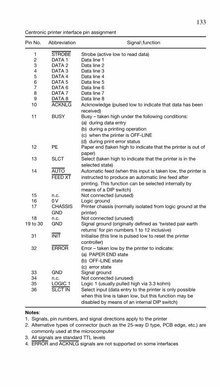
133
Centronic printer interface pin assignment
Pin No. Abbreviation Signal\function
1 STROBE Strobe (active low to read data)2 DATA 1 Data line 13 DATA 2 Data line 24 DATA 3 Data line 35 DATA 4 Data line 46 DATA 5 Data line 57 DATA 6 Data line 68 DATA 7 Data line 79 DATA 8 Data line 8
10 ACKNLG Acknowledge (pulsed low to indicate that data has beenreceived)
11 BUSY Busy – taken high under the following conditions:(a) during data entry(b) during a printing operation(c) when the printer is OFF-LINE(d) during print error status
12 PE Paper end (taken high to indicate that the printer is out ofpaper)
13 SLCT Select (taken high to indicate that the printer is in theselected state)
14 AUTOFEED XT
Automatic feed (when this input is taken low, the printer isinstructed to produce an automatic line feed afterprinting. This function can be selected internally bymeans of a DIP switch)
15 n.c. Not connected (unused)16 0 V Logic ground17 CHASSIS
GNDPrinter chassis (normally isolated from logic ground at theprinter)
18 n.c. Not connected (unused)19 to 30 GND Signal ground (originally defined as ‘twisted pair earth
returns’ for pin numbers 1 to 12 inclusive)31 INIT Initialise (this line is pulsed low to reset the printer
controller)32 ERROR Error – taken low by the printer to indicate:
(a) PAPER END state(b) OFF-LINE state(c) error state
33 GND Signal ground34 n.c. Not connected (unused)35 LOGIC 1 Logic 1 (usually pulled high via 3.3 kohm)36 SLCT IN Select input (data entry to the printer is only possible
when this line is taken low, but this function may bedisabled by means of an internal DIP switch)
Notes:1. Signals, pin numbers, and signal directions apply to the printer2. Alternative types of connector (such as the 25-way D type, PCB edge, etc.) are
commonly used at the microcomputer3. All signals are standard TTL levels4. ERROR and ACKNLG signals are not supported on some interfaces
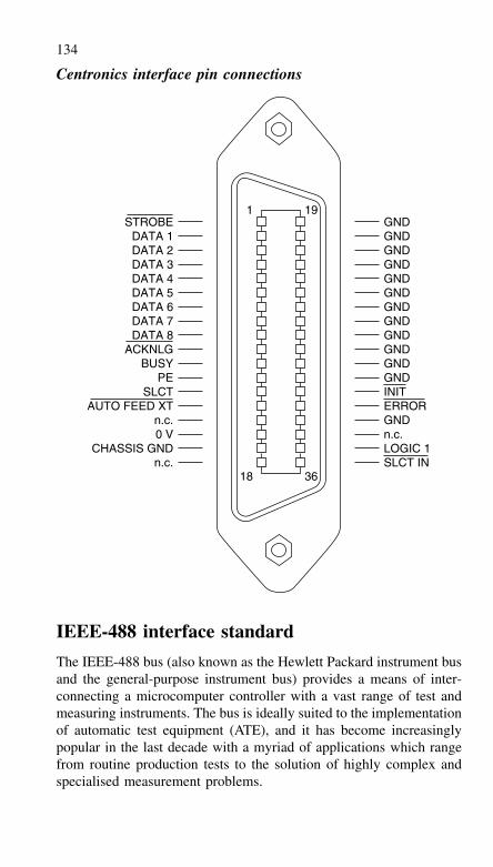
134
Centronics interface pin connections
SLCT IN18 36
1 19GNDGNDGNDGNDGNDGNDGNDGNDGNDGNDGNDGNDINITERRORGNDn.c.LOGIC 1
STROBEDATA 1DATA 2DATA 3DATA 4DATA 5DATA 6DATA 7DATA 8
ACKNLGBUSY
PESLCT
AUTO FEED XTn.c.0 V
CHASSIS GNDn.c.
IEEE-488 interface standard
The IEEE-488 bus (also known as the Hewlett Packard instrument busand the general-purpose instrument bus) provides a means of inter-connecting a microcomputer controller with a vast range of test andmeasuring instruments. The bus is ideally suited to the implementationof automatic test equipment (ATE), and it has become increasinglypopular in the last decade with a myriad of applications which rangefrom routine production tests to the solution of highly complex andspecialised measurement problems.
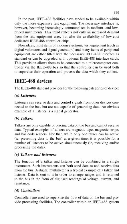
135
In the past, IEEE-488 facilities have tended to be available withinonly the more expensive test equipment. The necessary interface is,however, becoming increasingly commonplace in medium- and low-priced instruments. This trend reflects not only an increased demandfrom the test equipment user, but also the availability of low-costdedicated IEEE-488 controller chips.
Nowadays, most items of modern electronic test equipment (such asdigital voltmeters and signal generators) and many items of peripheralequipment are either fitted with the necessary IEEE-488 interface asstandard or can be upgraded with optional IEEE-488 interface cards.This provision allows them to be connected to a microcomputer con-troller via the IEEE-488 bus so that the controller can be used bothto supervise their operation and process the data which they collect.
IEEE-488 devicesThe IEEE-488 standard provides for the following categories of device:
(a) Listeners
Listeners can receive data and control signals from other devices con-nected to the bus, but are not capable of generating data. An obviousexample of a listener is a signal generator.
(b) Talkers
Talkers are only capable of placing data on the bus and cannot receivedata. Typical examples of talkers are magnetic tape, magnetic stripe,and bar code readers. Not that, while only one talker can be active(ie, presenting data to the bus) at a given time, it is possible for anumber of listeners to be active simultaneously (ie, receiving and/orprocessing the data).
(c) Talkers and listeners
The function of a talker and listener can be combined in a singleinstrument. Such instruments can both send data to and receive datafrom the bus. A digital multimeter is a typical example of a talker andlistener. Data is sent to it in order to change ranges and is returnedto the bus in the form of digitised readings of voltage, current, andresistance.
(d) Controllers
Controllers are used to supervise the flow of data on the bus and pro-vide processing facilities. The controller within an IEEE-488 system
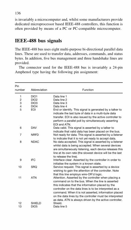
136
is invariably a microcomputer and, whilst some manufacturers providededicated microprocessor based IEEE-488 controllers, this function isoften provided by means of a PC or PC-compatible microcomputer.
IEEE-488 bus signals
The IEEE-488 bus uses eight multi-purpose bi-directional parallel datalines. These are used to transfer data, addresses, commands, and statusbytes. In addition, five bus management and three handshake lines areprovided.
The connector used for the IEEE-488 bus is invariably a 24-pinAmphenol type having the following pin assignment:
Pinnumber Abbreviation Function
1 DIO1 Data line 12 DIO2 Data line 23 DIO3 Data line 34 DIO4 Data line 45 EOI End or identify. This signal is generated by a talker to
indicate the last byte of data in a multi-byte datatransfer. EOI is also issued by the active controller toperform a parallel poll by simultaneously assertingEOI and ATN.
6 DAV Data valid. This signal is asserted by a talker toindicate that valid data has been placed on the bus.
7 NRFD Not ready for data. This signal is asserted by a listenerto indicate that it is not yet ready to accept data.
8 NDAC No data accepted. This signal is asserted by a listenerwhilst data is being accepted. When several devicesare simultaneously listening, each device releases thisline at its own rate (the slowest device will be the lastto release the line).
9 IFC Interface clear. Asserted by the controller in order toinitialise the system in a known state.
10 SRQ Service request. This signal is asserted by a devicewishing to gain the attention of the controller. Notethat this line employs wire-OR’d logic.
11 ATN Attention. Asserted by the controller when placing acommand on to the bus. When the line is assertedthis indicates that the information placed by thecontroller on the data lines is to be interpreted as acommand. When it is not asserted, information placedon the data lines by the controller must be interpretedas data. ATN is always driven by the active controller.
12 SHIELD Shield.13 DIO5 Data line 5
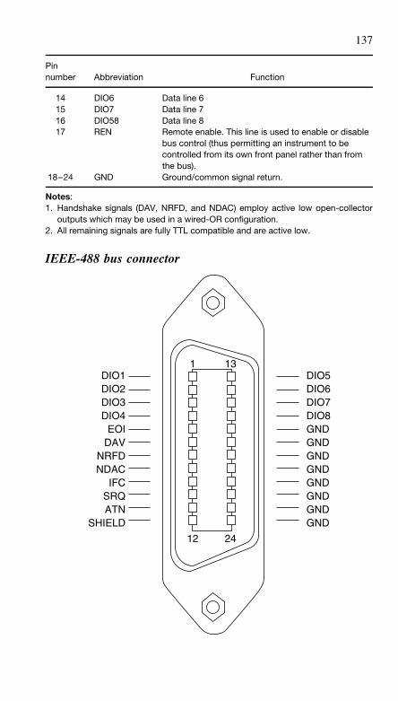
137
Pinnumber Abbreviation Function
14 DIO6 Data line 615 DIO7 Data line 716 DIO58 Data line 817 REN Remote enable. This line is used to enable or disable
bus control (thus permitting an instrument to becontrolled from its own front panel rather than fromthe bus).
18–24 GND Ground/common signal return.
Notes:1. Handshake signals (DAV, NRFD, and NDAC) employ active low open-collector
outputs which may be used in a wired-OR configuration.2. All remaining signals are fully TTL compatible and are active low.
IEEE-488 bus connector
DIO1DIO2DIO3DIO4
EOIDAV
NRFDNDAC
IFCSRQATN
SHIELD
DIO5DIO6DIO7DIO8GNDGNDGNDGNDGNDGNDGNDGND
1 13
12 24
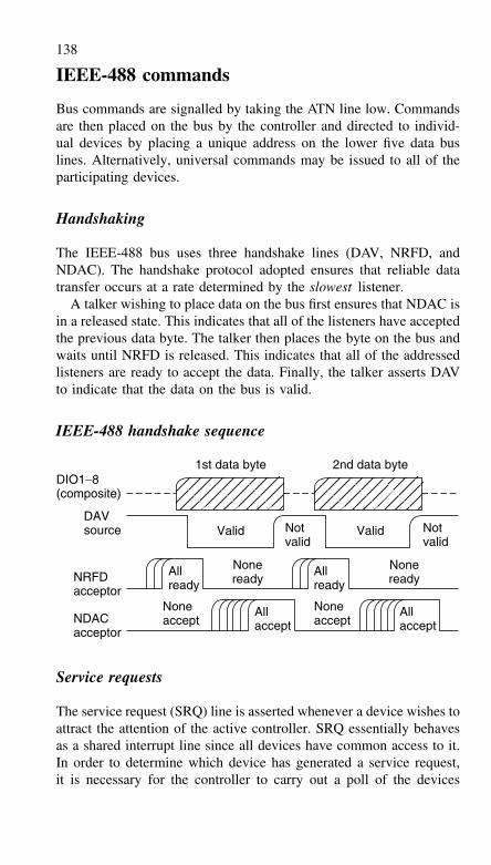
138
IEEE-488 commands
Bus commands are signalled by taking the ATN line low. Commandsare then placed on the bus by the controller and directed to individ-ual devices by placing a unique address on the lower five data buslines. Alternatively, universal commands may be issued to all of theparticipating devices.
Handshaking
The IEEE-488 bus uses three handshake lines (DAV, NRFD, andNDAC). The handshake protocol adopted ensures that reliable datatransfer occurs at a rate determined by the slowest listener.
A talker wishing to place data on the bus first ensures that NDAC isin a released state. This indicates that all of the listeners have acceptedthe previous data byte. The talker then places the byte on the bus andwaits until NRFD is released. This indicates that all of the addressedlisteners are ready to accept the data. Finally, the talker asserts DAVto indicate that the data on the bus is valid.
IEEE-488 handshake sequence
DIO1−8(composite)
DAVsource
NRFDacceptor
NDACacceptor
1st data byte 2nd data byte
Valid Notvalid
Allready
Noneaccept
Noneaccept
Allaccept
Allaccept
Allready
Noneready
Noneready
Notvalid
Valid
Service requests
The service request (SRQ) line is asserted whenever a device wishes toattract the attention of the active controller. SRQ essentially behavesas a shared interrupt line since all devices have common access to it.In order to determine which device has generated a service request,it is necessary for the controller to carry out a poll of the devices
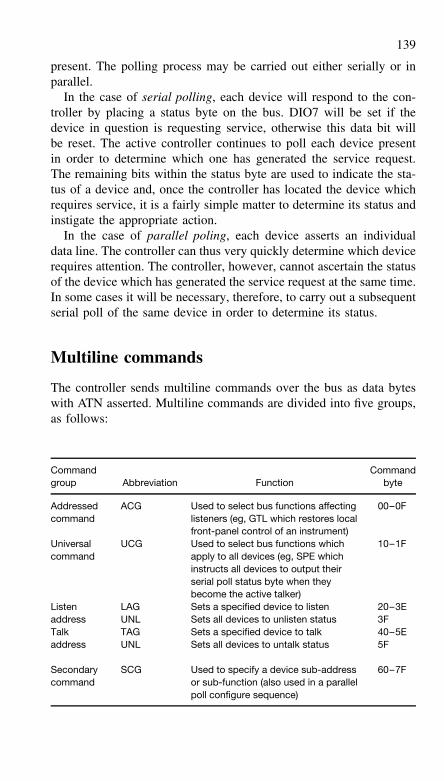
139
present. The polling process may be carried out either serially or inparallel.
In the case of serial polling, each device will respond to the con-troller by placing a status byte on the bus. DIO7 will be set if thedevice in question is requesting service, otherwise this data bit willbe reset. The active controller continues to poll each device presentin order to determine which one has generated the service request.The remaining bits within the status byte are used to indicate the sta-tus of a device and, once the controller has located the device whichrequires service, it is a fairly simple matter to determine its status andinstigate the appropriate action.
In the case of parallel poling, each device asserts an individualdata line. The controller can thus very quickly determine which devicerequires attention. The controller, however, cannot ascertain the statusof the device which has generated the service request at the same time.In some cases it will be necessary, therefore, to carry out a subsequentserial poll of the same device in order to determine its status.
Multiline commands
The controller sends multiline commands over the bus as data byteswith ATN asserted. Multiline commands are divided into five groups,as follows:
Commandgroup Abbreviation Function
Commandbyte
Addressedcommand
ACG Used to select bus functions affectinglisteners (eg, GTL which restores localfront-panel control of an instrument)
00–0F
Universalcommand
UCG Used to select bus functions whichapply to all devices (eg, SPE whichinstructs all devices to output theirserial poll status byte when theybecome the active talker)
10–1F
Listenaddress
LAGUNL
Sets a specified device to listenSets all devices to unlisten status
20–3E3F
Talkaddress
TAGUNL
Sets a specified device to talkSets all devices to untalk status
40–5E5F
Secondarycommand
SCG Used to specify a device sub-addressor sub-function (also used in a parallelpoll configure sequence)
60–7F
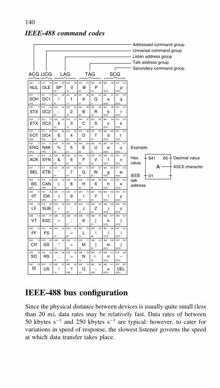
140
IEEE-488 command codes
NUL500 0 510 16 520
00
01
02 0218 18 SCG SCG
03 0319 19 SCG SCG
04DCLSDC 0420 20 SCG SCG
05PPUPPC 0521 21 SCG SCG
08SPEGET 0824 24 SCG SCG
09SPDTT 0925 25 SCG SCG
10 1026 26 SCG SCG
11 1127 27 SCG SCG
12 1228 28 SCG SCG
13 1329 29 SCG SCG
14 1430 30 SCG SCG
15 15UNL UNT SCG SCG
06 0622 22 SCG SCG
07 0723 23 SCG SCG
0117 17 SCG SCGOTL LLO
32 530
16 16 SCG SCG
48 540
00
64 550 80 560 96 570 112
501 1 511 17 521 33 531 49 541 65 551 81 561 97 571 113
502 2 512 18 522 34 532 50 542 66 552 82 562 98 572 114
503 3 513 19 523 35 533 51 543 67 553 83 563 99 573 115
504 4 514 20 524 36 534 52 544 68 554 84 564 100 574 116
505 5 515 21 525 37 535 53 545 69 555 85 565 101 575 117
506 6 516 22 526 38 536 54 546 70 556 86 566 102 576 118
507 7 517 23 527 39 537 55 547 71 557 87 567 103 577 119
508 8 518 24 528 40 538 56 548 72 558 88 568 104 578 120
509 9 519 25 529 41 539 57 549 73 559 89 569 105 579 121
50A 10 51A 26 52A 42 53A 58 54A 74 55A 90 56A 106 57A 122
50B 11 51B 27 52B 43 53B 59 54B 75 55B 91 56B 107 57B 123
50C 12 51C 28 52C 44 53C 60 54C 76 55C 92 56C 108 57C 124
50D 13 51D 29 52D 45 53D 61 54D 77 55D 93 56D 109 57D 125
50E 14 51E 30 52E 46 53E 62 54E 78 55E 94 56E 110 57E 126
50F 15 51F 31 52F 47 53F 63 54F 79 55F 95 56F 111 57F 127
DLE SP 0 @ P p
SOH DC1 ! 1 A Q a q
STX DC2 - 2 B R b r
ETX DC3 # 3 C S c s
EOT DC4 $ 4 D T d t
ENQ NAK % 5 E U e u Example:
Hex.value
Decimal value
ASCII character
IEEEtalkaddress
ACK SYN & 6 F V f v
BEL ETB ' 7 G W g w
BS CAN ( 8 H X h x
IIT EM ) 9 I Y i y
LF SUB ∗ : J Z j z
VT ESC + ; K [ k {
FF FS . < L \ l |
CR GS " = M ]
−
m }
SO RS , > N > n −
SI US / ? O o DEL
$41 65
01
A
Addressed command groupUniversal command groupListen address groupTalk address groupSecondary command group
ACG UCG LAG TAG SCG
IEEE-488 bus configuration
Since the physical distance between devices is usually quite small (lessthan 20 m), data rates may be relatively fast. Data rates of between50 kbytes s−1 and 250 kbytes s−1 are typical: however, to cater forvariations in speed of response, the slowest listener governs the speedat which data transfer takes place.
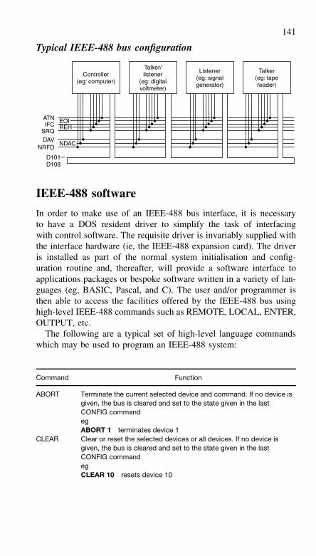
141
Typical IEEE-488 bus configuration
ATNIFC
SRQDAV
NRFD
D101−D108
EOIREH
NDAC
Controller(eg: computer)
Talker(eg: tapereader)
Listener(eg: signalgenerator)
Talker/listener
(eg: digitalvoltmeter)
IEEE-488 software
In order to make use of an IEEE-488 bus interface, it is necessaryto have a DOS resident driver to simplify the task of interfacingwith control software. The requisite driver is invariably supplied withthe interface hardware (ie, the IEEE-488 expansion card). The driveris installed as part of the normal system initialisation and config-uration routine and, thereafter, will provide a software interface toapplications packages or bespoke software written in a variety of lan-guages (eg, BASIC, Pascal, and C). The user and/or programmer isthen able to access the facilities offered by the IEEE-488 bus usinghigh-level IEEE-488 commands such as REMOTE, LOCAL, ENTER,OUTPUT, etc.
The following are a typical set of high-level language commandswhich may be used to program an IEEE-488 system:
Command Function
ABORT Terminate the current selected device and command. If no device isgiven, the bus is cleared and set to the state given in the lastCONFIG commandegABORT 1 terminates device 1
CLEAR Clear or reset the selected devices or all devices. If no device isgiven, the bus is cleared and set to the state given in the lastCONFIG commandegCLEAR 10 resets device 10
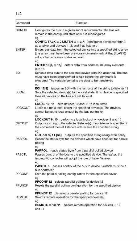
142
Command Function
CONFIG Configures the bus to a given set of requirements. The bus willremain in the configured state until it is reconfiguredegCONFIG TALK = 2 LISTEN = 1, 3, 4 configures device number 2as a talker and devices 1, 3, and 4 as listeners
ENTER Enters bus data from the selected device into a specified string array(the array must have been previously dimensioned). A flag (FLAG%)will contain any error codes returnedegENTER 10[$, 0, 15] enters data from address 10, array elements0 to 18
EOI Sends a data byte to the selected device with EOI asserted. The busmust have been programmed to talk before the command isexecuted. The variable contains the data to be transferredegEOI 12[$] issues an EOI with the last byte of the string to listener 12
LOCAL Sets the selected device(s) to the local state. If no device is specifiedthen all devices on the bus are set to localegLOCAL 10, 11 sets devices 10 and 11 to local state
LOCKOUT Locks out (on a local basis) the specified device(s). The devicescannot be set to local except by the bus controlleregLOCKOUT 9, 10 performs a local lockout on devices 9 and 10
OUTPUT Outputs a string to the selected listener(s). If no listener is specified inthe command then all listeners will receive the specified stringegOUTPUT 9, 11 [$E] outputs the specified string using even parity
PARPOL Reads the status byte for the devices which have been set for parallelpollingegPARPOL reads status byte from a parallel polled device
PASCTL Passes control of the bus to the specified device. Thereafter, theissuing PC controller will adopt the role of talker/listeneregPASCTL 5 passes control of the bus to device 5 (which must be abus controller)
PPCONF Sets the parallel polling configuration for the specified deviceegPPCONF 12 selects parallel polling for device 12
PPUNCF Resets the parallel polling configuration for the specified deviceegPPUNCF 12 de-selects parallel polling for device 12
REMOTE Selects remote operation for the specified device(s)egREMOTE 9, 10, 11 selects remote operation for devices 9, 10and 11
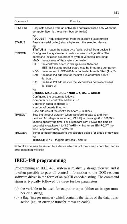
143
Command Function
REQUEST Requests service from an active bus controller (used only when thecomputer itself is the current bus controller)egREQUEST requests service from the current bus controller
STATUS Reads a (serial polled) status byte from the selected deviceegSTATUS 8 reads the status byte (serial polled) from device 8
SYSCON Configures the system for a particular user configuration. Thecommand initialises a number of system variables including:MAD the address of the system controllerCIC the controller board in charge (more than one
IEEE-488 bus controller board may be fitted to a computer)NOB the number of IEEE-488 bus controller boards fitted (1 or 2)BA0 the base I/O address for the first bus controller board
(ie, board 1)BA1 the base I/O address for the second bus controller board
(ie, board 2)egSYSCON MAD = 3, CIC = 1NOB = 1, BA0 = &H300Configures the system as follows:Computer bus controller address = 3Controller board in charge = 1Number of boards fitted = 1Base address of the controller board = 300 hex
TIMEOUT Sets the timeout duration when transferring data to and fromdevices. An integer number (eg, VAR%) in the range 0 to 65000 isused to specify the time. For a standard IBM-PC/XT the time (inseconds) is equivalent to 3.5∗VAR% whilst for an IBM-PC/AT thetime is approximately 1.5∗VAR%
TRIGGER Sends a trigger message to the selected device (or group of devices)egTRIGGER 9, 10 triggers devices 9 and 10
Note: If a command is issued by a device which is not the current controller then anerror condition will exist
IEEE-488 programming
Programming an IEEE-488 system is relatively straightforward and itis often possible to pass all control information to the DOS residentsoftware driver in the form of an ASCII encoded string. The commandstring is typically followed by three further parameters:
(a) the variable to be used for output or input (either an integer num-ber or a string)
(b) a flag (integer number) which contains the status of the data trans-action (eg, an error or transfer message code)
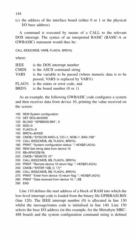
144
(c) the address of the interface board (either 0 or 1 or the physicalI/O base address)
A command is executed by means of a CALL to the relevantDOS interrupt. The syntax of an interpreted BASIC (BASIC-A orGWBASIC) statement would thus be:
CALL IEEE(CMD$, VAR$, FLAG%, BRD%)
where:
IEEE is the DOS interrupt numberCMD$ is the ASCII command stringVAR$ is the variable to be passed (where numeric data is to be
passed, VAR$ is replaced by VAR%)FLAG% is the status or error code, andBRD% is the board number (0 or 1)
As an example, the following GWBASIC code configures a systemand then receives data from device 10, printing the value received onthe screen:
100 REM System configuration110 DEF SEG=&H2000120 BLOAD ‘‘GPIBBASI.BIN’’, 0130 IEEE=0140 FLAG%=0150 BRD%=&H300160 CMD$=‘‘SYSCON MAD=3, CIC=1, NOB=1, BA0=768’’170 CALL IEEE(CMD$, A$, FLAG%, BRD%)180 PRINT ‘‘System configuration status: ’’; HEX$(FLAG%)200 REM Get string data from device 10210 B$=SPACE$(18)220 CMD$=‘‘REMOTE 10’’230 CALL IEEE(CMD$, B$, FLAG%, BRD%)240 PRINT ‘‘Remote device 10 return flag: ’’; HEX$(FLAG%)250 CMD$=‘‘ENTER 10[$, 0, 17]’’260 CALL IEEE(CMD$, B$, FLAG%, BRD%)270 PRINT ‘‘Enter from device 10 return flag: ’’; HEX$(FLAG%)280 PRINT ‘‘Data received from device 10: ’’; B$290 END
Line 110 defines the start address of a block of RAM into which thelow-level interrupt code is loaded from the binary file GPIBBASI.BIN(line 120). The IEEE interrupt number (0) is allocated in line 130whilst the message/status code is initialised in line 140. Line 150selects the base I/O address (in this example, for the Metrabyte MBC-488 board) and the system configuration command string is defined
145
in line 160 (note that the PC bus controller is given address 3 and asingle IEEE-488 bus interface board is present).
The status flag (returned after configuring the system by means ofthe CALL made in line 170) is displayed on the screen in hexadecimalformat (line 180). An empty string (B$) is initialised in line 210 (thiswill later receive the data return from device 10). Device 10 is selectedas the remote device in lines 220 and 230 whilst line 240 prints thereturned status flag for this operation. Data is then read from device10 (lines 250 and 260) and, finally, the status code and returned dataare displayed in lines 270 and 280.
In most cases, it will not be necessary to display returned statuscodes. However, it is usually necessary to check these codes in orderto ascertain whether a particular bus transaction has been successfuland that no errors have occurred. Furthermore, a more modern BASIC(eg, Microsoft QuickBASIC) will allow programmers to develop amore structured approach to controlling the IEEE-488 interface withcommand definitions, error checks, and CALLs consigned to sub-programs.
7 Communication protocols
Communication protocols are the sets of rules and formats necessaryfor the effective exchange of information within a data communi-cation system. The three elements of a communication protocol aresyntax (data format, coding, and signal level definitions), semantics(synchronisation, control, and error handling), and timing (sequencingof data and choice of data rate).
Communication protocols must exist on a range of levels, fromthe physical interconnection at one extreme to the application respon-sible for generating and processing the data at the other. It is useful,therefore, to think of protocols as layered, with each layer interactingwith the layers above and below. This is an important concept andone which leads directly to the ISO seven-layered model for OSI.
ISO model for open systems interconnection
The International Standards Organisation (ISO) model for open sys-tems interconnection (OSI) has become widely accepted as definingthe seven layers of protocol which constitute a communication sys-tem.
1. Physical layer
The physical layer describes the physical circuits which provide ameans of transmitting information between two users. The physicallayer is concerned with such items as line voltage levels and pinconnections
2. Data link layer
The data link layer defines protocols for transferring messages betweenthe host and network and vice versa. The layer is also responsible forflow control, error detection and link management
3. Network layer
The network layer supports network connections and routing betweentwo hosts and allows multiplexing of several channels via a commonphysical connection
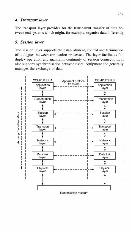
147
4. Transport layer
The transport layer provides for the transparent transfer of data be-tween end systems which might, for example, organise data differently
5. Session layer
The session layer supports the establishment, control and terminationof dialogues between application processes. The layer facilitates fullduplex operation and maintains continuity of session connections. Italso supports synchronisation between users’ equipment and generallymanages the exchange of data
Applicationlayer
Apparent protocoltransfers
Transmission medium
COMPUTER A
Presentationlayer
Sessionlayer
Transportlayer
Networklayer
Data linklayer
Physicallayer
Applicationlayer
COMPUTER B
Presentationlayer
Sessionlayer
Transportlayer
Networklayer
Data linklayer
Physicallayer
Act
ual p
roto
col t
rans
fers
148
6. Presentation layer
The presentation layer resolves the differences in representation ofinformation used by the application task so that each task can com-municate without knowing the representation of information used bya different task (eg, different data syntax)
7. Application layer
The application layer is the ultimate source and sink for data exchange.It provides the actual user information processing function and appli-cation specific services by translating user requests into specific net-work functions
NB: Layers 1 to 3 of the ISO model are often referred to ascommunication-oriented layers. Layers 5 to 7, on the other hand, arereferred to as application-oriented. In this context, the fourth layer canbe thought of as a bridge between the communication and application-oriented layers of the ISO model.
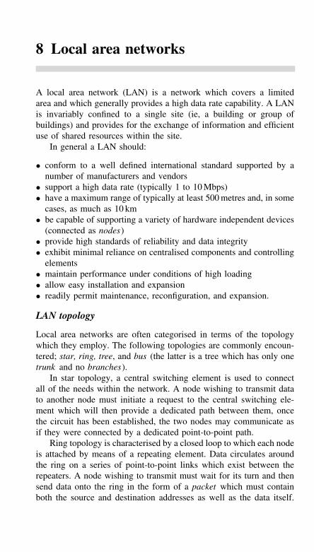
8 Local area networks
A local area network (LAN) is a network which covers a limitedarea and which generally provides a high data rate capability. A LANis invariably confined to a single site (ie, a building or group ofbuildings) and provides for the exchange of information and efficientuse of shared resources within the site.
In general a LAN should:
• conform to a well defined international standard supported by anumber of manufacturers and vendors
• support a high data rate (typically 1 to 10 Mbps)• have a maximum range of typically at least 500 metres and, in some
cases, as much as 10 km• be capable of supporting a variety of hardware independent devices
(connected as nodes)• provide high standards of reliability and data integrity• exhibit minimal reliance on centralised components and controlling
elements• maintain performance under conditions of high loading• allow easy installation and expansion• readily permit maintenance, reconfiguration, and expansion.
LAN topology
Local area networks are often categorised in terms of the topologywhich they employ. The following topologies are commonly encoun-tered; star, ring, tree, and bus (the latter is a tree which has only onetrunk and no branches).
In star topology, a central switching element is used to connectall of the needs within the network. A node wishing to transmit datato another node must initiate a request to the central switching ele-ment which will then provide a dedicated path between them, oncethe circuit has been established, the two nodes may communicate asif they were connected by a dedicated point-to-point path.
Ring topology is characterised by a closed loop to which each nodeis attached by means of a repeating element. Data circulates aroundthe ring on a series of point-to-point links which exist between therepeaters. A node wishing to transmit must wait for its turn and thensend data onto the ring in the form of a packet which must containboth the source and destination addresses as well as the data itself.
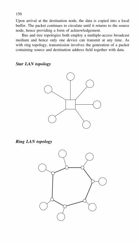
150
Upon arrival at the destination node, the data is copied into a localbuffer. The packet continues to circulate until it returns to the sourcenode, hence providing a form of acknowledgement.
Bus and tree topologies both employ a multiple-access broadcastmedium and hence only one device can transmit at any time. Aswith ring topology, transmission involves the generation of a packetcontaining source and destination address field together with data.
Star LAN topology
Ring LAN topology
151
Bus LAN topology
Tree LAN topology
Controlling/switching element
Key
Node (eg. computer)
Node access cable, transceiver drop, etc.
Transmission medium (shared)
Transmission medium with termination
Medium access unit, transceiver, etc.
Broadband and baseband transmission
Local area networks are available which support either broadband orbaseband transmission. In the former case, information is modulatedonto a radio frequency carrier which is passed through the transmis-sion medium (eg, coaxial cable). In the latter case, digital informationis passed directly through the transmission medium. It is importantto note that broadband LANs can exploit frequency division multi-plexing which allows a number of modulated radio frequency carriers(each with its own digital signal) to be simultaneously present withinthe transmission medium. Baseband LANs can only support one infor-mation signal at a time within the transmission medium.
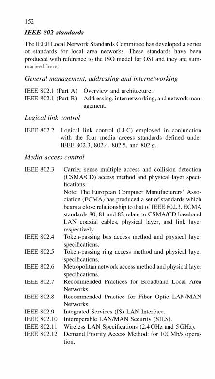
152
IEEE 802 standards
The IEEE Local Network Standards Committee has developed a seriesof standards for local area networks. These standards have beenproduced with reference to the ISO model for OSI and they are sum-marised here:
General management, addressing and internetworking
IEEE 802.1 (Part A) Overview and architecture.IEEE 802.1 (Part B) Addressing, internetworking, and network man-
agement.
Logical link control
IEEE 802.2 Logical link control (LLC) employed in conjunctionwith the four media access standards defined underIEEE 802.3, 802.4, 802.5, and 802.g.
Media access control
IEEE 802.3 Carrier sense multiple access and collision detection(CSMA/CD) access method and physical layer speci-fications.Note: The European Computer Manufacturers’ Asso-ciation (ECMA) has produced a set of standards whichbears a close relationship to that of IEEE 802.3. ECMAstandards 80, 81 and 82 relate to CSMA/CD basebandLAN coaxial cables, physical layer, and link layerrespectively
IEEE 802.4 Token-passing bus access method and physical layerspecifications.
IEEE 802.5 Token-passing ring access method and physical layerspecifications.
IEEE 802.6 Metropolitan network access method and physical layerspecifications.
IEEE 802.7 Recommended Practices for Broadband Local AreaNetworks.
IEEE 802.8 Recommended Practice for Fiber Optic LAN/MANNetworks.
IEEE 802.9 Integrated Services (IS) LAN Interface.IEEE 802.10 Interoperable LAN/MAN Security (SILS).IEEE 802.11 Wireless LAN Specifications (2.4 GHz and 5 GHz).IEEE 802.12 Demand Priority Access Method: for 100 Mb/s opera-
tion.
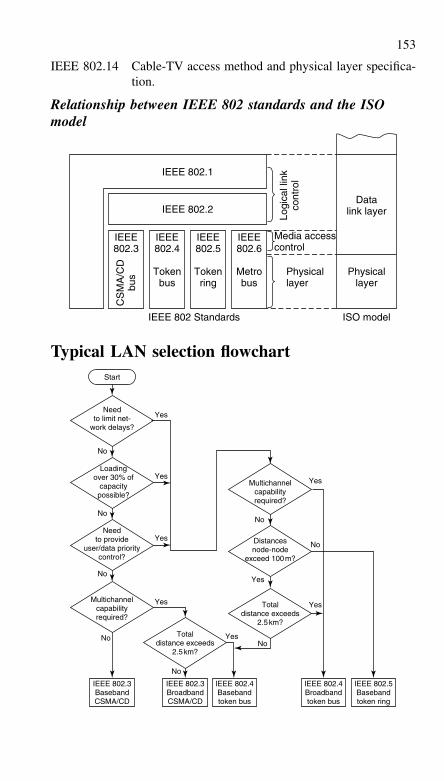
153
IEEE 802.14 Cable-TV access method and physical layer specifica-tion.
Relationship between IEEE 802 standards and the ISOmodel
IEEE 802.1
IEEE 802.2
IEEE802.3
CS
MA
/CD
bus
Logi
cal l
ink
cont
rol
IEEE 802 Standards
IEEE802.4
Tokenbus
IEEE802.5
Tokenring
IEEE802.6
Metrobus
Physicallayer
Physicallayer
ISO model
Datalink layer
Media accesscontrol
Typical LAN selection flowchart
Needto limit net-
work delays?
Start
Yes
Yes
Yes
No
No
No
Yes
Yes
Yes
Yes
Yes
NoNo
No
No
No
Loadingover 30% of
capacitypossible?
Needto provide
user/data prioritycontrol?
Multichannelcapabilityrequired?
IEEE 802.3BasebandCSMA/CD
IEEE 802.3BroadbandCSMA/CD
IEEE 802.4Basebandtoken bus
IEEE 802.4Broadbandtoken bus
IEEE 802.5Basebandtoken ring
Totaldistance exceeds
2.5km?
Totaldistance exceeds
2.5km?
Distancesnode-node
exceed 100m?
Multichannelcapabilityrequired?
154
Popular network standards
Ethernet
The Ethernet standard follows IEEE 802.3 and has been widelyaccepted by a number of independent systems suppliers. Ethernet’spopularity stems from a number of factors including the availabilityof VLSI controllers which permit cost-effective implementation of anetwork and the high data rate of 10 Mbps.
The Ethernet link control layer employs carrier sense multipleaccess with collision detection (CSMA/CD) and an HDLC-type framestructure is employed. Basic network physical layer componentscomprise coaxial cables for transmission media (maximum segmentlength 500 metres), transceivers with collision detection circuitry,a transceiver drop cable (maximum length 50 metres) whichconnects data terminal equipment to a nearby transceiver unit,and a controller board. This latter device is responsible for frameassembly/disassembly, handling source and destination addressing,detection of physical transmission errors, collision detection andretransmission.
Where network distances are to exceed 500 metres, multiple seg-ments are employed and these are linked by means of repeaters.Point-to-point links are used to link together segments which are sep-arated by physical distances of up to 1 km. Such links act as a repeaterdivided into two sections.
Ethernet packet format and LAN management is used in 10 Base-T,100 Base-T and Gigabit Ethernet systems.
Cheapernet
Cheapernet also follows IEEE 802.3 but provides a low-cost alter-native to Ethernet in which the transceiver function is incorporatedwithin the terminal equipment (the cable tap box and transceivercable are thus no longer required). Savings in cost are also madeby using lower grade coaxial cable throughout the network and ter-minal equipment is simply attached using T-connectors at strategicpoints. Cheapernet is thus very much simpler to install than its moreexpensive counterpart.
155
The limitations of Cheapernet are that its segment length isrestricted to 185 metres (making repeaters essential for largernetworks) and that the IEEE 802.3 cable/terminal ground isolationscheme (which requires d.c. isolation between transceiver andterminal) is not so easy to implement using VLSI devices when thetransceiver function is to be integrated within the controller. Thesetwo drawbacks can seriously limit the cost-effectiveness of the systemwhen compared with a full Ethernet implementation of IEEE 802.3.
Baseband IBM PC LAN
The baseband IBM PC LAN allows a mixture of PCs and PS/2machines to communicate with one another at relatively low-cost.A PC network adaptor/A, network support program, and PC LANprogram is required at each node. CSMA/CD protocol is used andthe network employs a twisted pair cable in which the data rate is2 Mbps.
Broadband IBM PC LAN
The broadband IBM PC LAN also allows a mixture of PCs and PS/2machines to communicate with one another with the aid of a PC net-work adaptor II/A, network support program and PC LAN programat each node. In addition, one or more PC network translator unitsare required. Each translator unit can handle up to eight nodes at dis-tances not exceeding 200 feet. Larger networks can be realised usingfurther translators and standard IBM Cable System components. Thebroadband PC LAN operates at a data rate of 2 Mbps with CSMA/CDprotocol and coaxial cable.
IBM Token Ring LAN
The IBM Token Ring LAN can be used to implement a lager networkin which computer systems (eg, System/370) can communicate witha variety of PC and PS/2 machines. Token ring network adaptorsare required at each PC or PS/2 node together with one or moremulti-station access units. The data transfer rate for the network is4 Mbps.
156
ICL Macrolan
ICL Macrolan employs a modified form of token-passing ring whichincorporates features designed to improve the efficiency and fault tol-erance of the system. The system uses optical fibres as the physicalmedium with multi-port ring switches which permit disconnection ofinactive nodes. Two optical cables are required for each node in orderto permit full duplex operation.
Manufacturing Automation Protocol (MAP)
Manufacturing Automation Protocol (MAP) is a broadband token bussystem which uses community television (CATV) coaxial cable as itsphysical medium. The standard was developed by General Motorsbut has become widely accepted by a number of major manufacturingand production engineering concerns as a robust and versatile factorynetworking standard.
The layers within MAP closely follow the ISO model for OSI(there is direct correspondence at the application, session, transport,network, data link and physical levels). The data link layer followsIEEE 802.2 while the physical layer corresponds to the IEEE 802.4(token bus) standard. The system employs quadrature amplitude mod-ulation (QAM) at a data rate of 10 Mbps.
Technical and Office Protocol (TOP)
Technical and Office Protocol (TOP) was developed by Boeing Com-puter Services and has much in common with MAP. TOP can, how-ever, be implemented at lower cost using the CSMA/CD protocoldefined under IEEE 802.3. The upper layers of TOP correspond closelyto those within MAP and thus it is possible to interwork the two sys-tems. TOP version 1.1 employs standard Ethernet trunk coaxial cablewith a maximum segment length of 500 metres (adequate for mostoffice and commercial environments). A routing device (or router)permits interconnection of MAP and TOP networks. The routingdevice essentially provides a bridge above layer of the ISO model andresolves any differences between address domains, frame sizes, etc.
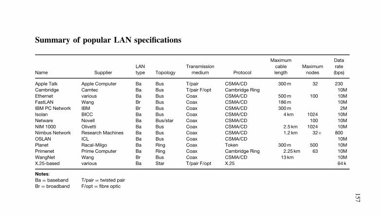
157
Summary of popular LAN specifications
Name SupplierLANtype Topology
Transmissionmedium Protocol
Maximumcablelength
Maximumnodes
Datarate(bps)
Apple Talk Apple Computer Ba Bus T/pair CSMA/CD 300 m 32 230Cambridge Camtec Ba Bus T/pair F/opt Cambridge Ring 10MEthernet various Ba Bus Coax CSMA/CD 500 m 100 10MFastLAN Wang Br Bus Coax CSMA/CD 186 m 10MIBM PC Network IBM Br Bus Coax CSMA/CD 300 m 2MIsolan BICC Ba Bus Coax CSMA/CD 4 km 1024 10MNetware Novell Ba Bus/star Coax CSMA/CD 100 10MNIM 1000 Olivetti Ba Bus Coax CSMA/CD 2.5 km 1024 10MNimbus Network Research Machines Ba Bus Coax CSMA/CD 1.2 km 32+ 800OSLAN ICL Ba Bus Coax CSMA/CD 10MPlanet Racal-Milgo Ba Ring Coax Token 300 m 500 10MPrimenet Prime Computer Ba Ring Coax Cambridge Ring 2.25 km 63 10MWangNet Wang Br Bus Coax CSMA/CD 13 km 10MX.25-based various Ba Star T/pair F/opt X.25 64 k
Notes:Ba = baseband T/pair = twisted pairBr = broadband F/opt = fibre optic
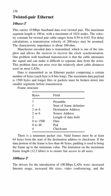
158
Twisted-pair Ethernet
10base-T
This carries 10 Mbps baseband data over twisted pair. The maximumsegment length is 100 m, with a maximum of 1024 nodes. The veloc-ity constant for twisted pair cable ranges from 0.59 to 0.63. For delaycalculations, a transmission velocity of 200 m/µs may be assumed.The characteristic impedance is about 100 ohm.
Manchester encoded data is transmitted, which is one of the sim-plest and allows the receiver to recover the clock synchronisation.One problem with baseband transmission is that the cable attenuatesthe signal and can make it difficult to separate data from the noise.This problem does not arise over the relatively short cable distancesused on most LANs.
Data is transmitted as an Ethernet packet comprising a certainnumber of bytes (each byte is 8-bits long). The maximum data payloadis 1500 bytes and longer files or packets must be broken down intosmaller segments before transmission.
Frame structure
Bytes Field
7 Preamble1 Start of frame delimiter2 or 6 Destination Address2 or 6 Source Address2 Length of data field0 to 1500 Data0 to 46 Pad4 Checksum
There is a minimum packet size. Valid frames must be at least64 bytes from the start of the destination address to checksum. If thedata portion of the frame is less than 46 bytes, padding is used to bringthe frame up to the minimum value. The limitation on the maximumframe length (12.2 kbits) is to ensure fair access to all users.
100base-T
The drivers for the introduction of 100 Mbps LANs were: increasedInternet usage, increased file sizes, video conferencing, and the
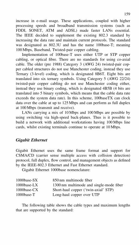
159
increase in e-mail usage. These applications, coupled with higherprocessing speeds and broadband transmission systems (such asFDDI, SONET, ATM and ADSL) made faster LANs essential.The IEEE decided to supplement the existing 802.3 standard byincreasing the data rate and maintain current protocols. The standardwas designated as 802.3U and has the name 100base-T; meaning100 Mbps, Baseband, Twisted-pair copper cabling.
Implementation of 100base-T uses either UTP or STP coppercabling, or optical fibre. There are no standards for using co-axialcable. The older (pre 1988) Category 3 (AWG 24) twisted-pair cop-per cabled structures do not use Manchester coding, instead they useTernary (3-level) coding, which is designated 8B6T. Eight bits aretranslated into six ternary symbols. Using Category 5 (AWG 22/24)twisted-pair copper cabling do not use Manchester coding either,instead they use binary coding, which is designated 4B5B (4 bits aretranslated into 5 binary symbols, which means that the cable data rateexceeds the system data rate). In this scheme, 100baseTX can clockdata over the cable at up to 125 Mbps and can perform as full duplexat 100 Mbps (transmit and receive).
LANs carrying a mix of 10 Mbps and 100 Mbps are possible byusing switching via high-speed back-planes. Thus is it possible tobuild a network with additional workstations having 100 Mbps linecards, whilst existing terminals continue to operate at 10 Mbps.
Gigabit Ethernet
Gigabit Ethernet uses the same frame format and support forCSMA/CD (carrier sense multiple access with collision detection)protocol, full duplex, flow control, and management objects as definedby the IEEE-802.3 Ethernet and Fast Ethernet standard.
Gigabit Ethernet 1000base nomenclature:
1000base-SX 850 nm multimode fiber1000base-LX 1300 nm multimode and single-mode fiber1000base-CX Short-haul copper (‘twin-axial’ STP)1000base-T Long-haul copper over UTP
The following table shows the cable types and maximum lengthsthat are supported by the standard:
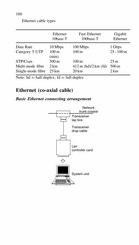
160
Ethernet cable types
Ethernet Fast Ethernet Gigabit10base-T 100base-T Ethernet
Data Rate 10 Mbps 100 Mbps 1 GbpsCategory 5 UTP 100 m
(min)100 m 25–100 m
STP/Coax 500 m 100 m 25 mMulti-mode fibre 2 km 412 m (hd)/2 km (fd) 500 mSingle-mode fibre 25 km 20 km 2 km
Note: hd = half-duplex; fd = full-duplex
Ethernet (co-axial cable)
Basic Ethernet connecting arrangement
Networktrunk coaxial
Transceivertap box
Transceiverdrop cable
Lancontroller card
System unit
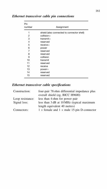
161
Ethernet transceiver cable pin connections
Pinnumber Assignment
1 shield (also connected to connector shell)2 collision+3 transmit+4 reserved5 receive+6 power7 reserved8 reserved9 collision
10 transmit11 reserved12 receive13 power+14 reserved15 reserved
Ethernet transceiver cable specifications
Construction: four-pair 78 ohm differential impedance plusoverall shield (eg, BICC H9600)
Loop resistance: less than 4 ohm for power pairSignal loss: less than 3 dB at 10 MHz (typical maximum
length equivalent 40 metres)Connectors: 1 × female and 1 × male 15-pin D-connector
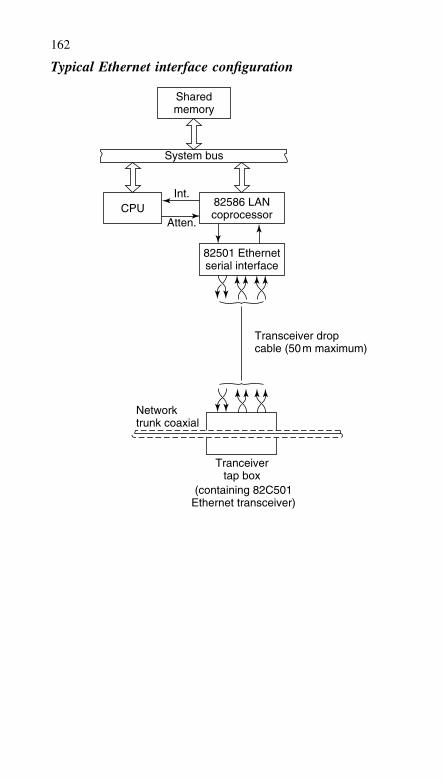
162
Typical Ethernet interface configuration
Sharedmemory
System bus
Int.
Atten.CPU 82586 LAN
coprocessor
82501 Ethernetserial interface
Transceiver dropcable (50m maximum)
Networktrunk coaxial
Tranceivertap box
(containing 82C501Ethernet transceiver)
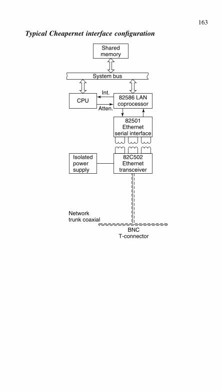
163
Typical Cheapernet interface configuration
Sharedmemory
System bus
CPUInt.
Atten.
82586 LANcoprocessor
82501Ethernet
serial interface
82C502Ethernet
transceiver
BNCT-connector
Isolatedpowersupply
Networktrunk coaxial
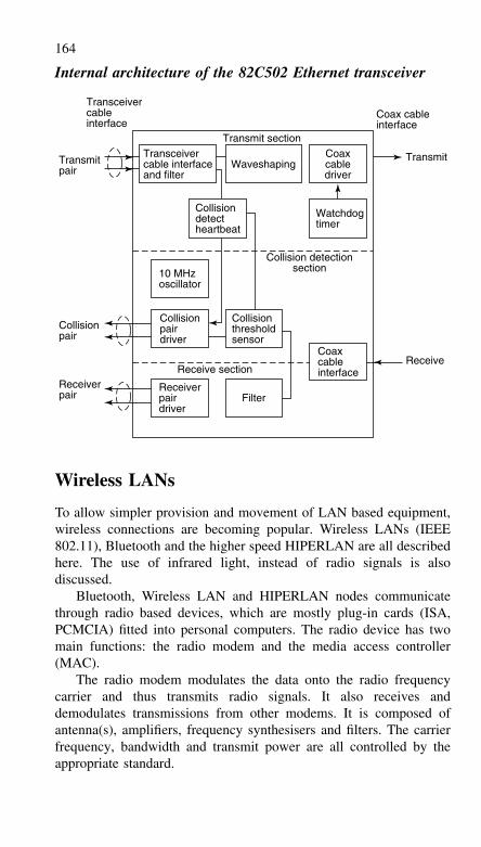
164
Internal architecture of the 82C502 Ethernet transceiver
Transceivercable interfaceand filter
Transceivercable interface
Transmitpair
Collisionpair
Receiverpair
Collisiondetectheartbeat
10 MHzoscillator
Collisionpairdriver
Receiverpairdriver
Filter
Receive section
Collisionthresholdsensor
Coaxcableinterface
Collision detectionsection
Waveshaping
Transmit sectionCoaxcabledriver
Coax cableinterface
Transmit
Receive
Watchdogtimer
Wireless LANs
To allow simpler provision and movement of LAN based equipment,wireless connections are becoming popular. Wireless LANs (IEEE802.11), Bluetooth and the higher speed HIPERLAN are all describedhere. The use of infrared light, instead of radio signals is alsodiscussed.
Bluetooth, Wireless LAN and HIPERLAN nodes communicatethrough radio based devices, which are mostly plug-in cards (ISA,PCMCIA) fitted into personal computers. The radio device has twomain functions: the radio modem and the media access controller(MAC).
The radio modem modulates the data onto the radio frequencycarrier and thus transmits radio signals. It also receives anddemodulates transmissions from other modems. It is composed ofantenna(s), amplifiers, frequency synthesisers and filters. The carrierfrequency, bandwidth and transmit power are all controlled by theappropriate standard.
165
To overcome noise and to increase the reliability of wirelessLAN systems, diversity in terms of frequency, space or time isused. Spread spectrum is a form of frequency diversity because ituses more bandwidth than necessary to avoid noisy parts of thespectrum. Retransmission and Forward Error Correction (FEC) of thetransmitted signals give temporal diversity. Spatial diversity in a radiosystem is achieved by using two or more antennas, to provide twopaths for the radio signal.
Media access control (MAC)
The MAC is responsible for running the signalling protocol, which isalso determined by the appropriate standard. The main characteristicsof the MAC protocol are packet format (size, headers), channelaccess mechanisms and network management. The two channel accessmechanisms used by the MAC protocol in wireless LAN systemsare carrier sense multiple access/collision avoidance (CSMA/CA) andPolling MAC.
CSMA/CA is the channel access mechanism used by mostwireless LANs in the ISM bands. A channel access mechanismis the part of the protocol that specifies when to listen, when totransmit. The basic principles of CSMA/CA are listen before talkand contention. This is an asynchronous message passing mechanism(connectionless), delivering a best effort service, but no bandwidthand latency guarantee. Its main advantages are that it is suited fornetwork protocols such as TCP/IP, adapts quite well to variable trafficconditions and is quite robust against interference.
CSMA/CA is derived from CSMA/CD (collision detection), whichat the heart of Ethernet MAC: the main difference between them isthe carrier sense function. On a wire, the transceiver has the abilityto listen whilst transmitting and hence can detect collisions. But awireless system cannot listen on the channel whilst transmitting, sincetransmit and receive frequencies are the same and because the transmitlevel is far higher than the receive level. Therefore the wireless MACprotocol tries to avoid, instead of detecting, collisions.
The protocol starts by listening on the channel (this is calledcarrier sense) and, if the channel is found to be idle, sends the firstpacket in the transmit queue. If it is busy, due to either another nodetransmission or interference, the node waits until the end of the currenttransmission and then starts the contention (waits a random amountof time). When its contention timer expires, if the channel is stillidle, the node sends the packet. The node having chosen the shortest
166
contention delay wins and transmits its packet. Because the contentionis a random number, each node is given an equal chance to accessthe channel (on average).
A form of carrier sense used by some systems is request tosend/clear to send (RTS/CTS). The RTS/CTS is a handshakingprotocol: before sending a packet, the transmitter sends a RTS andwaits for CTS from the receiver. The reception of CTS indicates thatthe receiver is able to receive the RTS, so the packet may then betransmitted (the channel is clear in its area). Any node within rangeof the receiver hears the CTS and so knows that a transmission isabout to take place.
The RTS and CTS messages contain the size of the expected trans-mission, so any node listening will know how long the transmissionwill last. This is useful because the data transmission itself may notbe heard. The use of RTS/CTS lowers the overhead of a collision onthe medium, because RTS collisions are much shorter in time. If twonodes attempt to transmit in the same slot of the contention window,their RTS collide and they have to try again. They loose an RTSinstead of a whole packet.
Polling is a major channel access mechanism. The 802.11 stand-ard offers a polling channel access mechanism (point co-ordinationfunction) in addition to the CSMA/CA one. Polling is a mixture ofboth time division multiple access (TDMA) and CSMA/CA. TDMAis not used because although it is ideal for voice traffic (which is whyit is used by GSM) it is not suitable for IP traffic that occurs in bursts.In the polling access scheme, the base station retains total control overthe channel but the frame content is no longer fixed, allowing variablesize packets to be sent. The base station sends a short ‘poll packet’ totrigger the transmission by the node. The node just waits to receive apoll packet and, upon reception, starts data transmission.
Error control
There is a higher error rate on the radio link than over a wire andthis leads to packets being corrupted. Packet losses at the MAC layercause problems for TCP, so most MAC protocols implement positiveacknowledgments and MAC level retransmissions. Each time a nodesuccessfully receives a packet, it immediately sends back a short mes-sage (an ACK) to the transmitter. If the transmitter does not receive anACK within a certain period after sending a packet, it will retransmitthe message.
Some wireless LAN systems use fragmentation to increase the datathroughput on an error-prone radio channel. Fragmentation involves
167
breaking down big packets into small pieces before transmitting them.This adds some overhead, because packet headers are duplicated inevery fragment. Each fragment is individually checked and retrans-mitted if necessary. In case of a corrupted packet being received, thenode need only retransmit one small fragment, so it is faster.
Industrial scientific and medical (ISM) band
Wireless LANs and bluetooth both use the industrial scientific andmedical (ISM) frequency band at 2.4 GHz. The ITU has decreed thatthis band may be used for ISM purposes in all parts of the world. How-ever, national regulators deal with specific licensing. In Europe, allequipment operating in these bands must comply with ETSI standardETS 300 328. In the USA, any WLAN operating in this band mustcomply with FCC part 15. In Japan, compliance with MPT (Ministryof Post & Telecommunications) ordinance 79 is necessary. However,ISM bands are unlicensed, which means that a large number of otherusers may be using the same frequencies. The 2.4 GHz band alsosuffers from microwave oven radiation.
The ISM band regulations specify that spread spectrum techniqueshave to be used (either direct sequence or frequency hopping). Thesetechniques spread the signal over a large bandwidth to reduce localisedinterference. The radio modem used for direct sequence is more com-plicated than the frequency hopping one, but the direct sequencemethod requires a simpler media access control (MAC) protocol. Fre-quency hopping is more resistant to interference, but direct sequenceoffers better performance when multi-path propagation is a problem.Frequency hopping is normally used.
The ISM band regulations limit the radio bandwidth to 1 MHz forfrequency hopping systems. The available data rate can be increased bycomplex modulation schemes, allowing several data bits per symbol.This means that the receiver has to distinguish between a number ofdifferent symbols. To do this, the signal-to-noise ratio of the receivedsignal has to be higher than if a simple two-symbol system wereoperating. Since the various standards limit the transmitter power level,the operating range is reduced.
Bluetooth
Bluetooth also operates in the 2.4 GHz license-exempt Industrial, Sci-entific and Medical (ISM) band. Bluetooth uses frequency hopping
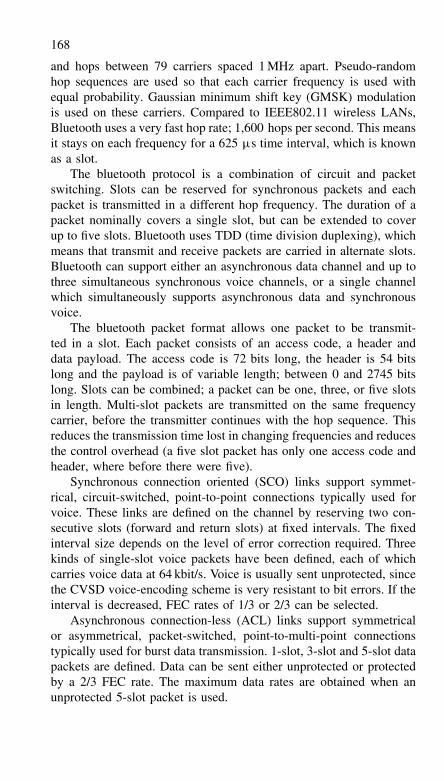
168
and hops between 79 carriers spaced 1 MHz apart. Pseudo-randomhop sequences are used so that each carrier frequency is used withequal probability. Gaussian minimum shift key (GMSK) modulationis used on these carriers. Compared to IEEE802.11 wireless LANs,Bluetooth uses a very fast hop rate; 1,600 hops per second. This meansit stays on each frequency for a 625 µs time interval, which is knownas a slot.
The bluetooth protocol is a combination of circuit and packetswitching. Slots can be reserved for synchronous packets and eachpacket is transmitted in a different hop frequency. The duration of apacket nominally covers a single slot, but can be extended to coverup to five slots. Bluetooth uses TDD (time division duplexing), whichmeans that transmit and receive packets are carried in alternate slots.Bluetooth can support either an asynchronous data channel and up tothree simultaneous synchronous voice channels, or a single channelwhich simultaneously supports asynchronous data and synchronousvoice.
The bluetooth packet format allows one packet to be transmit-ted in a slot. Each packet consists of an access code, a header anddata payload. The access code is 72 bits long, the header is 54 bitslong and the payload is of variable length; between 0 and 2745 bitslong. Slots can be combined; a packet can be one, three, or five slotsin length. Multi-slot packets are transmitted on the same frequencycarrier, before the transmitter continues with the hop sequence. Thisreduces the transmission time lost in changing frequencies and reducesthe control overhead (a five slot packet has only one access code andheader, where before there were five).
Synchronous connection oriented (SCO) links support symmet-rical, circuit-switched, point-to-point connections typically used forvoice. These links are defined on the channel by reserving two con-secutive slots (forward and return slots) at fixed intervals. The fixedinterval size depends on the level of error correction required. Threekinds of single-slot voice packets have been defined, each of whichcarries voice data at 64 kbit/s. Voice is usually sent unprotected, sincethe CVSD voice-encoding scheme is very resistant to bit errors. If theinterval is decreased, FEC rates of 1/3 or 2/3 can be selected.
Asynchronous connection-less (ACL) links support symmetricalor asymmetrical, packet-switched, point-to-multi-point connectionstypically used for burst data transmission. 1-slot, 3-slot and 5-slot datapackets are defined. Data can be sent either unprotected or protectedby a 2/3 FEC rate. The maximum data rates are obtained when anunprotected 5-slot packet is used.
169
Type of packet Symmetric (kbit/s) Asymmetric (kbit/s)
1-slot (protected) 108.8 108.8/108.81-slot (unprotected) 172.8 172.8/172.83-slot (protected) 256.0 384.0/54.43-slot (unprotected) 384.0 576.0/86.45-slot (protected) 286.7 477.8/36.35-slot (unprotected) 432.6 721.0 (max)/57.6
The packet definitions have been kept flexible as to whether or notto use FEC in the payload. The packet header is always protected by a1/3 rate FEC, this is because it contains valuable link information thatneeds to survive bit errors. For data transmission, an ARQ scheme isapplied.
The 5 GHz band (HIPERLAN and IEEE802.11)
HIPERLAN and satellite systems use the 5 GHz band. The band from5.15 to 5.25 GHz (three radio channels) is available across Europe,with 5.25 to 5.35 GHz (two extra channels) also available in somecountries, but not in the UK. These bands may be used indoors by bothHIPERLAN/1 and HIPERLAN/2, and transmitted power is limited to200 mW.
HIPERLAN/2 systems use the band 5470–5725 MHz, bothindoors and outdoors, although transmitted power is limited to1 W. In order to co-exist with satellite feeder links, HIPERLAN/2systems using this band must incorporate power control and dynamicfrequency selection. HIPERLAN/1 systems do not have these facilitiesand therefore cannot be used here since they would risk causinginterference to satellite systems.
In the USA, three U-NII bands are specified. These have veryliberal rules – spread spectrum is not mandated. No channels havebeen allocated and there are different power maximums, dependingon the band being used. The low band covers 5.15 to 5.25 GHz, themid band covers 5.25 to 5.35 GHz and the high band covers 5.725 to5.825 GHz.
In Japan, 5.725–5.875 GHz is set aside for ISM applications, suchas wireless LANs.
In the 5 GHz band, higher speeds are possible because of theavailability of more bandwidth. This is typically 10 to 40 Mb/s (whichin theory is also available in the 2.4 GHz band). The disadvantage with
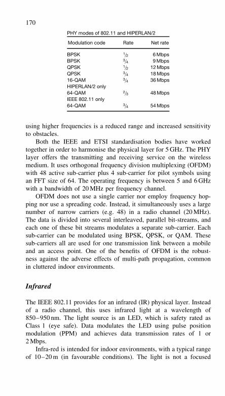
170
PHY modes of 802.11 and HIPERLAN/2
Modulation code Rate Net rate
BPSK 1/2 6 MbpsBPSK 3/4 9 MbpsQPSK 1/2 12 MbpsQPSK 3/4 18 Mbps16-QAM 3/4 36 MbpsHIPERLAN/2 only64-QAM 2/3 48 MbpsIEEE 802.11 only64-QAM 3/4 54 Mbps
using higher frequencies is a reduced range and increased sensitivityto obstacles.
Both the IEEE and ETSI standardisation bodies have workedtogether in order to harmonise the physical layer for 5 GHz. The PHYlayer offers the transmitting and receiving service on the wirelessmedium. It uses orthogonal frequency division multiplexing (OFDM)with 48 active sub-carrier plus 4 sub-carrier for pilot symbols usingan FFT size of 64. The operating frequency is between 5 and 6 GHzwith a bandwidth of 20 MHz per frequency channel.
OFDM does not use a single carrier nor employ frequency hop-ping nor use a spreading code. Instead, it simultaneously uses a largenumber of narrow carriers (e.g. 48) in a radio channel (20 MHz).The data is divided into several interleaved, parallel bit-streams, andeach one of these bit streams modulates a separate sub-carrier. Eachsub-carrier can be modulated using BPSK, QPSK, or QAM. Thesesub-carriers all are used for one transmission link between a mobileand an access point. One of the benefits of OFDM is the robust-ness against the adverse effects of multi-path propagation, commonin cluttered indoor environments.
Infrared
The IEEE 802.11 provides for an infrared (IR) physical layer. Insteadof a radio channel, this uses infrared light at a wavelength of850–950 nm. The light source is an LED, which is safety rated asClass 1 (eye safe). Data modulates the LED using pulse positionmodulation (PPM) and achieves data transmission rates of 1 or2 Mbps.
Infra-red is intended for indoor environments, with a typical rangeof 10–20 m (in favourable conditions). The light is not a focused
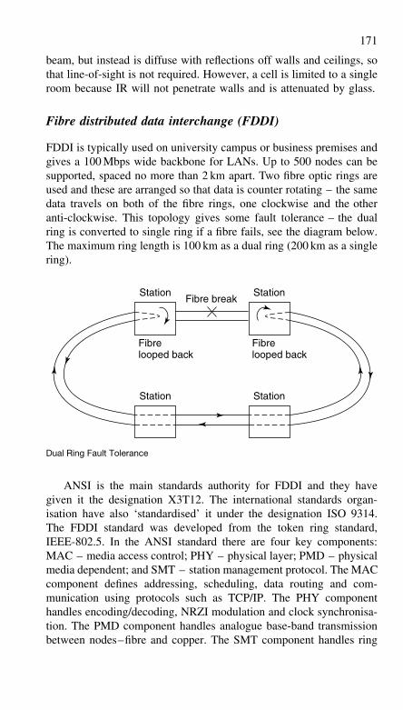
171
beam, but instead is diffuse with reflections off walls and ceilings, sothat line-of-sight is not required. However, a cell is limited to a singleroom because IR will not penetrate walls and is attenuated by glass.
Fibre distributed data interchange (FDDI)
FDDI is typically used on university campus or business premises andgives a 100 Mbps wide backbone for LANs. Up to 500 nodes can besupported, spaced no more than 2 km apart. Two fibre optic rings areused and these are arranged so that data is counter rotating – the samedata travels on both of the fibre rings, one clockwise and the otheranti-clockwise. This topology gives some fault tolerance – the dualring is converted to single ring if a fibre fails, see the diagram below.The maximum ring length is 100 km as a dual ring (200 km as a singlering).
Fibrelooped back
Station Station
Station Station
Fibrelooped back
Fibre break
Dual Ring Fault Tolerance
ANSI is the main standards authority for FDDI and they havegiven it the designation X3T12. The international standards organ-isation have also ‘standardised’ it under the designation ISO 9314.The FDDI standard was developed from the token ring standard,IEEE-802.5. In the ANSI standard there are four key components:MAC – media access control; PHY – physical layer; PMD – physicalmedia dependent; and SMT – station management protocol. The MACcomponent defines addressing, scheduling, data routing and com-munication using protocols such as TCP/IP. The PHY componenthandles encoding/decoding, NRZI modulation and clock synchronisa-tion. The PMD component handles analogue base-band transmissionbetween nodes–fibre and copper. The SMT component handles ring
172
management including neighbour identification, fault detection andreconfiguration.
FDDI cables usually employ multi-mode fibre with a 62.5 microncore and 125 micron cladding diameter. The 62.5/125 fibre isfavoured because low-cost LED/photodiode technology can be usedto drive/detect light in wider fibre. However, 50/125, 85/125 andsingle mode fibre can also be supported. Four fibres are used in eachcable (2 transmit and 2 receive) although the installation of spares isrecommended for replacement of faulty fibres.
It is also possible to use FDDI formatted data over copper, whichhas the acronym CuDDI. This uses copper unshielded twisted pair(UTP) or shielded twisted pair (STP) cables for connecting to localterminals. The copper cable can be up to 100 metres in length andANSI standard TP–PMD (twisted pair–physical medium dependent)applies. The advantages of using twisted pair cable are that it is lowcost and that installation and termination are simpler. Also, copperbased transceivers are cheaper, smaller and require less power com-pared to fibre-based systems.
Unlike token rings defined by IEEE 802.5, there is no active ringmonitor. Instead, each ring interface has its own clock synchronisedto incoming data. The outgoing data is transmitted using a local clock.FDDI is not synchronous but is plesiochronous.
All data is encoded prior to transmission and this uses a 4-out-of-5-group code known as 4B/5B. In this scheme, every 4-bit group(16 different combinations) is mapped onto a 5-bit code (symbol).The 5-bit symbols for 4-bit data groups are chosen such that no morethan two successive zeros occur. Certain 5-bit symbols that are notused for data encoding are used instead as control symbols. The 5-bitsymbols are passed through a NRZI (non return to zero inverter) whichproduces a signal transition for logic 1 and no change for logic 0.The 4B/5B encoding combined with NZRI modulation guarantees thatthere is one signal transition at least for every three bits transmitted.
The control symbols are abbreviated to characters I, H, Q, J, K,T, R, S and L. Control symbols I, H and Q give the fibre state:I = idle = 11111, H = halt = 00100, Q = quiet = 00000. Symbols J,K and T are used as frame delimiters. Symbols R and S are logicalindicators (‘0’, ‘1’), and L is reserved for FDDI version II.
In an idle FDDI system, a ‘token’ is transmitted around the ringcontinuously. Each station receives the token and then re-transmitsit into the ring. When a station wishes to transmit a data packet, itmust ‘capture’ the token first. A token is captured when it has beenreceived by a station, but not re-transmitted. Once a station holds
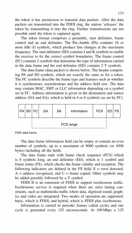
173
the token it has permission to transmit data packets. After the datapackets are transmitted into the FDDI ring, the station ‘releases’ thetoken by transmitting it into the ring. Further transmissions are notpossible until the token is captured again.
The token format comprises a preamble, start delimiter, framecontrol and an end delimiter. The Pre-Amble (PA) contains 16 ormore Idle (I) symbols, which produce line changes at the maximumfrequency. The start delimiter (SD) contains J and K symbols to enablethe receiver to fix the correct symbol boundaries. The frame control(FC) contains 2 symbols that determine the type of information carriedin the data frame and the end delimiter (ED) contains 2 T symbols.
The data frame (data packet) is shown below. The header compris-ing PA and SD symbols, which are exactly the same as for a token.The FC symbols describe the frame type and features such as whetherit is synchronous, asynchronous and the address field size. The datamay contain MAC, SMT or LLC information depending on a symbolset in FC. Address information is given in the destination and sourceaddress (DA and SA), which is held in 4 or 8 symbols (as set by FC).
PA SD FC DA SA FCS ED FSInformation
FCS range
FDDI data frame
The data frame information field can be empty or contain an evennumber of symbols, up to a maximum of 9000 symbols (or 4500bytes) including all the fields.
The data frame ends with frame check sequence (FCS) whichis 8 symbols long, an end delimiter (ED), which is 1 symbol andframe status (FS), which checks the frame validity and reception. Thefollowing indicators are defined in the FS field: E = error detected,A = address recognised, and C = frame copied. Other symbols maybe added possibly followed by a T symbol.
FDDI II is an extension of FDDI to support isochronous traffic.Isochronous service is required when there are strict timing con-straints, such as multimedia traffic where data, digitised sound, graph-ics and video are integrated. Two modes of operation are supported:basic, which is FDDI, and hybrid, which is FDDI plus isochronous.
Information is carried in periodic frames called cycles and onecycle is generated every 125 microseconds. At 100 Mbps a 125
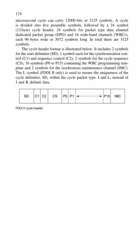
174
microsecond cycle can carry 12000 bits or 3125 symbols. A cycleis divided into five preamble symbols, followed by a 24 symbol(12 byte) cycle header, 24 symbols for packet type data channeldedicated packet group (DPG) and 16 wide-band channels (WBCs),each 96 bytes wide or 3072 symbols long. In total there are 3125symbols.
The cycle header format is illustrated below. It includes 2 symbolsfor the start delimiter (SD), 1 symbol each for the synchronisation con-trol (C1) and sequence control (C2), 2 symbols for the cycle sequence(CS), 16 symbols (P0 to P15) containing the WBC programming tem-plate and 2 symbols for the isochronous maintenance channel (IMC).The L symbol (FDDI II only) is used to ensure the uniqueness of thecycle delimiter, SD, within the cycle packet type. I and L, instead ofJ and K delimit data.
SD C1 C2 CS P0 P1 P15 IMC
FDDI II cycle header
9 Wide area networks
Wide area networks (WANs) occur when two or more local area net-works (LANs) are joined over a long-distance link. This link requiresa digital access from the local telephone exchange, and this can beprovided by a conventional (e.g. V.34) modem, a DSL modem orISDN terminal. Where an E1 or T1 trunk is provided, data is oftentransmitted in ATM packets.
Connecting LANs
The connection between a LAN and an external transmission path isvia a gateway. The gateway is either a router or a server fitted withline termination cards. When it is necessary to transmit data over the‘wide-area’ link, the gateway opens a connection and performs all thenecessary data rate and protocol adaption. Usually, the wide-area linkis not capable of transmitting data as fast as it is transmitted overthe LAN. For example, a 100 Mbps LAN may only have a 2 Mbpswide-area link. Data is collected by the gateway at the LAN speedand then forwarded at the speed of the wide-area link. Gateways arealso used to provide a ‘firewall’, to control access and ensure thatviruses are not transferred between LANs.
Integrated services digital network
Most telecommunications providers use an integrated digital network.However, the service extended to the user is often analogue, withdigital to analogue conversion taking place in the local exchange.Digital service is available, but the cost is usually higher becauseexpensive line termination equipment is required. The digital serviceis called integrated services digital network (ISDN). The InternationalTelecommunications Union – Telecommunications sector (ITU-T) haspublished a series of recommendations for ISDN, called the I-series.The I.100 series gives general information, such as basic descriptionsand definitions of terms. The I.200 series describes services, whilstthe I.300 series describes the network capabilities.
There are two systems: basic rate and primary rate ISDN. Basicrate provides two 64 kbps circuits, known as B-channels (B = basic)and is known as ISDN2. These circuits can be coupled to provide a
176
single 128 kbps circuit. A 16 kbps control (or signalling) channel isalso provided and this is known as the D-channel. Thus ISDN2 is alsoreferred to as 2B + D, basic rate ISDN or even IDSL.
Primary rate ISDN is defined under ITU-T recommendation I.431as a 30-channel service in Europe or a 23-channel service in the USAand Japan. Transmission of the ISDN signals between the customerand the local exchange is usually over either optical fibre or cop-per pairs using HDSL; rarely, a coaxial cable is used to connect thecustomer premises with the local exchange.
The European version of primary rate ISDN is also known asISDN30. This provides thirty 64 kbps B-channels and a 64 kbps D-channel. The bearer for this service is a 2.048 Mbps E1 link. Timeslot0 (TS0) is used for synchronisation. TS1–TS15 are used for ISDNB-channels numbered 1 to 15. TS16 is used for the signalling chan-nel (the D-channel). TS17–TS31 are used for ISDN B-channels 16to 30.
The US version of primary rate ISDN provides twenty three64 kbps B-channels and one 64 kbps D-channel. The bearer for thisservice is a 1.544 Mbps T1 link.
High-speed digital subscriber line (HDSL)
The HDSL system was developed to provide a means of extending2 Mbit/s E1 or 1.544 Mbit/s T1 data to subscribers when the onlyaccess cable is twisted pair. A typical application is the provisionof multiple telephone circuits to private branch exchanges (PBXs) orhigh speed local area network (LAN) connections. Current systemsrequire two or three pairs; the data is shared between the pairs so thatthe data rate on each pair is reduced, and this allows the line lengthto be up to 3 miles (5 km).
The data on each pair is encoded by the 2B1Q method. Twobinary bits (2B), or dibits, are converted into one of four voltagelevels (1Q). The DC voltage levels are transmitted along each pair andmeasured at the receiver for decoding back into dibits. This is fairlystraightforward, except that data is simultaneously being transmittedin the opposite direction. Echo cancellation techniques are used tosubtract the transmitted signal from the composite signal across theline, thus leaving the received signal. A sample of 2B1Q data is shownin the diagram below.
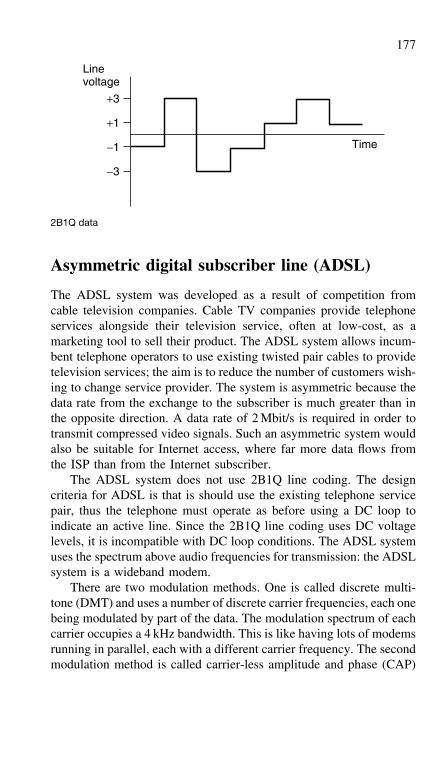
177
Linevoltage
Time
+3
−3
−1
+1
2B1Q data
Asymmetric digital subscriber line (ADSL)
The ADSL system was developed as a result of competition fromcable television companies. Cable TV companies provide telephoneservices alongside their television service, often at low-cost, as amarketing tool to sell their product. The ADSL system allows incum-bent telephone operators to use existing twisted pair cables to providetelevision services; the aim is to reduce the number of customers wish-ing to change service provider. The system is asymmetric because thedata rate from the exchange to the subscriber is much greater than inthe opposite direction. A data rate of 2 Mbit/s is required in order totransmit compressed video signals. Such an asymmetric system wouldalso be suitable for Internet access, where far more data flows fromthe ISP than from the Internet subscriber.
The ADSL system does not use 2B1Q line coding. The designcriteria for ADSL is that is should use the existing telephone servicepair, thus the telephone must operate as before using a DC loop toindicate an active line. Since the 2B1Q line coding uses DC voltagelevels, it is incompatible with DC loop conditions. The ADSL systemuses the spectrum above audio frequencies for transmission: the ADSLsystem is a wideband modem.
There are two modulation methods. One is called discrete multi-tone (DMT) and uses a number of discrete carrier frequencies, each onebeing modulated by part of the data. The modulation spectrum of eachcarrier occupies a 4 kHz bandwidth. This is like having lots of modemsrunning in parallel, each with a different carrier frequency. The secondmodulation method is called carrier-less amplitude and phase (CAP)
178
and is similar to quadrature amplitude modulation (QAM). Insteadof having a carrier that is amplitude and phase modulated, the CAPsystem synthesizes an equivalent waveform.
The disadvantage of using high frequencies for transmission isthat line attenuation increases with frequency. This means that thosesignals which use the higher frequencies are attenuated more thanthose using frequencies just above audio and the working range islimited. The advantage that ADSL has over HDSL is that only a singlepair is required. The disadvantage is that because of line attenuationconsiderations, high level signals are transmitted in the high data ratedirection. To prevent near-end crosstalk problems, the high data ratedirection must always be from the exchange to the customer.
ADSL (G.lite)
A low-cost version of ADSL avoids the need for a filter in the cus-tomer premises to separate the POTS and ADSL signals. It is knownas splitter-less ADSL and is defined by ITU recommendation G.992.2.The line modulation uses DMT and allows a data rate up to 1.5 Mbpsin the downstream direction towards the subscriber and up to 512 kbpsin the upstream direction towards the service provider.
Conventional ADSL using DMT modulation occupies 256 fre-quency bands, each 4 kHz wide. These bands start at 25 kHz andextend up to 1.049 MHz. The alternative G.lite uses 96 frequencybands and therefore its line borne signal has less high frequency con-tent than standard ADSL, with a maximum frequency of 409 kHz.
Single-pair digital subscriber line (SDSL)
Due to the lack of a formal naming convention in the telecommuni-cations industry, the term SDSL has become more generic over timeand to some means any symmetric DSL system. In this section, SDSLis given to be a symmetrical digital subscriber line system developedunder the auspices of ETSI that works over a single pair, at variabledata rates up to 2.3 Mbps. It is intended to carry E1 traffic.
The line modulation is 2B1Q and this is commonly used withMaximum likelihood estimation at the receiver. The 2B1Q signallingsystem transmits one symbol for every two data bits and this is usedby ISDN (sometimes called ISDL, since it is an xDSL technology).However, at the higher data rates employed by SDSL, the pulsesare distorted and determining which symbol was transmitted becomesmore difficult. Maximum likelihood (ML) estimation techniques are
179
used to determine the most likely symbol. Pulse distortion is worseon long subscriber lines, so the maximum line length for SDSL isabout 3 km. At T1 data rates, the maximum line length is about3.4 km, which is why ANSI started to develop their own system calledHDSL2.
ETSI have produced a modified SDSL standard that uses the same16 level PAM line codes as used by the ANSI HDSL2 standard, andwhich has been incorporated into the ITU G.991.2 standard. ETSISDSL systems using 2B1Q line codes will eventually be replaced bySHDSL (G.shdsl or G.991.2) systems.
High-speed digital subscriber line 2 (HDSL2)
Operation of HDSL over a single pair is possible using HDSL2. Thisis intended to carry fixed rate T1 (1.544 Mbps), like HDSL. A 16-level PAM line code is used, with spectral shaping. The symbol ratetransmitted over the line is 517.3 k symbols per second. Each symbolrepresents four bits: three data bits and one forward error correction(FEC) bit. The FEC process uses a single-stage 512-state Trellis-codedmodulation. The power spectral density of the modulated signal is notflat, but uses OPTIS shaping.
HDSL2 is a single-pair, ANSI standard-based replacement forHDSL, which is really only applicable in North America. ANSIHDSL2 will be replaced by SHDSL (G.shdsl or G.991.2).
Single-pair HDSL (G.shdsl–G.991.2)
Standardised by the ITU as G.991.2, SHDSL is intended to providesymmetrical data transmission at rates of up to 2.3 Mbps. Variabledata rates will be possible, from 144 kbps to 2.3 Mbps. Like the ANSIHDSL2 system and the revised ETSI SDSL specification, a 16-levelPAM line code is used. However, the G.hsdsl system does not applyspectral shaping to the signal before it is transmitted: the power spec-tral density is flat. This allows the maximum line length to be 30%greater than 2B1Q SDSL and 20% greater than for HDSL2.
Very-high-speed digital subscriber line (VDSL)
Very high speed digital subscriber line (VDSL) systems are not yetstandardised. The purpose of VDSL is to provide a very high datarate into offices and buildings. The system will be asymmetric, in the
180
early models at least, allowing a maximum upstream rate from thecustomer to the exchange of about 2 Mbit/s. The downstream datarate is expected to be up to 55.2 Mbit/s, which limits the range overtwisted pair cables to about 300 m. Lower data rate systems permit alonger range over twisted pair cable. Limiting the downstream datarate to 27.6 Mbit/s will allow a range of 1 km. Further limiting therate to 13.8 Mbit/s allows a working range of 1.5 km.
Transmission of data to outside the building will use optical fibreas a ‘fibre to the kerb’ (FTTK) system. VDSL will perform the finaldrop into the customer’s premises.
Asynchronous transfer mode
Asynchronous transfer mode
Major standards organisations (such as ISO, ITU and ANSI) haverecognised ATM as the preferred standard for Broadband IntegratedServices Digital Networks (BISDN). Like X.25 and Frame Relay,Asynchronous Transfer Mode (ATM) is a packet-switching technol-ogy. ATM offers considerable promise for the future of broadbanddigital data services. The real benefits of ATM will be realised when-ever video, digital data, and voice services are all integrated on thesame wide area network (ie, the much heralded ‘information super-highway’).
ATM cells
ATM packet cells comprise a total of 53 bytes of which 48 are data(the payload) and 5 are overhead (the header). Depending upon thetype of data being transmitted, the 48 bytes of data may contain addi-tional overhead required to partition and reassemble longer messages.Headers contain Virtual Channel Identifiers (VCI) and Virtual PathIdentifiers (VPI). These are modified, as required, by each node inthe network in order to ensure that the cell reaches its destination.
ATM is an asynchronous protocol in that packets can be receivedat arbitrary intervals of time. Despite this, the ATM bitstream is bothcontinuous and synchronous. This may at first appear to be somethingof an anomaly but you simply need to recall that packets can appearrandomly distributed in time and when packets are not present, otherbits are transmitted to represent the idle state. Thus it is the packetcells that are asynchronous not the bitstream itself.
ATM can operate at any speed and most high-speed network stan-dards can support ATM. Data rates of 51.84 Mbps (OC-1 and STS-1)
181
or 155.52 Mbps (OC-3 and STS-3) are commonly used with the ANSISynchronous Optical Network standard (SONET). Note that ‘OC’refers to the data rate within the optical medium whilst ‘STS’ strictlyrefers to electrical transmission.
ATM and the ISO model for OSI
ATM operates at the Data Link and Physical Layers of the ISO modelfor OSI. Some higher level activities (such as routing) are also pro-vided by ATM. Higher level protocols are added to improve reliabilityand integrity. ATM’s Physical Layer provides the same service as thePhysical Layer in the ISO model but transmits cells rather than indi-vidual bits. The ATM Layer sits above the Physical Layer and isequivalent to the ISO model’s Data Link Layer. The ATM layer isresponsible for reading and interpreting headers and routing informa-tion as well as for packaging the user’s data into 48 byte payloads fortransmission. The ATM Adaptation Layer also accepts the received48 byte payloads and reassembles them into data.
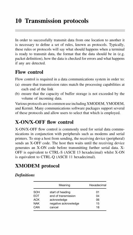
10 Transmission protocols
In order to successfully transmit data from one location to another itis necessary to define a set of rules, known as protocols. Typically,these rules or protocols will say what should happens when a terminalis ready to transmit data, the format that the data should be in (e.g.packet definition), how the data is checked for errors and what happensif any are detected.
Flow controlFlow control is required in a data communications system in order to:(a) ensure that transmission rates match the processing capabilities at
each end of the link(b) ensure that the capacity of buffer storage is not exceeded by the
volume of incoming data.Various protocols are in common use including XMODEM, YMODEM,and Kermit. Many communications software packages support severalof these protocols and allow users to select that which is employed.
X-ON/X-OFF flow controlX-ON/X-OFF flow control is commonly used for serial data commu-nications in conjunction with peripherals such as modems and serialprinters. To stop a host from sending, the receiving device (peripheral)sends an X-OFF code. The host then waits until the receiving devicegenerates an X-ON code before transmitting further serial data. X-OFF is equivalent to CTRL-S (ASCII 13 hexadecimal) whilst X-ONis equivalent to CTRL-Q (ASCII 11 hexadecimal).
XMODEM protocol
Definitions
Meaning Hexadecimal
SOH start of heading 01EOT end of transmission 04ACK acknowledge 06NAK negative acknowledge 15CAN cancel 18
183
Transmission medium level protocol
Asynchronous data transmission with eight data bits, no parity bit, andone stop bit. The protocol imposes no restrictions on the contents ofthe data being transmitted. No control characters are looked for in the128-byte data message blocks. Data may be transmitted in any form(binary, ASCII, etc.). The protocol may be used in a 7-bit environmentfor the transmission of ASCII-encoded data.
To maintain compatibility with CP/M file structure and henceallow ASCII files to be transferred to and from CP/M systems, thefollowing recommendations have been made:
(a) ASCII tab characters (09 hexadecimal) should be set every eightcharacter positions
(b) lines should be terminated by a CR-LF combination (0D hexadec-imal followed by 0A hexadecimal)
(c) end-of-file should be indicated by CTRL-Z (1A hexadecimal)(d) variable length data is divided into 128-byte blocks for transmis-
sion purposes(e) if the data ends on a 128-byte boundary (ie, a CR-LF combination
occurs in the 127th and 128th byte positions of a block) a sub-sequent block containing CTRL-Z should preferably be appendedin order to indicate the end-of-file (EOF)
(f) the last block transmitted is not shortened (ie, all blocks have alength of 128 bytes – there is no short block ).
Character
File level protocol
The XMODEM file level protocol involves the following considera-tions:
(a) all errors are retried ten times(b) some versions of the protocol use CAN (CTRL-X) to abort trans-
mission. Unfortunately, such a scheme can result in prematuretermination of a transmission due to corruption of data bytes(which may be falsely read as CAN)
(c) the receiver will timeout after ten seconds and then send a NAKcharacter. The timeout sequence should be repeated every tenseconds until the transmitter is ready to resume the transmissionof data. When receiving a block, the time out is reduced to onesecond for each character.
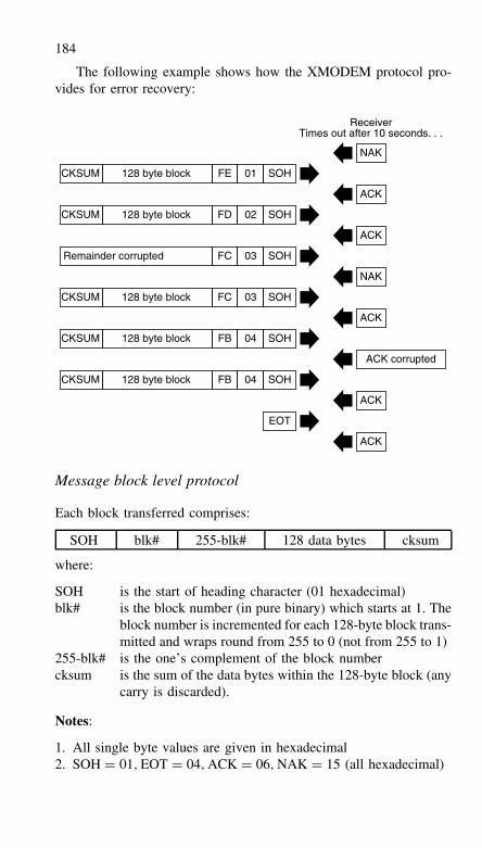
184
The following example shows how the XMODEM protocol pro-vides for error recovery:
128 byte blockCKSUM FE 01 SOH
128 byte blockCKSUM FD 02 SOH
Remainder corrupted FC 03 SOH
128 byte blockCKSUM FC 03 SOH
128 byte blockCKSUM FB 04 SOH
128 byte blockCKSUM FB 04 SOH
EOT
ACK
ACK
ACK corrupted
ACK
NAK
ACK
ACK
NAK
ReceiverTimes out after 10 seconds. . .
Message block level protocol
Each block transferred comprises:
SOH blk# 255-blk# 128 data bytes cksum
where:
SOH is the start of heading character (01 hexadecimal)blk# is the block number (in pure binary) which starts at 1. The
block number is incremented for each 128-byte block trans-mitted and wraps round from 255 to 0 (not from 255 to 1)
255-blk# is the one’s complement of the block numbercksum is the sum of the data bytes within the 128-byte block (any
carry is discarded).
Notes:
1. All single byte values are given in hexadecimal2. SOH = 01, EOT = 04, ACK = 06, NAK = 15 (all hexadecimal)
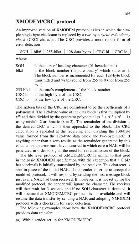
185
XMODEM/CRC protocol
An improved version of XMODEM protocol exists in which the sim-ple single byte checksum is replaced by a two-byte cyclic redundancycheck (CRC) character. The CRC provides a more robust form oferror detection
SOH blk# 255-blk# 128 data bytes CRC hi CRC lo
where:
SOH is the start of heading character (01 hexadecimal)blk# is the block number (in pure binary) which starts at 1.
The block number is incremented for each 128-byte blocktransmitted and wraps round from 255 to 0 (not from 255to 1)
255-blk# is the one’s complement of the block numberCRC hi is the high byte of the CRCCRC lo is the low byte of the CRC.
The sixteen bits of the CRC are considered to be the coefficients of apolynomial. The 128-byte value of the data block is first multiplied byx16 and then divided by the generator polynomial (x16 + x12 + x5 + 1)
using modulo-2 arithmetic (x = 2). The remainder of the division isthe desired CRC which is then appended to the block. The CRCcalculation is repeated at the receiving end, dividing the 130-bytevalue formed from the 128-byte data block and two-byte CRC. Ifanything other than a zero results as the remainder generated by thiscalculation, an error must have occurred in which case a NAK will begenerated in order to signal the need for retransmission of the block.
The file level protocol of XMODEM/CRC is similar to that usedin the basic XMODEM specification with the exception that a C (43hexadecimal) is initially transmitted by the receiver. This character issent in place of the initial NAK. If the sender is set up to accept themodified protocol, it will respond by sending the first message blockjust as if a NAK had been received. If, however, it is not set up for themodified protocol, the sender will ignore the character. The receiverwill then wait for 3 seconds and if no SOH character is detected, itwill assume that XMODEM/CRC protocol is not available and willresume the data transfer by sending a NAK and adopting XMODEMprotocol with a checksum for error detection.
The following examples show how the XMODEM/CRC protocolprovides data transfer:
(a) With a sender set up for XMODEM/CRC
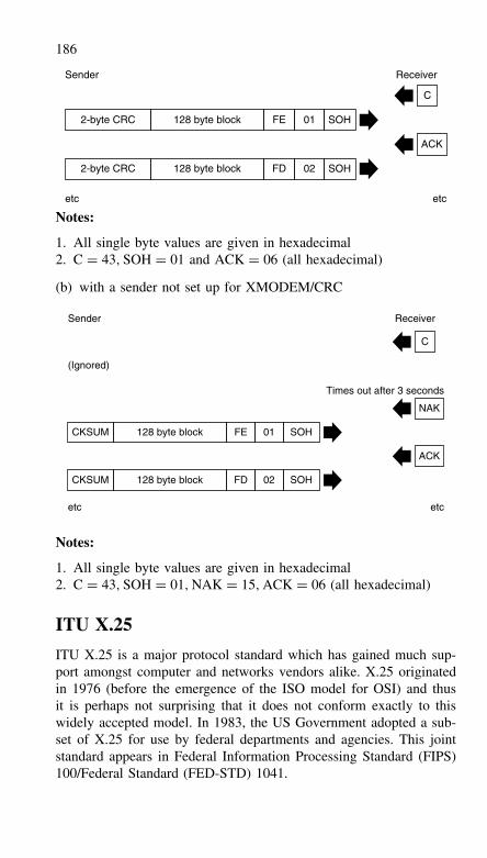
186
128 byte block2-byte CRC FE 01 SOH
128 byte block2-byte CRC FD 02 SOH
ACK
C
Receiver
etc etc
Sender
Notes:
1. All single byte values are given in hexadecimal2. C = 43, SOH = 01 and ACK = 06 (all hexadecimal)
(b) with a sender not set up for XMODEM/CRC
128 byte blockCKSUM FE 01 SOH
128 byte blockCKSUM FD 02 SOH
ACK
NAK
C
etc etc
Times out after 3 seconds
ReceiverSender
(Ignored)
Notes:
1. All single byte values are given in hexadecimal2. C = 43, SOH = 01, NAK = 15, ACK = 06 (all hexadecimal)
ITU X.25
ITU X.25 is a major protocol standard which has gained much sup-port amongst computer and networks vendors alike. X.25 originatedin 1976 (before the emergence of the ISO model for OSI) and thusit is perhaps not surprising that it does not conform exactly to thiswidely accepted model. In 1983, the US Government adopted a sub-set of X.25 for use by federal departments and agencies. This jointstandard appears in Federal Information Processing Standard (FIPS)100/Federal Standard (FED-STD) 1041.
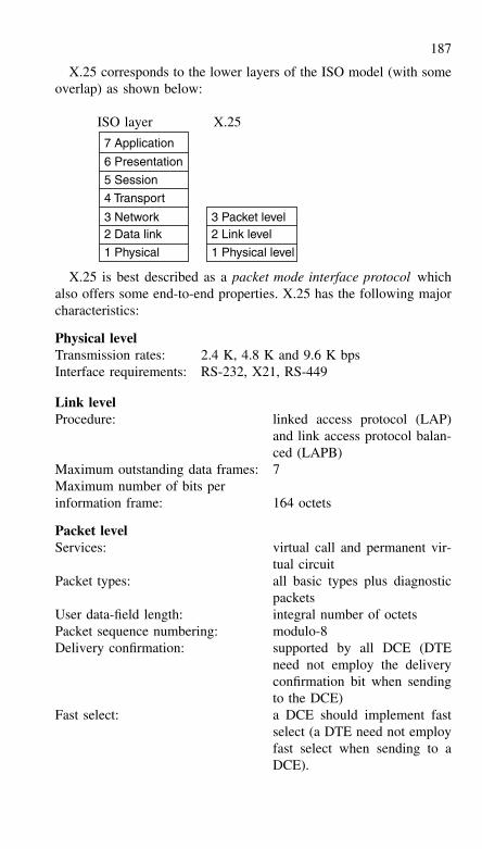
187
X.25 corresponds to the lower layers of the ISO model (with someoverlap) as shown below:
ISO layer X.25
7 Application
6 Presentation
5 Session
4 Transport
3 Network2 Data link
1 Physical
3 Packet level2 Link level
1 Physical level
X.25 is best described as a packet mode interface protocol whichalso offers some end-to-end properties. X.25 has the following majorcharacteristics:
Physical levelTransmission rates: 2.4 K, 4.8 K and 9.6 K bpsInterface requirements: RS-232, X21, RS-449
Link levelProcedure: linked access protocol (LAP)
and link access protocol balan-ced (LAPB)
Maximum outstanding data frames: 7Maximum number of bits perinformation frame: 164 octets
Packet levelServices: virtual call and permanent vir-
tual circuitPacket types: all basic types plus diagnostic
packetsUser data-field length: integral number of octetsPacket sequence numbering: modulo-8Delivery confirmation: supported by all DCE (DTE
need not employ the deliveryconfirmation bit when sendingto the DCE)
Fast select: a DCE should implement fastselect (a DTE need not employfast select when sending to aDCE).
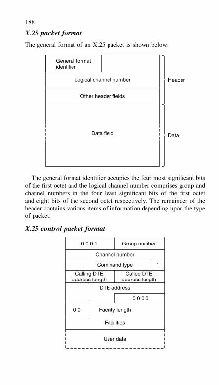
188
X.25 packet format
The general format of an X.25 packet is shown below:
Logical channel number
Other header fields
General formatidentifier
Data field Data
Header
The general format identifier occupies the four most significant bitsof the first octet and the logical channel number comprises group andchannel numbers in the four least significant bits of the first octetand eight bits of the second octet respectively. The remainder of theheader contains various items of information depending upon the typeof packet.
X.25 control packet format
0 0
Calling DTEaddress length
DTE address
Called DTEaddress length
Facility length
Facilities
User data
0 0 0 0
0 0 0 1 Group number
Channel number
1Command type
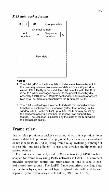
189
X.25 data packet format
User data
Q D 01 Group number
Channel number
OAck.number
SequencenumberM
Notes:1. The Q bit (MSB of the first octet) provides a mechanism by which
the user may operate two streams of data across a single virtualcircuit. If this facility is not used, the Q bit defaults to 0. The Q bitis set to 1 when messages are sent to the packet assembly/dis-assembly (PAD) device. Packets destined for a terminal (or assem-bled by a PAD from a terminal) have the Q bit reset (ie, 0).
2. The D bit is set to logic 1 in order to indicate that immediate con-firmation of packet receipt is required (rather than waiting until awindow is full). In the call set-up routine, the D bit may be set bythe sender to ascertain whether the receiver can support thisfeature. The response is indicated by the state of the D bit withinthe call accept packet.
Frame relayFrame relay provides a packet switching network is a physical layerusing a data link protocol. The physical layer is often narrow-bandor broadband ISDN (ATM) using frame relay switching, although itis possible (but less efficient) to use time division multiplexers andpacket switches.
The link access protocol, used by X.25 networks (LAPB) has beenadapted for frame relay using ISDN networks as LAPD. This protocolprovides congestion control and error detection, and is used to con-trol closed user groups. The LAPD frame comprises: one flag byte,two address bytes, one control byte, payload data, followed by twoseparate cyclic redundancy check bytes (CRC1 and CRC2).
190
As a packet traverses a frame relay network, error checking iscarried out at the frame relay switch, using the CRC bytes at the endof the LAPD packet. If an error is found, the packet is discarded. Itis up to higher protocols to request retransmission of any packets thathave not been received, and this is carried out at the end receivingstation (not at the switch). Requests for retransmission are not carriedout at the switch because this would reduce the switching speed –sinceATM is very reliable the number of retransmission requests is low.
High-level data link controlHigh-level data link control (HDLC) is a synchronous communicationprotocol on which many of today’s LAN protocols are based. HDLCis a bit-oriented protocol ; the bit representation of the data in theform of characters, binary numbers, or decimal numbers, is containedwholly within the data field of a single frame.
HDLC provides three classes of procedure for network connectionbetween adjacent nodes in a point-to-point communication system.
Asynchronous balanced mode
Asynchronous balanced mode (ABM) relates to full duplex commu-nication between two nodes who are considered to be ‘equal partners’in the data exchange. Both can initiate and terminate a connectionand both can send data (without prior interrogation) on an establishedconnection.
Normal response mode
Normal response mode (NRM) relates to communication between acontrol device (eg, a computer) and a number of secondary stations.
Asynchronous response mode
Asynchronous response mode (ARM) relates to communication inhalf-duplex mode between a primary station which sends out com-mands and data and a secondary station which returns responses.
HDLC frame structureA number of fields are employed within an HDLC frame, including:
Flag
The flag is used for synchronisation and also indicates the start (pream-ble) and end (postamble) of the frame. The flag takes the form:
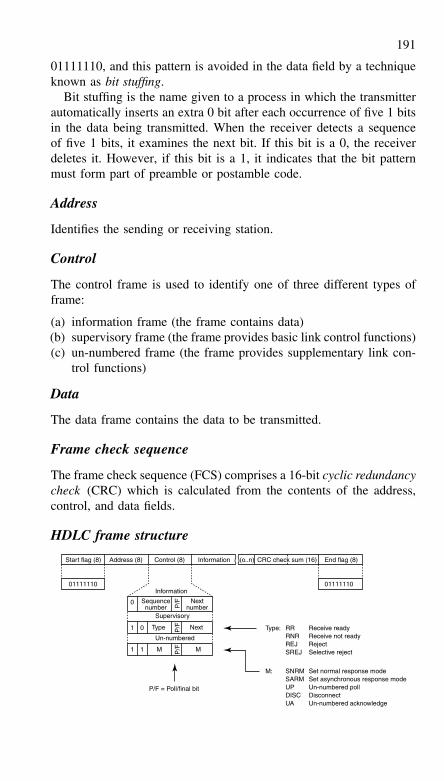
191
01111110, and this pattern is avoided in the data field by a techniqueknown as bit stuffing.
Bit stuffing is the name given to a process in which the transmitterautomatically inserts an extra 0 bit after each occurrence of five 1 bitsin the data being transmitted. When the receiver detects a sequenceof five 1 bits, it examines the next bit. If this bit is a 0, the receiverdeletes it. However, if this bit is a 1, it indicates that the bit patternmust form part of preamble or postamble code.
Address
Identifies the sending or receiving station.
Control
The control frame is used to identify one of three different types offrame:
(a) information frame (the frame contains data)(b) supervisory frame (the frame provides basic link control functions)(c) un-numbered frame (the frame provides supplementary link con-
trol functions)
Data
The data frame contains the data to be transmitted.
Frame check sequence
The frame check sequence (FCS) comprises a 16-bit cyclic redundancycheck (CRC) which is calculated from the contents of the address,control, and data fields.
HDLC frame structure
Start flag (8) Address (8) Control (8) Information (o..n) CRC check sum (16) End flag (8)
0111111001111110Information
Supervisory
Un-numbered
0
1 0
1 1 M M
Sequencenumber
Type Next
NextnumberP
/FP
/FP
/F
P/F = Poll/final bit
Type: RRRNRREJSREJ
Receive readyReceive not readyRejectSelective reject
M: SNRMSARMUPDISCUA
Set normal response modeSet asynchronous response modeUn-numbered pollDisconnectUn-numbered acknowledge
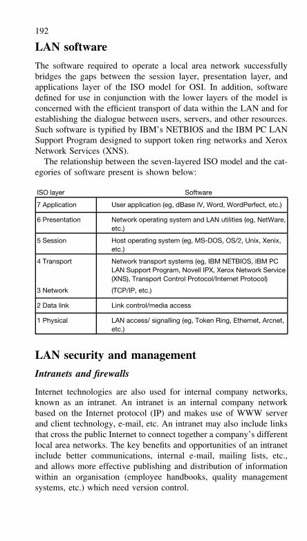
192
LAN software
The software required to operate a local area network successfullybridges the gaps between the session layer, presentation layer, andapplications layer of the ISO model for OSI. In addition, softwaredefined for use in conjunction with the lower layers of the model isconcerned with the efficient transport of data within the LAN and forestablishing the dialogue between users, servers, and other resources.Such software is typified by IBM’s NETBIOS and the IBM PC LANSupport Program designed to support token ring networks and XeroxNetwork Services (XNS).
The relationship between the seven-layered ISO model and the cat-egories of software present is shown below:
ISO layer Software
7 Application User application (eg, dBase IV, Word, WordPerfect, etc.)
6 Presentation Network operating system and LAN utilities (eg, NetWare,etc.)
5 Session Host operating system (eg, MS-DOS, OS/2, Unix, Xenix,etc.)
4 Transport Network transport systems (eg, IBM NETBIOS, IBM PCLAN Support Program, Novell IPX, Xerox Network Service(XNS), Transport Control Protocol/Internet Protocol)
3 Network (TCP/IP, etc.)
2 Data link Link control/media access
1 Physical LAN access/ signalling (eg, Token Ring, Ethernet, Arcnet,etc.)
LAN security and management
Intranets and firewalls
Internet technologies are also used for internal company networks,known as an intranet. An intranet is an internal company networkbased on the Internet protocol (IP) and makes use of WWW serverand client technology, e-mail, etc. An intranet may also include linksthat cross the public Internet to connect together a company’s differentlocal area networks. The key benefits and opportunities of an intranetinclude better communications, internal e-mail, mailing lists, etc.,and allows more effective publishing and distribution of informationwithin an organisation (employee handbooks, quality managementsystems, etc.) which need version control.
193
Connection between the intranet and the Internet has security risks,including access by hackers or competitors to commercial information.Encryption can be used to make e-mail secure and restricting accessto information can be achieved by installing a ‘firewall’ between theinternal network and the Internet.
Firewalls are installed at the network interface (usually on a router)and are either packet screens or proxy servers. Packet screens examineeach packet passing to and from the internal network. Packets areeither allowed through or discarded depending on the rules applied tothe firewall. Proxy servers control the type of services that may passthrough the firewall, for example WWW or e-mail. Proxy servers arevery generally secure.
Virtual private networks (VPNs)
Confidence in the security of IP networks is increasing and Intranetsare now being provided on a shared IP infrastructure, on what isreferred to as a virtual private network (VPN). Potentially, thousandsof VPNs can be provided over a single shared high-capacity global IPnetwork. VPNs can also support extranets, in which secure connec-tivity is extended to suppliers, customers or communities of interestover a common IP infrastructure.
Electronic commerce
Many companies now have on-line shops through which goods canbe ordered. Travel, banking and insurance companies have been par-ticularly active, but security is an issue. Cryptography provides thesecurity necessary for privacy of communications and payments tobe made over the Internet. Two forms of encryption are in commonuse: symmetric encryption and asymmetric encryption (also knownas public-key cryptography). Both use cryptographic algorithms andkeys to encode and decode data. The keys are parameters used in themathematical encryption process.
In symmetric key systems, the sender and receiver must use identi-cal keys. The security of symmetric key systems depends on keepingthe key information private, therefore the key must be sent over aseparate and secure path. This is a disadvantage for widespread usein electronic commerce. Symmetric encryption algorithms are muchfaster than public-key algorithms and the Digital Encryption Standard(DES) is widely used for this.
Public-key schemes use pairs of related keys. Each user has a pri-vate key, which is kept secret, and a public key, which is published

194
and readily available to others. Encryption of a message with therecipient’s public key provides confidentiality because the owner ofthe corresponding private key is the only person who can read it. Thisapproach is often used as a secure way of exchanging symmetric keys.Encryption of a message with the sender’s private key also providesa signature since the message can only be decrypted correctly usingthe sender’s public key.
The overall security of key-based systems depends on the strengthof the cryptographic algorithms and on the security of the keys. Thestrength of the encryption increases exponentially with key length.
Network computing
In network computing all software and data is stored remotely onservers in the network and downloaded to the user’s PC as and whenrequired. The main advantages of network computing are reduced ver-sion management, and rapid access to new applications and services.
Java
The basis of network computing is the Java programming language.The software required to execute Java is available within every WWWbrowser, which means that almost every networked computer is capableof running a Java program. Java offers animation and the full power ofa computer programming language in the browser. Java applicationscan expect to be seen running independently of the browser.
Real-time services
Limits in processing speed and Internet bandwidth have restricted thedevelopment of real-time services. But recent developments in PCtechnology have enabled video compression within a realistic period.Competition in telecommunications has created considerable Internetbandwidth. The high speed processors and wide bandwidth have ledto a rapid increase in the speed of real-time services development overthe Internet, including Internet telephones, audio and video streamingapplications.
The prospect of ‘free’ calls using Internet telephony has excitedsome enthusiasts, but the truth is the fundamental costs of Internettelephony and PSTN telephony are similar. However Internet tele-phony has yet to match the convenience, ease of use, call quality
195
and customer service of the PSTN. However, Internet telephony iseasily integrated with other computer applications and so is likely tocontinue to be used and to develop. A gateway is needed to providePSTN interconnectivity for telephone calls between IP networks andthe PSTN.
Voice over IP is offered on a ‘best effort’ basis and the qualityof the call is dependent upon network congestion. Factors that affectcall quality are packet loss and wide variations in network delay. TheIETF is developing the integrated services architecture (ISA), whichis a framework that aims to offer control over the quality of serviceprovided by a network. ISA allows applications to prioritise theirtraffic and to request network resources to enable the priority systemto work. Two major components of ISA are IP multicast and resourcereservation protocol (RSVP).
The quality of service seen by the user depends on the qualityof service provided by the network, the operating systems and theapplication protocols. The requirement for a reliable signal conflictswith the requirement for low delay. Retransmission of a packet foundto contain errors will lead to increased end-to-end delay and increasedjitter (variation in end-to-end delay).
The enhancement of the Internet and intranets to support real-timeservices is exciting, because it promises a future in which a single net-work can be used for voice, data and all other media. It also promisesexcellent computer/ telephony integration (CTI) and interactive enter-tainment.
Differentiated services
One approach to providing quality of service (QoS) in core IPnetworks is based on the IETF standard of differentiated services(Diffserv). Diffserv gives high priority to certain types of data; forexample, gold service for delay-sensitive voice or video traffic, silverfor medium-priority services such as e-mail, and bronze for low-priority data. Priorities can be identified in several ways, includingthe type of service bits in the IP packet header. One technique forgiving different levels of priority is weighted random early discard(WRED), which selectively discards low priority packets at the edgeof the network to protect the core from congestion. Another techniqueis class-based queuing (CBQ), in which bandwidth and delay limitsare set. Packets are then processed through the router according totheir class or priority.
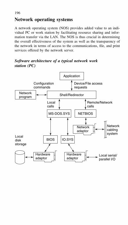
196
Network operating systems
A network operating system (NOS) provides added value to an indi-vidual PC or work station by facilitating resource sharing and infor-mation transfer via the LAN. The NOS is thus crucial in determiningthe overall effectiveness of the system as well as the transparency ofthe network in terms of access to the communications, file, and printservices offered by the network server.
Software architecture of a typical network workstation (PC)
Localdiskstorage
Localcalls
Configurationcommands
Device/File accessrequests
Remote/Networkcalls
Local serial/parallel I/O
Networkcablingsystem
Shell/Redirector
Application
MS-DOS.SYS
BIOS IO.SYS
NETBIOS
Networkprogram
Networkadaptor
Hardwareadaptor
Hardwareadaptor
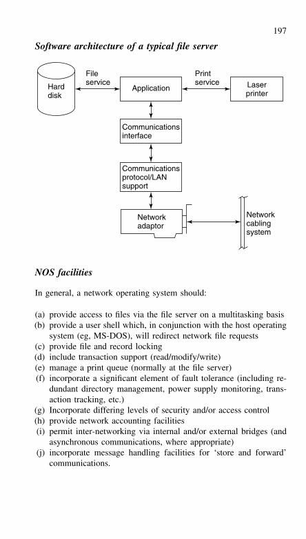
197
Software architecture of a typical file server
Application
Networkcablingsystem
Printservice
FileserviceHard
disk
Communicationsinterface
Networkadaptor
Communicationsprotocol/LANsupport
Laserprinter
NOS facilities
In general, a network operating system should:
(a) provide access to files via the file server on a multitasking basis(b) provide a user shell which, in conjunction with the host operating
system (eg, MS-DOS), will redirect network file requests(c) provide file and record locking(d) include transaction support (read/modify/write)(e) manage a print queue (normally at the file server)(f) incorporate a significant element of fault tolerance (including re-
dundant directory management, power supply monitoring, trans-action tracking, etc.)
(g) Incorporate differing levels of security and/or access control(h) provide network accounting facilities(i) permit inter-networking via internal and/or external bridges (and
asynchronous communications, where appropriate)(j) incorporate message handling facilities for ‘store and forward’
communications.
198
Network protocols
SPX/IPX
Novell was the first vendor to introduce a network operating system(NOS) that would support true file-sharing. NetWare is the name ofNovell’s suite of network utilities that allows any PC platform to sharefiles, CD-ROM drives, and printers across a LAN. The suite workswith almost any popular LAN standard including Ethernet, TokenRing, and ARCnet.
Novell’s SPX (Sequenced Packet Exchange) and IPX (InternetPacket Exchange), respectively, provide the Transport Layer andNetwork Layer of the ISO model for OSI. SPX/IPX is not a singleprotocol but a suite of standard procedures for connecting computers.IPX is responsible for addressing packets between NetWare nodeswhile SPX encapsulates IPX packets for reliable data transfer. Manyapplications, however, are able to monitor the reliability of datatransfer themselves and they make use of IPX alone, thus reducingoverhead and improving efficiency.
IPX is fast and efficient with the relatively small packets (eg, 512bytes) found in a PC networking environment under DOS or Win-dows. In the context of wide area networks (WAN), small packets areinefficient due to the appreciable overhead that can be present whena large amount of data is to be transferred. Packet burst mode (firstintroduced in Net Ware 3.x) allows the 512 byte packet length to beexceeded. IPX packets of up to 64 kbyte can be supported in thismode. Burst mode can greatly improve the efficiency of an expen-sive long-distance low-speed circuit. The improvement becomes evenmore significant when large files are to be exchanged.
Internet protocol (IP)
The foundation of the Internet is the internet protocol (IP), whichroutes data packets across the network from one computer to another.IP is very simple because it focuses specifically on packet routing butdoes not guarantee packet delivery. Packets may be lost or corrupted,and a sequence of packets sent between two hosts may take differentroutes and may arrive in a different order. These issues are left forother protocols to handle.
IP packets are sent from one router to another towards their des-tination. Each router maintains routing tables, which determine theoutput interface on which a packet should be sent. When a packet
199
arrives at a router, it is stored in a queue. When it reaches the front ofthe queue, the router reads the destination address in the header. Thisaddress is looked up in the routing table and then the router transmitsthe packet out of the appropriate interface port. Routing tables areregularly updated to take account of network failures or changes tothe configuration of the network.
If the network is congested, the input queues at routers can becomevery long, which increases the packet transit delay. Under heavy con-gestion the queues may become full and packets are discarded. It isup to other protocols (such as TCP) to recognise a missing packet andto request retransmission.
The military origin of IP has helped it to become the de facto inter-networking standard. The lack of delivery-guarantee makes it simpleand efficient, because not all applications require these guarantees.Also, its ability to adapt to network failures and configuration changeshas made IP particularly robust. Its ability to adapt has enabled it tocope with the exponential Internet growth and allows networks ofmany sizes and type to be easily connected.
IPv4
Currently, all IP networks use Version 4 of the Internet protocol. Thiswas developed before it was realised how popular IP would become.The greatest limitation of IP version 4 (IPv4) is the size of the addressspace, which allows only a 32-bit address. This is not enough foreveryone to be allocated a unique address. Hence IP addresses havebecome scarce and schemes have had to be developed to enable suffi-cient addresses. One technique is network address translation (NAT),which translates and isolates the Internet address so that previouslyused addresses can be re-used on the internal network side of therouter.
The Internet Engineering Task Force (IETF) has been workingto design the next generation of IP, IPv6 (the proposed IPv5 wasrejected). A global experimental network has been built, called the6bone, with the aim of evaluating early IPv6 implementations andidentifying any problems. The IPv4 header contains 10 fields, achecksum, two addresses and some options, see diagram below. IPv4addresses are based on a 32-bit word that, in theory, gives IPv4 over4 billion addresses. The options field in the IP header is a disadvantagebecause it requires recalculation of a checksum for every possible IPv4header type.
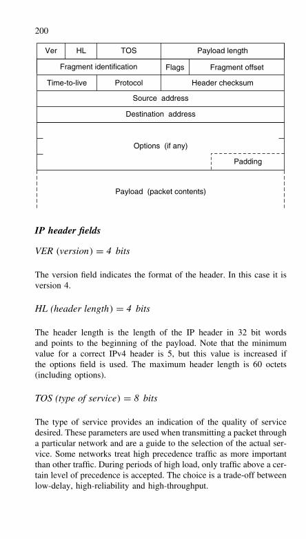
200
Ver HL TOS
Source address
Destination address
Payload (packet contents)
Options (if any)
Payload length
Fragment identification Flags Fragment offset
Time-to-live Protocol Header checksum
Padding
IP header fields
VER (version) = 4 bits
The version field indicates the format of the header. In this case it isversion 4.
HL (header length) = 4 bits
The header length is the length of the IP header in 32 bit wordsand points to the beginning of the payload. Note that the minimumvalue for a correct IPv4 header is 5, but this value is increased ifthe options field is used. The maximum header length is 60 octets(including options).
TOS (type of service) = 8 bits
The type of service provides an indication of the quality of servicedesired. These parameters are used when transmitting a packet througha particular network and are a guide to the selection of the actual ser-vice. Some networks treat high precedence traffic as more importantthan other traffic. During periods of high load, only traffic above a cer-tain level of precedence is accepted. The choice is a trade-off betweenlow-delay, high-reliability and high-throughput.
201
Bits 0–2 determine the precedence, given by the following values:
111 – Network Control110 – Inter-network Control101 – CRITIC/ECP100 – Flash Override011 – Flash010 – Immediate001 – Priority000 – Routine
Bit 3 determines the delay (0 = normal delay, 1 = low delay). Bit 4determines the throughput (0 = normal, 1 = high) Bit 5 determinesthe reliability (0 = normal, 1 = high) and Bits 6–7 are reserved forfuture use.
Total length = 16 bits
Total length is the length of the packet, measured in octets, includingthe header and payload. This field allows the length of a packet to beup to 65,535 octets. Such long packets are impractical for most hostsand networks; Ethernet based networks limit packets to 1500 octets.
All hosts must be prepared to accept packets of up to 576 octets(whether they arrive whole or in fragments). It is recommended thathosts only send packets larger than 576 octets if they have checkedthat the destination is prepared to accept them. The number 576 isselected to allow a reasonable sized data block to be transmitted inaddition to the required header information. For example, this sizeallows a data block of 512 octets plus 64 header octets to fit in apacket. The maximal IP header is 60 octets, but is typically 20 octets,thus allowing a margin for headers of higher level protocols.
Fragment identification = 16 bits
An identifying value assigned by the sender to aid in assembling thefragments of a packet.
Flags = 3 bits
Various control flags. Bit 0 is reserved and must have a value of zero.Bit 1 (DF) (0 = Fragmentation allowed, 1 = do not fragment). Bit 2(MF) (0 = last fragment, 1 = more fragments).
202
Fragment offset = 13 bits
This field indicates where in the packet this fragment belongs. Thefragment offset is measured in units of 8 octets (64 bits). The firstfragment has offset zero.
Time-to-live = 8 bits
This field indicates the maximum time the packet is allowed to remainwithin the Internet. If this field contains the value zero, then the packetmust be destroyed. The value in this field is reduced by at least oneduring IP header processing by a router. The ‘time-to-live’ is measuredin units of seconds, but if the router process the packet in less thanone second the T-T-L will be shorter than expected. In fact, the T-T-Lmust be thought of as an upper limit on the time a packet may exist.The aim is to discard undeliverable packets.
Protocol = 8 bits
This field indicates the next higher level protocol used in the payloadportion of the IP packet. The values for various protocols are specifiedin ‘Assigned Numbers’, and examples are: 06 (hex) = TCP, 11(hex) = UDP and 58 (hex) = IGRP (Cisco proprietary).
Header checksum = 16 bits
This is a checksum on the header only. Since some header fieldschange (e.g., time-to-live), this is computed and verified at each pointthat the IP header is processed.
The header is broken down into 16-bit words, which are thensummed using one’s complement arithmetic with any carry addedin. A one’s complement of the result gives the checksum. For thepurpose of this computation, zero value is used for the checksumfield. This checksum is simple to compute and has been found to beadequate.
Source address = 32 bits
The source address.
Destination address = 32 bits
The destination address.
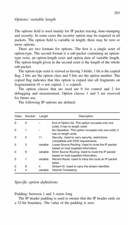
203
Options: variable length
The options field is used mainly for IP packet tracing, time-stampingand security. In some cases the security option may be required in allpackets. The option field is variable in length; there may be zero ormore options.
There are two formats for options. The first is a single octet ofoption-type. The second format is a sub-packet containing an option-type octet, an option-length octet and option data of variable length.The option-length given in the second octet is the length of the wholesub-packet.
The option-type octet is viewed as having 3 fields: 1 bit is the copiedflag, 2 bits are the option class and 5 bits are the option number. Thecopied flag indicates that this option is copied into all fragments onfragmentation (0 = not copied, 1 = copied).
The option classes that are used are 0 for control and 2 fordebugging and measurement. Option classes 1 and 3 are reservedfor future use.
The following IP options are defined:
Class Number Length Description
0 0 – End of Option list. This option occupies only oneoctet; it has no length octet.
0 1 – No Operation. This option occupies only one octet; ithas no length octet.
0 2 11 Security. Used to carry security, restrictionscompatible with DOD requirements.
0 3 variable Loose Source Routing. Used to route the IP packetbased on host supplied information.
0 9 variable Strict Source Routing. Used to route the IP packetbased on host supplied information.
0 7 variable Record Route. Used to trace the route an IP packettakes.
0 8 4 Stream ID. Used to carry the stream identifier.2 4 variable Internet Timestamp.
Specific option definitions
Padding: between 1 and 3 octets longThe IP header padding is used to ensure that the IP header ends on
a 32-bit boundary. The value of the padding is zero.
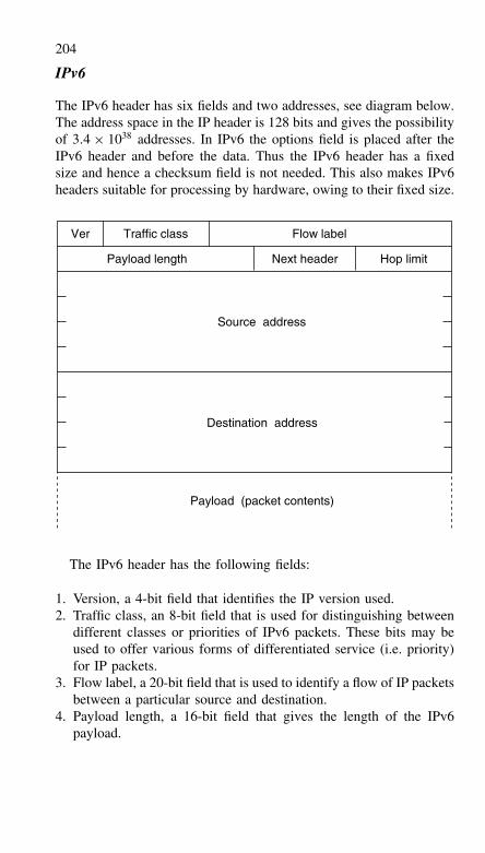
204
IPv6
The IPv6 header has six fields and two addresses, see diagram below.The address space in the IP header is 128 bits and gives the possibilityof 3.4 × 1038 addresses. In IPv6 the options field is placed after theIPv6 header and before the data. Thus the IPv6 header has a fixedsize and hence a checksum field is not needed. This also makes IPv6headers suitable for processing by hardware, owing to their fixed size.
Payload (packet contents)
Destination address
Source address
Payload length
Traffic classVer Flow label
Next header Hop limit
The IPv6 header has the following fields:
1. Version, a 4-bit field that identifies the IP version used.2. Traffic class, an 8-bit field that is used for distinguishing between
different classes or priorities of IPv6 packets. These bits may beused to offer various forms of differentiated service (i.e. priority)for IP packets.
3. Flow label, a 20-bit field that is used to identify a flow of IP packetsbetween a particular source and destination.
4. Payload length, a 16-bit field that gives the length of the IPv6payload.
205
5. Next header, an 8-bit field that identifies the type of header imme-diately following the IPv6 header, for example, UDP or TCP. Thisis the same as used in IPv4.
6. Hop limit, an 8-bit field whose decimal value is decreased by oneeach time the packet passes through a router. The IP packet isdiscarded if this value reaches zero.
7. Source address, a 128-bit field that represents the source addressof the IPv6 packet.
8. Destination address, a 128-bit field that represents the destinationaddress of the IPv6 packet.
Each IPv6 address is represented by eight groups of 16-bit numbers,separated by colons. Each number is displayed as four hexadecimalfigures. An example of an IPv6 address is 16EE:3B40:0000:0000:000C:03E9:7ADE:9BB7. Where there are zeroes in a hexadecimalblock, a double-colon can replace them. Thus the same IPv6 addresscan be represented as: 16EE:3B40::C:3E9:7ADE:9BB7.
IPv6 has been designed to support ‘real-time’ traffic, such as voiceand video. It does this using the traffic class field and the flow labelfield, and these are used to minimise the delay and delay variation ofthe IP packets. The traffic class field is assigned different values (1to 8) dependent upon the type of IP data, typically video could beassigned a low value and e-mail a high value, the lower values givinggreater priority. The flow label field is used to identify a stream ofIPv6 packets that each have a particular destination address and aparticular source address. A router will be able to identify packetsfrom their flow label and simply forward them without having to readthe address fields.
It is probable that an IPv6 Internet will be operated in parallel withthe existing IPv4 Internet. Host computers will contain both the IPv4and IPv6 stack, and applications using the Internet will determine theIP protocol version from information provided by the domain nameservice (DNS).
Transport protocols
Transport protocols are used together with IP in order to provide errorchecking, error correction or recovery. The transport frame (includingdata and transport header) is placed inside the Internet packet andforms the data part of an IP packet.
206
There are two main transport protocols in use on the Internet – UDPand TCP. User packet protocol (UDP) is intended for sendingmessages without guarantee of arrival and without notifying the senderof successful or failed delivery. It is very simple. In addition tothe data carried within the packet, information is supplied about theapplication being used and a checksum is transmitted to indicatewhether any data has been corrupted in transit. In contrast to UDP,the TCP protocol is designed to handle all types of network failure.If packets are lost or corrupted then TCP arranges for them to bere-transmitted. If packets arrive out of order then TCP will re-orderthem. If packets are repeatedly lost, the TCP source will assume thatthe network is congested and reduce its transmission rate.
Ports
At any one time, a terminal connected to an IP network may be inter-acting with other hosts and a number of different applications maybe involved. Port numbers are used to identify for which applica-tion and for which activity a packet is intended. Each UDP or TCPpacket carries two port numbers; one port number identifies the serverapplication and the other port number is selected by the client to dis-tinguish the particular activity. Commonly used ports, which are usedwith applications like Telnet and FTP, are defined in the assignednumbers RFC. An RFC is a request for comments and is part of thestandardisation process used by the IETF.
Telnet
Telnet is a very basic Internet function that allows a user to access aserver remotely. This is known as remote terminal access and worksby carrying ASCII text (typed by the user) to the remote server andthen returning the output from the application on the remote server tothe user.
File transfer protocol (FTP)
FTP provides a basic service for the reliable transfer of files from onemachine to another and allows the user to establish a control connec-tion between their client and the server. This connection can be usedto navigate through the server’s directory structure and request the
207
transmission of files. A separate data connection is set up to transmitthe files.
Domain name service (DNS)
The domain name service provides name/address translation for allobjects on the Internet. Every computer (and every router) on theInternet has an individual name written by concatenating two or morenames using ‘.’ as a separator, e.g. ieee.org. In this name the top leveldomain is ‘org’ and the IEEE owns the sub-domain (or name-space)‘ieee’.
The owner of a ‘name space’ must run a DNS server, which presentsits address to the DNS server at the next level up. Applications such asFTP, SMTP, Telnet and WWW send a request to the local DNS server,which responds by producing the answer itself or with the address ofa DNS server that can provide the answer. If the local DNS serverresponds with the answer, then this may have come either from itsown look-up tables or from another DNS server (that it approachedon the application’s behalf).
Electronic mail or e-mail is the electronic equivalent of the traditionalpostal service. E-mail is sent from a mail ‘client’ (a program whichruns on the user’s machine) to the destination mailbox using the sim-ple mail transfer protocol (SMTP). Other protocols such as POP3 orIMAP4 are used for checking and retrieving mail from a mailbox.SMTP routes emails from the mail agent to the destination mailboxvia a number of mail handlers. Mail handlers behave like conventionalsorting offices; that is, they sort the mail and pass it on to the nextmail handler.
An SMTP mail address is based on an Internet domain name andtakes the form user@domain, e.g. [email protected]. In order toroute the message to an e-mail address of this form, the mail agentdepends on DNS to translate the domain part of the e-mail address(the part after ‘@’) into an IP address.
An email can be sent to a single recipient or a list of people withequal ease. E-mail lists are a simple way of informing a group ofpeople. Unfortunately, e-mail lists can distribute junk mail with equalease and can be used to spread computer viruses (as attachments).
208
World wide web
The application that has caused the growth in Internet use is theWorld Wide Web (WWW). The WWW makes publishing, displayand retrieval of all kinds of data very easy and now accounts for mostof the traffic on the Internet. Documents on the WWW are usuallywritten in hypertext mark-up language (HTML). HTML is a programlisting that describes the layout of the page and the components onit, such as the text and images. HTML pages are stored at serversand the information is accessed using a client application known asa browser; the most popular browsers are Netscape Navigator andMicrosoft’s Internet Explorer.
A Web page is identified by a uniform resource locator (URL). Thebrowser and web-server usually communicate using hyper-text trans-fer protocol (HTTP), but HTTP is not the only protocol supported bybrowsers (for example, FTP and Telnet are also supported). Therefore,the URL must specify the file to be retrieved and the protocol to beused. In general a URL takes the form:
<protocol>: // <hostname>: <port> <directory> <filename>
WWW pages can use a wide variety of data types includingtext, image, animation, audio or video. The web-server specifiesthe type of data using a multipurpose Internet mail extension(MIME), which was originally designed for sending multimediae-mail. The browser can handle some MIME content types, forexample text/plain, text/HTML or image/GIF. Other formats suchas application/postscript, audio/MPEG or video/MPEG are normallyhandled by a separate application, known as a ‘helper’ or a ‘plug-in’.
The components (such as text, pictures, sound, etc.) of an HTML-based document may be distributed across a number of servers. Onlythe HTML program/framework has to exist on the web-server. Theprogram includes both a URL and fetch instruction for each com-ponent required on the page, for processing by the WWW client.The content presented at a WWW client may be from stored filesor from dynamic generation when the program is run on the server.The common gateway interface (CGI) is used to communicate to theweb-server and is commonly used to perform searches.
Wireless application protocol (WAP)
Wireless application protocol (WAP) provides the equivalent of HTMLon mobile terminals. Originally it was intended to provide a transla-tion of wireless mark-up language (WML), but this failed and hence
209
WAP-enabled pages have to be published on the Internet to enablemobile terminals to view them.
TCP/IP and the ISO model for OSI
TCP operates at the level of the Transport Layer while IP providesthe Network Layer of the OSI seven-layer model. Higher layers of theISO model contain the utilities that constitute the full TCP/IP suite.
Like TCP, the User Datagram Protocol (UDP) also appears in theTransport Layer. UDP performs a similar function to TCP but doesnot retransmit data when errors occur. UDP can thus be consideredless reliable but this problem is less significant when individual appli-cations incorporate their own error checking routines.
FTP (File Transfer Protocol) occupies the Session Layer and partof the Presentation Layer while the Data Link and Physical Layersare typically provided by an Ethernet LAN. This scheme has theadvantage that Ethernet adaptors are available for almost every typeof machine. However, if national or international network access isrequired, X.25 packet switching can be used instead of a LAN stand-ard.
TCP/IP thus provides both a wide area network (WAN) protocoland facilities for network resource management. TCP/IP is now widelyavailable (often with a Microsoft Windows front-end). TCP/IP is alsocurrently the most popular protocol for PC-to-Unix connectivity.
Routing protocols
Multi-protocol label switching (MPLS) is being developed by theInternet Engineering Task Force (IETF) and is based on Cisco proto-cols. It is used to efficiently route a packet through an MPLS enablednetwork. When a packet enter the edge of this network, a router readsthe destination of the packet and request a route through the networkto the point where the packet leaves the network.
The first router (edge label switching router) adds a short MPLSaddress label for use across one link within the network. The receivingrouter strips this address off and applies a new address for the next legof the journey. At the final router, the MPLS address label is removedand the packet forwarded.
Although it appears to be adding complexity, this is not so. The firstrouter must identify and read the address label of the incoming packet,which could be based on one of a number of protocols. The MPLSlabel is short and common to all types of packet, so reading the address
210
is simple and quick. The main delay is in reading the address as thepacket enters the network, once this is done the packet can be routedquickly. Without MPLS, each router would have to individually readthe address for each type of packet, which would be slow.
Similar protocols are border gateway protocol (BGP), which is forinter-domain routing, and interior gateway protocol (IGP) that is usedfor routing within a single domain. Resource reservation protocol(RSVP) is used with label switching routers to reserve resources inorder to guarantee a certain quality of service.
SNMP
Simple Network Management Protocol (SNMP) uses UDP as its trans-port mechanism. SNMP uses ‘managers’ and ‘agents’ rather thanusing a client and server as in overall TCP/IP. A manager communi-cates across the network while an agent provides information abouta specific device. As well as being used extensively on the Internet,SNMP is also widely used in many commercial products.
ICMP
Internet Control Message Protocol (ICMP) checks on the status ofdevices on the network. Messages are generated when problems arefound. ICMP usually operates in conjunction with IP.
NFS
Network File Server (NFS) is a set of protocols which allows multiplehosts to access files transparently from each other. This is achievedby using a distributed file system scheme.
RPC
Remote Procedure Calls (RPC) are functions that allow applicationsto communicate with a server. RPCs supply functions, variables andreturn values to support a client/server architecture.
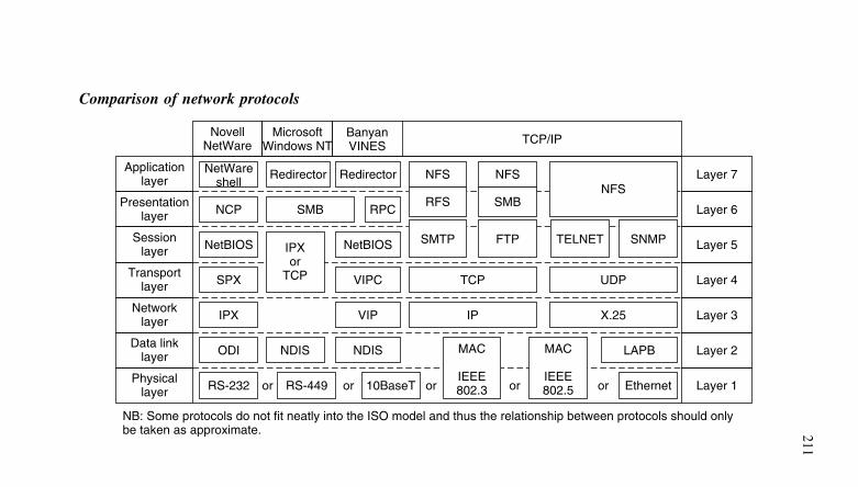
211
Comparison of network protocols
Physicallayer
Data linklayer
Networklayer
Transportlayer
Sessionlayer
Presentationlayer
Applicationlayer
NovellNetWare
MicrosoftWindows NT
BanyanVINES
Layer 7
TCP/IP
Layer 6
Layer 5
Layer 4
Layer 3
Layer 2
Layer 1
NetWareshell
or
NB: Some protocols do not fit neatly into the ISO model and thus the relationship between protocols should onlybe taken as approximate.
RS-232 or or or orRS-449 10BaseT
x
Ethernet
LAPBODI
IPX
SPX
NetBIOS
NCP
Redirector Redirector
NDIS
SMB
NFS
RFS
NDIS
VIP
VIPC TCP
IP
NetBIOS SMTP
NFS
SMB
FTP
UDP
X.25
TELNET SNMP
RPC
MAC
IEEE802.3
MAC
IEEE802.5
NFS
IPXor
TCP
11 Reference information
ITU-T recommendations
The International Telecommunications Union – Telecommunications(ITU-T) produces internationally agreed standards for telecommunica-tions. These standards appear as a number of recommendations whichcover telecommunications apparatus and the transmission of both ana-log and digital signals.
The International Telecommunications Union (ITU) is the parentbody for the ITU-T and is itself organised by and responsible to theUnited Nations.
The major ITU-T recommendations are organised into series whichdeal with data transmission over telephone circuits (V-series rec-ommendations), data networks (X-series recommendations), digitalnetworks (G-series recommendations), and integrated services digitalnetworks (I-series recommendations).
ITU-T G-series recommendations
The following ITU-T G-series recommendations relate to transmis-sion systems and multiplexing equipment characteristics of digitalnetworks:
G.701 General structure of the G.700, G.800 recommendationsG.702 Terminology used for pulse code modulation (PCM) and
digital transmissionG.703 General aspects of interfacesG.704 Maintenance of digital networksG.705 Integrated services digital networks (ISDN)G.706 Frame alignment and cyclic redundancy check (CRC) pro-
cedures relating to G.704G.707 Network node interface for the synchronous digital hierar-
chy (SDH)G.711 Pulse code modulation (PCM) of voice frequenciesG.712 Performance characteristics of PCM channels at audio fre-
quenciesG.720 Characterization of low-rate digital voice coder perfor-
mance with non-voice signalsG.721 Hypothetical reference digital pathsG.722 7 kHz audio-coding within 64 kbit/s
213
G.723.1 Dual rate speech coder for multimedia communicationstransmitting at 5.3 and 6.3 kbit/s. Annex A covers thesilence compression scheme
G.724 Characteristics of a 48-channel low bit rate encoding pri-mary multiplex operating at 1544 kbit/s
G.725 System aspects for the use of the 7 kHz audio codec within64 kbit/s
G.726 40, 32, 24, 16 kbit/s adaptive differential pulse code mod-ulation (ADPCM)
G.727 5-, 4-, 3- and 2-bits/sample embedded adaptive differentialpulse code modulation (ADPCM)
G.728 Coding of speech at 16 kbit/s using low-delay code excitedlinear prediction. Annex H describes variable bit rate LD-CELP operation mainly for DCME at rates less than16 kbit/s
G.729 Coding of speech at 8 kbit/s using Conjugate-StructureAlgebraic-Code-Excited Linear-Prediction (CS-ACELP).Anex D describes a 6.4 kbit/s CS-ACELP speech codingalgorithm and annex E describes a 11.8 kbit/s CS-ACELPspeech coding algorithm
G.731 Primary PCM multiplex equipment for voice frequenciesG.732 Characteristic of primary PCM multiplex equipment oper-
ating at 2048 kbpsG.733 Characteristics of primary PCM multiplex equipment oper-
ating at 1544 kbpsG.734 Frame structure for use with digital exchanges at 2048 kbpsG.735 Termination of 1544 kbps digital paths on digital exchangesG.736 Characteristics of synchronous digital multiplex equipment
operating at 1544 kbpsG.737 Characteristics of primary PCM multiplex equipment oper-
ating at 2048 kbps and offering synchronous 64 kbps digitalaccess options
G.738 Characteristics of synchronous digital multiplex equipmentoperating at 2048 kbps
G.739 Characteristics of external access equipment operatingat 2048 kbps and offering synchronous digital access at64 kbps
G.741 General considerations on second order multiplex equip-ments
G.742 Second order digital multiplex equipment operating at8448 kbps and using positive justification
214
G.743 Second order digital multiplex equipment operating at6312 kbps and using positive justification
G.744 Second order PCM multiplex equipment operating at8448 kbps
G.745 Second order digital multiplex equipment operating at8448 kbps and using positive/zero/negative justification
G.746 Frame structure for use with digital exchanges at 8448 kbpsG.751 Digital multiplex equipment operating at third order
bit rates of 34 368 kbps and fourth order bit rates of139 264 kbps and using positive justification
G.752 Characteristics of digital multiplex equipment based on sec-ond order bit rates of 6312 kbps and using positive justifi-cation
G.753 Third order digital multiplex equipment operating at34 368 kbps and using positive/zero/negative justification
G.754 Fourth order digital multiplex equipment operating at139 264 kbps and using positive/zero.negative justification
G.755 Digital multiplex equipment operating at 139 264 kbit/s andmultiplexing three tributaries at 44 736 kbit/s
G.763 Digital circuit multiplication equipment using ADPCM(G.726) and digital speech interpolation
G.764 Voice packetisation protocolsG.765 Packet circuit multiplication equipmentG.766 Facsimile demodulation/remodulation for digital circuit
multiplication equipmentG.767 Digital circuit multiplication equipment using 16 kbit/s LD-
CELPG.780 Vocabulary of terms for synchronous digital hierarchy
(SDH)G.783 Characteristics of synchronous digital hierarchy (SDH)
equipmentG.784 Synchronous digital hierarchy (SDH) management
ITU-T I-series recommendations
The following ITU-T I-series recommendations relate to integratedservices digital networks (ISDNs):
I.110 General structure of the I-series recommendationsI.111 Relationship with other recommendations relevant to ISDNI.112 Vocabulary of terms for ISDNI.113 Vocabulary of terms for broadband aspects of ISDNI.114 Vocabulary of terms for universal personal telecommun-
ication
215
I.120 ISDN descriptionI.121 Broadband aspects of ISDNI.122 Framework for frame mode bearer servicesI.130 Method for the characterisation of telecommunication ser-
vices supported by an ISDN and network capabilities of anISDN
I.150 Broadband-ISDN ATM functional characteristicsI.210 Principles of telecommunication services supported by an
ISDNI.211 Broadband-ISDN service aspectsI.231.x Voice coding for ISDN bearer serviceI.241.x Teleservices supported by ISDNI.250 Definition of supplementary servicesI.251.x Number identification supplementary servicesI.252.x Call offering supplementary servicesI.253.x Call completion supplementary servicesI.254.x Multiparty supplementary servicesI.255.x Community of interest supplementary servicesI.256.x Charging supplementary servicesI.310 ISDN network functional principlesI.311 Broadband-ISDN general network aspectsI.312 Principles of intelligent network architectureI.313 Broadband-ISDN network requirementsI.320 ISDN protocol reference modelI.321 B-ISDN protocol reference model and its applicationI.322 Generic protocol reference model for telecommunication net-
worksI.324 ISDN network architectureI.325 Reference configurations for ISDN connection typesI.326 Functional architecture of transport networks based on ATMI.327 Broadband-ISDN functional architectureI.330 ISDN numbering and addressing principlesI.331 ISDN numbering planI.340 ISDN connection typesI.35x Quality of service and network performanceI.410 General aspects and principles relating to recommendations
on ISDN user network interfacesI.411 ISDN user-network interfaces – reference configurationsI.412 ISDN user-network interfaces – channel structures and
access capabilitiesI.413 Broadband-ISDN user-network interfaceI.414 Overview for ISDN and B-ISDN customer access
216
I.420 Basic access user-network interfaceI.421 Primary rate user-network interfaceI.430 Basic user-network interface – layer 1 specificationI.431 Primary rate user-network interface – layer 1 specificationI.432.x Higher rate user-network interfaceI.440 ISDN user-network interface: layer 2 – general aspects
(Q.920)I.441 ISDN user-network interface data link specification (Q.921)I.450 ISDN layer 3 specification (Q.931)I.460 Multiplexing, rate adaption and support of existing interfacesI.461 Support of X.21 and X.21 bis based DTEs by an ISDN
(X.30)I.462 Support of packet mode terminal equipment by an ISDN
(X.31)I.463 Support of DTEs with V-series type interfaces by an ISDN
(V.110)I.464 Rate adaption multiplexing and support of existing interfaces
for restricted 64 kbps transfer capabilityI.465 Support by an ISDN of data terminal equipment with V-
series interfaces (V.120)I.731 Types and general characteristics of ATM equipmentI.732 Functional characteristics of ATM equipment
ITU-T V-series recommendations
The following ITU-T V-series recommendations cover data transmis-sion over the telephone network:
V.1 Equivalence between binary notation symbols and the sig-nificant conditions of a two condition code
V.2 Power levels for data transmission over telephone linesV.3 International alphabet no. 5V.4 General structure of signals of international alphabet no. 5
code for data transmission over public telephone networksV.5 Standards of modulation rates and data signalling rates for
synchronous data transmission in the general switched net-work
V.6 Standards of modulation rates and data signalling rates forsynchronous data transmission on leased telephone-typecircuits
V.7 Definitions of terms concerning data transmission over thetelephone network
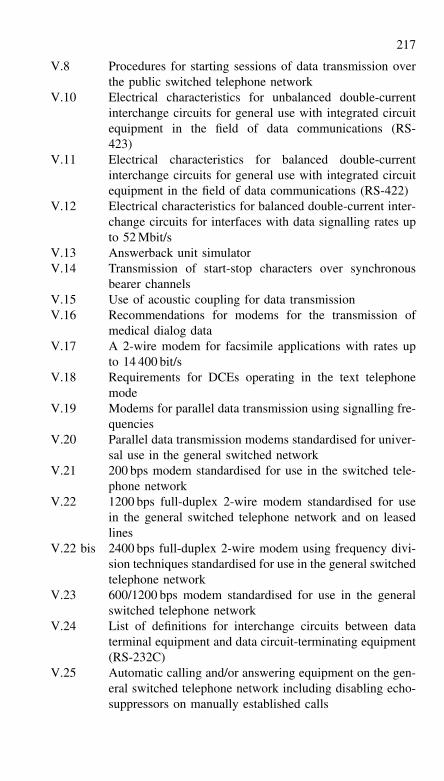
217
V.8 Procedures for starting sessions of data transmission overthe public switched telephone network
V.10 Electrical characteristics for unbalanced double-currentinterchange circuits for general use with integrated circuitequipment in the field of data communications (RS-423)
V.11 Electrical characteristics for balanced double-currentinterchange circuits for general use with integrated circuitequipment in the field of data communications (RS-422)
V.12 Electrical characteristics for balanced double-current inter-change circuits for interfaces with data signalling rates upto 52 Mbit/s
V.13 Answerback unit simulatorV.14 Transmission of start-stop characters over synchronous
bearer channelsV.15 Use of acoustic coupling for data transmissionV.16 Recommendations for modems for the transmission of
medical dialog dataV.17 A 2-wire modem for facsimile applications with rates up
to 14 400 bit/sV.18 Requirements for DCEs operating in the text telephone
modeV.19 Modems for parallel data transmission using signalling fre-
quenciesV.20 Parallel data transmission modems standardised for univer-
sal use in the general switched networkV.21 200 bps modem standardised for use in the switched tele-
phone networkV.22 1200 bps full-duplex 2-wire modem standardised for use
in the general switched telephone network and on leasedlines
V.22 bis 2400 bps full-duplex 2-wire modem using frequency divi-sion techniques standardised for use in the general switchedtelephone network
V.23 600/1200 bps modem standardised for use in the generalswitched telephone network
V.24 List of definitions for interchange circuits between dataterminal equipment and data circuit-terminating equipment(RS-232C)
V.25 Automatic calling and/or answering equipment on the gen-eral switched telephone network including disabling echo-suppressors on manually established calls
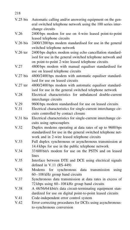
218
V.25 bis Automatic calling and/or answering equipment on the gen-eral switched telephone network using the 100 series inter-change circuits
V.26 2400 bps modem for use on 4-wire leased point-to-pointleased telephone circuits
V.26 bis 2400/1200 bps modem standardised for use in the generalswitched telephone network
V.26 ter 2400 bps duplex modem using echo cancellation standard-ised for use in the general switched telephone network andon point-to-point 2-wire leased telephone circuits
V.27 4800 bps modem with manual equaliser standardised foruse on leased telephone circuits
V.27 bis 4800/2400 bps modem with automatic equaliser standard-ised for use on leased circuits
V.27 ter 4800/2400 bps modem with automatic equaliser standard-ised for use in the general switched telephone network
V.28 Electrical characteristics for unbalanced double-currentinterchange circuits
V.29 9600 bps modem standardised for use on leased circuitsV.31 Electrical characteristics for single-current interchange cir-
cuits controlled by contact closureV.31 bis Electrical characteristics for single-current interchange cir-
cuits using optocouplersV.32 Duplex modems operating at data rates of up to 9600 bps
standardised for use in the general switched telephone net-work and in 2-wire leased telephone circuits
V.33 Full duplex synchronous or asynchronous transmission at14.4 kbps for use in the public telephone network
V.34 33 600 bit/s modem for use on the PSTN and on leasedlines
V.35 Interface between DTE and DCE using electrical signalsdefined in V.11 (RS-449)
V.36 Modems for synchronous data transmission using60–108 kHz group band circuits
V.37 Synchronous data transmission at data rates in excess of72 kbps using 60–108 kHz group band circuits
V.38 A 48/56/64 kbit/s data circuit-terminating equipment stan-dardized for use on digital point-to-point leased circuits
V.41 Code-independent error control systemV.42 Error-correcting procedures for DCEs using asynchronous-
to-synchronous conversion
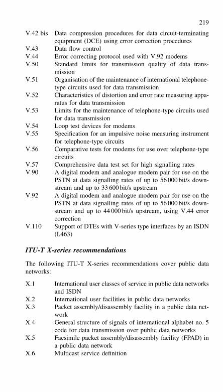
219
V.42 bis Data compression procedures for data circuit-terminatingequipment (DCE) using error correction procedures
V.43 Data flow controlV.44 Error correcting protocol used with V.92 modemsV.50 Standard limits for transmission quality of data trans-
missionV.51 Organisation of the maintenance of international telephone-
type circuits used for data transmissionV.52 Characteristics of distortion and error rate measuring appa-
ratus for data transmissionV.53 Limits for the maintenance of telephone-type circuits used
for data transmissionV.54 Loop test devices for modemsV.55 Specification for an impulsive noise measuring instrument
for telephone-type circuitsV.56 Comparative tests for modems for use over telephone-type
circuitsV.57 Comprehensive data test set for high signalling ratesV.90 A digital modem and analogue modem pair for use on the
PSTN at data signalling rates of up to 56 000 bit/s down-stream and up to 33 600 bit/s upstream
V.92 A digital modem and analogue modem pair for use on thePSTN at data signalling rates of up to 56 000 bit/s down-stream and up to 44 000 bit/s upstream, using V.44 errorcorrection
V.110 Support of DTEs with V-series type interfaces by an ISDN(I.463)
ITU-T X-series recommendations
The following ITU-T X-series recommendations cover public datanetworks:
X.1 International user classes of service in public data networksand ISDN
X.2 International user facilities in public data networksX.3 Packet assembly/disassembly facility in a public data net-
workX.4 General structure of signals of international alphabet no. 5
code for data transmission over public data networksX.5 Facsimile packet assembly/disassembly facility (FPAD) in
a public data networkX.6 Multicast service definition
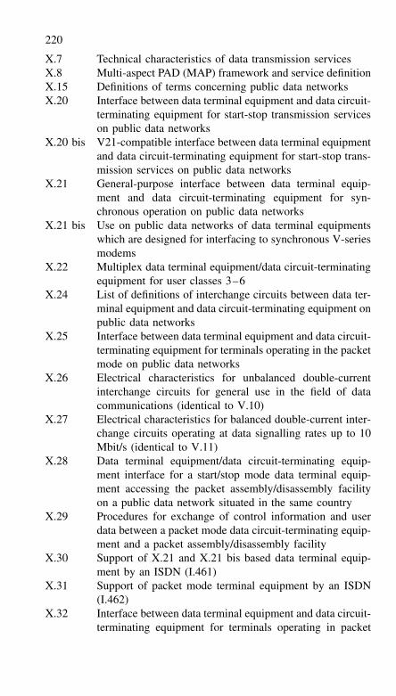
220
X.7 Technical characteristics of data transmission servicesX.8 Multi-aspect PAD (MAP) framework and service definitionX.15 Definitions of terms concerning public data networksX.20 Interface between data terminal equipment and data circuit-
terminating equipment for start-stop transmission serviceson public data networks
X.20 bis V21-compatible interface between data terminal equipmentand data circuit-terminating equipment for start-stop trans-mission services on public data networks
X.21 General-purpose interface between data terminal equip-ment and data circuit-terminating equipment for syn-chronous operation on public data networks
X.21 bis Use on public data networks of data terminal equipmentswhich are designed for interfacing to synchronous V-seriesmodems
X.22 Multiplex data terminal equipment/data circuit-terminatingequipment for user classes 3–6
X.24 List of definitions of interchange circuits between data ter-minal equipment and data circuit-terminating equipment onpublic data networks
X.25 Interface between data terminal equipment and data circuit-terminating equipment for terminals operating in the packetmode on public data networks
X.26 Electrical characteristics for unbalanced double-currentinterchange circuits for general use in the field of datacommunications (identical to V.10)
X.27 Electrical characteristics for balanced double-current inter-change circuits operating at data signalling rates up to 10Mbit/s (identical to V.11)
X.28 Data terminal equipment/data circuit-terminating equip-ment interface for a start/stop mode data terminal equip-ment accessing the packet assembly/disassembly facilityon a public data network situated in the same country
X.29 Procedures for exchange of control information and userdata between a packet mode data circuit-terminating equip-ment and a packet assembly/disassembly facility
X.30 Support of X.21 and X.21 bis based data terminal equip-ment by an ISDN (I.461)
X.31 Support of packet mode terminal equipment by an ISDN(I.462)
X.32 Interface between data terminal equipment and data circuit-terminating equipment for terminals operating in packet
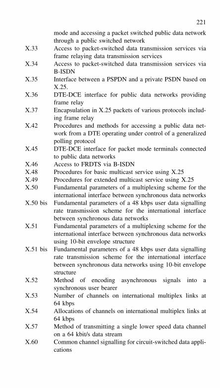
221
mode and accessing a packet switched public data networkthrough a public switched network
X.33 Access to packet-switched data transmission services viaframe relaying data transmission services
X.34 Access to packet-switched data transmission services viaB-ISDN
X.35 Interface between a PSPDN and a private PSDN based onX.25.
X.36 DTE-DCE interface for public data networks providingframe relay
X.37 Encapsulation in X.25 packets of various protocols includ-ing frame relay
X.42 Procedures and methods for accessing a public data net-work from a DTE operating under control of a generalizedpolling protocol
X.45 DTE-DCE interface for packet mode terminals connectedto public data networks
X.46 Access to FRDTS via B-ISDNX.48 Procedures for basic multicast service using X.25X.49 Procedures for extended multicast service using X.25X.50 Fundamental parameters of a multiplexing scheme for the
international interface between synchronous data networksX.50 bis Fundamental parameters of a 48 kbps user data signalling
rate transmission scheme for the international interfacebetween synchronous data networks
X.51 Fundamental parameters of a multiplexing scheme for theinternational interface between synchronous data networksusing 10-bit envelope structure
X.51 bis Fundamental parameters of a 48 kbps user data signallingrate transmission scheme for the international interfacebetween synchronous data networks using 10-bit envelopestructure
X.52 Method of encoding asynchronous signals into asynchronous user bearer
X.53 Number of channels on international multiplex links at64 kbps
X.54 Allocations of channels on international multiplex links at64 kbps
X.57 Method of transmitting a single lower speed data channelon a 64 kbit/s data stream
X.60 Common channel signalling for circuit-switched data appli-cations
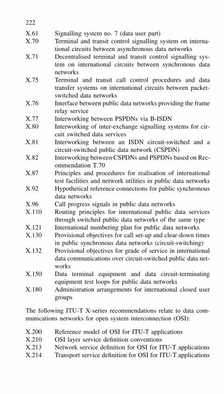
222
X.61 Signalling system no. 7 (data user part)X.70 Terminal and transit control signalling system on interna-
tional circuits between asynchronous data networksX.71 Decentralised terminal and transit control signalling sys-
tem on international circuits between synchronous datanetworks
X.75 Terminal and transit call control procedures and datatransfer systems on international circuits between packet-switched data networks
X.76 Interface between public data networks providing the framerelay service
X.77 Interworking between PSPDNs via B-ISDNX.80 Interworking of inter-exchange signalling systems for cir-
cuit switched data servicesX.81 Interworking between an ISDN circuit-switched and a
circuit-switched public data network (CSPDN)X.82 Interworking between CSPDNs and PSPDNs based on Rec-
ommendation T.70X.87 Principles and procedures for realisation of international
test facilities and network utilities in public data networksX.92 Hypothetical reference connections for public synchronous
data networksX.96 Call progress signals in public data networksX.110 Routing principles for international public data services
through switched public data networks of the same typeX.121 International numbering plan for public data networksX.130 Provisional objectives for call set-up and clear-down times
in public synchronous data networks (circuit-switching)X.132 Provisional objectives for grade of service in international
data communications over circuit-switched public data net-works
X.150 Data terminal equipment and data circuit-terminatingequipment test loops for public data networks
X.180 Administration arrangements for international closed usergroups
The following ITU-T X-series recommendations relate to data com-munications networks for open system interconnection (OSI):
X.200 Reference model of OSI for ITU-T applicationsX.210 OSI layer service definition conventionsX.213 Network service definition for OSI for ITU-T applicationsX.214 Transport service definition for OSI for ITU-T applications
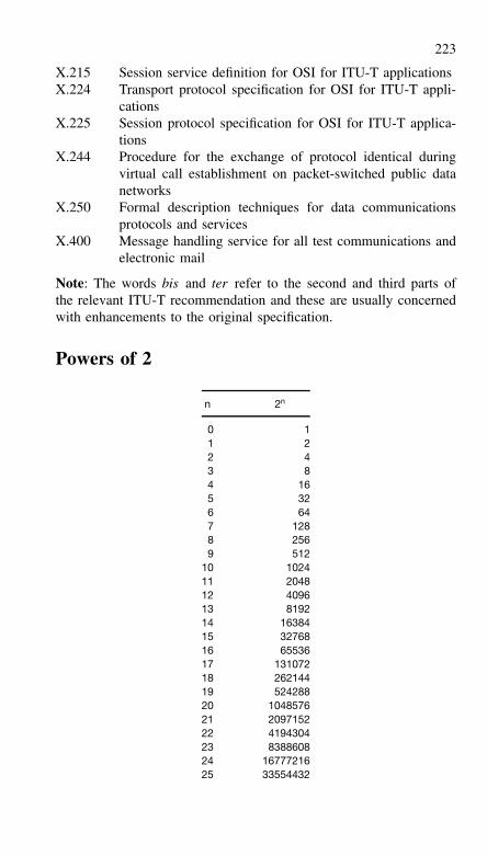
223
X.215 Session service definition for OSI for ITU-T applicationsX.224 Transport protocol specification for OSI for ITU-T appli-
cationsX.225 Session protocol specification for OSI for ITU-T applica-
tionsX.244 Procedure for the exchange of protocol identical during
virtual call establishment on packet-switched public datanetworks
X.250 Formal description techniques for data communicationsprotocols and services
X.400 Message handling service for all test communications andelectronic mail
Note: The words bis and ter refer to the second and third parts ofthe relevant ITU-T recommendation and these are usually concernedwith enhancements to the original specification.
Powers of 2
n 2n
0 11 22 43 84 165 326 647 1288 2569 512
10 102411 204812 409613 819214 1638415 3276816 6553617 13107218 26214419 52428820 104857621 209715222 419430423 838860824 1677721625 33554432
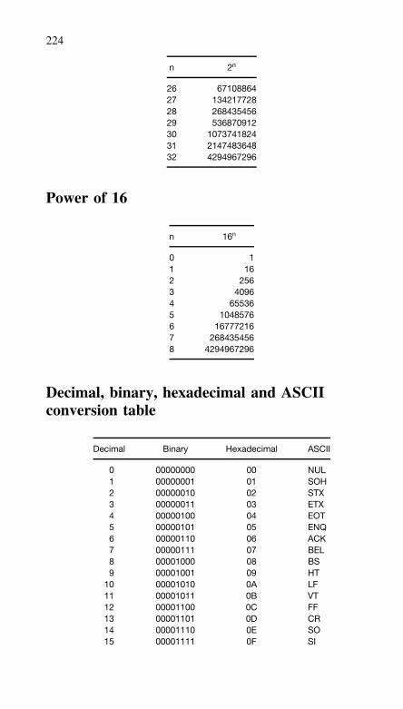
224
n 2n
26 6710886427 13421772828 26843545629 53687091230 107374182431 214748364832 4294967296
Power of 16
n 16n
0 11 162 2563 40964 655365 10485766 167772167 2684354568 4294967296
Decimal, binary, hexadecimal and ASCIIconversion table
Decimal Binary Hexadecimal ASCII
0 00000000 00 NUL1 00000001 01 SOH2 00000010 02 STX3 00000011 03 ETX4 00000100 04 EOT5 00000101 05 ENQ6 00000110 06 ACK7 00000111 07 BEL8 00001000 08 BS9 00001001 09 HT
10 00001010 0A LF11 00001011 0B VT12 00001100 0C FF13 00001101 0D CR14 00001110 0E SO15 00001111 0F SI
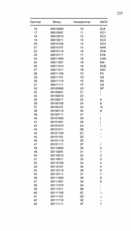
225
Decimal Binary Hexadecimal ASCII
16 00010000 10 DLE17 00010001 11 DC118 00010010 12 DC219 00010011 13 DC320 00010100 14 DC421 00010101 15 NAK22 00010110 16 SYN23 00010111 17 ETB24 00011000 18 CAN25 00011001 19 EM26 00011010 1A SUB27 00011011 1B ESC28 00011100 1C FS29 00011101 1D GS30 00011110 1E RS31 00011111 1F US32 00100000 20 SP33 00100001 21 !34 00100010 22 ′′35 00100011 23 #36 00100100 24 $37 00100101 25 %38 00100110 26 &39 00100111 27 ’40 00101000 28 (41 00101001 29 )42 00101010 2A *43 00101011 2B +44 00101100 2C ,45 00101101 2D −46 00101110 2E .47 00101111 2F /48 00110000 30 049 00110001 31 150 00110010 32 251 00110011 33 352 00110100 34 453 00110101 35 554 00110110 36 655 00110111 37 756 00111000 38 857 00111001 39 958 00111010 3A :59 00111011 3B ;60 00111100 3C <
61 00111101 3D =62 00111110 3E >
63 00111111 3F ?
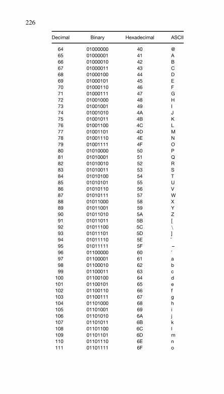
226
Decimal Binary Hexadecimal ASCII
64 01000000 40 @65 01000001 41 A66 01000010 42 B67 01000011 43 C68 01000100 44 D69 01000101 45 E70 01000110 46 F71 01000111 47 G72 01001000 48 H73 01001001 49 I74 01001010 4A J75 01001011 4B K76 01001100 4C L77 01001101 4D M78 01001110 4E N79 01001111 4F O80 01010000 50 P81 01010001 51 Q82 01010010 52 R83 01010011 53 S84 01010100 54 T85 01010101 55 U86 01010110 56 V87 01010111 57 W88 01011000 58 X89 01011001 59 Y90 01011010 5A Z91 01011011 5B [92 01011100 5C \93 01011101 5D ]94 01011110 5E ˆ95 01011111 5F –96 01100000 60 ′97 01100001 61 a98 01100010 62 b99 01100011 63 c
100 01100100 64 d101 01100101 65 e102 01100110 66 f103 01100111 67 g104 01101000 68 h105 01101001 69 i106 01101010 6A j107 01101011 6B k108 01101100 6C l109 01101101 6D m110 01101110 6E n111 01101111 6F o
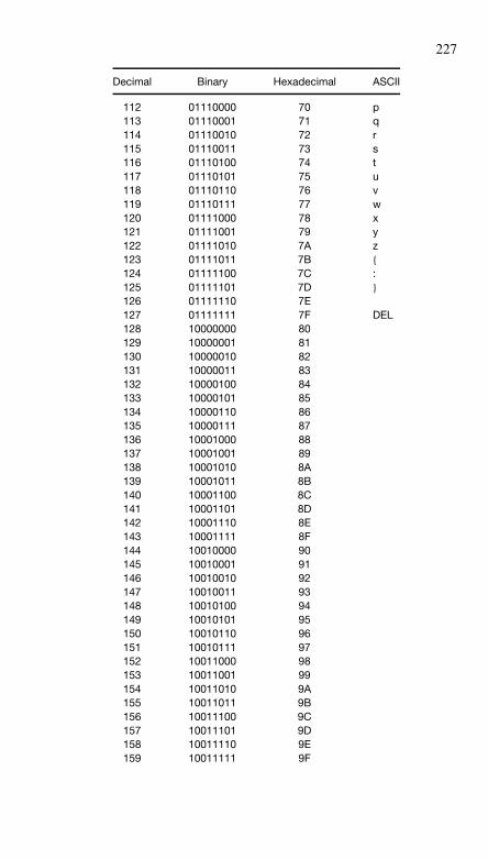
227
Decimal Binary Hexadecimal ASCII
112 01110000 70 p113 01110001 71 q114 01110010 72 r115 01110011 73 s116 01110100 74 t117 01110101 75 u118 01110110 76 v119 01110111 77 w120 01111000 78 x121 01111001 79 y122 01111010 7A z123 01111011 7B {124 01111100 7C :125 01111101 7D }126 01111110 7E127 01111111 7F DEL128 10000000 80129 10000001 81130 10000010 82131 10000011 83132 10000100 84133 10000101 85134 10000110 86135 10000111 87136 10001000 88137 10001001 89138 10001010 8A139 10001011 8B140 10001100 8C141 10001101 8D142 10001110 8E143 10001111 8F144 10010000 90145 10010001 91146 10010010 92147 10010011 93148 10010100 94149 10010101 95150 10010110 96151 10010111 97152 10011000 98153 10011001 99154 10011010 9A155 10011011 9B156 10011100 9C157 10011101 9D158 10011110 9E159 10011111 9F
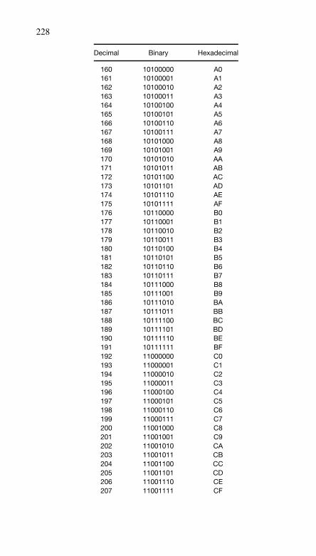
228
Decimal Binary Hexadecimal
160 10100000 A0161 10100001 A1162 10100010 A2163 10100011 A3164 10100100 A4165 10100101 A5166 10100110 A6167 10100111 A7168 10101000 A8169 10101001 A9170 10101010 AA171 10101011 AB172 10101100 AC173 10101101 AD174 10101110 AE175 10101111 AF176 10110000 B0177 10110001 B1178 10110010 B2179 10110011 B3180 10110100 B4181 10110101 B5182 10110110 B6183 10110111 B7184 10111000 B8185 10111001 B9186 10111010 BA187 10111011 BB188 10111100 BC189 10111101 BD190 10111110 BE191 10111111 BF192 11000000 C0193 11000001 C1194 11000010 C2195 11000011 C3196 11000100 C4197 11000101 C5198 11000110 C6199 11000111 C7200 11001000 C8201 11001001 C9202 11001010 CA203 11001011 CB204 11001100 CC205 11001101 CD206 11001110 CE207 11001111 CF
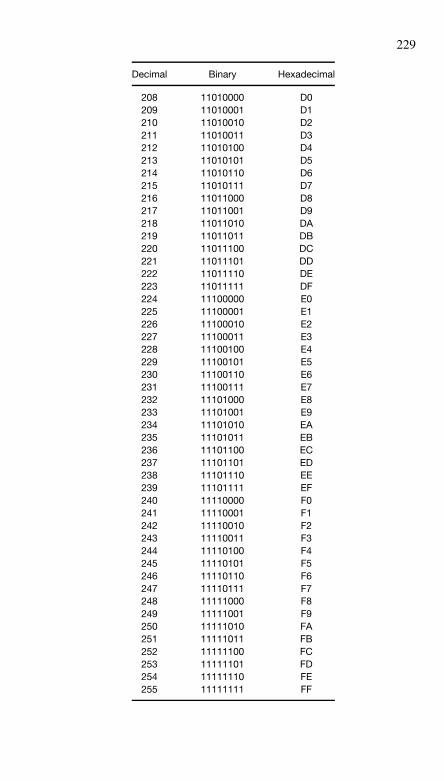
229
Decimal Binary Hexadecimal
208 11010000 D0209 11010001 D1210 11010010 D2211 11010011 D3212 11010100 D4213 11010101 D5214 11010110 D6215 11010111 D7216 11011000 D8217 11011001 D9218 11011010 DA219 11011011 DB220 11011100 DC221 11011101 DD222 11011110 DE223 11011111 DF224 11100000 E0225 11100001 E1226 11100010 E2227 11100011 E3228 11100100 E4229 11100101 E5230 11100110 E6231 11100111 E7232 11101000 E8233 11101001 E9234 11101010 EA235 11101011 EB236 11101100 EC237 11101101 ED238 11101110 EE239 11101111 EF240 11110000 F0241 11110001 F1242 11110010 F2243 11110011 F3244 11110100 F4245 11110101 F5246 11110110 F6247 11110111 F7248 11111000 F8249 11111001 F9250 11111010 FA251 11111011 FB252 11111100 FC253 11111101 FD254 11111110 FE255 11111111 FF
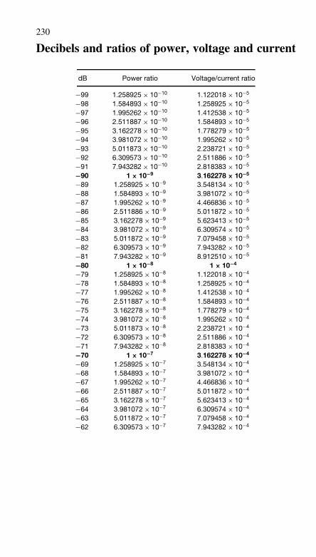
230
Decibels and ratios of power, voltage and current
dB Power ratio Voltage/current ratio
−99 1.258925 × 10⁻¹⁰ 1.122018 × 10⁻⁵
−98 1.584893 × 10⁻¹⁰ 1.258925 × 10⁻⁵
−97 1.995262 × 10⁻¹⁰ 1.412538 × 10⁻⁵
−96 2.511887 × 10⁻¹⁰ 1.584893 × 10⁻⁵
−95 3.162278 × 10⁻¹⁰ 1.778279 × 10⁻⁵
−94 3.981072 × 10⁻¹⁰ 1.995262 × 10⁻⁵
−93 5.011873 × 10⁻¹⁰ 2.238721 × 10⁻⁵
−92 6.309573 × 10⁻¹⁰ 2.511886 × 10⁻⁵
−91 7.943282 × 10⁻¹⁰ 2.818383 × 10⁻⁵
−90 1 × 10⁻⁹ 3.162278 × 10⁻⁵
−89 1.258925 × 10⁻⁹ 3.548134 × 10⁻⁵
−88 1.584893 × 10⁻⁹ 3.981072 × 10⁻⁵
−87 1.995262 × 10⁻⁹ 4.466836 × 10⁻⁵
−86 2.511886 × 10⁻⁹ 5.011872 × 10⁻⁵
−85 3.162278 × 10⁻⁹ 5.623413 × 10⁻⁵
−84 3.981072 × 10⁻⁹ 6.309574 × 10⁻⁵
−83 5.011872 × 10⁻⁹ 7.079458 × 10⁻⁵
−82 6.309573 × 10⁻⁹ 7.943282 × 10⁻⁵
−81 7.943282 × 10⁻⁹ 8.912510 × 10⁻⁵
−80 1 × 10⁻⁸ 1 × 10⁻⁴
−79 1.258925 × 10⁻⁸ 1.122018 × 10⁻⁴
−78 1.584893 × 10⁻⁸ 1.258925 × 10⁻⁴
−77 1.995262 × 10⁻⁸ 1.412538 × 10⁻⁴
−76 2.511887 × 10⁻⁸ 1.584893 × 10⁻⁴
−75 3.162278 × 10⁻⁸ 1.778279 × 10⁻⁴
−74 3.981072 × 10⁻⁸ 1.995262 × 10⁻⁴
−73 5.011873 × 10⁻⁸ 2.238721 × 10⁻⁴
−72 6.309573 × 10⁻⁸ 2.511886 × 10⁻⁴
−71 7.943282 × 10⁻⁸ 2.818383 × 10⁻⁴
−70 1 × 10⁻⁷ 3.162278 × 10⁻⁴
−69 1.258925 × 10⁻⁷ 3.548134 × 10⁻⁴
−68 1.584893 × 10⁻⁷ 3.981072 × 10⁻⁴
−67 1.995262 × 10⁻⁷ 4.466836 × 10⁻⁴
−66 2.511887 × 10⁻⁷ 5.011872 × 10⁻⁴
−65 3.162278 × 10⁻⁷ 5.623413 × 10⁻⁴
−64 3.981072 × 10⁻⁷ 6.309574 × 10⁻⁴
−63 5.011872 × 10⁻⁷ 7.079458 × 10⁻⁴
−62 6.309573 × 10⁻⁷ 7.943282 × 10⁻⁴
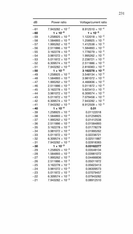
231
dB Power ratio Voltage/current ratio
−61 7.943282 × 10⁻⁷ 8.912510 × 10⁻⁴
−60 1 × 10⁻⁶ 1 × 10⁻³
−59 1.258925 × 10⁻⁶ 1.122018 × 10⁻³
−58 1.584893 × 10⁻⁶ 1.258925 × 10⁻³
−57 1.995262 × 10⁻⁶ 1.412538 × 10⁻³
−56 2.511886 × 10⁻⁶ 1.584893 × 10⁻³
−55 3.162278 × 10⁻⁶ 1.778279 × 10⁻³
−54 3.981072 × 10⁻⁶ 1.995262 × 10⁻³
−53 5.011872 × 10⁻⁶ 2.238721 × 10⁻³
−52 6.309574 × 10⁻⁶ 2.511886 × 10⁻³
−51 7.943282 × 10⁻⁶ 2.818383 × 10⁻³
−50 1 × 10⁻⁵ 3.162278 × 10⁻³
−49 1.258925 × 10⁻⁵ 3.548134 × 10⁻³
−48 1.584893 × 10⁻⁵ 3.981072 × 10⁻³
−47 1.995262 × 10⁻⁵ 4.466836 × 10⁻³
−46 2.511886 × 10⁻⁵ 5.011872 × 10⁻³
−45 3.162278 × 10⁻⁵ 5.623413 × 10⁻³
−44 3.981072 × 10⁻⁵ 6.309574 × 10⁻³
−43 5.011872 × 10⁻⁵ 7.079458 × 10⁻³
−42 6.309574 × 10⁻⁵ 7.943282 × 10⁻³
−41 7.943282 × 10⁻⁵ 8.912509 × 10⁻³
−40 1 × 10⁻⁴ 0.01−39 1.258925 × 10⁻⁴ 0.01122018−38 1.584893 × 10⁻⁴ 0.01258925−37 1.995262 × 10⁻⁴ 0.01412538−36 2.511886 × 10⁻⁴ 0.01584893−35 3.162278 × 10⁻⁴ 0.01778279−34 3.981072 × 10⁻⁴ 0.01995262−33 5.011872 × 10⁻⁴ 0.02238721−32 6.309574 × 10⁻⁴ 0.02511887−31 7.943282 × 10⁻⁴ 0.02818383−30 1 × 10⁻³ 0.03162277−29 1.258925 × 10⁻³ 0.03548134−28 1.584893 × 10⁻³ 0.03981072−27 1.995262 × 10⁻³ 0.04466836−26 2.511886 × 10⁻³ 0.05011872−25 3.162278 × 10⁻³ 0.05623413−24 3.981072 × 10⁻³ 0.06309573−23 5.011872 × 10⁻³ 0.07079457−22 6.309574 × 10⁻³ 0.07943282−21 7.943282 × 10⁻³ 0.08912510
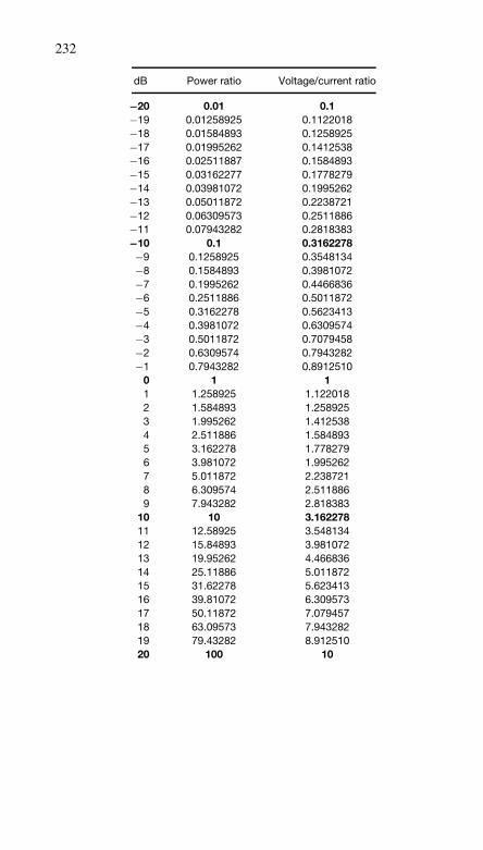
232
dB Power ratio Voltage/current ratio
−20 0.01 0.1−19 0.01258925 0.1122018−18 0.01584893 0.1258925−17 0.01995262 0.1412538−16 0.02511887 0.1584893−15 0.03162277 0.1778279−14 0.03981072 0.1995262−13 0.05011872 0.2238721−12 0.06309573 0.2511886−11 0.07943282 0.2818383−10 0.1 0.3162278−9 0.1258925 0.3548134−8 0.1584893 0.3981072−7 0.1995262 0.4466836−6 0.2511886 0.5011872−5 0.3162278 0.5623413−4 0.3981072 0.6309574−3 0.5011872 0.7079458−2 0.6309574 0.7943282−1 0.7943282 0.8912510
0 1 11 1.258925 1.1220182 1.584893 1.2589253 1.995262 1.4125384 2.511886 1.5848935 3.162278 1.7782796 3.981072 1.9952627 5.011872 2.2387218 6.309574 2.5118869 7.943282 2.818383
10 10 3.16227811 12.58925 3.54813412 15.84893 3.98107213 19.95262 4.46683614 25.11886 5.01187215 31.62278 5.62341316 39.81072 6.30957317 50.11872 7.07945718 63.09573 7.94328219 79.43282 8.91251020 100 10
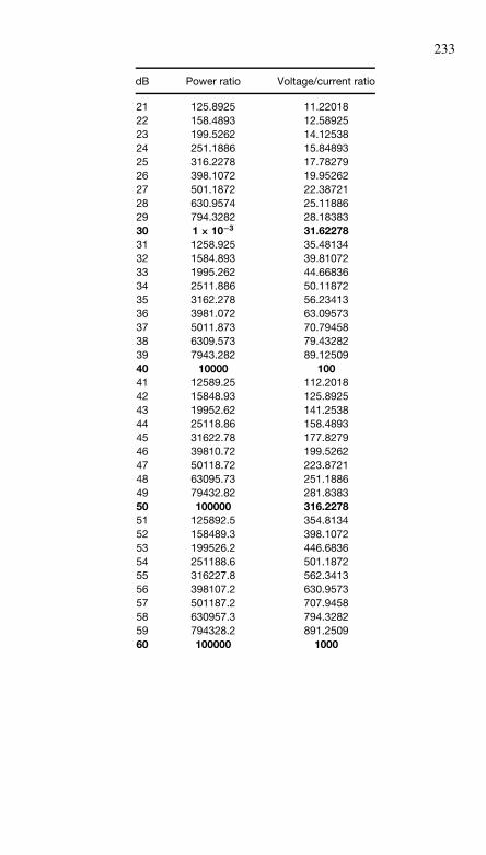
233
dB Power ratio Voltage/current ratio
21 125.8925 11.2201822 158.4893 12.5892523 199.5262 14.1253824 251.1886 15.8489325 316.2278 17.7827926 398.1072 19.9526227 501.1872 22.3872128 630.9574 25.1188629 794.3282 28.1838330 1 × 10⁻³ 31.6227831 1258.925 35.4813432 1584.893 39.8107233 1995.262 44.6683634 2511.886 50.1187235 3162.278 56.2341336 3981.072 63.0957337 5011.873 70.7945838 6309.573 79.4328239 7943.282 89.1250940 10000 10041 12589.25 112.201842 15848.93 125.892543 19952.62 141.253844 25118.86 158.489345 31622.78 177.827946 39810.72 199.526247 50118.72 223.872148 63095.73 251.188649 79432.82 281.838350 100000 316.227851 125892.5 354.813452 158489.3 398.107253 199526.2 446.683654 251188.6 501.187255 316227.8 562.341356 398107.2 630.957357 501187.2 707.945858 630957.3 794.328259 794328.2 891.250960 100000 1000
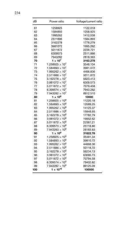
234
dB Power ratio Voltage/current ratio
61 1258925 1122.01862 1584893 1258.92563 1995262 1412.53864 2511886 1584.89365 3162278 1778.27966 3981072 1995.26267 5011872 2238.72168 6309573 2511.88669 7943282 2818.38370 1 × 10⁷ 3162.27871 1.258925 × 10⁷ 3548.13472 1.584893 × 10⁷ 3981.07273 1.995262 × 10⁷ 4466.83674 2.511886 × 10⁷ 5011.87275 3.162278 × 10⁷ 5623.41376 3.981072 × 10⁷ 6309.57377 5.011872 × 10⁷ 7079.45878 6.309574 × 10⁷ 7943.28279 7.943282 × 10⁷ 8912.51080 1 × 10⁸ 1000081 1.258925 × 10⁸ 11220.1882 1.584893 × 10⁸ 12589.2583 1.995262 × 10⁸ 14125.3784 2.511886 × 10⁸ 15848.9385 3.162278 × 10⁸ 17782.7986 3.981072 × 10⁸ 19952.6287 5.011872 × 10⁸ 22387.2188 6.309573 × 10⁸ 25118.8689 7.943283 × 10⁸ 28183.8390 1 × 10⁹ 31622.7891 1.258925 × 10⁹ 35481.3492 1.584893 × 10⁹ 39810.7293 1.995262 × 10⁹ 44668.3694 2.511886 × 10⁹ 50118.7295 3.162278 × 10⁹ 56234.1396 3.981072 × 10⁹ 63095.7397 5.011872 × 10⁹ 70794.5898 6.309574 × 10⁹ 79432.8299 7.943282 × 10⁹ 89125.09
100 1 × 10¹⁰ 100000
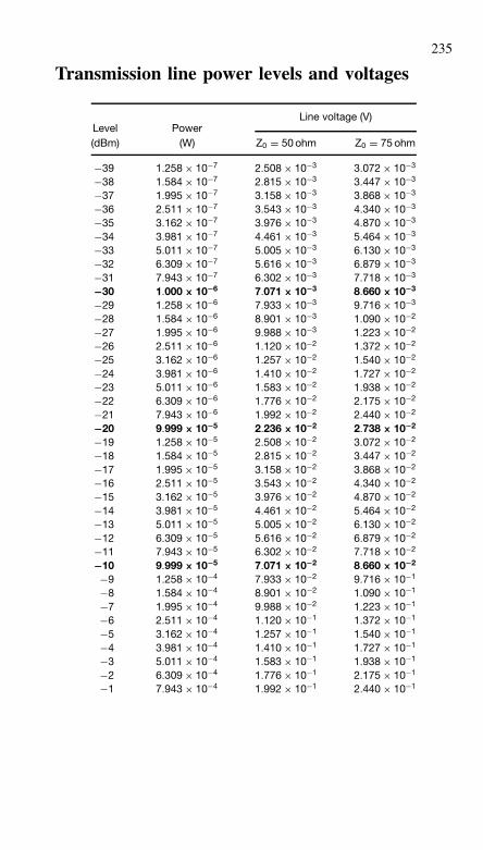
235
Transmission line power levels and voltages
Line voltage (V)Level Power(dBm) (W) Z0 = 50 ohm Z0 = 75 ohm
−39 1.258 × 10⁻⁷ 2.508 × 10⁻³ 3.072 × 10⁻³
−38 1.584 × 10⁻⁷ 2.815 × 10⁻³ 3.447 × 10⁻³
−37 1.995 × 10⁻⁷ 3.158 × 10⁻³ 3.868 × 10⁻³
−36 2.511 × 10⁻⁷ 3.543 × 10⁻³ 4.340 × 10⁻³
−35 3.162 × 10⁻⁷ 3.976 × 10⁻³ 4.870 × 10⁻³
−34 3.981 × 10⁻⁷ 4.461 × 10⁻³ 5.464 × 10⁻³
−33 5.011 × 10⁻⁷ 5.005 × 10⁻³ 6.130 × 10⁻³
−32 6.309 × 10⁻⁷ 5.616 × 10⁻³ 6.879 × 10⁻³
−31 7.943 × 10⁻⁷ 6.302 × 10⁻³ 7.718 × 10⁻³
−30 1.000 × 10⁻⁶ 7.071 × 10⁻³ 8.660 × 10⁻³
−29 1.258 × 10⁻⁶ 7.933 × 10⁻³ 9.716 × 10⁻³
−28 1.584 × 10⁻⁶ 8.901 × 10⁻³ 1.090 × 10⁻²
−27 1.995 × 10⁻⁶ 9.988 × 10⁻³ 1.223 × 10⁻²
−26 2.511 × 10⁻⁶ 1.120 × 10⁻² 1.372 × 10⁻²
−25 3.162 × 10⁻⁶ 1.257 × 10⁻² 1.540 × 10⁻²
−24 3.981 × 10⁻⁶ 1.410 × 10⁻² 1.727 × 10⁻²
−23 5.011 × 10⁻⁶ 1.583 × 10⁻² 1.938 × 10⁻²
−22 6.309 × 10⁻⁶ 1.776 × 10⁻² 2.175 × 10⁻²
−21 7.943 × 10⁻⁶ 1.992 × 10⁻² 2.440 × 10⁻²
−20 9.999 × 10⁻⁵ 2.236 × 10⁻² 2.738 × 10⁻²
−19 1.258 × 10⁻⁵ 2.508 × 10⁻² 3.072 × 10⁻²
−18 1.584 × 10⁻⁵ 2.815 × 10⁻² 3.447 × 10⁻²
−17 1.995 × 10⁻⁵ 3.158 × 10⁻² 3.868 × 10⁻²
−16 2.511 × 10⁻⁵ 3.543 × 10⁻² 4.340 × 10⁻²
−15 3.162 × 10⁻⁵ 3.976 × 10⁻² 4.870 × 10⁻²
−14 3.981 × 10⁻⁵ 4.461 × 10⁻² 5.464 × 10⁻²
−13 5.011 × 10⁻⁵ 5.005 × 10⁻² 6.130 × 10⁻²
−12 6.309 × 10⁻⁵ 5.616 × 10⁻² 6.879 × 10⁻²
−11 7.943 × 10⁻⁵ 6.302 × 10⁻² 7.718 × 10⁻²
−10 9.999 × 10⁻⁵ 7.071 × 10⁻² 8.660 × 10⁻²
−9 1.258 × 10⁻⁴ 7.933 × 10⁻² 9.716 × 10⁻¹
−8 1.584 × 10⁻⁴ 8.901 × 10⁻² 1.090 × 10⁻¹
−7 1.995 × 10⁻⁴ 9.988 × 10⁻² 1.223 × 10⁻¹
−6 2.511 × 10⁻⁴ 1.120 × 10⁻¹ 1.372 × 10⁻¹
−5 3.162 × 10⁻⁴ 1.257 × 10⁻¹ 1.540 × 10⁻¹
−4 3.981 × 10⁻⁴ 1.410 × 10⁻¹ 1.727 × 10⁻¹
−3 5.011 × 10⁻⁴ 1.583 × 10⁻¹ 1.938 × 10⁻¹
−2 6.309 × 10⁻⁴ 1.776 × 10⁻¹ 2.175 × 10⁻¹
−1 7.943 × 10⁻⁴ 1.992 × 10⁻¹ 2.440 × 10⁻¹
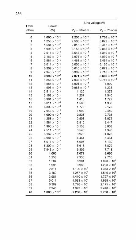
236
Line voltage (V)Level Power(dBm) (W) Z0 = 50 ohm Z0 = 75 ohm
0 1.000 × 10⁻³ 2.236 × 10⁻¹ 2.738 × 10⁻¹
1 1.258 × 10⁻³ 2.508 × 10⁻¹ 3.072 × 10⁻¹
2 1.584 × 10⁻³ 2.815 × 10⁻¹ 3.447 × 10⁻¹
3 1.995 × 10⁻³ 3.158 × 10⁻¹ 2.868 × 10⁻¹
4 2.511 × 10⁻³ 3.543 × 10⁻¹ 4.340 × 10⁻¹
5 3.162 × 10⁻³ 3.976 × 10⁻¹ 4.870 × 10⁻¹
6 3.981 × 10⁻³ 4.461 × 10⁻¹ 5.464 × 10⁻¹
7 5.011 × 10⁻³ 5.005 × 10⁻¹ 6.130 × 10⁻¹
8 6.309 × 10⁻³ 5.616 × 10⁻¹ 6.879 × 10⁻¹
9 7.943 × 10⁻³ 6.302 × 10⁻¹ 7.718 × 10⁻¹
10 9.999 × 10⁻³ 7.071 × 10⁻¹ 8.660 × 10⁻¹
11 1.258 × 10⁻² 7.933 × 10⁻¹ 9.716 × 10⁻¹
12 1.584 × 10⁻² 8.901 × 10⁻¹ 1.09013 1.995 × 10⁻² 9.988 × 10⁻¹ 1.22314 2.511 × 10⁻² 1.120 1.37215 3.162 × 10⁻² 1.257 1.54016 3.981 × 10⁻² 1.410 1.72717 5.011 × 10⁻² 1.583 1.93818 6.309 × 10⁻² 1.776 2.17519 7.943 × 10⁻² 1.992 2.44020 1.000 × 10⁻¹ 2.236 2.73821 1.258 × 10⁻¹ 2.508 3.07222 1.584 × 10⁻¹ 2.815 3.44723 1.995 × 10⁻¹ 3.158 3.86824 2.511 × 10⁻¹ 3.543 4.34025 3.162 × 10⁻¹ 3.976 4.87026 3.981 × 10⁻¹ 4.461 5.46427 5.011 × 10⁻¹ 5.005 6.13028 6.309 × 10⁻¹ 5.616 6.87929 7.943 × 10⁻¹ 6.302 7.71830 1.000 7.071 8.66031 1.258 7.933 9.71632 1.584 8.901 1.090 × 101
33 1.995 9.988 1.223 × 101
34 2.511 1.120 × 101 1.373 × 101
35 3.162 1.257 × 101 1.540 × 101
36 3.981 1.410 × 101 1.727 × 101
37 5.011 1.583 × 101 1.938 × 101
38 6.309 1.776 × 101 2.175 × 101
39 7.943 1.992 × 101 2.440 × 101
40 1.000 × 10⁻¹ 2.236 × 101 2.738 × 101
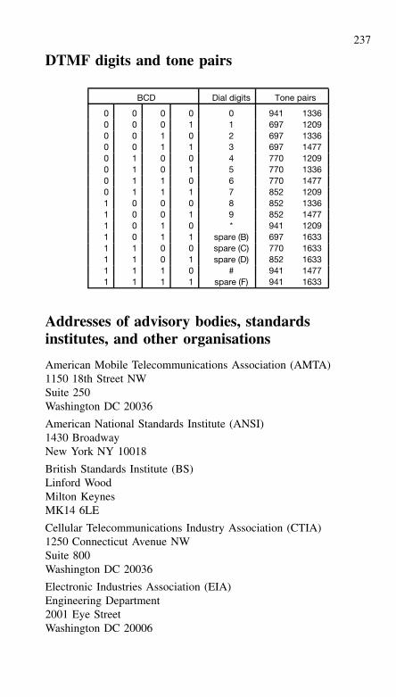
237
DTMF digits and tone pairs
BCD Dial digits Tone pairs
0 0 0 0 0 941 13360 0 0 1 1 697 12090 0 1 0 2 697 13360 0 1 1 3 697 14770 1 0 0 4 770 12090 1 0 1 5 770 13360 1 1 0 6 770 14770 1 1 1 7 852 12091 0 0 0 8 852 13361 0 0 1 9 852 14771 0 1 0 * 941 12091 0 1 1 spare (B) 697 16331 1 0 0 spare (C) 770 16331 1 0 1 spare (D) 852 16331 1 1 0 # 941 14771 1 1 1 spare (F) 941 1633
Addresses of advisory bodies, standardsinstitutes, and other organisations
American Mobile Telecommunications Association (AMTA)1150 18th Street NWSuite 250Washington DC 20036
American National Standards Institute (ANSI)1430 BroadwayNew York NY 10018
British Standards Institute (BS)Linford WoodMilton KeynesMK14 6LE
Cellular Telecommunications Industry Association (CTIA)1250 Connecticut Avenue NWSuite 800Washington DC 20036
Electronic Industries Association (EIA)Engineering Department2001 Eye StreetWashington DC 20006

238
European Computer Manufacturers Association (ECMA)11 Rue de RhoneCH-1204 GenevaSwitzerland
Federal Communications Commission (FCC)1919 M Street NWWashington DC 20554
IEEE Communications Society (ComSoc)305 East 47th StreetNew York NY 10017
IEEE Computer Society1109 Spring StreetSuite 300Silver SpringMD 20910
IEEE Standards Board345 East 47th StreetNew York 10017
Information Technology Standards UnitDepartment of Trade and Industry29 Bressenden PlaceLondonSW1E 5DT
Institute of Electrical and Electronics Engineers (IEEE)Three Park Avenue 17th FloorNew York NY 10016 5997
Institute of Electrical Engineers (IEE)Savoy PlaceLondonWC2R OBL
International Standards Organisation (ISO)1 Rue de VarembeCH-1211GenevaSwitzerland
International Telecommunications Union (ITU)Place des Nations1121 Geneva 2Switzerland

239
ITU-TPlace des NationsCH-1211 Geneva 20Switzerland
National Bureau of Standards (NBS)Technical Information and Publications DivisionWashington DC 20234
National Cable Television Association (NCTA)1724 Massachusetts Avenue NWWashington DC 20036
National Computing Centre (NCC)Oxford RoadManchesterM1 7ED
Personal Communications Industry Association (PCIA)500 Montgomery StreetSuite 700Alexandria VA 22314
Telecommunications Industry Association (TIA)2500 Wilson Boulevard Suite 300Arlington VA 22201-3834
US Department of CommerceNational Technical Information Service5285 Port Royal RoadSpringfieldVA 22161
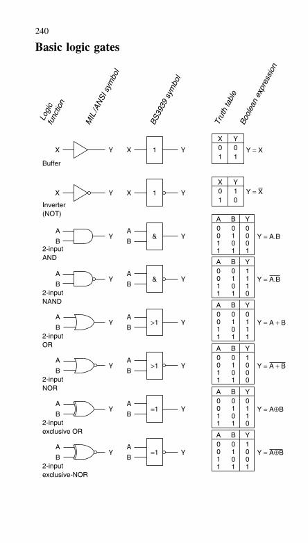
240
Basic logic gates
YX1001
Y
YXYX
Buffer
Inverter(NOT)
1
YXYX 1
X0011
Y = X
Y = X
A B Y
2-inputAND
YA
B
A
BY & Y = A.B
0 0 00 1 01 0 01 1 1
2-inputNAND
A B Y
YA
B
A
BY & Y = A.B
0 0 10 1 11 0 11 1 0
2-inputOR
A B Y
YA
B
A
BY >1 Y = A + B
0 0 00 1 11 0 11 1 1
2-inputNOR
A B Y
YA
B
A
BY >1 Y = A + B
0 0 10 1 01 0 01 1 0
2-inputexclusive OR
A B Y
YA
B
A
BY =1 Y = A⊕B
0 0 00 1 11 0 11 1 0
2-inputexclusive-NOR
A B Y
YA
B
A
BY =1 Y = A⊕B
0 0 10 1 01 0 01 1 1
Logi
cfu
nctio
n
MIL
/AN
SI s
ymbo
l
BS39
39 s
ymbo
l
Trut
h ta
ble
Bool
ean
expr
essi
on
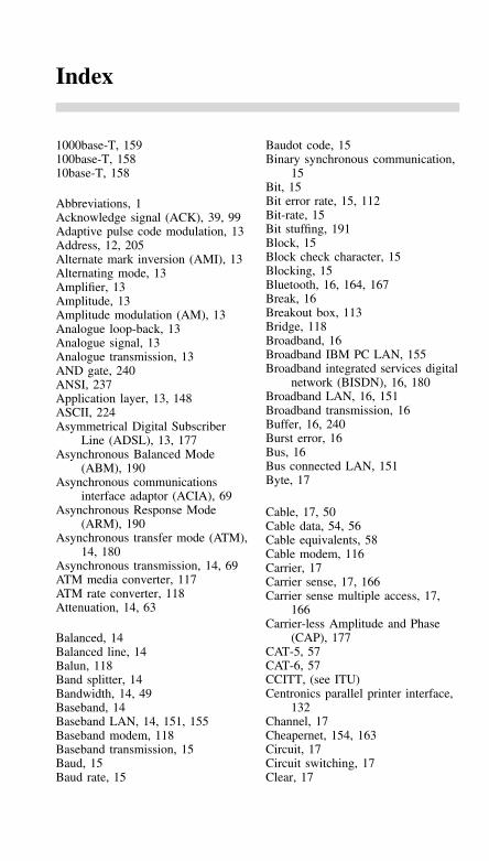
Index
1000base-T, 159100base-T, 15810base-T, 158
Abbreviations, 1Acknowledge signal (ACK), 39, 99Adaptive pulse code modulation, 13Address, 12, 205Alternate mark inversion (AMI), 13Alternating mode, 13Amplifier, 13Amplitude, 13Amplitude modulation (AM), 13Analogue loop-back, 13Analogue signal, 13Analogue transmission, 13AND gate, 240ANSI, 237Application layer, 13, 148ASCII, 224Asymmetrical Digital Subscriber
Line (ADSL), 13, 177Asynchronous Balanced Mode
(ABM), 190Asynchronous communications
interface adaptor (ACIA), 69Asynchronous Response Mode
(ARM), 190Asynchronous transfer mode (ATM),
14, 180Asynchronous transmission, 14, 69ATM media converter, 117ATM rate converter, 118Attenuation, 14, 63
Balanced, 14Balanced line, 14Balun, 118Band splitter, 14Bandwidth, 14, 49Baseband, 14Baseband LAN, 14, 151, 155Baseband modem, 118Baseband transmission, 15Baud, 15Baud rate, 15
Baudot code, 15Binary synchronous communication,
15Bit, 15Bit error rate, 15, 112Bit-rate, 15Bit stuffing, 191Block, 15Block check character, 15Blocking, 15Bluetooth, 16, 164, 167Break, 16Breakout box, 113Bridge, 118Broadband, 16Broadband IBM PC LAN, 155Broadband integrated services digital
network (BISDN), 16, 180Broadband LAN, 16, 151Broadband transmission, 16Buffer, 16, 240Burst error, 16Bus, 16Bus connected LAN, 151Byte, 17
Cable, 17, 50Cable data, 54, 56Cable equivalents, 58Cable modem, 116Carrier, 17Carrier sense, 17, 166Carrier sense multiple access, 17,
166Carrier-less Amplitude and Phase
(CAP), 177CAT-5, 57CAT-6, 57CCITT, (see ITU)Centronics parallel printer interface,
132Channel, 17Cheapernet, 154, 163Circuit, 17Circuit switching, 17Clear, 17
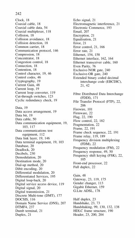
242
Clock, 18Coaxial cable, 18Coaxial cable data, 54Coaxial multiplexer, 118Collision, 18Collision avoidance, 18Collision detection, 18Common carrier, 18Communication protocol, 146Compression, 18Concentrator, 18Congestion control, 18Connection, 18Contention, 18Control character, 19, 46Control codes, 46Cryptography, 19Current Gain, 48Current loop, 19Current loop converter, 119Cut-through switches, 123Cyclic redundancy check, 19
Data, 19Data access arrangement, 19Data bit, 19Data cable, 50Data communication equipment, 19,
103, 117Data communications test
equipment, 112Data link layer, 19, 146Data terminal equipment, 19, 103Database, 20Deadlock, 20Decibels, 230Demodulation, 20Destination mode, 20Dial-up method, 20Dibit encoding, 20Differential modulation, 20Differentiated Services, 195Digital loop-back, 20Digital service access device, 119Digital signal, 20Digital transmission, 21Discrete Multi-tone (DMT), 177DOCSIS, 116Domain Name Service (DNS), 207DTMF4, 237Dumb terminal, 21Duplex, 21
Echo signal, 21Electromagnetic interference, 21Electronic Commerce, 193Email, 207Encryption, 21Equalisation, 21Error, 21Error control, 21, 166Error rate, 21Ethernet, 154, 158Ethernet interface, 162, 164Ethernet transceiver cable, 160Even Parity, 76Exclusive-NOR gate, 240Exclusive-OR gate, 240Extended binary coded decimal
interchange code (EBCDIC),21, 42
Fibre Distributed Data Interchange(FDDI), 171
File Transfer Protocol (FTP), 22,206
Firewire, 101Firmware, 22Flag, 22, 190Flow control, 22, 182Fragmentation, 22Frame, 22, 191Frame check sequence, 22, 191Frame relay, 119, 189Frequency division multiplexing
(FDM), 22Frequency modulation (FM), 22Frequency response, 49, 50Frequency shift keying (FSK), 22,
105Front-end processor, 22Full duplex, 22
Gain, 48Gateway, 23, 119, 175Gender changer, 113Gigabit Ethernet, 159G.Lite ADSL, 178
Half duplex, 23Handshake, 23, 73Handshaking, 99, 130, 132, 138HDLC frame structure, 190Header, 23, 200, 204
243
Hierarchical network, 23High state, 23High-level Data Link Control
(HDLC), 23, 190High-speed Digital Subscriber Line
(HDSL), 176, 179HiperLAN, 164, 169Host computer, 23Host to host protocol, 23Hub, 120
ICL Macrolan, 156ICMP, 210IEE, 238IEEE, 238IEEE-488, 134IEEE-488 bus configuration, 140IEEE-488 command codes, 139IEEE-488 commands, 138IEEE-488 connector, 137IEEE-488 Programming, 143IEEE-488 signals, 136IEEE-488 software, 141IEEE-802, 152, 164, 169IEEE-1355, 101IEEE-1394 (Firewire) 101Impedance, 23In-band control, 23In-band signalling, 24Industrial, Scientific and Medical
(ISM) band, 167Information bit, 24Information frame, 24Infra Red, 170Input impedance, 49Input/output port, 24Integrated services digital network
(ISDN), 24, 175Interface, 24, 72Interface converter, 120Interface system, 24Interface tester, 113International alphabet no. 2, 38International alphabet no. 5, 39International Telecommunications
Union (ITU), 212, 238Internet address, 24Internet Protocol, 198Internetworking, 24Inverse multiplexer, 120Inverter, 240IPv4, 199
IPv6, 204ISO, 146ISO model for OSI, 146Isochronous, 24ITU, 212, 238ITU-T G-series, 212ITU-T I-series, 214ITU-T V-series, 216ITU-T X-series, 219
Java, 194
Keyboard, 43Keyboard entry, 46Keyboard Control Characters, 46
LAN (Local Area Network), 25, 149LAN manager, 120LAN Security, 192LAN selection, 153LAN software, 192LAN topology, 149Light Propagation, 60Line driver, 25Line monitor, 113Line receiver, 25Line termination unit, 121Line turn-around, 25Link, 25Listen-before-talking, 25Listen-while-talking, 25Loaded line, 25Local area network, 25, 149Local loop, 25Longitudinal redundancy check, 25Loop-back, 26Loss, 48Low state, 26
Manufacturing Automation Protocol,156
Mark, 26Media access control, 165Medium range modem, 121Memory, 26Message switching, 26Microwave link, 26Modem, 26, 105Modulation, 26Mono-mode fibre, 64Multi-drop link, 26
244
Multi-meter, 114Multi-mode fibre, 64Multi-Protocol label switching
(MPLS), 209Multiple access, 26Multiplexer, 26, 121, 176Multiplexing, 27Multi-point link, 26
Negative acknowledge (NAK), 99NAND gate, 240Network, 27Network File Server, 27Network layer, 27, 146Network management system, 27Network Operating System, 196Network protocol, 198NFS, 210Node, 27Noise, 27NOT gate, 240Null modem, 27, 104, 113
Octet, 27Odd Parity, 76Open data link interface, 28Open system interconnection, 28Operating system, 28Optical cable, 59Optical detector, 66Optical fibre, 28, 59Optical fibre connectors, 65Optical safety, 67Optical sources, 66OR gate, 240Oscilloscope, 114OSI, 181Out of band control, 28Output impedance, 49
Pacing, 28Packet, 28, 69, 149Packet assembler/dis-assembler, 28,
119Packet switched data network, 28,
189Packet switching, 28Packet switching access unit, 121Parallel I/O, 70, 130Parallel printer interface, 132Parallel transmission, 28
Parity bit, 29, 76Parity check, 29Patch box, 112Peer entity, 29Peripheral, 29Personal Computer Keyboard, 43Phase modulation, 29, 105Phase shift, 49Physical layer, 29, 146Piggy-back, 29Ping, 99Pipelining, 29Polling, 29, 105Port, 30, 206Power, 230Power Gain, 48Powers of 16, 224Powers of 2, 230Presentation layer, 30, 148Private line, 30Propagation delay, 30Protocol, 30, 146Pulse code modulation (PCM), 30
Quadrature amplitude modulation(QAM), 105
Qualified data, 30Quality of Service (QoS), 195Query, 30Queue, 30
Rate converter, 122Receiver, 30Redundancy check, 30Remote Procedure Call, 30, 210Repeater, 30, 122Residual error rate, 30Reverse channel, 31Ring connected LAN, 150Ring network, 31RJ-11 interface connections, 94RJ-12 interface connections, 95RJ-45 interface connections, 96Router, 31, 122Routing, 31, 209RS-232, 72RS-232 data cables, 80RS-232 electrical specifications, 77RS-232 enhancements, 84RS-232 fault finding, 114RS-232 interchange circuits, 103RS-232 interface, 79
245
RS-232 interface connections, 82RS-232 logic levels, 78RS-232 Null Modem, 104RS-232 pin connections, 74RS-232 signals, 73, 77RS-232 voltage levels, 78RS-232 waveforms, 76RS-422, 84RS-422 logic levels, 85RS-422 voltage levels, 85RS-423, 85RS-423 logic levels, 86RS-423 voltage levels, 86RS-449, 86RS-449 interchange circuits, 87RS-449 interface connections, 89RS-449 pin connections, 88RS-485, 90RS-530 interface connections, 91RSVP, 210
Scroll mode terminal, 31SDSL, 178Serial I/O, 69Serial transmission, 31, 68Session layer, 31, 147Sideband, 31Signal, 31Signal level, 31Signal parameter, 31Simple Mail Transfer Protocol
(SMTP), 207Simple Network Management
Protocol (SNMP), 210Simplex, 32Sliding window, 32Socket, 32Source node, 32Source routing, 32SPACE, 32Star connected LAN, 150Start bit, 32, 76Start-stop signalling, 32Statistical multiplexer, 32Stop and wait protocol, 32Stop bit, 32, 76Store and forward, 32, 123Supervisory frame, 32Switches, 122Switching, 33Synchronisation, 33
Synchronous data link control, 33Synchronous transmission, 33, 69
Tandem, 33TCP/IP, 209Technical and Office Protocol, 156Teletype keyboard, 37Telnet, 206Terminal control codes, 43Terminal server, 33Time division multiplexing (TDM),
33, 166Time-to-live, 202Timeout, 33Time-sharing, 33Token, 33, 172Token ring LAN, 155Topology, 34Traffic analysis, 34Transceiver, 34Transmission element, 48, 50Transmission line power, 48, 235Transmitter, 34Transparency, 34Transport layer, 34, 147Transport Protocol, 205Tribit encoding, 34Trunk, 34Twisted Pair Ethernet, 158
Unbalanced line, 34Universal Asynchronous
Receiver/Transmitter (UART),69
Universal Serial Bus (USB), 97, 117Unnumbered frame, 34User Datagram Protocol (UDP), 198
V.21, 105, 110V.22, 105, 110V.24 (RS232), 68V.26A, 106, 111V.26B, 106, 111V.26bis, 111V.27, 106V.34, 106, 110V.35 interface connections, 93V.90, 106V.92, 106Vertical redundancy check, 34
246
Very High Speed Digital SubscriberLine (VDSL), 179
Virtual circuit, 35Virtual private network (VPN), 193Voice-grade line, 35Voice over IP, 194Voltage Gain, 48VT-100, 44VT-52, 44
Wide area network (WAN), 35, 175Wideband, 35Wireless Application Protocol
(WAP), 208Wireless LAN, 164
Workstation, 35World wide web (WWW), 208Wyse-100, 45
X.21 interface connections, 92X.25, 186X.25 control packet format, 188X.25 packet format, 188XMODEM, 182XMODEM/CRC protocol, 185X-ON/X-OFF, 106, 182
YMODEM, 182
Zero insertion, 35