Embed Size (px)
Citation preview
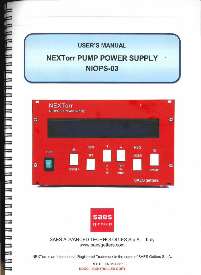
USER'S MANUAL
NEXTorr PUMP POWER SUPPLY NIOPS-03
SAES ADVANCED TECHNOLOGIES S.p.A. - Italy www.saesgetters.com
NEXTorr is an International Registered Trademark in the name of SAES Getters S.p.A.
M.HIST.0058.23 Rev.3
UDOC - CONTROLLED COPY
The NEXTorr NIOPS-03 power supply serves for operating the NEXTorr D 100-5 and NEXTorr 0200-5 pumps. It is designed to be used indoor in laboratory conditions.
WARNING
After transportation, the device has to be left idle without ' mains voltage for at least 3 hours at the laboratory
Security provisions
ATTENTION
Inside the instrument and also in the connector and cable for the ion pump connection, a high voltage is present which is capable of causing a casualty even without any direct touch.
Manipulation the high voltage cable and also of the grounding wire is prohibited during the course of the supply operation.
Likewise, the supply operation without protective covers is prohibited.
Protect the device against humidity and against penetration of conductive objects and liquids into the ventilation slots.
Symbols on the Product
These symbols appear on the product:
Lt,
WARNING High voltage
J_
Ground terminal
Lt CAUTION Refer to manual
POWER SUPPLY NIOPS-03 - USER'S MANUAL M.HIST.0058.23 Rev.3 Page 2 of 42
The NEXTorr NIOPS-03 power supply serves for operating the NEXTorr D 100-5 and NEXTorr 0200-5 pumps. It is designed to be used indoor in laboratory conditions.
WARNING
After transportation, the device has to be left idle without mains voltage for at least 3 hours at the laboratory
Security provisions
ATTENTION
Inside the instrument and also in the connector and cable for the ion pump connection, a high voltage is present which is capable of causing a casualty even without any direct touch.
Manipulation the high voltage cable and also of the grounding wire is prohibited during the course of the supply operation.
Likewise, the supply operation without protective covers is prohibited.
Protect the device against humidity and against penetration of conductive objects and liquids into the ventilation slots.
Symbols on the Product
These symbols appear on the product:
Lt WARNING
High voltage Ground terminal
& CAUTION Refer to manual
POWER SUPPLY NIOPS-03 - USER'S MANUAL M.HIST.0058.23 Rev.3 Page 2 of 42
INDEX
1. APPLICATION ......................................................................................... 5
2. INTRODUCTION ..................................................................................... 5
2.1. General description ...................................... ~ .................................... 5
2.2. Simplified block scheme ·······:······ ...................................................... 6
2.3. Scheme connections Instrument.. ..................................................... 6
2.4. The front panel of the unit ................................................................. 7
2.5. The rear panel of the unit. ................................................................. 8
2.6. Instrument Dimensions ..................................................................... 9
3. INSTALLATION ..................................................................................... 10
3.1. Mounting operation ......................................................................... 10
3.2. Electrical connections ..................................................................... 11
4. OPERATIONS ....................................................................................... 12
4.1. Start operations ............................................................................... 12
4.2. Operating IP supply ........................................................................ 12
4.3. Operating NP supply ....................................................................... 13
4.4. Operating IP and NP supply in case of line interruption ................. 14
5. CHANGE OF IP SETTINGS .................................................................. 15
6. SERVICE MODE IP ............................................................................... 16
7. SERVICE MODE NP ............................................................................. 17
8. THE OUTPUT CONNECTOR FUNCTION ............................................ 18
8.1. IN/OUT Interface ............................................................................. 18
8.2. Analog Output ................................................................................. 20
8.3. RS232/485 Interface ....................................................................... 21
9. CONTROL VIA A SERIAL CHANNEL ................................................... 22
9.1. Definition ......................................................................................... 22
9.2. Communication protocol for RS232 ................................................ 22
9.3. The transmission protocol. .............................................................. 23
9.4. Service of failures ........................................................................... 23
9.5. The commands used ...................................................................... 24
9.6. Communication protocol for RS485 MODBUS RTU ....................... 29
10. MAINTENANCE AND TROUBLESHOOTING ...................................... 33
POWER SUPPLY NIOPS-03 - USER'S MANUAL M.HIST.0058.23 Rev.3 Page 3 of 42
10.1. NP troubleshooting ....................................................................... 33
10.2. IP troubleshooting ........................................................................ 34
11. SPECIFICATIONS ................................................................................ 36
12. INSTRUCTION FOR INSTRUMENT DISPOSAL ................................. 37
13. PRODUCT CONFIGURATIONS AND ACCESSORIES ....................... 38
14. WARRANTY CONDITIONS ........................................................ : ......... 39
15. SERVICE .............................................................................................. 40
15.1. Sales & Service Locations: .......................................................... 40
POWER SUPPLY NIOPS-03 - USER'S MANUAL M.HIST.0058.23 Rev.3 Page 4 of 42
1. APPLICATION
The NEXTorr power supply, model NIOPS-03, is designed for operating the NEXTorr D 100-5 and NEXTorr D 200-5 pumps.
2. INTRODUCTION
2.1. General description
The device consists of two power units incorporated in one frame. The former power unit controls the ion pump (IP), while the latter is designed for non evaporable getter pump (NP). Both units utilize mutual line power module and they are controlled by a microprocessor circuit.
The IP supply unit is based on a "flyback" type voltage converter, which works at 20 kHz frequency. The converter operation principle, in combination with the circuit configuration of the power supply, produces V-A characteristics suitable to operate the ion getter pumps.
The NP supply unit is a voltage controlled power supply designed to operate at low resistance loads. The supply is based on forward switching convertor to which are added measuring and protective circuits.
Both supplies are controlled by a microprocessor unit which enables to set working mode, measure output current and power, protect supply against overheat, short and open circuit, display parameters and communicate with external facilities via serial channel.
The two power units can operate independently. In some case the NP and IP can operate coupled in safety condition.
Most of functions and parameters can be controlled and read via serial communication protocol RS232 ASCII or RS485 MODBUS RTU.
POWER SUPPLY NIOPS-03 - USER'S MANUAL M.HIST.0058.23 Rev.3 Page 5 of 42
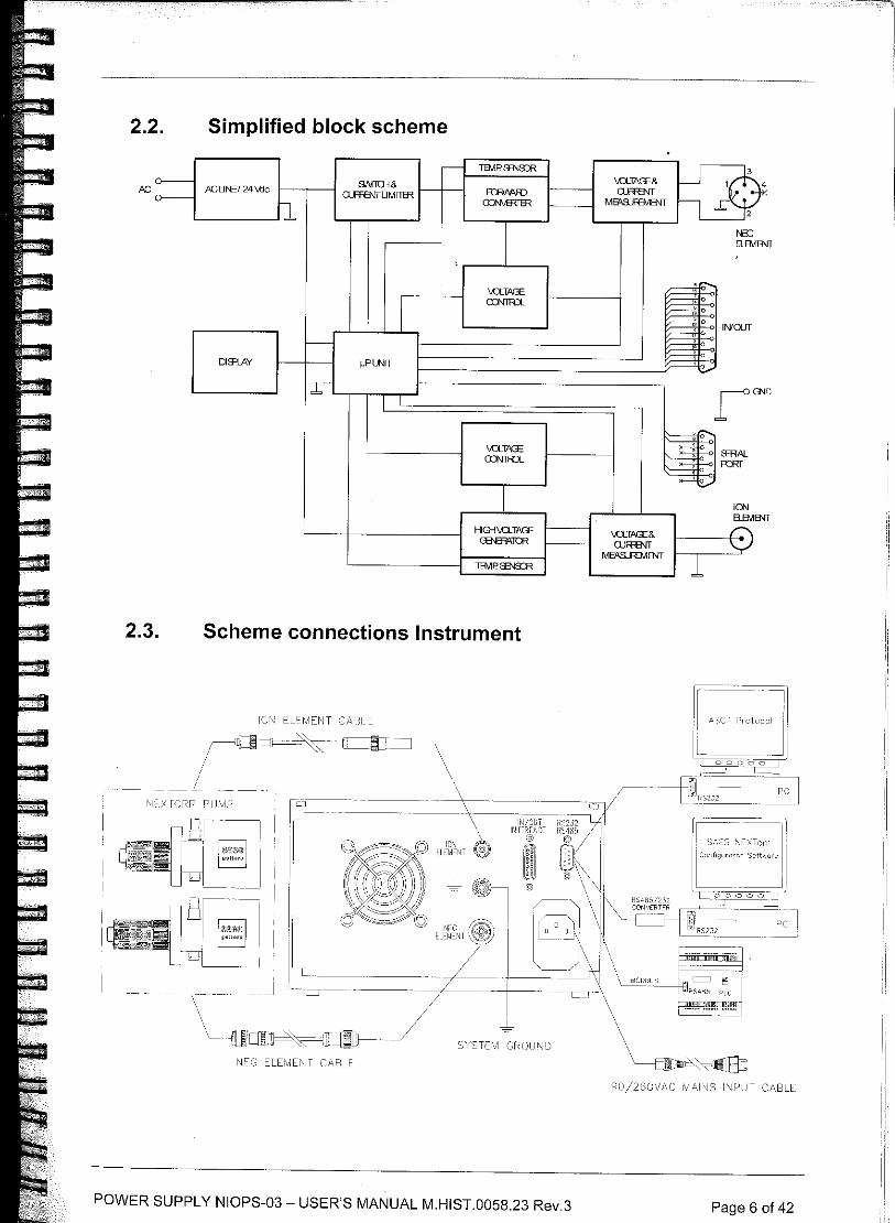
2.2. Simplified block scheme
~ TBvlP. 93\Js:R u9 0---- 91\fllli& \O...TAGE& ACLJNE/ 24 \.tic FffiMR) Q,ffiNf
0---- OJFR3\!TLJMITffi =-iER M6"SJRMENT h 2 11
>133 ELB\11 ENT
'
\Ul>l:E
l CXNllU " " " INIOJr '
f-- ' " 0
Dim.AV µPl.NIT ' ~
1~ rG< L c
\Ul>l:E :dE- S'HAL CXNllU -;;:: ~ =
~ rn ELB\11 ENT
HIG-1\..a...TACE \Ul>l:E& B ~lffi UJFHNT M6"SJRMENT
I TBVlP. 93\Js:R
2.3. Scheme connections Instrument
l\J~G ELElv1Ei\JT C,L\B~t
90/260\11\C ~;IP,INS ll\!l-'LJT C/\BU:
POWER SUPPLY NIOPS-03 - USER'S MANUAL M.HIST.0058.23 Rev.3 Page 6 of 42
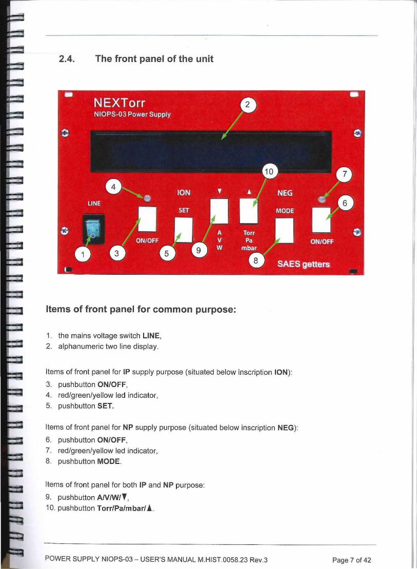
2.4. The front panel of the unit
Items of front panel for common purpose:
1. the mains voltage switch LINE,
2. alphanumeric two line display.
Items of front panel for IP supply purpose (situated below inscription ION):
3. pushbutton ON/OFF,
4. red/green/yellow led indicator,
5. pushbutton SET.
Items of front panel for NP supply purpose (situated below inscription NEG):
6. pushbutton ON/OFF,
7. red/green/yellow led indicator,
8. pushbutton MODE.
Items of front panel for both IP and NP purpose:
9. pushbutton AN/W/,, 10. pushbutton Torr/Pa/mbar/ .!.
POWER SUPPLY NIOPS-03 - USER'S MANUAL M.HIST.0058.23 Rev.3 Page 7 of 42
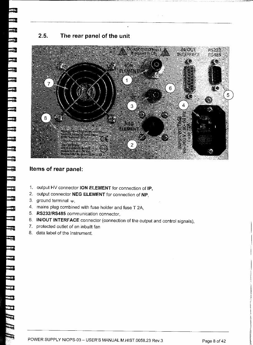
2.5. The rear panel of the unit
Items of rear panel:
1. output HV connector JON ELEMENT for connection of IP,
2. output connector NEG ELEMENT for connection of NP, 3. ground terminal .,!,.,
4. mains plug combined with fuse holder and fuse T 2A,
5. RS232/RS485 communication connector,
6. IN/OUT INTERFACE connector (connection of the output and control signals), 7. protected outlet of an inbuilt fan
8. data label of the instrument.
POWER SUPPLY NIOPS-03 - USER'S MANUAL M.HIST.0058.23 Rev.3 Page 8 of 42
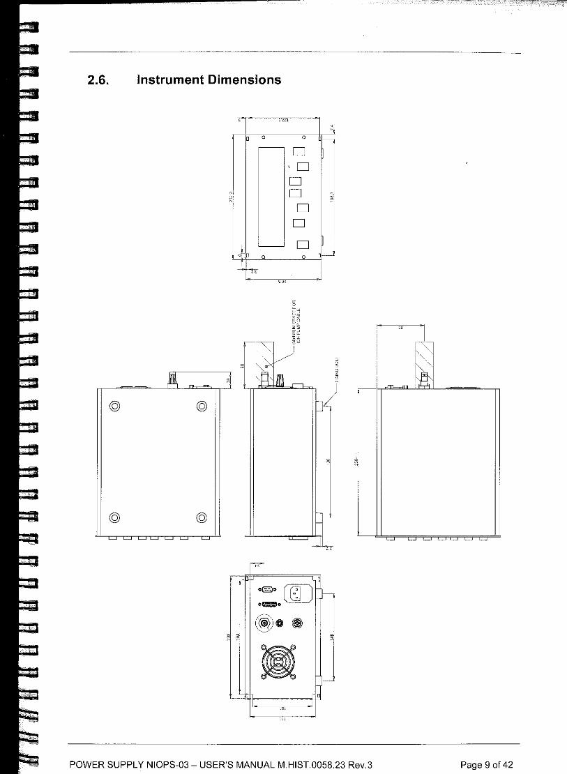
2.6. Instrument Dimensions
© ©
© ©
D"
"'
o D
D ·D D D
D D
D 0
POWER SUPPLY NIOPS-03 - USER'S MANUAL M"HIST"005823 Rev"3 Page 9 of 42
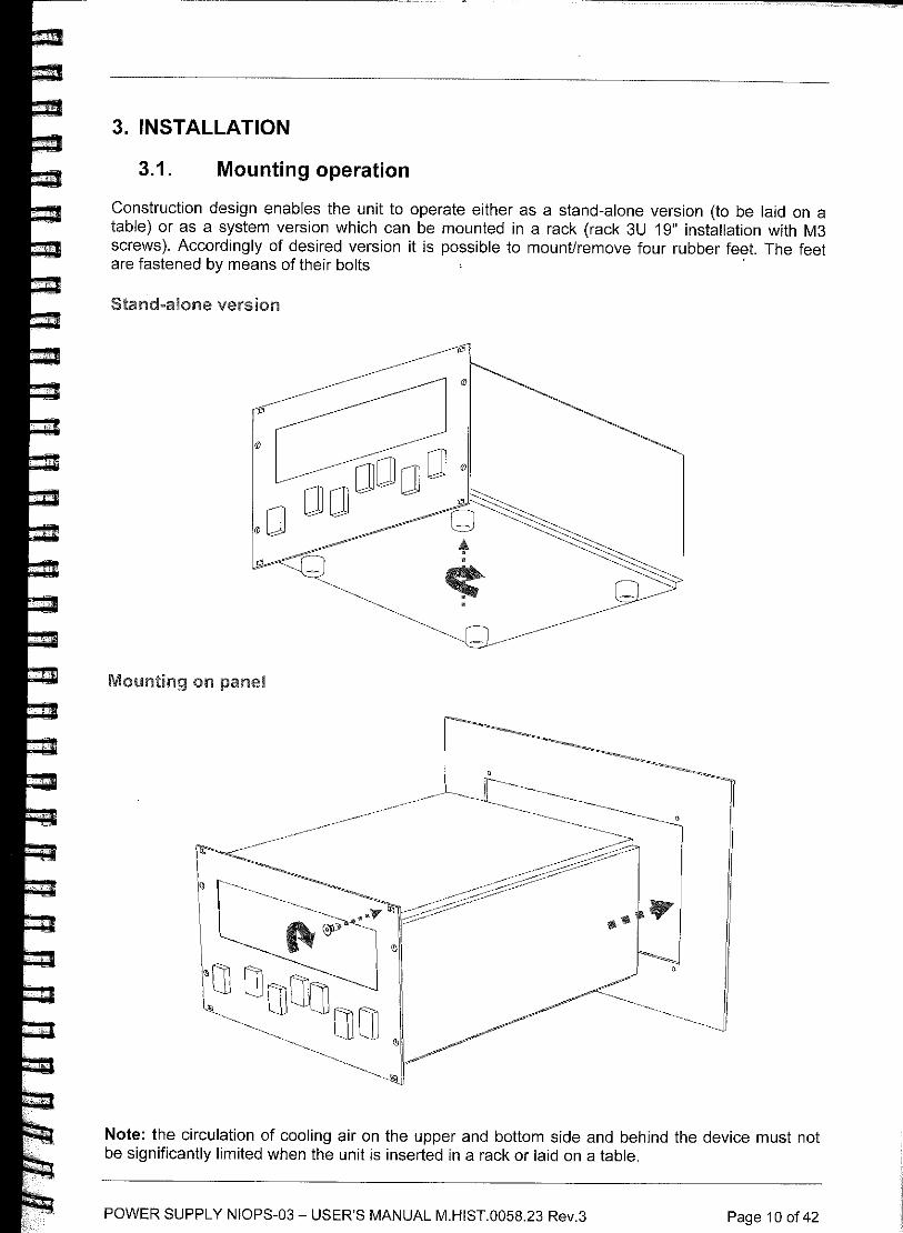
3. INSTALLATION
3.1. Mounting operation
Construction design enables the unit to operate either as a stand-alone version (to be laid on a table) or as a system version which can be mounted in a rack (rack 3U 19" installation with M3 screws). Accordingly of desired version it is possible to mount/remove four rubber feet. The feet are fastened by means of their bolts '
Stand-alone version
Mounting on panel
Note: the circulation of cooling air on the upper and bottom side and behind the device must not be significantly limited when the unit is inserted in a rack or laid on a table.
POWER SUPPLY NIOPS-03 - USER'S MANUAL M.HIST.0058.23 Rev.3 Page 10 of42
3.2. Electrical connections
The IP is connected to the power supply by means of the provided high voltage cable. The appropriate cable terminal is inserted into the high voltage connector labeled ION ELEMENT. The cable is locked by rotating the ring against spontaneous disengagement. The same operation must be done for the opposite end of the cable on the pump side. When connecting, it is necessary to check carefully whether a reliable contact is secured between the frame of the pump[ng system and the outer electrode of the high voltage connector (by means of the screening braid of the high voltage cable). For security reasons it is necessary to interconnect the pumping system frame with the supply ground terminal -4. by using a protective cable. The protective coupling must be done by a conductor with a cross-sectional area of min. 0. 75 mm2 and maximum length of 20 m.
The protective mains wire and the ground terminal -4. or the outer electrode of the high voltage connector are not mutually galvanically interconnected. They are separated by means of protective diodes which become conductive if the voltage between the protective wire and the -4. terminal exceeds 0. 7 V.
The NP is connected to the power supply unit by the 3-wire cable provided, inserting it in the NEG ELEMENT connector. Connectors on both sides of the cable must be locked against spontaneous disengagement by rotating their rings.
The enclosed plug DB 15 (Interlock) with junctions (shorted pins 6-9 and 1-14) should be inserted to connector IN/OUT on the rear panel or the junctions may be replaced by a suitable system of safety switching off (see Sec. 8).
&warning Connection and disconnection of the high voltage cable are possible only with the power supply switched off.
POWER SUPPLY NIOPS-03 - USER'S MANUAL M.HIST 0058.23 Rev.3 Page 11 of 42
4. OPERATIONS
4.1. Start operations
The supply is switched on by pressing the LINE switch into position I; the connection is signaled by the green light of the switch. The IP and NP are not electrically powered (see Sec. 4.2 and 4.3 for the operating conditions).
The messages Wait ... on first line and NEXTorr 0100-5 or NEXTorr 0200-5 on second line are displayed during device initiation for a short time. During this time the NP outer electrical circuit is tested. The message on the second line show the NEXTorr pump selected. To change the selection, see Sec. 7.
If the interlock plug is not inserted or some of the junctions are interrupted, the display will show the message Disabled! on both lines of the display (see Sec. 8.1).
When the initiation process is successfully over the display will show on the first line an message: I Ready ... and on the second line: N Ready ... Mode?.
The both indicators above ON/OFF pushbuttons will light red (providing the previous state before the line was switched off had been OFF).
If the outer circuit of NP is not all right, the display shows Open! (for interrupted circuit) or Short! (for short circuit between heating element of NEG and frame). These messages will appear with a delay of several seconds and the indicator in NEG section will start blinking yellow.
The first line of the display starts with letter I and is devoted to the states and parameters of IP supply. The second line starting with letter N will show states and parameters of NP supply.
4.2. Operating IP supply
The IP supply can be switched on by pressing the pushbutton ON/OFF in the section ION. The unit must be switched on only at the recommended starting pressure (see pumps Operating Instruction Manual for details). The working state of the supply is indicated by green light led above the mentioned pushbutton.
The current flowing through the pump can be read from the front panel display. Sometime after switching-on the IP supply unit, a character in the form ,J. or t may appear on the left hand side of the display. This symbol expresses a systematic trend (approx. during last 30 to 45 s) in the pump current variation - increasing or decreasing. If no arrow is displayed, it means that the current is more or less stable. The pump voltage, output power and pump current can be alternatively displayed by pushing the pushbutton AN/W.
Pushing the button Torr/Pa/mbar will sequentially display the pump pressure value in this units. The relationship between the value of the current and pressure is dependent on the type and size of used pump. To set the values see Sec. 5. The relationship between current and pressure may be dependent also of the instantaneous pump voltage. It is noteworthy that the pressure value calculated from the pump current value has to be considered as rough indication (especially at very low pressure when a leakage pump current may occur). An *(asterisk) shows up when IP current reaches 0 nA (IP current is below the measurable limit).
Lt warning
In the case the HV cable is disconnected, the current will be 0 and the asterisk will show up as well.
The device is equipped with an automatic overcurrent protection which switches off the IP supply (the high-voltage part) after the pump current exceeds the safety value protection adjusted under 1 H (see Sec. 5), which is indicated by yellow blinking of the indicator above ON/OFF pushbutton.
POWER SUPPLY NIOPS-03 - USER'S MANUAL M.HIST.0058.23 Rev.3 Page 12 of 42
At the same time an acoustic signal and the word Overload will appear on the display. After 3+5 seconds the supply automatically switches on again. If the overcurrent protection level is exceeded once again, the device switches off repeatedly. After 3 unsuccessful attempts to switch on the supply automatically, the supply switches off permanently and the yellow blinking indicator and acoustic signal sound do not stop. To switch-on the IP supply unit, press down on the ON/OFF button. The ON/OFF button must be held pressed until the current decreases below the current level set in 1 H.
If the pump current at repeated attempts to switch on reaches 90 mA value the supply remains permanently switched off and the sign Error! will.appear on the display. The only possible exit from this state is to switch off the whole unit from the mains switch LINE. After the cause of excessive current is removed (e.g. getting a better vacuum or removing a short circuit) it is possible to switch on the unit again.
These functions protect the supply against an excessive load but also protect your pump against an uncontrolled operation, which could damage it or shorten its lifetime.
The supply is equipped with three comparators-switches of the pump current/pressure. The function of the first one, labeled 1, was described in the previous paragraph. The other two, 2 and 3, serve for the needs of customers who are not going to use a computer to control the pumping process or it is possible to incorporate their outputs to hardware system of related appliances. Their outputs are led to the IN/OUT output connector and the characters depicted on the last two positions of the display first line simultaneously indicate their function. The L letter lights up when the pump current/pressure is lower than the adjusted values while the H letter lights up if the current/pressure exceeds the pre-set value. Comparators-switches 2 and 3 can work in Simple regime or in Window regime. To change regime see Sec. 5.
Simple regime If the current/pressure is between preset L and H values, the state of the indicator and output switch of related comparator depends on the sense of current/pressure change. The L symbols and closed contacts on output connector will stay unchanged until current/pressure value exceeds H value and H symbols and unclosed contacts will stay unchanged until current/pressure value goes under preset L value. The hysteresis switching on I off is given by adjusted values L and H.
Window regime If the current/pressure is between L and H values, the indicators of related comparator will show letter W. The output of the comparator is composed by a pair of contacts which are disconnected if the current/pressure is lower than preset level L or is higher than preset level H. Inside the interval L-H the output contacts are connected. The hysteresis of switching on when current/pressure is increasing over the level L is automatically set to a value by 10 % higher and when decreasing below value H by 10 % lower level. This circumstance must be taken into consideration when setting levels L and H.
The pin layout of the output connector is described in the Sec. 8.
Note: When the current range in the instrument is changed with the upper value of 1 mA or 10 µA, the function of output switches is delayed by several seconds.
4.3. Operating NP supply
The message Ready ... Mode? on the second line of the display appears if the NP is properly connected. From this point on, it is possible to choose one of four working modes by pressing the pushbutton MODE:
• Activation: NEXTorr 0100-5 - the supply delivers 9 V/ 5 A continuously and full power 45 W NEXTorr 0200-5 - the supply delivers 12,5 V/ 4,8 A continuously and full power 60 W
POWER SUPPLY NIOPS-03 - USER'S MANUAL M.HIST 0058.23 Rev.3 Page 13 of 42
• Tmd Activation - (timed activation): NEXTorr 0100-5 - the supply delivers 9 V/ 5 A and full power 45 W for 1 hour NEXTorr 0200-5 - the supply delivers 12,5 V/ 4,8 A and full power 60 W for 1 hour
• Conditioning: NEXTorr 0100-5 - the supply delivers approx. 4.5 V and 25 % of full power NEXTorr 0200-5 - the supply delivers approx. 6 V and 25 % of full power
• Tmd Conditioning - (timed conditioning): NEXTorr 0100-5 - the supply delivers approx. 4.5 V and 25 % of full power for 1 hour NEXTorr 0200-5 - the supply delivers approx. 6 V and 25 % of full power for 1 hour
Each chosen mode can be started by pressing ON/OFF pushbutton in NEG section and interrupted again by pressing ON/OFF pushbutton. The output voltage after start rises slowly to prevent inrush current to cold heating element. Timed modes are automatically ended after 1 hour.
When the supply unit is operating (after ON/OFF pushbutton is pressed) the display shows an abbreviation of working mode, delivered power, elapsed time and count of failures:
• Act- stands for activation,
• TdAct- stands for timed activation,
• Con - stands for conditioning,
• TdCon - stands for limed conditioning.
The displayed value of delivered power is the power on input terminals of NP. This value of power is calculated, from the power measured on the output terminals of the supply (where voltage and current are measured) subtracted the voltage drop caused from the resistance of the cable. For this reason the power obtained as a product of voltage and current (see Sec. 7) is different from the displayed one. The above mentioned compensation is valid only for properly set cable length, when using another cable the accuracy reading of the power would be changed.
The last two positions of the display second line are devoted to failure counter. If a failure has occurred, a symbol of # following by number of failure would appear. When no failure was indicated, the mentioned two symbols stay blank. The failure counter increases only when the failure occurs during on-state.
4.4. Operating IP and NP supply in case of line interruption
Both power supplies can operate singly or together according to user's selection. In case of interruption of line voltage, and then after its restoration, both power supplies try to continue their previous activity. However, before the activity of NP is restored the vacuum condition in the chamber must be checked. For this purpose the IP is always switched on and after 40 seconds of activity the value of IP current is measured. The current value is compared with two preset values - Low curr and High curr. If the current value lies between the two preset limits, the NP power supply is switched on and the IP power supply is switched off (or it stays in on position to preserve the previous state). If this condition is not fulfilled both IP and NP power supplies will stay switched off and a message Bad Vacuum! will appear on second line of display. For setting Low and High current limit see Sec. 7.
Should the NP activity be interrupted by a lack of power, the operation state will not be lost. When the power is recovered, the IP and NP will automatically re-start from the last state before the failure. The automatic procedure is describes above.
If either NP or IP are not in working conditions, it is necessary to switch off them manually by means of ON/OFF pushbuttons.
POWER SUPPLY NIOPS-03 - USER'S MANUAL M.HIST.0058.23 Rev.3 Page 14 of 42
·1-...... -.·.!··· g; r !
5. CHANGE OF IP SETTINGS
The comparison level for the overcurrent protection circuits (1 H) and of the additional two comparators (2L, .. . 3H) have been introduced in Sec. 4.2. These and the final high voltage value are adjustable by the user according to his needs. To enable the changes of setting, the function must be unlocked (see Sec. 6). If frequent changes of setting are not assumed, it is advisable to lock the setting function to prevent an unintentional change.
After the SET key is pushed, the editable variables are displayed. Each of them is accompanied by the additional information: inscription Set, the label of comparison level (e.g. 1 H - 1st comparator, overcurrent level) and its value (with the measuring units). The pressure units are not displayed.
Providing it is necessary to change the value then press key i or l. Further pressing the SET key changes the set function to following levels of the comparators (2L, ... , 3H - 3rd comparator, high level). Maximal possible adjusted value of current is 89.9 mA. Minimum possible adjusted value is 5 nA. Returning to the measurement mode is possible either through a sequence of steps with the help of the SET key behind the last adjustable level or by leaving any value unchanged for longer than 5 seconds.
The adjustment of levels is possible in the pressure measurement regime too. Setting acts in those pressure units where the SET key was pushed.
The change of high voltage value is possible in voltage measurement regime. Press the SET key and then just press key i or l to arrange high voltage value. The range of adjustment is 1.2+6 kV with 50 V step. Return to the measurement mode is possible either by pressing SET key or by leaving set value unchanged for longer than 5 seconds.
Then the output voltage keeps this value with accuracy ±50 V providing that the output power does not overcome maximal possible value of the source.
Note:
The measurement of high voltage and derived output power only has an informative purpose. The voltage measurement error can reach up to 50 V. All pre-set values are stored even if the device is switched off.
POWER SUPPLY NIOPS-03 - USER'S MANUAL M.HIST.0058.23 Rev.3 Page 15 of 42
6. SERVICE MODE IP
The service mode gives useful information about the operation of the device and it enables the change of some working parameters.
The service mode is initiated by simultaneous pressing of pushbuttons A/VIW, Torr/Pa/mbar and with slight delay ON/OFF in ION section. A message Service mode will appear on the display. The following pressing of SET key will show on the display:
a) Worked out time of IP supply and NP supply.
b) Internal temperature of IP and NP power supply.
c) Magnitude of converting constant for recalculation from current to pressure. It is possible to change this constant by means of keys A or T in the range 20 to 4000 A/Torr. Resulting readings of pressure in different units will be influenced as well.
d) Contrast - contrast setting of the characters of the display. This constant can be set by means of keys A or T in the extent 0 to 255. The criterion of setting is a subjective judgment of contrast (standard value is 175).
e) Brightness - a constant expressing the brightness of indicators. This constant can be set by means of keys A or T in the extent 1 to 7. In this regime all indicators are alight. The criterion of setting is a subjective judgment of brightness (standard value is 3).
f) SW lock- lock of adjustment comparators-switches. The key A sets the state ON (locked), the key T sets the state OFF (unlocked) - it enables the adjustment of levels 1 H to 3H, output voltage U and working regime of comparators-switches 2 and 3.
g) SW2 W mode - switch of working regime of comparator-switch 2. The key A sets the state ON (Window regime), the key T sets the state OFF (Simple regime). To change this regime it is necessary to have set SW lock OFF according to the previous paragraph.
h) SW3 W mode - switch of working regime of comparator-switch 3. The key A sets the state ON (Window regime), the key T sets the state OFF (Simple regime). To change this regime it is necessary to have set SW lock OFF according to the previous paragraph f).
i) SW lock- the same as for Paragraph f). It locks the setting after a change of parameters in the Paragraphs: g) or h)
j) List of communication parameters: RS232 baud rate, Mod bus baud rate, Modbus address.
k) Date of translation of firmware equipment.
I) Return to measuring mode.
& Warning
When the Service mode is active most of the working functions including communication channels are out of proper operation. That is why it is recommended to enter the Service mode only when the pump is not connected or when a change of whatever parameters or states cannot threaten the operation of the supply or surrounding devices.
POWER SUPPLY NIOPS-03 - USER'S MANUAL M.HIST.0058.23 Rev.3 Page 16 of 42
7. SERVICE MODE NP
The service mode gives some additional information and enables the change of some working parameters.
The service mode is accessible in ON or OFF state and can be initiated by simultaneous pressing of pushbuttons AN/W, Torr/Pa/mbar and with slight delay ON/OFF in NEG section. The content of Service mode changes according to state ON or OFF. The following item of Service mode is achieved by repeated pressing of MODE pushbutton.
The ON-state will show on the display:
a) Current NEG pump setting
b) AD (CD) - value of digital to analog converter (DAC) for mode Activation (Conditioning), magnitude of output voltage and magnitude of output current. The value of DAC can be altered by means of pushbutton ! or T, that influences the real magnitude of output voltage.
c) Low curr- low current limit for automatic start after line restoration. This value can be can altered by means of pushbutton ! or T.
d) High curr - high current limit for automatic start after line restoration. This value can be altered by means of pushbuttons ! or T.
e) Return to previous state.
The OFF-state will show on the display:
a) Current NEG pump setting. The type of pump may be changed by means of pushbutton .! or T to NEXTorr 0100-5 or NEXTorr 0200-5.
b) Low curr- low current limit for automatic start after line restoration. This value can be can altered by means of pushbutton .! or T.
c) High curr - high current limit for automatic start after line restoration. This value can be altered by means of pushbuttons ! or T.
d) Cable length - length of used NP cable. The value can be altered by means of pushbuttons ! or Tin extent 1 to 20 m with step 0.1 m.
it, Warning
When the Service mode is active most of the working functions including communication channels are out of proper operation. That is why it is recommended to enter the Service mode only when no pump is working or when a change of whatever parameter or state cannot threaten the operation of the supply or surrounding devices.
POWER SUPPLY NIOPS-03 - USER'S MANUAL M.HIST.0058.23 Rev.3 Page 17 of 42
8. THE OUTPUT CONNECTOR FUNCTION
The output connectors serve for a possible connection of a device designed for monitoring or controlling the supply activity. The IN/OUT is intended for connection to protective hardware systems; the RS232/RS485 connector can be utilized for communication purposes via the RS232 or RS485 interface.
8.1. IN/OUT Interface
l~-~RLUC.< 11\JPU-
BCTI I :::i1_J,\/PS CJPt \NHF\i Cll\
C 1\1 l\I [CT I~ 0 B 1 5 H:.IVl/\UC: TVP[
SHOF\'E1J \i\/l IE'~ ;~ c
I.A.I Lu PE OCCURS c:-+-1 ------ I
(}----- ___J
+ z z
()
'.1-
Sl-IORl":_D WHEN 111 cr--- -------------------- --
Ul\ll-' OPE -ES
c 0 N .. -5:
Vi
Sl-ICJP 1 EC El\ l\FG c--- ----------------------
UNIT UPC:'\ATF'3
POWER SUPPLY NIOPS-03 - USER'S MANUAL M.HIST.0058.23 Rev.3
n ~I
L 0
Q_
z
1
c 7. C_'.l
Page 18 of 42
Pin Meaning
1 GND output of negative feeding voltage
2 NP on+ positive terminal of switch Operation NP 3 SW3+ positive terminal of comparator switch 3 4 SW2+ positive terminal of comparator switch 2 5 IP on+ positive terminal of switch Operation IP 6 JN+ positive terminal of control input 1
7 AO analog output
8 Al- negative terminal of switch Alarm 9 +5V output of positive feeding voltage
10 NP on- negative terminal of switch Operation NP
11 SW3- negative terminal of comparator switch 3
12 SW2- negative terminal of comparator switch 2
13 IP on- negative terminal of switch Operation IP
14 JN- negative terminal of control input 1
15 Al+ positive terminal of switch Alarm
If one of the above events reaches such a value the appropriate comparator-switch is connected (see Sec. 4) and the impedance between the terminals + and - is between 11 and 15 0. The maximal current through the connected terminals must be limited up to 100 mA.
Maximal permissible voltage between switched off terminals + and - is 30 V.
The supply works only when the control input IN1 is active, that means, that a current from 2 to 10 mA through the terminals IN1+ and IN1- must flow (see Sec. 3). Input impedance of circuits IN is about 2 kO.
Above-mentioned polarity for all terminals SW and IN must be kept. All pairs of terminals SW and IN are galvanically insulated. The voltage between pairs must not exceed 100 V.
POWER SUPPLY NIOPS-03 - USER'S MANUAL M.HIST.0058.23 Rev.3 Page 19 of 42
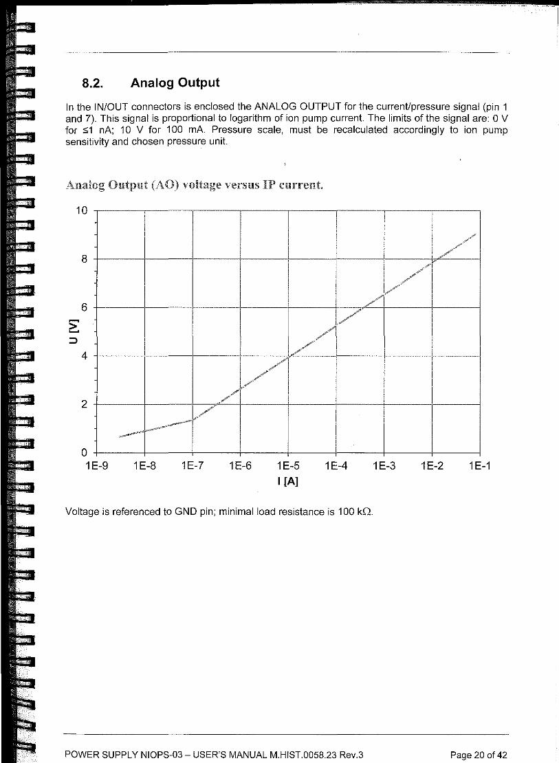
8.2. Analog Output
In the IN/OUT connectors is enclosed the ANALOG OUTPUT for the current/pressure signal (pin 1 and 7). This signal is proportional to logarithm of ion pump current. The limits of the signal are: O V for :51 nA; 10 V for 100 mA. Pressure scale, must be recalculated accordingly to ion pump sensitivity and chosen pressure unit.
Analog Output (AO) voltage versus IP
0 1 E-9 1 E-8 1E-7 1E-6 1 E-5
I [A]
1 E-4
Voltage is referenced to GND pin; minimal load resistance is 100 kQ.
POWER SUPPLY NIOPS-03 - USER'S MANUAL M.HIST.0058.23 Rev.3
1 E-3 1E-2 1 E-1
Page 20 of 42
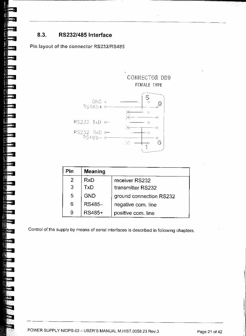
8.3. RS232/485 Interface
Pin layout the connector RS232/RS485
C TOR DB9 FEMALE TYPE
G~IC r~-
RS 5+ o-
RS2.32 TxD o -~ r~-B RS2.J2 RxD o- --- · I 0 -0
liS '.:)-. >E-- ··~o I
I ~ _) \.. ____________ _
Pin Meaning
2 RxD receiver RS232 3 TxD transmitter RS232
5 GND ground connection RS232
6 RS485- negative com. line
9 RS485+ positive com. line
Control of the supply by means of serial interfaces is described in following chapters.
POWER SUPPLY NIOPS-03 - USER'S MANUAL M.HIST.0058.23 Rev.3 Page 21 of 42
9. CONTROL VIA A SERIAL CHANNEL
9.1. Definition
For communication, the RS232 standard serial interface is used in three-wire connection or two wire RS485 serial interface. For RS232 only signals TxD and RxD are used. Both communication channels are galvanically separated from the frame of the supply.
Default communication baud rate for RS485 is '19,200 Bd and for RS232 is 115,200 Bd, 8 data bits, 1 stop-bit, without parity bit, flow control none. To change the values see Sec. 6. With the PC use a Null Modem cable.
In the text below, the following symbols and abbreviations are used:
Symbol Meaning
PC computer PC/AT
NIOPS ion and NEG pump supply NIOPS03
Transmission communication from PC into NIOPS
Reception communication from NIOPS into PC
[ l optional parameter in a command
<CR> carriage return (ASCII 13)
<LF> line feed (ASCII 10)
<ENQ> communication poll (ASCII 5)
<ACK> acknowledgement (ASCII 6)
<NAK> negative acknowledgement (ASCII 21)
9.2. Communication protocol for RS232
All commands are sent in the form of ASCII sequences terminated with <CR>, [<LF>] characters. The character <LF> is optional. After every command transmitted from PC, an acknowledgement has to be waited for (<ACK>, <NAK>). Spaces inside the sequence are ignored.
POWER SUPPLY NIOPS-03 - USER'S MANUAL M.HIST.0058.23 Rev.3 Page 22 of 42
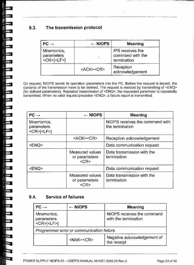
9.3. The transmission protocol
PC---> .-- NIOPS Meaning
Mnemonics, parameters <CR>[<LF>]
<ACK><CR>
IPS receives the command with the termination
Reception acknowledgement
On request, NIOPS sends its operation parameters into the PC. Before the request is issued, the contents of the transmission have to be defined. The request is realized by transmitting of <ENO> (for defined parameters). Repeated transmission of <ENO>, the requested parameter is repeatedly transmitted. When no valid request precedes <ENO>, a failure report is transmitted .
PC___,
Mnemonics, parameters <CR>[<LF>]
<ENQ>
.-- NIOPS
<ACK><CR>
Meaning
NIOPS receives the command with the termination
Reception acknowledgement
Data communication request
Measured values Data transmission with the
<ENQ>
or parameters <CR>
Measured values or parameters
<CR>
9.4. Service of failures
PC--->
Mnemonics, parameters <CR>[<LF>]
.-- NIOPS
termination
Data communication request
Data transmission with the termination
Meaning
NIOPS receives the command with the termination
Programmer error or communication failure
<NAK><CR> Negative acknowledgement of the receipt
POWER SUPPLY NIOPS-03 - USER'S MANUAL M.HIST.0058.23 Rev.3 Page 23 of 42
9.5. The commands used
The software version
Transmission:
Reception: x
y
Example:
The NIOPS status
Transmission:
Reception:
Example:
IP current
Transmission:
Reception:
Transmission:
Reception:
or
Transmission:
Reception:
Example:
or
Transmission:
Reception:
Example:
IP voltage
Transmission:
Reception:
Transmission:
V<CR>[ <LF>]
NIOPSxy<CR> number of version
date of translation
NEGH.3 Jun 04 20ll<CR>
TS<CR>[ <LF>]
report <CR><LF>
IP ON, Switch 2 OFF, Switch 3 OFF, NP ON, Alarm OFF<CR>
I <CR>[ <LF>]
<ACK>
<ENQ>
xxxx<CR>
i <CR>[ <LF>]
xxxx<CR>
4209<CR>
xxxx hexadecimal expression ofa 16-bit number. Two highest bits rr specify the range, the following ones are current i:
rr i
range step
00 0-10 µA 1 nA
01 10 µA-I mA 0,1 µA
10 1 mA-lOOmA 10 µA
(4209H = 0100 0010 0000 lOOIB, rr = 01, i = 100000100h = 521 0 , i = 521 xO,l µA = 52,1 µA)
TI <CR>[ <LF>]
report <CR>
Current 52.1 uA<CR>
U<CR>[ <LF>]
<ACK>
<ENQ>
POWER SUPPLY NIOPS-03 - USER'S MANUAL M.HIST.0058.23 Rev.3 Page 24 of 42
Reception:
or
Transmission:
Reception:
Example:
or
Transmission:
Reception:
Example:
IP pressure
Transmission:
Reception:
Example:
uuuu<CR>
u<CR>[ <LF>]
uuuu<CR>
u u u u is voltage in volts, hexadecimal expression
1388<CR>
(1388H = 50000; 5000 V)
TU<CR>[ <LF>]
report <CR>
Voltage 5.00 kV<CR>
Tx<CR>[ <LF>]
x T expression in Torr B expression in mbar P expression in Pa t expression in Torr (only value) b expression in mbar (only value) p expression in Pa (only value)
report <CR>
Transmission:
Reception:
Transmission:
Reception:
TT<CR>[<LF>]
Pressure 2.6E-07 Torr<CR>
Tt<CR>[<LF>]
2.6E-07<CR>
Switching the lP supply off
Transmission:
Reception:
B<CR>[ <LF>]
$<CR>
Switching the H'supply on
Transmission:
Reception:
G<CR>[ <LF>]
$<CR>
This command switches on the supply, provided it is not prevented owing to overheating, low mains voltage, state of signal IN! or a failure.
Changing the NP type
Transmission: Tx<CR>[<LF>]
x 1 DI00-5
2 D200-5
Reception: <CR>
POWER SUPPLY NIOPS-03 - USER'S MANUAL M.HIST.0058.23 Rev.3 Page 25 of 42
Setting the NEG cable lenght
Transmission:
Reception:
Example:
Lxxx<CR>[<LF>]
xxx actual cable length [ m] x 10
$<CR>
L04 5<CR> [ <LF> J cable length is set to 4.5 m
Swi!chillg the NP supply off
Transmission:
Reception:
BN<CR>[ <LF>]
$<CR>
Switching the NP supply mi
Transmission: GN<CR>[ <LF>]
Reception: $<CR>
This command switches on the supply, provided it is not prevented owing to overheating, low mains voltage, state of signal INl or a failure.
Restart NEG pump parameters (after mains interruption)
Transmission:
Reception:
TE<CR>[<LF>]
NEG Low I: xxxx (Hex)<CR> NEG High I: yyyy (Hex)<CR>
Data are received in format xxxx (yyyy), where xxxx (yyyy) are 16-bit hexadecimal numbers. Two highest bits specify the range; the following ones are the current (see Output IP current on Pag. 24).
The command shows extent of IP current which enables after mains interruption an automatic start of previous NEG pump working parameters.
Example: NEG Low I: 0032 (Hex) <CR>
NEG High I: 2134 (Hex)<CR>
1.e. NEG Low I~ 50 nA NEG High I~ 8.50 uA
Setting NEG pump parameters (after mains interruption)
Transmission:
Reception:
Exxxxyyyy<CR>[<LF>]
xxxx low IP current value in Hex format, see Pag. 24
yyyy high IP current value in Hex format, see Pag. 24
$<CR>
The command sets extent of IP current which enables after mains interruption an automatic start of previous NEG pump working parameters.
Example: E00322134<CR> [<LF>] $<CR>
POWER SUPPLY NIOPS-03 - USER'S MANUAL M.HIST.0058.23 Rev.3 Page 26 of 42
The change of NP mode
Transmission: Mx<CR>[ <LF>] x 1 Activation
2 Timed Activation
3 Conditioning
4 Timed Conditioning Reception: $<CR>
Change of comparator mode
Transmission:
Reception:
Example:
Wx<CR>[<LF>]
x 0 SW2 - simple, SW3 - simple
1 SW2-window, SW3-simple
2 SW2 - simple, SW3 - window
3 SW2 -window, SW3 -window
$<CR>
Wl<CR>[<LF>]
$<CR>
II' cu rrent/pressn re conversion constant
Transmission: TK<CR>[<LF>]
Reception: report <CR>
Example: Pump Constant 65 A/Torr<CR>
Setting IP current/pressure conversion constant
Transmission:
Reception:
Example:
Kxxxx<CR>[<LF>]
xxxx value of conversion constant [A/Torr]( decimal)
$<CR>
K0065<CR>[<LF>]
$<CR>
The TP current comparators setting
Transmission:
Reception:
Pn[ xxxx ]<CR>[ <LF>] n 1 level lH
2 level 2L 3 level 2H 4 level 3L 5 level 3H
xxxx has the same signification as for the current reading $<CR>
If the value xxxx is not transmitted the received answer is topical hexadecimal value of the comparator.
POWER SUPPLY NIOPS-03 - USER'S MANUAL M HIST.0058.23 Rev.3 Page 27 of 42
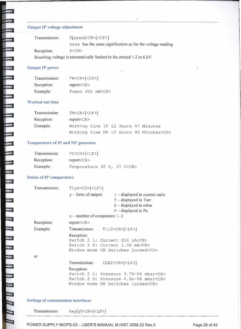
Output IP voltage adjustment
Transmission: U(xxxx]<CR>( <LF>]
xxxx has the same signification as for the voltage reading
Reception: $<CR>
Resulting voltage is automatically limited to the extend 1.2 to 6 kV.
Output IP power
Transmission:
Reception:
Example:
Worked out time
Transmission:
Reception:
Example:
TW<CR>( <LF>]
report<CR>
Power 402 mW<CR>
TM<CR>[ <LF>]
report<CR>
Working time IP 1 2 Hours 47 Minutes
Working time NP 10 Hours 40 Minutes<CR>
Temperature of IP and NP generator
Transmission:
Reception:
Example:
TC<CR>( <LF>]
report<CR>
Tempera ture 32 C, 37 C<CR>
Status of IP comparators
Transmiss ion:
Reception:
Example:
or
TLyz<CR>( <LF>]
y - form of output: I - displayed in current units T - displayed in Torr B - displayed in mbar P - displayed in Pa
z - number of comparator 1-3
report<CR>
Transmission: TLI2<CR>[<LF>]
Reception: Switch 2 L: Current 854 uA<CR> Switch 2 H: Current 1.06 mA<CR> Window mode ON Switches l ocked<CR>
Transmission: TLB2 <CR>[ <LF>]
Reception: Switch 2 L: Pressure 3 . 7E- 06 mbar<CR> Switch 2 H: Pressure 4.SE- 06 mbar<CR> Window mode ON Swi t ches locked<CR>
Settings of commutation interfaces
Transmission: Rxy[y ]<CR>[ <LF>]
POWER SUPPLY NIOPS-03 - USER'S MANUAL M.HIST.0058.23 Rev.3 Page 28 of 42
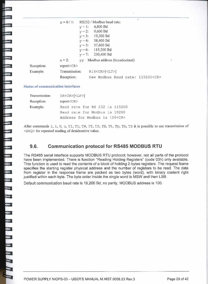
x = 0 I 1: RS232 I Modbus baud rate: y = I: 4,800 Bd y = 2: 9,600 Bd y = 3: 19,200 Bd y = 4: 38,400 Bd y = 5: 57,600 Bd y = 6: 115,200 Bd y = 7: 230,400 Bd
x = 2: yy - Modbus address (hexadecimal)
Reception: report<CR>
Example: Transmission: Rl 6<CR>[ <LF>]
Reception: New Modbus Baud rat e: 115200<CR>
Status of communication interfaces
Transmission:
Reception:
Example:
TR<CR>[ <LF>]
report<CR>
Baud rate f or RS 232 is 1 1 5200
Baud rate for Modbus is 19200
Address for Modbus is lOO<CR>
After commands I, i, U, u, TI, TU, TW, TT, TP, TB, Tt, Tp, Tb, TS it is possible to use transmission of <ENQ> for repeated reading of desiderative value.
9.6. Communication protocol for RS485 MODBUS RTU
The RS485 serial interface supports MODBUS RTU protocol; however, not all parts of the protocol have been implemented. There is function "Reading Holding Registers" (code 03h) only available. This function is used to read the contents of a block of holding 2-bytes registers. The request frame specifies the starting register physical address and the number of registers to be read. The data from register in the response frame are packed as two bytes (word), with binary content right justified within each byte. The byte order inside the single word is MSW and then LSB.
Defau lt communication baud rate is 19,200 Bd, no parity, MODBUS address is 100.
POWER SUPPLY NIOPS-03 - USER'S MANUAL M.HIST.0058.23 Rev.3 Page 29 of 42
I
I I
I '
I
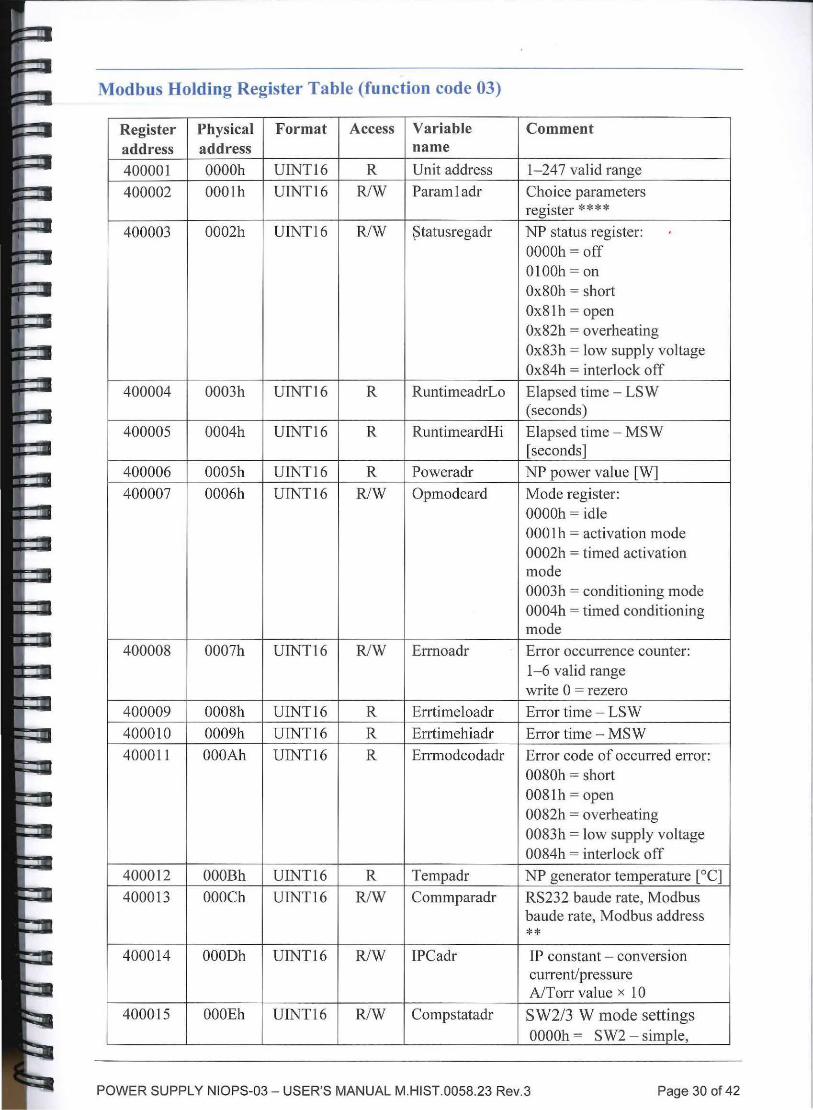
Modbus Holding Register Table (function code 03)
Register Physical Format Access Variable Comment address address name
400001 OOOOh UINT16 R Unit address 1-247 valid range
400002 OOOlh UINT16 RJW Paramladr Choice parameters register * * * *
400003 0002h UINT16 R/W ~ tatusregadr NP status register: OOOOh = off OlOOh = on Ox80h = short Ox8lh = open Ox82h = overheating Ox83h = low supply voltage Ox84h = interlock off
400004 0003h UINT16 R RuntimeadrLo Elapsed time - LS W (seconds)
400005 0004h UINT16 R RuntimeardHi Elapsed time - MSW [seconds]
400006 0005h UINT16 R Poweradr NP power value [W]
400007 0006h UINT16 R/W Opmodeard Mode register: OOOOh = idle 000 l h = activation mode 0002h = timed activation mode 0003h = conditioning mode 0004h = timed conditioning mode
400008 0007h UINT16 R/W Ermoadr Error occurrence counter: 1-6 valid range write 0 = rezero
400009 0008h UINT16 R Errtimeloadr Error time - LSW
400010 0009h UINT16 R Errtimehiadr Error time - MSW
400011 OOOAh UINT16 R Errmodcodadr Error code of occurred error: 0080h = short 0081 h =open 0082h = overheating 0083h = low supply voltage 0084h = interlock off
400012 OOOBh UINT16 R Tempadr NP generator temperature [0 C] 400013 OOOCh UINT16 R/W Commparadr RS232 baude rate, Modbus
baude rate, Modbus address **
400014 OOODh UINT16 R/W IPCadr IP constant - conversion current/pressure A/Torr value x 10
400015 OOOEh UINT16 R/W Compstatadr S W2/3 W mode settings OOOOh = SW2 - sim_Q_le,
POWER SUPPLY NIOPS-03 - USER'S MANUAL M.HIST.0058.23 Rev.3 Page 30 of 42
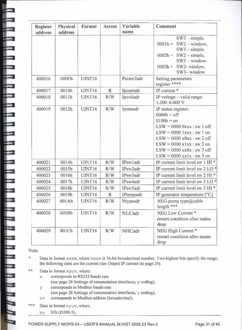
Register Physical Format Access Variable Comment address address name
SW3 - simple. OOOlh = S W2 - window,
S W3 - simple. 0002h= SW2 - simple,
SW3 - window. 0003h = SW2- wind9w,
' SW3-window
400016 OOOFh UINT16 Param2adr Setting parameters register****
400017 0010h UTNT16 R lpcurradr IP current*
400018 001 lh UINT16 R/W Tpvoltadr IP voltage - valid range: 1.200-6.000 v
400019 0012h UINT16 R/W Ipstatadr IP status register: OOOOh =off OIOOh =on LSW = 0000 Oxxx : sw 1 off LSW = 0000 lxxx: sw 1 on LS W = 0000 xOxx : sw 2 off LSW = 0000 xlxx: sw 2 on LSW = 0000 xxOx: sw 3 off LSW = 0000 xxlx: sw 3 on
40002 1 0014h UINT16 R/W IPswladr IP current limit level sw 1 HI * 400022 0015h UINT16 R/W 1Psw2adr IP current limit level sw 2 LO*
400023 0016h UINT16 RJW IPsw3adr IP current limit level sw 2 HI *
400024 001 7h UINT16 R/W 1Psw4adr IP current limit level sw 3 LO *
400025 0018h UINT16 R/W 1Psw5adr IP current limit level sw 3 HI*
400026 0019h UINT16 R lPtempadr IP generator temperature [°C]
400027 OOlAh UINT16 RJW Ntypeadr NEG pump type@cable length ***
400028 001Bh UINT16 RJW NLCadr NEG Low Current * restart condition after mains drop
400029 OOlCh UTNT16 R/W NHCadr NEG High Current * restart condition after mains drop
Note:
*
**
***
Data in format xxxx, where xxxx is 16-bit hexadecimal number. Two highest bits specify the range; the following ones are the current (see Output IP current on page 24).
Data in format xyuv, where: x corresponds to RS232 baude rate
(see page 28 Settings of commutation interfaces, y coding), y corresponds to Modbus baude rate
(see page 28 Settings of commutation interfaces, y coding), u v corresponds to Modbus address (hexadecimal).
Data in format xyuv, where:
xy Olh (Dl00-5),
POWER SUPPLY NIOPS-03 - USER'S MANUAL M.HIST.0058.23 Rev.3 Page 31 of 42
I I
I I
02h (0200-5), uv (cable length [m] x I 0) h.
****Value at address 2- content selector of address 16: O OAC value of CON of the pump 0100, 1 OAC value of CON of the pump 0200, 2 OAC value of ACT of the pump 0100, 3 OAC value of ACT of the pump 0200; Value at address 16 - basic value of OAC for chosen mode and pump. To preserve this setting use following sequence; - write value of 255 at address 2, - write any value at address 16.
Note: The values of OAC shown in service mode differ from those ones set (see previous paragraph). The service mode values comprise compensation for cable length.
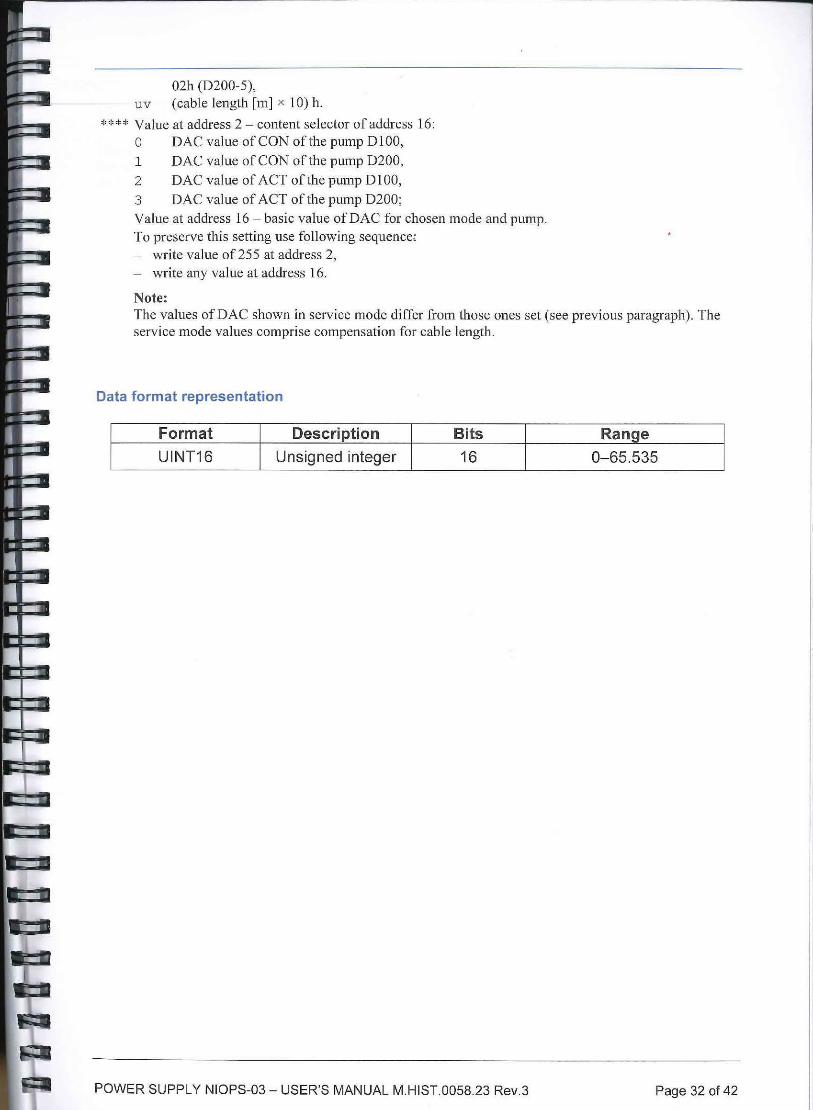
Data format representation
Format Description Bits Range UINT16 Unsigned integer 16 0-65.535
POWER SUPPLY NIOPS-03 - USER'S MANUAL M.HIST.0058.23 Rev.3 Page 32 of 42
10. MAINTENANCE AND TROUBLESHOOTING
The supply needs minimum maintenance. Depending on the dust levels in the environment where the device is being operated, a periodic check of the vents on upper and lower side of the device and outlet of the fan is desirable. In case of dust contamination it can be cleaned by means of a vacuum cleaner.
The only repair left to the user is the replacement of the mains fuse on the rear panel in the mains plug body. It is easy to recognize when a fuse has burnt out because after the mains switch LINE is pushed to the position I, neither it nor the display lights. If the fuse burns out even after having been substituted several times, some more serious failure is involved and the supply should be shipped for repair.
List of warnings:
• Wait - The initialization process is active after the mains switch was switched on.
• Disabled- The supply is disabled by wrong connection of interlock input IN see Sec. 3 and 8.
• Act is running - NP is running. The action requires the switching off of the NEG pump
• Switch OFF IP- IP is running. The action requires the switching off of the ION pump.
10.1. NP troubleshooting
Whenever during a running mode a failure in NEG pump or supply unit appears the running mode is interrupted (output voltage is set to zero) and type of failure is shown on display:
• Open! - interrupted heating circuit of NEG pump or disconnected cable;
• Short! - short circuit of heating element of NEG pump to frame or shorted leads of heating element;
• High Temp - the temperature inside unit has overcome 65 °C;
• Low Voltage - low mains voltage for chosen working mode;
At the same time the yellow indicator starts to blink, a number of failure counts is lighted on and alarm sound is generated . The indicator blinking and sound will last until the reason of failure report is removed. As soon as the NP supply unit is repaired, the previous operational mode is displayed and the supply unit can be started again.
When the supply is in STOP state it is possible to show details of any failure from recorded list (up to 6) by simultaneous pressing of pushbuttons A/VIW, Torr/Pa/mbar and with slight delay MODE in NEG section. The latest failure is shown as the first and pressing pushbutton MODE repeatedly it goes successively to the first one and leaves the list at last. Displayed failure is marked by number at the end of display line. The display shows an abbreviation of working mode, type of failure and time when the failure occurred. When the number of failures is more than 6, the list is shifted so that the latest event would be recorded and the oldest one is lost. To clean the failure list, in list display, it is necessary to press the pushbutton ON/OFF in NEG section longer time until the count of failures disappears.
List of failure abbreviations shown on display:
• Opn - stands for Open,
• Sht - stands for Short,
POWER SUPPLY NIOPS-03 - USER'S MANUAL M.HIST.0058.23 Rev.3 Page 33 of 42
• LoV - stands for Low Voltage,
• HiT- stands for High Temp.
List of setting errors shown on display:
• Overload! Check setting - the power to NEG pump exceeded the allowed limit. Check correct setting of NEG pump type, length of used cable and final value of AD (see SERVICE MODE NP). If the previously mentioned items are correct then the resistance of heating element might be too small.
• Check setting - the power to NEG pump is smaller than necessary limit. Check correct setting of NEG pump type, length of used cable and final value of AD (see SERVICE MODE NP).
10.2. IP troubleshooting
During a runn ing mode of the ION pump may be displayed these messages:
• Arcing - The message with accompanying sound signal will appear after automatic switching off of the power supply due to either an unstable electric arc in ion element or an arc of high voltage in the circuit of ion element cable. In this situation, the power supply will try to switch on and if the third attempt is not successful, the supply remains permanently switched off with error report and sound signal. The remedy is to forepump to higher vacuum or to remove the reason of arcing. It is possible to switch on the supply unit again by pushing the ON/OFF pushbutton.
• Overload - The supply stayed switched off after previous unsuccessful attempts at an automatic start. The pump current apparently went over the value of the comparator 1 H. The switching off is signaled by an acoustic sound as well. Start of the supply can be made by pressing the ON/OFF pushbutton.
• Switch locked - This report can appear after pressing the pushbutton or when trying to change some of any adjustable values. If a new adjustment is needed it is necessary to unlock the switches first (see Sec. 6).
• High Temp - The supply is switched off as a consequence of overheating the generator HV. This circumstance can occur at high ambi-ent temperature and simultaneously maximal output power of the supply. The switching off is signaled by an acoustic sound as well. After decrease of inner temperature the supply will start automatically again. If the failure lasts too long time or it appears too often the reason for it might be:
Excessive high ambient temperature. Reduce the ambient temperature or load of the supply.
- A failure of the supply fan. Ensure a repair. (The fan runs if the temperature in-creases over 45 °C and stops if the temperature decreases bellow 40 °C - see Sec. 6). An insufficient flow of cooling air through vents. Ensure a sufficient air flow, leave the supply switch on. After being cooled by its fan the supply will start.
• Low Voltage - The supply is switched off as a consequence of low mains voltage (under low margin of working extent) apparently at high output power. The switching off is signaled by an acoustic sound as well. As long as this state remains it is probable that the failure message and operating regime will change periodically until sufficient mains voltage is ensured.
• Starting - It indicates an attempt to start HV generator, which does not work for other reasons than overcurrent stop.
• Error - It indicates switching off the generator HV when the load current, of 90 mA, was exceeded repeatedly (possible short circuit in the HV cable, in the pump or bad forevacuum). The switching off is signaled by an acoustic sound as well. Disconnecting the HV cable from the
POWER SUPPLY NIOPS-03 - USER'S MANUAL M.HIST.0058.23 Rev.3 Page 34 of 42
supply, and switch on the IP, if the failure message continues there is a supply failure and the device must be shipped for repair (see Sec. 15).
• Internal Error - It indicates an error in internal communication of the unit. If the failure message continues after the switch off/on of the instrument there is a supply failure and the device must be shipped for repair (see Sec. 15).
• * (asterisk) - The asterisk shows up when the IP current reaches 0 nA. This means the pressure inside the IP is so low that the curre,nt is below detection limit.
&. warning
In the case the HV cable is disconnected, the current will be O and the asterisk will show up as well.
POWER SUPPLY NIOPS-03 - USER'S MANUAL M.HIST.0058.23 Rev.3 Page 35 of 42
11. SPECIFICATIONS
IP Section
Nominal output voltage Range of adjustment Output voltage polarity Output voltage ripple (informatively)
Maximum output current Obtainable output power
at lou1 = 0.5 mA at lou; = 5 mA
5 kV±2 % 1.2+6 kV
positive
approx. 1 V P--P I 20 .kHz approx. 10 V P--P I 20 kHz
89.9 mA 25-30 w
NP Section NEXTorr 0100-5
Nominal output voltage Activation and Timed Activation mode 9V±2%
4.5V Conditioning and Timed Conditioning mode
(voltage for both modes is adjustable)
Output power for Activation and Timed Activation mode 45 W
NP Section NEXTorr 0200-5
Nominal output voltage Activation and Timed Activation mode
Conditioning and Timed Conditioning mode
(voltage for both modes is adjustable)
12.5 V±2 %
6.2 v
Output power for Activation and Timed Activation mode 60 W
Complete unit
Outputs 5x current comparators-switches* positive feeding voltage negative terminal
* max. voltage between switched off terminals max. current through connected terminals
Inputs
enable input
Communication interface
Mains voltage
Maximal consumption
Fusing
Weight
Ambient temperature at operation
Relative humidity
RS232
RS485
on: Z = 13±2 O +5 VI 20 mA
GND
30 v 100mA
2-10mA/2kO
4,800-230,400 Bd
4,800-230,400 Bd
90+260 VI 48+63 Hz
230VA
T2A
3.2 kg
5+40 °C
20+80 %
The device is an instrument of safety class I and fully complies with the requirements for electrical equipments of the Directive 2006/95/EC for measure, control and laboratory use.
POWER SUPPLY NIOPS-03 - USER'S MANUAL M.HIST.0058.23 Rev.3 Page 36 of 42
12. INSTRUCTION FOR INSTRUMENT DISPOSAL
The instrument disposal should be carried out in compliance with the user's country applicable regulations.
The instrument contains materials which may endanger the environment. When disposing of the instrument, separate disassembly by material is to be arranged for and the different materials shall be collected separately for disposal. Neither the collection nor the transport of thus coJlected and separated materials is subject to any special requirements.
POWER SUPPLY NIOPS-03 - USER'S MANUAL M.HIST.0058.23 Rev.3 Page 37 of 42
13. PRODUCT CONFIGURATIONS AND ACCESSORIES
Configurations and accessories are given in the following section:
Product description Code Note
- NEXTorr Power Supply NIOPS-03 3B0408 Power supply for NEXTorr Getter Pumps I
- NIOPS-03 KIT OF CABLES-03 (3 pcs) 3B0409 ION, NEG pumps and main cables (standard)
- NIOPS-03 OUTPUT CABLE ION 3mt 380410 ION Pump cable 3 m length (standard)
- NIOPS-03 OUTPUT CABLE NEG 3mt 3B0411 NEG Pump cable 3 m length (standard)
- NIOPS INPUT CABLE 3B0398 European plug Schuko P660
- RS485/232 CONVERTER 3B0379 To operate the power supply via RS485/232
POWER SUPPLY NIOPS-03 - USER'S MANUAL M.HIST.0058.23 Rev.3 Page 38 of 42
14. WARRANTY CONDITIONS
SAES guarantees that the Products delivered shall be free from operational and material defects and shall comply with the construction and functional data and specifications indicated in the Contractual Documents. This warranty shall have a term of TWELVE (12) MONTHS. For Products which require installation at BUYER's facility by SAES pe~sonnel , the warranty shall have a- term of TWELVE (12) MONTHS from the date of installation or FOURTEEN (14) MONTHS from the date of delivery, whichever term is shorter. Subject to the remainder of this Article 14, any action by BUYER for any alleged breach of this warranty shall be brought in writing by BUYER within thirty (30) days of BUYER's discovery of the breach. This warranty shall only apply to the BUYER and may not be assigned. During the term of the warranty set forth above, SAES will promptly repair the Products which for their features can be repaired and which do not conform to the specifications and which BUYER returns to SAES at the address provided. Unless otherwise agreed and specified, BUYER shall be responsible for all transportation charges incurred in returning Products to SAES for repair; BUYER shall have obtained a Returned Material Authorization ("RMA") number and specific shipping instructions from SAES prior to its shipping of the Products to SAES. SAES shall not unreasonably deny BUYER authorization to ship Products to SAES. SAES shall return repaired Products to BUYER, with transportation charges prepaid by SAES, unless otherwise agreed. Additional information is available on the General conditions of sales .
POWER SUPPLY NIOPS-03 - USER'S MANUAL M.HIST.0058.23 Rev.3 Paoe 39 of 42
15. SERVICE
In case of a failure, please check if the fuse located on the supply rear panel has not blown. If the failure persists after the fuse has been replaced , inform the manufacturer who will repair the supply.
For a request of return of the instrument please contact SAES Customer Service:
15.1. Sales & Service Locations:
Europe, Middle East and Africa:
SAES Getters S.p.A. Viale Italia 77 20020 Lainate {Milan) - Italy Ph. +39 02 93178 1 - Fax +39 02 93178 320
European Customer Relations: Ph. +39 02 9317 8402 - Fax +39 02 93178320 E-mail: [email protected]
Asia and Oceania:
SAES Getters S.p.A. - Japan Technical Service
Branch Office 2nd Gotanda Fujikoshi Bldg. 23-1 Higashi Gotanda 5-Chome Tokyo 141, Japan Ph. +81 3 542 00431 - Fax +81 3 542 00438
SAES Getters (Nanjing) Co.,Ltd. 56 Xingangdadao, Xinshengwei Nanjing Economic & Technical Development Zone Nanj ing 210038, Jangsu Province, P.R. of China Ph. +86 25 8580 2335 - Fax +86 25 8580 1639
SAES Getters Korea Corporation 7th Fl. Dongwon Bldg. 143-28 Samsung-dong, Gangnam-gu Seoul 135-877, Korea Ph. +82 2 3404 2400 - Fax +82 2 3452 4510/1 1
SAES Getters S.p.A. - Taiwan Branch Office 6F-1, No. 1071, Zhongzheng Road, Taoyuan City, Taoyuan County 330 Taiwan, R.O.C. Fax +886 3 346 8290
North and South America:
SAES Getters USA, Inc. 1122 East Cheyenne Mountain Blvd. Colorado Springs, CO 80906 - USA Ph. +1 719 576 3200 - Fax + 1 719 576 5025
POWER SUPPLY NIOPS-03 - USER'S MANUAL M.HIST.0058.23 Rev.3 Page 40 of 42
Remember that SAES cannot accept any instrument which contains biological or chemical hazards or radioactive substances. Please clearly inform SAES Customer Service should this have happened during pump use, so to discuss adequate solutions.
POWER SUPPLY NIOPS-03 - USER'S MANUAL M.HIST.0058.23 Rev.3 Page 41 of 42