Embed Size (px)
Citation preview
Spartan 6 Decoder Tutorial EE574/ECE3810
Copyright © 2011 R James Duckworth 1 Rev A
Nexys 3 board tutorial (Decoder, ISE 13.2)
Jim Duckworth, August 2011, WPI.
Note: you will need the Xilinx ISE Webpack installed on your computer (or you can use the
department systems).
[Note you can also review Xilinx Tutorials, for example, under Design Resources: ISE Design
Suite Tutorials, and ISE Design Suite Logic Edition - Quick Tour]
Start Xilinx ISE Design Suite,
Select File => New Project or click on New Project
and enter "decoder" for the project name (select an appropriate location):
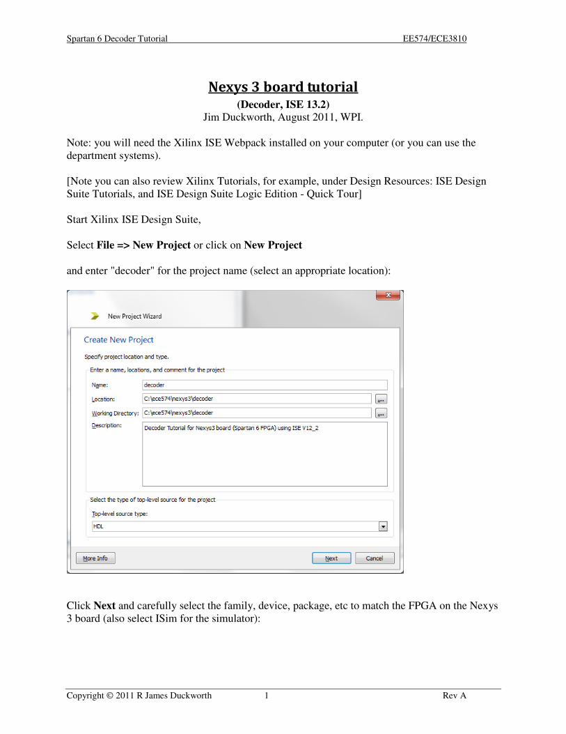
Click Next and carefully select the family, device, package, etc to match the FPGA on the Nexys
3 board (also select ISim for the simulator):
Spartan 6 Decoder Tutorial EE574/ECE3810
Copyright © 2011 R James Duckworth 2 Rev A
Click Next, and then click Finish
Spartan 6 Decoder Tutorial EE574/ECE3810
Copyright © 2011 R James Duckworth 3 Rev A
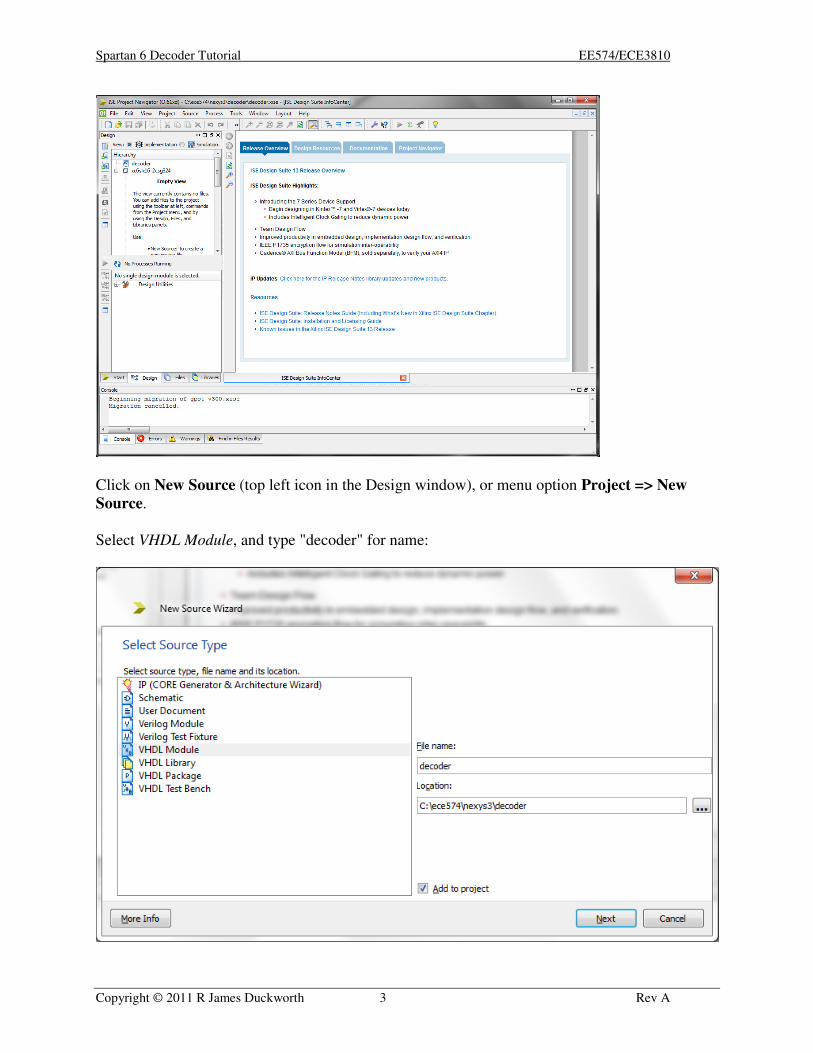
Click on New Source (top left icon in the Design window), or menu option Project => New
Source.
Select VHDL Module, and type "decoder" for name:
Spartan 6 Decoder Tutorial EE574/ECE3810
Copyright © 2011 R James Duckworth 4 Rev A
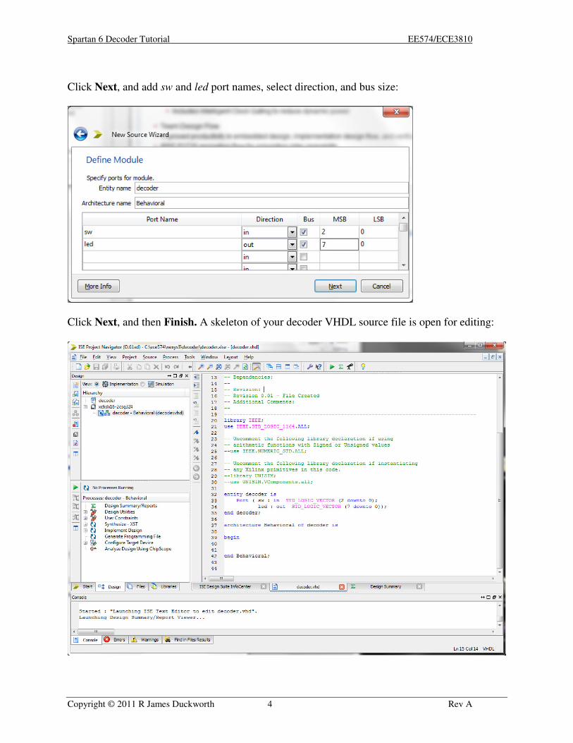
Click Next, and add sw and led port names, select direction, and bus size:
Click Next, and then Finish. A skeleton of your decoder VHDL source file is open for editing:
Spartan 6 Decoder Tutorial EE574/ECE3810
Copyright © 2011 R James Duckworth 5 Rev A
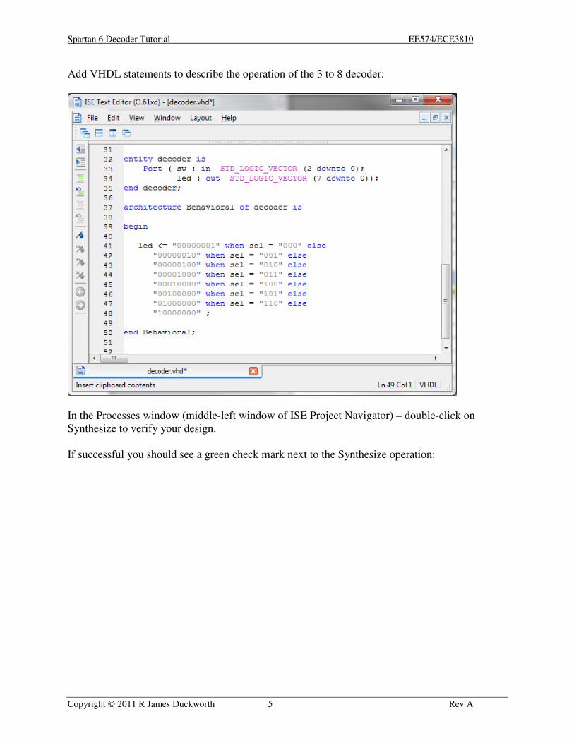
Add VHDL statements to describe the operation of the 3 to 8 decoder:
In the Processes window (middle-left window of ISE Project Navigator) – double-click on
Synthesize to verify your design.
If successful you should see a green check mark next to the Synthesize operation:
Spartan 6 Decoder Tutorial EE574/ECE3810
Copyright © 2011 R James Duckworth 6 Rev A
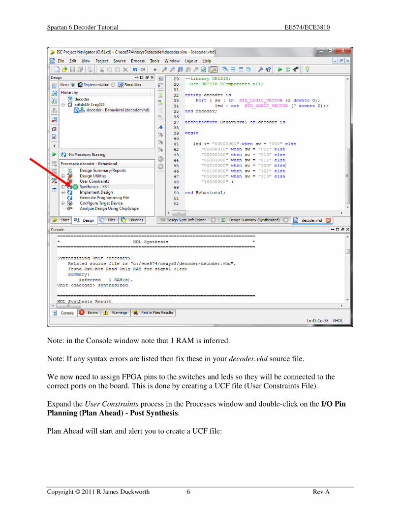
Note: in the Console window note that 1 RAM is inferred.
Note: If any syntax errors are listed then fix these in your decoder.vhd source file.
We now need to assign FPGA pins to the switches and leds so they will be connected to the
correct ports on the board. This is done by creating a UCF file (User Constraints File).
Expand the User Constraints process in the Processes window and double-click on the I/O Pin
Planning (Plan Ahead) - Post Synthesis.
Plan Ahead will start and alert you to create a UCF file:
Spartan 6 Decoder Tutorial EE574/ECE3810
Copyright © 2011 R James Duckworth 7 Rev A
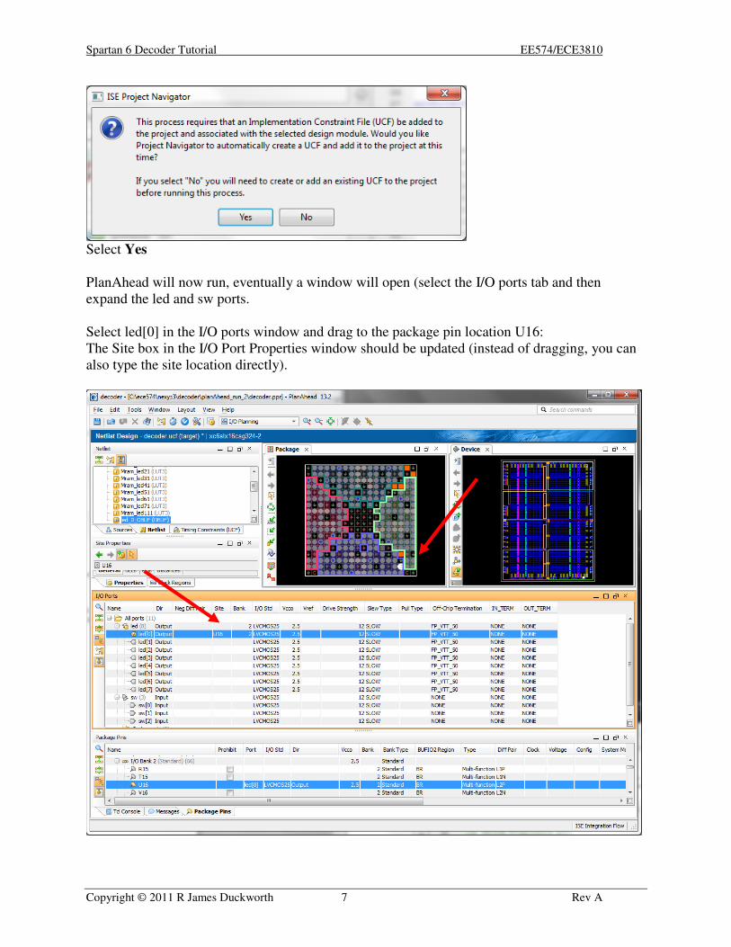
Select Yes
PlanAhead will now run, eventually a window will open (select the I/O ports tab and then
expand the led and sw ports.
Select led[0] in the I/O ports window and drag to the package pin location U16:
The Site box in the I/O Port Properties window should be updated (instead of dragging, you can
also type the site location directly).
Spartan 6 Decoder Tutorial EE574/ECE3810
Copyright © 2011 R James Duckworth 8 Rev A
With reference to the Nexys3 Reference Manual complete the pin information for the rest of the
led and sw ports.
Select File => Save Design and exit PlanAhead.
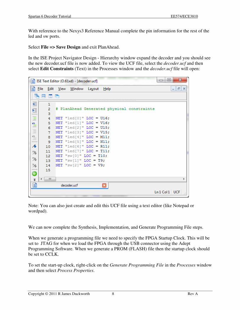
In the ISE Project Navigator Design - Hierarchy window expand the decoder and you should see
the new decoder.ucf file is now added. To view the UCF file, select the decoder.ucf and then
select Edit Constraints (Text) in the Processes window and the decoder.ucf file will open:
Note: You can also just create and edit this UCF file using a text editor (like Notepad or
wordpad).
We can now complete the Synthesis, Implementation, and Generate Programming File steps.
When we generate a programming file we need to specify the FPGA Startup Clock. This will be
set to JTAG for when we load the FPGA through the USB connector using the Adept
Programming Software. When we generate a PROM (FLASH) file then the startup clock should
be set to CCLK.
To set the start-up clock, right-click on the Generate Programming File in the Processes window
and then select Process Properties.
Spartan 6 Decoder Tutorial EE574/ECE3810
Copyright © 2011 R James Duckworth 9 Rev A
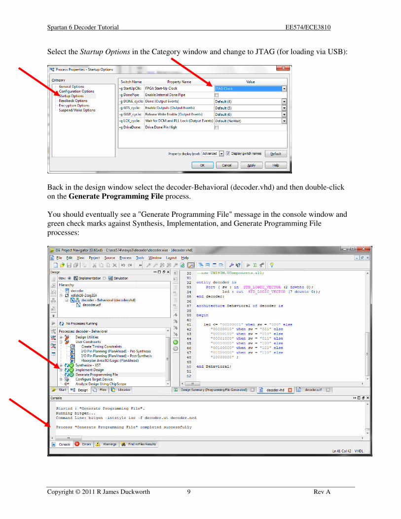
Select the Startup Options in the Category window and change to JTAG (for loading via USB):
Back in the design window select the decoder-Behavioral (decoder.vhd) and then double-click
on the Generate Programming File process.
You should eventually see a "Generate Programming File" message in the console window and
green check marks against Synthesis, Implementation, and Generate Programming File
processes:
Spartan 6 Decoder Tutorial EE574/ECE3810
Copyright © 2011 R James Duckworth 10 Rev A
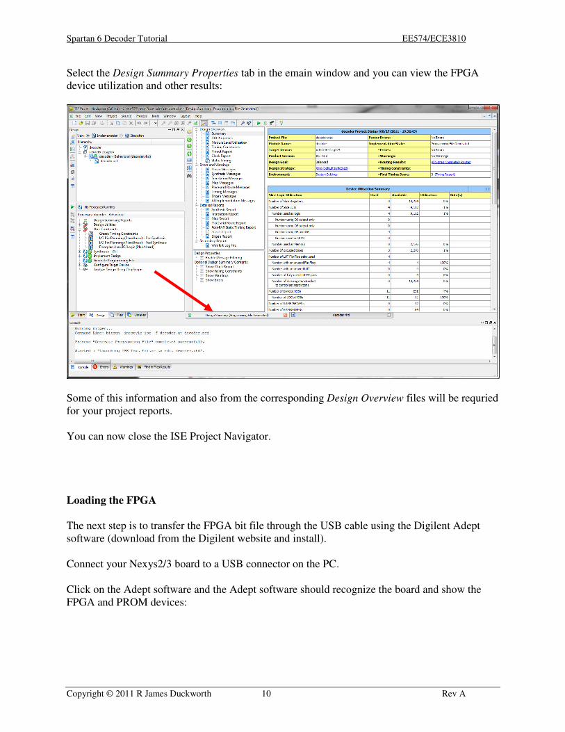
Select the Design Summary Properties tab in the emain window and you can view the FPGA
device utilization and other results:
Some of this information and also from the corresponding Design Overview files will be requried
for your project reports.
You can now close the ISE Project Navigator.
Loading the FPGA
The next step is to transfer the FPGA bit file through the USB cable using the Digilent Adept
software (download from the Digilent website and install).
Connect your Nexys2/3 board to a USB connector on the PC.
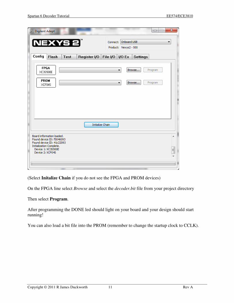
Click on the Adept software and the Adept software should recognize the board and show the
FPGA and PROM devices:
Spartan 6 Decoder Tutorial EE574/ECE3810
Copyright © 2011 R James Duckworth 11 Rev A
(Select Initalize Chain if you do not see the FPGA and PROM devices)
On the FPGA line select Browse and select the decoder.bit file from your project directory
Then select Program.
After programming the DONE led should light on your board and your design should start
running!
You can also load a bit file into the PROM (remember to change the startup clock to CCLK).