Embed Size (px)
Citation preview
First Revision No. 33-NFPA 59-2015 [ Detail ]
Add new section and new annex material:
13.2.4*
Where utilized, leak detection shall not be used in lieu of gas detection but may be used in additionto gas detection.
A.13.2.4
Leak detection used to compliment gas detection systems, leak detection may include acoustic(ultrasonic), which detects small leak rates (mass/time), vapor cloud video surveillance cameras,which detects gas cloud size, low temperature detectors, including resistance temperaturedetectors (RTD), and linear leak detection (such as fiber optic leak detection technology).
Submitter Information Verification
Submitter Full Name: Eric Nette
Organization: National Fire Protection Assoc
Street Address:
City:
State:
Zip:
Submittal Date: Mon Dec 21 13:39:42 EST 2015
Committee Statement
CommitteeStatement:
The recognition of leak detection in 13.2 to compliment gas detection at facilities handlingrefrigerated LPG is appropriate and aligns with similar actions taken by the NFPA 59A TC at thelast second draft meeting. The annex text provides users examples of leak detection and systemsthat might be used to enhance gas detection.
ResponseMessage:
National Fire Protection Association Report http://submittals.nfpa.org/TerraViewWeb/ContentFetcher?commentPara...
1 of 56 1/26/2016 7:34 AM
NFPA 59 First Revision Report - Page 1 of 57 - 1/26/2016
First Revision No. 1-NFPA 59-2015 [ Section No. 2.3 ]
National Fire Protection Association Report http://submittals.nfpa.org/TerraViewWeb/ContentFetcher?commentPara...
2 of 56 1/26/2016 7:34 AM
NFPA 59 First Revision Report - Page 2 of 57 - 1/26/2016
2.3 Other Publications.
2.3.1 ACI Publications.
American Concrete Institute, 38800 Country Club Drive, Farmington Hills, MI 48331-3439.
ACI 376, Code Requirements for Design and Construction of Concrete Structures for the Containmentof Refrigerated Liquefied Gases , 2013.
2.3.2 API Publications.
American Petroleum Institute, 1220 L Street, NW, Washington, DC 20005-4070.
API 6FA, Specifications for Fire Tests for Valves, 2008, reaffirmed 2011 .
API 607/ISO 10497 , Fire Test for Soft-Seated Quarter-Turn Valves Fire Test for Quarter-Turn Valves andValves Equipped with Nonmetallic Seats , 2005.
API 620, Design and Construction of Large, Welded, Low-Pressure Storage Tanks,2008 with 2009addendum 1, 2010 addendum 2, and 2012 addendum 3 2013 with Addendum 1, 2014 .
API 625, Tank Systems for Refrigerated Liquefied Gas Storage , 2010.
2.3.3 ASCE Publications.
American Society of Civil Engineers, 1801 Alexander Bell Drive, Reston, VA 20191-4400.
ASCE 7–05 ASCE/SEI 7–10 , Minimum Design Loads for Buildings and Other Structures,2005 withSupplement #1 2013 .
2.3.4 ASME Publications.
American Society of Mechanical Engineers, Three Two Park Avenue, New York, NY 10016-5990.
ASME Boiler and Pressure Vessel Code, 1949 and 2010 editions with July 2011 supplements.
ASME B31.3, Process Piping, 2010 2014 .
Boiler and Pressure Vessel Code , 2015.
2.3.5 ASTM Publications.
ASTM International, 100 Barr Harbor Drive, P.O. Box C700, West Conshohocken, PA 19428-2959.
ASTM A47/A47M , Standard Specification for Ferritic Malleable Iron Castings,2009 2014 .
ASTM A395/A395M , Specification for Ferritic Ductile Iron Pressure-Retaining Castings for Use atElevated Temperatures, 2009 2014 .
ASTM A536, Specifications for Ductile Iron Castings, 2009 2014 .
2.3.6 UL Publications.
Underwriters Laboratories Inc., 333 Pfingsten Road, Northbrook, IL 60062-2096.
ANSI/ UL 132, Standard on Safety Relief Valves for Anhydrous Ammonia and LP-Gas, 2007 2015 , with2010 amendment .
2.3.7 U.S. Government Publications.
U.S. Government Printing Publishing Office, 732 North Capitol Street, NW, Washington, DC20402 20401-0001 .
Title 49, Code of Federal Regulations, Part 192, “Pipeline Safety Law Transportation of Natural and OtherGas by Pipeline: Minimum Federal Safety Standards .”
Title 49, Code of Federal Regulations, Part 195, "Transportation of Hazardous Liquids by Pipeline."
2.3.8 Other Publications.
Merriam-Webster’s Collegiate Dictionary, 11th edition, Merriam-Webster, Inc., Springfield, MA, 2003.
Submitter Information Verification
Submitter Full Name: Eric Nette
National Fire Protection Association Report http://submittals.nfpa.org/TerraViewWeb/ContentFetcher?commentPara...
3 of 56 1/26/2016 7:34 AM
NFPA 59 First Revision Report - Page 3 of 57 - 1/26/2016
Organization: [ Not Specified ]
Street Address:
City:
State:
Zip:
Submittal Date: Wed Oct 28 10:34:36 EDT 2015
Committee Statement
CommitteeStatement:
Referenced current SDO names, addresses, standards names, numbers, and editions.Instructions to staff to update before ballot. Staff is also instructed to incorporate new referencesfrom PI-10 and PI-11 for revised Chapter 6. Staff is directed to leave the ANSI designations on thecurrent documents as appropriate.
ResponseMessage:
Public Input No. 2-NFPA 59-2015 [Section No. 2.3]
National Fire Protection Association Report http://submittals.nfpa.org/TerraViewWeb/ContentFetcher?commentPara...
4 of 56 1/26/2016 7:34 AM
NFPA 59 First Revision Report - Page 4 of 57 - 1/26/2016

First Revision No. 35-NFPA 59-2015 [ Section No. 2.4 ]
2.4 References for Extracts in Mandatory Sections.
NFPA 54, National Fuel Gas Code, 2015 edition.
NFPA 58, Liquefied Petroleum Gas Code, 2014 2017 edition.
NFPA 5000®, Building Construction and Safety Code®, 2015 edition.
Submitter Information Verification
Submitter Full Name: Eric Nette
Organization: National Fire Protection Assoc
Street Address:
City:
State:
Zip:
Submittal Date: Wed Dec 30 10:02:42 EST 2015
Committee Statement
Committee Statement: Edition year for NFPA 58 was updated.
Response Message:
National Fire Protection Association Report http://submittals.nfpa.org/TerraViewWeb/ContentFetcher?commentPara...
5 of 56 1/26/2016 7:34 AM
NFPA 59 First Revision Report - Page 5 of 57 - 1/26/2016

First Revision No. 37-NFPA 59-2016 [ Section No. 3.3.5 ]
3.3.5 ASTM.
American Society for Testing and Materials. [ 58, 2014]
Submitter Information Verification
Submitter Full Name: Eric Nette
Organization: National Fire Protection Assoc
Street Address:
City:
State:
Zip:
Submittal Date: Mon Jan 04 13:28:03 EST 2016
Committee Statement
Committee Statement: This definition was removed from the 2017 edition of NFPA 58.
Response Message:
National Fire Protection Association Report http://submittals.nfpa.org/TerraViewWeb/ContentFetcher?commentPara...
6 of 56 1/26/2016 7:34 AM
NFPA 59 First Revision Report - Page 6 of 57 - 1/26/2016
First Revision No. 30-NFPA 59-2015 [ Section No. 4.5.2.3 ]
4.5.2.3
The provisions of 4.5.2.2 shall apply to vehicular fuel operations. [ 58: 6.23.2.3]
Submitter Information Verification
Submitter Full Name: Eric Nette
Organization: [ Not Specified ]
Street Address:
City:
State:
Zip:
Submittal Date: Fri Oct 30 10:32:48 CDT 2015
Committee Statement
Committee Statement: Vehicular fuel operations are not within the scope of this document.
Response Message:
National Fire Protection Association Report http://submittals.nfpa.org/TerraViewWeb/ContentFetcher?commentPara...
7 of 56 1/26/2016 7:34 AM
NFPA 59 First Revision Report - Page 7 of 57 - 1/26/2016
First Revision No. 28-NFPA 59-2015 [ Section No. 4.7 ]
4.7 Fixed Electrical Equipment in Classified Areas.
4.7.1
Direct-fired vaporizers, calorimeters with open flames, and other areas where open flames are present,either intermittently or constantly, shall not be considered electrically classified areas.
Submitter Information Verification
Submitter Full Name: Eric Nette
Organization: [ Not Specified ]
Street Address:
City:
State:
Zip:
Submittal Date: Fri Oct 30 10:15:39 CDT 2015
Committee Statement
Committee Statement: This requirement is repetitive and already covered by 4.5.2.4.
Response Message:
National Fire Protection Association Report http://submittals.nfpa.org/TerraViewWeb/ContentFetcher?commentPara...
8 of 56 1/26/2016 7:34 AM
NFPA 59 First Revision Report - Page 8 of 57 - 1/26/2016
First Revision No. 38-NFPA 59-2016 [ Section No. 5.5.3 ]
5.5.3
Field welding on containers shall be limited to attachments to nonpressure parts such as saddle plates,wear plates, or brackets applied installed by the container manufacturer. [58:6.24.3.4(D) 6.8.1.3 ]
Submitter Information Verification
Submitter Full Name: Eric Nette
Organization: National Fire Protection Assoc
Street Address:
City:
State:
Zip:
Submittal Date: Tue Jan 05 11:05:33 EST 2016
Committee Statement
Committee Statement: Text has been updated to match the extracted text from NFPA 58 2017 edition.
Response Message:
National Fire Protection Association Report http://submittals.nfpa.org/TerraViewWeb/ContentFetcher?commentPara...
9 of 56 1/26/2016 7:34 AM
NFPA 59 First Revision Report - Page 9 of 57 - 1/26/2016
First Revision No. 3-NFPA 59-2015 [ Section No. 5.6.1 ]
5.6.1
Containers once Once installed underground or aboveground, containers that have been out of servicefor more than 1 year shall not be reinstalled aboveground or underground unless they withstand, withoutdistortion, hydrostatic pressure retests at the pressure specified for the original hydrostatic test asrequired by the code under which they were constructed pass an inspection in accordance with theANSI/NB23 National Board Inspection Code .
Submitter Information Verification
Submitter Full Name: Eric Nette
Organization: [ Not Specified ]
Street Address:
City:
State:
Zip:
Submittal Date: Wed Oct 28 11:21:00 EDT 2015
Committee Statement
CommitteeStatement:
Many ASME tanks in the propane industry are left out of service for long periods of time with noadverse effect. A Task Group has been formed to address any additional clarification that may beneeded at the Second Draft stage.
ResponseMessage:
Public Input No. 61-NFPA 59-2015 [Section No. 5.6.1]
National Fire Protection Association Report http://submittals.nfpa.org/TerraViewWeb/ContentFetcher?commentPara...
10 of 56 1/26/2016 7:34 AM
NFPA 59 First Revision Report - Page 10 of 57 - 1/26/2016
First Revision No. 14-NFPA 59-2015 [ Chapter 6 ]
Chapter 6 Refrigerated Containers
6.1 Scope.
This chapter shall present the requirements for the design, engineering, construction, marking,inspection, testing, and operation of stationary low-pressure LPG refrigerated storage tanks systems inaccordance with API 625, Tank Systems for Refrigerated Liquefied Gas Storage , and refrigeratedASME LPG storage containers.
6.2 Construction and Design of Refrigerated Containers Refrigerated Containers Designed to Operate
Below 7 psi (103 kPa) and Above 5000 bbls (800 m 3 ) .
[ 58: 12.1]
6.2.1 Container Design, Material and , Construction, and Examination, Tank Commissioning Testing,and Monitoring Requirements.
[ 58: 12.1.1]
6.2.1.1
Containers designed to operate at greater than 15 psi (103 kPa) shall be designed and constructed inaccordance with the ASME Boiler and Pressure Vessel Code , Section VIII, except that constructionusing joint efficiencies listed in Table UW 12, Column C, shall not be permitted. [ 58: 12.1.1.1] Storage
tank systems designed to operate below 7 psi (103 kPa) and above 5000 bbls (800 m 3 ) shall be inaccordance with the requirements of API 625, Tank Systems for Refrigerated Liquefied Gas Storage ,and the additional provisions of this chapter.
6.2.1.2
In accordance with API 625, Tank Systems for Refrigerated Liquefied Gas Storage , metal containersthat are part of a refrigerated storage tank system shall comply with API 620, Design and Constructionof Large, Welded, Low-Pressure Tanks , and any additional provisions of this chapter.
6.2.1.3
If a conflict exists between the above requirements in 6.2.1.1 and 6.2.1.2 and others in this chapter,the most stringent requirement shall apply.
6.2.1.4
Materials used in refrigerated metallic containers shall be selected from those included in according tothe following:
ASME Boiler and Pressure Vessel Code , Section VIII (materials that maintain their integrity at theboiling temperature of the liquid stored)
(1) API 625, Tank Systems for Refrigerated Liquefied Gas Storage , requires that Appendix R orAppendix Q of API Standard 620, Design and Construction of Large, Welded, Low-PressureStorage Tanks,Appendix R or Appendix Q be utilized.
(2) Containers designed to operate below 15 psi (103 kPa) shall be in accordance with API Standard620, Design and Construction of Large, Welded, Low-Pressure Storage Tanks, including AppendixR.. [ 58: 12.1.1.3]
(3) Where austenitic stainless steels or nonferrous materials are used, Appendix Q of API Standard620, Design and Construction of Large, Welded, Low-Pressure Storage Tanks, Appendix Q, shallbe used in the selection of materials. [ 58: 12.1.1.4]
[ 58: 12.1.1.2]
National Fire Protection Association Report http://submittals.nfpa.org/TerraViewWeb/ContentFetcher?commentPara...
11 of 56 1/26/2016 7:34 AM
NFPA 59 First Revision Report - Page 11 of 57 - 1/26/2016
6.2.1.5
Containers designed to operate below 15 psi (103 kPa) shall be in accordance with API Standard 620,Design and Construction of Large, Welded, Low-Pressure Storage Tanks, including Appendix R.[ 58: 12.1.1.3]
6.2.1.6
Where austenitic stainless steels or nonferrous materials are used, API Standard 620, Design andConstruction of Large, Welded, Low-Pressure Storage Tanks, Appendix Q, shall be used in theselection of materials. [ 58: 12.1.1.4]
6.2.1.5
All new construction shall incorporate on any bottom or side penetrations that communicate with theliquid space of the container either an internal emergency shutoff valve or a back check valve. Anyemergency shutoff valve shall be incorporated into a facility emergency shutdown system and becapable of being operated remotely. [ 58: 12.1.1.5]
6.2.2 Design Temperature and Pressure.
6.2.2.1
The design pressure and vacuum maximums and minimums shall include a margin above and belowthe operating pressure.
6.2.2.2
The margin, both positive and vacuum, for low-pressure vessels in accordance with API 620, Designand Construction of Large, Welded, Low-Pressure Storage Tanks , shall include the following:
(1) Control range of the boil-off handling system
(2) Effects of flash or vapor collapse during filling operations
(3) Flash that can result from withdrawal pump recirculation
(4) Normal range of barometric pressure changes
6.2.2.3
The design temperature for parts of a refrigerated LP-Gas container that are in contact with liquid orrefrigerated vapor shall be equal to or lower than the boiling point of the product to be stored atatmospheric pressure.
6.2.2.4
A temperature allowance shall be made for the composition of the liquid to be stored when it is flashedinto the vapor space of a tank.
6.2.3 Design Load and Load Combinations.
National Fire Protection Association Report http://submittals.nfpa.org/TerraViewWeb/ContentFetcher?commentPara...
12 of 56 1/26/2016 7:34 AM
NFPA 59 First Revision Report - Page 12 of 57 - 1/26/2016
6.2.3.1
Design load and load combinations, including but not limited to the following, shall be based uponrequirements in API 625, Tank Systems for Refrigerated Liquefied Gas Storage , and API 620, Designand Construction of Large, Welded, Low-Pressure Storage Tanks :
(1) The dead load or weight of the tank or tank component, including any insulation and lining
(2) Hydrostatic and pneumatic tests — the load due to conducting the tank commissioning tests
(3) Loads from connected piping
(4) Loads from platforms and stairways
(5) Minimum roof live load — 20 lb/ft 2 (98 kg/m 2 ) on the horizontal projected area of the roof
(6) Pressure — the maximum positive gauge pressure
(7) Pressure — the maximum partial vacuum given, which is at least 1 in. w.c. (2.49 kPa)
(8) Stored liquid — Gauge pressure [lb/in. 2 (kPa)] resulting from the head of the liquid, includingmaximum product density and with all liquid levels from empty to maximum considered
(9) The ground snow load [lb/ft 2 (kPa)] — from ASCE/SEI 7 –10 , Minimum Design Loads forBuildings and Other Structures
(10) Wind loading — in accordance with the projected area at various height zones above ground inaccordance with ASCE/SEI 7 –10 and based on a mean occurrence interval of 100 years.
(11) Seismic loading
(a) Design seismic loading on refrigerated LP-Gas containers is in accordance with API 625,API 620, and ASCE/SEI 7 –10
(b) A seismic analysis of the proposed installation is performed, as required by Section 6.6 ofAPI 625, that meets the approval of the AHJ
6.2.4
All new construction shall incorporate on any bottom or side penetrations that communicate with the liquidspace of the container either an internal emergency container’s in-tank valves.
6.2.4.1*
Emergency shutoff valve or a back check valve. Any emergency shutoff valve valves shall beincorporated into a the facility emergency shutdown system and shall be capable of being operatedremotely.
6.2.5 Foundations.
6.2.5.1
In addition to requirements in this code, foundations for refrigerated aboveground containers shall bedesigned and constructed per API 625, Tank Systems for Refrigerated Liquefied Gas Storage , whichrequires foundations be designed, constructed, and inspected based on ACI 376, Code Requirementsfor Design and Construction of Concrete Structures for the Containment of Refrigerated LiquefiedGases.
6.2.5.1.1
The under-container temperature shall be observed and logged at least weekly.
6.2.5.2
Refrigerated LP-Gas container foundations shall be periodically monitored for settlement during the lifeof a facility.
6.2.5.2.1
Foundations shall be monitored in accordance with ACI 376, Code Requirements for Design andConstruction of Concrete Structures for the Containment of Refrigerated Liquefied Gases .
National Fire Protection Association Report http://submittals.nfpa.org/TerraViewWeb/ContentFetcher?commentPara...
13 of 56 1/26/2016 7:34 AM
NFPA 59 First Revision Report - Page 13 of 57 - 1/26/2016
6.2.5.2.2
Any settlement in excess of that predicted in the design shall be investigated and, if appropriate,corrective action shall be taken.
6.2.5.3
For a container having a double wall design, the bottom of the outer wall and the refrigerated LP-Gascontainer under-container insulation shall be above the groundwater table or protected from contact withgroundwater at all times.
6.2.5.3.1
For a container having a double wall design, the bottom of the outer wall and the refrigerated LP-Gascontainer under-container insulation shall be protected from floodwaters.
6.2.5.4
Where two or more containers are sited in a common dike, the container foundations shall beconstructed of material resistant to the effects of refrigerated LP-Gas and the temperatures to whichthey will be exposed.
6.2.5.5
If the foundation of a refrigerated LP-Gas container is designed to provide air circulation in lieu of aheating system, the foundation and insulating material under the bottom of the container shall beconstructed of materials that are resistant to the effects of refrigerated LP-Gas and the temperatures towhich they will be exposed.
6.2.6 Marking on Refrigerated LP-Gas Containers.
6.2.6.1
Each refrigerated LP-Gas container shall be identified by the attachment of a nameplate directly on thecontainer in a visible location in accordance with the requirements in Chapter 11 of API 625, TankSystems for Refrigerated Liquefied Gas Storage .
6.2.6.2
The nameplate shall be in accordance with Chapter 11 of API 625, Tank Systems for RefrigeratedLiquefied Gas Storage .
6.2.7 Piping.
6.2.7.1
All refrigerated LP-Gas container piping shall be in accordance with ASME B31.3, Process Piping .
6.2.7.2
The container piping shall include the following:
(1) All piping internal to the container
(2) All piping within the insulation spaces
(3) All external piping attached or connected to the container up to the first circumferential externaljoint of the piping
6.2.7.3
Inert gas purge systems wholly within the insulation spaces shall be exempt from the provision in6.2.7.1 .
6.2.8
Relief valve, both pressure and vacuum, requirements shall be in accordance with Section 7.4 of API625, Tank Systems for Refrigerated Liquefied Gas Storage , in addition to requirements in this standardin Section 10.3 through Section 10.6 .
6.2.9
Provisions shall be made for purging and removal of the storage tank system from service.
6.2.10 Container Siting.
National Fire Protection Association Report http://submittals.nfpa.org/TerraViewWeb/ContentFetcher?commentPara...
14 of 56 1/26/2016 7:34 AM
NFPA 59 First Revision Report - Page 14 of 57 - 1/26/2016
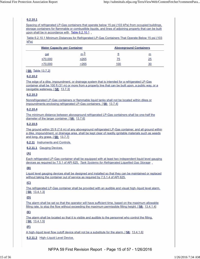
6.2.10.1
Spacing of refrigerated LP-Gas containers that operate below 15 psi (103 kPa) from occupied buildings,storage containers for flammable or combustible liquids, and lines of adjoining property that can be builtupon shall be in accordance with Table 6.2.10.1 .
Table 6.2.10.1 Minimum Distances for Refrigerated LP-Gas Containers That Operate Below 15 psi (103kPa)
Water Capacity per Container Aboveground Containers
gal m 3 ft m
≤70,000 ≤265 75 25
>70,000 >265 100 30
[ 58: Table 13.7.2]
6.2.10.2
The edge of a dike, impoundment, or drainage system that is intended for a refrigerated LP-Gascontainer shall be 100 ft (31 m) or more from a property line that can be built upon, a public way, or anavigable waterway. [ 58: 13.7.3]
6.2.10.3
Nonrefrigerated LP-Gas containers or flammable liquid tanks shall not be located within dikes orimpoundments enclosing refrigerated LP-Gas containers. [ 58: 13.7.4]
6.2.10.4
The minimum distance between aboveground refrigerated LP-Gas containers shall be one-half thediameter of the larger container. [ 58: 13.7.6]
6.2.10.5
The ground within 25 ft (7.6 m) of any aboveground refrigerated LP-Gas container, and all ground withina dike, impoundment, or drainage area, shall be kept clear of readily ignitable materials such as weedsand long, dry grass. [ 58: 13.7.7]
6.2.11 Instruments and Controls.
6.2.11.1 Gauging Devices.
(A)
Each refrigerated LP-Gas container shall be equipped with at least two independent liquid level gaugingdevices as required by 7.5.1 of API 625, Tank Systems for Refrigerated Liquefied Gas Storage .
(B)
Liquid level gauging devices shall be designed and installed so that they can be maintained or replacedwithout taking the container out of service as required by 7.5.1.4 of API 625.
(C)
The refrigerated LP-Gas container shall be provided with an audible and visual high–liquid level alarm.[ 58: 13.4.1.3]
(D)
The alarm shall be set so that the operator will have sufficient time, based on the maximum allowablefilling rate, to stop the flow without exceeding the maximum permissible filling height. [ 58: 13.4.1.4]
(E)
The alarm shall be located so that it is visible and audible to the personnel who control the filling.[ 58: 13.4.1.5]
(F)
A high–liquid level flow cutoff device shall not be a substitute for the alarm. [ 58: 13.4.1.6]
6.2.11.2 High–Liquid Level Device.
National Fire Protection Association Report http://submittals.nfpa.org/TerraViewWeb/ContentFetcher?commentPara...
15 of 56 1/26/2016 7:34 AM
NFPA 59 First Revision Report - Page 15 of 57 - 1/26/2016
(A)
The refrigerated LP-Gas container shall be equipped with a high-high–liquid level flow cutoff device thatis independent from all gauges. [ 58: 13.4.1.7]
(B)
Where refrigerated LP-Gas containers of 70,000 gal (265 m3) or less are attended during the fillingoperation, they shall be equipped with either liquid try cocks or a high–liquid level alarm, and manualflow cutoff shall be permitted. [ 58: 13.4.1.8]
(C)
Each refrigerated LP-Gas container shall be provided with temperature-indicating devices that assist incontrolling cooldown rates when placing the tank in service and monitoring product temperatures duringoperations. [ 58: 13.4.1.9]
6.2.11.3 Pressure and Vacuum Control.
(A)
Each refrigerated LP-Gas container shall be equipped with at least two independent pressure-indicatinginstruments as required by 7.5.5 of API 625, Tank Systems for Refrigerated Liquefied Gas Storage .
(B)
Provisions shall be made to maintain the container pressure within the limits set by the designspecifications by releasing or admitting gas as needed. [ 58: 13.4.2.1]
(C)
Provision for admission and release of gas shall be by any means compatible with the gas-handlingfacilities in the plant. [ 58: 13.4.2.2]
(D)
The option of gas admission, or other gas or vapor, if so designed, through the vacuum relief valves inaccordance with 7.2.3 of API 620, Design and Construction of Large, Welded, Low-Pressure StorageTanks , shall not be permitted.
6.2.12 Impoundment.
6.2.12.1
Each refrigerated LP-Gas container shall be located within an impoundment that complies with 6.3.8 .
6.2.12.2
Enclosed drainage channels for LP-Gas shall be prohibited.
6.2.12.3
Impoundment for refrigerated LP-Gas containers shall have a volumetric holding capacity with anallowance made for the displacement of snow accumulation, other containers, or equipment that isequal to the total liquid volume of the largest container served, assuming that container is filled to thehigh–liquid level flow cutoff device.
6.2.12.4
Where more than one container is installed in a single impoundment, and if an outside container wall isused as a spill containment dike, the material shall be selected to withstand exposure to thetemperature of refrigerated LP-Gas liquid.
6.2.12.5
Impoundment structures and any penetrations thereof shall be designed to withstand the full hydrostatichead of the impounded LP-Gas, the effects of the product composition, and the resulting autorefrigeration temperatures.
6.2.12.6
Impoundment structures shall also be nonporous and resistant to natural forces such as wind, rain, andfire.
6.2.12.7
Provisions shall be made to clear rain or other water from the impounding area.
National Fire Protection Association Report http://submittals.nfpa.org/TerraViewWeb/ContentFetcher?commentPara...
16 of 56 1/26/2016 7:34 AM
NFPA 59 First Revision Report - Page 16 of 57 - 1/26/2016
(A)
Where automatically controlled sump pumps are used, they shall be equipped with an automatic shutoffdevice that prevents their operation when either of the following occurs:
(1) They are exposed to the flash temperature of the liquid LP-Gas.
(2) Flammable vapors in excess of 25 percent of the lower flammable limit are detected within theimpoundment area.
(B)
Gravity drainage utilizing piping penetrations through or below impoundment dikes shall not bepermitted.
6.2.12.8
If the container impounding area is an earthen dike system, the area topography of the impounding areafloor shall be graded away from the container to prevent the accumulation of liquid under or around thecontainer.
(A)
The grading shall move the spilled liquid to the toe of the dike system and as far away from thecontainer as possible.
(B)
The grading shall move the spilled liquid to a sub-impoundment basin that is capable of holding thequantity of liquid spilled from a line rupture, a flange leak, or a source other than container failure.
(C)
The duration of the incident shall be the amount of time that automatic systems or plant personnel couldaffect emergency procedures and stop the leak, and the sub-impoundment basin shall be located as faraway from the container as possible.
6.2.13 Inspection and Testing of Refrigerated LP-Gas Containers and Systems.
6.2.13.1
During construction and prior to the initial operation or commissioning, each refrigerated LP-Gascontainer and system shall be inspected or tested in accordance with the provisions of this code andAPI 625, Tank Systems for Refrigerated Liquefied Gas Storage ; API 620, Design and Construction ofLarge, Welded, Low-Pressure Storage Tanks ; ACI 376, Code Requirements for Design andConstruction of Concrete Structures for the Containment of Refrigerated Liquefied Gases ; and ASMEB31.3, Process Piping .
6.2.13.2
The inspections or tests required shall be conducted by the operator or by a third-party engineering,scientific, recognized insurance, or inspection organization.
6.2.13.3
Each inspector shall be qualified in accordance with the code or standard that is applicable to the test orinspection being performed.
6.2.13.4
After acceptance tests are completed, there shall be no field welding on the LP-Gas containers exceptwhere allowed by the code under which the container was fabricated.
6.2.13.5
Retesting shall be required only if it tests the element affected and is necessary to demonstrate theadequacy of the repair or modification.
6.2.14 Container Design Temperature and Pressure.
[ 58: 12.1.2]
National Fire Protection Association Report http://submittals.nfpa.org/TerraViewWeb/ContentFetcher?commentPara...
17 of 56 1/26/2016 7:34 AM
NFPA 59 First Revision Report - Page 17 of 57 - 1/26/2016
6.2.14.1
The maximum allowable working pressure shall include a margin above the operating pressure.
6.2.14.2
The design pressure of ASME containers shall include a minimum 5 percent of the absolute vaporpressure of the LP-Gas at the design storage temperature. The margin (both positive and vacuum) forlow-pressure API Standard 620, Design and Construction of Large, Welded, Low-Pressure StorageTanks , vessels shall include the following:
Control range of the boil-off handling system
Effects of flash or vapor collapse during filling operations
Flash that can result from withdrawal pump recirculation
Normal range of barometric pressure changes
[ 58: 12.1.2.1]
6.2.14.3
The design temperature for those parts of a refrigerated LP-Gas container that are in contact with theliquid or refrigerated vapor shall be equal to or lower than the boiling point of the product to be stored atatmospheric pressure. A temperature allowance shall be made for the composition of the liquid to bestored when it is flashed into the vapor space of a tank. [ 58: 12.1.2.2]
6.3 Refrigerated Containers Designed to Operate Above 15 psi (103 kPa).
6.3.1
Containers designed to operate above 15 psi (103 kPa) shall be in accordance with the ASME Boilerand Pressure Vessel Code , Section VIII, and any additional provisions of this chapter.
6.3.1.1
Construction using joint efficiencies listed in Table UW 12, Column C , of the ASME Boiler andPressure Vessel Code shall not be permitted.
6.3.2 Construction and Design of Refrigerated Containers.
6.3.2.1 Container Material and Construction Requirements.
6.3.2.2
Materials that maintain their integrity at the boiling temperature of the liquid stored and are used inrefrigerated containers shall be selected from those included in the ASME Boiler and Pressure VesselCode , Section VIII.
6.3.2.3
All new construction shall incorporate either an internal valve or a back check valve on any bottom orside penetrations that communicate with the liquid space of the container.
6.3.2.4
Emergency shutoff valves shall be incorporated into facility emergency shutdown systems and becapable of being operated remotely.
6.3.3 Container Design Temperature and Pressure.
[ 58: 12.1.2]
6.3.3.1
The maximum allowable working pressure shall include a margin above the operating pressure.
National Fire Protection Association Report http://submittals.nfpa.org/TerraViewWeb/ContentFetcher?commentPara...
18 of 56 1/26/2016 7:34 AM
NFPA 59 First Revision Report - Page 18 of 57 - 1/26/2016
6.3.3.2
The design pressure of ASME containers shall include a minimum 5 percent of the absolute vaporpressure of the LP-Gas at the design storage temperature. The margin (both positive and vacuum) forlow-pressure API Standard 620, Design and Construction of Large, Welded, Low-Pressure StorageTanks , vessels shall include the following:
Control range of the boil-off handling system
Effects of flash or vapor collapse during filling operations
Flash that can result from withdrawal pump recirculation
Normal range of barometric pressure changes
[ 58: 12.1.2.1]
6.3.3.3
The design temperature for those parts of a refrigerated LP-Gas container that are in contact with theliquid or refrigerated vapor shall be equal to or lower than the boiling point of the product to be stored atatmospheric pressure. A temperature allowance shall be made for the composition of the liquid to bestored when it is flashed into the vapor space of a tank. [ 58: 12.1.2.2]
6.3.3.4
A temperature allowance shall be made for the composition of the liquid to be stored when it is flashedinto the vapor space of a tank. [ 58: 13.1.2.2(B)]
6.3.4 Marking on Refrigerated LP-Gas Containers.
[ 58: 12.2]
6.3.4.1
Each refrigerated LP-Gas container shall be identified by the attachment of a nameplate located either onthe container or in a visible location. [58:12 13 .2.1]
6.3.4.2
The nameplate shall be in accordance with API Standard 620, Design and Construction of Large,Welded, Low-Pressure Storage Tanks, Section 6. [ 58: 12.2.2]
6.3.5 Container Installation.
[ 58: 12.3]
6.3.5.1 Wind Loading.
[ 58: 12.3.1]
(A)
The design wind loading on refrigerated LP-Gas containers shall be in accordance with the projected areaat various height zones above ground in accordance with ASCE/SEI 7–10 , Minimum Design Loads forBuildings and Other Structures. [58:12 13 .3.1.1]
(B)
Design wind speeds shall be based on a mean occurrence interval of 100 years. [58:12 13 .3.1.2]
6.3.5.2 Seismic Loading.
[ 58: 12.3.2]
(A)
The design seismic loading on refrigerated LP-Gas containers shall be in accordance with ASCE/SEI 7,Minimum Design Loads for Buildings and Other Structures. [58:12 13 .3.2.1]
(B)
A seismic analysis of the proposed installation shall be made that meets the approval of the authorityhaving jurisdiction. [58:12 13 .3.2.2]
6.3.5.3 Piping.
[ 58: 12.3.3]
National Fire Protection Association Report http://submittals.nfpa.org/TerraViewWeb/ContentFetcher?commentPara...
19 of 56 1/26/2016 7:34 AM
NFPA 59 First Revision Report - Page 19 of 57 - 1/26/2016
6.3.5.3.1
All piping that is part of a refrigerated LP-Gas container and refrigerated LP-Gas systems, includingtransfer and process piping, shall be in accordance with ASME B31.3, Process Piping. [58:12 13 .3.3.1]
6.3.5.3.2
The container piping shall include the following:
(1) All piping internal to the container
(2) All piping within the insulation spaces
(3) All external piping attached or connected to the container up to the first circumferential external jointof the piping
[58:12.3.3.2 13.3.3.2 ]
6.3.5.3.3
Inert gas purge systems wholly within the insulation spaces shall be exempt from the provision in6.3.5.3.1. [58:12 13 .3.3.3]
6.3.6 Foundations.
[ 58: 12.3.4]
6.3.6.1
Refrigerated Foundations for refrigerated aboveground containers shall be designed and installed onfoundations that have been engineered for site soil conditions and loadings. [ 58: 12.3.4.1]
6.3.6.2
Prior to the start of design and construction of the foundation, a subsurface investigation shall beconducted by a soils engineer. Foundations shall be designed by an engineer who is experienced infoundations and soils. [ 58: 12.3.4.2]
6.3.6.3
Foundations shall be designed by an engineer who is experienced in foundations and soils.[ 58: 13.3.4.2(B)]
6.3.6.4
Where product storage is at less than 30°F (−1.1°C), the foundation and the container bottom shallcomply with the following:
(1) The foundation design and the container bottom insulation shall prevent damage to the containerfrom frost heave.
(2) If the refrigerated LP-Gas container under bottom foundation and insulation are in contact with thesoil, and the soil temperature can be less than 32°F (0°C), a heating system shall be installed toprevent the soil temperature from falling below 32°F (0°C).
(3) The under-container heating system shall be designed to allow both functional and performancemonitoring.
(4) The under-container temperature shall be observed and logged at least weekly.
(5) Where the foundation has a discontinuity, such as bottom piping, the heating system in that zoneshall be designed for the discontinuity.
(6) The under-container heating system shall be installed so that any heating elements or temperaturesensors used for control can be replaced while the container is in service.
(7) Provisions shall be incorporated to minimize the effects of moisture accumulation in the conduit andother forms of deterioration within the conduit or heating element.
[58:12 13 .3.4.3]
6.3.6.5
The refrigerated LP-Gas container foundation shall be periodically monitored for settlement during the lifeof the facility. [58:12 13 .3.4.4]
National Fire Protection Association Report http://submittals.nfpa.org/TerraViewWeb/ContentFetcher?commentPara...
20 of 56 1/26/2016 7:34 AM
NFPA 59 First Revision Report - Page 20 of 57 - 1/26/2016
6.3.6.6
The monitoring shall include construction, hydrostatic testing, commissioning, and operation.[58:12 13 .3.4.5]
6.3.6.7
Any settlement in excess of that anticipated in the design shall be investigated, and corrective action shallbe taken if appropriate. [58:12 13 .3.4.6]
6.3.6.8
For a container having a double wall design, the bottom of the outer wall and the refrigerated LP-Gascontainer under-container insulation shall be above the groundwater table or protected from contact withgroundwater at all times. It For a container having a double wall design, the bottom of the outer wall andthe refrigerated LP-Gas container under-container insulation shall be above the groundwater table orprotected from contact with groundwater at all times, and it shall also be protected from floodwaters.[58:12 13 .3.4.7]
6.3.6.9
Where two or more containers are sited in a common dike, the container foundations shall be constructedof material resistant to the effects of refrigerated LP-Gas and the temperatures to which they will beexposed. [ 58: 12.3.4.8] [ 58: 13.3.4.8]
6.3.6.10
If the foundation of a refrigerated LP-Gas container is designed to provide air circulation in lieu of aheating system, the foundation and insulating material under the bottom of the container shall beconstructed of materials that are resistant to the effects of refrigerated LP-Gas and the temperatures towhich they will be exposed. [ 58: 12.3.4.9] [ 58: 13.3.4.9]
6.3.6.11
The material in contact with the bottom of the container shall be selected to minimize corrosion.[58:12 13 .3.4.10]
6.3.7 Refrigerated LP-Gas Container Instruments and Controls.
[ 58: 12.4]
6.3.7.1 Gauging Devices.
[ 58: 12.4.1]
(A)
Each refrigerated LP-Gas container shall be equipped with at least two independent liquid level gaugingdevices. [58:12 13 .4.1.1]
(B)
Liquid level gauging devices shall be installed so that they can be replaced without taking the containerout of service. [58:12 13 .4.1.2]
6.3.7.1.3
The refrigerated LP-Gas container shall be provided with an audible and visual high–liquid level alarm.[ 58: 12.4.1.3]
6.3.7.1.4
The alarm shall be set so that the operator will have sufficient time, based on the maximum allowablefilling rate, to stop the flow without exceeding the maximum permissible filling height. [ 58: 12.4.1.4]
6.3.7.1.5
The alarm shall be located so that it is visible and audible to the personnel who control the filling.[ 58: 12.4.1.5]
(C)
The refrigerated LP-Gas container shall be provided with an audible and visual high–liquid level alarm.[ 58: 13.4.1.3]
National Fire Protection Association Report http://submittals.nfpa.org/TerraViewWeb/ContentFetcher?commentPara...
21 of 56 1/26/2016 7:34 AM
NFPA 59 First Revision Report - Page 21 of 57 - 1/26/2016
(D)
The alarm shall be set so that the operator will have sufficient time, based on the maximum allowablefilling rate, to stop the flow without exceeding the maximum permissible filling height. [ 58: 13.4.1.4]
(E)
The alarm shall be located so that it is visible and audible to the personnel who control the filling.[ 58: 13.4.1.5]
(F)
A high–liquid level flow cutoff device shall not be a substitute for the alarm. [58:12 13 .4.1.6]
6.3.7.2 High–Liquid Level Device.
(A)
The refrigerated LP-Gas container shall be equipped with a high-high–liquid level flow cutoff device that isindependent from all gauges. [58:12 13 .4.1.7]
(B)
Where refrigerated LP-Gas containers of 70,000 gal (265 m3) or less are attended during the fillingoperation, they shall be equipped with either liquid trycocks or a high–liquid level alarm, and manual flowcutoff shall be permitted. [58:12 13 .4.1.8]
(C)
Each refrigerated LP-Gas container shall be provided with temperature-indicating devices that assist incontrolling cooldown rates when placing the tank in service and monitoring product temperatures duringoperations. [ 58: 12.4.1.9] [ 58: 13.4.1.9]
6.3.7.3 Pressure and Vacuum Control.
[ 58: 12.4.2]
(A)
Provisions shall be made to maintain the container pressure within the limits set by the designspecifications by releasing or admitting gas as needed. [ 58: 13.4.2.1]
(B)
Provision for admission and release of gas shall be by any means compatible with the gas-handlingfacilities in the plant. [ 58: 12.4.2.1] [ 58: 13.4.2.2]
(C)
The option of gas admission (or other gas or vapor if so designed) through the vacuum relief valvesprovided in 7.2.3 of API Standard 620, Design and Construction of Large, Welded, Low-PressureStorage Tanks, paragraph 7.2.3, shall not be permitted.
6.3.8 Refrigerated LP-Gas Container Impoundment.
[ 58: 12.5]
6.3.8.1
Each refrigerated LP-Gas container shall be located within an impoundment that complies with Section6.3.86.6 . [58:12 13 .5.1]
6.3.8.2
Enclosed drainage channels for LP-Gas shall be prohibited. [58:12 13 .5.2]
6.3.8.3
Impoundment for refrigerated LP-Gas containers shall have a volumetric holding capacity, with anallowance made for the displacement of snow accumulation, other containers, or equipment that is equalto the total liquid volume of the largest container served, assuming that container is full to the high–liquidlevel flow cutoff device. [58:12 13 .5.4]
National Fire Protection Association Report http://submittals.nfpa.org/TerraViewWeb/ContentFetcher?commentPara...
22 of 56 1/26/2016 7:34 AM
NFPA 59 First Revision Report - Page 22 of 57 - 1/26/2016
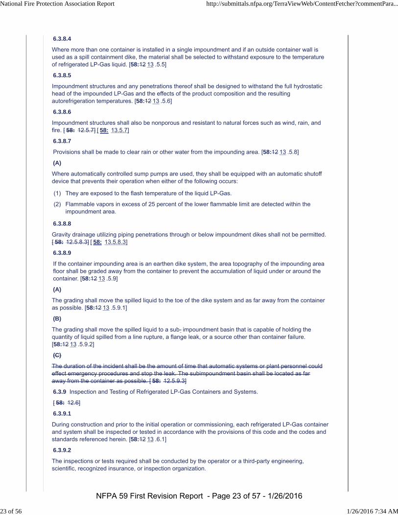
6.3.8.4
Where more than one container is installed in a single impoundment and if an outside container wall isused as a spill containment dike, the material shall be selected to withstand exposure to the temperatureof refrigerated LP-Gas liquid. [58:12 13 .5.5]
6.3.8.5
Impoundment structures and any penetrations thereof shall be designed to withstand the full hydrostatichead of the impounded LP-Gas and the effects of the product composition and the resultingautorefrigeration temperatures. [58:12 13 .5.6]
6.3.8.6
Impoundment structures shall also be nonporous and resistant to natural forces such as wind, rain, andfire. [ 58: 12.5.7] [ 58: 13.5.7]
6.3.8.7
Provisions shall be made to clear rain or other water from the impounding area. [58:12 13 .5.8]
(A)
Where automatically controlled sump pumps are used, they shall be equipped with an automatic shutoffdevice that prevents their operation when either of the following occurs:
(1) They are exposed to the flash temperature of the liquid LP-Gas.
(2) Flammable vapors in excess of 25 percent of the lower flammable limit are detected within theimpoundment area.
6.3.8.8
Gravity drainage utilizing piping penetrations through or below impoundment dikes shall not be permitted.[ 58: 12.5.8.3] [ 58: 13.5.8.3]
6.3.8.9
If the container impounding area is an earthen dike system, the area topography of the impounding areafloor shall be graded away from the container to prevent the accumulation of liquid under or around thecontainer. [58:12 13 .5.9]
(A)
The grading shall move the spilled liquid to the toe of the dike system and as far away from the containeras possible. [58:12 13 .5.9.1]
(B)
The grading shall move the spilled liquid to a sub- impoundment basin that is capable of holding thequantity of liquid spilled from a line rupture, a flange leak, or a source other than container failure.[58:12 13 .5.9.2]
(C)
The duration of the incident shall be the amount of time that automatic systems or plant personnel couldeffect emergency procedures and stop the leak. The subimpoundment basin shall be located as faraway from the container as possible. [ 58: 12.5.9.3]
6.3.9 Inspection and Testing of Refrigerated LP-Gas Containers and Systems.
[ 58: 12.6]
6.3.9.1
During construction and prior to the initial operation or commissioning, each refrigerated LP-Gas containerand system shall be inspected or tested in accordance with the provisions of this code and the codes andstandards referenced herein. [58:12 13 .6.1]
6.3.9.2
The inspections or tests required shall be conducted by the operator or a third-party engineering,scientific, recognized insurance, or inspection organization.
National Fire Protection Association Report http://submittals.nfpa.org/TerraViewWeb/ContentFetcher?commentPara...
23 of 56 1/26/2016 7:34 AM
NFPA 59 First Revision Report - Page 23 of 57 - 1/26/2016
6.3.9.3
Each inspector shall be qualified in accordance with the code or standard that is applicable to the test orinspection being performed. [ 58: 12.6.3] [ 58: 13.6.3]
6.3.9.4
After acceptance tests are completed, there shall be no field welding on the LP-Gas containers exceptwhere allowed by the code under which the container was fabricated. [58:12 13 .6.4]
6.3.9.5
Retesting shall be required only if the retest tests the element affected and is necessary to demonstratethe adequacy of the repair or modification. [58:12 13 .6.5]
6.3.10 Container Siting.
[ 58: 12.7]
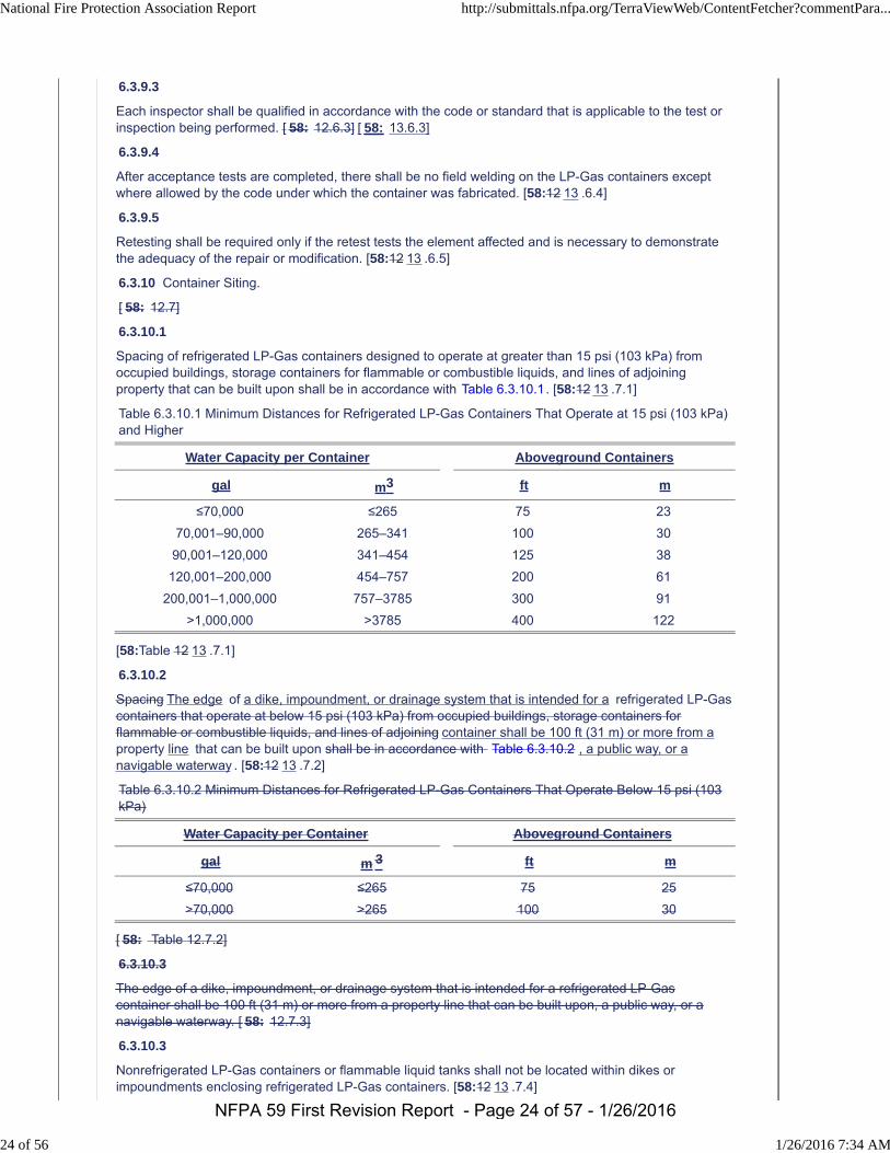
6.3.10.1
Spacing of refrigerated LP-Gas containers designed to operate at greater than 15 psi (103 kPa) fromoccupied buildings, storage containers for flammable or combustible liquids, and lines of adjoiningproperty that can be built upon shall be in accordance with Table 6.3.10.1. [58:12 13 .7.1]
Table 6.3.10.1 Minimum Distances for Refrigerated LP-Gas Containers That Operate at 15 psi (103 kPa)and Higher
Water Capacity per Container Aboveground Containers
gal m3 ft m
≤70,000 ≤265 75 23
70,001–90,000 265–341 100 30
90,001–120,000 341–454 125 38
120,001–200,000 454–757 200 61
200,001–1,000,000 757–3785 300 91
>1,000,000 >3785 400 122
[58:Table 12 13 .7.1]
6.3.10.2
Spacing The edge of a dike, impoundment, or drainage system that is intended for a refrigerated LP-Gascontainers that operate at below 15 psi (103 kPa) from occupied buildings, storage containers forflammable or combustible liquids, and lines of adjoining container shall be 100 ft (31 m) or more from aproperty line that can be built upon shall be in accordance with Table 6.3.10.2 , a public way, or anavigable waterway . [58:12 13 .7.2]
Table 6.3.10.2 Minimum Distances for Refrigerated LP-Gas Containers That Operate Below 15 psi (103kPa)
Water Capacity per Container Aboveground Containers
gal m 3 ft m
≤70,000 ≤265 75 25
>70,000 >265 100 30
[ 58: Table 12.7.2]
6.3.10.3
The edge of a dike, impoundment, or drainage system that is intended for a refrigerated LP-Gascontainer shall be 100 ft (31 m) or more from a property line that can be built upon, a public way, or anavigable waterway. [ 58: 12.7.3]
6.3.10.3
Nonrefrigerated LP-Gas containers or flammable liquid tanks shall not be located within dikes orimpoundments enclosing refrigerated LP-Gas containers. [58:12 13 .7.4]
National Fire Protection Association Report http://submittals.nfpa.org/TerraViewWeb/ContentFetcher?commentPara...
24 of 56 1/26/2016 7:34 AM
NFPA 59 First Revision Report - Page 24 of 57 - 1/26/2016
6.3.10.4
Refrigerated LP-Gas containers shall not be installed one above the other. [58:12 13 .7.5]
6.3.10.5
The minimum distance between aboveground refrigerated LP-Gas containers shall be one-half thediameter of the larger container. [58:12 13 .7.6]
6.3.10.6
The ground within 25 ft (7.6 m) of any aboveground refrigerated LP-Gas container, and all ground within adike, impoundment, or drainage area, shall be kept clear of readily ignitible ignitable materials such asweeds and long, dry grass. [58:12 13 .7.7]
Supplemental Information
File Name Description
Chapter_6_EN_10.29.15.doc New Chapter 6 incorporating PI 24 and PI 58.
Submitter Information Verification
Submitter Full Name: Eric Nette
Organization: [ Not Specified ]
Street Address:
City:
State:
Zip:
Submittal Date: Thu Oct 29 13:43:45 CDT 2015
Committee Statement
CommitteeStatement:
In the 1998 edition of NFPA 59, NFPA 59 began extracting the entire refrigerated container sectionfrom NFPA 58. Prior to the 1998 edition of NFPA 59, the NFPA 59 standard included very similar textthat was in NFPA 58 but it was not officially extracted from NFPA 58. Over the last several years, thestandards development organizations have developed a series of including one new standard (API625) and revising two existing standards (API 620 and ACI 376) such that a low pressure refrigeratedstorage container must apply all three standards to design, engineer, construct, examine and test anew storage tank.
ResponseMessage:
Public Input No. 58-NFPA 59-2015 [Chapter 6]
National Fire Protection Association Report http://submittals.nfpa.org/TerraViewWeb/ContentFetcher?commentPara...
25 of 56 1/26/2016 7:34 AM
NFPA 59 First Revision Report - Page 25 of 57 - 1/26/2016
First Revision No. 5-NFPA 59-2015 [ Section No. 7.1.11 ]
7.1.11
Piping outside buildings shall be supported and protected against physical damage and corrosion.
Submitter Information Verification
Submitter Full Name: Eric Nette
Organization: [ Not Specified ]
Street Address:
City:
State:
Zip:
Submittal Date: Wed Oct 28 12:33:27 EDT 2015
Committee Statement
Committee Statement: All piping should be protected, not just piping outside buildings.
Response Message:
Public Input No. 30-NFPA 59-2015 [Section No. 7.1.11]
National Fire Protection Association Report http://submittals.nfpa.org/TerraViewWeb/ContentFetcher?commentPara...
26 of 56 1/26/2016 7:34 AM
NFPA 59 First Revision Report - Page 26 of 57 - 1/26/2016
First Revision No. 23-NFPA 59-2015 [ Section No. 7.2.5 ]
7.2.5
All liquid and vapor connections on containers, other than pressure relief valves, liquid level gaugingdevices, and openings not larger than No. 54 drill size [0.055 in. (1.4 mm)], as covered in 7.2.6 and7.4.3, shall be equipped with one of the following:
(1) A back-pressure check valve and either a manual valve or an emergency shutoff valve
(2) An excess-flow valve with a fail-closed hydraulic or pneumatically actuated valve in compliance withAPI 607, Fire Test for Soft-Seated Quarter-Turn Valves; API 6FA, Specifications for Fire Tests forValves; or the equivalent, equipped for remote closure and automatic shutoff using thermal (fire)actuation where the thermal element is installed in compliance with 7.1.5
(3) A quick-acting internal valve incorporating the means of closing specified in 7.1.4
Submitter Information Verification
Submitter Full Name: Eric Nette
Organization: [ Not Specified ]
Street Address:
City:
State:
Zip:
Submittal Date: Thu Oct 29 17:11:35 CDT 2015
Committee Statement
Committee Statement: This change will provide more commonly understood dimensions.
Response Message:
Public Input No. 27-NFPA 59-2015 [Section No. 7.2.5]
National Fire Protection Association Report http://submittals.nfpa.org/TerraViewWeb/ContentFetcher?commentPara...
27 of 56 1/26/2016 7:34 AM
NFPA 59 First Revision Report - Page 27 of 57 - 1/26/2016
First Revision No. 24-NFPA 59-2015 [ Section No. 7.2.6 ]
7.2.6
Openings from a container or through fittings attached directly on the container to which pressure gaugeconnection is made shall not be required to be equipped with an excess-flow valve if such openings arenot larger than a No. 54 drill size [0.055 in. (1.4 mm)] .
Submitter Information Verification
Submitter Full Name: Eric Nette
Organization: [ Not Specified ]
Street Address:
City:
State:
Zip:
Submittal Date: Thu Oct 29 17:17:08 CDT 2015
Committee Statement
Committee Statement: This change will provide more commonly understood dimensions.
Response Message:
Public Input No. 31-NFPA 59-2015 [Section No. 7.2.6]
National Fire Protection Association Report http://submittals.nfpa.org/TerraViewWeb/ContentFetcher?commentPara...
28 of 56 1/26/2016 7:34 AM
NFPA 59 First Revision Report - Page 28 of 57 - 1/26/2016
First Revision No. 25-NFPA 59-2015 [ Section No. 7.2.8 ]
7.2.8
Excess-flow valves shall be designed with a bypass, not to exceed a No. 60 drill size [0.040 in. (1.02mm)] opening, to allow equalization of pressures.
Submitter Information Verification
Submitter Full Name: Eric Nette
Organization: [ Not Specified ]
Street Address:
City:
State:
Zip:
Submittal Date: Thu Oct 29 17:20:01 CDT 2015
Committee Statement
Committee Statement: This change will provide more commonly understood dimensions.
Response Message:
Public Input No. 32-NFPA 59-2015 [Section No. 7.2.8]
National Fire Protection Association Report http://submittals.nfpa.org/TerraViewWeb/ContentFetcher?commentPara...
29 of 56 1/26/2016 7:34 AM
NFPA 59 First Revision Report - Page 29 of 57 - 1/26/2016

First Revision No. 15-NFPA 59-2015 [ Section No. 7.4.1 ]
7.4.1
Each nonrefrigerated storage system container shall be equipped with an approved liquid level gaugingdevice in accordance with the following:
(1) If the liquid level gauging device is a float gauge or a pressure differential gauge, the container alsoshall be provided with an auxiliary gauging device, such as a fixed liquid level gauge, slip tube, rotarygauge, or similar device.
(2) Unlisted gauge glasses of the columnar type shall not be permitted.
Submitter Information Verification
Submitter Full Name: Eric Nette
Organization: [ Not Specified ]
Street Address:
City:
State:
Zip:
Submittal Date: Thu Oct 29 14:21:50 CDT 2015
Committee Statement
Committee Statement: The container must be equipped with the device, not the "system".
Response Message:
Public Input No. 33-NFPA 59-2015 [Section No. 7.4.1]
National Fire Protection Association Report http://submittals.nfpa.org/TerraViewWeb/ContentFetcher?commentPara...
30 of 56 1/26/2016 7:34 AM
NFPA 59 First Revision Report - Page 30 of 57 - 1/26/2016
First Revision No. 26-NFPA 59-2015 [ Section No. 7.4.3 ]
7.4.3
Gauging devices that require bleeding of the product to the atmosphere, such as the rotary tube, fixedliquid level gauge, and slip tube, shall be designed so that the bleed valve maximum opening is not largerthan a No. 54 drill size [0.055 in. (1.4 mm)] , unless provided with an excess-flow valve.
Submitter Information Verification
Submitter Full Name: Eric Nette
Organization: [ Not Specified ]
Street Address:
City:
State:
Zip:
Submittal Date: Thu Oct 29 17:23:30 CDT 2015
Committee Statement
Committee Statement: This change will provide more commonly understood dimensions.
Response Message:
Public Input No. 34-NFPA 59-2015 [Section No. 7.4.3]
National Fire Protection Association Report http://submittals.nfpa.org/TerraViewWeb/ContentFetcher?commentPara...
31 of 56 1/26/2016 7:34 AM
NFPA 59 First Revision Report - Page 31 of 57 - 1/26/2016
First Revision No. 6-NFPA 59-2015 [ Section No. 7.10.4.4 ]
7.10.4.4
All new installations and, by December 31, 2005, all existing installations and existing installations shallhave at least two clearly identified and easily accessible manually operated remote emergency shutoffdevices. One shutoff device shall be located not less than 20 ft (6.1 m) nor more than 100 ft (30.5 m) inthe path of egress from the emergency shutoff valve.
Submitter Information Verification
Submitter Full Name: Eric Nette
Organization: [ Not Specified ]
Street Address:
City:
State:
Zip:
Submittal Date: Wed Oct 28 12:35:13 EDT 2015
Committee Statement
Committee Statement: Date has passed and is no longer needed – removal will add clarity to the code.
Response Message:
Public Input No. 37-NFPA 59-2015 [Section No. 7.10.4.4]
National Fire Protection Association Report http://submittals.nfpa.org/TerraViewWeb/ContentFetcher?commentPara...
32 of 56 1/26/2016 7:34 AM
NFPA 59 First Revision Report - Page 32 of 57 - 1/26/2016
First Revision No. 7-NFPA 59-2015 [ Section No. 9.5.1.3 ]
9.5.1.3
If the heat-supplying device source serving an indirect vaporizer is installed outdoors and utilizes anoncombustible heat transfer fluid, such as steam, water, or a water–glycol mixture, it shall be installedoutdoors the device or the housing in which it is installed shall be located at least 50 ft (15 m) from otherLP-Gas facilities and operations or shall comply with one of the following:
(1) If installed within a structure, the structure shall comply with Chapter 8.
If installed outdoors, the heat-supplying device or the housing in which it is installed shall be locatedat least 50 ft (15 m) from other LP-Gas facilities and operations.
(2) If the heat source of an indirect vaporizer is gas-fired and is located within 15 ft (4.6 m) of thevaporizer, the vaporizer and its heat source shall be installed as a direct-fired vaporizer and shall besubject to the requirements of 9.5.2.
(3) A source of heat for an indirect vaporizer shall be permitted to be installed in an industrial occupancycomplying with Chapter 40 of NFPA 101, Life Safety Code , and Section 9.3 of NFPA 54, NationalFuel Gas Code , where the heat transfer fluid is steam or hot water and is not recirculated and abackflow preventer is installed between the vaporizer and the heat source.
(4) If the heat transfer fluid is recirculated after leaving the vaporizer, a phase separator shall be installedwith the gas vented to a safe location.
Submitter Information Verification
Submitter Full Name: Eric Nette
Organization: [ Not Specified ]
Street Address:
City:
State:
Zip:
Submittal Date: Wed Oct 28 12:46:25 EDT 2015
Committee Statement
CommitteeStatement:
Deleting 9.5.1.3 (2), and incorporating the text in with the requirements for outsideinstallations is grammatically correct and adds clarity.
ResponseMessage:
Public Input No. 39-NFPA 59-2015 [Section No. 9.5.1.3]
National Fire Protection Association Report http://submittals.nfpa.org/TerraViewWeb/ContentFetcher?commentPara...
33 of 56 1/26/2016 7:34 AM
NFPA 59 First Revision Report - Page 33 of 57 - 1/26/2016
First Revision No. 39-NFPA 59-2016 [ Section No. 10.2.2.2 ]
10.2.2.2
Containers of 40,000 gal (151 m3) or more water capacity shall be equipped with either a spring-loadedpressure relief valve or a pilot-operated pressure relief valve, as follows:
(1) The pilot Pilot -operated relief valve valves shall be combined with, and controlled by, aself-actuated, direct, spring-loaded pilot valve valves that complies comply with Table 10.2.2.1.
(2) The use of a pilot Pilot -operated pressure relief valve valves shall be approved inspected andmaintained by persons with training and experience .
(3) Pilot-operated pressure relief valves shall be inspected and maintained by persons with training andexperience, and shall be tested for operation at intervals not exceeding 5 years.
[58:5.7. 9. 2.5(B)]
Submitter Information Verification
Submitter Full Name: Sonia Barbosa
Organization: [ Not Specified ]
Street Address:
City:
State:
Zip:
Submittal Date: Fri Jan 22 14:09:16 EST 2016
Committee Statement
Committee Statement: Updating extracted text.
Response Message:
National Fire Protection Association Report http://submittals.nfpa.org/TerraViewWeb/ContentFetcher?commentPara...
34 of 56 1/26/2016 7:34 AM
NFPA 59 First Revision Report - Page 34 of 57 - 1/26/2016
First Revision No. 40-NFPA 59-2016 [ Section No. 10.2.3 ]
National Fire Protection Association Report http://submittals.nfpa.org/TerraViewWeb/ContentFetcher?commentPara...
35 of 56 1/26/2016 7:34 AM
NFPA 59 First Revision Report - Page 35 of 57 - 1/26/2016
10.2.3
National Fire Protection Association Report http://submittals.nfpa.org/TerraViewWeb/ContentFetcher?commentPara...
36 of 56 1/26/2016 7:34 AM
NFPA 59 First Revision Report - Page 36 of 57 - 1/26/2016
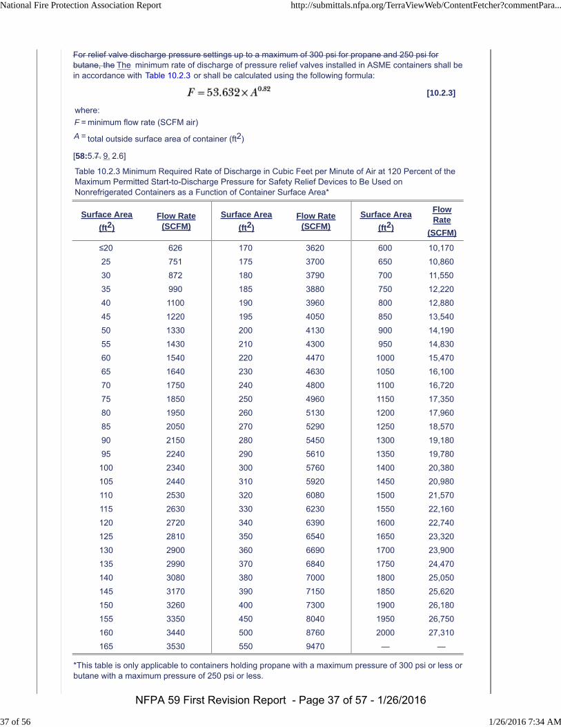
For relief valve discharge pressure settings up to a maximum of 300 psi for propane and 250 psi forbutane, the The minimum rate of discharge of pressure relief valves installed in ASME containers shall bein accordance with Table 10.2.3 or shall be calculated using the following formula:
[10.2.3]
where:
F = minimum flow rate (SCFM air)
A = total outside surface area of container (ft2)
[58:5.7. 9. 2.6]
Table 10.2.3 Minimum Required Rate of Discharge in Cubic Feet per Minute of Air at 120 Percent of theMaximum Permitted Start-to-Discharge Pressure for Safety Relief Devices to Be Used onNonrefrigerated Containers as a Function of Container Surface Area*
Surface Area
(ft2)
Flow Rate(SCFM)
Surface Area
(ft2)
Flow Rate(SCFM)
Surface Area
(ft2)
FlowRate
(SCFM)
≤20 626 170 3620 600 10,170
25 751 175 3700 650 10,860
30 872 180 3790 700 11,550
35 990 185 3880 750 12,220
40 1100 190 3960 800 12,880
45 1220 195 4050 850 13,540
50 1330 200 4130 900 14,190
55 1430 210 4300 950 14,830
60 1540 220 4470 1000 15,470
65 1640 230 4630 1050 16,100
70 1750 240 4800 1100 16,720
75 1850 250 4960 1150 17,350
80 1950 260 5130 1200 17,960
85 2050 270 5290 1250 18,570
90 2150 280 5450 1300 19,180
95 2240 290 5610 1350 19,780
100 2340 300 5760 1400 20,380
105 2440 310 5920 1450 20,980
110 2530 320 6080 1500 21,570
115 2630 330 6230 1550 22,160
120 2720 340 6390 1600 22,740
125 2810 350 6540 1650 23,320
130 2900 360 6690 1700 23,900
135 2990 370 6840 1750 24,470
140 3080 380 7000 1800 25,050
145 3170 390 7150 1850 25,620
150 3260 400 7300 1900 26,180
155 3350 450 8040 1950 26,750
160 3440 500 8760 2000 27,310
165 3530 550 9470 — —
*This table is only applicable to containers holding propane with a maximum pressure of 300 psi or less orbutane with a maximum pressure of 250 psi or less.
National Fire Protection Association Report http://submittals.nfpa.org/TerraViewWeb/ContentFetcher?commentPara...
37 of 56 1/26/2016 7:34 AM
NFPA 59 First Revision Report - Page 37 of 57 - 1/26/2016
For SI units;, : 1 SCFM = 0.0283 m3/min, 1 psi (gauge) = 6.9 kPa (gauge).
Note: Flow rate in SCFM air.
Submitter Information Verification
Submitter Full Name: Sonia Barbosa
Organization: [ Not Specified ]
Street Address:
City:
State:
Zip:
Submittal Date: Fri Jan 22 14:09:43 EST 2016
Committee Statement
Committee Statement: Updating extracted text.
Response Message:
National Fire Protection Association Report http://submittals.nfpa.org/TerraViewWeb/ContentFetcher?commentPara...
38 of 56 1/26/2016 7:34 AM
NFPA 59 First Revision Report - Page 38 of 57 - 1/26/2016
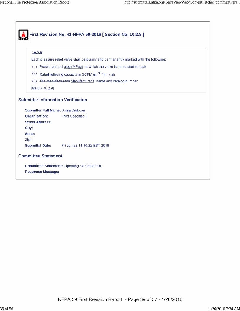
First Revision No. 41-NFPA 59-2016 [ Section No. 10.2.8 ]
10.2.8
Each pressure relief valve shall be plainly and permanently marked with the following:
(1) Pressure in psi psig (MPag) at which the valve is set to start-to-leak
(2) Rated relieving capacity in SCFM (m 3 /min) air
(3) The manufacturer's Manufacturer’s name and catalog number
[58:5.7. 9. 2.9]
Submitter Information Verification
Submitter Full Name: Sonia Barbosa
Organization: [ Not Specified ]
Street Address:
City:
State:
Zip:
Submittal Date: Fri Jan 22 14:10:22 EST 2016
Committee Statement
Committee Statement: Updating extracted text.
Response Message:
National Fire Protection Association Report http://submittals.nfpa.org/TerraViewWeb/ContentFetcher?commentPara...
39 of 56 1/26/2016 7:34 AM
NFPA 59 First Revision Report - Page 39 of 57 - 1/26/2016
First Revision No. 8-NFPA 59-2015 [ Section No. 11.2.1 ]
11.2.1
Operating procedures manuals shall include operator actions to be taken if flammable concentrations offlammable liquids or gases are detected in the facility using the following:
(1) Fixed detectors
(2) Portable detectors
Operating malfunctions
(3) Human senses
Submitter Information Verification
Submitter Full Name: Eric Nette
Organization: [ Not Specified ]
Street Address:
City:
State:
Zip:
Submittal Date: Wed Oct 28 12:49:22 EDT 2015
Committee Statement
CommitteeStatement:
Operating malfunctions are not an appropriate means for the detection of flammable liquids orgases. While leaks may be found after a malfunction, this reference is not appropriate for theintent of the statement.
ResponseMessage:
Public Input No. 40-NFPA 59-2015 [Section No. 11.2.1]
National Fire Protection Association Report http://submittals.nfpa.org/TerraViewWeb/ContentFetcher?commentPara...
40 of 56 1/26/2016 7:34 AM
NFPA 59 First Revision Report - Page 40 of 57 - 1/26/2016
First Revision No. 27-NFPA 59-2015 [ Sections 12.3.1, 12.3.2, 12.3.3, 12.3.4, 12.3.5 ]
4.8 Design and Installation.
4.8.1
All metallic components (containers, piping, valves, vaporizers, heat exchangers, etc.) containing LP-Gas(liquid or vapor state) that could have their integrity or reliability adversely affected by external, internal, oratmospheric corrosion during their intended service life shall be protected from corrosion.
4.8.2
The design and the installation procedure of external corrosion control cathodic protection systems shallbe documented.
4.8.3
Components whose integrity or reliability could be adversely affected by corrosion shall be:
(1) Protected from corrosion in accordance with 4.8 through 4.12 as applicable
(2) Inspected under a program of scheduled maintenance in accordance with 12.3.1 and 12.3.2
4.9 Atmospheric Corrosion Control.
4.9.1
Each exposed component that is subject to atmospheric corrosion shall be protected from atmosphericcorrosion by either of the following:
(1) A material that has been designed to resist the corrosive atmosphere involved; or
(2) Coating or jacketing suitable for the prevention of atmospheric corrosion
4.9.2
Where coatings are used, the component being coated shall be prepared to accept the coating and thecoating shall be applied as required by the coating manufacturer to ensure performance of the coating.
4.10* External Corrosion Control: Buried or Submerged Components.
4.10.1
Each buried or submerged component that is subject to external corrosion shall be protected fromexternal corrosion by:
(1) Material that has been designed to resist the corrosive environment involved; or
(2) Both of the following means:
(a)
(b)
4.10.1.1
* An external protective coating designed for operating conditions and for the environmentalconditions of the installation site, and installed to prevent corrosion of the protected component.
* A cathodic protection system (impressed current type or galvanic anode system) designed toprotect components in their entirety in accordance with the following:
i. The cathodic protection system shall be controlled so not to damage the component or itscoating
ii. Each component under cathodic protection shall be installed with test stations todetermine the adequacy of the cathodic protection
iii. Each test station shall have test leads installed that remain mechanically secure andelectrically conductive; are attached to a component to minimize stress conditions on thatcomponent; and are coated with electrically insulating material compatible with the coatingon the component.
National Fire Protection Association Report http://submittals.nfpa.org/TerraViewWeb/ContentFetcher?commentPara...
41 of 56 1/26/2016 7:34 AM
NFPA 59 First Revision Report - Page 41 of 57 - 1/26/2016
Prior to installation, each container, length of pipe, and other components shall be visually inspected at theinstallation site to identify damage.
4.10.1.1.1
Damage to the container, pipe, or component that could impair its serviceability shall be repaired aspermitted by pressure vessel, pipe, and component codes.
4.10.1.1.2
Any coating damage shall be repaired using materials compatible with the existing coating followingmanufacturer’s procedures.
4.10.1.2
Components shall be surrounded by earth or sand that is free of rocks and abrasives, and firmly tampedin place.
4.10.1.3
The portions of a partially underground, unmounded ASME container that are below the surface of theground and for a vertical distance of at least 3 in. (75 mm) above that surface shall comply with 4.8. Theremaining aboveground portion of the container shall be coated against atmospheric corrosion.
4.10.1.4
The part of an aboveground ASME container in contact with saddles or foundation shall be provided ameans to minimize corrosion.
4.10.2
Where cathodic protection is applied, components that are electrically interconnected shall be protectedas a unit.
4.10.3
The requirements of 4.10 shall be installed and placed in operation within 1 year after completion of initialsystem installation.
4.10.3.1
The requirements of 4.10 shall not apply where technical documentation that a corrosive environmentdoes not exist is approved by the AHJ. Such documentation shall be based on testing, investigation, orexperience in the area of application and shall include, as a minimum, soil resistivity measurements, andtests for corrosion accelerating bacteria.
4.10.3.2
Tests are required after 6 months of burial of the system identified in 4.10.1 including component-to-soilpotential measurements with respect to either a continuous reference cell electrode or an electrode usingclose spacing, not to exceed 20 ft (6 m), and soil resistivity measurements at potential profile peaklocations to evaluate the potential profile at the component or along the pipeline. If tests indicate that acorrosive condition exists, the affected components shall be cathodically protected in accordance withSection 12.3.
4.10.3.3
After the initial tests in 4.10.3.2, additional tests shall be conducted every 3 years and not exceeding 39months to reevaluate the condition of the unprotected components. If tests indicate that an activecorrosion exists either by electrical survey of leak repair or exposed pipe inspection records, the affectedcomponents shall be cathodically protected in accordance with 4.10.
4.10.4
Where insulating devices (flange, fitting, union) for cathodic protection are installed, precaution shall betaken to prevent arcing in areas where combustible atmospheres are anticipated.
4.10.5
Where components are located in close proximity to electric transmission tower footings, ground cables,or counterpoises, or in areas where fault currents or unusual risk of lightning is anticipated, they shall beprovided with protection against damage due to fault currents or lightning, and protective measures shallbe taken at insulating devices.
National Fire Protection Association Report http://submittals.nfpa.org/TerraViewWeb/ContentFetcher?commentPara...
42 of 56 1/26/2016 7:34 AM
NFPA 59 First Revision Report - Page 42 of 57 - 1/26/2016
4.11 Internal Corrosion Control.
Each component that is subject to internal corrosive attack shall be protected from internal corrosion byone of the following:
(1) Material that has been designed to resist the corrosive fluid involved; or
(2) Coating, inhibitor, or other means
4.12 Interference Currents.
4.12.1
Each component that is subject to electrical current interference shall be protected by a continuingprogram to minimize the detrimental effects of interference currents.
4.12.2
Each cathodic protection system shall be designed and installed so as to minimize any adverse effects itmight cause to adjacent metal components.
4.12.3
Each impressed current power source shall be installed to prevent adverse interference withcommunications and control systems.
Submitter Information Verification
Submitter Full Name: Eric Nette
Organization: [ Not Specified ]
Street Address:
City:
State:
Zip:
Submittal Date: Fri Oct 30 10:03:24 CDT 2015
Committee Statement
CommitteeStatement:
Sections 12.2 to 12.2.5.3 in chapter 12 specify requirements for installation of corrosionprotection and therefore should not be placed in the Maintenance chapter. These paragraphshave been moved to a new 4.9 in chapter 4.
ResponseMessage:
Public Input No. 6-NFPA 59-2015 [New Section after 4.8.2.3]
National Fire Protection Association Report http://submittals.nfpa.org/TerraViewWeb/ContentFetcher?commentPara...
43 of 56 1/26/2016 7:34 AM
NFPA 59 First Revision Report - Page 43 of 57 - 1/26/2016
First Revision No. 9-NFPA 59-2015 [ Section No. 12.3.6.1 ]
12.3.1.1
Cathodic protection of buried or submerged components shall comply with the following:
(1) Cathodic protection systems installed in accordance with 4.10 shall be monitored by testing and theresults documented and retained per 12.10.2(3).
(2)
(3) Each buried or submerged component under cathodic protection shall be tested by personnelqualified to perform corrosion control monitoring at least once each calendar year, with intervals notexceeding 15 months, to determine whether the cathodic protection is performing as designed.
(4) Each cathodic protection rectifier or other impressed current power source shall be inspected bypersonnel qualified to perform corrosion control monitoring at least six times each calendar year, withintervals not exceeding 21⁄2 months, to ensure that it is performing as designed.
(5) Each reverse current switch, each diode, and each interference bond whose failure would jeopardizecomponent protection shall be electrically checked for proper performance at least six times eachcalendar year, with intervals not exceeding 21⁄2 months, by personnel qualified to perform corrosioncontrol monitoring. Each other interference bond shall be checked at least once each calendar year,with intervals not exceeding 15 months.
(6) Whenever any portion of a buried pipe is exposed, the exposed portion of the pipe shall be examinedfor evidence of external corrosion in either of the following instances:
(a) If general external or localized external pitting corrosion is identified, additional examination inthe exposed area is necessary to identify the extent of the corrosion.
(b) If damage to the component coating is observed, the coating shall be repaired in accordancewith 4.10.1.1.2.
Submitter Information Verification
Submitter Full Name: Eric Nette
Organization: [ Not Specified ]
Street Address:
City:
State:
Zip:
Submittal Date: Wed Oct 28 12:52:35 EDT 2015
Committee Statement
Committee Statement: deleting repetitive wording.
Response Message:
* Cathodic protection system tests shall be described by one of the following:
(a) Producing a voltage of −0.85 volts or more negative, with reference to a saturated copper–copper sulfate half cell.
(b)
(c) Producing a voltage of −0.80 volts or more negative, with reference to a silver–silver chloridehalf cell.
* Producing a voltage of −0.78 volts or more negative, with reference to saturated KCl calomelhalf cell. Producing a voltage of −0.78 volts or more negative, with reference to saturated KClcalomel half cell.
National Fire Protection Association Report http://submittals.nfpa.org/TerraViewWeb/ContentFetcher?commentPara...
44 of 56 1/26/2016 7:34 AM
NFPA 59 First Revision Report - Page 44 of 57 - 1/26/2016
Public Input No. 41-NFPA 59-2015 [Section No. 12.3.6.1]
National Fire Protection Association Report http://submittals.nfpa.org/TerraViewWeb/ContentFetcher?commentPara...
45 of 56 1/26/2016 7:34 AM
NFPA 59 First Revision Report - Page 45 of 57 - 1/26/2016
First Revision No. 10-NFPA 59-2015 [ Section No. 12.6 ]
12.6 Maintenance of Fire Protection Equipment.
12.6.1
Maintenance of fire protection systems shall be in accordance with fire protection standards identified inChapter 13 .
12.6.2
Maintenance activities on fire control equipment protection systems shall be scheduled so that a minimumof equipment is taken out of service at any time and is returned to service as soon as maintenance iscomplete.
Submitter Information Verification
Submitter Full Name: Eric Nette
Organization: [ Not Specified ]
Street Address:
City:
State:
Zip:
Submittal Date: Wed Oct 28 12:58:05 EDT 2015
Committee Statement
CommitteeStatement:
New 12.6.1 clarifies that maintenance requirements for fire protection systems are located inchapter 13 and the standards identified in chapter 13.
ResponseMessage:
National Fire Protection Association Report http://submittals.nfpa.org/TerraViewWeb/ContentFetcher?commentPara...
46 of 56 1/26/2016 7:34 AM
NFPA 59 First Revision Report - Page 46 of 57 - 1/26/2016
First Revision No. 22-NFPA 59-2015 [ Section No. 13.2 ]
13.2 Gas, Fire, and Leak Detection.
13.2.1
Those areas, including enclosed buildings, that have a potential for flammable gas concentrations and fireshall be monitored as determined by the evaluation required in 13.1.1.
13.2.2
Continuously monitored flammable gas detection systems and low temperature sensors used for leakdetection purposes shall alarm at the plant site and at a constantly attended location if the plant site is notcontinuously manned.
13.2.3
Flammable gas detection systems shall alarm at not more than 25 percent of the lower flammable limit ofthe gas or vapor being monitored.
Detail FR-33
13.2.4*
Where utilized, leak detection shall be permitted to be used in addition to, but not in lieu of, gasdetection.
13.2.5*
Fire detectors shall alarm at the plant site and at a constantly attended location if the plant site is notcontinually manned.
13.2.6*
Where installed as determined by the evaluation required in 13.1.1, the following fire alarm componentsshall be designed, installed, documented, tested, and maintained in accordance with NFPA 72, NationalFire Alarm and Signaling Code :
(1) Initiating devices (detectors — smoke, flame, heat, etc.)
(2) Fire system monitor panels
(3) Notification appliances (strobes, sirens, etc.)
(4) Fire system activation devices on installed extinguishment/suppression systems (water deluge, fixeddry chemical systems)
(5) Field wiring between initiating, notification components, activation/suppression system, and controlpanels
(6) Power supply and backup power equipment for fire alarm system
Supplemental Information
File Name Description
FR-22_A.13.2.5.docx
Submitter Information Verification
Submitter Full Name: Eric Nette
Organization: [ Not Specified ]
Street Address:
City:
National Fire Protection Association Report http://submittals.nfpa.org/TerraViewWeb/ContentFetcher?commentPara...
47 of 56 1/26/2016 7:34 AM
NFPA 59 First Revision Report - Page 47 of 57 - 1/26/2016
5Ŝǘŀƛƭ FR-оо, New annex ƳŀǘŜNJƛŀƭ NJŜƭŀǘŜŘ ǘƻ Cwнн
A.13.2.5
Where fire protection systems are installed in accordance with NFPA 72 and are planned for
integration with other systems, NFPA 3 may be useful in the commissioning and testing of the
integrated systems.
NFPA 59 First Revision Report - Page 48 of 57 - 1/26/2016
State:
Zip:
Submittal Date: Thu Oct 29 17:05:44 CDT 2015
Committee Statement
CommitteeStatement:
The recognition of low temperature detection in 13.2 to compliment gas detection at facilitieshandling refrigerated LPG is appropriate and aligns with similar actions taken by the NFPA 59ATC.
The additional annex material identifying NFPA 3 provides additional guidance when integratingvarious fire protection and life systems with other systems.
ResponseMessage:
Public Input No. 45-NFPA 59-2015 [Section No. 13.2]
Public Input No. 56-NFPA 59-2015 [New Section after A.13.2.4]
National Fire Protection Association Report http://submittals.nfpa.org/TerraViewWeb/ContentFetcher?commentPara...
48 of 56 1/26/2016 7:34 AM
NFPA 59 First Revision Report - Page 49 of 57 - 1/26/2016
First Revision No. 31-NFPA 59-2015 [ Section No. 13.4.3 ]
13.6 Special Protection.
13.6.1*
If insulation is used, it shall comply with NFPA 290, Standard for Fire Testing of Passive ProtectionMaterials for Use on LP-Gas Containers .
13.6.2
If mounding or burial is used, the provisions of 5.5.2 shall constitute adequate protection.
13.6.3
If water spray fixed systems are used, they shall comply with NFPA 15, Standard for Water Spray FixedSystems for Fire Protection , and shall be automatically actuated by fire-responsive devices and alsoshall have a capability for manual actuation.
13.6.4
If monitor nozzles are used, they shall be located and arranged so that container surfaces likely to beexposed to fire will be wetted. Such systems shall otherwise comply with NFPA 15, Standard for WaterSpray Fixed Systems for Fire Protection , and shall be automatically actuated by fire-responsive devicesand also shall have a capability for manual actuation.
13.6.5*
If insulation is used, it shall be capable of limiting the container temperature to not over 800°F (427°C) fora minimum of 50 minutes, as determined by test with insulation applied to a steel plate and subjected to atest flame substantially over the area of the test plate, and it shall be resistant to weathering and theaction of hose streams.
Submitter Information Verification
Submitter Full Name: Eric Nette
Organization: [ Not Specified ]
Street Address:
City:
State:
Zip:
Submittal Date: Fri Oct 30 10:39:01 CDT 2015
Committee Statement
CommitteeStatement:
The special protection section is not specific to fire protection water systems and has beenrelocated to reflect this.
ResponseMessage:
National Fire Protection Association Report http://submittals.nfpa.org/TerraViewWeb/ContentFetcher?commentPara...
49 of 56 1/26/2016 7:34 AM
NFPA 59 First Revision Report - Page 50 of 57 - 1/26/2016
First Revision No. 20-NFPA 59-2015 [ Section No. 13.4.4 ]
13.4.3
Fire protection water systems, where used, shall be designed, installed, and maintained in accordancewith the following NFPA standards, as applicable, considering the fire control problems in facilities coveredby this standard:
(1) NFPA 13, Standard for the Installation of Sprinkler Systems
(2) NFPA 14, Standard for the Installation of Standpipe and Hose Systems
(3) NFPA 15, Standard for Water Spray Fixed Systems for Fire Protection
(4) NFPA 20, Standard for the Installation of Stationary Pumps for Fire Protection
(5) NFPA 22, Standard for Water Tanks for Private Fire Protection
(6) NFPA 24, Standard for the Installation of Private Fire Service Mains and Their Appurtenances
(7) NFPA 25 , Standard for the Inspection, Testing, and Maintenance of Water-Based Fire ProtectionSystems
(8) NFPA 1961, Standard on Fire Hose
(9) NFPA 1962, Standard for the Care, Use, Inspection, Service Testing, and Replacement of Fire Hose,Coupling, Nozzles, and Fire Hose Appliances.
(10) NFPA 1963, Standard for Fire Hose Connections
Submitter Information Verification
Submitter Full Name: Eric Nette
Organization: [ Not Specified ]
Street Address:
City:
State:
Zip:
Submittal Date: Thu Oct 29 16:33:08 CDT 2015
Committee Statement
CommitteeStatement:
The recognition of NFPA 25 identifies maintenance requirements for water based fire protections asthe maintenance requirements were removed from the specific water based system standards(NFPA 13, 14, 15, 20, 22, 24, etc) and relocated in NFPA 25 over 10 years ago. The recognition ofNFPA 25 in this standard is necessary and aligns with changes being made in the LNG standardNFPA 59A. NFPA 16 was moved to this section to properly categorize it as a water based systemstandard.
ResponseMessage:
Public Input No. 49-NFPA 59-2015 [Section No. 13.4.4]
National Fire Protection Association Report http://submittals.nfpa.org/TerraViewWeb/ContentFetcher?commentPara...
50 of 56 1/26/2016 7:34 AM
NFPA 59 First Revision Report - Page 51 of 57 - 1/26/2016
First Revision No. 21-NFPA 59-2015 [ Section No. 13.5.3 ]
13.5.3
Where fixed fire-extinguishing and other fire control systems are provided, such systems shall bedesigned, installed, and maintained in accordance with the following NFPA standards, as applicable:
(1) NFPA 10, Standard for Portable Fire Extinguishers
(2) NFPA 11, Standard for Low-, Medium-, and High-Expansion Foam
(3) NFPA 12, Standard on Carbon Dioxide Extinguishing Systems
(4) NFPA 12A, Standard on Halon 1301 Fire Extinguishing Systems
NFPA 16 , Standard for the Installation of Foam-Water Sprinkler and Foam-Water Spray Systems
(5) NFPA 17, Standard for Dry Chemical Extinguishing Systems
NFPA 25 , Standard for the Inspection, Testing, and Maintenance of Water-Based Fire ProtectionSystems
(6) NFPA 2001, Standard on Clean Agent Fire Extinguishing Systems
Submitter Information Verification
Submitter Full Name: Eric Nette
Organization: [ Not Specified ]
Street Address:
City:
State:
Zip:
Submittal Date: Thu Oct 29 16:36:27 CDT 2015
Committee Statement
Committee Statement: NFPA 16 and NFPA 25 are standards for water based fire protection systems.
Response Message:
Public Input No. 50-NFPA 59-2015 [Section No. 13.5.3]
National Fire Protection Association Report http://submittals.nfpa.org/TerraViewWeb/ContentFetcher?commentPara...
51 of 56 1/26/2016 7:34 AM
NFPA 59 First Revision Report - Page 52 of 57 - 1/26/2016
First Revision No. 12-NFPA 59-2015 [ Section No. 13.6 ]
13.7 Maintenance of Fire Protection Equipment.
Facility operators Operators shall prepare and implement a maintenance program for all plant fireprotection equipment.
Submitter Information Verification
Submitter Full Name: Eric Nette
Organization: [ Not Specified ]
Street Address:
City:
State:
Zip:
Submittal Date: Wed Oct 28 14:52:49 EDT 2015
Committee Statement
Committee Statement: Unnecessary modifier to the word Operator.
Response Message:
Public Input No. 51-NFPA 59-2015 [Section No. 13.6]
National Fire Protection Association Report http://submittals.nfpa.org/TerraViewWeb/ContentFetcher?commentPara...
52 of 56 1/26/2016 7:34 AM
NFPA 59 First Revision Report - Page 53 of 57 - 1/26/2016
First Revision No. 32-NFPA 59-2015 [ Section No. 13.8.1 ]
13.9.1
Each facility operator utility gas plant shall have a security system with controlled access, which shall bedesigned to minimize entry by unauthorized persons.
Submitter Information Verification
Submitter Full Name: Eric Nette
Organization: [ Not Specified ]
Street Address:
City:
State:
Zip:
Submittal Date: Fri Oct 30 10:41:39 CDT 2015
Committee Statement
CommitteeStatement:
Clarification since utility gas plant is defined and facility operator is not. The plant needs tohave a security system and not just the operator.
ResponseMessage:
National Fire Protection Association Report http://submittals.nfpa.org/TerraViewWeb/ContentFetcher?commentPara...
53 of 56 1/26/2016 7:34 AM
NFPA 59 First Revision Report - Page 54 of 57 - 1/26/2016
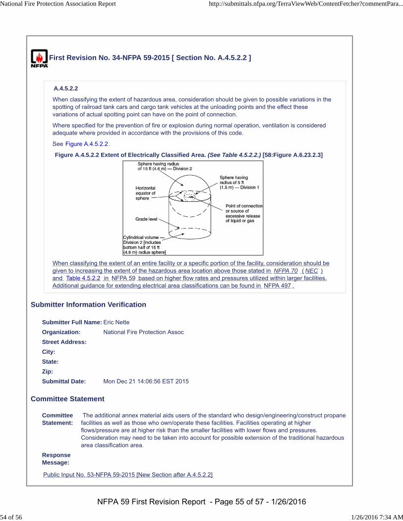
First Revision No. 34-NFPA 59-2015 [ Section No. A.4.5.2.2 ]
A.4.5.2.2
When classifying the extent of hazardous area, consideration should be given to possible variations in thespotting of railroad tank cars and cargo tank vehicles at the unloading points and the effect thesevariations of actual spotting point can have on the point of connection.
Where specified for the prevention of fire or explosion during normal operation, ventilation is consideredadequate where provided in accordance with the provisions of this code.
See Figure A.4.5.2.2.
Figure A.4.5.2.2 Extent of Electrically Classified Area. (See Table 4.5.2.2.) [58:Figure A.6.23.2.3]
When classifying the extent of an entire facility or a specific portion of the facility, consideration should begiven to increasing the extent of the hazardous area location above those stated in NFPA 70 ( NEC )and Table 4.5.2.2 in NFPA 59 based on higher flow rates and pressures utilized within larger facilities.Additional guidance for extending electrical area classifications can be found in NFPA 497 .
Submitter Information Verification
Submitter Full Name: Eric Nette
Organization: National Fire Protection Assoc
Street Address:
City:
State:
Zip:
Submittal Date: Mon Dec 21 14:06:56 EST 2015
Committee Statement
CommitteeStatement:
The additional annex material aids users of the standard who design/engineering/construct propanefacilities as well as those who own/operate these facilities. Facilities operating at higherflows/pressure are at higher risk than the smaller facilities with lower flows and pressures.Consideration may need to be taken into account for possible extension of the traditional hazardousarea classification area.
ResponseMessage:
Public Input No. 53-NFPA 59-2015 [New Section after A.4.5.2.2]
National Fire Protection Association Report http://submittals.nfpa.org/TerraViewWeb/ContentFetcher?commentPara...
54 of 56 1/26/2016 7:34 AM
NFPA 59 First Revision Report - Page 55 of 57 - 1/26/2016
First Revision No. 16-NFPA 59-2015 [ Sections A.10.1, A.11.2.3 ]
A.10.1
Based on information in ANSI/API 521, Guide for Pressure-Relieving and Depressuring Systems , safetyrelieve valves that are in liquid service when relieving do not entrain sufficient volumes of air to dilute themixture to below LEL levels. Additional factors should be considered when establishing the electrical areaclassification and classification distances near relief valves in liquid service.
Experience has indicated that for safety relief valves in vapor service only and those safety relief valvesthat emit a mist, a vertical and unimpeded vent of high-velocity hydrocarbon gases will entrain sufficient airwithin a very short distance so that the resultant plume will be diluted below the lower flammable limit.This behavior is documented in ANSI/API 521, Guide for Pressure-Relieving and Depressuring Systems .This document was based, in part, on an API-commissioned study by Battelle Memorial Institute, “TheEffect of Velocity, Temperature, and Gas Molecular Weight on Flammability Limits in Wind-Blown Jets ofHydrocarbon Gases.”
These reports clearly indicate that a vertical and unimpeded jet from a safety relief valve in vapor serviceonly and safety relief valves that emit a mist will be diluted below its lower flammable limit within 50 pipediameters of the issuing jet and that the effects of “wind-tilt” can be safely neglected if a 50 ft (15 m)horizontal clearance is provided between the jet and a source of ignition. A high velocity jet is defined as ajet having an exit velocity in excess of 100 ft/sec (30.5 m/sec), which is slightly more than an order ofmagnitude less than the acoustic velocity that can be anticipated at the throat of an operating relief valve.ANSI/API 521 also indicates that a partially open relief valve in vapor service will produce a velocitysufficient to achieve the necessary dilution.
Once such a mixture from a safety relief valve in vapor service only and those that emit a mist has beendiluted below its flammable limit, there are no known natural forces (including gravitational forces) that willcause the reconcentration of the LP-Gases so as to create a flammable cloud. The application of water, aseither a fog or a heavy stream, will not hasten and can actually inhibit the dilution of the jet stream. It isrecommended that this information be included in any emergency procedure manual and that theresponding emergency services be made aware of this information.
A.11.2.3
For information on purging and inerting equipment, see NFPA 326, Standard for the Safeguarding ofTanks and Containers for Entry, Cleaning, or Repair , and AGA Purging Principles and Practice.
Submitter Information Verification
Submitter Full Name: Eric Nette
Organization: [ Not Specified ]
Street Address:
City:
State:
Zip:
Submittal Date: Thu Oct 29 15:11:51 CDT 2015
Committee Statement
CommitteeStatement:
The rationale for not identifying an electrical area classification near safety relief valves has beenbased on the annex information in A.10.1 that states based on details in API 521 6.3.2.2, (2007edition w/May 2008 Addendum) that during the discharge from a safety relief valve that the dischargevelocity is such that sufficient volumes of air is entrained in the discharge stream and therefore dilutesthe mixture to below the LEL. While this is stated in API 521, it is only applicable to safety reliefvalves discharging vapor. API 521 6.3.2.3, and 6.3.2.4 additionally describes the discharges of mists
National Fire Protection Association Report http://submittals.nfpa.org/TerraViewWeb/ContentFetcher?commentPara...
55 of 56 1/26/2016 7:34 AM
NFPA 59 First Revision Report - Page 56 of 57 - 1/26/2016
and liquids and goes onto state that the same air entrainment activity is not expected to occur forliquid service valves and flammable concentrations in the area near the valves should be furtherevaluated. Safety relief valves in NFPA 59 facilities can be either in vapor or liquid service.
ResponseMessage:
Public Input No. 55-NFPA 59-2015 [Sections A.10.1, A.11.2.3]
National Fire Protection Association Report http://submittals.nfpa.org/TerraViewWeb/ContentFetcher?commentPara...
56 of 56 1/26/2016 7:34 AM
NFPA 59 First Revision Report - Page 57 of 57 - 1/26/2016