Embed Size (px)
Citation preview

© Festo Didactic 86354-00 37
When you have completed this exercise, you will be familiar with the effects of charge input, charge rate, and ambient temperature on the voltage and temperature profiles of a Ni-MI battery during a charge cycle. You will also be familiar with the effect of overcharge on the cycle life of a Ni-MI battery. You will know how to determine the charge efficiency of Ni-MI batteries. You will also know that proper charge control is required to achieve good charge efficiency and avoid battery overcharge.
The Discussion of this exercise covers the following points:
Charging fundamentals
Battery voltage and temperature profiles during charge
Risks related to overcharging a Ni-MI battery
Charge control and efficiency
Charging fundamentals
A secondary battery is charged by connecting a source of dc power to the battery. During the charge cycle, the dc power supplied by the source converts the active chemicals in the battery to their original state (i.e., the high-energy state the chemicals have when the battery is fully charged).
The number of charge-discharge cycles that can be performed during the life of a battery (i.e., the cycle life) not only depends on the discharge conditions (notably the depth of discharge), but also on the charge conditions (notably the charge-termination control which is discussed in the next exercise). The percentage of the battery’s nominal capacity that is being fed in during the charge is known as the charge input. For instance, terminating the charge of a Ni-MI battery at a charge input of 120% or less of the battery’s nominal capacity usually provides the longest cycle life for Ni-MI batteries (generally up to 1000 cycles), as shown in Figure 21. On the other hand, terminating the charge of a Ni-MI battery at a charge input of 150% offers a better relative battery capacity, but greatly reduces the cycle life of the battery (generally to 400-500 cycles).
Battery Charging Fundamentals
Exercise 3
EXERCISE OBJECTIVE
DISCUSSION OUTLINE
DISCUSSION

Exercise 3 – Battery Charging Fundamentals Discussion
38 © Fes t o Di dac t i c 86354- 00
Figure 21. Relative capacity of a Ni-MI battery versus the number of charge cycles for various charge inputs.
For the conversion of the active chemicals of a battery to their original high-energy state to be as effective as possible and cause no harm to the battery (thereby maximizing the battery life), the charge current and duration must be carefully controlled to avoid excessive battery voltage and temperature from developing during the charge. In particular, the extent of overcharge must be carefully limited, and high temperatures as well as excessive temperature fluctuations must be avoided. Ni-MI batteries are commonly charged by forcing a constant charge current into the battery. Various constant-current charge methods for Ni-MI batteries are discussed in the next exercise of this manual.
Battery voltage and temperature profiles during charge
Figure 22 shows the typical voltage and temperature profiles that are observed when a Ni-MI battery is charged with a constant current. In Figure 22a, there is a bump in the cell voltage profile when the charge input reaches about 120% of the battery’s nominal capacity. Figure 22b shows that the cell temperature starts to increase more rapidly when the battery capacity reaches about 60% of its nominal value.
Figure 22. Cell voltage and temperature of a Ni-MI battery versus charge input.
Number of cycles
Re
lative
ca
pa
city (
%)
150% charge input120% charge input
Charge input (% of nominal capacity) Charge input (% of nominal capacity)
°C °F
Ce
ll te
mp
era
ture
Ce
ll vo
lta
ge
(V
)
(a) Cell voltage profile (b) Cell temperature profile

Exercise 3 – Battery Charging Fundamentals Discussion
© Festo Didactic 86354-00 39
Figure 23 shows a family of voltage profiles of a Ni-MI battery measured at an ambient temperature of 20°C (68°F) for various charge rates. The higher the charge rate, the higher the voltage that develops across each battery cell. Also, the bump in the cell voltage profile of a Ni-MI battery at the end of the charge is sharper at higher charge rates.
Figure 23. Cell voltage profiles of a Ni-MI battery for various charge rates at an ambient temperature of 20°C (68°F).
Charge input (%)
Ce
ll vo
lta
ge
(V
)
0.1
0.3
1.0

Exercise 3 – Battery Charging Fundamentals Discussion
40 © Fes t o Di dac t i c 86354- 00
Figure 24 shows a family of temperature profiles of a Ni-MI battery for various charge rates. The higher the charge rate, the higher the rate of increase of the battery temperature near the end of the charge.
Figure 24. Temperature profiles of a Ni-MI battery for various charge rates.
Figure 25 shows a family of cell voltage profiles obtained when a Ni-MI battery is
charged with a constant current (0.3 ) for various ambient temperatures. The figure clearly shows that the bump in the cell voltage profile of a Ni-MI battery near the end of the charge becomes shallower as the ambient temperature increases.
Charge input (%)
Tem
pera
ture
°C °F
1
0.5
0.1

Exercise 3 – Battery Charging Fundamentals Discussion
© Festo Didactic 86354-00 41
Figure 25. Cell voltage profiles of a Ni-MI battery for various ambient temperatures at a
constant charge rate of 0.3 .
Risks related to overcharging a Ni-MI battery
Overcharging a Ni-MI battery can cause all kinds of damage to the battery cells and thus shortens the battery cycle life significantly. The most common harmful effects due to overcharge are pressure build-ups inside the battery cell. Pressure build-ups are due to excessive oxygen generation at the cathode and occur when the cathode reaches full charge. To alleviate this problem, Ni-MI batteries are set with an oxygen-recombination mechanism that prevents gassing (production of gas) up to a certain extent. This mechanism enables the excess oxygen produced by the cathode (when full charge is reached) to react with the hydrogen in the anode, producing water, and so limiting pressure build-ups. Nonetheless, proper charge control is required to avoid overcharging Ni-MI batteries, and thus, potential damages that could reduce the battery life. Note that the oxygen-recombination mechanism is possible because the metal hydride contained in the anode has a higher effective capacity than the materials contained in the cathode. This means that there is usually still enough material in the anode to recombine with the excess oxygen produced in the fully charged cathode. If the overcharge is prolonged for enough time, however, the materials in the anode will also reach full charge and gassing will occur.
Charge control and efficiency
When charging Ni-MI batteries using a constant current, proper charge control is required to ensure that the battery is fully charged when the charge is terminated,
Charge input (%)
Ce
ll vo
lta
ge
(V
)
45°C (113°F)
20°C (68°F)
0°C (32°F)

Exercise 3 – Battery Charging Fundamentals Discussion
42 © Fes t o Di dac t i c 86354- 00
and also to limit overcharge and prevent excessive battery temperatures. The voltage and temperature profiles obtained when Ni-MI batteries are charged using a constant current are used in battery chargers to implement efficient charge control. These charge-control techniques and charging methods are studied in the next exercise.
When charging a battery, the charge efficiency is the ratio of the energy that is actually used for the electrochemical conversion of the active materials to their original high-energy state to the total energy supplied to the battery being charged. The energy which is not used for the conversion of the active materials to the high-energy state is lost in producing unwanted reactions within the battery, such as surplus oxygen production (gassing).
Charging Ni-MI batteries is a process that has a relatively good charge efficiency, but is sensitive to both the ambient temperature and charge rate. Figure 26 shows the charge efficiency (measured in Figure 26 as the relative discharge capacity obtained after the charge cycle) of Ni-MI batteries as a function of ambient temperature for different charge rates. The charge efficiency of Ni-MI batteries provides a discharge capacity close to 100% at temperatures ranging from 0°C (32°F) to room temperature (about 20°C or 68°F), but the discharge capacity decreases significantly at temperatures above 25°C (77°F). Furthermore, the charge rate also influences charge efficiency, especially at higher temperatures. The higher the charge rate, the higher the charge efficiency.
Figure 26. Discharge capacity (measured at 0.2 discharge rate) of Ni-MI batteries versus ambient temperature during charge for various charge rates.
The charge-control technique also greatly influences charge efficiency as it determines the extent to which the battery is overcharged. In fact, at a certain point in the charge cycle, the energy supplied to the battery mainly produces heat and is no longer used to return the active chemicals in the battery to their high-energy state, thus reducing charge efficiency.
As charge efficiency takes
into account both the effi-
ciency of the charge cycle
and that of the discharge
cycle, it is in fact the
charge/discharge efficiency.
However, for brevity pur-
poses, the term charge
efficiency is generally used.
Temperature during charge (°C)
Dis
ch
arg
e c
ap
acity (
%)
Temperature during charge (°F)
0.1
0.3
1.0
Room temperature

Exercise 3 – Battery Charging Fundamentals Procedure Outline
© Festo Didactic 86354-00 43
The Procedure is divided into the following sections:
Set up and connections
Full battery discharge
Battery voltage and temperature profiles at a charge rate of 0.5 5
High voltages are present in this laboratory exercise. Do not make or modify any
banana jack connections with the power on unless otherwise specified.
Set up and connections
In this section, you will set up and connect the equipment.
a All exercises should ideally be performed at an ambient temperature between 20°C (68°F) and 25°C (77°F).
1. Refer to the Equipment Utilization Chart in Appendix A to obtain the list of equipment required to perform this exercise.
Install the equipment required in the Workstation.
2. Make sure the main power switch on the Four-Quadrant Dynamometer/ Power Supply is set to the O (off) position, then connect its Power Input to an ac power outlet.
3. Connect the USB port of the Four-Quadrant Dynamometer/ Power Supply to a USB port of the host computer.
4. Turn the Four-Quadrant Dynamometer/Power Supply on, then set the Operating Mode switch to Power Supply.
5. Turn the host computer on, then start the LVDAC-EMS software.
In the LVDAC-EMS Start-Up window, make sure the Four-Quadrant Dynamometer/Power Supply is detected. Select the network voltage and frequency that correspond to the voltage and frequency of the local ac power network, then click the OK button to close the LVDAC-EMS Start-Up window.
PROCEDURE OUTLINE
PROCEDURE
Exercise 3 – Battery Charging Fundamentals Procedure
44 © Fes t o Di dac t i c 86354- 00
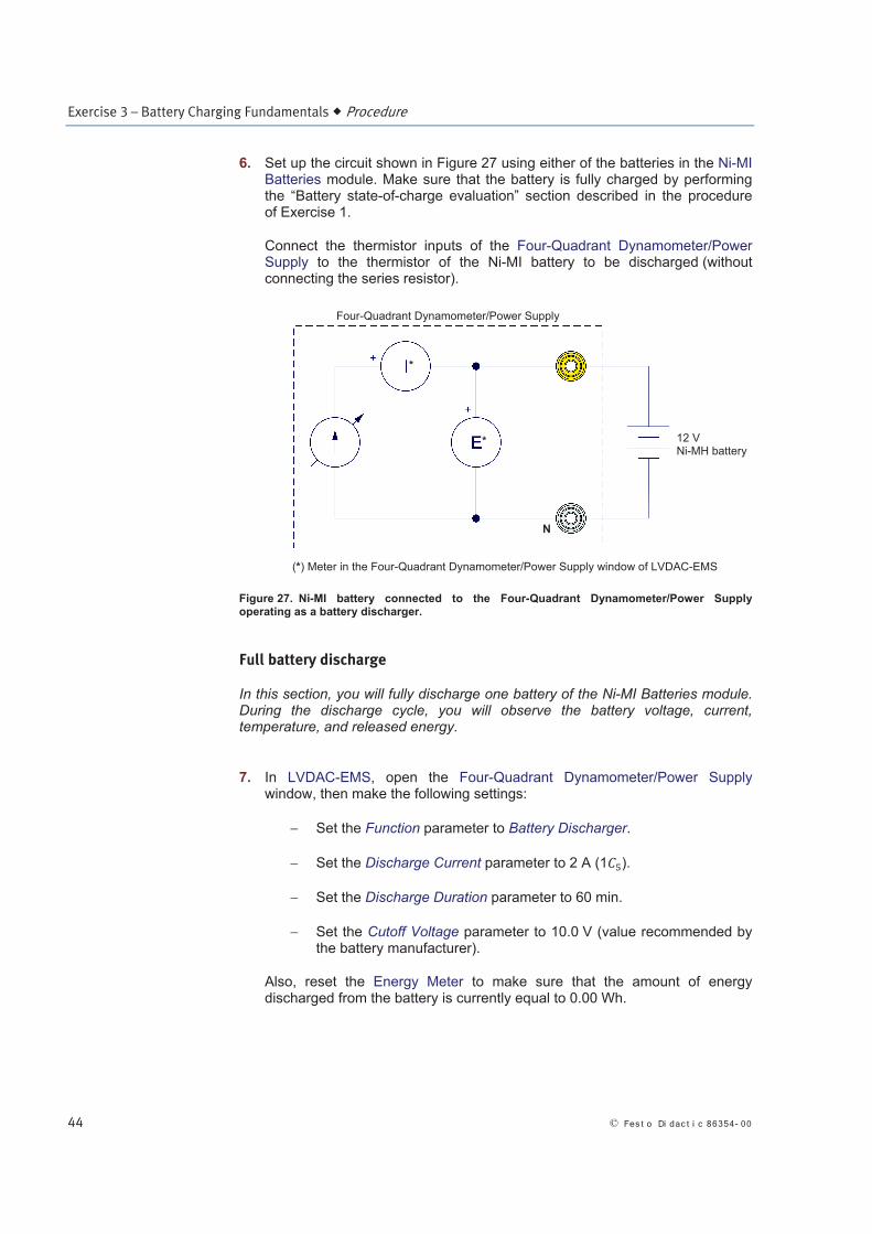
6. Set up the circuit shown in Figure 27 using either of the batteries in the Ni-MI Batteries module. Make sure that the battery is fully charged by performing the “Battery state-of-charge evaluation” section described in the procedure of Exercise 1.
Connect the thermistor inputs of the Four-Quadrant Dynamometer/Power Supply to the thermistor of the Ni-MI battery to be discharged (without connecting the series resistor).
Figure 27. Ni-MI battery connected to the Four-Quadrant Dynamometer/Power Supply operating as a battery discharger.
Full battery discharge
In this section, you will fully discharge one battery of the Ni-MI Batteries module. During the discharge cycle, you will observe the battery voltage, current, temperature, and released energy.
7. In LVDAC-EMS, open the Four-Quadrant Dynamometer/Power Supply window, then make the following settings:
Set the Function parameter to Battery Discharger.
Set the Discharge Current parameter to 2 A (1 ).
Set the Discharge Duration parameter to 60 min.
Set the Cutoff Voltage parameter to 10.0 V (value recommended by the battery manufacturer).
Also, reset the Energy Meter to make sure that the amount of energy discharged from the battery is currently equal to 0.00 Wh.
*
*
(*) Meter in the Four-Quadrant Dynamometer/Power Supply window of LVDAC-EMS
12 V Ni-MH battery
N
Four-Quadrant Dynamometer/Power Supply

Exercise 3 – Battery Charging Fundamentals Procedure
© Festo Didactic 86354-00 45
a The setting of the discharge duration corresponds to the time required to remove approximately 100% of the energy contained in a fully charged battery when discharging at a rate of 1 . Depending on the actual state of charge of the battery, the discharge will terminate when the cutoff voltage is reached or at the end of the discharge duration.
8. In LVDAC-EMS, open the Data Table window. Set the timer to make 480 records with an interval of 30 seconds between each record. This setting corresponds to a 240-minute period of observation, providing enough time to record the parameters during the battery discharge, the pause time required to cool the battery, and the subsequent battery charge.
Set the Data Table to record the voltage, current, energy, and temperature indicated by the meters in the Four-Quadrant Dynamometer/Power Supply window, and the time associated with each record.
9. In the Four-Quadrant Dynamometer/Power Supply window, start the Battery Discharger, then immediately start the timer in the Data Table window to begin recording data.
10. About 15 minutes after the battery discharge began, measure the battery voltage using an external multimeter. Compare the voltage measured with the multimeter with that indicated by the voltmeter on the Four-Quadrant Dynamometer/Power Supply. If the values differ, correct the cutoff voltage of the Battery Discharger accordingly. For example, if the module voltmeter underestimates the battery voltage by 0.3 V, reduce the cutoff voltage to 9.7 V to ensure the discharge terminates when the battery voltage is actually 10.0 V.
11. As soon as the Battery Discharger stops the charge (either because the discharge duration has elapsed or the cutoff voltage is reached), remove the Ni-MI Batteries module from the workstation (without removing the connections to the battery and thermistor) in order to ventilate the Ni-MH battery pack inside the module until its temperature decreases to less than 26°C (79°F). If available, use a fan to speed up the process. This step is necessary to return the battery temperature to near ambient temperature as soon as possible and proceed with the next section.
a Do not stop the timer in the Data Table window at the end of the discharge cycle.
12. While the Ni-MI Batteries module is being ventilated, record the amount of energy supplied by the battery (indicated by the Energy Meter in the Four-Quadrant Dynamometer/Power Supply window) during the discharge cycle.
Energy supplied during discharge: Wh

Exercise 3 – Battery Charging Fundamentals Procedure
46 © Fes t o Di dac t i c 86354- 00
13. Calculate the discharge capacity (in Ah) of the Ni-MI battery using the discharge duration measured during the discharge cycle.
Discharge duration: h
Discharge capacity: Ah
Battery voltage and temperature profiles at a charge rate of 0.5 5
In this section, you will charge the fully discharged Ni-MI battery at a rate of 0.5 (1 A) using the temperature cutoff (TCO) technique as a charge-control method. During the charge cycle, you will observe the battery voltage, current, and temperature, as well as the energy returned to the battery. You will then calculate the charge efficiency and plot the voltage and temperature profiles of the Ni-MI battery measured throughout the exercise. You will end the exercise by making some observations about the voltage and temperature profiles of the Ni-MI battery.
14. Before proceeding with the next step, wait for the battery temperature indicated by the Temperature Meter in LVDAC-EMS to drop below 26°C (79°F). When the temperature of the Ni-MI battery has decreased below 26°C (79°F), put the Ni-MI Batteries module back into the workstation and stop any external ventilation.
15. In the Four-Quadrant Dynamometer/Power Supply window, make the following settings:
Set the Function parameter to Ni-MI Battery Charger (Constant-Current Timed Charge with TCO). When the Ni-MI Battery Charger (Constant-Current Timed Charge with TCO) function is selected, the Four-Quadrant Dynamometer/Power Supply operates as a Ni-MI battery charger using the following parameters to achieve charge control: charge current, charge duration, and TCO.
Set the Charge Current parameter to 1 A (0.5 ). This sets the charge current of the Ni-MI battery charger to 1 A.
Set the Charge Duration parameter to 2.5 hours. This sets the duration of the charge cycle to 2.5 hours.
Set the TCO parameter to 50°C (122°F).
a Do not reset the Energy Meter.
Setting the TCO (temperature cutoff) to 50°C (122°F) makes the battery charger stop automatically when the battery reaches a temperature of 50°C (122°F). Other charge-control methods are discussed in detail in Exercise 4.
In this exercise, the TCO temperature should be reached before the end of the charge duration. However, in the event the TCO fails to work, a charge
From now on, the Ni-MI
Battery Charger (Constant-
Current Timed Charge with
TCO) function is referred to
as the Ni-MI Battery
Charger for brevity purpos-
es.

Exercise 3 – Battery Charging Fundamentals Procedure
© Festo Didactic 86354-00 47
duration of 2.5 hours has been set in order to prevent excessive battery overcharge.
16. In the Four-Quadrant Dynamometer/Power Supply window, start the Ni-MI Battery Charger.
Let the battery charge until the Ni-MI Battery Charger automatically stops the charge (when the measured battery temperature reaches the cutoff temperature of 50°C or 122°F). This should take approximately 120 minutes. When the charge is terminated, immediately stop the timer in the Data Table window to stop recording data, then save the recorded data.
17. Does the energy value displayed by the Energy Meter in the Four-Quadrant Dynamometer/Power Supply window show that the energy returned to the battery during the charge at 0.5 exceeds the energy supplied by the battery during the discharge?
Yes No
Record the amount of energy returned to the battery during the charge cycle.
Energy returned to the battery during charge: Wh
18. Calculate the charge efficiency (in %) of the charge cycle using the amount of energy supplied during the discharge recorded in step 12 and the amount of energy returned to the battery during the charge cycle recorded in the previous step.
Charge efficiency: %
19. Export your recorded data to a spreadsheet application and create separate plots for the voltage and temperature profiles of the Ni-MI battery during the
full discharge at a rate of 1 followed by a charge cycle at a rate of 0.5 using TCO as the charge termination method.
a It is suggested that you include the data table and the graph plotted in this exercise in your lab report.
20. Is there a “bump” in the voltage profile of the Ni-MI battery near the end of
the charge cycle at 0.5 ?
Yes No
21. Does the battery voltage decrease slightly at the end of the charge at 0.5 ?
Yes No

Exercise 3 – Battery Charging Fundamentals Conclusion
48 © Fes t o Di dac t i c 86354- 00
22. Is there a perceptible voltage plateau near the end of the charge cycle
at 0.5 ?
Yes No
23. Record the duration of the charge cycle at 0.5 , then calculate the charge input (percentage of the battery nominal capacity) that has been returned to the battery during the charge cycle.
Charge duration: h
Charge input: %
24. Repeat the previous step assuming that the charge stopped at the peak of the voltage bump (i.e., at the beginning of the voltage plateau) observed in the voltage profile of the Ni-MI battery during the charge cycle at 0.5 .
Charge duration at the peak of the voltage bump: h
Charge input at the peak of the voltage bump: %
25. Describe the temperature profile of the Ni-MI battery during the charge cycle at 0.5 .
26. Close LVDAC-EMS, then turn off all the equipment. Disconnect all leads and return them to their storage location.
In this exercise, you became familiar with the effects of charge input, charge rate, and ambient temperature on the voltage and temperature profiles of a Ni-MI battery during a charge cycle. You also became familiar with the effect of overcharge on the cycle life of a Ni-MI battery. You learned how to determine the charge efficiency of Ni-MI batteries. You also learned that proper charge control is required to achieve good charge efficiency and avoid battery overcharge.
1. What is the optimal charge input for a Ni-MI battery during a full charge cycle and why?
CONCLUSION
REVIEW QUESTIONS

Exercise 3 – Battery Charging Fundamentals Review Questions
© Festo Didactic 86354-00 49
2. What is the relationship between the voltage measured across a Ni-MI battery and the charge rate during a charge cycle? How is the bump observed in the voltage profile curve at the end of the charge cycle influenced by the charge rate?
3. What is the effect of the charge rate on the temperature of a Ni-MI battery during a charge cycle at a constant current rate?
4. Why is it necessary to avoid excessive overcharging of a Ni-MI battery?
5. During a full charge cycle, a Ni-MI battery is supplied a charge input equal to 120% of its nominal capacity. During the subsequent discharge cycle, the battery yields a total current equal to only 105% of its nominal capacity. Explain this phenomenon in relation to charge efficiency.