Embed Size (px)
Citation preview

NIF Laser Capabilities
C. Haynam, JM Di Nicola, P. Wegner, M. Bowers, D. Browning, S. Burkhart, S. Cohen, A. Deland, P. Di Nicola, S. Dixit, G. Erbert,
M. Henesian, M. Hermann, R. House, K. Jancaitis, K. LaFortune, R. Lowe-Webb, K. McCandless, V. Miller Kamm, M. Nostrand, C. Orth, B. Raymond, R. Sacks, M. Shaw, B. Van Wonterghem, P. Whitman, C. Widmayer, K. Wilhelmsen, L. Wong.
7000 East Avenue, Livermore, CA 94550, USA
[email protected] This work performed under the auspices of the U.S. Department of Energy by Lawrence Livermore National Laboratory under Contract DE-AC52-07NA27344.
Presented to NIF Users Group February 14, 2012

Haynam - NIF Users Group, Feb. 14, 2012 2 NIF-0711-22457.ppt
1.6 MJ, 435TW September 15, 2011

The NIF laser system is flexible and has supported a wide variety of shot campaigns
3 NIF-0711-22457.ppt
NEL and PDS 3ω Experiments Mar 2003 to Sep 2007
Peak
Pow
er (T
W/b
eam
)
Full NIF Equivalent 192 beam Energy (MJ)
NIF 3ω Experiments June 2009 to Aug 2011
2ns Flat in time
192 beam Energy (MJ) 1 2
11ns to 17ns Ignition Shape
1 2
4
3
2
1
0 0 2 4 6 8 10 12 14
Energy (kJ/beam)
Peak
Pow
er (T
W/b
eam
)
1
2
3
4
0 0
1
2
3
4
0 2 4 6 8 10 12
Peak Pow
er (T
W/beam)
Energy (kJ/beam)
Laser
HED
Laser & Target Diagnostics Calibration/Test Ignition & HED Experiments
Energy (kJ/beam)
Haynam - NIF Users Group, Feb. 14, 2012

The NIF laser has increased the energy and power on target since its initial commissioning
3ω P
ower
(TW
)
0.5
1.0
1.5
3ω E
nerg
y (M
J)
0.0
FM&
R
FM&
R
Igni
tion
Prep
arat
ion
Perio
d
Ice
Laye
r Com
mis
sion
ing
0
100
200
300
400
500
Time history of 3ω target shots from 2009 to present
NIF-0711-22457.ppt 4 Haynam - NIF Users Group, Feb. 14, 2012

The NIF laser has increased the energy and power on target since its initial commissioning
NIF 3ω target shots/month and energy from August 2010 to present
NIF-0711-22457.ppt 5 Haynam - NIF Users Group, Feb. 14, 2012
0
5
10
15
20
25
30
35
40
Num
ber o
f Sho
ts (binn
ed b
y en
ergy)
>=1.5MJ~1.4MJ~1.3MJ~1.0MJ300-‐900KJLow Energy

The NIF laser has demonstrated its 1.8 MJ design fluence on 192 beams
12/08
3/09
12/09 6/11
10/08
NIF Operating Conditions
• The NIF 3ω energy specification of 1.8 MJ requires an order of magnitude increase in operating fluence (energy/area) beyond that of previous ICF lasers
• The energy specification and design fluence were defined for a 20.5 ns ignition pulse with damage-equivalent Gaussian pulse duration of 3 ns1
• In June 2011 NIF operated all 192 beams at its 3ω design fluence2
─ 7.2 J/cm2 in a 21 ns ignition pulse with damage-equivalent Gaussian pulse duration of 2.1 to 2.3 ns
─ 8.3 J/cm2 scaled to 3 ns Mean 3ω fluence, J/cm2 3 ns
Tota
l Bea
m a
rea,
105
cm
2
1. NIF Laser System Performance Ratings, Proc. SPIE 3492, 1998. 2. Shots N110620-002 & N110630-001
NIF-0711-22457.ppt 6 Haynam - NIF Users Group, Feb. 14, 2012
We met the NIF design 3ω fluence requirements and will keep on increasing the 3ω energy to support experimental goals. Selected beamlines have also been
operated at an energy of 1.8MJ Full NIF Equivalent (FNE = single beamline * 192)

NIF has shown excellent ability to obtain the desired pulse shape and energy
Haynam - NIF Users Group, Feb. 14, 2012 7 NIF-0711-22457.ppt NIF-0711-22457.ppt

NIF has shown excellent shot to shot reproducibility
Haynam - NIF Users Group, Feb. 14, 2012 8
NIF delivered the requested pulse shape and energy
8 shots over a period of 2 months demonstrated high reproducibility
0"
10"
20"
30"
40"
0 2 4 6 8 10
Pow
er (T
W)
Time (ns)
Requested Measured (8 shots)
First laser-heated cryogenic hohlraums that perform like warm hohlraums
500
300
Time (ns) 0 4
0 0 TR
AD
(eV)
200
100
Laser Power
Lase
r Pow
er (T
W)
TRAD
Warm Hohlraum Cryo Hohlraum 21K
2
NIF-0711-22457.ppt
Excellent reproducibility of power and TRAD have been demonstrated

Laser performance is critical for tuning campaigns designed to reach ignition
Haynam - NIF Users Group, Feb. 14, 2012 9 NIF-0711-22457.ppt
Today’s talk will focus on the NIF’s demonstration of these laser capabilities. We plan to continuously improve the NIF laser to increase performance, reliability, and shot rate.
±150 ps
±10% ±10% ±10% ±12%
Peak ±15%
9.4Å
±10%
Foot ±30%
(9 laser parameters) (2 laser parameters)
(3 laser parameters)

Adjusting laser parameters to optimize adiabat
• Adiabat optimization requires adjustment of:
— Power — Timing
Haynam - NIF Users Group, Feb. 14, 2012 10
First will discuss laser parameters required for Adiabat Optimization
Wavelength separation
NIF-0711-22457.ppt
(9 laser parameters)

The NIF Master Oscillator Room has supported 2107 System Shots to date
Haynam - NIF Users Group, Feb. 14, 2012 11 NIF-0711-22457.ppt

We demonstrated the type of precision adjustments to the pulse shape required for shock timing
Haynam - NIF Users Group, Feb. 14, 2012 12 NIF-0711-22457.ppt
Shape-shifted request Shape-shifted avg meas Non-shifted request Non-shifted avg meas
Shape-shifting (12 shots shifted, 16 shots un-shifted)
10±2% increase in amplitude 100±10 ps
time delay
Pow
er (T
W/b
eam
)
0.8 0.7 0.6 0.5 0.4 0.3 0.2 0.1
0. 6 7 8 9 10 11 12 Time (ns)

Two-color tuning allowed us to adjust a “pancake” implosion to round without changing laser cone fraction
Haynam - NIF Users Group, Feb. 14, 2012 13 NIF-0711-22457.ppt
NIF routinely uses three separate colors for the 23.5° (λ1a), 30° (λ1b), and combined 44.5° & 50° (λ2) cones

Adjusting laser parameters to optimize velocity
• Velocity Optimization requires adjustment of:
— Peak Power — Focal spot
smoothing (measured in the Precision Diagnostics System – PDS)
Haynam - NIF Users Group, Feb. 14, 2012 14
Next discuss laser parameters required for Velocity Optimization
Wavelength separation
NIF-0711-22457.ppt
(2 laser parameters)
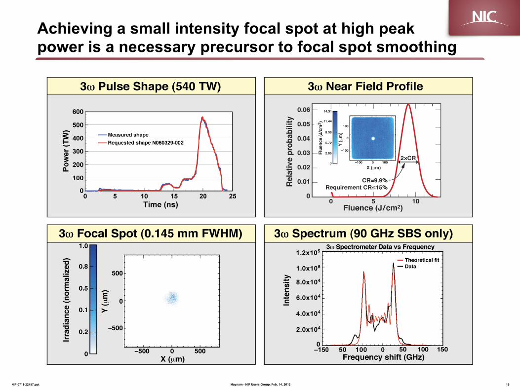
Achieving a small intensity focal spot at high peak power is a necessary precursor to focal spot smoothing
Haynam - NIF Users Group, Feb. 14, 2012 15 NIF-0711-22457.ppt

The inherent NIF spot size is very weakly dependent on peak power
Haynam - NIF Users Group, Feb. 14, 2012 16 NIF-0711-22457.ppt
• Beam profile at the target is stable on NIF because non-linear propagation effects are held in control all along the beamlines − ∆B held to <1.8 radians − High optical quality of all transmissive and reflective optics − Cone pinholes − Low air turbulance in enclosed beamlines

Beam smoothing is used on NIF
Haynam - NIF Users Group, Feb. 14, 2012 17 NIF-0711-22457.ppt

A continuous phase plate (CPP) is a continuous aggregation of small lenses
Haynam - NIF Users Group, Feb. 14, 2012 18 NIF-0711-22457.ppt

Beam conditioning is used to improve the focal spatial uniformity of the laser focal point
Haynam - NIF Users Group, Feb. 14, 2012 19 NIF-0711-22457.ppt

PDS measurement at 1.8MJ of simultaneously meeting point design beam conditioning, energy, temporal profile, and peak power requirements
Haynam - NIF Users Group, Feb. 14, 2012 20 NIF-0711-22457.ppt

One quad of the laser was used to demonstrate the full NIF energy at 3ω delivered to the designer-specified focal spot with all smoothing methods used simultaneously
Haynam - NIF Users Group, Feb. 14, 2012 21 NIF-0711-22457.ppt
• Energy and power on Q34B are multiplied by 48 quads to obtain FNE
1.89 MJ FNE 3ω energy N090108-002-999
0
1 0 0
2 0 0
3 0 0
4 0 0
5 0 0
6 0 0
0 2 4 6 8 1 0 1 2 1 4 1 6
T i m e ( n s )
3 ω
Pow
er (T
W F
NE
)
SXI image of 4 beams Shot N090109-003-999
Distance (mm)
Dis
tanc
e (m
m)
0 1 –1
0 1
–1

(3 laser parameters)
Adjusting laser parameters to optimize shape
Haynam - NIF Users Group, Feb. 14, 2012 22
Next will discuss laser parameters required for Shape Optimization
• Pointing accuracy
• Shape Optimization requires adjustment of Relative Power at the foot and peak of the laser pulse
— Synchronization — Power Balance
• Wavelength separation
Wavelength separation
NIF-0711-22457.ppt
Pointing
Relative power at foot &peak

Pointing stability was measured on 96 beams (plus 8 fiducial beams) delivered to a flat target with two SXIs"
Haynam - NIF Users Group, Feb. 14, 2012 23 NIF-0711-22457.ppt
49±4µm rms pointing error
Distance (µm)
Dis
tanc
e (µ
m)
700 microns between focal spots on new TAS camera Shot N100622-001-999
80 µm circle (Point Design)
SXI upper SXI lower
• 8 beam (single bundle) pointing shot completed 12/08 • Two 96 beam pointing shot series were performed
— 1st demonstrated beam to target pointing was 64µm rms (1/09) — 2nd demonstrated beam to target pointing was 49±4µm rms (6/10)
— Result includes post-shot TAS calibration correction for lower beams
Centroids LB1 (blue) LB2 (red)
Fiducials indicate target location Fiducials indicate target location

Pulse synchronization at Target Chamber Center (TCC) is well within 30 ps RMS requirement
Haynam - NIF Users Group, Feb. 14, 2012 24 NIF-0711-22457.ppt
0
20
40
60
80
100
-‐30 -‐20 -‐10 0 10 20 30
Num
ber o
f beams
Arrival time offset from TCC "T0" (ps)
~7 ps rms relative to fiducial MOR pulse shaping adds an
additional 18 ps rms
Rough synchronization verified in 2009 with the
SXD-B streak camera
New diode-base pulse synchronization diagnostic
commissioned in 2010
Resides at TCC and measures 192 beams in a few hours with
<8 ps resolution 37 ps rms
Improved synchronization measured in May 2011
Rod shot data after adjustments based on pulse synch diagnostic

We routinely meet the Ignition Point Design power balance and accuracy specifications
Haynam - NIF Users Group, Feb. 14, 2012 25 NIF-0711-22457.ppt
0
50
100
150
200
250
300
350
400
450
500
0%
5%
10%
15%
20%
25%
30%
0 5 10 15 20
Measured Po
wer (TW)
RMS Po
wer Balan
ce
Time (ns)
N110804-‐003-‐999
Rev5.1 Draft RequirementInners measured PBOuters measured PBMeasured PowerRequested power
Absolute Power Accuracy Power Balance

Summary
• NIF is a flexible laser platform — NIF has a wide range of shaped and Flat-in-time pulses
– Duration = 0.5ns to 30ns – Demonstrated energy and power = 1.6MJ, 435TW (192 beams) – Routine Quad pulse delays = 30ns – laser pulse width1
— NIF routinely generates short impulses on all quads – Duration = 88ps gaussian (FWHM) – 50J and 0.54TW per beamline – Routine Quad pulse delays = 20ns
— Inner and outer cone wavelength separation of up to 9.4A — Focal spot size is adjustable using continuous phase plates
• NIF is a precise laser platform — Demonstrated pointing of <50µm RMS — Demonstrated timing at TCC of < 20ps RMS — Demonstrated power balance meeting ignition specifications
• NIF shots are reproducible in energy and power
Haynam - NIF Users Group, Feb. 14, 2012 26 NIF-0711-22457.ppt
1Laser pulse width includes postpulse, if a postpulse is required to saturated regenerative amplifier

27


Example of laser damage scaling with pulse shape
NIF-0711-22457.ppt 29 Haynam - NIF Users Group, Feb. 14, 2012

LLNL-PRES-466711 30 Haynam - NIF Users Group, Feb. 14, 2012
AM compensator need and design (2/2)
Example of AM compensator for 2.2 nm-1 slope
• 1.5 m of HB PM fiber, • Dispersion between the two axis of the PM fiber D=1.67 ps/m leading to a free-spectral range of 1.5nm,
• Filter is tuned with temperature, • Temperature stability is <0.004 °C, • Compensation transfer function is given by:
Fibered AM compensator layout
Before / After compensation for 2.2 nm-1 slope. Miró simulation for 30 GHz of SBS.
Before compensation 12.2% of AM
(consistent with experimental data)
After compensation 0.3% of AM
0
0.5
1
1.5
2
2.5
3
3.5
4
0
0.2
0.4
0.6
0.8
1
1.2
1052 1052.2 1052.4 1052.6 1052.8 1053 1053.2 1053.4 1053.6 1053.8 1054
Spectral amplitu
deCo
mpe
nsation residu
e
Spectral amplitu
de
Wavelength (nm)
H(λ) AM compensatorL(λ) laser
spectral skew
H(λ)xL(λ) compensation
residue
Operating wavelength

The NIF laser system is flexible and has supported a wide variety of shot campaigns
Haynam - NIF Users Group, Feb. 14, 2012 31 NIF-0711-22457.ppt
NEL and PDS 3ω Experiments Mar 2003 to Sep 2007
Peak
Pow
er (T
W/b
eam
)
Full NIF Equivalent 192 beam Energy (MJ)
NIF 3ω Experiments June 2009 to Aug 2011
2ns Flat in time
192 beam Energy (MJ) 1 2
11ns to 17ns Ignition Shape
1 2
4
3
2
1
0 0 2 4 6 8 10 12 14
Energy (kJ/beam)
Peak
Pow
er (T
W/b
eam
)
1
2
3
4
0 0
1
2
3
4
0 2 4 6 8 10 12
Peak Pow
er (T
W/beam)
Energy (kJ/beam)
Laser
HED
Laser & Target Diagnostics Calibration/Test Ignition & HED Experiments
Energy (kJ/beam)
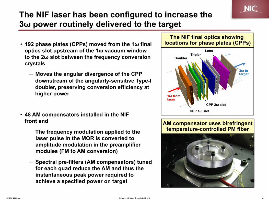
The NIF laser has been configured to increase the 3ω power routinely delivered to the target
Haynam - NIF Users Group, Feb. 14, 2012 32 NIF-0711-22457.ppt
• 192 phase plates (CPPs) moved from the 1ω final optics slot upstream of the 1ω vacuum window to the 2ω slot between the frequency conversion crystals
─ Moves the angular divergence of the CPP downstream of the angularly-sensitive Type-I doubler, preserving conversion efficiency at higher power
• 48 AM compensators installed in the NIF front end
─ The frequency modulation applied to the laser pulse in the MOR is converted to amplitude modulation in the preamplifier modules (FM to AM conversion)
─ Spectral pre-filters (AM compensators) tuned for each quad reduce the AM and thus the instantaneous peak power required to achieve a specified power on target
Doubler Tripler
CPP 1ω slot
CPP 2ω slot
Lens
1ω from laser
3ω to target
The NIF final optics showing locations for phase plates (CPPs)
AM compensator uses birefringent temperature-controlled PM fiber

New quad-specific AM compensators reduce AM levels to facilitate high power operation
Haynam - NIF Users Group, Feb. 14, 2012 33
NIF-0711-22457.ppt
AM measurements obtained without SSD δm(3GHz)= 5.0, δm(17GHz)= 0
0
2
4
6
8
10
0 2 4 6 8 10 12 14 16 18 20
Num
ber o
f qua
ds
AM (%) at at preamplifier output
Histogram of AM N091204-‐001-‐999 1.05MJ 285TW
Average AM=6.8% Max=18.1%
Min=2.1%
N091204-001-999
2 compensators
0
2
4
6
8
10
0 2 4 6 8 10 12 14 16 18 20
Num
ber o
f qua
ds
AM (%) at preamplifier output
Histogram of AM N110801-‐002-‐008 and N110809-‐001-‐013
48 compensators Average AM=1.8% Max=5.0%
Min=0%
N110801-002-008 N110809-001-013
Addition of 45 GHz SSD increases AM by ~3.4x
Simulations show that AM levels need to be held below 10 to 15%
The plan is to fully commission this capability over the next 3 to 6 months
400
450
500
550
600
0.0 0.1 0.2 0.3
3w Pow
er at T
CC (T
W)
Peak to Mean AM
12/0912/1014/10
Doubler/ tripler thickness (mm):
CPP in 2ω slot 90% 3ω transmission, including disposable debris shield
Peak to Mean AM (%)
0 10 20 30
Current operation
![Haynam v. Ohio State Bd. of Edn. · 2011-12-16 · [Cite as Haynam v.Ohio State Bd. of Edn., 2011-Ohio-6499.] IN THE COURT OF APPEALS OF OHIO SIXTH APPELLATE DISTRICT LUCAS COUNTY](https://img.pdfslide.net/doc/110x75/5f0abdc67e708231d42d1d58/haynam-v-ohio-state-bd-of-edn-2011-12-16-cite-as-haynam-vohio-state-bd-of.jpg)