Embed Size (px)
Citation preview

Niket Sheth
Chris Karman
Erik Scherbenske
Peter van der Hoop
BoneCrusher AutomationFloor Art Super Transcriber (F.A.S.T)
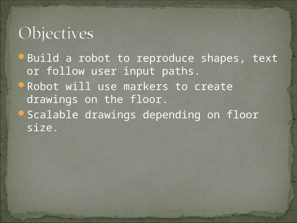
Build a robot to reproduce shapes, text or follow user input paths.
Robot will use markers to create drawings on the floor.
Scalable drawings depending on floor size.

Tethered Control using: JoystickKeyboardPre-Encoded InstructionsTouchpad
Wireless control should eventually replace tethered line
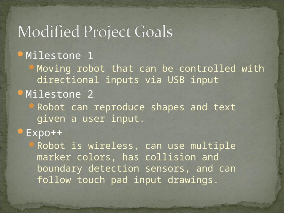
Milestone 1 Moving robot that can be controlled with
directional inputs via USB inputMilestone 2
Robot can reproduce shapes and text given a user input.
Expo++Robot is wireless, can use multiple marker
colors, has collision and boundary detection sensors, and can follow touch pad input drawings.

Input CPU
(MSP430)
Motor Drivers(L297, L298A)
Sensors
Marker


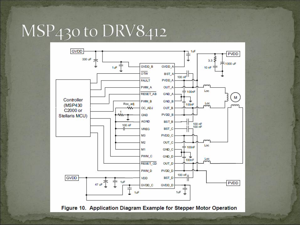
Robot moves with two Sure Step stepper motors that take inputs from DRV8412 motor drivers
The DRV8412 is a high performance integrated dual full bridge motor driverTakes 4 out-of-phase inputs to drive the motors
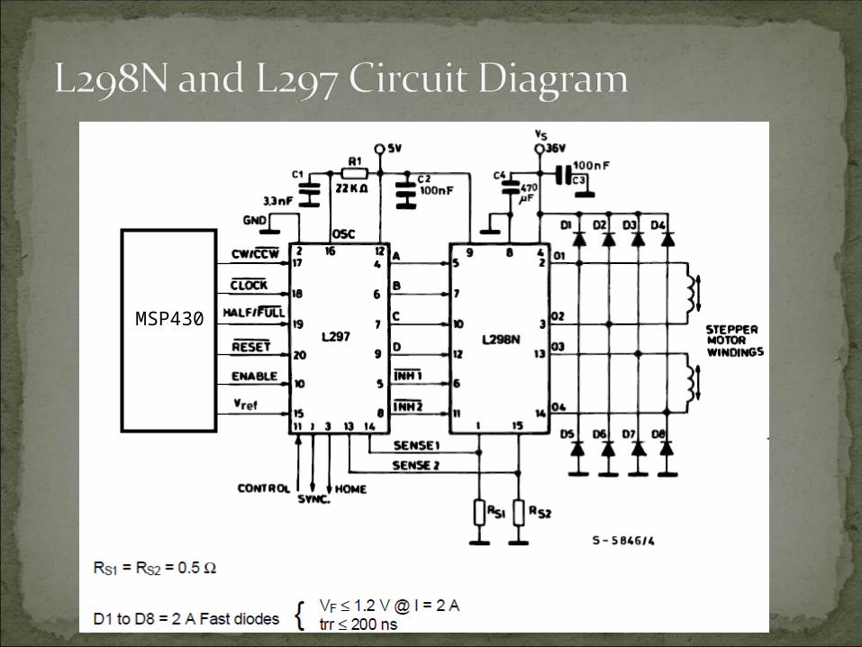
We have switched from the DRV8412 to the L298N and L297L297 generates 4 outputs from a single clock
input to drive the motors (connected to L298N)

Operating Supply Voltage up to 50V3A max current output Operating frequency up to 500kHzIntegrated self-protection circuits (under
voltage, over temperature, overload, short circuit)
No external schottky diodes requiredTakes four off-phase step functions as input
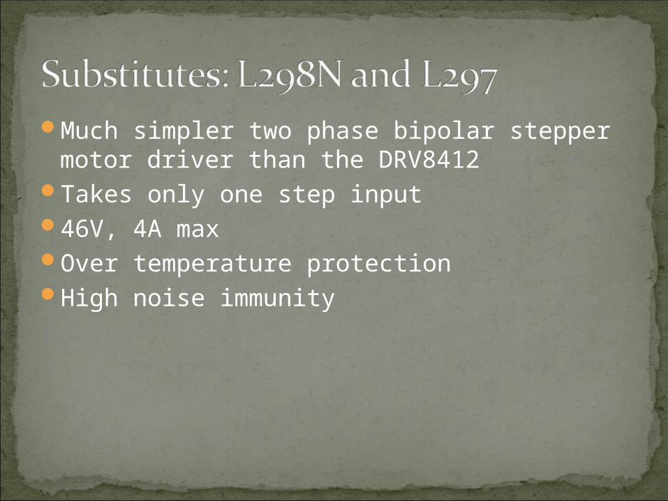
Much simpler two phase bipolar stepper motor driver than the DRV8412
Takes only one step input46V, 4A maxOver temperature protectionHigh noise immunity
MSP430
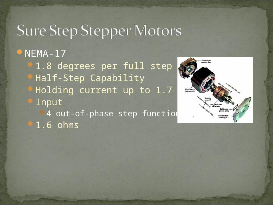
NEMA-171.8 degrees per full stepHalf-Step CapabilityHolding current up to 1.7 AInput
4 out-of-phase step functions1.6 ohms
Use a stepper motor to rotate markers into place (PWM).
MSP430 provides the path to drawMultiple color control through the motor
PWM.

Controls rotation of marker wheelSpring controlled pressure on markersColor change capabilitiesUses the same motor drivers and stepper
motors as the wheels
Rotate Pen Down/Up Motor
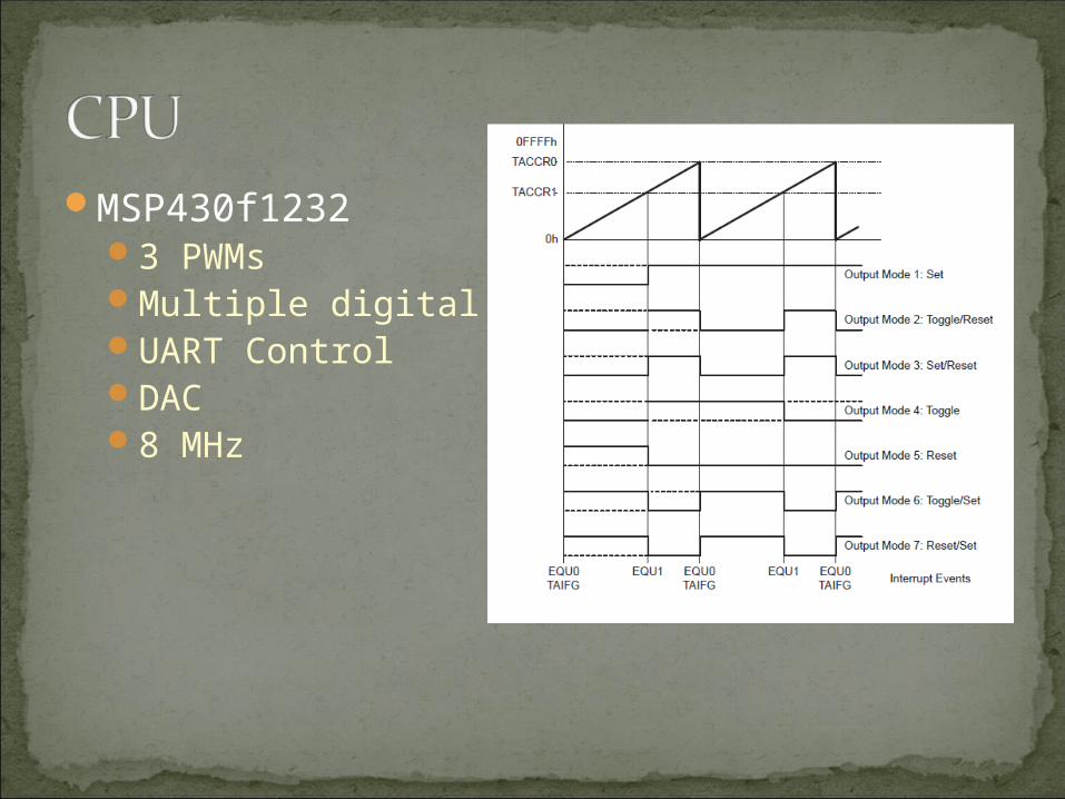
MSP430f12323 PWMsMultiple digital I/OUART ControlDAC8 MHz
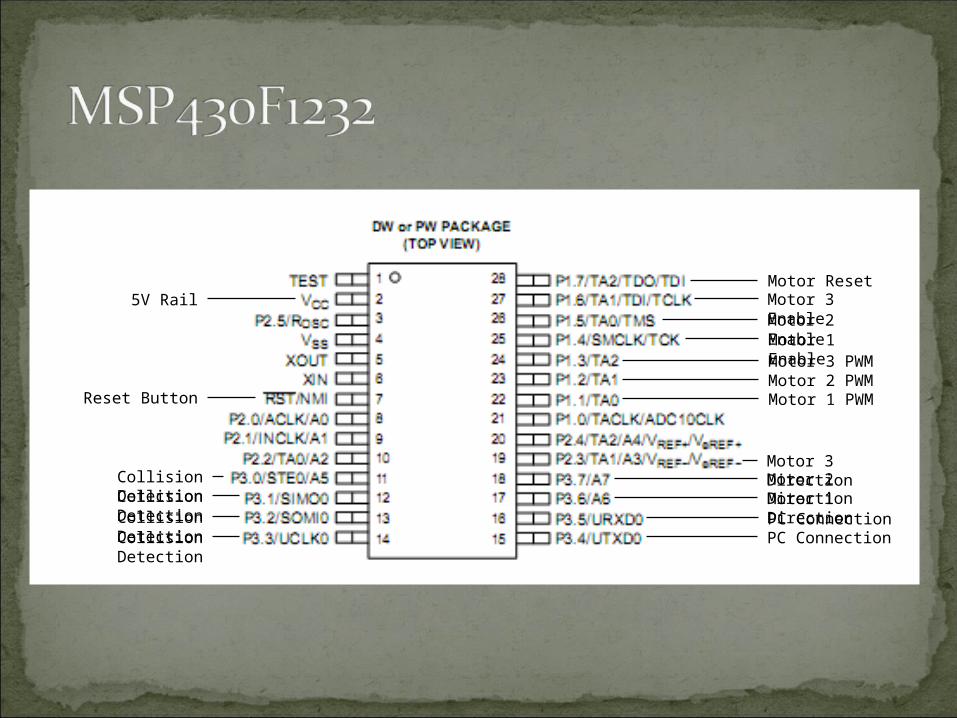
5V Rail
Reset Button Motor 1 PWMMotor 2 PWMMotor 3 PWMMotor 1 Enable
Motor 2 Enable
Motor 3 Enable
Motor 1 Direction
Motor 2 Direction
Motor 3 Direction
PC ConnectionPC Connection
Motor Reset
Collision Detection
Collision Detection
Collision Detection
Collision Detection

Motor Control3 PWMs (Square Waves) – 3 Motors
Speed – Period of wavesDistance – Duration of signal
Marker ControlControlled by Marker Wheel attached with
Stepper MotorSignal will enable the wheel to rotate until
marker in DOWN position.
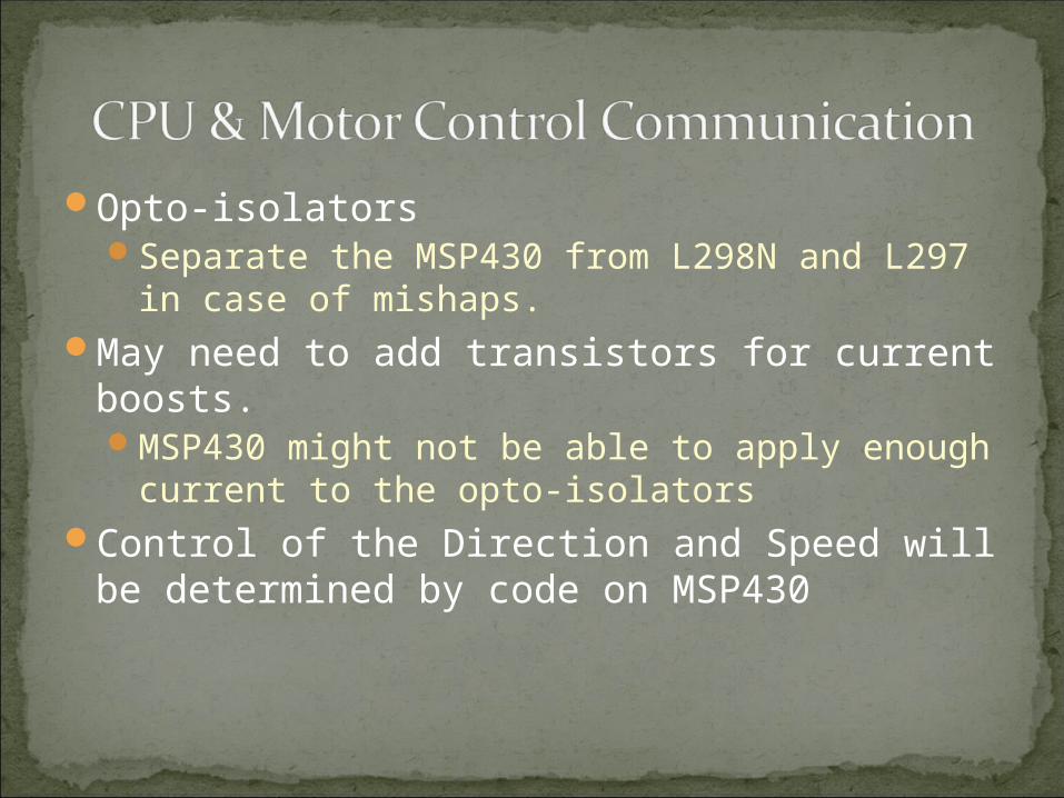
Opto-isolatorsSeparate the MSP430 from L298N and L297 in
case of mishaps.May need to add transistors for current
boosts.MSP430 might not be able to apply enough
current to the opto-isolatorsControl of the Direction and Speed will be
determined by code on MSP430
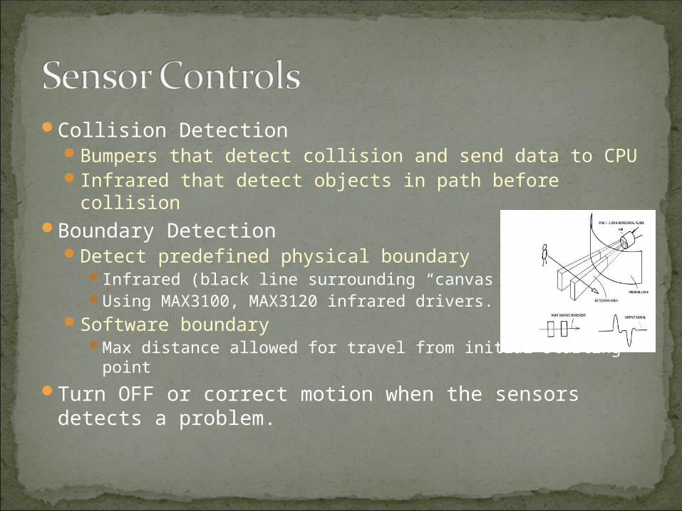
Collision DetectionBumpers that detect collision and send data to CPUInfrared that detect objects in path before collision
Boundary DetectionDetect predefined physical boundary
Infrared (black line surrounding “canvas”)Using MAX3100, MAX3120 infrared drivers.
Software boundaryMax distance allowed for travel from initial starting point
Turn OFF or correct motion when the sensors detects a problem.
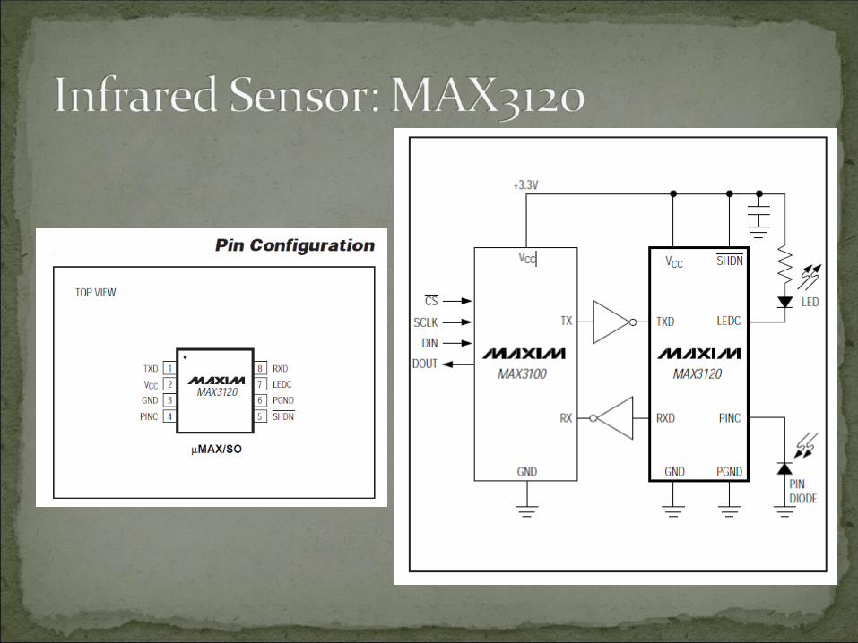

3 to 5.5V operating voltage.1 CM to 1 M detection range.High accuracy (built-in narrow band pass
filter).Compatible with MAX3100 (IR to UART Data
Link).Schmitt Trigger input/output operation.

Power Control BoardProvide 50V for the stepper motor, 7V for the
logic circuitry (motor driver), and 2V for the MSP430 CPU chip.
Isolation circuit using opto-isolators MAX232IN for providing current to motor.
Power monitoring and reporting controlled by MSP430.
Conservation of power by shutting down components not being used by controlling the signal to the enable pin in the motor driver.
Rechargeable battery.


Task Peter Erik Niket Chris
MechanicalChassis/Mounts X
Electrical
Input Controls X
Motor Controls X X
CPU/Power Management
X X X X
Marker/Sensors X X
Software
CPU X X
UI Software X X
Integration X X X X
Manufacturing X X
Testing X X X X
Documentation X X X X
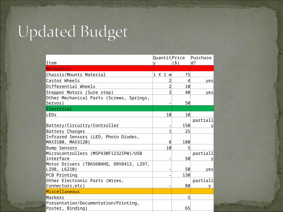
Item Quantity Price ($) Purchased?Mechanical Chassis/Mounts Material 1 X 1 m 75 Castor Wheels 2 4 yesDifferential Wheels 2 10 Stepper Motors (Sure step) 3 40 yesOther Mechanical Parts (Screws, Springs, Servos) - 50 Electrical LEDs 10 10 Battery/Circuitry/Controller - 150 partiallyBattery Charger 1 25 Infrared Sensors (LED, Photo Diodes, MAX3100, MAX3120) 8 180 Bump Sensors 10 5 Microcontrollers (MSP430F1232IPW)/USB interface - 50 partiallyMotor Drivers (TB6560AHQ, DRV8412, L297, L298, L6210) - 50 yesPCB Printing - 130 Other Electronic Parts (Wires, Connectors,etc) - 80 partially Miscellaneous Markers 5 Presentation/Documentation(Printing, Poster, Binding) 65 Total 929

Signal/Power Noise Opto-Isolators, separate regulators purchased
Motor Accuracy Loose Contacts between wheel and ground – Slowly
build up the speed to avoid loose contact. Inaccurate stepping by motor – High current keeps steps
accuratePower management surges and spikes
Opto-IsolatorsLose communication with robot
Range - Software controlled Power OFF Loose wiring – Effective Build Up
Uncertainty in learning curveUncertainty in parts availability and deliveryUnfamiliar technology