Embed Size (px)
Citation preview

1
NIPPON PAPER
RO SYSTEM
+
2 Others
March 2014
Greg WyrickDistrict Account Manager
John ZoraDistrict Account Manager
2
Purpose: Review the design, function, layout, and operation of the ROsystem.
Process: 30-40 minute presentation.
Payoff: Gain a better understanding of the RO system
3
But First, What is RO?
RO: Reverse Osmosis

4
Osmotic Head
Pure Water
StrongSolution
H2O
H2O
H2O
Pure Water Flow
Semi-Permeable Membrane
NaCl
Na+ Cl-
Osmosis
5
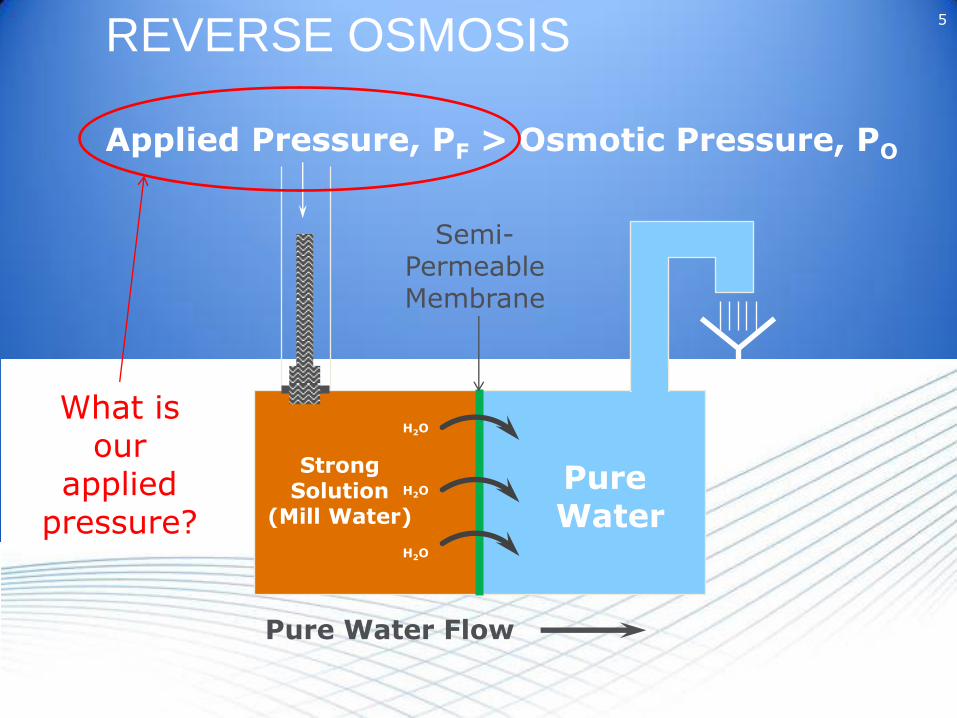
REVERSE OSMOSIS
Applied Pressure, PF > Osmotic Pressure, PO
H2O
H2O
H2O
StrongSolution
(Mill Water)
Pure Water Flow
Pure Water
Semi-PermeableMembrane
What is our
applied pressure?

6
WHY RO at Nippon?
Old Boiler: 225 PSIGZeolite Softened WaterNo TurbinePaper Mill Steam Use
Cogen Boiler: 900 PSIG20 MW TurbineSteam Extraction + Condensing
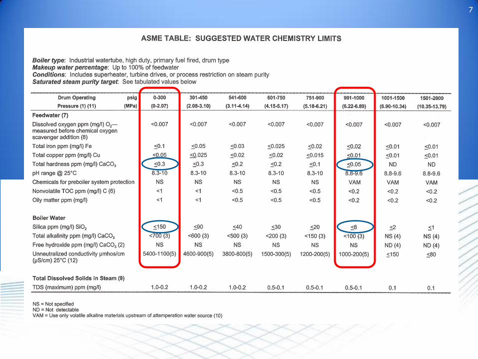
7
8
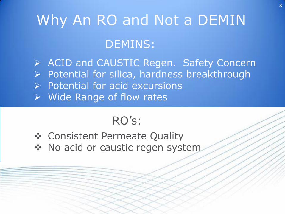
Why An RO and Not a DEMIN
ACID and CAUSTIC Regen. Safety Concern Potential for silica, hardness breakthrough Potential for acid excursions Wide Range of flow rates
DEMINS:
Consistent Permeate Quality No acid or caustic regen system
RO’s:

Filter Plant
31-1300-PMP
LocalSample
Boiler Make-up Filters (3)
31-130531-131031-1315
MMF’s
Water Softeners (2) & Brine Tank
31-133031-1335
Nalco7408
InjectionQuill
LocalSample
31-1320
LocalSample
Concentrate
ROProduct
Qty: 2
Qty: 4
Reverse Osmosis Units (2)Mixed Bed Polisher
31-1355
LocalSample
Boiler MakeupWater Tank
31-1360
Boiler MakeupWater Pumps (2)
31-136531-1370
Boiler MakeupWater Heat Exchanger31-1770
LocalSample
50#Steam
NalcoConquorCNQR3475
Condensate Polisher (2) & Brine Tank
31-126031-1270 31-1280
Sample to Test Station
Sample to Test Station
Sample to Test Station
ProcessCondensate
Condensing EconomizerFlue Gas Chamber:
31-700
Surface CondenserCondensate HighTemperature HeatExchanger: 31-1705
Soot BlowerCondensate
Steam From Turbine
Surface Condenser:32-1400
Surface CondenserSteam Eductor System
32-1410
Final Inter
Gland SteamCondenser32-1030
Surface CondenserCondensate Low TempHeat Exchanger
31-1775
To Vacuum DrainFlash Tank
To BFW Pumps
Nalco1820
Nippon Paper Cogen BoilerPretreatment System

ElwhaRiver
Treat-mentPlant
Mill FilterPlant
RO Water TreatmentBuilding
StorageTank
Deaerator
Basic Block Diagram of Water Flow
BOILER
SteamTurbineCond.
Cond.Polisher
Paper MillCond.

Basic Block Diagram of RO TREATMENT BUILDING
RoundTankMillWater
BoosterPump
HighEfficiencyFilters
Softeners
RO’sMixedBedPolishers
StorageTank
12
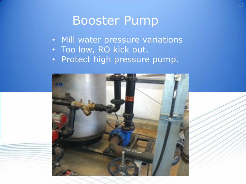
Booster Pump
• Mill water pressure variations• Too low, RO kick out.• Protect high pressure pump.

13
High Efficiency Filters

14
High Efficiency Filters
Purpose:• Remove un-dissolved solids• Particles larger than 0.5 microns
Process:Pass water through a high efficiency filter
Payoff:• Produce water of SDI less than 5• Minimize RO Fouling

15
Standard Multi-Media FilterUltraSand Plus
High Efficiency Filter
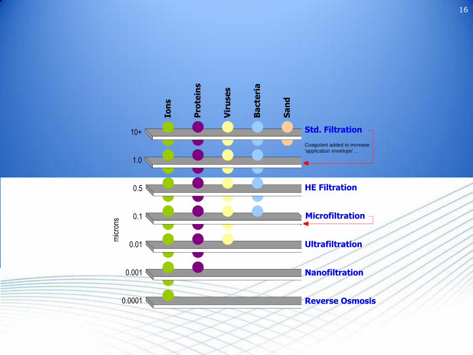
16
0.0001
1.0
0.1
0.01
0.001
mic
rons
Ion
s
Pro
tein
s
Vir
use
s
Ba
cte
ria
Sa
nd
10+ Std. Filtration
Microfiltration
Ultrafiltration
Nanofiltration
Reverse Osmosis
Ba
cte
ria
Sa
nd
Coagulant
Addition
Coagulant added to increase
'application envelope'...
0.5 HE Filtration
0.0001
1.0
0.1
0.01
0.001
mic
rons
Ion
s
Pro
tein
s
Vir
use
s
Ba
cte
ria
Sa
nd
10+ Std. Filtration
Microfiltration
Ultrafiltration
Nanofiltration
Reverse Osmosis
Ba
cte
ria
Sa
nd
Coagulant
Addition
Coagulant added to increase
'application envelope'...
0.5 HE Filtration

17
Top Over Bottom (TOB):
Feed water enters and creates an area of turbulence over the bed and a tangential force that scrubs particles off the bed surface.
The tangential force carries particles back toward the filter inlet. At the same time, this tangential force also pushes sand towards the filter inlet, creating a “camel hump.”
Behind this “hump” is an area of low turbulence that allows for deposition of particles that have been scrubbed off of the sand.
This low-turbulence area keeps filling with particles until spilling over the “hump” into the high-turbulence area of the filter.

18
Top Over Bottom (TOB):
As particles begin to collect on the turbulent-side of the “hump’ adds to the particle loading of the influent water.
When the loading of solids in the feed water exceeds the capacity of the water to hold them, the particles begin to drop out on the filter bed,
This increases the differential pressure through the bed, signaling time to backwash the filter.
Filters are backwashed when the differential pressure reaches 15 psig.
Ref: Pg. 12

19
This is all great, but the mill has a filter plantWhy does it need a High Efficiency Filter
SDI
SILT DENSITY INDEX

20
SDI TesterPressure Gauge Filter Holder,
0.45 micron, 47 mm

21

22
Silt Density Index
Measures Fouling potential of RO membranes with suspended solids.
Higher the number, the greater the potential.
Most membrane manufactures require an SDI below 5 for warranty.

23
SDI =1 – (ti/tf) x 100
T
Where: ti = initial time to fill to 500 mltf = time after T to fill to 500 mlT = Time, usually 15 minutes.

24
BASELINE DATA COLLECTION
From October 2010 to September 2012
SDI were ran 14 times.
Values ranged from 18 - 90
Far too high for an RONeed to a high efficiency filter

25
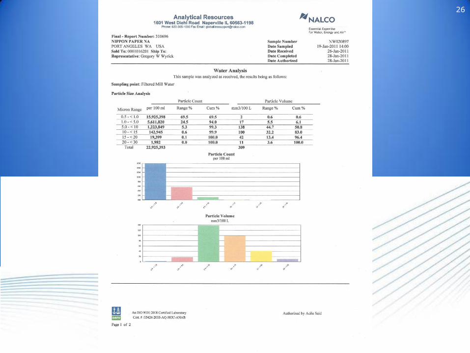
PARTICLE SIZE DISTRIBUTION
Sample sent to a lab, analyze for particle counts and volumes with proscribed micron ranges.
From October 2010 to October 2012, 20 samples sent in to establish baseline.
26

27
How Well Does the Filter Work
Effluent: SDI = 3.1 Influent: SDI = 18
February 10, 2014
28
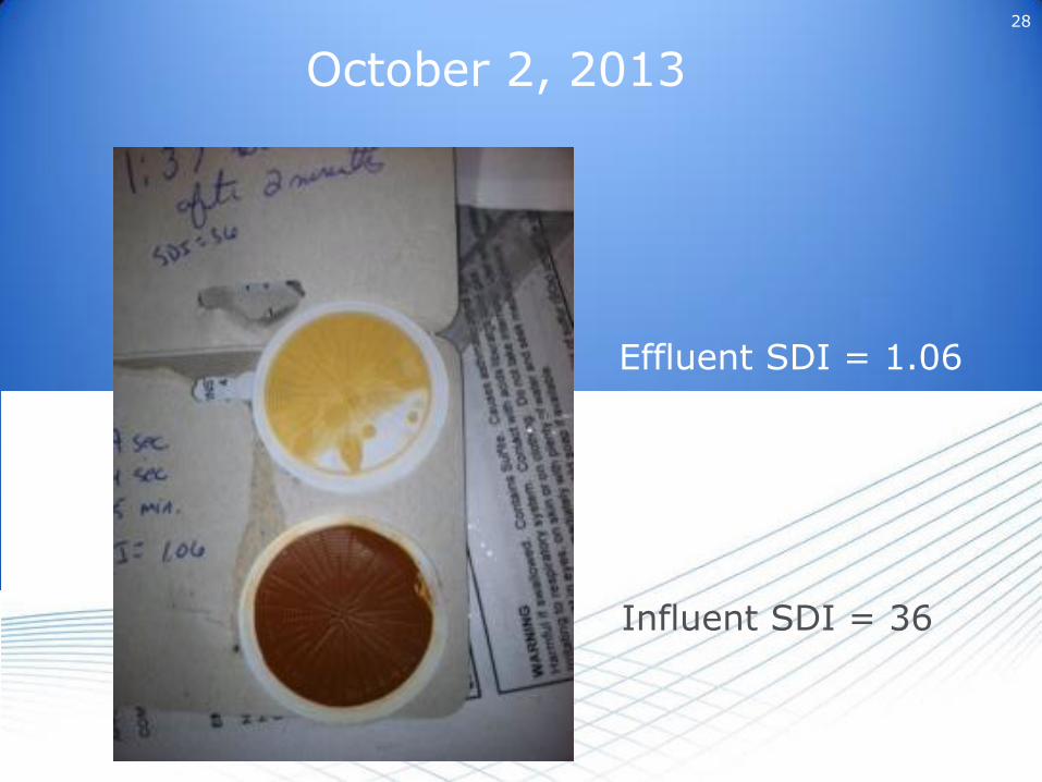
October 2, 2013
Influent SDI = 36
Effluent SDI = 1.06

29
PSD Data
Range, micron Particle % removal Volume % removal
0.5 - 1 70% 71%
1 – 5 98% 99%
5 – 10 99.7% 99.7
10 - 15 99% 99%
15 – 20 99% 99%
20 – 30 98% 99%
Total n/a 99%

30
Operations
• All 3 run at a time.• Booster pump starts when there is a
call for water, ie level is make-up water tank.
• Backwash based on differential pressure.
• Automatically backwash in sequence once differential pressure is reached.
• Takes 8 minutes per unit.

31
Softeners
Purpose: Remove hardness.
Process: Pass water over cation resin.
Payoff: Protect RO from hardness based scale & no need to add an anti-scalant.
32
Operations
• 2 units: one in service; one standby• Scavenge Chlorine out• Run to a gallons throughput• Auto switch• Auto regenerate.• Operators keep brine tank full of salt

33
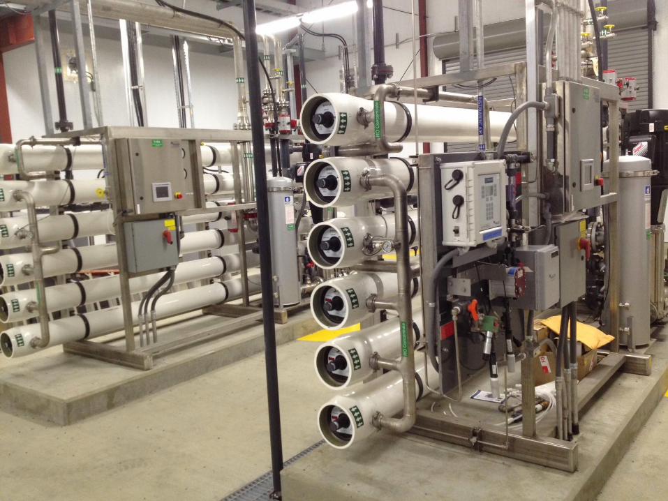
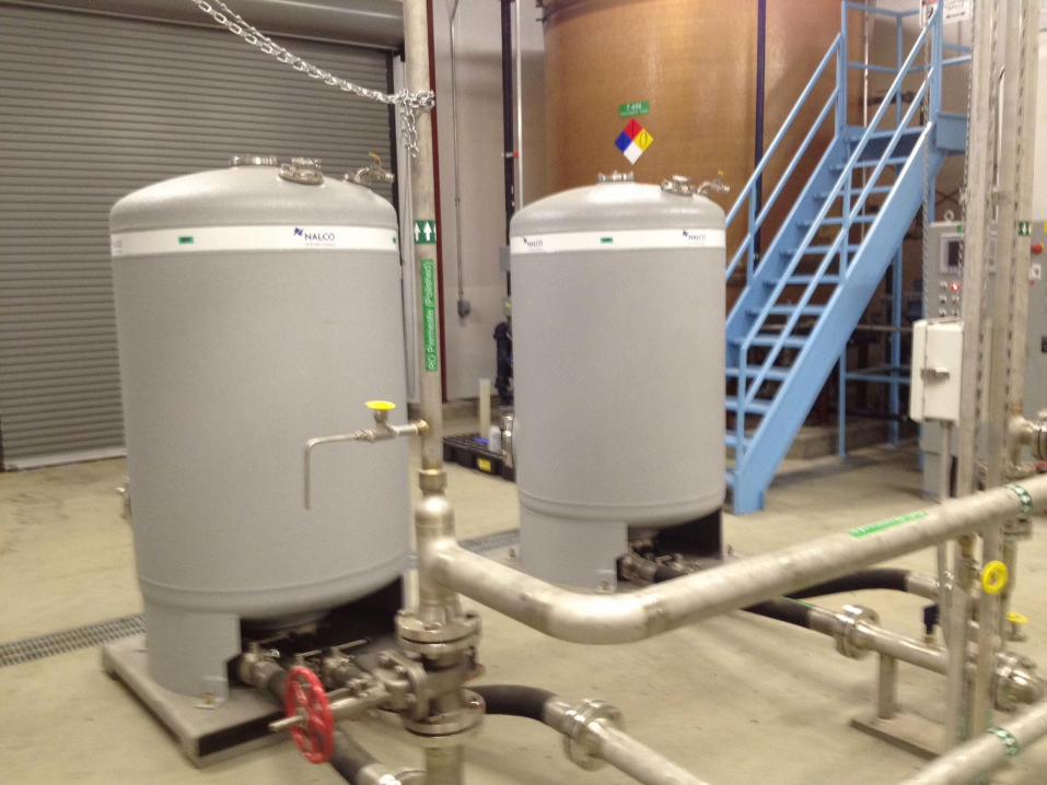
RO

3 Basic Components1. Prefilter - Red2. Pump - Yellow3. RO Membranes - Blue

35
Purpose: Remove dissolved ions and colloidal silica from water to condition water for use as boiler feed water.
Process: Water is passed through a semi-permeable membrane.
Payoff: Water is almost good enough for economical use as BFW. Last step is to pass through a mixed bed polisher.

2:1 Array System
168 gpm
84 gpm
84 gpm
42 gpm
42 gpm
42 gpm
42 gpm
84 gpm
84 gpm
42 gpm
42 gpm
126 gpm
Permeate
Concentrateto sewer
75% Recovery25% Rejection

37
38
39
40

41

42
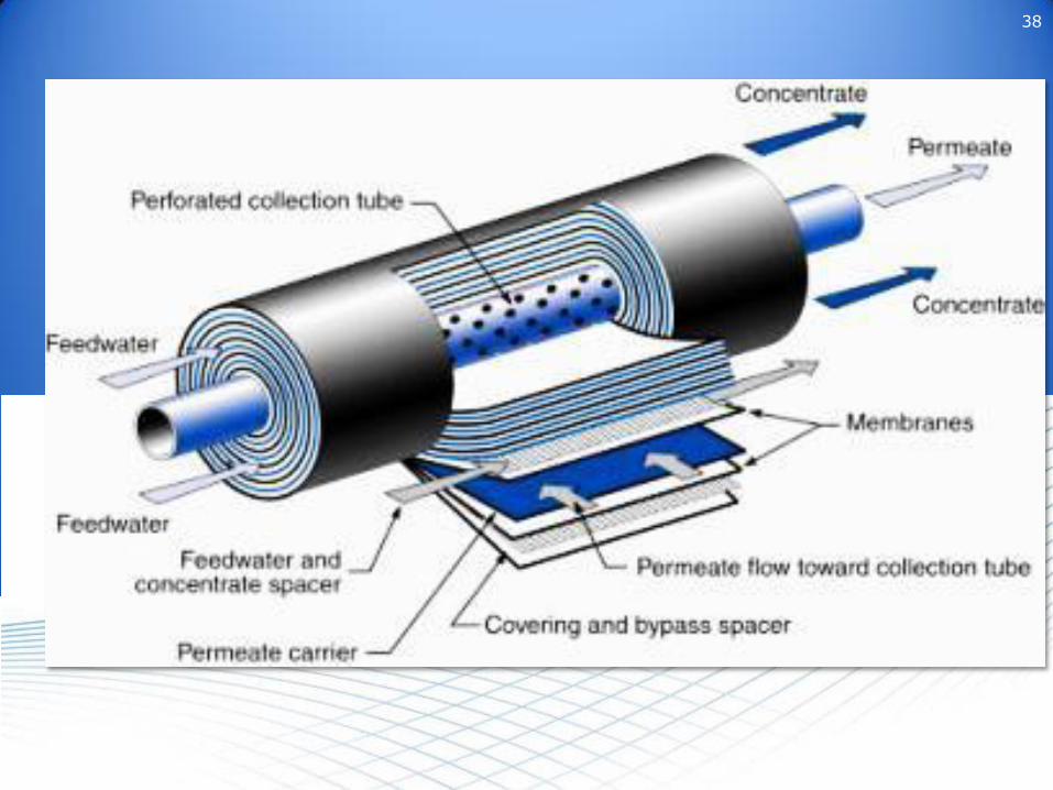
Membrane leaf
Permeate spacer
Feed spacer

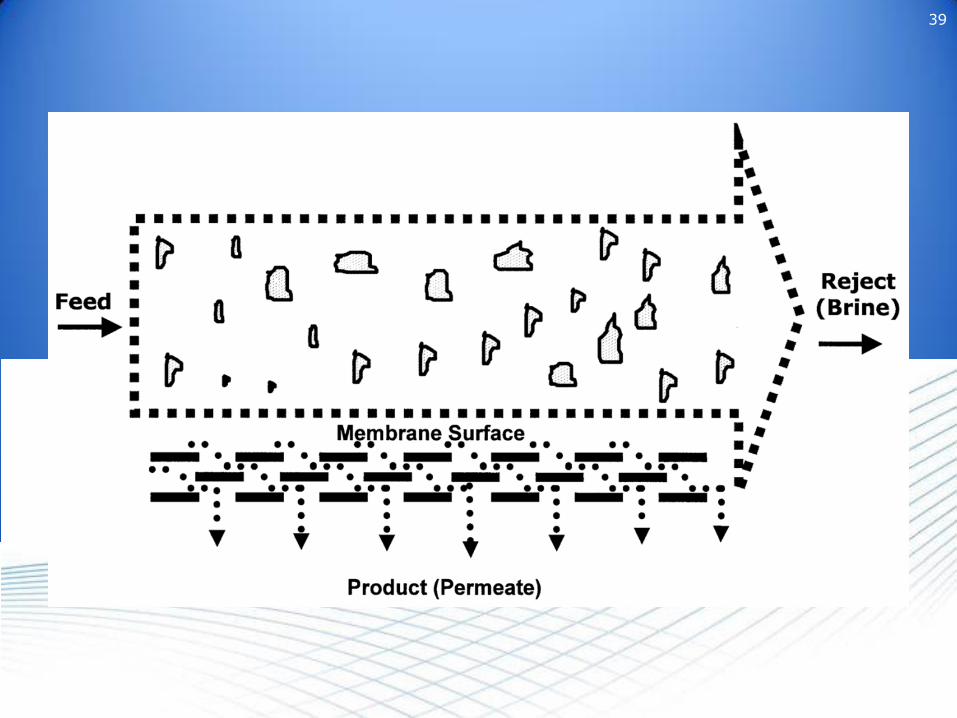
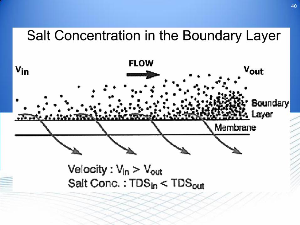
• As the feed water travels down the membrane(s), it becomes more concentrated:
Product
ConcentrateFeed
Brine becomes more concentrated

• Pressure Vessel:
– Multi-Module Pressure Vessel-
44
Product[Permeate]
Concentrate[Reject]
Feed
Contains 1, 3, 4, 6, or 7 modules in series

45
• TFC Membrane:
0.2 micron40 micron
120 micronReinforcing Fabric
Microporous Polysulfone
PolyamideUltra-thin
Barrier Layer
Flow always goes INTO the structure
REVERSE FLOW WILL LIFT THE MEMBRANE FROM THE BACKING

46
Polyamide Barrier Layer
Polysulfone Backing
Support Layer
TFC Membrane
46

47
Mixed Bed Polisher
• After RO• Remove any ions (hardness, silica) that
gets past the RO.

48
Mill Water:
Silica: Ave. 6.8 ppm; low: 5.5, high 9.098% rejection from ROSilica in permeate = 0.136 ppm Ave.
0.11 ppm Low0.18 ppm High
At 50 cycles:6.8 ppm Ave.5.5 ppm Low9 ppm HighUpper boiler limit for silica is 8 ppm

49
Silica: Ave. 6.8 ppm; low: 5.5, high 9.095% rejection from ROSilica in permeate = 0.34 ppm Ave.
0.275 ppm Low0.45 ppm High
At 50 cycles:17 ppm Ave.13.8 ppm Low22.5 ppm HighUpper boiler limit for silica is 8 ppm
Can not run at 50 cycles. Have to increase blowdown and run at 23 cycles.
50
Control and Monitoring


Inhibitor Control
pH
ORP
Temperature
NTU
Pressures
Flow


Automated Tank Level and Usage Reporting
58
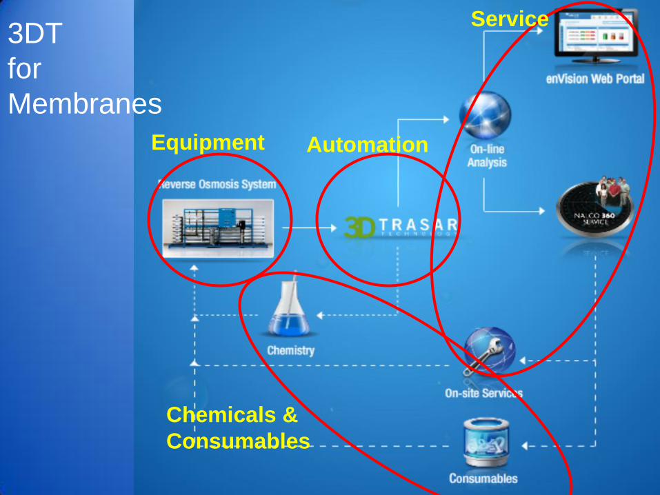
Automation
Chemicals &
Consumables
Service
Equipment
3DT
for
Membranes

Immediate Feedback of Problems
3DTTfM
Monitoring
Customer
Notifications!

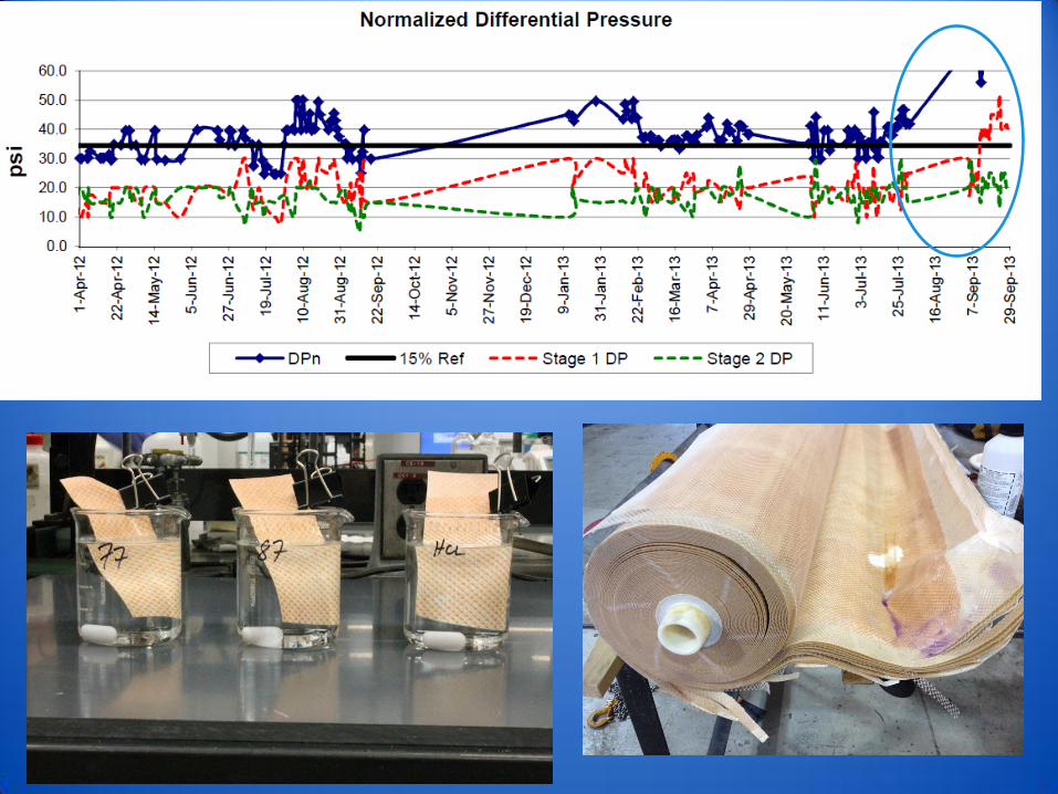
Cleaning at the right time
Cleaning
should have
been done
here
Inneffective
cleanings

Multiple data streams come into a central unit
Concentrate
Permeate
Feed Water
F FuS uSP
P
P
P
TFL
FL
PP
O pH


Weekly Operations Report
64
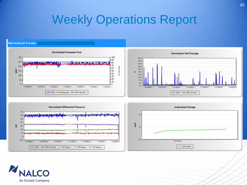
Weekly Operations Report
65

66
THANK YOU!


![Nippon Denko Compendium 2017eng).pdf · Nippon Denko Compendium 2017 ... additives for laminated ceramic capacitors, ... [European market and FV]; TEX Report [others]) Product prices](https://img.pdfslide.net/doc/110x75/5b5bef057f8b9a68368bb676/nippon-denko-compendium-engpdf-nippon-denko-compendium-2017-additives.jpg)