Embed Size (px)
DESCRIPTION
Nissan Cube engine repair manual
Citation preview
ENGINE
C
D
E
SECTION ECA
EC
ENGINE CONTROL SYSTEM
F
G
H
I
J
K
L
M
N
O
P
CONTENTS
MR18DE
BASIC INSPECTION .................................... 8
DIAGNOSIS AND REPAIR WORK FLOW ......... 8Work Flow .................................................................8Diagnostic Work Sheet ............................................11
INSPECTION AND ADJUSTMENT ....................12
BASIC INSPECTION .................................................12BASIC INSPECTION : Special Repair Require-ment ........................................................................12
ADDITIONAL SERVICE WHEN REPLACING CONTROL UNIT ........................................................15
ADDITIONAL SERVICE WHEN REPLACING CONTROL UNIT : Description ................................15ADDITIONAL SERVICE WHEN REPLACING CONTROL UNIT : Special Repair Requirement .....15
IDLE SPEED ..............................................................15IDLE SPEED : Description ......................................15IDLE SPEED : Special Repair Requirement ...........16
IGNITION TIMING ......................................................16IGNITION TIMING : Description ..............................16IGNITION TIMING : Special Repair Requirement ....16
VIN REGISTRATION .................................................16VIN REGISTRATION : Description .........................16VIN REGISTRATION : Special Repair Require-ment ........................................................................16
ACCELERATOR PEDAL RELEASED POSITION LEARNING ................................................................17
ACCELERATOR PEDAL RELEASED POSITION LEARNING : Description .........................................17ACCELERATOR PEDAL RELEASED POSITION LEARNING : Special Repair Requirement ..............17
THROTTLE VALVE CLOSED POSITION LEARN-ING .............................................................................17
THROTTLE VALVE CLOSED POSITION LEARNING : Description .........................................17THROTTLE VALVE CLOSED POSITION LEARNING : Special Repair Requirement ..............17
IDLE AIR VOLUME LEARNING ................................17IDLE AIR VOLUME LEARNING : Description .........17IDLE AIR VOLUME LEARNING : Special Repair Requirement ............................................................17
MIXTURE RATIO SELF-LEARNING VALUE CLEAR .......................................................................19
MIXTURE RATIO SELF-LEARNING VALUE CLEAR : Description ................................................19MIXTURE RATIO SELF-LEARNING VALUE CLEAR : Special Repair Requirement .....................19
SYSTEM DESCRIPTION .............................21
ENGINE CONTROL SYSTEM ..........................21System Diagram .....................................................21System Description ..................................................22Component Parts Location ....................................22Component Description ...........................................27
MULTIPORT FUEL INJECTION SYSTEM .......28System Diagram .....................................................28System Description ..................................................28Component Parts Location ....................................31Component Description ...........................................36
ELECTRIC IGNITION SYSTEM ........................37System Diagram .....................................................37System Description ..................................................37Component Parts Location ....................................38Component Description ...........................................43
AIR CONDITIONING CUT CONTROL ..............44System Diagram ......................................................44System Description ..................................................44Component Parts Location ....................................45Component Description ...........................................50
EC-1Revision: 2009 March 2009 Z12
AUTOMATIC SPEED CONTROL DEVICE (ASCD) ............................................................... 51
System Diagram ..................................................... 51System Description ................................................. 51Component Parts Location ................................... 53Component Description ......................................... 58
CAN COMMUNICATION ................................... 59System Description ................................................. 59
COOLING FAN CONTROL ............................... 60System Diagram ..................................................... 60System Description ................................................. 60Component Parts Location ................................... 62Component Description .......................................... 67
EVAPORATIVE EMISSION SYSTEM ............... 68System Diagram ..................................................... 68System Description ................................................. 68Component Parts Location ................................... 72Component Description ......................................... 77
INTAKE VALVE TIMING CONTROL ................. 78System Diagram ..................................................... 78System Description ................................................. 78Component Parts Location ................................... 79Component Description .......................................... 84
ON BOARD DIAGNOSTIC (OBD) SYSTEM ..... 85Diagnosis Description ............................................. 85CONSULT-III Function ........................................... 98Diagnosis Tool Function ......................................106
DTC/CIRCUIT DIAGNOSIS ........................109
TROUBLE DIAGNOSIS - SPECIFICATION VALUE ............................................................. 109
Description .............................................................109Component Function Check ..................................109Diagnosis Procedure .............................................110
POWER SUPPLY AND GROUND CIRCUIT ... 117Diagnosis Procedure .............................................117
U0101 CAN COMM CIRCUIT .......................... 120Description .............................................................120DTC Logic ..............................................................120Diagnosis Procedure .............................................120
U0140 CAN COMM CIRCUIT .......................... 121Description .............................................................121DTC Logic ..............................................................121Diagnosis Procedure .............................................121
U1001 CAN COMM CIRCUIT .......................... 122Description .............................................................122DTC Logic ..............................................................122Diagnosis Procedure .............................................122
P0011 IVT CONTROL ...................................... 123DTC Logic ..............................................................123
Diagnosis Procedure ............................................. 124Component Inspection .......................................... 125
P0031, P0032 A/F SENSOR 1 HEATER ..........127Description ............................................................ 127DTC Logic ............................................................. 127Diagnosis Procedure ............................................. 127Component Inspection .......................................... 129
P0037, P0038 HO2S2 HEATER .......................130Description ............................................................ 130DTC Logic ............................................................. 130Diagnosis Procedure ............................................. 131Component Inspection .......................................... 132
P0075 IVT CONTROL SOLENOID VALVE ......133Description ............................................................ 133DTC Logic ............................................................. 133Diagnosis Procedure ............................................. 133Component Inspection .......................................... 134
P0101 MAF SENSOR .......................................136Description ............................................................ 136DTC Logic ............................................................. 136Component Function Check ................................. 137Diagnosis Procedure ............................................. 138Component Inspection .......................................... 139
P0102, P0103 MAF SENSOR ..........................143Description ............................................................ 143DTC Logic ............................................................. 143Diagnosis Procedure ............................................. 144Component Inspection .......................................... 145
P0112, P0113 IAT SENSOR ............................148Description ............................................................ 148DTC Logic ............................................................. 148Diagnosis Procedure ............................................. 148Component Inspection .......................................... 149
P0116 ECT SENSOR .......................................150Description ............................................................ 150DTC Logic ............................................................. 150Diagnosis Procedure ............................................. 151Component Inspection .......................................... 151
P0117, P0118 ECT SENSOR ...........................152Description ............................................................ 152DTC Logic ............................................................. 152Diagnosis Procedure ............................................. 152Component Inspection .......................................... 153
P0122, P0123 TP SENSOR ..............................155Description ............................................................ 155DTC Logic ............................................................. 155Diagnosis Procedure ............................................. 155Component Inspection .......................................... 157Special Repair Requirement ................................. 157
P0125 ECT SENSOR .......................................158Description ............................................................ 158
EC-2Revision: 2009 March 2009 Z12
C
D
E
F
G
H
I
J
K
L
M
C
A
N
O
P
E
DTC Logic ............................................................. 158Diagnosis Procedure ............................................. 159Component Inspection .......................................... 159
P0127 IAT SENSOR ......................................... 161Description ............................................................ 161DTC Logic ............................................................. 161Diagnosis Procedure ............................................. 162Component Inspection .......................................... 162
P0128 THERMOSTAT FUNCTION .................. 163DTC Logic ............................................................. 163Diagnosis Procedure ............................................. 163Component Inspection .......................................... 164
P0130 A/F SENSOR 1 ...................................... 165Description ............................................................ 165DTC Logic ............................................................. 165Component Function Check .................................. 166Diagnosis Procedure ............................................. 167
P0131 A/F SENSOR 1 ...................................... 169Description ............................................................ 169DTC Logic ............................................................. 169Diagnosis Procedure ............................................. 170
P0132 A/F SENSOR 1 ...................................... 172Description ............................................................ 172DTC Logic ............................................................. 172Diagnosis Procedure ............................................. 173
P0133 A/F SENSOR 1 ...................................... 175Description ............................................................ 175DTC Logic ............................................................. 175Diagnosis Procedure ............................................. 177
P0137 HO2S2 ................................................... 180Description ............................................................ 180DTC Logic ............................................................. 180Component Function Check .................................. 181Diagnosis Procedure ............................................. 182Component Inspection .......................................... 183
P0138 HO2S2 ................................................... 186Description ............................................................ 186DTC Logic ............................................................. 186Component Function Check .................................. 187Diagnosis Procedure ............................................. 188Component Inspection .......................................... 191
P0139 HO2S2 ................................................... 194Description ............................................................ 194DTC Logic ............................................................. 194Component Function Check .................................. 195Diagnosis Procedure ............................................. 196Component Inspection .......................................... 197
P0171 FUEL INJECTION SYSTEM FUNC-TION ................................................................. 200
DTC Logic ............................................................. 200Diagnosis Procedure ............................................. 201
P0172 FUEL INJECTION SYSTEM FUNC-TION ................................................................ 204
DTC Logic ..............................................................204Diagnosis Procedure .............................................205
P0181 FTT SENSOR ....................................... 208Description .............................................................208DTC Logic ..............................................................208Diagnosis Procedure .............................................209Component Inspection ...........................................210
P0182, P0183 FTT SENSOR .......................... 211Description .............................................................211DTC Logic ..............................................................211Diagnosis Procedure .............................................211Component Inspection ...........................................212
P0222, P0223 TP SENSOR ............................ 214Description .............................................................214DTC Logic ..............................................................214Diagnosis Procedure .............................................214Component Inspection ...........................................216Special Repair Requirement ..................................216
P0300, P0301, P0302, P0303, P0304 MIS-FIRE ................................................................. 217
DTC Logic ..............................................................217Diagnosis Procedure .............................................218
P0327, P0328 KS ............................................ 223Description .............................................................223DTC Logic ..............................................................223Diagnosis Procedure .............................................223Component Inspection ...........................................224
P0335 CKP SENSOR (POS) ........................... 225Description .............................................................225DTC Logic ..............................................................225Diagnosis Procedure .............................................226Component Inspection ...........................................228
P0340 CMP SENSOR (PHASE) ..................... 229Description .............................................................229DTC Logic ..............................................................229Diagnosis Procedure .............................................230Component Inspection ...........................................231
P0420 THREE WAY CATALYST FUNCTION . 233DTC Logic ..............................................................233Component Function Check ..................................234Diagnosis Procedure .............................................234
P0441 EVAP CONTROL SYSTEM ................. 238DTC Logic ..............................................................238Component Function Check ..................................239Diagnosis Procedure .............................................240Component Inspection (Drain filter) .......................243
P0442 EVAP CONTROL SYSTEM ................. 244DTC Logic ..............................................................244Diagnosis Procedure .............................................245
EC-3Revision: 2009 March 2009 Z12
Component Inspection (Fuel filler cap) ..................249Component Inspection (Drain filter) .......................249
P0443 EVAP CANISTER PURGE VOLUME CONTROL SOLENOID VALVE ....................... 251
Description .............................................................251DTC Logic ..............................................................251Diagnosis Procedure .............................................252Component Inspection ...........................................254
P0444, P0445 EVAP CANISTER PURGE VOLUME CONTROL SOLENOID VALVE ...... 256
Description .............................................................256DTC Logic ..............................................................256Diagnosis Procedure .............................................256Component Inspection ...........................................258
P0447 EVAP CANISTER VENT CONTROL VALVE ............................................................. 259
Description .............................................................259DTC Logic ..............................................................259Diagnosis Procedure .............................................259Component Inspection ...........................................261
P0448 EVAP CANISTER VENT CONTROL VALVE ............................................................. 263
Description .............................................................263DTC Logic ..............................................................263Diagnosis Procedure .............................................264Component Inspection ...........................................265
P0451 EVAP CONTROL SYSTEM PRES-SURE SENSOR ............................................... 267
Description .............................................................267DTC Logic ..............................................................267Diagnosis Procedure .............................................267Component Inspection ...........................................269
P0452 EVAP CONTROL SYSTEM PRES-SURE SENSOR ............................................... 270
Description .............................................................270DTC Logic ..............................................................270Diagnosis Procedure .............................................271Component Inspection ...........................................274
P0453 EVAP CONTROL SYSTEM PRES-SURE SENSOR ............................................... 275
Description .............................................................275DTC Logic ..............................................................275Diagnosis Procedure .............................................276Component Inspection ...........................................279
P0455 EVAP CONTROL SYSTEM .................. 281DTC Logic ..............................................................281Diagnosis Procedure .............................................282Component Inspection (Fuel filler cap) ..................285Component Inspection (Drain filter) .......................286
P0456 EVAP CONTROL SYSTEM .................. 287DTC Logic ..............................................................287
Component Function Check ................................. 289Diagnosis Procedure ............................................. 289Component Inspection (Fuel filler cap) ................. 292Component Inspection (Drain filter) ...................... 293
P0460 FUEL LEVEL SENSOR .........................294Description ............................................................ 294DTC Logic ............................................................. 294Diagnosis Procedure ............................................. 294
P0461 FUEL LEVEL SENSOR .........................295Description ............................................................ 295DTC Logic ............................................................. 295Component Function Check ................................. 295Diagnosis Procedure ............................................. 296
P0462, P0463 FUEL LEVEL SENSOR ............297Description ............................................................ 297DTC Logic ............................................................. 297Diagnosis Procedure ............................................. 297
P0500 VSS ........................................................299Description ............................................................ 299DTC Logic ............................................................. 299Component Function Check ................................. 300Diagnosis Procedure ............................................. 300
P0506 ISC SYSTEM .........................................301Description ............................................................ 301DTC Logic ............................................................. 301Diagnosis Procedure ............................................. 301
P0507 ISC SYSTEM .........................................303Description ............................................................ 303DTC Logic ............................................................. 303Diagnosis Procedure ............................................. 303
P0605 ECM .......................................................305Description ............................................................ 305DTC Logic ............................................................. 305Diagnosis Procedure ............................................. 306
P0607 ECM .......................................................307Description ............................................................ 307DTC Logic ............................................................. 307Diagnosis Procedure ............................................. 307
P0643 SENSOR POWER SUPPLY ..................308DTC Logic ............................................................. 308Diagnosis Procedure ............................................. 308
P0850 PNP SWITCH ........................................310Description ............................................................ 310DTC Logic ............................................................. 310Component Function Check ................................. 311Diagnosis Procedure ............................................. 311
P1148 CLOSED LOOP CONTROL ..................313DTC Logic ............................................................. 313
P1212 TCS COMMUNICATION LINE ..............314Description ............................................................ 314
EC-4Revision: 2009 March 2009 Z12
C
D
E
F
G
H
I
J
K
L
M
C
A
N
O
P
E
DTC Logic ............................................................. 314Diagnosis Procedure ............................................. 314
P1217 ENGINE OVER TEMPERATURE ......... 315DTC Logic ............................................................. 315Component Function Check .................................. 315Diagnosis Procedure ............................................. 316
P1225 TP SENSOR .......................................... 319Description ............................................................ 319DTC Logic ............................................................. 319Diagnosis Procedure ............................................. 319Special Repair Requirement ................................. 320
P1226 TP SENSOR .......................................... 321Description ............................................................ 321DTC Logic ............................................................. 321Diagnosis Procedure ............................................. 321Special Repair Requirement ................................. 322
P1421 COLD START CONTROL ..................... 323Description ............................................................ 323DTC Logic ............................................................. 323Diagnosis Procedure ............................................. 323
P1550 BATTERY CURRENT SENSOR ........... 325Description ............................................................ 325DTC Logic ............................................................. 325Diagnosis Procedure ............................................. 326Component Inspection .......................................... 327
P1551, P1552 BATTERY CURRENT SEN-SOR .................................................................. 329
Description ............................................................ 329DTC Logic ............................................................. 329Diagnosis Procedure ............................................. 330Component Inspection .......................................... 331
P1553 BATTERY CURRENT SENSOR ........... 333Description ............................................................ 333DTC Logic ............................................................. 333Diagnosis Procedure ............................................. 334Component Inspection .......................................... 335
P1554 BATTERY CURRENT SENSOR ........... 337Description ............................................................ 337DTC Logic ............................................................. 337Component Function Check .................................. 337Diagnosis Procedure ............................................. 338Component Inspection .......................................... 340
P1564 ASCD STEERING SWITCH .................. 341Description ............................................................ 341DTC Logic ............................................................. 341Diagnosis Procedure ............................................. 341Component Inspection .......................................... 343
P1572 ASCD BRAKE SWITCH ....................... 344Description ............................................................ 344DTC Logic ............................................................. 344Diagnosis Procedure ............................................. 345
Component Inspection (ASCD Brake Switch) .......348Component Inspection (ASCD Clutch Switch) ......349Component Inspection (Stop Lamp Switch) ..........349
P1574 ASCD VEHICLE SPEED SENSOR ..... 351Description .............................................................351DTC Logic ..............................................................351Diagnosis Procedure .............................................351
P1715 INPUT SPEED SENSOR ..................... 353Description .............................................................353DTC Logic ..............................................................353Diagnosis Procedure .............................................353
P1805 BRAKE SWITCH ................................. 354Description .............................................................354DTC Logic ..............................................................354Diagnosis Procedure .............................................354Component Inspection (Stop Lamp Switch) ..........355
P2100, P2103 THROTTLE CONTROL MO-TOR RELAY .................................................... 357
Description .............................................................357DTC Logic ..............................................................357Diagnosis Procedure .............................................357
P2101 ELECTRIC THROTTLE CONTROL FUNCTION ...................................................... 360
Description .............................................................360DTC Logic ..............................................................360Diagnosis Procedure .............................................360Component Inspection ...........................................363Special Repair Requirement ..................................363
P2118 THROTTLE CONTROL MOTOR ......... 364Description .............................................................364DTC Logic ..............................................................364Diagnosis Procedure .............................................364Component Inspection ...........................................365Special Repair Requirement ..................................365
P2119 ELECTRIC THROTTLE CONTROL ACTUATOR ..................................................... 366
Description .............................................................366DTC Logic ..............................................................366Diagnosis Procedure .............................................366Special Repair Requirement ..................................367
P2122, P2123 APP SENSOR ......................... 368Description .............................................................368DTC Logic ..............................................................368Diagnosis Procedure .............................................368Component Inspection ...........................................370Special Repair Requirement ..................................370
P2127, P2128 APP SENSOR ......................... 371Description .............................................................371DTC Logic ..............................................................371Diagnosis Procedure .............................................371Component Inspection ...........................................373Special Repair Requirement ..................................374
EC-5Revision: 2009 March 2009 Z12
P2135 TP SENSOR ......................................... 375Description .............................................................375DTC Logic ..............................................................375Diagnosis Procedure .............................................375Component Inspection ...........................................377Special Repair Requirement ..................................377
P2138 APP SENSOR ...................................... 378Description .............................................................378DTC Logic ..............................................................378Diagnosis Procedure .............................................379Component Inspection ...........................................381Special Repair Requirement ..................................381
P2A00 A/F SENSOR 1 .................................... 382Description .............................................................382DTC Logic ..............................................................382Diagnosis Procedure .............................................383
ASCD BRAKE SWITCH .................................. 386Description .............................................................386Component Function Check ..................................386Diagnosis Procedure .............................................386Component Inspection (ASCD Brake Switch) .......388Component Inspection (ASCD Clutch Switch) .......388
ASCD INDICATOR .......................................... 390Description .............................................................390Component Function Check ..................................390Diagnosis Procedure .............................................390
COOLING FAN ................................................ 391Description .............................................................391Component Function Check ..................................391Diagnosis Procedure .............................................391Component Inspection ...........................................392
ELECTRICAL LOAD SIGNAL ......................... 393Description .............................................................393Component Function Check ..................................393Diagnosis Procedure .............................................393
FUEL INJECTOR ............................................. 395Description .............................................................395Component Function Check ..................................395Diagnosis Procedure .............................................395Component Inspection ...........................................396
FUEL PUMP ..................................................... 398Description .............................................................398Component Function Check ..................................398Diagnosis Procedure .............................................398Component Inspection ...........................................400
IGNITION SIGNAL ........................................... 401Description .............................................................401Component Function Check ..................................401Diagnosis Procedure .............................................401Component Inspection (Ignition Coil with Power Transistor) .............................................................404Component Inspection (Condenser) ......................405
MALFUNCTION INDICATOR LAMP ................406Description ............................................................ 406Component Function Check ................................. 406Diagnosis Procedure ............................................. 406
ON BOARD REFUELING VAPOR RECOV-ERY (ORVR) .....................................................407
Description ............................................................ 407Component Function Check ................................. 407Diagnosis Procedure ............................................. 407Component Inspection (Refueling EVAP vapor cut valve) .................................................................... 410Component Inspection (Drain filter) ...................... 412
POSITIVE CRANKCASE VENTILATION .........413Description ............................................................ 413Component Inspection .......................................... 413
REFRIGERANT PRESSURE SENSOR ...........414Description ............................................................ 414Component Function Check ................................. 414Diagnosis Procedure ............................................. 414
ECU DIAGNOSIS INFORMATION ............416
ECM ..................................................................416Reference Value ................................................... 416Wiring Diagram — ENGINE CONTROL SYSTEM — .......................................................................... 427Fail Safe ............................................................... 445DTC Inspection Priority Chart ............................. 447DTC Index ............................................................ 448How to Set SRT Code ....................................... 451Test Value and Test Limit .................................. 453
SYMPTOM DIAGNOSIS ...........................460
ENGINE CONTROL SYSTEM SYMPTOMS ....460Symptom Table ..................................................... 460
NORMAL OPERATING CONDITION ...............464Description ............................................................ 464
PRECAUTION ...........................................465
PRECAUTIONS ................................................465Precaution for Supplemental Restraint System (SRS) "AIR BAG" and "SEAT BELT PRE-TEN-SIONER" ............................................................... 465Precaution for Procedure without Cowl Top Cover . 465On Board Diagnosis (OBD) System of Engine and CVT ....................................................................... 465General Precautions ............................................. 466
PREPARATION .........................................469
PREPARATION ................................................469Special Service Tools ........................................... 469Commercial Service Tools .................................... 469
PERIODIC MAINTENANCE ......................471
EC-6Revision: 2009 March 2009 Z12
C
D
E
F
G
H
I
J
K
L
M
C
A
N
O
P
E
FUEL PRESSURE ............................................ 471Inspection .............................................................. 471
EVAP LEAK CHECK ........................................ 473Inspection .............................................................. 473
REMOVAL AND INSTALLATION ............. 475
EVAP CANISTER ............................................. 475Exploded View ...................................................... 475Removal and Installation ....................................... 475Inspection .............................................................. 476
SERVICE DATA AND SPECIFICATIONS (SDS) .......................................................... 477
SERVICE DATA AND SPECIFICATIONS (SDS) ............................................................... 477
Idle Speed .............................................................477Ignition Timing .......................................................477Calculated Load Value ..........................................477Mass Air Flow Sensor ............................................477
EC-7Revision: 2009 March 2009 Z12
[MR18DE]DIAGNOSIS AND REPAIR WORK FLOW
< BASIC INSPECTION >
BASIC INSPECTIONDIAGNOSIS AND REPAIR WORK FLOW
Work Flow INFOID:0000000004833140
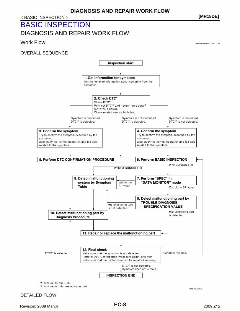
OVERALL SEQUENCE
DETAILED FLOW
JMBIA0078GB
EC-8Revision: 2009 March 2009 Z12
DIAGNOSIS AND REPAIR WORK FLOW[MR18DE]
C
D
E
F
G
H
I
J
K
L
M
A
C
N
P
O
< BASIC INSPECTION >
E
1.GET INFORMATION FOR SYMPTOM
Get the detailed information from the customer about the symptom (the condition and the environment whenthe incident/malfunction occurred) using the “Diagnostic Work Sheet”. (Refer to EC-11, "Diagnostic WorkSheet".)
>> GO TO 2.
2.CHECK DTC
1. Check DTC.2. Perform the following procedure if DTC is displayed.- Record DTC and freeze frame data. (Print them out with CONSULT-III or GST.)- Erase DTC. (Refer to “How to Erase DTC and 1st Trip DTC” in EC-85, "Diagnosis Description".)- Study the relationship between the cause detected by DTC and the symptom described by the customer.
(Symptom Table is useful. Refer to EC-460, "Symptom Table".)3. Check related service bulletins for information.Is any symptom described and is any DTC detected?Symptom is described, DTC is detected>>GO TO 3.Symptom is described, DTC is not detected>>GO TO 4.Symptom is not described, DTC is detected>>GO TO 5.
3.CONFIRM THE SYMPTOM
Try to confirm the symptom described by the customer (except MIL ON).Also study the normal operation and fail safe related to the symptom. Refer to EC-464, "Description" and EC-445, "Fail Safe".Diagnosis Work Sheet is useful to verify the incident.Verify relation between the symptom and the condition when the symptom is detected.
>> GO TO 5.
4.CONFIRM THE SYMPTOM
Try to confirm the symptom described by the customer.Also study the normal operation and fail safe related to the symptom. Refer to EC-464, "Description" and EC-445, "Fail Safe".Diagnosis Work Sheet is useful to verify the incident.Verify relation between the symptom and the condition when the symptom is detected.
>> GO TO 6.
5.PERFORM DTC CONFIRMATION PROCEDURE
Perform DTC CONFIRMATION PROCEDURE for the displayed DTC, and then make sure that DTC isdetected again.If two or more DTCs are detected, refer to EC-447, "DTC Inspection Priority Chart" and determine troublediagnosis order.NOTE:• Freeze frame data is useful if the DTC is not detected.• Perform Component Function Check if DTC CONFIRMATION PROCEDURE is not included on Service
Manual. This simplified check procedure is an effective alternative though DTC cannot be detected duringthis check.If the result of Component Function Check is NG, it is the same as the detection of DTC by DTC CONFIR-MATION PROCEDURE.
Is DTC detected?YES >> GO TO 10.NO >> Check Intermittent Incident according to EC-110, "Diagnosis Procedure".
6.PERFORM BASIC INSPECTION
Perform EC-12, "BASIC INSPECTION : Special Repair Requirement".Do you have CONSULT-III?
EC-9Revision: 2009 March 2009 Z12
[MR18DE]DIAGNOSIS AND REPAIR WORK FLOW
< BASIC INSPECTION >YES >> GO TO 7.NO >> GO TO 9.
7.PERFORM SPEC IN DATA MONITOR MODE
With CONSULT-IIIMake sure that “MAS A/F SE-B1”, “B/FUEL SCHDL” and “A/F ALPHA-B1” are within the SP value using“SPEC” of “DATA MONITOR” mode with CONSULT-III. Refer to EC-109, "Component Function Check".Are they within the SP value?YES >> GO TO 9.NO >> GO TO 8.
8.DETECT MALFUNCTIONING PART BY TROUBLE DIAGNOSIS - SPECIFICATION VALUE
Detect malfunctioning part according to EC-110, "Diagnosis Procedure".Is malfunctioning part detected?YES >> GO TO 11.NO >> GO TO 9.
9.DETECT MALFUNCTIONING SYSTEM BY SYMPTOM TABLE
Detect malfunctioning system according to EC-460, "Symptom Table" based on the confirmed symptom instep 4, and determine the trouble diagnosis order based on possible causes and symptom.
>> GO TO 10.
10.DETECT MALFUNCTIONING PART BY DIAGNOSIS PROCEDURE
Inspect according to Diagnosis Procedure of the system.NOTE:The Diagnosis Procedure in EC section described based on open circuit inspection. A short circuit inspectionis also required for the circuit check in the Diagnosis Procedure. For details, refer to “Circuit Inspection” in GI-37, "Circuit Inspection".Is malfunctioning part detected?YES >> GO TO 11.NO >> Monitor input data from related sensors or check the voltage of related ECM terminals using CON-
SULT-III. Refer to EC-416, "Reference Value".
11.REPAIR OR REPLACE THE MALFUNCTIONING PART
1. Repair or replace the malfunctioning part.2. Reconnect parts or connectors disconnected during Diagnosis Procedure again after repair and replace-
ment.3. Check DTC. If DTC is displayed, erase it. Refer to “How to Erase DTC and 1st Trip DTC” in EC-85, "Diag-
nosis Description".
>> GO TO 12.
12.FINAL CHECK
When DTC was detected in step 2, perform DTC CONFIRMATION PROCEDURE or Component FunctionCheck again, and then make sure that the malfunction have been repaired securely.When symptom was described from the customer, refer to confirmed symptom in step 3 or 4, and make surethat the symptom is not detected.Is DTC detected and does symptom remain?YES-1 >> DTC is detected: GO TO 10.YES-2 >> Symptom remains: GO TO 6.NO >> 1. Before returning the vehicle to the customer, make sure to erase unnecessary DTC in ECM
(Refer to “How to Erase DTC and 1st Trip DTC” in EC-85, "Diagnosis Description".) and TCM(Refer to TM-91, "Diagnosis Description".).
2. If the completion of SRT is needed, drive vehicle under the specific “DRIVING PATTERN” inEC-451, "How to Set SRT Code".
3. INSPECTION END
EC-10Revision: 2009 March 2009 Z12
DIAGNOSIS AND REPAIR WORK FLOW[MR18DE]
C
D
E
F
G
H
I
J
K
L
M
A
C
N
P
O
< BASIC INSPECTION >
E
Diagnostic Work Sheet INFOID:0000000004833141
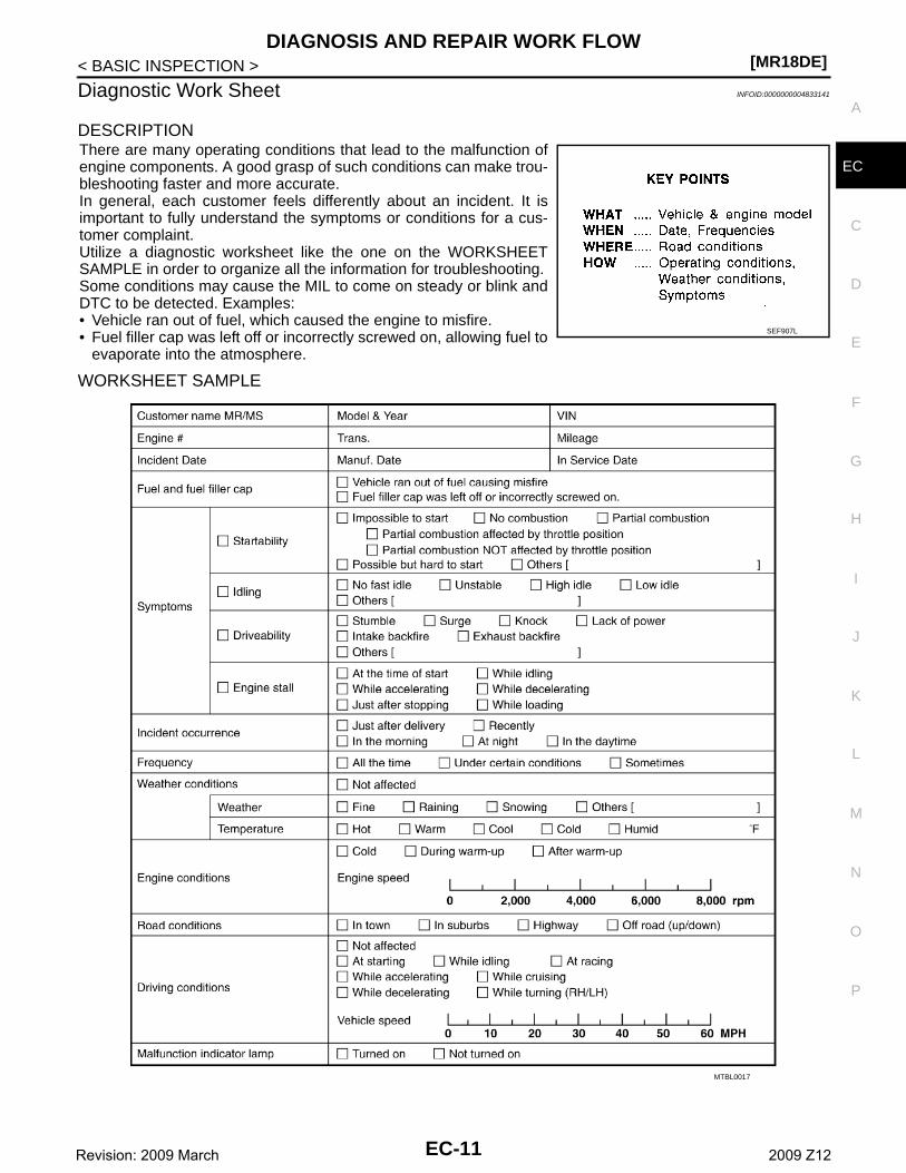
DESCRIPTIONThere are many operating conditions that lead to the malfunction ofengine components. A good grasp of such conditions can make trou-bleshooting faster and more accurate.In general, each customer feels differently about an incident. It isimportant to fully understand the symptoms or conditions for a cus-tomer complaint.Utilize a diagnostic worksheet like the one on the WORKSHEETSAMPLE in order to organize all the information for troubleshooting.Some conditions may cause the MIL to come on steady or blink andDTC to be detected. Examples:• Vehicle ran out of fuel, which caused the engine to misfire.• Fuel filler cap was left off or incorrectly screwed on, allowing fuel to
evaporate into the atmosphere.
WORKSHEET SAMPLE
SEF907L
MTBL0017
EC-11Revision: 2009 March 2009 Z12
[MR18DE]INSPECTION AND ADJUSTMENT
< BASIC INSPECTION >
INSPECTION AND ADJUSTMENTBASIC INSPECTION
BASIC INSPECTION : Special Repair Requirement INFOID:0000000004833142
1.INSPECTION START
1. Check service records for any recent repairs that may indicate a related malfunction, or a current need forscheduled maintenance.
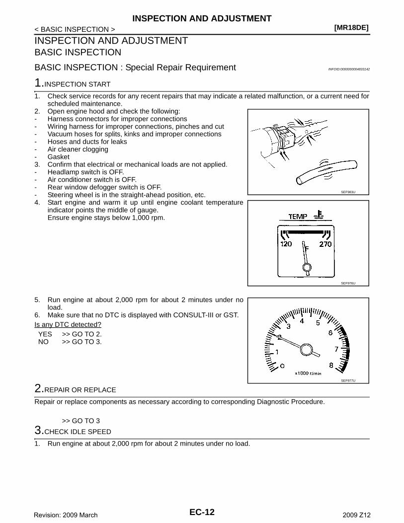
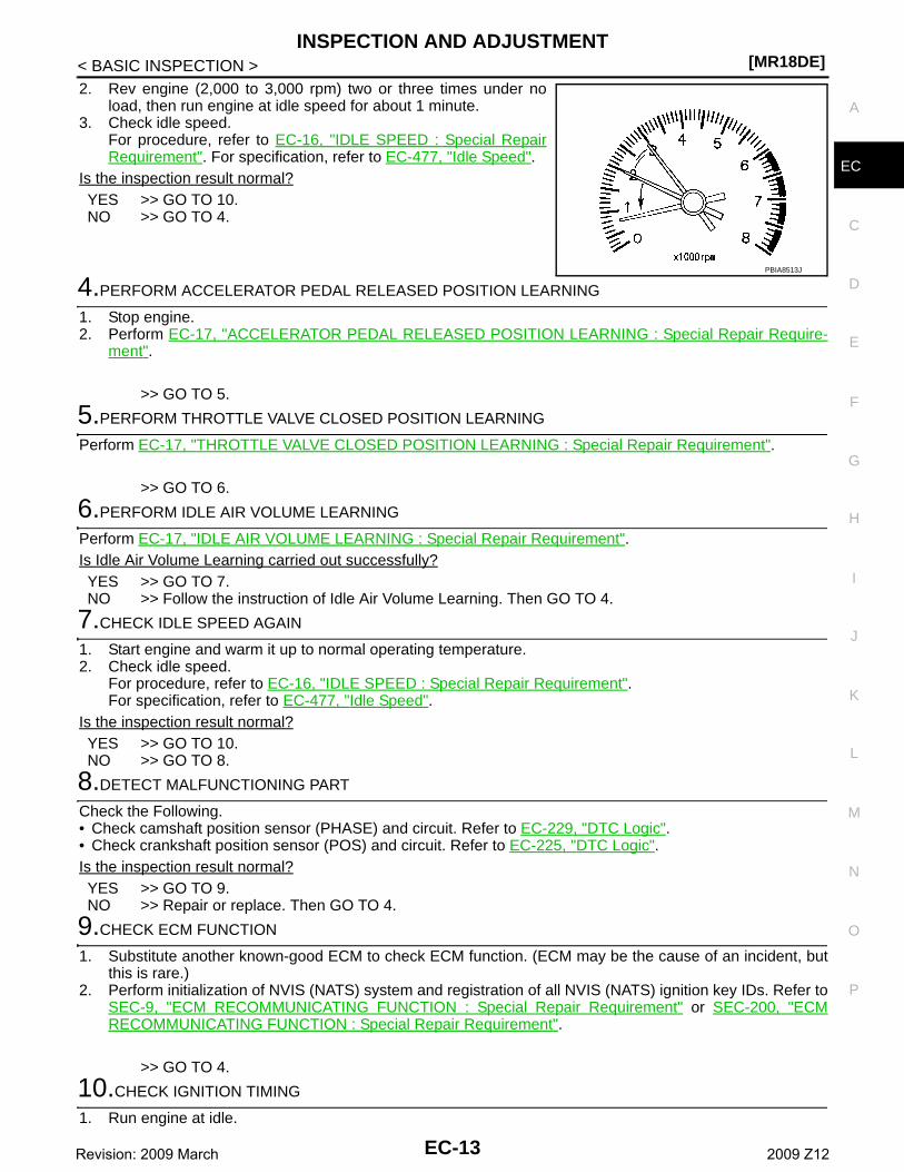
2. Open engine hood and check the following:- Harness connectors for improper connections- Wiring harness for improper connections, pinches and cut- Vacuum hoses for splits, kinks and improper connections- Hoses and ducts for leaks- Air cleaner clogging- Gasket3. Confirm that electrical or mechanical loads are not applied.- Headlamp switch is OFF.- Air conditioner switch is OFF.- Rear window defogger switch is OFF.- Steering wheel is in the straight-ahead position, etc.4. Start engine and warm it up until engine coolant temperature
indicator points the middle of gauge.Ensure engine stays below 1,000 rpm.
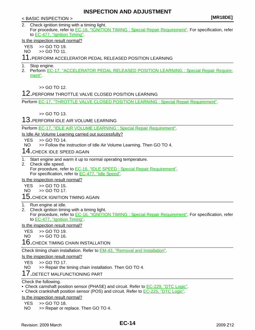
5. Run engine at about 2,000 rpm for about 2 minutes under noload.
6. Make sure that no DTC is displayed with CONSULT-III or GST.Is any DTC detected?YES >> GO TO 2.NO >> GO TO 3.
2.REPAIR OR REPLACE
Repair or replace components as necessary according to corresponding Diagnostic Procedure.
>> GO TO 3
3.CHECK IDLE SPEED
1. Run engine at about 2,000 rpm for about 2 minutes under no load.
SEF983U
SEF976U
SEF977U
EC-12Revision: 2009 March 2009 Z12
INSPECTION AND ADJUSTMENT[MR18DE]
C
D
E
F
G
H
I
J
K
L
M
A
C
N
P
O
< BASIC INSPECTION >
E
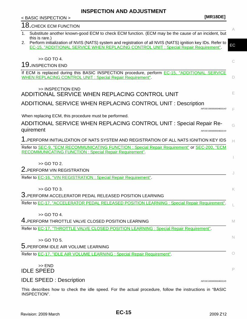
2. Rev engine (2,000 to 3,000 rpm) two or three times under noload, then run engine at idle speed for about 1 minute.
3. Check idle speed.For procedure, refer to EC-16, "IDLE SPEED : Special RepairRequirement". For specification, refer to EC-477, "Idle Speed".
Is the inspection result normal?YES >> GO TO 10.NO >> GO TO 4.
4.PERFORM ACCELERATOR PEDAL RELEASED POSITION LEARNING
1. Stop engine.2. Perform EC-17, "ACCELERATOR PEDAL RELEASED POSITION LEARNING : Special Repair Require-
ment".
>> GO TO 5.
5.PERFORM THROTTLE VALVE CLOSED POSITION LEARNING
Perform EC-17, "THROTTLE VALVE CLOSED POSITION LEARNING : Special Repair Requirement".
>> GO TO 6.
6.PERFORM IDLE AIR VOLUME LEARNING
Perform EC-17, "IDLE AIR VOLUME LEARNING : Special Repair Requirement".Is Idle Air Volume Learning carried out successfully?YES >> GO TO 7.NO >> Follow the instruction of Idle Air Volume Learning. Then GO TO 4.
7.CHECK IDLE SPEED AGAIN
1. Start engine and warm it up to normal operating temperature.2. Check idle speed.
For procedure, refer to EC-16, "IDLE SPEED : Special Repair Requirement".For specification, refer to EC-477, "Idle Speed".
Is the inspection result normal?YES >> GO TO 10.NO >> GO TO 8.
8.DETECT MALFUNCTIONING PART
Check the Following.• Check camshaft position sensor (PHASE) and circuit. Refer to EC-229, "DTC Logic".• Check crankshaft position sensor (POS) and circuit. Refer to EC-225, "DTC Logic".Is the inspection result normal?YES >> GO TO 9.NO >> Repair or replace. Then GO TO 4.
9.CHECK ECM FUNCTION
1. Substitute another known-good ECM to check ECM function. (ECM may be the cause of an incident, butthis is rare.)
2. Perform initialization of NVIS (NATS) system and registration of all NVIS (NATS) ignition key IDs. Refer toSEC-9, "ECM RECOMMUNICATING FUNCTION : Special Repair Requirement" or SEC-200, "ECMRECOMMUNICATING FUNCTION : Special Repair Requirement".
>> GO TO 4.
10.CHECK IGNITION TIMING
1. Run engine at idle.
PBIA8513J
EC-13Revision: 2009 March 2009 Z12
[MR18DE]INSPECTION AND ADJUSTMENT
< BASIC INSPECTION >2. Check ignition timing with a timing light.
For procedure, refer to EC-16, "IGNITION TIMING : Special Repair Requirement". For specification, referto EC-477, "Ignition Timing".
Is the inspection result normal?YES >> GO TO 19.NO >> GO TO 11.
11.PERFORM ACCELERATOR PEDAL RELEASED POSITION LEARNING
1. Stop engine.2. Perform EC-17, "ACCELERATOR PEDAL RELEASED POSITION LEARNING : Special Repair Require-
ment".
>> GO TO 12.
12.PERFORM THROTTLE VALVE CLOSED POSITION LEARNING
Perform EC-17, "THROTTLE VALVE CLOSED POSITION LEARNING : Special Repair Requirement".
>> GO TO 13.
13.PERFORM IDLE AIR VOLUME LEARNING
Perform EC-17, "IDLE AIR VOLUME LEARNING : Special Repair Requirement".Is Idle Air Volume Learning carried out successfully?YES >> GO TO 14.NO >> Follow the instruction of Idle Air Volume Learning. Then GO TO 4.
14.CHECK IDLE SPEED AGAIN
1. Start engine and warm it up to normal operating temperature.2. Check idle speed.
For procedure, refer to EC-16, "IDLE SPEED : Special Repair Requirement".For specification, refer to EC-477, "Idle Speed".
Is the inspection result normal?YES >> GO TO 15.NO >> GO TO 17.
15.CHECK IGNITION TIMING AGAIN
1. Run engine at idle.2. Check ignition timing with a timing light.
For procedure, refer to EC-16, "IGNITION TIMING : Special Repair Requirement". For specification, referto EC-477, "Ignition Timing".
Is the inspection result normal?YES >> GO TO 19.NO >> GO TO 16.
16.CHECK TIMING CHAIN INSTALLATION
Check timing chain installation. Refer to EM-43, "Removal and Installation".Is the inspection result normal?YES >> GO TO 17.NO >> Repair the timing chain installation. Then GO TO 4.
17.DETECT MALFUNCTIONING PART
Check the following.• Check camshaft position sensor (PHASE) and circuit. Refer to EC-229, "DTC Logic".• Check crankshaft position sensor (POS) and circuit. Refer to EC-225, "DTC Logic".Is the inspection result normal?YES >> GO TO 18.NO >> Repair or replace. Then GO TO 4.
EC-14Revision: 2009 March 2009 Z12
INSPECTION AND ADJUSTMENT[MR18DE]
C
D
E
F
G
H
I
J
K
L
M
A
C
N
P
O
< BASIC INSPECTION >
E
18.CHECK ECM FUNCTION
1. Substitute another known-good ECM to check ECM function. (ECM may be the cause of an incident, butthis is rare.)
2. Perform initialization of NVIS (NATS) system and registration of all NVIS (NATS) ignition key IDs. Refer toEC-15, "ADDITIONAL SERVICE WHEN REPLACING CONTROL UNIT : Special Repair Requirement".
>> GO TO 4.
19.INSPECTION END
If ECM is replaced during this BASIC INSPECTION procedure, perform EC-15, "ADDITIONAL SERVICEWHEN REPLACING CONTROL UNIT : Special Repair Requirement".
>> INSPECTION ENDADDITIONAL SERVICE WHEN REPLACING CONTROL UNIT
ADDITIONAL SERVICE WHEN REPLACING CONTROL UNIT : DescriptionINFOID:0000000004833143
When replacing ECM, this procedure must be performed.
ADDITIONAL SERVICE WHEN REPLACING CONTROL UNIT : Special Repair Re-quirement INFOID:0000000004833144
1.PERFORM INITIALIZATION OF NATS SYSTEM AND REGISTRATION OF ALL NATS IGNITION KEY IDS
Refer to SEC-9, "ECM RECOMMUNICATING FUNCTION : Special Repair Requirement" or SEC-200, "ECMRECOMMUNICATING FUNCTION : Special Repair Requirement".
>> GO TO 2.
2.PERFORM VIN REGISTRATION
Refer to EC-16, "VIN REGISTRATION : Special Repair Requirement".
>> GO TO 3.
3.PERFORM ACCELERATOR PEDAL RELEASED POSITION LEARNING
Refer to EC-17, "ACCELERATOR PEDAL RELEASED POSITION LEARNING : Special Repair Requirement".
>> GO TO 4.
4.PERFORM THROTTLE VALVE CLOSED POSITION LEARNING
Refer to EC-17, "THROTTLE VALVE CLOSED POSITION LEARNING : Special Repair Requirement".
>> GO TO 5.
5.PERFORM IDLE AIR VOLUME LEARNING
Refer to EC-17, "IDLE AIR VOLUME LEARNING : Special Repair Requirement".
>> ENDIDLE SPEED
IDLE SPEED : Description INFOID:0000000004833145
This describes how to check the idle speed. For the actual procedure, follow the instructions in “BASICINSPECTION”.
EC-15Revision: 2009 March 2009 Z12
[MR18DE]INSPECTION AND ADJUSTMENT
< BASIC INSPECTION >
IDLE SPEED : Special Repair Requirement INFOID:0000000004833146
1.CHECK IDLE SPEED
With CONSULT-IIICheck idle speed in “DATA MONITOR” mode with CONSULT-III.
With GSTCheck idle speed with Service $01 of GST.
>> INSPECTION ENDIGNITION TIMING
IGNITION TIMING : Description INFOID:0000000004833147
This describes how to check the ignition timing. For the actual procedure, follow the instructions in “BASICINSPECTION”.
IGNITION TIMING : Special Repair Requirement INFOID:0000000004833148
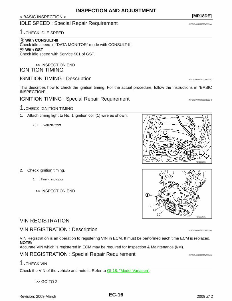
1.CHECK IGNITION TIMING
1. Attach timing light to No. 1 ignition coil (1) wire as shown.
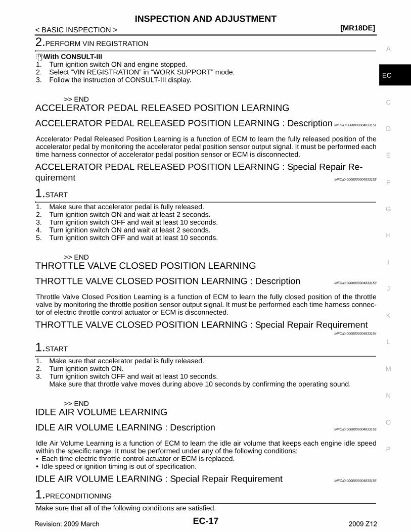
2. Check ignition timing.
>> INSPECTION END
VIN REGISTRATION
VIN REGISTRATION : Description INFOID:0000000004833149
VIN Registration is an operation to registering VIN in ECM. It must be performed each time ECM is replaced.NOTE:Accurate VIN which is registered in ECM may be required for Inspection & Maintenance (I/M).
VIN REGISTRATION : Special Repair Requirement INFOID:0000000004833150
1.CHECK VIN
Check the VIN of the vehicle and note it. Refer to GI-18, "Model Variation".
>> GO TO 2.
: Vehicle front
PBIB3320E
1 : Timing indicator
PBIB3263E
EC-16Revision: 2009 March 2009 Z12
INSPECTION AND ADJUSTMENT[MR18DE]
C
D
E
F
G
H
I
J
K
L
M
A
C
N
P
O
< BASIC INSPECTION >
E
2.PERFORM VIN REGISTRATION
With CONSULT-III1. Turn ignition switch ON and engine stopped.2. Select “VIN REGISTRATION” in “WORK SUPPORT” mode.3. Follow the instruction of CONSULT-III display.
>> ENDACCELERATOR PEDAL RELEASED POSITION LEARNING
ACCELERATOR PEDAL RELEASED POSITION LEARNING : Description INFOID:0000000004833151
Accelerator Pedal Released Position Learning is a function of ECM to learn the fully released position of theaccelerator pedal by monitoring the accelerator pedal position sensor output signal. It must be performed eachtime harness connector of accelerator pedal position sensor or ECM is disconnected.
ACCELERATOR PEDAL RELEASED POSITION LEARNING : Special Repair Re-quirement INFOID:0000000004833152
1.START
1. Make sure that accelerator pedal is fully released.2. Turn ignition switch ON and wait at least 2 seconds.3. Turn ignition switch OFF and wait at least 10 seconds.4. Turn ignition switch ON and wait at least 2 seconds.5. Turn ignition switch OFF and wait at least 10 seconds.
>> ENDTHROTTLE VALVE CLOSED POSITION LEARNING
THROTTLE VALVE CLOSED POSITION LEARNING : Description INFOID:0000000004833153
Throttle Valve Closed Position Learning is a function of ECM to learn the fully closed position of the throttlevalve by monitoring the throttle position sensor output signal. It must be performed each time harness connec-tor of electric throttle control actuator or ECM is disconnected.
THROTTLE VALVE CLOSED POSITION LEARNING : Special Repair RequirementINFOID:0000000004833154
1.START
1. Make sure that accelerator pedal is fully released.2. Turn ignition switch ON.3. Turn ignition switch OFF and wait at least 10 seconds.
Make sure that throttle valve moves during above 10 seconds by confirming the operating sound.
>> ENDIDLE AIR VOLUME LEARNING
IDLE AIR VOLUME LEARNING : Description INFOID:0000000004833155
Idle Air Volume Learning is a function of ECM to learn the idle air volume that keeps each engine idle speedwithin the specific range. It must be performed under any of the following conditions:• Each time electric throttle control actuator or ECM is replaced.• Idle speed or ignition timing is out of specification.
IDLE AIR VOLUME LEARNING : Special Repair Requirement INFOID:0000000004833156
1.PRECONDITIONING
Make sure that all of the following conditions are satisfied.
EC-17Revision: 2009 March 2009 Z12
[MR18DE]INSPECTION AND ADJUSTMENT
< BASIC INSPECTION >Learning will be cancelled if any of the following conditions are missed for even a moment.• Battery voltage: More than 12.9 V (At idle)• Engine coolant temperature: 70 - 100°C (158 - 212°F)• Selector lever: P or N (CVT), Neutral (M/T)• Electric load switch: OFF
(Air conditioner, headlamp, rear window defogger)On vehicles equipped with daytime light systems, if the parking brake is applied before the engine isstarted the headlamp will not be illuminated.
• Steering wheel: Neutral (Straight-ahead position)• Vehicle speed: Stopped• Transmission: Warmed-up- CVT models• With CONSULT-III: Drive vehicle until “FLUID TEMP SE” in “DATA MONITOR” mode of “TRANSMISSION”
system indicates less than 0.9 V.• Without CONSULT-III: Drive vehicle for 10 minutes.- M/T models• Drive vehicle for 10 minutes.Do you have CONSULT-III?YES >> GO TO 2.NO >> GO TO 3.
2.IDLE AIR VOLUME LEARNING
With CONSULT-III1. Perform Accelerator Pedal Released Position Learning. Refer to EC-17, "ACCELERATOR PEDAL
RELEASED POSITION LEARNING : Special Repair Requirement".2. Perform Throttle Valve Closed Position Learning. Refer to EC-17, "THROTTLE VALVE CLOSED POSI-
TION LEARNING : Special Repair Requirement".3. Start engine and warm it up to normal operating temperature.4. Select “IDLE AIR VOL LEARN” in “WORK SUPPORT” mode.5. Touch “START” and wait 20 seconds.Is “CMPLT” displayed on CONSULT-III screen?YES >> GO TO 4.NO >> GO TO 5.
3.IDLE AIR VOLUME LEARNING
Without CONSULT-IIINOTE:• It is better to count the time accurately with a clock.• It is impossible to switch the diagnostic mode when an accelerator pedal position sensor circuit has
a malfunction.1. Perform Accelerator Pedal Released Position Learning. Refer to EC-17, "ACCELERATOR PEDAL
RELEASED POSITION LEARNING : Special Repair Requirement".2. Perform Throttle Valve Closed Position Learning. Refer to EC-17, "THROTTLE VALVE CLOSED POSI-
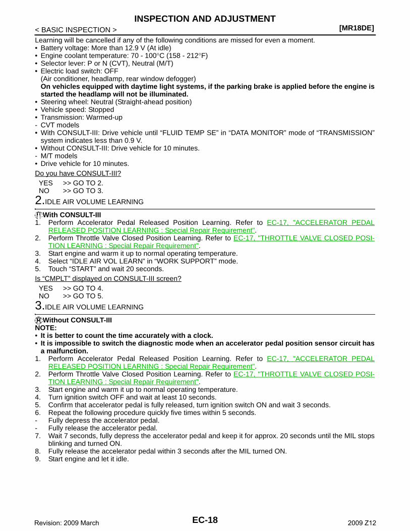
TION LEARNING : Special Repair Requirement".3. Start engine and warm it up to normal operating temperature.4. Turn ignition switch OFF and wait at least 10 seconds.5. Confirm that accelerator pedal is fully released, turn ignition switch ON and wait 3 seconds.6. Repeat the following procedure quickly five times within 5 seconds.- Fully depress the accelerator pedal.- Fully release the accelerator pedal.7. Wait 7 seconds, fully depress the accelerator pedal and keep it for approx. 20 seconds until the MIL stops
blinking and turned ON.8. Fully release the accelerator pedal within 3 seconds after the MIL turned ON.9. Start engine and let it idle.
EC-18Revision: 2009 March 2009 Z12
INSPECTION AND ADJUSTMENT[MR18DE]
C
D
E
F
G
H
I
J
K
L
M
A
C
N
P
O
< BASIC INSPECTION >
E
10. Wait 20 seconds.
>> GO TO 4.
4.CHECK IDLE SPEED AND IGNITION TIMING
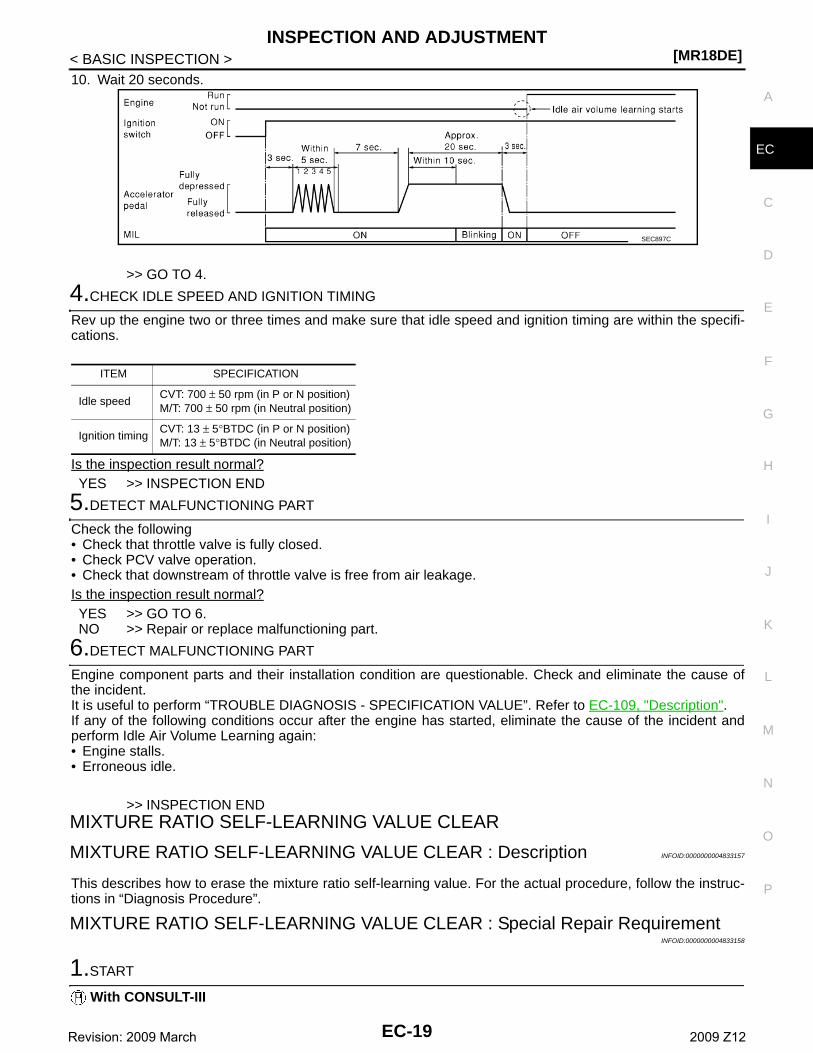
Rev up the engine two or three times and make sure that idle speed and ignition timing are within the specifi-cations.
Is the inspection result normal?YES >> INSPECTION END
5.DETECT MALFUNCTIONING PART
Check the following• Check that throttle valve is fully closed.• Check PCV valve operation.• Check that downstream of throttle valve is free from air leakage.Is the inspection result normal?YES >> GO TO 6.NO >> Repair or replace malfunctioning part.
6.DETECT MALFUNCTIONING PART
Engine component parts and their installation condition are questionable. Check and eliminate the cause ofthe incident.It is useful to perform “TROUBLE DIAGNOSIS - SPECIFICATION VALUE”. Refer to EC-109, "Description".If any of the following conditions occur after the engine has started, eliminate the cause of the incident andperform Idle Air Volume Learning again:• Engine stalls.• Erroneous idle.
>> INSPECTION ENDMIXTURE RATIO SELF-LEARNING VALUE CLEAR
MIXTURE RATIO SELF-LEARNING VALUE CLEAR : Description INFOID:0000000004833157
This describes how to erase the mixture ratio self-learning value. For the actual procedure, follow the instruc-tions in “Diagnosis Procedure”.
MIXTURE RATIO SELF-LEARNING VALUE CLEAR : Special Repair RequirementINFOID:0000000004833158
1.START
With CONSULT-III
SEC897C
ITEM SPECIFICATION
Idle speedCVT: 700 ± 50 rpm (in P or N position)M/T: 700 ± 50 rpm (in Neutral position)
Ignition timingCVT: 13 ± 5°BTDC (in P or N position)M/T: 13 ± 5°BTDC (in Neutral position)
EC-19Revision: 2009 March 2009 Z12
[MR18DE]INSPECTION AND ADJUSTMENT
< BASIC INSPECTION >1. Start engine and warm it up to normal operating temperature.2. Select “SELF-LEARNING CONT” in “WORK SUPPORT” mode with CONSULT-III.3. Clear mixture ratio self-learning value by touching “CLEAR”.
With GST1. Start engine and warm it up to normal operating temperature.2. Turn ignition switch OFF.3. Disconnect mass air flow sensor harness connector.4. Restart engine and let it idle for at least 5 seconds.5. Stop engine and reconnect mass air flow sensor harness connector.6. Select Service $03 with GST. Make sure DTC P0102 is detected.7. Select Service $04 with GST to erase the DTC P0102.
>> END
EC-20Revision: 2009 March 2009 Z12
ENGINE CONTROL SYSTEM[MR18DE]
C
D
E
F
G
H
I
J
K
L
M
A
C
N
P
O
< SYSTEM DESCRIPTION >
E
SYSTEM DESCRIPTIONENGINE CONTROL SYSTEM
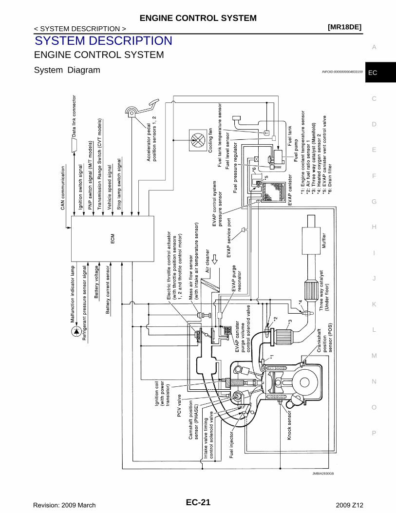
System Diagram INFOID:0000000004833159
JMBIA2930GB
EC-21Revision: 2009 March 2009 Z12
[MR18DE]ENGINE CONTROL SYSTEM
< SYSTEM DESCRIPTION >
System Description INFOID:0000000004833160
ECM performs various controls such as fuel injection control and ignition timing control.
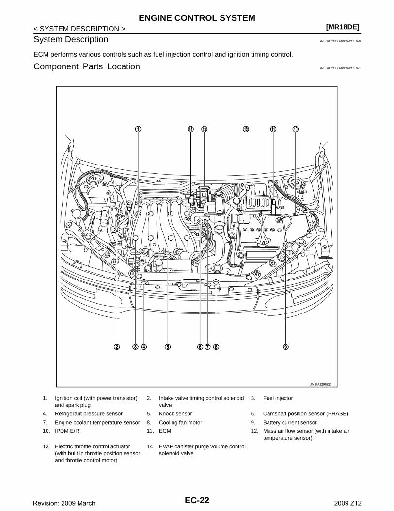
Component Parts Location INFOID:0000000004833161
1. Ignition coil (with power transistor) and spark plug
2. Intake valve timing control solenoid valve
3. Fuel injector
4. Refrigerant pressure sensor 5. Knock sensor 6. Camshaft position sensor (PHASE)
7. Engine coolant temperature sensor 8. Cooling fan motor 9. Battery current sensor
10. IPDM E/R 11. ECM 12. Mass air flow sensor (with intake air temperature sensor)
13. Electric throttle control actuator(with built in throttle position sensor and throttle control motor)
14. EVAP canister purge volume control solenoid valve
JMBIA2296ZZ
EC-22Revision: 2009 March 2009 Z12

ENGINE CONTROL SYSTEM[MR18DE]
C
D
E
F
G
H
I
J
K
L
M
A
C
N
P
O
< SYSTEM DESCRIPTION >
E
1. ECM 2. IPDM E/R 3. Fuel pump fuse (15 A)
Vehicle front
1. Electric throttle control actuator(with built-in position sensor, throttle control motor)
2. Throttle valve
Vehicle front
1. Battery current sensor 2. Mass air flow sensor(with Intake air temperature sensor)
Vehicle front
JMBIA2297ZZ
JMBIA2298ZZ
JMBIA2299ZZ
JMBIA2300ZZ
EC-23Revision: 2009 March 2009 Z12

[MR18DE]ENGINE CONTROL SYSTEM
< SYSTEM DESCRIPTION >
1. Camshaft position sensor (PHASE) 2. Engine coolant temperature sensor
Vehicle front
1. Air fuel ratio (A/F) sensor 1 2. Three way catalyst (Manifold) 3. Heated oxygen sensor 2
4. Three way catalyst (under floor) 5. Muffler
Vehicle front
1. Air fuel ratio (A/F) sensor 1 harness connector
2. Air fuel ratio (A/F) sensor 1 3. Heated oxygen sensor 2
4. Heated oxygen sensor 2 harness connector
Vehicle front
1. PCV valve 2. Ignition coil (with power transistor) and spark plug
3. Fuel injector
Vehicle front
JMBIA2192ZZ
JMBIA2301ZZ
JMBIA2302ZZ
EC-24Revision: 2009 March 2009 Z12
ENGINE CONTROL SYSTEM[MR18DE]
C
D
E
F
G
H
I
J
K
L
M
A
C
N
P
O
< SYSTEM DESCRIPTION >
E
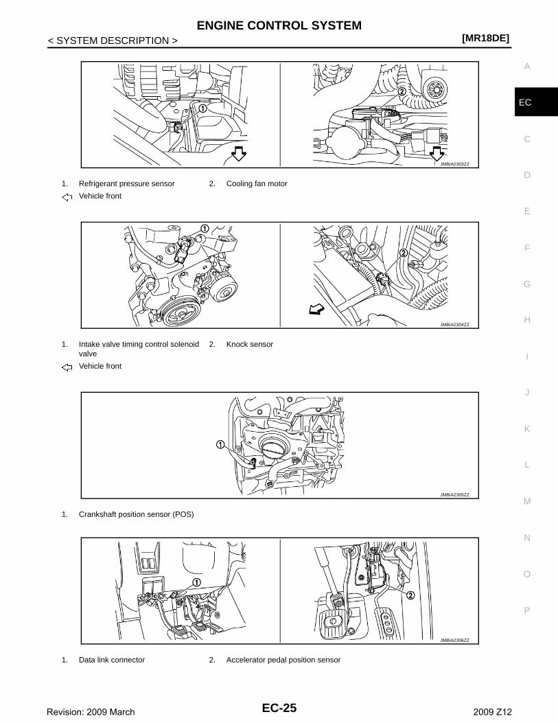
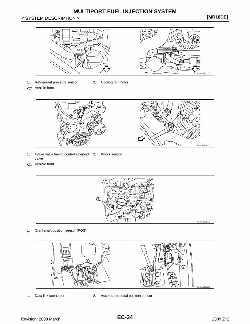
1. Refrigerant pressure sensor 2. Cooling fan motor
Vehicle front
1. Intake valve timing control solenoid valve
2. Knock sensor
Vehicle front
1. Crankshaft position sensor (POS)
1. Data link connector 2. Accelerator pedal position sensor
JMBIA2303ZZ
JMBIA2304ZZ
JMBIA2305ZZ
JMBIA2306ZZ
EC-25Revision: 2009 March 2009 Z12
[MR18DE]ENGINE CONTROL SYSTEM
< SYSTEM DESCRIPTION >
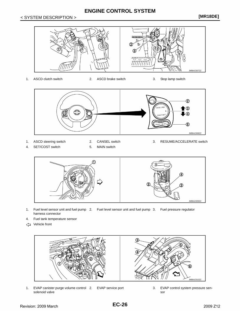
1. ASCD clutch switch 2. ASCD brake switch 3. Stop lamp switch
1. ASCD steering switch 2. CANSEL switch 3. RESUME/ACCELERATE switch
4. SET/COST switch 5. MAIN switch
1. Fuel level sensor unit and fuel pump harness connector
2. Fuel level sensor unit and fuel pump 3. Fuel pressure regulator
4. Fuel tank temperature sensor
Vehicle front
1. EVAP canister purge volume control solenoid valve
2. EVAP service port 3. EVAP control system pressure sen-sor
JMBIA2307ZZ
JMBIA2308ZZ
JMBIA2309ZZ
JMBIA2310ZZ
EC-26Revision: 2009 March 2009 Z12
ENGINE CONTROL SYSTEM[MR18DE]
C
D
E
F
G
H
I
J
K
L
M
A
C
N
P
O
< SYSTEM DESCRIPTION >
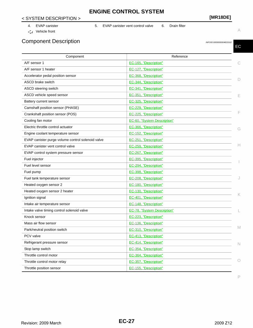
EComponent Description INFOID:0000000004833162
4. EVAP canister 5. EVAP canister vent control valve 6. Drain filter
Vehicle front
Component Reference
A/F sensor 1 EC-165, "Description"
A/F sensor 1 heater EC-127, "Description"
Accelerator pedal position sensor EC-368, "Description"
ASCD brake switch EC-344, "Description"
ASCD steering switch EC-341, "Description"
ASCD vehicle speed sensor EC-351, "Description"
Battery current sensor EC-325, "Description"
Camshaft position sensor (PHASE) EC-229, "Description"
Crankshaft position sensor (POS) EC-225, "Description"
Cooling fan motor EC-60, "System Description"
Electric throttle control actuator EC-366, "Description"
Engine coolant temperature sensor EC-152, "Description"
EVAP canister purge volume control solenoid valve EC-251, "Description"
EVAP canister vent control valve EC-259, "Description"
EVAP control system pressure sensor EC-267, "Description"
Fuel injector EC-395, "Description"
Fuel level sensor EC-294, "Description"
Fuel pump EC-398, "Description"
Fuel tank temperature sensor EC-208, "Description"
Heated oxygen sensor 2 EC-180, "Description"
Heated oxygen sensor 2 heater EC-130, "Description"
Ignition signal EC-401, "Description"
Intake air temperature sensor EC-148, "Description"
Intake valve timing control solenoid valve EC-78, "System Description"
Knock sensor EC-223, "Description"
Mass air flow sensor EC-136, "Description"
Park/neutral position switch EC-310, "Description"
PCV valve EC-413, "Description"
Refrigerant pressure sensor EC-414, "Description"
Stop lamp switch EC-354, "Description"
Throttle control motor EC-364, "Description"
Throttle control motor relay EC-357, "Description"
Throttle position sensor EC-155, "Description"
EC-27Revision: 2009 March 2009 Z12
[MR18DE]MULTIPORT FUEL INJECTION SYSTEM
< SYSTEM DESCRIPTION >
MULTIPORT FUEL INJECTION SYSTEM
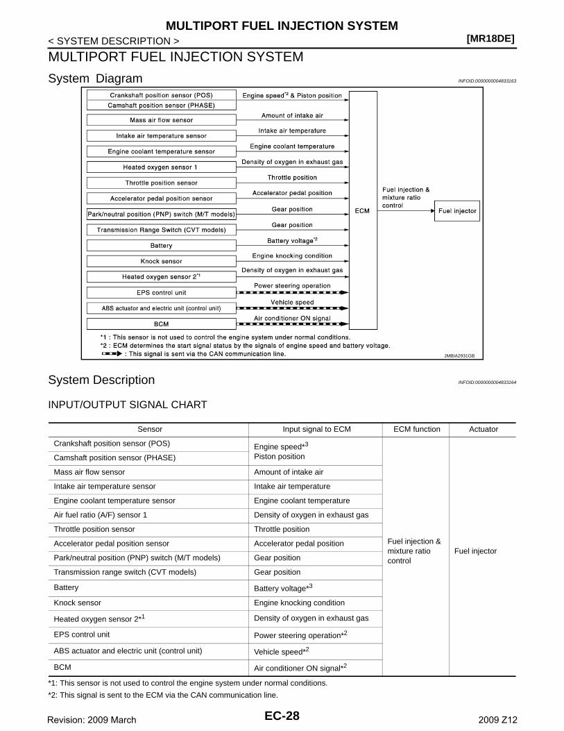
System Diagram INFOID:0000000004833163
System Description INFOID:0000000004833164
INPUT/OUTPUT SIGNAL CHART
*1: This sensor is not used to control the engine system under normal conditions.
*2: This signal is sent to the ECM via the CAN communication line.
JMBIA2931GB
Sensor Input signal to ECM ECM function Actuator
Crankshaft position sensor (POS) Engine speed*3
Piston position
Fuel injection & mixture ratio control
Fuel injector
Camshaft position sensor (PHASE)
Mass air flow sensor Amount of intake air
Intake air temperature sensor Intake air temperature
Engine coolant temperature sensor Engine coolant temperature
Air fuel ratio (A/F) sensor 1 Density of oxygen in exhaust gas
Throttle position sensor Throttle position
Accelerator pedal position sensor Accelerator pedal position
Park/neutral position (PNP) switch (M/T models) Gear position
Transmission range switch (CVT models) Gear position
Battery Battery voltage*3
Knock sensor Engine knocking condition
Heated oxygen sensor 2*1 Density of oxygen in exhaust gas
EPS control unit Power steering operation*2
ABS actuator and electric unit (control unit) Vehicle speed*2
BCM Air conditioner ON signal*2
EC-28Revision: 2009 March 2009 Z12
MULTIPORT FUEL INJECTION SYSTEM[MR18DE]
C
D
E
F
G
H
I
J
K
L
M
A
C
N
P
O
< SYSTEM DESCRIPTION >
E
*3: ECM determines the start signal status by the signals of engine speed and battery voltage.
SYSTEM DESCRIPTIONThe amount of fuel injected from the fuel injector is determined by the ECM. The ECM controls the length oftime the valve remains open (injection pulse duration). The amount of fuel injected is a program value in theECM memory. The program value is preset by engine operating conditions. These conditions are determinedby input signals (for engine speed and intake air) from the crankshaft position sensor (POS), camshaft positionsensor (PHASE) and the mass air flow sensor.
VARIOUS FUEL INJECTION INCREASE/DECREASE COMPENSATIONIn addition, the amount of fuel injected is compensated to improve engine performance under various operat-ing conditions as listed below.
<Fuel increase>• During warm-up• When starting the engine• During acceleration• Hot-engine operation• When selector lever is changed from N to D (CVT models)• High-load, high-speed operation
<Fuel decrease>• During deceleration• During high engine speed operation
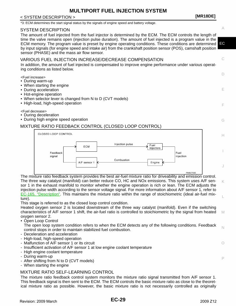
MIXTURE RATIO FEEDBACK CONTROL (CLOSED LOOP CONTROL)
The mixture ratio feedback system provides the best air-fuel mixture ratio for driveability and emission control.The three way catalyst (manifold) can better reduce CO, HC and NOx emissions. This system uses A/F sen-sor 1 in the exhaust manifold to monitor whether the engine operation is rich or lean. The ECM adjusts theinjection pulse width according to the sensor voltage signal. For more information about A/F sensor 1, refer toEC-165, "Description". This maintains the mixture ratio within the range of stoichiometric (ideal air-fuel mix-ture).This stage is referred to as the closed loop control condition.Heated oxygen sensor 2 is located downstream of the three way catalyst (manifold). Even if the switchingcharacteristics of A/F sensor 1 shift, the air-fuel ratio is controlled to stoichiometric by the signal from heatedoxygen sensor 2.• Open Loop Control
The open loop system condition refers to when the ECM detects any of the following conditions. Feedbackcontrol stops in order to maintain stabilized fuel combustion.
- Deceleration and acceleration- High-load, high-speed operation- Malfunction of A/F sensor 1 or its circuit- Insufficient activation of A/F sensor 1 at low engine coolant temperature- High engine coolant temperature- During warm-up- After shifting from N to D (CVT models)- When starting the engine
MIXTURE RATIO SELF-LEARNING CONTROLThe mixture ratio feedback control system monitors the mixture ratio signal transmitted from A/F sensor 1.This feedback signal is then sent to the ECM. The ECM controls the basic mixture ratio as close to the theoret-ical mixture ratio as possible. However, the basic mixture ratio is not necessarily controlled as originally
PBIB2793E
EC-29Revision: 2009 March 2009 Z12
[MR18DE]MULTIPORT FUEL INJECTION SYSTEM
< SYSTEM DESCRIPTION >designed. Both manufacturing differences (i.e., mass air flow sensor hot wire) and characteristic changes dur-ing operation (i.e., fuel injector clogging) directly affect mixture ratio.Accordingly, the difference between the basic and theoretical mixture ratios is monitored in this system. This isthen computed in terms of “injection pulse duration” to automatically compensate for the difference betweenthe two ratios.“Fuel trim” refers to the feedback compensation value compared against the basic injection duration. Fuel trimincludes short-term fuel trim and long-term fuel trim.“Short-term fuel trim” is the short-term fuel compensation used to maintain the mixture ratio at its theoreticalvalue. The signal from A/F sensor 1 indicates whether the mixture ratio is RICH or LEAN compared to the the-oretical value. The signal then triggers a reduction in fuel volume if the mixture ratio is rich, and an increase infuel volume if it is lean.“Long-term fuel trim” is overall fuel compensation carried out over time to compensate for continual deviationof the short-term fuel trim from the central value. Continual deviation will occur due to individual engine differ-ences, wear over time and changes in the usage environment.
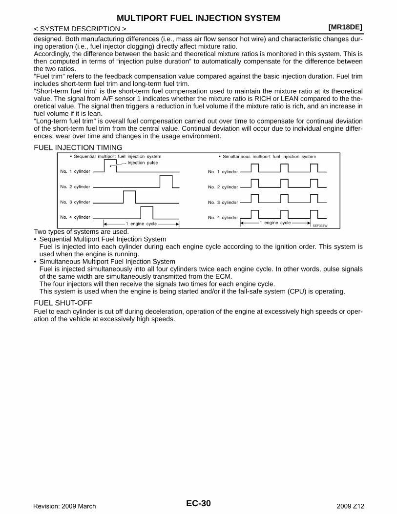
FUEL INJECTION TIMING
Two types of systems are used.• Sequential Multiport Fuel Injection System
Fuel is injected into each cylinder during each engine cycle according to the ignition order. This system isused when the engine is running.
• Simultaneous Multiport Fuel Injection SystemFuel is injected simultaneously into all four cylinders twice each engine cycle. In other words, pulse signalsof the same width are simultaneously transmitted from the ECM.The four injectors will then receive the signals two times for each engine cycle.This system is used when the engine is being started and/or if the fail-safe system (CPU) is operating.
FUEL SHUT-OFFFuel to each cylinder is cut off during deceleration, operation of the engine at excessively high speeds or oper-ation of the vehicle at excessively high speeds.
SEF337W
EC-30Revision: 2009 March 2009 Z12

MULTIPORT FUEL INJECTION SYSTEM[MR18DE]
C
D
E
F
G
H
I
J
K
L
M
A
C
N
P
O
< SYSTEM DESCRIPTION >
E
Component Parts Location INFOID:0000000004833165
1. Ignition coil (with power transistor) and spark plug
2. Intake valve timing control solenoid valve
3. Fuel injector
4. Refrigerant pressure sensor 5. Knock sensor 6. Camshaft position sensor (PHASE)
7. Engine coolant temperature sensor 8. Cooling fan motor 9. Battery current sensor
10. IPDM E/R 11. ECM 12. Mass air flow sensor (with intake air temperature sensor)
13. Electric throttle control actuator(with built in throttle position sensor and throttle control motor)
14. EVAP canister purge volume control solenoid valve
JMBIA2296ZZ
EC-31Revision: 2009 March 2009 Z12
[MR18DE]MULTIPORT FUEL INJECTION SYSTEM
< SYSTEM DESCRIPTION >
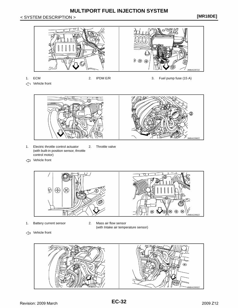
1. ECM 2. IPDM E/R 3. Fuel pump fuse (15 A)
Vehicle front
1. Electric throttle control actuator(with built-in position sensor, throttle control motor)
2. Throttle valve
Vehicle front
1. Battery current sensor 2. Mass air flow sensor(with Intake air temperature sensor)
Vehicle front
JMBIA2297ZZ
JMBIA2298ZZ
JMBIA2299ZZ
JMBIA2300ZZ
EC-32Revision: 2009 March 2009 Z12
MULTIPORT FUEL INJECTION SYSTEM[MR18DE]
C
D
E
F
G
H
I
J
K
L
M
A
C
N
P
O
< SYSTEM DESCRIPTION >
E
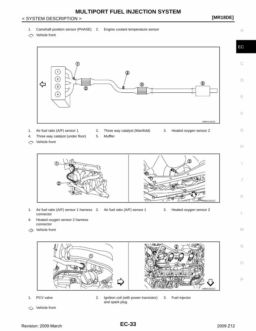
1. Camshaft position sensor (PHASE) 2. Engine coolant temperature sensor
Vehicle front
1. Air fuel ratio (A/F) sensor 1 2. Three way catalyst (Manifold) 3. Heated oxygen sensor 2
4. Three way catalyst (under floor) 5. Muffler
Vehicle front
1. Air fuel ratio (A/F) sensor 1 harness connector
2. Air fuel ratio (A/F) sensor 1 3. Heated oxygen sensor 2
4. Heated oxygen sensor 2 harness connector
Vehicle front
1. PCV valve 2. Ignition coil (with power transistor) and spark plug
3. Fuel injector
Vehicle front
JMBIA2192ZZ
JMBIA2301ZZ
JMBIA2302ZZ
EC-33Revision: 2009 March 2009 Z12
[MR18DE]MULTIPORT FUEL INJECTION SYSTEM
< SYSTEM DESCRIPTION >
1. Refrigerant pressure sensor 2. Cooling fan motor
Vehicle front
1. Intake valve timing control solenoid valve
2. Knock sensor
Vehicle front
1. Crankshaft position sensor (POS)
1. Data link connector 2. Accelerator pedal position sensor
JMBIA2303ZZ
JMBIA2304ZZ
JMBIA2305ZZ
JMBIA2306ZZ
EC-34Revision: 2009 March 2009 Z12

MULTIPORT FUEL INJECTION SYSTEM[MR18DE]
C
D
E
F
G
H
I
J
K
L
M
A
C
N
P
O
< SYSTEM DESCRIPTION >
E
1. ASCD clutch switch 2. ASCD brake switch 3. Stop lamp switch
1. ASCD steering switch 2. CANSEL switch 3. RESUME/ACCELERATE switch
4. SET/COST switch 5. MAIN switch
1. Fuel level sensor unit and fuel pump harness connector
2. Fuel level sensor unit and fuel pump 3. Fuel pressure regulator
4. Fuel tank temperature sensor
Vehicle front
1. EVAP canister purge volume control solenoid valve
2. EVAP service port 3. EVAP control system pressure sen-sor
JMBIA2307ZZ
JMBIA2308ZZ
JMBIA2309ZZ
JMBIA2310ZZ
EC-35Revision: 2009 March 2009 Z12
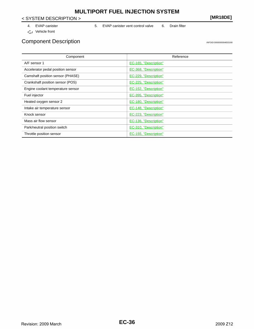
[MR18DE]MULTIPORT FUEL INJECTION SYSTEM
< SYSTEM DESCRIPTION >
Component Description INFOID:0000000004833166
4. EVAP canister 5. EVAP canister vent control valve 6. Drain filter
Vehicle front
Component Reference
A/F sensor 1 EC-165, "Description"
Accelerator pedal position sensor EC-368, "Description"
Camshaft position sensor (PHASE) EC-229, "Description"
Crankshaft position sensor (POS) EC-225, "Description"
Engine coolant temperature sensor EC-152, "Description"
Fuel injector EC-395, "Description"
Heated oxygen sensor 2 EC-180, "Description"
Intake air temperature sensor EC-148, "Description"
Knock sensor EC-223, "Description"
Mass air flow sensor EC-136, "Description"
Park/neutral position switch EC-310, "Description"
Throttle position sensor EC-155, "Description"
EC-36Revision: 2009 March 2009 Z12
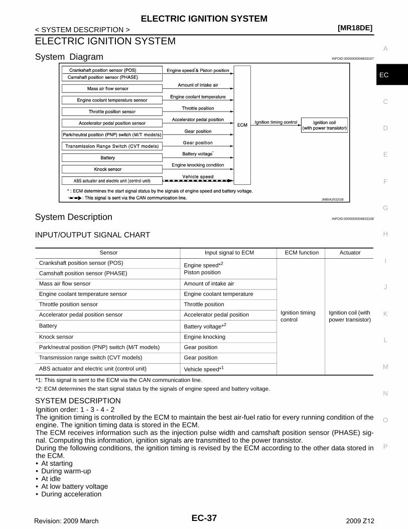
ELECTRIC IGNITION SYSTEM[MR18DE]
C
D
E
F
G
H
I
J
K
L
M
A
C
N
P
O
< SYSTEM DESCRIPTION >
E
ELECTRIC IGNITION SYSTEM
System Diagram INFOID:0000000004833167
System Description INFOID:0000000004833168
INPUT/OUTPUT SIGNAL CHART
*1: This signal is sent to the ECM via the CAN communication line.
*2: ECM determines the start signal status by the signals of engine speed and battery voltage.
SYSTEM DESCRIPTIONIgnition order: 1 - 3 - 4 - 2 The ignition timing is controlled by the ECM to maintain the best air-fuel ratio for every running condition of theengine. The ignition timing data is stored in the ECM.The ECM receives information such as the injection pulse width and camshaft position sensor (PHASE) sig-nal. Computing this information, ignition signals are transmitted to the power transistor.During the following conditions, the ignition timing is revised by the ECM according to the other data stored inthe ECM.• At starting• During warm-up• At idle• At low battery voltage• During acceleration
JMBIA2932GB
Sensor Input signal to ECM ECM function Actuator
Crankshaft position sensor (POS) Engine speed*2
Piston position
Ignition timing control
Ignition coil (with power transistor)
Camshaft position sensor (PHASE)
Mass air flow sensor Amount of intake air
Engine coolant temperature sensor Engine coolant temperature
Throttle position sensor Throttle position
Accelerator pedal position sensor Accelerator pedal position
Battery Battery voltage*2
Knock sensor Engine knocking
Park/neutral position (PNP) switch (M/T models) Gear position
Transmission range switch (CVT models) Gear position
ABS actuator and electric unit (control unit) Vehicle speed*1
EC-37Revision: 2009 March 2009 Z12
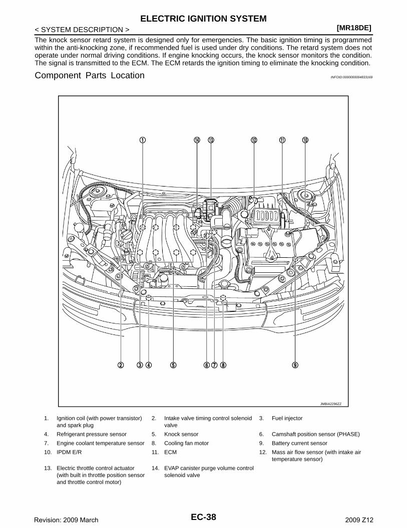
[MR18DE]ELECTRIC IGNITION SYSTEM
< SYSTEM DESCRIPTION >The knock sensor retard system is designed only for emergencies. The basic ignition timing is programmedwithin the anti-knocking zone, if recommended fuel is used under dry conditions. The retard system does notoperate under normal driving conditions. If engine knocking occurs, the knock sensor monitors the condition.The signal is transmitted to the ECM. The ECM retards the ignition timing to eliminate the knocking condition.
Component Parts Location INFOID:0000000004833169
1. Ignition coil (with power transistor) and spark plug
2. Intake valve timing control solenoid valve
3. Fuel injector
4. Refrigerant pressure sensor 5. Knock sensor 6. Camshaft position sensor (PHASE)
7. Engine coolant temperature sensor 8. Cooling fan motor 9. Battery current sensor
10. IPDM E/R 11. ECM 12. Mass air flow sensor (with intake air temperature sensor)
13. Electric throttle control actuator(with built in throttle position sensor and throttle control motor)
14. EVAP canister purge volume control solenoid valve
JMBIA2296ZZ
EC-38Revision: 2009 March 2009 Z12

ELECTRIC IGNITION SYSTEM[MR18DE]
C
D
E
F
G
H
I
J
K
L
M
A
C
N
P
O
< SYSTEM DESCRIPTION >
E
1. ECM 2. IPDM E/R 3. Fuel pump fuse (15 A)
Vehicle front
1. Electric throttle control actuator(with built-in position sensor, throttle control motor)
2. Throttle valve
Vehicle front
1. Battery current sensor 2. Mass air flow sensor(with Intake air temperature sensor)
Vehicle front
JMBIA2297ZZ
JMBIA2298ZZ
JMBIA2299ZZ
JMBIA2300ZZ
EC-39Revision: 2009 March 2009 Z12

[MR18DE]ELECTRIC IGNITION SYSTEM
< SYSTEM DESCRIPTION >
1. Camshaft position sensor (PHASE) 2. Engine coolant temperature sensor
Vehicle front
1. Air fuel ratio (A/F) sensor 1 2. Three way catalyst (Manifold) 3. Heated oxygen sensor 2
4. Three way catalyst (under floor) 5. Muffler
Vehicle front
1. Air fuel ratio (A/F) sensor 1 harness connector
2. Air fuel ratio (A/F) sensor 1 3. Heated oxygen sensor 2
4. Heated oxygen sensor 2 harness connector
Vehicle front
1. PCV valve 2. Ignition coil (with power transistor) and spark plug
3. Fuel injector
Vehicle front
JMBIA2192ZZ
JMBIA2301ZZ
JMBIA2302ZZ
EC-40Revision: 2009 March 2009 Z12

ELECTRIC IGNITION SYSTEM[MR18DE]
C
D
E
F
G
H
I
J
K
L
M
A
C
N
P
O
< SYSTEM DESCRIPTION >
E
1. Refrigerant pressure sensor 2. Cooling fan motor
Vehicle front
1. Intake valve timing control solenoid valve
2. Knock sensor
Vehicle front
1. Crankshaft position sensor (POS)
1. Data link connector 2. Accelerator pedal position sensor
JMBIA2303ZZ
JMBIA2304ZZ
JMBIA2305ZZ
JMBIA2306ZZ
EC-41Revision: 2009 March 2009 Z12
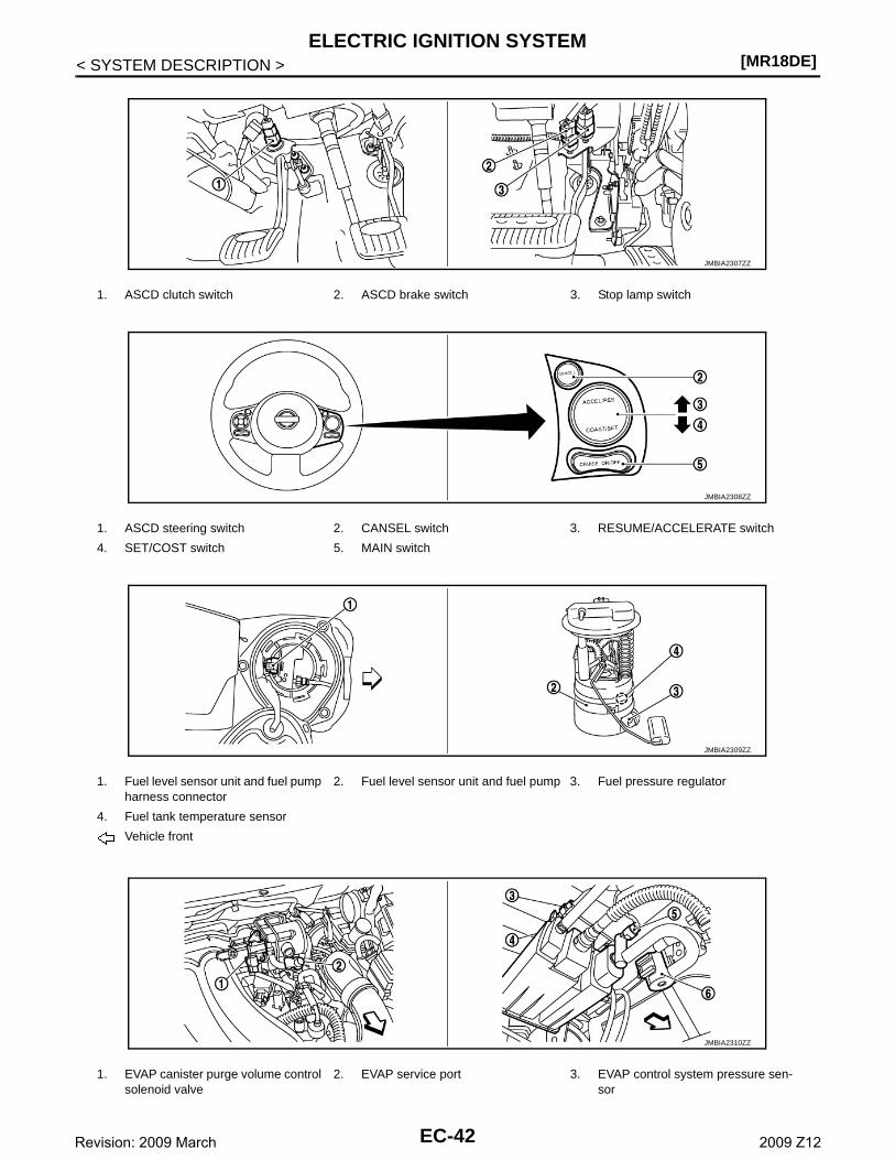
[MR18DE]ELECTRIC IGNITION SYSTEM
< SYSTEM DESCRIPTION >
1. ASCD clutch switch 2. ASCD brake switch 3. Stop lamp switch
1. ASCD steering switch 2. CANSEL switch 3. RESUME/ACCELERATE switch
4. SET/COST switch 5. MAIN switch
1. Fuel level sensor unit and fuel pump harness connector
2. Fuel level sensor unit and fuel pump 3. Fuel pressure regulator
4. Fuel tank temperature sensor
Vehicle front
1. EVAP canister purge volume control solenoid valve
2. EVAP service port 3. EVAP control system pressure sen-sor
JMBIA2307ZZ
JMBIA2308ZZ
JMBIA2309ZZ
JMBIA2310ZZ
EC-42Revision: 2009 March 2009 Z12
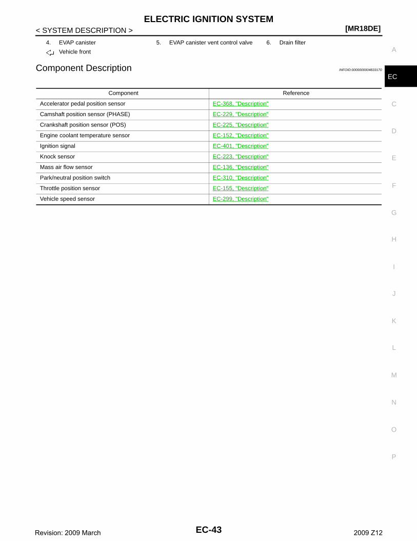
ELECTRIC IGNITION SYSTEM[MR18DE]
C
D
E
F
G
H
I
J
K
L
M
A
C
N
P
O
< SYSTEM DESCRIPTION >
EComponent Description INFOID:0000000004833170
4. EVAP canister 5. EVAP canister vent control valve 6. Drain filter
Vehicle front
Component Reference
Accelerator pedal position sensor EC-368, "Description"
Camshaft position sensor (PHASE) EC-229, "Description"
Crankshaft position sensor (POS) EC-225, "Description"
Engine coolant temperature sensor EC-152, "Description"
Ignition signal EC-401, "Description"
Knock sensor EC-223, "Description"
Mass air flow sensor EC-136, "Description"
Park/neutral position switch EC-310, "Description"
Throttle position sensor EC-155, "Description"
Vehicle speed sensor EC-299, "Description"
EC-43Revision: 2009 March 2009 Z12
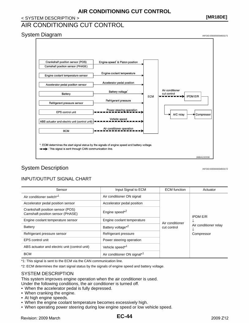
[MR18DE]AIR CONDITIONING CUT CONTROL
< SYSTEM DESCRIPTION >
AIR CONDITIONING CUT CONTROL
System Diagram INFOID:0000000004833171
System Description INFOID:0000000004833172
INPUT/OUTPUT SIGNAL CHART
*1: This signal is sent to the ECM via the CAN communication line.
*2: ECM determines the start signal status by the signals of engine speed and battery voltage.
SYSTEM DESCRIPTIONThis system improves engine operation when the air conditioner is used.Under the following conditions, the air conditioner is turned off.• When the accelerator pedal is fully depressed.• When cranking the engine.• At high engine speeds.• When the engine coolant temperature becomes excessively high.• When operating power steering during low engine speed or low vehicle speed.
JMBIA1322GB
Sensor Input Signal to ECM ECM function Actuator
Air conditioner switch*1 Air conditioner ON signal
Air conditioner cut control
IPDM E/R↓Air conditioner relay↓Compressor
Accelerator pedal position sensor Accelerator pedal position
Crankshaft position sensor (POS)Camshaft position sensor (PHASE) Engine speed*2
Engine coolant temperature sensor Engine coolant temperature
Battery Battery voltage*2
Refrigerant pressure sensor Refrigerant pressure
EPS control unit Power steering operation
ABS actuator and electric unit (control unit) Vehicle speed*1
BCM Air conditioner ON signal*1
EC-44Revision: 2009 March 2009 Z12
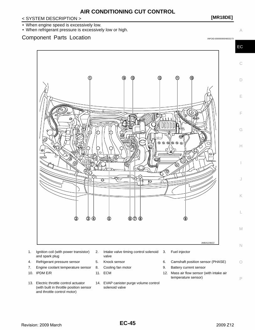
AIR CONDITIONING CUT CONTROL[MR18DE]
C
D
E
F
G
H
I
J
K
L
M
A
C
N
P
O
< SYSTEM DESCRIPTION >
E
• When engine speed is excessively low.• When refrigerant pressure is excessively low or high.
Component Parts Location INFOID:0000000004833173
1. Ignition coil (with power transistor) and spark plug
2. Intake valve timing control solenoid valve
3. Fuel injector
4. Refrigerant pressure sensor 5. Knock sensor 6. Camshaft position sensor (PHASE)
7. Engine coolant temperature sensor 8. Cooling fan motor 9. Battery current sensor
10. IPDM E/R 11. ECM 12. Mass air flow sensor (with intake air temperature sensor)
13. Electric throttle control actuator(with built in throttle position sensor and throttle control motor)
14. EVAP canister purge volume control solenoid valve
JMBIA2296ZZ
EC-45Revision: 2009 March 2009 Z12
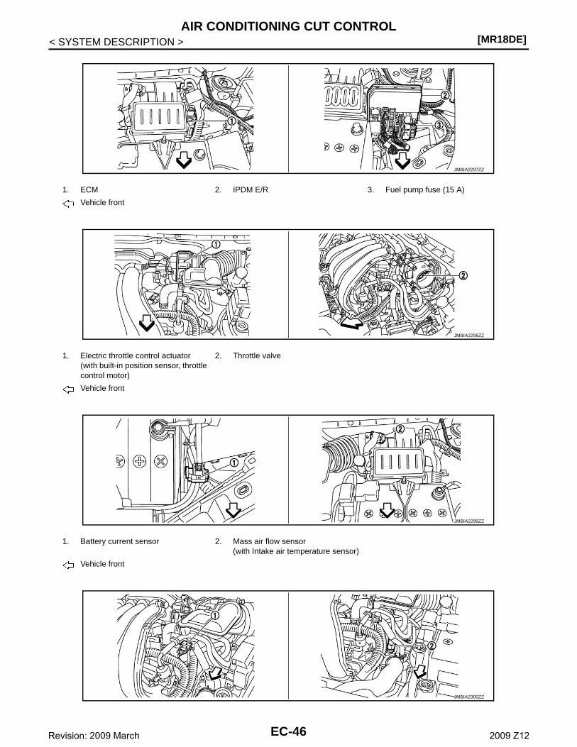
[MR18DE]AIR CONDITIONING CUT CONTROL
< SYSTEM DESCRIPTION >
1. ECM 2. IPDM E/R 3. Fuel pump fuse (15 A)
Vehicle front
1. Electric throttle control actuator(with built-in position sensor, throttle control motor)
2. Throttle valve
Vehicle front
1. Battery current sensor 2. Mass air flow sensor(with Intake air temperature sensor)
Vehicle front
JMBIA2297ZZ
JMBIA2298ZZ
JMBIA2299ZZ
JMBIA2300ZZ
EC-46Revision: 2009 March 2009 Z12

AIR CONDITIONING CUT CONTROL[MR18DE]
C
D
E
F
G
H
I
J
K
L
M
A
C
N
P
O
< SYSTEM DESCRIPTION >
E
1. Camshaft position sensor (PHASE) 2. Engine coolant temperature sensor
Vehicle front
1. Air fuel ratio (A/F) sensor 1 2. Three way catalyst (Manifold) 3. Heated oxygen sensor 2
4. Three way catalyst (under floor) 5. Muffler
Vehicle front
1. Air fuel ratio (A/F) sensor 1 harness connector
2. Air fuel ratio (A/F) sensor 1 3. Heated oxygen sensor 2
4. Heated oxygen sensor 2 harness connector
Vehicle front
1. PCV valve 2. Ignition coil (with power transistor) and spark plug
3. Fuel injector
Vehicle front
JMBIA2192ZZ
JMBIA2301ZZ
JMBIA2302ZZ
EC-47Revision: 2009 March 2009 Z12
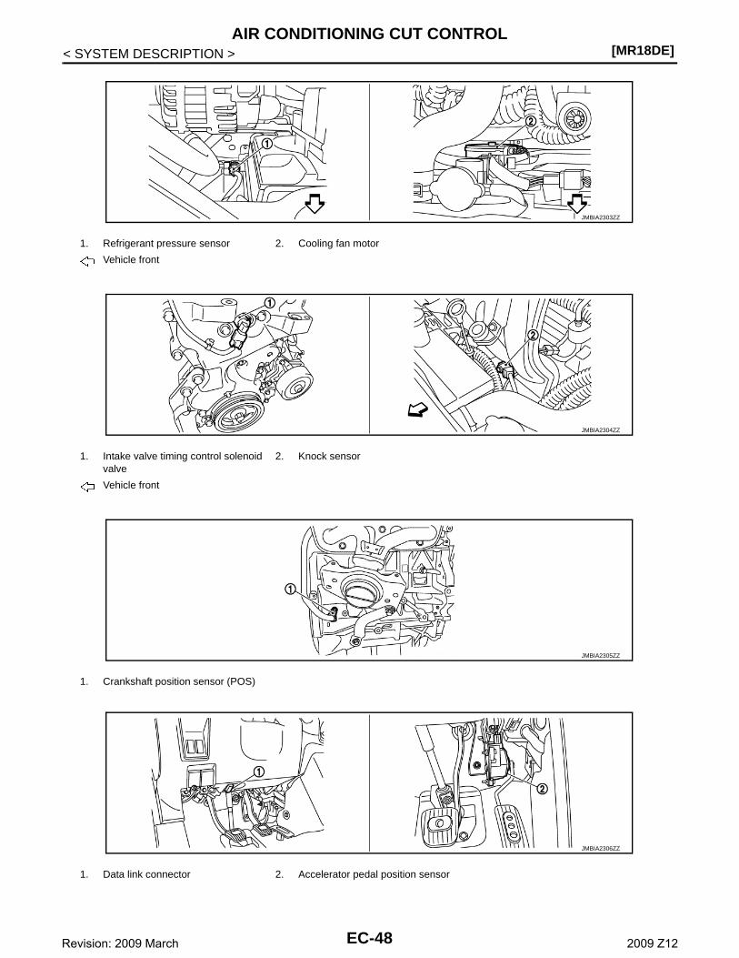
[MR18DE]AIR CONDITIONING CUT CONTROL
< SYSTEM DESCRIPTION >
1. Refrigerant pressure sensor 2. Cooling fan motor
Vehicle front
1. Intake valve timing control solenoid valve
2. Knock sensor
Vehicle front
1. Crankshaft position sensor (POS)
1. Data link connector 2. Accelerator pedal position sensor
JMBIA2303ZZ
JMBIA2304ZZ
JMBIA2305ZZ
JMBIA2306ZZ
EC-48Revision: 2009 March 2009 Z12
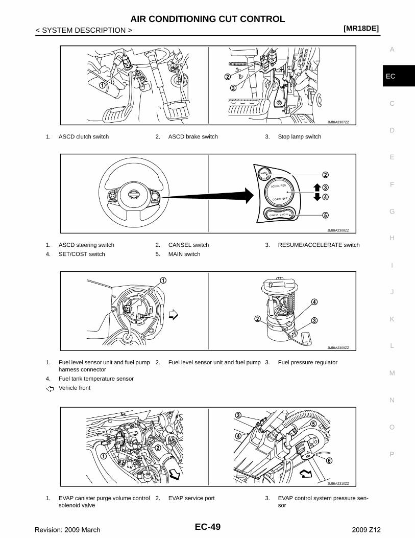
AIR CONDITIONING CUT CONTROL[MR18DE]
C
D
E
F
G
H
I
J
K
L
M
A
C
N
P
O
< SYSTEM DESCRIPTION >
E
1. ASCD clutch switch 2. ASCD brake switch 3. Stop lamp switch
1. ASCD steering switch 2. CANSEL switch 3. RESUME/ACCELERATE switch
4. SET/COST switch 5. MAIN switch
1. Fuel level sensor unit and fuel pump harness connector
2. Fuel level sensor unit and fuel pump 3. Fuel pressure regulator
4. Fuel tank temperature sensor
Vehicle front
1. EVAP canister purge volume control solenoid valve
2. EVAP service port 3. EVAP control system pressure sen-sor
JMBIA2307ZZ
JMBIA2308ZZ
JMBIA2309ZZ
JMBIA2310ZZ
EC-49Revision: 2009 March 2009 Z12
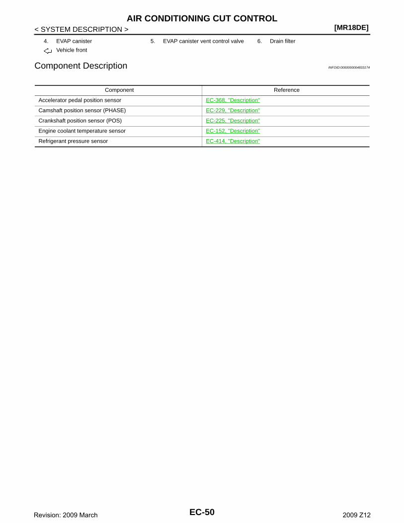
[MR18DE]AIR CONDITIONING CUT CONTROL
< SYSTEM DESCRIPTION >
Component Description INFOID:0000000004833174
4. EVAP canister 5. EVAP canister vent control valve 6. Drain filter
Vehicle front
Component Reference
Accelerator pedal position sensor EC-368, "Description"
Camshaft position sensor (PHASE) EC-229, "Description"
Crankshaft position sensor (POS) EC-225, "Description"
Engine coolant temperature sensor EC-152, "Description"
Refrigerant pressure sensor EC-414, "Description"
EC-50Revision: 2009 March 2009 Z12
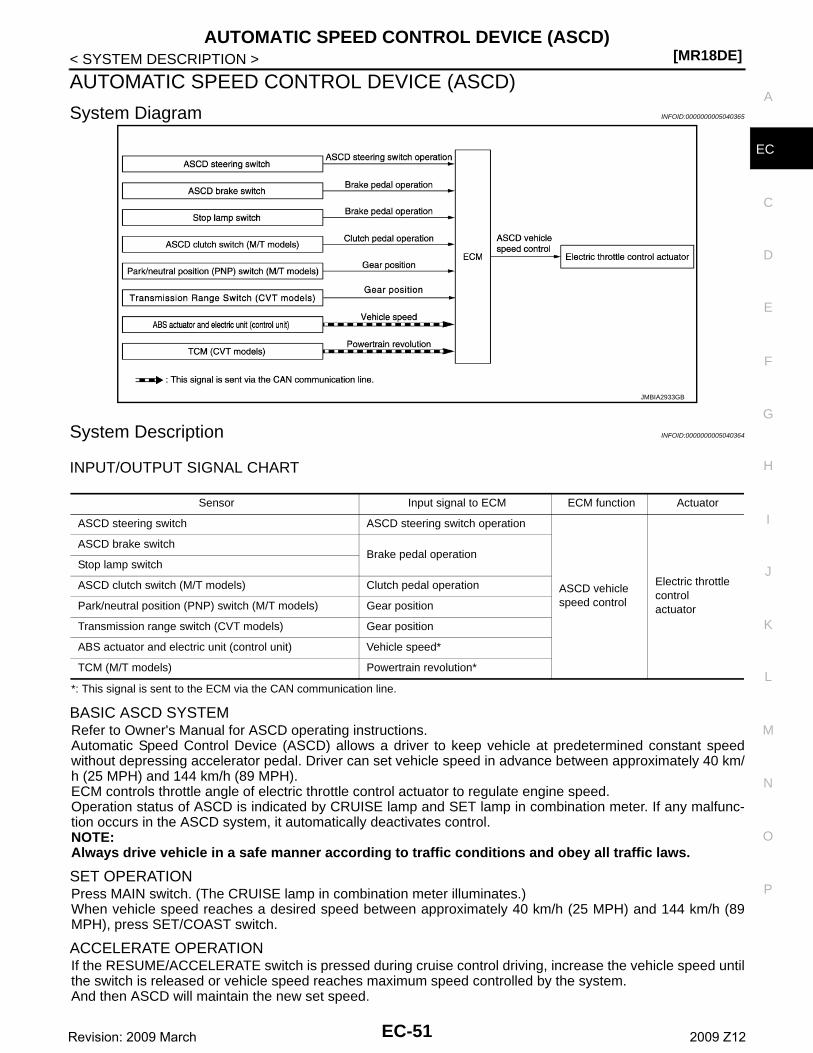
AUTOMATIC SPEED CONTROL DEVICE (ASCD)[MR18DE]
C
D
E
F
G
H
I
J
K
L
M
A
C
N
P
O
< SYSTEM DESCRIPTION >
E
AUTOMATIC SPEED CONTROL DEVICE (ASCD)
System Diagram INFOID:0000000005040365
System Description INFOID:0000000005040364
INPUT/OUTPUT SIGNAL CHART
*: This signal is sent to the ECM via the CAN communication line.
BASIC ASCD SYSTEMRefer to Owner's Manual for ASCD operating instructions.Automatic Speed Control Device (ASCD) allows a driver to keep vehicle at predetermined constant speedwithout depressing accelerator pedal. Driver can set vehicle speed in advance between approximately 40 km/h (25 MPH) and 144 km/h (89 MPH).ECM controls throttle angle of electric throttle control actuator to regulate engine speed.Operation status of ASCD is indicated by CRUISE lamp and SET lamp in combination meter. If any malfunc-tion occurs in the ASCD system, it automatically deactivates control.NOTE:Always drive vehicle in a safe manner according to traffic conditions and obey all traffic laws.
SET OPERATIONPress MAIN switch. (The CRUISE lamp in combination meter illuminates.)When vehicle speed reaches a desired speed between approximately 40 km/h (25 MPH) and 144 km/h (89MPH), press SET/COAST switch.
ACCELERATE OPERATIONIf the RESUME/ACCELERATE switch is pressed during cruise control driving, increase the vehicle speed untilthe switch is released or vehicle speed reaches maximum speed controlled by the system.And then ASCD will maintain the new set speed.
JMBIA2933GB
Sensor Input signal to ECM ECM function Actuator
ASCD steering switch ASCD steering switch operation
ASCD vehicle speed control
Electric throttle control actuator
ASCD brake switchBrake pedal operation
Stop lamp switch
ASCD clutch switch (M/T models) Clutch pedal operation
Park/neutral position (PNP) switch (M/T models) Gear position
Transmission range switch (CVT models) Gear position
ABS actuator and electric unit (control unit) Vehicle speed*
TCM (M/T models) Powertrain revolution*
EC-51Revision: 2009 March 2009 Z12
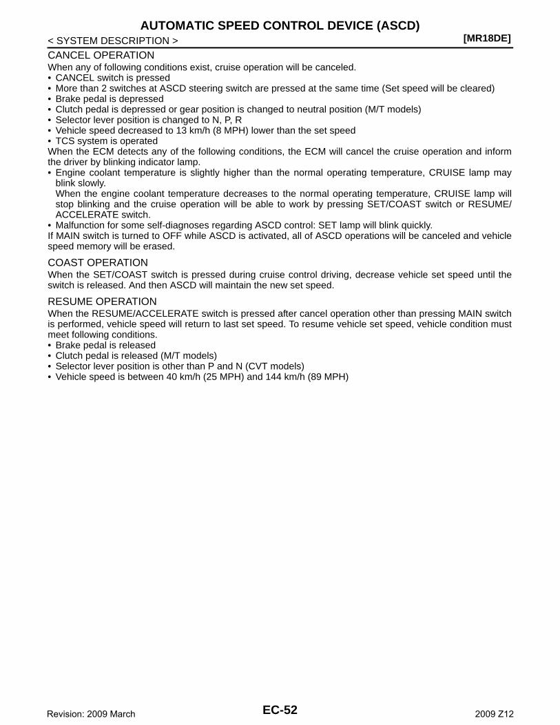
[MR18DE]AUTOMATIC SPEED CONTROL DEVICE (ASCD)
< SYSTEM DESCRIPTION >
CANCEL OPERATIONWhen any of following conditions exist, cruise operation will be canceled.• CANCEL switch is pressed• More than 2 switches at ASCD steering switch are pressed at the same time (Set speed will be cleared)• Brake pedal is depressed• Clutch pedal is depressed or gear position is changed to neutral position (M/T models)• Selector lever position is changed to N, P, R• Vehicle speed decreased to 13 km/h (8 MPH) lower than the set speed• TCS system is operatedWhen the ECM detects any of the following conditions, the ECM will cancel the cruise operation and informthe driver by blinking indicator lamp.• Engine coolant temperature is slightly higher than the normal operating temperature, CRUISE lamp may
blink slowly.When the engine coolant temperature decreases to the normal operating temperature, CRUISE lamp willstop blinking and the cruise operation will be able to work by pressing SET/COAST switch or RESUME/ACCELERATE switch.
• Malfunction for some self-diagnoses regarding ASCD control: SET lamp will blink quickly.If MAIN switch is turned to OFF while ASCD is activated, all of ASCD operations will be canceled and vehiclespeed memory will be erased.
COAST OPERATIONWhen the SET/COAST switch is pressed during cruise control driving, decrease vehicle set speed until theswitch is released. And then ASCD will maintain the new set speed.
RESUME OPERATIONWhen the RESUME/ACCELERATE switch is pressed after cancel operation other than pressing MAIN switchis performed, vehicle speed will return to last set speed. To resume vehicle set speed, vehicle condition mustmeet following conditions.• Brake pedal is released• Clutch pedal is released (M/T models)• Selector lever position is other than P and N (CVT models)• Vehicle speed is between 40 km/h (25 MPH) and 144 km/h (89 MPH)
EC-52Revision: 2009 March 2009 Z12
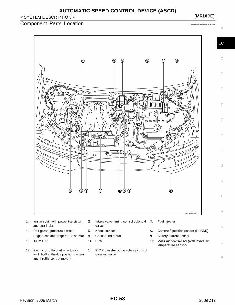
AUTOMATIC SPEED CONTROL DEVICE (ASCD)[MR18DE]
C
D
E
F
G
H
I
J
K
L
M
A
C
N
P
O
< SYSTEM DESCRIPTION >
E
Component Parts Location INFOID:0000000005039298
1. Ignition coil (with power transistor) and spark plug
2. Intake valve timing control solenoid valve
3. Fuel injector
4. Refrigerant pressure sensor 5. Knock sensor 6. Camshaft position sensor (PHASE)
7. Engine coolant temperature sensor 8. Cooling fan motor 9. Battery current sensor
10. IPDM E/R 11. ECM 12. Mass air flow sensor (with intake air temperature sensor)
13. Electric throttle control actuator(with built in throttle position sensor and throttle control motor)
14. EVAP canister purge volume control solenoid valve
JMBIA2296ZZ
EC-53Revision: 2009 March 2009 Z12
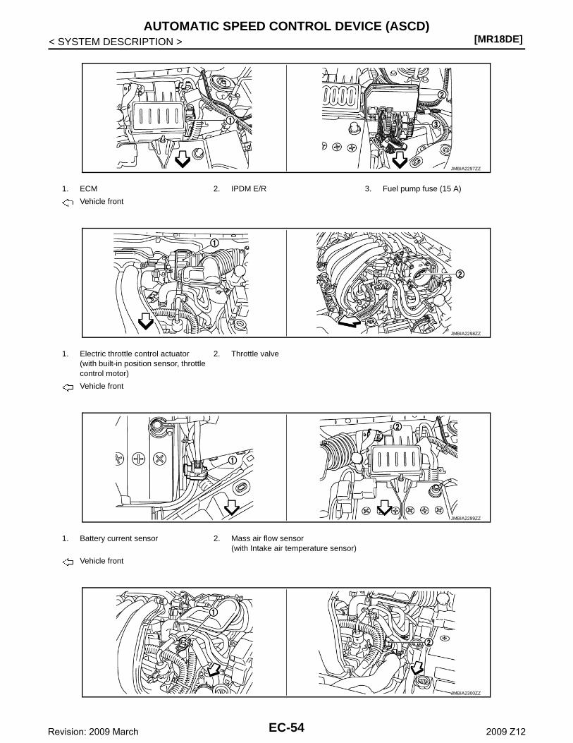
[MR18DE]AUTOMATIC SPEED CONTROL DEVICE (ASCD)
< SYSTEM DESCRIPTION >
1. ECM 2. IPDM E/R 3. Fuel pump fuse (15 A)
Vehicle front
1. Electric throttle control actuator(with built-in position sensor, throttle control motor)
2. Throttle valve
Vehicle front
1. Battery current sensor 2. Mass air flow sensor(with Intake air temperature sensor)
Vehicle front
JMBIA2297ZZ
JMBIA2298ZZ
JMBIA2299ZZ
JMBIA2300ZZ
EC-54Revision: 2009 March 2009 Z12

AUTOMATIC SPEED CONTROL DEVICE (ASCD)[MR18DE]
C
D
E
F
G
H
I
J
K
L
M
A
C
N
P
O
< SYSTEM DESCRIPTION >
E
1. Camshaft position sensor (PHASE) 2. Engine coolant temperature sensor
Vehicle front
1. Air fuel ratio (A/F) sensor 1 2. Three way catalyst (Manifold) 3. Heated oxygen sensor 2
4. Three way catalyst (under floor) 5. Muffler
Vehicle front
1. Air fuel ratio (A/F) sensor 1 harness connector
2. Air fuel ratio (A/F) sensor 1 3. Heated oxygen sensor 2
4. Heated oxygen sensor 2 harness connector
Vehicle front
1. PCV valve 2. Ignition coil (with power transistor) and spark plug
3. Fuel injector
Vehicle front
JMBIA2192ZZ
JMBIA2301ZZ
JMBIA2302ZZ
EC-55Revision: 2009 March 2009 Z12

[MR18DE]AUTOMATIC SPEED CONTROL DEVICE (ASCD)
< SYSTEM DESCRIPTION >
1. Refrigerant pressure sensor 2. Cooling fan motor
Vehicle front
1. Intake valve timing control solenoid valve
2. Knock sensor
Vehicle front
1. Crankshaft position sensor (POS)
1. Data link connector 2. Accelerator pedal position sensor
JMBIA2303ZZ
JMBIA2304ZZ
JMBIA2305ZZ
JMBIA2306ZZ
EC-56Revision: 2009 March 2009 Z12
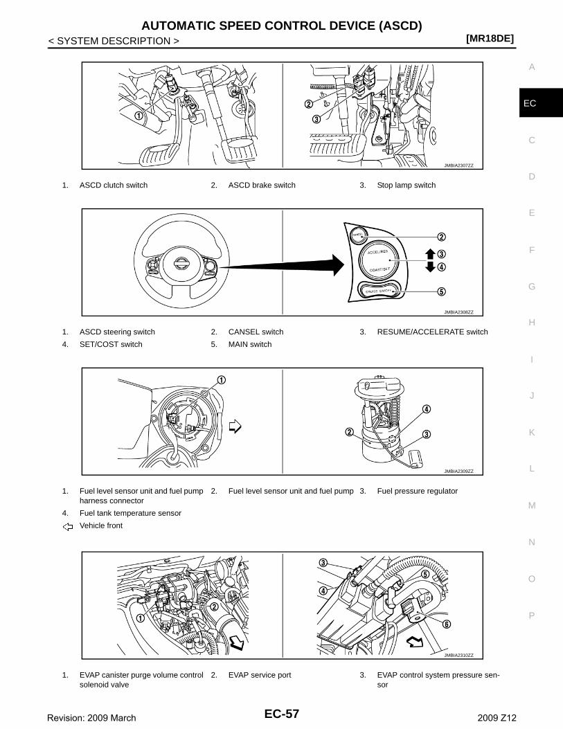
AUTOMATIC SPEED CONTROL DEVICE (ASCD)[MR18DE]
C
D
E
F
G
H
I
J
K
L
M
A
C
N
P
O
< SYSTEM DESCRIPTION >
E
1. ASCD clutch switch 2. ASCD brake switch 3. Stop lamp switch
1. ASCD steering switch 2. CANSEL switch 3. RESUME/ACCELERATE switch
4. SET/COST switch 5. MAIN switch
1. Fuel level sensor unit and fuel pump harness connector
2. Fuel level sensor unit and fuel pump 3. Fuel pressure regulator
4. Fuel tank temperature sensor
Vehicle front
1. EVAP canister purge volume control solenoid valve
2. EVAP service port 3. EVAP control system pressure sen-sor
JMBIA2307ZZ
JMBIA2308ZZ
JMBIA2309ZZ
JMBIA2310ZZ
EC-57Revision: 2009 March 2009 Z12
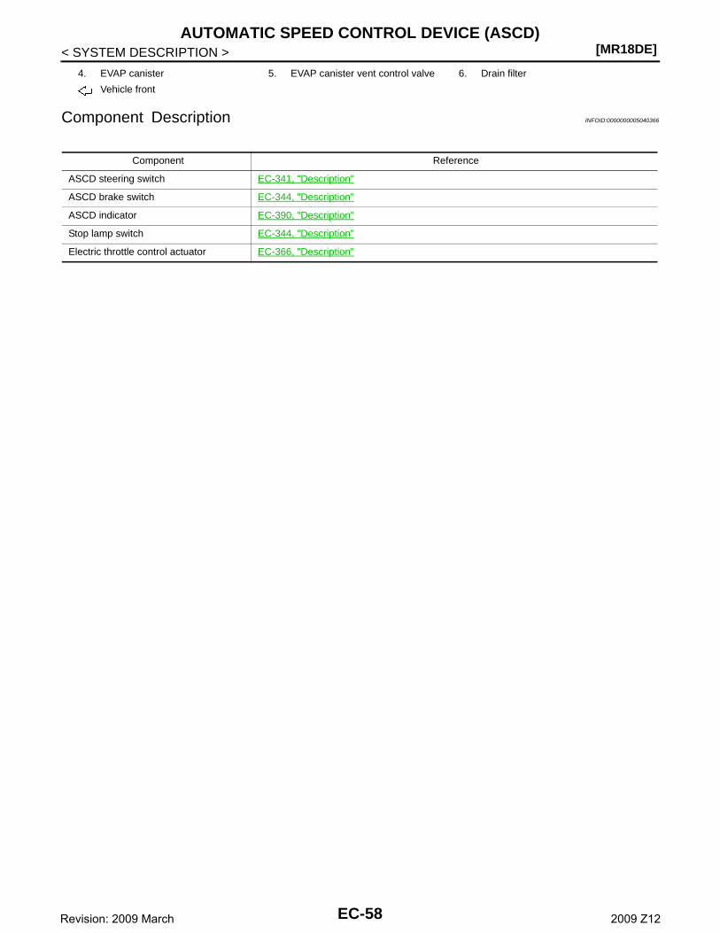
[MR18DE]AUTOMATIC SPEED CONTROL DEVICE (ASCD)
< SYSTEM DESCRIPTION >
Component Description INFOID:0000000005040366
4. EVAP canister 5. EVAP canister vent control valve 6. Drain filter
Vehicle front
Component Reference
ASCD steering switch EC-341, "Description"
ASCD brake switch EC-344, "Description"
ASCD indicator EC-390, "Description"
Stop lamp switch EC-344, "Description"
Electric throttle control actuator EC-366, "Description"
EC-58Revision: 2009 March 2009 Z12
CAN COMMUNICATION[MR18DE]
C
D
E
F
G
H
I
J
K
L
M
A
C
N
P
O
< SYSTEM DESCRIPTION >
E
CAN COMMUNICATION
System Description INFOID:0000000004833175
CAN (Controller Area Network) is a serial communication line for real time application. It is an on-vehicle mul-tiplex communication line with high data communication speed and excellent error detection ability. Many elec-tronic control units are equipped onto a vehicle, and each control unit shares information and links with othercontrol units during operation (not independent). In CAN communication, control units are connected with 2communication lines (CAN H line, CAN L line) allowing a high rate of information transmission with less wiring.Each control unit transmits/receives data but selectively reads required data only.Refer to LAN-23, "CAN Communication Signal Chart", about CAN communication for detail..
EC-59Revision: 2009 March 2009 Z12
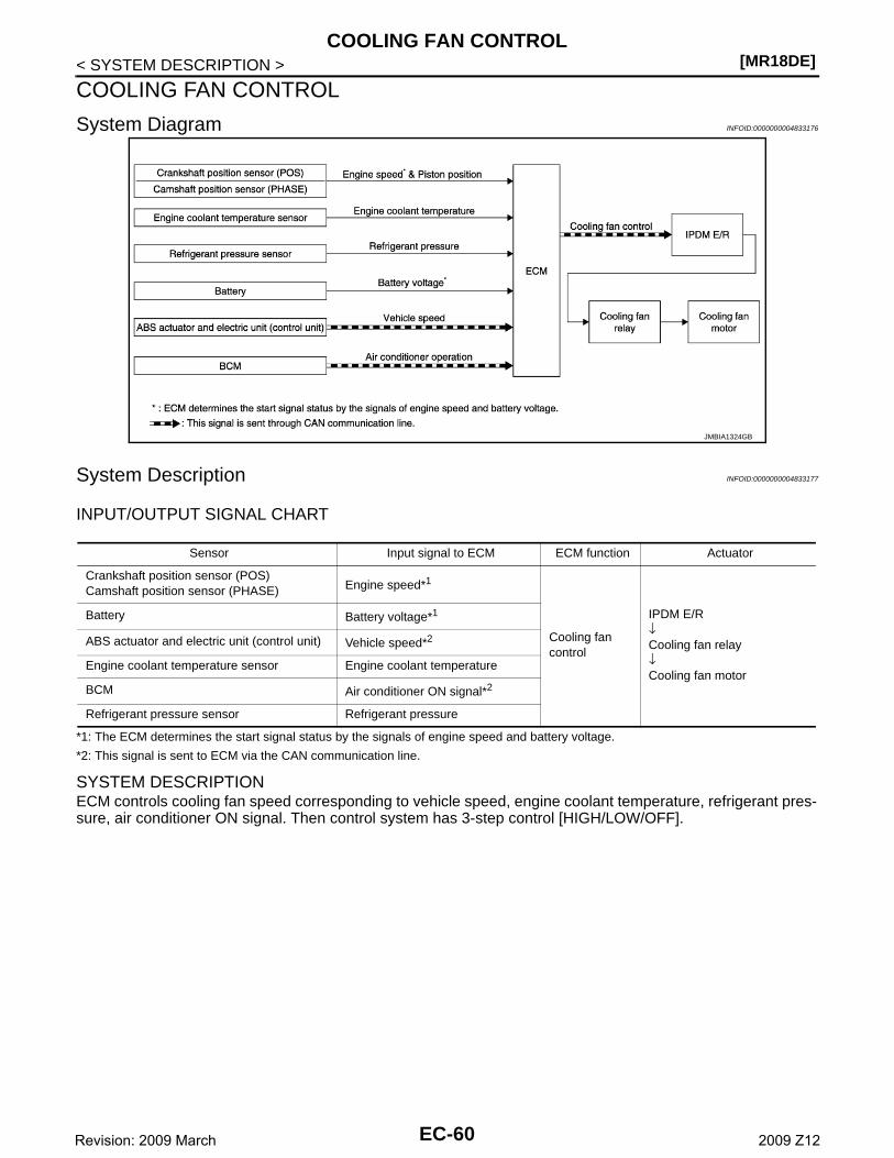
[MR18DE]COOLING FAN CONTROL
< SYSTEM DESCRIPTION >
COOLING FAN CONTROL
System Diagram INFOID:0000000004833176
System Description INFOID:0000000004833177
INPUT/OUTPUT SIGNAL CHART
*1: The ECM determines the start signal status by the signals of engine speed and battery voltage.
*2: This signal is sent to ECM via the CAN communication line.
SYSTEM DESCRIPTIONECM controls cooling fan speed corresponding to vehicle speed, engine coolant temperature, refrigerant pres-sure, air conditioner ON signal. Then control system has 3-step control [HIGH/LOW/OFF].
JMBIA1324GB
Sensor Input signal to ECM ECM function Actuator
Crankshaft position sensor (POS)Camshaft position sensor (PHASE) Engine speed*1
Cooling fan control
IPDM E/R↓Cooling fan relay↓Cooling fan motor
Battery Battery voltage*1
ABS actuator and electric unit (control unit) Vehicle speed*2
Engine coolant temperature sensor Engine coolant temperature
BCM Air conditioner ON signal*2
Refrigerant pressure sensor Refrigerant pressure
EC-60Revision: 2009 March 2009 Z12
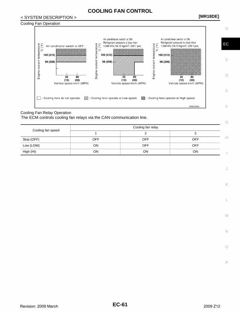
COOLING FAN CONTROL[MR18DE]
C
D
E
F
G
H
I
J
K
L
M
A
C
N
P
O
< SYSTEM DESCRIPTION >
E
Cooling Fan Operation
Cooling Fan Relay OperationThe ECM controls cooling fan relays via the CAN communication line.
PBIB2483E
Cooling fan speedCooling fan relay
1 2 3
Stop (OFF) OFF OFF OFF
Low (LOW) ON OFF OFF
High (HI) ON ON ON
EC-61Revision: 2009 March 2009 Z12
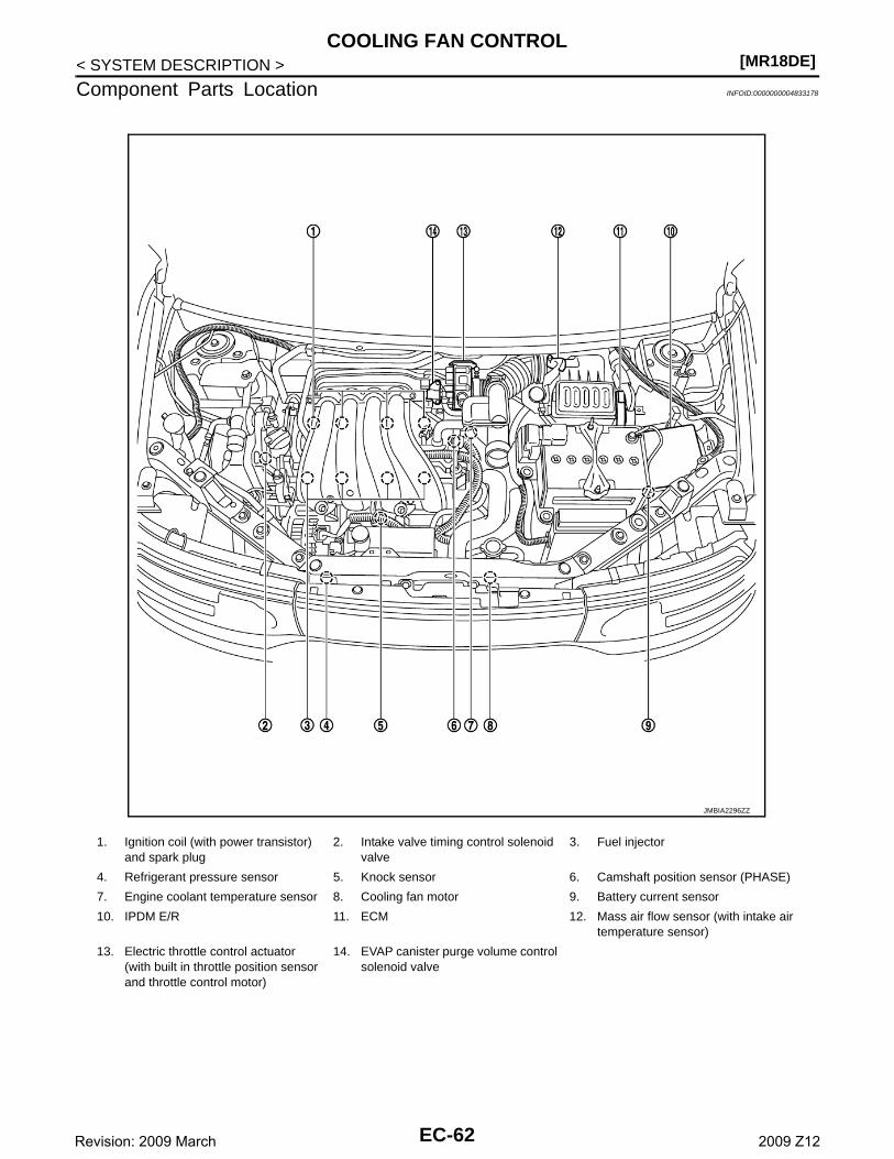
[MR18DE]COOLING FAN CONTROL
< SYSTEM DESCRIPTION >
Component Parts Location INFOID:0000000004833178
1. Ignition coil (with power transistor) and spark plug
2. Intake valve timing control solenoid valve
3. Fuel injector
4. Refrigerant pressure sensor 5. Knock sensor 6. Camshaft position sensor (PHASE)
7. Engine coolant temperature sensor 8. Cooling fan motor 9. Battery current sensor
10. IPDM E/R 11. ECM 12. Mass air flow sensor (with intake air temperature sensor)
13. Electric throttle control actuator(with built in throttle position sensor and throttle control motor)
14. EVAP canister purge volume control solenoid valve
JMBIA2296ZZ
EC-62Revision: 2009 March 2009 Z12

COOLING FAN CONTROL[MR18DE]
C
D
E
F
G
H
I
J
K
L
M
A
C
N
P
O
< SYSTEM DESCRIPTION >
E
1. ECM 2. IPDM E/R 3. Fuel pump fuse (15 A)
Vehicle front
1. Electric throttle control actuator(with built-in position sensor, throttle control motor)
2. Throttle valve
Vehicle front
1. Battery current sensor 2. Mass air flow sensor(with Intake air temperature sensor)
Vehicle front
JMBIA2297ZZ
JMBIA2298ZZ
JMBIA2299ZZ
JMBIA2300ZZ
EC-63Revision: 2009 March 2009 Z12
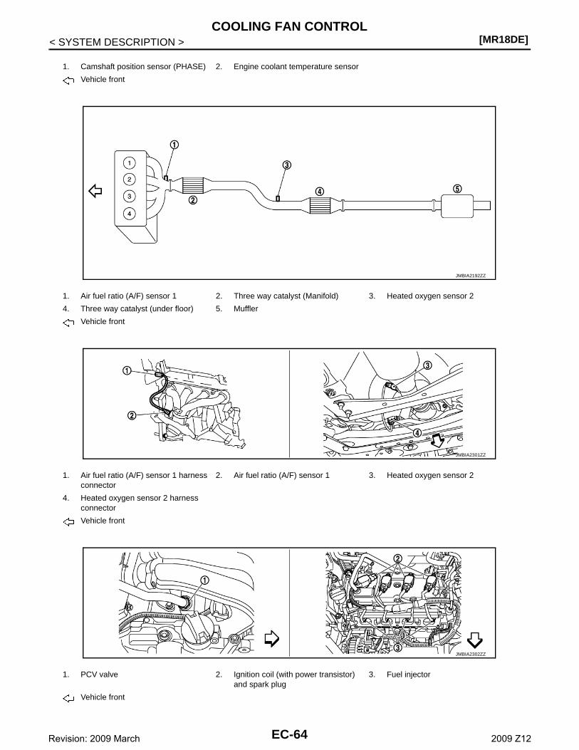
[MR18DE]COOLING FAN CONTROL
< SYSTEM DESCRIPTION >
1. Camshaft position sensor (PHASE) 2. Engine coolant temperature sensor
Vehicle front
1. Air fuel ratio (A/F) sensor 1 2. Three way catalyst (Manifold) 3. Heated oxygen sensor 2
4. Three way catalyst (under floor) 5. Muffler
Vehicle front
1. Air fuel ratio (A/F) sensor 1 harness connector
2. Air fuel ratio (A/F) sensor 1 3. Heated oxygen sensor 2
4. Heated oxygen sensor 2 harness connector
Vehicle front
1. PCV valve 2. Ignition coil (with power transistor) and spark plug
3. Fuel injector
Vehicle front
JMBIA2192ZZ
JMBIA2301ZZ
JMBIA2302ZZ
EC-64Revision: 2009 March 2009 Z12
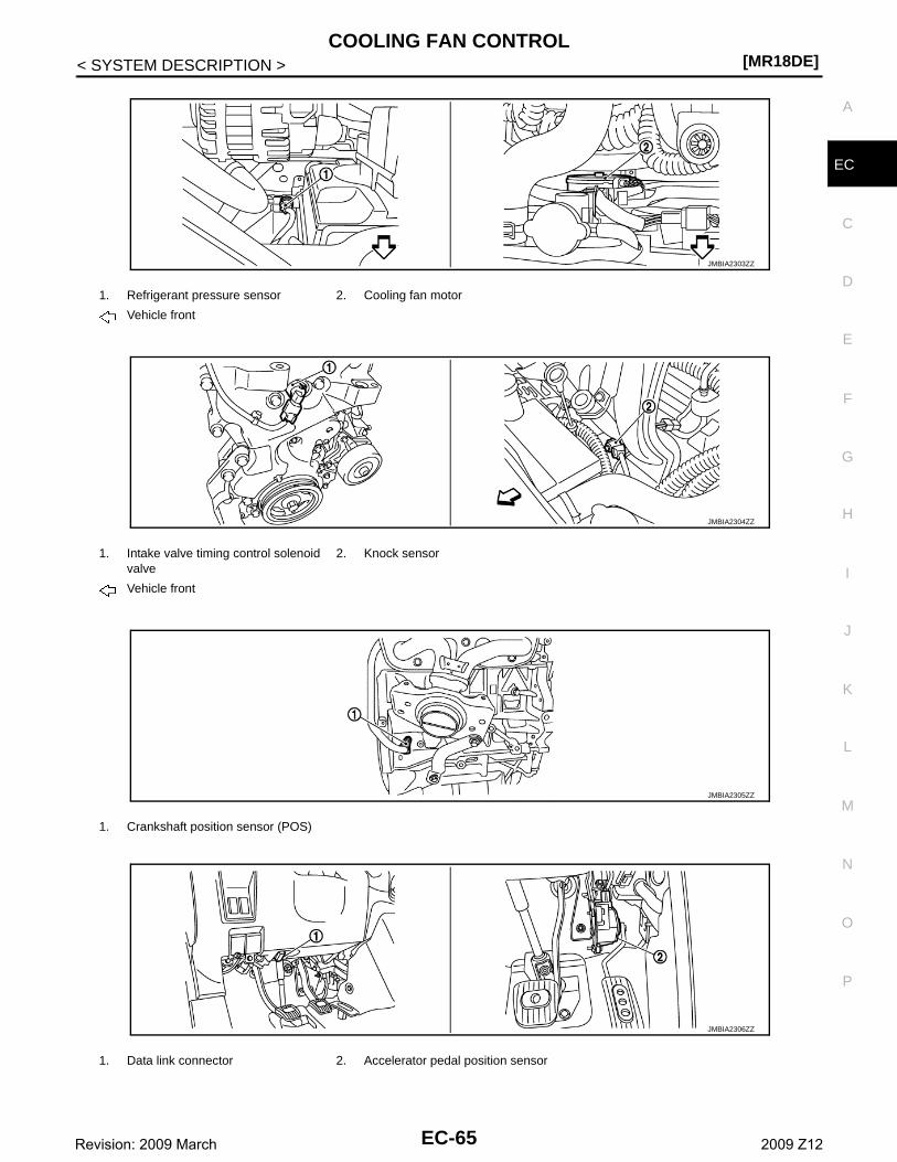
COOLING FAN CONTROL[MR18DE]
C
D
E
F
G
H
I
J
K
L
M
A
C
N
P
O
< SYSTEM DESCRIPTION >
E
1. Refrigerant pressure sensor 2. Cooling fan motor
Vehicle front
1. Intake valve timing control solenoid valve
2. Knock sensor
Vehicle front
1. Crankshaft position sensor (POS)
1. Data link connector 2. Accelerator pedal position sensor
JMBIA2303ZZ
JMBIA2304ZZ
JMBIA2305ZZ
JMBIA2306ZZ
EC-65Revision: 2009 March 2009 Z12
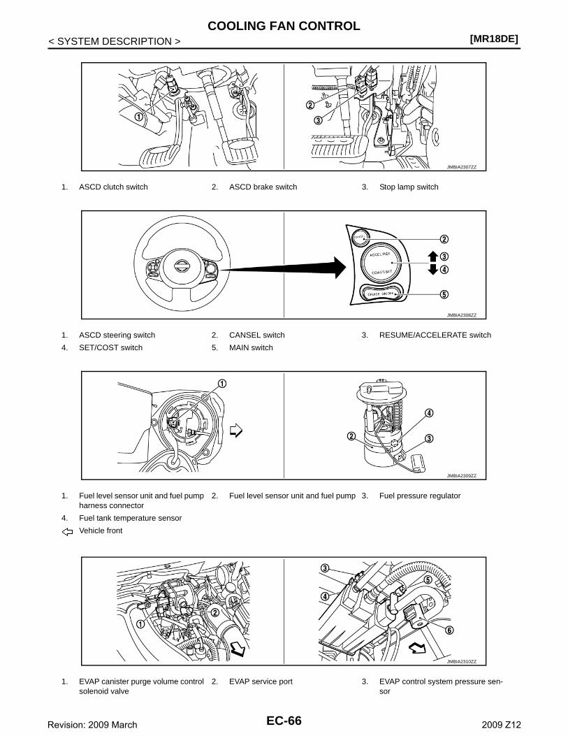
[MR18DE]COOLING FAN CONTROL
< SYSTEM DESCRIPTION >
1. ASCD clutch switch 2. ASCD brake switch 3. Stop lamp switch
1. ASCD steering switch 2. CANSEL switch 3. RESUME/ACCELERATE switch
4. SET/COST switch 5. MAIN switch
1. Fuel level sensor unit and fuel pump harness connector
2. Fuel level sensor unit and fuel pump 3. Fuel pressure regulator
4. Fuel tank temperature sensor
Vehicle front
1. EVAP canister purge volume control solenoid valve
2. EVAP service port 3. EVAP control system pressure sen-sor
JMBIA2307ZZ
JMBIA2308ZZ
JMBIA2309ZZ
JMBIA2310ZZ
EC-66Revision: 2009 March 2009 Z12
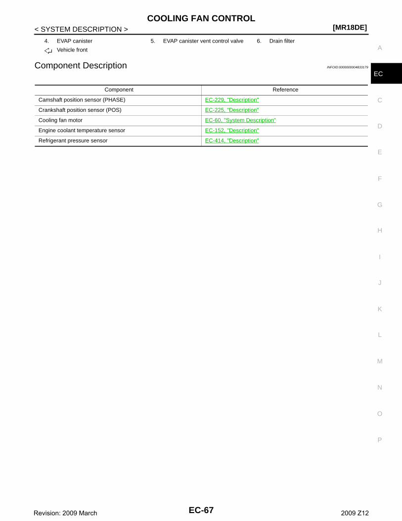
COOLING FAN CONTROL[MR18DE]
C
D
E
F
G
H
I
J
K
L
M
A
C
N
P
O
< SYSTEM DESCRIPTION >
EComponent Description INFOID:0000000004833179
4. EVAP canister 5. EVAP canister vent control valve 6. Drain filter
Vehicle front
Component Reference
Camshaft position sensor (PHASE) EC-229, "Description"
Crankshaft position sensor (POS) EC-225, "Description"
Cooling fan motor EC-60, "System Description"
Engine coolant temperature sensor EC-152, "Description"
Refrigerant pressure sensor EC-414, "Description"
EC-67Revision: 2009 March 2009 Z12
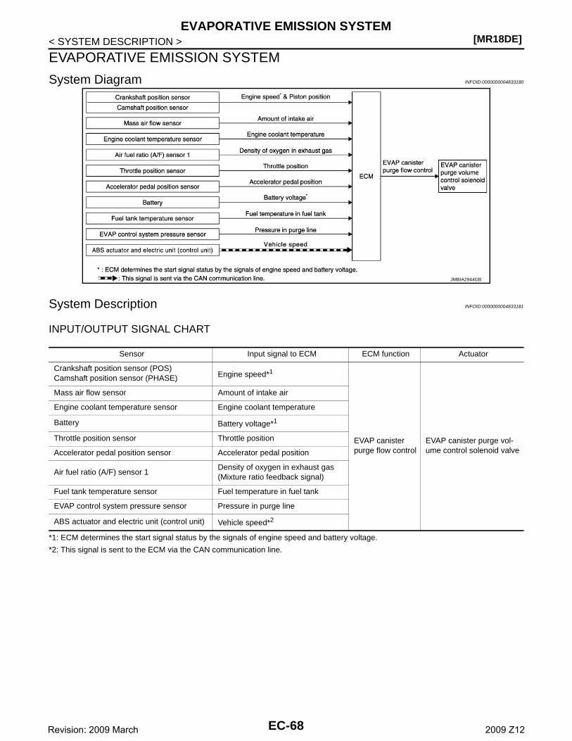
[MR18DE]EVAPORATIVE EMISSION SYSTEM
< SYSTEM DESCRIPTION >
EVAPORATIVE EMISSION SYSTEM
System Diagram INFOID:0000000004833180
System Description INFOID:0000000004833181
INPUT/OUTPUT SIGNAL CHART
*1: ECM determines the start signal status by the signals of engine speed and battery voltage.
*2: This signal is sent to the ECM via the CAN communication line.
JMBIA2944GB
Sensor Input signal to ECM ECM function Actuator
Crankshaft position sensor (POS)Camshaft position sensor (PHASE) Engine speed*1
EVAP canister purge flow control
EVAP canister purge vol-ume control solenoid valve
Mass air flow sensor Amount of intake air
Engine coolant temperature sensor Engine coolant temperature
Battery Battery voltage*1
Throttle position sensor Throttle position
Accelerator pedal position sensor Accelerator pedal position
Air fuel ratio (A/F) sensor 1Density of oxygen in exhaust gas(Mixture ratio feedback signal)
Fuel tank temperature sensor Fuel temperature in fuel tank
EVAP control system pressure sensor Pressure in purge line
ABS actuator and electric unit (control unit) Vehicle speed*2
EC-68Revision: 2009 March 2009 Z12
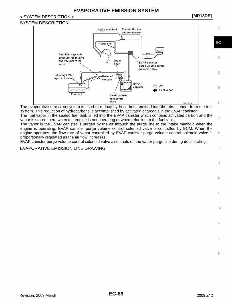
EVAPORATIVE EMISSION SYSTEM[MR18DE]
C
D
E
F
G
H
I
J
K
L
M
A
C
N
P
O
< SYSTEM DESCRIPTION >
E
SYSTEM DESCRIPTION
The evaporative emission system is used to reduce hydrocarbons emitted into the atmosphere from the fuelsystem. This reduction of hydrocarbons is accomplished by activated charcoals in the EVAP canister.The fuel vapor in the sealed fuel tank is led into the EVAP canister which contains activated carbon and thevapor is stored there when the engine is not operating or when refueling to the fuel tank.The vapor in the EVAP canister is purged by the air through the purge line to the intake manifold when theengine is operating. EVAP canister purge volume control solenoid valve is controlled by ECM. When theengine operates, the flow rate of vapor controlled by EVAP canister purge volume control solenoid valve isproportionally regulated as the air flow increases.EVAP canister purge volume control solenoid valve also shuts off the vapor purge line during decelerating.
EVAPORATIVE EMISSION LINE DRAWING
PBIB3639E
EC-69Revision: 2009 March 2009 Z12
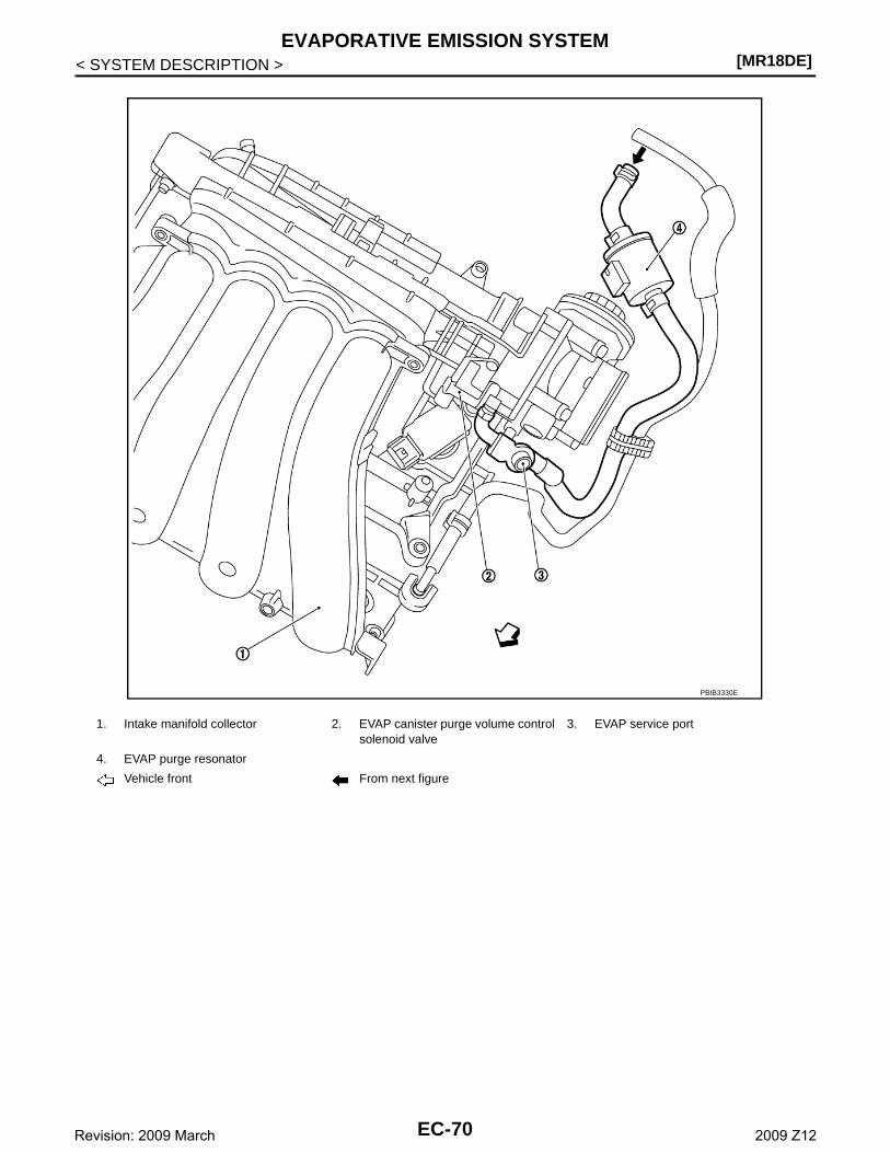
[MR18DE]EVAPORATIVE EMISSION SYSTEM
< SYSTEM DESCRIPTION >
1. Intake manifold collector 2. EVAP canister purge volume control solenoid valve
3. EVAP service port
4. EVAP purge resonator
Vehicle front From next figure
PBIB3330E
EC-70Revision: 2009 March 2009 Z12
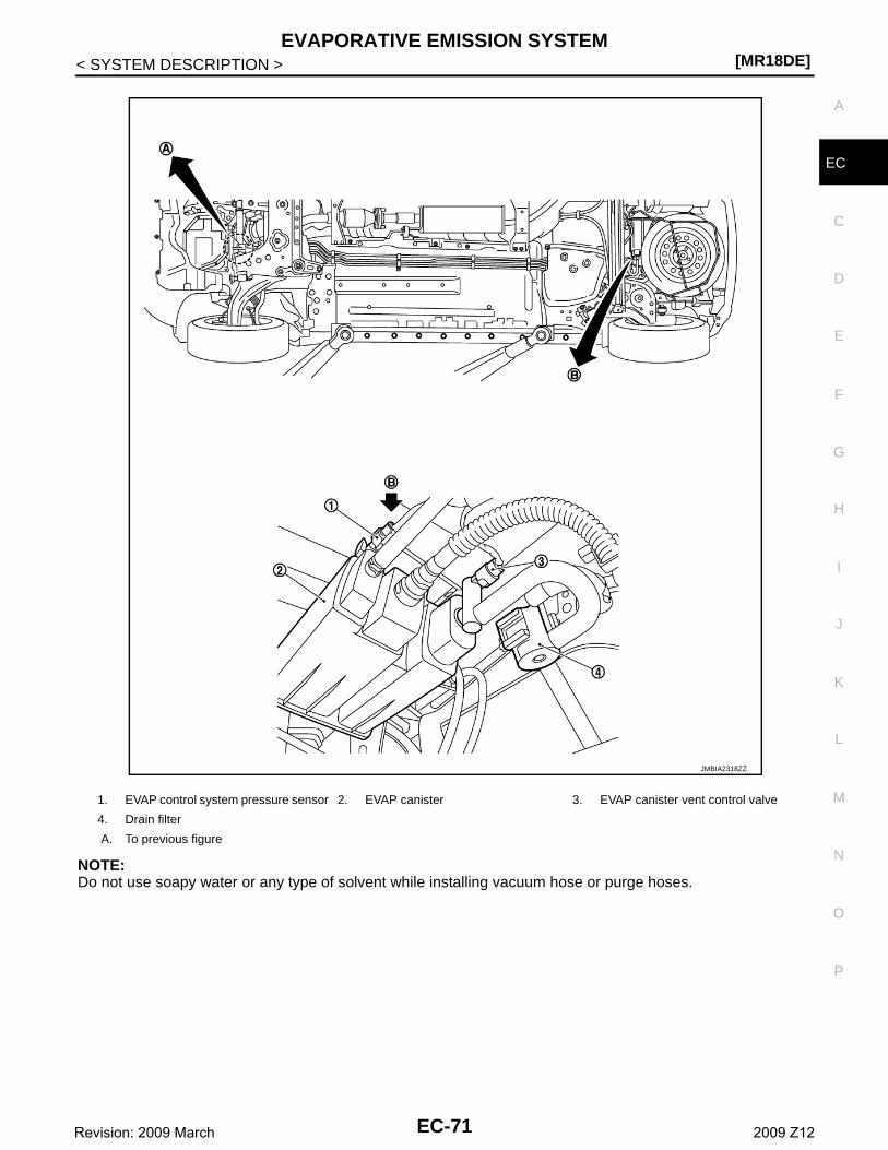
EVAPORATIVE EMISSION SYSTEM[MR18DE]
C
D
E
F
G
H
I
J
K
L
M
A
C
N
P
O
< SYSTEM DESCRIPTION >
E
NOTE:Do not use soapy water or any type of solvent while installing vacuum hose or purge hoses.
1. EVAP control system pressure sensor 2. EVAP canister 3. EVAP canister vent control valve
4. Drain filter
A. To previous figure
JMBIA2318ZZ
EC-71Revision: 2009 March 2009 Z12
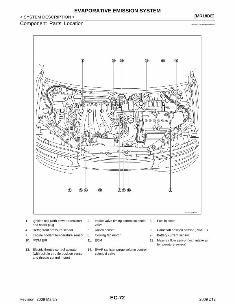
[MR18DE]EVAPORATIVE EMISSION SYSTEM
< SYSTEM DESCRIPTION >
Component Parts Location INFOID:0000000004833182
1. Ignition coil (with power transistor) and spark plug
2. Intake valve timing control solenoid valve
3. Fuel injector
4. Refrigerant pressure sensor 5. Knock sensor 6. Camshaft position sensor (PHASE)
7. Engine coolant temperature sensor 8. Cooling fan motor 9. Battery current sensor
10. IPDM E/R 11. ECM 12. Mass air flow sensor (with intake air temperature sensor)
13. Electric throttle control actuator(with built in throttle position sensor and throttle control motor)
14. EVAP canister purge volume control solenoid valve
JMBIA2296ZZ
EC-72Revision: 2009 March 2009 Z12
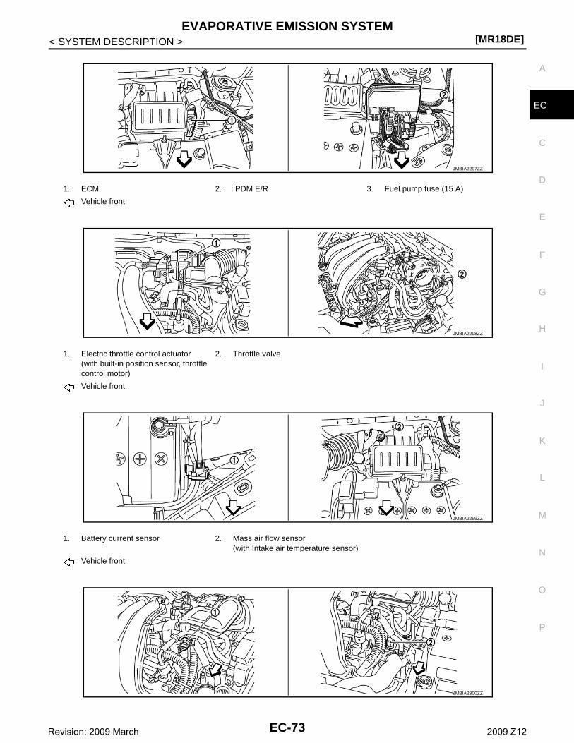
EVAPORATIVE EMISSION SYSTEM[MR18DE]
C
D
E
F
G
H
I
J
K
L
M
A
C
N
P
O
< SYSTEM DESCRIPTION >
E
1. ECM 2. IPDM E/R 3. Fuel pump fuse (15 A)
Vehicle front
1. Electric throttle control actuator(with built-in position sensor, throttle control motor)
2. Throttle valve
Vehicle front
1. Battery current sensor 2. Mass air flow sensor(with Intake air temperature sensor)
Vehicle front
JMBIA2297ZZ
JMBIA2298ZZ
JMBIA2299ZZ
JMBIA2300ZZ
EC-73Revision: 2009 March 2009 Z12

[MR18DE]EVAPORATIVE EMISSION SYSTEM
< SYSTEM DESCRIPTION >
1. Camshaft position sensor (PHASE) 2. Engine coolant temperature sensor
Vehicle front
1. Air fuel ratio (A/F) sensor 1 2. Three way catalyst (Manifold) 3. Heated oxygen sensor 2
4. Three way catalyst (under floor) 5. Muffler
Vehicle front
1. Air fuel ratio (A/F) sensor 1 harness connector
2. Air fuel ratio (A/F) sensor 1 3. Heated oxygen sensor 2
4. Heated oxygen sensor 2 harness connector
Vehicle front
1. PCV valve 2. Ignition coil (with power transistor) and spark plug
3. Fuel injector
Vehicle front
JMBIA2192ZZ
JMBIA2301ZZ
JMBIA2302ZZ
EC-74Revision: 2009 March 2009 Z12

EVAPORATIVE EMISSION SYSTEM[MR18DE]
C
D
E
F
G
H
I
J
K
L
M
A
C
N
P
O
< SYSTEM DESCRIPTION >
E
1. Refrigerant pressure sensor 2. Cooling fan motor
Vehicle front
1. Intake valve timing control solenoid valve
2. Knock sensor
Vehicle front
1. Crankshaft position sensor (POS)
1. Data link connector 2. Accelerator pedal position sensor
JMBIA2303ZZ
JMBIA2304ZZ
JMBIA2305ZZ
JMBIA2306ZZ
EC-75Revision: 2009 March 2009 Z12

[MR18DE]EVAPORATIVE EMISSION SYSTEM
< SYSTEM DESCRIPTION >
1. ASCD clutch switch 2. ASCD brake switch 3. Stop lamp switch
1. ASCD steering switch 2. CANSEL switch 3. RESUME/ACCELERATE switch
4. SET/COST switch 5. MAIN switch
1. Fuel level sensor unit and fuel pump harness connector
2. Fuel level sensor unit and fuel pump 3. Fuel pressure regulator
4. Fuel tank temperature sensor
Vehicle front
1. EVAP canister purge volume control solenoid valve
2. EVAP service port 3. EVAP control system pressure sen-sor
JMBIA2307ZZ
JMBIA2308ZZ
JMBIA2309ZZ
JMBIA2310ZZ
EC-76Revision: 2009 March 2009 Z12
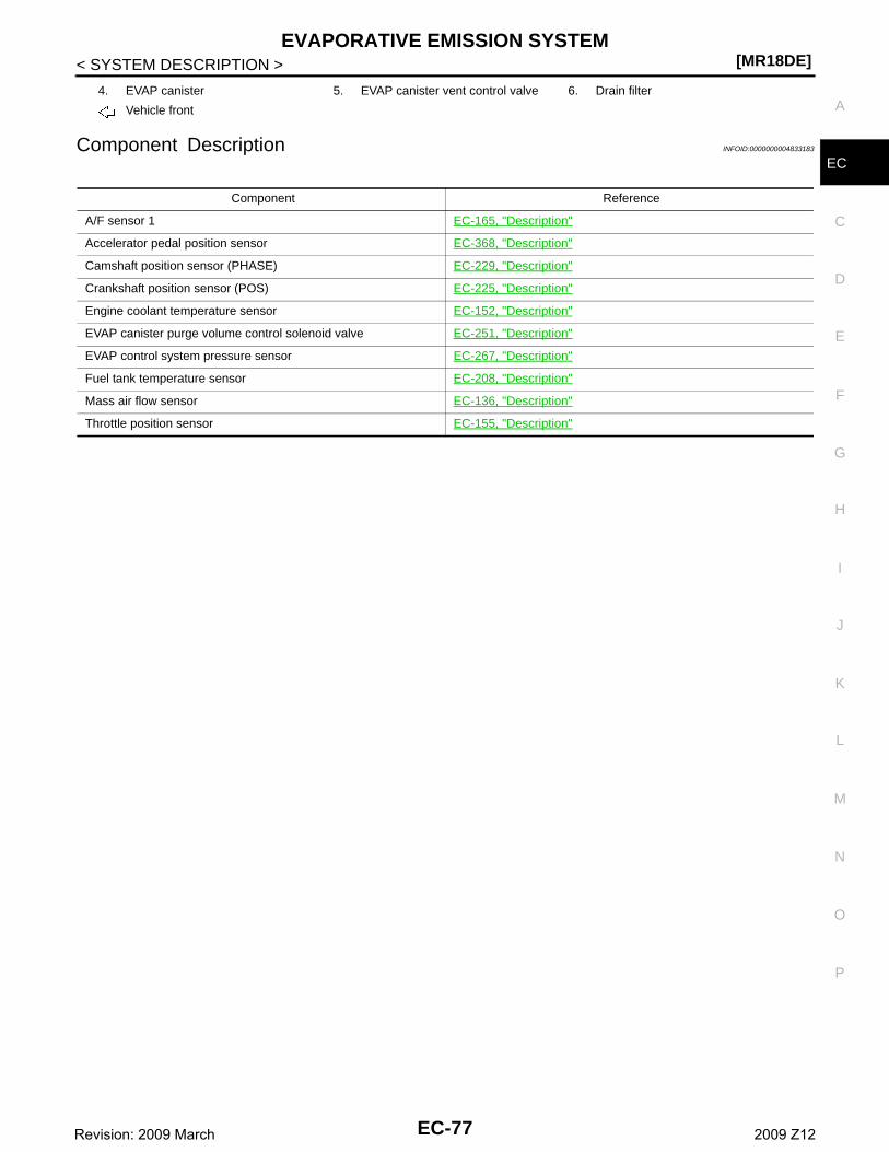
EVAPORATIVE EMISSION SYSTEM[MR18DE]
C
D
E
F
G
H
I
J
K
L
M
A
C
N
P
O
< SYSTEM DESCRIPTION >
EComponent Description INFOID:0000000004833183
4. EVAP canister 5. EVAP canister vent control valve 6. Drain filter
Vehicle front
Component Reference
A/F sensor 1 EC-165, "Description"
Accelerator pedal position sensor EC-368, "Description"
Camshaft position sensor (PHASE) EC-229, "Description"
Crankshaft position sensor (POS) EC-225, "Description"
Engine coolant temperature sensor EC-152, "Description"
EVAP canister purge volume control solenoid valve EC-251, "Description"
EVAP control system pressure sensor EC-267, "Description"
Fuel tank temperature sensor EC-208, "Description"
Mass air flow sensor EC-136, "Description"
Throttle position sensor EC-155, "Description"
EC-77Revision: 2009 March 2009 Z12
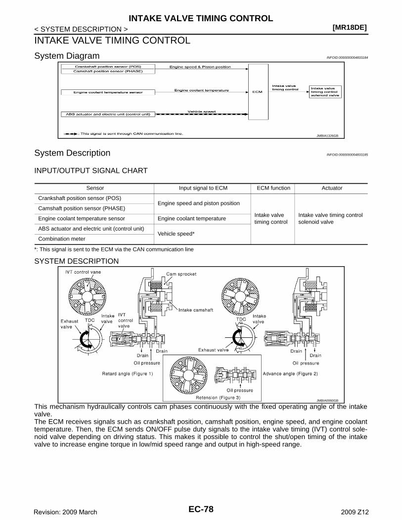
[MR18DE]INTAKE VALVE TIMING CONTROL
< SYSTEM DESCRIPTION >
INTAKE VALVE TIMING CONTROL
System Diagram INFOID:0000000004833184
System Description INFOID:0000000004833185
INPUT/OUTPUT SIGNAL CHART
*: This signal is sent to the ECM via the CAN communication line
SYSTEM DESCRIPTION
This mechanism hydraulically controls cam phases continuously with the fixed operating angle of the intakevalve.The ECM receives signals such as crankshaft position, camshaft position, engine speed, and engine coolanttemperature. Then, the ECM sends ON/OFF pulse duty signals to the intake valve timing (IVT) control sole-noid valve depending on driving status. This makes it possible to control the shut/open timing of the intakevalve to increase engine torque in low/mid speed range and output in high-speed range.
JMBIA1326GB
Sensor Input signal to ECM ECM function Actuator
Crankshaft position sensor (POS)Engine speed and piston position
Intake valve timing control
Intake valve timing control solenoid valve
Camshaft position sensor (PHASE)
Engine coolant temperature sensor Engine coolant temperature
ABS actuator and electric unit (control unit)Vehicle speed*
Combination meter
JMBIA0060GB
EC-78Revision: 2009 March 2009 Z12

INTAKE VALVE TIMING CONTROL[MR18DE]
C
D
E
F
G
H
I
J
K
L
M
A
C
N
P
O
< SYSTEM DESCRIPTION >
E
Component Parts Location INFOID:0000000004833186
1. Ignition coil (with power transistor) and spark plug
2. Intake valve timing control solenoid valve
3. Fuel injector
4. Refrigerant pressure sensor 5. Knock sensor 6. Camshaft position sensor (PHASE)
7. Engine coolant temperature sensor 8. Cooling fan motor 9. Battery current sensor
10. IPDM E/R 11. ECM 12. Mass air flow sensor (with intake air temperature sensor)
13. Electric throttle control actuator(with built in throttle position sensor and throttle control motor)
14. EVAP canister purge volume control solenoid valve
JMBIA2296ZZ
EC-79Revision: 2009 March 2009 Z12
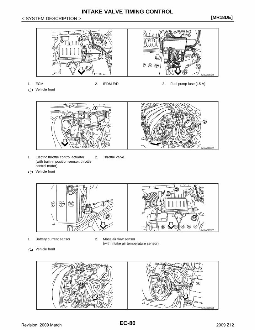
[MR18DE]INTAKE VALVE TIMING CONTROL
< SYSTEM DESCRIPTION >
1. ECM 2. IPDM E/R 3. Fuel pump fuse (15 A)
Vehicle front
1. Electric throttle control actuator(with built-in position sensor, throttle control motor)
2. Throttle valve
Vehicle front
1. Battery current sensor 2. Mass air flow sensor(with Intake air temperature sensor)
Vehicle front
JMBIA2297ZZ
JMBIA2298ZZ
JMBIA2299ZZ
JMBIA2300ZZ
EC-80Revision: 2009 March 2009 Z12

INTAKE VALVE TIMING CONTROL[MR18DE]
C
D
E
F
G
H
I
J
K
L
M
A
C
N
P
O
< SYSTEM DESCRIPTION >
E
1. Camshaft position sensor (PHASE) 2. Engine coolant temperature sensor
Vehicle front
1. Air fuel ratio (A/F) sensor 1 2. Three way catalyst (Manifold) 3. Heated oxygen sensor 2
4. Three way catalyst (under floor) 5. Muffler
Vehicle front
1. Air fuel ratio (A/F) sensor 1 harness connector
2. Air fuel ratio (A/F) sensor 1 3. Heated oxygen sensor 2
4. Heated oxygen sensor 2 harness connector
Vehicle front
1. PCV valve 2. Ignition coil (with power transistor) and spark plug
3. Fuel injector
Vehicle front
JMBIA2192ZZ
JMBIA2301ZZ
JMBIA2302ZZ
EC-81Revision: 2009 March 2009 Z12
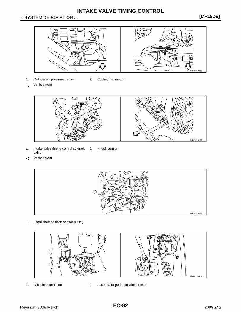
[MR18DE]INTAKE VALVE TIMING CONTROL
< SYSTEM DESCRIPTION >
1. Refrigerant pressure sensor 2. Cooling fan motor
Vehicle front
1. Intake valve timing control solenoid valve
2. Knock sensor
Vehicle front
1. Crankshaft position sensor (POS)
1. Data link connector 2. Accelerator pedal position sensor
JMBIA2303ZZ
JMBIA2304ZZ
JMBIA2305ZZ
JMBIA2306ZZ
EC-82Revision: 2009 March 2009 Z12
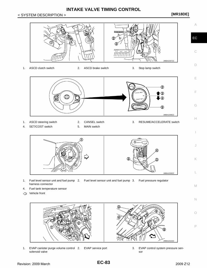
INTAKE VALVE TIMING CONTROL[MR18DE]
C
D
E
F
G
H
I
J
K
L
M
A
C
N
P
O
< SYSTEM DESCRIPTION >
E
1. ASCD clutch switch 2. ASCD brake switch 3. Stop lamp switch
1. ASCD steering switch 2. CANSEL switch 3. RESUME/ACCELERATE switch
4. SET/COST switch 5. MAIN switch
1. Fuel level sensor unit and fuel pump harness connector
2. Fuel level sensor unit and fuel pump 3. Fuel pressure regulator
4. Fuel tank temperature sensor
Vehicle front
1. EVAP canister purge volume control solenoid valve
2. EVAP service port 3. EVAP control system pressure sen-sor
JMBIA2307ZZ
JMBIA2308ZZ
JMBIA2309ZZ
JMBIA2310ZZ
EC-83Revision: 2009 March 2009 Z12
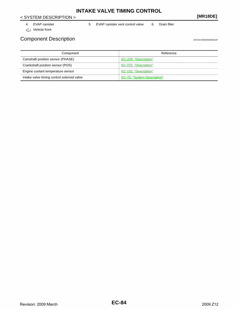
[MR18DE]INTAKE VALVE TIMING CONTROL
< SYSTEM DESCRIPTION >
Component Description INFOID:0000000004833187
4. EVAP canister 5. EVAP canister vent control valve 6. Drain filter
Vehicle front
Component Reference
Camshaft position sensor (PHASE) EC-229, "Description"
Crankshaft position sensor (POS) EC-225, "Description"
Engine coolant temperature sensor EC-152, "Description"
Intake valve timing control solenoid valve EC-78, "System Description"
EC-84Revision: 2009 March 2009 Z12
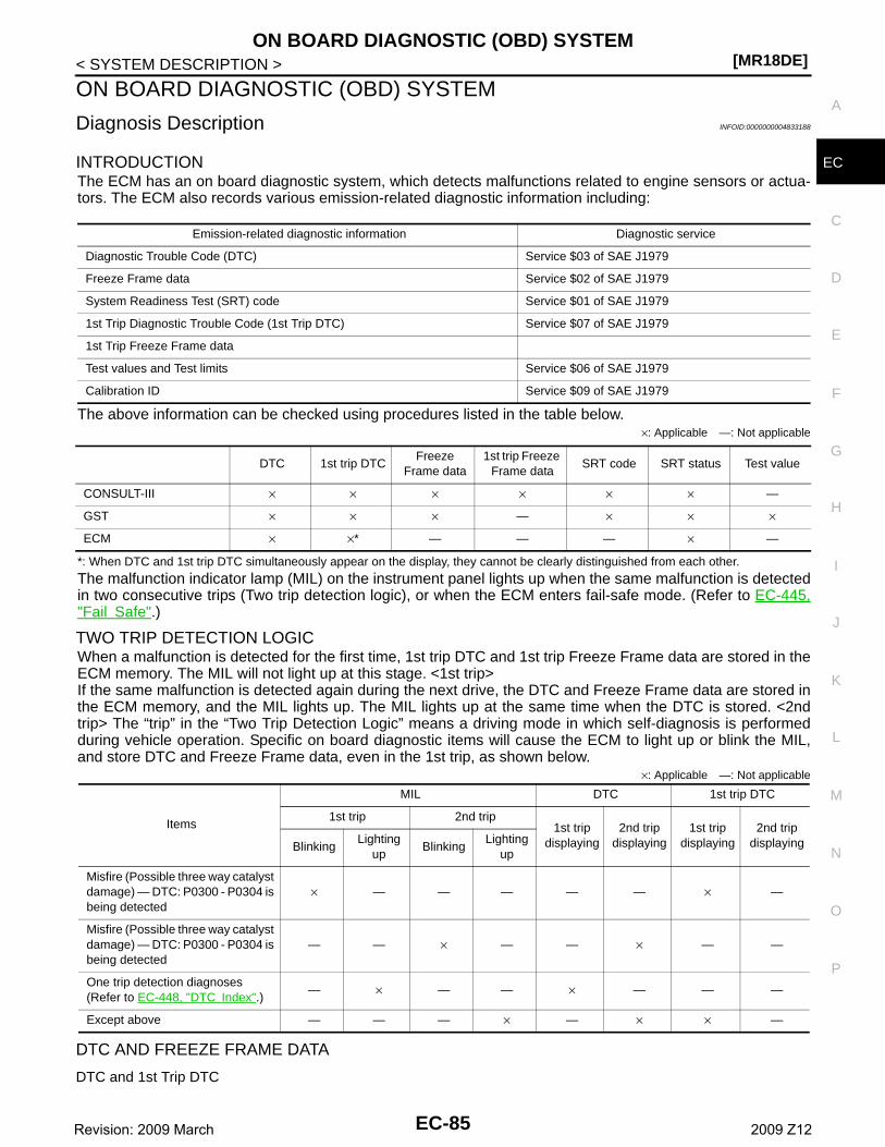
ON BOARD DIAGNOSTIC (OBD) SYSTEM[MR18DE]
C
D
E
F
G
H
I
J
K
L
M
A
C
N
P
O
< SYSTEM DESCRIPTION >
E
ON BOARD DIAGNOSTIC (OBD) SYSTEM
Diagnosis Description INFOID:0000000004833188
INTRODUCTIONThe ECM has an on board diagnostic system, which detects malfunctions related to engine sensors or actua-tors. The ECM also records various emission-related diagnostic information including:
The above information can be checked using procedures listed in the table below.×: Applicable —: Not applicable
*: When DTC and 1st trip DTC simultaneously appear on the display, they cannot be clearly distinguished from each other.
The malfunction indicator lamp (MIL) on the instrument panel lights up when the same malfunction is detectedin two consecutive trips (Two trip detection logic), or when the ECM enters fail-safe mode. (Refer to EC-445,"Fail Safe".)
TWO TRIP DETECTION LOGICWhen a malfunction is detected for the first time, 1st trip DTC and 1st trip Freeze Frame data are stored in theECM memory. The MIL will not light up at this stage. <1st trip>If the same malfunction is detected again during the next drive, the DTC and Freeze Frame data are stored inthe ECM memory, and the MIL lights up. The MIL lights up at the same time when the DTC is stored. <2ndtrip> The “trip” in the “Two Trip Detection Logic” means a driving mode in which self-diagnosis is performedduring vehicle operation. Specific on board diagnostic items will cause the ECM to light up or blink the MIL,and store DTC and Freeze Frame data, even in the 1st trip, as shown below.
×: Applicable —: Not applicable
DTC AND FREEZE FRAME DATA
DTC and 1st Trip DTC
Emission-related diagnostic information Diagnostic service
Diagnostic Trouble Code (DTC) Service $03 of SAE J1979
Freeze Frame data Service $02 of SAE J1979
System Readiness Test (SRT) code Service $01 of SAE J1979
1st Trip Diagnostic Trouble Code (1st Trip DTC) Service $07 of SAE J1979
1st Trip Freeze Frame data
Test values and Test limits Service $06 of SAE J1979
Calibration ID Service $09 of SAE J1979
DTC 1st trip DTCFreeze
Frame data1st trip Freeze
Frame dataSRT code SRT status Test value
CONSULT-III × × × × × × —
GST × × × — × × ×
ECM × ×* — — — × —
Items
MIL DTC 1st trip DTC
1st trip 2nd trip 1st trip
displaying2nd trip
displaying1st trip
displaying2nd trip
displayingBlinkingLighting
upBlinking
Lighting up
Misfire (Possible three way catalyst damage) — DTC: P0300 - P0304 is being detected
× — — — — — × —
Misfire (Possible three way catalyst damage) — DTC: P0300 - P0304 is being detected
— — × — — × — —
One trip detection diagnoses(Refer to EC-448, "DTC Index".)
— × — — × — — —
Except above — — — × — × × —
EC-85Revision: 2009 March 2009 Z12
[MR18DE]ON BOARD DIAGNOSTIC (OBD) SYSTEM
< SYSTEM DESCRIPTION >The 1st trip DTC (whose number is the same as the DTC number) is displayed for the latest self-diagnosticresult obtained. If the ECM memory was cleared previously, and the 1st trip DTC did not recur, the 1st trip DTCwill not be displayed.If a malfunction is detected during the 1st trip, the 1st trip DTC is stored in the ECM memory. The MIL will notlight up (two trip detection logic). If the same malfunction is not detected in the 2nd trip (meeting the requireddriving pattern), the 1st trip DTC is cleared from the ECM memory. If the same malfunction is detected in the2nd trip, both the 1st trip DTC and DTC are stored in the ECM memory and the MIL lights up. In other words,the DTC is stored in the ECM memory and the MIL lights up when the same malfunction occurs in two consec-utive trips. If a 1st trip DTC is stored and a non-diagnostic operation is performed between the 1st and 2ndtrips, only the 1st trip DTC will continue to be stored. For malfunctions that blink or light up the MIL during the1st trip, the DTC and 1st trip DTC are stored in the ECM memory.Procedures for clearing the DTC and the 1st trip DTC from the ECM memory are described in “How to EraseDTC and 1st Trip DTC”.For malfunctions in which 1st trip DTCs are displayed, refer to EC-448, "DTC Index". These items arerequired by legal regulations to continuously monitor the system/component. In addition, the items monitorednon-continuously are also displayed on CONSULT-III.1st trip DTC is specified in Service $07 of SAE J1979. 1st trip DTC detection occurs without lighting up the MILand therefore does not warn the driver of a malfunction. However, 1st trip DTC detection will not prevent thevehicle from being tested, for example during Inspection/Maintenance (I/M) tests.When a 1st trip DTC is detected, check, print out or write down and erase (1st trip) DTC and Freeze Framedata as specified in Work Flow procedure Step 2, refer to EC-8, "Work Flow". Then perform DTC CONFIRMA-TION PROCEDURE or Component Function Check to try to duplicate the malfunction. If the malfunction isduplicated, the item requires repair.
Freeze Frame Data and 1st Trip Freeze Frame DataThe ECM records the driving conditions such as fuel system status, calculated load value, engine coolant tem-perature, short-term fuel trim, long-term fuel trim, engine speed, vehicle speed, absolute throttle position, basefuel schedule and intake air temperature at the moment a malfunction is detected.Data which are stored in the ECM memory, along with the 1st trip DTC, are called 1st trip freeze frame data.The data, stored together with the DTC data, are called freeze frame data and displayed on CONSULT-III orGST. The 1st trip freeze frame data can only be displayed on the CONSULT-III screen, not on the GST.Only one set of freeze frame data (either 1st trip freeze frame data or freeze frame data) can be stored in theECM. 1st trip freeze frame data is stored in the ECM memory along with the 1st trip DTC. There is no priorityfor 1st trip freeze frame data and it is updated each time a different 1st trip DTC is detected. However, oncefreeze frame data (2nd trip detection/MIL on) is stored in the ECM memory, 1st trip freeze frame data is nolonger stored. Remember, only one set of freeze frame data can be stored in the ECM. The ECM has the fol-lowing priorities to update the data.
For example, the EGR malfunction (Priority: 2) was detected and the freeze frame data was stored in the 2ndtrip. After that when the misfire (Priority: 1) is detected in another trip, the freeze frame data will be updatedfrom the EGR malfunction to the misfire. The 1st trip freeze frame data is updated each time a different mal-function is detected. There is no priority for 1st trip freeze frame data. However, once freeze frame data isstored in the ECM memory, 1st trip freeze data is no longer stored (because only one freeze frame data or 1sttrip freeze frame data can be stored in the ECM). If freeze frame data is stored in the ECM memory and freezeframe data with the same priority occurs later, the first (original) freeze frame data remains unchanged in theECM memory.Both 1st trip freeze frame data and freeze frame data (along with the DTCs) are cleared when the ECM mem-ory is erased. Procedures for clearing the ECM memory are described in “How to Erase DTC and 1st TripDTC”.
How to Read DTC and 1st Trip DTCDTC and 1st trip DTC can be read by the following methods.
With CONSULT-IIICONSULT-III displays the DTC in “SELF DIAGNOSTIC RESULT” mode.Examples: P0340, P0850, P1148, etc.
Priority Items
1Freeze frame data Misfire — DTC: P0300 - P0304
Fuel Injection System Function — DTC: P0171, P0172
2 Except the above items (Includes CVT related items)
3 1st trip freeze frame data
EC-86Revision: 2009 March 2009 Z12
ON BOARD DIAGNOSTIC (OBD) SYSTEM[MR18DE]
C
D
E
F
G
H
I
J
K
L
M
A
C
N
P
O
< SYSTEM DESCRIPTION >
E
These DTCs are prescribed by SAE J2012.(CONSULT-III also displays the malfunctioning component or system.)Time data indicates how many times the vehicle was driven after the last detection of a DTC.If the DTC is being detected currently, the time data will be [0].If a 1st trip DTC is stored in the ECM, the time data will be [1t].
With GSTGST (Generic Scan Tool) displays the DTC in Diagnostic Service $03.Examples: P0340, P0850, P1148, etc.These DTCs are prescribed by SAE J2012.
No ToolsThe number of blinks of the MIL in the Diagnostic Test Mode II (Self-Diagnostic Results) indicates the DTC.Example: 0340, 0850, 1148, etc.These DTCs are controlled by NISSAN.NOTE:• 1st trip DTC No. is the same as DTC No.• Output of a DTC indicates a malfunction. However, GST and the Diagnostic Test Mode II do not indi-
cate whether the malfunction is still occurring or has occurred in the past and has returned to nor-mal. CONSULT-III can identify malfunction status. Therefore, using CONSULT-III (if available) isrecommended.
How to Erase DTC and 1st Trip DTC
With CONSULT-IIINOTE:• If the ignition switch stays ON after repair work, be sure to turn ignition switch OFF once. Wait at
least 10 seconds and then turn it ON (engine stopped) again.• If the DTC is not for CVT related items (EC-448, "DTC Index"), skip step 1.1. Erase DTC in TCM. Refer to TM-91, "Diagnosis Description".2. Select “ENGINE” with CONSULT-III.3. Select “SELF DIAGNOSTIC RESULT”.4. Touch “ERASE”. (DTC in ECM will be erased.)
With GSTNOTE:If the ignition switch stays ON after repair work, be sure to turn ignition switch OFF once. Wait at least10 seconds and then turn it ON (engine stopped) again.1. Select Service $04 with GST (Generic Scan Tool).
No ToolsNOTE:If the ignition switch stays ON after repair work, be sure to turn ignition switch OFF once. Wait at least10 seconds and then turn it ON (engine stopped) again.1. Erase DTC in ECM. Refer to HOW TO ERASE DIAGNOSTIC TEST MODE II (SELF-DIAGNOSTIC
RESULTS).• If the battery is disconnected, the emission-related diagnostic information will be cleared within 24
hours.• The following data are cleared when the ECM memory is erased.- Diagnostic trouble codes- 1st trip diagnostic trouble codes- Freeze frame data- 1st trip freeze frame data- System readiness test (SRT) codes- Test valuesActual work procedures are explained using a DTC as an example. Be careful so that not only the DTC, but allof the data listed above, are cleared from the ECM memory during work procedures.
SYSTEM READINESS TEST (SRT) CODESystem Readiness Test (SRT) code is specified in Service $01 of SAE J1979.As part of an enhanced emissions test for Inspection & Maintenance (I/M), certain states require the status ofSRT be used to indicate whether the ECM has completed self-diagnosis of major emission systems and com-ponents. Completion must be verified in order for the emissions inspection to proceed.If a vehicle is rejected for a State emissions inspection due to one or more SRT items indicating “INCMP”, usethe information in this Service Manual to set the SRT to “CMPLT”.
EC-87Revision: 2009 March 2009 Z12
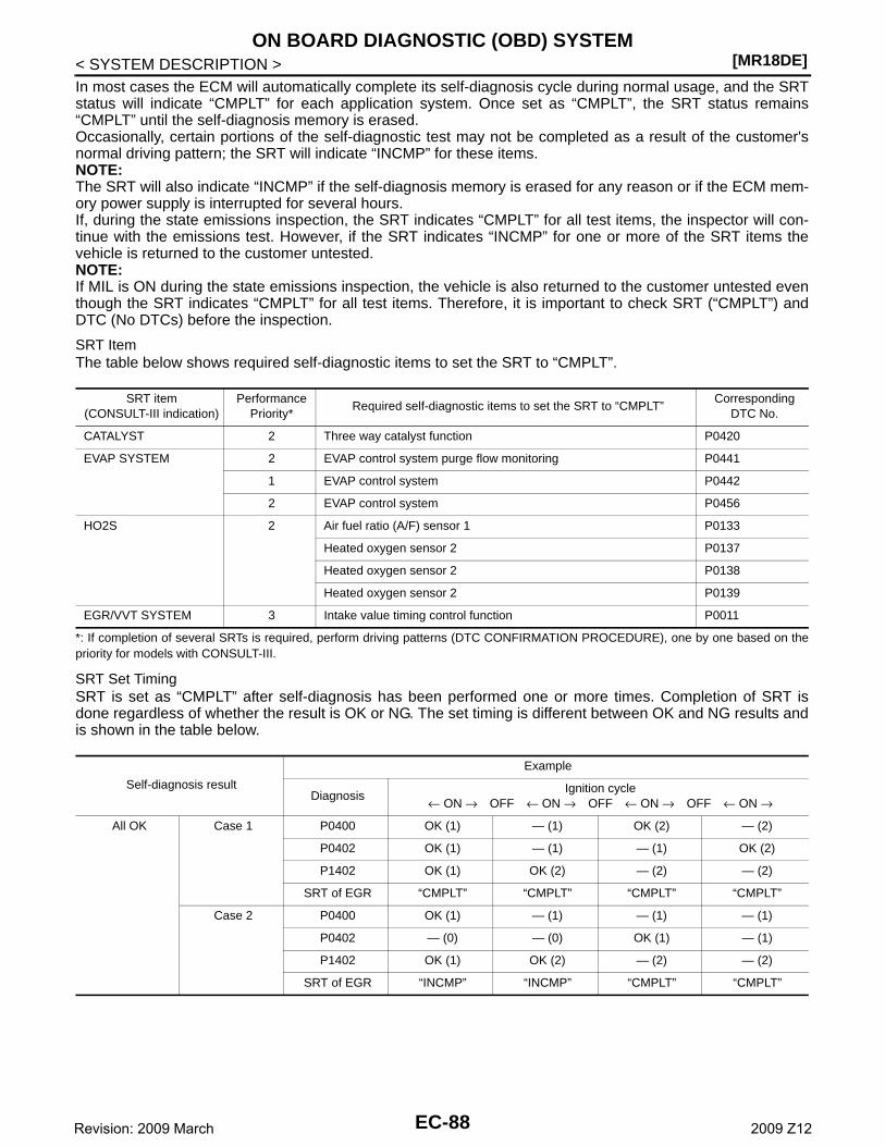
[MR18DE]ON BOARD DIAGNOSTIC (OBD) SYSTEM
< SYSTEM DESCRIPTION >In most cases the ECM will automatically complete its self-diagnosis cycle during normal usage, and the SRTstatus will indicate “CMPLT” for each application system. Once set as “CMPLT”, the SRT status remains“CMPLT” until the self-diagnosis memory is erased.Occasionally, certain portions of the self-diagnostic test may not be completed as a result of the customer'snormal driving pattern; the SRT will indicate “INCMP” for these items.NOTE:The SRT will also indicate “INCMP” if the self-diagnosis memory is erased for any reason or if the ECM mem-ory power supply is interrupted for several hours.If, during the state emissions inspection, the SRT indicates “CMPLT” for all test items, the inspector will con-tinue with the emissions test. However, if the SRT indicates “INCMP” for one or more of the SRT items thevehicle is returned to the customer untested.NOTE:If MIL is ON during the state emissions inspection, the vehicle is also returned to the customer untested eventhough the SRT indicates “CMPLT” for all test items. Therefore, it is important to check SRT (“CMPLT”) andDTC (No DTCs) before the inspection.
SRT ItemThe table below shows required self-diagnostic items to set the SRT to “CMPLT”.
*: If completion of several SRTs is required, perform driving patterns (DTC CONFIRMATION PROCEDURE), one by one based on thepriority for models with CONSULT-III.
SRT Set TimingSRT is set as “CMPLT” after self-diagnosis has been performed one or more times. Completion of SRT isdone regardless of whether the result is OK or NG. The set timing is different between OK and NG results andis shown in the table below.
SRT item(CONSULT-III indication)
Performance Priority*
Required self-diagnostic items to set the SRT to “CMPLT”Corresponding
DTC No.
CATALYST 2 Three way catalyst function P0420
EVAP SYSTEM 2 EVAP control system purge flow monitoring P0441
1 EVAP control system P0442
2 EVAP control system P0456
HO2S 2 Air fuel ratio (A/F) sensor 1 P0133
Heated oxygen sensor 2 P0137
Heated oxygen sensor 2 P0138
Heated oxygen sensor 2 P0139
EGR/VVT SYSTEM 3 Intake value timing control function P0011
Self-diagnosis result
Example
DiagnosisIgnition cycle
← ON → OFF ← ON → OFF ← ON → OFF ← ON →
All OK Case 1 P0400 OK (1) — (1) OK (2) — (2)
P0402 OK (1) — (1) — (1) OK (2)
P1402 OK (1) OK (2) — (2) — (2)
SRT of EGR “CMPLT” “CMPLT” “CMPLT” “CMPLT”
Case 2 P0400 OK (1) — (1) — (1) — (1)
P0402 — (0) — (0) OK (1) — (1)
P1402 OK (1) OK (2) — (2) — (2)
SRT of EGR “INCMP” “INCMP” “CMPLT” “CMPLT”
EC-88Revision: 2009 March 2009 Z12
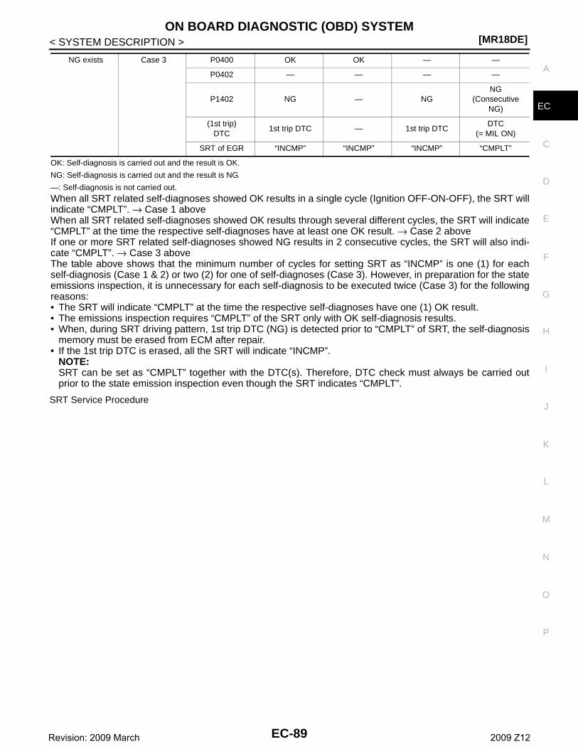
ON BOARD DIAGNOSTIC (OBD) SYSTEM[MR18DE]
C
D
E
F
G
H
I
J
K
L
M
A
C
N
P
O
< SYSTEM DESCRIPTION >
E
OK: Self-diagnosis is carried out and the result is OK.
NG: Self-diagnosis is carried out and the result is NG.
—: Self-diagnosis is not carried out.
When all SRT related self-diagnoses showed OK results in a single cycle (Ignition OFF-ON-OFF), the SRT willindicate “CMPLT”. → Case 1 aboveWhen all SRT related self-diagnoses showed OK results through several different cycles, the SRT will indicate“CMPLT” at the time the respective self-diagnoses have at least one OK result. → Case 2 aboveIf one or more SRT related self-diagnoses showed NG results in 2 consecutive cycles, the SRT will also indi-cate “CMPLT”. → Case 3 aboveThe table above shows that the minimum number of cycles for setting SRT as “INCMP” is one (1) for eachself-diagnosis (Case 1 & 2) or two (2) for one of self-diagnoses (Case 3). However, in preparation for the stateemissions inspection, it is unnecessary for each self-diagnosis to be executed twice (Case 3) for the followingreasons:• The SRT will indicate “CMPLT” at the time the respective self-diagnoses have one (1) OK result.• The emissions inspection requires “CMPLT” of the SRT only with OK self-diagnosis results.• When, during SRT driving pattern, 1st trip DTC (NG) is detected prior to “CMPLT” of SRT, the self-diagnosis
memory must be erased from ECM after repair.• If the 1st trip DTC is erased, all the SRT will indicate “INCMP”.
NOTE:SRT can be set as “CMPLT” together with the DTC(s). Therefore, DTC check must always be carried outprior to the state emission inspection even though the SRT indicates “CMPLT”.
SRT Service Procedure
NG exists Case 3 P0400 OK OK — —
P0402 — — — —
P1402 NG — NGNG
(Consecutive NG)
(1st trip)DTC
1st trip DTC — 1st trip DTCDTC
(= MIL ON)
SRT of EGR “INCMP” “INCMP” “INCMP” “CMPLT”
EC-89Revision: 2009 March 2009 Z12
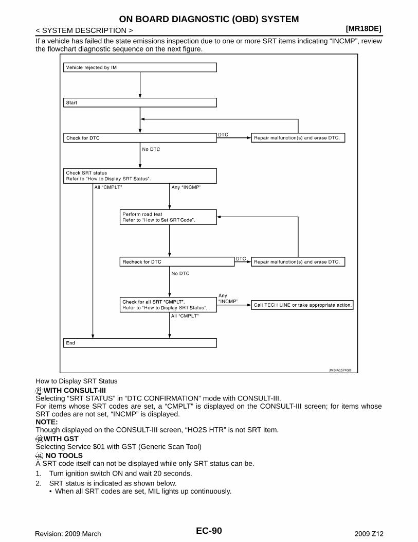
[MR18DE]ON BOARD DIAGNOSTIC (OBD) SYSTEM
< SYSTEM DESCRIPTION >If a vehicle has failed the state emissions inspection due to one or more SRT items indicating “INCMP”, reviewthe flowchart diagnostic sequence on the next figure.
How to Display SRT StatusWITH CONSULT-III
Selecting “SRT STATUS” in “DTC CONFIRMATION” mode with CONSULT-III.For items whose SRT codes are set, a “CMPLT” is displayed on the CONSULT-III screen; for items whoseSRT codes are not set, “INCMP” is displayed.NOTE:Though displayed on the CONSULT-III screen, “HO2S HTR” is not SRT item.
WITH GSTSelecting Service $01 with GST (Generic Scan Tool)
NO TOOLSA SRT code itself can not be displayed while only SRT status can be.1. Turn ignition switch ON and wait 20 seconds.2. SRT status is indicated as shown below.
• When all SRT codes are set, MIL lights up continuously.
JMBIA1574GB
EC-90Revision: 2009 March 2009 Z12
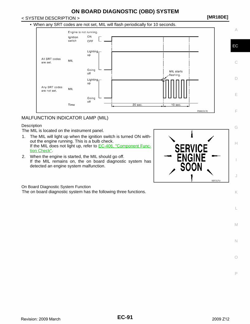
ON BOARD DIAGNOSTIC (OBD) SYSTEM[MR18DE]
C
D
E
F
G
H
I
J
K
L
M
A
C
N
P
O
< SYSTEM DESCRIPTION >
E
• When any SRT codes are not set, MIL will flash periodically for 10 seconds.
MALFUNCTION INDICATOR LAMP (MIL)
DescriptionThe MIL is located on the instrument panel.1. The MIL will light up when the ignition switch is turned ON with-
out the engine running. This is a bulb check.If the MIL does not light up, refer to EC-406, "Component Func-tion Check".
2. When the engine is started, the MIL should go off.If the MIL remains on, the on board diagnostic system hasdetected an engine system malfunction.
On Board Diagnostic System FunctionThe on board diagnostic system has the following three functions.
PBIB2317E
SEF217U
EC-91Revision: 2009 March 2009 Z12
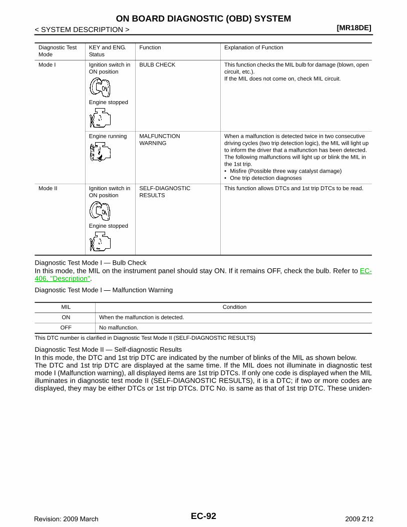
[MR18DE]ON BOARD DIAGNOSTIC (OBD) SYSTEM
< SYSTEM DESCRIPTION >
Diagnostic Test Mode I — Bulb CheckIn this mode, the MIL on the instrument panel should stay ON. If it remains OFF, check the bulb. Refer to EC-406, "Description".
Diagnostic Test Mode I — Malfunction Warning
This DTC number is clarified in Diagnostic Test Mode II (SELF-DIAGNOSTIC RESULTS)
Diagnostic Test Mode II — Self-diagnostic ResultsIn this mode, the DTC and 1st trip DTC are indicated by the number of blinks of the MIL as shown below.The DTC and 1st trip DTC are displayed at the same time. If the MIL does not illuminate in diagnostic testmode I (Malfunction warning), all displayed items are 1st trip DTCs. If only one code is displayed when the MILilluminates in diagnostic test mode II (SELF-DIAGNOSTIC RESULTS), it is a DTC; if two or more codes aredisplayed, they may be either DTCs or 1st trip DTCs. DTC No. is same as that of 1st trip DTC. These uniden-
Diagnostic Test Mode
KEY and ENG. Status
Function Explanation of Function
Mode I Ignition switch in ON position
Engine stopped
BULB CHECK This function checks the MIL bulb for damage (blown, open circuit, etc.).If the MIL does not come on, check MIL circuit.
Engine running MALFUNCTIONWARNING
When a malfunction is detected twice in two consecutive driving cycles (two trip detection logic), the MIL will light up to inform the driver that a malfunction has been detected.The following malfunctions will light up or blink the MIL in the 1st trip.• Misfire (Possible three way catalyst damage)• One trip detection diagnoses
Mode II Ignition switch in ON position
Engine stopped
SELF-DIAGNOSTICRESULTS
This function allows DTCs and 1st trip DTCs to be read.
MIL Condition
ON When the malfunction is detected.
OFF No malfunction.
EC-92Revision: 2009 March 2009 Z12
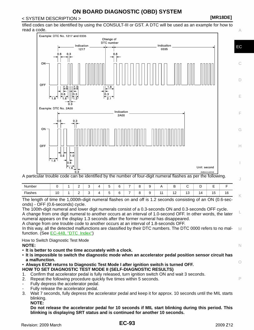
ON BOARD DIAGNOSTIC (OBD) SYSTEM[MR18DE]
C
D
E
F
G
H
I
J
K
L
M
A
C
N
P
O
< SYSTEM DESCRIPTION >
E
tified codes can be identified by using the CONSULT-III or GST. A DTC will be used as an example for how toread a code.
A particular trouble code can be identified by the number of four-digit numeral flashes as per the following.
The length of time the 1,000th-digit numeral flashes on and off is 1.2 seconds consisting of an ON (0.6-sec-onds) - OFF (0.6-seconds) cycle.The 100th-digit numeral and lower digit numerals consist of a 0.3-seconds ON and 0.3-seconds OFF cycle.A change from one digit numeral to another occurs at an interval of 1.0-second OFF. In other words, the laternumeral appears on the display 1.3 seconds after the former numeral has disappeared.A change from one trouble code to another occurs at an interval of 1.8-seconds OFF.In this way, all the detected malfunctions are classified by their DTC numbers. The DTC 0000 refers to no mal-function. (See EC-448, "DTC Index")
How to Switch Diagnostic Test ModeNOTE:• It is better to count the time accurately with a clock.• It is impossible to switch the diagnostic mode when an accelerator pedal position sensor circuit has
a malfunction.• Always ECM returns to Diagnostic Test Mode I after ignition switch is turned OFF.HOW TO SET DIAGNOSTIC TEST MODE II (SELF-DIAGNOSTIC RESULTS)1. Confirm that accelerator pedal is fully released, turn ignition switch ON and wait 3 seconds.2. Repeat the following procedure quickly five times within 5 seconds.- Fully depress the accelerator pedal.- Fully release the accelerator pedal.3. Wait 7 seconds, fully depress the accelerator pedal and keep it for approx. 10 seconds until the MIL starts
blinking.NOTE:Do not release the accelerator pedal for 10 seconds if MIL start blinking during this period. Thisblinking is displaying SRT status and is continued for another 10 seconds.
JMBIA1140GB
Number 0 1 2 3 4 5 6 7 8 9 A B C D E F
Flashes 10 1 2 3 4 5 6 7 8 9 11 12 13 14 15 16
EC-93Revision: 2009 March 2009 Z12
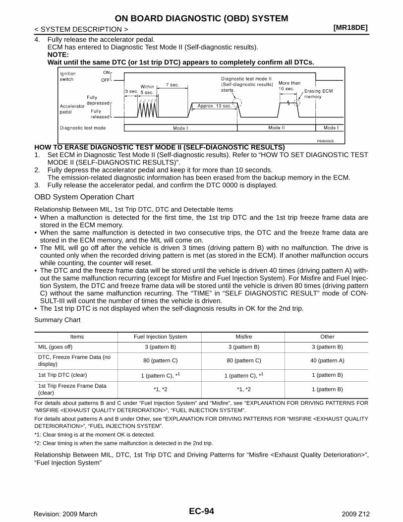
[MR18DE]ON BOARD DIAGNOSTIC (OBD) SYSTEM
< SYSTEM DESCRIPTION >4. Fully release the accelerator pedal.
ECM has entered to Diagnostic Test Mode II (Self-diagnostic results).NOTE:Wait until the same DTC (or 1st trip DTC) appears to completely confirm all DTCs.
HOW TO ERASE DIAGNOSTIC TEST MODE II (SELF-DIAGNOSTIC RESULTS)1. Set ECM in Diagnostic Test Mode II (Self-diagnostic results). Refer to “HOW TO SET DIAGNOSTIC TEST
MODE II (SELF-DIAGNOSTIC RESULTS)”.2. Fully depress the accelerator pedal and keep it for more than 10 seconds.
The emission-related diagnostic information has been erased from the backup memory in the ECM.3. Fully release the accelerator pedal, and confirm the DTC 0000 is displayed.
OBD System Operation Chart
Relationship Between MIL, 1st Trip DTC, DTC and Detectable Items• When a malfunction is detected for the first time, the 1st trip DTC and the 1st trip freeze frame data are
stored in the ECM memory.• When the same malfunction is detected in two consecutive trips, the DTC and the freeze frame data are
stored in the ECM memory, and the MIL will come on.• The MIL will go off after the vehicle is driven 3 times (driving pattern B) with no malfunction. The drive is
counted only when the recorded driving pattern is met (as stored in the ECM). If another malfunction occurswhile counting, the counter will reset.
• The DTC and the freeze frame data will be stored until the vehicle is driven 40 times (driving pattern A) with-out the same malfunction recurring (except for Misfire and Fuel Injection System). For Misfire and Fuel Injec-tion System, the DTC and freeze frame data will be stored until the vehicle is driven 80 times (driving patternC) without the same malfunction recurring. The “TIME” in “SELF DIAGNOSTIC RESULT” mode of CON-SULT-III will count the number of times the vehicle is driven.
• The 1st trip DTC is not displayed when the self-diagnosis results in OK for the 2nd trip.
Summary Chart
For details about patterns B and C under “Fuel Injection System” and “Misfire”, see “EXPLANATION FOR DRIVING PATTERNS FOR“MISFIRE <EXHAUST QUALITY DETERIORATION>”, “FUEL INJECTION SYSTEM”.
For details about patterns A and B under Other, see “EXPLANATION FOR DRIVING PATTERNS FOR “MISFIRE <EXHAUST QUALITYDETERIORATION>”, “FUEL INJECTION SYSTEM”.
*1: Clear timing is at the moment OK is detected.
*2: Clear timing is when the same malfunction is detected in the 2nd trip.
Relationship Between MIL, DTC, 1st Trip DTC and Driving Patterns for “Misfire <Exhaust Quality Deterioration>”,“Fuel Injection System”
PBIB0092E
Items Fuel Injection System Misfire Other
MIL (goes off) 3 (pattern B) 3 (pattern B) 3 (pattern B)
DTC, Freeze Frame Data (no display)
80 (pattern C) 80 (pattern C) 40 (pattern A)
1st Trip DTC (clear) 1 (pattern C), *1 1 (pattern C), *1 1 (pattern B)
1st Trip Freeze Frame Data (clear)
*1, *2 *1, *2 1 (pattern B)
EC-94Revision: 2009 March 2009 Z12
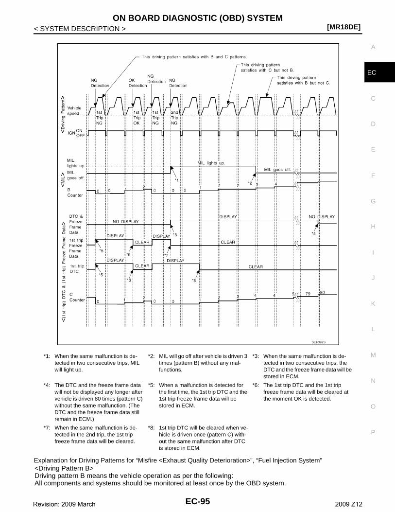
ON BOARD DIAGNOSTIC (OBD) SYSTEM[MR18DE]
C
D
E
F
G
H
I
J
K
L
M
A
C
N
P
O
< SYSTEM DESCRIPTION >
E
Explanation for Driving Patterns for “Misfire <Exhaust Quality Deterioration>”, “Fuel Injection System”<Driving Pattern B>Driving pattern B means the vehicle operation as per the following:All components and systems should be monitored at least once by the OBD system.
*1: When the same malfunction is de-tected in two consecutive trips, MIL will light up.
*2: MIL will go off after vehicle is driven 3 times (pattern B) without any mal-functions.
*3: When the same malfunction is de-tected in two consecutive trips, the DTC and the freeze frame data will be stored in ECM.
*4: The DTC and the freeze frame data will not be displayed any longer after vehicle is driven 80 times (pattern C) without the same malfunction. (The DTC and the freeze frame data still remain in ECM.)
*5: When a malfunction is detected for the first time, the 1st trip DTC and the 1st trip freeze frame data will be stored in ECM.
*6: The 1st trip DTC and the 1st trip freeze frame data will be cleared at the moment OK is detected.
*7: When the same malfunction is de-tected in the 2nd trip, the 1st trip freeze frame data will be cleared.
*8: 1st trip DTC will be cleared when ve-hicle is driven once (pattern C) with-out the same malfunction after DTC is stored in ECM.
SEF392S
EC-95Revision: 2009 March 2009 Z12
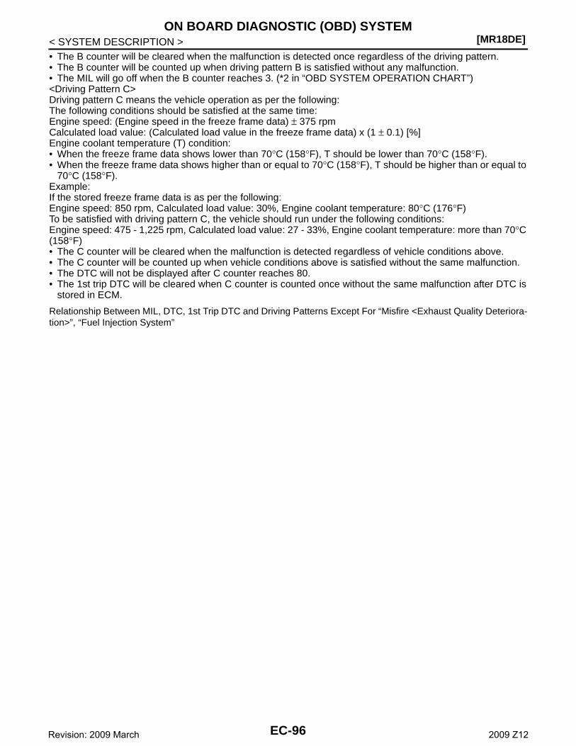
[MR18DE]ON BOARD DIAGNOSTIC (OBD) SYSTEM
< SYSTEM DESCRIPTION >• The B counter will be cleared when the malfunction is detected once regardless of the driving pattern.• The B counter will be counted up when driving pattern B is satisfied without any malfunction.• The MIL will go off when the B counter reaches 3. (*2 in “OBD SYSTEM OPERATION CHART”)<Driving Pattern C>Driving pattern C means the vehicle operation as per the following:The following conditions should be satisfied at the same time:Engine speed: (Engine speed in the freeze frame data) ± 375 rpmCalculated load value: (Calculated load value in the freeze frame data) x (1 ± 0.1) [%]Engine coolant temperature (T) condition:• When the freeze frame data shows lower than 70°C (158°F), T should be lower than 70°C (158°F).• When the freeze frame data shows higher than or equal to 70°C (158°F), T should be higher than or equal to
70°C (158°F).Example:If the stored freeze frame data is as per the following:Engine speed: 850 rpm, Calculated load value: 30%, Engine coolant temperature: 80°C (176°F)To be satisfied with driving pattern C, the vehicle should run under the following conditions:Engine speed: 475 - 1,225 rpm, Calculated load value: 27 - 33%, Engine coolant temperature: more than 70°C(158°F)• The C counter will be cleared when the malfunction is detected regardless of vehicle conditions above.• The C counter will be counted up when vehicle conditions above is satisfied without the same malfunction.• The DTC will not be displayed after C counter reaches 80.• The 1st trip DTC will be cleared when C counter is counted once without the same malfunction after DTC is
stored in ECM.
Relationship Between MIL, DTC, 1st Trip DTC and Driving Patterns Except For “Misfire <Exhaust Quality Deteriora-tion>”, “Fuel Injection System”
EC-96Revision: 2009 March 2009 Z12
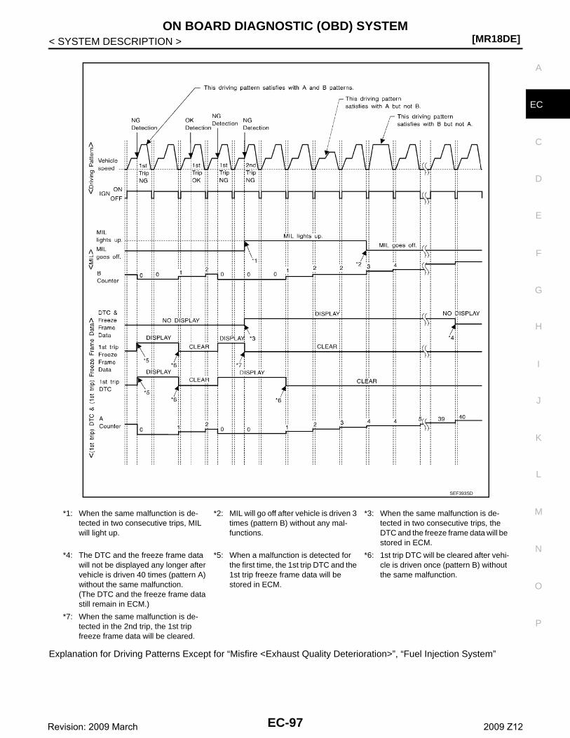
ON BOARD DIAGNOSTIC (OBD) SYSTEM[MR18DE]
C
D
E
F
G
H
I
J
K
L
M
A
C
N
P
O
< SYSTEM DESCRIPTION >
E
Explanation for Driving Patterns Except for “Misfire <Exhaust Quality Deterioration>”, “Fuel Injection System”
*1: When the same malfunction is de-tected in two consecutive trips, MIL will light up.
*2: MIL will go off after vehicle is driven 3 times (pattern B) without any mal-functions.
*3: When the same malfunction is de-tected in two consecutive trips, the DTC and the freeze frame data will be stored in ECM.
*4: The DTC and the freeze frame data will not be displayed any longer after vehicle is driven 40 times (pattern A) without the same malfunction.(The DTC and the freeze frame data still remain in ECM.)
*5: When a malfunction is detected for the first time, the 1st trip DTC and the 1st trip freeze frame data will be stored in ECM.
*6: 1st trip DTC will be cleared after vehi-cle is driven once (pattern B) without the same malfunction.
*7: When the same malfunction is de-tected in the 2nd trip, the 1st trip freeze frame data will be cleared.
SEF393SD
EC-97Revision: 2009 March 2009 Z12
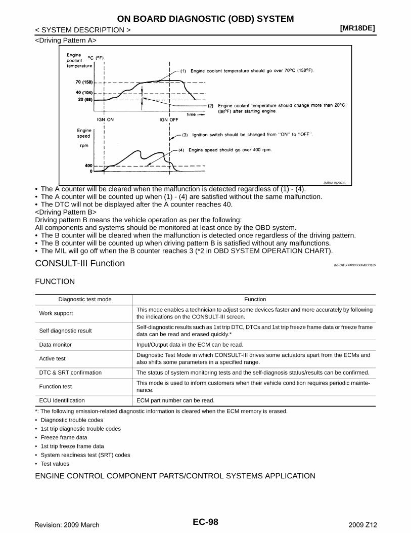
[MR18DE]ON BOARD DIAGNOSTIC (OBD) SYSTEM
< SYSTEM DESCRIPTION ><Driving Pattern A>
• The A counter will be cleared when the malfunction is detected regardless of (1) - (4).• The A counter will be counted up when (1) - (4) are satisfied without the same malfunction.• The DTC will not be displayed after the A counter reaches 40.<Driving Pattern B>Driving pattern B means the vehicle operation as per the following:All components and systems should be monitored at least once by the OBD system.• The B counter will be cleared when the malfunction is detected once regardless of the driving pattern.• The B counter will be counted up when driving pattern B is satisfied without any malfunctions.• The MIL will go off when the B counter reaches 3 (*2 in OBD SYSTEM OPERATION CHART).
CONSULT-III Function INFOID:0000000004833189
FUNCTION
*: The following emission-related diagnostic information is cleared when the ECM memory is erased.
• Diagnostic trouble codes
• 1st trip diagnostic trouble codes
• Freeze frame data
• 1st trip freeze frame data
• System readiness test (SRT) codes
• Test values
ENGINE CONTROL COMPONENT PARTS/CONTROL SYSTEMS APPLICATION
JMBIA1920GB
Diagnostic test mode Function
Work supportThis mode enables a technician to adjust some devices faster and more accurately by following the indications on the CONSULT-III screen.
Self diagnostic resultSelf-diagnostic results such as 1st trip DTC, DTCs and 1st trip freeze frame data or freeze frame data can be read and erased quickly.*
Data monitor Input/Output data in the ECM can be read.
Active testDiagnostic Test Mode in which CONSULT-III drives some actuators apart from the ECMs and also shifts some parameters in a specified range.
DTC & SRT confirmation The status of system monitoring tests and the self-diagnosis status/results can be confirmed.
Function testThis mode is used to inform customers when their vehicle condition requires periodic mainte-nance.
ECU Identification ECM part number can be read.
EC-98Revision: 2009 March 2009 Z12
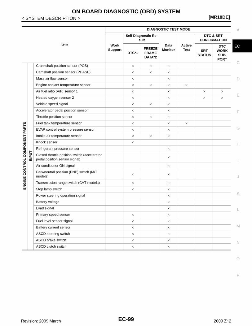
ON BOARD DIAGNOSTIC (OBD) SYSTEM[MR18DE]
C
D
E
F
G
H
I
J
K
L
M
A
C
N
P
O
< SYSTEM DESCRIPTION >
EItem
DIAGNOSTIC TEST MODE
Work Support
Self Diagnostic Re-sult
Data Monitor
Active Test
DTC & SRTCONFIRMATION
DTC*1FREEZE FRAME DATA*2
SRT STATUS
DTC WORK SUP-PORT
EN
GIN
E C
ON
TR
OL
CO
MP
ON
EN
T P
AR
TS
INP
UT
Crankshaft position sensor (POS) × × ×
Camshaft position sensor (PHASE) × × ×
Mass air flow sensor × ×
Engine coolant temperature sensor × × × ×
Air fuel ratio (A/F) sensor 1 × × × ×
Heated oxygen sensor 2 × × × ×
Vehicle speed signal × × ×
Accelerator pedal position sensor × ×
Throttle position sensor × × ×
Fuel tank temperature sensor × × ×
EVAP control system pressure sensor × ×
Intake air temperature sensor × × ×
Knock sensor ×
Refrigerant pressure sensor ×
Closed throttle position switch (accelerator pedal position sensor signal)
×
Air conditioner ON signal ×
Park/neutral position (PNP) switch (M/T models)
× ×
Transmission range switch (CVT models) × ×
Stop lamp switch × ×
Power steering operation signal ×
Battery voltage ×
Load signal ×
Primary speed sensor × ×
Fuel level sensor signal × ×
Battery current sensor × ×
ASCD steering switch × ×
ASCD brake switch × ×
ASCD clutch switch × ×
EC-99Revision: 2009 March 2009 Z12
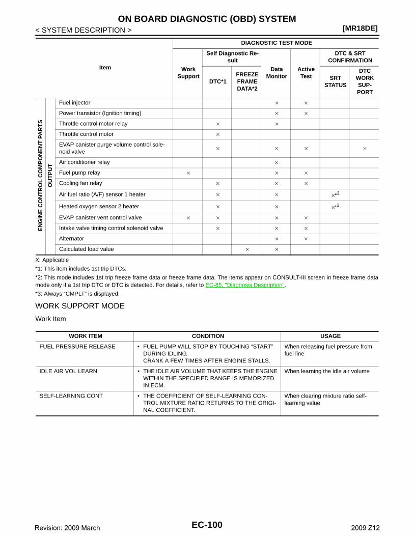
[MR18DE]ON BOARD DIAGNOSTIC (OBD) SYSTEM
< SYSTEM DESCRIPTION >
X: Applicable
*1: This item includes 1st trip DTCs.
*2: This mode includes 1st trip freeze frame data or freeze frame data. The items appear on CONSULT-III screen in freeze frame datamode only if a 1st trip DTC or DTC is detected. For details, refer to EC-85, "Diagnosis Description".
*3: Always “CMPLT” is displayed.
WORK SUPPORT MODE
Work Item
EN
GIN
E C
ON
TR
OL
CO
MP
ON
EN
T P
AR
TS
OU
TP
UT
Fuel injector × ×
Power transistor (Ignition timing) × ×
Throttle control motor relay × ×
Throttle control motor ×
EVAP canister purge volume control sole-noid valve
× × × ×
Air conditioner relay ×
Fuel pump relay × × ×
Cooling fan relay × × ×
Air fuel ratio (A/F) sensor 1 heater × × ×*3
Heated oxygen sensor 2 heater × × ×*3
EVAP canister vent control valve × × × ×
Intake valve timing control solenoid valve × × ×
Alternator × ×
Calculated load value × ×
Item
DIAGNOSTIC TEST MODE
Work Support
Self Diagnostic Re-sult
Data Monitor
Active Test
DTC & SRTCONFIRMATION
DTC*1FREEZE FRAME DATA*2
SRT STATUS
DTC WORK SUP-PORT
WORK ITEM CONDITION USAGE
FUEL PRESSURE RELEASE • FUEL PUMP WILL STOP BY TOUCHING “START” DURING IDLING.CRANK A FEW TIMES AFTER ENGINE STALLS.
When releasing fuel pressure from fuel line
IDLE AIR VOL LEARN • THE IDLE AIR VOLUME THAT KEEPS THE ENGINE WITHIN THE SPECIFIED RANGE IS MEMORIZED IN ECM.
When learning the idle air volume
SELF-LEARNING CONT • THE COEFFICIENT OF SELF-LEARNING CON-TROL MIXTURE RATIO RETURNS TO THE ORIGI-NAL COEFFICIENT.
When clearing mixture ratio self-learning value
EC-100Revision: 2009 March 2009 Z12
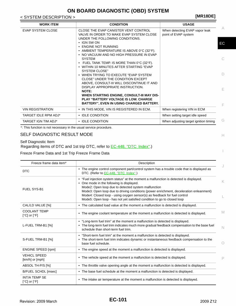
ON BOARD DIAGNOSTIC (OBD) SYSTEM[MR18DE]
C
D
E
F
G
H
I
J
K
L
M
A
C
N
P
O
< SYSTEM DESCRIPTION >
E
*: This function is not necessary in the usual service procedure.
SELF DIAGNOSTIC RESULT MODE
Self Diagnostic ItemRegarding items of DTC and 1st trip DTC, refer to EC-448, "DTC Index".)
Freeze Frame Data and 1st Trip Freeze Frame Data
EVAP SYSTEM CLOSE CLOSE THE EVAP CANISTER VENT CONTROL VALVE IN ORDER TO MAKE EVAP SYSTEM CLOSE UNDER THE FOLLOWING CONDITIONS.• IGN SW ON• ENGINE NOT RUNNING• AMBIENT TEMPERATURE IS ABOVE 0°C (32°F).• NO VACUUM AND NO HIGH PRESSURE IN EVAP
SYSTEM• FUEL TANK TEMP. IS MORE THAN 0°C (32°F).• WITHIN 10 MINUTES AFTER STARTING “EVAP
SYSTEM CLOSE”• WHEN TRYING TO EXECUTE “EVAP SYSTEM
CLOSE” UNDER THE CONDITION EXCEPT ABOVE, CONSULT-III WILL DISCONTINUE IT AND DISPLAY APPROPRIATE INSTRUCTION.NOTE:WHEN STARTING ENGINE, CONSULT-III MAY DIS-PLAY “BATTERY VOLTAGE IS LOW. CHARGE BATTERY”, EVEN IN USING CHARGED BATTERY.
When detecting EVAP vapor leak point of EVAP system
VIN REGISTRATION • IN THIS MODE, VIN IS REGISTERED IN ECM. When registering VIN in ECM
TARGET IDLE RPM ADJ* • IDLE CONDITION When setting target idle speed
TARGET IGN TIM ADJ* • IDLE CONDITION When adjusting target ignition timing
WORK ITEM CONDITION USAGE
Freeze frame data item* Description
DTC• The engine control component part/control system has a trouble code that is displayed as
DTC. (Refer to EC-448, "DTC Index".)
FUEL SYS-B1
• “Fuel injection system status” at the moment a malfunction is detected is displayed.• One mode in the following is displayed.
Mode2: Open loop due to detected system malfunctionMode3: Open loop due to driving conditions (power enrichment, deceleration enleanment)Mode4: Closed loop - using oxygen sensor(s) as feedback for fuel controlMode5: Open loop - has not yet satisfied condition to go to closed loop
CAL/LD VALUE [%] • The calculated load value at the moment a malfunction is detected is displayed.
COOLANT TEMP[°C] or [°F]
• The engine coolant temperature at the moment a malfunction is detected is displayed.
L-FUEL TRM-B1 [%]• “Long-term fuel trim” at the moment a malfunction is detected is displayed.• The long-term fuel trim indicates much more gradual feedback compensation to the base fuel
schedule than short-term fuel trim.
S-FUEL TRM-B1 [%]• “Short-term fuel trim” at the moment a malfunction is detected is displayed.• The short-term fuel trim indicates dynamic or instantaneous feedback compensation to the
base fuel schedule.
ENGINE SPEED [rpm] • The engine speed at the moment a malfunction is detected is displayed.
VEHICL SPEED[km/h] or [mph]
• The vehicle speed at the moment a malfunction is detected is displayed.
ABSOL TH·P/S [%] • The throttle valve opening angle at the moment a malfunction is detected is displayed.
B/FUEL SCHDL [msec] • The base fuel schedule at the moment a malfunction is detected is displayed.
INT/A TEMP SE[°C] or [°F]
• The intake air temperature at the moment a malfunction is detected is displayed.
EC-101Revision: 2009 March 2009 Z12
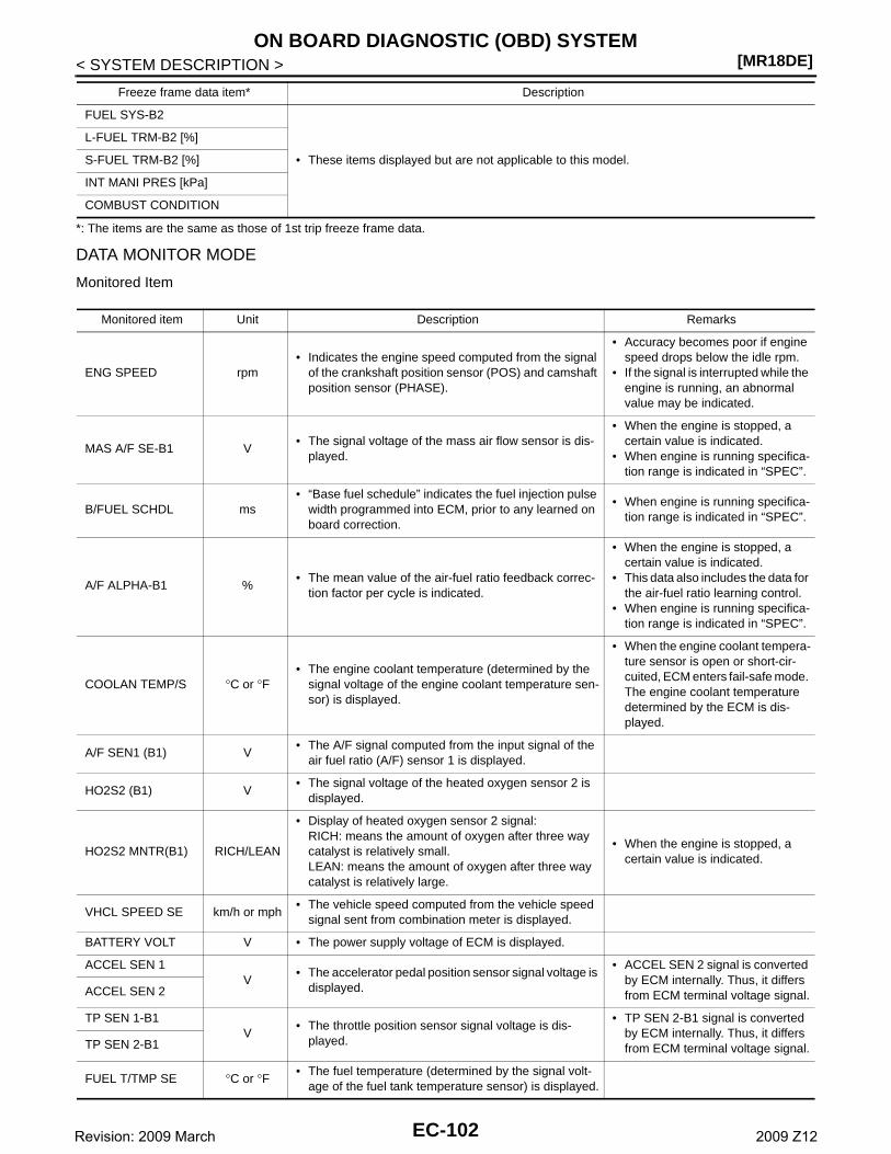
[MR18DE]ON BOARD DIAGNOSTIC (OBD) SYSTEM
< SYSTEM DESCRIPTION >
*: The items are the same as those of 1st trip freeze frame data.
DATA MONITOR MODE
Monitored Item
FUEL SYS-B2
• These items displayed but are not applicable to this model.
L-FUEL TRM-B2 [%]
S-FUEL TRM-B2 [%]
INT MANI PRES [kPa]
COMBUST CONDITION
Freeze frame data item* Description
Monitored item Unit Description Remarks
ENG SPEED rpm• Indicates the engine speed computed from the signal
of the crankshaft position sensor (POS) and camshaft position sensor (PHASE).
• Accuracy becomes poor if engine speed drops below the idle rpm.
• If the signal is interrupted while the engine is running, an abnormal value may be indicated.
MAS A/F SE-B1 V• The signal voltage of the mass air flow sensor is dis-
played.
• When the engine is stopped, a certain value is indicated.
• When engine is running specifica-tion range is indicated in “SPEC”.
B/FUEL SCHDL ms• “Base fuel schedule” indicates the fuel injection pulse
width programmed into ECM, prior to any learned on board correction.
• When engine is running specifica-tion range is indicated in “SPEC”.
A/F ALPHA-B1 %• The mean value of the air-fuel ratio feedback correc-
tion factor per cycle is indicated.
• When the engine is stopped, a certain value is indicated.
• This data also includes the data for the air-fuel ratio learning control.
• When engine is running specifica-tion range is indicated in “SPEC”.
COOLAN TEMP/S °C or °F• The engine coolant temperature (determined by the
signal voltage of the engine coolant temperature sen-sor) is displayed.
• When the engine coolant tempera-ture sensor is open or short-cir-cuited, ECM enters fail-safe mode. The engine coolant temperature determined by the ECM is dis-played.
A/F SEN1 (B1) V• The A/F signal computed from the input signal of the
air fuel ratio (A/F) sensor 1 is displayed.
HO2S2 (B1) V• The signal voltage of the heated oxygen sensor 2 is
displayed.
HO2S2 MNTR(B1) RICH/LEAN
• Display of heated oxygen sensor 2 signal:RICH: means the amount of oxygen after three way catalyst is relatively small.LEAN: means the amount of oxygen after three way catalyst is relatively large.
• When the engine is stopped, a certain value is indicated.
VHCL SPEED SE km/h or mph• The vehicle speed computed from the vehicle speed
signal sent from combination meter is displayed.
BATTERY VOLT V • The power supply voltage of ECM is displayed.
ACCEL SEN 1V
• The accelerator pedal position sensor signal voltage is displayed.
• ACCEL SEN 2 signal is converted by ECM internally. Thus, it differs from ECM terminal voltage signal.ACCEL SEN 2
TP SEN 1-B1V
• The throttle position sensor signal voltage is dis-played.
• TP SEN 2-B1 signal is converted by ECM internally. Thus, it differs from ECM terminal voltage signal.TP SEN 2-B1
FUEL T/TMP SE °C or °F • The fuel temperature (determined by the signal volt-age of the fuel tank temperature sensor) is displayed.
EC-102Revision: 2009 March 2009 Z12
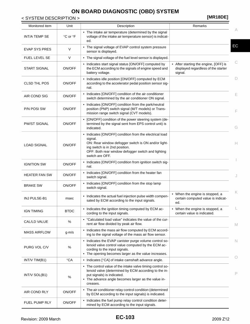
ON BOARD DIAGNOSTIC (OBD) SYSTEM[MR18DE]
C
D
E
F
G
H
I
J
K
L
M
A
C
N
P
O
< SYSTEM DESCRIPTION >
E
INT/A TEMP SE °C or °F• The intake air temperature (determined by the signal
voltage of the intake air temperature sensor) is indicat-ed.
EVAP SYS PRES V• The signal voltage of EVAP control system pressure
sensor is displayed.
FUEL LEVEL SE V • The signal voltage of the fuel level sensor is displayed.
START SIGNAL ON/OFF• Indicates start signal status [ON/OFF] computed by
the ECM according to the signals of engine speed and battery voltage.
• After starting the engine, [OFF] is displayed regardless of the starter signal.
CLSD THL POS ON/OFF• Indicates idle position [ON/OFF] computed by ECM
according to the accelerator pedal position sensor sig-nal.
AIR COND SIG ON/OFF• Indicates [ON/OFF] condition of the air conditioner
switch determined by the air conditioner ON signal.
P/N POSI SW ON/OFF• Indicates [ON/OFF] condition from the park/neutral
position (PNP) switch signal (M/T models) or Trans-mission range switch signal (CVT models).
PW/ST SIGNAL ON/OFF• [ON/OFF] condition of the power steering system (de-
termined by the signal sent from EPS control unit) is indicated.
LOAD SIGNAL ON/OFF
• Indicates [ON/OFF] condition from the electrical load signal.ON: Rear window defogger switch is ON and/or light-ing switch is in 2nd position.OFF: Both rear window defogger switch and lighting switch are OFF.
IGNITION SW ON/OFF• Indicates [ON/OFF] condition from ignition switch sig-
nal.
HEATER FAN SW ON/OFF• Indicates [ON/OFF] condition from the heater fan
switch signal.
BRAKE SW ON/OFF• Indicates [ON/OFF] condition from the stop lamp
switch signal.
INJ PULSE-B1 msec• Indicates the actual fuel injection pulse width compen-
sated by ECM according to the input signals.
• When the engine is stopped, a certain computed value is indicat-ed.
IGN TIMING BTDC• Indicates the ignition timing computed by ECM ac-
cording to the input signals.• When the engine is stopped, a
certain value is indicated.
CAL/LD VALUE %• “Calculated load value” indicates the value of the cur-
rent air flow divided by peak air flow.
MASS AIRFLOW g·m/s• Indicates the mass air flow computed by ECM accord-
ing to the signal voltage of the mass air flow sensor.
PURG VOL C/V %
• Indicates the EVAP canister purge volume control so-lenoid valve control value computed by the ECM ac-cording to the input signals.
• The opening becomes larger as the value increases.
INT/V TIM(B1) °CA • Indicates [°CA] of intake camshaft advance angle.
INT/V SOL(B1)%
• The control value of the intake valve timing control so-lenoid valve (determined by ECM according to the in-put signals) is indicated.
• The advance angle becomes larger as the value in-creases.
AIR COND RLY ON/OFF• The air conditioner relay control condition (determined
by ECM according to the input signals) is indicated.
FUEL PUMP RLY ON/OFF• Indicates the fuel pump relay control condition deter-
mined by ECM according to the input signals.
Monitored item Unit Description Remarks
EC-103Revision: 2009 March 2009 Z12
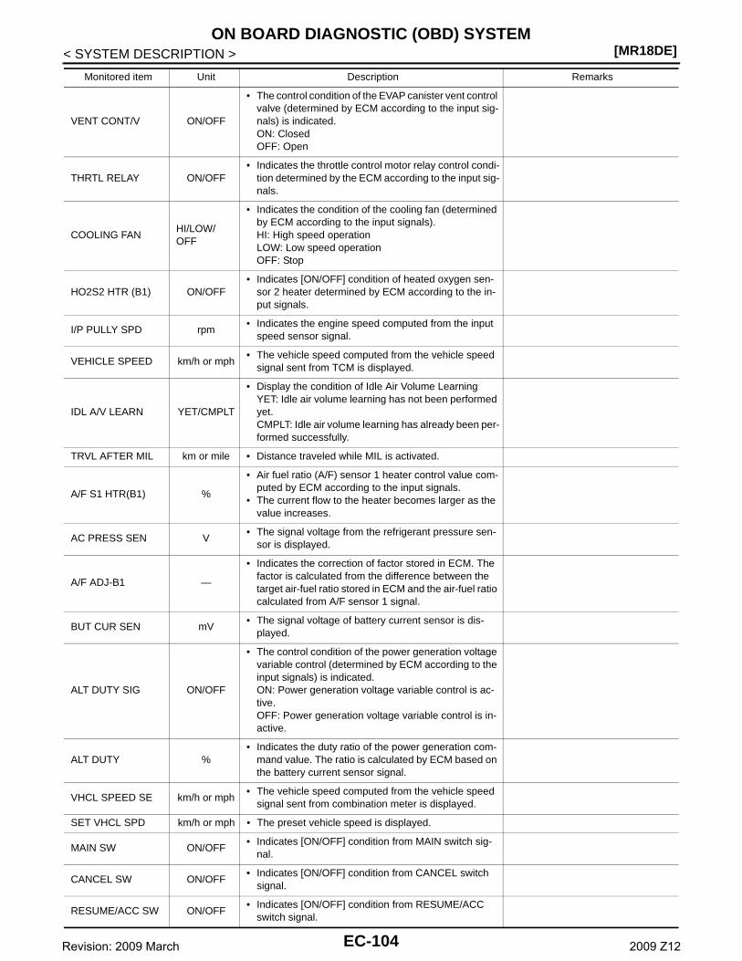
[MR18DE]ON BOARD DIAGNOSTIC (OBD) SYSTEM
< SYSTEM DESCRIPTION >
VENT CONT/V ON/OFF
• The control condition of the EVAP canister vent control valve (determined by ECM according to the input sig-nals) is indicated.ON: ClosedOFF: Open
THRTL RELAY ON/OFF• Indicates the throttle control motor relay control condi-
tion determined by the ECM according to the input sig-nals.
COOLING FANHI/LOW/OFF
• Indicates the condition of the cooling fan (determined by ECM according to the input signals).HI: High speed operationLOW: Low speed operationOFF: Stop
HO2S2 HTR (B1) ON/OFF• Indicates [ON/OFF] condition of heated oxygen sen-
sor 2 heater determined by ECM according to the in-put signals.
I/P PULLY SPD rpm• Indicates the engine speed computed from the input
speed sensor signal.
VEHICLE SPEED km/h or mph• The vehicle speed computed from the vehicle speed
signal sent from TCM is displayed.
IDL A/V LEARN YET/CMPLT
• Display the condition of Idle Air Volume LearningYET: Idle air volume learning has not been performed yet.CMPLT: Idle air volume learning has already been per-formed successfully.
TRVL AFTER MIL km or mile • Distance traveled while MIL is activated.
A/F S1 HTR(B1) %
• Air fuel ratio (A/F) sensor 1 heater control value com-puted by ECM according to the input signals.
• The current flow to the heater becomes larger as the value increases.
AC PRESS SEN V• The signal voltage from the refrigerant pressure sen-
sor is displayed.
A/F ADJ-B1 —
• Indicates the correction of factor stored in ECM. The factor is calculated from the difference between the target air-fuel ratio stored in ECM and the air-fuel ratio calculated from A/F sensor 1 signal.
BUT CUR SEN mV• The signal voltage of battery current sensor is dis-
played.
ALT DUTY SIG ON/OFF
• The control condition of the power generation voltage variable control (determined by ECM according to the input signals) is indicated.ON: Power generation voltage variable control is ac-tive.OFF: Power generation voltage variable control is in-active.
ALT DUTY %• Indicates the duty ratio of the power generation com-
mand value. The ratio is calculated by ECM based on the battery current sensor signal.
VHCL SPEED SE km/h or mph• The vehicle speed computed from the vehicle speed
signal sent from combination meter is displayed.
SET VHCL SPD km/h or mph • The preset vehicle speed is displayed.
MAIN SW ON/OFF• Indicates [ON/OFF] condition from MAIN switch sig-
nal.
CANCEL SW ON/OFF• Indicates [ON/OFF] condition from CANCEL switch
signal.
RESUME/ACC SW ON/OFF• Indicates [ON/OFF] condition from RESUME/ACC
switch signal.
Monitored item Unit Description Remarks
EC-104Revision: 2009 March 2009 Z12
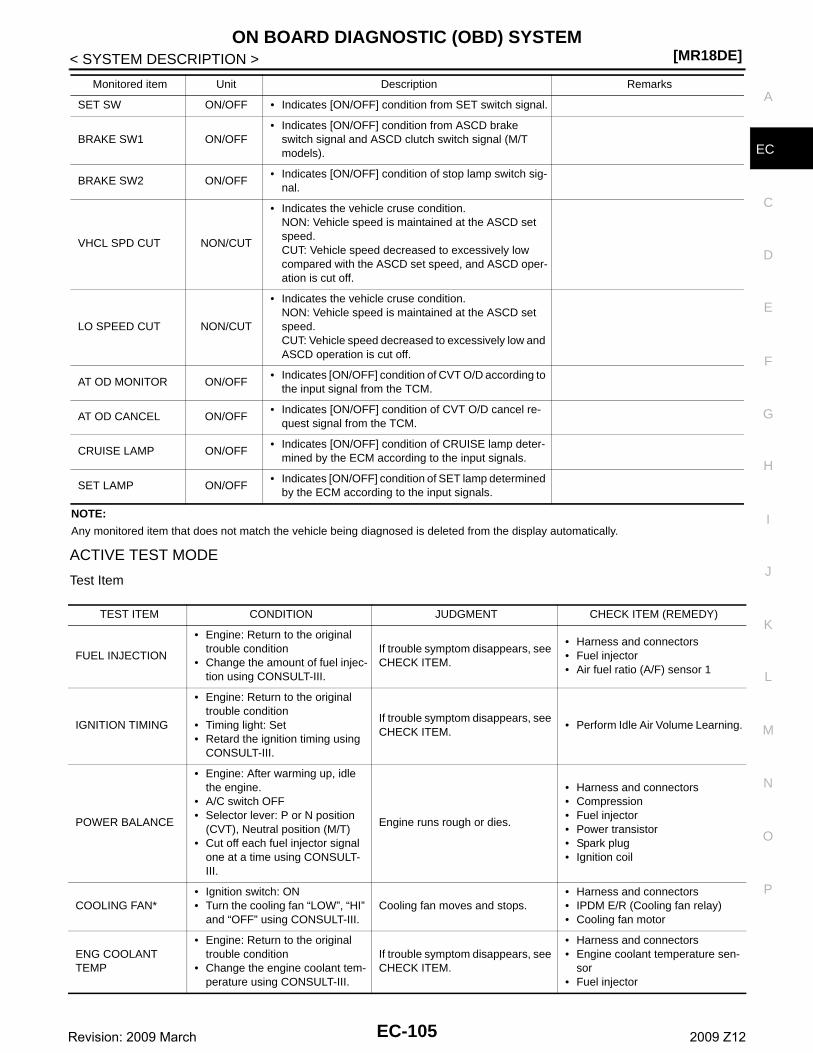
ON BOARD DIAGNOSTIC (OBD) SYSTEM[MR18DE]
C
D
E
F
G
H
I
J
K
L
M
A
C
N
P
O
< SYSTEM DESCRIPTION >
E
NOTE:
Any monitored item that does not match the vehicle being diagnosed is deleted from the display automatically.
ACTIVE TEST MODE
Test Item
SET SW ON/OFF • Indicates [ON/OFF] condition from SET switch signal.
BRAKE SW1 ON/OFF• Indicates [ON/OFF] condition from ASCD brake
switch signal and ASCD clutch switch signal (M/T models).
BRAKE SW2 ON/OFF• Indicates [ON/OFF] condition of stop lamp switch sig-
nal.
VHCL SPD CUT NON/CUT
• Indicates the vehicle cruse condition.NON: Vehicle speed is maintained at the ASCD set speed.CUT: Vehicle speed decreased to excessively low compared with the ASCD set speed, and ASCD oper-ation is cut off.
LO SPEED CUT NON/CUT
• Indicates the vehicle cruse condition.NON: Vehicle speed is maintained at the ASCD set speed.CUT: Vehicle speed decreased to excessively low and ASCD operation is cut off.
AT OD MONITOR ON/OFF• Indicates [ON/OFF] condition of CVT O/D according to
the input signal from the TCM.
AT OD CANCEL ON/OFF• Indicates [ON/OFF] condition of CVT O/D cancel re-
quest signal from the TCM.
CRUISE LAMP ON/OFF• Indicates [ON/OFF] condition of CRUISE lamp deter-
mined by the ECM according to the input signals.
SET LAMP ON/OFF• Indicates [ON/OFF] condition of SET lamp determined
by the ECM according to the input signals.
Monitored item Unit Description Remarks
TEST ITEM CONDITION JUDGMENT CHECK ITEM (REMEDY)
FUEL INJECTION
• Engine: Return to the original trouble condition
• Change the amount of fuel injec-tion using CONSULT-III.
If trouble symptom disappears, see CHECK ITEM.
• Harness and connectors• Fuel injector• Air fuel ratio (A/F) sensor 1
IGNITION TIMING
• Engine: Return to the original trouble condition
• Timing light: Set• Retard the ignition timing using
CONSULT-III.
If trouble symptom disappears, see CHECK ITEM.
• Perform Idle Air Volume Learning.
POWER BALANCE
• Engine: After warming up, idle the engine.
• A/C switch OFF• Selector lever: P or N position
(CVT), Neutral position (M/T)• Cut off each fuel injector signal
one at a time using CONSULT-III.
Engine runs rough or dies.
• Harness and connectors• Compression• Fuel injector• Power transistor• Spark plug• Ignition coil
COOLING FAN*• Ignition switch: ON• Turn the cooling fan “LOW”, “HI”
and “OFF” using CONSULT-III.Cooling fan moves and stops.
• Harness and connectors• IPDM E/R (Cooling fan relay)• Cooling fan motor
ENG COOLANT TEMP
• Engine: Return to the original trouble condition
• Change the engine coolant tem-perature using CONSULT-III.
If trouble symptom disappears, see CHECK ITEM.
• Harness and connectors• Engine coolant temperature sen-
sor• Fuel injector
EC-105Revision: 2009 March 2009 Z12
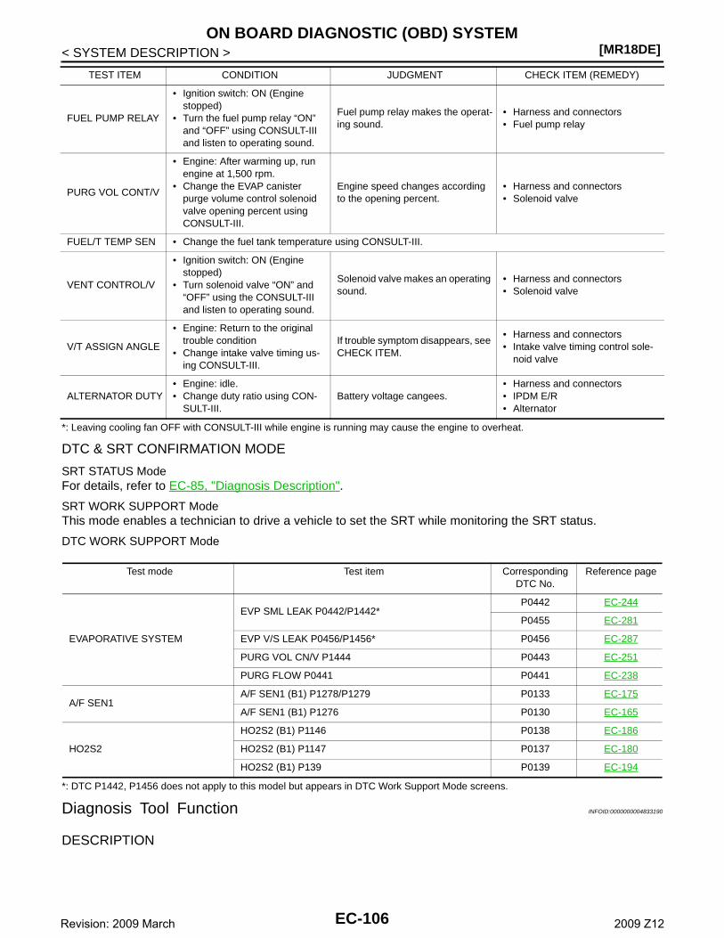
[MR18DE]ON BOARD DIAGNOSTIC (OBD) SYSTEM
< SYSTEM DESCRIPTION >
*: Leaving cooling fan OFF with CONSULT-III while engine is running may cause the engine to overheat.
DTC & SRT CONFIRMATION MODE
SRT STATUS ModeFor details, refer to EC-85, "Diagnosis Description".
SRT WORK SUPPORT ModeThis mode enables a technician to drive a vehicle to set the SRT while monitoring the SRT status.
DTC WORK SUPPORT Mode
*: DTC P1442, P1456 does not apply to this model but appears in DTC Work Support Mode screens.
Diagnosis Tool Function INFOID:0000000004833190
DESCRIPTION
FUEL PUMP RELAY
• Ignition switch: ON (Engine stopped)
• Turn the fuel pump relay “ON” and “OFF” using CONSULT-III and listen to operating sound.
Fuel pump relay makes the operat-ing sound.
• Harness and connectors• Fuel pump relay
PURG VOL CONT/V
• Engine: After warming up, run engine at 1,500 rpm.
• Change the EVAP canister purge volume control solenoid valve opening percent using CONSULT-III.
Engine speed changes according to the opening percent.
• Harness and connectors• Solenoid valve
FUEL/T TEMP SEN • Change the fuel tank temperature using CONSULT-III.
VENT CONTROL/V
• Ignition switch: ON (Engine stopped)
• Turn solenoid valve “ON” and “OFF” using the CONSULT-III and listen to operating sound.
Solenoid valve makes an operating sound.
• Harness and connectors• Solenoid valve
V/T ASSIGN ANGLE
• Engine: Return to the original trouble condition
• Change intake valve timing us-ing CONSULT-III.
If trouble symptom disappears, see CHECK ITEM.
• Harness and connectors• Intake valve timing control sole-
noid valve
ALTERNATOR DUTY• Engine: idle.• Change duty ratio using CON-
SULT-III.Battery voltage cangees.
• Harness and connectors• IPDM E/R• Alternator
TEST ITEM CONDITION JUDGMENT CHECK ITEM (REMEDY)
Test mode Test item Corresponding DTC No.
Reference page
EVAPORATIVE SYSTEM
EVP SML LEAK P0442/P1442*P0442 EC-244
P0455 EC-281
EVP V/S LEAK P0456/P1456* P0456 EC-287
PURG VOL CN/V P1444 P0443 EC-251
PURG FLOW P0441 P0441 EC-238
A/F SEN1A/F SEN1 (B1) P1278/P1279 P0133 EC-175
A/F SEN1 (B1) P1276 P0130 EC-165
HO2S2
HO2S2 (B1) P1146 P0138 EC-186
HO2S2 (B1) P1147 P0137 EC-180
HO2S2 (B1) P139 P0139 EC-194
EC-106Revision: 2009 March 2009 Z12
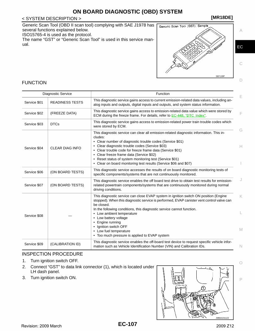
ON BOARD DIAGNOSTIC (OBD) SYSTEM[MR18DE]
C
D
E
F
G
H
I
J
K
L
M
A
C
N
P
O
< SYSTEM DESCRIPTION >
E
Generic Scan Tool (OBD II scan tool) complying with SAE J1978 hasseveral functions explained below.ISO15765-4 is used as the protocol.The name “GST” or “Generic Scan Tool” is used in this service man-ual.
FUNCTION
INSPECTION PROCEDURE1. Turn ignition switch OFF.2. Connect “GST” to data link connector (1), which is located under
LH dash panel.3. Turn ignition switch ON.
SEF139P
Diagnostic Service Function
Service $01 READINESS TESTSThis diagnostic service gains access to current emission-related data values, including an-alog inputs and outputs, digital inputs and outputs, and system status information.
Service $02 (FREEZE DATA)This diagnostic service gains access to emission-related data value which were stored by ECM during the freeze frame. For details, refer to EC-448, "DTC Index".
Service $03 DTCsThis diagnostic service gains access to emission-related power train trouble codes which were stored by ECM.
Service $04 CLEAR DIAG INFO
This diagnostic service can clear all emission-related diagnostic information. This in-cludes:• Clear number of diagnostic trouble codes (Service $01)• Clear diagnostic trouble codes (Service $03)• Clear trouble code for freeze frame data (Service $01)• Clear freeze frame data (Service $02)• Reset status of system monitoring test (Service $01)• Clear on board monitoring test results (Service $06 and $07)
Service $06 (ON BOARD TESTS)This diagnostic service accesses the results of on board diagnostic monitoring tests of specific components/systems that are not continuously monitored.
Service $07 (ON BOARD TESTS)This diagnostic service enables the off board test drive to obtain test results for emission-related powertrain components/systems that are continuously monitored during normal driving conditions.
Service $08 —
This diagnostic service can close EVAP system in ignition switch ON position (Engine stopped). When this diagnostic service is performed, EVAP canister vent control valve can be closed.In the following conditions, this diagnostic service cannot function.• Low ambient temperature• Low battery voltage• Engine running• Ignition switch OFF• Low fuel temperature• Too much pressure is applied to EVAP system
Service $09 (CALIBRATION ID)This diagnostic service enables the off-board test device to request specific vehicle infor-mation such as Vehicle Identification Number (VIN) and Calibration IDs.
JMBIA2311ZZ
EC-107Revision: 2009 March 2009 Z12
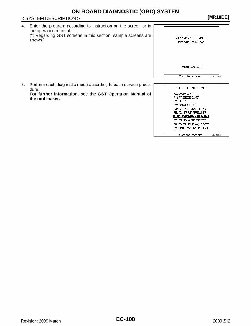
[MR18DE]ON BOARD DIAGNOSTIC (OBD) SYSTEM
< SYSTEM DESCRIPTION >
4. Enter the program according to instruction on the screen or inthe operation manual.(*: Regarding GST screens in this section, sample screens areshown.)
5. Perform each diagnostic mode according to each service proce-dure.For further information, see the GST Operation Manual ofthe tool maker.
SEF398S
SEF416S
EC-108Revision: 2009 March 2009 Z12
TROUBLE DIAGNOSIS - SPECIFICATION VALUE[MR18DE]
C
D
E
F
G
H
I
J
K
L
M
A
C
N
P
O
< DTC/CIRCUIT DIAGNOSIS >
E
DTC/CIRCUIT DIAGNOSISTROUBLE DIAGNOSIS - SPECIFICATION VALUE
Description INFOID:0000000004833191
The specification (SP) value indicates the tolerance of the value that is displayed in “SPEC” of “DATA MONI-TOR” mode of CONSULT-III during normal operation of the Engine Control System. When the value in “SPEC”of “DATA MONITOR” mode is within the SP value, the Engine Control System is confirmed OK. When thevalue in “SPEC” of “DATA MONITOR” mode is NOT within the SP value, the Engine Control System may haveone or more malfunctions.The SP value is used to detect malfunctions that may affect the Engine Control System, but will not light theMIL.The SP value will be displayed for the following three items:• B/FUEL SCHDL (The fuel injection pulse width programmed into ECM prior to any learned on board correc-
tion)• A/F ALPHA-B1 (The mean value of air-fuel ratio feedback correction factor per cycle)• MAS A/F SE-B1 (The signal voltage of the mass air flow sensor)
Component Function Check INFOID:0000000004833192
1.START
Make sure that all of the following conditions are satisfied.• Vehicle driven distance: More than 5,000 km (3,107 miles)• Barometric pressure: 98.3 - 104.3 kPa (1.003 - 1.064 kg/cm2, 14.25 - 15.12 psi)• Atmospheric temperature: 20 - 30°C (68 - 86°F)• Engine coolant temperature: 75 - 95°C (167 - 203°F)• Transmission: Warmed-up- CVT models: After the engine is warmed up to normal operating temperature, drive vehicle until “FLUID
TEMP SE” (CVT fluid temperature sensor signal) indicates more than 60°C (140°F).- M/T models: After the engine is warmed up to normal operating temperature, drive vehicle for 5 minutes.• Electrical load: Not applied- Rear window defogger switch, air conditioner switch, lighting switch are OFF. Steering wheel is straight
ahead.• Engine speed: Idle
>> GO TO 2.
2.PERFORM “SPEC” OF “DATA MONITOR” MODE
With CONSULT-IIINOTE:Perform “SPEC” in “DATA MONITOR” mode in maximum scale display.1. Perform EC-12, "BASIC INSPECTION : Special Repair Requirement".2. Select “B/FUEL SCHDL”, “A/F ALPHA-B1” and “MAS A/F SE-B1” in “SPEC” of “DATA MONITOR” mode
with CONSULT-III.3. Make sure that monitor items are within the SP value.Is the inspection result normal?YES >> ENDNO >> Go to EC-110, "Diagnosis Procedure".
EC-109Revision: 2009 March 2009 Z12
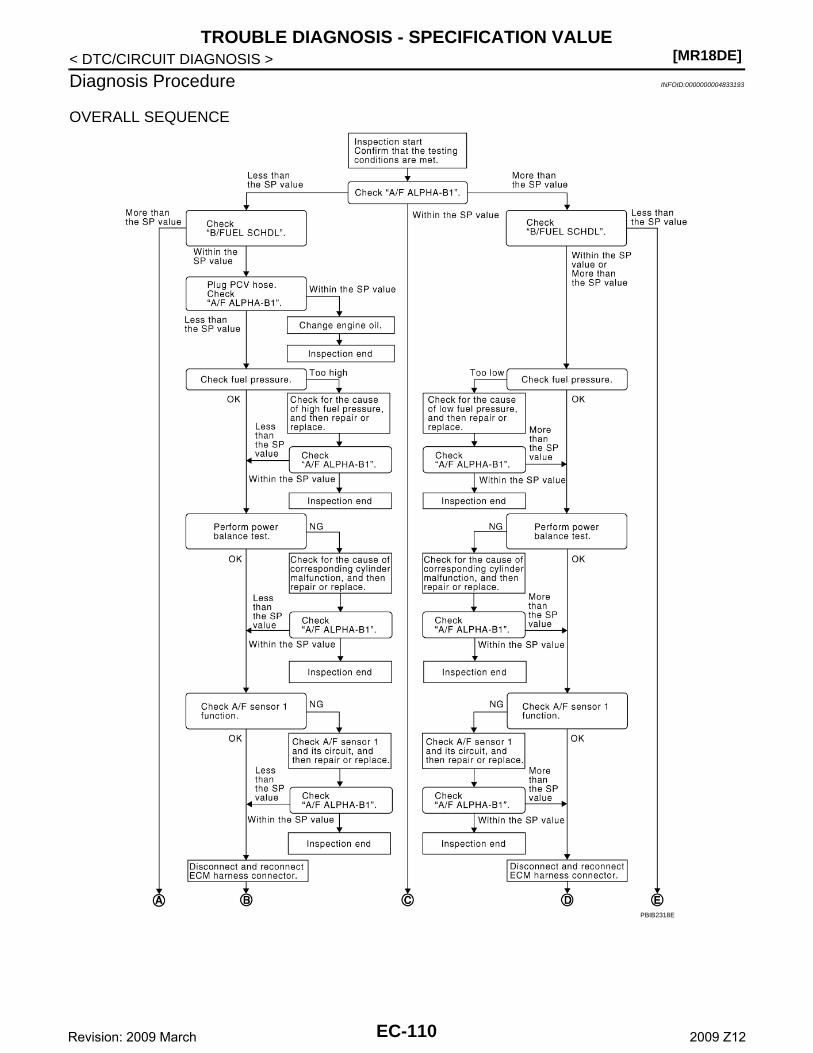
[MR18DE]TROUBLE DIAGNOSIS - SPECIFICATION VALUE
< DTC/CIRCUIT DIAGNOSIS >
Diagnosis Procedure INFOID:0000000004833193
OVERALL SEQUENCE
PBIB2318E
EC-110Revision: 2009 March 2009 Z12
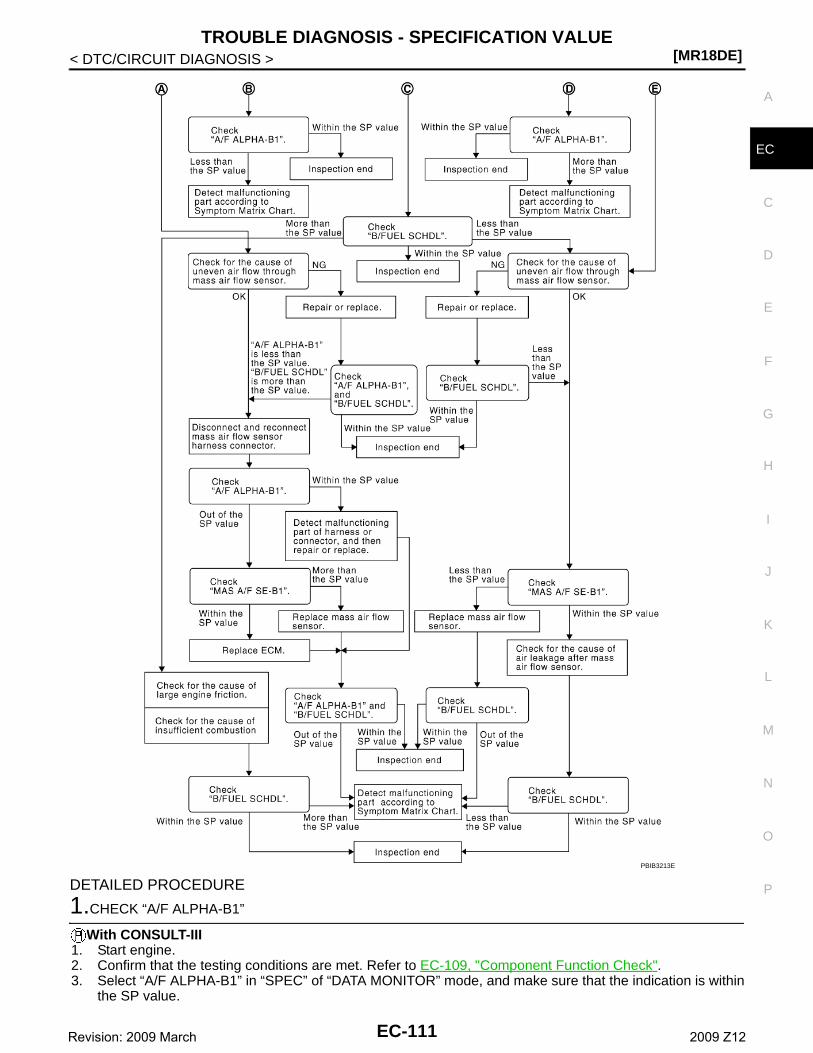
TROUBLE DIAGNOSIS - SPECIFICATION VALUE[MR18DE]
C
D
E
F
G
H
I
J
K
L
M
A
C
N
P
O
< DTC/CIRCUIT DIAGNOSIS >
E
DETAILED PROCEDURE
1.CHECK “A/F ALPHA-B1”
With CONSULT-III1. Start engine.2. Confirm that the testing conditions are met. Refer to EC-109, "Component Function Check".3. Select “A/F ALPHA-B1” in “SPEC” of “DATA MONITOR” mode, and make sure that the indication is within
the SP value.
PBIB3213E
EC-111Revision: 2009 March 2009 Z12
[MR18DE]TROUBLE DIAGNOSIS - SPECIFICATION VALUE
< DTC/CIRCUIT DIAGNOSIS >NOTE:Check “A/F ALPHA-B1” for approximately 1 minute because it may fluctuate. It is NG if the indication isout of the SP value even a little.
Is the measurement value within the SP value?YES >> GO TO 17.NO-1 >> Less than the SP value: GO TO 2.NO-2 >> More than the SP value: GO TO 3.
2.CHECK “B/FUEL SCHDL”
Select “B/FUEL SCHDL” in “SPEC” of “DATA MONITOR” mode, and make sure that the indication is within theSP value.Is the measurement value within the SP value?YES >> GO TO 4.NO >> More than the SP value: GO TO 19.
3.CHECK “B/FUEL SCHDL”
Select “B/FUEL SCHDL” in “SPEC” of “DATA MONITOR” mode, and make sure that the indication is within theSP value.Is the measurement value within the SP value?YES >> GO TO 6.NO-1 >> More than the SP value: GO TO 6.NO-2 >> Less than the SP value: GO TO 25.
4.CHECK “A/F ALPHA-B1”
1. Stop the engine.2. Disconnect PCV hose, and then plug it.3. Start engine.4. Select “A/F ALPHA-B1” in “SPEC” of “DATA MONITOR” mode, and make sure that the indication is within
the SP value.Is the measurement value within the SP value?YES >> GO TO 5.NO >> GO TO 6.
5.CHANGE ENGINE OIL
1. Stop the engine.2. Change engine oil.
NOTE:This symptom may occur when a large amount of gasoline is mixed with engine oil because of drivingconditions (such as when engine oil temperature does not rise enough since a journey distance is tooshort during winter). The symptom will not be detected after changing engine oil or changing driving con-dition.
>> INSPECTION END
6.CHECK FUEL PRESSURE
Check fuel pressure. (Refer to EC-471, "Inspection".)Is the inspection result normal?YES >> GO TO 9.NO-1 >> Fuel pressure is too high: Replace “fuel filter and fuel pump assembly” and then GO TO 8.NO-2 >> Fuel pressure is too low: GO TO 7.
7.DETECT MALFUNCTIONING PART
Check fuel hoses and fuel tubes for cloggingIs the inspection result normal?YES >> Replace “fuel filter and fuel pump assembly” and then GO TO 8.NO >> Repair or replace and then GO TO 8.
8.CHECK “A/F ALPHA-B1”
EC-112Revision: 2009 March 2009 Z12
TROUBLE DIAGNOSIS - SPECIFICATION VALUE[MR18DE]
C
D
E
F
G
H
I
J
K
L
M
A
C
N
P
O
< DTC/CIRCUIT DIAGNOSIS >
E
1. Start engine.2. Select “A/F ALPHA-B1” in “SPEC” of “DATA MONITOR” mode, and make sure that the indication is within
the SP value.Is the measurement value within the SP value?YES >> INSPECTION ENDNO >> GO TO 9.
9.PERFORM POWER BALANCE TEST
1. Perform “POWER BALANCE” in “ACTIVE TEST” mode.2. Make sure that the each cylinder produces a momentary engine speed drop.Is the inspection result normal?YES >> GO TO 12.NO >> GO TO 10.
10.DETECT MALFUNCTIONING PART
Check the following.1. Ignition coil and its circuit (Refer to EC-401, "Component Function Check".)2. Fuel injector and its circuit (Refer to EC-395, "Component Function Check".)3. Intake air leakage4. Low compression pressure (Refer to EM-21, "Inspection".)Is the inspection result normal?YES >> Replace fuel injector and then GO TO 11.NO >> Repair or replace malfunctioning part and then GO TO 11.
11.CHECK “A/F ALPHA-B1”
1. Start engine.2. Select “A/F ALPHA-B1” in “SPEC” of “DATA MONITOR” mode, and make sure that the indication is within
the SP value.Is the measurement value within the SP value?YES >> INSPECTION ENDNO >> GO TO 12.
12.CHECK A/F SENSOR 1 FUNCTION
Perform all DTC CONFIRMATION PROCEDURE related with A/F sensor 1.• For DTC P0130, refer to EC-165, "DTC Logic".• For DTC P0131, refer to EC-169, "DTC Logic".• For DTC P0132, refer to EC-172, "DTC Logic".• For DTC P0133, refer to EC-175, "DTC Logic".• For DTC P2A00, refer to EC-382, "DTC Logic".Is any DTC detected?YES >> GO TO 15.NO >> GO TO 13.
13.CHECK A/F SENSOR 1 CIRCUIT
Perform DIAGNOSTIC PROCEDURE according to corresponding DTC.
>> GO TO 14.
14.CHECK “A/F ALPHA-B1”
1. Start engine.2. Select “A/F ALPHA-B1” in “SPEC” of “DATA MONITOR” mode, and make sure that the indication is within
the SP value.Is the measurement value within the SP value?YES >> INSPECTION ENDNO >> GO TO 15.
15.DISCONNECT AND RECONNECT ECM HARNESS CONNECTOR
1. Stop the engine.
EC-113Revision: 2009 March 2009 Z12
[MR18DE]TROUBLE DIAGNOSIS - SPECIFICATION VALUE
< DTC/CIRCUIT DIAGNOSIS >2. Disconnect ECM harness connector.3. Check pin terminal and connector for damage, and then reconnect it.
>> GO TO 16.
16.CHECK “A/F ALPHA-B1”
1. Start engine.2. Select “A/F ALPHA-B1” in “SPEC” of “DATA MONITOR” mode, and make sure that the indication is within
the SP value.Is the measurement value within the SP value?YES >> INSPECTION ENDNO >> Detect malfunctioning part according to EC-460, "Symptom Table".
17.CHECK “B/FUEL SCHDL”
Select “B/FUEL SCHDL” in “SPEC” of “DATA MONITOR” mode, and make sure that the indication is within theSP value.Is the measurement value within the SP value?YES >> INSPECTION ENDNO-1 >> More than the SP value: GO TO 18.NO-2 >> Less than the SP value: GO TO 25.
18.DETECT MALFUNCTIONING PART
1. Check for the cause of large engine friction. Refer to the following.- Engine oil level is too high- Engine oil viscosity- Belt tension of power steering, alternator, A/C compressor, etc. is excessive- Noise from engine- Noise from transmission, etc.2. Check for the cause of insufficient combustion. Refer to the following.- Valve clearance malfunction- Intake valve timing control function malfunction- Camshaft sprocket installation malfunction, etc.
>> Repair or replace malfunctioning part, and then GO TO 30.
19.CHECK INTAKE SYSTEM
Check for the cause of uneven air flow through mass air flow sensor. Refer to the following.• Crushed air ducts• Malfunctioning seal of air cleaner element• Uneven dirt of air cleaner element• Improper specification of intake air systemIs the inspection result normal?YES >> GO TO 21.NO >> Repair or replace malfunctioning part, and then GO TO 20.
20.CHECK “A/F ALPHA-B1”, AND “B/FUEL SCHDL”
Select “A/F ALPHA-B1” and “B/FUEL SCHDL” in “SPEC” of “DATA MONITOR” mode, and make sure thateach indication is within the SP value.Is the measurement value within the SP value?YES >> INSPECTION ENDNO >> “B/FUEL SCHDL” is more, “A/F ALPHA-B1” is less than the SP value: GO TO 21.
21.DISCONNECT AND RECONNECT MASS AIR FLOW SENSOR HARNESS CONNECTOR
1. Stop the engine.2. Disconnect mass air flow sensor harness connector.3. Check pin terminal and connector for damage and then reconnect it again.
>> GO TO 22.
EC-114Revision: 2009 March 2009 Z12
TROUBLE DIAGNOSIS - SPECIFICATION VALUE[MR18DE]
C
D
E
F
G
H
I
J
K
L
M
A
C
N
P
O
< DTC/CIRCUIT DIAGNOSIS >
E
22.CHECK “A/F ALPHA-B1”
1. Start engine.2. Select “A/F ALPHA-B1” in “SPEC” of “DATA MONITOR” mode, and make sure that the indication is within
the SP value.Is the measurement value within the SP value?YES >> Detect malfunctioning part of mass air flow sensor circuit and repair it. Refer to EC-136, "DTC
Logic". Then GO TO 29.NO >> GO TO 23.
23.CHECK “MAS A/F SE-B1”
Select “MAS A/F SE-B1” in “SPEC” of “DATA MONITOR” mode, and make sure that the indication is within theSP value.Is the measurement value within the SP value?YES >> GO TO 24.NO >> More than the SP value: Replace mass air flow sensor, and then GO TO 29.
24.REPLACE ECM
1. Replace ECM.2. Perform EC-15, "ADDITIONAL SERVICE WHEN REPLACING CONTROL UNIT : Special Repair Require-
ment".
>> GO TO 29.
25.CHECK INTAKE SYSTEM
Check for the cause of uneven air flow through mass air flow sensor. Refer to the following.• Crushed air ducts• Malfunctioning seal of air cleaner element• Uneven dirt of air cleaner element• Improper specification of intake air systemIs the inspection result normal?YES >> GO TO 27.NO >> Repair or replace malfunctioning part, and then GO TO 26.
26.CHECK “B/FUEL SCHDL”
Select “B/FUEL SCHDL” in “SPEC” of “DATA MONITOR” mode, and make sure that the indication is within theSP value.Is the measurement value within the SP value?YES >> INSPECTION ENDNO >> Less than the SP value: GO TO 27.
27.CHECK “MAS A/F SE-B1”
Select “MAS A/F SE-B1” in “SPEC” of “DATA MONITOR” mode, and make sure that the indication is within theSP value.Is the measurement value within the SP value?YES >> GO TO 28.NO >> Less than the SP value: Replace mass air flow sensor, and then GO TO 30.
28.CHECK INTAKE SYSTEM
Check for the cause of air leak after the mass air flow sensor. Refer to the following.• Disconnection, looseness, and cracks in air duct• Looseness of oil filler cap• Disconnection of oil level gauge• Open stuck, breakage, hose disconnection, or cracks of PCV valve• Disconnection or cracks of EVAP purge hose, open stuck of EVAP canister purge volume control solenoid
valve• Malfunctioning seal of rocker cover gasket• Disconnection, looseness, or cracks of hoses, such as vacuum hose, connecting to intake air system parts
EC-115Revision: 2009 March 2009 Z12
[MR18DE]TROUBLE DIAGNOSIS - SPECIFICATION VALUE
< DTC/CIRCUIT DIAGNOSIS >• Malfunctioning seal of intake air system, etc.
>> GO TO 30.
29.CHECK “A/F ALPHA-B1” AND “B/FUEL SCHDL”
Select “A/F ALPHA-B1” and “B/FUEL SCHDL” in “SPEC” of “DATA MONITOR” mode, and make sure thateach indication is within the SP value. Is the measurement value within the SP value?YES >> INSPECTION ENDNO >> Detect malfunctioning part according to EC-460, "Symptom Table".
30.CHECK “B/FUEL SCHDL”
Select “B/FUEL SCHDL” in “SPEC” of “DATA MONITOR” mode, and then make sure that the indication iswithin the SP value.Is the measurement value within the SP value?YES >> INSPECTION ENDNO >> Detect malfunctioning part according to EC-460, "Symptom Table".
EC-116Revision: 2009 March 2009 Z12
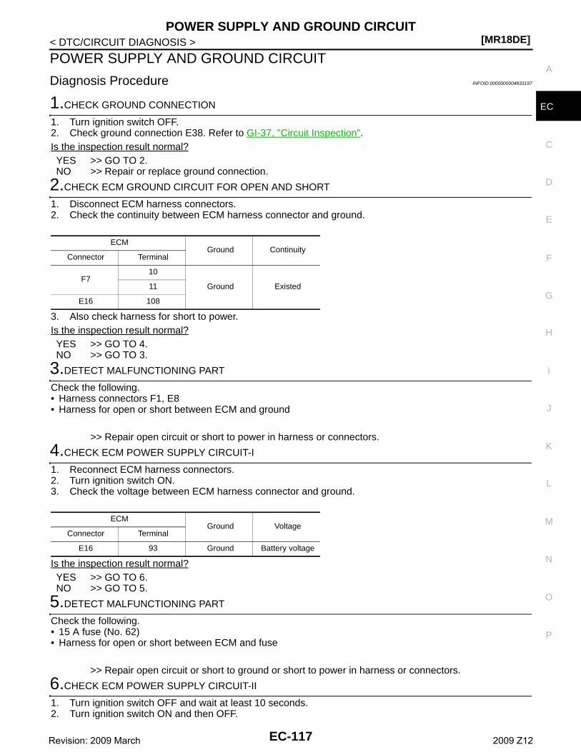
POWER SUPPLY AND GROUND CIRCUIT[MR18DE]
C
D
E
F
G
H
I
J
K
L
M
A
C
N
P
O
< DTC/CIRCUIT DIAGNOSIS >
E
POWER SUPPLY AND GROUND CIRCUIT
Diagnosis Procedure INFOID:0000000004833197
1.CHECK GROUND CONNECTION
1. Turn ignition switch OFF.2. Check ground connection E38. Refer to GI-37, "Circuit Inspection".Is the inspection result normal?YES >> GO TO 2.NO >> Repair or replace ground connection.
2.CHECK ECM GROUND CIRCUIT FOR OPEN AND SHORT
1. Disconnect ECM harness connectors.2. Check the continuity between ECM harness connector and ground.
3. Also check harness for short to power.Is the inspection result normal?YES >> GO TO 4.NO >> GO TO 3.
3.DETECT MALFUNCTIONING PART
Check the following.• Harness connectors F1, E8• Harness for open or short between ECM and ground
>> Repair open circuit or short to power in harness or connectors.
4.CHECK ECM POWER SUPPLY CIRCUIT-I
1. Reconnect ECM harness connectors.2. Turn ignition switch ON.3. Check the voltage between ECM harness connector and ground.
Is the inspection result normal?YES >> GO TO 6.NO >> GO TO 5.
5.DETECT MALFUNCTIONING PART
Check the following.• 15 A fuse (No. 62)• Harness for open or short between ECM and fuse
>> Repair open circuit or short to ground or short to power in harness or connectors.
6.CHECK ECM POWER SUPPLY CIRCUIT-II
1. Turn ignition switch OFF and wait at least 10 seconds.2. Turn ignition switch ON and then OFF.
ECMGround Continuity
Connector Terminal
F710
Ground Existed11
E16 108
ECMGround Voltage
Connector Terminal
E16 93 Ground Battery voltage
EC-117Revision: 2009 March 2009 Z12
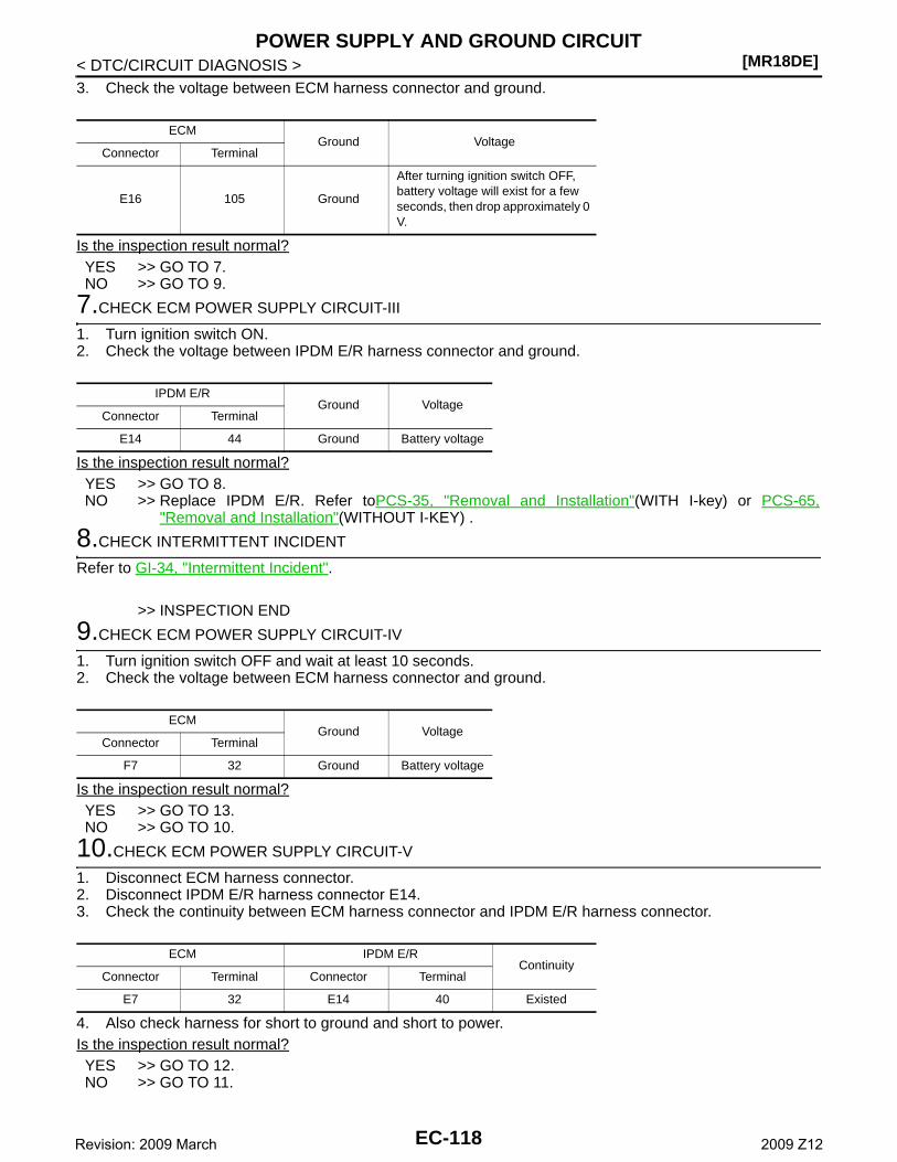
[MR18DE]POWER SUPPLY AND GROUND CIRCUIT
< DTC/CIRCUIT DIAGNOSIS >3. Check the voltage between ECM harness connector and ground.
Is the inspection result normal?YES >> GO TO 7.NO >> GO TO 9.
7.CHECK ECM POWER SUPPLY CIRCUIT-III
1. Turn ignition switch ON.2. Check the voltage between IPDM E/R harness connector and ground.
Is the inspection result normal?YES >> GO TO 8.NO >> Replace IPDM E/R. Refer toPCS-35, "Removal and Installation"(WITH I-key) or PCS-65,
"Removal and Installation"(WITHOUT I-KEY) .
8.CHECK INTERMITTENT INCIDENT
Refer to GI-34, "Intermittent Incident".
>> INSPECTION END
9.CHECK ECM POWER SUPPLY CIRCUIT-IV
1. Turn ignition switch OFF and wait at least 10 seconds.2. Check the voltage between ECM harness connector and ground.
Is the inspection result normal?YES >> GO TO 13.NO >> GO TO 10.
10.CHECK ECM POWER SUPPLY CIRCUIT-V
1. Disconnect ECM harness connector.2. Disconnect IPDM E/R harness connector E14.3. Check the continuity between ECM harness connector and IPDM E/R harness connector.
4. Also check harness for short to ground and short to power.Is the inspection result normal?YES >> GO TO 12.NO >> GO TO 11.
ECMGround Voltage
Connector Terminal
E16 105 Ground
After turning ignition switch OFF, battery voltage will exist for a few seconds, then drop approximately 0 V.
IPDM E/RGround Voltage
Connector Terminal
E14 44 Ground Battery voltage
ECMGround Voltage
Connector Terminal
F7 32 Ground Battery voltage
ECM IPDM E/RContinuity
Connector Terminal Connector Terminal
E7 32 E14 40 Existed
EC-118Revision: 2009 March 2009 Z12
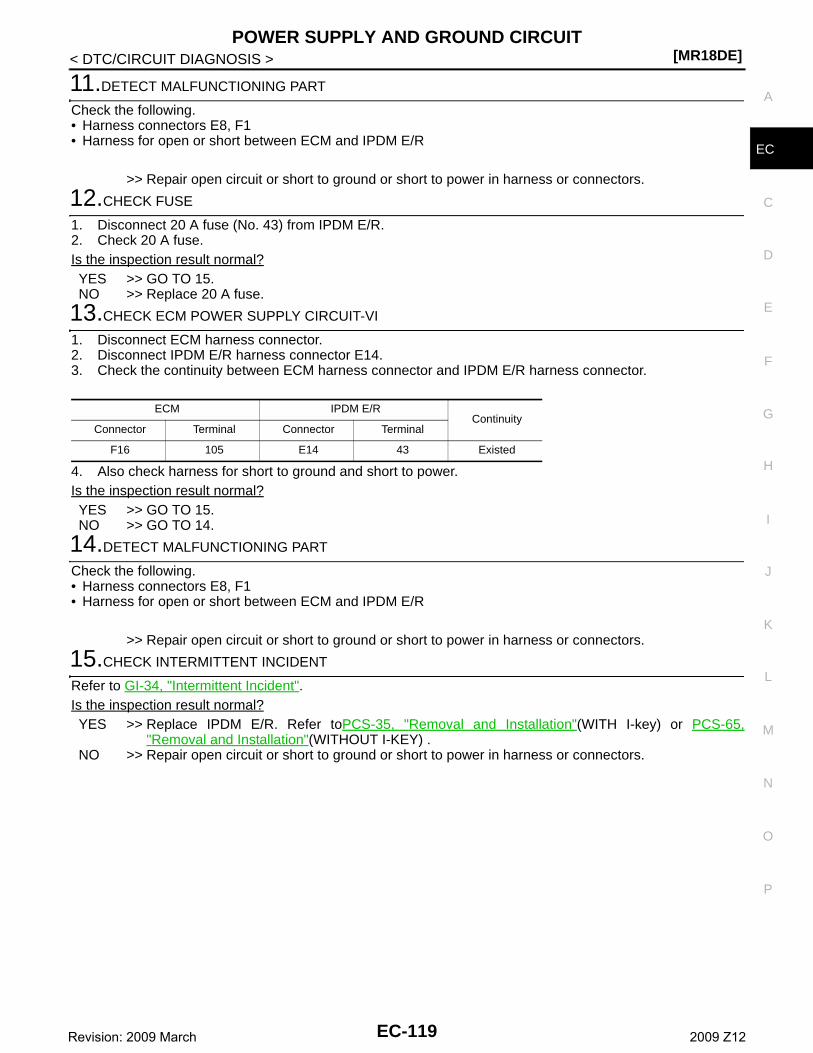
POWER SUPPLY AND GROUND CIRCUIT[MR18DE]
C
D
E
F
G
H
I
J
K
L
M
A
C
N
P
O
< DTC/CIRCUIT DIAGNOSIS >
E
11.DETECT MALFUNCTIONING PART
Check the following.• Harness connectors E8, F1• Harness for open or short between ECM and IPDM E/R
>> Repair open circuit or short to ground or short to power in harness or connectors.
12.CHECK FUSE
1. Disconnect 20 A fuse (No. 43) from IPDM E/R.2. Check 20 A fuse.Is the inspection result normal?YES >> GO TO 15.NO >> Replace 20 A fuse.
13.CHECK ECM POWER SUPPLY CIRCUIT-VI
1. Disconnect ECM harness connector.2. Disconnect IPDM E/R harness connector E14.3. Check the continuity between ECM harness connector and IPDM E/R harness connector.
4. Also check harness for short to ground and short to power.Is the inspection result normal?YES >> GO TO 15.NO >> GO TO 14.
14.DETECT MALFUNCTIONING PART
Check the following.• Harness connectors E8, F1• Harness for open or short between ECM and IPDM E/R
>> Repair open circuit or short to ground or short to power in harness or connectors.
15.CHECK INTERMITTENT INCIDENT
Refer to GI-34, "Intermittent Incident".Is the inspection result normal?YES >> Replace IPDM E/R. Refer toPCS-35, "Removal and Installation"(WITH I-key) or PCS-65,
"Removal and Installation"(WITHOUT I-KEY) .NO >> Repair open circuit or short to ground or short to power in harness or connectors.
ECM IPDM E/RContinuity
Connector Terminal Connector Terminal
F16 105 E14 43 Existed
EC-119Revision: 2009 March 2009 Z12
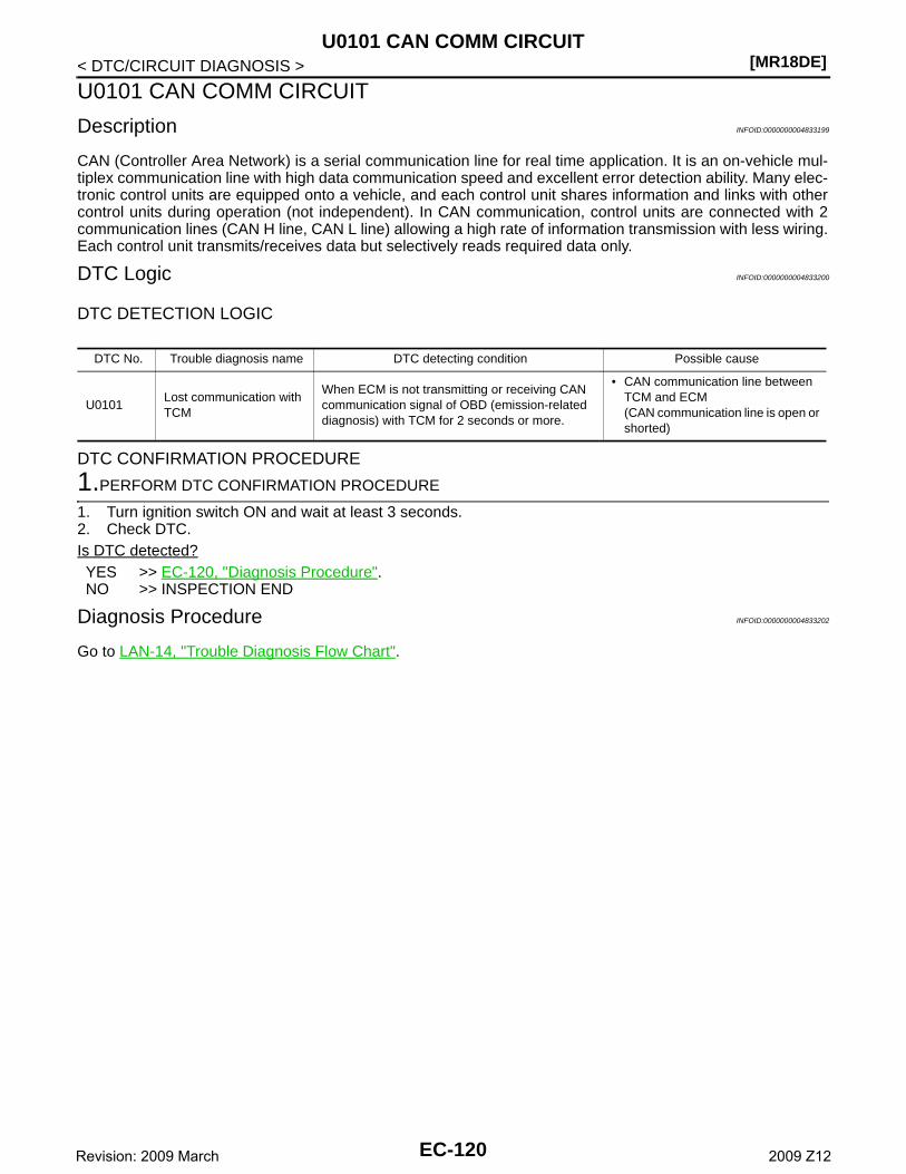
[MR18DE]U0101 CAN COMM CIRCUIT
< DTC/CIRCUIT DIAGNOSIS >
U0101 CAN COMM CIRCUIT
Description INFOID:0000000004833199
CAN (Controller Area Network) is a serial communication line for real time application. It is an on-vehicle mul-tiplex communication line with high data communication speed and excellent error detection ability. Many elec-tronic control units are equipped onto a vehicle, and each control unit shares information and links with othercontrol units during operation (not independent). In CAN communication, control units are connected with 2communication lines (CAN H line, CAN L line) allowing a high rate of information transmission with less wiring.Each control unit transmits/receives data but selectively reads required data only.
DTC Logic INFOID:0000000004833200
DTC DETECTION LOGIC
DTC CONFIRMATION PROCEDURE
1.PERFORM DTC CONFIRMATION PROCEDURE
1. Turn ignition switch ON and wait at least 3 seconds.2. Check DTC.Is DTC detected?YES >> EC-120, "Diagnosis Procedure".NO >> INSPECTION END
Diagnosis Procedure INFOID:0000000004833202
Go to LAN-14, "Trouble Diagnosis Flow Chart".
DTC No. Trouble diagnosis name DTC detecting condition Possible cause
U0101Lost communication with TCM
When ECM is not transmitting or receiving CAN communication signal of OBD (emission-related diagnosis) with TCM for 2 seconds or more.
• CAN communication line between TCM and ECM(CAN communication line is open or shorted)
EC-120Revision: 2009 March 2009 Z12
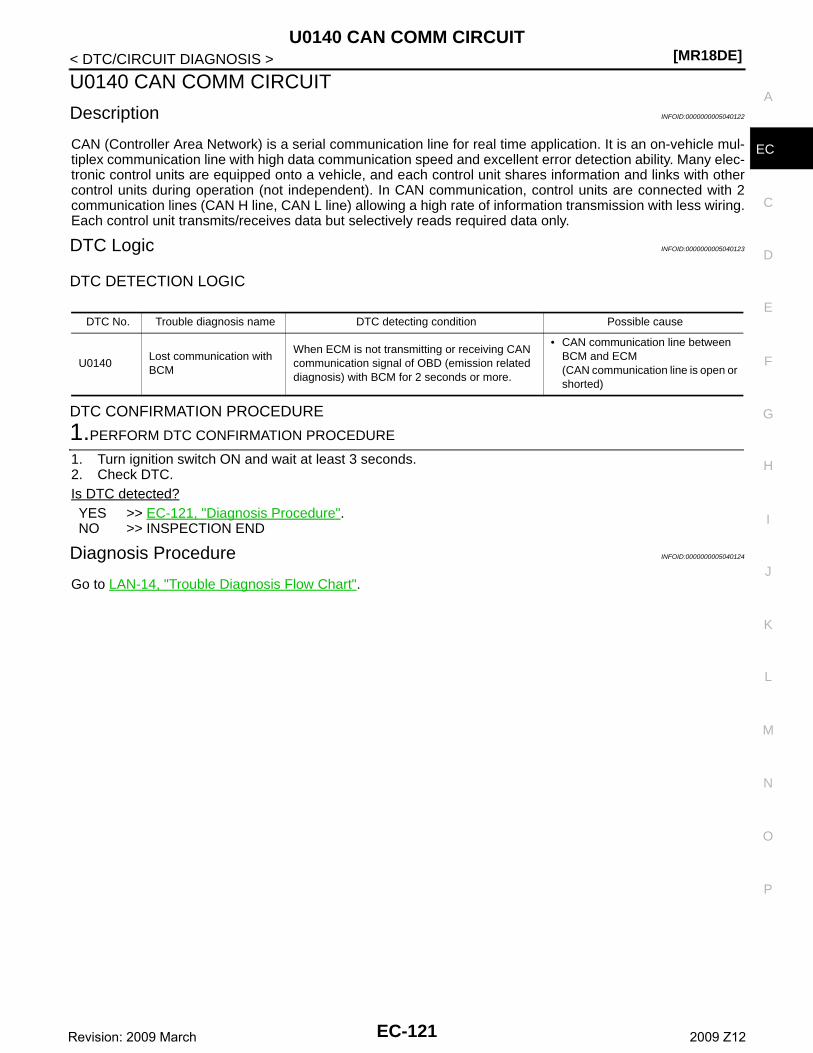
U0140 CAN COMM CIRCUIT[MR18DE]
C
D
E
F
G
H
I
J
K
L
M
A
C
N
P
O
< DTC/CIRCUIT DIAGNOSIS >
E
U0140 CAN COMM CIRCUIT
Description INFOID:0000000005040122
CAN (Controller Area Network) is a serial communication line for real time application. It is an on-vehicle mul-tiplex communication line with high data communication speed and excellent error detection ability. Many elec-tronic control units are equipped onto a vehicle, and each control unit shares information and links with othercontrol units during operation (not independent). In CAN communication, control units are connected with 2communication lines (CAN H line, CAN L line) allowing a high rate of information transmission with less wiring.Each control unit transmits/receives data but selectively reads required data only.
DTC Logic INFOID:0000000005040123
DTC DETECTION LOGIC
DTC CONFIRMATION PROCEDURE
1.PERFORM DTC CONFIRMATION PROCEDURE
1. Turn ignition switch ON and wait at least 3 seconds.2. Check DTC.Is DTC detected?YES >> EC-121, "Diagnosis Procedure".NO >> INSPECTION END
Diagnosis Procedure INFOID:0000000005040124
Go to LAN-14, "Trouble Diagnosis Flow Chart".
DTC No. Trouble diagnosis name DTC detecting condition Possible cause
U0140Lost communication with BCM
When ECM is not transmitting or receiving CAN communication signal of OBD (emission related diagnosis) with BCM for 2 seconds or more.
• CAN communication line between BCM and ECM(CAN communication line is open or shorted)
EC-121Revision: 2009 March 2009 Z12
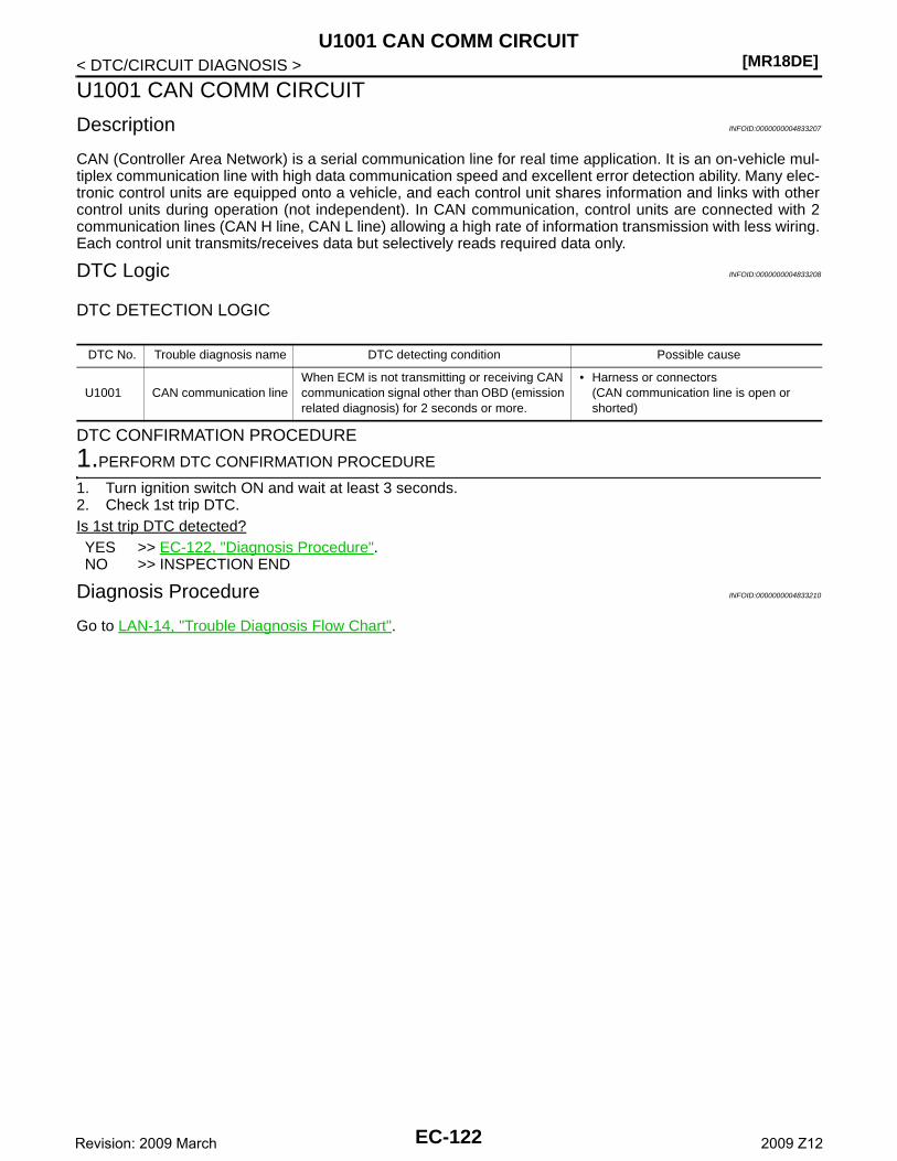
[MR18DE]U1001 CAN COMM CIRCUIT
< DTC/CIRCUIT DIAGNOSIS >
U1001 CAN COMM CIRCUIT
Description INFOID:0000000004833207
CAN (Controller Area Network) is a serial communication line for real time application. It is an on-vehicle mul-tiplex communication line with high data communication speed and excellent error detection ability. Many elec-tronic control units are equipped onto a vehicle, and each control unit shares information and links with othercontrol units during operation (not independent). In CAN communication, control units are connected with 2communication lines (CAN H line, CAN L line) allowing a high rate of information transmission with less wiring.Each control unit transmits/receives data but selectively reads required data only.
DTC Logic INFOID:0000000004833208
DTC DETECTION LOGIC
DTC CONFIRMATION PROCEDURE
1.PERFORM DTC CONFIRMATION PROCEDURE
1. Turn ignition switch ON and wait at least 3 seconds.2. Check 1st trip DTC.Is 1st trip DTC detected?YES >> EC-122, "Diagnosis Procedure".NO >> INSPECTION END
Diagnosis Procedure INFOID:0000000004833210
Go to LAN-14, "Trouble Diagnosis Flow Chart".
DTC No. Trouble diagnosis name DTC detecting condition Possible cause
U1001 CAN communication lineWhen ECM is not transmitting or receiving CAN communication signal other than OBD (emission related diagnosis) for 2 seconds or more.
• Harness or connectors(CAN communication line is open or shorted)
EC-122Revision: 2009 March 2009 Z12
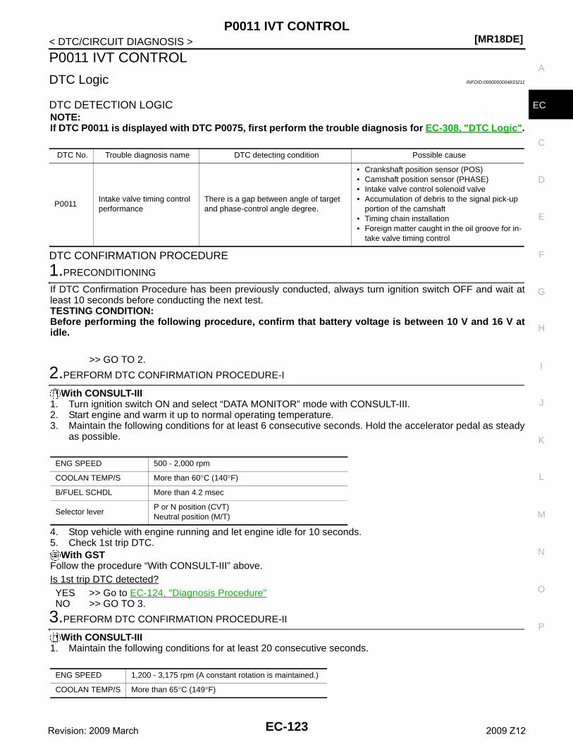
P0011 IVT CONTROL[MR18DE]
C
D
E
F
G
H
I
J
K
L
M
A
C
N
P
O
< DTC/CIRCUIT DIAGNOSIS >
E
P0011 IVT CONTROL
DTC Logic INFOID:0000000004833211
DTC DETECTION LOGICNOTE:If DTC P0011 is displayed with DTC P0075, first perform the trouble diagnosis for EC-308, "DTC Logic".
DTC CONFIRMATION PROCEDURE
1.PRECONDITIONING
If DTC Confirmation Procedure has been previously conducted, always turn ignition switch OFF and wait atleast 10 seconds before conducting the next test. TESTING CONDITION:Before performing the following procedure, confirm that battery voltage is between 10 V and 16 V atidle.
>> GO TO 2.
2.PERFORM DTC CONFIRMATION PROCEDURE-I
With CONSULT-III1. Turn ignition switch ON and select “DATA MONITOR” mode with CONSULT-III.2. Start engine and warm it up to normal operating temperature.3. Maintain the following conditions for at least 6 consecutive seconds. Hold the accelerator pedal as steady
as possible.
4. Stop vehicle with engine running and let engine idle for 10 seconds.5. Check 1st trip DTC.
With GSTFollow the procedure “With CONSULT-III” above.Is 1st trip DTC detected?YES >> Go to EC-124, "Diagnosis Procedure"NO >> GO TO 3.
3.PERFORM DTC CONFIRMATION PROCEDURE-II
With CONSULT-III1. Maintain the following conditions for at least 20 consecutive seconds.
DTC No. Trouble diagnosis name DTC detecting condition Possible cause
P0011Intake valve timing control performance
There is a gap between angle of target and phase-control angle degree.
• Crankshaft position sensor (POS)• Camshaft position sensor (PHASE)• Intake valve control solenoid valve• Accumulation of debris to the signal pick-up
portion of the camshaft• Timing chain installation• Foreign matter caught in the oil groove for in-
take valve timing control
ENG SPEED 500 - 2,000 rpm
COOLAN TEMP/S More than 60°C (140°F)
B/FUEL SCHDL More than 4.2 msec
Selector leverP or N position (CVT)Neutral position (M/T)
ENG SPEED 1,200 - 3,175 rpm (A constant rotation is maintained.)
COOLAN TEMP/S More than 65°C (149°F)
EC-123Revision: 2009 March 2009 Z12
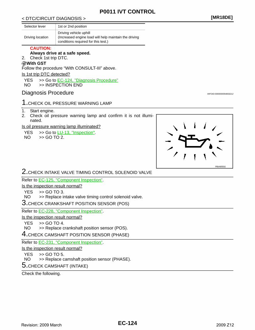
[MR18DE]P0011 IVT CONTROL
< DTC/CIRCUIT DIAGNOSIS >
CAUTION:Always drive at a safe speed.
2. Check 1st trip DTC.With GST
Follow the procedure “With CONSULT-III” above.Is 1st trip DTC detected?YES >> Go to EC-124, "Diagnosis Procedure"NO >> INSPECTION END
Diagnosis Procedure INFOID:0000000004833212
1.CHECK OIL PRESSURE WARNING LAMP
1. Start engine.2. Check oil pressure warning lamp and confirm it is not illumi-
nated.Is oil pressure warning lamp illuminated?YES >> Go to LU-13, "Inspection".NO >> GO TO 2.
2.CHECK INTAKE VALVE TIMING CONTROL SOLENOID VALVE
Refer to EC-125, "Component Inspection".Is the inspection result normal?YES >> GO TO 3.NO >> Replace intake valve timing control solenoid valve.
3.CHECK CRANKSHAFT POSITION SENSOR (POS)
Refer to EC-228, "Component Inspection".Is the inspection result normal?YES >> GO TO 4.NO >> Replace crankshaft position sensor (POS).
4.CHECK CAMSHAFT POSITION SENSOR (PHASE)
Refer to EC-231, "Component Inspection".Is the inspection result normal?YES >> GO TO 5.NO >> Replace camshaft position sensor (PHASE).
5.CHECK CAMSHAFT (INTAKE)
Check the following.
Selector lever 1st or 2nd position
Driving locationDriving vehicle uphill(Increased engine load will help maintain the driving conditions required for this test.)
PBIA8559J
EC-124Revision: 2009 March 2009 Z12
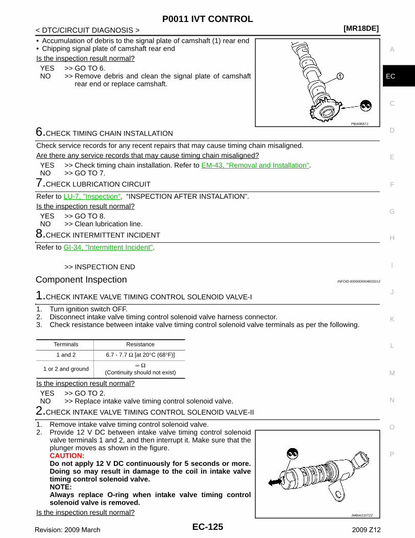
P0011 IVT CONTROL[MR18DE]
C
D
E
F
G
H
I
J
K
L
M
A
C
N
P
O
< DTC/CIRCUIT DIAGNOSIS >
E
• Accumulation of debris to the signal plate of camshaft (1) rear end• Chipping signal plate of camshaft rear endIs the inspection result normal?YES >> GO TO 6.NO >> Remove debris and clean the signal plate of camshaft
rear end or replace camshaft.
6.CHECK TIMING CHAIN INSTALLATION
Check service records for any recent repairs that may cause timing chain misaligned.Are there any service records that may cause timing chain misaligned?YES >> Check timing chain installation. Refer to EM-43, "Removal and Installation".NO >> GO TO 7.
7.CHECK LUBRICATION CIRCUIT
Refer to LU-7, "Inspection", “INSPECTION AFTER INSTALATION”.Is the inspection result normal?YES >> GO TO 8.NO >> Clean lubrication line.
8.CHECK INTERMITTENT INCIDENT
Refer to GI-34, "Intermittent Incident".
>> INSPECTION END
Component Inspection INFOID:0000000004833213
1.CHECK INTAKE VALVE TIMING CONTROL SOLENOID VALVE-I
1. Turn ignition switch OFF.2. Disconnect intake valve timing control solenoid valve harness connector.3. Check resistance between intake valve timing control solenoid valve terminals as per the following.
Is the inspection result normal?YES >> GO TO 2.NO >> Replace intake valve timing control solenoid valve.
2.CHECK INTAKE VALVE TIMING CONTROL SOLENOID VALVE-II
1. Remove intake valve timing control solenoid valve.2. Provide 12 V DC between intake valve timing control solenoid
valve terminals 1 and 2, and then interrupt it. Make sure that theplunger moves as shown in the figure.CAUTION:Do not apply 12 V DC continuously for 5 seconds or more.Doing so may result in damage to the coil in intake valvetiming control solenoid valve.NOTE:Always replace O-ring when intake valve timing controlsolenoid valve is removed.
Is the inspection result normal?
PBIA9557J
Terminals Resistance
1 and 2 6.7 - 7.7 Ω [at 20°C (68°F)]
1 or 2 and ground∞ Ω
(Continuity should not exist)
JMBIA2107ZZ
EC-125Revision: 2009 March 2009 Z12
[MR18DE]P0011 IVT CONTROL
< DTC/CIRCUIT DIAGNOSIS >YES >> INSPECTION ENDNO >> Replace intake valve timing control solenoid valve.
EC-126Revision: 2009 March 2009 Z12
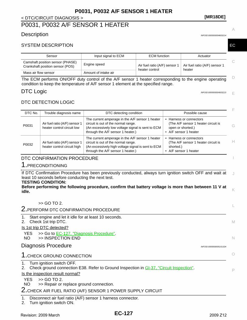
P0031, P0032 A/F SENSOR 1 HEATER[MR18DE]
C
D
E
F
G
H
I
J
K
L
M
A
C
N
P
O
< DTC/CIRCUIT DIAGNOSIS >
E
P0031, P0032 A/F SENSOR 1 HEATER
Description INFOID:0000000004833214
SYSTEM DESCRIPTION
The ECM performs ON/OFF duty control of the A/F sensor 1 heater corresponding to the engine operatingcondition to keep the temperature of A/F sensor 1 element at the specified range.
DTC Logic INFOID:0000000004833215
DTC DETECTION LOGIC
DTC CONFIRMATION PROCEDURE
1.PRECONDITIONING
If DTC Confirmation Procedure has been previously conducted, always turn ignition switch OFF and wait atleast 10 seconds before conducting the next test.TESTING CONDITION:Before performing the following procedure, confirm that battery voltage is more than between 11 V atidle.
>> GO TO 2.
2.PERFORM DTC CONFIRMATION PROCEDURE
1. Start engine and let it idle for at least 10 seconds.2. Check 1st trip DTC.Is 1st trip DTC detected?YES >> Go to EC-127, "Diagnosis Procedure".NO >> INSPECTION END
Diagnosis Procedure INFOID:0000000005151324
1.CHECK GROUND CONNECTION
1. Turn ignition switch OFF.2. Check ground connection E38. Refer to Ground Inspection in GI-37, "Circuit Inspection".Is the inspection result normal?YES >> GO TO 2.NO >> Repair or replace ground connection.
2.CHECK AIR FUEL RATIO (A/F) SENSOR 1 POWER SUPPLY CIRCUIT
1. Disconnect air fuel ratio (A/F) sensor 1 harness connector.2. Turn ignition switch ON.
Sensor Input signal to ECM ECM function Actuator
Camshaft position sensor (PHASE)Crankshaft position sensor (POS)
Engine speed Air fuel ratio (A/F) sensor 1 heater control
Air fuel ratio (A/F) sensor 1 heater
Mass air flow sensor Amount of intake air
DTC No. Trouble diagnosis name DTC detecting condition Possible cause
P0031Air fuel ratio (A/F) sensor 1 heater control circuit low
The current amperage in the A/F sensor 1 heater circuit is out of the normal range.(An excessively low voltage signal is sent to ECM through the A/F sensor 1 heater.)
• Harness or connectors(The A/F sensor 1 heater circuit is open or shorted.)
• A/F sensor 1 heater
P0032Air fuel ratio (A/F) sensor 1 heater control circuit high
The current amperage in the A/F sensor 1 heater circuit is out of the normal range.(An excessively high voltage signal is sent to ECM through the A/F sensor 1 heater.)
• Harness or connectors(The A/F sensor 1 heater circuit is shorted.)
• A/F sensor 1 heater
EC-127Revision: 2009 March 2009 Z12
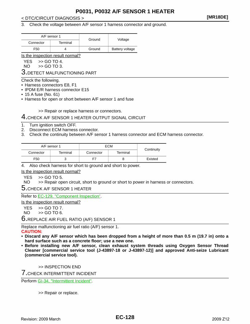
[MR18DE]P0031, P0032 A/F SENSOR 1 HEATER
< DTC/CIRCUIT DIAGNOSIS >3. Check the voltage between A/F sensor 1 harness connector and ground.
Is the inspection result normal?YES >> GO TO 4.NO >> GO TO 3.
3.DETECT MALFUNCTIONING PART
Check the following.• Harness connectors E8, F1• IPDM E/R harness connector E15• 15 A fuse (No. 61)• Harness for open or short between A/F sensor 1 and fuse
>> Repair or replace harness or connectors.
4.CHECK A/F SENSOR 1 HEATER OUTPUT SIGNAL CIRCUIT
1. Turn ignition switch OFF.2. Disconnect ECM harness connector.3. Check the continuity between A/F sensor 1 harness connector and ECM harness connector.
4. Also check harness for short to ground and short to power.Is the inspection result normal?YES >> GO TO 5.NO >> Repair open circuit, short to ground or short to power in harness or connectors.
5.CHECK A/F SENSOR 1 HEATER
Refer to EC-129, "Component Inspection".Is the inspection result normal?YES >> GO TO 7.NO >> GO TO 6.
6.REPLACE AIR FUEL RATIO (A/F) SENSOR 1
Replace malfunctioning air fuel ratio (A/F) sensor 1.CAUTION:• Discard any A/F sensor which has been dropped from a height of more than 0.5 m (19.7 in) onto a
hard surface such as a concrete floor; use a new one.• Before installing new A/F sensor, clean exhaust system threads using Oxygen Sensor Thread
Cleaner [commercial service tool (J-43897-18 or J-43897-12)] and approved Anti-seize Lubricant(commercial service tool).
>> INSPECTION END
7.CHECK INTERMITTENT INCIDENT
Perform GI-34, "Intermittent Incident".
>> Repair or replace.
A/F sensor 1Ground Voltage
Connector Terminal
F50 4 Ground Battery voltage
A/F sensor 1 ECMContinuity
Connector Terminal Connector Terminal
F50 3 F7 8 Existed
EC-128Revision: 2009 March 2009 Z12
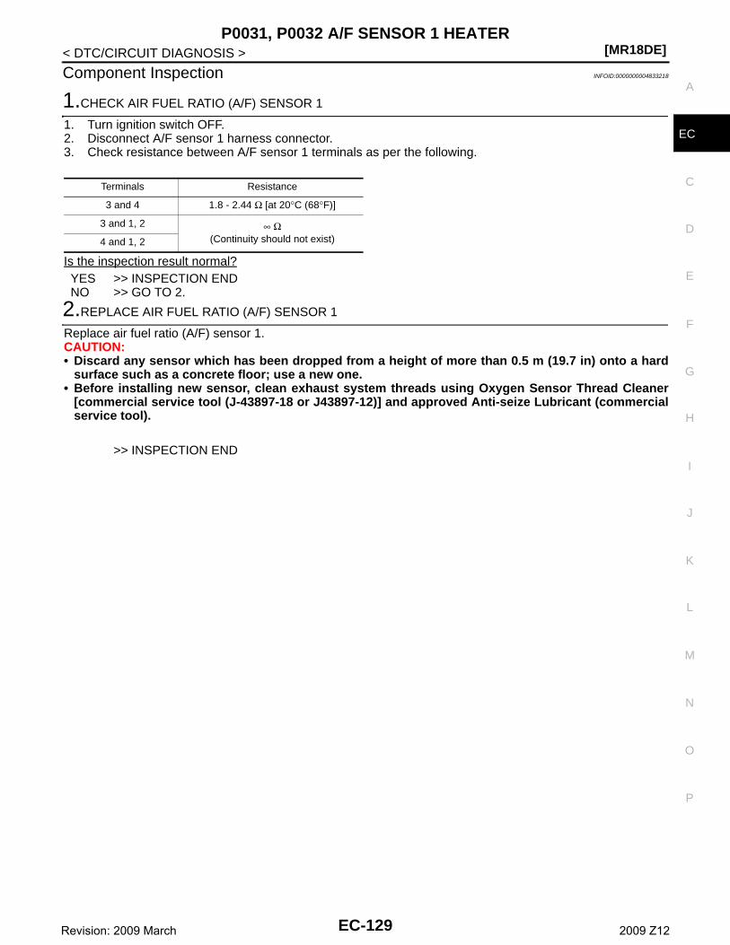
P0031, P0032 A/F SENSOR 1 HEATER[MR18DE]
C
D
E
F
G
H
I
J
K
L
M
A
C
N
P
O
< DTC/CIRCUIT DIAGNOSIS >
E
Component Inspection INFOID:0000000004833218
1.CHECK AIR FUEL RATIO (A/F) SENSOR 1
1. Turn ignition switch OFF.2. Disconnect A/F sensor 1 harness connector.3. Check resistance between A/F sensor 1 terminals as per the following.
Is the inspection result normal?YES >> INSPECTION ENDNO >> GO TO 2.
2.REPLACE AIR FUEL RATIO (A/F) SENSOR 1
Replace air fuel ratio (A/F) sensor 1.CAUTION:• Discard any sensor which has been dropped from a height of more than 0.5 m (19.7 in) onto a hard
surface such as a concrete floor; use a new one.• Before installing new sensor, clean exhaust system threads using Oxygen Sensor Thread Cleaner
[commercial service tool (J-43897-18 or J43897-12)] and approved Anti-seize Lubricant (commercialservice tool).
>> INSPECTION END
Terminals Resistance
3 and 4 1.8 - 2.44 Ω [at 20°C (68°F)]
3 and 1, 2 ∞ Ω(Continuity should not exist)4 and 1, 2
EC-129Revision: 2009 March 2009 Z12
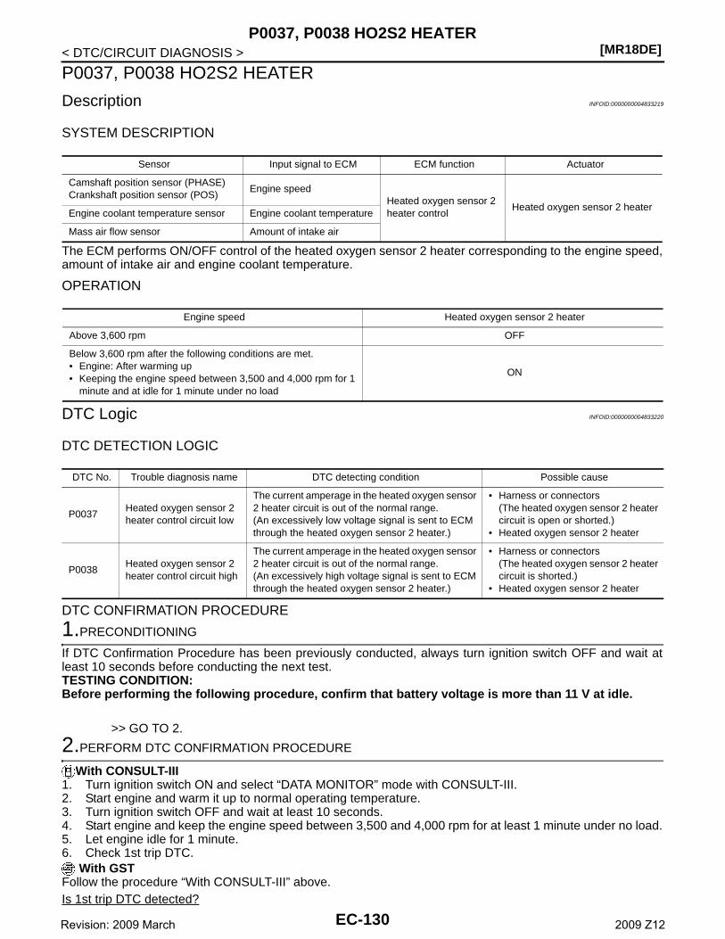
[MR18DE]P0037, P0038 HO2S2 HEATER
< DTC/CIRCUIT DIAGNOSIS >
P0037, P0038 HO2S2 HEATER
Description INFOID:0000000004833219
SYSTEM DESCRIPTION
The ECM performs ON/OFF control of the heated oxygen sensor 2 heater corresponding to the engine speed,amount of intake air and engine coolant temperature.
OPERATION
DTC Logic INFOID:0000000004833220
DTC DETECTION LOGIC
DTC CONFIRMATION PROCEDURE
1.PRECONDITIONING
If DTC Confirmation Procedure has been previously conducted, always turn ignition switch OFF and wait atleast 10 seconds before conducting the next test.TESTING CONDITION:Before performing the following procedure, confirm that battery voltage is more than 11 V at idle.
>> GO TO 2.
2.PERFORM DTC CONFIRMATION PROCEDURE
With CONSULT-III1. Turn ignition switch ON and select “DATA MONITOR” mode with CONSULT-III.2. Start engine and warm it up to normal operating temperature.3. Turn ignition switch OFF and wait at least 10 seconds.4. Start engine and keep the engine speed between 3,500 and 4,000 rpm for at least 1 minute under no load.5. Let engine idle for 1 minute.6. Check 1st trip DTC.
With GSTFollow the procedure “With CONSULT-III” above.Is 1st trip DTC detected?
Sensor Input signal to ECM ECM function Actuator
Camshaft position sensor (PHASE)Crankshaft position sensor (POS)
Engine speedHeated oxygen sensor 2 heater control
Heated oxygen sensor 2 heaterEngine coolant temperature sensor Engine coolant temperature
Mass air flow sensor Amount of intake air
Engine speed Heated oxygen sensor 2 heater
Above 3,600 rpm OFF
Below 3,600 rpm after the following conditions are met.• Engine: After warming up• Keeping the engine speed between 3,500 and 4,000 rpm for 1
minute and at idle for 1 minute under no load
ON
DTC No. Trouble diagnosis name DTC detecting condition Possible cause
P0037Heated oxygen sensor 2 heater control circuit low
The current amperage in the heated oxygen sensor 2 heater circuit is out of the normal range.(An excessively low voltage signal is sent to ECM through the heated oxygen sensor 2 heater.)
• Harness or connectors(The heated oxygen sensor 2 heater circuit is open or shorted.)
• Heated oxygen sensor 2 heater
P0038Heated oxygen sensor 2 heater control circuit high
The current amperage in the heated oxygen sensor 2 heater circuit is out of the normal range.(An excessively high voltage signal is sent to ECM through the heated oxygen sensor 2 heater.)
• Harness or connectors(The heated oxygen sensor 2 heater circuit is shorted.)
• Heated oxygen sensor 2 heater
EC-130Revision: 2009 March 2009 Z12
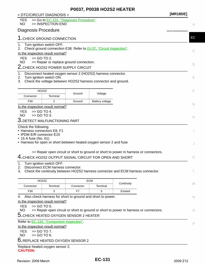
P0037, P0038 HO2S2 HEATER[MR18DE]
C
D
E
F
G
H
I
J
K
L
M
A
C
N
P
O
< DTC/CIRCUIT DIAGNOSIS >
E
YES >> Go to EC-131, "Diagnosis Procedure".NO >> INSPECTION END
Diagnosis Procedure INFOID:0000000004833222
1.CHECK GROUND CONNECTION
1. Turn ignition switch OFF.2. Check ground connection E38. Refer to GI-37, "Circuit Inspection".Is the inspection result normal?YES >> GO TO 2.NO >> Repair or replace ground connection.
2.CHECK HO2S2 POWER SUPPLY CIRCUIT
1. Disconnect heated oxygen sensor 2 (HO2S2) harness connector.2. Turn ignition switch ON.3. Check the voltage between HO2S2 harness connector and ground.
Is the inspection result normal?YES >> GO TO 4.NO >> GO TO 3.
3.DETECT MALFUNCTIONING PART
Check the following.• Harness connectors E8, F1• IPDM E/R connector E15• 15 A fuse (No. 61)• Harness for open or short between heated oxygen sensor 2 and fuse
>> Repair open circuit or short to ground or short to power in harness or connectors.
4.CHECK HO2S2 OUTPUT SIGNAL CIRCUIT FOR OPEN AND SHORT
1. Turn ignition switch OFF.2. Disconnect ECM harness connector.3. Check the continuity between HO2S2 harness connector and ECM harness connector.
4. Also check harness for short to ground and short to power.Is the inspection result normal?YES >> GO TO 5.NO >> Repair open circuit or short to ground or short to power in harness or connectors.
5.CHECK HEATED OXYGEN SENSOR 2 HEATER
Refer to EC-132, "Component Inspection".Is the inspection result normal?YES >> GO TO 7.NO >> GO TO 6.
6.REPLACE HEATED OXYGEN SENSOR 2
Replace heated oxygen sensor 2.CAUTION:
HO2S2Ground Voltage
Connector Terminal
F30 2 Ground Battery voltage
HO2S2 ECMContinuity
Connector Terminal Connector Terminal
F30 3 F7 5 Existed
EC-131Revision: 2009 March 2009 Z12
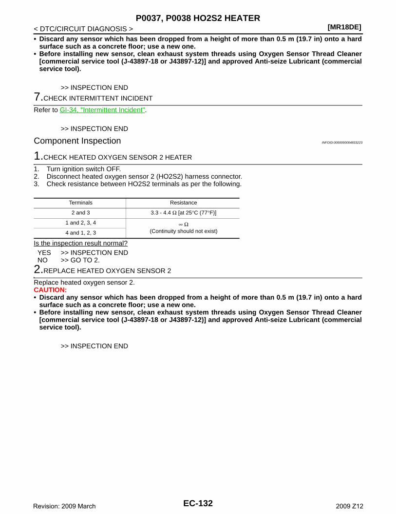
[MR18DE]P0037, P0038 HO2S2 HEATER
< DTC/CIRCUIT DIAGNOSIS >• Discard any sensor which has been dropped from a height of more than 0.5 m (19.7 in) onto a hard
surface such as a concrete floor; use a new one.• Before installing new sensor, clean exhaust system threads using Oxygen Sensor Thread Cleaner
[commercial service tool (J-43897-18 or J43897-12)] and approved Anti-seize Lubricant (commercialservice tool).
>> INSPECTION END
7.CHECK INTERMITTENT INCIDENT
Refer to GI-34, "Intermittent Incident".
>> INSPECTION END
Component Inspection INFOID:0000000004833223
1.CHECK HEATED OXYGEN SENSOR 2 HEATER
1. Turn ignition switch OFF.2. Disconnect heated oxygen sensor 2 (HO2S2) harness connector.3. Check resistance between HO2S2 terminals as per the following.
Is the inspection result normal?YES >> INSPECTION ENDNO >> GO TO 2.
2.REPLACE HEATED OXYGEN SENSOR 2
Replace heated oxygen sensor 2.CAUTION:• Discard any sensor which has been dropped from a height of more than 0.5 m (19.7 in) onto a hard
surface such as a concrete floor; use a new one.• Before installing new sensor, clean exhaust system threads using Oxygen Sensor Thread Cleaner
[commercial service tool (J-43897-18 or J43897-12)] and approved Anti-seize Lubricant (commercialservice tool).
>> INSPECTION END
Terminals Resistance
2 and 3 3.3 - 4.4 Ω [at 25°C (77°F)]
1 and 2, 3, 4 ∞ Ω(Continuity should not exist)4 and 1, 2, 3
EC-132Revision: 2009 March 2009 Z12
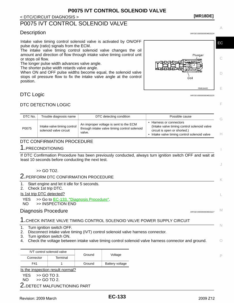
P0075 IVT CONTROL SOLENOID VALVE[MR18DE]
C
D
E
F
G
H
I
J
K
L
M
A
C
N
P
O
< DTC/CIRCUIT DIAGNOSIS >
E
P0075 IVT CONTROL SOLENOID VALVE
Description INFOID:0000000004833224
Intake valve timing control solenoid valve is activated by ON/OFFpulse duty (ratio) signals from the ECM.The intake valve timing control solenoid valve changes the oilamount and direction of flow through intake valve timing control unitor stops oil flow.The longer pulse width advances valve angle.The shorter pulse width retards valve angle.When ON and OFF pulse widths become equal, the solenoid valvestops oil pressure flow to fix the intake valve angle at the controlposition.
DTC Logic INFOID:0000000004833225
DTC DETECTION LOGIC
DTC CONFIRMATION PROCEDURE
1.PRECONDITIONING
If DTC Confirmation Procedure has been previously conducted, always turn ignition switch OFF and wait atleast 10 seconds before conducting the next test.
>> GO TO2.
2.PERFORM DTC CONFIRMATION PROCEDURE
1. Start engine and let it idle for 5 seconds.2. Check 1st trip DTC.Is 1st trip DTC detected?YES >> Go to EC-133, "Diagnosis Procedure".NO >> INSPECTION END
Diagnosis Procedure INFOID:0000000004833227
1.CHECK INTAKE VALVE TIMING CONTROL SOLENOID VALVE POWER SUPPLY CIRCUIT
1. Turn ignition switch OFF.2. Disconnect intake valve timing (IVT) control solenoid valve harness connector.3. Turn ignition switch ON.4. Check the voltage between intake valve timing control solenoid valve harness connector and ground.
Is the inspection result normal?YES >> GO TO 3.NO >> GO TO 2.
2.DETECT MALFUNCTIONING PART
PBIB1842E
DTC No. Trouble diagnosis name DTC detecting condition Possible cause
P0075Intake valve timing control solenoid valve circuit
An improper voltage is sent to the ECM through intake valve timing control solenoid valve.
• Harness or connectors(Intake valve timing control solenoid valve circuit is open or shorted.)
• Intake valve timing control solenoid valve
IVT control solenoid valveGround Voltage
Connector Terminal
F41 1 Ground Battery voltage
EC-133Revision: 2009 March 2009 Z12
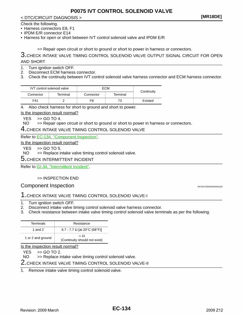
[MR18DE]P0075 IVT CONTROL SOLENOID VALVE
< DTC/CIRCUIT DIAGNOSIS >Check the following.• Harness connectors E8, F1• IPDM E/R connector E14• Harness for open or short between IVT control solenoid valve and IPDM E/R
>> Repair open circuit or short to ground or short to power in harness or connectors.
3.CHECK INTAKE VALVE TIMING CONTROL SOLENOID VALVE OUTPUT SIGNAL CIRCUIT FOR OPENAND SHORT
1. Turn ignition switch OFF.2. Disconnect ECM harness connector.3. Check the continuity between IVT control solenoid valve harness connector and ECM harness connector.
4. Also check harness for short to ground and short to power. Is the inspection result normal?YES >> GO TO 4.NO >> Repair open circuit or short to ground or short to power in harness or connectors.
4.CHECK INTAKE VALVE TIMING CONTROL SOLENOID VALVE
Refer to EC-134, "Component Inspection".Is the inspection result normal?YES >> GO TO 5.NO >> Replace intake valve timing control solenoid valve.
5.CHECK INTERMITTENT INCIDENT
Refer to GI-34, "Intermittent Incident".
>> INSPECTION END
Component Inspection INFOID:0000000004833228
1.CHECK INTAKE VALVE TIMING CONTROL SOLENOID VALVE-I
1. Turn ignition switch OFF.2. Disconnect intake valve timing control solenoid valve harness connector.3. Check resistance between intake valve timing control solenoid valve terminals as per the following.
Is the inspection result normal?YES >> GO TO 2.NO >> Replace intake valve timing control solenoid valve.
2.CHECK INTAKE VALVE TIMING CONTROL SOLENOID VALVE-II
1. Remove intake valve timing control solenoid valve.
IVT control solenoid valve ECMContinuity
Connector Terminal Connector Terminal
F41 2 F8 73 Existed
Terminals Resistance
1 and 2 6.7 - 7.7 Ω [at 20°C (68°F)]
1 or 2 and ground∞ Ω
(Continuity should not exist)
EC-134Revision: 2009 March 2009 Z12
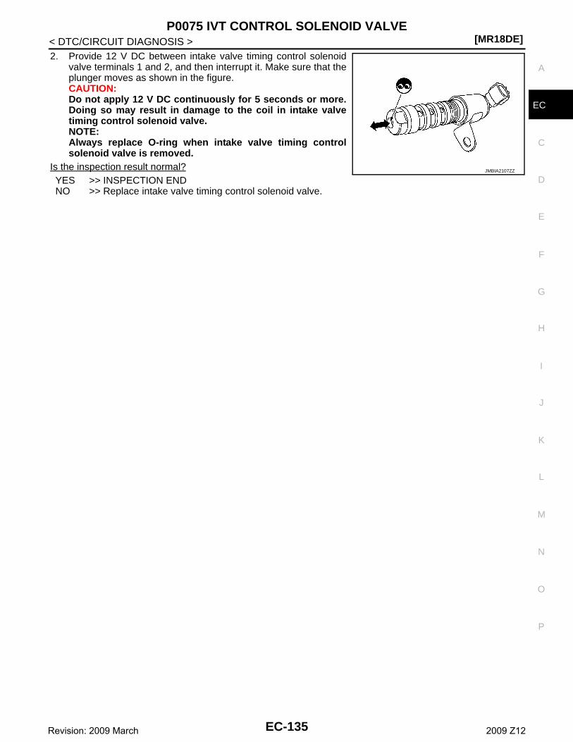
P0075 IVT CONTROL SOLENOID VALVE[MR18DE]
C
D
E
F
G
H
I
J
K
L
M
A
C
N
P
O
< DTC/CIRCUIT DIAGNOSIS >
E
2. Provide 12 V DC between intake valve timing control solenoidvalve terminals 1 and 2, and then interrupt it. Make sure that theplunger moves as shown in the figure.CAUTION:Do not apply 12 V DC continuously for 5 seconds or more.Doing so may result in damage to the coil in intake valvetiming control solenoid valve.NOTE:Always replace O-ring when intake valve timing controlsolenoid valve is removed.
Is the inspection result normal?YES >> INSPECTION ENDNO >> Replace intake valve timing control solenoid valve.
JMBIA2107ZZ
EC-135Revision: 2009 March 2009 Z12
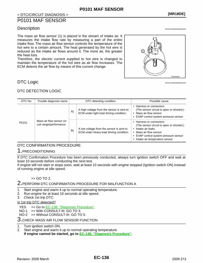
[MR18DE]P0101 MAF SENSOR
< DTC/CIRCUIT DIAGNOSIS >
P0101 MAF SENSOR
Description INFOID:0000000004833229
The mass air flow sensor (1) is placed in the stream of intake air. Itmeasures the intake flow rate by measuring a part of the entireintake flow. The mass air flow sensor controls the temperature of thehot wire to a certain amount. The heat generated by the hot wire isreduced as the intake air flows around it. The more air, the greaterthe heat loss. Therefore, the electric current supplied to hot wire is changed tomaintain the temperature of the hot wire as air flow increases. TheECM detects the air flow by means of this current change.
DTC Logic INFOID:0000000004833230
DTC DETECTION LOGIC
DTC CONFIRMATION PROCEDURE
1.PRECONDITIONING
If DTC Confirmation Procedure has been previously conducted, always turn ignition switch OFF and wait atleast 10 seconds before conducting the next test.If engine will not start or stops soon, wait at least 10 seconds with engine stopped (Ignition switch ON) insteadof running engine at idle speed.
>> GO TO 2.
2.PERFORM DTC CONFIRMATION PROCEDURE FOR MALFUNCTION A
1. Start engine and warm it up to normal operating temperature.2. Run engine for at least 10 seconds at idle speed.3. Check 1st trip DTC.Is 1st trip DTC detected?YES >> Go to EC-138, "Diagnosis Procedure".NO-1 >> With CONSULT-III: GO TO 3.NO-2 >> Without CONSULT-III: GO TO 5.
3.CHECK MASS AIR FLOW SENSOR FUNCTION
1. Turn ignition switch ON.2. Start engine and warm it up to normal operating temperature.
If engine cannot be started, go to EC-138, "Diagnosis Procedure".
PBIA9559J
DTC No. Trouble diagnosis name DTC detecting condition Possible cause
P0101Mass air flow sensor cir-cuit range/performance
A)A high voltage from the sensor is sent to ECM under light load driving condition.
• Harness or connectors(The sensor circuit is open or shorted.)
• Mass air flow sensor• EVAP control system pressure sensor
B)A low voltage from the sensor is sent to ECM under heavy load driving condition.
• Harness or connectors(The sensor circuit is open or shorted.)
• Intake air leaks• Mass air flow sensor• EVAP control system pressure sensor• Intake air temperature sensor
EC-136Revision: 2009 March 2009 Z12
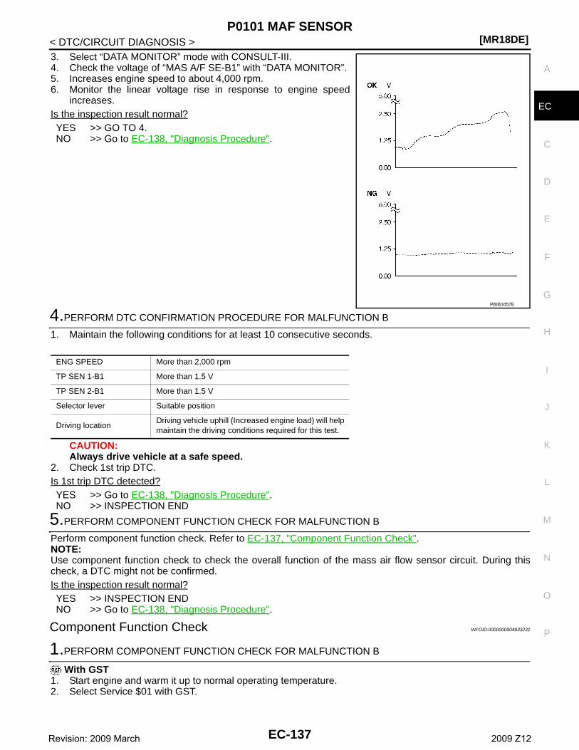
P0101 MAF SENSOR[MR18DE]
C
D
E
F
G
H
I
J
K
L
M
A
C
N
P
O
< DTC/CIRCUIT DIAGNOSIS >
E
3. Select “DATA MONITOR” mode with CONSULT-III.4. Check the voltage of “MAS A/F SE-B1” with “DATA MONITOR”.5. Increases engine speed to about 4,000 rpm.6. Monitor the linear voltage rise in response to engine speed
increases.Is the inspection result normal?YES >> GO TO 4.NO >> Go to EC-138, "Diagnosis Procedure".
4.PERFORM DTC CONFIRMATION PROCEDURE FOR MALFUNCTION B
1. Maintain the following conditions for at least 10 consecutive seconds.
CAUTION:Always drive vehicle at a safe speed.
2. Check 1st trip DTC.Is 1st trip DTC detected?YES >> Go to EC-138, "Diagnosis Procedure".NO >> INSPECTION END
5.PERFORM COMPONENT FUNCTION CHECK FOR MALFUNCTION B
Perform component function check. Refer to EC-137, "Component Function Check".NOTE:Use component function check to check the overall function of the mass air flow sensor circuit. During thischeck, a DTC might not be confirmed.Is the inspection result normal?YES >> INSPECTION ENDNO >> Go to EC-138, "Diagnosis Procedure".
Component Function Check INFOID:0000000004833231
1.PERFORM COMPONENT FUNCTION CHECK FOR MALFUNCTION B
With GST1. Start engine and warm it up to normal operating temperature.2. Select Service $01 with GST.
PBIB3457E
ENG SPEED More than 2,000 rpm
TP SEN 1-B1 More than 1.5 V
TP SEN 2-B1 More than 1.5 V
Selector lever Suitable position
Driving locationDriving vehicle uphill (Increased engine load) will help maintain the driving conditions required for this test.
EC-137Revision: 2009 March 2009 Z12
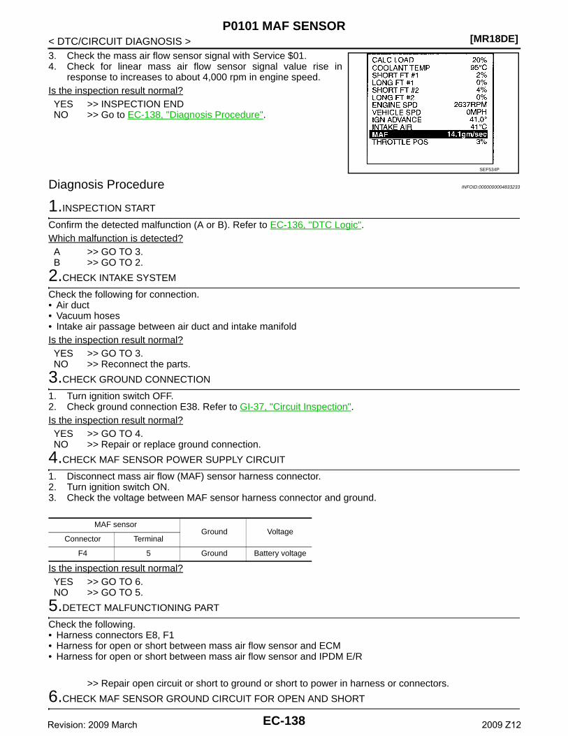
[MR18DE]P0101 MAF SENSOR
< DTC/CIRCUIT DIAGNOSIS >3. Check the mass air flow sensor signal with Service $01.4. Check for linear mass air flow sensor signal value rise in
response to increases to about 4,000 rpm in engine speed.Is the inspection result normal?YES >> INSPECTION ENDNO >> Go to EC-138, "Diagnosis Procedure".
Diagnosis Procedure INFOID:0000000004833233
1.INSPECTION START
Confirm the detected malfunction (A or B). Refer to EC-136, "DTC Logic".Which malfunction is detected?A >> GO TO 3.B >> GO TO 2.
2.CHECK INTAKE SYSTEM
Check the following for connection.• Air duct• Vacuum hoses• Intake air passage between air duct and intake manifoldIs the inspection result normal?YES >> GO TO 3.NO >> Reconnect the parts.
3.CHECK GROUND CONNECTION
1. Turn ignition switch OFF.2. Check ground connection E38. Refer to GI-37, "Circuit Inspection".Is the inspection result normal?YES >> GO TO 4.NO >> Repair or replace ground connection.
4.CHECK MAF SENSOR POWER SUPPLY CIRCUIT
1. Disconnect mass air flow (MAF) sensor harness connector.2. Turn ignition switch ON.3. Check the voltage between MAF sensor harness connector and ground.
Is the inspection result normal?YES >> GO TO 6.NO >> GO TO 5.
5.DETECT MALFUNCTIONING PART
Check the following.• Harness connectors E8, F1• Harness for open or short between mass air flow sensor and ECM• Harness for open or short between mass air flow sensor and IPDM E/R
>> Repair open circuit or short to ground or short to power in harness or connectors.
6.CHECK MAF SENSOR GROUND CIRCUIT FOR OPEN AND SHORT
SEF534P
MAF sensorGround Voltage
Connector Terminal
F4 5 Ground Battery voltage
EC-138Revision: 2009 March 2009 Z12
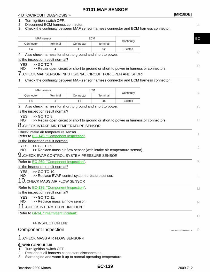
P0101 MAF SENSOR[MR18DE]
C
D
E
F
G
H
I
J
K
L
M
A
C
N
P
O
< DTC/CIRCUIT DIAGNOSIS >
E
1. Turn ignition switch OFF.2. Disconnect ECM harness connector.3. Check the continuity between MAF sensor harness connector and ECM harness connector.
4. Also check harness for short to ground and short to power.Is the inspection result normal?YES >> GO TO 7.NO >> Repair open circuit or short to ground or short to power in harness or connectors.
7.CHECK MAF SENSOR INPUT SIGNAL CIRCUIT FOR OPEN AND SHORT
1. Check the continuity between MAF sensor harness connector and ECM harness connector.
2. Also check harness for short to ground and short to power.Is the inspection result normal?YES >> GO TO 8.NO >> Repair open circuit or short to ground or short to power in harness or connectors.
8.CHECK INTAKE AIR TEMPERATURE SENSOR
Check intake air temperature sensor.Refer to EC-149, "Component Inspection".Is the inspection result normal?YES >> GO TO 9.NO >> Replace mass air flow sensor (with intake air temperature sensor).
9.CHECK EVAP CONTROL SYSTEM PRESSURE SENSOR
Refer to EC-269, "Component Inspection".Is the inspection result normal?YES >> GO TO 10.NO >> Replace EVAP control system pressure sensor.
10.CHECK MASS AIR FLOW SENSOR
Refer to EC-139, "Component Inspection".Is the inspection result normal?YES >> GO TO 11.NO >> Replace mass air flow sensor.
11.CHECK INTERMITTENT INCIDENT
Refer to GI-34, "Intermittent Incident".
>> INSPECTION END
Component Inspection INFOID:0000000004833234
1.CHECK MASS AIR FLOW SENSOR-I
With CONSULT-III1. Turn ignition switch OFF.2. Reconnect all harness connectors disconnected.3. Start engine and warm it up to normal operating temperature.
MAF sensor ECMContinuity
Connector Terminal Connector Terminal
F4 4 F8 52 Existed
MAF sensor ECMContinuity
Connector Terminal Connector Terminal
F4 3 F8 45 Existed
EC-139Revision: 2009 March 2009 Z12
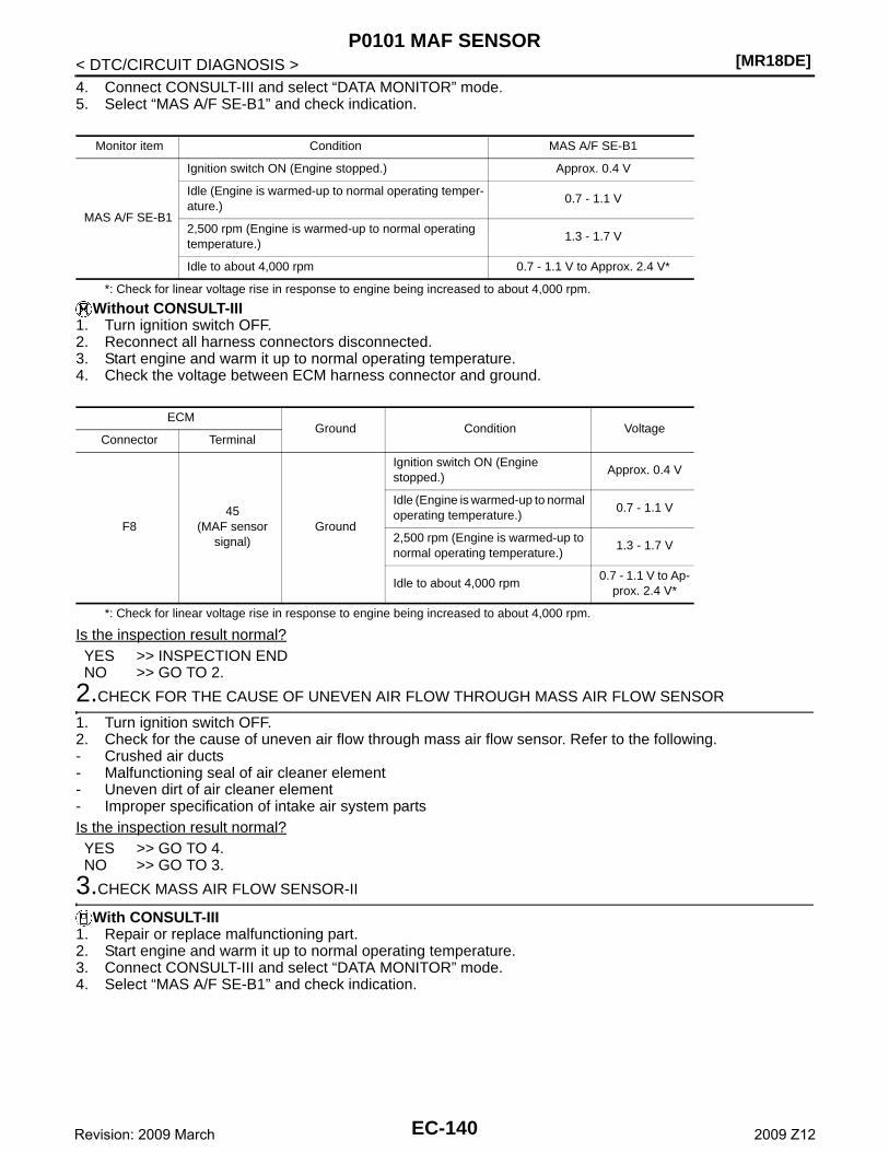
[MR18DE]P0101 MAF SENSOR
< DTC/CIRCUIT DIAGNOSIS >4. Connect CONSULT-III and select “DATA MONITOR” mode.5. Select “MAS A/F SE-B1” and check indication.
*: Check for linear voltage rise in response to engine being increased to about 4,000 rpm.
Without CONSULT-III1. Turn ignition switch OFF.2. Reconnect all harness connectors disconnected.3. Start engine and warm it up to normal operating temperature.4. Check the voltage between ECM harness connector and ground.
*: Check for linear voltage rise in response to engine being increased to about 4,000 rpm.
Is the inspection result normal?YES >> INSPECTION ENDNO >> GO TO 2.
2.CHECK FOR THE CAUSE OF UNEVEN AIR FLOW THROUGH MASS AIR FLOW SENSOR
1. Turn ignition switch OFF.2. Check for the cause of uneven air flow through mass air flow sensor. Refer to the following.- Crushed air ducts- Malfunctioning seal of air cleaner element- Uneven dirt of air cleaner element- Improper specification of intake air system partsIs the inspection result normal?YES >> GO TO 4.NO >> GO TO 3.
3.CHECK MASS AIR FLOW SENSOR-II
With CONSULT-III1. Repair or replace malfunctioning part.2. Start engine and warm it up to normal operating temperature.3. Connect CONSULT-III and select “DATA MONITOR” mode.4. Select “MAS A/F SE-B1” and check indication.
Monitor item Condition MAS A/F SE-B1
MAS A/F SE-B1
Ignition switch ON (Engine stopped.) Approx. 0.4 V
Idle (Engine is warmed-up to normal operating temper-ature.)
0.7 - 1.1 V
2,500 rpm (Engine is warmed-up to normal operating temperature.)
1.3 - 1.7 V
Idle to about 4,000 rpm 0.7 - 1.1 V to Approx. 2.4 V*
ECMGround Condition Voltage
Connector Terminal
F845
(MAF sensor signal)
Ground
Ignition switch ON (Engine stopped.)
Approx. 0.4 V
Idle (Engine is warmed-up to normal operating temperature.)
0.7 - 1.1 V
2,500 rpm (Engine is warmed-up to normal operating temperature.)
1.3 - 1.7 V
Idle to about 4,000 rpm0.7 - 1.1 V to Ap-
prox. 2.4 V*
EC-140Revision: 2009 March 2009 Z12
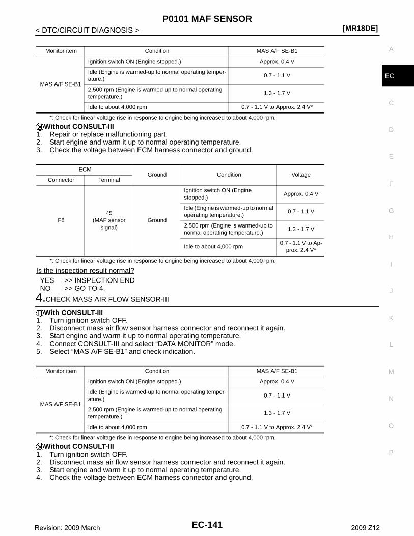
P0101 MAF SENSOR[MR18DE]
C
D
E
F
G
H
I
J
K
L
M
A
C
N
P
O
< DTC/CIRCUIT DIAGNOSIS >
E
*: Check for linear voltage rise in response to engine being increased to about 4,000 rpm.
Without CONSULT-III1. Repair or replace malfunctioning part.2. Start engine and warm it up to normal operating temperature.3. Check the voltage between ECM harness connector and ground.
*: Check for linear voltage rise in response to engine being increased to about 4,000 rpm.
Is the inspection result normal?YES >> INSPECTION ENDNO >> GO TO 4.
4.CHECK MASS AIR FLOW SENSOR-III
With CONSULT-III1. Turn ignition switch OFF.2. Disconnect mass air flow sensor harness connector and reconnect it again.3. Start engine and warm it up to normal operating temperature.4. Connect CONSULT-III and select “DATA MONITOR” mode.5. Select “MAS A/F SE-B1” and check indication.
*: Check for linear voltage rise in response to engine being increased to about 4,000 rpm.
Without CONSULT-III1. Turn ignition switch OFF.2. Disconnect mass air flow sensor harness connector and reconnect it again.3. Start engine and warm it up to normal operating temperature.4. Check the voltage between ECM harness connector and ground.
Monitor item Condition MAS A/F SE-B1
MAS A/F SE-B1
Ignition switch ON (Engine stopped.) Approx. 0.4 V
Idle (Engine is warmed-up to normal operating temper-ature.)
0.7 - 1.1 V
2,500 rpm (Engine is warmed-up to normal operating temperature.)
1.3 - 1.7 V
Idle to about 4,000 rpm 0.7 - 1.1 V to Approx. 2.4 V*
ECMGround Condition Voltage
Connector Terminal
F845
(MAF sensor signal)
Ground
Ignition switch ON (Engine stopped.)
Approx. 0.4 V
Idle (Engine is warmed-up to normal operating temperature.)
0.7 - 1.1 V
2,500 rpm (Engine is warmed-up to normal operating temperature.)
1.3 - 1.7 V
Idle to about 4,000 rpm0.7 - 1.1 V to Ap-
prox. 2.4 V*
Monitor item Condition MAS A/F SE-B1
MAS A/F SE-B1
Ignition switch ON (Engine stopped.) Approx. 0.4 V
Idle (Engine is warmed-up to normal operating temper-ature.)
0.7 - 1.1 V
2,500 rpm (Engine is warmed-up to normal operating temperature.)
1.3 - 1.7 V
Idle to about 4,000 rpm 0.7 - 1.1 V to Approx. 2.4 V*
EC-141Revision: 2009 March 2009 Z12
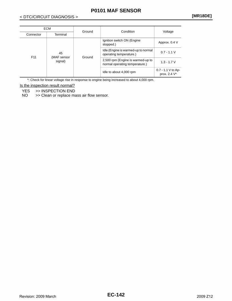
[MR18DE]P0101 MAF SENSOR
< DTC/CIRCUIT DIAGNOSIS >
*: Check for linear voltage rise in response to engine being increased to about 4,000 rpm.
Is the inspection result normal?YES >> INSPECTION ENDNO >> Clean or replace mass air flow sensor.
ECMGround Condition Voltage
Connector Terminal
F1145
(MAF sensor signal)
Ground
Ignition switch ON (Engine stopped.)
Approx. 0.4 V
Idle (Engine is warmed-up to normal operating temperature.)
0.7 - 1.1 V
2,500 rpm (Engine is warmed-up to normal operating temperature.)
1.3 - 1.7 V
Idle to about 4,000 rpm0.7 - 1.1 V to Ap-
prox. 2.4 V*
EC-142Revision: 2009 March 2009 Z12
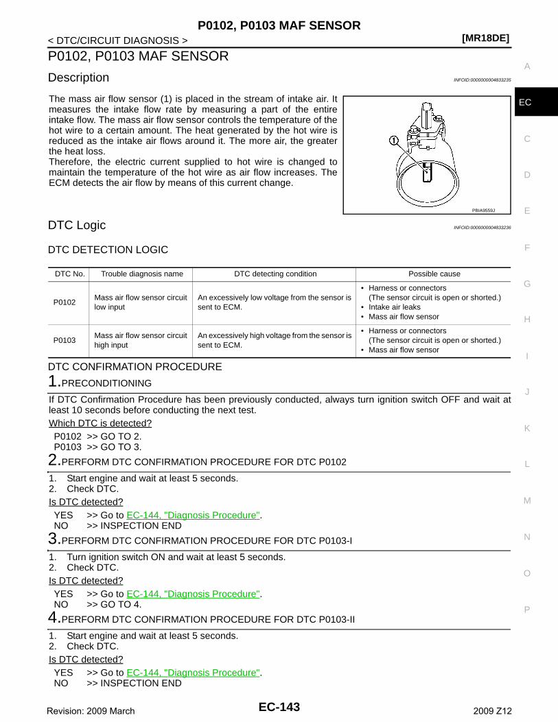
P0102, P0103 MAF SENSOR[MR18DE]
C
D
E
F
G
H
I
J
K
L
M
A
C
N
P
O
< DTC/CIRCUIT DIAGNOSIS >
E
P0102, P0103 MAF SENSOR
Description INFOID:0000000004833235
The mass air flow sensor (1) is placed in the stream of intake air. Itmeasures the intake flow rate by measuring a part of the entireintake flow. The mass air flow sensor controls the temperature of thehot wire to a certain amount. The heat generated by the hot wire isreduced as the intake air flows around it. The more air, the greaterthe heat loss. Therefore, the electric current supplied to hot wire is changed tomaintain the temperature of the hot wire as air flow increases. TheECM detects the air flow by means of this current change.
DTC Logic INFOID:0000000004833236
DTC DETECTION LOGIC
DTC CONFIRMATION PROCEDURE
1.PRECONDITIONING
If DTC Confirmation Procedure has been previously conducted, always turn ignition switch OFF and wait atleast 10 seconds before conducting the next test.Which DTC is detected?P0102 >> GO TO 2.P0103 >> GO TO 3.
2.PERFORM DTC CONFIRMATION PROCEDURE FOR DTC P0102
1. Start engine and wait at least 5 seconds.2. Check DTC.Is DTC detected?YES >> Go to EC-144, "Diagnosis Procedure".NO >> INSPECTION END
3.PERFORM DTC CONFIRMATION PROCEDURE FOR DTC P0103-I
1. Turn ignition switch ON and wait at least 5 seconds.2. Check DTC.Is DTC detected?YES >> Go to EC-144, "Diagnosis Procedure".NO >> GO TO 4.
4.PERFORM DTC CONFIRMATION PROCEDURE FOR DTC P0103-II
1. Start engine and wait at least 5 seconds.2. Check DTC.Is DTC detected?YES >> Go to EC-144, "Diagnosis Procedure".NO >> INSPECTION END
PBIA9559J
DTC No. Trouble diagnosis name DTC detecting condition Possible cause
P0102Mass air flow sensor circuit low input
An excessively low voltage from the sensor is sent to ECM.
• Harness or connectors(The sensor circuit is open or shorted.)
• Intake air leaks• Mass air flow sensor
P0103Mass air flow sensor circuit high input
An excessively high voltage from the sensor is sent to ECM.
• Harness or connectors(The sensor circuit is open or shorted.)
• Mass air flow sensor
EC-143Revision: 2009 March 2009 Z12
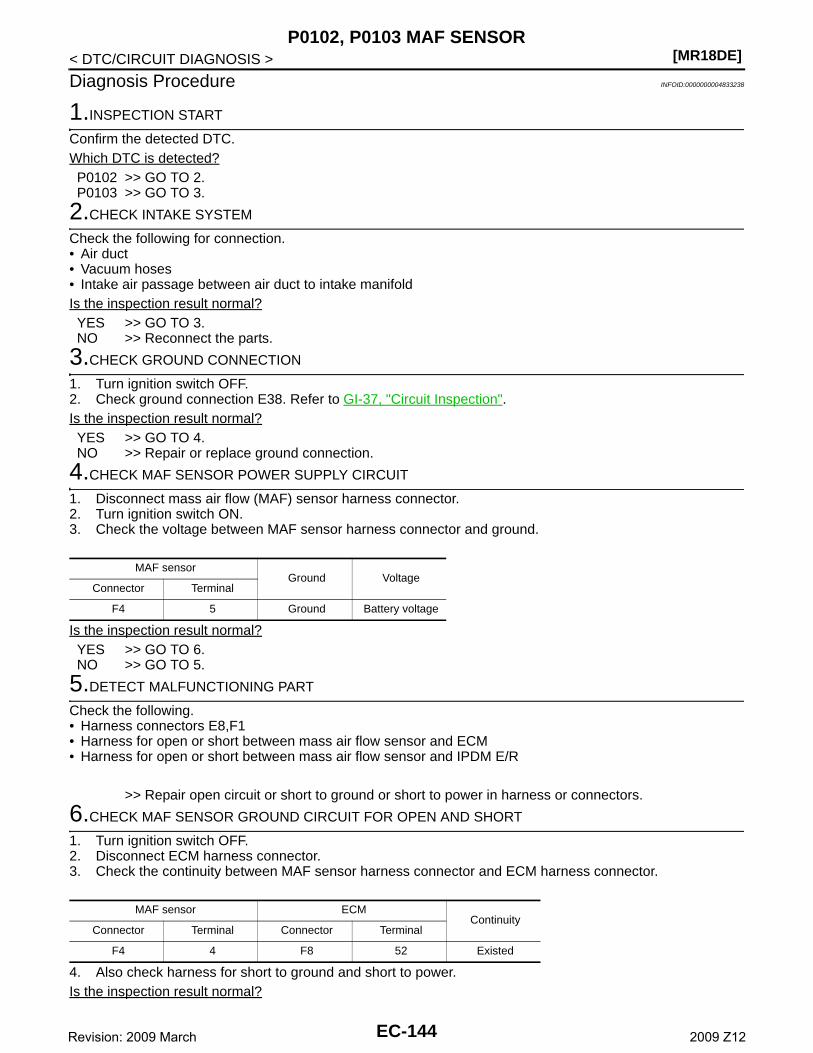
[MR18DE]P0102, P0103 MAF SENSOR
< DTC/CIRCUIT DIAGNOSIS >
Diagnosis Procedure INFOID:0000000004833238
1.INSPECTION START
Confirm the detected DTC.Which DTC is detected?P0102 >> GO TO 2.P0103 >> GO TO 3.
2.CHECK INTAKE SYSTEM
Check the following for connection.• Air duct• Vacuum hoses• Intake air passage between air duct to intake manifoldIs the inspection result normal?YES >> GO TO 3.NO >> Reconnect the parts.
3.CHECK GROUND CONNECTION
1. Turn ignition switch OFF.2. Check ground connection E38. Refer to GI-37, "Circuit Inspection". Is the inspection result normal?YES >> GO TO 4.NO >> Repair or replace ground connection.
4.CHECK MAF SENSOR POWER SUPPLY CIRCUIT
1. Disconnect mass air flow (MAF) sensor harness connector.2. Turn ignition switch ON.3. Check the voltage between MAF sensor harness connector and ground.
Is the inspection result normal?YES >> GO TO 6.NO >> GO TO 5.
5.DETECT MALFUNCTIONING PART
Check the following.• Harness connectors E8,F1• Harness for open or short between mass air flow sensor and ECM• Harness for open or short between mass air flow sensor and IPDM E/R
>> Repair open circuit or short to ground or short to power in harness or connectors.
6.CHECK MAF SENSOR GROUND CIRCUIT FOR OPEN AND SHORT
1. Turn ignition switch OFF.2. Disconnect ECM harness connector.3. Check the continuity between MAF sensor harness connector and ECM harness connector.
4. Also check harness for short to ground and short to power.Is the inspection result normal?
MAF sensorGround Voltage
Connector Terminal
F4 5 Ground Battery voltage
MAF sensor ECMContinuity
Connector Terminal Connector Terminal
F4 4 F8 52 Existed
EC-144Revision: 2009 March 2009 Z12
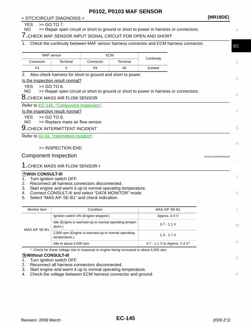
P0102, P0103 MAF SENSOR[MR18DE]
C
D
E
F
G
H
I
J
K
L
M
A
C
N
P
O
< DTC/CIRCUIT DIAGNOSIS >
E
YES >> GO TO 7.NO >> Repair open circuit or short to ground or short to power in harness or connectors.
7.CHECK MAF SENSOR INPUT SIGNAL CIRCUIT FOR OPEN AND SHORT
1. Check the continuity between MAF sensor harness connector and ECM harness connector.
2. Also check harness for short to ground and short to power.Is the inspection result normal?YES >> GO TO 8.NO >> Repair open circuit or short to ground or short to power in harness or connectors.
8.CHECK MASS AIR FLOW SENSOR
Refer to EC-145, "Component Inspection".Is the inspection result normal?YES >> GO TO 9.NO >> Replace mass air flow sensor.
9.CHECK INTERMITTENT INCIDENT
Refer to GI-34, "Intermittent Incident".
>> INSPECTION END
Component Inspection INFOID:0000000004833239
1.CHECK MASS AIR FLOW SENSOR-I
With CONSULT-III1. Turn ignition switch OFF.2. Reconnect all harness connectors disconnected.3. Start engine and warm it up to normal operating temperature.4. Connect CONSULT-III and select “DATA MONITOR” mode.5. Select “MAS A/F SE-B1” and check indication.
*: Check for linear voltage rise in response to engine being increased to about 4,000 rpm.
Without CONSULT-III1. Turn ignition switch OFF.2. Reconnect all harness connectors disconnected.3. Start engine and warm it up to normal operating temperature.4. Check the voltage between ECM harness connector and ground.
MAF sensor ECMContinuity
Connector Terminal Connector Terminal
F4 3 F8 45 Existed
Monitor item Condition MAS A/F SE-B1
MAS A/F SE-B1
Ignition switch ON (Engine stopped.) Approx. 0.4 V
Idle (Engine is warmed-up to normal operating temper-ature.)
0.7 - 1.1 V
2,500 rpm (Engine is warmed-up to normal operating temperature.)
1.3 - 1.7 V
Idle to about 4,000 rpm 0.7 - 1.1 V to Approx. 2.4 V*
EC-145Revision: 2009 March 2009 Z12
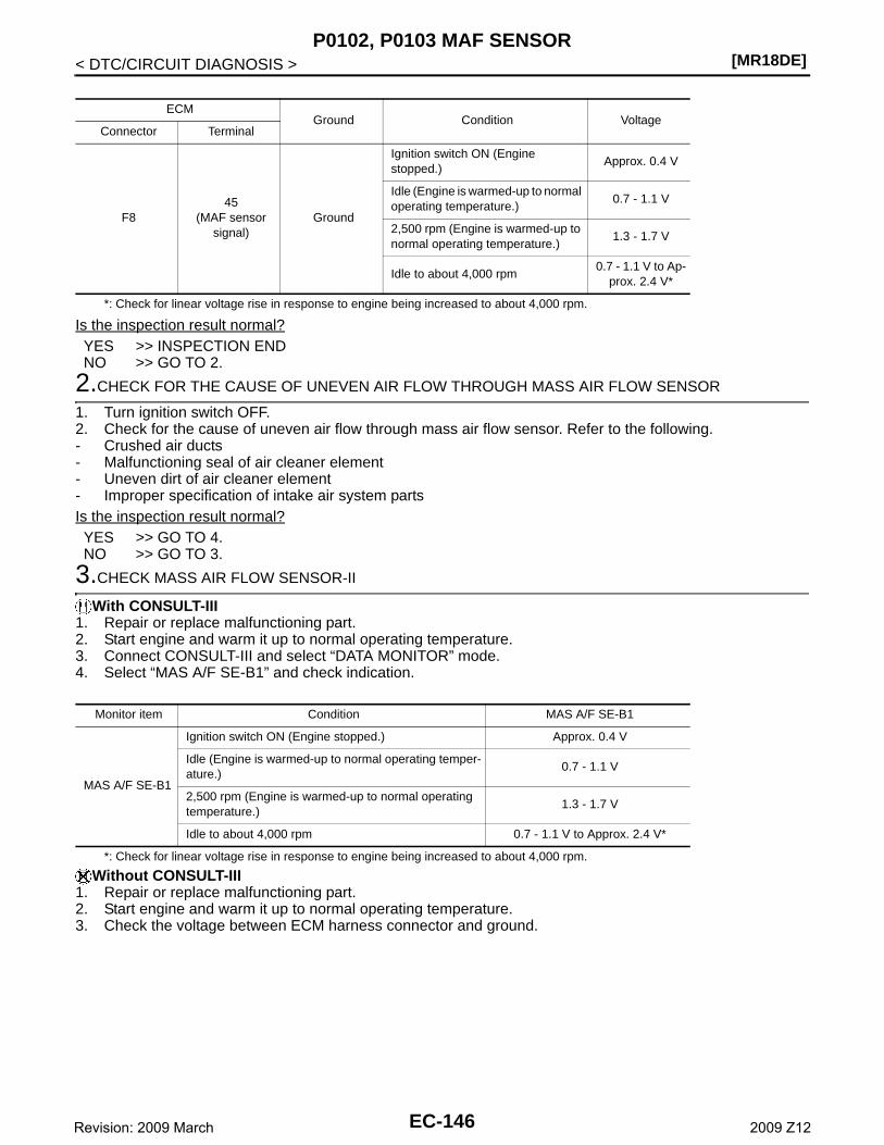
[MR18DE]P0102, P0103 MAF SENSOR
< DTC/CIRCUIT DIAGNOSIS >
*: Check for linear voltage rise in response to engine being increased to about 4,000 rpm.
Is the inspection result normal?YES >> INSPECTION ENDNO >> GO TO 2.
2.CHECK FOR THE CAUSE OF UNEVEN AIR FLOW THROUGH MASS AIR FLOW SENSOR
1. Turn ignition switch OFF.2. Check for the cause of uneven air flow through mass air flow sensor. Refer to the following.- Crushed air ducts- Malfunctioning seal of air cleaner element- Uneven dirt of air cleaner element- Improper specification of intake air system partsIs the inspection result normal?YES >> GO TO 4.NO >> GO TO 3.
3.CHECK MASS AIR FLOW SENSOR-II
With CONSULT-III1. Repair or replace malfunctioning part.2. Start engine and warm it up to normal operating temperature.3. Connect CONSULT-III and select “DATA MONITOR” mode.4. Select “MAS A/F SE-B1” and check indication.
*: Check for linear voltage rise in response to engine being increased to about 4,000 rpm.
Without CONSULT-III1. Repair or replace malfunctioning part.2. Start engine and warm it up to normal operating temperature.3. Check the voltage between ECM harness connector and ground.
ECMGround Condition Voltage
Connector Terminal
F845
(MAF sensor signal)
Ground
Ignition switch ON (Engine stopped.)
Approx. 0.4 V
Idle (Engine is warmed-up to normal operating temperature.)
0.7 - 1.1 V
2,500 rpm (Engine is warmed-up to normal operating temperature.)
1.3 - 1.7 V
Idle to about 4,000 rpm0.7 - 1.1 V to Ap-
prox. 2.4 V*
Monitor item Condition MAS A/F SE-B1
MAS A/F SE-B1
Ignition switch ON (Engine stopped.) Approx. 0.4 V
Idle (Engine is warmed-up to normal operating temper-ature.)
0.7 - 1.1 V
2,500 rpm (Engine is warmed-up to normal operating temperature.)
1.3 - 1.7 V
Idle to about 4,000 rpm 0.7 - 1.1 V to Approx. 2.4 V*
EC-146Revision: 2009 March 2009 Z12
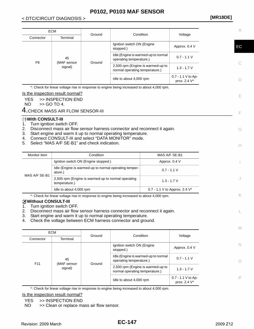
P0102, P0103 MAF SENSOR[MR18DE]
C
D
E
F
G
H
I
J
K
L
M
A
C
N
P
O
< DTC/CIRCUIT DIAGNOSIS >
E
*: Check for linear voltage rise in response to engine being increased to about 4,000 rpm.
Is the inspection result normal?YES >> INSPECTION ENDNO >> GO TO 4.
4.CHECK MASS AIR FLOW SENSOR-III
With CONSULT-III1. Turn ignition switch OFF.2. Disconnect mass air flow sensor harness connector and reconnect it again.3. Start engine and warm it up to normal operating temperature.4. Connect CONSULT-III and select “DATA MONITOR” mode.5. Select “MAS A/F SE-B1” and check indication.
*: Check for linear voltage rise in response to engine being increased to about 4,000 rpm.
Without CONSULT-III1. Turn ignition switch OFF.2. Disconnect mass air flow sensor harness connector and reconnect it again.3. Start engine and warm it up to normal operating temperature.4. Check the voltage between ECM harness connector and ground.
*: Check for linear voltage rise in response to engine being increased to about 4,000 rpm.
Is the inspection result normal?YES >> INSPECTION ENDNO >> Clean or replace mass air flow sensor.
ECMGround Condition Voltage
Connector Terminal
F845
(MAF sensor signal)
Ground
Ignition switch ON (Engine stopped.)
Approx. 0.4 V
Idle (Engine is warmed-up to normal operating temperature.)
0.7 - 1.1 V
2,500 rpm (Engine is warmed-up to normal operating temperature.)
1.3 - 1.7 V
Idle to about 4,000 rpm0.7 - 1.1 V to Ap-
prox. 2.4 V*
Monitor item Condition MAS A/F SE-B1
MAS A/F SE-B1
Ignition switch ON (Engine stopped.) Approx. 0.4 V
Idle (Engine is warmed-up to normal operating temper-ature.)
0.7 - 1.1 V
2,500 rpm (Engine is warmed-up to normal operating temperature.)
1.3 - 1.7 V
Idle to about 4,000 rpm 0.7 - 1.1 V to Approx. 2.4 V*
ECMGround Condition Voltage
Connector Terminal
F1145
(MAF sensor signal)
Ground
Ignition switch ON (Engine stopped.)
Approx. 0.4 V
Idle (Engine is warmed-up to normal operating temperature.)
0.7 - 1.1 V
2,500 rpm (Engine is warmed-up to normal operating temperature.)
1.3 - 1.7 V
Idle to about 4,000 rpm0.7 - 1.1 V to Ap-
prox. 2.4 V*
EC-147Revision: 2009 March 2009 Z12
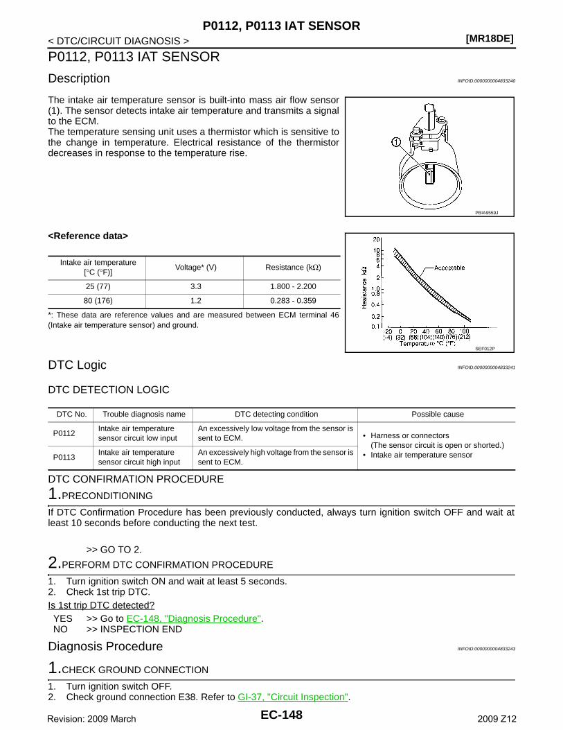
[MR18DE]P0112, P0113 IAT SENSOR
< DTC/CIRCUIT DIAGNOSIS >
P0112, P0113 IAT SENSOR
Description INFOID:0000000004833240
The intake air temperature sensor is built-into mass air flow sensor(1). The sensor detects intake air temperature and transmits a signalto the ECM.The temperature sensing unit uses a thermistor which is sensitive tothe change in temperature. Electrical resistance of the thermistordecreases in response to the temperature rise.
<Reference data>
*: These data are reference values and are measured between ECM terminal 46(Intake air temperature sensor) and ground.
DTC Logic INFOID:0000000004833241
DTC DETECTION LOGIC
DTC CONFIRMATION PROCEDURE
1.PRECONDITIONING
If DTC Confirmation Procedure has been previously conducted, always turn ignition switch OFF and wait atleast 10 seconds before conducting the next test.
>> GO TO 2.
2.PERFORM DTC CONFIRMATION PROCEDURE
1. Turn ignition switch ON and wait at least 5 seconds.2. Check 1st trip DTC.Is 1st trip DTC detected?YES >> Go to EC-148, "Diagnosis Procedure".NO >> INSPECTION END
Diagnosis Procedure INFOID:0000000004833243
1.CHECK GROUND CONNECTION
1. Turn ignition switch OFF.2. Check ground connection E38. Refer to GI-37, "Circuit Inspection".
PBIA9559J
Intake air temperature[°C (°F)]
Voltage* (V) Resistance (kΩ)
25 (77) 3.3 1.800 - 2.200
80 (176) 1.2 0.283 - 0.359
SEF012P
DTC No. Trouble diagnosis name DTC detecting condition Possible cause
P0112Intake air temperature sensor circuit low input
An excessively low voltage from the sensor is sent to ECM. • Harness or connectors
(The sensor circuit is open or shorted.)• Intake air temperature sensorP0113
Intake air temperature sensor circuit high input
An excessively high voltage from the sensor is sent to ECM.
EC-148Revision: 2009 March 2009 Z12
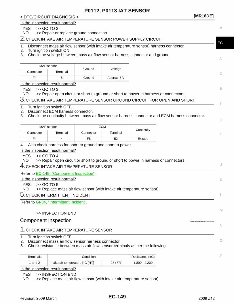
P0112, P0113 IAT SENSOR[MR18DE]
C
D
E
F
G
H
I
J
K
L
M
A
C
N
P
O
< DTC/CIRCUIT DIAGNOSIS >
E
Is the inspection result normal?YES >> GO TO 2.NO >> Repair or replace ground connection.
2.CHECK INTAKE AIR TEMPERATURE SENSOR POWER SUPPLY CIRCUIT
1. Disconnect mass air flow sensor (with intake air temperature sensor) harness connector.2. Turn ignition switch ON.3. Check the voltage between mass air flow sensor harness connector and ground.
Is the inspection result normal?YES >> GO TO 3.NO >> Repair open circuit or short to ground or short to power in harness or connectors.
3.CHECK INTAKE AIR TEMPERATURE SENSOR GROUND CIRCUIT FOR OPEN AND SHORT
1. Turn ignition switch OFF.2. Disconnect ECM harness connector.3. Check the continuity between mass air flow sensor harness connector and ECM harness connector.
4. Also check harness for short to ground and short to power.Is the inspection result normal?YES >> GO TO 4.NO >> Repair open circuit or short to ground or short to power in harness or connectors.
4.CHECK INTAKE AIR TEMPERATURE SENSOR
Refer to EC-149, "Component Inspection".Is the inspection result normal?YES >> GO TO 5.NO >> Replace mass air flow sensor (with intake air temperature sensor).
5.CHECK INTERMITTENT INCIDENT
Refer to GI-34, "Intermittent Incident".
>> INSPECTION END
Component Inspection INFOID:0000000004833244
1.CHECK INTAKE AIR TEMPERATURE SENSOR
1. Turn ignition switch OFF.2. Disconnect mass air flow sensor harness connector.3. Check resistance between mass air flow sensor terminals as per the following.
Is the inspection result normal?YES >> INSPECTION ENDNO >> Replace mass air flow sensor (with intake air temperature sensor).
MAF sensorGround Voltage
Connector Terminal
F4 5 Ground Approx. 5 V
MAF sensor ECMContinuity
Connector Terminal Connector Terminal
F4 4 F8 52 Existed
Terminals Condition Resistance (kΩ)
1 and 2 Intake air temperature [°C (°F)] 25 (77) 1.800 - 2.200
EC-149Revision: 2009 March 2009 Z12
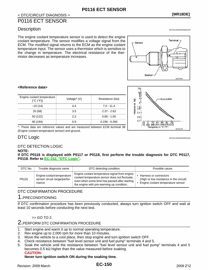
[MR18DE]P0116 ECT SENSOR
< DTC/CIRCUIT DIAGNOSIS >
P0116 ECT SENSOR
Description INFOID:0000000004833245
The engine coolant temperature sensor is used to detect the enginecoolant temperature. The sensor modifies a voltage signal from theECM. The modified signal returns to the ECM as the engine coolanttemperature input. The sensor uses a thermistor which is sensitive tothe change in temperature. The electrical resistance of the ther-mistor decreases as temperature increases.
<Reference data>
*: These data are reference values and are measured between ECM terminal 38(Engine coolant temperature sensor) and ground.
DTC Logic INFOID:0000000004833246
DTC DETECTION LOGICNOTE:If DTC P0116 is displayed with P0117 or P0118, first perform the trouble diagnosis for DTC P0117,P0118. Refer to EC-152, "DTC Logic".
DTC CONFIRMATION PROCEDURE
1.PRECONDITIONING
If DTC confirmation procedure has been previously conducted, always turn ignition switch OFF and wait atleast 10 seconds before conducting the next test.
>> GO TO 2.
2.PERFORM DTC CONFIRMATION PROCEDURE
1. Start engine and warm it up to normal operating temperature.2. Rev engine up to 2,000 rpm for more than 10 minutes.3. Move the vehicle to a cool place, then stop engine and turn ignition switch OFF.4. Check resistance between “fuel level sensor unit and fuel pump” terminals 4 and 5.5. Soak the vehicle until the resistance between “fuel level sensor unit and fuel pump” terminals 4 and 5
becomes 0.5 kΩ higher than the value measured before soaking.CAUTION:Never turn ignition switch ON during the soaking time.
SEF594K
Engine coolant temperature[°C (°F)]
Voltage* (V) Resistance (kΩ)
–10 (14) 4.4 7.0 - 11.4
20 (68) 3.5 2.37 - 2.63
50 (122) 2.2 0.68 - 1.00
90 (194) 0.9 0.236 - 0.260
SEF012P
DTC No. Trouble diagnosis name DTC detecting condition Possible cause
P0116Engine coolant temperature sensor circuit range/perfor-mance
Engine coolant temperature signal from engine coolant temperature sensor does not fluctuate, even when some time has passed after starting the engine with pre-warming up condition.
• Harness or connectors(High or low resistance in the circuit)
• Engine coolant temperature sensor
EC-150Revision: 2009 March 2009 Z12
P0116 ECT SENSOR[MR18DE]
C
D
E
F
G
H
I
J
K
L
M
A
C
N
P
O
< DTC/CIRCUIT DIAGNOSIS >
E
NOTE:Soak time changes depending on ambient air temperature. It may take several hours.
6. Start engine and let it idle for 5 minutes.7. Check 1st trip DTC.Is 1st trip DTC detected?YES >> EC-151, "Diagnosis Procedure".NO >> INSPECTION END
Diagnosis Procedure INFOID:0000000004833247
1.CHECK GROUND CONNECTION
1. Turn ignition switch OFF.2. Check ground connection E38. Refer to GI-37, "Circuit Inspection".Is the inspection result normal?YES >> GO TO 2.NO >> Repair or replace ground connection.
2.CHECK ENGINE COOLANT TEMPERATURE SENSOR
Refer to EC-151, "Component Inspection".Is the inspection result normal?YES >> GO TO 3.NO >> Replace engine coolant temperature sensor.
3.CHECK INTERMITTENT INCIDENT
Refer to GI-34, "Intermittent Incident".
>> INSPECTION END
Component Inspection INFOID:0000000004833248
1.CHECK ENGINE COOLANT TEMPERATURE SENSOR
1. Turn ignition switch OFF.2. Disconnect engine coolant temperature sensor harness connector.3. Remove engine coolant temperature sensor.4. Check resistance between engine coolant temperature sensor terminals by heating with hot water as
shown in the figure.
Is the inspection result normal?YES >> INSPECTION ENDNO >> Replace engine coolant temperature sensor.
Terminals Condition Resistance
1 and 2 Temperature [°C (°F)]
20 (68) 2.37 - 2.63 kΩ
50 (122) 0.68 - 1.00 kΩ
90 (194) 0.236 - 0.260 kΩ
EC-151Revision: 2009 March 2009 Z12
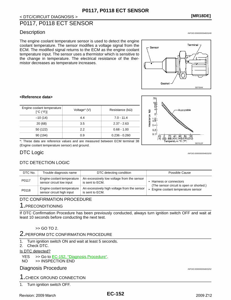
[MR18DE]P0117, P0118 ECT SENSOR
< DTC/CIRCUIT DIAGNOSIS >
P0117, P0118 ECT SENSOR
Description INFOID:0000000004833249
The engine coolant temperature sensor is used to detect the enginecoolant temperature. The sensor modifies a voltage signal from theECM. The modified signal returns to the ECM as the engine coolanttemperature input. The sensor uses a thermistor which is sensitive tothe change in temperature. The electrical resistance of the ther-mistor decreases as temperature increases.
<Reference data>
*: These data are reference values and are measured between ECM terminal 38(Engine coolant temperature sensor) and ground.
DTC Logic INFOID:0000000004833250
DTC DETECTION LOGIC
DTC CONFIRMATION PROCEDURE
1.PRECONDITIONING
If DTC Confirmation Procedure has been previously conducted, always turn ignition switch OFF and wait atleast 10 seconds before conducting the next test.
>> GO TO 2.
2.PERFORM DTC CONFIRMATION PROCEDURE
1. Turn ignition switch ON and wait at least 5 seconds.2. Check DTC.Is DTC detected?YES >> Go to EC-152, "Diagnosis Procedure".NO >> INSPECTION END
Diagnosis Procedure INFOID:0000000004833252
1.CHECK GROUND CONNECTION
1. Turn ignition switch OFF.
SEF594K
Engine coolant temperature[°C (°F)]
Voltage* (V) Resistance (kΩ)
–10 (14) 4.4 7.0 - 11.4
20 (68) 3.5 2.37 - 2.63
50 (122) 2.2 0.68 - 1.00
90 (194) 0.9 0.236 - 0.260
SEF012P
DTC No. Trouble diagnosis name DTC detecting condition Possible Cause
P0117Engine coolant temperature sensor circuit low input
An excessively low voltage from the sensor is sent to ECM. • Harness or connectors
(The sensor circuit is open or shorted.)• Engine coolant temperature sensor P0118
Engine coolant temperature sensor circuit high input
An excessively high voltage from the sensor is sent to ECM.
EC-152Revision: 2009 March 2009 Z12
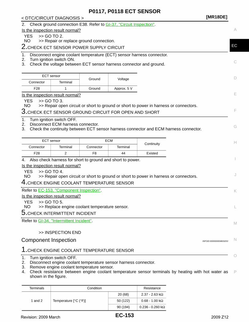
P0117, P0118 ECT SENSOR[MR18DE]
C
D
E
F
G
H
I
J
K
L
M
A
C
N
P
O
< DTC/CIRCUIT DIAGNOSIS >
E
2. Check ground connection E38. Refer to GI-37, "Circuit Inspection".Is the inspection result normal?YES >> GO TO 2.NO >> Repair or replace ground connection.
2.CHECK ECT SENSOR POWER SUPPLY CIRCUIT
1. Disconnect engine coolant temperature (ECT) sensor harness connector.2. Turn ignition switch ON.3. Check the voltage between ECT sensor harness connector and ground.
Is the inspection result normal?YES >> GO TO 3.NO >> Repair open circuit or short to ground or short to power in harness or connectors.
3.CHECK ECT SENSOR GROUND CIRCUIT FOR OPEN AND SHORT
1. Turn ignition switch OFF.2. Disconnect ECM harness connector.3. Check the continuity between ECT sensor harness connector and ECM harness connector.
4. Also check harness for short to ground and short to power.Is the inspection result normal?YES >> GO TO 4.NO >> Repair open circuit or short to ground or short to power in harness or connectors.
4.CHECK ENGINE COOLANT TEMPERATURE SENSOR
Refer to EC-153, "Component Inspection".Is the inspection result normal?YES >> GO TO 5.NO >> Replace engine coolant temperature sensor.
5.CHECK INTERMITTENT INCIDENT
Refer to GI-34, "Intermittent Incident".
>> INSPECTION END
Component Inspection INFOID:0000000004833253
1.CHECK ENGINE COOLANT TEMPERATURE SENSOR
1. Turn ignition switch OFF.2. Disconnect engine coolant temperature sensor harness connector.3. Remove engine coolant temperature sensor.4. Check resistance between engine coolant temperature sensor terminals by heating with hot water as
shown in the figure.
ECT sensorGround Voltage
Connector Terminal
F28 1 Ground Approx. 5 V
ECT sensor ECMContinuity
Connector Terminal Connector Terminal
F28 2 F8 44 Existed
Terminals Condition Resistance
1 and 2 Temperature [°C (°F)]
20 (68) 2.37 - 2.63 kΩ
50 (122) 0.68 - 1.00 kΩ
90 (194) 0.236 - 0.260 kΩ
EC-153Revision: 2009 March 2009 Z12
[MR18DE]P0117, P0118 ECT SENSOR
< DTC/CIRCUIT DIAGNOSIS >Is the inspection result normal?YES >> INSPECTION ENDNO >> Replace engine coolant temperature sensor.
EC-154Revision: 2009 March 2009 Z12
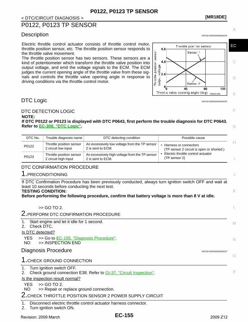
P0122, P0123 TP SENSOR[MR18DE]
C
D
E
F
G
H
I
J
K
L
M
A
C
N
P
O
< DTC/CIRCUIT DIAGNOSIS >
E
P0122, P0123 TP SENSOR
Description INFOID:0000000004833254
Electric throttle control actuator consists of throttle control motor,throttle position sensor, etc. The throttle position sensor responds tothe throttle valve movement. The throttle position sensor has two sensors. These sensors are akind of potentiometer which transform the throttle valve position intooutput voltage, and emit the voltage signals to the ECM. The ECMjudges the current opening angle of the throttle valve from these sig-nals and controls the throttle valve opening angle in response todriving conditions via the throttle control motor.
DTC Logic INFOID:0000000004833255
DTC DETECTION LOGICNOTE:If DTC P0122 or P0123 is displayed with DTC P0643, first perform the trouble diagnosis for DTC P0643.Refer to EC-308, "DTC Logic".
DTC CONFIRMATION PROCEDURE
1.PRECONDITIONING
If DTC Confirmation Procedure has been previously conducted, always turn ignition switch OFF and wait atleast 10 seconds before conducting the next test.TESTING CONDITION:Before performing the following procedure, confirm that battery voltage is more than 8 V at idle.
>> GO TO 2.
2.PERFORM DTC CONFIRMATION PROCEDURE
1. Start engine and let it idle for 1 second.2. Check DTC.Is DTC detected?YES >> Go to EC-155, "Diagnosis Procedure".NO >> INSPECTION END
Diagnosis Procedure INFOID:0000000004833257
1.CHECK GROUND CONNECTION
1. Turn ignition switch OFF.2. Check ground connection E38. Refer to GI-37, "Circuit Inspection".Is the inspection result normal?YES >> GO TO 2.NO >> Repair or replace ground connection.
2.CHECK THROTTLE POSITION SENSOR 2 POWER SUPPLY CIRCUIT
1. Disconnect electric throttle control actuator harness connector.2. Turn ignition switch ON.
PBIB0145E
DTC No. Trouble diagnosis name DTC detecting condition Possible cause
P0122Throttle position sensor 2 circuit low input
An excessively low voltage from the TP sensor 2 is sent to ECM.
• Harness or connectors(TP sensor 2 circuit is open or shorted.)
• Electric throttle control actuator(TP sensor 2)P0123
Throttle position sensor 2 circuit high input
An excessively high voltage from the TP sensor 2 is sent to ECM.
EC-155Revision: 2009 March 2009 Z12
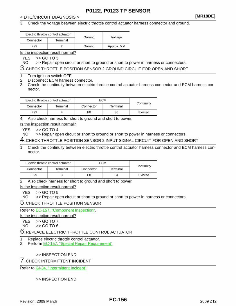
[MR18DE]P0122, P0123 TP SENSOR
< DTC/CIRCUIT DIAGNOSIS >3. Check the voltage between electric throttle control actuator harness connector and ground.
Is the inspection result normal?YES >> GO TO 3.NO >> Repair open circuit or short to ground or short to power in harness or connectors.
3.CHECK THROTTLE POSITION SENSOR 2 GROUND CIRCUIT FOR OPEN AND SHORT
1. Turn ignition switch OFF.2. Disconnect ECM harness connector.3. Check the continuity between electric throttle control actuator harness connector and ECM harness con-
nector.
4. Also check harness for short to ground and short to power.Is the inspection result normal?YES >> GO TO 4.NO >> Repair open circuit or short to ground or short to power in harness or connectors.
4.CHECK THROTTLE POSITION SENSOR 2 INPUT SIGNAL CIRCUIT FOR OPEN AND SHORT
1. Check the continuity between electric throttle control actuator harness connector and ECM harness con-nector.
2. Also check harness for short to ground and short to power.Is the inspection result normal?YES >> GO TO 5.NO >> Repair open circuit or short to ground or short to power in harness or connectors.
5.CHECK THROTTLE POSITION SENSOR
Refer to EC-157, "Component Inspection".Is the inspection result normal?YES >> GO TO 7.NO >> GO TO 6.
6.REPLACE ELECTRIC THROTTLE CONTROL ACTUATOR
1. Replace electric throttle control actuator.2. Perform EC-157, "Special Repair Requirement".
>> INSPECTION END
7.CHECK INTERMITTENT INCIDENT
Refer to GI-34, "Intermittent Incident".
>> INSPECTION END
Electric throttle control actuatorGround Voltage
Connector Terminal
F29 2 Ground Approx. 5 V
Electric throttle control actuator ECMContinuity
Connector Terminal Connector Terminal
F29 4 F8 36 Existed
Electric throttle control actuator ECMContinuity
Connector Terminal Connector Terminal
F29 3 F8 34 Existed
EC-156Revision: 2009 March 2009 Z12
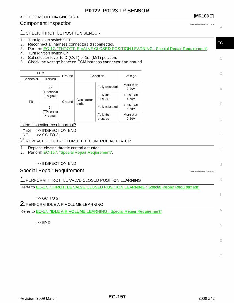
P0122, P0123 TP SENSOR[MR18DE]
C
D
E
F
G
H
I
J
K
L
M
A
C
N
P
O
< DTC/CIRCUIT DIAGNOSIS >
E
Component Inspection INFOID:0000000004833258
1.CHECK THROTTLE POSITION SENSOR
1. Turn ignition switch OFF.2. Reconnect all harness connectors disconnected.3. Perform EC-17, "THROTTLE VALVE CLOSED POSITION LEARNING : Special Repair Requirement".4. Turn ignition switch ON.5. Set selector lever to D (CVT) or 1st (M/T) position. 6. Check the voltage between ECM harness connector and ground.
Is the inspection result normal?YES >> INSPECTION ENDNO >> GO TO 2.
2.REPLACE ELECTRIC THROTTLE CONTROL ACTUATOR
1. Replace electric throttle control actuator.2. Perform EC-157, "Special Repair Requirement".
>> INSPECTION END
Special Repair Requirement INFOID:0000000004833259
1.PERFORM THROTTLE VALVE CLOSED POSITION LEARNING
Refer to EC-17, "THROTTLE VALVE CLOSED POSITION LEARNING : Special Repair Requirement"
>> GO TO 2.
2.PERFORM IDLE AIR VOLUME LEARNING
Refer to EC-17, "IDLE AIR VOLUME LEARNING : Special Repair Requirement"
>> END
ECMGround Condition Voltage
Connector Terminal
F8
33(TP sensor 1 signal)
GroundAccelerator pedal
Fully releasedMore than
0.36V
Fully de-pressed
Less than 4.75V
34 (TP sensor
2 signal)
Fully releasedLess than
4.75V
Fully de-pressed
More than 0.36V
EC-157Revision: 2009 March 2009 Z12
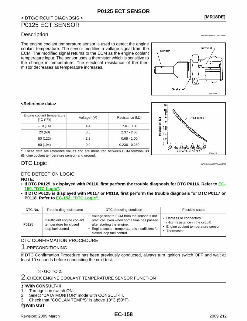
[MR18DE]P0125 ECT SENSOR
< DTC/CIRCUIT DIAGNOSIS >
P0125 ECT SENSOR
Description INFOID:0000000004833260
The engine coolant temperature sensor is used to detect the enginecoolant temperature. The sensor modifies a voltage signal from theECM. The modified signal returns to the ECM as the engine coolanttemperature input. The sensor uses a thermistor which is sensitive tothe change in temperature. The electrical resistance of the ther-mistor decreases as temperature increases.
<Reference data>
*: These data are reference values and are measured between ECM terminal 38(Engine coolant temperature sensor) and ground.
DTC Logic INFOID:0000000004833261
DTC DETECTION LOGICNOTE:• If DTC P0125 is displayed with P0116, first perform the trouble diagnosis for DTC P0116. Refer to EC-
150, "DTC Logic".• If DTC P0125 is displayed with P0117 or P0118, first perform the trouble diagnosis for DTC P0117 or
P0118. Refer to EC-152, "DTC Logic".
DTC CONFIRMATION PROCEDURE
1.PRECONDITIONING
If DTC Confirmation Procedure has been previously conducted, always turn ignition switch OFF and wait atleast 10 seconds before conducting the next test.
>> GO TO 2.
2.CHECK ENGINE COOLANT TEMPERATURE SENSOR FUNCTION
With CONSULT-III1. Turn ignition switch ON.2. Select “DATA MONITOR” mode with CONSULT-III.3. Check that “COOLAN TEMP/S” is above 10°C (50°F).
With GST
SEF594K
Engine coolant temperature[°C (°F)]
Voltage* (V) Resistance (kΩ)
–10 (14) 4.4 7.0 - 11.4
20 (68) 3.5 2.37 - 2.63
50 (122) 2.2 0.68 - 1.00
90 (194) 0.9 0.236 - 0.260
SEF012P
DTC No. Trouble diagnosis name DTC detecting condition Possible cause
P0125Insufficient engine coolant temperature for closed loop fuel control
• Voltage sent to ECM from the sensor is not practical, even when some time has passed after starting the engine.
• Engine coolant temperature is insufficient for closed loop fuel control.
• Harness or connectors(High resistance in the circuit)
• Engine coolant temperature sensor• Thermostat
EC-158Revision: 2009 March 2009 Z12
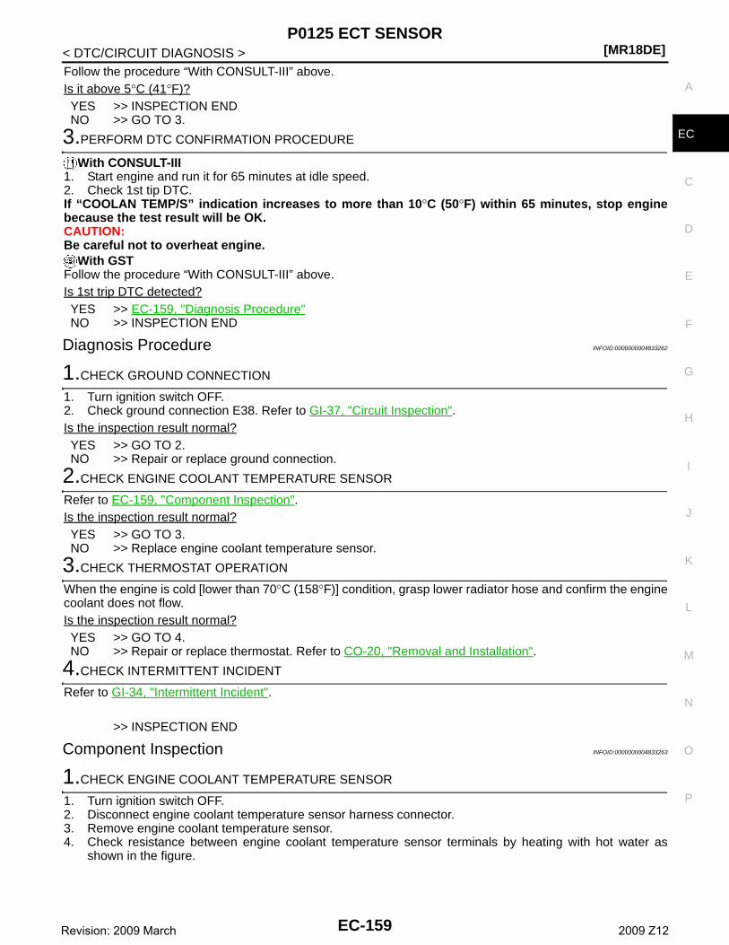
P0125 ECT SENSOR[MR18DE]
C
D
E
F
G
H
I
J
K
L
M
A
C
N
P
O
< DTC/CIRCUIT DIAGNOSIS >
E
Follow the procedure “With CONSULT-III” above.Is it above 5°C (41°F)?YES >> INSPECTION ENDNO >> GO TO 3.
3.PERFORM DTC CONFIRMATION PROCEDURE
With CONSULT-III1. Start engine and run it for 65 minutes at idle speed.2. Check 1st tip DTC.If “COOLAN TEMP/S” indication increases to more than 10°C (50°F) within 65 minutes, stop enginebecause the test result will be OK.CAUTION:Be careful not to overheat engine.
With GSTFollow the procedure “With CONSULT-III” above.Is 1st trip DTC detected?YES >> EC-159, "Diagnosis Procedure"NO >> INSPECTION END
Diagnosis Procedure INFOID:0000000004833262
1.CHECK GROUND CONNECTION
1. Turn ignition switch OFF.2. Check ground connection E38. Refer to GI-37, "Circuit Inspection".Is the inspection result normal?YES >> GO TO 2.NO >> Repair or replace ground connection.
2.CHECK ENGINE COOLANT TEMPERATURE SENSOR
Refer to EC-159, "Component Inspection".Is the inspection result normal?YES >> GO TO 3.NO >> Replace engine coolant temperature sensor.
3.CHECK THERMOSTAT OPERATION
When the engine is cold [lower than 70°C (158°F)] condition, grasp lower radiator hose and confirm the enginecoolant does not flow.Is the inspection result normal?YES >> GO TO 4.NO >> Repair or replace thermostat. Refer to CO-20, "Removal and Installation".
4.CHECK INTERMITTENT INCIDENT
Refer to GI-34, "Intermittent Incident".
>> INSPECTION END
Component Inspection INFOID:0000000004833263
1.CHECK ENGINE COOLANT TEMPERATURE SENSOR
1. Turn ignition switch OFF.2. Disconnect engine coolant temperature sensor harness connector.3. Remove engine coolant temperature sensor.4. Check resistance between engine coolant temperature sensor terminals by heating with hot water as
shown in the figure.
EC-159Revision: 2009 March 2009 Z12
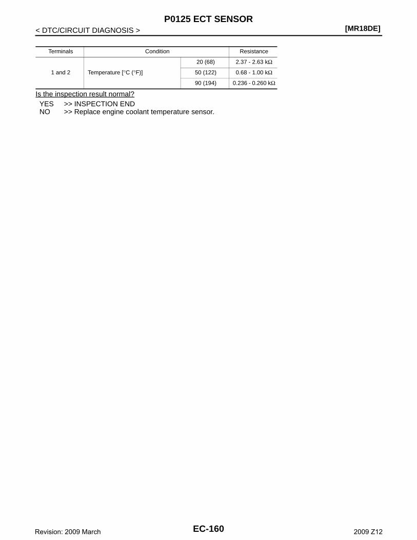
[MR18DE]P0125 ECT SENSOR
< DTC/CIRCUIT DIAGNOSIS >
Is the inspection result normal?YES >> INSPECTION ENDNO >> Replace engine coolant temperature sensor.
Terminals Condition Resistance
1 and 2 Temperature [°C (°F)]
20 (68) 2.37 - 2.63 kΩ
50 (122) 0.68 - 1.00 kΩ
90 (194) 0.236 - 0.260 kΩ
EC-160Revision: 2009 March 2009 Z12
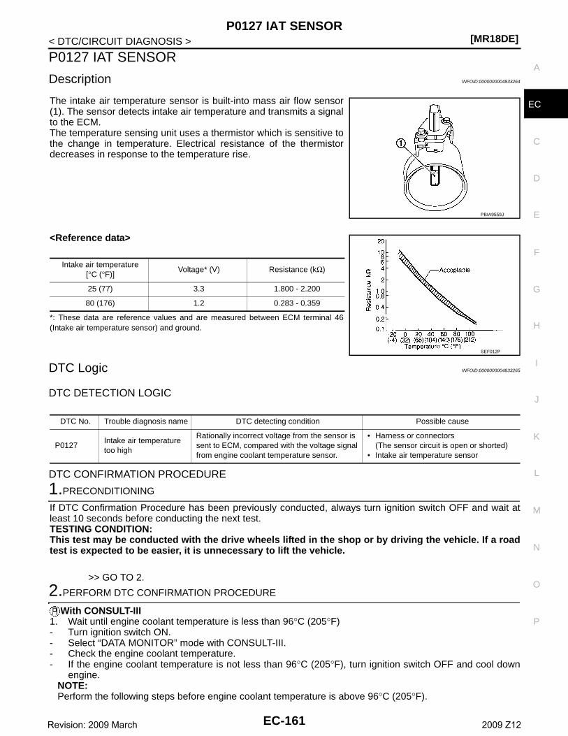
P0127 IAT SENSOR[MR18DE]
C
D
E
F
G
H
I
J
K
L
M
A
C
N
P
O
< DTC/CIRCUIT DIAGNOSIS >
E
P0127 IAT SENSOR
Description INFOID:0000000004833264
The intake air temperature sensor is built-into mass air flow sensor(1). The sensor detects intake air temperature and transmits a signalto the ECM.The temperature sensing unit uses a thermistor which is sensitive tothe change in temperature. Electrical resistance of the thermistordecreases in response to the temperature rise.
<Reference data>
*: These data are reference values and are measured between ECM terminal 46(Intake air temperature sensor) and ground.
DTC Logic INFOID:0000000004833265
DTC DETECTION LOGIC
DTC CONFIRMATION PROCEDURE
1.PRECONDITIONING
If DTC Confirmation Procedure has been previously conducted, always turn ignition switch OFF and wait atleast 10 seconds before conducting the next test.TESTING CONDITION:This test may be conducted with the drive wheels lifted in the shop or by driving the vehicle. If a roadtest is expected to be easier, it is unnecessary to lift the vehicle.
>> GO TO 2.
2.PERFORM DTC CONFIRMATION PROCEDURE
With CONSULT-III1. Wait until engine coolant temperature is less than 96°C (205°F)- Turn ignition switch ON.- Select “DATA MONITOR” mode with CONSULT-III.- Check the engine coolant temperature.- If the engine coolant temperature is not less than 96°C (205°F), turn ignition switch OFF and cool down
engine.NOTE:Perform the following steps before engine coolant temperature is above 96°C (205°F).
PBIA9559J
Intake air temperature[°C (°F)]
Voltage* (V) Resistance (kΩ)
25 (77) 3.3 1.800 - 2.200
80 (176) 1.2 0.283 - 0.359
SEF012P
DTC No. Trouble diagnosis name DTC detecting condition Possible cause
P0127Intake air temperature too high
Rationally incorrect voltage from the sensor is sent to ECM, compared with the voltage signal from engine coolant temperature sensor.
• Harness or connectors(The sensor circuit is open or shorted)
• Intake air temperature sensor
EC-161Revision: 2009 March 2009 Z12
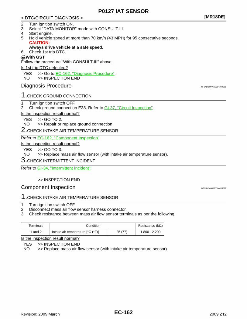
[MR18DE]P0127 IAT SENSOR
< DTC/CIRCUIT DIAGNOSIS >2. Turn ignition switch ON.3. Select “DATA MONITOR” mode with CONSULT-III.4. Start engine.5. Hold vehicle speed at more than 70 km/h (43 MPH) for 95 consecutive seconds.
CAUTION:Always drive vehicle at a safe speed.
6. Check 1st trip DTC.With GST
Follow the procedure “With CONSULT-III” above.Is 1st trip DTC detected?YES >> Go to EC-162, "Diagnosis Procedure".NO >> INSPECTION END
Diagnosis Procedure INFOID:0000000004833266
1.CHECK GROUND CONNECTION
1. Turn ignition switch OFF.2. Check ground connection E38. Refer to GI-37, "Circuit Inspection".Is the inspection result normal?YES >> GO TO 2.NO >> Repair or replace ground connection.
2.CHECK INTAKE AIR TEMPERATURE SENSOR
Refer to EC-162, "Component Inspection".Is the inspection result normal?YES >> GO TO 3.NO >> Replace mass air flow sensor (with intake air temperature sensor).
3.CHECK INTERMITTENT INCIDENT
Refer to GI-34, "Intermittent Incident".
>> INSPECTION END
Component Inspection INFOID:0000000004833267
1.CHECK INTAKE AIR TEMPERATURE SENSOR
1. Turn ignition switch OFF.2. Disconnect mass air flow sensor harness connector.3. Check resistance between mass air flow sensor terminals as per the following.
Is the inspection result normal?YES >> INSPECTION ENDNO >> Replace mass air flow sensor (with intake air temperature sensor).
Terminals Condition Resistance (kΩ)
1 and 2 Intake air temperature [°C (°F)] 25 (77) 1.800 - 2.200
EC-162Revision: 2009 March 2009 Z12
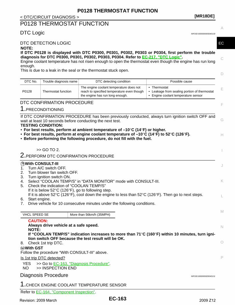
P0128 THERMOSTAT FUNCTION[MR18DE]
C
D
E
F
G
H
I
J
K
L
M
A
C
N
P
O
< DTC/CIRCUIT DIAGNOSIS >
E
P0128 THERMOSTAT FUNCTION
DTC Logic INFOID:0000000005040130
DTC DETECTION LOGICNOTE:If DTC P0128 is displayed with DTC P0300, P0301, P0302, P0303 or P0304, first perform the troublediagnosis for DTC P0300, P0301, P0302, P0303, P0304. Refer to EC-217, "DTC Logic".Engine coolant temperature has not risen enough to open the thermostat even though the engine has run longenough.This is due to a leak in the seal or the thermostat stuck open.
DTC CONFIRMATION PROCEDURE
1.PRECONDITIONING
If DTC CONFIRMATION PROCEDURE has been previously conducted, always turn ignition switch OFF andwait at least 10 seconds before conducting the next test.TESTING CONDITION:• For best results, perform at ambient temperature of –10°C (14°F) or higher.• For best results, perform at engine coolant temperature of –10°C (14°F) to 52°C (126°F).• Before performing the following procedure, do not fill with the fuel.
>> GO TO 2.
2.PERFORM DTC CONFIRMATION PROCEDURE
With CONSULT-III1. Turn A/C switch OFF.2. Turn blower fan switch OFF.3. Turn ignition switch ON.4. Select “COOLAN TEMP/S” in “DATA MONITOR” mode with CONSULT-III.5. Check the indication of “COOLAN TEMP/S”
If it is below 52°C (126°F), go to following step.If it is above 52°C (126°F), cool down the engine to less than 52°C (126°F). Then go to next steps.
6. Start engine.7. Drive vehicle for 10 consecutive minutes under the following conditions.
CAUTION:Always drive vehicle at a safe speed.NOTE:If “COOLAN TEMP/S” indication increases to more than 71°C (160°F) within 10 minutes, turn igni-tion switch OFF because the test result will be OK.
8. Check 1st trip DTC.With GST
Follow the procedure “With CONSULT-III” above.Is 1st trip DTC detected?YES >> Go to EC-163, "Diagnosis Procedure".NO >> INSPECTION END
Diagnosis Procedure INFOID:0000000005040131
1.CHECK ENGINE COOLANT TEMPERATURE SENSOR
Refer to EC-164, "Component Inspection".
DTC No. Trouble diagnosis name DTC detecting condition Possible cause
P0128 Thermostat functionThe engine coolant temperature does not reach to specified temperature even though the engine has run long enough.
• Thermostat• Leakage from sealing portion of thermostat• Engine coolant temperature sensor
VHCL SPEED SE More than 56km/h (35MPH)
EC-163Revision: 2009 March 2009 Z12
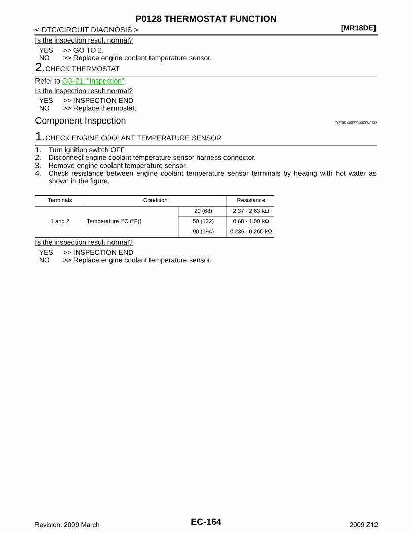
[MR18DE]P0128 THERMOSTAT FUNCTION
< DTC/CIRCUIT DIAGNOSIS >Is the inspection result normal?YES >> GO TO 2.NO >> Replace engine coolant temperature sensor.
2.CHECK THERMOSTAT
Refer to CO-21, "Inspection".Is the inspection result normal?YES >> INSPECTION ENDNO >> Replace thermostat.
Component Inspection INFOID:0000000005040132
1.CHECK ENGINE COOLANT TEMPERATURE SENSOR
1. Turn ignition switch OFF.2. Disconnect engine coolant temperature sensor harness connector.3. Remove engine coolant temperature sensor.4. Check resistance between engine coolant temperature sensor terminals by heating with hot water as
shown in the figure.
Is the inspection result normal?YES >> INSPECTION ENDNO >> Replace engine coolant temperature sensor.
Terminals Condition Resistance
1 and 2 Temperature [°C (°F)]
20 (68) 2.37 - 2.63 kΩ
50 (122) 0.68 - 1.00 kΩ
90 (194) 0.236 - 0.260 kΩ
EC-164Revision: 2009 March 2009 Z12
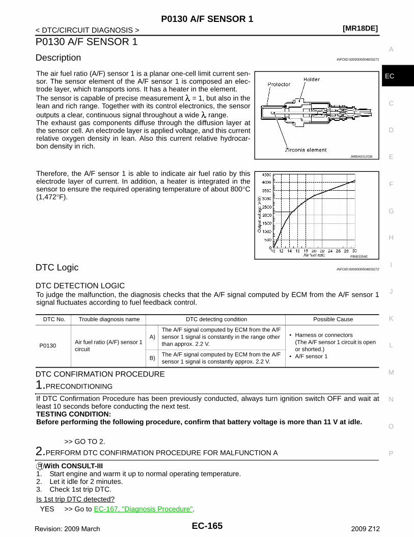
P0130 A/F SENSOR 1[MR18DE]
C
D
E
F
G
H
I
J
K
L
M
A
C
N
P
O
< DTC/CIRCUIT DIAGNOSIS >
E
P0130 A/F SENSOR 1
Description INFOID:0000000004833271
The air fuel ratio (A/F) sensor 1 is a planar one-cell limit current sen-sor. The sensor element of the A/F sensor 1 is composed an elec-trode layer, which transports ions. It has a heater in the element.The sensor is capable of precise measurement = 1, but also in thelean and rich range. Together with its control electronics, the sensoroutputs a clear, continuous signal throughout a wide range.The exhaust gas components diffuse through the diffusion layer atthe sensor cell. An electrode layer is applied voltage, and this currentrelative oxygen density in lean. Also this current relative hydrocar-bon density in rich.
Therefore, the A/F sensor 1 is able to indicate air fuel ratio by thiselectrode layer of current. In addition, a heater is integrated in thesensor to ensure the required operating temperature of about 800°C(1,472°F).
DTC Logic INFOID:0000000004833272
DTC DETECTION LOGICTo judge the malfunction, the diagnosis checks that the A/F signal computed by ECM from the A/F sensor 1signal fluctuates according to fuel feedback control.
DTC CONFIRMATION PROCEDURE
1.PRECONDITIONING
If DTC Confirmation Procedure has been previously conducted, always turn ignition switch OFF and wait atleast 10 seconds before conducting the next test.TESTING CONDITION:Before performing the following procedure, confirm that battery voltage is more than 11 V at idle.
>> GO TO 2.
2.PERFORM DTC CONFIRMATION PROCEDURE FOR MALFUNCTION A
With CONSULT-III1. Start engine and warm it up to normal operating temperature.2. Let it idle for 2 minutes.3. Check 1st trip DTC.Is 1st trip DTC detected?YES >> Go to EC-167, "Diagnosis Procedure".
JMBIA0112GB
PBIB3354E
DTC No. Trouble diagnosis name DTC detecting condition Possible Cause
P0130Air fuel ratio (A/F) sensor 1 circuit
A)The A/F signal computed by ECM from the A/F sensor 1 signal is constantly in the range other than approx. 2.2 V.
• Harness or connectors(The A/F sensor 1 circuit is open or shorted.)
• A/F sensor 1B)The A/F signal computed by ECM from the A/F sensor 1 signal is constantly approx. 2.2 V.
EC-165Revision: 2009 March 2009 Z12
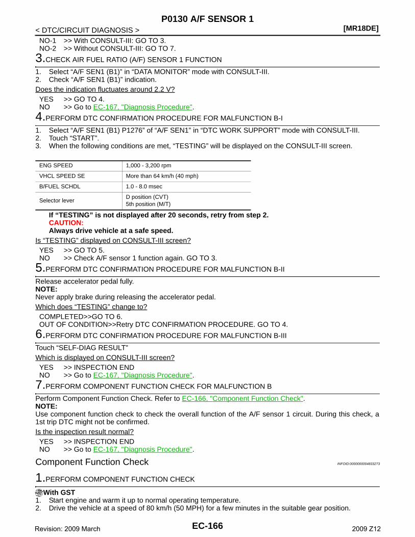
[MR18DE]P0130 A/F SENSOR 1
< DTC/CIRCUIT DIAGNOSIS >NO-1 >> With CONSULT-III: GO TO 3.NO-2 >> Without CONSULT-III: GO TO 7.
3.CHECK AIR FUEL RATIO (A/F) SENSOR 1 FUNCTION
1. Select “A/F SEN1 (B1)” in “DATA MONITOR” mode with CONSULT-III.2. Check “A/F SEN1 (B1)” indication.Does the indication fluctuates around 2.2 V?YES >> GO TO 4.NO >> Go to EC-167, "Diagnosis Procedure".
4.PERFORM DTC CONFIRMATION PROCEDURE FOR MALFUNCTION B-I
1. Select “A/F SEN1 (B1) P1276” of “A/F SEN1” in “DTC WORK SUPPORT” mode with CONSULT-III.2. Touch “START”.3. When the following conditions are met, “TESTING” will be displayed on the CONSULT-III screen.
If “TESTING” is not displayed after 20 seconds, retry from step 2.CAUTION:Always drive vehicle at a safe speed.
Is “TESTING” displayed on CONSULT-III screen?YES >> GO TO 5.NO >> Check A/F sensor 1 function again. GO TO 3.
5.PERFORM DTC CONFIRMATION PROCEDURE FOR MALFUNCTION B-II
Release accelerator pedal fully.NOTE:Never apply brake during releasing the accelerator pedal.Which does “TESTING” change to?COMPLETED>>GO TO 6.OUT OF CONDITION>>Retry DTC CONFIRMATION PROCEDURE. GO TO 4.
6.PERFORM DTC CONFIRMATION PROCEDURE FOR MALFUNCTION B-III
Touch “SELF-DIAG RESULT”Which is displayed on CONSULT-III screen?YES >> INSPECTION ENDNO >> Go to EC-167, "Diagnosis Procedure".
7.PERFORM COMPONENT FUNCTION CHECK FOR MALFUNCTION B
Perform Component Function Check. Refer to EC-166, "Component Function Check".NOTE:Use component function check to check the overall function of the A/F sensor 1 circuit. During this check, a1st trip DTC might not be confirmed.Is the inspection result normal?YES >> INSPECTION ENDNO >> Go to EC-167, "Diagnosis Procedure".
Component Function Check INFOID:0000000004833273
1.PERFORM COMPONENT FUNCTION CHECK
With GST1. Start engine and warm it up to normal operating temperature.2. Drive the vehicle at a speed of 80 km/h (50 MPH) for a few minutes in the suitable gear position.
ENG SPEED 1,000 - 3,200 rpm
VHCL SPEED SE More than 64 km/h (40 mph)
B/FUEL SCHDL 1.0 - 8.0 msec
Selector leverD position (CVT)5th position (M/T)
EC-166Revision: 2009 March 2009 Z12
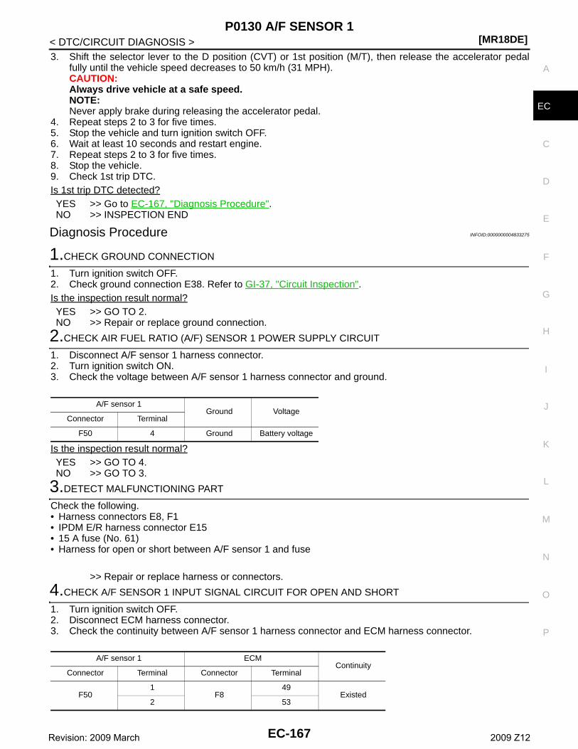
P0130 A/F SENSOR 1[MR18DE]
C
D
E
F
G
H
I
J
K
L
M
A
C
N
P
O
< DTC/CIRCUIT DIAGNOSIS >
E
3. Shift the selector lever to the D position (CVT) or 1st position (M/T), then release the accelerator pedalfully until the vehicle speed decreases to 50 km/h (31 MPH).CAUTION:Always drive vehicle at a safe speed.NOTE:Never apply brake during releasing the accelerator pedal.
4. Repeat steps 2 to 3 for five times.5. Stop the vehicle and turn ignition switch OFF.6. Wait at least 10 seconds and restart engine.7. Repeat steps 2 to 3 for five times.8. Stop the vehicle.9. Check 1st trip DTC.Is 1st trip DTC detected?YES >> Go to EC-167, "Diagnosis Procedure".NO >> INSPECTION END
Diagnosis Procedure INFOID:0000000004833275
1.CHECK GROUND CONNECTION
1. Turn ignition switch OFF.2. Check ground connection E38. Refer to GI-37, "Circuit Inspection".Is the inspection result normal?YES >> GO TO 2.NO >> Repair or replace ground connection.
2.CHECK AIR FUEL RATIO (A/F) SENSOR 1 POWER SUPPLY CIRCUIT
1. Disconnect A/F sensor 1 harness connector.2. Turn ignition switch ON.3. Check the voltage between A/F sensor 1 harness connector and ground.
Is the inspection result normal?YES >> GO TO 4.NO >> GO TO 3.
3.DETECT MALFUNCTIONING PART
Check the following.• Harness connectors E8, F1• IPDM E/R harness connector E15• 15 A fuse (No. 61)• Harness for open or short between A/F sensor 1 and fuse
>> Repair or replace harness or connectors.
4.CHECK A/F SENSOR 1 INPUT SIGNAL CIRCUIT FOR OPEN AND SHORT
1. Turn ignition switch OFF.2. Disconnect ECM harness connector.3. Check the continuity between A/F sensor 1 harness connector and ECM harness connector.
A/F sensor 1Ground Voltage
Connector Terminal
F50 4 Ground Battery voltage
A/F sensor 1 ECMContinuity
Connector Terminal Connector Terminal
F501
F849
Existed2 53
EC-167Revision: 2009 March 2009 Z12
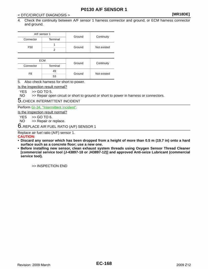
[MR18DE]P0130 A/F SENSOR 1
< DTC/CIRCUIT DIAGNOSIS >4. Check the continuity between A/F sensor 1 harness connector and ground, or ECM harness connector
and ground.
5. Also check harness for short to power.Is the inspection result normal?YES >> GO TO 5.NO >> Repair open circuit or short to ground or short to power in harness or connectors.
5.CHECK INTERMITTENT INCIDENT
Perform GI-34, "Intermittent Incident".Is the inspection result normal?YES >> GO TO 6.NO >> Repair or replace.
6.REPLACE AIR FUEL RATIO (A/F) SENSOR 1
Replace air fuel ratio (A/F) sensor 1.CAUTION:• Discard any sensor which has been dropped from a height of more than 0.5 m (19.7 in) onto a hard
surface such as a concrete floor; use a new one.• Before installing new sensor, clean exhaust system threads using Oxygen Sensor Thread Cleaner
[commercial service tool (J-43897-18 or J43897-12)] and approved Anti-seize Lubricant (commercialservice tool).
>> INSPECTION END
A/F sensor 1Ground Continuity
Connector Terminal
F501
Ground Not existed2
ECMGround Continuity
Connector Terminal
F849
Ground Not existed53
EC-168Revision: 2009 March 2009 Z12
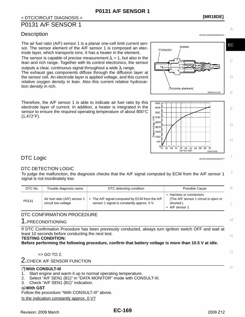
P0131 A/F SENSOR 1[MR18DE]
C
D
E
F
G
H
I
J
K
L
M
A
C
N
P
O
< DTC/CIRCUIT DIAGNOSIS >
E
P0131 A/F SENSOR 1
Description INFOID:0000000004833276
The air fuel ratio (A/F) sensor 1 is a planar one-cell limit current sen-sor. The sensor element of the A/F sensor 1 is composed an elec-trode layer, which transports ions. It has a heater in the element.The sensor is capable of precise measurement = 1, but also in thelean and rich range. Together with its control electronics, the sensoroutputs a clear, continuous signal throughout a wide range.The exhaust gas components diffuse through the diffusion layer atthe sensor cell. An electrode layer is applied voltage, and this currentrelative oxygen density in lean. Also this current relative hydrocar-bon density in rich.
Therefore, the A/F sensor 1 is able to indicate air fuel ratio by thiselectrode layer of current. In addition, a heater is integrated in thesensor to ensure the required operating temperature of about 800°C(1,472°F).
DTC Logic INFOID:0000000004833277
DTC DETECTION LOGICTo judge the malfunction, the diagnosis checks that the A/F signal computed by ECM from the A/F sensor 1signal is not inordinately low.
DTC CONFIRMATION PROCEDURE
1.PRECONDITIONING
If DTC Confirmation Procedure has been previously conducted, always turn ignition switch OFF and wait atleast 10 seconds before conducting the next test.TESTING CONDITION:Before performing the following procedure, confirm that battery voltage is more than 10.5 V at idle.
>> GO TO 2.
2.CHECK A/F SENSOR FUNCTION
With CONSULT-III1. Start engine and warm it up to normal operating temperature.2. Select “A/F SEN1 (B1)” in “DATA MONITOR” mode with CONSULT-III.3. Check “A/F SEN1 (B1)” indication.
With GSTFollow the procedure “With CONSULT-III” above.Is the indication constantly approx. 0 V?
JMBIA0112GB
PBIB3354E
DTC No. Trouble diagnosis name DTC detecting condition Possible Cause
P0131Air fuel ratio (A/F) sensor 1 circuit low voltage
• The A/F signal computed by ECM from the A/F sensor 1 signal is constantly approx. 0 V.
• Harness or connectors(The A/F sensor 1 circuit is open or shorted.)
• A/F sensor 1
EC-169Revision: 2009 March 2009 Z12
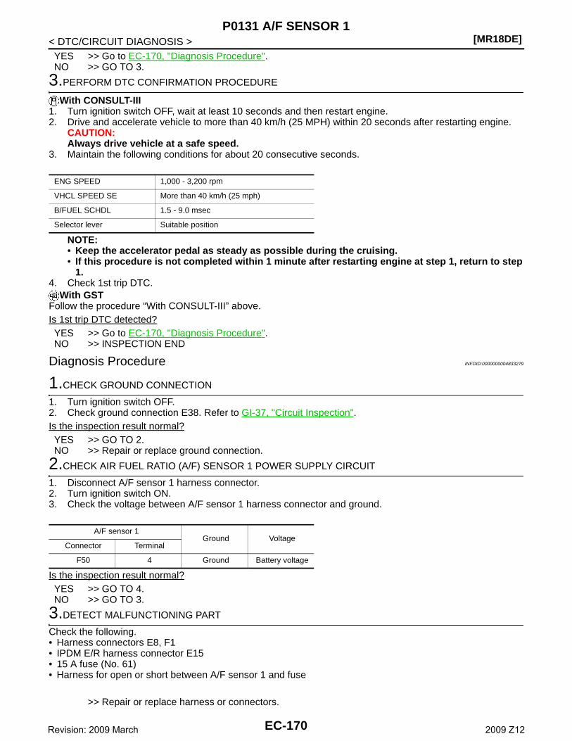
[MR18DE]P0131 A/F SENSOR 1
< DTC/CIRCUIT DIAGNOSIS >YES >> Go to EC-170, "Diagnosis Procedure".NO >> GO TO 3.
3.PERFORM DTC CONFIRMATION PROCEDURE
With CONSULT-III1. Turn ignition switch OFF, wait at least 10 seconds and then restart engine.2. Drive and accelerate vehicle to more than 40 km/h (25 MPH) within 20 seconds after restarting engine.
CAUTION:Always drive vehicle at a safe speed.
3. Maintain the following conditions for about 20 consecutive seconds.
NOTE:• Keep the accelerator pedal as steady as possible during the cruising.• If this procedure is not completed within 1 minute after restarting engine at step 1, return to step
1.4. Check 1st trip DTC.
With GSTFollow the procedure “With CONSULT-III” above.Is 1st trip DTC detected?YES >> Go to EC-170, "Diagnosis Procedure".NO >> INSPECTION END
Diagnosis Procedure INFOID:0000000004833279
1.CHECK GROUND CONNECTION
1. Turn ignition switch OFF.2. Check ground connection E38. Refer to GI-37, "Circuit Inspection".Is the inspection result normal?YES >> GO TO 2.NO >> Repair or replace ground connection.
2.CHECK AIR FUEL RATIO (A/F) SENSOR 1 POWER SUPPLY CIRCUIT
1. Disconnect A/F sensor 1 harness connector.2. Turn ignition switch ON.3. Check the voltage between A/F sensor 1 harness connector and ground.
Is the inspection result normal?YES >> GO TO 4.NO >> GO TO 3.
3.DETECT MALFUNCTIONING PART
Check the following.• Harness connectors E8, F1• IPDM E/R harness connector E15• 15 A fuse (No. 61)• Harness for open or short between A/F sensor 1 and fuse
>> Repair or replace harness or connectors.
ENG SPEED 1,000 - 3,200 rpm
VHCL SPEED SE More than 40 km/h (25 mph)
B/FUEL SCHDL 1.5 - 9.0 msec
Selector lever Suitable position
A/F sensor 1Ground Voltage
Connector Terminal
F50 4 Ground Battery voltage
EC-170Revision: 2009 March 2009 Z12
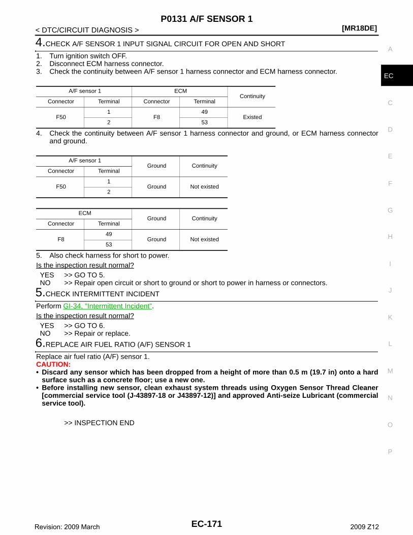
P0131 A/F SENSOR 1[MR18DE]
C
D
E
F
G
H
I
J
K
L
M
A
C
N
P
O
< DTC/CIRCUIT DIAGNOSIS >
E
4.CHECK A/F SENSOR 1 INPUT SIGNAL CIRCUIT FOR OPEN AND SHORT
1. Turn ignition switch OFF.2. Disconnect ECM harness connector.3. Check the continuity between A/F sensor 1 harness connector and ECM harness connector.
4. Check the continuity between A/F sensor 1 harness connector and ground, or ECM harness connectorand ground.
5. Also check harness for short to power.Is the inspection result normal?YES >> GO TO 5.NO >> Repair open circuit or short to ground or short to power in harness or connectors.
5.CHECK INTERMITTENT INCIDENT
Perform GI-34, "Intermittent Incident".Is the inspection result normal?YES >> GO TO 6.NO >> Repair or replace.
6.REPLACE AIR FUEL RATIO (A/F) SENSOR 1
Replace air fuel ratio (A/F) sensor 1.CAUTION:• Discard any sensor which has been dropped from a height of more than 0.5 m (19.7 in) onto a hard
surface such as a concrete floor; use a new one.• Before installing new sensor, clean exhaust system threads using Oxygen Sensor Thread Cleaner
[commercial service tool (J-43897-18 or J43897-12)] and approved Anti-seize Lubricant (commercialservice tool).
>> INSPECTION END
A/F sensor 1 ECMContinuity
Connector Terminal Connector Terminal
F501
F849
Existed2 53
A/F sensor 1Ground Continuity
Connector Terminal
F501
Ground Not existed2
ECMGround Continuity
Connector Terminal
F849
Ground Not existed53
EC-171Revision: 2009 March 2009 Z12
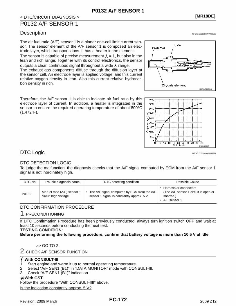
[MR18DE]P0132 A/F SENSOR 1
< DTC/CIRCUIT DIAGNOSIS >
P0132 A/F SENSOR 1
Description INFOID:0000000004833280
The air fuel ratio (A/F) sensor 1 is a planar one-cell limit current sen-sor. The sensor element of the A/F sensor 1 is composed an elec-trode layer, which transports ions. It has a heater in the element.The sensor is capable of precise measurement = 1, but also in thelean and rich range. Together with its control electronics, the sensoroutputs a clear, continuous signal throughout a wide range.The exhaust gas components diffuse through the diffusion layer atthe sensor cell. An electrode layer is applied voltage, and this currentrelative oxygen density in lean. Also this current relative hydrocar-bon density in rich.
Therefore, the A/F sensor 1 is able to indicate air fuel ratio by thiselectrode layer of current. In addition, a heater is integrated in thesensor to ensure the required operating temperature of about 800°C(1,472°F).
DTC Logic INFOID:0000000004833281
DTC DETECTION LOGICTo judge the malfunction, the diagnosis checks that the A/F signal computed by ECM from the A/F sensor 1signal is not inordinately high.
DTC CONFIRMATION PROCEDURE
1.PRECONDITIONING
If DTC Confirmation Procedure has been previously conducted, always turn ignition switch OFF and wait atleast 10 seconds before conducting the next test.TESTING CONDITION:Before performing the following procedure, confirm that battery voltage is more than 10.5 V at idle.
>> GO TO 2.
2.CHECK A/F SENSOR FUNCTION
With CONSULT-III1. Start engine and warm it up to normal operating temperature.2. Select “A/F SEN1 (B1)” in “DATA MONITOR” mode with CONSULT-III.3. Check “A/F SEN1 (B1)” indication.
With GSTFollow the procedure “With CONSULT-IIII” above.Is the indication constantly approx. 5 V?
JMBIA0112GB
PBIB3354E
DTC No. Trouble diagnosis name DTC detecting condition Possible Cause
P0132Air fuel ratio (A/F) sensor 1 circuit high voltage
• The A/F signal computed by ECM from the A/F sensor 1 signal is constantly approx. 5 V.
• Harness or connectors(The A/F sensor 1 circuit is open or shorted.)
• A/F sensor 1
EC-172Revision: 2009 March 2009 Z12
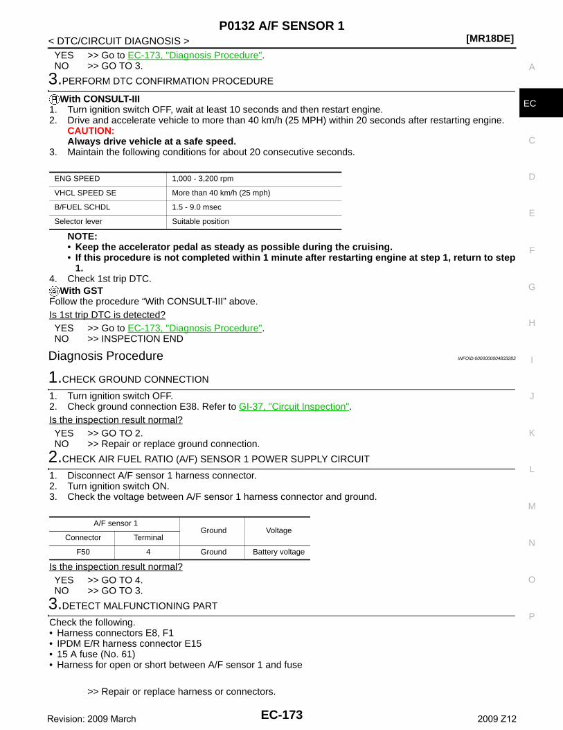
P0132 A/F SENSOR 1[MR18DE]
C
D
E
F
G
H
I
J
K
L
M
A
C
N
P
O
< DTC/CIRCUIT DIAGNOSIS >
E
YES >> Go to EC-173, "Diagnosis Procedure".NO >> GO TO 3.
3.PERFORM DTC CONFIRMATION PROCEDURE
With CONSULT-III1. Turn ignition switch OFF, wait at least 10 seconds and then restart engine.2. Drive and accelerate vehicle to more than 40 km/h (25 MPH) within 20 seconds after restarting engine.
CAUTION:Always drive vehicle at a safe speed.
3. Maintain the following conditions for about 20 consecutive seconds.
NOTE:• Keep the accelerator pedal as steady as possible during the cruising.• If this procedure is not completed within 1 minute after restarting engine at step 1, return to step
1.4. Check 1st trip DTC.
With GSTFollow the procedure “With CONSULT-III” above.Is 1st trip DTC is detected?YES >> Go to EC-173, "Diagnosis Procedure".NO >> INSPECTION END
Diagnosis Procedure INFOID:0000000004833283
1.CHECK GROUND CONNECTION
1. Turn ignition switch OFF.2. Check ground connection E38. Refer to GI-37, "Circuit Inspection".Is the inspection result normal?YES >> GO TO 2.NO >> Repair or replace ground connection.
2.CHECK AIR FUEL RATIO (A/F) SENSOR 1 POWER SUPPLY CIRCUIT
1. Disconnect A/F sensor 1 harness connector.2. Turn ignition switch ON.3. Check the voltage between A/F sensor 1 harness connector and ground.
Is the inspection result normal?YES >> GO TO 4.NO >> GO TO 3.
3.DETECT MALFUNCTIONING PART
Check the following.• Harness connectors E8, F1• IPDM E/R harness connector E15• 15 A fuse (No. 61)• Harness for open or short between A/F sensor 1 and fuse
>> Repair or replace harness or connectors.
ENG SPEED 1,000 - 3,200 rpm
VHCL SPEED SE More than 40 km/h (25 mph)
B/FUEL SCHDL 1.5 - 9.0 msec
Selector lever Suitable position
A/F sensor 1Ground Voltage
Connector Terminal
F50 4 Ground Battery voltage
EC-173Revision: 2009 March 2009 Z12
[MR18DE]P0132 A/F SENSOR 1
< DTC/CIRCUIT DIAGNOSIS >
4.CHECK A/F SENSOR 1 INPUT SIGNAL CIRCUIT FOR OPEN AND SHORT
1. Turn ignition switch OFF.2. Disconnect ECM harness connector.3. Check the continuity between A/F sensor 1 harness connector and ECM harness connector.
4. Check the continuity between A/F sensor 1 harness connector and ground, or ECM harness connectorand ground.
5. Also check harness for short to power.Is the inspection result normal?YES >> GO TO 5.NO >> Repair open circuit or short to ground or short to power in harness or connectors.
5.CHECK INTERMITTENT INCIDENT
Perform GI-34, "Intermittent Incident".Is the inspection result normal?YES >> GO TO 6.NO >> Repair or replace.
6.REPLACE AIR FUEL RATIO (A/F) SENSOR 1
Replace air fuel ratio (A/F) sensor 1.CAUTION:• Discard any sensor which has been dropped from a height of more than 0.5 m (19.7 in) onto a hard
surface such as a concrete floor; use a new one.• Before installing new sensor, clean exhaust system threads using Oxygen Sensor Thread Cleaner
[commercial service tool (J-43897-18 or J43897-12)] and approved Anti-seize Lubricant (commercialservice tool).
>> INSPECTION END
A/F sensor 1 ECMContinuity
Connector Terminal Connector Terminal
F501
F849
Existed2 53
A/F sensor 1Ground Continuity
Connector Terminal
F501
Ground Not existed2
ECMGround Continuity
Connector Terminal
F849
Ground Not existed53
EC-174Revision: 2009 March 2009 Z12
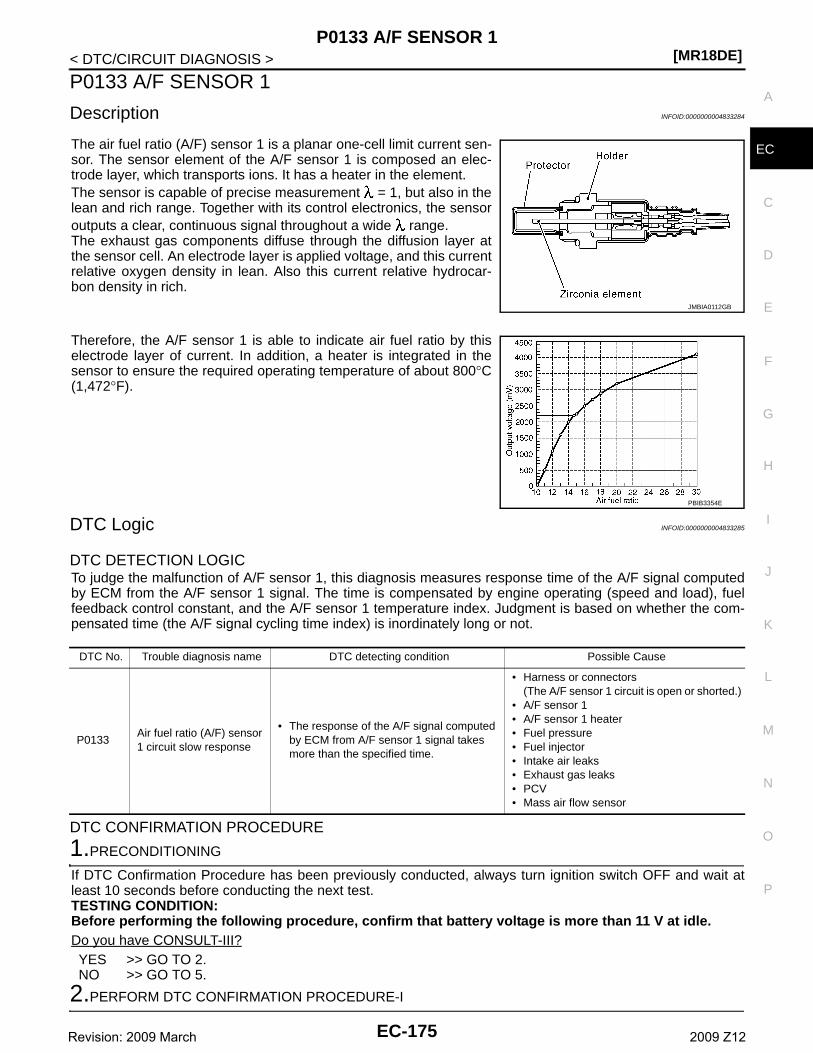
P0133 A/F SENSOR 1[MR18DE]
C
D
E
F
G
H
I
J
K
L
M
A
C
N
P
O
< DTC/CIRCUIT DIAGNOSIS >
E
P0133 A/F SENSOR 1
Description INFOID:0000000004833284
The air fuel ratio (A/F) sensor 1 is a planar one-cell limit current sen-sor. The sensor element of the A/F sensor 1 is composed an elec-trode layer, which transports ions. It has a heater in the element.The sensor is capable of precise measurement = 1, but also in thelean and rich range. Together with its control electronics, the sensoroutputs a clear, continuous signal throughout a wide range.The exhaust gas components diffuse through the diffusion layer atthe sensor cell. An electrode layer is applied voltage, and this currentrelative oxygen density in lean. Also this current relative hydrocar-bon density in rich.
Therefore, the A/F sensor 1 is able to indicate air fuel ratio by thiselectrode layer of current. In addition, a heater is integrated in thesensor to ensure the required operating temperature of about 800°C(1,472°F).
DTC Logic INFOID:0000000004833285
DTC DETECTION LOGICTo judge the malfunction of A/F sensor 1, this diagnosis measures response time of the A/F signal computedby ECM from the A/F sensor 1 signal. The time is compensated by engine operating (speed and load), fuelfeedback control constant, and the A/F sensor 1 temperature index. Judgment is based on whether the com-pensated time (the A/F signal cycling time index) is inordinately long or not.
DTC CONFIRMATION PROCEDURE
1.PRECONDITIONING
If DTC Confirmation Procedure has been previously conducted, always turn ignition switch OFF and wait atleast 10 seconds before conducting the next test.TESTING CONDITION:Before performing the following procedure, confirm that battery voltage is more than 11 V at idle.Do you have CONSULT-III?YES >> GO TO 2.NO >> GO TO 5.
2.PERFORM DTC CONFIRMATION PROCEDURE-I
JMBIA0112GB
PBIB3354E
DTC No. Trouble diagnosis name DTC detecting condition Possible Cause
P0133Air fuel ratio (A/F) sensor 1 circuit slow response
• The response of the A/F signal computed by ECM from A/F sensor 1 signal takes more than the specified time.
• Harness or connectors(The A/F sensor 1 circuit is open or shorted.)
• A/F sensor 1• A/F sensor 1 heater• Fuel pressure• Fuel injector• Intake air leaks• Exhaust gas leaks• PCV• Mass air flow sensor
EC-175Revision: 2009 March 2009 Z12
[MR18DE]P0133 A/F SENSOR 1
< DTC/CIRCUIT DIAGNOSIS >
With CONSULT-III1. Start engine and warm it up to normal operating temperature.2. Turn ignition switch OFF and wait at least 10 seconds.3. Start engine and keep the engine speed between 3,500 and 4,000 rpm for at least 1minute under no load.4. Let engine idle for 1 minute.5. Select “A/F SEN1(B1) P1278/P1279” of “A/F SEN1” in “DTC WORK SUPPORT” mode with CONSULT-III.6. Touch “START”.Is “COMPLETED” displayed on COUSULT-III?YES >> GO TO 3NO >> GO TO 4.
3.PERFORM DTC CONFIRMATION PROCEDURE-II
Touch “SELF-DIAG RESULT”.Which is displayed on CONSULT-III?OK >> INSPECTION ENDNG >> Go to EC-177, "Diagnosis Procedure".
4.PERFORM DTC CONFIRMATION PROCEDURE
1. After perform the following procedure, “TESTING” will be displayed on the CONSULT-III screen.- Increase the engine speed up to 4,000 to 5,000 rpm and keep it for 10 seconds.- Fully release accelerator pedal and then let engine idle for about 10 seconds.
If “TESTING” is not displayed after 10 seconds, go to EC-109, "Component Function Check".2. Wait for about 20 seconds at idle under the condition that “TESTING” is displayed on the CONSULT-III
screen.3. Make sure that “TESTING” changes to “COMPLETED”.
If “TESTING” changed to “OUT OF CONDITION”, go to EC-109, "Component Function Check". 4. Touch “SELF-DIAG RESULT”.Which is displayed on CONSULT-III?OK >> INSPECTION ENDNG >> Go to EC-177, "Diagnosis Procedure".
5.CHECK AIR-FUEL RATIO SELF-LEARNING VALUE
With GST1. Start engine and warm it up to normal operating temperature.2. Select Service $01 with GST.3. Calculate the total value of “Short-term fuel trim” and “Long-term fuel trim” indications.Is the total percentage within ±15%?YES >> GO TO 7.NO >> GO TO 6.
6.DETECT MALFUNCTIONING PART
Check the following.• Intake air leaks• Exhaust gas leaks• Incorrect fuel pressure• Lack of fuel• Fuel injector• Incorrect PCV hose connection• PCV valve• Mass air flow sensor
>> Repair or replace malfunctioning part.
7.PERFORM DTC CONFIRMATION PROCEDURE
1. Turn ignition switch OFF and wait at least 10 seconds.2. Start engine and keep the engine speed between 3,500 and 4,000 rpm for at least 1minute under no load.3. Let engine idle for 1 minute.4. Increase the engine speed up to 4,000 to 5,000 rpm and keep it for 10 seconds.
EC-176Revision: 2009 March 2009 Z12
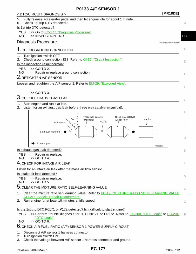
P0133 A/F SENSOR 1[MR18DE]
C
D
E
F
G
H
I
J
K
L
M
A
C
N
P
O
< DTC/CIRCUIT DIAGNOSIS >
E
5. Fully release accelerator pedal and then let engine idle for about 1 minute.6. Check 1st trip DTC detected?.Is 1st trip DTC detected?YES >> Go to EC-177, "Diagnosis Procedure".NO >> INSPECTION END
Diagnosis Procedure INFOID:0000000004833287
1.CHECK GROUND CONNECTION
1. Turn ignition switch OFF.2. Check ground connection E38. Refer to GI-37, "Circuit Inspection".Is the inspection result normal?YES >> GO TO 2.NO >> Repair or replace ground connection.
2.RETIGHTEN A/F SENSOR 1
Loosen and retighten the A/F sensor 1. Refer to EM-29, "Exploded View".
>> GO TO 3.
3.CHECK EXHAUST GAS LEAK
1. Start engine and run it at idle.2. Listen for an exhaust gas leak before three way catalyst (manifold).
Is exhaust gas leak detected?YES >> Repair or replace.NO >> GO TO 4.
4.CHECK FOR INTAKE AIR LEAK
Listen for an intake air leak after the mass air flow sensor.Is intake air leak detected?YES >> Repair or replace.NO >> GO TO 5.
5.CLEAR THE MIXTURE RATIO SELF-LEARNING VALUE
1. Clear the mixture ratio self-learning value. Refer to EC-19, "MIXTURE RATIO SELF-LEARNING VALUECLEAR : Special Repair Requirement".
2. Run engine for at least 10 minutes at idle speed.
Is the 1st trip DTC P0171 or P172 detected? Is it difficult to start engine?YES >> Perform trouble diagnosis for DTC P0171 or P0172. Refer to EC-200, "DTC Logic" or EC-204,
"DTC Logic".NO >> GO TO 6.
6.CHECK AIR FUEL RATIO (A/F) SENSOR 1 POWER SUPPLY CIRCUIT
1. Disconnect A/F sensor 1 harness connector.2. Turn ignition switch ON.3. Check the voltage between A/F sensor 1 harness connector and ground.
PBIB1216E
EC-177Revision: 2009 March 2009 Z12
[MR18DE]P0133 A/F SENSOR 1
< DTC/CIRCUIT DIAGNOSIS >
Is the inspection result normal?YES >> GO TO 8.NO >> GO TO 7.
7.DETECT MALFUNCTIONING PART
Check the following.• Harness connectors E8, F1• IPDM E/R harness connector E15• 15 A fuse (No. 61)• Harness for open or short between A/F sensor 1 and fuse
>> Repair or replace harness or connectors.
8.CHECK A/F SENSOR 1 INPUT SIGNAL CIRCUIT FOR OPEN AND SHORT
1. Turn ignition switch OFF.2. Disconnect ECM harness connector.3. Check the continuity between A/F sensor 1 harness connector and ECM harness connector.
4. Check the continuity between A/F sensor 1 harness connector and ground, or ECM harness connectorand ground.
5. Also check harness for short to power.Is the inspection result normal?YES >> GO TO 9.NO >> Repair open circuit or short to ground or short to power in harness or connectors.
9.CHECK AIR FUEL RATIO (A/F) SENSOR 1 HEATER
Refer to EC-129, "Component Inspection".Is the inspection result normal?YES >> GO TO 10.NO >> GO TO 13.
10.CHECK MASS AIR FLOW SENSOR
Refer to EC-139, "Component Inspection".Is the inspection result normal?
A/F sensor 1Ground Voltage
Connector Terminal
F50 4 Ground Battery voltage
A/F sensor 1 ECMContinuity
Connector Terminal Connector Terminal
F501
F849
Existed2 53
A/F sensor 1Ground Continuity
Connector Terminal
F501
Ground Not existed2
ECMGround Continuity
Connector Terminal
F849
Ground Not existed53
EC-178Revision: 2009 March 2009 Z12
P0133 A/F SENSOR 1[MR18DE]
C
D
E
F
G
H
I
J
K
L
M
A
C
N
P
O
< DTC/CIRCUIT DIAGNOSIS >
E
YES >> GO TO 11. NO >> Replace mass air flow sensor.
11.CHECK PCV VALVE
Refer to EC-413, "Component Inspection".Is the inspection result normal?YES >> GO TO 12.NO >> Repair or replace PCV valve.
12.CHECK INTERMITTENT INCIDENT
Perform GI-34, "Intermittent Incident".Is the inspection result normal?YES >> GO TO 13.NO >> Repair or replace.
13.REPLACE AIR FUEL RATIO (A/F) SENSOR 1
Replace air fuel ratio (A/F) sensor 1.CAUTION:• Discard any sensor which has been dropped from a height of more than 0.5 m (19.7 in) onto a hard
surface such as a concrete floor; use a new one.• Before installing new sensor, clean exhaust system threads using Oxygen Sensor Thread Cleaner
[commercial service tool (J-43897-18 or J43897-12)] and approved Anti-seize Lubricant (commercialservice tool).
>> INSPECTION END
EC-179Revision: 2009 March 2009 Z12
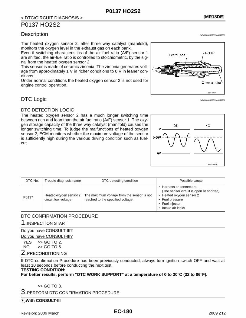
[MR18DE]P0137 HO2S2
< DTC/CIRCUIT DIAGNOSIS >
P0137 HO2S2
Description INFOID:0000000004833288
The heated oxygen sensor 2, after three way catalyst (manifold),monitors the oxygen level in the exhaust gas on each bank.Even if switching characteristics of the air fuel ratio (A/F) sensor 1are shifted, the air-fuel ratio is controlled to stoichiometric, by the sig-nal from the heated oxygen sensor 2.This sensor is made of ceramic zirconia. The zirconia generates volt-age from approximately 1 V in richer conditions to 0 V in leaner con-ditions.Under normal conditions the heated oxygen sensor 2 is not used forengine control operation.
DTC Logic INFOID:0000000004833289
DTC DETECTION LOGICThe heated oxygen sensor 2 has a much longer switching timebetween rich and lean than the air fuel ratio (A/F) sensor 1. The oxy-gen storage capacity of the three way catalyst (manifold) causes thelonger switching time. To judge the malfunctions of heated oxygensensor 2, ECM monitors whether the maximum voltage of the sensoris sufficiently high during the various driving condition such as fuel-cut.
DTC CONFIRMATION PROCEDURE
1.INSPECTION START
Do you have CONSULT-III?Do you have CONSULT-III?YES >> GO TO 2.NO >> GO TO 5.
2.PRECONDITIONING
If DTC confirmation Procedure has been previously conducted, always turn ignition switch OFF and wait atleast 10 seconds before conducting the next test.TESTING CONDITION:For better results, perform “DTC WORK SUPPORT” at a temperature of 0 to 30°C (32 to 86°F).
>> GO TO 3.
3.PERFORM DTC CONFIRMATION PROCEDURE
With CONSULT-III
SEF327R
SEF259VA
DTC No. Trouble diagnosis name DTC detecting condition Possible cause
P0137Heated oxygen sensor 2 circuit low voltage
The maximum voltage from the sensor is not reached to the specified voltage.
• Harness or connectors(The sensor circuit is open or shorted)
• Heated oxygen sensor 2• Fuel pressure• Fuel injector• Intake air leaks
EC-180Revision: 2009 March 2009 Z12
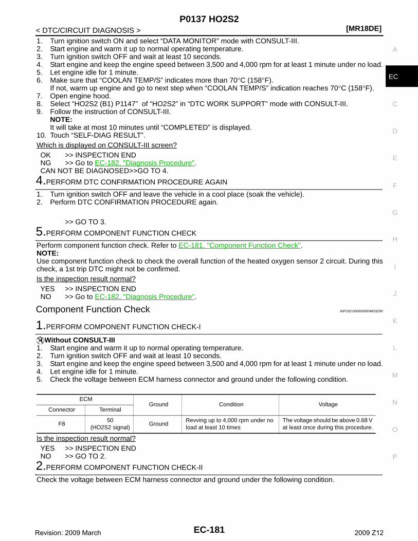
P0137 HO2S2[MR18DE]
C
D
E
F
G
H
I
J
K
L
M
A
C
N
P
O
< DTC/CIRCUIT DIAGNOSIS >
E
1. Turn ignition switch ON and select “DATA MONITOR” mode with CONSULT-III.2. Start engine and warm it up to normal operating temperature.3. Turn ignition switch OFF and wait at least 10 seconds.4. Start engine and keep the engine speed between 3,500 and 4,000 rpm for at least 1 minute under no load.5. Let engine idle for 1 minute.6. Make sure that “COOLAN TEMP/S” indicates more than 70°C (158°F).
If not, warm up engine and go to next step when “COOLAN TEMP/S” indication reaches 70°C (158°F).7. Open engine hood.8. Select “HO2S2 (B1) P1147” of “HO2S2” in “DTC WORK SUPPORT” mode with CONSULT-III.9. Follow the instruction of CONSULT-III.
NOTE:It will take at most 10 minutes until “COMPLETED” is displayed.
10. Touch “SELF-DIAG RESULT”.Which is displayed on CONSULT-III screen?OK >> INSPECTION ENDNG >> Go to EC-182, "Diagnosis Procedure".CAN NOT BE DIAGNOSED>>GO TO 4.
4.PERFORM DTC CONFIRMATION PROCEDURE AGAIN
1. Turn ignition switch OFF and leave the vehicle in a cool place (soak the vehicle).2. Perform DTC CONFIRMATION PROCEDURE again.
>> GO TO 3.
5.PERFORM COMPONENT FUNCTION CHECK
Perform component function check. Refer to EC-181, "Component Function Check".NOTE:Use component function check to check the overall function of the heated oxygen sensor 2 circuit. During thischeck, a 1st trip DTC might not be confirmed.Is the inspection result normal?YES >> INSPECTION ENDNO >> Go to EC-182, "Diagnosis Procedure".
Component Function Check INFOID:0000000004833290
1.PERFORM COMPONENT FUNCTION CHECK-I
Without CONSULT-III1. Start engine and warm it up to normal operating temperature.2. Turn ignition switch OFF and wait at least 10 seconds.3. Start engine and keep the engine speed between 3,500 and 4,000 rpm for at least 1 minute under no load.4. Let engine idle for 1 minute.5. Check the voltage between ECM harness connector and ground under the following condition.
Is the inspection result normal?YES >> INSPECTION ENDNO >> GO TO 2.
2.PERFORM COMPONENT FUNCTION CHECK-II
Check the voltage between ECM harness connector and ground under the following condition.
ECMGround Condition Voltage
Connector Terminal
F850
(HO2S2 signal)Ground
Revving up to 4,000 rpm under no load at least 10 times
The voltage should be above 0.68 V at least once during this procedure.
EC-181Revision: 2009 March 2009 Z12
[MR18DE]P0137 HO2S2
< DTC/CIRCUIT DIAGNOSIS >
Is the inspection result normal?YES >> INSPECTION ENDNO >> GO TO 3.
3.PERFORM COMPONENT FUNCTION CHECK-III
Check the voltage between ECM harness connector and ground under the following condition.
Is the inspection result normal?YES >> INSPECTION ENDNO >> Go to EC-182, "Diagnosis Procedure".
Diagnosis Procedure INFOID:0000000004833292
1.CHECK GROUND CONNECTION
1. Turn ignition switch OFF.2. Check ground connection E38. Refer to GI-37, "Circuit Inspection".Is the inspection result normal?YES >> GO TO 2.NO >> Repair or replace ground connection.
2.CLEAR THE MIXTURE RATIO SELF-LEARNING VALUE
1. Clear the mixture ratio self-learning value. Refer to EC-19, "MIXTURE RATIO SELF-LEARNING VALUECLEAR : Special Repair Requirement".
2. Run engine for at least 10 minutes at idle speed.Is the 1st trip DTC P0171 detected? Is it difficult to start engine?YES >> Perform trouble diagnosis for DTC P0171. Refer to EC-200, "DTC Logic".NO >> GO TO 3.
3.CHECK HO2S2 GROUND CIRCUIT FOR OPEN AND SHORT
1. Turn ignition switch OFF.2. Disconnect heated oxygen sensor 2 (HO2S2) harness connector.3. Disconnect ECM harness connector.4. Check the continuity between HO2S2 harness connector and ECM harness connector.
5. Also check harness for short to ground and short to power.Is the inspection result normal?YES >> GO TO 4.NO >> Repair open circuit or short to ground or short to power in harness or connectors.
4.CHECK HO2S2 INPUT SIGNAL CIRCUIT FOR OPEN AND SHORT
1. Check the continuity between HO2S2 harness connector and ECM harness connector.
ECMGround Condition Voltage
Connector Terminal
F850
(HO2S2 signal)Ground
Keeping engine speed at idle for 10 minutes
The voltage should be above 0.68 V at least once during this procedure.
ECMGround Condition Voltage
Connector Terminal
F850
(HO2S2 signal)Ground
Coasting from 80 km/h (50 MPH) in D position (CVT), 4th gear position (M/T)
The voltage should be above 0.68 V at least once during this procedure.
HO2S2 ECMContinuity
Connector Terminal Connector Terminal
F30 1 F8 59 Existed
EC-182Revision: 2009 March 2009 Z12
P0137 HO2S2[MR18DE]
C
D
E
F
G
H
I
J
K
L
M
A
C
N
P
O
< DTC/CIRCUIT DIAGNOSIS >
E2. Check the continuity between HO2S2 harness connector and ground, or ECM harness connector and
ground.
3. Also check harness for short to power.Is the inspection result normal?YES >> GO TO 5.NO >> Repair open circuit or short to ground or short to power in harness or connectors.
5.CHECK HEATED OXYGEN SENSOR 2
Refer to EC-183, "Component Inspection".Is the inspection result normal?YES >> GO TO 7.NO >> GO TO 6.
6.REPLACE HEATED OXYGEN SENSOR 2
Replace heated oxygen sensor 2.CAUTION:• Discard any sensor which has been dropped from a height of more than 0.5 m (19.7 in) onto a hard
surface such as a concrete floor; use a new one.• Before installing new sensor, clean exhaust system threads using Oxygen Sensor Thread Cleaner
[commercial service tool (J-43897-18 or J43897-12)] and approved Anti-seize Lubricant (commercialservice tool).
>> INSPECTION END
7.CHECK INTERMITTENT INCIDENT
Refer to GI-34, "Intermittent Incident".
>> INSPECTION END
Component Inspection INFOID:0000000004833293
1.INSPECTION START
Do you have CONSULT-III?Do you have CONSULT-III?YES >> GO TO 2.NO >> GO TO 3.
2.CHECK HEATED OXYGEN SENSOR 2
With CONSULT-III1. Turn ignition switch ON and select “DATA MONITOR” mode with CONSULT-III.2. Start engine and warm it up to normal operating temperature.3. Turn ignition switch OFF and wait at least 10 seconds.
HO2S2 ECMContinuity
Connector Terminal Connector Terminal
F30 4 F8 50 Existed
HO2S2Ground Continuity
Connector Terminal
F30 4 Ground Not existed
ECMGround Continuity
Connector Terminal
F8 50 Ground Not existed
EC-183Revision: 2009 March 2009 Z12
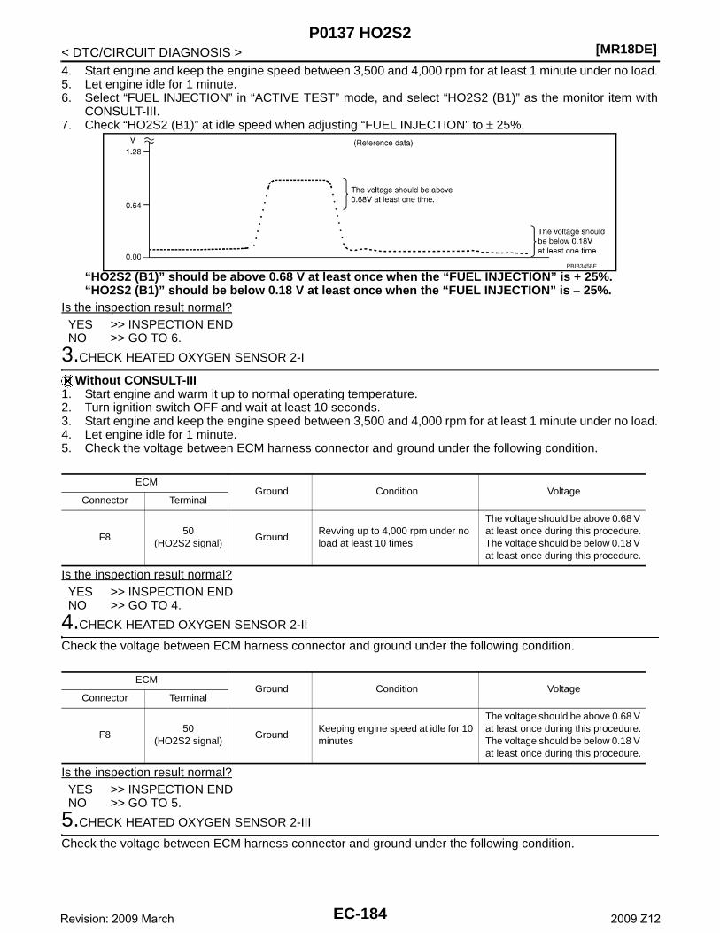
[MR18DE]P0137 HO2S2
< DTC/CIRCUIT DIAGNOSIS >4. Start engine and keep the engine speed between 3,500 and 4,000 rpm for at least 1 minute under no load.5. Let engine idle for 1 minute.6. Select “FUEL INJECTION” in “ACTIVE TEST” mode, and select “HO2S2 (B1)” as the monitor item with
CONSULT-III.7. Check “HO2S2 (B1)” at idle speed when adjusting “FUEL INJECTION” to ± 25%.
“HO2S2 (B1)” should be above 0.68 V at least once when the “FUEL INJECTION” is + 25%.“HO2S2 (B1)” should be below 0.18 V at least once when the “FUEL INJECTION” is − 25%.
Is the inspection result normal?YES >> INSPECTION ENDNO >> GO TO 6.
3.CHECK HEATED OXYGEN SENSOR 2-I
Without CONSULT-III1. Start engine and warm it up to normal operating temperature.2. Turn ignition switch OFF and wait at least 10 seconds.3. Start engine and keep the engine speed between 3,500 and 4,000 rpm for at least 1 minute under no load.4. Let engine idle for 1 minute.5. Check the voltage between ECM harness connector and ground under the following condition.
Is the inspection result normal?YES >> INSPECTION ENDNO >> GO TO 4.
4.CHECK HEATED OXYGEN SENSOR 2-II
Check the voltage between ECM harness connector and ground under the following condition.
Is the inspection result normal?YES >> INSPECTION ENDNO >> GO TO 5.
5.CHECK HEATED OXYGEN SENSOR 2-III
Check the voltage between ECM harness connector and ground under the following condition.
PBIB3458E
ECMGround Condition Voltage
Connector Terminal
F850
(HO2S2 signal)Ground
Revving up to 4,000 rpm under no load at least 10 times
The voltage should be above 0.68 V at least once during this procedure.The voltage should be below 0.18 V at least once during this procedure.
ECMGround Condition Voltage
Connector Terminal
F850
(HO2S2 signal)Ground
Keeping engine speed at idle for 10 minutes
The voltage should be above 0.68 V at least once during this procedure.The voltage should be below 0.18 V at least once during this procedure.
EC-184Revision: 2009 March 2009 Z12

P0137 HO2S2[MR18DE]
C
D
E
F
G
H
I
J
K
L
M
A
C
N
P
O
< DTC/CIRCUIT DIAGNOSIS >
E
Is the inspection result normal?YES >> INSPECTION ENDNO >> GO TO 6.
6.REPLACE HEATED OXYGEN SENSOR 2
Replace heated oxygen sensor 2.CAUTION:• Discard any sensor which has been dropped from a height of more than 0.5 m (19.7 in) onto a hard
surface such as a concrete floor; use a new one.• Before installing new sensor, clean exhaust system threads using Oxygen Sensor Thread Cleaner
[commercial service tool (J-43897-18 or J43897-12)] and approved Anti-seize Lubricant (commercialservice tool).
>> INSPECTION END
ECMGround Condition Voltage
Connector Terminal
F850
(HO2S2 signal)Ground
Coasting from 80 km/h (50 MPH) in D position (CVT), 4th gear position (M/T)
The voltage should be above 0.68 V at least once during this procedure.The voltage should be below 0.18 V at least once during this procedure.
EC-185Revision: 2009 March 2009 Z12
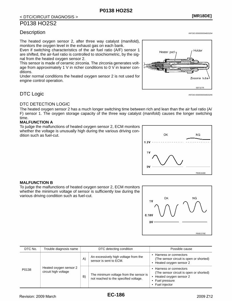
[MR18DE]P0138 HO2S2
< DTC/CIRCUIT DIAGNOSIS >
P0138 HO2S2
Description INFOID:0000000004833294
The heated oxygen sensor 2, after three way catalyst (manifold),monitors the oxygen level in the exhaust gas on each bank.Even if switching characteristics of the air fuel ratio (A/F) sensor 1are shifted, the air-fuel ratio is controlled to stoichiometric, by the sig-nal from the heated oxygen sensor 2.This sensor is made of ceramic zirconia. The zirconia generates volt-age from approximately 1 V in richer conditions to 0 V in leaner con-ditions.Under normal conditions the heated oxygen sensor 2 is not used forengine control operation.
DTC Logic INFOID:0000000004833295
DTC DETECTION LOGICThe heated oxygen sensor 2 has a much longer switching time between rich and lean than the air fuel ratio (A/F) sensor 1. The oxygen storage capacity of the three way catalyst (manifold) causes the longer switchingtime.MALFUNCTION ATo judge the malfunctions of heated oxygen sensor 2, ECM monitorswhether the voltage is unusually high during the various driving con-dition such as fuel-cut.
MALFUNCTION BTo judge the malfunctions of heated oxygen sensor 2, ECM monitorswhether the minimum voltage of sensor is sufficiently low during thevarious driving condition such as fuel-cut.
SEF327R
PBIB1848E
PBIB2376E
DTC No. Trouble diagnosis name DTC detecting condition Possible cause
P0138Heated oxygen sensor 2 circuit high voltage
A)An excessively high voltage from the sensor is sent to ECM.
• Harness or connectors(The sensor circuit is open or shorted)
• Heated oxygen sensor 2
B)The minimum voltage from the sensor is not reached to the specified voltage.
• Harness or connectors(The sensor circuit is open or shorted)
• Heated oxygen sensor 2• Fuel pressure• Fuel injector
EC-186Revision: 2009 March 2009 Z12
P0138 HO2S2[MR18DE]
C
D
E
F
G
H
I
J
K
L
M
A
C
N
P
O
< DTC/CIRCUIT DIAGNOSIS >
E
DTC CONFIRMATION PROCEDURE
1.PRECONDITIONING
If DTC Confirmation Procedure has been previously conducted, always turn ignition switch OFF and wait atleast 10 seconds before conducting the next test.
>> GO TO 2.
2.PERFORM DTC CONFIRMATION PROCEDURE FOR MALFUNCTION A
1. Start engine and warm it up to normal operating temperature.2. Turn ignition switch OFF and wait at least 10 seconds.3. Start engine and keep the engine speed between 3,500 and 4,000 rpm for at least 1 minute under no load.4. Let engine idle for 2 minutes.5. Check 1st trip DTC.Is 1st trip DTC detected?YES >> Go to EC-188, "Diagnosis Procedure".NO-1 >> With CONSULT-III: GO TO 3.NO-2 >> Without CONSULT-III: GO TO 5.
3.PERFORM DTC CONFIRMATION PROCEDURE FOR MALFUNCTION B
NOTE:For better results, perform “DTC WORK SUPPORT” at a temperature of 0 to 30°C (32 to 86°F).1. Turn ignition switch ON and select “DATA MONITOR” mode with CONSULT-III.2. Start engine and warm it up to normal operating temperature.3. Turn ignition switch OFF and wait at least 10 seconds.4. Start engine and keep the engine speed between 3,500 and 4,000 rpm for at least 1 minute under no load.5. Let engine idle for 1 minute.6. Make sure that “COOLAN TEMP/S” indication is more than 70°C (158°F).
If not, warm up engine and go to next step when “COOLAN TEMP/S” indication reaches 70°C (158°F).7. Open engine hood.8. Select “HO2S2 (B1) P1146” of “HO2S2” in “DTC WORK SUPPORT” mode with CONSULT-III.9. Follow the instruction of CONSULT-III.
NOTE:It will take at most 10 minutes until “COMPLETED” is displayed.
10. Touch “SELF-DIAG RESULT”.Which is displayed on CONSULT-IIIOK >> INSPECTION ENDNG >> Go to EC-188, "Diagnosis Procedure".CAN NOT BE DIAGNOSED>>GO TO 4.
4.PERFORM DTC CONFIRMATION PROCEDURE FOR MALUNCTION B AGAIN
1. Turn ignition switch OFF and leave the vehicle in a cool place (soak the vehicle).2. Perform DTC CONFIRMATION PROCEDURE again.
>> GO TO 3.
5.PERFORM COMPONENT FUNCTION CHECK FOR MALFUNCTION B
Perform component function check. Refer to EC-188, "Diagnosis Procedure".NOTE:Use component function check to check the overall function of the heated oxygen sensor 2 circuit. During thischeck, a 1st trip DTC might not be confirmed.Is the inspection result normal?YES >> INSPECTION ENDNO >> Go to EC-188, "Diagnosis Procedure".
Component Function Check INFOID:0000000004833296
1.PERFORM COMPONENT FUNCTION CHECK-I
EC-187Revision: 2009 March 2009 Z12
[MR18DE]P0138 HO2S2
< DTC/CIRCUIT DIAGNOSIS >
Without CONSULT-III1. Start engine and warm it up to normal operating temperature.2. Turn ignition switch OFF and wait at least 10 seconds.3. Start engine and keep the engine speed between 3,500 and 4,000 rpm for at least 1 minute under no load.4. Let engine idle for 1 minute.5. Check the voltage between ECM harness connector and ground under the following condition.
Is the inspection result normal?YES >> INSPECTION ENDNO >> GO TO 2.
2.PERFORM COMPONENT FUNCTION CHECK-II
Check the voltage between ECM harness connector and ground under the following condition.
Is the inspection result normal?YES >> INSPECTION ENDNO >> GO TO 3.
3.PERFORM COMPONENT FUNCTION CHECK-III
Check the voltage between ECM harness connector and ground under the following condition.
Is the inspection result normal?YES >> INSPECTION ENDNO >> Go to EC-188, "Diagnosis Procedure".
Diagnosis Procedure INFOID:0000000004833298
1.INSPECTION START
Confirm the detected malfunction (A or B). Refer to EC-186, "DTC Logic".Which malfunction is detected?A >> GO TO 2.B >> GO TO 9.
2.CHECK GROUND CONNECTION
1. Turn ignition switch OFF.2. Check ground connection E38. Refer to GI-37, "Circuit Inspection".Is the inspection result normal?YES >> GO TO 3.NO >> Repair or replace ground connection.
3.CHECK HO2S2 CONNECTOR FOR WATER
ECMGround Condition Voltage
Connector Terminal
F850
(HO2S2 signal)Ground
Revving up to 4,000 rpm under no load at least 10 times
The voltage should be above 0.18 V at least once during this procedure.
ECMGround Condition Voltage
Connector Terminal
F850
(HO2S2 signal)Ground
Keeping engine speed at idle for 10 minutes
The voltage should be above 0.18 V at least once during this procedure.
ECMGround Condition Voltage
Connector Terminal
F850
(HO2S2 signal)Ground
Coasting from 80 km/h (50 MPH) in D position (CVT), 4th gear position (M/T)
The voltage should be above 0.18 V at least once during this procedure.
EC-188Revision: 2009 March 2009 Z12
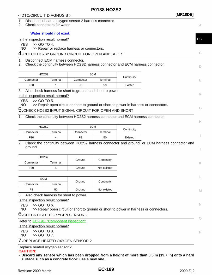
P0138 HO2S2[MR18DE]
C
D
E
F
G
H
I
J
K
L
M
A
C
N
P
O
< DTC/CIRCUIT DIAGNOSIS >
E
1. Disconnect heated oxygen sensor 2 harness connector.2. Check connectors for water.
Is the inspection result normal?YES >> GO TO 4.NO >> Repair or replace harness or connectors.
4.CHECK HO2S2 GROUND CIRCUIT FOR OPEN AND SHORT
1. Disconnect ECM harness connector.2. Check the continuity between HO2S2 harness connector and ECM harness connector.
3. Also check harness for short to ground and short to power.Is the inspection result normal?YES >> GO TO 5.NO >> Repair open circuit or short to ground or short to power in harness or connectors.
5.CHECK HO2S2 INPUT SIGNAL CIRCUIT FOR OPEN AND SHORT
1. Check the continuity between HO2S2 harness connector and ECM harness connector.
2. Check the continuity between HO2S2 harness connector and ground, or ECM harness connector andground.
3. Also check harness for short to power.Is the inspection result normal?YES >> GO TO 6.NO >> Repair open circuit or short to ground or short to power in harness or connectors.
6.CHECK HEATED OXYGEN SENSOR 2
Refer to EC-191, "Component Inspection".Is the inspection result normal?YES >> GO TO 8.NO >> GO TO 7.
7.REPLACE HEATED OXYGEN SENSOR 2
Replace heated oxygen sensor 2.CAUTION:• Discard any sensor which has been dropped from a height of more than 0.5 m (19.7 in) onto a hard
surface such as a concrete floor; use a new one.
Water should not exist.
HO2S2 ECMContinuity
Connector Terminal Connector Terminal
F30 1 F8 59 Existed
HO2S2 ECMContinuity
Connector Terminal Connector Terminal
F30 4 F8 50 Existed
HO2S2Ground Continuity
Connector Terminal
F30 4 Ground Not existed
ECMGround Continuity
Connector Terminal
F8 50 Ground Not existed
EC-189Revision: 2009 March 2009 Z12
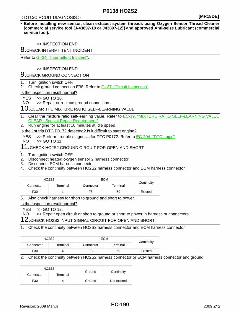
[MR18DE]P0138 HO2S2
< DTC/CIRCUIT DIAGNOSIS >• Before installing new sensor, clean exhaust system threads using Oxygen Sensor Thread Cleaner
[commercial service tool (J-43897-18 or J43897-12)] and approved Anti-seize Lubricant (commercialservice tool).
>> INSPECTION END
8.CHECK INTERMITTENT INCIDENT
Refer to GI-34, "Intermittent Incident".
>> INSPECTION END
9.CHECK GROUND CONNECTION
1. Turn ignition switch OFF.2. Check ground connection E38. Refer to GI-37, "Circuit Inspection".Is the inspection result normal?YES >> GO TO 10.NO >> Repair or replace ground connection.
10.CLEAR THE MIXTURE RATIO SELF-LEARNING VALUE
1. Clear the mixture ratio self-learning value. Refer to EC-19, "MIXTURE RATIO SELF-LEARNING VALUECLEAR : Special Repair Requirement".
2. Run engine for at least 10 minutes at idle speed.Is the 1st trip DTC P0172 detected? Is it difficult to start engine?YES >> Perform trouble diagnosis for DTC P0172. Refer to EC-204, "DTC Logic".NO >> GO TO 11.
11.CHECK HO2S2 GROUND CIRCUIT FOR OPEN AND SHORT
1. Turn ignition switch OFF.2. Disconnect heated oxygen sensor 2 harness connector.3. Disconnect ECM harness connector.4. Check the continuity between HO2S2 harness connector and ECM harness connector.
5. Also check harness for short to ground and short to power.Is the inspection result normal?YES >> GO TO 12.NO >> Repair open circuit or short to ground or short to power in harness or connectors.
12.CHECK HO2S2 INPUT SIGNAL CIRCUIT FOR OPEN AND SHORT
1. Check the continuity between HO2S2 harness connector and ECM harness connector.
2. Check the continuity between HO2S2 harness connector or ECM harness connector and ground.
HO2S2 ECMContinuity
Connector Terminal Connector Terminal
F30 1 F8 59 Existed
HO2S2 ECMContinuity
Connector Terminal Connector Terminal
F30 4 F8 50 Existed
HO2S2Ground Continuity
Connector Terminal
F30 4 Ground Not existed
EC-190Revision: 2009 March 2009 Z12
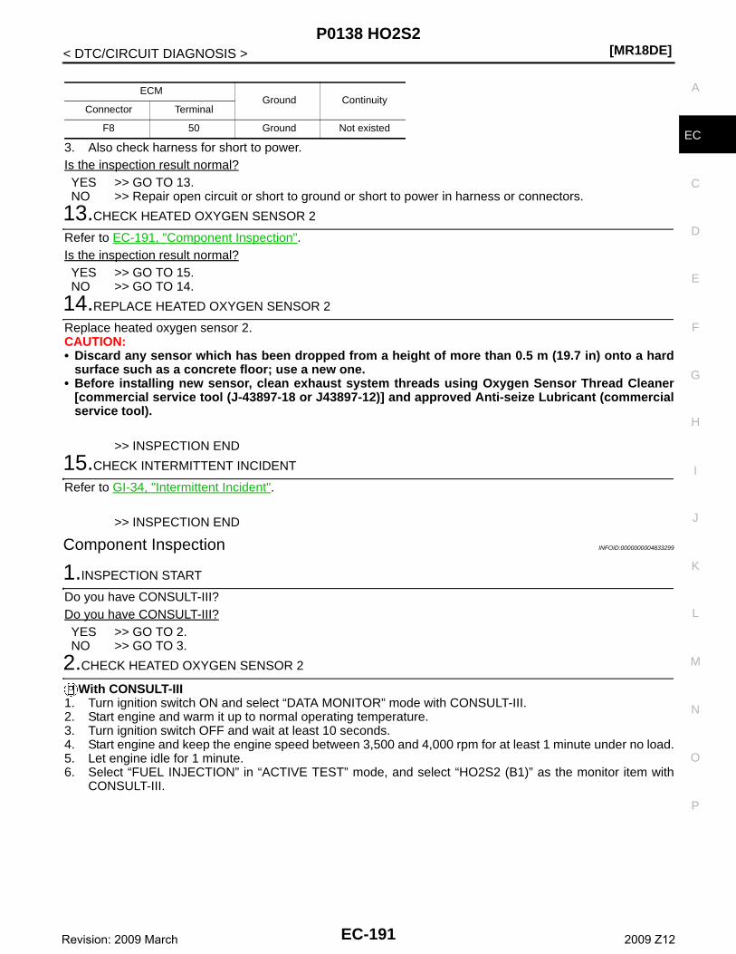
P0138 HO2S2[MR18DE]
C
D
E
F
G
H
I
J
K
L
M
A
C
N
P
O
< DTC/CIRCUIT DIAGNOSIS >
E3. Also check harness for short to power.Is the inspection result normal?YES >> GO TO 13.NO >> Repair open circuit or short to ground or short to power in harness or connectors.
13.CHECK HEATED OXYGEN SENSOR 2
Refer to EC-191, "Component Inspection".Is the inspection result normal?YES >> GO TO 15.NO >> GO TO 14.
14.REPLACE HEATED OXYGEN SENSOR 2
Replace heated oxygen sensor 2.CAUTION:• Discard any sensor which has been dropped from a height of more than 0.5 m (19.7 in) onto a hard
surface such as a concrete floor; use a new one.• Before installing new sensor, clean exhaust system threads using Oxygen Sensor Thread Cleaner
[commercial service tool (J-43897-18 or J43897-12)] and approved Anti-seize Lubricant (commercialservice tool).
>> INSPECTION END
15.CHECK INTERMITTENT INCIDENT
Refer to GI-34, "Intermittent Incident".
>> INSPECTION END
Component Inspection INFOID:0000000004833299
1.INSPECTION START
Do you have CONSULT-III?Do you have CONSULT-III?YES >> GO TO 2.NO >> GO TO 3.
2.CHECK HEATED OXYGEN SENSOR 2
With CONSULT-III1. Turn ignition switch ON and select “DATA MONITOR” mode with CONSULT-III.2. Start engine and warm it up to normal operating temperature.3. Turn ignition switch OFF and wait at least 10 seconds.4. Start engine and keep the engine speed between 3,500 and 4,000 rpm for at least 1 minute under no load.5. Let engine idle for 1 minute.6. Select “FUEL INJECTION” in “ACTIVE TEST” mode, and select “HO2S2 (B1)” as the monitor item with
CONSULT-III.
ECMGround Continuity
Connector Terminal
F8 50 Ground Not existed
EC-191Revision: 2009 March 2009 Z12
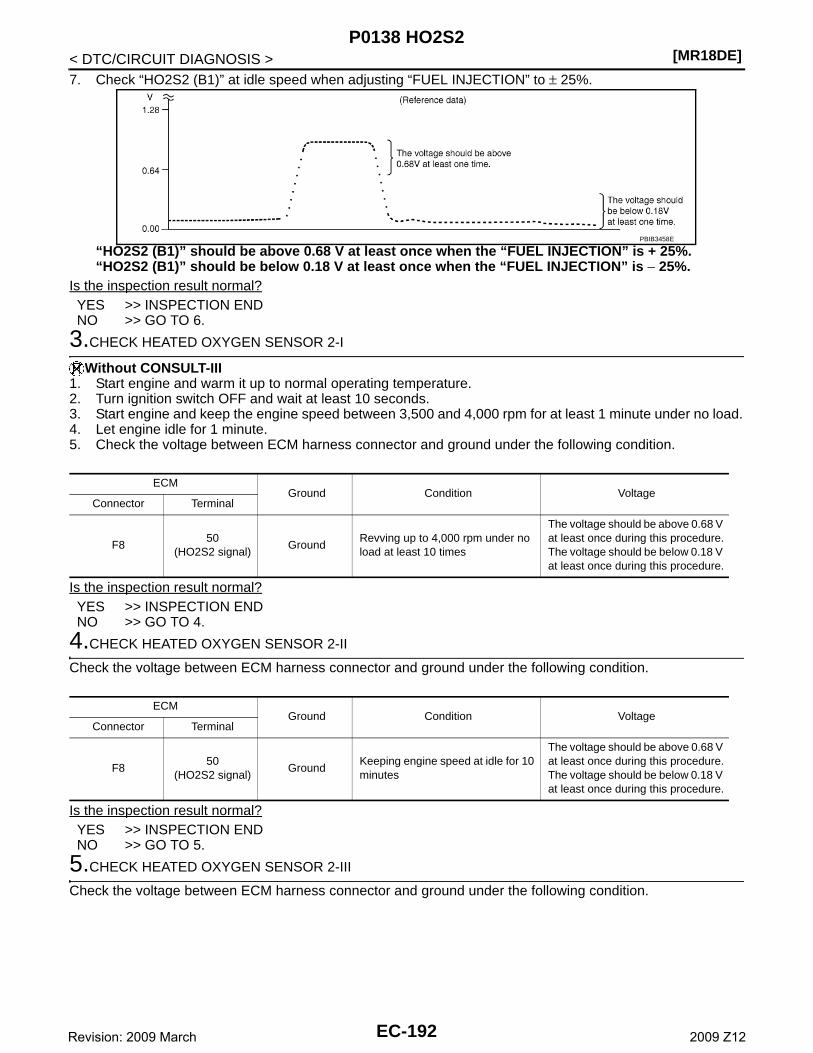
[MR18DE]P0138 HO2S2
< DTC/CIRCUIT DIAGNOSIS >7. Check “HO2S2 (B1)” at idle speed when adjusting “FUEL INJECTION” to ± 25%.
“HO2S2 (B1)” should be above 0.68 V at least once when the “FUEL INJECTION” is + 25%.“HO2S2 (B1)” should be below 0.18 V at least once when the “FUEL INJECTION” is − 25%.
Is the inspection result normal?YES >> INSPECTION ENDNO >> GO TO 6.
3.CHECK HEATED OXYGEN SENSOR 2-I
Without CONSULT-III1. Start engine and warm it up to normal operating temperature.2. Turn ignition switch OFF and wait at least 10 seconds.3. Start engine and keep the engine speed between 3,500 and 4,000 rpm for at least 1 minute under no load.4. Let engine idle for 1 minute.5. Check the voltage between ECM harness connector and ground under the following condition.
Is the inspection result normal?YES >> INSPECTION ENDNO >> GO TO 4.
4.CHECK HEATED OXYGEN SENSOR 2-II
Check the voltage between ECM harness connector and ground under the following condition.
Is the inspection result normal?YES >> INSPECTION ENDNO >> GO TO 5.
5.CHECK HEATED OXYGEN SENSOR 2-III
Check the voltage between ECM harness connector and ground under the following condition.
PBIB3458E
ECMGround Condition Voltage
Connector Terminal
F850
(HO2S2 signal)Ground
Revving up to 4,000 rpm under no load at least 10 times
The voltage should be above 0.68 V at least once during this procedure.The voltage should be below 0.18 V at least once during this procedure.
ECMGround Condition Voltage
Connector Terminal
F850
(HO2S2 signal)Ground
Keeping engine speed at idle for 10 minutes
The voltage should be above 0.68 V at least once during this procedure.The voltage should be below 0.18 V at least once during this procedure.
EC-192Revision: 2009 March 2009 Z12
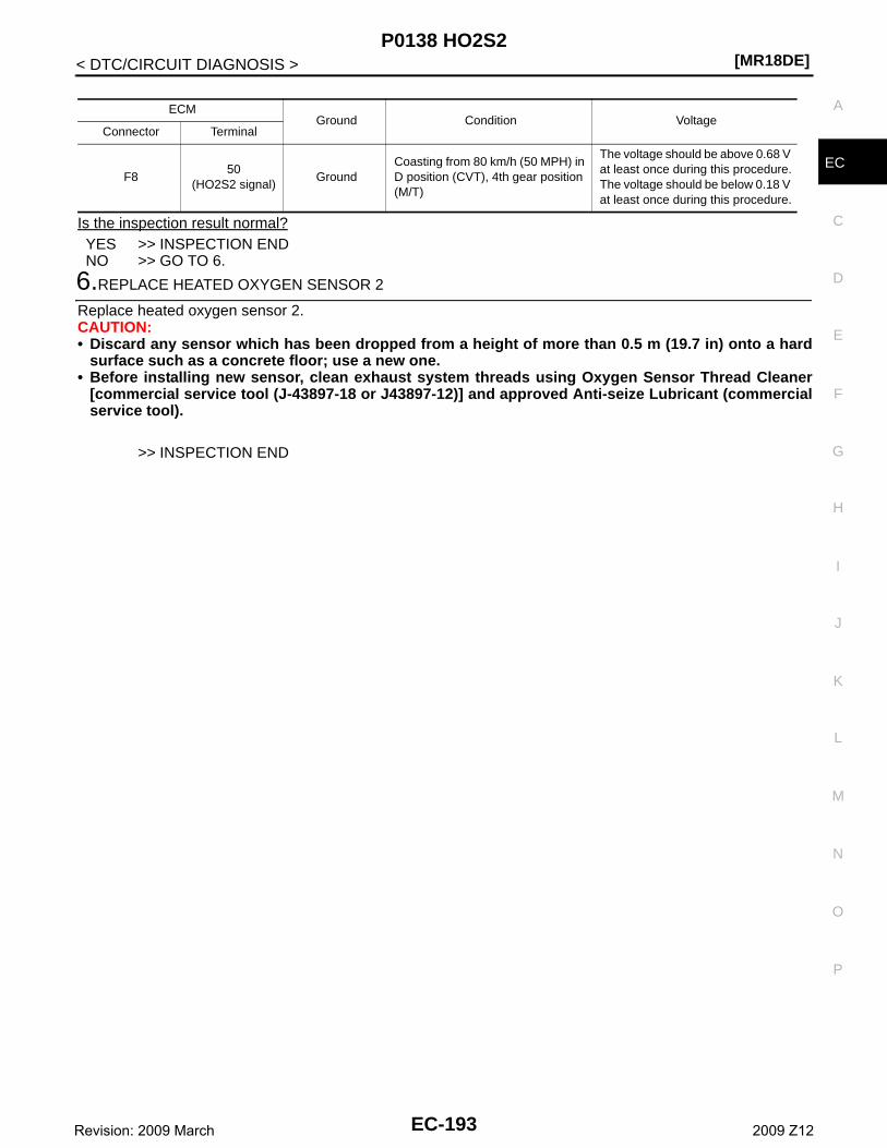
P0138 HO2S2[MR18DE]
C
D
E
F
G
H
I
J
K
L
M
A
C
N
P
O
< DTC/CIRCUIT DIAGNOSIS >
E
Is the inspection result normal?YES >> INSPECTION ENDNO >> GO TO 6.
6.REPLACE HEATED OXYGEN SENSOR 2
Replace heated oxygen sensor 2.CAUTION:• Discard any sensor which has been dropped from a height of more than 0.5 m (19.7 in) onto a hard
surface such as a concrete floor; use a new one.• Before installing new sensor, clean exhaust system threads using Oxygen Sensor Thread Cleaner
[commercial service tool (J-43897-18 or J43897-12)] and approved Anti-seize Lubricant (commercialservice tool).
>> INSPECTION END
ECMGround Condition Voltage
Connector Terminal
F850
(HO2S2 signal)Ground
Coasting from 80 km/h (50 MPH) in D position (CVT), 4th gear position (M/T)
The voltage should be above 0.68 V at least once during this procedure.The voltage should be below 0.18 V at least once during this procedure.
EC-193Revision: 2009 March 2009 Z12
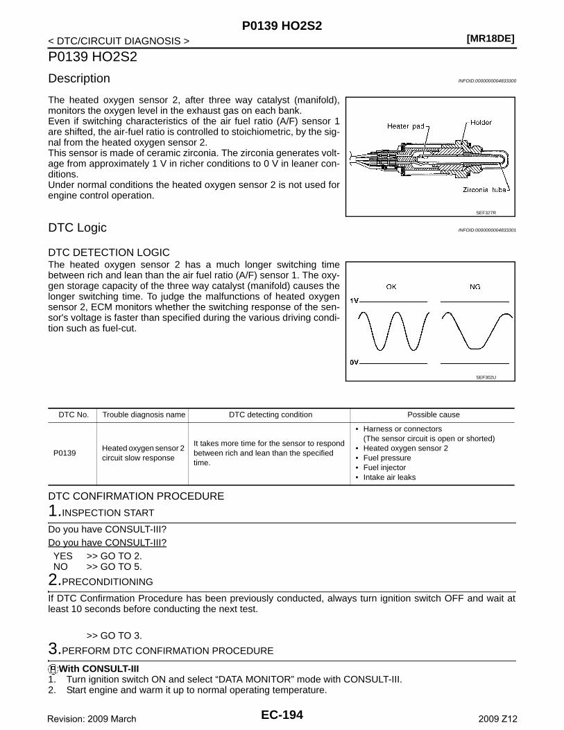
[MR18DE]P0139 HO2S2
< DTC/CIRCUIT DIAGNOSIS >
P0139 HO2S2
Description INFOID:0000000004833300
The heated oxygen sensor 2, after three way catalyst (manifold),monitors the oxygen level in the exhaust gas on each bank.Even if switching characteristics of the air fuel ratio (A/F) sensor 1are shifted, the air-fuel ratio is controlled to stoichiometric, by the sig-nal from the heated oxygen sensor 2.This sensor is made of ceramic zirconia. The zirconia generates volt-age from approximately 1 V in richer conditions to 0 V in leaner con-ditions.Under normal conditions the heated oxygen sensor 2 is not used forengine control operation.
DTC Logic INFOID:0000000004833301
DTC DETECTION LOGICThe heated oxygen sensor 2 has a much longer switching timebetween rich and lean than the air fuel ratio (A/F) sensor 1. The oxy-gen storage capacity of the three way catalyst (manifold) causes thelonger switching time. To judge the malfunctions of heated oxygensensor 2, ECM monitors whether the switching response of the sen-sor's voltage is faster than specified during the various driving condi-tion such as fuel-cut.
DTC CONFIRMATION PROCEDURE
1.INSPECTION START
Do you have CONSULT-III?Do you have CONSULT-III?YES >> GO TO 2.NO >> GO TO 5.
2.PRECONDITIONING
If DTC Confirmation Procedure has been previously conducted, always turn ignition switch OFF and wait atleast 10 seconds before conducting the next test.
>> GO TO 3.
3.PERFORM DTC CONFIRMATION PROCEDURE
With CONSULT-III1. Turn ignition switch ON and select “DATA MONITOR” mode with CONSULT-III.2. Start engine and warm it up to normal operating temperature.
SEF327R
SEF302U
DTC No. Trouble diagnosis name DTC detecting condition Possible cause
P0139Heated oxygen sensor 2 circuit slow response
It takes more time for the sensor to respond between rich and lean than the specified time.
• Harness or connectors(The sensor circuit is open or shorted)
• Heated oxygen sensor 2• Fuel pressure• Fuel injector• Intake air leaks
EC-194Revision: 2009 March 2009 Z12
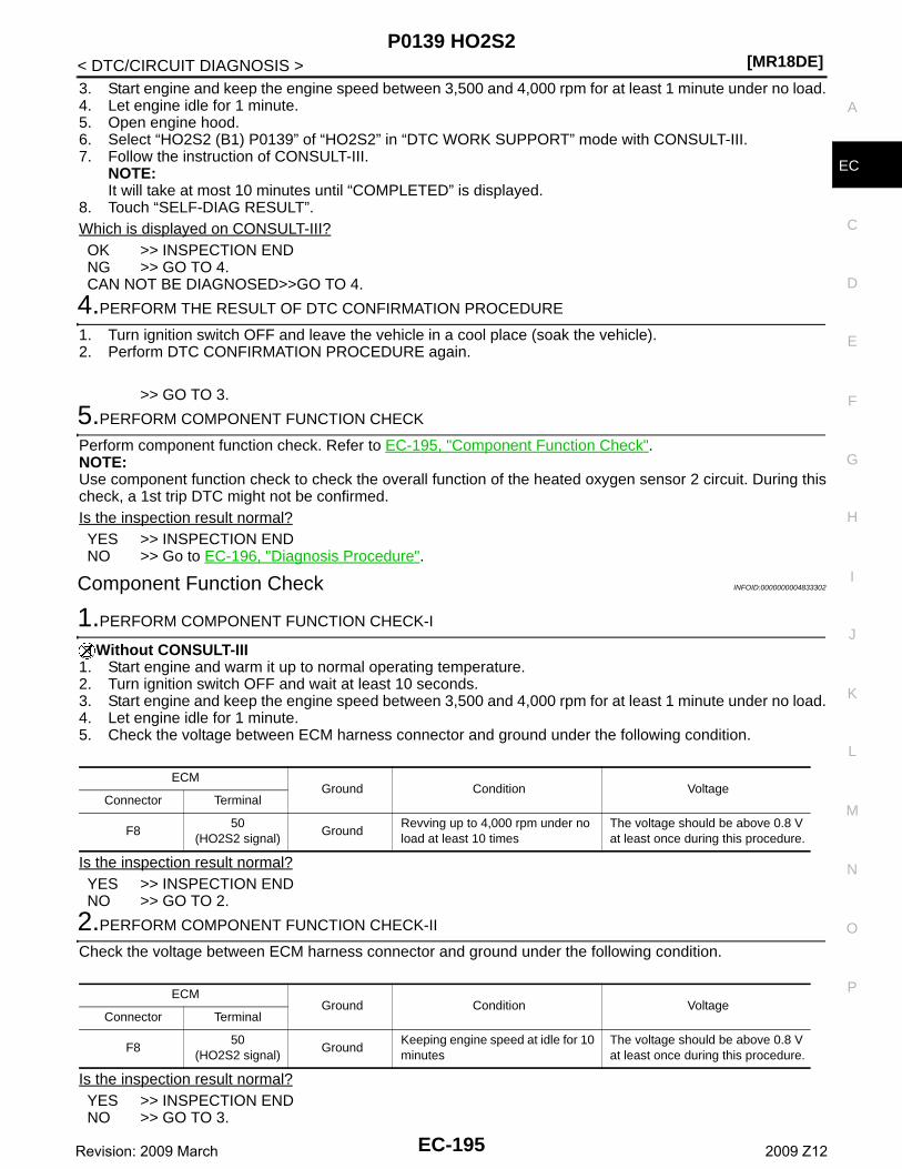
P0139 HO2S2[MR18DE]
C
D
E
F
G
H
I
J
K
L
M
A
C
N
P
O
< DTC/CIRCUIT DIAGNOSIS >
E
3. Start engine and keep the engine speed between 3,500 and 4,000 rpm for at least 1 minute under no load.4. Let engine idle for 1 minute.5. Open engine hood.6. Select “HO2S2 (B1) P0139” of “HO2S2” in “DTC WORK SUPPORT” mode with CONSULT-III.7. Follow the instruction of CONSULT-III.
NOTE:It will take at most 10 minutes until “COMPLETED” is displayed.
8. Touch “SELF-DIAG RESULT”.Which is displayed on CONSULT-III?OK >> INSPECTION ENDNG >> GO TO 4.CAN NOT BE DIAGNOSED>>GO TO 4.
4.PERFORM THE RESULT OF DTC CONFIRMATION PROCEDURE
1. Turn ignition switch OFF and leave the vehicle in a cool place (soak the vehicle).2. Perform DTC CONFIRMATION PROCEDURE again.
>> GO TO 3.
5.PERFORM COMPONENT FUNCTION CHECK
Perform component function check. Refer to EC-195, "Component Function Check".NOTE:Use component function check to check the overall function of the heated oxygen sensor 2 circuit. During thischeck, a 1st trip DTC might not be confirmed.Is the inspection result normal?YES >> INSPECTION ENDNO >> Go to EC-196, "Diagnosis Procedure".
Component Function Check INFOID:0000000004833302
1.PERFORM COMPONENT FUNCTION CHECK-I
Without CONSULT-III1. Start engine and warm it up to normal operating temperature.2. Turn ignition switch OFF and wait at least 10 seconds.3. Start engine and keep the engine speed between 3,500 and 4,000 rpm for at least 1 minute under no load.4. Let engine idle for 1 minute.5. Check the voltage between ECM harness connector and ground under the following condition.
Is the inspection result normal?YES >> INSPECTION ENDNO >> GO TO 2.
2.PERFORM COMPONENT FUNCTION CHECK-II
Check the voltage between ECM harness connector and ground under the following condition.
Is the inspection result normal?YES >> INSPECTION ENDNO >> GO TO 3.
ECMGround Condition Voltage
Connector Terminal
F850
(HO2S2 signal)Ground
Revving up to 4,000 rpm under no load at least 10 times
The voltage should be above 0.8 V at least once during this procedure.
ECMGround Condition Voltage
Connector Terminal
F850
(HO2S2 signal)Ground
Keeping engine speed at idle for 10 minutes
The voltage should be above 0.8 V at least once during this procedure.
EC-195Revision: 2009 March 2009 Z12
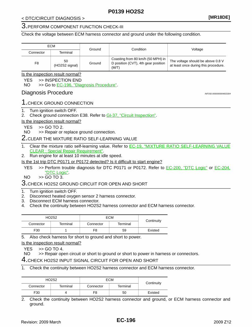
[MR18DE]P0139 HO2S2
< DTC/CIRCUIT DIAGNOSIS >
3.PERFORM COMPONENT FUNCTION CHECK-III
Check the voltage between ECM harness connector and ground under the following condition.
Is the inspection result normal?YES >> INSPECTION ENDNO >> Go to EC-196, "Diagnosis Procedure".
Diagnosis Procedure INFOID:0000000004833304
1.CHECK GROUND CONNECTION
1. Turn ignition switch OFF.2. Check ground connection E38. Refer to GI-37, "Circuit Inspection".Is the inspection result normal?YES >> GO TO 2.NO >> Repair or replace ground connection.
2.CLEAR THE MIXTURE RATIO SELF-LEARNING VALUE
1. Clear the mixture ratio self-learning value. Refer to EC-19, "MIXTURE RATIO SELF-LEARNING VALUECLEAR : Special Repair Requirement".
2. Run engine for at least 10 minutes at idle speed.Is the 1st trip DTC P0171 or P0172 detected? Is it difficult to start engine?YES >> Perform trouble diagnosis for DTC P0171 or P0172. Refer to EC-200, "DTC Logic" or EC-204,
"DTC Logic".NO >> GO TO 3.
3.CHECK HO2S2 GROUND CIRCUIT FOR OPEN AND SHORT
1. Turn ignition switch OFF.2. Disconnect heated oxygen sensor 2 harness connector.3. Disconnect ECM harness connector.4. Check the continuity between HO2S2 harness connector and ECM harness connector.
5. Also check harness for short to ground and short to power.Is the inspection result normal?YES >> GO TO 4.NO >> Repair open circuit or short to ground or short to power in harness or connectors.
4.CHECK HO2S2 INPUT SIGNAL CIRCUIT FOR OPEN AND SHORT
1. Check the continuity between HO2S2 harness connector and ECM harness connector.
2. Check the continuity between HO2S2 harness connector and ground, or ECM harness connector andground.
ECMGround Condition Voltage
Connector Terminal
F850
(HO2S2 signal)Ground
Coasting from 80 km/h (50 MPH) in D position (CVT), 4th gear position (M/T)
The voltage should be above 0.8 V at least once during this procedure.
HO2S2 ECMContinuity
Connector Terminal Connector Terminal
F30 1 F8 59 Existed
HO2S2 ECMContinuity
Connector Terminal Connector Terminal
F30 4 F8 50 Existed
EC-196Revision: 2009 March 2009 Z12
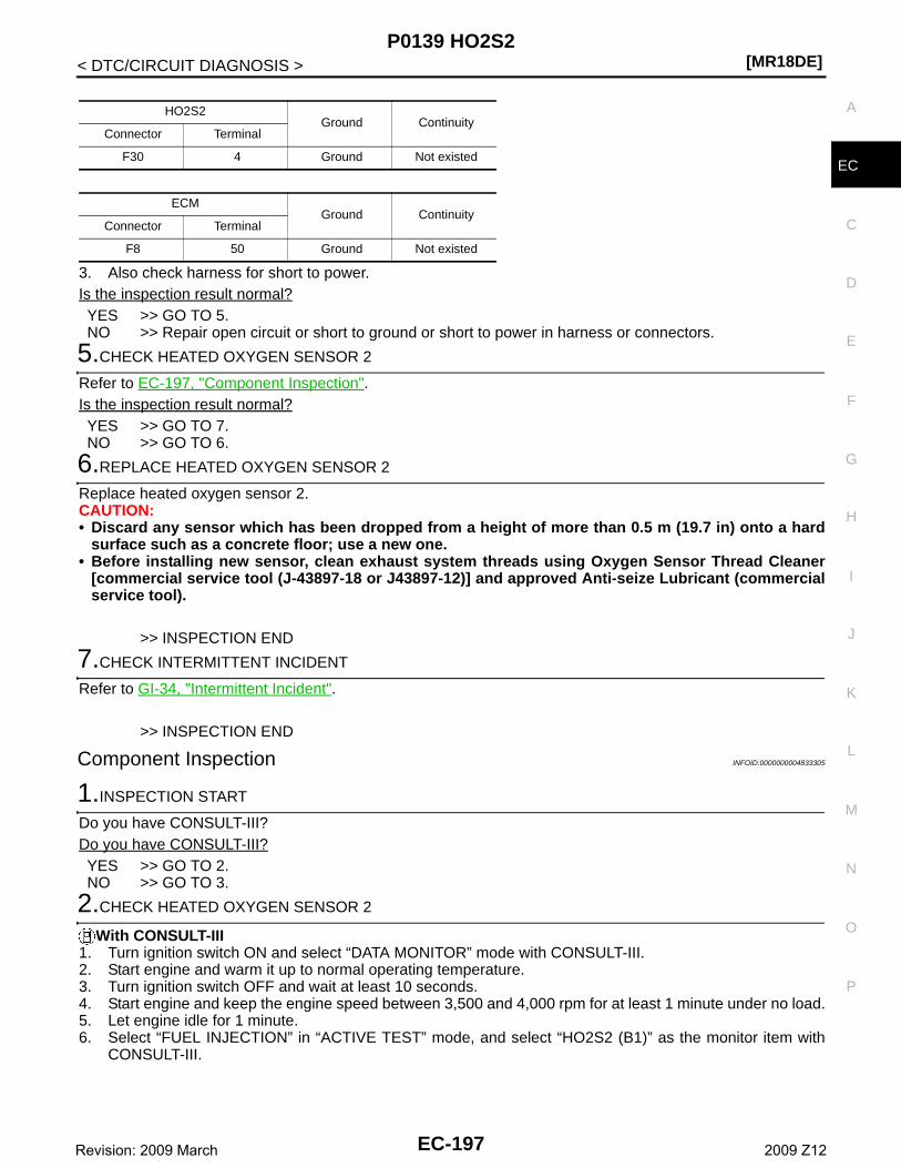
P0139 HO2S2[MR18DE]
C
D
E
F
G
H
I
J
K
L
M
A
C
N
P
O
< DTC/CIRCUIT DIAGNOSIS >
E
3. Also check harness for short to power.Is the inspection result normal?YES >> GO TO 5.NO >> Repair open circuit or short to ground or short to power in harness or connectors.
5.CHECK HEATED OXYGEN SENSOR 2
Refer to EC-197, "Component Inspection".Is the inspection result normal?YES >> GO TO 7.NO >> GO TO 6.
6.REPLACE HEATED OXYGEN SENSOR 2
Replace heated oxygen sensor 2.CAUTION:• Discard any sensor which has been dropped from a height of more than 0.5 m (19.7 in) onto a hard
surface such as a concrete floor; use a new one.• Before installing new sensor, clean exhaust system threads using Oxygen Sensor Thread Cleaner
[commercial service tool (J-43897-18 or J43897-12)] and approved Anti-seize Lubricant (commercialservice tool).
>> INSPECTION END
7.CHECK INTERMITTENT INCIDENT
Refer to GI-34, "Intermittent Incident".
>> INSPECTION END
Component Inspection INFOID:0000000004833305
1.INSPECTION START
Do you have CONSULT-III?Do you have CONSULT-III?YES >> GO TO 2.NO >> GO TO 3.
2.CHECK HEATED OXYGEN SENSOR 2
With CONSULT-III1. Turn ignition switch ON and select “DATA MONITOR” mode with CONSULT-III.2. Start engine and warm it up to normal operating temperature.3. Turn ignition switch OFF and wait at least 10 seconds.4. Start engine and keep the engine speed between 3,500 and 4,000 rpm for at least 1 minute under no load.5. Let engine idle for 1 minute.6. Select “FUEL INJECTION” in “ACTIVE TEST” mode, and select “HO2S2 (B1)” as the monitor item with
CONSULT-III.
HO2S2Ground Continuity
Connector Terminal
F30 4 Ground Not existed
ECMGround Continuity
Connector Terminal
F8 50 Ground Not existed
EC-197Revision: 2009 March 2009 Z12

[MR18DE]P0139 HO2S2
< DTC/CIRCUIT DIAGNOSIS >7. Check “HO2S2 (B1)” at idle speed when adjusting “FUEL INJECTION” to ± 25%.
“HO2S2 (B1)” should be above 0.68 V at least once when the “FUEL INJECTION” is + 25%.“HO2S2 (B1)” should be below 0.18 V at least once when the “FUEL INJECTION” is − 25%.
Is the inspection result normal?YES >> INSPECTION ENDNO >> GO TO 6.
3.CHECK HEATED OXYGEN SENSOR 2-I
Without CONSULT-III1. Start engine and warm it up to normal operating temperature.2. Turn ignition switch OFF and wait at least 10 seconds.3. Start engine and keep the engine speed between 3,500 and 4,000 rpm for at least 1 minute under no load.4. Let engine idle for 1 minute.5. Check the voltage between ECM harness connector and ground under the following condition.
Is the inspection result normal?YES >> INSPECTION ENDNO >> GO TO 4.
4.CHECK HEATED OXYGEN SENSOR 2-II
Check the voltage between ECM harness connector and ground under the following condition.
Is the inspection result normal?YES >> INSPECTION ENDNO >> GO TO 5.
5.CHECK HEATED OXYGEN SENSOR 2-III
Check the voltage between ECM harness connector and ground under the following condition.
PBIB3458E
ECMGround Condition Voltage
Connector Terminal
F850
(HO2S2 signal)Ground
Revving up to 4,000 rpm under no load at least 10 times
The voltage should be above 0.68 V at least once during this procedure.The voltage should be below 0.18 V at least once during this procedure.
ECMGround Condition Voltage
Connector Terminal
F850
(HO2S2 signal)Ground
Keeping engine speed at idle for 10 minutes
The voltage should be above 0.68 V at least once during this procedure.The voltage should be below 0.18 V at least once during this procedure.
EC-198Revision: 2009 March 2009 Z12

P0139 HO2S2[MR18DE]
C
D
E
F
G
H
I
J
K
L
M
A
C
N
P
O
< DTC/CIRCUIT DIAGNOSIS >
E
Is the inspection result normal?YES >> INSPECTION ENDNO >> GO TO 6.
6.REPLACE HEATED OXYGEN SENSOR 2
Replace heated oxygen sensor 2.CAUTION:• Discard any sensor which has been dropped from a height of more than 0.5 m (19.7 in) onto a hard
surface such as a concrete floor; use a new one.• Before installing new sensor, clean exhaust system threads using Oxygen Sensor Thread Cleaner
[commercial service tool (J-43897-18 or J43897-12)] and approved Anti-seize Lubricant (commercialservice tool).
>> INSPECTION END
ECMGround Condition Voltage
Connector Terminal
F850
(HO2S2 signal)Ground
Coasting from 80 km/h (50 MPH) in D position (CVT), 4th gear position (M/T)
The voltage should be above 0.68 V at least once during this procedure.The voltage should be below 0.18 V at least once during this procedure.
EC-199Revision: 2009 March 2009 Z12
[MR18DE]P0171 FUEL INJECTION SYSTEM FUNCTION
< DTC/CIRCUIT DIAGNOSIS >
P0171 FUEL INJECTION SYSTEM FUNCTION
DTC Logic INFOID:0000000004833306
DTC DETECTION LOGICWith the Air/Fuel Mixture Ratio Self-Learning Control, the actual mixture ratio can be brought closely to thetheoretical mixture ratio based on the mixture ratio feedback signal from the A/F sensors 1. The ECM calcu-lates the necessary compensation to correct the offset between the actual and the theoretical ratios.In case the amount of the compensation value is extremely large (The actual mixture ratio is too lean.), theECM judges the condition as the fuel injection system malfunction and lights up the MIL (2 trip detection logic).
DTC CONFIRMATION PROCEDURE
1.PRECONDITIONING
If DTC Confirmation Procedure has been previously conducted, always turn ignition switch OFF and wait atleast 10 seconds before conducting the next test.
>> GO TO 2.
2.PERFORM DTC CONFIRMATION PROCEDURE-I
1. Clear the mixture ratio self-learning value. Refer to EC-19, "MIXTURE RATIO SELF-LEARNING VALUECLEAR : Special Repair Requirement".
2. Start engine.Is it difficult to start engine?YES >> GO TO 3.NO >> GO TO 4.
3.RESTART ENGINE
If it is difficult to start engine, the fuel injection system has a malfunction, too.Crank engine while depressing accelerator pedal.NOTE:When depressing accelerator pedal three-fourths (3/4) or more, the control system does not start theengine. Do not depress accelerator pedal too much.Does engine start?YES >> Go to EC-201, "Diagnosis Procedure".NO >> Check exhaust and intake air leak visually.
4.PERFORM DTC CONFIRMATION PROCEDURE-II
1. Start engine and let it idle for at least 5 minutes.2. Check 1st trip DTC.Is 1st trip DTC detected?YES >> Go to EC-201, "Diagnosis Procedure".NO >> GO TO 5.
Sensor Input signal to ECM ECM function Actuator
A/F sensor 1Density of oxygen in exhaust gas(Mixture ratio feedback signal)
Fuel injection control Fuel injector
DTC No. Trouble diagnosis name DTC detecting condition Possible cause
P0171Fuel injection system too lean
• Fuel injection system does not operate properly.• The amount of mixture ratio compensation is too
large. (The mixture ratio is too lean.)
• Intake air leaks• A/F sensor 1• Fuel injector• Exhaust gas leaks• Incorrect fuel pressure• Lack of fuel• Mass air flow sensor• Incorrect PCV hose connection
EC-200Revision: 2009 March 2009 Z12
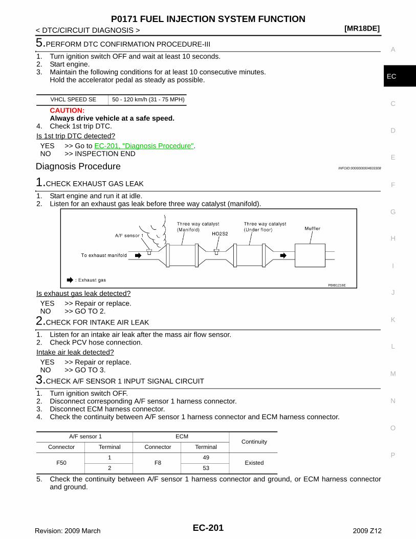
P0171 FUEL INJECTION SYSTEM FUNCTION[MR18DE]
C
D
E
F
G
H
I
J
K
L
M
A
C
N
P
O
< DTC/CIRCUIT DIAGNOSIS >
E
5.PERFORM DTC CONFIRMATION PROCEDURE-III
1. Turn ignition switch OFF and wait at least 10 seconds.2. Start engine.3. Maintain the following conditions for at least 10 consecutive minutes.
Hold the accelerator pedal as steady as possible.
CAUTION:Always drive vehicle at a safe speed.
4. Check 1st trip DTC.Is 1st trip DTC detected?YES >> Go to EC-201, "Diagnosis Procedure".NO >> INSPECTION END
Diagnosis Procedure INFOID:0000000004833308
1.CHECK EXHAUST GAS LEAK
1. Start engine and run it at idle.2. Listen for an exhaust gas leak before three way catalyst (manifold).
Is exhaust gas leak detected?YES >> Repair or replace.NO >> GO TO 2.
2.CHECK FOR INTAKE AIR LEAK
1. Listen for an intake air leak after the mass air flow sensor.2. Check PCV hose connection.Intake air leak detected?YES >> Repair or replace.NO >> GO TO 3.
3.CHECK A/F SENSOR 1 INPUT SIGNAL CIRCUIT
1. Turn ignition switch OFF.2. Disconnect corresponding A/F sensor 1 harness connector.3. Disconnect ECM harness connector.4. Check the continuity between A/F sensor 1 harness connector and ECM harness connector.
5. Check the continuity between A/F sensor 1 harness connector and ground, or ECM harness connectorand ground.
VHCL SPEED SE 50 - 120 km/h (31 - 75 MPH)
PBIB1216E
A/F sensor 1 ECMContinuity
Connector Terminal Connector Terminal
F501
F849
Existed2 53
EC-201Revision: 2009 March 2009 Z12
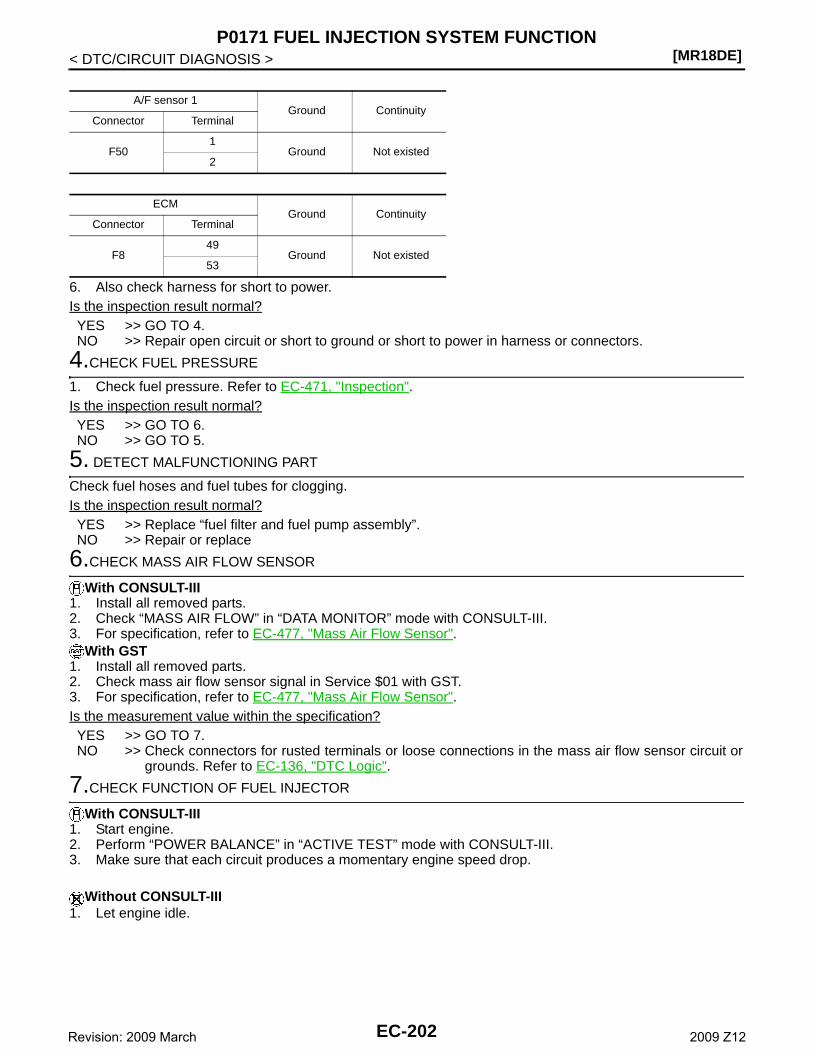
[MR18DE]P0171 FUEL INJECTION SYSTEM FUNCTION
< DTC/CIRCUIT DIAGNOSIS >
6. Also check harness for short to power.Is the inspection result normal?YES >> GO TO 4.NO >> Repair open circuit or short to ground or short to power in harness or connectors.
4.CHECK FUEL PRESSURE
1. Check fuel pressure. Refer to EC-471, "Inspection".Is the inspection result normal?YES >> GO TO 6.NO >> GO TO 5.
5. DETECT MALFUNCTIONING PART
Check fuel hoses and fuel tubes for clogging.Is the inspection result normal?YES >> Replace “fuel filter and fuel pump assembly”.NO >> Repair or replace
6.CHECK MASS AIR FLOW SENSOR
With CONSULT-III1. Install all removed parts.2. Check “MASS AIR FLOW” in “DATA MONITOR” mode with CONSULT-III.3. For specification, refer to EC-477, "Mass Air Flow Sensor".
With GST1. Install all removed parts.2. Check mass air flow sensor signal in Service $01 with GST.3. For specification, refer to EC-477, "Mass Air Flow Sensor".Is the measurement value within the specification?YES >> GO TO 7.NO >> Check connectors for rusted terminals or loose connections in the mass air flow sensor circuit or
grounds. Refer to EC-136, "DTC Logic".
7.CHECK FUNCTION OF FUEL INJECTOR
With CONSULT-III1. Start engine.2. Perform “POWER BALANCE” in “ACTIVE TEST” mode with CONSULT-III.3. Make sure that each circuit produces a momentary engine speed drop.
Without CONSULT-III1. Let engine idle.
A/F sensor 1Ground Continuity
Connector Terminal
F501
Ground Not existed2
ECMGround Continuity
Connector Terminal
F849
Ground Not existed53
EC-202Revision: 2009 March 2009 Z12
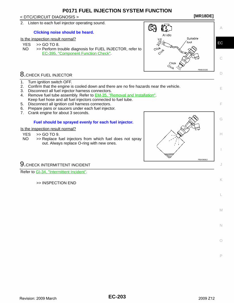
P0171 FUEL INJECTION SYSTEM FUNCTION[MR18DE]
C
D
E
F
G
H
I
J
K
L
M
A
C
N
P
O
< DTC/CIRCUIT DIAGNOSIS >
E
2. Listen to each fuel injector operating sound.
Is the inspection result normal?YES >> GO TO 8.NO >> Perform trouble diagnosis for FUEL INJECTOR, refer to
EC-395, "Component Function Check".
8.CHECK FUEL INJECTOR
1. Turn ignition switch OFF.2. Confirm that the engine is cooled down and there are no fire hazards near the vehicle.3. Disconnect all fuel injector harness connectors.4. Remove fuel tube assembly. Refer to EM-35, "Removal and Installation".
Keep fuel hose and all fuel injectors connected to fuel tube.5. Disconnect all ignition coil harness connectors.6. Prepare pans or saucers under each fuel injector.7. Crank engine for about 3 seconds.
Is the inspection result normal?YES >> GO TO 9.NO >> Replace fuel injectors from which fuel does not spray
out. Always replace O-ring with new ones.
9.CHECK INTERMITTENT INCIDENT
Refer to GI-34, "Intermittent Incident".
>> INSPECTION END
Clicking noise should be heard.
PBIB3332E
Fuel should be sprayed evenly for each fuel injector.
PBIA9666J
EC-203Revision: 2009 March 2009 Z12
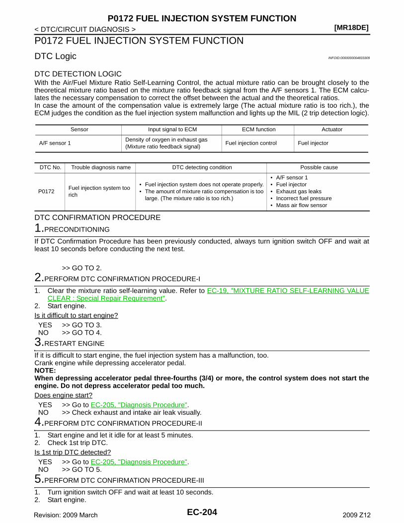
[MR18DE]P0172 FUEL INJECTION SYSTEM FUNCTION
< DTC/CIRCUIT DIAGNOSIS >
P0172 FUEL INJECTION SYSTEM FUNCTION
DTC Logic INFOID:0000000004833309
DTC DETECTION LOGICWith the Air/Fuel Mixture Ratio Self-Learning Control, the actual mixture ratio can be brought closely to thetheoretical mixture ratio based on the mixture ratio feedback signal from the A/F sensors 1. The ECM calcu-lates the necessary compensation to correct the offset between the actual and the theoretical ratios.In case the amount of the compensation value is extremely large (The actual mixture ratio is too rich.), theECM judges the condition as the fuel injection system malfunction and lights up the MIL (2 trip detection logic).
DTC CONFIRMATION PROCEDURE
1.PRECONDITIONING
If DTC Confirmation Procedure has been previously conducted, always turn ignition switch OFF and wait atleast 10 seconds before conducting the next test.
>> GO TO 2.
2.PERFORM DTC CONFIRMATION PROCEDURE-I
1. Clear the mixture ratio self-learning value. Refer to EC-19, "MIXTURE RATIO SELF-LEARNING VALUECLEAR : Special Repair Requirement".
2. Start engine.Is it difficult to start engine?YES >> GO TO 3.NO >> GO TO 4.
3.RESTART ENGINE
If it is difficult to start engine, the fuel injection system has a malfunction, too.Crank engine while depressing accelerator pedal.NOTE:When depressing accelerator pedal three-fourths (3/4) or more, the control system does not start theengine. Do not depress accelerator pedal too much.Does engine start?YES >> Go to EC-205, "Diagnosis Procedure".NO >> Check exhaust and intake air leak visually.
4.PERFORM DTC CONFIRMATION PROCEDURE-II
1. Start engine and let it idle for at least 5 minutes.2. Check 1st trip DTC.Is 1st trip DTC detected?YES >> Go to EC-205, "Diagnosis Procedure".NO >> GO TO 5.
5.PERFORM DTC CONFIRMATION PROCEDURE-III
1. Turn ignition switch OFF and wait at least 10 seconds.2. Start engine.
Sensor Input signal to ECM ECM function Actuator
A/F sensor 1Density of oxygen in exhaust gas(Mixture ratio feedback signal)
Fuel injection control Fuel injector
DTC No. Trouble diagnosis name DTC detecting condition Possible cause
P0172Fuel injection system too rich
• Fuel injection system does not operate properly.• The amount of mixture ratio compensation is too
large. (The mixture ratio is too rich.)
• A/F sensor 1• Fuel injector• Exhaust gas leaks• Incorrect fuel pressure• Mass air flow sensor
EC-204Revision: 2009 March 2009 Z12
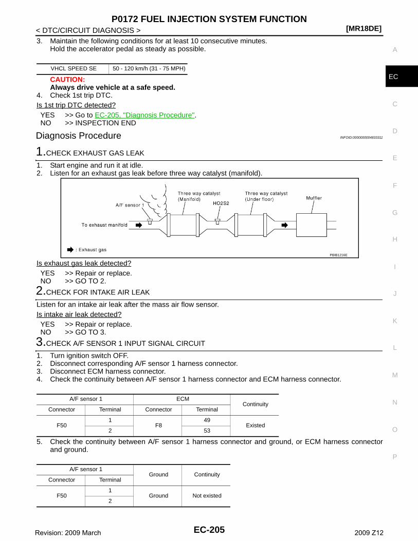
P0172 FUEL INJECTION SYSTEM FUNCTION[MR18DE]
C
D
E
F
G
H
I
J
K
L
M
A
C
N
P
O
< DTC/CIRCUIT DIAGNOSIS >
E
3. Maintain the following conditions for at least 10 consecutive minutes.Hold the accelerator pedal as steady as possible.
CAUTION:Always drive vehicle at a safe speed.
4. Check 1st trip DTC.Is 1st trip DTC detected?YES >> Go to EC-205, "Diagnosis Procedure".NO >> INSPECTION END
Diagnosis Procedure INFOID:0000000004833311
1.CHECK EXHAUST GAS LEAK
1. Start engine and run it at idle.2. Listen for an exhaust gas leak before three way catalyst (manifold).
Is exhaust gas leak detected?YES >> Repair or replace.NO >> GO TO 2.
2.CHECK FOR INTAKE AIR LEAK
Listen for an intake air leak after the mass air flow sensor.Is intake air leak detected?YES >> Repair or replace.NO >> GO TO 3.
3.CHECK A/F SENSOR 1 INPUT SIGNAL CIRCUIT
1. Turn ignition switch OFF.2. Disconnect corresponding A/F sensor 1 harness connector.3. Disconnect ECM harness connector.4. Check the continuity between A/F sensor 1 harness connector and ECM harness connector.
5. Check the continuity between A/F sensor 1 harness connector and ground, or ECM harness connectorand ground.
VHCL SPEED SE 50 - 120 km/h (31 - 75 MPH)
PBIB1216E
A/F sensor 1 ECMContinuity
Connector Terminal Connector Terminal
F501
F849
Existed2 53
A/F sensor 1Ground Continuity
Connector Terminal
F501
Ground Not existed2
EC-205Revision: 2009 March 2009 Z12
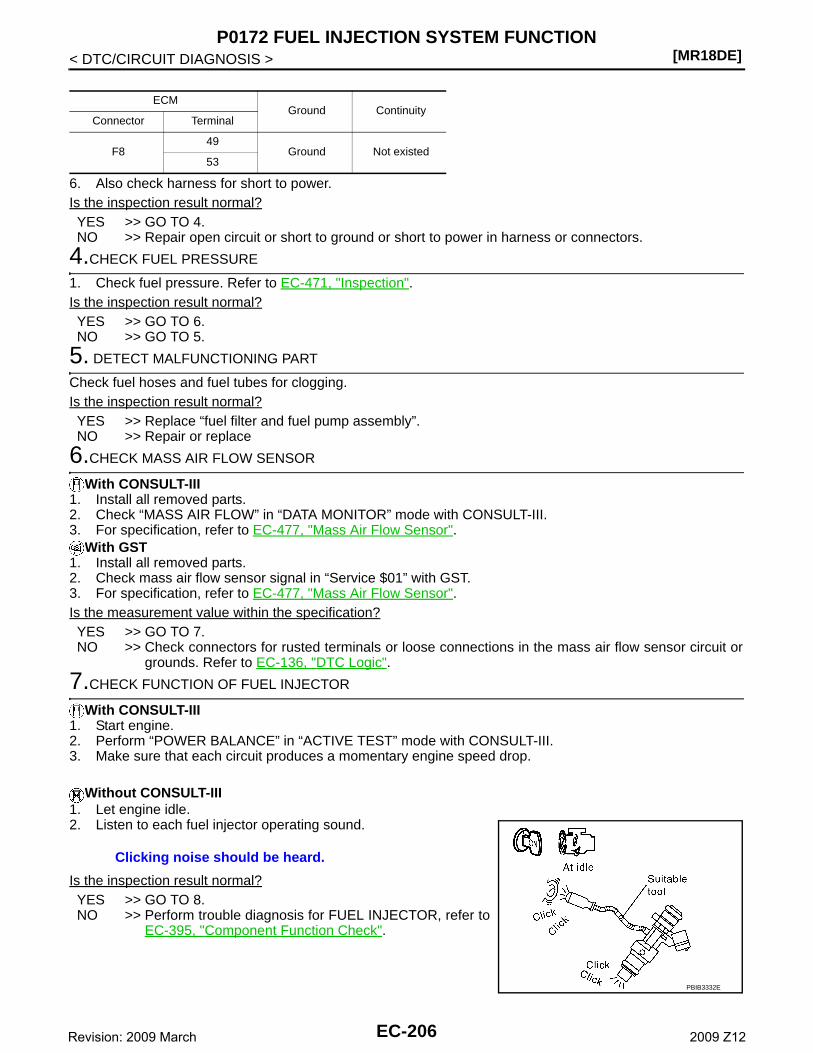
[MR18DE]P0172 FUEL INJECTION SYSTEM FUNCTION
< DTC/CIRCUIT DIAGNOSIS >
6. Also check harness for short to power.Is the inspection result normal?YES >> GO TO 4.NO >> Repair open circuit or short to ground or short to power in harness or connectors.
4.CHECK FUEL PRESSURE
1. Check fuel pressure. Refer to EC-471, "Inspection".Is the inspection result normal?YES >> GO TO 6.NO >> GO TO 5.
5. DETECT MALFUNCTIONING PART
Check fuel hoses and fuel tubes for clogging.Is the inspection result normal?YES >> Replace “fuel filter and fuel pump assembly”.NO >> Repair or replace
6.CHECK MASS AIR FLOW SENSOR
With CONSULT-III1. Install all removed parts.2. Check “MASS AIR FLOW” in “DATA MONITOR” mode with CONSULT-III.3. For specification, refer to EC-477, "Mass Air Flow Sensor".
With GST1. Install all removed parts.2. Check mass air flow sensor signal in “Service $01” with GST.3. For specification, refer to EC-477, "Mass Air Flow Sensor".Is the measurement value within the specification?YES >> GO TO 7.NO >> Check connectors for rusted terminals or loose connections in the mass air flow sensor circuit or
grounds. Refer to EC-136, "DTC Logic".
7.CHECK FUNCTION OF FUEL INJECTOR
With CONSULT-III1. Start engine.2. Perform “POWER BALANCE” in “ACTIVE TEST” mode with CONSULT-III.3. Make sure that each circuit produces a momentary engine speed drop.
Without CONSULT-III1. Let engine idle.2. Listen to each fuel injector operating sound.
Is the inspection result normal?YES >> GO TO 8.NO >> Perform trouble diagnosis for FUEL INJECTOR, refer to
EC-395, "Component Function Check".
ECMGround Continuity
Connector Terminal
F849
Ground Not existed53
Clicking noise should be heard.
PBIB3332E
EC-206Revision: 2009 March 2009 Z12
P0172 FUEL INJECTION SYSTEM FUNCTION[MR18DE]
C
D
E
F
G
H
I
J
K
L
M
A
C
N
P
O
< DTC/CIRCUIT DIAGNOSIS >
E
8.CHECK FUEL INJECTOR
1. Remove fuel injector assembly. Refer to EM-35, "Removal and Installation".Keep fuel hose and all fuel injectors connected to fuel tube.
2. Confirm that the engine is cooled down and there are no fire hazards near the vehicle.3. Disconnect all fuel injector harness connectors.4. Disconnect all ignition coil harness connectors.5. Prepare pans or saucers under each fuel injectors.6. Crank engine for about 3 seconds.
Make sure fuel does not drip from fuel injector.Is the inspection result normal?YES >> GO TO 9.NO >> Replace the fuel injectors from which fuel is dripping. Always replace O-ring with new one.
9.CHECK INTERMITTENT INCIDENT
Refer to GI-34, "Intermittent Incident".
>> INSPECTION END
EC-207Revision: 2009 March 2009 Z12
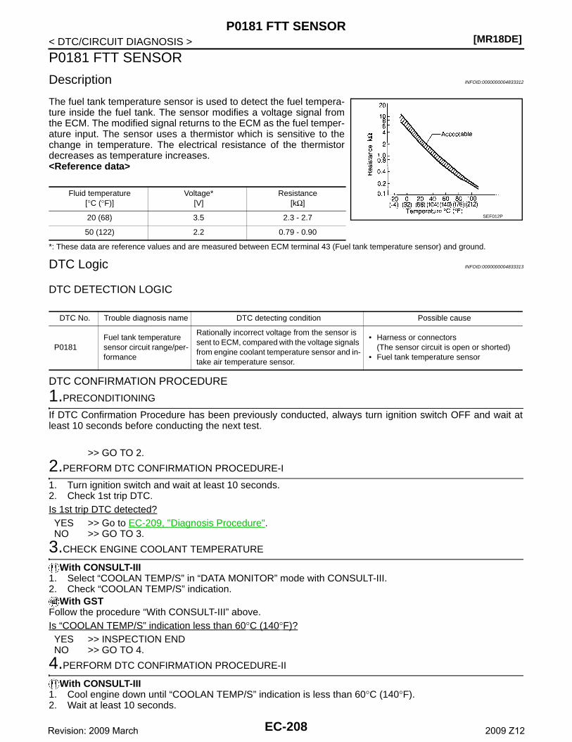
[MR18DE]P0181 FTT SENSOR
< DTC/CIRCUIT DIAGNOSIS >
P0181 FTT SENSOR
Description INFOID:0000000004833312
The fuel tank temperature sensor is used to detect the fuel tempera-ture inside the fuel tank. The sensor modifies a voltage signal fromthe ECM. The modified signal returns to the ECM as the fuel temper-ature input. The sensor uses a thermistor which is sensitive to thechange in temperature. The electrical resistance of the thermistordecreases as temperature increases.<Reference data>
*: These data are reference values and are measured between ECM terminal 43 (Fuel tank temperature sensor) and ground.
DTC Logic INFOID:0000000004833313
DTC DETECTION LOGIC
DTC CONFIRMATION PROCEDURE
1.PRECONDITIONING
If DTC Confirmation Procedure has been previously conducted, always turn ignition switch OFF and wait atleast 10 seconds before conducting the next test.
>> GO TO 2.
2.PERFORM DTC CONFIRMATION PROCEDURE-I
1. Turn ignition switch and wait at least 10 seconds.2. Check 1st trip DTC.Is 1st trip DTC detected?YES >> Go to EC-209, "Diagnosis Procedure".NO >> GO TO 3.
3.CHECK ENGINE COOLANT TEMPERATURE
With CONSULT-III1. Select “COOLAN TEMP/S” in “DATA MONITOR” mode with CONSULT-III.2. Check “COOLAN TEMP/S” indication.
With GSTFollow the procedure “With CONSULT-III” above.Is “COOLAN TEMP/S” indication less than 60°C (140°F)?YES >> INSPECTION ENDNO >> GO TO 4.
4.PERFORM DTC CONFIRMATION PROCEDURE-II
With CONSULT-III1. Cool engine down until “COOLAN TEMP/S” indication is less than 60°C (140°F).2. Wait at least 10 seconds.
Fluid temperature[°C (°F)]
Voltage*[V]
Resistance[kΩ]
20 (68) 3.5 2.3 - 2.7
50 (122) 2.2 0.79 - 0.90
SEF012P
DTC No. Trouble diagnosis name DTC detecting condition Possible cause
P0181Fuel tank temperature sensor circuit range/per-formance
Rationally incorrect voltage from the sensor is sent to ECM, compared with the voltage signals from engine coolant temperature sensor and in-take air temperature sensor.
• Harness or connectors(The sensor circuit is open or shorted)
• Fuel tank temperature sensor
EC-208Revision: 2009 March 2009 Z12
P0181 FTT SENSOR[MR18DE]
C
D
E
F
G
H
I
J
K
L
M
A
C
N
P
O
< DTC/CIRCUIT DIAGNOSIS >
E
3. Check 1st trip DTC.With GST
Follow the procedure “With CONSULT-III” above.Is 1st trip DTC detected?YES >> Go to EC-209, "Diagnosis Procedure".NO >> INSPECTION END
Diagnosis Procedure INFOID:0000000004833315
1.CHECK GROUND CONNECTION
1. Turn ignition switch OFF.2. Check ground connection E38. Refer to GI-34, "Intermittent Incident".Is the inspection result normal?YES >> GO TO 2.NO >> Repair or replace ground connection.
2.CHECK FUEL TANK TEMPERATURE SENSOR POWER SUPPLY CIRCUIT
1. Turn ignition switch OFF.2. Disconnect “fuel level sensor unit and fuel pump” harness connector.3. Turn ignition switch ON.4. Check the voltage between “fuel level sensor unit and fuel pump” harness connector and ground.
Is the inspection result normal?YES >> GO TO 4.NO >> GO TO 3.
3.DETECT MALFUNCTIONING PART
Check the following.• Harness connectors B4, M79• Harness connectors M77, E105• Harness connectors E8, F1• Harness for open or short between ECM and “fuel level sensor unit and fuel pump”
>> Repair open circuit or short to ground or short to power in harness or connector.
4.CHECK FUEL TANK TEMPERATURE SENSOR GROUND CIRCUIT FOR OPEN AND SHORT
1. Turn ignition switch OFF.2. Disconnect combination meter harness connector.3. Check the continuity between “fuel level sensor unit and fuel pump” harness connector and ECM harness
connector.
4. Also check harness for short to ground and short to power.Is the inspection result normal?YES >> GO TO 6.NO >> GO TO 5.
5.DETECT MALFUNCTIONING PART
Check the following.• Harness connectors M79, B4
Fuel level sensor unit and fuel pumpGround Voltage
Connector Terminal
B40 4 Ground Approx. 5 V
Fuel level sensor unit and fuel pump Combination meterContinuity
Connector Terminal Connector Terminal
B40 5 M34 24 Existed
EC-209Revision: 2009 March 2009 Z12
[MR18DE]P0181 FTT SENSOR
< DTC/CIRCUIT DIAGNOSIS >• Harness for open or short between “fuel level sensor unit and fuel pump” and combination meter
>> Repair open circuit or short to ground or short to power in harness or connector.
6.CHECK FUEL TANK TEMPERATURE SENSOR
Refer to EC-210, "Component Inspection".Is the inspection result normal?YES >> GO TO 7.NO >> Replace “fuel level sensor unit and fuel pump”.
7.CHECK INTERMITTENT INCIDENT
Refer to GI-34, "Intermittent Incident".
>> INSPECTION END
Component Inspection INFOID:0000000004833316
1.CHECK FUEL TANK TEMPERATURE SENSOR
1. Turn ignition switch OFF.2. Disconnect “fuel level sensor unit and fuel pump” harness connector.3. Remove fuel level sensor unit.4. Check resistance between “fuel level sensor unit and fuel pump” terminals by heating with hot water as
shown in the figure.
Is the inspection result normal?YES >> INSPECTION ENDNO >> Replace “fuel level sensor unit and fuel pump”.
Terminals Condition Resistance
4 and 5 Temperature [°C (°F)]20 (68) 2.3 - 2.7 kΩ
50 (122) 0.79 - 0.90 kΩ
EC-210Revision: 2009 March 2009 Z12
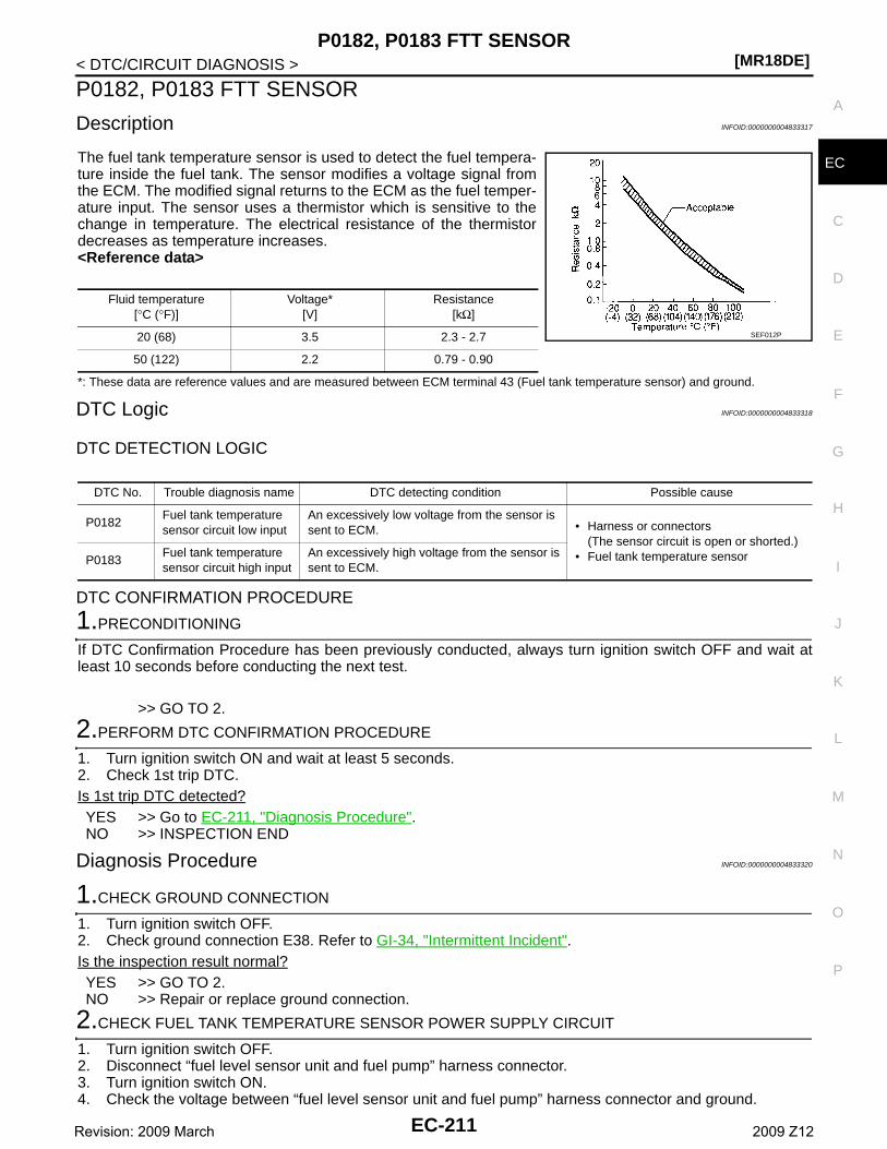
P0182, P0183 FTT SENSOR[MR18DE]
C
D
E
F
G
H
I
J
K
L
M
A
C
N
P
O
< DTC/CIRCUIT DIAGNOSIS >
E
P0182, P0183 FTT SENSOR
Description INFOID:0000000004833317
The fuel tank temperature sensor is used to detect the fuel tempera-ture inside the fuel tank. The sensor modifies a voltage signal fromthe ECM. The modified signal returns to the ECM as the fuel temper-ature input. The sensor uses a thermistor which is sensitive to thechange in temperature. The electrical resistance of the thermistordecreases as temperature increases.<Reference data>
*: These data are reference values and are measured between ECM terminal 43 (Fuel tank temperature sensor) and ground.
DTC Logic INFOID:0000000004833318
DTC DETECTION LOGIC
DTC CONFIRMATION PROCEDURE
1.PRECONDITIONING
If DTC Confirmation Procedure has been previously conducted, always turn ignition switch OFF and wait atleast 10 seconds before conducting the next test.
>> GO TO 2.
2.PERFORM DTC CONFIRMATION PROCEDURE
1. Turn ignition switch ON and wait at least 5 seconds.2. Check 1st trip DTC.Is 1st trip DTC detected?YES >> Go to EC-211, "Diagnosis Procedure".NO >> INSPECTION END
Diagnosis Procedure INFOID:0000000004833320
1.CHECK GROUND CONNECTION
1. Turn ignition switch OFF.2. Check ground connection E38. Refer to GI-34, "Intermittent Incident".Is the inspection result normal?YES >> GO TO 2.NO >> Repair or replace ground connection.
2.CHECK FUEL TANK TEMPERATURE SENSOR POWER SUPPLY CIRCUIT
1. Turn ignition switch OFF.2. Disconnect “fuel level sensor unit and fuel pump” harness connector.3. Turn ignition switch ON.4. Check the voltage between “fuel level sensor unit and fuel pump” harness connector and ground.
Fluid temperature[°C (°F)]
Voltage*[V]
Resistance[kΩ]
20 (68) 3.5 2.3 - 2.7
50 (122) 2.2 0.79 - 0.90
SEF012P
DTC No. Trouble diagnosis name DTC detecting condition Possible cause
P0182Fuel tank temperature sensor circuit low input
An excessively low voltage from the sensor is sent to ECM. • Harness or connectors
(The sensor circuit is open or shorted.)• Fuel tank temperature sensorP0183
Fuel tank temperature sensor circuit high input
An excessively high voltage from the sensor is sent to ECM.
EC-211Revision: 2009 March 2009 Z12
[MR18DE]P0182, P0183 FTT SENSOR
< DTC/CIRCUIT DIAGNOSIS >
Is the inspection result normal?YES >> GO TO 4.NO >> GO TO 3.
3.DETECT MALFUNCTIONING PART
Check the following.• Harness connectors B4, M79• Harness connectors M77, E105• Harness connectors E8, F1• Harness for open or short between ECM and “fuel level sensor unit and fuel pump”
>> Repair open circuit or short to ground or short to power in harness or connector.
4.CHECK FUEL TANK TEMPERATURE SENSOR GROUND CIRCUIT FOR OPEN AND SHORT
1. Turn ignition switch OFF.2. Disconnect combination meter harness connector.3. Check the continuity between “fuel level sensor unit and fuel pump” harness connector and ECM harness
connector.
4. Also check harness for short to ground and short to power.Is the inspection result normal?YES >> GO TO 6.NO >> GO TO 5.
5.DETECT MALFUNCTIONING PART
Check the following.• Harness connectors M79, B4• Harness for open or short between “fuel level sensor unit and fuel pump” and combination meter
>> Repair open circuit or short to ground or short to power in harness or connector.
6.CHECK FUEL TANK TEMPERATURE SENSOR
Refer to EC-212, "Component Inspection".Is the inspection result normal?YES >> GO TO 7.NO >> Replace “fuel level sensor unit and fuel pump”.
7.CHECK INTERMITTENT INCIDENT
Refer to GI-34, "Intermittent Incident".
>> INSPECTION END
Component Inspection INFOID:0000000004833321
1.CHECK FUEL TANK TEMPERATURE SENSOR
1. Turn ignition switch OFF.2. Disconnect “fuel level sensor unit and fuel pump” harness connector.3. Remove fuel level sensor unit.
Fuel level sensor unit and fuel pumpGround Voltage
Connector Terminal
B40 4 Ground Approx. 5 V
Fuel level sensor unit and fuel pump Combination meterContinuity
Connector Terminal Connector Terminal
B40 5 M34 24 Existed
EC-212Revision: 2009 March 2009 Z12
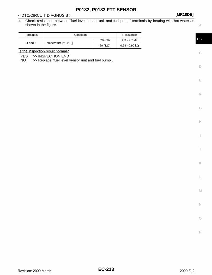
P0182, P0183 FTT SENSOR[MR18DE]
C
D
E
F
G
H
I
J
K
L
M
A
C
N
P
O
< DTC/CIRCUIT DIAGNOSIS >
E
4. Check resistance between “fuel level sensor unit and fuel pump” terminals by heating with hot water asshown in the figure.
Is the inspection result normal?YES >> INSPECTION ENDNO >> Replace “fuel level sensor unit and fuel pump”.
Terminals Condition Resistance
4 and 5 Temperature [°C (°F)]20 (68) 2.3 - 2.7 kΩ
50 (122) 0.79 - 0.90 kΩ
EC-213Revision: 2009 March 2009 Z12
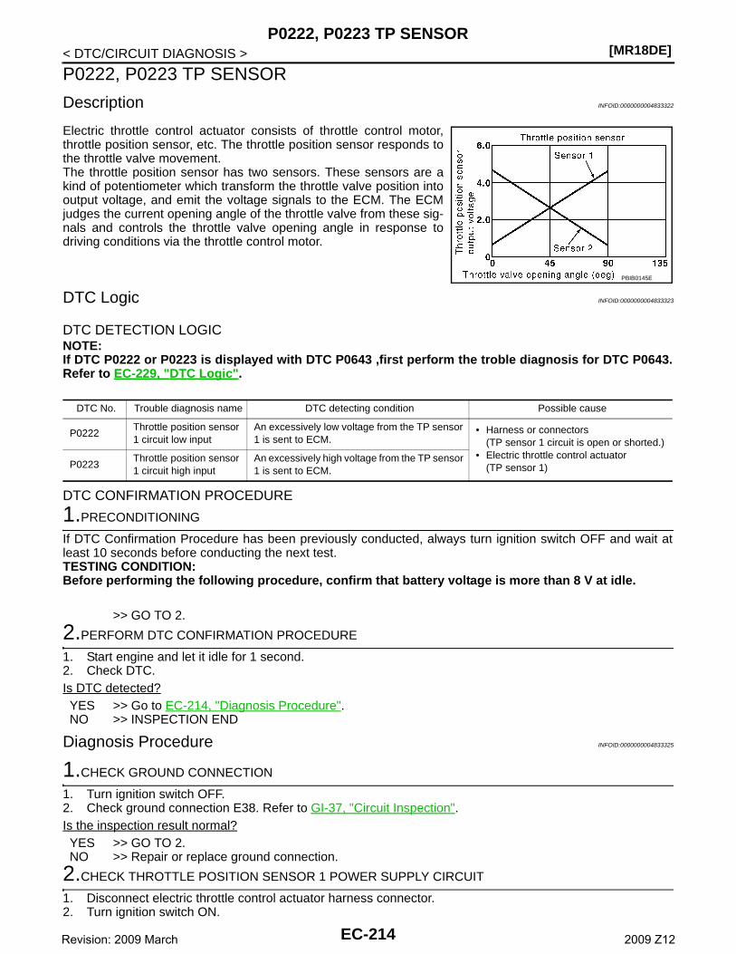
[MR18DE]P0222, P0223 TP SENSOR
< DTC/CIRCUIT DIAGNOSIS >
P0222, P0223 TP SENSOR
Description INFOID:0000000004833322
Electric throttle control actuator consists of throttle control motor,throttle position sensor, etc. The throttle position sensor responds tothe throttle valve movement. The throttle position sensor has two sensors. These sensors are akind of potentiometer which transform the throttle valve position intooutput voltage, and emit the voltage signals to the ECM. The ECMjudges the current opening angle of the throttle valve from these sig-nals and controls the throttle valve opening angle in response todriving conditions via the throttle control motor.
DTC Logic INFOID:0000000004833323
DTC DETECTION LOGICNOTE:If DTC P0222 or P0223 is displayed with DTC P0643 ,first perform the troble diagnosis for DTC P0643.Refer to EC-229, "DTC Logic".
DTC CONFIRMATION PROCEDURE
1.PRECONDITIONING
If DTC Confirmation Procedure has been previously conducted, always turn ignition switch OFF and wait atleast 10 seconds before conducting the next test.TESTING CONDITION:Before performing the following procedure, confirm that battery voltage is more than 8 V at idle.
>> GO TO 2.
2.PERFORM DTC CONFIRMATION PROCEDURE
1. Start engine and let it idle for 1 second.2. Check DTC.Is DTC detected?YES >> Go to EC-214, "Diagnosis Procedure".NO >> INSPECTION END
Diagnosis Procedure INFOID:0000000004833325
1.CHECK GROUND CONNECTION
1. Turn ignition switch OFF.2. Check ground connection E38. Refer to GI-37, "Circuit Inspection".Is the inspection result normal?YES >> GO TO 2.NO >> Repair or replace ground connection.
2.CHECK THROTTLE POSITION SENSOR 1 POWER SUPPLY CIRCUIT
1. Disconnect electric throttle control actuator harness connector.2. Turn ignition switch ON.
PBIB0145E
DTC No. Trouble diagnosis name DTC detecting condition Possible cause
P0222Throttle position sensor 1 circuit low input
An excessively low voltage from the TP sensor 1 is sent to ECM.
• Harness or connectors(TP sensor 1 circuit is open or shorted.)
• Electric throttle control actuator(TP sensor 1)P0223
Throttle position sensor 1 circuit high input
An excessively high voltage from the TP sensor 1 is sent to ECM.
EC-214Revision: 2009 March 2009 Z12
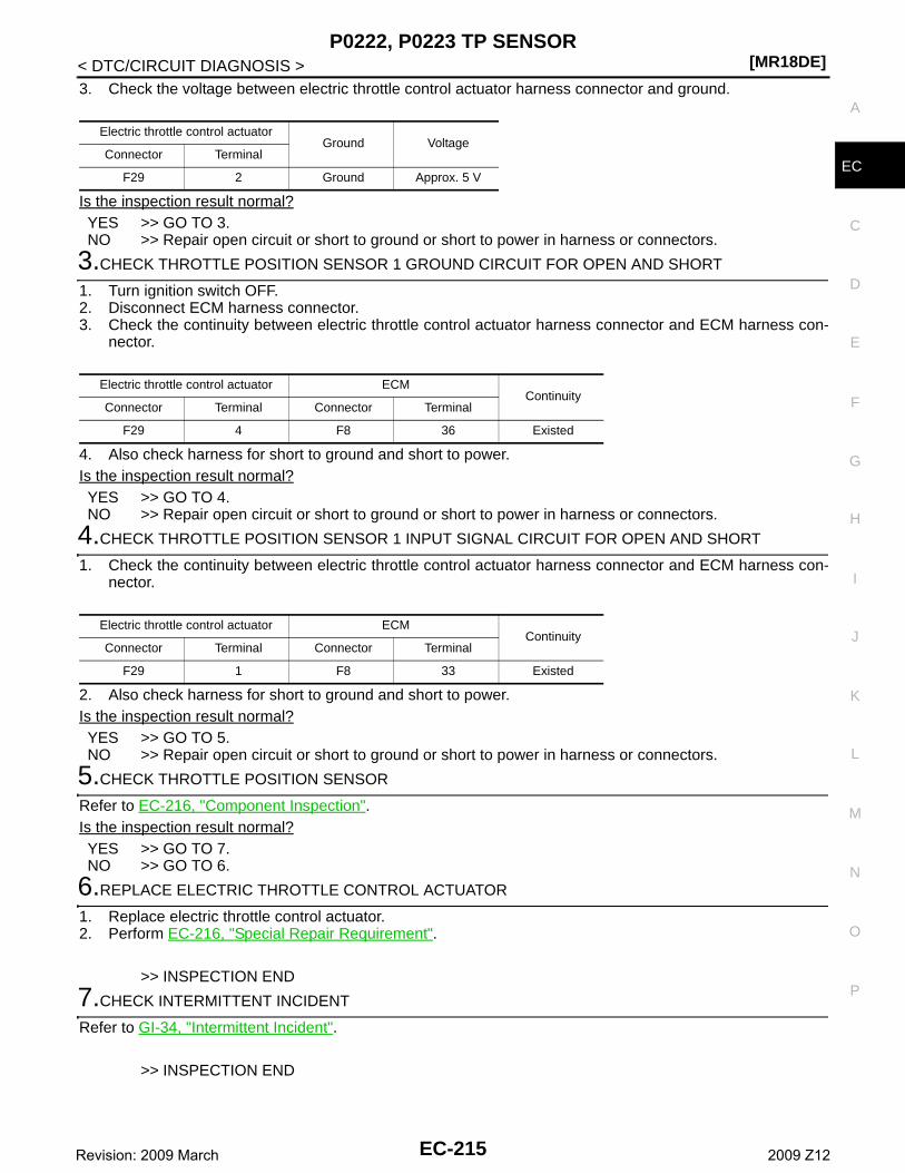
P0222, P0223 TP SENSOR[MR18DE]
C
D
E
F
G
H
I
J
K
L
M
A
C
N
P
O
< DTC/CIRCUIT DIAGNOSIS >
E
3. Check the voltage between electric throttle control actuator harness connector and ground.
Is the inspection result normal?YES >> GO TO 3.NO >> Repair open circuit or short to ground or short to power in harness or connectors.
3.CHECK THROTTLE POSITION SENSOR 1 GROUND CIRCUIT FOR OPEN AND SHORT
1. Turn ignition switch OFF.2. Disconnect ECM harness connector.3. Check the continuity between electric throttle control actuator harness connector and ECM harness con-
nector.
4. Also check harness for short to ground and short to power.Is the inspection result normal?YES >> GO TO 4.NO >> Repair open circuit or short to ground or short to power in harness or connectors.
4.CHECK THROTTLE POSITION SENSOR 1 INPUT SIGNAL CIRCUIT FOR OPEN AND SHORT
1. Check the continuity between electric throttle control actuator harness connector and ECM harness con-nector.
2. Also check harness for short to ground and short to power.Is the inspection result normal?YES >> GO TO 5.NO >> Repair open circuit or short to ground or short to power in harness or connectors.
5.CHECK THROTTLE POSITION SENSOR
Refer to EC-216, "Component Inspection".Is the inspection result normal?YES >> GO TO 7.NO >> GO TO 6.
6.REPLACE ELECTRIC THROTTLE CONTROL ACTUATOR
1. Replace electric throttle control actuator.2. Perform EC-216, "Special Repair Requirement".
>> INSPECTION END
7.CHECK INTERMITTENT INCIDENT
Refer to GI-34, "Intermittent Incident".
>> INSPECTION END
Electric throttle control actuatorGround Voltage
Connector Terminal
F29 2 Ground Approx. 5 V
Electric throttle control actuator ECMContinuity
Connector Terminal Connector Terminal
F29 4 F8 36 Existed
Electric throttle control actuator ECMContinuity
Connector Terminal Connector Terminal
F29 1 F8 33 Existed
EC-215Revision: 2009 March 2009 Z12
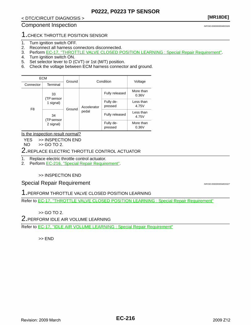
[MR18DE]P0222, P0223 TP SENSOR
< DTC/CIRCUIT DIAGNOSIS >
Component Inspection INFOID:0000000004833326
1.CHECK THROTTLE POSITION SENSOR
1. Turn ignition switch OFF.2. Reconnect all harness connectors disconnected.3. Perform EC-17, "THROTTLE VALVE CLOSED POSITION LEARNING : Special Repair Requirement".4. Turn ignition switch ON.5. Set selector lever to D (CVT) or 1st (M/T) position. 6. Check the voltage between ECM harness connector and ground.
Is the inspection result normal?YES >> INSPECTION ENDNO >> GO TO 2.
2.REPLACE ELECTRIC THROTTLE CONTROL ACTUATOR
1. Replace electric throttle control actuator.2. Perform EC-216, "Special Repair Requirement".
>> INSPECTION END
Special Repair Requirement INFOID:0000000004833327
1.PERFORM THROTTLE VALVE CLOSED POSITION LEARNING
Refer to EC-17, "THROTTLE VALVE CLOSED POSITION LEARNING : Special Repair Requirement"
>> GO TO 2.
2.PERFORM IDLE AIR VOLUME LEARNING
Refer to EC-17, "IDLE AIR VOLUME LEARNING : Special Repair Requirement"
>> END
ECMGround Condition Voltage
Connector Terminal
F8
33(TP sensor 1 signal)
GroundAccelerator pedal
Fully releasedMore than
0.36V
Fully de-pressed
Less than 4.75V
34 (TP sensor
2 signal)
Fully releasedLess than
4.75V
Fully de-pressed
More than 0.36V
EC-216Revision: 2009 March 2009 Z12
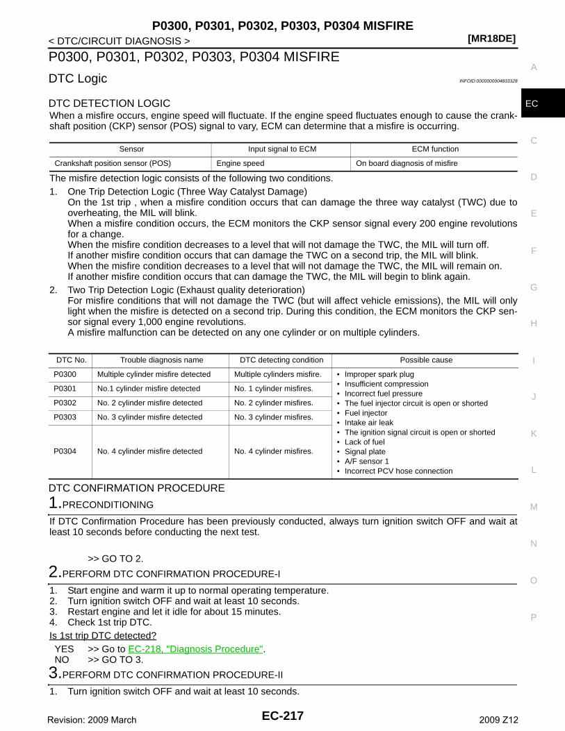
P0300, P0301, P0302, P0303, P0304 MISFIRE[MR18DE]
C
D
E
F
G
H
I
J
K
L
M
A
C
N
P
O
< DTC/CIRCUIT DIAGNOSIS >
E
P0300, P0301, P0302, P0303, P0304 MISFIRE
DTC Logic INFOID:0000000004833328
DTC DETECTION LOGICWhen a misfire occurs, engine speed will fluctuate. If the engine speed fluctuates enough to cause the crank-shaft position (CKP) sensor (POS) signal to vary, ECM can determine that a misfire is occurring.
The misfire detection logic consists of the following two conditions.1. One Trip Detection Logic (Three Way Catalyst Damage)
On the 1st trip , when a misfire condition occurs that can damage the three way catalyst (TWC) due tooverheating, the MIL will blink.When a misfire condition occurs, the ECM monitors the CKP sensor signal every 200 engine revolutionsfor a change.When the misfire condition decreases to a level that will not damage the TWC, the MIL will turn off.If another misfire condition occurs that can damage the TWC on a second trip, the MIL will blink.When the misfire condition decreases to a level that will not damage the TWC, the MIL will remain on.If another misfire condition occurs that can damage the TWC, the MIL will begin to blink again.
2. Two Trip Detection Logic (Exhaust quality deterioration)For misfire conditions that will not damage the TWC (but will affect vehicle emissions), the MIL will onlylight when the misfire is detected on a second trip. During this condition, the ECM monitors the CKP sen-sor signal every 1,000 engine revolutions.A misfire malfunction can be detected on any one cylinder or on multiple cylinders.
DTC CONFIRMATION PROCEDURE
1.PRECONDITIONING
If DTC Confirmation Procedure has been previously conducted, always turn ignition switch OFF and wait atleast 10 seconds before conducting the next test.
>> GO TO 2.
2.PERFORM DTC CONFIRMATION PROCEDURE-I
1. Start engine and warm it up to normal operating temperature.2. Turn ignition switch OFF and wait at least 10 seconds.3. Restart engine and let it idle for about 15 minutes.4. Check 1st trip DTC.Is 1st trip DTC detected?YES >> Go to EC-218, "Diagnosis Procedure".NO >> GO TO 3.
3.PERFORM DTC CONFIRMATION PROCEDURE-II
1. Turn ignition switch OFF and wait at least 10 seconds.
Sensor Input signal to ECM ECM function
Crankshaft position sensor (POS) Engine speed On board diagnosis of misfire
DTC No. Trouble diagnosis name DTC detecting condition Possible cause
P0300 Multiple cylinder misfire detected Multiple cylinders misfire. • Improper spark plug• Insufficient compression• Incorrect fuel pressure• The fuel injector circuit is open or shorted• Fuel injector• Intake air leak• The ignition signal circuit is open or shorted• Lack of fuel• Signal plate• A/F sensor 1• Incorrect PCV hose connection
P0301 No.1 cylinder misfire detected No. 1 cylinder misfires.
P0302 No. 2 cylinder misfire detected No. 2 cylinder misfires.
P0303 No. 3 cylinder misfire detected No. 3 cylinder misfires.
P0304 No. 4 cylinder misfire detected No. 4 cylinder misfires.
EC-217Revision: 2009 March 2009 Z12
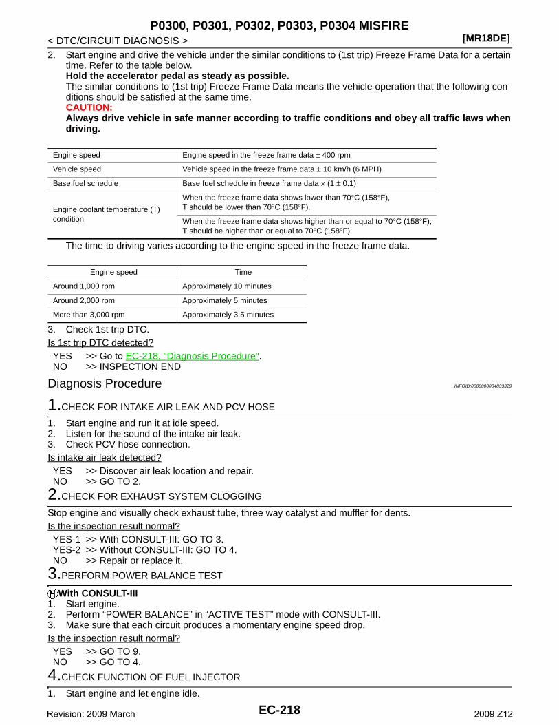
[MR18DE]P0300, P0301, P0302, P0303, P0304 MISFIRE
< DTC/CIRCUIT DIAGNOSIS >2. Start engine and drive the vehicle under the similar conditions to (1st trip) Freeze Frame Data for a certain
time. Refer to the table below.Hold the accelerator pedal as steady as possible.The similar conditions to (1st trip) Freeze Frame Data means the vehicle operation that the following con-ditions should be satisfied at the same time.CAUTION:Always drive vehicle in safe manner according to traffic conditions and obey all traffic laws whendriving.
The time to driving varies according to the engine speed in the freeze frame data.
3. Check 1st trip DTC.Is 1st trip DTC detected?YES >> Go to EC-218, "Diagnosis Procedure".NO >> INSPECTION END
Diagnosis Procedure INFOID:0000000004833329
1.CHECK FOR INTAKE AIR LEAK AND PCV HOSE
1. Start engine and run it at idle speed.2. Listen for the sound of the intake air leak.3. Check PCV hose connection.Is intake air leak detected?YES >> Discover air leak location and repair.NO >> GO TO 2.
2.CHECK FOR EXHAUST SYSTEM CLOGGING
Stop engine and visually check exhaust tube, three way catalyst and muffler for dents.Is the inspection result normal?YES-1 >> With CONSULT-III: GO TO 3.YES-2 >> Without CONSULT-III: GO TO 4.NO >> Repair or replace it.
3.PERFORM POWER BALANCE TEST
With CONSULT-III1. Start engine.2. Perform “POWER BALANCE” in “ACTIVE TEST” mode with CONSULT-III.3. Make sure that each circuit produces a momentary engine speed drop.Is the inspection result normal?YES >> GO TO 9.NO >> GO TO 4.
4.CHECK FUNCTION OF FUEL INJECTOR
1. Start engine and let engine idle.
Engine speed Engine speed in the freeze frame data ± 400 rpm
Vehicle speed Vehicle speed in the freeze frame data ± 10 km/h (6 MPH)
Base fuel schedule Base fuel schedule in freeze frame data × (1 ± 0.1)
Engine coolant temperature (T) condition
When the freeze frame data shows lower than 70°C (158°F),T should be lower than 70°C (158°F).
When the freeze frame data shows higher than or equal to 70°C (158°F),T should be higher than or equal to 70°C (158°F).
Engine speed Time
Around 1,000 rpm Approximately 10 minutes
Around 2,000 rpm Approximately 5 minutes
More than 3,000 rpm Approximately 3.5 minutes
EC-218Revision: 2009 March 2009 Z12
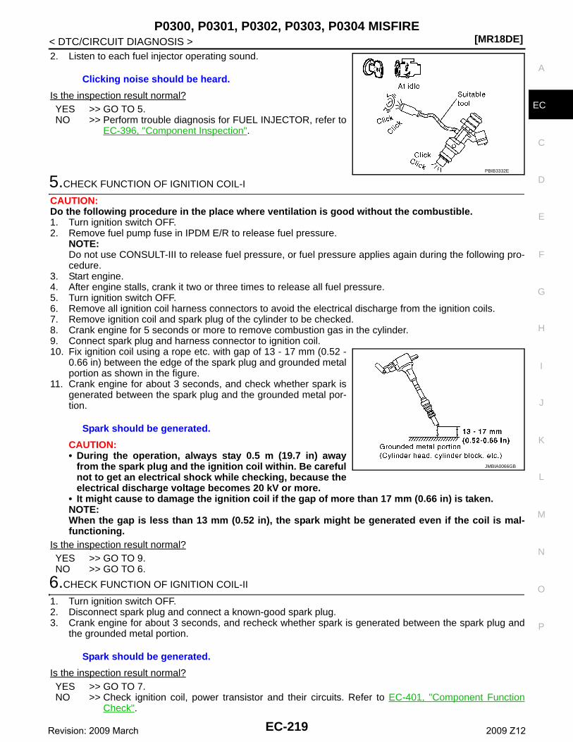
P0300, P0301, P0302, P0303, P0304 MISFIRE[MR18DE]
C
D
E
F
G
H
I
J
K
L
M
A
C
N
P
O
< DTC/CIRCUIT DIAGNOSIS >
E
2. Listen to each fuel injector operating sound.
Is the inspection result normal?YES >> GO TO 5.NO >> Perform trouble diagnosis for FUEL INJECTOR, refer to
EC-396, "Component Inspection".
5.CHECK FUNCTION OF IGNITION COIL-I
CAUTION:Do the following procedure in the place where ventilation is good without the combustible.1. Turn ignition switch OFF.2. Remove fuel pump fuse in IPDM E/R to release fuel pressure.
NOTE:Do not use CONSULT-III to release fuel pressure, or fuel pressure applies again during the following pro-cedure.
3. Start engine.4. After engine stalls, crank it two or three times to release all fuel pressure.5. Turn ignition switch OFF.6. Remove all ignition coil harness connectors to avoid the electrical discharge from the ignition coils.7. Remove ignition coil and spark plug of the cylinder to be checked.8. Crank engine for 5 seconds or more to remove combustion gas in the cylinder.9. Connect spark plug and harness connector to ignition coil.10. Fix ignition coil using a rope etc. with gap of 13 - 17 mm (0.52 -
0.66 in) between the edge of the spark plug and grounded metalportion as shown in the figure.
11. Crank engine for about 3 seconds, and check whether spark isgenerated between the spark plug and the grounded metal por-tion.
CAUTION:• During the operation, always stay 0.5 m (19.7 in) away
from the spark plug and the ignition coil within. Be carefulnot to get an electrical shock while checking, because theelectrical discharge voltage becomes 20 kV or more.
• It might cause to damage the ignition coil if the gap of more than 17 mm (0.66 in) is taken.NOTE:When the gap is less than 13 mm (0.52 in), the spark might be generated even if the coil is mal-functioning.
Is the inspection result normal?YES >> GO TO 9.NO >> GO TO 6.
6.CHECK FUNCTION OF IGNITION COIL-II
1. Turn ignition switch OFF.2. Disconnect spark plug and connect a known-good spark plug.3. Crank engine for about 3 seconds, and recheck whether spark is generated between the spark plug and
the grounded metal portion.
Is the inspection result normal?YES >> GO TO 7.NO >> Check ignition coil, power transistor and their circuits. Refer to EC-401, "Component Function
Check".
Clicking noise should be heard.
PBIB3332E
Spark should be generated.
JMBIA0066GB
Spark should be generated.
EC-219Revision: 2009 March 2009 Z12
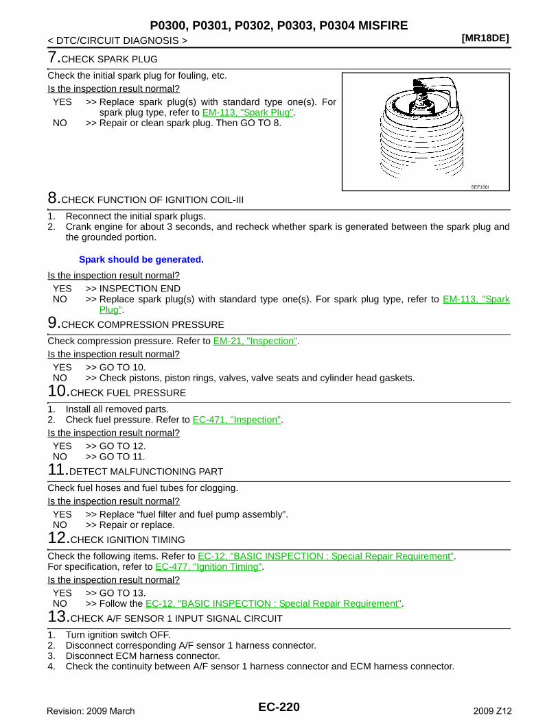
[MR18DE]P0300, P0301, P0302, P0303, P0304 MISFIRE
< DTC/CIRCUIT DIAGNOSIS >
7.CHECK SPARK PLUG
Check the initial spark plug for fouling, etc.Is the inspection result normal?YES >> Replace spark plug(s) with standard type one(s). For
spark plug type, refer to EM-113, "Spark Plug".NO >> Repair or clean spark plug. Then GO TO 8.
8.CHECK FUNCTION OF IGNITION COIL-III
1. Reconnect the initial spark plugs.2. Crank engine for about 3 seconds, and recheck whether spark is generated between the spark plug and
the grounded portion.
Is the inspection result normal?YES >> INSPECTION ENDNO >> Replace spark plug(s) with standard type one(s). For spark plug type, refer to EM-113, "Spark
Plug".
9.CHECK COMPRESSION PRESSURE
Check compression pressure. Refer to EM-21, "Inspection".Is the inspection result normal?YES >> GO TO 10.NO >> Check pistons, piston rings, valves, valve seats and cylinder head gaskets.
10.CHECK FUEL PRESSURE
1. Install all removed parts.2. Check fuel pressure. Refer to EC-471, "Inspection".Is the inspection result normal?YES >> GO TO 12.NO >> GO TO 11.
11.DETECT MALFUNCTIONING PART
Check fuel hoses and fuel tubes for clogging.Is the inspection result normal?YES >> Replace “fuel filter and fuel pump assembly”.NO >> Repair or replace.
12.CHECK IGNITION TIMING
Check the following items. Refer to EC-12, "BASIC INSPECTION : Special Repair Requirement".For specification, refer to EC-477, "Ignition Timing".Is the inspection result normal?YES >> GO TO 13.NO >> Follow the EC-12, "BASIC INSPECTION : Special Repair Requirement".
13.CHECK A/F SENSOR 1 INPUT SIGNAL CIRCUIT
1. Turn ignition switch OFF.2. Disconnect corresponding A/F sensor 1 harness connector.3. Disconnect ECM harness connector.4. Check the continuity between A/F sensor 1 harness connector and ECM harness connector.
SEF156I
Spark should be generated.
EC-220Revision: 2009 March 2009 Z12
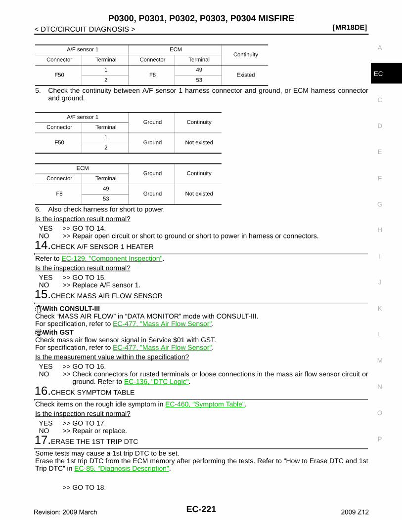
P0300, P0301, P0302, P0303, P0304 MISFIRE[MR18DE]
C
D
E
F
G
H
I
J
K
L
M
A
C
N
P
O
< DTC/CIRCUIT DIAGNOSIS >
E
5. Check the continuity between A/F sensor 1 harness connector and ground, or ECM harness connectorand ground.
6. Also check harness for short to power.Is the inspection result normal?YES >> GO TO 14.NO >> Repair open circuit or short to ground or short to power in harness or connectors.
14.CHECK A/F SENSOR 1 HEATER
Refer to EC-129, "Component Inspection".Is the inspection result normal?YES >> GO TO 15.NO >> Replace A/F sensor 1.
15.CHECK MASS AIR FLOW SENSOR
With CONSULT-IIICheck “MASS AIR FLOW” in “DATA MONITOR” mode with CONSULT-III.For specification, refer to EC-477, "Mass Air Flow Sensor".
With GSTCheck mass air flow sensor signal in Service $01 with GST.For specification, refer to EC-477, "Mass Air Flow Sensor".Is the measurement value within the specification?YES >> GO TO 16.NO >> Check connectors for rusted terminals or loose connections in the mass air flow sensor circuit or
ground. Refer to EC-136, "DTC Logic".
16.CHECK SYMPTOM TABLE
Check items on the rough idle symptom in EC-460, "Symptom Table".Is the inspection result normal?YES >> GO TO 17.NO >> Repair or replace.
17.ERASE THE 1ST TRIP DTC
Some tests may cause a 1st trip DTC to be set.Erase the 1st trip DTC from the ECM memory after performing the tests. Refer to “How to Erase DTC and 1stTrip DTC” in EC-85, "Diagnosis Description".
>> GO TO 18.
A/F sensor 1 ECMContinuity
Connector Terminal Connector Terminal
F501
F849
Existed2 53
A/F sensor 1Ground Continuity
Connector Terminal
F501
Ground Not existed2
ECMGround Continuity
Connector Terminal
F849
Ground Not existed53
EC-221Revision: 2009 March 2009 Z12
[MR18DE]P0300, P0301, P0302, P0303, P0304 MISFIRE
< DTC/CIRCUIT DIAGNOSIS >
18.CHECK INTERMITTENT INCIDENT
Refer to GI-34, "Intermittent Incident".
>> INSPECTION END
EC-222Revision: 2009 March 2009 Z12
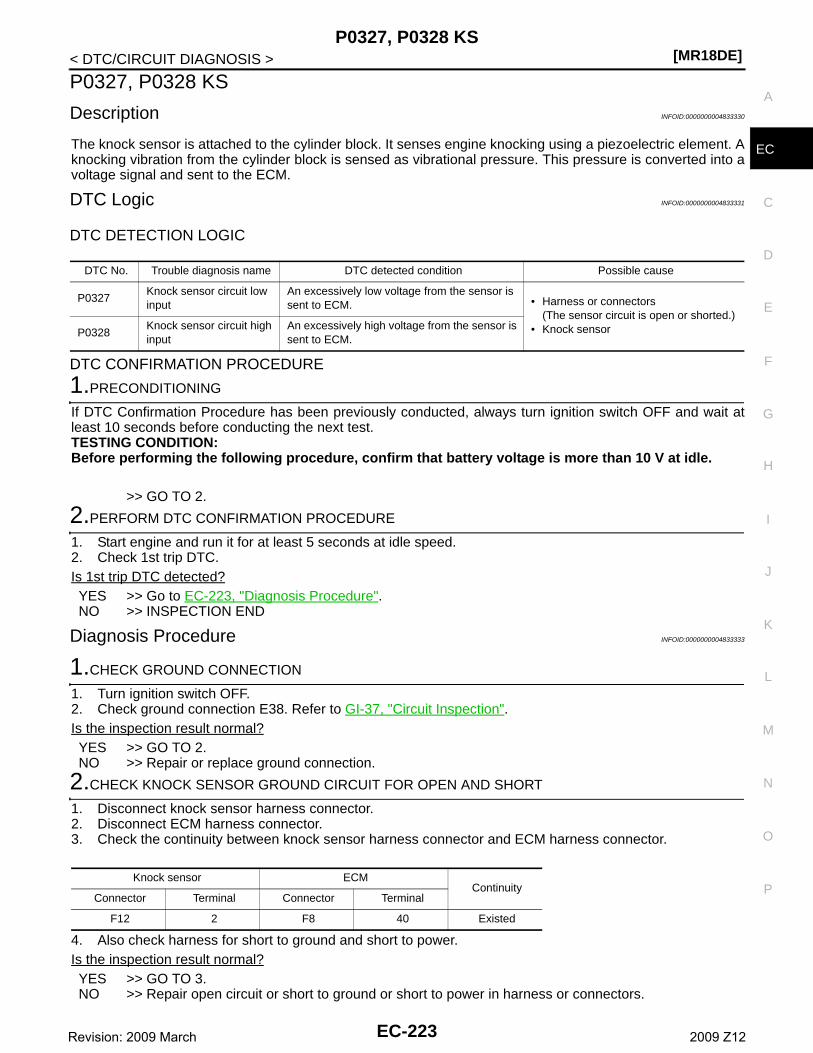
P0327, P0328 KS[MR18DE]
C
D
E
F
G
H
I
J
K
L
M
A
C
N
P
O
< DTC/CIRCUIT DIAGNOSIS >
E
P0327, P0328 KS
Description INFOID:0000000004833330
The knock sensor is attached to the cylinder block. It senses engine knocking using a piezoelectric element. Aknocking vibration from the cylinder block is sensed as vibrational pressure. This pressure is converted into avoltage signal and sent to the ECM.
DTC Logic INFOID:0000000004833331
DTC DETECTION LOGIC
DTC CONFIRMATION PROCEDURE
1.PRECONDITIONING
If DTC Confirmation Procedure has been previously conducted, always turn ignition switch OFF and wait atleast 10 seconds before conducting the next test.TESTING CONDITION:Before performing the following procedure, confirm that battery voltage is more than 10 V at idle.
>> GO TO 2.
2.PERFORM DTC CONFIRMATION PROCEDURE
1. Start engine and run it for at least 5 seconds at idle speed.2. Check 1st trip DTC.Is 1st trip DTC detected?YES >> Go to EC-223, "Diagnosis Procedure".NO >> INSPECTION END
Diagnosis Procedure INFOID:0000000004833333
1.CHECK GROUND CONNECTION
1. Turn ignition switch OFF.2. Check ground connection E38. Refer to GI-37, "Circuit Inspection".Is the inspection result normal?YES >> GO TO 2.NO >> Repair or replace ground connection.
2.CHECK KNOCK SENSOR GROUND CIRCUIT FOR OPEN AND SHORT
1. Disconnect knock sensor harness connector.2. Disconnect ECM harness connector.3. Check the continuity between knock sensor harness connector and ECM harness connector.
4. Also check harness for short to ground and short to power.Is the inspection result normal?YES >> GO TO 3.NO >> Repair open circuit or short to ground or short to power in harness or connectors.
DTC No. Trouble diagnosis name DTC detected condition Possible cause
P0327Knock sensor circuit low input
An excessively low voltage from the sensor is sent to ECM. • Harness or connectors
(The sensor circuit is open or shorted.)• Knock sensorP0328
Knock sensor circuit high input
An excessively high voltage from the sensor is sent to ECM.
Knock sensor ECMContinuity
Connector Terminal Connector Terminal
F12 2 F8 40 Existed
EC-223Revision: 2009 March 2009 Z12
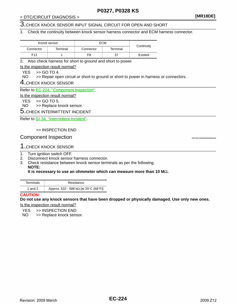
[MR18DE]P0327, P0328 KS
< DTC/CIRCUIT DIAGNOSIS >
3.CHECK KNOCK SENSOR INPUT SIGNAL CIRCUIT FOR OPEN AND SHORT
1. Check the continuity between knock sensor harness connector and ECM harness connector.
2. Also check harness for short to ground and short to power.Is the inspection result normal?YES >> GO TO 4.NO >> Repair open circuit or short to ground or short to power in harness or connectors.
4.CHECK KNOCK SENSOR
Refer to EC-224, "Component Inspection".Is the inspection result normal?YES >> GO TO 5.NO >> Replace knock sensor.
5.CHECK INTERMITTENT INCIDENT
Refer to GI-34, "Intermittent Incident".
>> INSPECTION END
Component Inspection INFOID:0000000004833334
1.CHECK KNOCK SENSOR
1. Turn ignition switch OFF.2. Disconnect knock sensor harness connector.3. Check resistance between knock sensor terminals as per the following.
NOTE:It is necessary to use an ohmmeter which can measure more than 10 MΩ.
CAUTION:Do not use any knock sensors that have been dropped or physically damaged. Use only new ones.Is the inspection result normal?YES >> INSPECTION ENDNO >> Replace knock sensor.
Knock sensor ECMContinuity
Connector Terminal Connector Terminal
F12 1 F8 37 Existed
Terminals Resistance
1 and 2 Approx. 532 - 588 kΩ [at 20°C (68°F)]
EC-224Revision: 2009 March 2009 Z12
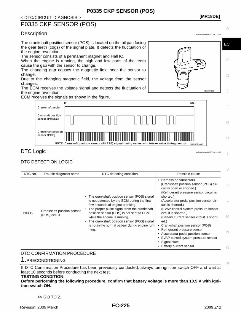
P0335 CKP SENSOR (POS)[MR18DE]
C
D
E
F
G
H
I
J
K
L
M
A
C
N
P
O
< DTC/CIRCUIT DIAGNOSIS >
E
P0335 CKP SENSOR (POS)
Description INFOID:0000000004833335
The crankshaft position sensor (POS) is located on the oil pan facingthe gear teeth (cogs) of the signal plate. It detects the fluctuation ofthe engine revolution.The sensor consists of a permanent magnet and Hall IC.When the engine is running, the high and low parts of the teethcause the gap with the sensor to change.The changing gap causes the magnetic field near the sensor tochange.Due to the changing magnetic field, the voltage from the sensorchanges.The ECM receives the voltage signal and detects the fluctuation ofthe engine revolution.ECM receives the signals as shown in the figure.
DTC Logic INFOID:0000000004833336
DTC DETECTION LOGIC
DTC CONFIRMATION PROCEDURE
1.PRECONDITIONING
If DTC Confirmation Procedure has been previously conducted, always turn ignition switch OFF and wait atleast 10 seconds before conducting the next test.TESTING CONDITION:Before performing the following procedure, confirm that battery voltage is more than 10.5 V with igni-tion switch ON.
>> GO TO 2.
PBIA9209J
JMBIA0714GB
DTC No. Trouble diagnosis name DTC detecting condition Possible cause
P0335Crankshaft position sensor (POS) circuit
• The crankshaft position sensor (POS) signal is not detected by the ECM during the first few seconds of engine cranking.
• The proper pulse signal from the crankshaft position sensor (POS) is not sent to ECM while the engine is running.
• The crankshaft position sensor (POS) signal is not in the normal pattern during engine run-ning.
• Harness or connectors[Crankshaft position sensor (POS) cir-cuit is open or shorted.](Refrigerant pressure sensor circuit is shorted.)(Accelerator pedal position sensor cir-cuit is shorted.)(EVAP control system pressure sensor circuit is shorted.)(Battery current sensor circuit is short-ed.)
• Crankshaft position sensor (POS)• Refrigerant pressure sensor• Accelerator pedal position sensor• EVAP control system pressure sensor• Signal plate• Battery current sensor
EC-225Revision: 2009 March 2009 Z12
[MR18DE]P0335 CKP SENSOR (POS)
< DTC/CIRCUIT DIAGNOSIS >
2.PERFORM DTC CONFIRMATION PROCEDURE
1. Start engine and let it idle for at least 5 seconds.If engine does not start, crank engine for at least 2 seconds.
2. Check 1st trip DTC.Is 1st trip DTC detected?YES >> Go to EC-226, "Diagnosis Procedure".NO >> INSPECTION END
Diagnosis Procedure INFOID:0000000004833338
1.CHECK GROUND CONNECTION
1. Turn ignition switch OFF.2. Check ground connection E38. Refer to GI-37, "Circuit Inspection".Is the inspection result normal?YES >> GO TO 2.NO >> Repair or replace ground connection.
2.CHECK CRANKSHAFT POSITION (CKP) SENSOR (POS) POWER SUPPLY CIRCUIT-I
1. Disconnect crankshaft position (CKP) sensor (POS) harness connector.2. Turn ignition switch ON.3. Check the voltage between CKP sensor (POS) harness connector and ground.
Is the inspection result normal?YES >> GO TO 8.NO >> GO TO 3.
3.CHECK CKP SENSOR (POS) POWER SUPPLY CIRCUIT-II
1. Turn ignition switch ON.2. Disconnect ECM harness connector.3. Check the continuity between CKP sensor (POS) harness connector and ECM harness connector.
Is the inspection result normal?YES >> GO TO 4.NO >> Repair open circuit.
4.CHECK CKP SENSOR POWER SUPPLY CIRCUIT
Check harness for short to power and short to ground, between the following terminals.
CKP sensor (POS)Ground Voltage
Connector Terminal
F20 1 Ground Approx. 5 V
CKP sensor (POS) ECMContinuity
Connector Terminal Connector Terminal
F20 1 F8 75 Existed
ECM Sensor
Connector Terminal Name Connector Terminal
F8
74 Refrigerant pressure sensor E49 3
75 CKP sensor (POS) F20 1
76EVAP control system pressure sen-sor
B21 3
77 Battery current sensor F51 1
E16 102 APP sensor E110 5
EC-226Revision: 2009 March 2009 Z12
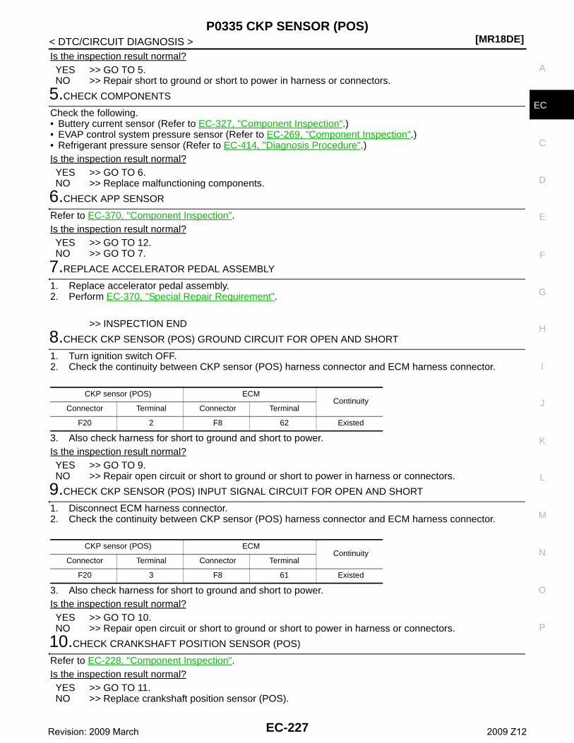
P0335 CKP SENSOR (POS)[MR18DE]
C
D
E
F
G
H
I
J
K
L
M
A
C
N
P
O
< DTC/CIRCUIT DIAGNOSIS >
E
Is the inspection result normal?YES >> GO TO 5.NO >> Repair short to ground or short to power in harness or connectors.
5.CHECK COMPONENTS
Check the following.• Buttery current sensor (Refer to EC-327, "Component Inspection".)• EVAP control system pressure sensor (Refer to EC-269, "Component Inspection".)• Refrigerant pressure sensor (Refer to EC-414, "Diagnosis Procedure".)Is the inspection result normal?YES >> GO TO 6.NO >> Replace malfunctioning components.
6.CHECK APP SENSOR
Refer to EC-370, "Component Inspection".Is the inspection result normal?YES >> GO TO 12.NO >> GO TO 7.
7.REPLACE ACCELERATOR PEDAL ASSEMBLY
1. Replace accelerator pedal assembly.2. Perform EC-370, "Special Repair Requirement".
>> INSPECTION END
8.CHECK CKP SENSOR (POS) GROUND CIRCUIT FOR OPEN AND SHORT
1. Turn ignition switch OFF.2. Check the continuity between CKP sensor (POS) harness connector and ECM harness connector.
3. Also check harness for short to ground and short to power.Is the inspection result normal?YES >> GO TO 9.NO >> Repair open circuit or short to ground or short to power in harness or connectors.
9.CHECK CKP SENSOR (POS) INPUT SIGNAL CIRCUIT FOR OPEN AND SHORT
1. Disconnect ECM harness connector.2. Check the continuity between CKP sensor (POS) harness connector and ECM harness connector.
3. Also check harness for short to ground and short to power.Is the inspection result normal?YES >> GO TO 10.NO >> Repair open circuit or short to ground or short to power in harness or connectors.
10.CHECK CRANKSHAFT POSITION SENSOR (POS)
Refer to EC-228, "Component Inspection".Is the inspection result normal?YES >> GO TO 11.NO >> Replace crankshaft position sensor (POS).
CKP sensor (POS) ECMContinuity
Connector Terminal Connector Terminal
F20 2 F8 62 Existed
CKP sensor (POS) ECMContinuity
Connector Terminal Connector Terminal
F20 3 F8 61 Existed
EC-227Revision: 2009 March 2009 Z12
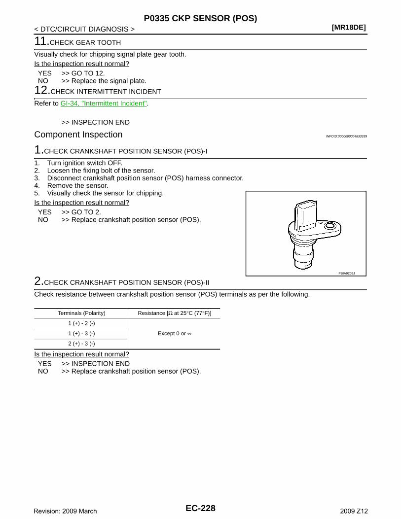
[MR18DE]P0335 CKP SENSOR (POS)
< DTC/CIRCUIT DIAGNOSIS >
11.CHECK GEAR TOOTH
Visually check for chipping signal plate gear tooth.Is the inspection result normal?YES >> GO TO 12.NO >> Replace the signal plate.
12.CHECK INTERMITTENT INCIDENT
Refer to GI-34, "Intermittent Incident".
>> INSPECTION END
Component Inspection INFOID:0000000004833339
1.CHECK CRANKSHAFT POSITION SENSOR (POS)-I
1. Turn ignition switch OFF.2. Loosen the fixing bolt of the sensor.3. Disconnect crankshaft position sensor (POS) harness connector.4. Remove the sensor.5. Visually check the sensor for chipping.Is the inspection result normal?YES >> GO TO 2.NO >> Replace crankshaft position sensor (POS).
2.CHECK CRANKSHAFT POSITION SENSOR (POS)-II
Check resistance between crankshaft position sensor (POS) terminals as per the following.
Is the inspection result normal?YES >> INSPECTION ENDNO >> Replace crankshaft position sensor (POS).
PBIA9209J
Terminals (Polarity) Resistance [Ω at 25°C (77°F)]
1 (+) - 2 (-)
Except 0 or ∞1 (+) - 3 (-)
2 (+) - 3 (-)
EC-228Revision: 2009 March 2009 Z12
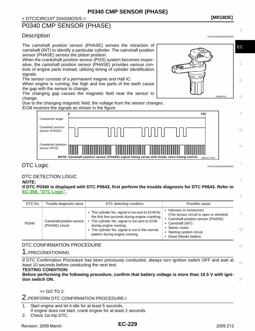
P0340 CMP SENSOR (PHASE)[MR18DE]
C
D
E
F
G
H
I
J
K
L
M
A
C
N
P
O
< DTC/CIRCUIT DIAGNOSIS >
E
P0340 CMP SENSOR (PHASE)
Description INFOID:0000000004833340
The camshaft position sensor (PHASE) senses the retraction ofcamshaft (INT) to identify a particular cylinder. The camshaft positionsensor (PHASE) senses the piston position.When the crankshaft position sensor (POS) system becomes inoper-ative, the camshaft position sensor (PHASE) provides various con-trols of engine parts instead, utilizing timing of cylinder identificationsignals.The sensor consists of a permanent magnet and Hall IC.When engine is running, the high and low parts of the teeth causethe gap with the sensor to change.The changing gap causes the magnetic field near the sensor tochange.Due to the changing magnetic field, the voltage from the sensor changes. ECM receives the signals as shown in the figure.
DTC Logic INFOID:0000000004833341
DTC DETECTION LOGICNOTE:If DTC P0340 is displayed with DTC P0643, first perform the trouble diagnosis for DTC P0643. Refer toEC-308, "DTC Logic".
DTC CONFIRMATION PROCEDURE
1.PRECONDITIONING
If DTC Confirmation Procedure has been previously conducted, always turn ignition switch OFF and wait atleast 10 seconds before conducting the next test.TESTING CONDITION:Before performing the following procedure, confirm that battery voltage is more than 10.5 V with igni-tion switch ON.
>> GO TO 2.
2.PERFORM DTC CONFIRMATION PROCEDURE-I
1. Start engine and let it idle for at least 5 seconds.If engine does not start, crank engine for at least 2 seconds.
2. Check 1st trip DTC.
PBIA9875J
JMBIA0714GB
DTC No. Trouble diagnosis name DTC detecting condition Possible cause
P0340Camshaft position sensor (PHASE) circuit
• The cylinder No. signal is not sent to ECM for the first few seconds during engine cranking.
• The cylinder No. signal is not sent to ECM during engine running.
• The cylinder No. signal is not in the normal pattern during engine running.
• Harness or connectors(The sensor circuit is open or shorted)
• Camshaft position sensor (PHASE)• Camshaft (INT)• Starter motor• Starting system circuit• Dead (Weak) battery
EC-229Revision: 2009 March 2009 Z12
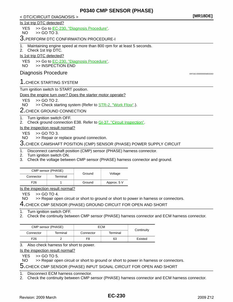
[MR18DE]P0340 CMP SENSOR (PHASE)
< DTC/CIRCUIT DIAGNOSIS >Is 1st trip DTC detected?YES >> Go to EC-230, "Diagnosis Procedure".NO >> GO TO 3.
3.PERFORM DTC CONFIRMATION PROCEDURE-I
1. Maintaining engine speed at more than 800 rpm for at least 5 seconds.2. Check 1st trip DTC.Is 1st trip DTC detected?YES >> Go to EC-230, "Diagnosis Procedure".NO >> INSPECTION END
Diagnosis Procedure INFOID:0000000004833343
1.CHECK STARTING SYSTEM
Turn ignition switch to START position.Does the engine turn over? Does the starter motor operate?YES >> GO TO 2.NO >> Check starting system (Refer to STR-2, "Work Flow".).
2.CHECK GROUND CONNECTION
1. Turn ignition switch OFF.2. Check ground connection E38. Refer to GI-37, "Circuit Inspection".Is the inspection result normal?YES >> GO TO 3.NO >> Repair or replace ground connection.
3.CHECK CAMSHAFT POSITION (CMP) SENSOR (PHASE) POWER SUPPLY CIRCUIT
1. Disconnect camshaft position (CMP) sensor (PHASE) harness connector.2. Turn ignition switch ON.3. Check the voltage between CMP sensor (PHASE) harness connector and ground.
Is the inspection result normal?YES >> GO TO 4.NO >> Repair open circuit or short to ground or short to power in harness or connectors.
4.CHECK CMP SENSOR (PHASE) GROUND CIRCUIT FOR OPEN AND SHORT
1. Turn ignition switch OFF.2. Check the continuity between CMP sensor (PHASE) harness connector and ECM harness connector.
3. Also check harness for short to power.Is the inspection result normal?YES >> GO TO 5.NO >> Repair open circuit or short to ground or short to power in harness or connectors.
5.CHECK CMP SENSOR (PHASE) INPUT SIGNAL CIRCUIT FOR OPEN AND SHORT
1. Disconnect ECM harness connector.2. Check the continuity between CMP sensor (PHASE) harness connector and ECM harness connector.
CMP sensor (PHASE)Ground Voltage
Connector Terminal
F26 1 Ground Approx. 5 V
CMP sensor (PHASE) ECMContinuity
Connector Terminal Connector Terminal
F26 2 F8 63 Existed
EC-230Revision: 2009 March 2009 Z12
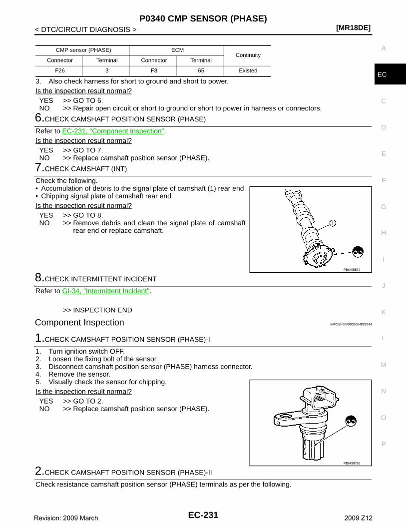
P0340 CMP SENSOR (PHASE)[MR18DE]
C
D
E
F
G
H
I
J
K
L
M
A
C
N
P
O
< DTC/CIRCUIT DIAGNOSIS >
E3. Also check harness for short to ground and short to power.Is the inspection result normal?YES >> GO TO 6.NO >> Repair open circuit or short to ground or short to power in harness or connectors.
6.CHECK CAMSHAFT POSITION SENSOR (PHASE)
Refer to EC-231, "Component Inspection".Is the inspection result normal?YES >> GO TO 7.NO >> Replace camshaft position sensor (PHASE).
7.CHECK CAMSHAFT (INT)
Check the following.• Accumulation of debris to the signal plate of camshaft (1) rear end• Chipping signal plate of camshaft rear endIs the inspection result normal?YES >> GO TO 8.NO >> Remove debris and clean the signal plate of camshaft
rear end or replace camshaft.
8.CHECK INTERMITTENT INCIDENT
Refer to GI-34, "Intermittent Incident".
>> INSPECTION END
Component Inspection INFOID:0000000004833344
1.CHECK CAMSHAFT POSITION SENSOR (PHASE)-I
1. Turn ignition switch OFF.2. Loosen the fixing bolt of the sensor.3. Disconnect camshaft position sensor (PHASE) harness connector.4. Remove the sensor.5. Visually check the sensor for chipping.Is the inspection result normal?YES >> GO TO 2.NO >> Replace camshaft position sensor (PHASE).
2.CHECK CAMSHAFT POSITION SENSOR (PHASE)-II
Check resistance camshaft position sensor (PHASE) terminals as per the following.
CMP sensor (PHASE) ECMContinuity
Connector Terminal Connector Terminal
F26 3 F8 65 Existed
PBIA9557J
PBIA9876J
EC-231Revision: 2009 March 2009 Z12
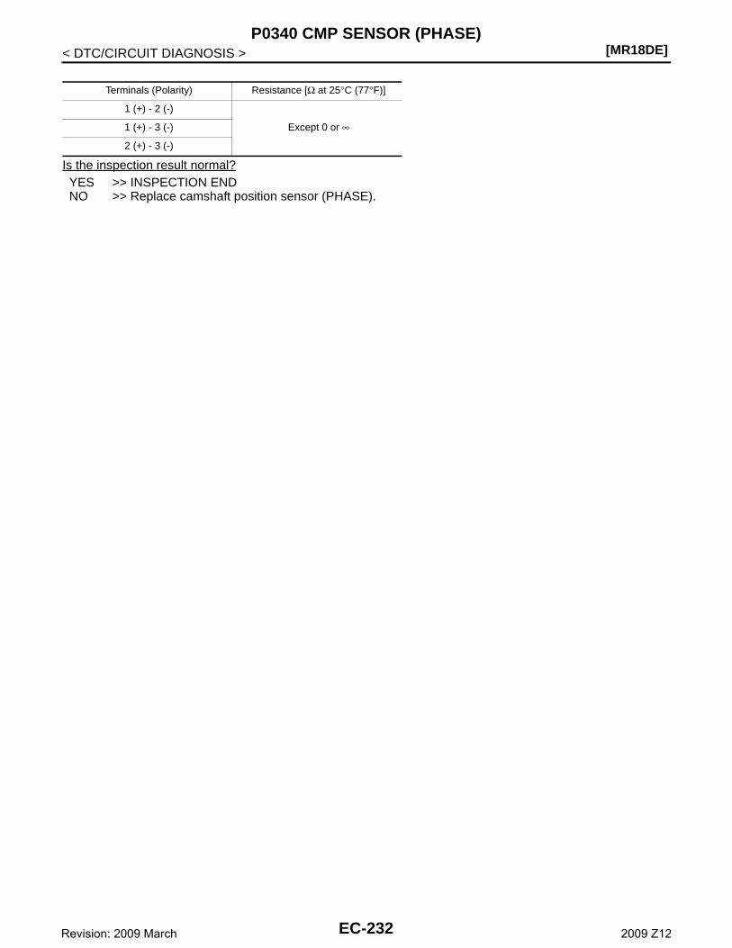
[MR18DE]P0340 CMP SENSOR (PHASE)
< DTC/CIRCUIT DIAGNOSIS >
Is the inspection result normal?YES >> INSPECTION ENDNO >> Replace camshaft position sensor (PHASE).
Terminals (Polarity) Resistance [Ω at 25°C (77°F)]
1 (+) - 2 (-)
Except 0 or ∞1 (+) - 3 (-)
2 (+) - 3 (-)
EC-232Revision: 2009 March 2009 Z12
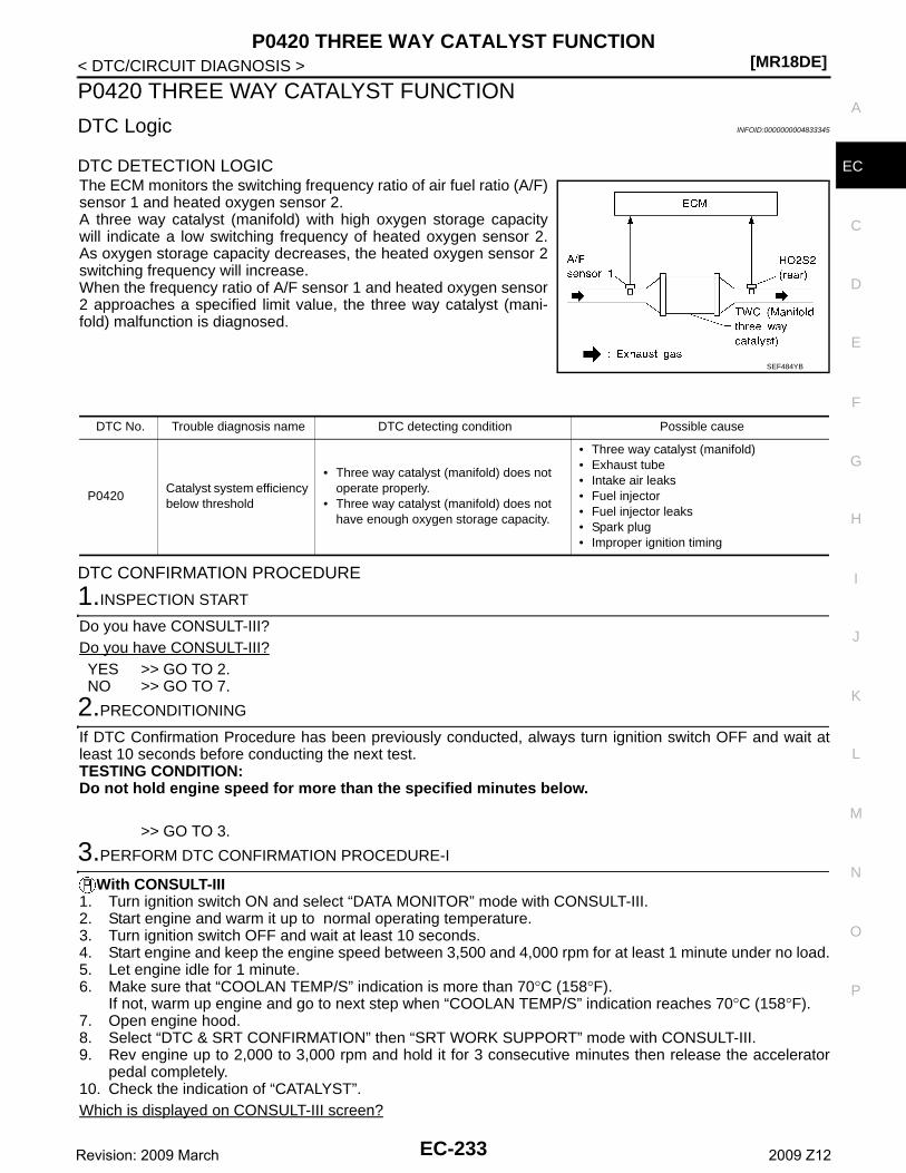
P0420 THREE WAY CATALYST FUNCTION[MR18DE]
C
D
E
F
G
H
I
J
K
L
M
A
C
N
P
O
< DTC/CIRCUIT DIAGNOSIS >
E
P0420 THREE WAY CATALYST FUNCTION
DTC Logic INFOID:0000000004833345
DTC DETECTION LOGICThe ECM monitors the switching frequency ratio of air fuel ratio (A/F)sensor 1 and heated oxygen sensor 2.A three way catalyst (manifold) with high oxygen storage capacitywill indicate a low switching frequency of heated oxygen sensor 2.As oxygen storage capacity decreases, the heated oxygen sensor 2switching frequency will increase.When the frequency ratio of A/F sensor 1 and heated oxygen sensor2 approaches a specified limit value, the three way catalyst (mani-fold) malfunction is diagnosed.
DTC CONFIRMATION PROCEDURE
1.INSPECTION START
Do you have CONSULT-III?Do you have CONSULT-III?YES >> GO TO 2.NO >> GO TO 7.
2.PRECONDITIONING
If DTC Confirmation Procedure has been previously conducted, always turn ignition switch OFF and wait atleast 10 seconds before conducting the next test.TESTING CONDITION:Do not hold engine speed for more than the specified minutes below.
>> GO TO 3.
3.PERFORM DTC CONFIRMATION PROCEDURE-I
With CONSULT-III1. Turn ignition switch ON and select “DATA MONITOR” mode with CONSULT-III.2. Start engine and warm it up to normal operating temperature.3. Turn ignition switch OFF and wait at least 10 seconds.4. Start engine and keep the engine speed between 3,500 and 4,000 rpm for at least 1 minute under no load.5. Let engine idle for 1 minute.6. Make sure that “COOLAN TEMP/S” indication is more than 70°C (158°F).
If not, warm up engine and go to next step when “COOLAN TEMP/S” indication reaches 70°C (158°F).7. Open engine hood.8. Select “DTC & SRT CONFIRMATION” then “SRT WORK SUPPORT” mode with CONSULT-III.9. Rev engine up to 2,000 to 3,000 rpm and hold it for 3 consecutive minutes then release the accelerator
pedal completely.10. Check the indication of “CATALYST”.Which is displayed on CONSULT-III screen?
SEF484YB
DTC No. Trouble diagnosis name DTC detecting condition Possible cause
P0420Catalyst system efficiency below threshold
• Three way catalyst (manifold) does not operate properly.
• Three way catalyst (manifold) does not have enough oxygen storage capacity.
• Three way catalyst (manifold)• Exhaust tube• Intake air leaks• Fuel injector• Fuel injector leaks• Spark plug• Improper ignition timing
EC-233Revision: 2009 March 2009 Z12
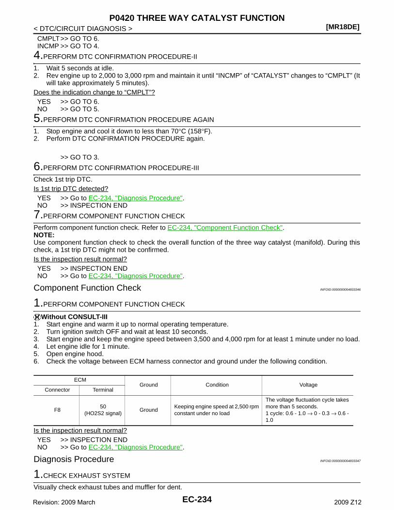
[MR18DE]P0420 THREE WAY CATALYST FUNCTION
< DTC/CIRCUIT DIAGNOSIS >CMPLT>> GO TO 6.INCMP >> GO TO 4.
4.PERFORM DTC CONFIRMATION PROCEDURE-II
1. Wait 5 seconds at idle.2. Rev engine up to 2,000 to 3,000 rpm and maintain it until “INCMP” of “CATALYST” changes to “CMPLT” (It
will take approximately 5 minutes).Does the indication change to “CMPLT”?YES >> GO TO 6.NO >> GO TO 5.
5.PERFORM DTC CONFIRMATION PROCEDURE AGAIN
1. Stop engine and cool it down to less than 70°C (158°F).2. Perform DTC CONFIRMATION PROCEDURE again.
>> GO TO 3.
6.PERFORM DTC CONFIRMATION PROCEDURE-III
Check 1st trip DTC.Is 1st trip DTC detected?YES >> Go to EC-234, "Diagnosis Procedure".NO >> INSPECTION END
7.PERFORM COMPONENT FUNCTION CHECK
Perform component function check. Refer to EC-234, "Component Function Check".NOTE:Use component function check to check the overall function of the three way catalyst (manifold). During thischeck, a 1st trip DTC might not be confirmed.Is the inspection result normal?YES >> INSPECTION ENDNO >> Go to EC-234, "Diagnosis Procedure".
Component Function Check INFOID:0000000004833346
1.PERFORM COMPONENT FUNCTION CHECK
Without CONSULT-III1. Start engine and warm it up to normal operating temperature.2. Turn ignition switch OFF and wait at least 10 seconds.3. Start engine and keep the engine speed between 3,500 and 4,000 rpm for at least 1 minute under no load.4. Let engine idle for 1 minute.5. Open engine hood.6. Check the voltage between ECM harness connector and ground under the following condition.
Is the inspection result normal?YES >> INSPECTION ENDNO >> Go to EC-234, "Diagnosis Procedure".
Diagnosis Procedure INFOID:0000000004833347
1.CHECK EXHAUST SYSTEM
Visually check exhaust tubes and muffler for dent.
ECMGround Condition Voltage
Connector Terminal
F850
(HO2S2 signal)Ground
Keeping engine speed at 2,500 rpm constant under no load
The voltage fluctuation cycle takes more than 5 seconds.1 cycle: 0.6 - 1.0 → 0 - 0.3 → 0.6 - 1.0
EC-234Revision: 2009 March 2009 Z12
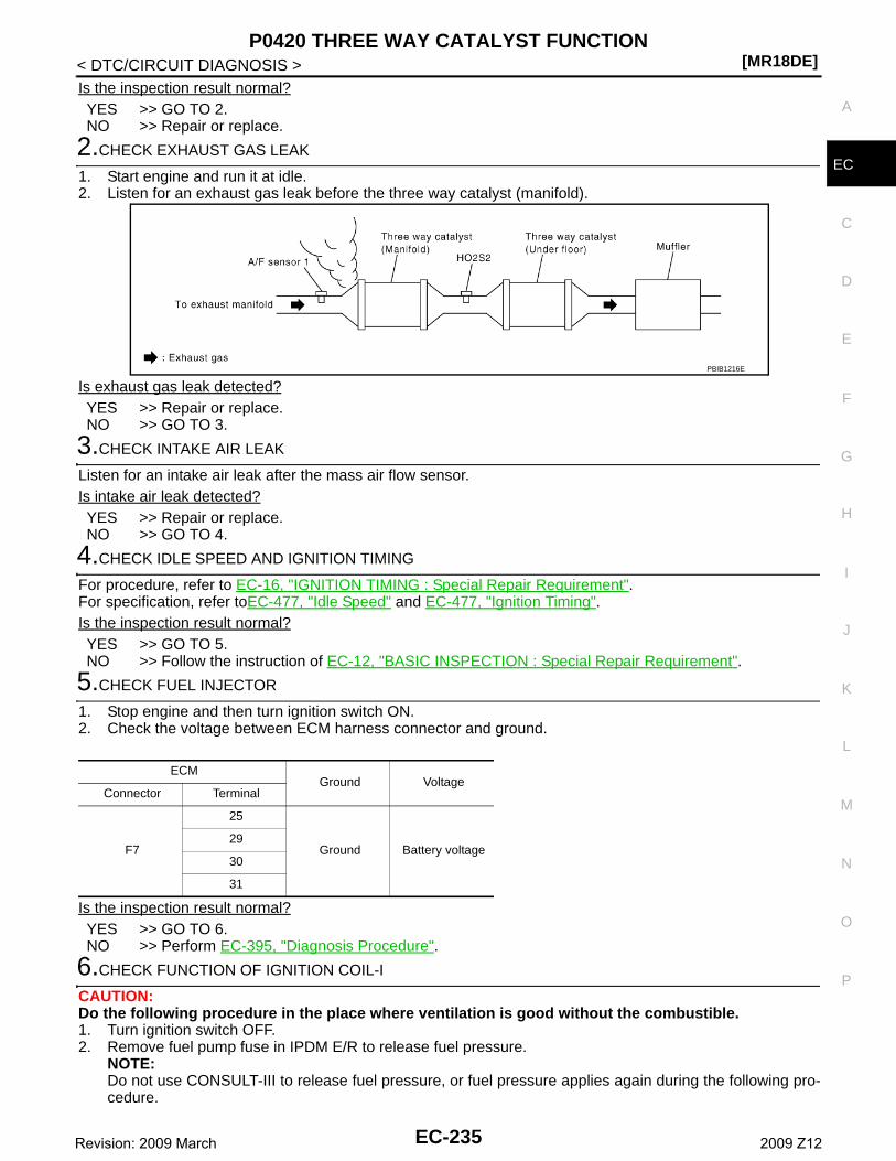
P0420 THREE WAY CATALYST FUNCTION[MR18DE]
C
D
E
F
G
H
I
J
K
L
M
A
C
N
P
O
< DTC/CIRCUIT DIAGNOSIS >
E
Is the inspection result normal?YES >> GO TO 2.NO >> Repair or replace.
2.CHECK EXHAUST GAS LEAK
1. Start engine and run it at idle.2. Listen for an exhaust gas leak before the three way catalyst (manifold).
Is exhaust gas leak detected?YES >> Repair or replace.NO >> GO TO 3.
3.CHECK INTAKE AIR LEAK
Listen for an intake air leak after the mass air flow sensor.Is intake air leak detected?YES >> Repair or replace.NO >> GO TO 4.
4.CHECK IDLE SPEED AND IGNITION TIMING
For procedure, refer to EC-16, "IGNITION TIMING : Special Repair Requirement".For specification, refer toEC-477, "Idle Speed" and EC-477, "Ignition Timing".Is the inspection result normal?YES >> GO TO 5.NO >> Follow the instruction of EC-12, "BASIC INSPECTION : Special Repair Requirement".
5.CHECK FUEL INJECTOR
1. Stop engine and then turn ignition switch ON.2. Check the voltage between ECM harness connector and ground.
Is the inspection result normal?YES >> GO TO 6.NO >> Perform EC-395, "Diagnosis Procedure".
6.CHECK FUNCTION OF IGNITION COIL-I
CAUTION:Do the following procedure in the place where ventilation is good without the combustible.1. Turn ignition switch OFF.2. Remove fuel pump fuse in IPDM E/R to release fuel pressure.
NOTE:Do not use CONSULT-III to release fuel pressure, or fuel pressure applies again during the following pro-cedure.
PBIB1216E
ECMGround Voltage
Connector Terminal
F7
25
Ground Battery voltage29
30
31
EC-235Revision: 2009 March 2009 Z12
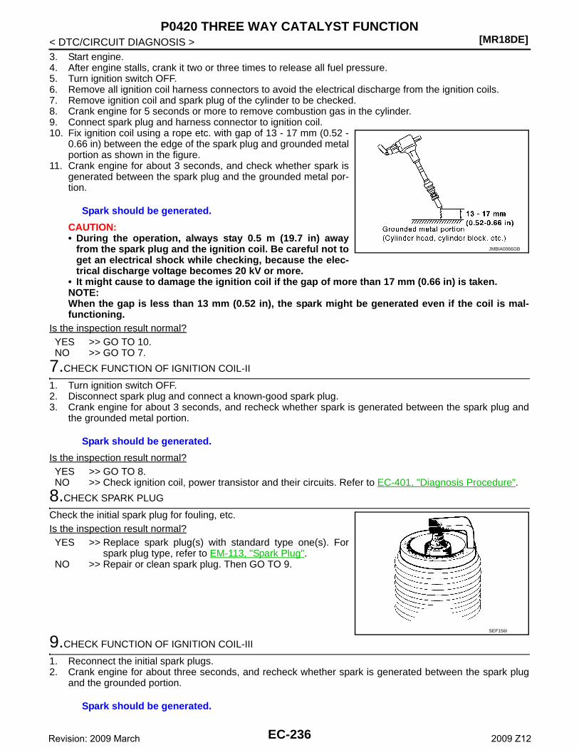
[MR18DE]P0420 THREE WAY CATALYST FUNCTION
< DTC/CIRCUIT DIAGNOSIS >3. Start engine.4. After engine stalls, crank it two or three times to release all fuel pressure.5. Turn ignition switch OFF.6. Remove all ignition coil harness connectors to avoid the electrical discharge from the ignition coils.7. Remove ignition coil and spark plug of the cylinder to be checked.8. Crank engine for 5 seconds or more to remove combustion gas in the cylinder.9. Connect spark plug and harness connector to ignition coil.10. Fix ignition coil using a rope etc. with gap of 13 - 17 mm (0.52 -
0.66 in) between the edge of the spark plug and grounded metalportion as shown in the figure.
11. Crank engine for about 3 seconds, and check whether spark isgenerated between the spark plug and the grounded metal por-tion.
CAUTION:• During the operation, always stay 0.5 m (19.7 in) away
from the spark plug and the ignition coil. Be careful not toget an electrical shock while checking, because the elec-trical discharge voltage becomes 20 kV or more.
• It might cause to damage the ignition coil if the gap of more than 17 mm (0.66 in) is taken.NOTE:When the gap is less than 13 mm (0.52 in), the spark might be generated even if the coil is mal-functioning.
Is the inspection result normal?YES >> GO TO 10.NO >> GO TO 7.
7.CHECK FUNCTION OF IGNITION COIL-II
1. Turn ignition switch OFF.2. Disconnect spark plug and connect a known-good spark plug.3. Crank engine for about 3 seconds, and recheck whether spark is generated between the spark plug and
the grounded metal portion.
Is the inspection result normal?YES >> GO TO 8.NO >> Check ignition coil, power transistor and their circuits. Refer to EC-401, "Diagnosis Procedure".
8.CHECK SPARK PLUG
Check the initial spark plug for fouling, etc.Is the inspection result normal?YES >> Replace spark plug(s) with standard type one(s). For
spark plug type, refer to EM-113, "Spark Plug".NO >> Repair or clean spark plug. Then GO TO 9.
9.CHECK FUNCTION OF IGNITION COIL-III
1. Reconnect the initial spark plugs.2. Crank engine for about three seconds, and recheck whether spark is generated between the spark plug
and the grounded portion.
Spark should be generated.
JMBIA0066GB
Spark should be generated.
SEF156I
Spark should be generated.
EC-236Revision: 2009 March 2009 Z12
P0420 THREE WAY CATALYST FUNCTION[MR18DE]
C
D
E
F
G
H
I
J
K
L
M
A
C
N
P
O
< DTC/CIRCUIT DIAGNOSIS >
E
Is the inspection result normal?YES >> INSPECTION ENDNO >> Replace spark plug(s) with standard type one(s). For spark plug type, refer to EM-113, "Spark
Plug".
10.CHECK FUEL INJECTOR
1. Turn ignition switch OFF. Refer to EM-35, "Removal and Installation".2. Remove fuel injector assembly.
Keep fuel hose and all fuel injectors connected to fuel tube.3. Disconnect all ignition coil harness connectors.4. Reconnect all fuel injector harness connectors disconnected.5. Turn ignition switch ON.Does fuel drip from fuel injector?YES >> GO TO 11.NO >> Replace the fuel injector(s) from which fuel is dripping.
11.CHECK INTERMITTENT INCIDENT
Refer to GI-34, "Intermittent Incident".Is the inspection result normal?YES >> Replace three way catalyst assembly.NO >> Repair or replace harness or connector
EC-237Revision: 2009 March 2009 Z12
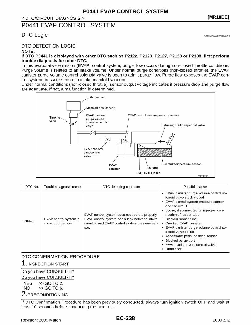
[MR18DE]P0441 EVAP CONTROL SYSTEM
< DTC/CIRCUIT DIAGNOSIS >
P0441 EVAP CONTROL SYSTEM
DTC Logic INFOID:0000000004833348
DTC DETECTION LOGICNOTE:If DTC P0441 is displayed with other DTC such as P2122, P2123, P2127, P2128 or P2138, first performtrouble diagnosis for other DTC.In this evaporative emission (EVAP) control system, purge flow occurs during non-closed throttle conditions.Purge volume is related to air intake volume. Under normal purge conditions (non-closed throttle), the EVAPcanister purge volume control solenoid valve is open to admit purge flow. Purge flow exposes the EVAP con-trol system pressure sensor to intake manifold vacuum.Under normal conditions (non-closed throttle), sensor output voltage indicates if pressure drop and purge floware adequate. If not, a malfunction is determined.
DTC CONFIRMATION PROCEDURE
1.INSPECTION START
Do you have CONSULT-III?Do you have CONSULT-III?YES >> GO TO 2.NO >> GO TO 6.
2.PRECONDITIONING
If DTC Confirmation Procedure has been previously conducted, always turn ignition switch OFF and wait atleast 10 seconds before conducting the next test.
PBIB1026E
DTC No. Trouble diagnosis name DTC detecting condition Possible cause
P0441EVAP control system in-correct purge flow
EVAP control system does not operate properly, EVAP control system has a leak between intake manifold and EVAP control system pressure sen-sor.
• EVAP canister purge volume control so-lenoid valve stuck closed
• EVAP control system pressure sensor and the circuit
• Loose, disconnected or improper con-nection of rubber tube
• Blocked rubber tube• Cracked EVAP canister• EVAP canister purge volume control so-
lenoid valve circuit• Accelerator pedal position sensor• Blocked purge port• EVAP canister vent control valve• Drain filter
EC-238Revision: 2009 March 2009 Z12
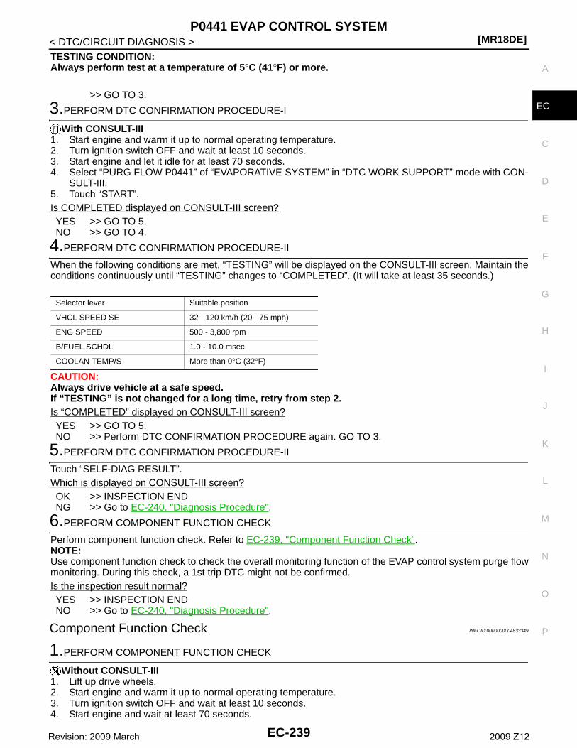
P0441 EVAP CONTROL SYSTEM[MR18DE]
C
D
E
F
G
H
I
J
K
L
M
A
C
N
P
O
< DTC/CIRCUIT DIAGNOSIS >
E
TESTING CONDITION:Always perform test at a temperature of 5°C (41°F) or more.
>> GO TO 3.
3.PERFORM DTC CONFIRMATION PROCEDURE-I
With CONSULT-III1. Start engine and warm it up to normal operating temperature.2. Turn ignition switch OFF and wait at least 10 seconds.3. Start engine and let it idle for at least 70 seconds.4. Select “PURG FLOW P0441” of “EVAPORATIVE SYSTEM” in “DTC WORK SUPPORT” mode with CON-
SULT-III.5. Touch “START”.Is COMPLETED displayed on CONSULT-III screen?YES >> GO TO 5.NO >> GO TO 4.
4.PERFORM DTC CONFIRMATION PROCEDURE-II
When the following conditions are met, “TESTING” will be displayed on the CONSULT-III screen. Maintain theconditions continuously until “TESTING” changes to “COMPLETED”. (It will take at least 35 seconds.)
CAUTION:Always drive vehicle at a safe speed.If “TESTING” is not changed for a long time, retry from step 2.Is “COMPLETED” displayed on CONSULT-III screen?YES >> GO TO 5.NO >> Perform DTC CONFIRMATION PROCEDURE again. GO TO 3.
5.PERFORM DTC CONFIRMATION PROCEDURE-II
Touch “SELF-DIAG RESULT”.Which is displayed on CONSULT-III screen?OK >> INSPECTION ENDNG >> Go to EC-240, "Diagnosis Procedure".
6.PERFORM COMPONENT FUNCTION CHECK
Perform component function check. Refer to EC-239, "Component Function Check".NOTE:Use component function check to check the overall monitoring function of the EVAP control system purge flowmonitoring. During this check, a 1st trip DTC might not be confirmed.Is the inspection result normal?YES >> INSPECTION ENDNO >> Go to EC-240, "Diagnosis Procedure".
Component Function Check INFOID:0000000004833349
1.PERFORM COMPONENT FUNCTION CHECK
Without CONSULT-III1. Lift up drive wheels.2. Start engine and warm it up to normal operating temperature.3. Turn ignition switch OFF and wait at least 10 seconds.4. Start engine and wait at least 70 seconds.
Selector lever Suitable position
VHCL SPEED SE 32 - 120 km/h (20 - 75 mph)
ENG SPEED 500 - 3,800 rpm
B/FUEL SCHDL 1.0 - 10.0 msec
COOLAN TEMP/S More than 0°C (32°F)
EC-239Revision: 2009 March 2009 Z12
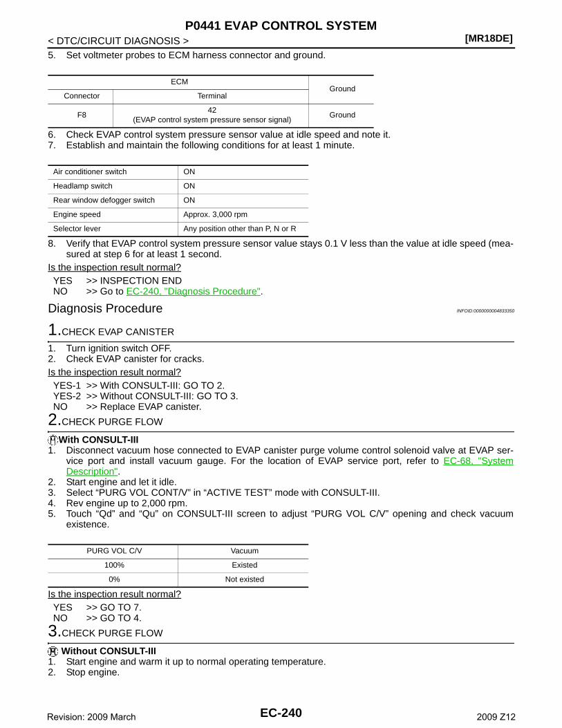
[MR18DE]P0441 EVAP CONTROL SYSTEM
< DTC/CIRCUIT DIAGNOSIS >5. Set voltmeter probes to ECM harness connector and ground.
6. Check EVAP control system pressure sensor value at idle speed and note it.7. Establish and maintain the following conditions for at least 1 minute.
8. Verify that EVAP control system pressure sensor value stays 0.1 V less than the value at idle speed (mea-sured at step 6 for at least 1 second.
Is the inspection result normal?YES >> INSPECTION ENDNO >> Go to EC-240, "Diagnosis Procedure".
Diagnosis Procedure INFOID:0000000004833350
1.CHECK EVAP CANISTER
1. Turn ignition switch OFF.2. Check EVAP canister for cracks.Is the inspection result normal?YES-1 >> With CONSULT-III: GO TO 2.YES-2 >> Without CONSULT-III: GO TO 3.NO >> Replace EVAP canister.
2.CHECK PURGE FLOW
With CONSULT-III1. Disconnect vacuum hose connected to EVAP canister purge volume control solenoid valve at EVAP ser-
vice port and install vacuum gauge. For the location of EVAP service port, refer to EC-68, "SystemDescription".
2. Start engine and let it idle.3. Select “PURG VOL CONT/V” in “ACTIVE TEST” mode with CONSULT-III.4. Rev engine up to 2,000 rpm.5. Touch “Qd” and “Qu” on CONSULT-III screen to adjust “PURG VOL C/V” opening and check vacuum
existence.
Is the inspection result normal?YES >> GO TO 7.NO >> GO TO 4.
3.CHECK PURGE FLOW
Without CONSULT-III1. Start engine and warm it up to normal operating temperature.2. Stop engine.
ECMGround
Connector Terminal
F842
(EVAP control system pressure sensor signal)Ground
Air conditioner switch ON
Headlamp switch ON
Rear window defogger switch ON
Engine speed Approx. 3,000 rpm
Selector lever Any position other than P, N or R
PURG VOL C/V Vacuum
100% Existed
0% Not existed
EC-240Revision: 2009 March 2009 Z12
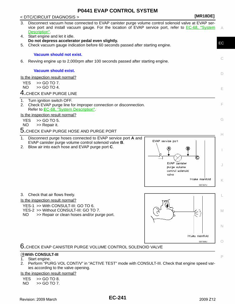
P0441 EVAP CONTROL SYSTEM[MR18DE]
C
D
E
F
G
H
I
J
K
L
M
A
C
N
P
O
< DTC/CIRCUIT DIAGNOSIS >
E
3. Disconnect vacuum hose connected to EVAP canister purge volume control solenoid valve at EVAP ser-vice port and install vacuum gauge. For the location of EVAP service port, refer to EC-68, "SystemDescription".
4. Start engine and let it idle.Do not depress accelerator pedal even slightly.
5. Check vacuum gauge indication before 60 seconds passed after starting engine.
6. Revving engine up to 2,000rpm after 100 seconds passed after starting engine.
Is the inspection result normal?YES >> GO TO 7.NO >> GO TO 4.
4.CHECK EVAP PURGE LINE
1. Turn ignition switch OFF.2. Check EVAP purge line for improper connection or disconnection.
Refer to EC-68, "System Description".Is the inspection result normal?YES >> GO TO 5.NO >> Repair it.
5.CHECK EVAP PURGE HOSE AND PURGE PORT
1. Disconnect purge hoses connected to EVAP service port A andEVAP canister purge volume control solenoid valve B.
2. Blow air into each hose and EVAP purge port C.
3. Check that air flows freely.Is the inspection result normal?YES-1 >> With CONSULT-III: GO TO 6.YES-2 >> Without CONSULT-III: GO TO 7.NO >> Repair or clean hoses and/or purge port.
6.CHECK EVAP CANISTER PURGE VOLUME CONTROL SOLENOID VALVE
With CONSULT-III1. Start engine.2. Perform “PURG VOL CONT/V” in “ACTIVE TEST” mode with CONSULT-III. Check that engine speed var-
ies according to the valve opening.Is the inspection result normal?YES >> GO TO 8.NO >> GO TO 7.
Vacuum should not exist.
Vacuum should exist.
SEF367U
SEF368U
EC-241Revision: 2009 March 2009 Z12
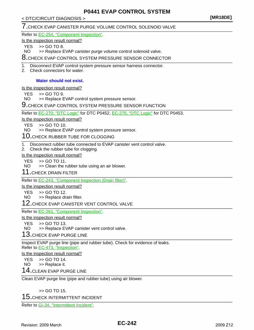
[MR18DE]P0441 EVAP CONTROL SYSTEM
< DTC/CIRCUIT DIAGNOSIS >
7.CHECK EVAP CANISTER PURGE VOLUME CONTROL SOLENOID VALVE
Refer to EC-254, "Component Inspection".Is the inspection result normal?YES >> GO TO 8.NO >> Replace EVAP canister purge volume control solenoid valve.
8.CHECK EVAP CONTROL SYSTEM PRESSURE SENSOR CONNECTOR
1. Disconnect EVAP control system pressure sensor harness connector.2. Check connectors for water.
Is the inspection result normal?YES >> GO TO 9.NO >> Replace EVAP control system pressure sensor.
9.CHECK EVAP CONTROL SYSTEM PRESSURE SENSOR FUNCTION
Refer to EC-270, "DTC Logic" for DTC P0452, EC-275, "DTC Logic" for DTC P0453.Is the inspection result normal?YES >> GO TO 10.NO >> Replace EVAP control system pressure sensor.
10.CHECK RUBBER TUBE FOR CLOGGING
1. Disconnect rubber tube connected to EVAP canister vent control valve.2. Check the rubber tube for clogging.Is the inspection result normal?YES >> GO TO 11.NO >> Clean the rubber tube using an air blower.
11.CHECK DRAIN FILTER
Refer to EC-243, "Component Inspection (Drain filter)".Is the inspection result normal?YES >> GO TO 12.NO >> Replace drain filter.
12.CHECK EVAP CANISTER VENT CONTROL VALVE
Refer to EC-261, "Component Inspection".Is the inspection result normal?YES >> GO TO 13.NO >> Replace EVAP canister vent control valve.
13.CHECK EVAP PURGE LINE
Inspect EVAP purge line (pipe and rubber tube). Check for evidence of leaks.Refer to EC-473, "Inspection".Is the inspection result normal?YES >> GO TO 14.NO >> Replace it.
14.CLEAN EVAP PURGE LINE
Clean EVAP purge line (pipe and rubber tube) using air blower.
>> GO TO 15.
15.CHECK INTERMITTENT INCIDENT
Refer to GI-34, "Intermittent Incident".
Water should not exist.
EC-242Revision: 2009 March 2009 Z12
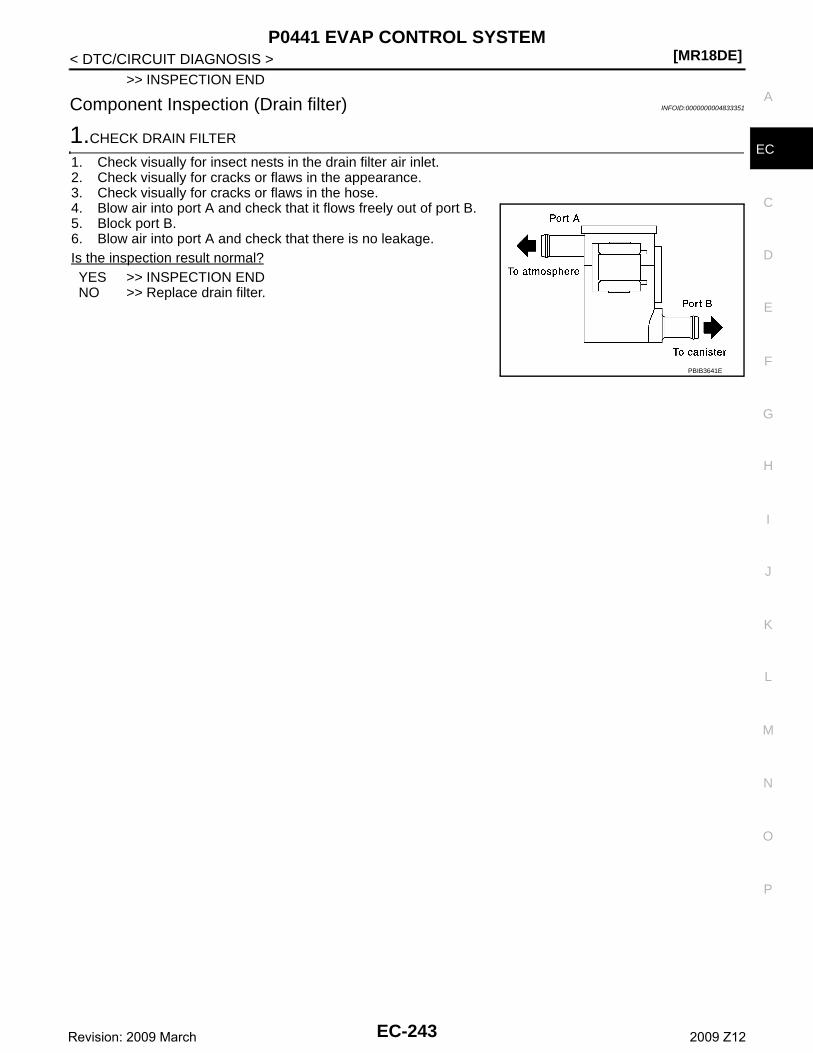
P0441 EVAP CONTROL SYSTEM[MR18DE]
C
D
E
F
G
H
I
J
K
L
M
A
C
N
P
O
< DTC/CIRCUIT DIAGNOSIS >
E
>> INSPECTION END
Component Inspection (Drain filter) INFOID:0000000004833351
1.CHECK DRAIN FILTER
1. Check visually for insect nests in the drain filter air inlet.2. Check visually for cracks or flaws in the appearance.3. Check visually for cracks or flaws in the hose.4. Blow air into port A and check that it flows freely out of port B.5. Block port B.6. Blow air into port A and check that there is no leakage.Is the inspection result normal?YES >> INSPECTION ENDNO >> Replace drain filter.
PBIB3641E
EC-243Revision: 2009 March 2009 Z12
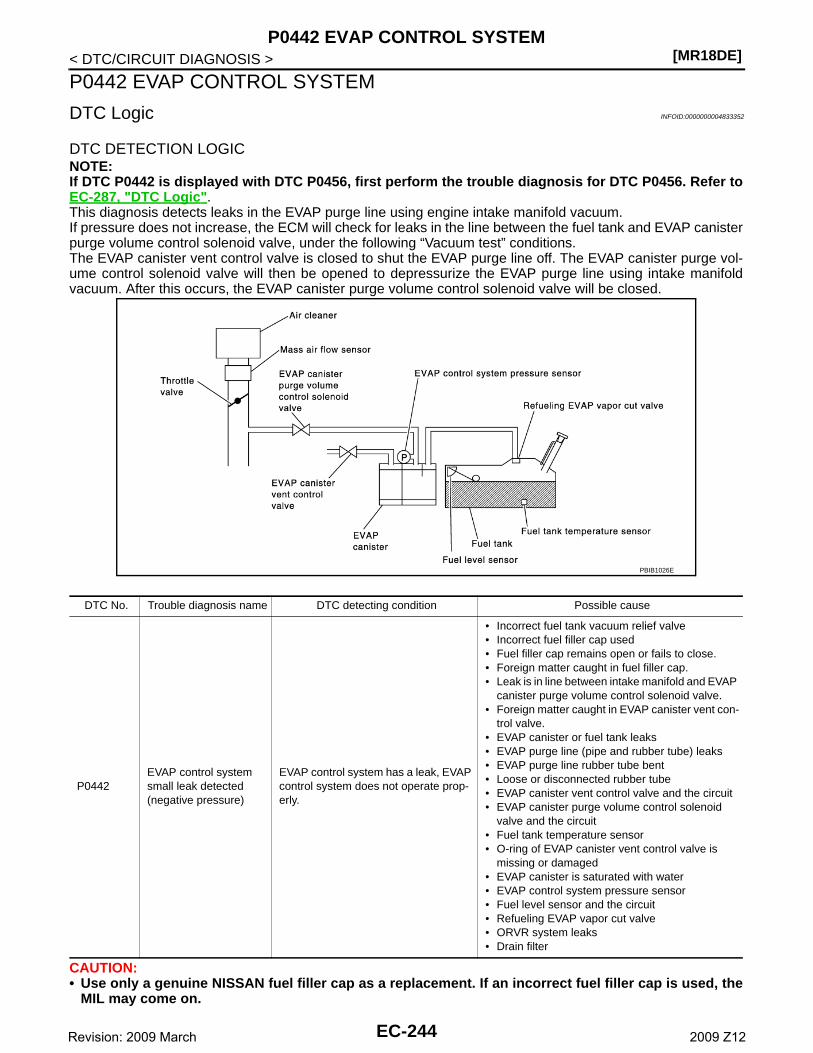
[MR18DE]P0442 EVAP CONTROL SYSTEM
< DTC/CIRCUIT DIAGNOSIS >
P0442 EVAP CONTROL SYSTEM
DTC Logic INFOID:0000000004833352
DTC DETECTION LOGICNOTE:If DTC P0442 is displayed with DTC P0456, first perform the trouble diagnosis for DTC P0456. Refer toEC-287, "DTC Logic".This diagnosis detects leaks in the EVAP purge line using engine intake manifold vacuum.If pressure does not increase, the ECM will check for leaks in the line between the fuel tank and EVAP canisterpurge volume control solenoid valve, under the following “Vacuum test” conditions.The EVAP canister vent control valve is closed to shut the EVAP purge line off. The EVAP canister purge vol-ume control solenoid valve will then be opened to depressurize the EVAP purge line using intake manifoldvacuum. After this occurs, the EVAP canister purge volume control solenoid valve will be closed.
CAUTION:• Use only a genuine NISSAN fuel filler cap as a replacement. If an incorrect fuel filler cap is used, the
MIL may come on.
DTC No. Trouble diagnosis name DTC detecting condition Possible cause
P0442EVAP control system small leak detected (negative pressure)
EVAP control system has a leak, EVAP control system does not operate prop-erly.
• Incorrect fuel tank vacuum relief valve• Incorrect fuel filler cap used• Fuel filler cap remains open or fails to close.• Foreign matter caught in fuel filler cap.• Leak is in line between intake manifold and EVAP
canister purge volume control solenoid valve.• Foreign matter caught in EVAP canister vent con-
trol valve.• EVAP canister or fuel tank leaks• EVAP purge line (pipe and rubber tube) leaks• EVAP purge line rubber tube bent• Loose or disconnected rubber tube• EVAP canister vent control valve and the circuit• EVAP canister purge volume control solenoid
valve and the circuit• Fuel tank temperature sensor• O-ring of EVAP canister vent control valve is
missing or damaged• EVAP canister is saturated with water• EVAP control system pressure sensor• Fuel level sensor and the circuit• Refueling EVAP vapor cut valve• ORVR system leaks• Drain filter
PBIB1026E
EC-244Revision: 2009 March 2009 Z12
P0442 EVAP CONTROL SYSTEM[MR18DE]
C
D
E
F
G
H
I
J
K
L
M
A
C
N
P
O
< DTC/CIRCUIT DIAGNOSIS >
E
• If the fuel filler cap is not tightened properly, the MIL may come on.• Use only a genuine NISSAN rubber tube as a replacement.
DTC CONFIRMATION PROCEDURE
1.PRECONDITIONING
If DTC Confirmation Procedure has been previously conducted, always turn ignition switch OFF and wait atleast 10 seconds before conducting the next test.TESTING CONDITION:• Perform “DTC WORK SUPPORT” when the fuel level is between 1/4 and 3/4 full, and vehicle is placed
on flat level surface.• Always perform test at a temperature of 0 to 30°C (32 to 86°F).NOTE:Make sure that EVAP hoses are connected to EVAP canister purge volume control solenoid valveproperly.Do you have CONSULT-III?YES >> GO TO 2.NO >> GO TO 3.
2.PERFORM DTC CONFIRMATION PROCEDURE
With CONSULT-III1. Turn ignition switch ON.2. Turn ignition switch OFF and wait at least 10 seconds.3. Turn ignition switch ON and select “DATA MONITOR” mode with CONSULT-III.4. Make sure that the following conditions are met.
COOLAN TEMP/S: 0 - 70°C (32 - 158°F)INT/A TEMP SE: 0 - 30°C (32 - 86°F)
5. Select “EVAP SML LEAK P0442/P1442” of “EVAPORATIVE SYSTEM” in “DTC WORK SUPPORT” modewith CONSULT-III.Follow the instruction displayed.NOTE:If the engine speed cannot be maintained within the range displayed on the CONSULT-III screen, go toEC-12, "BASIC INSPECTION : Special Repair Requirement".
Which is displayed on CONSULT-III screen?OK >> INSPECTION ENDNG >> Go to EC-245, "Diagnosis Procedure".
3.PERFORM COMPONENT FUNCTION CHECK
With GSTNOTE:Be sure to read the explanation of DRIVING PATTERN in EC-451, "How to Set SRT Code" before drivingvehicle.1. Start engine.2. Drive vehicle according to DRIVING PATTERN.3. Stop vehicle.4. Turn ignition switch OFF, wait at least 10 seconds and then turn ON.5. Select Service $07 with GST.Is 1st trip DTC displayed?YES-1 >> P0441: Go to EC-240, "Diagnosis Procedure".YES-2 >> P0442: Go to EC-245, "Diagnosis Procedure".NO >> INSPECTION END
Diagnosis Procedure INFOID:0000000004833353
1.CHECK FUEL FILLER CAP DESIGN
1. Turn ignition switch OFF.
EC-245Revision: 2009 March 2009 Z12
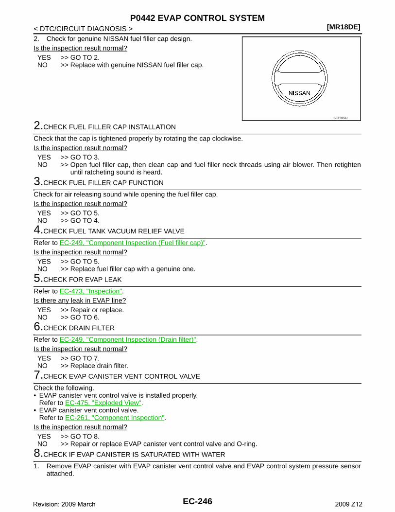
[MR18DE]P0442 EVAP CONTROL SYSTEM
< DTC/CIRCUIT DIAGNOSIS >2. Check for genuine NISSAN fuel filler cap design.Is the inspection result normal?YES >> GO TO 2.NO >> Replace with genuine NISSAN fuel filler cap.
2.CHECK FUEL FILLER CAP INSTALLATION
Check that the cap is tightened properly by rotating the cap clockwise.Is the inspection result normal?YES >> GO TO 3.NO >> Open fuel filler cap, then clean cap and fuel filler neck threads using air blower. Then retighten
until ratcheting sound is heard.
3.CHECK FUEL FILLER CAP FUNCTION
Check for air releasing sound while opening the fuel filler cap.Is the inspection result normal?YES >> GO TO 5.NO >> GO TO 4.
4.CHECK FUEL TANK VACUUM RELIEF VALVE
Refer to EC-249, "Component Inspection (Fuel filler cap)".Is the inspection result normal?YES >> GO TO 5.NO >> Replace fuel filler cap with a genuine one.
5.CHECK FOR EVAP LEAK
Refer to EC-473, "Inspection".Is there any leak in EVAP line?YES >> Repair or replace.NO >> GO TO 6.
6.CHECK DRAIN FILTER
Refer to EC-249, "Component Inspection (Drain filter)".Is the inspection result normal?YES >> GO TO 7.NO >> Replace drain filter.
7.CHECK EVAP CANISTER VENT CONTROL VALVE
Check the following.• EVAP canister vent control valve is installed properly.
Refer to EC-475, "Exploded View".• EVAP canister vent control valve.
Refer to EC-261, "Component Inspection".Is the inspection result normal?YES >> GO TO 8.NO >> Repair or replace EVAP canister vent control valve and O-ring.
8.CHECK IF EVAP CANISTER IS SATURATED WITH WATER
1. Remove EVAP canister with EVAP canister vent control valve and EVAP control system pressure sensorattached.
SEF915U
EC-246Revision: 2009 March 2009 Z12
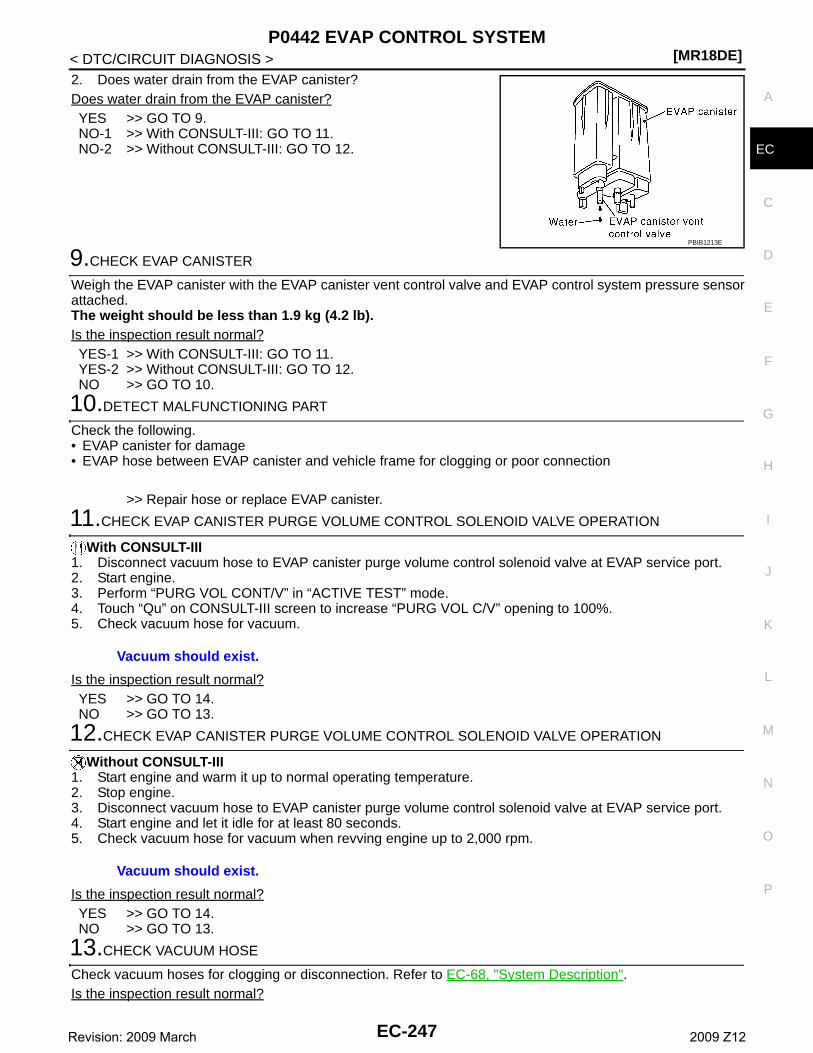
P0442 EVAP CONTROL SYSTEM[MR18DE]
C
D
E
F
G
H
I
J
K
L
M
A
C
N
P
O
< DTC/CIRCUIT DIAGNOSIS >
E
2. Does water drain from the EVAP canister?Does water drain from the EVAP canister?YES >> GO TO 9.NO-1 >> With CONSULT-III: GO TO 11.NO-2 >> Without CONSULT-III: GO TO 12.
9.CHECK EVAP CANISTER
Weigh the EVAP canister with the EVAP canister vent control valve and EVAP control system pressure sensorattached.The weight should be less than 1.9 kg (4.2 lb).Is the inspection result normal?YES-1 >> With CONSULT-III: GO TO 11.YES-2 >> Without CONSULT-III: GO TO 12.NO >> GO TO 10.
10.DETECT MALFUNCTIONING PART
Check the following.• EVAP canister for damage• EVAP hose between EVAP canister and vehicle frame for clogging or poor connection
>> Repair hose or replace EVAP canister.
11.CHECK EVAP CANISTER PURGE VOLUME CONTROL SOLENOID VALVE OPERATION
With CONSULT-III1. Disconnect vacuum hose to EVAP canister purge volume control solenoid valve at EVAP service port.2. Start engine.3. Perform “PURG VOL CONT/V” in “ACTIVE TEST” mode.4. Touch “Qu” on CONSULT-III screen to increase “PURG VOL C/V” opening to 100%.5. Check vacuum hose for vacuum.
Is the inspection result normal?YES >> GO TO 14.NO >> GO TO 13.
12.CHECK EVAP CANISTER PURGE VOLUME CONTROL SOLENOID VALVE OPERATION
Without CONSULT-III1. Start engine and warm it up to normal operating temperature.2. Stop engine.3. Disconnect vacuum hose to EVAP canister purge volume control solenoid valve at EVAP service port.4. Start engine and let it idle for at least 80 seconds.5. Check vacuum hose for vacuum when revving engine up to 2,000 rpm.
Is the inspection result normal?YES >> GO TO 14.NO >> GO TO 13.
13.CHECK VACUUM HOSE
Check vacuum hoses for clogging or disconnection. Refer to EC-68, "System Description".Is the inspection result normal?
PBIB1213E
Vacuum should exist.
Vacuum should exist.
EC-247Revision: 2009 March 2009 Z12
[MR18DE]P0442 EVAP CONTROL SYSTEM
< DTC/CIRCUIT DIAGNOSIS >YES >> GO TO 14.NO >> Repair or reconnect the hose.
14.CHECK EVAP CANISTER PURGE VOLUME CONTROL SOLENOID VALVE
Refer to EC-254, "Component Inspection".Is the inspection result normal?YES >> GO TO 15.NO >> Replace EVAP canister purge volume control solenoid valve.
15.CHECK FUEL TANK TEMPERATURE SENSOR
Refer to EC-210, "Component Inspection".Is the inspection result normal?YES >> GO TO 16.NO >> Replace fuel level sensor unit.
16.CHECK EVAP CONTROL SYSTEM PRESSURE SENSOR
Refer to EC-267, "DTC Logic".Is the inspection result normal?YES >> GO TO 17.NO >> Replace EVAP control system pressure sensor.
17.CHECK EVAP PURGE LINE
Check EVAP purge line (pipe, rubber tube, fuel tank and EVAP canister) for cracks or improper connection.Refer to EC-68, "System Description".Is the inspection result normal?YES >> GO TO 18.NO >> Repair or reconnect the hose.
18.CLEAN EVAP PURGE LINE
Clean EVAP purge line (pipe and rubber tube) using air blower.
>> GO TO 19.
19.CHECK EVAP/ORVR LINE
Check EVAP/ORVR line between EVAP canister and fuel tank for clogging, kink, looseness and improper con-nection. For location, refer to EC-407, "Description".Is the inspection result normal?YES >> GO TO 20.NO >> Repair or replace hoses and tubes.
20.CHECK RECIRCULATION LINE
Check recirculation line between fuel filler tube and fuel tank for clogging, kink, cracks, looseness andimproper connection.Is the inspection result normal?YES >> GO TO 21.NO >> Repair or replace hose, tube or fuel filler tube.
21.CHECK REFUELING EVAP VAPOR CUT VALVE
Refer to EC-410, "Component Inspection (Refueling EVAP vapor cut valve)".Is the inspection result normal?YES >> GO TO 22.NO >> Replace refueling EVAP vapor cut valve with fuel tank.
22.CHECK FUEL LEVEL SENSOR
Refer to MWI-42, "Component Function Check".Is the inspection result normal?YES >> GO TO 23.
EC-248Revision: 2009 March 2009 Z12
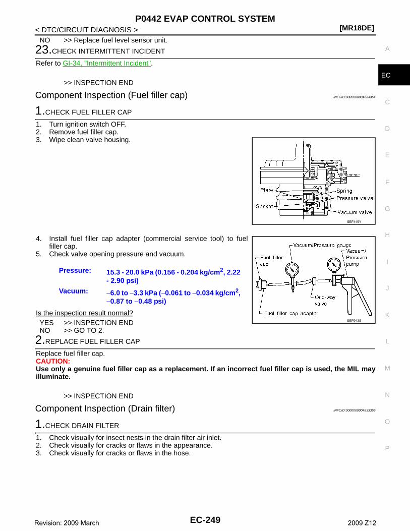
P0442 EVAP CONTROL SYSTEM[MR18DE]
C
D
E
F
G
H
I
J
K
L
M
A
C
N
P
O
< DTC/CIRCUIT DIAGNOSIS >
E
NO >> Replace fuel level sensor unit.
23.CHECK INTERMITTENT INCIDENT
Refer to GI-34, "Intermittent Incident".
>> INSPECTION END
Component Inspection (Fuel filler cap) INFOID:0000000004833354
1.CHECK FUEL FILLER CAP
1. Turn ignition switch OFF.2. Remove fuel filler cap.3. Wipe clean valve housing.
4. Install fuel filler cap adapter (commercial service tool) to fuelfiller cap.
5. Check valve opening pressure and vacuum.
Is the inspection result normal?YES >> INSPECTION ENDNO >> GO TO 2.
2.REPLACE FUEL FILLER CAP
Replace fuel filler cap.CAUTION:Use only a genuine fuel filler cap as a replacement. If an incorrect fuel filler cap is used, the MIL mayilluminate.
>> INSPECTION END
Component Inspection (Drain filter) INFOID:0000000004833355
1.CHECK DRAIN FILTER
1. Check visually for insect nests in the drain filter air inlet.2. Check visually for cracks or flaws in the appearance.3. Check visually for cracks or flaws in the hose.
SEF445Y
Pressure: 15.3 - 20.0 kPa (0.156 - 0.204 kg/cm2, 2.22 - 2.90 psi)
Vacuum: −6.0 to −3.3 kPa (−0.061 to −0.034 kg/cm2, −0.87 to −0.48 psi)
SEF943S
EC-249Revision: 2009 March 2009 Z12
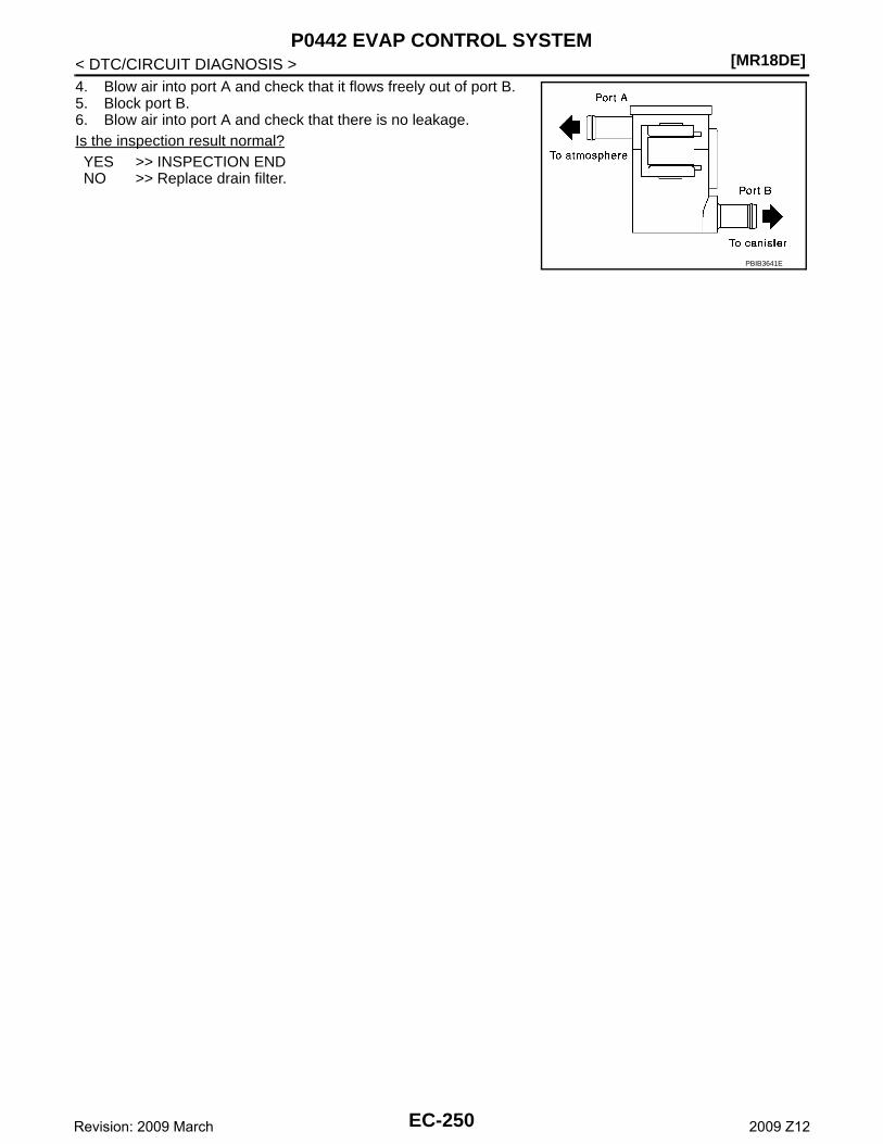
[MR18DE]P0442 EVAP CONTROL SYSTEM
< DTC/CIRCUIT DIAGNOSIS >4. Blow air into port A and check that it flows freely out of port B.5. Block port B.6. Blow air into port A and check that there is no leakage.Is the inspection result normal?YES >> INSPECTION ENDNO >> Replace drain filter.
PBIB3641E
EC-250Revision: 2009 March 2009 Z12
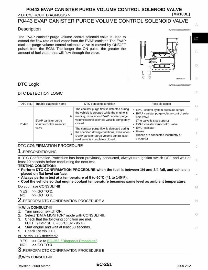
P0443 EVAP CANISTER PURGE VOLUME CONTROL SOLENOID VALVE[MR18DE]
C
D
E
F
G
H
I
J
K
L
M
A
C
N
P
O
< DTC/CIRCUIT DIAGNOSIS >
E
P0443 EVAP CANISTER PURGE VOLUME CONTROL SOLENOID VALVE
Description INFOID:0000000004833356
The EVAP canister purge volume control solenoid valve is used tocontrol the flow rate of fuel vapor from the EVAP canister. The EVAPcanister purge volume control solenoid valve is moved by ON/OFFpulses from the ECM. The longer the ON pulse, the greater theamount of fuel vapor that will flow through the valve.
DTC Logic INFOID:0000000004833357
DTC DETECTION LOGIC
DTC CONFIRMATION PROCEDURE
1.PRECONDITIONING
If DTC Confirmation Procedure has been previously conducted, always turn ignition switch OFF and wait atleast 10 seconds before conducting the next test.TESTING CONDITION:• Perform DTC CONFIRMATION PROCEDURE when the fuel is between 1/4 and 3/4 full, and vehicle is
placed on flat level surface.• Always perform test at a temperature of 5 to 60°C (41 to 140°F).• Cool the vehicle so that engine coolant temperature becomes same level as ambient temperature.Do you have CONSULT-IIIYES >> GO TO 2.NO >> GO TO 4.
2.PERFORM DTC CONFIRMATION PROCEDURE A
With CONSULT-III1. Turn ignition switch ON.2. Select “DATA MONITOR” mode with CONSULT-III.3. Check that the following condition are met.
FUEL T/TMP SE: 0 - 35°C (32 - 95°F)4. Start engine and wait at least 60 seconds.5. Check 1st trip DTC.Is 1st trip DTC detected?YES >> Go to EC-252, "Diagnosis Procedure".NO >> GO TO 3.
3.PERFORM DTC CONFIRMATION PROCEDURE B
With CONSULT-III
PBIA9215J
DTC No. Trouble diagnosis name DTC detecting condition Possible cause
P0443EVAP canister purge volume control solenoid valve
A
The canister purge flow is detected during the vehicle is stopped while the engine is running, even when EVAP canister purge volume control solenoid valve is completely closed.
• EVAP control system pressure sensor• EVAP canister purge volume control sole-
noid valve(The valve is stuck open.)
• EVAP canister vent control valve• EVAP canister• Hoses
(Hoses are connected incorrectly or clogged.)
B
The canister purge flow is detected during the specified driving conditions, even when EVAP canister purge volume control sole-noid valve is completely closed.
EC-251Revision: 2009 March 2009 Z12
[MR18DE]P0443 EVAP CANISTER PURGE VOLUME CONTROL SOLENOID VALVE
< DTC/CIRCUIT DIAGNOSIS >1. Start engine and warm it up to normal operating temperature.2. Turn ignition switch OFF and wait at least 10 seconds.3. Turn ignition switch ON.4. Select “PURG VOL CN/V P1444” of “EVAPORATIVE SYSTEM” in “DTC WORK SUPPORT” mode with
CONSULT-III.5. Touch “START”.6. Start engine and let it idle until “TESTING” on CONSULT-III changes to “COMPLETED”. (It will take
approximately 10 seconds.)If “TESTING” is not displayed after 5 minutes, retry from step 2.
7. Touch “SELF-DIAG RESULT”.Which is displayed on CONSULT-III?OK >> INSPECTION ENDNG >> Go to EC-252, "Diagnosis Procedure".
4.PERFORM DTC CONFIRMATION PROCEDURE A
With GST1. Turn ignition switch ON.2. Check the voltage between ECM harness connector and ground.
3. Start engine and wait at least 60 seconds.4. Check 1st trip DTC.Is 1st trip DTC detected?YES >> Go to EC-252, "Diagnosis Procedure".NO >> GO TO 5.
5.PERFORM DTC CONFIRMATION PROCEDURE
With GST1. Start engine and warm it up to normal operating temperature.2. Turn ignition switch OFF and wait at least 10 seconds.3. Start engine and let it idle for at least 20 seconds.4. Check 1st trip DTC.Is 1st trip DTC detected?YES >> Go to EC-252, "Diagnosis Procedure".NO >> INSPECTION END
Diagnosis Procedure INFOID:0000000004833359
1.CHECK EVAP CANISTER PURGE VOLUME CONTROL SOLENOID VALVE POWER SUPPLY CIRCUIT
1. Turn ignition switch OFF.2. Disconnect EVAP canister purge volume control solenoid valve harness connector.3. Turn ignition switch ON.4. Check the voltage between EVAP canister purge volume control solenoid valve harness connector and
ground.
Is the inspection result normal?YES >> GO TO 3.NO >> GO TO 2.
ECMGround Voltage (V)
Connector Terminal
F843
(Fuel tank temperature sensor signal)Ground 3.1 - 4.0
EVAP canister purge volume control solenoid valve Ground Voltage
Connector Terminal
F32 1 Ground Battery voltage
EC-252Revision: 2009 March 2009 Z12
P0443 EVAP CANISTER PURGE VOLUME CONTROL SOLENOID VALVE[MR18DE]
C
D
E
F
G
H
I
J
K
L
M
A
C
N
P
O
< DTC/CIRCUIT DIAGNOSIS >
E
2.DETECT MALFUNCTIONING PART
Check the following.• Harness connectors E8, F1• IPDM E/R harness connector E14• Harness for open or short between EVAP canister purge volume control solenoid valve and IPDM E/R• Harness for open or short between EVAP canister purge volume control solenoid valve and ECM
>> Repair open circuit or short to ground or short to power in harness or connectors.
3.CHECK EVAP CANISTER PURGE VOLUME CONTROL SOLENOID VALVE OUTPUT SIGNAL CIRCUITFOR OPEN AND SHORT
1. Turn ignition switch OFF.2. Disconnect ECM harness connector.3. Check the continuity between EVAP canister purge volume control solenoid valve harness connector and
ECM harness connector.
4. Also check harness for short to ground and short to power.Is the inspection result normal?YES >> GO TO 4.NO >> Repair open circuit or short to ground or short to power in harness or connectors.
4.CHECK EVAP CONTROL SYSTEM PRESSURE SENSOR CONNECTOR
1. Disconnect EVAP control system pressure sensor harness connector.2. Check connectors for water.
Is the inspection result normal?YES >> GO TO 5.NO >> Replace EVAP control system pressure sensor.
5.CHECK EVAP CONTROL SYSTEM PRESSURE SENSOR
Refer to EC-269, "Component Inspection".Is the inspection result normal?YES-1 >> With CONSULT-III: GO TO 6.YES-2 >> Without CONSULT-III: GO TO 7.NO >> Replace EVAP control system pressure sensor.
6.CHECK EVAP CANISTER PURGE VOLUME CONTROL SOLENOID VALVE
With CONSULT-III1. Turn ignition switch OFF.2. Reconnect harness connectors disconnected.3. Start engine.4. Perform “PURG VOL CONT/V” in “ACTIVE TEST” mode with CONSULT-III. Check that engine speed var-
ies according to the valve opening.Is the inspection result normal?YES >> GO TO 8.NO >> GO TO 7.
7.CHECK EVAP CANISTER PURGE VOLUME CONTROL SOLENOID VALVE
Refer to EC-254, "Component Inspection".Is the inspection result normal?
EVAP canister purge volume control solenoid valve
ECMContinuity
Connector Terminal Connector Terminal
F32 2 F7 9 Existed
Water should not exist.
EC-253Revision: 2009 March 2009 Z12
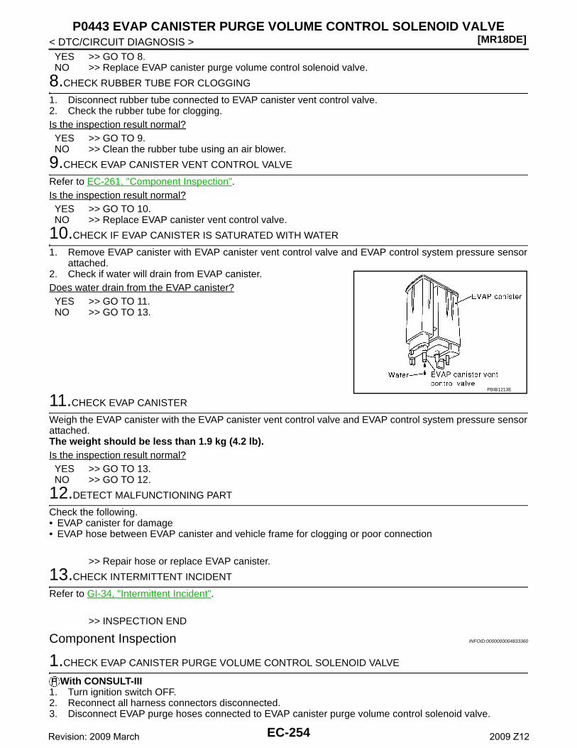
[MR18DE]P0443 EVAP CANISTER PURGE VOLUME CONTROL SOLENOID VALVE
< DTC/CIRCUIT DIAGNOSIS >YES >> GO TO 8.NO >> Replace EVAP canister purge volume control solenoid valve.
8.CHECK RUBBER TUBE FOR CLOGGING
1. Disconnect rubber tube connected to EVAP canister vent control valve.2. Check the rubber tube for clogging.Is the inspection result normal?YES >> GO TO 9.NO >> Clean the rubber tube using an air blower.
9.CHECK EVAP CANISTER VENT CONTROL VALVE
Refer to EC-261, "Component Inspection".Is the inspection result normal?YES >> GO TO 10.NO >> Replace EVAP canister vent control valve.
10.CHECK IF EVAP CANISTER IS SATURATED WITH WATER
1. Remove EVAP canister with EVAP canister vent control valve and EVAP control system pressure sensorattached.
2. Check if water will drain from EVAP canister.Does water drain from the EVAP canister?YES >> GO TO 11.NO >> GO TO 13.
11.CHECK EVAP CANISTER
Weigh the EVAP canister with the EVAP canister vent control valve and EVAP control system pressure sensorattached.The weight should be less than 1.9 kg (4.2 lb).Is the inspection result normal?YES >> GO TO 13.NO >> GO TO 12.
12.DETECT MALFUNCTIONING PART
Check the following.• EVAP canister for damage• EVAP hose between EVAP canister and vehicle frame for clogging or poor connection
>> Repair hose or replace EVAP canister.
13.CHECK INTERMITTENT INCIDENT
Refer to GI-34, "Intermittent Incident".
>> INSPECTION END
Component Inspection INFOID:0000000004833360
1.CHECK EVAP CANISTER PURGE VOLUME CONTROL SOLENOID VALVE
With CONSULT-III1. Turn ignition switch OFF.2. Reconnect all harness connectors disconnected.3. Disconnect EVAP purge hoses connected to EVAP canister purge volume control solenoid valve.
PBIB1213E
EC-254Revision: 2009 March 2009 Z12
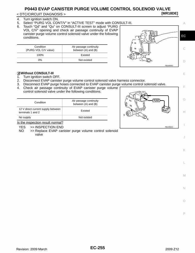
P0443 EVAP CANISTER PURGE VOLUME CONTROL SOLENOID VALVE[MR18DE]
C
D
E
F
G
H
I
J
K
L
M
A
C
N
P
O
< DTC/CIRCUIT DIAGNOSIS >
E
4. Turn ignition switch ON.5. Select “PURG VOL CONT/V” in “ACTIVE TEST” mode with CONSULT-III.6. Touch “Qd” and “Qu” on CONSULT-III screen to adjust “PURG
VOL C/V” opening and check air passage continuity of EVAPcanister purge volume control solenoid valve under the followingconditions.
Without CONSULT-III1. Turn ignition switch OFF.2. Disconnect EVAP canister purge volume control solenoid valve harness connector.3. Disconnect EVAP purge hoses connected to EVAP canister purge volume control solenoid valve.4. Check air passage continuity of EVAP canister purge volume
control solenoid valve under the following conditions.
Is the inspection result normal?YES >> INSPECTION ENDNO >> Replace EVAP canister purge volume control solenoid
valve
Condition(PURG VOL C/V value)
Air passage continuity between (A) and (B)
100% Existed
0% Not existed
PBIA9668J
ConditionAir passage continuity between (A) and (B)
12 V direct current supply between terminals 1 and 2
Existed
No supply Not existed
PBIA9560J
EC-255Revision: 2009 March 2009 Z12
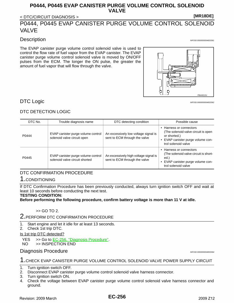
[MR18DE]
P0444, P0445 EVAP CANISTER PURGE VOLUME CONTROL SOLENOID VALVE
< DTC/CIRCUIT DIAGNOSIS >
P0444, P0445 EVAP CANISTER PURGE VOLUME CONTROL SOLENOIDVALVE
Description INFOID:0000000004833361
The EVAP canister purge volume control solenoid valve is used tocontrol the flow rate of fuel vapor from the EVAP canister. The EVAPcanister purge volume control solenoid valve is moved by ON/OFFpulses from the ECM. The longer the ON pulse, the greater theamount of fuel vapor that will flow through the valve.
DTC Logic INFOID:0000000004833362
DTC DETECTION LOGIC
DTC CONFIRMATION PROCEDURE
1.CONDITIONING
If DTC Confirmation Procedure has been previously conducted, always turn ignition switch OFF and wait atleast 10 seconds before conducting the next test.TESTING CONDITION:Before performing the following procedure, confirm battery voltage is more than 11 V at idle.
>> GO TO 2.
2.PERFORM DTC CONFIRMATION PROCEDURE
1. Start engine and let it idle for at least 13 seconds.2. Check 1st trip DTC.Is 1st trip DTC detected?YES >> Go to EC-256, "Diagnosis Procedure".NO >> INSPECTION END
Diagnosis Procedure INFOID:0000000004833364
1.CHECK EVAP CANISTER PURGE VOLUME CONTROL SOLENOID VALVE POWER SUPPLY CIRCUIT
1. Turn ignition switch OFF.2. Disconnect EVAP canister purge volume control solenoid valve harness connector.3. Turn ignition switch ON.4. Check the voltage between EVAP canister purge volume control solenoid valve harness connector and
ground.
PBIA9215J
DTC No. Trouble diagnosis name DTC detecting condition Possible cause
P0444EVAP canister purge volume control solenoid valve circuit open
An excessively low voltage signal is sent to ECM through the valve
• Harness or connectors(The solenoid valve circuit is open or shorted.)
• EVAP canister purge volume con-trol solenoid valve
P0445EVAP canister purge volume control solenoid valve circuit shorted
An excessively high voltage signal is sent to ECM through the valve
• Harness or connectors(The solenoid valve circuit is short-ed.)
• EVAP canister purge volume con-trol solenoid valve
EC-256Revision: 2009 March 2009 Z12
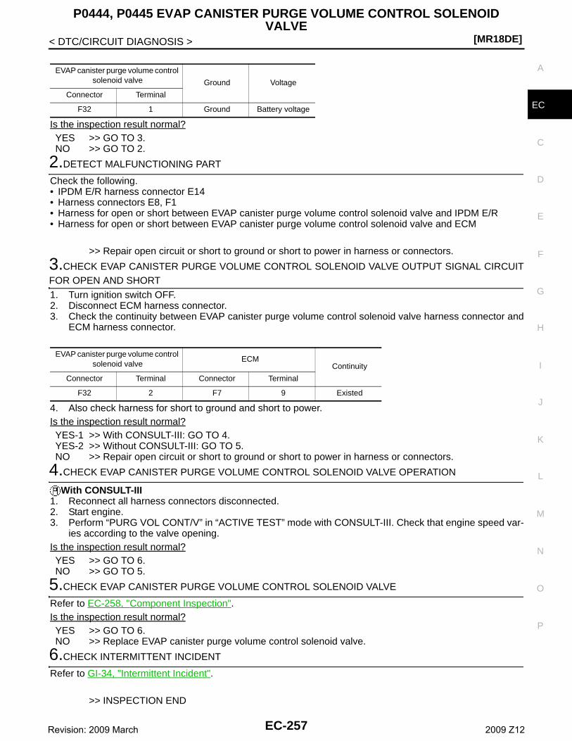
P0444, P0445 EVAP CANISTER PURGE VOLUME CONTROL SOLENOID VALVE
[MR18DE]
C
D
E
F
G
H
I
J
K
L
M
A
C
N
P
O
< DTC/CIRCUIT DIAGNOSIS >
E
Is the inspection result normal?YES >> GO TO 3.NO >> GO TO 2.
2.DETECT MALFUNCTIONING PART
Check the following.• IPDM E/R harness connector E14• Harness connectors E8, F1• Harness for open or short between EVAP canister purge volume control solenoid valve and IPDM E/R• Harness for open or short between EVAP canister purge volume control solenoid valve and ECM
>> Repair open circuit or short to ground or short to power in harness or connectors.
3.CHECK EVAP CANISTER PURGE VOLUME CONTROL SOLENOID VALVE OUTPUT SIGNAL CIRCUITFOR OPEN AND SHORT
1. Turn ignition switch OFF.2. Disconnect ECM harness connector.3. Check the continuity between EVAP canister purge volume control solenoid valve harness connector and
ECM harness connector.
4. Also check harness for short to ground and short to power.Is the inspection result normal?YES-1 >> With CONSULT-III: GO TO 4.YES-2 >> Without CONSULT-III: GO TO 5.NO >> Repair open circuit or short to ground or short to power in harness or connectors.
4.CHECK EVAP CANISTER PURGE VOLUME CONTROL SOLENOID VALVE OPERATION
With CONSULT-III1. Reconnect all harness connectors disconnected.2. Start engine.3. Perform “PURG VOL CONT/V” in “ACTIVE TEST” mode with CONSULT-III. Check that engine speed var-
ies according to the valve opening.Is the inspection result normal?YES >> GO TO 6.NO >> GO TO 5.
5.CHECK EVAP CANISTER PURGE VOLUME CONTROL SOLENOID VALVE
Refer to EC-258, "Component Inspection".Is the inspection result normal?YES >> GO TO 6.NO >> Replace EVAP canister purge volume control solenoid valve.
6.CHECK INTERMITTENT INCIDENT
Refer to GI-34, "Intermittent Incident".
>> INSPECTION END
EVAP canister purge volume control solenoid valve Ground Voltage
Connector Terminal
F32 1 Ground Battery voltage
EVAP canister purge volume control solenoid valve
ECMContinuity
Connector Terminal Connector Terminal
F32 2 F7 9 Existed
EC-257Revision: 2009 March 2009 Z12
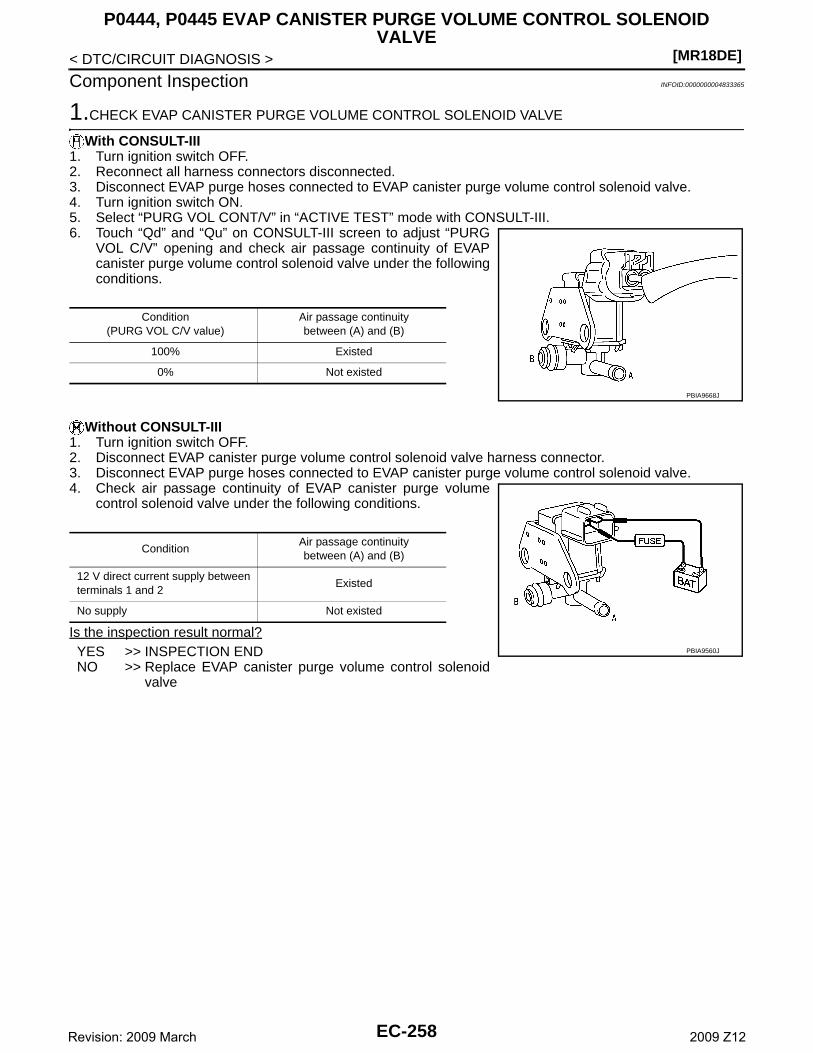
[MR18DE]
P0444, P0445 EVAP CANISTER PURGE VOLUME CONTROL SOLENOID VALVE
< DTC/CIRCUIT DIAGNOSIS >
Component Inspection INFOID:0000000004833365
1.CHECK EVAP CANISTER PURGE VOLUME CONTROL SOLENOID VALVE
With CONSULT-III1. Turn ignition switch OFF.2. Reconnect all harness connectors disconnected.3. Disconnect EVAP purge hoses connected to EVAP canister purge volume control solenoid valve.4. Turn ignition switch ON.5. Select “PURG VOL CONT/V” in “ACTIVE TEST” mode with CONSULT-III.6. Touch “Qd” and “Qu” on CONSULT-III screen to adjust “PURG
VOL C/V” opening and check air passage continuity of EVAPcanister purge volume control solenoid valve under the followingconditions.
Without CONSULT-III1. Turn ignition switch OFF.2. Disconnect EVAP canister purge volume control solenoid valve harness connector.3. Disconnect EVAP purge hoses connected to EVAP canister purge volume control solenoid valve.4. Check air passage continuity of EVAP canister purge volume
control solenoid valve under the following conditions.
Is the inspection result normal?YES >> INSPECTION ENDNO >> Replace EVAP canister purge volume control solenoid
valve
Condition(PURG VOL C/V value)
Air passage continuity between (A) and (B)
100% Existed
0% Not existed
PBIA9668J
ConditionAir passage continuity between (A) and (B)
12 V direct current supply between terminals 1 and 2
Existed
No supply Not existed
PBIA9560J
EC-258Revision: 2009 March 2009 Z12
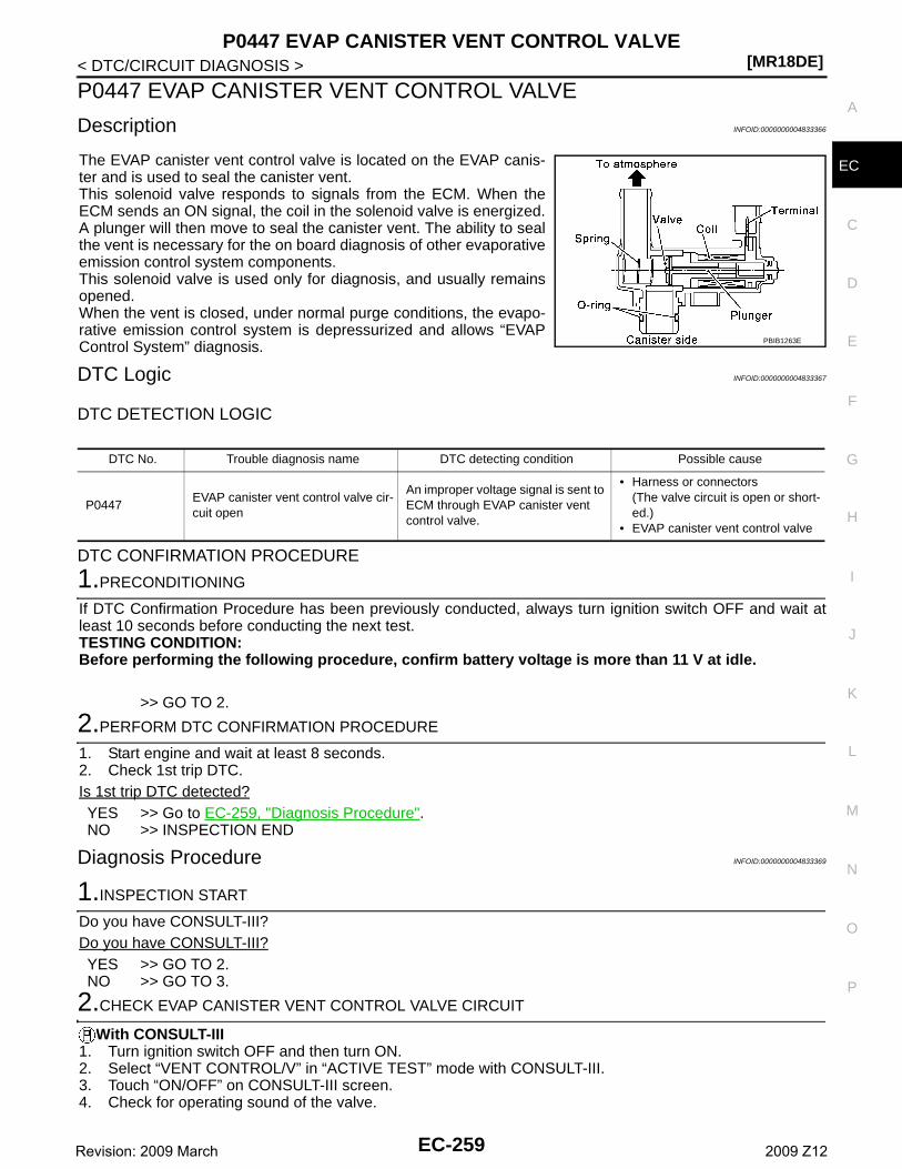
P0447 EVAP CANISTER VENT CONTROL VALVE[MR18DE]
C
D
E
F
G
H
I
J
K
L
M
A
C
N
P
O
< DTC/CIRCUIT DIAGNOSIS >
E
P0447 EVAP CANISTER VENT CONTROL VALVE
Description INFOID:0000000004833366
The EVAP canister vent control valve is located on the EVAP canis-ter and is used to seal the canister vent.This solenoid valve responds to signals from the ECM. When theECM sends an ON signal, the coil in the solenoid valve is energized.A plunger will then move to seal the canister vent. The ability to sealthe vent is necessary for the on board diagnosis of other evaporativeemission control system components.This solenoid valve is used only for diagnosis, and usually remainsopened.When the vent is closed, under normal purge conditions, the evapo-rative emission control system is depressurized and allows “EVAPControl System” diagnosis.
DTC Logic INFOID:0000000004833367
DTC DETECTION LOGIC
DTC CONFIRMATION PROCEDURE
1.PRECONDITIONING
If DTC Confirmation Procedure has been previously conducted, always turn ignition switch OFF and wait atleast 10 seconds before conducting the next test.TESTING CONDITION:Before performing the following procedure, confirm battery voltage is more than 11 V at idle.
>> GO TO 2.
2.PERFORM DTC CONFIRMATION PROCEDURE
1. Start engine and wait at least 8 seconds.2. Check 1st trip DTC.Is 1st trip DTC detected?YES >> Go to EC-259, "Diagnosis Procedure".NO >> INSPECTION END
Diagnosis Procedure INFOID:0000000004833369
1.INSPECTION START
Do you have CONSULT-III?Do you have CONSULT-III?YES >> GO TO 2.NO >> GO TO 3.
2.CHECK EVAP CANISTER VENT CONTROL VALVE CIRCUIT
With CONSULT-III1. Turn ignition switch OFF and then turn ON.2. Select “VENT CONTROL/V” in “ACTIVE TEST” mode with CONSULT-III.3. Touch “ON/OFF” on CONSULT-III screen.4. Check for operating sound of the valve.
PBIB1263E
DTC No. Trouble diagnosis name DTC detecting condition Possible cause
P0447EVAP canister vent control valve cir-cuit open
An improper voltage signal is sent to ECM through EVAP canister vent control valve.
• Harness or connectors(The valve circuit is open or short-ed.)
• EVAP canister vent control valve
EC-259Revision: 2009 March 2009 Z12
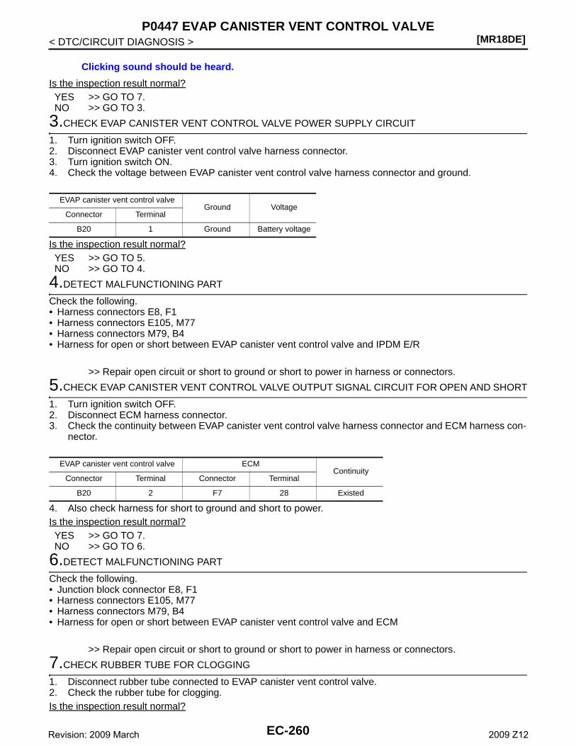
[MR18DE]P0447 EVAP CANISTER VENT CONTROL VALVE
< DTC/CIRCUIT DIAGNOSIS >
Is the inspection result normal?YES >> GO TO 7.NO >> GO TO 3.
3.CHECK EVAP CANISTER VENT CONTROL VALVE POWER SUPPLY CIRCUIT
1. Turn ignition switch OFF.2. Disconnect EVAP canister vent control valve harness connector.3. Turn ignition switch ON.4. Check the voltage between EVAP canister vent control valve harness connector and ground.
Is the inspection result normal?YES >> GO TO 5.NO >> GO TO 4.
4.DETECT MALFUNCTIONING PART
Check the following.• Harness connectors E8, F1• Harness connectors E105, M77• Harness connectors M79, B4• Harness for open or short between EVAP canister vent control valve and IPDM E/R
>> Repair open circuit or short to ground or short to power in harness or connectors.
5.CHECK EVAP CANISTER VENT CONTROL VALVE OUTPUT SIGNAL CIRCUIT FOR OPEN AND SHORT
1. Turn ignition switch OFF.2. Disconnect ECM harness connector.3. Check the continuity between EVAP canister vent control valve harness connector and ECM harness con-
nector.
4. Also check harness for short to ground and short to power.Is the inspection result normal?YES >> GO TO 7.NO >> GO TO 6.
6.DETECT MALFUNCTIONING PART
Check the following.• Junction block connector E8, F1• Harness connectors E105, M77• Harness connectors M79, B4• Harness for open or short between EVAP canister vent control valve and ECM
>> Repair open circuit or short to ground or short to power in harness or connectors.
7.CHECK RUBBER TUBE FOR CLOGGING
1. Disconnect rubber tube connected to EVAP canister vent control valve.2. Check the rubber tube for clogging.Is the inspection result normal?
Clicking sound should be heard.
EVAP canister vent control valveGround Voltage
Connector Terminal
B20 1 Ground Battery voltage
EVAP canister vent control valve ECMContinuity
Connector Terminal Connector Terminal
B20 2 F7 28 Existed
EC-260Revision: 2009 March 2009 Z12
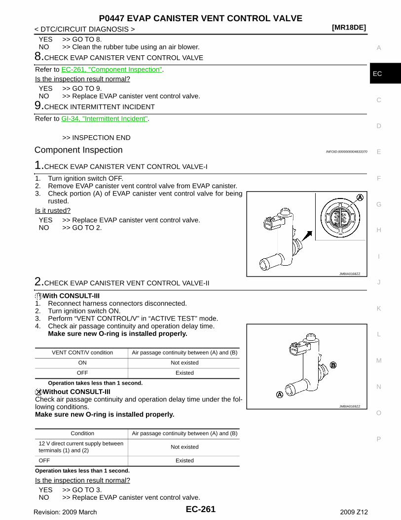
P0447 EVAP CANISTER VENT CONTROL VALVE[MR18DE]
C
D
E
F
G
H
I
J
K
L
M
A
C
N
P
O
< DTC/CIRCUIT DIAGNOSIS >
E
YES >> GO TO 8.NO >> Clean the rubber tube using an air blower.
8.CHECK EVAP CANISTER VENT CONTROL VALVE
Refer to EC-261, "Component Inspection".Is the inspection result normal?YES >> GO TO 9.NO >> Replace EVAP canister vent control valve.
9.CHECK INTERMITTENT INCIDENT
Refer to GI-34, "Intermittent Incident".
>> INSPECTION END
Component Inspection INFOID:0000000004833370
1.CHECK EVAP CANISTER VENT CONTROL VALVE-I
1. Turn ignition switch OFF.2. Remove EVAP canister vent control valve from EVAP canister.3. Check portion (A) of EVAP canister vent control valve for being
rusted.Is it rusted?YES >> Replace EVAP canister vent control valve.NO >> GO TO 2.
2.CHECK EVAP CANISTER VENT CONTROL VALVE-II
With CONSULT-III1. Reconnect harness connectors disconnected.2. Turn ignition switch ON.3. Perform “VENT CONTROL/V” in “ACTIVE TEST” mode.4. Check air passage continuity and operation delay time.
Make sure new O-ring is installed properly.
Operation takes less than 1 second.
Without CONSULT-IIICheck air passage continuity and operation delay time under the fol-lowing conditions.Make sure new O-ring is installed properly.
Operation takes less than 1 second.
Is the inspection result normal?YES >> GO TO 3.NO >> Replace EVAP canister vent control valve.
JMBIA0168ZZ
VENT CONT/V condition Air passage continuity between (A) and (B)
ON Not existed
OFF Existed
Condition Air passage continuity between (A) and (B)
12 V direct current supply between terminals (1) and (2)
Not existed
OFF Existed
JMBIA0169ZZ
EC-261Revision: 2009 March 2009 Z12
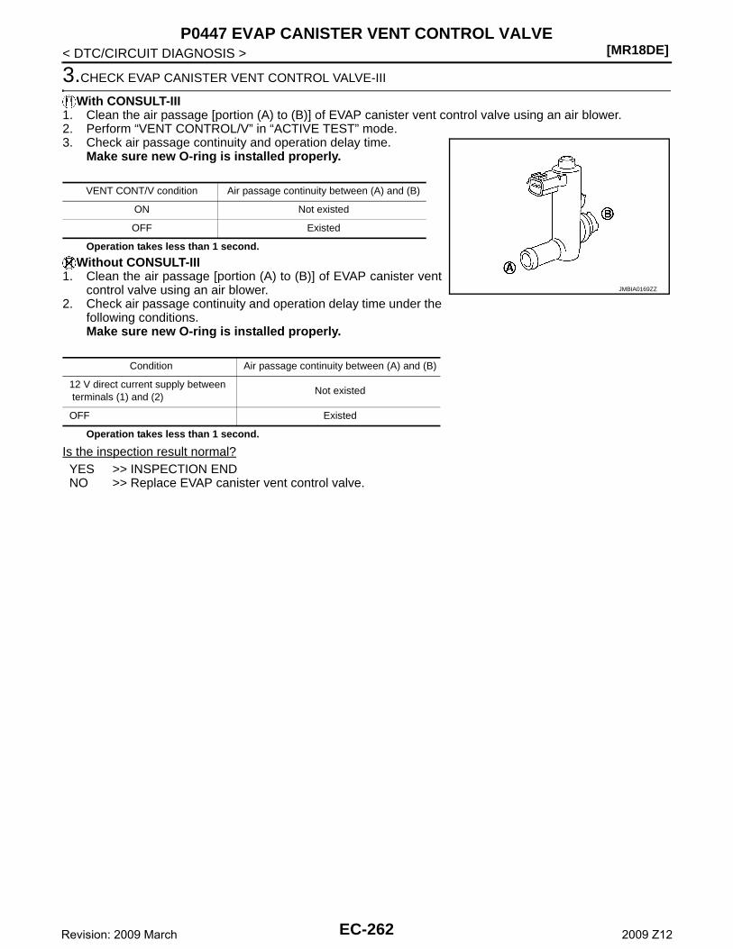
[MR18DE]P0447 EVAP CANISTER VENT CONTROL VALVE
< DTC/CIRCUIT DIAGNOSIS >
3.CHECK EVAP CANISTER VENT CONTROL VALVE-III
With CONSULT-III1. Clean the air passage [portion (A) to (B)] of EVAP canister vent control valve using an air blower.2. Perform “VENT CONTROL/V” in “ACTIVE TEST” mode.3. Check air passage continuity and operation delay time.
Make sure new O-ring is installed properly.
Operation takes less than 1 second.
Without CONSULT-III1. Clean the air passage [portion (A) to (B)] of EVAP canister vent
control valve using an air blower.2. Check air passage continuity and operation delay time under the
following conditions.Make sure new O-ring is installed properly.
Operation takes less than 1 second.
Is the inspection result normal?YES >> INSPECTION ENDNO >> Replace EVAP canister vent control valve.
VENT CONT/V condition Air passage continuity between (A) and (B)
ON Not existed
OFF Existed
Condition Air passage continuity between (A) and (B)
12 V direct current supply between terminals (1) and (2)
Not existed
OFF Existed
JMBIA0169ZZ
EC-262Revision: 2009 March 2009 Z12
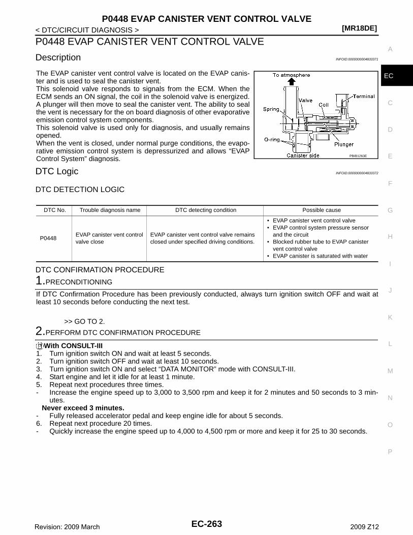
P0448 EVAP CANISTER VENT CONTROL VALVE[MR18DE]
C
D
E
F
G
H
I
J
K
L
M
A
C
N
P
O
< DTC/CIRCUIT DIAGNOSIS >
E
P0448 EVAP CANISTER VENT CONTROL VALVE
Description INFOID:0000000004833371
The EVAP canister vent control valve is located on the EVAP canis-ter and is used to seal the canister vent.This solenoid valve responds to signals from the ECM. When theECM sends an ON signal, the coil in the solenoid valve is energized.A plunger will then move to seal the canister vent. The ability to sealthe vent is necessary for the on board diagnosis of other evaporativeemission control system components.This solenoid valve is used only for diagnosis, and usually remainsopened.When the vent is closed, under normal purge conditions, the evapo-rative emission control system is depressurized and allows “EVAPControl System” diagnosis.
DTC Logic INFOID:0000000004833372
DTC DETECTION LOGIC
DTC CONFIRMATION PROCEDURE
1.PRECONDITIONING
If DTC Confirmation Procedure has been previously conducted, always turn ignition switch OFF and wait atleast 10 seconds before conducting the next test.
>> GO TO 2.
2.PERFORM DTC CONFIRMATION PROCEDURE
With CONSULT-III1. Turn ignition switch ON and wait at least 5 seconds.2. Turn ignition switch OFF and wait at least 10 seconds.3. Turn ignition switch ON and select “DATA MONITOR” mode with CONSULT-III.4. Start engine and let it idle for at least 1 minute. 5. Repeat next procedures three times.- Increase the engine speed up to 3,000 to 3,500 rpm and keep it for 2 minutes and 50 seconds to 3 min-
utes.Never exceed 3 minutes.
- Fully released accelerator pedal and keep engine idle for about 5 seconds.6. Repeat next procedure 20 times.- Quickly increase the engine speed up to 4,000 to 4,500 rpm or more and keep it for 25 to 30 seconds.
PBIB1263E
DTC No. Trouble diagnosis name DTC detecting condition Possible cause
P0448EVAP canister vent control valve close
EVAP canister vent control valve remains closed under specified driving conditions.
• EVAP canister vent control valve• EVAP control system pressure sensor
and the circuit• Blocked rubber tube to EVAP canister
vent control valve• EVAP canister is saturated with water
EC-263Revision: 2009 March 2009 Z12
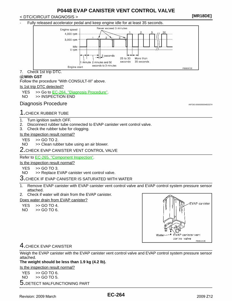
[MR18DE]P0448 EVAP CANISTER VENT CONTROL VALVE
< DTC/CIRCUIT DIAGNOSIS >- Fully released accelerator pedal and keep engine idle for at least 35 seconds.
7. Check 1st trip DTC.With GST
Follow the procedure “With CONSULT-III” above.Is 1st trip DTC detected?YES >> Go to EC-264, "Diagnosis Procedure".NO >> INSPECTION END
Diagnosis Procedure INFOID:0000000004833374
1.CHECK RUBBER TUBE
1. Turn ignition switch OFF.2. Disconnect rubber tube connected to EVAP canister vent control valve.3. Check the rubber tube for clogging.Is the inspection result normal?YES >> GO TO 2.NO >> Clean rubber tube using an air blower.
2.CHECK EVAP CANISTER VENT CONTROL VALVE
Refer to EC-265, "Component Inspection".Is the inspection result normal?YES >> GO TO 3.NO >> Replace EVAP canister vent control valve.
3.CHECK IF EVAP CANISTER IS SATURATED WITH WATER
1. Remove EVAP canister with EVAP canister vent control valve and EVAP control system pressure sensorattached.
2. Check if water will drain from the EVAP canister.Does water drain from EVAP canister?YES >> GO TO 4.NO >> GO TO 6.
4.CHECK EVAP CANISTER
Weigh the EVAP canister with the EVAP canister vent control valve and EVAP control system pressure sensorattached.The weight should be less than 1.9 kg (4.2 lb).Is the inspection result normal?YES >> GO TO 6.NO >> GO TO 5.
5.DETECT MALFUNCTIONING PART
PBIB0972E
PBIB1213E
EC-264Revision: 2009 March 2009 Z12
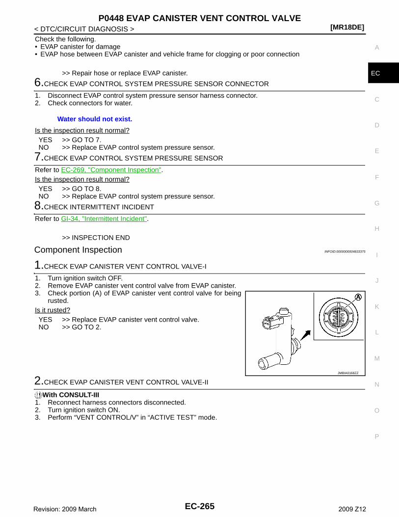
P0448 EVAP CANISTER VENT CONTROL VALVE[MR18DE]
C
D
E
F
G
H
I
J
K
L
M
A
C
N
P
O
< DTC/CIRCUIT DIAGNOSIS >
E
Check the following.• EVAP canister for damage• EVAP hose between EVAP canister and vehicle frame for clogging or poor connection
>> Repair hose or replace EVAP canister.
6.CHECK EVAP CONTROL SYSTEM PRESSURE SENSOR CONNECTOR
1. Disconnect EVAP control system pressure sensor harness connector.2. Check connectors for water.
Is the inspection result normal?YES >> GO TO 7.NO >> Replace EVAP control system pressure sensor.
7.CHECK EVAP CONTROL SYSTEM PRESSURE SENSOR
Refer to EC-269, "Component Inspection".Is the inspection result normal?YES >> GO TO 8.NO >> Replace EVAP control system pressure sensor.
8.CHECK INTERMITTENT INCIDENT
Refer to GI-34, "Intermittent Incident".
>> INSPECTION END
Component Inspection INFOID:0000000004833375
1.CHECK EVAP CANISTER VENT CONTROL VALVE-I
1. Turn ignition switch OFF.2. Remove EVAP canister vent control valve from EVAP canister.3. Check portion (A) of EVAP canister vent control valve for being
rusted.Is it rusted?YES >> Replace EVAP canister vent control valve.NO >> GO TO 2.
2.CHECK EVAP CANISTER VENT CONTROL VALVE-II
With CONSULT-III1. Reconnect harness connectors disconnected.2. Turn ignition switch ON.3. Perform “VENT CONTROL/V” in “ACTIVE TEST” mode.
Water should not exist.
JMBIA0168ZZ
EC-265Revision: 2009 March 2009 Z12
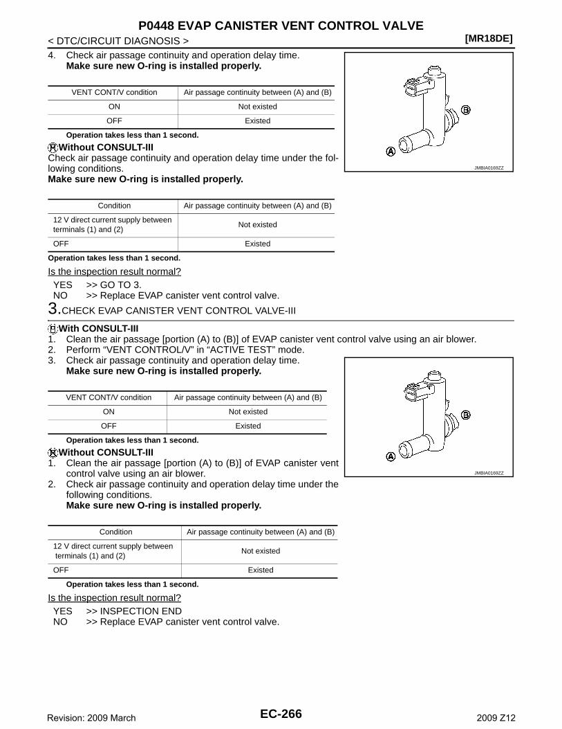
[MR18DE]P0448 EVAP CANISTER VENT CONTROL VALVE
< DTC/CIRCUIT DIAGNOSIS >4. Check air passage continuity and operation delay time.
Make sure new O-ring is installed properly.
Operation takes less than 1 second.
Without CONSULT-IIICheck air passage continuity and operation delay time under the fol-lowing conditions.Make sure new O-ring is installed properly.
Operation takes less than 1 second.
Is the inspection result normal?YES >> GO TO 3.NO >> Replace EVAP canister vent control valve.
3.CHECK EVAP CANISTER VENT CONTROL VALVE-III
With CONSULT-III1. Clean the air passage [portion (A) to (B)] of EVAP canister vent control valve using an air blower.2. Perform “VENT CONTROL/V” in “ACTIVE TEST” mode.3. Check air passage continuity and operation delay time.
Make sure new O-ring is installed properly.
Operation takes less than 1 second.
Without CONSULT-III1. Clean the air passage [portion (A) to (B)] of EVAP canister vent
control valve using an air blower.2. Check air passage continuity and operation delay time under the
following conditions.Make sure new O-ring is installed properly.
Operation takes less than 1 second.
Is the inspection result normal?YES >> INSPECTION ENDNO >> Replace EVAP canister vent control valve.
VENT CONT/V condition Air passage continuity between (A) and (B)
ON Not existed
OFF Existed
Condition Air passage continuity between (A) and (B)
12 V direct current supply between terminals (1) and (2)
Not existed
OFF Existed
JMBIA0169ZZ
VENT CONT/V condition Air passage continuity between (A) and (B)
ON Not existed
OFF Existed
Condition Air passage continuity between (A) and (B)
12 V direct current supply between terminals (1) and (2)
Not existed
OFF Existed
JMBIA0169ZZ
EC-266Revision: 2009 March 2009 Z12
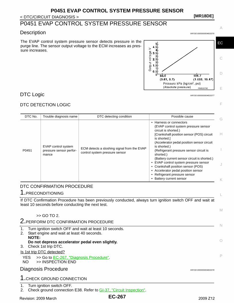
P0451 EVAP CONTROL SYSTEM PRESSURE SENSOR[MR18DE]
C
D
E
F
G
H
I
J
K
L
M
A
C
N
P
O
< DTC/CIRCUIT DIAGNOSIS >
E
P0451 EVAP CONTROL SYSTEM PRESSURE SENSOR
Description INFOID:0000000004833376
The EVAP control system pressure sensor detects pressure in thepurge line. The sensor output voltage to the ECM increases as pres-sure increases.
DTC Logic INFOID:0000000004833377
DTC DETECTION LOGIC
DTC CONFIRMATION PROCEDURE
1.PRECONDITIONING
If DTC Confirmation Procedure has been previously conducted, always turn ignition switch OFF and wait atleast 10 seconds before conducting the next test.
>> GO TO 2.
2.PERFORM DTC CONFIRMATION PROCEDURE
1. Turn ignition switch OFF and wait at least 10 seconds.2. Start engine and wait at least 40 seconds.
NOTE:Do not depress accelerator pedal even slightly.
3. Check 1st trip DTC.Is 1st trip DTC detected?YES >> Go to EC-267, "Diagnosis Procedure".NO >> INSPECTION END
Diagnosis Procedure INFOID:0000000004833378
1.CHECK GROUND CONNECTION
1. Turn ignition switch OFF.2. Check ground connection E38. Refer to GI-37, "Circuit Inspection".
PBIB3370E
DTC No. Trouble diagnosis name DTC detecting condition Possible cause
P0451EVAP control system pressure sensor perfor-mance
ECM detects a sloshing signal from the EVAP control system pressure sensor
• Harness or connectors(EVAP control system pressure sensor circuit is shorted.)[Crankshaft position sensor (POS) circuit is shorted.](Accelerator pedal position sensor circuit is shorted.)(Refrigerant pressure sensor circuit is shorted.)(Battery current sensor circuit is shorted.)
• EVAP control system pressure sensor• Crankshaft position sensor (POS)• Accelerator pedal position sensor• Refrigerant pressure sensor• Battery current sensor
EC-267Revision: 2009 March 2009 Z12
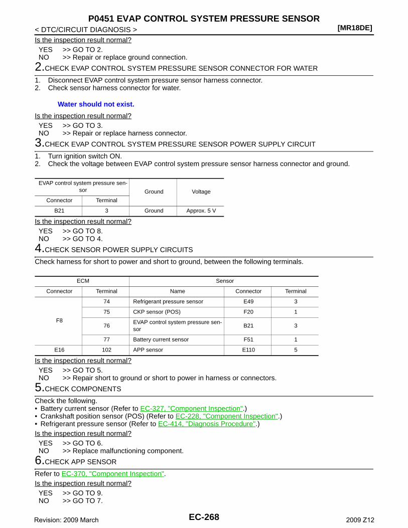
[MR18DE]P0451 EVAP CONTROL SYSTEM PRESSURE SENSOR
< DTC/CIRCUIT DIAGNOSIS >Is the inspection result normal?YES >> GO TO 2.NO >> Repair or replace ground connection.
2.CHECK EVAP CONTROL SYSTEM PRESSURE SENSOR CONNECTOR FOR WATER
1. Disconnect EVAP control system pressure sensor harness connector.2. Check sensor harness connector for water.
Is the inspection result normal?YES >> GO TO 3.NO >> Repair or replace harness connector.
3.CHECK EVAP CONTROL SYSTEM PRESSURE SENSOR POWER SUPPLY CIRCUIT
1. Turn ignition switch ON.2. Check the voltage between EVAP control system pressure sensor harness connector and ground.
Is the inspection result normal?YES >> GO TO 8.NO >> GO TO 4.
4.CHECK SENSOR POWER SUPPLY CIRCUITS
Check harness for short to power and short to ground, between the following terminals.
Is the inspection result normal?YES >> GO TO 5.NO >> Repair short to ground or short to power in harness or connectors.
5.CHECK COMPONENTS
Check the following.• Battery current sensor (Refer to EC-327, "Component Inspection".)• Crankshaft position sensor (POS) (Refer to EC-228, "Component Inspection".)• Refrigerant pressure sensor (Refer to EC-414, "Diagnosis Procedure".)Is the inspection result normal?YES >> GO TO 6.NO >> Replace malfunctioning component.
6.CHECK APP SENSOR
Refer to EC-370, "Component Inspection".Is the inspection result normal?YES >> GO TO 9.NO >> GO TO 7.
Water should not exist.
EVAP control system pressure sen-sor Ground Voltage
Connector Terminal
B21 3 Ground Approx. 5 V
ECM Sensor
Connector Terminal Name Connector Terminal
F8
74 Refrigerant pressure sensor E49 3
75 CKP sensor (POS) F20 1
76EVAP control system pressure sen-sor
B21 3
77 Battery current sensor F51 1
E16 102 APP sensor E110 5
EC-268Revision: 2009 March 2009 Z12
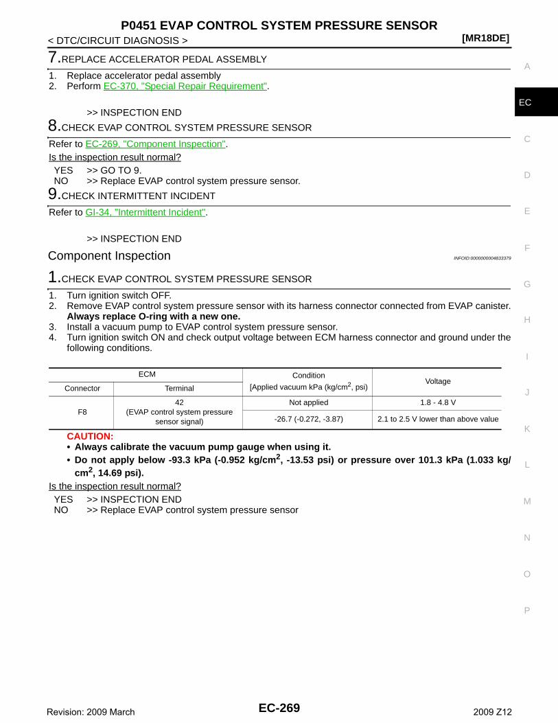
P0451 EVAP CONTROL SYSTEM PRESSURE SENSOR[MR18DE]
C
D
E
F
G
H
I
J
K
L
M
A
C
N
P
O
< DTC/CIRCUIT DIAGNOSIS >
E
7.REPLACE ACCELERATOR PEDAL ASSEMBLY
1. Replace accelerator pedal assembly2. Perform EC-370, "Special Repair Requirement".
>> INSPECTION END
8.CHECK EVAP CONTROL SYSTEM PRESSURE SENSOR
Refer to EC-269, "Component Inspection".Is the inspection result normal?YES >> GO TO 9.NO >> Replace EVAP control system pressure sensor.
9.CHECK INTERMITTENT INCIDENT
Refer to GI-34, "Intermittent Incident".
>> INSPECTION END
Component Inspection INFOID:0000000004833379
1.CHECK EVAP CONTROL SYSTEM PRESSURE SENSOR
1. Turn ignition switch OFF.2. Remove EVAP control system pressure sensor with its harness connector connected from EVAP canister.
Always replace O-ring with a new one.3. Install a vacuum pump to EVAP control system pressure sensor.4. Turn ignition switch ON and check output voltage between ECM harness connector and ground under the
following conditions.
CAUTION:• Always calibrate the vacuum pump gauge when using it.• Do not apply below -93.3 kPa (-0.952 kg/cm2, -13.53 psi) or pressure over 101.3 kPa (1.033 kg/
cm2, 14.69 psi).Is the inspection result normal?YES >> INSPECTION ENDNO >> Replace EVAP control system pressure sensor
ECM Condition
[Applied vacuum kPa (kg/cm2, psi)Voltage
Connector Terminal
F842
(EVAP control system pressure sensor signal)
Not applied 1.8 - 4.8 V
-26.7 (-0.272, -3.87) 2.1 to 2.5 V lower than above value
EC-269Revision: 2009 March 2009 Z12
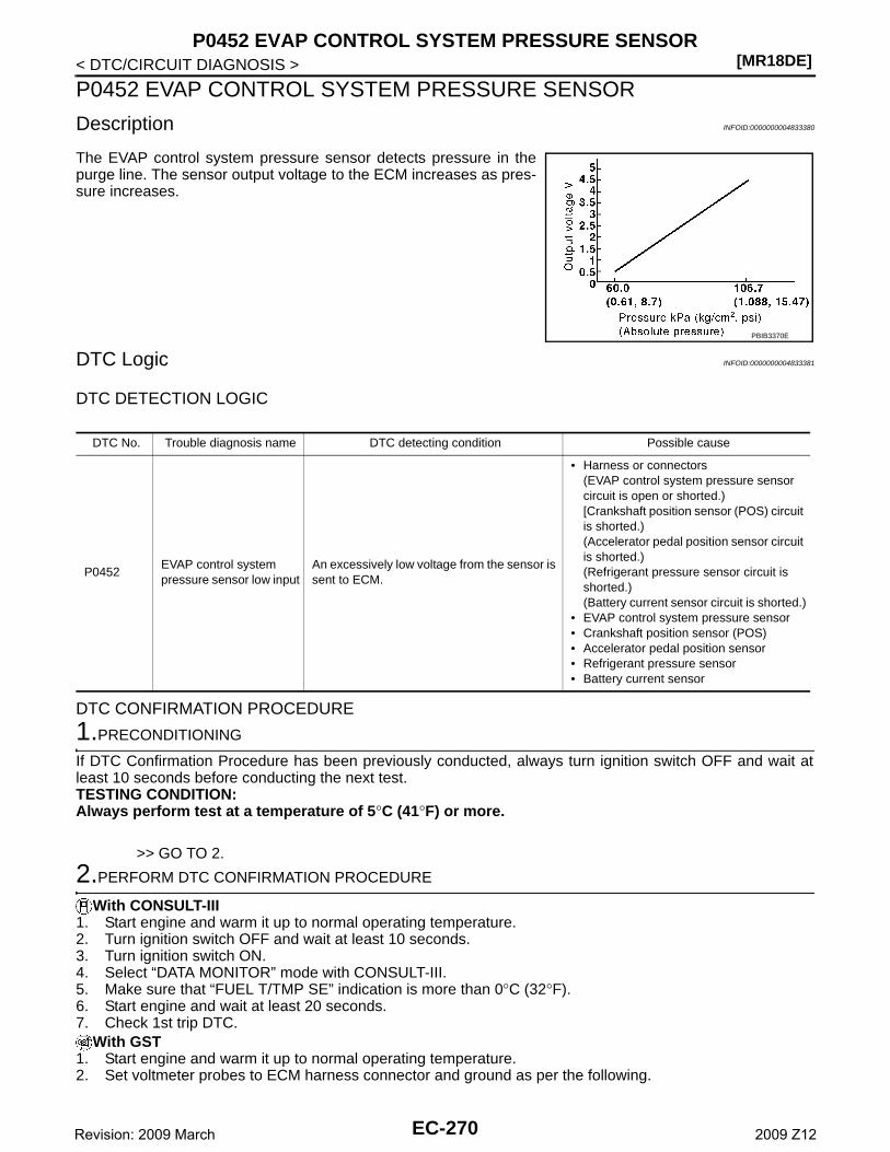
[MR18DE]P0452 EVAP CONTROL SYSTEM PRESSURE SENSOR
< DTC/CIRCUIT DIAGNOSIS >
P0452 EVAP CONTROL SYSTEM PRESSURE SENSOR
Description INFOID:0000000004833380
The EVAP control system pressure sensor detects pressure in thepurge line. The sensor output voltage to the ECM increases as pres-sure increases.
DTC Logic INFOID:0000000004833381
DTC DETECTION LOGIC
DTC CONFIRMATION PROCEDURE
1.PRECONDITIONING
If DTC Confirmation Procedure has been previously conducted, always turn ignition switch OFF and wait atleast 10 seconds before conducting the next test.TESTING CONDITION:Always perform test at a temperature of 5°C (41°F) or more.
>> GO TO 2.
2.PERFORM DTC CONFIRMATION PROCEDURE
With CONSULT-III1. Start engine and warm it up to normal operating temperature.2. Turn ignition switch OFF and wait at least 10 seconds.3. Turn ignition switch ON.4. Select “DATA MONITOR” mode with CONSULT-III.5. Make sure that “FUEL T/TMP SE” indication is more than 0°C (32°F).6. Start engine and wait at least 20 seconds.7. Check 1st trip DTC.
With GST1. Start engine and warm it up to normal operating temperature.2. Set voltmeter probes to ECM harness connector and ground as per the following.
PBIB3370E
DTC No. Trouble diagnosis name DTC detecting condition Possible cause
P0452EVAP control system pressure sensor low input
An excessively low voltage from the sensor is sent to ECM.
• Harness or connectors(EVAP control system pressure sensor circuit is open or shorted.)[Crankshaft position sensor (POS) circuit is shorted.)(Accelerator pedal position sensor circuit is shorted.)(Refrigerant pressure sensor circuit is shorted.)(Battery current sensor circuit is shorted.)
• EVAP control system pressure sensor• Crankshaft position sensor (POS)• Accelerator pedal position sensor• Refrigerant pressure sensor• Battery current sensor
EC-270Revision: 2009 March 2009 Z12
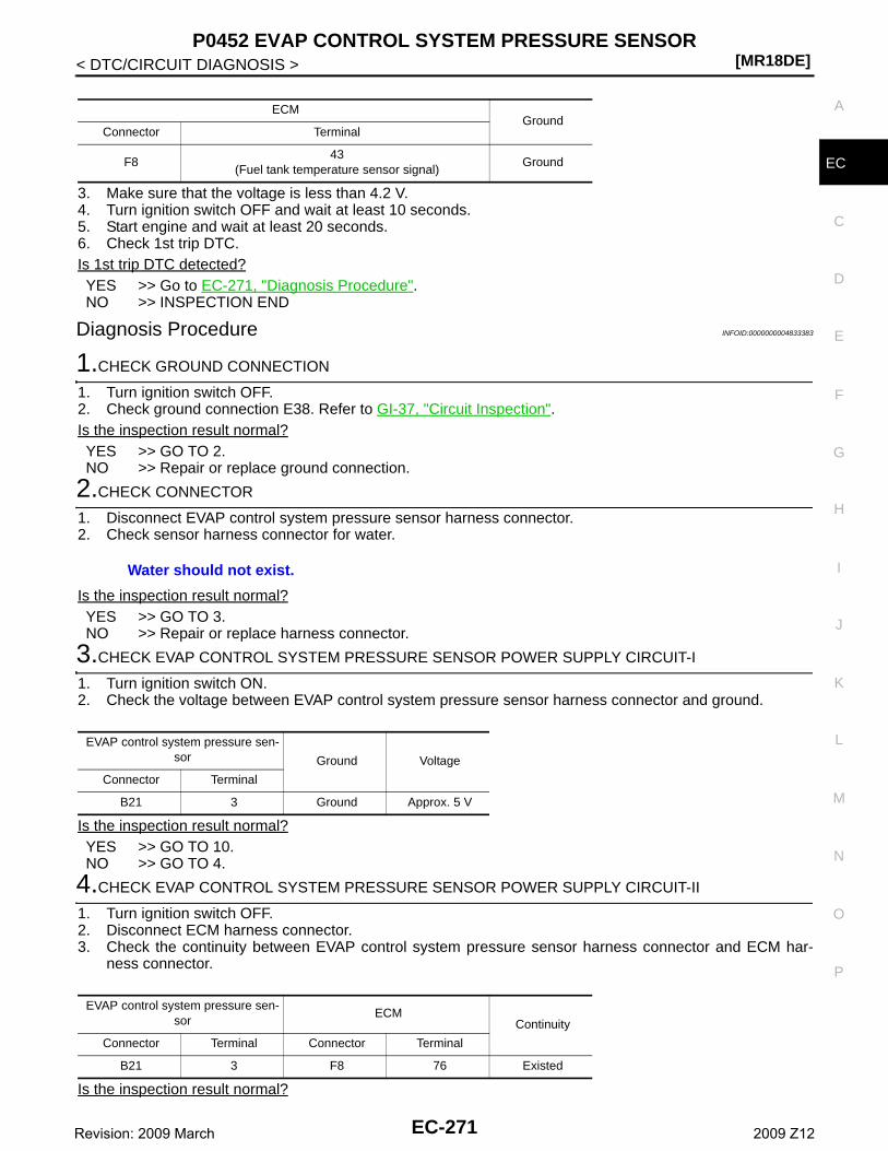
P0452 EVAP CONTROL SYSTEM PRESSURE SENSOR[MR18DE]
C
D
E
F
G
H
I
J
K
L
M
A
C
N
P
O
< DTC/CIRCUIT DIAGNOSIS >
E
3. Make sure that the voltage is less than 4.2 V.4. Turn ignition switch OFF and wait at least 10 seconds.5. Start engine and wait at least 20 seconds.6. Check 1st trip DTC.Is 1st trip DTC detected?YES >> Go to EC-271, "Diagnosis Procedure".NO >> INSPECTION END
Diagnosis Procedure INFOID:0000000004833383
1.CHECK GROUND CONNECTION
1. Turn ignition switch OFF.2. Check ground connection E38. Refer to GI-37, "Circuit Inspection".Is the inspection result normal?YES >> GO TO 2.NO >> Repair or replace ground connection.
2.CHECK CONNECTOR
1. Disconnect EVAP control system pressure sensor harness connector.2. Check sensor harness connector for water.
Is the inspection result normal?YES >> GO TO 3.NO >> Repair or replace harness connector.
3.CHECK EVAP CONTROL SYSTEM PRESSURE SENSOR POWER SUPPLY CIRCUIT-I
1. Turn ignition switch ON.2. Check the voltage between EVAP control system pressure sensor harness connector and ground.
Is the inspection result normal?YES >> GO TO 10.NO >> GO TO 4.
4.CHECK EVAP CONTROL SYSTEM PRESSURE SENSOR POWER SUPPLY CIRCUIT-II
1. Turn ignition switch OFF.2. Disconnect ECM harness connector.3. Check the continuity between EVAP control system pressure sensor harness connector and ECM har-
ness connector.
Is the inspection result normal?
ECMGround
Connector Terminal
F843
(Fuel tank temperature sensor signal)Ground
Water should not exist.
EVAP control system pressure sen-sor Ground Voltage
Connector Terminal
B21 3 Ground Approx. 5 V
EVAP control system pressure sen-sor
ECMContinuity
Connector Terminal Connector Terminal
B21 3 F8 76 Existed
EC-271Revision: 2009 March 2009 Z12
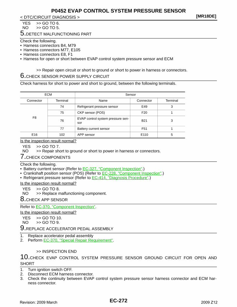
[MR18DE]P0452 EVAP CONTROL SYSTEM PRESSURE SENSOR
< DTC/CIRCUIT DIAGNOSIS >YES >> GO TO 6.NO >> GO TO 5.
5.DETECT MALFUNCTIONING PART
Check the following.• Harness connectors B4, M79• Harness connectors M77, E105• Harness connectors E8, F1• Harness for open or short between EVAP control system pressure sensor and ECM
>> Repair open circuit or short to ground or short to power in harness or connectors.
6.CHECK SENSOR POWER SUPPLY CIRCUIT
Check harness for short to power and short to ground, between the following terminals.
Is the inspection result normal?YES >> GO TO 7.NO >> Repair short to ground or short to power in harness or connectors.
7.CHECK COMPONENTS
Check the following.• Battery currtent sensor (Refer to EC-327, "Component Inspection".)• Crankshaft position sensor (POS) (Refer to EC-228, "Component Inspection".)• Refrigerant pressure sensor (Refer to EC-414, "Diagnosis Procedure".)Is the inspection result normal?YES >> GO TO 8.NO >> Replace malfunctioning component.
8.CHECK APP SENSOR
Refer to EC-370, "Component Inspection".Is the inspection result normal?YES >> GO TO 10.NO >> GO TO 9.
9.REPLACE ACCELERATOR PEDAL ASSEMBLY
1. Replace accelerator pedal assembly2. Perform EC-370, "Special Repair Requirement".
>> INSPECTION END
10.CHECK EVAP CONTROL SYSTEM PRESSURE SENSOR GROUND CIRCUIT FOR OPEN ANDSHORT
1. Turn ignition switch OFF.2. Disconnect ECM harness connector.3. Check the continuity between EVAP control system pressure sensor harness connector and ECM har-
ness connector.
ECM Sensor
Connector Terminal Name Connector Terminal
F8
74 Refrigerant pressure sensor E49 3
75 CKP sensor (POS) F20 1
76EVAP control system pressure sen-sor
B21 3
77 Battery current sensor F51 1
E16 102 APP sensor E110 5
EC-272Revision: 2009 March 2009 Z12
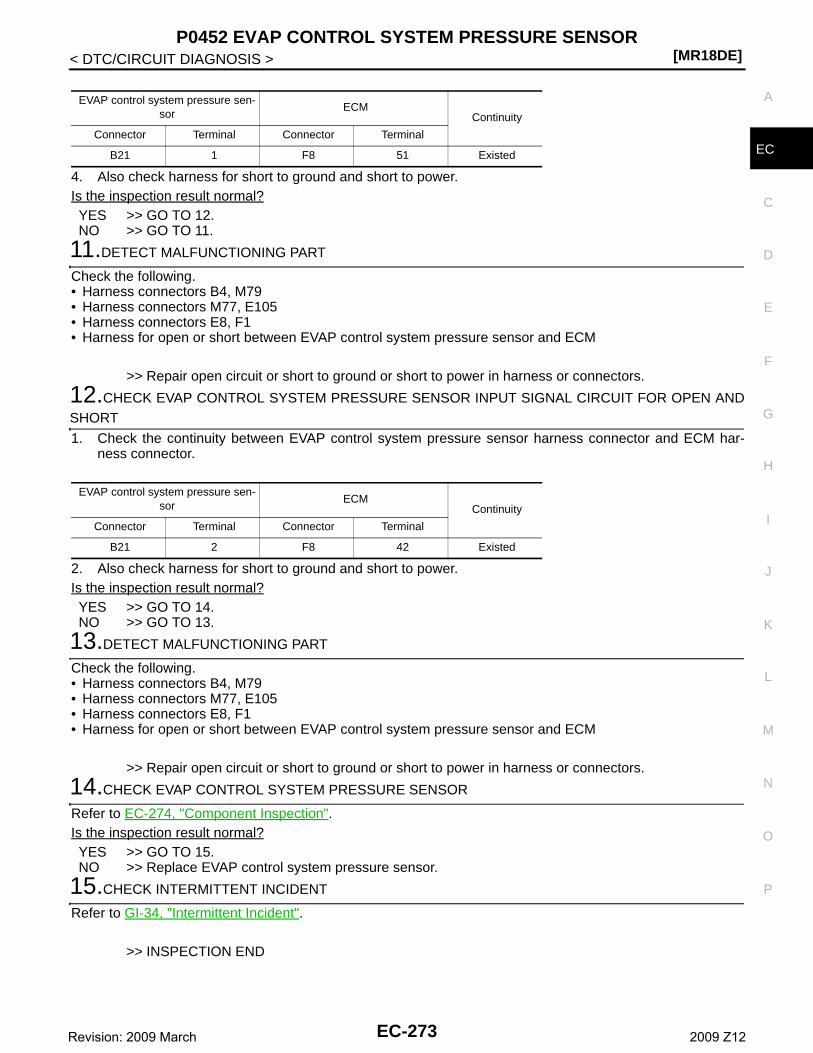
P0452 EVAP CONTROL SYSTEM PRESSURE SENSOR[MR18DE]
C
D
E
F
G
H
I
J
K
L
M
A
C
N
P
O
< DTC/CIRCUIT DIAGNOSIS >
E
4. Also check harness for short to ground and short to power.Is the inspection result normal?YES >> GO TO 12.NO >> GO TO 11.
11.DETECT MALFUNCTIONING PART
Check the following.• Harness connectors B4, M79• Harness connectors M77, E105• Harness connectors E8, F1• Harness for open or short between EVAP control system pressure sensor and ECM
>> Repair open circuit or short to ground or short to power in harness or connectors.
12.CHECK EVAP CONTROL SYSTEM PRESSURE SENSOR INPUT SIGNAL CIRCUIT FOR OPEN ANDSHORT
1. Check the continuity between EVAP control system pressure sensor harness connector and ECM har-ness connector.
2. Also check harness for short to ground and short to power.Is the inspection result normal?YES >> GO TO 14.NO >> GO TO 13.
13.DETECT MALFUNCTIONING PART
Check the following.• Harness connectors B4, M79• Harness connectors M77, E105• Harness connectors E8, F1• Harness for open or short between EVAP control system pressure sensor and ECM
>> Repair open circuit or short to ground or short to power in harness or connectors.
14.CHECK EVAP CONTROL SYSTEM PRESSURE SENSOR
Refer to EC-274, "Component Inspection".Is the inspection result normal?YES >> GO TO 15.NO >> Replace EVAP control system pressure sensor.
15.CHECK INTERMITTENT INCIDENT
Refer to GI-34, "Intermittent Incident".
>> INSPECTION END
EVAP control system pressure sen-sor
ECMContinuity
Connector Terminal Connector Terminal
B21 1 F8 51 Existed
EVAP control system pressure sen-sor
ECMContinuity
Connector Terminal Connector Terminal
B21 2 F8 42 Existed
EC-273Revision: 2009 March 2009 Z12
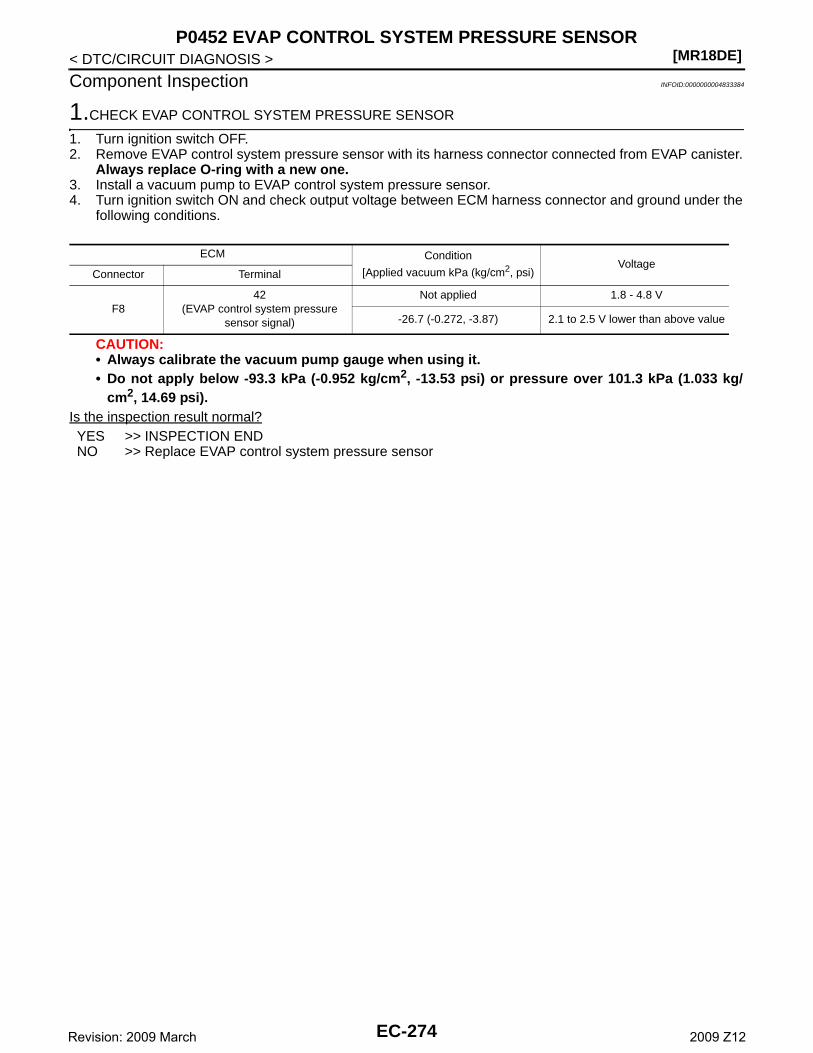
[MR18DE]P0452 EVAP CONTROL SYSTEM PRESSURE SENSOR
< DTC/CIRCUIT DIAGNOSIS >
Component Inspection INFOID:0000000004833384
1.CHECK EVAP CONTROL SYSTEM PRESSURE SENSOR
1. Turn ignition switch OFF.2. Remove EVAP control system pressure sensor with its harness connector connected from EVAP canister.
Always replace O-ring with a new one.3. Install a vacuum pump to EVAP control system pressure sensor.4. Turn ignition switch ON and check output voltage between ECM harness connector and ground under the
following conditions.
CAUTION:• Always calibrate the vacuum pump gauge when using it.• Do not apply below -93.3 kPa (-0.952 kg/cm2, -13.53 psi) or pressure over 101.3 kPa (1.033 kg/
cm2, 14.69 psi).Is the inspection result normal?YES >> INSPECTION ENDNO >> Replace EVAP control system pressure sensor
ECM Condition
[Applied vacuum kPa (kg/cm2, psi)Voltage
Connector Terminal
F842
(EVAP control system pressure sensor signal)
Not applied 1.8 - 4.8 V
-26.7 (-0.272, -3.87) 2.1 to 2.5 V lower than above value
EC-274Revision: 2009 March 2009 Z12
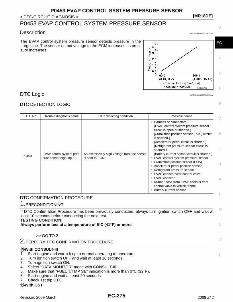
P0453 EVAP CONTROL SYSTEM PRESSURE SENSOR[MR18DE]
C
D
E
F
G
H
I
J
K
L
M
A
C
N
P
O
< DTC/CIRCUIT DIAGNOSIS >
E
P0453 EVAP CONTROL SYSTEM PRESSURE SENSOR
Description INFOID:0000000004833385
The EVAP control system pressure sensor detects pressure in thepurge line. The sensor output voltage to the ECM increases as pres-sure increases.
DTC Logic INFOID:0000000004833386
DTC DETECTION LOGIC
DTC CONFIRMATION PROCEDURE
1.PRECONDITIONING
If DTC Confirmation Procedure has been previously conducted, always turn ignition switch OFF and wait atleast 10 seconds before conducting the next test.TESTING CONDITION:Always perform test at a temperature of 5°C (41°F) or more.
>> GO TO 2.
2.PERFORM DTC CONFIRMATION PROCEDURE
With CONSULT-III1. Start engine and warm it up to normal operating temperature.2. Turn ignition switch OFF and wait at least 10 seconds.3. Turn ignition switch ON.4. Select “DATA MONITOR” mode with CONSULT-III.5. Make sure that “FUEL T/TMP SE” indication is more than 0°C (32°F).6. Start engine and wait at least 20 seconds.7. Check 1st trip DTC.
With GST
PBIB3370E
DTC No. Trouble diagnosis name DTC detecting condition Possible cause
P0453EVAP control system pres-sure sensor high input
An excessively high voltage from the sensor is sent to ECM.
• Harness or connectors(EVAP control system pressure sensor circuit is open or shorted.)[Crankshaft position sensor (POS) circuit is shorted.](Accelerator pedal circuit is shorted.)(Refrigerant pressure sensor circuit is shorted.)(Battery current sensor circuit is shorted.)
• EVAP control system pressure sensor• Crankshaft position sensor (POS)• Accelerator pedal position sensor• Refrigerant pressure sensor• EVAP canister vent control valve• EVAP canister• Rubber hose from EVAP canister vent
control valve to vehicle frame• Battery current sensor
EC-275Revision: 2009 March 2009 Z12
[MR18DE]P0453 EVAP CONTROL SYSTEM PRESSURE SENSOR
< DTC/CIRCUIT DIAGNOSIS >1. Start engine and warm it up to normal operating temperature.2. Set voltmeter probes to ECM harness connector and ground as per the following.
3. Make sure that the voltage is less than 4.2 V.4. Turn ignition switch OFF and wait at least 10 seconds.5. Start engine and wait at least 20 seconds.6. Check 1st trip DTC.Is 1st trip DTC detected?YES >> Go to EC-276, "Diagnosis Procedure".NO >> INSPECTION END
Diagnosis Procedure INFOID:0000000004833388
1.CHECK GROUND CONNECTION
1. Turn ignition switch OFF.2. Check ground connection E38. Refer to GI-37, "Circuit Inspection".Is the inspection result normal?YES >> GO TO 2.NO >> Repair or replace ground connection.
2.CHECK CONNECTOR
1. Disconnect EVAP control system pressure sensor harness connector.2. Check sensor harness connector for water.
Is the inspection result normal?YES >> GO TO 3.NO >> Repair or replace harness connector.
3.CHECK EVAP CONTROL SYSTEM PRESSURE SENSOR POWER SUPPLY CIRCUIT
1. Turn ignition switch ON.2. Check the voltage between EVAP control system pressure sensor harness connector and ground.
Is the inspection result normal?YES >> GO TO 10.NO >> GO TO 4.
4.CHECK EVAP CONTROL SYSTEM PRESSURE SENSOR POWER SUPPLY CIRCUIT-II
1. Turn ignition switch OFF.2. Disconnect ECM harness connector.3. Check the continuity between EVAP control system pressure sensor harness connector and ECM har-
ness connector.
ECMGround
Connector Terminal
F843
(Fuel tank temperature sensor signal)Ground
Water should not exist.
EVAP control system pressure sen-sor Ground Voltage
Connector Terminal
B21 3 Ground Approx. 5 V
EC-276Revision: 2009 March 2009 Z12
P0453 EVAP CONTROL SYSTEM PRESSURE SENSOR[MR18DE]
C
D
E
F
G
H
I
J
K
L
M
A
C
N
P
O
< DTC/CIRCUIT DIAGNOSIS >
E
Is the inspection result normal?YES >> GO TO 6.NO >> GO TO 5.
5.DETECT MALFUNCTIONING PART
Check the following.• Harness connectors B4, M79• Harness connectors M77, E105• Harness connectors E8, F1• Harness for open or short between EVAP control system pressure sensor and ECM
>> Repair open circuit or short to ground or short to power in harness or connectors.
6.CHECK SENSOR POWER SUPPLY CIRCUIT
Check harness for short to power and short to ground, between the following terminals.
Is the inspection result normal?YES >> GO TO 7.NO >> Repair short to ground or short to power in harness or connectors.
7.CHECK COMPONENTS
Check the following.• Battery currentsensor (Refer to EC-327, "Component Inspection".)• Crankshaft position sensor (POS) (Refer to EC-228, "Component Inspection".)• Refrigerant pressure sensor (Refer to EC-414, "Diagnosis Procedure".)Is the inspection result normal?YES >> GO TO 8.NO >> Replace malfunctioning component.
8.CHECK APP SENSOR
Refer to EC-370, "Component Inspection".Is the inspection result normal?YES >> GO TO 10.NO >> GO TO 9.
9.REPLACE ACCELERATOR PEDAL ASSEMBLY
1. Replace accelerator pedal assembly2. Perform EC-370, "Special Repair Requirement".
>> INSPECTION END
10.CHECK EVAP CONTROL SYSTEM PRESSURE SENSOR GROUND CIRCUIT FOR OPEN AND
EVAP control system pressure sen-sor
ECMContinuity
Connector Terminal Connector Terminal
B21 3 F8 76 Existed
ECM Sensor
Connector Terminal Name Connector Terminal
F8
74 Refrigerant pressure sensor E49 3
75 CKP sensor (POS) F20 1
76EVAP control system pressure sen-sor
B21 3
77 Battery current sensor F51 1
E16 102 APP sensor E110 5
EC-277Revision: 2009 March 2009 Z12
[MR18DE]P0453 EVAP CONTROL SYSTEM PRESSURE SENSOR
< DTC/CIRCUIT DIAGNOSIS >SHORT
1. Turn ignition switch OFF.2. Disconnect ECM harness connector.3. Check the continuity between EVAP control system pressure sensor harness connector and ECM har-
ness connector.
4. Also check harness for short to ground and short to power.Is the inspection result normal?YES >> GO TO 12.NO >> GO TO 11.
11.DETECT MALFUNCTIONING PART
Check the following.• Harness connectors B4, M79• Harness connectors M77, E105• Harness connectors E8, F1• Harness for open or short between EVAP control system pressure sensor and ECM
>> Repair open circuit or short to ground or short to power in harness or connectors.
12.CHECK EVAP CONTROL SYSTEM PRESSURE SENSOR INPUT SIGNAL CIRCUIT FOR OPEN ANDSHORT
1. Check the continuity between EVAP control system pressure sensor harness connector and ECM har-ness connector.
2. Also check harness for short to ground and short to power.Is the inspection result normal?YES >> GO TO 14.NO >> GO TO 13.
13.DETECT MALFUNCTIONING PART
Check the following.• Harness connectors B4, M79• Harness connectors M77, E105• Harness connectors E8, F1• Harness for open or short between EVAP control system pressure sensor and ECM
>> Repair open circuit or short to ground or short to power in harness or connectors.
14.CHECK RUBBER TUBE
1. Disconnect rubber tube connected to EVAP canister vent control valve.2. Check the rubber tube for clogging.Is the inspection result normal?YES >> GO TO 15.NO >> Clean the rubber tube using an air blower, repair or replace rubber tube.
15.CHECK EVAP CANISTER VENT CONTROL VALVE
EVAP control system pressure sen-sor
ECMContinuity
Connector Terminal Connector Terminal
B21 1 F8 51 Existed
EVAP control system pressure sen-sor
ECMContinuity
Connector Terminal Connector Terminal
B21 2 F8 42 Existed
EC-278Revision: 2009 March 2009 Z12
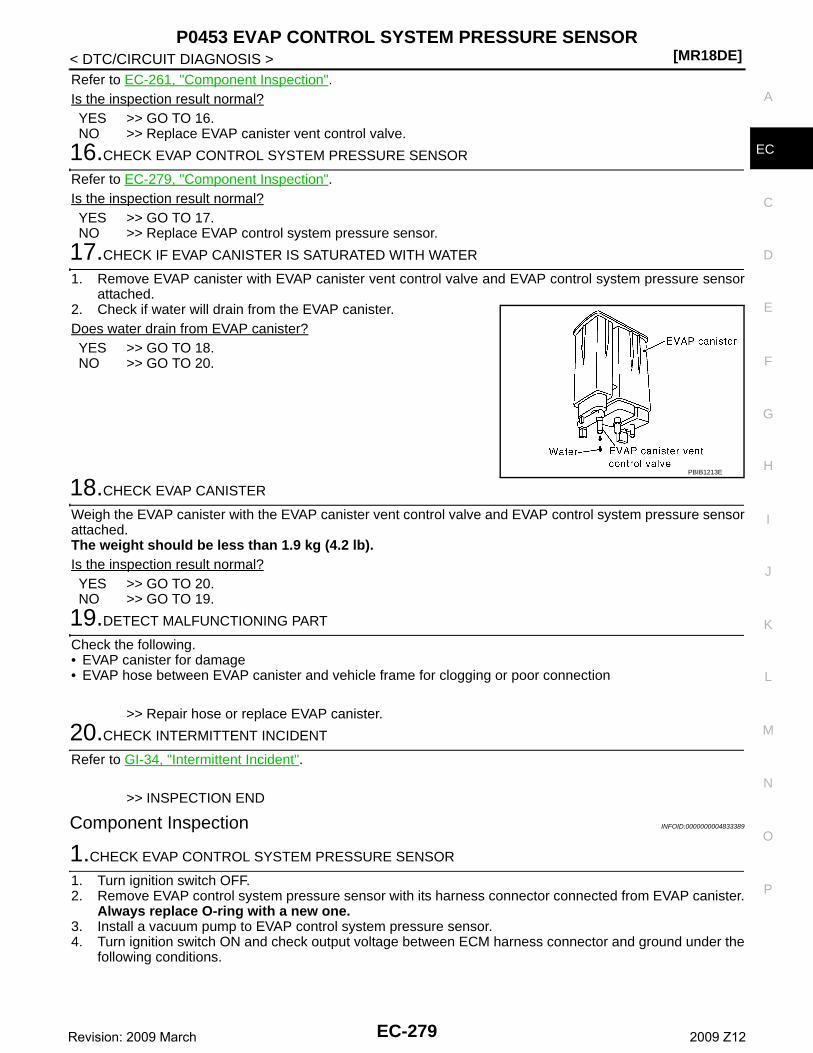
P0453 EVAP CONTROL SYSTEM PRESSURE SENSOR[MR18DE]
C
D
E
F
G
H
I
J
K
L
M
A
C
N
P
O
< DTC/CIRCUIT DIAGNOSIS >
E
Refer to EC-261, "Component Inspection".Is the inspection result normal?YES >> GO TO 16.NO >> Replace EVAP canister vent control valve.
16.CHECK EVAP CONTROL SYSTEM PRESSURE SENSOR
Refer to EC-279, "Component Inspection".Is the inspection result normal?YES >> GO TO 17.NO >> Replace EVAP control system pressure sensor.
17.CHECK IF EVAP CANISTER IS SATURATED WITH WATER
1. Remove EVAP canister with EVAP canister vent control valve and EVAP control system pressure sensorattached.
2. Check if water will drain from the EVAP canister.Does water drain from EVAP canister?YES >> GO TO 18.NO >> GO TO 20.
18.CHECK EVAP CANISTER
Weigh the EVAP canister with the EVAP canister vent control valve and EVAP control system pressure sensorattached.The weight should be less than 1.9 kg (4.2 lb).Is the inspection result normal?YES >> GO TO 20.NO >> GO TO 19.
19.DETECT MALFUNCTIONING PART
Check the following.• EVAP canister for damage• EVAP hose between EVAP canister and vehicle frame for clogging or poor connection
>> Repair hose or replace EVAP canister.
20.CHECK INTERMITTENT INCIDENT
Refer to GI-34, "Intermittent Incident".
>> INSPECTION END
Component Inspection INFOID:0000000004833389
1.CHECK EVAP CONTROL SYSTEM PRESSURE SENSOR
1. Turn ignition switch OFF.2. Remove EVAP control system pressure sensor with its harness connector connected from EVAP canister.
Always replace O-ring with a new one.3. Install a vacuum pump to EVAP control system pressure sensor.4. Turn ignition switch ON and check output voltage between ECM harness connector and ground under the
following conditions.
PBIB1213E
EC-279Revision: 2009 March 2009 Z12
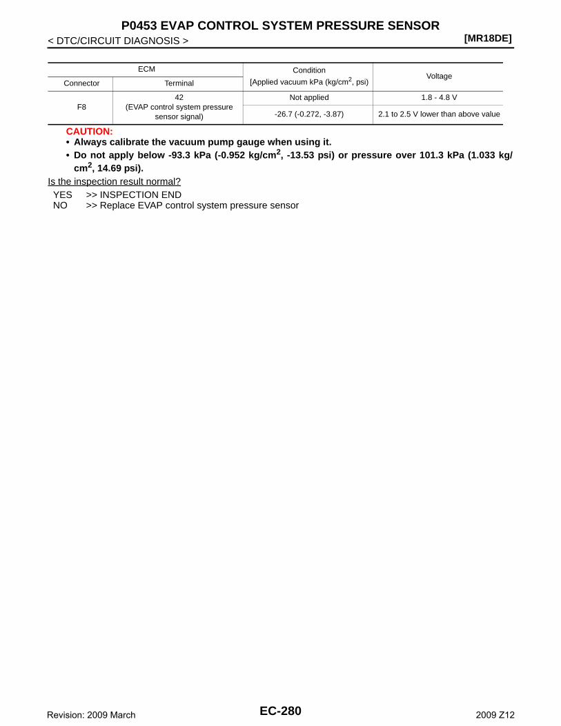
[MR18DE]P0453 EVAP CONTROL SYSTEM PRESSURE SENSOR
< DTC/CIRCUIT DIAGNOSIS >
CAUTION:• Always calibrate the vacuum pump gauge when using it.• Do not apply below -93.3 kPa (-0.952 kg/cm2, -13.53 psi) or pressure over 101.3 kPa (1.033 kg/
cm2, 14.69 psi).Is the inspection result normal?YES >> INSPECTION ENDNO >> Replace EVAP control system pressure sensor
ECM Condition
[Applied vacuum kPa (kg/cm2, psi)Voltage
Connector Terminal
F842
(EVAP control system pressure sensor signal)
Not applied 1.8 - 4.8 V
-26.7 (-0.272, -3.87) 2.1 to 2.5 V lower than above value
EC-280Revision: 2009 March 2009 Z12
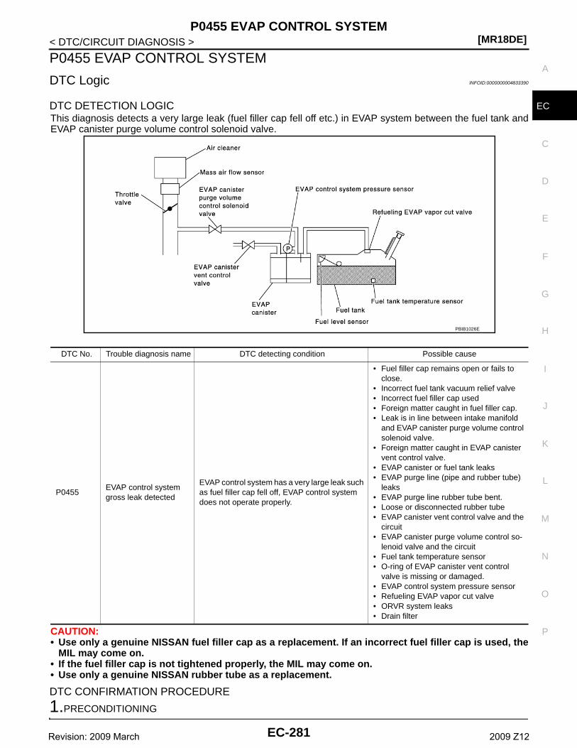
P0455 EVAP CONTROL SYSTEM[MR18DE]
C
D
E
F
G
H
I
J
K
L
M
A
C
N
P
O
< DTC/CIRCUIT DIAGNOSIS >
E
P0455 EVAP CONTROL SYSTEM
DTC Logic INFOID:0000000004833390
DTC DETECTION LOGICThis diagnosis detects a very large leak (fuel filler cap fell off etc.) in EVAP system between the fuel tank andEVAP canister purge volume control solenoid valve.
CAUTION:• Use only a genuine NISSAN fuel filler cap as a replacement. If an incorrect fuel filler cap is used, the
MIL may come on.• If the fuel filler cap is not tightened properly, the MIL may come on.• Use only a genuine NISSAN rubber tube as a replacement.
DTC CONFIRMATION PROCEDURE
1.PRECONDITIONING
DTC No. Trouble diagnosis name DTC detecting condition Possible cause
P0455EVAP control system gross leak detected
EVAP control system has a very large leak such as fuel filler cap fell off, EVAP control system does not operate properly.
• Fuel filler cap remains open or fails to close.
• Incorrect fuel tank vacuum relief valve• Incorrect fuel filler cap used• Foreign matter caught in fuel filler cap.• Leak is in line between intake manifold
and EVAP canister purge volume control solenoid valve.
• Foreign matter caught in EVAP canister vent control valve.
• EVAP canister or fuel tank leaks• EVAP purge line (pipe and rubber tube)
leaks• EVAP purge line rubber tube bent.• Loose or disconnected rubber tube• EVAP canister vent control valve and the
circuit• EVAP canister purge volume control so-
lenoid valve and the circuit• Fuel tank temperature sensor• O-ring of EVAP canister vent control
valve is missing or damaged.• EVAP control system pressure sensor• Refueling EVAP vapor cut valve• ORVR system leaks• Drain filter
PBIB1026E
EC-281Revision: 2009 March 2009 Z12
[MR18DE]P0455 EVAP CONTROL SYSTEM
< DTC/CIRCUIT DIAGNOSIS >CAUTION:Never remove fuel filler cap during the DTC CONFIRMATION PROCEDURE.If DTC Confirmation Procedure has been previously conducted, always turn ignition switch OFF and wait atleast 10 seconds before conducting the next test.NOTE:Make sure that EVAP hoses are connected to EVAP canister purge volume control solenoid valveproperly.TESTING CONDITION:• Perform “DTC WORK SUPPORT” when the fuel level is between 1/4 and 3/4 full, and vehicle is placed
on flat level surface.• Open engine hood before conducting the following procedures.Do you have CONSULT-III?YES >> GO TO 2.NO >> GO TO 4.
2.PERFORM DTC CONFIRMATION PROCEDURE
With CONSULT-III1. Tighten fuel filler cap securely until ratcheting sound is heard.2. Turn ignition switch ON.3. Turn ignition switch OFF and wait at least 10 seconds.4. Turn ignition switch ON and select “DATA MONITOR” mode with CONSULT-III.5. Make sure that the following conditions are met.
COOLAN TEMP/S: 0 - 100°C (32 - 212°F)INT/A TEMP SE: 0 - 60°C (32 - 140°F)
6. Select “EVAP SML LEAK P0442/P1442” of “EVAPORATIVE SYSTEM” in “DTC WORK SUPPORT” modewith CONSULT-III.Follow the instruction displayed.NOTE:If the engine speed cannot be maintained within the range displayed on the CONSULT-III screen, go toEC-12, "BASIC INSPECTION : Special Repair Requirement".
Which is displayed on CONSULT-III screen?OK >> INSPECTION ENDNG >> GO TO 3.
3.CHECK DTC
Check DTC.Which DTC is detected?P0455 >> Go to EC-282, "Diagnosis Procedure".P0442 >> Go to EC-245, "Diagnosis Procedure".
4.PERFORM DTC CONFIRMATION PROCEDURE
With GSTNOTE:Be sure to read the explanation of DIRVING PATTERN in EC-451, "How to Set SRT Code" before drivingvehicle.1. Start engine.2. Drive vehicle according to DRIVING PATTERN.3. Stop vehicle.4. Turn ignition switch OFF, wait at least 10 seconds and then turn ON.5. Check 1st trip DTC.Is 1st trip DTC detected?YES-1 >> P0455: Go to EC-282, "Diagnosis Procedure".YES-2 >> P0442: Go to EC-245, "Diagnosis Procedure".YES-3 >> P0441: Go to EC-240, "Diagnosis Procedure".NO >> INSPECTION END
Diagnosis Procedure INFOID:0000000004833391
1.CHECK FUEL FILLER CAP DESIGN
EC-282Revision: 2009 March 2009 Z12
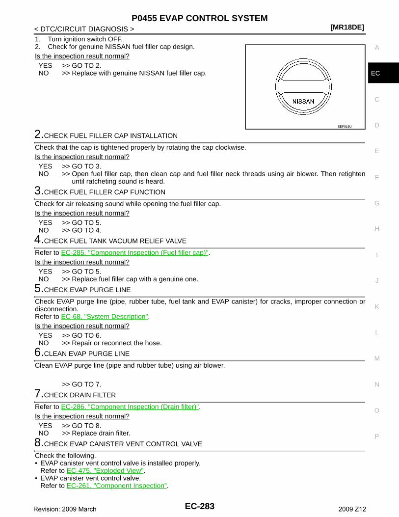
P0455 EVAP CONTROL SYSTEM[MR18DE]
C
D
E
F
G
H
I
J
K
L
M
A
C
N
P
O
< DTC/CIRCUIT DIAGNOSIS >
E
1. Turn ignition switch OFF.2. Check for genuine NISSAN fuel filler cap design.Is the inspection result normal?YES >> GO TO 2.NO >> Replace with genuine NISSAN fuel filler cap.
2.CHECK FUEL FILLER CAP INSTALLATION
Check that the cap is tightened properly by rotating the cap clockwise.Is the inspection result normal?YES >> GO TO 3.NO >> Open fuel filler cap, then clean cap and fuel filler neck threads using air blower. Then retighten
until ratcheting sound is heard.
3.CHECK FUEL FILLER CAP FUNCTION
Check for air releasing sound while opening the fuel filler cap.Is the inspection result normal?YES >> GO TO 5.NO >> GO TO 4.
4.CHECK FUEL TANK VACUUM RELIEF VALVE
Refer to EC-285, "Component Inspection (Fuel filler cap)".Is the inspection result normal?YES >> GO TO 5.NO >> Replace fuel filler cap with a genuine one.
5.CHECK EVAP PURGE LINE
Check EVAP purge line (pipe, rubber tube, fuel tank and EVAP canister) for cracks, improper connection ordisconnection.Refer to EC-68, "System Description".Is the inspection result normal?YES >> GO TO 6.NO >> Repair or reconnect the hose.
6.CLEAN EVAP PURGE LINE
Clean EVAP purge line (pipe and rubber tube) using air blower.
>> GO TO 7.
7.CHECK DRAIN FILTER
Refer to EC-286, "Component Inspection (Drain filter)".Is the inspection result normal?YES >> GO TO 8.NO >> Replace drain filter.
8.CHECK EVAP CANISTER VENT CONTROL VALVE
Check the following.• EVAP canister vent control valve is installed properly.
Refer to EC-475, "Exploded View".• EVAP canister vent control valve.
Refer to EC-261, "Component Inspection".
SEF915U
EC-283Revision: 2009 March 2009 Z12
[MR18DE]P0455 EVAP CONTROL SYSTEM
< DTC/CIRCUIT DIAGNOSIS >Is the inspection result normal?YES >> GO TO 9.NO >> Repair or replace EVAP canister vent control valve and O-ring.
9.CHECK FOR EVAP LEAK
Refer to EC-473, "Inspection".Is there any leak in EVAP line?YES >> Repair or replace.NO-1 >> With CONSULT-III: GO TO 10.NO-2 >> Without CONSULT-III: GO TO 11.
10.CHECK EVAP CANISTER PURGE VOLUME CONTROL SOLENOID VALVE OPERATION
With CONSULT-III1. Disconnect vacuum hose to EVAP canister purge volume control solenoid valve at EVAP service port.2. Start engine.3. Perform “PURG VOL CONT/V” in “ACTIVE TEST” mode.4. Touch “Qu” on CONSULT-III screen to increase “PURG VOL C/V” opening to 100%.5. Check vacuum hose for vacuum.
Is the inspection result normal?YES >> GO TO 13.NO >> GO TO 12.
11.CHECK EVAP CANISTER PURGE VOLUME CONTROL SOLENOID VALVE OPERATION
Without CONSULT-III1. Start engine and warm it up to normal operating temperature.2. Stop engine.3. Disconnect vacuum hose to EVAP canister purge volume control solenoid valve at EVAP service port.4. Start engine and let it idle for at least 80 seconds.5. Check vacuum hose for vacuum when revving engine up to 2,000 rpm.
Is the inspection result normal?YES >> GO TO 14.NO >> GO TO 12.
12.CHECK VACUUM HOSE
Check vacuum hoses for clogging or disconnection. Refer to EC-68, "System Description".Is the inspection result normal?YES-1 >> With CONSULT-III: GO TO 13.YES-2 >> Without CONSULT-III: GO TO 14.NO >> Repair or reconnect the hose.
13.CHECK EVAP CANISTER PURGE VOLUME CONTROL SOLENOID VALVE
With CONSULT-III1. Start engine.2. Perform “PURG VOL CONT/V” in “ACTIVE TEST” mode with CONSULT-III. Check that engine speed var-
ies according to the valve opening.Does engine speed vary according to the valve opening?YES >> GO TO 15.NO >> GO TO 14.
14.CHECK EVAP CANISTER PURGE VOLUME CONTROL SOLENOID VALVE
Refer to EC-254, "Component Inspection".Is the inspection result normal?YES >> GO TO 15.
Vacuum should exist.
Vacuum should exist.
EC-284Revision: 2009 March 2009 Z12
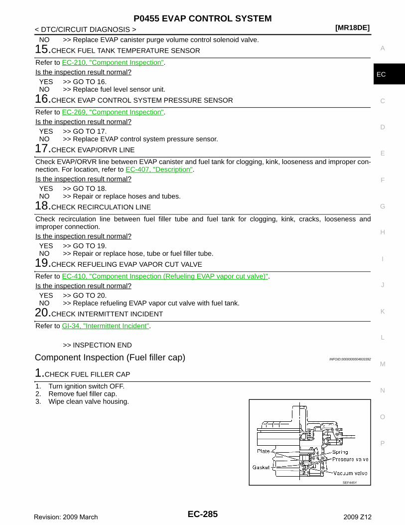
P0455 EVAP CONTROL SYSTEM[MR18DE]
C
D
E
F
G
H
I
J
K
L
M
A
C
N
P
O
< DTC/CIRCUIT DIAGNOSIS >
E
NO >> Replace EVAP canister purge volume control solenoid valve.
15.CHECK FUEL TANK TEMPERATURE SENSOR
Refer to EC-210, "Component Inspection".Is the inspection result normal?YES >> GO TO 16.NO >> Replace fuel level sensor unit.
16.CHECK EVAP CONTROL SYSTEM PRESSURE SENSOR
Refer to EC-269, "Component Inspection".Is the inspection result normal?YES >> GO TO 17.NO >> Replace EVAP control system pressure sensor.
17.CHECK EVAP/ORVR LINE
Check EVAP/ORVR line between EVAP canister and fuel tank for clogging, kink, looseness and improper con-nection. For location, refer to EC-407, "Description".Is the inspection result normal?YES >> GO TO 18.NO >> Repair or replace hoses and tubes.
18.CHECK RECIRCULATION LINE
Check recirculation line between fuel filler tube and fuel tank for clogging, kink, cracks, looseness andimproper connection.Is the inspection result normal?YES >> GO TO 19.NO >> Repair or replace hose, tube or fuel filler tube.
19.CHECK REFUELING EVAP VAPOR CUT VALVE
Refer to EC-410, "Component Inspection (Refueling EVAP vapor cut valve)".Is the inspection result normal?YES >> GO TO 20.NO >> Replace refueling EVAP vapor cut valve with fuel tank.
20.CHECK INTERMITTENT INCIDENT
Refer to GI-34, "Intermittent Incident".
>> INSPECTION END
Component Inspection (Fuel filler cap) INFOID:0000000004833392
1.CHECK FUEL FILLER CAP
1. Turn ignition switch OFF.2. Remove fuel filler cap.3. Wipe clean valve housing.
SEF445Y
EC-285Revision: 2009 March 2009 Z12
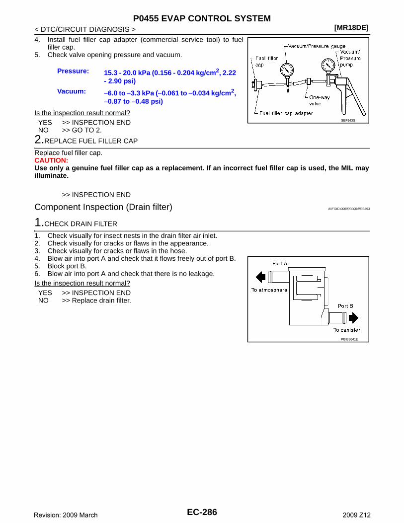
[MR18DE]P0455 EVAP CONTROL SYSTEM
< DTC/CIRCUIT DIAGNOSIS >4. Install fuel filler cap adapter (commercial service tool) to fuel
filler cap.5. Check valve opening pressure and vacuum.
Is the inspection result normal?YES >> INSPECTION ENDNO >> GO TO 2.
2.REPLACE FUEL FILLER CAP
Replace fuel filler cap.CAUTION:Use only a genuine fuel filler cap as a replacement. If an incorrect fuel filler cap is used, the MIL mayilluminate.
>> INSPECTION END
Component Inspection (Drain filter) INFOID:0000000004833393
1.CHECK DRAIN FILTER
1. Check visually for insect nests in the drain filter air inlet.2. Check visually for cracks or flaws in the appearance.3. Check visually for cracks or flaws in the hose.4. Blow air into port A and check that it flows freely out of port B.5. Block port B.6. Blow air into port A and check that there is no leakage.Is the inspection result normal?YES >> INSPECTION ENDNO >> Replace drain filter.
Pressure: 15.3 - 20.0 kPa (0.156 - 0.204 kg/cm2, 2.22 - 2.90 psi)
Vacuum: −6.0 to −3.3 kPa (−0.061 to −0.034 kg/cm2, −0.87 to −0.48 psi)
SEF943S
PBIB3641E
EC-286Revision: 2009 March 2009 Z12
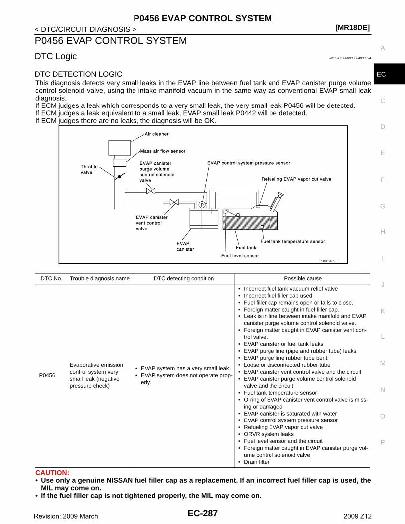
P0456 EVAP CONTROL SYSTEM[MR18DE]
C
D
E
F
G
H
I
J
K
L
M
A
C
N
P
O
< DTC/CIRCUIT DIAGNOSIS >
E
P0456 EVAP CONTROL SYSTEM
DTC Logic INFOID:0000000004833394
DTC DETECTION LOGICThis diagnosis detects very small leaks in the EVAP line between fuel tank and EVAP canister purge volumecontrol solenoid valve, using the intake manifold vacuum in the same way as conventional EVAP small leakdiagnosis.If ECM judges a leak which corresponds to a very small leak, the very small leak P0456 will be detected.If ECM judges a leak equivalent to a small leak, EVAP small leak P0442 will be detected.If ECM judges there are no leaks, the diagnosis will be OK.
CAUTION:• Use only a genuine NISSAN fuel filler cap as a replacement. If an incorrect fuel filler cap is used, the
MIL may come on.• If the fuel filler cap is not tightened properly, the MIL may come on.
DTC No. Trouble diagnosis name DTC detecting condition Possible cause
P0456
Evaporative emission control system very small leak (negative pressure check)
• EVAP system has a very small leak.• EVAP system does not operate prop-
erly.
• Incorrect fuel tank vacuum relief valve• Incorrect fuel filler cap used• Fuel filler cap remains open or fails to close.• Foreign matter caught in fuel filler cap.• Leak is in line between intake manifold and EVAP
canister purge volume control solenoid valve.• Foreign matter caught in EVAP canister vent con-
trol valve.• EVAP canister or fuel tank leaks• EVAP purge line (pipe and rubber tube) leaks• EVAP purge line rubber tube bent• Loose or disconnected rubber tube• EVAP canister vent control valve and the circuit• EVAP canister purge volume control solenoid
valve and the circuit• Fuel tank temperature sensor• O-ring of EVAP canister vent control valve is miss-
ing or damaged• EVAP canister is saturated with water• EVAP control system pressure sensor• Refueling EVAP vapor cut valve• ORVR system leaks• Fuel level sensor and the circuit• Foreign matter caught in EVAP canister purge vol-
ume control solenoid valve• Drain filter
PBIB1026E
EC-287Revision: 2009 March 2009 Z12
[MR18DE]P0456 EVAP CONTROL SYSTEM
< DTC/CIRCUIT DIAGNOSIS >• Use only a genuine NISSAN rubber tube as a replacement.
DTC CONFIRMATION PROCEDURE
1.INSPECTION START
Do you have CONSULT-III?Do you have CONSULT-III?YES >> GO TO 2.NO >> GO TO 4.
2.PRECONDITIONING
If DTC Confirmation Procedure has been previously conducted, always turn ignition switch OFF and wait atleast 10 seconds before conducting the next test.NOTE:• If DTC P0456 is displayed with P0442, first perform trouble diagnosis for DTC P0456.• After repair, make sure that the hoses and clips are installed properly.• Make sure that EVAP hoses are connected to EVAP canister purge volume control solenoid valve
properly.TESTING CONDITION:• Open engine hood before conducting following procedure.• If any of following conditions are met just before the DTC CONFIRMATION PROCEDURE, leave the
vehicle for more than 1 hour.- Fuel filler cap is removed.- Fuel is refilled or drained.- EVAP component parts is/are removed.• Before performing the following procedure, confirm that battery voltage is more than 11 V at idle.
>> GO TO 3.
3.PERFORM DTC CONFIRMATION PROCEDURE
With CONSULT-III1. Turn ignition switch ON and select “DATA MONITOR” mode with CONSULT-III.2. Make sure the following conditions are met.
FUEL LEVEL SE: 0.25 - 1.4 VCOOLAN TEMP/S: 0 - 32°C (32 - 90°F)FUEL T/TMP SE: 0 - 35°C (32 - 95°F)INT A/TEMP SE: More than 0°C (32°F)If NG, turn ignition switch OFF and leave the vehicle in a cool place (soak the vehicle) or refilling/drainingfuel until the output voltage condition of the “FUEL LEVEL SE” meets within the range above and leavethe vehicle for more than 1 hour. Then start from step 1.
3. Turn ignition switch OFF and wait at least 10 seconds.4. Turn ignition switch ON.5. Select “EVAP V/S LEAK P0456/P1456” of “EVAPORATIVE SYSTEM” in “DTC WORK SUPPORT” mode
with CONSULT-III.Follow the instruction displayed.NOTE:If the engine speed cannot be maintained within the range displayed on CONSULT-III screen, go toEC-12, "BASIC INSPECTION : Special Repair Requirement".
Which is displayed on CONSULT-III?OK >> INSPECTION ENDNG >> Go to EC-289, "Diagnosis Procedure".
4.PERFORM COMPONENT FUNCTION CHECK
Perform component function check. Refer to EC-289, "Component Function Check".NOTE:Use component function check to check the overall function of the EVAP very small leak function. During thischeck, a 1st trip DTC might not be confirmed.Is the inspection result normal?YES >> INSPECTION END
EC-288Revision: 2009 March 2009 Z12
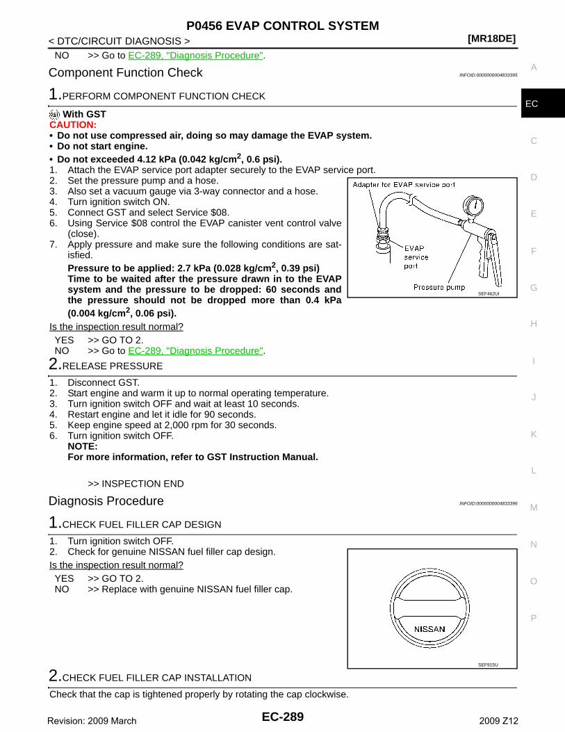
P0456 EVAP CONTROL SYSTEM[MR18DE]
C
D
E
F
G
H
I
J
K
L
M
A
C
N
P
O
< DTC/CIRCUIT DIAGNOSIS >
E
NO >> Go to EC-289, "Diagnosis Procedure".
Component Function Check INFOID:0000000004833395
1.PERFORM COMPONENT FUNCTION CHECK
With GSTCAUTION:• Do not use compressed air, doing so may damage the EVAP system.• Do not start engine.• Do not exceeded 4.12 kPa (0.042 kg/cm2, 0.6 psi).1. Attach the EVAP service port adapter securely to the EVAP service port.2. Set the pressure pump and a hose.3. Also set a vacuum gauge via 3-way connector and a hose.4. Turn ignition switch ON.5. Connect GST and select Service $08.6. Using Service $08 control the EVAP canister vent control valve
(close).7. Apply pressure and make sure the following conditions are sat-
isfied.Pressure to be applied: 2.7 kPa (0.028 kg/cm2, 0.39 psi)Time to be waited after the pressure drawn in to the EVAPsystem and the pressure to be dropped: 60 seconds andthe pressure should not be dropped more than 0.4 kPa(0.004 kg/cm2, 0.06 psi).
Is the inspection result normal?YES >> GO TO 2.NO >> Go to EC-289, "Diagnosis Procedure".
2.RELEASE PRESSURE
1. Disconnect GST.2. Start engine and warm it up to normal operating temperature.3. Turn ignition switch OFF and wait at least 10 seconds.4. Restart engine and let it idle for 90 seconds.5. Keep engine speed at 2,000 rpm for 30 seconds.6. Turn ignition switch OFF.
NOTE:For more information, refer to GST Instruction Manual.
>> INSPECTION END
Diagnosis Procedure INFOID:0000000004833396
1.CHECK FUEL FILLER CAP DESIGN
1. Turn ignition switch OFF.2. Check for genuine NISSAN fuel filler cap design.Is the inspection result normal?YES >> GO TO 2.NO >> Replace with genuine NISSAN fuel filler cap.
2.CHECK FUEL FILLER CAP INSTALLATION
Check that the cap is tightened properly by rotating the cap clockwise.
SEF462UI
SEF915U
EC-289Revision: 2009 March 2009 Z12
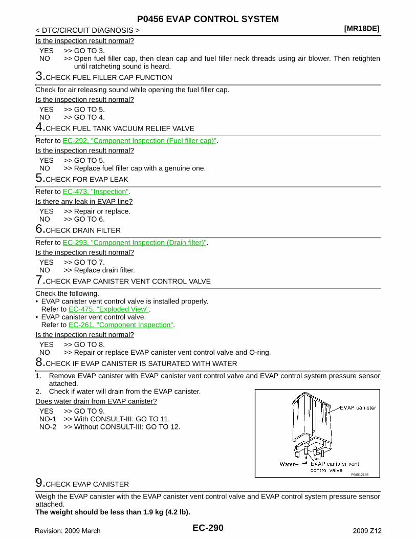
[MR18DE]P0456 EVAP CONTROL SYSTEM
< DTC/CIRCUIT DIAGNOSIS >Is the inspection result normal?YES >> GO TO 3.NO >> Open fuel filler cap, then clean cap and fuel filler neck threads using air blower. Then retighten
until ratcheting sound is heard.
3.CHECK FUEL FILLER CAP FUNCTION
Check for air releasing sound while opening the fuel filler cap.Is the inspection result normal?YES >> GO TO 5.NO >> GO TO 4.
4.CHECK FUEL TANK VACUUM RELIEF VALVE
Refer to EC-292, "Component Inspection (Fuel filler cap)".Is the inspection result normal?YES >> GO TO 5.NO >> Replace fuel filler cap with a genuine one.
5.CHECK FOR EVAP LEAK
Refer to EC-473, "Inspection".Is there any leak in EVAP line?YES >> Repair or replace.NO >> GO TO 6.
6.CHECK DRAIN FILTER
Refer to EC-293, "Component Inspection (Drain filter)".Is the inspection result normal?YES >> GO TO 7.NO >> Replace drain filter.
7.CHECK EVAP CANISTER VENT CONTROL VALVE
Check the following.• EVAP canister vent control valve is installed properly.
Refer to EC-475, "Exploded View".• EVAP canister vent control valve.
Refer to EC-261, "Component Inspection".Is the inspection result normal?YES >> GO TO 8.NO >> Repair or replace EVAP canister vent control valve and O-ring.
8.CHECK IF EVAP CANISTER IS SATURATED WITH WATER
1. Remove EVAP canister with EVAP canister vent control valve and EVAP control system pressure sensorattached.
2. Check if water will drain from the EVAP canister.Does water drain from EVAP canister?YES >> GO TO 9.NO-1 >> With CONSULT-III: GO TO 11.NO-2 >> Without CONSULT-III: GO TO 12.
9.CHECK EVAP CANISTER
Weigh the EVAP canister with the EVAP canister vent control valve and EVAP control system pressure sensorattached.The weight should be less than 1.9 kg (4.2 lb).
PBIB1213E
EC-290Revision: 2009 March 2009 Z12
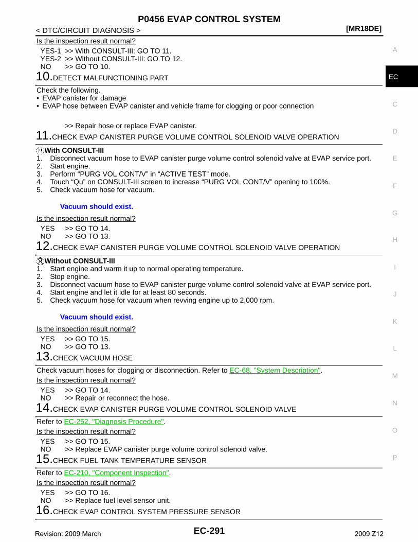
P0456 EVAP CONTROL SYSTEM[MR18DE]
C
D
E
F
G
H
I
J
K
L
M
A
C
N
P
O
< DTC/CIRCUIT DIAGNOSIS >
E
Is the inspection result normal?YES-1 >> With CONSULT-III: GO TO 11.YES-2 >> Without CONSULT-III: GO TO 12.NO >> GO TO 10.
10.DETECT MALFUNCTIONING PART
Check the following.• EVAP canister for damage• EVAP hose between EVAP canister and vehicle frame for clogging or poor connection
>> Repair hose or replace EVAP canister.
11.CHECK EVAP CANISTER PURGE VOLUME CONTROL SOLENOID VALVE OPERATION
With CONSULT-III1. Disconnect vacuum hose to EVAP canister purge volume control solenoid valve at EVAP service port.2. Start engine.3. Perform “PURG VOL CONT/V” in “ACTIVE TEST” mode.4. Touch “Qu” on CONSULT-III screen to increase “PURG VOL CONT/V” opening to 100%.5. Check vacuum hose for vacuum.
Is the inspection result normal?YES >> GO TO 14.NO >> GO TO 13.
12.CHECK EVAP CANISTER PURGE VOLUME CONTROL SOLENOID VALVE OPERATION
Without CONSULT-III1. Start engine and warm it up to normal operating temperature.2. Stop engine.3. Disconnect vacuum hose to EVAP canister purge volume control solenoid valve at EVAP service port.4. Start engine and let it idle for at least 80 seconds.5. Check vacuum hose for vacuum when revving engine up to 2,000 rpm.
Is the inspection result normal?YES >> GO TO 15.NO >> GO TO 13.
13.CHECK VACUUM HOSE
Check vacuum hoses for clogging or disconnection. Refer to EC-68, "System Description".Is the inspection result normal?YES >> GO TO 14.NO >> Repair or reconnect the hose.
14.CHECK EVAP CANISTER PURGE VOLUME CONTROL SOLENOID VALVE
Refer to EC-252, "Diagnosis Procedure".Is the inspection result normal?YES >> GO TO 15.NO >> Replace EVAP canister purge volume control solenoid valve.
15.CHECK FUEL TANK TEMPERATURE SENSOR
Refer to EC-210, "Component Inspection".Is the inspection result normal?YES >> GO TO 16.NO >> Replace fuel level sensor unit.
16.CHECK EVAP CONTROL SYSTEM PRESSURE SENSOR
Vacuum should exist.
Vacuum should exist.
EC-291Revision: 2009 March 2009 Z12
[MR18DE]P0456 EVAP CONTROL SYSTEM
< DTC/CIRCUIT DIAGNOSIS >Refer to EC-269, "Component Inspection".Is the inspection result normal?YES >> GO TO 17.NO >> Replace EVAP control system pressure sensor.
17.CHECK EVAP PURGE LINE
Check EVAP purge line (pipe, rubber tube, fuel tank and EVAP canister) for cracks or improper connection.Refer to EC-68, "System Description".Is the inspection result normal?YES >> GO TO 18.NO >> Repair or reconnect the hose.
18.CLEAN EVAP PURGE LINE
Clean EVAP purge line (pipe and rubber tube) using air blower.
>> GO TO 19.
19.CHECK EVAP/ORVR LINE
Check EVAP/ORVR line between EVAP canister and fuel tank for clogging, kink, looseness and improper con-nection. For location, refer to EC-407, "Description".Is the inspection result normal?YES >> GO TO 20.NO >> Repair or replace hoses and tubes.
20.CHECK RECIRCULATION LINE
Check recirculation line between fuel filler tube and fuel tank for clogging, kink, cracks, looseness andimproper connection.Is the inspection result normal?YES >> GO TO 21.NO >> Repair or replace hose, tube or fuel filler tube.
21.CHECK REFUELING EVAP VAPOR CUT VALVE
Refer to EC-410, "Component Inspection (Refueling EVAP vapor cut valve)".Is the inspection result normal?YES >> GO TO 22.NO >> Replace refueling EVAP vapor cut valve with fuel tank.
22.CHECK FUEL LEVEL SENSOR
Refer to FL-8, "Inspection".Is the inspection result normal?YES >> GO TO 23.NO >> Replace fuel level sensor unit.
23.CHECK INTERMITTENT INCIDENT
Refer to GI-34, "Intermittent Incident".
>> INSPECTION END
Component Inspection (Fuel filler cap) INFOID:0000000004833397
1.CHECK FUEL FILLER CAP
1. Turn ignition switch OFF.2. Remove fuel filler cap.
EC-292Revision: 2009 March 2009 Z12
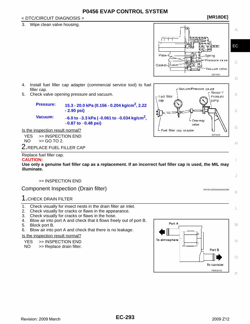
P0456 EVAP CONTROL SYSTEM[MR18DE]
C
D
E
F
G
H
I
J
K
L
M
A
C
N
P
O
< DTC/CIRCUIT DIAGNOSIS >
E
3. Wipe clean valve housing.
4. Install fuel filler cap adapter (commercial service tool) to fuelfiller cap.
5. Check valve opening pressure and vacuum.
Is the inspection result normal?YES >> INSPECTION ENDNO >> GO TO 2.
2.REPLACE FUEL FILLER CAP
Replace fuel filler cap.CAUTION:Use only a genuine fuel filler cap as a replacement. If an incorrect fuel filler cap is used, the MIL mayilluminate.
>> INSPECTION END
Component Inspection (Drain filter) INFOID:0000000004833398
1.CHECK DRAIN FILTER
1. Check visually for insect nests in the drain filter air inlet.2. Check visually for cracks or flaws in the appearance.3. Check visually for cracks or flaws in the hose.4. Blow air into port A and check that it flows freely out of port B.5. Block port B.6. Blow air into port A and check that there is no leakage.Is the inspection result normal?YES >> INSPECTION ENDNO >> Replace drain filter.
SEF445Y
Pressure: 15.3 - 20.0 kPa (0.156 - 0.204 kg/cm2, 2.22 - 2.90 psi)
Vacuum: −6.0 to −3.3 kPa (−0.061 to −0.034 kg/cm2, −0.87 to −0.48 psi)
SEF943S
PBIB3641E
EC-293Revision: 2009 March 2009 Z12
[MR18DE]P0460 FUEL LEVEL SENSOR
< DTC/CIRCUIT DIAGNOSIS >
P0460 FUEL LEVEL SENSOR
Description INFOID:0000000004833399
The fuel level sensor is mounted in the fuel level sensor unit.The sensor detects a fuel level in the fuel tank and transmits a signal to the combination meter. The combina-tion meter sends the fuel level sensor signal to the ECM via the CAN communication line.It consists of two parts, one is mechanical float and the other is variable resistor. Fuel level sensor output volt-age changes depending on the movement of the fuel mechanical float.
DTC Logic INFOID:0000000004833400
DTC DETECTION LOGICNOTE:• If DTC P0460 is displayed with DTC UXXXX, first perform the trouble diagnosis for DTC UXXXX.• If DTC P0460 is displayed with DTC P0607, first perform the trouble diagnosis for DTC P0607. Refer
to EC-307, "DTC Logic".When the vehicle is parked, naturally the fuel level in the fuel tank is stable. It means that output signal of thefuel level sensor does not change. If ECM senses sloshing signal from the sensor, fuel level sensor malfunc-tion is detected.
DTC CONFIRMATION PROCEDURE
1.PRECONDITIONING
If DTC Confirmation Procedure has been previously conducted, always turn ignition switch OFF and wait atleast 10 seconds before conducting the next test.
>> GO TO 2.
2.PERFORM DTC CONFIRMATION PROCEDURE
1. Start engine and wait maximum of 2 consecutive minutes.2. Check 1st trip DTC.Is 1st trip DTC detected?YES >> Go to EC-294, "Diagnosis Procedure".NO >> INSPECTION END
Diagnosis Procedure INFOID:0000000004833401
1.CHECK COMBINATION METER FUNCTION
Refer to MWI-30, "CONSULT-III Function (METER/M&A)".Is the inspection result normal?YES >> GO TO 2.NO >> Refer to MWI-42, "Component Function Check"
2.CHECK INTERMITTENT INCIDENT
Refer to GI-34, "Intermittent Incident".
>> INSPECTION END
DTC No. Trouble diagnosis name DTC detecting condition Possible cause
P0460Fuel level sensor circuit noise
Even though the vehicle is parked, a signal be-ing varied is sent from the fuel level sensor to ECM.
• Harness or connectors(The CAN communication line is open or shorted)
• Harness or connectors(The sensor circuit is open or shorted)
• Combination meter• Fuel level sensor
EC-294Revision: 2009 March 2009 Z12
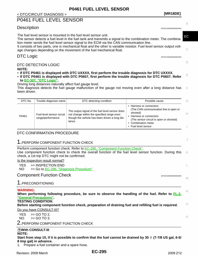
P0461 FUEL LEVEL SENSOR[MR18DE]
C
D
E
F
G
H
I
J
K
L
M
A
C
N
P
O
< DTC/CIRCUIT DIAGNOSIS >
E
P0461 FUEL LEVEL SENSOR
Description INFOID:0000000004833402
The fuel level sensor is mounted in the fuel level sensor unit.The sensor detects a fuel level in the fuel tank and transmits a signal to the combination meter. The combina-tion meter sends the fuel level sensor signal to the ECM via the CAN communication line.It consists of two parts, one is mechanical float and the other is variable resistor. Fuel level sensor output volt-age changes depending on the movement of the fuel mechanical float.
DTC Logic INFOID:0000000004833403
DTC DETECTION LOGICNOTE:• If DTC P0461 is displayed with DTC UXXXX, first perform the trouble diagnosis for DTC UXXXX.• If DTC P0461 is displayed with DTC P0607, first perform the trouble diagnosis for DTC P0607. Refer
to EC-307, "DTC Logic".Driving long distances naturally affect fuel gauge level.This diagnosis detects the fuel gauge malfunction of the gauge not moving even after a long distance hasbeen driven.
DTC CONFIRMATION PROCEDURE
1.PERFORM COMPONENT FUNCTION CHECK
Perform component function check. Refer to EC-295, "Component Function Check".Use component function check to check the overall function of the fuel level sensor function. During thischeck, a 1st trip DTC might not be confirmed.Is the inspection result normal?YES >> INSPECTION ENDNO >> Go to EC-296, "Diagnosis Procedure".
Component Function Check INFOID:0000000004833404
1.PRECONDITIONING
WARNING:When performing following procedure, be sure to observe the handling of the fuel. Refer to FL-2,"General Precautions".TESTING CONDITION:Before starting component function check, preparation of draining fuel and refilling fuel is required.Do you have CONSULT-III?YES >> GO TO 2.NO >> GO TO 3.
2.PERFORM COMPONENT FUNCTION CHECK
With CONSULT-IIINOTE:Start from step 10, if it is possible to confirm that the fuel cannot be drained by 30 (7-7/8 US gal, 6-5/8 Imp gal) in advance.1. Prepare a fuel container and a spare hose.
DTC No. Trouble diagnosis name DTC detecting condition Possible cause
P0461Fuel level sensor circuit range/performance
The output signal of the fuel level sensor does not change within the specified range even though the vehicle has been driven a long dis-tance.
• Harness or connectors(The CAN communication line is open or shorted)
• Harness or connectors(The sensor circuit is open or shorted)
• Combination meter• Fuel level sensor
EC-295Revision: 2009 March 2009 Z12
[MR18DE]P0461 FUEL LEVEL SENSOR
< DTC/CIRCUIT DIAGNOSIS >2. Release fuel pressure from fuel line, refer to EC-471, "Inspection".3. Remove the fuel feed hose on the fuel level sensor unit.4. Connect a spare fuel hose where the fuel feed hose was removed.5. Turn ignition switch OFF and wait at least 10 seconds then turn ON.6. Select “FUEL LEVEL SE” in “DATA MONITOR” mode with CONSULT-III.7. Check “FUEL LEVEL SE” output voltage and note it.8. Select “FUEL PUMP RELAY” in “ACTIVE TEST” mode with CONSULT-III.9. Touch “ON” and drain fuel approximately 30 (7-7/8 US gal, 6-5/8 Imp gal) and stop it.10. Check “FUEL LEVEL SE” output voltage and note it.11. Fill fuel into the fuel tank for 30 (7-7/8 US gal, 6-5/8 Imp gal).12. Check “FUEL LEVEL SE” output voltage and note it.13. Confirm whether the voltage changes more than 0.03 V during step 7 to 10 and 10 to 12.Is the inspection result normal?YES >> INSPECTION ENDNO >> Go to EC-296, "Diagnosis Procedure".
3.PERFORM COMPONENT FUNCTION CHECK
Without CONSULT-IIINOTE:Start from step 8, if it is possible to confirm that the fuel cannot be drained by 30 (7-7/8 US gal, 6-5/8Imp gal) in advance.1. Prepare a fuel container and a spare hose.2. Release fuel pressure from fuel line. Refer to EC-471, "Inspection".3. Remove the fuel feed hose on the fuel level sensor unit.4. Connect a spare fuel hose where the fuel feed hose was removed.5. Turn ignition switch ON.6. Drain fuel by 30 (7-7/8 US gal, 6-5/8 Imp gal) from the fuel tank using proper equipment.7. Confirm that the fuel gauge indication varies.8. Fill fuel into the fuel tank for 30 (7-7/8 US gal, 6-5/8 Imp gal).9. Confirm that the fuel gauge indication varies.Is the inspection result normal?YES >> INSPECTION ENDNO >> Go to EC-296, "Diagnosis Procedure".
Diagnosis Procedure INFOID:0000000004833405
1.CHECK COMBINATION METER FUNCTION
Refer to MWI-30, "CONSULT-III Function (METER/M&A)".Is the inspection result normal?YES >> GO TO 2.NO >> Refer to MWI-42, "Component Function Check"
2.CHECK INTERMITTENT INCIDENT
Refer to GI-34, "Intermittent Incident".
>> INSPECTION END
EC-296Revision: 2009 March 2009 Z12
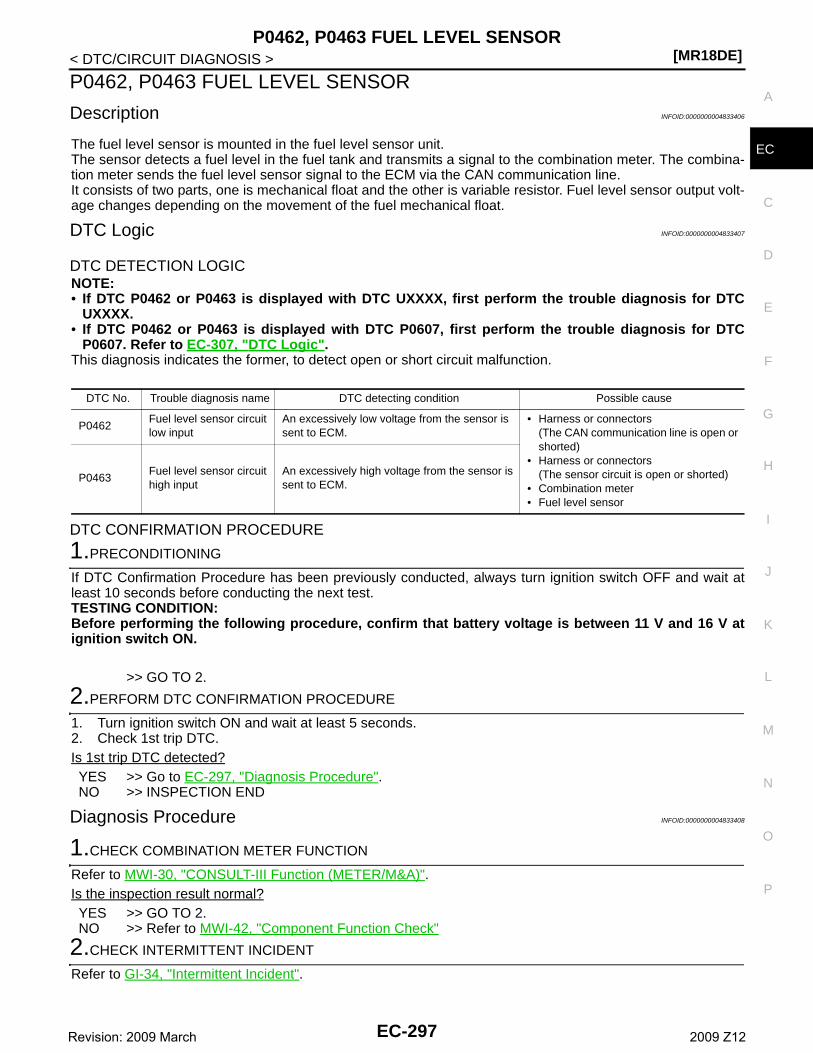
P0462, P0463 FUEL LEVEL SENSOR[MR18DE]
C
D
E
F
G
H
I
J
K
L
M
A
C
N
P
O
< DTC/CIRCUIT DIAGNOSIS >
E
P0462, P0463 FUEL LEVEL SENSOR
Description INFOID:0000000004833406
The fuel level sensor is mounted in the fuel level sensor unit.The sensor detects a fuel level in the fuel tank and transmits a signal to the combination meter. The combina-tion meter sends the fuel level sensor signal to the ECM via the CAN communication line.It consists of two parts, one is mechanical float and the other is variable resistor. Fuel level sensor output volt-age changes depending on the movement of the fuel mechanical float.
DTC Logic INFOID:0000000004833407
DTC DETECTION LOGICNOTE:• If DTC P0462 or P0463 is displayed with DTC UXXXX, first perform the trouble diagnosis for DTC
UXXXX.• If DTC P0462 or P0463 is displayed with DTC P0607, first perform the trouble diagnosis for DTC
P0607. Refer to EC-307, "DTC Logic".This diagnosis indicates the former, to detect open or short circuit malfunction.
DTC CONFIRMATION PROCEDURE
1.PRECONDITIONING
If DTC Confirmation Procedure has been previously conducted, always turn ignition switch OFF and wait atleast 10 seconds before conducting the next test.TESTING CONDITION:Before performing the following procedure, confirm that battery voltage is between 11 V and 16 V atignition switch ON.
>> GO TO 2.
2.PERFORM DTC CONFIRMATION PROCEDURE
1. Turn ignition switch ON and wait at least 5 seconds.2. Check 1st trip DTC.Is 1st trip DTC detected?YES >> Go to EC-297, "Diagnosis Procedure".NO >> INSPECTION END
Diagnosis Procedure INFOID:0000000004833408
1.CHECK COMBINATION METER FUNCTION
Refer to MWI-30, "CONSULT-III Function (METER/M&A)".Is the inspection result normal?YES >> GO TO 2.NO >> Refer to MWI-42, "Component Function Check"
2.CHECK INTERMITTENT INCIDENT
Refer to GI-34, "Intermittent Incident".
DTC No. Trouble diagnosis name DTC detecting condition Possible cause
P0462Fuel level sensor circuit low input
An excessively low voltage from the sensor is sent to ECM.
• Harness or connectors(The CAN communication line is open or shorted)
• Harness or connectors(The sensor circuit is open or shorted)
• Combination meter• Fuel level sensor
P0463Fuel level sensor circuit high input
An excessively high voltage from the sensor is sent to ECM.
EC-297Revision: 2009 March 2009 Z12
[MR18DE]P0462, P0463 FUEL LEVEL SENSOR
< DTC/CIRCUIT DIAGNOSIS >>> INSPECTION END
EC-298Revision: 2009 March 2009 Z12
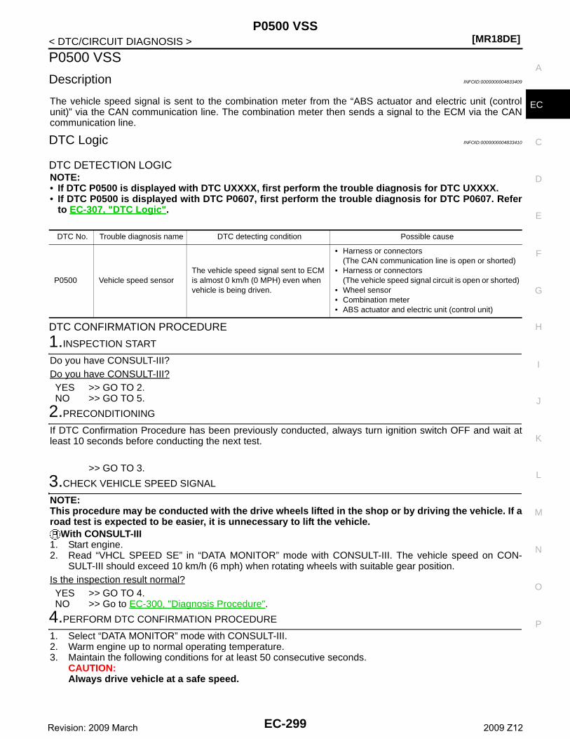
P0500 VSS[MR18DE]
C
D
E
F
G
H
I
J
K
L
M
A
C
N
P
O
< DTC/CIRCUIT DIAGNOSIS >
E
P0500 VSS
Description INFOID:0000000004833409
The vehicle speed signal is sent to the combination meter from the “ABS actuator and electric unit (controlunit)” via the CAN communication line. The combination meter then sends a signal to the ECM via the CANcommunication line.
DTC Logic INFOID:0000000004833410
DTC DETECTION LOGICNOTE:• If DTC P0500 is displayed with DTC UXXXX, first perform the trouble diagnosis for DTC UXXXX.• If DTC P0500 is displayed with DTC P0607, first perform the trouble diagnosis for DTC P0607. Refer
to EC-307, "DTC Logic".
DTC CONFIRMATION PROCEDURE
1.INSPECTION START
Do you have CONSULT-III?Do you have CONSULT-III?YES >> GO TO 2.NO >> GO TO 5.
2.PRECONDITIONING
If DTC Confirmation Procedure has been previously conducted, always turn ignition switch OFF and wait atleast 10 seconds before conducting the next test.
>> GO TO 3.
3.CHECK VEHICLE SPEED SIGNAL
NOTE:This procedure may be conducted with the drive wheels lifted in the shop or by driving the vehicle. If aroad test is expected to be easier, it is unnecessary to lift the vehicle.
With CONSULT-III1. Start engine.2. Read “VHCL SPEED SE” in “DATA MONITOR” mode with CONSULT-III. The vehicle speed on CON-
SULT-III should exceed 10 km/h (6 mph) when rotating wheels with suitable gear position.Is the inspection result normal?YES >> GO TO 4.NO >> Go to EC-300, "Diagnosis Procedure".
4.PERFORM DTC CONFIRMATION PROCEDURE
1. Select “DATA MONITOR” mode with CONSULT-III.2. Warm engine up to normal operating temperature.3. Maintain the following conditions for at least 50 consecutive seconds.
CAUTION:Always drive vehicle at a safe speed.
DTC No. Trouble diagnosis name DTC detecting condition Possible cause
P0500 Vehicle speed sensorThe vehicle speed signal sent to ECM is almost 0 km/h (0 MPH) even when vehicle is being driven.
• Harness or connectors(The CAN communication line is open or shorted)
• Harness or connectors(The vehicle speed signal circuit is open or shorted)
• Wheel sensor• Combination meter• ABS actuator and electric unit (control unit)
EC-299Revision: 2009 March 2009 Z12
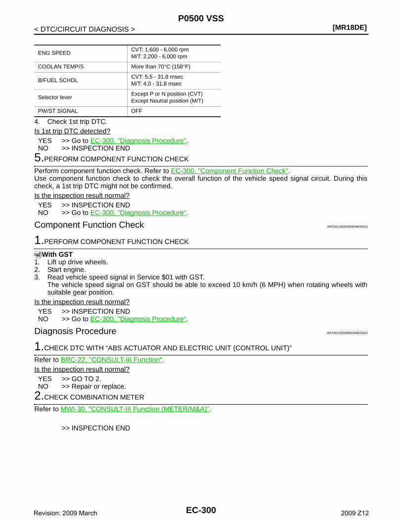
[MR18DE]P0500 VSS
< DTC/CIRCUIT DIAGNOSIS >
4. Check 1st trip DTC.Is 1st trip DTC detected?YES >> Go to EC-300, "Diagnosis Procedure".NO >> INSPECTION END
5.PERFORM COMPONENT FUNCTION CHECK
Perform component function check. Refer to EC-300, "Component Function Check".Use component function check to check the overall function of the vehicle speed signal circuit. During thischeck, a 1st trip DTC might not be confirmed.Is the inspection result normal?YES >> INSPECTION ENDNO >> Go to EC-300, "Diagnosis Procedure".
Component Function Check INFOID:0000000004833411
1.PERFORM COMPONENT FUNCTION CHECK
With GST1. Lift up drive wheels.2. Start engine.3. Read vehicle speed signal in Service $01 with GST.
The vehicle speed signal on GST should be able to exceed 10 km/h (6 MPH) when rotating wheels withsuitable gear position.
Is the inspection result normal?YES >> INSPECTION ENDNO >> Go to EC-300, "Diagnosis Procedure".
Diagnosis Procedure INFOID:0000000004833412
1.CHECK DTC WITH “ABS ACTUATOR AND ELECTRIC UNIT (CONTROL UNIT)”
Refer to BRC-22, "CONSULT-III Function".Is the inspection result normal?YES >> GO TO 2.NO >> Repair or replace.
2.CHECK COMBINATION METER
Refer to MWI-30, "CONSULT-III Function (METER/M&A)".
>> INSPECTION END
ENG SPEEDCVT: 1,600 - 6,000 rpmM/T: 2,200 - 6,000 rpm
COOLAN TEMP/S More than 70°C (158°F)
B/FUEL SCHDLCVT: 5.5 - 31.8 msecM/T: 4.0 - 31.8 msec
Selector leverExcept P or N position (CVT)Except Neutral position (M/T)
PW/ST SIGNAL OFF
EC-300Revision: 2009 March 2009 Z12
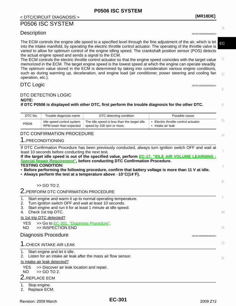
P0506 ISC SYSTEM[MR18DE]
C
D
E
F
G
H
I
J
K
L
M
A
C
N
P
O
< DTC/CIRCUIT DIAGNOSIS >
E
P0506 ISC SYSTEM
Description INFOID:0000000004833413
The ECM controls the engine idle speed to a specified level through the fine adjustment of the air, which is letinto the intake manifold, by operating the electric throttle control actuator. The operating of the throttle valve isvaried to allow for optimum control of the engine idling speed. The crankshaft position sensor (POS) detectsthe actual engine speed and sends a signal to the ECM.The ECM controls the electric throttle control actuator so that the engine speed coincides with the target valuememorized in the ECM. The target engine speed is the lowest speed at which the engine can operate steadily.The optimum value stored in the ECM is determined by taking into consideration various engine conditions,such as during warming up, deceleration, and engine load (air conditioner, power steering and cooling fanoperation, etc.).
DTC Logic INFOID:0000000004833414
DTC DETECTION LOGICNOTE:If DTC P0506 is displayed with other DTC, first perform the trouble diagnosis for the other DTC.
DTC CONFIRMATION PROCEDURE
1.PRECONDITIONING
If DTC Confirmation Procedure has been previously conducted, always turn ignition switch OFF and wait atleast 10 seconds before conducting the next test.If the target idle speed is out of the specified value, perform EC-17, "IDLE AIR VOLUME LEARNING :Special Repair Requirement", before conducting DTC Confirmation Procedure.TESTING CONDITION:• Before performing the following procedure, confirm that battery voltage is more than 11 V at idle.• Always perform the test at a temperature above −10°C(14°F).
>> GO TO 2.
2.PERFORM DTC CONFIRMATION PROCEDURE
1. Start engine and warm it up to normal operating temperature.2. Turn ignition switch OFF and wait at least 10 seconds.3. Start engine and run it for at least 1 minute at idle speed.4. Check 1st trip DTC.Is 1st trip DTC detected?YES >> Go to EC-301, "Diagnosis Procedure".NO >> INSPECTION END
Diagnosis Procedure INFOID:0000000004833415
1.CHECK INTAKE AIR LEAK
1. Start engine and let it idle.2. Listen for an intake air leak after the mass air flow sensor.Is intake air leak detected?YES >> Discover air leak location and repair.NO >> GO TO 2.
2.REPLACE ECM
1. Stop engine.2. Replace ECM.
DTC No. Trouble diagnosis name DTC detecting condition Possible cause
P0506Idle speed control system RPM lower than expected
The idle speed is less than the target idle speed by 100 rpm or more.
• Electric throttle control actuator• Intake air leak
EC-301Revision: 2009 March 2009 Z12
[MR18DE]P0506 ISC SYSTEM
< DTC/CIRCUIT DIAGNOSIS >3. Perform EC-15, "ADDITIONAL SERVICE WHEN REPLACING CONTROL UNIT : Special Repair Require-
ment".
>> INSPECTION END
EC-302Revision: 2009 March 2009 Z12
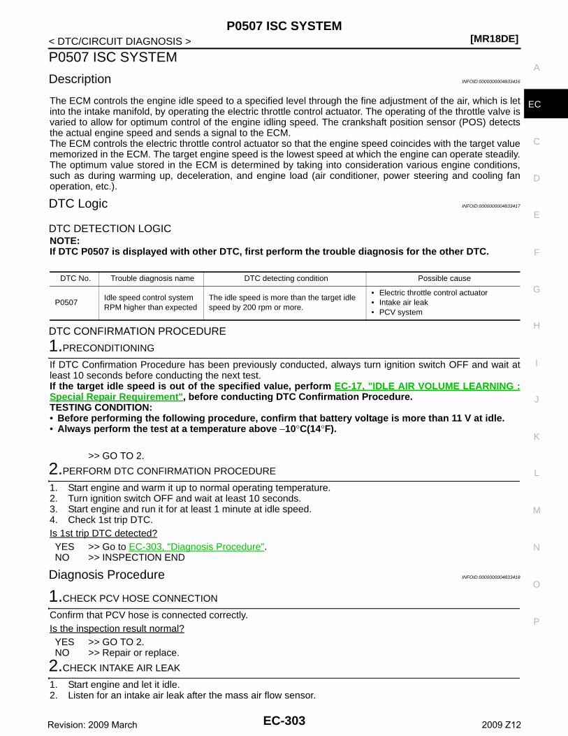
P0507 ISC SYSTEM[MR18DE]
C
D
E
F
G
H
I
J
K
L
M
A
C
N
P
O
< DTC/CIRCUIT DIAGNOSIS >
E
P0507 ISC SYSTEM
Description INFOID:0000000004833416
The ECM controls the engine idle speed to a specified level through the fine adjustment of the air, which is letinto the intake manifold, by operating the electric throttle control actuator. The operating of the throttle valve isvaried to allow for optimum control of the engine idling speed. The crankshaft position sensor (POS) detectsthe actual engine speed and sends a signal to the ECM.The ECM controls the electric throttle control actuator so that the engine speed coincides with the target valuememorized in the ECM. The target engine speed is the lowest speed at which the engine can operate steadily.The optimum value stored in the ECM is determined by taking into consideration various engine conditions,such as during warming up, deceleration, and engine load (air conditioner, power steering and cooling fanoperation, etc.).
DTC Logic INFOID:0000000004833417
DTC DETECTION LOGICNOTE:If DTC P0507 is displayed with other DTC, first perform the trouble diagnosis for the other DTC.
DTC CONFIRMATION PROCEDURE
1.PRECONDITIONING
If DTC Confirmation Procedure has been previously conducted, always turn ignition switch OFF and wait atleast 10 seconds before conducting the next test.If the target idle speed is out of the specified value, perform EC-17, "IDLE AIR VOLUME LEARNING :Special Repair Requirement", before conducting DTC Confirmation Procedure.TESTING CONDITION:• Before performing the following procedure, confirm that battery voltage is more than 11 V at idle.• Always perform the test at a temperature above −10°C(14°F).
>> GO TO 2.
2.PERFORM DTC CONFIRMATION PROCEDURE
1. Start engine and warm it up to normal operating temperature.2. Turn ignition switch OFF and wait at least 10 seconds.3. Start engine and run it for at least 1 minute at idle speed.4. Check 1st trip DTC.Is 1st trip DTC detected?YES >> Go to EC-303, "Diagnosis Procedure".NO >> INSPECTION END
Diagnosis Procedure INFOID:0000000004833418
1.CHECK PCV HOSE CONNECTION
Confirm that PCV hose is connected correctly.Is the inspection result normal?YES >> GO TO 2.NO >> Repair or replace.
2.CHECK INTAKE AIR LEAK
1. Start engine and let it idle.2. Listen for an intake air leak after the mass air flow sensor.
DTC No. Trouble diagnosis name DTC detecting condition Possible cause
P0507Idle speed control system RPM higher than expected
The idle speed is more than the target idle speed by 200 rpm or more.
• Electric throttle control actuator• Intake air leak• PCV system
EC-303Revision: 2009 March 2009 Z12
[MR18DE]P0507 ISC SYSTEM
< DTC/CIRCUIT DIAGNOSIS >Is intake air leak detected?YES >> Discover air leak location and repair.NO >> GO TO 3.
3.REPLACE ECM
1. Stop engine.2. Replace ECM.3. Perform EC-15, "ADDITIONAL SERVICE WHEN REPLACING CONTROL UNIT : Special Repair Require-
ment".
>> INSPECTION END
EC-304Revision: 2009 March 2009 Z12
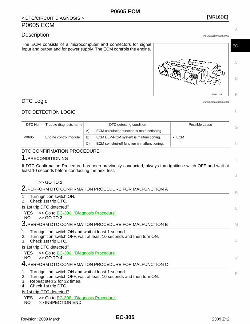
P0605 ECM[MR18DE]
C
D
E
F
G
H
I
J
K
L
M
A
C
N
P
O
< DTC/CIRCUIT DIAGNOSIS >
E
P0605 ECM
Description INFOID:0000000004833422
The ECM consists of a microcomputer and connectors for signalinput and output and for power supply. The ECM controls the engine.
DTC Logic INFOID:0000000004833423
DTC DETECTION LOGIC
DTC CONFIRMATION PROCEDURE
1.PRECONDITIONING
If DTC Confirmation Procedure has been previously conducted, always turn ignition switch OFF and wait atleast 10 seconds before conducting the next test.
>> GO TO 2.
2.PERFORM DTC CONFIRMATION PROCEDURE FOR MALFUNCTION A
1. Turn ignition switch ON.2. Check 1st trip DTC.Is 1st trip DTC detected?YES >> Go to EC-306, "Diagnosis Procedure".NO >> GO TO 3.
3.PERFORM DTC CONFIRMATION PROCEDURE FOR MALFUNCTION B
1. Turn ignition switch ON and wait at least 1 second.2. Turn ignition switch OFF, wait at least 10 seconds and then turn ON.3. Check 1st trip DTC.Is 1st trip DTC detected?YES >> Go to EC-306, "Diagnosis Procedure".NO >> GO TO 4.
4.PERFORM DTC CONFIRMATION PROCEDURE FOR MALFUNCTION C
1. Turn ignition switch ON and wait at least 1 second.2. Turn ignition switch OFF, wait at least 10 seconds and then turn ON.3. Repeat step 2 for 32 times.4. Check 1st trip DTC.Is 1st trip DTC detected?YES >> Go to EC-306, "Diagnosis Procedure".NO >> INSPECTION END
PBIA9222J
DTC No. Trouble diagnosis name DTC detecting condition Possible cause
P0605 Engine control module
A) ECM calculation function is malfunctioning.
• ECMB) ECM EEP-ROM system is malfunctioning.
C) ECM self shut-off function is malfunctioning.
EC-305Revision: 2009 March 2009 Z12
[MR18DE]P0605 ECM
< DTC/CIRCUIT DIAGNOSIS >
Diagnosis Procedure INFOID:0000000004833424
1.INSPECTION START
1. Turn ignition switch ON.2. Erase 1st trip DTC. Refer to “How to Erase DTC and 1st Trip DTC” in EC-85, "Diagnosis Description".3. Perform DTC CONFIRMATION PROCEDURE. Refer to EC-305, "DTC Logic".Is the 1st trip DTC P0605 displayed again?YES >> GO TO 2.NO >> INSPECTION END
2.REPLACE ECM
1. Replace ECM.2. Perform EC-15, "ADDITIONAL SERVICE WHEN REPLACING CONTROL UNIT : Special Repair Require-
ment".
>> INSPECTION END
EC-306Revision: 2009 March 2009 Z12
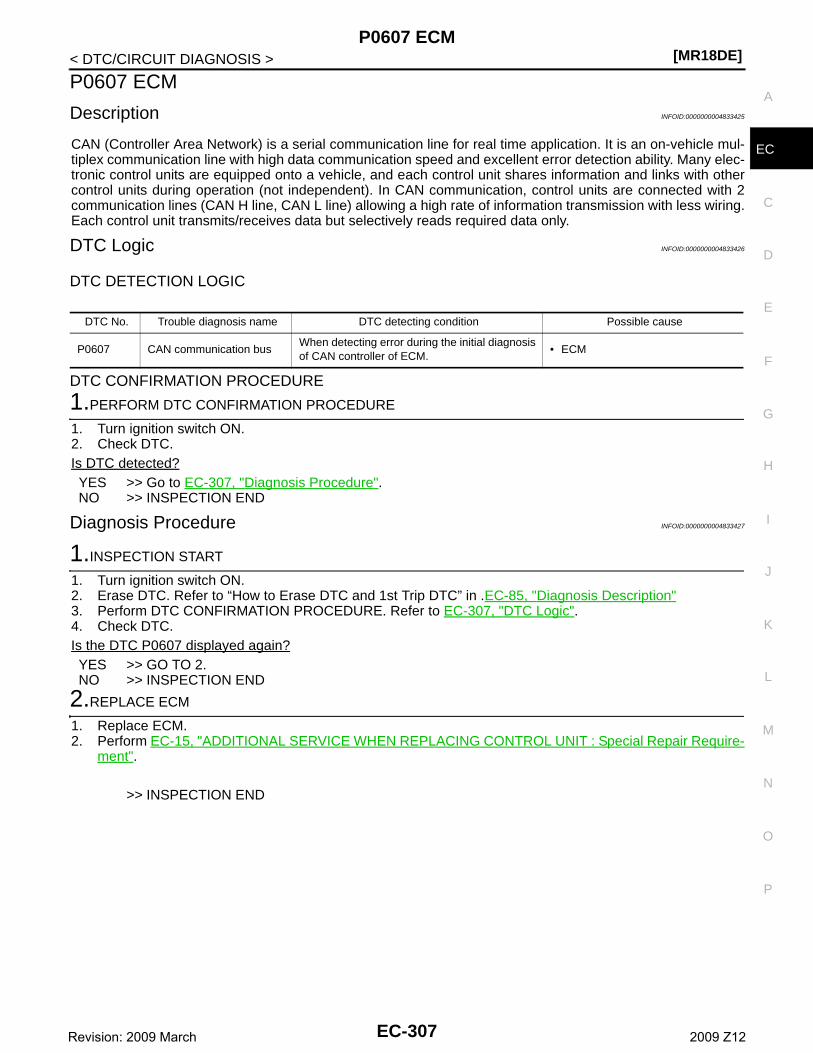
P0607 ECM[MR18DE]
C
D
E
F
G
H
I
J
K
L
M
A
C
N
P
O
< DTC/CIRCUIT DIAGNOSIS >
E
P0607 ECM
Description INFOID:0000000004833425
CAN (Controller Area Network) is a serial communication line for real time application. It is an on-vehicle mul-tiplex communication line with high data communication speed and excellent error detection ability. Many elec-tronic control units are equipped onto a vehicle, and each control unit shares information and links with othercontrol units during operation (not independent). In CAN communication, control units are connected with 2communication lines (CAN H line, CAN L line) allowing a high rate of information transmission with less wiring.Each control unit transmits/receives data but selectively reads required data only.
DTC Logic INFOID:0000000004833426
DTC DETECTION LOGIC
DTC CONFIRMATION PROCEDURE
1.PERFORM DTC CONFIRMATION PROCEDURE
1. Turn ignition switch ON.2. Check DTC.Is DTC detected?YES >> Go to EC-307, "Diagnosis Procedure".NO >> INSPECTION END
Diagnosis Procedure INFOID:0000000004833427
1.INSPECTION START
1. Turn ignition switch ON.2. Erase DTC. Refer to “How to Erase DTC and 1st Trip DTC” in .EC-85, "Diagnosis Description"3. Perform DTC CONFIRMATION PROCEDURE. Refer to EC-307, "DTC Logic".4. Check DTC.Is the DTC P0607 displayed again?YES >> GO TO 2.NO >> INSPECTION END
2.REPLACE ECM
1. Replace ECM.2. Perform EC-15, "ADDITIONAL SERVICE WHEN REPLACING CONTROL UNIT : Special Repair Require-
ment".
>> INSPECTION END
DTC No. Trouble diagnosis name DTC detecting condition Possible cause
P0607 CAN communication busWhen detecting error during the initial diagnosis of CAN controller of ECM.
• ECM
EC-307Revision: 2009 March 2009 Z12
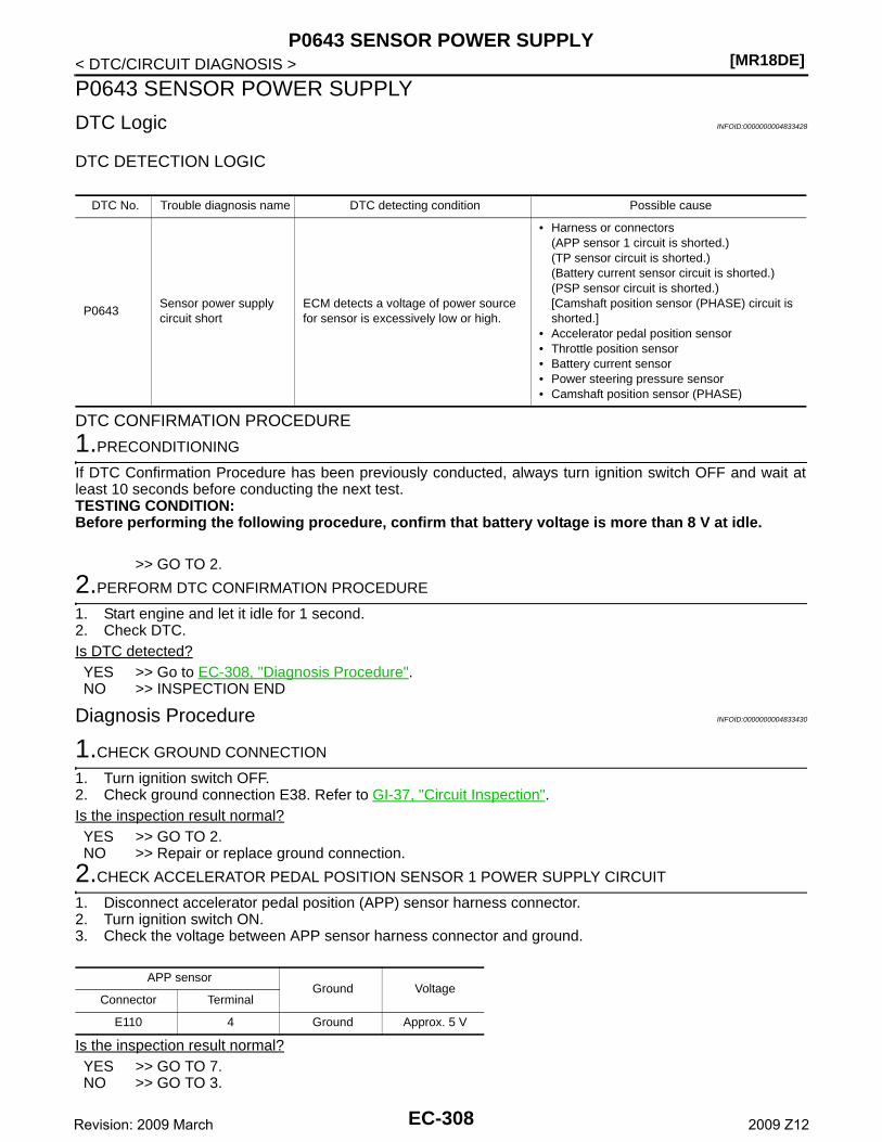
[MR18DE]P0643 SENSOR POWER SUPPLY
< DTC/CIRCUIT DIAGNOSIS >
P0643 SENSOR POWER SUPPLY
DTC Logic INFOID:0000000004833428
DTC DETECTION LOGIC
DTC CONFIRMATION PROCEDURE
1.PRECONDITIONING
If DTC Confirmation Procedure has been previously conducted, always turn ignition switch OFF and wait atleast 10 seconds before conducting the next test.TESTING CONDITION:Before performing the following procedure, confirm that battery voltage is more than 8 V at idle.
>> GO TO 2.
2.PERFORM DTC CONFIRMATION PROCEDURE
1. Start engine and let it idle for 1 second.2. Check DTC.Is DTC detected?YES >> Go to EC-308, "Diagnosis Procedure".NO >> INSPECTION END
Diagnosis Procedure INFOID:0000000004833430
1.CHECK GROUND CONNECTION
1. Turn ignition switch OFF.2. Check ground connection E38. Refer to GI-37, "Circuit Inspection". Is the inspection result normal?YES >> GO TO 2.NO >> Repair or replace ground connection.
2.CHECK ACCELERATOR PEDAL POSITION SENSOR 1 POWER SUPPLY CIRCUIT
1. Disconnect accelerator pedal position (APP) sensor harness connector.2. Turn ignition switch ON.3. Check the voltage between APP sensor harness connector and ground.
Is the inspection result normal?YES >> GO TO 7.NO >> GO TO 3.
DTC No. Trouble diagnosis name DTC detecting condition Possible cause
P0643Sensor power supply circuit short
ECM detects a voltage of power source for sensor is excessively low or high.
• Harness or connectors(APP sensor 1 circuit is shorted.)(TP sensor circuit is shorted.)(Battery current sensor circuit is shorted.)(PSP sensor circuit is shorted.)[Camshaft position sensor (PHASE) circuit is shorted.]
• Accelerator pedal position sensor• Throttle position sensor• Battery current sensor• Power steering pressure sensor• Camshaft position sensor (PHASE)
APP sensorGround Voltage
Connector Terminal
E110 4 Ground Approx. 5 V
EC-308Revision: 2009 March 2009 Z12
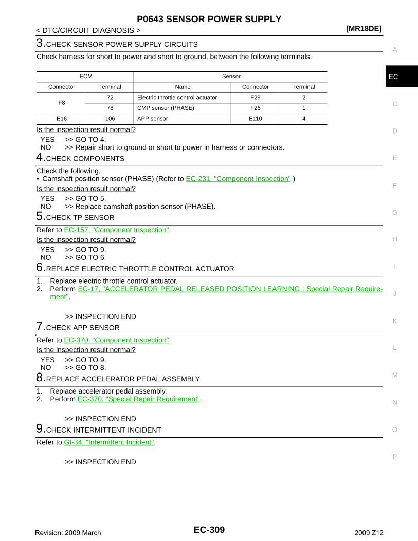
P0643 SENSOR POWER SUPPLY[MR18DE]
C
D
E
F
G
H
I
J
K
L
M
A
C
N
P
O
< DTC/CIRCUIT DIAGNOSIS >
E
3.CHECK SENSOR POWER SUPPLY CIRCUITS
Check harness for short to power and short to ground, between the following terminals.
Is the inspection result normal?YES >> GO TO 4.NO >> Repair short to ground or short to power in harness or connectors.
4.CHECK COMPONENTS
Check the following.• Camshaft position sensor (PHASE) (Refer to EC-231, "Component Inspection".)Is the inspection result normal?YES >> GO TO 5.NO >> Replace camshaft position sensor (PHASE).
5.CHECK TP SENSOR
Refer to EC-157, "Component Inspection".Is the inspection result normal?YES >> GO TO 9.NO >> GO TO 6.
6.REPLACE ELECTRIC THROTTLE CONTROL ACTUATOR
1. Replace electric throttle control actuator.2. Perform EC-17, "ACCELERATOR PEDAL RELEASED POSITION LEARNING : Special Repair Require-
ment".
>> INSPECTION END
7.CHECK APP SENSOR
Refer to EC-370, "Component Inspection".Is the inspection result normal?YES >> GO TO 9.NO >> GO TO 8.
8.REPLACE ACCELERATOR PEDAL ASSEMBLY
1. Replace accelerator pedal assembly.2. Perform EC-370, "Special Repair Requirement".
>> INSPECTION END
9.CHECK INTERMITTENT INCIDENT
Refer to GI-34, "Intermittent Incident".
>> INSPECTION END
ECM Sensor
Connector Terminal Name Connector Terminal
F872 Electric throttle control actuator F29 2
78 CMP sensor (PHASE) F26 1
E16 106 APP sensor E110 4
EC-309Revision: 2009 March 2009 Z12
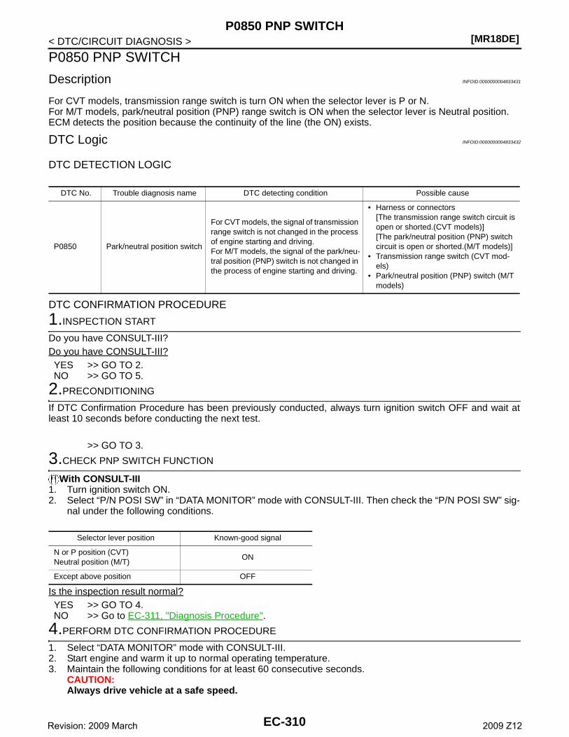
[MR18DE]P0850 PNP SWITCH
< DTC/CIRCUIT DIAGNOSIS >
P0850 PNP SWITCH
Description INFOID:0000000004833431
For CVT models, transmission range switch is turn ON when the selector lever is P or N.For M/T models, park/neutral position (PNP) range switch is ON when the selector lever is Neutral position.ECM detects the position because the continuity of the line (the ON) exists.
DTC Logic INFOID:0000000004833432
DTC DETECTION LOGIC
DTC CONFIRMATION PROCEDURE
1.INSPECTION START
Do you have CONSULT-III?Do you have CONSULT-III?YES >> GO TO 2.NO >> GO TO 5.
2.PRECONDITIONING
If DTC Confirmation Procedure has been previously conducted, always turn ignition switch OFF and wait atleast 10 seconds before conducting the next test.
>> GO TO 3.
3.CHECK PNP SWITCH FUNCTION
With CONSULT-III1. Turn ignition switch ON.2. Select “P/N POSI SW” in “DATA MONITOR” mode with CONSULT-III. Then check the “P/N POSI SW” sig-
nal under the following conditions.
Is the inspection result normal?YES >> GO TO 4.NO >> Go to EC-311, "Diagnosis Procedure".
4.PERFORM DTC CONFIRMATION PROCEDURE
1. Select “DATA MONITOR” mode with CONSULT-III.2. Start engine and warm it up to normal operating temperature.3. Maintain the following conditions for at least 60 consecutive seconds.
CAUTION:Always drive vehicle at a safe speed.
DTC No. Trouble diagnosis name DTC detecting condition Possible cause
P0850 Park/neutral position switch
For CVT models, the signal of transmission range switch is not changed in the process of engine starting and driving.For M/T models, the signal of the park/neu-tral position (PNP) switch is not changed in the process of engine starting and driving.
• Harness or connectors[The transmission range switch circuit is open or shorted.(CVT models)][The park/neutral position (PNP) switch circuit is open or shorted.(M/T models)]
• Transmission range switch (CVT mod-els)
• Park/neutral position (PNP) switch (M/T models)
Selector lever position Known-good signal
N or P position (CVT)Neutral position (M/T)
ON
Except above position OFF
EC-310Revision: 2009 March 2009 Z12
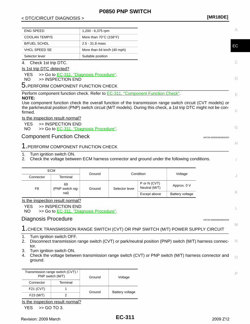
P0850 PNP SWITCH[MR18DE]
C
D
E
F
G
H
I
J
K
L
M
A
C
N
P
O
< DTC/CIRCUIT DIAGNOSIS >
E
4. Check 1st trip DTC.Is 1st trip DTC detected?YES >> Go to EC-311, "Diagnosis Procedure".NO >> INSPECTION END
5.PERFORM COMPONENT FUNCTION CHECK
Perform component function check. Refer to EC-311, "Component Function Check".NOTE:Use component function check the overall function of the transmission range switch circuit (CVT models) orthe park/neutral position (PNP) switch circuit (M/T models). During this check, a 1st trip DTC might not be con-firmed.Is the inspection result normal?YES >> INSPECTION ENDNO >> Go to EC-311, "Diagnosis Procedure".
Component Function Check INFOID:0000000004833433
1.PERFORM COMPONENT FUNCTION CHECK
1. Turn ignition switch ON.2. Check the voltage between ECM harness connector and ground under the following conditions.
Is the inspection result normal?YES >> INSPECTION ENDNO >> Go to EC-311, "Diagnosis Procedure".
Diagnosis Procedure INFOID:0000000004833435
1.CHECK TRANSMISSION RANGE SWITCH (CVT) OR PNP SWITCH (M/T) POWER SUPPLY CIRCUIT
1. Turn ignition switch OFF.2. Disconnect transmission range switch (CVT) or park/neutral position (PNP) switch (M/T) harness connec-
tor.3. Turn ignition switch ON.4. Check the voltage between transmission range switch (CVT) or PNP switch (M/T) harness connector and
ground.
Is the inspection result normal?YES >> GO TO 3.
ENG SPEED 1,200 - 6,375 rpm
COOLAN TEMP/S More than 70°C (158°F)
B/FUEL SCHDL 2.5 - 31.8 msec
VHCL SPEED SE More than 64 km/h (40 mph)
Selector lever Suitable position
ECMGround Condition Voltage
Connector Terminal
F869
(PNP switch sig-nal)
Ground Selector lever
P or N (CVT)Neutral (M/T)
Approx. 0 V
Except above Battery voltage
Transmission range switch (CVT) / PNP switch (M/T) Ground Voltage
Connector Terminal
F21 (CVT) 1Ground Battery voltage
F23 (M/T) 2
EC-311Revision: 2009 March 2009 Z12
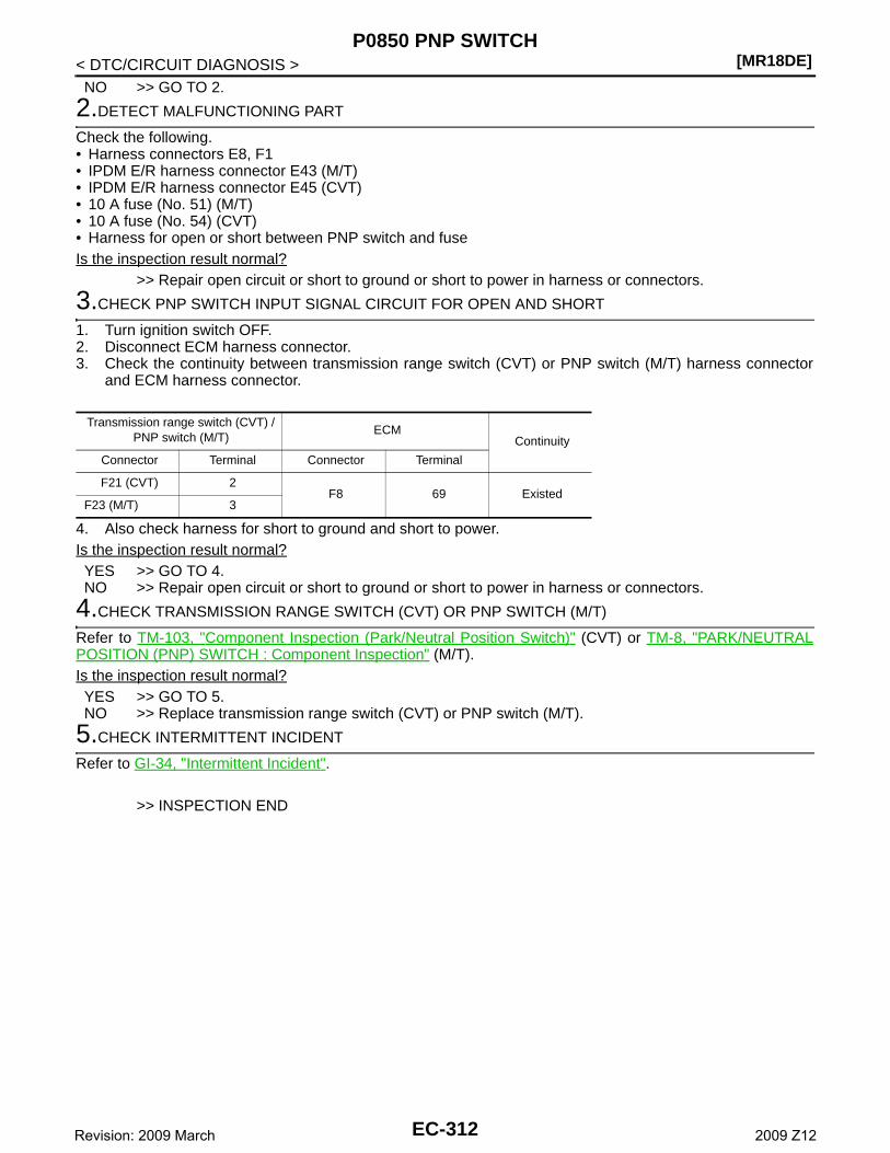
[MR18DE]P0850 PNP SWITCH
< DTC/CIRCUIT DIAGNOSIS >NO >> GO TO 2.
2.DETECT MALFUNCTIONING PART
Check the following.• Harness connectors E8, F1• IPDM E/R harness connector E43 (M/T)• IPDM E/R harness connector E45 (CVT)• 10 A fuse (No. 51) (M/T)• 10 A fuse (No. 54) (CVT)• Harness for open or short between PNP switch and fuseIs the inspection result normal?
>> Repair open circuit or short to ground or short to power in harness or connectors.
3.CHECK PNP SWITCH INPUT SIGNAL CIRCUIT FOR OPEN AND SHORT
1. Turn ignition switch OFF.2. Disconnect ECM harness connector.3. Check the continuity between transmission range switch (CVT) or PNP switch (M/T) harness connector
and ECM harness connector.
4. Also check harness for short to ground and short to power.Is the inspection result normal?YES >> GO TO 4.NO >> Repair open circuit or short to ground or short to power in harness or connectors.
4.CHECK TRANSMISSION RANGE SWITCH (CVT) OR PNP SWITCH (M/T)
Refer to TM-103, "Component Inspection (Park/Neutral Position Switch)" (CVT) or TM-8, "PARK/NEUTRALPOSITION (PNP) SWITCH : Component Inspection" (M/T).Is the inspection result normal?YES >> GO TO 5.NO >> Replace transmission range switch (CVT) or PNP switch (M/T).
5.CHECK INTERMITTENT INCIDENT
Refer to GI-34, "Intermittent Incident".
>> INSPECTION END
Transmission range switch (CVT) / PNP switch (M/T)
ECMContinuity
Connector Terminal Connector Terminal
F21 (CVT) 2F8 69 Existed
F23 (M/T) 3
EC-312Revision: 2009 March 2009 Z12
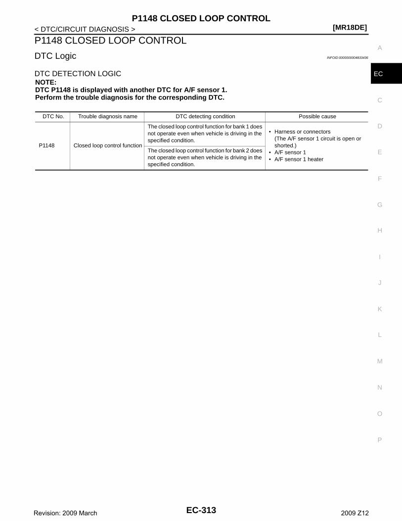
P1148 CLOSED LOOP CONTROL[MR18DE]
C
D
E
F
G
H
I
J
K
L
M
A
C
N
P
O
< DTC/CIRCUIT DIAGNOSIS >
E
P1148 CLOSED LOOP CONTROL
DTC Logic INFOID:0000000004833436
DTC DETECTION LOGICNOTE:DTC P1148 is displayed with another DTC for A/F sensor 1.Perform the trouble diagnosis for the corresponding DTC.
DTC No. Trouble diagnosis name DTC detecting condition Possible cause
P1148 Closed loop control function
The closed loop control function for bank 1 does not operate even when vehicle is driving in the specified condition.
• Harness or connectors(The A/F sensor 1 circuit is open or shorted.)
• A/F sensor 1• A/F sensor 1 heater
The closed loop control function for bank 2 does not operate even when vehicle is driving in the specified condition.
EC-313Revision: 2009 March 2009 Z12
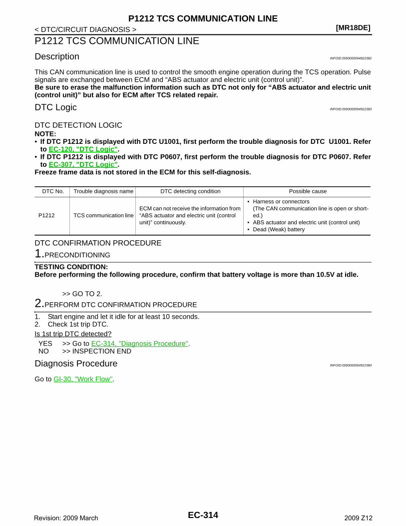
[MR18DE]P1212 TCS COMMUNICATION LINE
< DTC/CIRCUIT DIAGNOSIS >
P1212 TCS COMMUNICATION LINE
Description INFOID:0000000004922382
This CAN communication line is used to control the smooth engine operation during the TCS operation. Pulsesignals are exchanged between ECM and “ABS actuator and electric unit (control unit)”.Be sure to erase the malfunction information such as DTC not only for “ABS actuator and electric unit(control unit)” but also for ECM after TCS related repair.
DTC Logic INFOID:0000000004922383
DTC DETECTION LOGICNOTE:• If DTC P1212 is displayed with DTC U1001, first perform the trouble diagnosis for DTC U1001. Refer
to EC-120, "DTC Logic".• If DTC P1212 is displayed with DTC P0607, first perform the trouble diagnosis for DTC P0607. Refer
to EC-307, "DTC Logic".Freeze frame data is not stored in the ECM for this self-diagnosis.
DTC CONFIRMATION PROCEDURE
1.PRECONDITIONING
TESTING CONDITION:Before performing the following procedure, confirm that battery voltage is more than 10.5V at idle.
>> GO TO 2.
2.PERFORM DTC CONFIRMATION PROCEDURE
1. Start engine and let it idle for at least 10 seconds.2. Check 1st trip DTC.Is 1st trip DTC detected?YES >> Go to EC-314, "Diagnosis Procedure".NO >> INSPECTION END
Diagnosis Procedure INFOID:0000000004922384
Go to GI-30, "Work Flow".
DTC No. Trouble diagnosis name DTC detecting condition Possible cause
P1212 TCS communication lineECM can not receive the information from “ABS actuator and electric unit (control unit)” continuously.
• Harness or connectors(The CAN communication line is open or short-ed.)
• ABS actuator and electric unit (control unit)• Dead (Weak) battery
EC-314Revision: 2009 March 2009 Z12
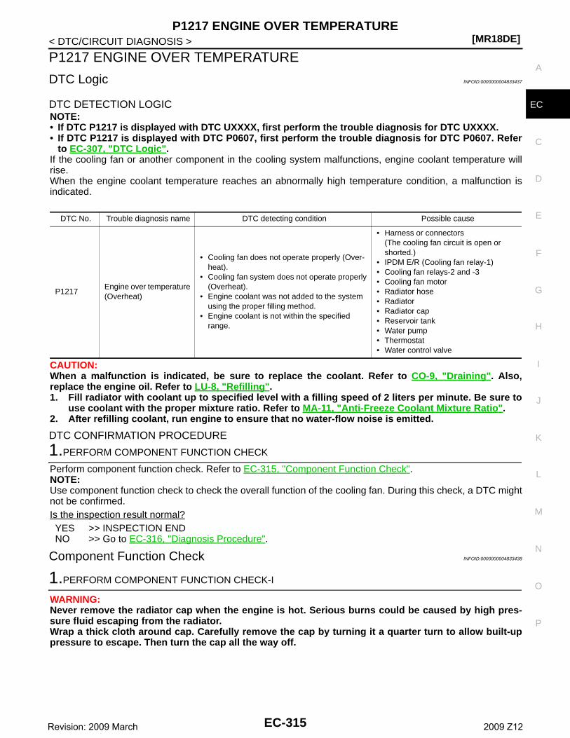
P1217 ENGINE OVER TEMPERATURE[MR18DE]
C
D
E
F
G
H
I
J
K
L
M
A
C
N
P
O
< DTC/CIRCUIT DIAGNOSIS >
E
P1217 ENGINE OVER TEMPERATURE
DTC Logic INFOID:0000000004833437
DTC DETECTION LOGICNOTE:• If DTC P1217 is displayed with DTC UXXXX, first perform the trouble diagnosis for DTC UXXXX.• If DTC P1217 is displayed with DTC P0607, first perform the trouble diagnosis for DTC P0607. Refer
to EC-307, "DTC Logic".If the cooling fan or another component in the cooling system malfunctions, engine coolant temperature willrise.When the engine coolant temperature reaches an abnormally high temperature condition, a malfunction isindicated.
CAUTION:When a malfunction is indicated, be sure to replace the coolant. Refer to CO-9, "Draining". Also,replace the engine oil. Refer to LU-8, "Refilling".1. Fill radiator with coolant up to specified level with a filling speed of 2 liters per minute. Be sure to
use coolant with the proper mixture ratio. Refer to MA-11, "Anti-Freeze Coolant Mixture Ratio".2. After refilling coolant, run engine to ensure that no water-flow noise is emitted.
DTC CONFIRMATION PROCEDURE
1.PERFORM COMPONENT FUNCTION CHECK
Perform component function check. Refer to EC-315, "Component Function Check".NOTE:Use component function check to check the overall function of the cooling fan. During this check, a DTC mightnot be confirmed.Is the inspection result normal?YES >> INSPECTION ENDNO >> Go to EC-316, "Diagnosis Procedure".
Component Function Check INFOID:0000000004833438
1.PERFORM COMPONENT FUNCTION CHECK-I
WARNING:Never remove the radiator cap when the engine is hot. Serious burns could be caused by high pres-sure fluid escaping from the radiator.Wrap a thick cloth around cap. Carefully remove the cap by turning it a quarter turn to allow built-uppressure to escape. Then turn the cap all the way off.
DTC No. Trouble diagnosis name DTC detecting condition Possible cause
P1217Engine over temperature (Overheat)
• Cooling fan does not operate properly (Over-heat).
• Cooling fan system does not operate properly (Overheat).
• Engine coolant was not added to the system using the proper filling method.
• Engine coolant is not within the specified range.
• Harness or connectors(The cooling fan circuit is open or shorted.)
• IPDM E/R (Cooling fan relay-1)• Cooling fan relays-2 and -3• Cooling fan motor• Radiator hose• Radiator• Radiator cap• Reservoir tank• Water pump• Thermostat• Water control valve
EC-315Revision: 2009 March 2009 Z12
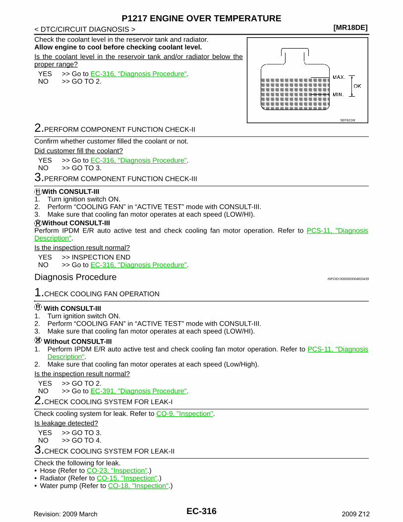
[MR18DE]P1217 ENGINE OVER TEMPERATURE
< DTC/CIRCUIT DIAGNOSIS >Check the coolant level in the reservoir tank and radiator.Allow engine to cool before checking coolant level.Is the coolant level in the reservoir tank and/or radiator below theproper range?YES >> Go to EC-316, "Diagnosis Procedure".NO >> GO TO 2.
2.PERFORM COMPONENT FUNCTION CHECK-II
Confirm whether customer filled the coolant or not.Did customer fill the coolant?YES >> Go to EC-316, "Diagnosis Procedure".NO >> GO TO 3.
3.PERFORM COMPONENT FUNCTION CHECK-III
With CONSULT-III1. Turn ignition switch ON.2. Perform “COOLING FAN” in “ACTIVE TEST” mode with CONSULT-III.3. Make sure that cooling fan motor operates at each speed (LOW/HI).
Without CONSULT-IIIPerform IPDM E/R auto active test and check cooling fan motor operation. Refer to PCS-11, "DiagnosisDescription".Is the inspection result normal?YES >> INSPECTION ENDNO >> Go to EC-316, "Diagnosis Procedure".
Diagnosis Procedure INFOID:0000000004833439
1.CHECK COOLING FAN OPERATION
With CONSULT-III1. Turn ignition switch ON.2. Perform “COOLING FAN” in “ACTIVE TEST” mode with CONSULT-III.3. Make sure that cooling fan motor operates at each speed (LOW/HI).
Without CONSULT-III1. Perform IPDM E/R auto active test and check cooling fan motor operation. Refer to PCS-11, "Diagnosis
Description".2. Make sure that cooling fan motor operates at each speed (Low/High).Is the inspection result normal?YES >> GO TO 2.NO >> Go to EC-391, "Diagnosis Procedure".
2.CHECK COOLING SYSTEM FOR LEAK-I
Check cooling system for leak. Refer to CO-9, "Inspection".Is leakage detected?YES >> GO TO 3.NO >> GO TO 4.
3.CHECK COOLING SYSTEM FOR LEAK-II
Check the following for leak.• Hose (Refer to CO-23, "Inspection".)• Radiator (Refer to CO-15, "Inspection".)• Water pump (Refer to CO-18, "Inspection".)
SEF621W
EC-316Revision: 2009 March 2009 Z12
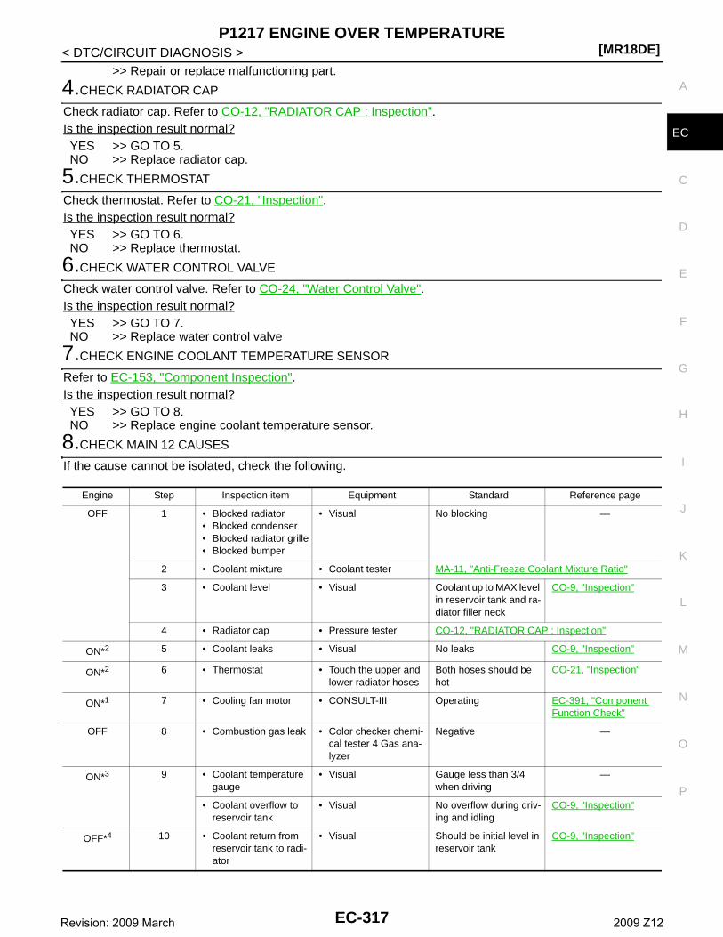
P1217 ENGINE OVER TEMPERATURE[MR18DE]
C
D
E
F
G
H
I
J
K
L
M
A
C
N
P
O
< DTC/CIRCUIT DIAGNOSIS >
E
>> Repair or replace malfunctioning part.
4.CHECK RADIATOR CAP
Check radiator cap. Refer to CO-12, "RADIATOR CAP : Inspection".Is the inspection result normal?YES >> GO TO 5.NO >> Replace radiator cap.
5.CHECK THERMOSTAT
Check thermostat. Refer to CO-21, "Inspection".Is the inspection result normal?YES >> GO TO 6.NO >> Replace thermostat.
6.CHECK WATER CONTROL VALVE
Check water control valve. Refer to CO-24, "Water Control Valve".Is the inspection result normal?YES >> GO TO 7.NO >> Replace water control valve
7.CHECK ENGINE COOLANT TEMPERATURE SENSOR
Refer to EC-153, "Component Inspection".Is the inspection result normal?YES >> GO TO 8.NO >> Replace engine coolant temperature sensor.
8.CHECK MAIN 12 CAUSES
If the cause cannot be isolated, check the following.
Engine Step Inspection item Equipment Standard Reference page
OFF 1 • Blocked radiator• Blocked condenser• Blocked radiator grille• Blocked bumper
• Visual No blocking —
2 • Coolant mixture • Coolant tester MA-11, "Anti-Freeze Coolant Mixture Ratio"
3 • Coolant level • Visual Coolant up to MAX level in reservoir tank and ra-diator filler neck
CO-9, "Inspection"
4 • Radiator cap • Pressure tester CO-12, "RADIATOR CAP : Inspection"
ON*2 5 • Coolant leaks • Visual No leaks CO-9, "Inspection"
ON*2 6 • Thermostat • Touch the upper and lower radiator hoses
Both hoses should be hot
CO-21, "Inspection"
ON*1 7 • Cooling fan motor • CONSULT-III Operating EC-391, "Component Function Check"
OFF 8 • Combustion gas leak • Color checker chemi-cal tester 4 Gas ana-lyzer
Negative —
ON*3 9 • Coolant temperature gauge
• Visual Gauge less than 3/4 when driving
—
• Coolant overflow to reservoir tank
• Visual No overflow during driv-ing and idling
CO-9, "Inspection"
OFF*4 10 • Coolant return from reservoir tank to radi-ator
• Visual Should be initial level in reservoir tank
CO-9, "Inspection"
EC-317Revision: 2009 March 2009 Z12
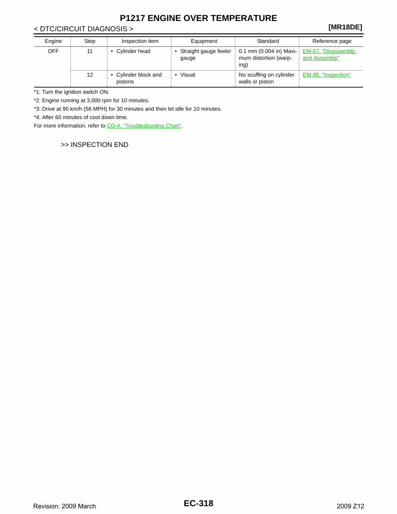
[MR18DE]P1217 ENGINE OVER TEMPERATURE
< DTC/CIRCUIT DIAGNOSIS >
*1: Turn the ignition switch ON.
*2: Engine running at 3,000 rpm for 10 minutes.
*3: Drive at 90 km/h (56 MPH) for 30 minutes and then let idle for 10 minutes.
*4: After 60 minutes of cool down time.
For more information, refer to CO-4, "Troubleshooting Chart".
>> INSPECTION END
OFF 11 • Cylinder head • Straight gauge feeler gauge
0.1 mm (0.004 in) Maxi-mum distortion (warp-ing)
EM-67, "Disassembly and Assembly"
12 • Cylinder block and pistons
• Visual No scuffing on cylinder walls or piston
EM-95, "Inspection"
Engine Step Inspection item Equipment Standard Reference page
EC-318Revision: 2009 March 2009 Z12
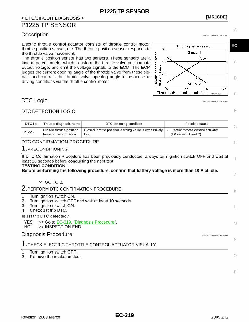
P1225 TP SENSOR[MR18DE]
C
D
E
F
G
H
I
J
K
L
M
A
C
N
P
O
< DTC/CIRCUIT DIAGNOSIS >
E
P1225 TP SENSOR
Description INFOID:0000000004833440
Electric throttle control actuator consists of throttle control motor,throttle position sensor, etc. The throttle position sensor responds tothe throttle valve movement. The throttle position sensor has two sensors. These sensors are akind of potentiometer which transform the throttle valve position intooutput voltage, and emit the voltage signals to the ECM. The ECMjudges the current opening angle of the throttle valve from these sig-nals and controls the throttle valve opening angle in response todriving conditions via the throttle control motor.
DTC Logic INFOID:0000000004833441
DTC DETECTION LOGIC
DTC CONFIRMATION PROCEDURE
1.PRECONDITIONING
If DTC Confirmation Procedure has been previously conducted, always turn ignition switch OFF and wait atleast 10 seconds before conducting the next test.TESTING CONDITION:Before performing the following procedure, confirm that battery voltage is more than 10 V at idle.
>> GO TO 2.
2.PERFORM DTC CONFIRMATION PROCEDURE
1. Turn ignition switch ON.2. Turn ignition switch OFF and wait at least 10 seconds.3. Turn ignition switch ON.4. Check 1st trip DTC.Is 1st trip DTC detected?YES >> Go to EC-319, "Diagnosis Procedure".NO >> INSPECTION END
Diagnosis Procedure INFOID:0000000004833442
1.CHECK ELECTRIC THROTTLE CONTROL ACTUATOR VISUALLY
1. Turn ignition switch OFF.2. Remove the intake air duct.
PBIB0145E
DTC No. Trouble diagnosis name DTC detecting condition Possible cause
P1225Closed throttle position learning performance
Closed throttle position learning value is excessively low.
• Electric throttle control actuator(TP sensor 1 and 2)
EC-319Revision: 2009 March 2009 Z12

[MR18DE]P1225 TP SENSOR
< DTC/CIRCUIT DIAGNOSIS >3. Check if foreign matter is caught between the throttle valve (1)
and the housing.- Electric throttle control actuator (2)Is the inspection result normal?YES >> GO TO 2.NO >> Remove the foreign matter and clean the electric throttle
control actuator inside.
2.REPLACE ELECTRIC THROTTLE CONTROL ACTUATOR
1. Replace electric throttle control actuator.2. Perform EC-320, "Special Repair Requirement".
>> INSPECTION END
Special Repair Requirement INFOID:0000000004833443
1.PERFORM THROTTLE VALVE CLOSED POSITION LEARNING
Refer to EC-17, "THROTTLE VALVE CLOSED POSITION LEARNING : Special Repair Requirement"
>> GO TO 2.
2.PERFORM IDLE AIR VOLUME LEARNING
Refer to EC-17, "IDLE AIR VOLUME LEARNING : Special Repair Requirement"
>> END
JMBIA2312ZZ
EC-320Revision: 2009 March 2009 Z12

P1226 TP SENSOR[MR18DE]
C
D
E
F
G
H
I
J
K
L
M
A
C
N
P
O
< DTC/CIRCUIT DIAGNOSIS >
E
P1226 TP SENSOR
Description INFOID:0000000004833444
Electric throttle control actuator consists of throttle control motor,throttle position sensor, etc. The throttle position sensor responds tothe throttle valve movement. The throttle position sensor has two sensors. These sensors are akind of potentiometer which transform the throttle valve position intooutput voltage, and emit the voltage signals to the ECM. The ECMjudges the current opening angle of the throttle valve from these sig-nals and controls the throttle valve opening angle in response todriving conditions via the throttle control motor.
DTC Logic INFOID:0000000004833445
DTC DETECTION LOGIC
DTC CONFIRMATION PROCEDURE
1.PRECONDITIONING
If DTC Confirmation Procedure has been previously conducted, always turn ignition switch OFF and wait atleast 10 seconds before conducting the next test.TESTING CONDITION:Before performing the following procedure, confirm that battery voltage is more than 10 V at idle.
>> GO TO 2.
2.PERFORM DTC CONFIRMATION PROCEDURE
1. Turn ignition switch ON.2. Turn ignition switch OFF, wait at least 10 seconds.3. Turn ignition switch ON.4. Repeat steps 2 and 3 for 32 times.5. Check 1st trip DTC.Is 1st trip DTC detected?YES >> Go to EC-321, "Diagnosis Procedure".NO >> INSPECTION END
Diagnosis Procedure INFOID:0000000004833446
1.CHECK ELECTRIC THROTTLE CONTROL ACTUATOR VISUALLY
1. Turn ignition switch OFF.2. Remove the intake air duct.
PBIB0145E
DTC No. Trouble diagnosis name DTC detecting condition Possible cause
P1226Closed throttle position learning performance
Closed throttle position learning is not performed successfully, repeatedly.
• Electric throttle control actuator(TP sensor 1 and 2)
EC-321Revision: 2009 March 2009 Z12
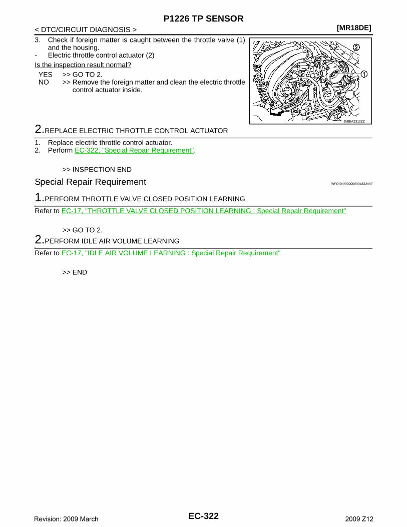
[MR18DE]P1226 TP SENSOR
< DTC/CIRCUIT DIAGNOSIS >3. Check if foreign matter is caught between the throttle valve (1)
and the housing.- Electric throttle control actuator (2)Is the inspection result normal?YES >> GO TO 2.NO >> Remove the foreign matter and clean the electric throttle
control actuator inside.
2.REPLACE ELECTRIC THROTTLE CONTROL ACTUATOR
1. Replace electric throttle control actuator.2. Perform EC-322, "Special Repair Requirement".
>> INSPECTION END
Special Repair Requirement INFOID:0000000004833447
1.PERFORM THROTTLE VALVE CLOSED POSITION LEARNING
Refer to EC-17, "THROTTLE VALVE CLOSED POSITION LEARNING : Special Repair Requirement"
>> GO TO 2.
2.PERFORM IDLE AIR VOLUME LEARNING
Refer to EC-17, "IDLE AIR VOLUME LEARNING : Special Repair Requirement"
>> END
JMBIA2312ZZ
EC-322Revision: 2009 March 2009 Z12
P1421 COLD START CONTROL[MR18DE]
C
D
E
F
G
H
I
J
K
L
M
A
C
N
P
O
< DTC/CIRCUIT DIAGNOSIS >
E
P1421 COLD START CONTROL
Description INFOID:0000000004833448
ECM controls ignition timing and engine idle speed when engine is started with pre-warming up condition.This control promotes the activation of three way catalyst by heating the catalyst and reduces emissions.
DTC Logic INFOID:0000000004833449
DTC DETECTION LOGICNOTE:If DTC P1421 is displayed with other DTC, first perform the trouble diagnosis for other DTC.
DTC CONFIRMATION PROCEDURE
1.PRECONDITIONING
If DTC Confirmation Procedure has been previously conducted, always turn ignition switch OFF and wait atleast 10 seconds before conducting the next test.TESTING CONDITION:Before performing the following procedure, confirm that battery voltage is more than 11 V at idle.
>> GO TO 2.
2.PERFORM DTC CONFIRMATION PROCEDURE
With CONSULT-III1. Turn ignition switch OFF and wait at least 10 seconds.2. Turn ignition switch ON.3. Select “DATA MONITOR” mode with CONSULT-III.4. Check that the “COOLAN TEMP/S” indication is between 4°C (39°F) and 36°C (97°F).
If “COOLAN TEMP/S” indication is within the specified value, go to the following step.If “COOLAN TEMP/S” indication is out of the specified value, cool engine down or warm engine up and goto step 1.
5. Start engine and let it idle for 5 minutes.6. Check 1st trip DTC.
With GSTFollow the procedure “With CONSULT-III” above.Is 1st trip DTC detected?YES >> Go to EC-323, "Diagnosis Procedure".NO >> INSPECTION END
Diagnosis Procedure INFOID:0000000004833450
1.PERFORM IDLE AIR VOLUME LEARNING
Perform EC-17, "IDLE AIR VOLUME LEARNING : Special Repair Requirement".Is Idle Air Volume Learning carried out successfully?YES >> GO TO 2.NO >> Follow the instruction of Idle Air Volume Learning.
2.CHECK INTAKE SYSTEM
Check for the cause of intake air volume lacking. Refer to the following.• Crushed intake air passage• Intake air passage clogging
DTC No. Trouble diagnosis name DTC detecting condition Possible cause
P1421Cold start emission reduction strategy monitoring
ECM does not control ignition timing and engine idle speed properly when engine is started with pre-warming up condition.
• Lack of intake air volume• Fuel injection system• ECM
EC-323Revision: 2009 March 2009 Z12
[MR18DE]P1421 COLD START CONTROL
< DTC/CIRCUIT DIAGNOSIS >Is the inspection result normal?YES >> GO TO 3.NO >> Repair or replace malfunctioning part
3.CHECK FUEL INJECTION SYSTEM FUNCTION
Perform DTC CONFIRMATION PROCEDURE for DTC P0171. Refer to EC-200, "DTC Logic".Is the inspection result normal?YES >> GO TO 4.NO >> Go to EC-201, "Diagnosis Procedure" for DTC P0171.
4.PERFORM DTC CONFIRMATION PROCEDURE
1. Turn ignition switch ON.2. Erase 1st trip DTC. Refer to “How to Erase DTC and 1st Trip DTC” in EC-85, "Diagnosis Description".3. Perform DTC CONFIRMATION PROCEDURE. Refer to EC-323, "DTC Logic".Is the 1st trip DTC P1421 displayed again?YES >> GO TO 5.NO >> INSPECTION END
5.REPLACE ECM
1. Replace ECM.2. Perform EC-15, "ADDITIONAL SERVICE WHEN REPLACING CONTROL UNIT : Special Repair Require-
ment".
>> INSPECTION END
EC-324Revision: 2009 March 2009 Z12
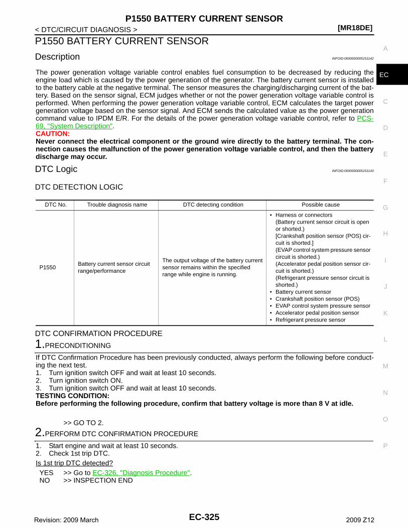
P1550 BATTERY CURRENT SENSOR[MR18DE]
C
D
E
F
G
H
I
J
K
L
M
A
C
N
P
O
< DTC/CIRCUIT DIAGNOSIS >
E
P1550 BATTERY CURRENT SENSOR
Description INFOID:0000000005151142
The power generation voltage variable control enables fuel consumption to be decreased by reducing theengine load which is caused by the power generation of the generator. The battery current sensor is installedto the battery cable at the negative terminal. The sensor measures the charging/discharging current of the bat-tery. Based on the sensor signal, ECM judges whether or not the power generation voltage variable control isperformed. When performing the power generation voltage variable control, ECM calculates the target powergeneration voltage based on the sensor signal. And ECM sends the calculated value as the power generationcommand value to IPDM E/R. For the details of the power generation voltage variable control, refer to PCS-69, "System Description".CAUTION:Never connect the electrical component or the ground wire directly to the battery terminal. The con-nection causes the malfunction of the power generation voltage variable control, and then the batterydischarge may occur.
DTC Logic INFOID:0000000005151143
DTC DETECTION LOGIC
DTC CONFIRMATION PROCEDURE
1.PRECONDITIONING
If DTC Confirmation Procedure has been previously conducted, always perform the following before conduct-ing the next test. 1. Turn ignition switch OFF and wait at least 10 seconds.2. Turn ignition switch ON.3. Turn ignition switch OFF and wait at least 10 seconds.TESTING CONDITION:Before performing the following procedure, confirm that battery voltage is more than 8 V at idle.
>> GO TO 2.
2.PERFORM DTC CONFIRMATION PROCEDURE
1. Start engine and wait at least 10 seconds.2. Check 1st trip DTC.Is 1st trip DTC detected?YES >> Go to EC-326, "Diagnosis Procedure".NO >> INSPECTION END
DTC No. Trouble diagnosis name DTC detecting condition Possible cause
P1550Battery current sensor circuit range/performance
The output voltage of the battery current sensor remains within the specified range while engine is running.
• Harness or connectors(Battery current sensor circuit is open or shorted.)[Crankshaft position sensor (POS) cir-cuit is shorted.](EVAP control system pressure sensor circuit is shorted.)(Accelerator pedal position sensor cir-cuit is shorted.)(Refrigerant pressure sensor circuit is shorted.)
• Battery current sensor• Crankshaft position sensor (POS)• EVAP control system pressure sensor• Accelerator pedal position sensor• Refrigerant pressure sensor
EC-325Revision: 2009 March 2009 Z12

[MR18DE]P1550 BATTERY CURRENT SENSOR
< DTC/CIRCUIT DIAGNOSIS >
Diagnosis Procedure INFOID:0000000005151144
1.CHECK GROUND CONNECTION
1. Turn ignition switch OFF.2. Check ground connection E38. Refer to Ground Inspection in GI-37, "Circuit Inspection".Is the inspection result normal?YES >> GO TO 2.NO >> Repair or replace ground connection.
2.CHECK BATTERY CURRENT SENSOR POWER SUPPLY CIRCUIT-I
1. Disconnect battery current sensor harness connector.2. Turn ignition switch ON.3. Check the voltage between battery current sensor harness connector and ground.
Is the inspection result normal?YES >> GO TO 8.NO >> GO TO 3.
3.CHECK BATTERY CURRENT SENSOR POWER SUPPLY CIRCUIT-II
1. Turn ignition switch OFF.2. Disconnect ECM harness connector.3. Check the continuity between battery current sensor harness connector and ECM harness connector.
Is the inspection result normal?YES >> GO TO 4.NO >> Repair open circuit.
4.CHECK SENSOR POWER SUPPLY CIRCUIT
Check harness for short to power and short to ground, between the following terminals.
Is the inspection result normal?YES >> GO TO 5.NO >> Repair short to ground or short to power in harness or connectors.
5.CHECK COMPONENTS
Check the following.• Crankshaft position sensor (POS) (Refer to EC-228, "Component Inspection".)• EVAP control system pressure sensor (Refer to EC-269, "Component Inspection".)• Refrigerant pressure sensor (Refer to EC-414, "Diagnosis Procedure".)
Battery current sensorGround Voltage
Connector Terminal
F53 1 Ground Approx. 5 V
Battery current sensor ECMContinuity
Connector Terminal Connector Terminal
F53 1 F8 77 Existed
ECM Sensor
Connector Terminal Name Connector Terminal
F8
74 Refrigerant pressure sensor E49 1
75 CKP sensor (POS) F20 1
76EVAP cotrol system pressure sen-sor
B21 3
77 Battery current sensor F53 1
E16 102 APP sensor E110 5
EC-326Revision: 2009 March 2009 Z12

P1550 BATTERY CURRENT SENSOR[MR18DE]
C
D
E
F
G
H
I
J
K
L
M
A
C
N
P
O
< DTC/CIRCUIT DIAGNOSIS >
E
Is the inspection result normal?YES >> GO TO 6.NO >> Replace malfunctioning components.
6.CHECK APP SENSOR
Refer to EC-381, "Component Inspection".Is the inspection result normal?YES >> GO TO 11.NO >> GO TO 7.
7.REPLACE ACCELERATOR PEDAL ASSEMBLY
1. Replace accelerator pedal assembly.2. Go to EC-381, "Special Repair Requirement".
>> INSPECTION END
8.CHECK BATTERY CURRENT SENSOR GROUND CIRCUIT FOR OPEN AND SHORT
1. Turn ignition switch OFF.2. Disconnect ECM harness connector.3. Check the continuity between battery current sensor harness connector and ECM harness connector.
4. Also check harness for short to ground and short to power.Is the inspection result normal?YES >> GO TO 9.NO >> Repair open circuit, short to ground or short to power in harness or connectors.
9.CHECK BATTERY CURRENT SENSOR INPUT SIGNAL CIRCUIT FOR OPEN AND SHORT
1. Check the continuity between battery current sensor harness connector and ECM harness connector.
2. Also check harness for short to ground and short to power.Is the inspection result normal?YES >> GO TO 10.NO >> Repair open circuit, short to ground or short to power in harness or connectors.
10.CHECK BATTERY CURRENT SENSOR
Refer to EC-327, "Component Inspection".Is the inspection result normal?YES >> GO TO 11.NO >> Replace battery negative cable assembly.
11.CHECK INTERMITTENT INCIDENT
Refer to GI-34, "Intermittent Incident".
>> INSPECTION END
Component Inspection INFOID:0000000005151145
1.CHECK BATTERY CURRENT SENSOR
Battery current sensor ECMContinuity
Connector Terminal Connector Terminal
F53 2 F8 68 Existed
Battery current sensor ECMContinuity
Connector Terminal Connector Terminal
F53 3 F8 58 Existed
EC-327Revision: 2009 March 2009 Z12
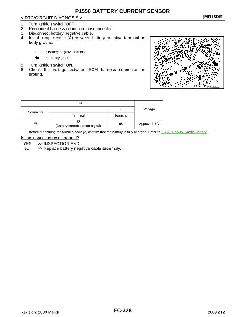
[MR18DE]P1550 BATTERY CURRENT SENSOR
< DTC/CIRCUIT DIAGNOSIS >1. Turn ignition switch OFF.2. Reconnect harness connectors disconnected.3. Disconnect battery negative cable.4. Install jumper cable (A) between battery negative terminal and
body ground.
5. Turn ignition switch ON.6. Check the voltage between ECM harness connector and
ground.
Before measuring the terminal voltage, confirm that the battery is fully charged. Refer to PG-3, "How to Handle Battery".
Is the inspection result normal?YES >> INSPECTION ENDNO >> Replace battery negative cable assembly.
1 : Battery negative terminal
: To body ground
JMBIA2313ZZ
ECM
VoltageConnector
+ -
Terminal Terminal
F858
(Battery current sensor signal)68 Approx. 2.5 V
EC-328Revision: 2009 March 2009 Z12
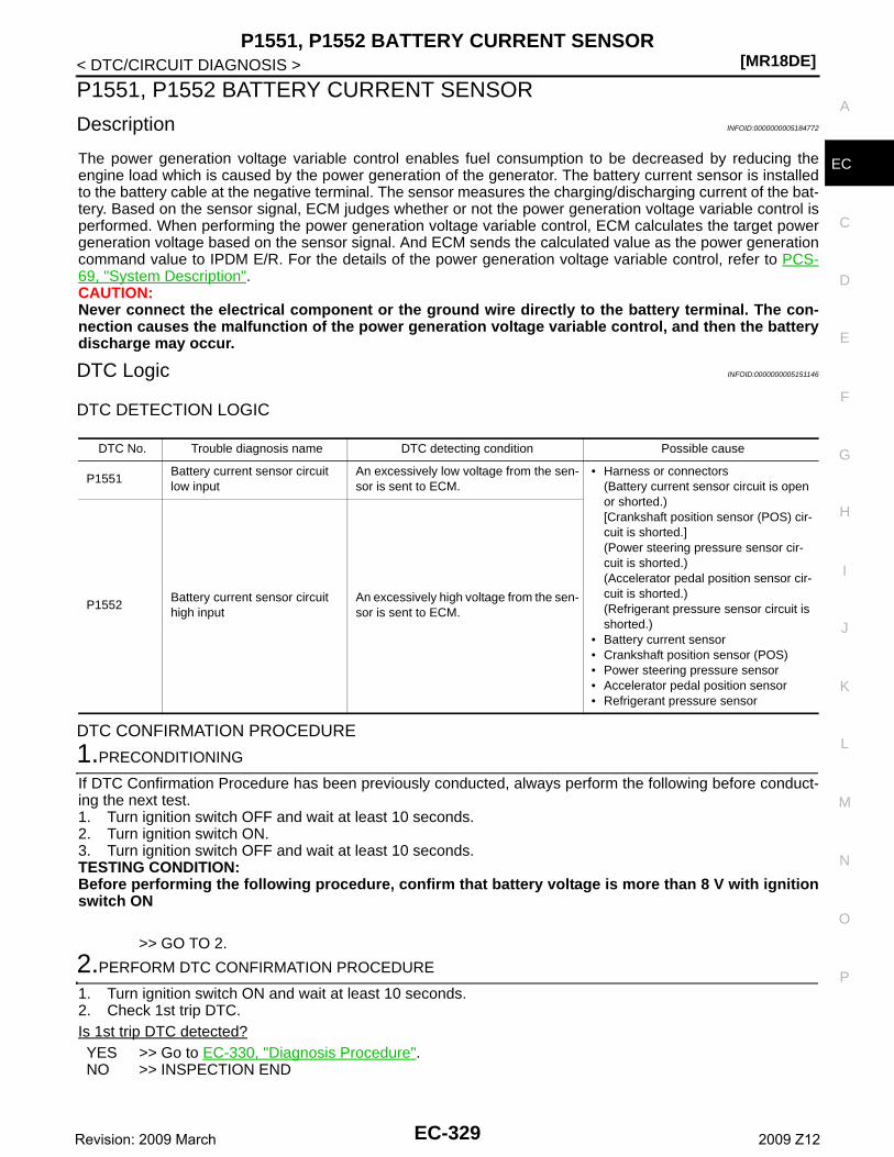
P1551, P1552 BATTERY CURRENT SENSOR[MR18DE]
C
D
E
F
G
H
I
J
K
L
M
A
C
N
P
O
< DTC/CIRCUIT DIAGNOSIS >
E
P1551, P1552 BATTERY CURRENT SENSOR
Description INFOID:0000000005184772
The power generation voltage variable control enables fuel consumption to be decreased by reducing theengine load which is caused by the power generation of the generator. The battery current sensor is installedto the battery cable at the negative terminal. The sensor measures the charging/discharging current of the bat-tery. Based on the sensor signal, ECM judges whether or not the power generation voltage variable control isperformed. When performing the power generation voltage variable control, ECM calculates the target powergeneration voltage based on the sensor signal. And ECM sends the calculated value as the power generationcommand value to IPDM E/R. For the details of the power generation voltage variable control, refer to PCS-69, "System Description".CAUTION:Never connect the electrical component or the ground wire directly to the battery terminal. The con-nection causes the malfunction of the power generation voltage variable control, and then the batterydischarge may occur.
DTC Logic INFOID:0000000005151146
DTC DETECTION LOGIC
DTC CONFIRMATION PROCEDURE
1.PRECONDITIONING
If DTC Confirmation Procedure has been previously conducted, always perform the following before conduct-ing the next test. 1. Turn ignition switch OFF and wait at least 10 seconds.2. Turn ignition switch ON.3. Turn ignition switch OFF and wait at least 10 seconds.TESTING CONDITION:Before performing the following procedure, confirm that battery voltage is more than 8 V with ignitionswitch ON
>> GO TO 2.
2.PERFORM DTC CONFIRMATION PROCEDURE
1. Turn ignition switch ON and wait at least 10 seconds.2. Check 1st trip DTC.Is 1st trip DTC detected?YES >> Go to EC-330, "Diagnosis Procedure".NO >> INSPECTION END
DTC No. Trouble diagnosis name DTC detecting condition Possible cause
P1551Battery current sensor circuit low input
An excessively low voltage from the sen-sor is sent to ECM.
• Harness or connectors(Battery current sensor circuit is open or shorted.)[Crankshaft position sensor (POS) cir-cuit is shorted.](Power steering pressure sensor cir-cuit is shorted.)(Accelerator pedal position sensor cir-cuit is shorted.)(Refrigerant pressure sensor circuit is shorted.)
• Battery current sensor• Crankshaft position sensor (POS)• Power steering pressure sensor• Accelerator pedal position sensor• Refrigerant pressure sensor
P1552Battery current sensor circuit high input
An excessively high voltage from the sen-sor is sent to ECM.
EC-329Revision: 2009 March 2009 Z12
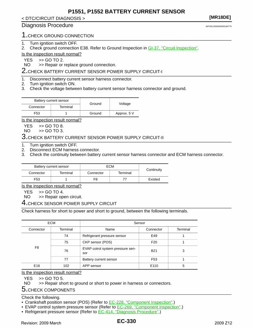
[MR18DE]P1551, P1552 BATTERY CURRENT SENSOR
< DTC/CIRCUIT DIAGNOSIS >
Diagnosis Procedure INFOID:0000000005184775
1.CHECK GROUND CONNECTION
1. Turn ignition switch OFF.2. Check ground connection E38. Refer to Ground Inspection in GI-37, "Circuit Inspection".Is the inspection result normal?YES >> GO TO 2.NO >> Repair or replace ground connection.
2.CHECK BATTERY CURRENT SENSOR POWER SUPPLY CIRCUIT-I
1. Disconnect battery current sensor harness connector.2. Turn ignition switch ON.3. Check the voltage between battery current sensor harness connector and ground.
Is the inspection result normal?YES >> GO TO 8.NO >> GO TO 3.
3.CHECK BATTERY CURRENT SENSOR POWER SUPPLY CIRCUIT-II
1. Turn ignition switch OFF.2. Disconnect ECM harness connector.3. Check the continuity between battery current sensor harness connector and ECM harness connector.
Is the inspection result normal?YES >> GO TO 4.NO >> Repair open circuit.
4.CHECK SENSOR POWER SUPPLY CIRCUIT
Check harness for short to power and short to ground, between the following terminals.
Is the inspection result normal?YES >> GO TO 5.NO >> Repair short to ground or short to power in harness or connectors.
5.CHECK COMPONENTS
Check the following.• Crankshaft position sensor (POS) (Refer to EC-228, "Component Inspection".)• EVAP control system pressure sensor (Refer to EC-269, "Component Inspection".)• Refrigerant pressure sensor (Refer to EC-414, "Diagnosis Procedure".)
Battery current sensorGround Voltage
Connector Terminal
F53 1 Ground Approx. 5 V
Battery current sensor ECMContinuity
Connector Terminal Connector Terminal
F53 1 F8 77 Existed
ECM Sensor
Connector Terminal Name Connector Terminal
F8
74 Refrigerant pressure sensor E49 1
75 CKP sensor (POS) F20 1
76EVAP cotrol system pressure sen-sor
B21 3
77 Battery current sensor F53 1
E16 102 APP sensor E110 5
EC-330Revision: 2009 March 2009 Z12
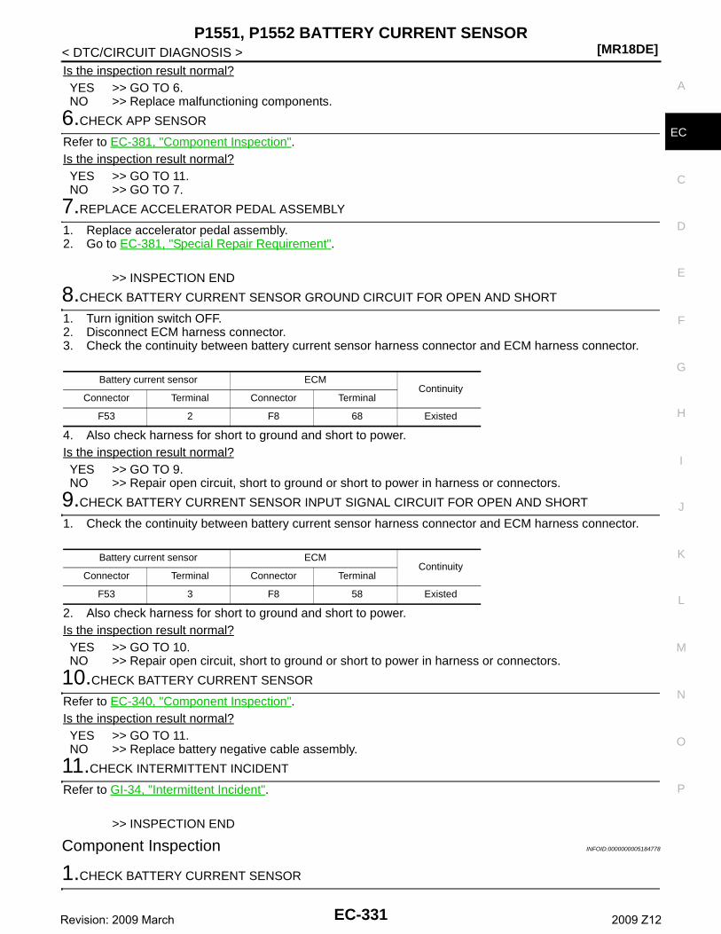
P1551, P1552 BATTERY CURRENT SENSOR[MR18DE]
C
D
E
F
G
H
I
J
K
L
M
A
C
N
P
O
< DTC/CIRCUIT DIAGNOSIS >
E
Is the inspection result normal?YES >> GO TO 6.NO >> Replace malfunctioning components.
6.CHECK APP SENSOR
Refer to EC-381, "Component Inspection".Is the inspection result normal?YES >> GO TO 11.NO >> GO TO 7.
7.REPLACE ACCELERATOR PEDAL ASSEMBLY
1. Replace accelerator pedal assembly.2. Go to EC-381, "Special Repair Requirement".
>> INSPECTION END
8.CHECK BATTERY CURRENT SENSOR GROUND CIRCUIT FOR OPEN AND SHORT
1. Turn ignition switch OFF.2. Disconnect ECM harness connector.3. Check the continuity between battery current sensor harness connector and ECM harness connector.
4. Also check harness for short to ground and short to power.Is the inspection result normal?YES >> GO TO 9.NO >> Repair open circuit, short to ground or short to power in harness or connectors.
9.CHECK BATTERY CURRENT SENSOR INPUT SIGNAL CIRCUIT FOR OPEN AND SHORT
1. Check the continuity between battery current sensor harness connector and ECM harness connector.
2. Also check harness for short to ground and short to power.Is the inspection result normal?YES >> GO TO 10.NO >> Repair open circuit, short to ground or short to power in harness or connectors.
10.CHECK BATTERY CURRENT SENSOR
Refer to EC-340, "Component Inspection".Is the inspection result normal?YES >> GO TO 11.NO >> Replace battery negative cable assembly.
11.CHECK INTERMITTENT INCIDENT
Refer to GI-34, "Intermittent Incident".
>> INSPECTION END
Component Inspection INFOID:0000000005184778
1.CHECK BATTERY CURRENT SENSOR
Battery current sensor ECMContinuity
Connector Terminal Connector Terminal
F53 2 F8 68 Existed
Battery current sensor ECMContinuity
Connector Terminal Connector Terminal
F53 3 F8 58 Existed
EC-331Revision: 2009 March 2009 Z12
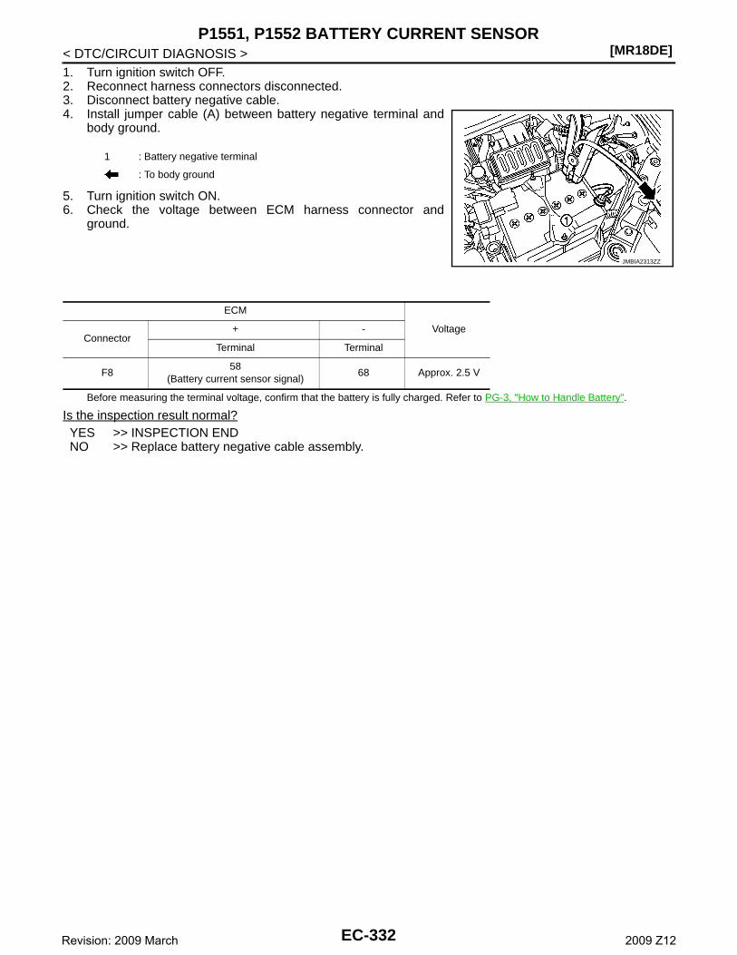
[MR18DE]P1551, P1552 BATTERY CURRENT SENSOR
< DTC/CIRCUIT DIAGNOSIS >1. Turn ignition switch OFF.2. Reconnect harness connectors disconnected.3. Disconnect battery negative cable.4. Install jumper cable (A) between battery negative terminal and
body ground.
5. Turn ignition switch ON.6. Check the voltage between ECM harness connector and
ground.
Before measuring the terminal voltage, confirm that the battery is fully charged. Refer to PG-3, "How to Handle Battery".
Is the inspection result normal?YES >> INSPECTION ENDNO >> Replace battery negative cable assembly.
1 : Battery negative terminal
: To body ground
JMBIA2313ZZ
ECM
VoltageConnector
+ -
Terminal Terminal
F858
(Battery current sensor signal)68 Approx. 2.5 V
EC-332Revision: 2009 March 2009 Z12
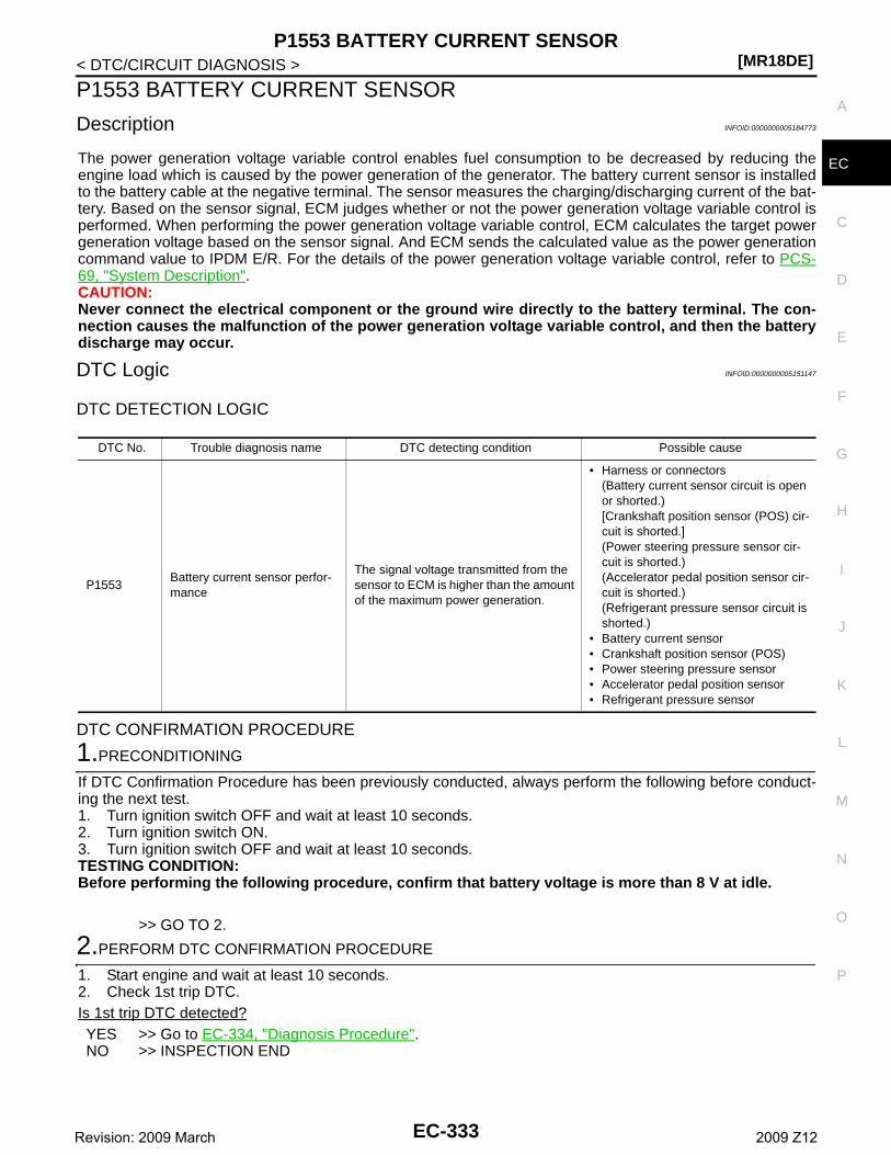
P1553 BATTERY CURRENT SENSOR[MR18DE]
C
D
E
F
G
H
I
J
K
L
M
A
C
N
P
O
< DTC/CIRCUIT DIAGNOSIS >
E
P1553 BATTERY CURRENT SENSOR
Description INFOID:0000000005184773
The power generation voltage variable control enables fuel consumption to be decreased by reducing theengine load which is caused by the power generation of the generator. The battery current sensor is installedto the battery cable at the negative terminal. The sensor measures the charging/discharging current of the bat-tery. Based on the sensor signal, ECM judges whether or not the power generation voltage variable control isperformed. When performing the power generation voltage variable control, ECM calculates the target powergeneration voltage based on the sensor signal. And ECM sends the calculated value as the power generationcommand value to IPDM E/R. For the details of the power generation voltage variable control, refer to PCS-69, "System Description".CAUTION:Never connect the electrical component or the ground wire directly to the battery terminal. The con-nection causes the malfunction of the power generation voltage variable control, and then the batterydischarge may occur.
DTC Logic INFOID:0000000005151147
DTC DETECTION LOGIC
DTC CONFIRMATION PROCEDURE
1.PRECONDITIONING
If DTC Confirmation Procedure has been previously conducted, always perform the following before conduct-ing the next test. 1. Turn ignition switch OFF and wait at least 10 seconds.2. Turn ignition switch ON.3. Turn ignition switch OFF and wait at least 10 seconds.TESTING CONDITION:Before performing the following procedure, confirm that battery voltage is more than 8 V at idle.
>> GO TO 2.
2.PERFORM DTC CONFIRMATION PROCEDURE
1. Start engine and wait at least 10 seconds.2. Check 1st trip DTC.Is 1st trip DTC detected?YES >> Go to EC-334, "Diagnosis Procedure".NO >> INSPECTION END
DTC No. Trouble diagnosis name DTC detecting condition Possible cause
P1553Battery current sensor perfor-mance
The signal voltage transmitted from the sensor to ECM is higher than the amount of the maximum power generation.
• Harness or connectors(Battery current sensor circuit is open or shorted.)[Crankshaft position sensor (POS) cir-cuit is shorted.](Power steering pressure sensor cir-cuit is shorted.)(Accelerator pedal position sensor cir-cuit is shorted.)(Refrigerant pressure sensor circuit is shorted.)
• Battery current sensor• Crankshaft position sensor (POS)• Power steering pressure sensor• Accelerator pedal position sensor• Refrigerant pressure sensor
EC-333Revision: 2009 March 2009 Z12
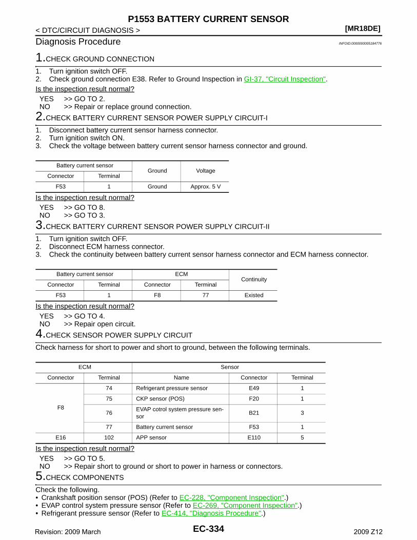
[MR18DE]P1553 BATTERY CURRENT SENSOR
< DTC/CIRCUIT DIAGNOSIS >
Diagnosis Procedure INFOID:0000000005184776
1.CHECK GROUND CONNECTION
1. Turn ignition switch OFF.2. Check ground connection E38. Refer to Ground Inspection in GI-37, "Circuit Inspection".Is the inspection result normal?YES >> GO TO 2.NO >> Repair or replace ground connection.
2.CHECK BATTERY CURRENT SENSOR POWER SUPPLY CIRCUIT-I
1. Disconnect battery current sensor harness connector.2. Turn ignition switch ON.3. Check the voltage between battery current sensor harness connector and ground.
Is the inspection result normal?YES >> GO TO 8.NO >> GO TO 3.
3.CHECK BATTERY CURRENT SENSOR POWER SUPPLY CIRCUIT-II
1. Turn ignition switch OFF.2. Disconnect ECM harness connector.3. Check the continuity between battery current sensor harness connector and ECM harness connector.
Is the inspection result normal?YES >> GO TO 4.NO >> Repair open circuit.
4.CHECK SENSOR POWER SUPPLY CIRCUIT
Check harness for short to power and short to ground, between the following terminals.
Is the inspection result normal?YES >> GO TO 5.NO >> Repair short to ground or short to power in harness or connectors.
5.CHECK COMPONENTS
Check the following.• Crankshaft position sensor (POS) (Refer to EC-228, "Component Inspection".)• EVAP control system pressure sensor (Refer to EC-269, "Component Inspection".)• Refrigerant pressure sensor (Refer to EC-414, "Diagnosis Procedure".)
Battery current sensorGround Voltage
Connector Terminal
F53 1 Ground Approx. 5 V
Battery current sensor ECMContinuity
Connector Terminal Connector Terminal
F53 1 F8 77 Existed
ECM Sensor
Connector Terminal Name Connector Terminal
F8
74 Refrigerant pressure sensor E49 1
75 CKP sensor (POS) F20 1
76EVAP cotrol system pressure sen-sor
B21 3
77 Battery current sensor F53 1
E16 102 APP sensor E110 5
EC-334Revision: 2009 March 2009 Z12
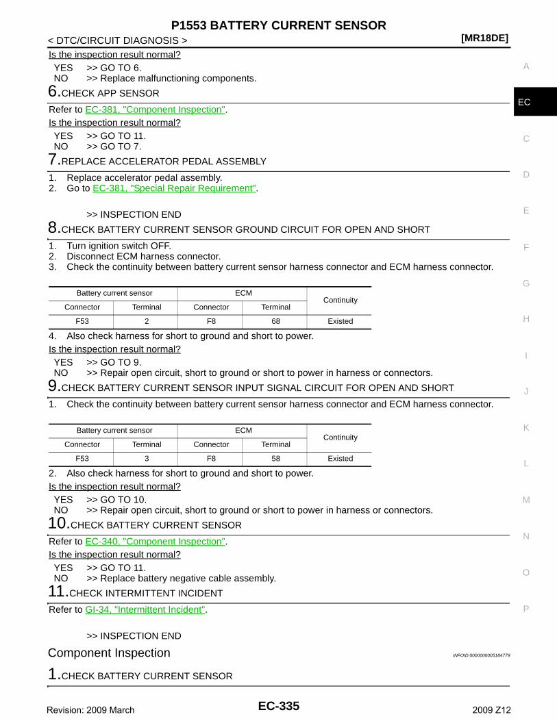
P1553 BATTERY CURRENT SENSOR[MR18DE]
C
D
E
F
G
H
I
J
K
L
M
A
C
N
P
O
< DTC/CIRCUIT DIAGNOSIS >
E
Is the inspection result normal?YES >> GO TO 6.NO >> Replace malfunctioning components.
6.CHECK APP SENSOR
Refer to EC-381, "Component Inspection".Is the inspection result normal?YES >> GO TO 11.NO >> GO TO 7.
7.REPLACE ACCELERATOR PEDAL ASSEMBLY
1. Replace accelerator pedal assembly.2. Go to EC-381, "Special Repair Requirement".
>> INSPECTION END
8.CHECK BATTERY CURRENT SENSOR GROUND CIRCUIT FOR OPEN AND SHORT
1. Turn ignition switch OFF.2. Disconnect ECM harness connector.3. Check the continuity between battery current sensor harness connector and ECM harness connector.
4. Also check harness for short to ground and short to power.Is the inspection result normal?YES >> GO TO 9.NO >> Repair open circuit, short to ground or short to power in harness or connectors.
9.CHECK BATTERY CURRENT SENSOR INPUT SIGNAL CIRCUIT FOR OPEN AND SHORT
1. Check the continuity between battery current sensor harness connector and ECM harness connector.
2. Also check harness for short to ground and short to power.Is the inspection result normal?YES >> GO TO 10.NO >> Repair open circuit, short to ground or short to power in harness or connectors.
10.CHECK BATTERY CURRENT SENSOR
Refer to EC-340, "Component Inspection".Is the inspection result normal?YES >> GO TO 11.NO >> Replace battery negative cable assembly.
11.CHECK INTERMITTENT INCIDENT
Refer to GI-34, "Intermittent Incident".
>> INSPECTION END
Component Inspection INFOID:0000000005184779
1.CHECK BATTERY CURRENT SENSOR
Battery current sensor ECMContinuity
Connector Terminal Connector Terminal
F53 2 F8 68 Existed
Battery current sensor ECMContinuity
Connector Terminal Connector Terminal
F53 3 F8 58 Existed
EC-335Revision: 2009 March 2009 Z12

[MR18DE]P1553 BATTERY CURRENT SENSOR
< DTC/CIRCUIT DIAGNOSIS >1. Turn ignition switch OFF.2. Reconnect harness connectors disconnected.3. Disconnect battery negative cable.4. Install jumper cable (A) between battery negative terminal and
body ground.
5. Turn ignition switch ON.6. Check the voltage between ECM harness connector and
ground.
Before measuring the terminal voltage, confirm that the battery is fully charged. Refer to PG-3, "How to Handle Battery".
Is the inspection result normal?YES >> INSPECTION ENDNO >> Replace battery negative cable assembly.
1 : Battery negative terminal
: To body ground
JMBIA2313ZZ
ECM
VoltageConnector
+ -
Terminal Terminal
F858
(Battery current sensor signal)68 Approx. 2.5 V
EC-336Revision: 2009 March 2009 Z12
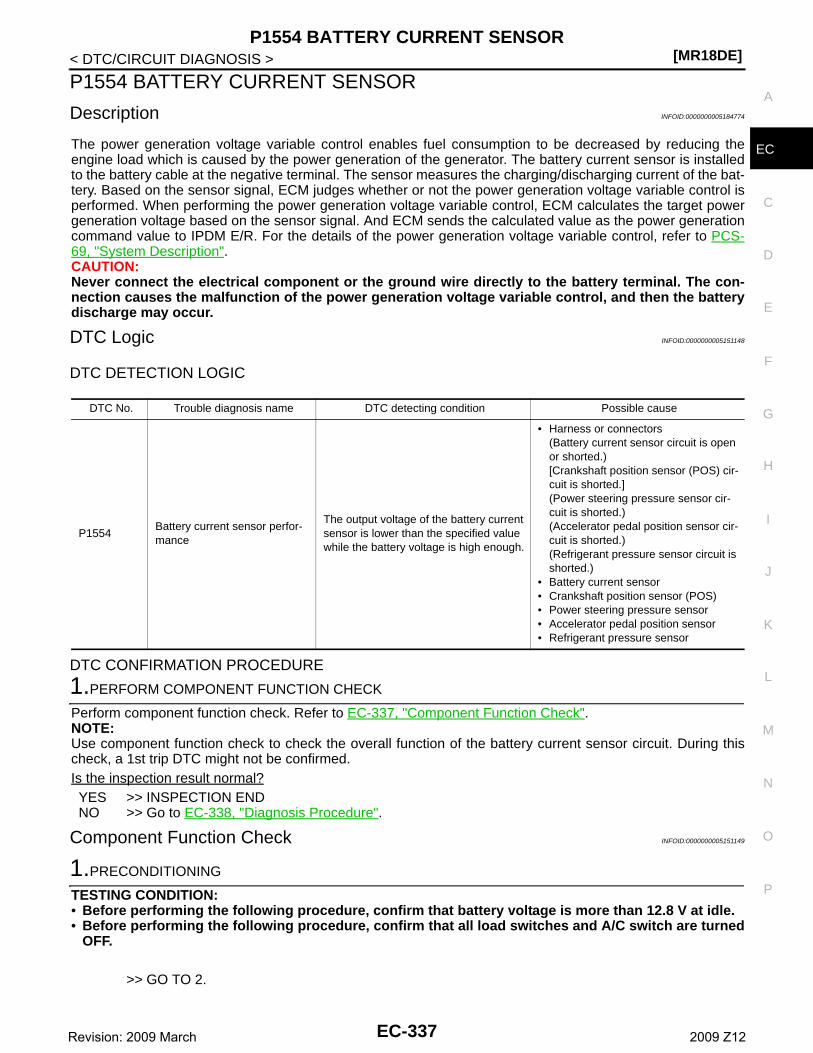
P1554 BATTERY CURRENT SENSOR[MR18DE]
C
D
E
F
G
H
I
J
K
L
M
A
C
N
P
O
< DTC/CIRCUIT DIAGNOSIS >
E
P1554 BATTERY CURRENT SENSOR
Description INFOID:0000000005184774
The power generation voltage variable control enables fuel consumption to be decreased by reducing theengine load which is caused by the power generation of the generator. The battery current sensor is installedto the battery cable at the negative terminal. The sensor measures the charging/discharging current of the bat-tery. Based on the sensor signal, ECM judges whether or not the power generation voltage variable control isperformed. When performing the power generation voltage variable control, ECM calculates the target powergeneration voltage based on the sensor signal. And ECM sends the calculated value as the power generationcommand value to IPDM E/R. For the details of the power generation voltage variable control, refer to PCS-69, "System Description".CAUTION:Never connect the electrical component or the ground wire directly to the battery terminal. The con-nection causes the malfunction of the power generation voltage variable control, and then the batterydischarge may occur.
DTC Logic INFOID:0000000005151148
DTC DETECTION LOGIC
DTC CONFIRMATION PROCEDURE
1.PERFORM COMPONENT FUNCTION CHECK
Perform component function check. Refer to EC-337, "Component Function Check".NOTE:Use component function check to check the overall function of the battery current sensor circuit. During thischeck, a 1st trip DTC might not be confirmed.Is the inspection result normal?YES >> INSPECTION ENDNO >> Go to EC-338, "Diagnosis Procedure".
Component Function Check INFOID:0000000005151149
1.PRECONDITIONING
TESTING CONDITION:• Before performing the following procedure, confirm that battery voltage is more than 12.8 V at idle.• Before performing the following procedure, confirm that all load switches and A/C switch are turned
OFF.
>> GO TO 2.
DTC No. Trouble diagnosis name DTC detecting condition Possible cause
P1554Battery current sensor perfor-mance
The output voltage of the battery current sensor is lower than the specified value while the battery voltage is high enough.
• Harness or connectors(Battery current sensor circuit is open or shorted.)[Crankshaft position sensor (POS) cir-cuit is shorted.](Power steering pressure sensor cir-cuit is shorted.)(Accelerator pedal position sensor cir-cuit is shorted.)(Refrigerant pressure sensor circuit is shorted.)
• Battery current sensor• Crankshaft position sensor (POS)• Power steering pressure sensor• Accelerator pedal position sensor• Refrigerant pressure sensor
EC-337Revision: 2009 March 2009 Z12
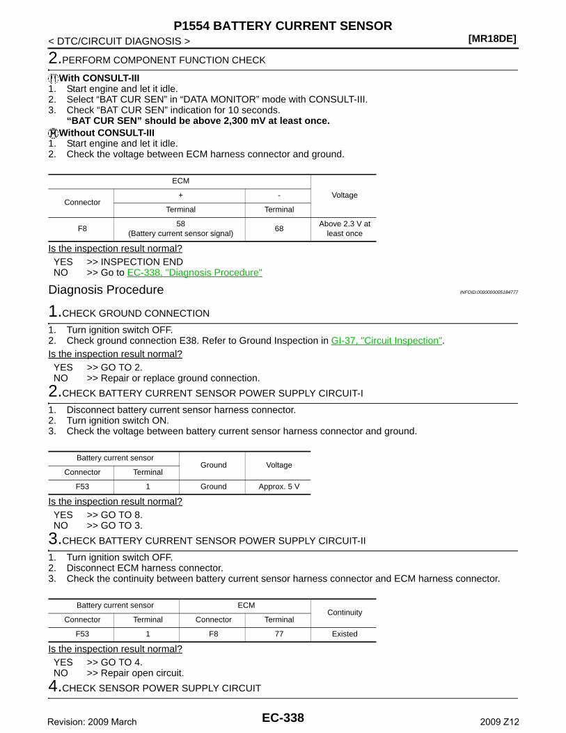
[MR18DE]P1554 BATTERY CURRENT SENSOR
< DTC/CIRCUIT DIAGNOSIS >
2.PERFORM COMPONENT FUNCTION CHECK
With CONSULT-III1. Start engine and let it idle.2. Select “BAT CUR SEN” in “DATA MONITOR” mode with CONSULT-III.3. Check “BAT CUR SEN” indication for 10 seconds.
“BAT CUR SEN” should be above 2,300 mV at least once.Without CONSULT-III
1. Start engine and let it idle.2. Check the voltage between ECM harness connector and ground.
Is the inspection result normal?YES >> INSPECTION ENDNO >> Go to EC-338, "Diagnosis Procedure"
Diagnosis Procedure INFOID:0000000005184777
1.CHECK GROUND CONNECTION
1. Turn ignition switch OFF.2. Check ground connection E38. Refer to Ground Inspection in GI-37, "Circuit Inspection".Is the inspection result normal?YES >> GO TO 2.NO >> Repair or replace ground connection.
2.CHECK BATTERY CURRENT SENSOR POWER SUPPLY CIRCUIT-I
1. Disconnect battery current sensor harness connector.2. Turn ignition switch ON.3. Check the voltage between battery current sensor harness connector and ground.
Is the inspection result normal?YES >> GO TO 8.NO >> GO TO 3.
3.CHECK BATTERY CURRENT SENSOR POWER SUPPLY CIRCUIT-II
1. Turn ignition switch OFF.2. Disconnect ECM harness connector.3. Check the continuity between battery current sensor harness connector and ECM harness connector.
Is the inspection result normal?YES >> GO TO 4.NO >> Repair open circuit.
4.CHECK SENSOR POWER SUPPLY CIRCUIT
ECM
VoltageConnector
+ -
Terminal Terminal
F858
(Battery current sensor signal)68
Above 2.3 V at least once
Battery current sensorGround Voltage
Connector Terminal
F53 1 Ground Approx. 5 V
Battery current sensor ECMContinuity
Connector Terminal Connector Terminal
F53 1 F8 77 Existed
EC-338Revision: 2009 March 2009 Z12
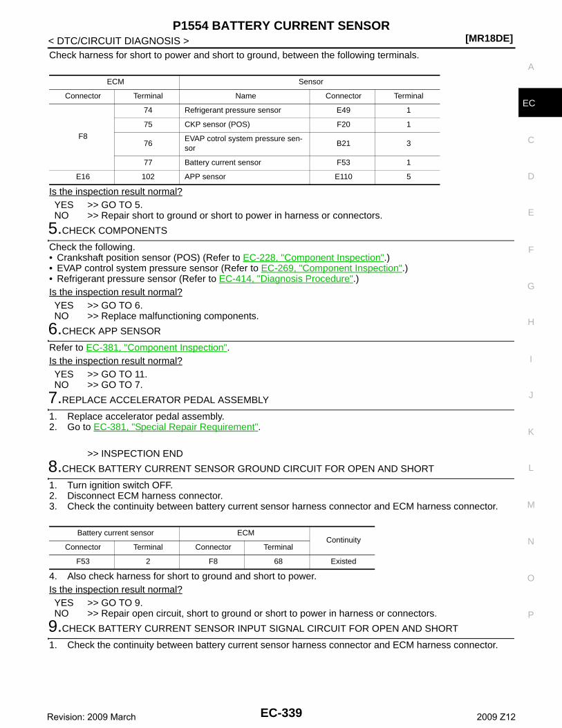
P1554 BATTERY CURRENT SENSOR[MR18DE]
C
D
E
F
G
H
I
J
K
L
M
A
C
N
P
O
< DTC/CIRCUIT DIAGNOSIS >
E
Check harness for short to power and short to ground, between the following terminals.
Is the inspection result normal?YES >> GO TO 5.NO >> Repair short to ground or short to power in harness or connectors.
5.CHECK COMPONENTS
Check the following.• Crankshaft position sensor (POS) (Refer to EC-228, "Component Inspection".)• EVAP control system pressure sensor (Refer to EC-269, "Component Inspection".)• Refrigerant pressure sensor (Refer to EC-414, "Diagnosis Procedure".)Is the inspection result normal?YES >> GO TO 6.NO >> Replace malfunctioning components.
6.CHECK APP SENSOR
Refer to EC-381, "Component Inspection".Is the inspection result normal?YES >> GO TO 11.NO >> GO TO 7.
7.REPLACE ACCELERATOR PEDAL ASSEMBLY
1. Replace accelerator pedal assembly.2. Go to EC-381, "Special Repair Requirement".
>> INSPECTION END
8.CHECK BATTERY CURRENT SENSOR GROUND CIRCUIT FOR OPEN AND SHORT
1. Turn ignition switch OFF.2. Disconnect ECM harness connector.3. Check the continuity between battery current sensor harness connector and ECM harness connector.
4. Also check harness for short to ground and short to power.Is the inspection result normal?YES >> GO TO 9.NO >> Repair open circuit, short to ground or short to power in harness or connectors.
9.CHECK BATTERY CURRENT SENSOR INPUT SIGNAL CIRCUIT FOR OPEN AND SHORT
1. Check the continuity between battery current sensor harness connector and ECM harness connector.
ECM Sensor
Connector Terminal Name Connector Terminal
F8
74 Refrigerant pressure sensor E49 1
75 CKP sensor (POS) F20 1
76EVAP cotrol system pressure sen-sor
B21 3
77 Battery current sensor F53 1
E16 102 APP sensor E110 5
Battery current sensor ECMContinuity
Connector Terminal Connector Terminal
F53 2 F8 68 Existed
EC-339Revision: 2009 March 2009 Z12
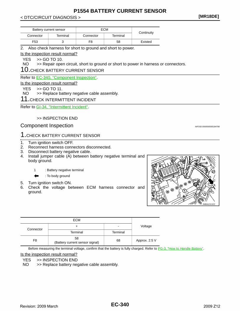
[MR18DE]P1554 BATTERY CURRENT SENSOR
< DTC/CIRCUIT DIAGNOSIS >
2. Also check harness for short to ground and short to power.Is the inspection result normal?YES >> GO TO 10.NO >> Repair open circuit, short to ground or short to power in harness or connectors.
10.CHECK BATTERY CURRENT SENSOR
Refer to EC-340, "Component Inspection".Is the inspection result normal?YES >> GO TO 11.NO >> Replace battery negative cable assembly.
11.CHECK INTERMITTENT INCIDENT
Refer to GI-34, "Intermittent Incident".
>> INSPECTION END
Component Inspection INFOID:0000000005184780
1.CHECK BATTERY CURRENT SENSOR
1. Turn ignition switch OFF.2. Reconnect harness connectors disconnected.3. Disconnect battery negative cable.4. Install jumper cable (A) between battery negative terminal and
body ground.
5. Turn ignition switch ON.6. Check the voltage between ECM harness connector and
ground.
Before measuring the terminal voltage, confirm that the battery is fully charged. Refer to PG-3, "How to Handle Battery".
Is the inspection result normal?YES >> INSPECTION ENDNO >> Replace battery negative cable assembly.
Battery current sensor ECMContinuity
Connector Terminal Connector Terminal
F53 3 F8 58 Existed
1 : Battery negative terminal
: To body ground
JMBIA2313ZZ
ECM
VoltageConnector
+ -
Terminal Terminal
F858
(Battery current sensor signal)68 Approx. 2.5 V
EC-340Revision: 2009 March 2009 Z12
P1564 ASCD STEERING SWITCH[MR18DE]
C
D
E
F
G
H
I
J
K
L
M
A
C
N
P
O
< DTC/CIRCUIT DIAGNOSIS >
E
P1564 ASCD STEERING SWITCH
Description INFOID:0000000005040369
ASCD steering switch has variant values of electrical resistance for each button. ECM reads voltage variationof switch, and determines which button is operated.Refer to EC-51, "System Description" for the ASCD function.
DTC Logic INFOID:0000000005040370
DTC DETECTION LOGICNOTE:If DTC P1564 is displayed with DTC P0605, first perform the trouble diagnosis for DTC P0605. Refer toEC-305, "DTC Logic".
DTC CONFIRMATION PROCEDURE
1.PRECONDITIONING
If DTC Confirmation Procedure has been previously conducted, always turn ignition switch OFF and wait atleast 10 seconds before conducting the next test.
>> GO TO 2.
2.PERFORM DTC CONFIRMATION PROCEDURE
1. Turn ignition switch ON.2. Wait at least 10 seconds.3. Press MAIN switch for at least 10 seconds, then release it and wait at least 10 seconds.4. Press CANCEL switch for at least 10 seconds, then release it and wait at least 10 seconds.5. Press RESUME/ACCELERATE switch for at least 10 seconds, then release it and wait at least 10 sec-
onds.6. Press SET/COAST switch for at least 10 seconds, then release it and wait at least 10 seconds.7. Check DTC.Is DTC detected?YES >> Go to EC-341, "Diagnosis Procedure".NO >> INSPECTION END
Diagnosis Procedure INFOID:0000000005040371
1.CHECK GROUND CONNECTION
1. Turn ignition switch OFF.2. Check ground connection E38. Refer to Ground Inspection in GI-37, "Circuit Inspection". Is the inspection result normal?YES >> GO TO 2.NO >> Repair or replace ground connection.
2.CHECK ASCD STEERING SWITCH CIRCUIT
With CONSULT-III1. Turn ignition switch ON.
DTC No.Trouble diagnosis
nameDTC detecting condition Possible cause
P1564 ASCD steering switch
• An excessively high voltage signal from the ASCD steering switch is sent to ECM.
• ECM detects that input signal from the ASCD steering switch is out of the specified range.
• ECM detects that the ASCD steering switch is stuck ON.
• Harness or connectors(The switch circuit is open or shorted.)
• ASCD steering switch• ECM
EC-341Revision: 2009 March 2009 Z12
[MR18DE]P1564 ASCD STEERING SWITCH
< DTC/CIRCUIT DIAGNOSIS >2. Select “MAIN SW”, “CANCEL SW”, “RESUME/ACC SW” and “SET SW” in “DATA MONITOR” mode with
CONSULT-III.3. Check each item indication under the following conditions.
Without CONSULT-III1. Turn ignition switch ON.2. Check the voltage between ECM harness connector terminals.
Is the inspection result normal?YES >> GO TO 8.NO >> GO TO 3.
3.CHECK ASCD STEERING SWITCH GROUND CIRCUIT FOR OPEN AND SHORT
1. Turn ignition switch OFF.2. Disconnect ECM harness connector.3. Disconnect combination switch harness connector M352.4. Check the continuity between combination switch and ECM harness connector.
5. Also check harness for short to ground and short to power.Is the inspection result normal?YES >> GO TO 5.NO >> GO TO 4.
4.DETECT MALFUNCTIONING PART
Check the following.• Harness connectors M77, E105• Combination switch (spiral cable)• Harness for open and short between ECM and combination switch
Monitor item Condition Indication
MAIN SW MAIN switchPressed ON
Released OFF
CANCEL SW CANCEL switchPressed ON
Released OFF
RESUME/ACC SW
RESUME/ACCELERATE switchPressed ON
Released OFF
SET SW SET/COAST switchPressed ON
Released OFF
ECM
Condition VoltageConnector
+ -
Terminal Terminal
E1694
(ASCD steering switch signal)
95
MAIN switch: Pressed Approx. 0V
CANSEL switch: Pressed Approx. 1V
SET/COAST switch: Pressed Approx. 2V
RESUME/ACCELERATE switch: Pressed
Approx. 3V
All ASCD steering switches: Re-leased
Approx. 4V
Combination switch
ECMContinuity
Terminal Connector Terminal
16 E16 95 Existed
EC-342Revision: 2009 March 2009 Z12
P1564 ASCD STEERING SWITCH[MR18DE]
C
D
E
F
G
H
I
J
K
L
M
A
C
N
P
O
< DTC/CIRCUIT DIAGNOSIS >
E
>> Repair open circuit or short to ground or short to power in harness or connectors.
5.CHECK ASCD STEERING SWITCH INPUT SIGNAL CIRCUIT FOR OPEN AND SHORT
1. Check the continuity between ECM harness connector and combination switch.
2. Also check harness for short to ground and short to power.Is the inspection result normal?YES >> GO TO 7.NO >> GO TO 6.
6.DETECT MALFUNCTIONING PART
Check the following.• Harness connectors M77, E105• Combination switch (spiral cable)• Harness for open and short between ECM and combination switch
>> Repair open circuit or short to ground or short to power in harness or connectors.
7.CHECK ASCD STEERING SWITCH
Refer to EC-343, "Component Inspection".Is the inspection result normal?YES >> GO TO 8.NO >> Replace ASCD steering switch.
8.CHECK INTERMITTENT INCIDENT
Refer to GI-34, "Intermittent Incident".
>> INSPECTION END
Component Inspection INFOID:0000000005040372
1.CHECK ASCD STEERING SWITCH
1. Disconnect combination switch (spiral cable) harness connector.2. Check the continuity between combination switch harness connector terminals under following conditions.
Is the inspection result normal?YES >> INSPECTION ENDNO >> Replace ASCD steering switch
combination switch
ECMContinuity
Terminal Connector Terminal
13 E16 94 Existed
Combination switchCondition Resistance
Connector Terminals
M302 13 and 16
MAIN switch: Pressed Approx. 0 Ω
CANCEL switch: Pressed Approx. 250 Ω
SET/COAST switch: Pressed Approx. 660 Ω
RESUME/ACCELERATE switch: Pressed
Approx. 1,480 Ω
All ASCD steering switches: Re-leased
Approx. 4,000 Ω
EC-343Revision: 2009 March 2009 Z12
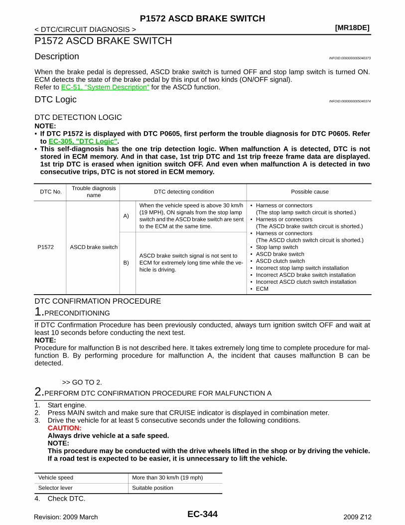
[MR18DE]P1572 ASCD BRAKE SWITCH
< DTC/CIRCUIT DIAGNOSIS >
P1572 ASCD BRAKE SWITCH
Description INFOID:0000000005040373
When the brake pedal is depressed, ASCD brake switch is turned OFF and stop lamp switch is turned ON.ECM detects the state of the brake pedal by this input of two kinds (ON/OFF signal).Refer to EC-51, "System Description" for the ASCD function.
DTC Logic INFOID:0000000005040374
DTC DETECTION LOGICNOTE:• If DTC P1572 is displayed with DTC P0605, first perform the trouble diagnosis for DTC P0605. Refer
to EC-305, "DTC Logic".• This self-diagnosis has the one trip detection logic. When malfunction A is detected, DTC is not
stored in ECM memory. And in that case, 1st trip DTC and 1st trip freeze frame data are displayed.1st trip DTC is erased when ignition switch OFF. And even when malfunction A is detected in twoconsecutive trips, DTC is not stored in ECM memory.
DTC CONFIRMATION PROCEDURE
1.PRECONDITIONING
If DTC Confirmation Procedure has been previously conducted, always turn ignition switch OFF and wait atleast 10 seconds before conducting the next test.NOTE:Procedure for malfunction B is not described here. It takes extremely long time to complete procedure for mal-function B. By performing procedure for malfunction A, the incident that causes malfunction B can bedetected.
>> GO TO 2.
2.PERFORM DTC CONFIRMATION PROCEDURE FOR MALFUNCTION A
1. Start engine.2. Press MAIN switch and make sure that CRUISE indicator is displayed in combination meter.3. Drive the vehicle for at least 5 consecutive seconds under the following conditions.
CAUTION:Always drive vehicle at a safe speed.NOTE:This procedure may be conducted with the drive wheels lifted in the shop or by driving the vehicle.If a road test is expected to be easier, it is unnecessary to lift the vehicle.
4. Check DTC.
DTC No.Trouble diagnosis
nameDTC detecting condition Possible cause
P1572 ASCD brake switch
A)
When the vehicle speed is above 30 km/h (19 MPH), ON signals from the stop lamp switch and the ASCD brake switch are sent to the ECM at the same time.
• Harness or connectors(The stop lamp switch circuit is shorted.)
• Harness or connectors(The ASCD brake switch circuit is shorted.)
• Harness or connectors(The ASCD clutch switch circuit is shorted.)
• Stop lamp switch• ASCD brake switch• ASCD clutch switch• Incorrect stop lamp switch installation• Incorrect ASCD brake switch installation• Incorrect ASCD clutch switch installation• ECM
B)ASCD brake switch signal is not sent to ECM for extremely long time while the ve-hicle is driving.
Vehicle speed More than 30 km/h (19 mph)
Selector lever Suitable position
EC-344Revision: 2009 March 2009 Z12
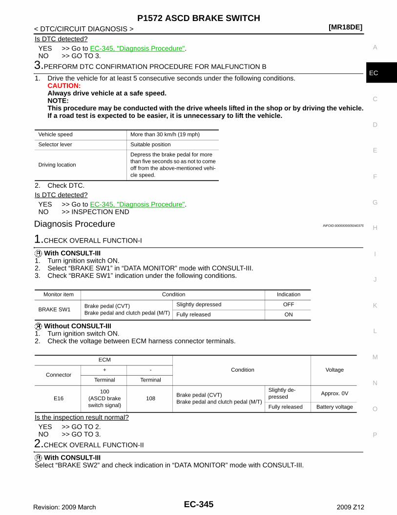
P1572 ASCD BRAKE SWITCH[MR18DE]
C
D
E
F
G
H
I
J
K
L
M
A
C
N
P
O
< DTC/CIRCUIT DIAGNOSIS >
E
Is DTC detected?YES >> Go to EC-345, "Diagnosis Procedure".NO >> GO TO 3.
3.PERFORM DTC CONFIRMATION PROCEDURE FOR MALFUNCTION B
1. Drive the vehicle for at least 5 consecutive seconds under the following conditions.CAUTION:Always drive vehicle at a safe speed.NOTE:This procedure may be conducted with the drive wheels lifted in the shop or by driving the vehicle.If a road test is expected to be easier, it is unnecessary to lift the vehicle.
2. Check DTC.Is DTC detected?YES >> Go to EC-345, "Diagnosis Procedure".NO >> INSPECTION END
Diagnosis Procedure INFOID:0000000005040375
1.CHECK OVERALL FUNCTION-I
With CONSULT-III1. Turn ignition switch ON.2. Select “BRAKE SW1” in “DATA MONITOR” mode with CONSULT-III.3. Check “BRAKE SW1” indication under the following conditions.
Without CONSULT-III1. Turn ignition switch ON.2. Check the voltage between ECM harness connector terminals.
Is the inspection result normal?YES >> GO TO 2.NO >> GO TO 3.
2.CHECK OVERALL FUNCTION-II
With CONSULT-IIISelect “BRAKE SW2” and check indication in “DATA MONITOR” mode with CONSULT-III.
Vehicle speed More than 30 km/h (19 mph)
Selector lever Suitable position
Driving location
Depress the brake pedal for more than five seconds so as not to come off from the above-mentioned vehi-cle speed.
Monitor item Condition Indication
BRAKE SW1Brake pedal (CVT)Brake pedal and clutch pedal (M/T)
Slightly depressed OFF
Fully released ON
ECM
Condition VoltageConnector
+ -
Terminal Terminal
E16100
(ASCD brake switch signal)
108Brake pedal (CVT)Brake pedal and clutch pedal (M/T)
Slightly de-pressed
Approx. 0V
Fully released Battery voltage
EC-345Revision: 2009 March 2009 Z12
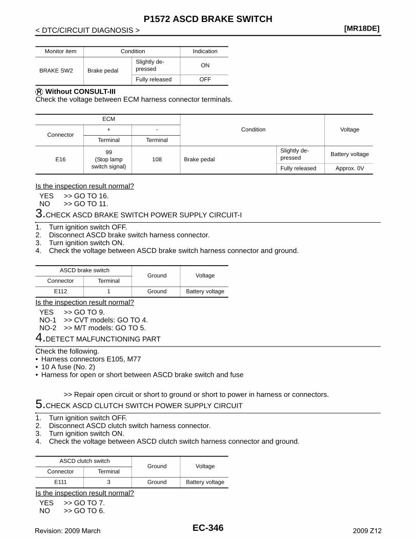
[MR18DE]P1572 ASCD BRAKE SWITCH
< DTC/CIRCUIT DIAGNOSIS >
Without CONSULT-IIICheck the voltage between ECM harness connector terminals.
Is the inspection result normal?YES >> GO TO 16.NO >> GO TO 11.
3.CHECK ASCD BRAKE SWITCH POWER SUPPLY CIRCUIT-I
1. Turn ignition switch OFF.2. Disconnect ASCD brake switch harness connector.3. Turn ignition switch ON.4. Check the voltage between ASCD brake switch harness connector and ground.
Is the inspection result normal?YES >> GO TO 9.NO-1 >> CVT models: GO TO 4.NO-2 >> M/T models: GO TO 5.
4.DETECT MALFUNCTIONING PART
Check the following.• Harness connectors E105, M77• 10 A fuse (No. 2)• Harness for open or short between ASCD brake switch and fuse
>> Repair open circuit or short to ground or short to power in harness or connectors.
5.CHECK ASCD CLUTCH SWITCH POWER SUPPLY CIRCUIT
1. Turn ignition switch OFF.2. Disconnect ASCD clutch switch harness connector.3. Turn ignition switch ON.4. Check the voltage between ASCD clutch switch harness connector and ground.
Is the inspection result normal?YES >> GO TO 7.NO >> GO TO 6.
Monitor item Condition Indication
BRAKE SW2 Brake pedal
Slightly de-pressed
ON
Fully released OFF
ECM
Condition VoltageConnector
+ -
Terminal Terminal
E1699
(Stop lamp switch signal)
108 Brake pedal
Slightly de-pressed
Battery voltage
Fully released Approx. 0V
ASCD brake switchGround Voltage
Connector Terminal
E112 1 Ground Battery voltage
ASCD clutch switchGround Voltage
Connector Terminal
E111 3 Ground Battery voltage
EC-346Revision: 2009 March 2009 Z12
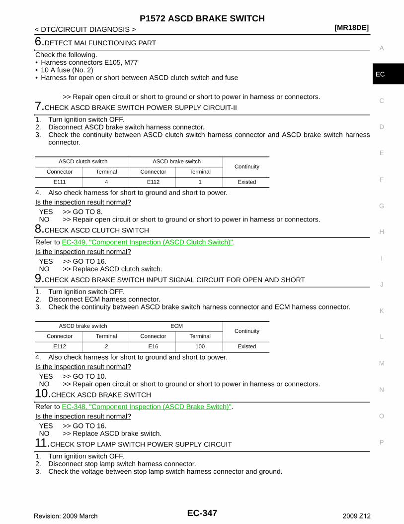
P1572 ASCD BRAKE SWITCH[MR18DE]
C
D
E
F
G
H
I
J
K
L
M
A
C
N
P
O
< DTC/CIRCUIT DIAGNOSIS >
E
6.DETECT MALFUNCTIONING PART
Check the following.• Harness connectors E105, M77• 10 A fuse (No. 2)• Harness for open or short between ASCD clutch switch and fuse
>> Repair open circuit or short to ground or short to power in harness or connectors.
7.CHECK ASCD BRAKE SWITCH POWER SUPPLY CIRCUIT-II
1. Turn ignition switch OFF.2. Disconnect ASCD brake switch harness connector.3. Check the continuity between ASCD clutch switch harness connector and ASCD brake switch harness
connector.
4. Also check harness for short to ground and short to power.Is the inspection result normal?YES >> GO TO 8.NO >> Repair open circuit or short to ground or short to power in harness or connectors.
8.CHECK ASCD CLUTCH SWITCH
Refer to EC-349, "Component Inspection (ASCD Clutch Switch)".Is the inspection result normal?YES >> GO TO 16.NO >> Replace ASCD clutch switch.
9.CHECK ASCD BRAKE SWITCH INPUT SIGNAL CIRCUIT FOR OPEN AND SHORT
1. Turn ignition switch OFF.2. Disconnect ECM harness connector.3. Check the continuity between ASCD brake switch harness connector and ECM harness connector.
4. Also check harness for short to ground and short to power.Is the inspection result normal?YES >> GO TO 10.NO >> Repair open circuit or short to ground or short to power in harness or connectors.
10.CHECK ASCD BRAKE SWITCH
Refer to EC-348, "Component Inspection (ASCD Brake Switch)".Is the inspection result normal?YES >> GO TO 16.NO >> Replace ASCD brake switch.
11.CHECK STOP LAMP SWITCH POWER SUPPLY CIRCUIT
1. Turn ignition switch OFF.2. Disconnect stop lamp switch harness connector.3. Check the voltage between stop lamp switch harness connector and ground.
ASCD clutch switch ASCD brake switchContinuity
Connector Terminal Connector Terminal
E111 4 E112 1 Existed
ASCD brake switch ECMContinuity
Connector Terminal Connector Terminal
E112 2 E16 100 Existed
EC-347Revision: 2009 March 2009 Z12
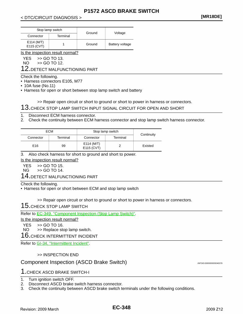
[MR18DE]P1572 ASCD BRAKE SWITCH
< DTC/CIRCUIT DIAGNOSIS >
Is the inspection result normal?YES >> GO TO 13.NO >> GO TO 12.
12.DETECT MALFUNCTIONING PART
Check the following.• Harness connectors E105, M77• 10A fuse (No.11)• Harness for open or short between stop lamp switch and battery
>> Repair open circuit or short to ground or short to power in harness or connectors.
13.CHECK STOP LAMP SWITCH INPUT SIGNAL CIRCUIT FOR OPEN AND SHORT
1. Disconnect ECM harness connector.2. Check the continuity between ECM harness connector and stop lamp switch harness connector.
3. Also check harness for short to ground and short to power.Is the inspection result normal?YES >> GO TO 15.NG >> GO TO 14.
14.DETECT MALFUNCTIONING PART
Check the following.• Harness for open or short between ECM and stop lamp switch
>> Repair open circuit or short to ground or short to power in harness or connectors.
15.CHECK STOP LAMP SWITCH
Refer to EC-349, "Component Inspection (Stop Lamp Switch)".Is the inspection result normal?YES >> GO TO 16.NO >> Replace stop lamp switch.
16.CHECK INTERMITTENT INCIDENT
Refer to GI-34, "Intermittent Incident".
>> INSPECTION END
Component Inspection (ASCD Brake Switch) INFOID:0000000005040376
1.CHECK ASCD BRAKE SWITCH-I
1. Turn ignition switch OFF.2. Disconnect ASCD brake switch harness connector.3. Check the continuity between ASCD brake switch terminals under the following conditions.
Stop lamp switchGround Voltage
Connector Terminal
E114 (M/T)E115 (CVT)
1 Ground Battery voltage
ECM Stop lamp switchContinuity
Connector Terminal Connector Terminal
E16 99E114 (M/T)E115 (CVT)
2 Existed
EC-348Revision: 2009 March 2009 Z12
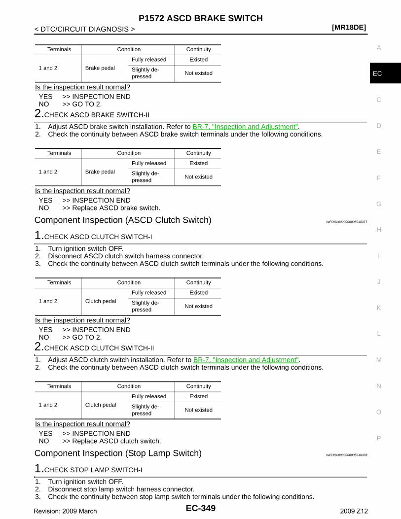
P1572 ASCD BRAKE SWITCH[MR18DE]
C
D
E
F
G
H
I
J
K
L
M
A
C
N
P
O
< DTC/CIRCUIT DIAGNOSIS >
E
Is the inspection result normal?YES >> INSPECTION ENDNO >> GO TO 2.
2.CHECK ASCD BRAKE SWITCH-II
1. Adjust ASCD brake switch installation. Refer to BR-7, "Inspection and Adjustment".2. Check the continuity between ASCD brake switch terminals under the following conditions.
Is the inspection result normal?YES >> INSPECTION ENDNO >> Replace ASCD brake switch.
Component Inspection (ASCD Clutch Switch) INFOID:0000000005040377
1.CHECK ASCD CLUTCH SWITCH-I
1. Turn ignition switch OFF.2. Disconnect ASCD clutch switch harness connector.3. Check the continuity between ASCD clutch switch terminals under the following conditions.
Is the inspection result normal?YES >> INSPECTION ENDNO >> GO TO 2.
2.CHECK ASCD CLUTCH SWITCH-II
1. Adjust ASCD clutch switch installation. Refer to BR-7, "Inspection and Adjustment".2. Check the continuity between ASCD clutch switch terminals under the following conditions.
Is the inspection result normal?YES >> INSPECTION ENDNO >> Replace ASCD clutch switch.
Component Inspection (Stop Lamp Switch) INFOID:0000000005040378
1.CHECK STOP LAMP SWITCH-I
1. Turn ignition switch OFF.2. Disconnect stop lamp switch harness connector.3. Check the continuity between stop lamp switch terminals under the following conditions.
Terminals Condition Continuity
1 and 2 Brake pedal
Fully released Existed
Slightly de-pressed
Not existed
Terminals Condition Continuity
1 and 2 Brake pedal
Fully released Existed
Slightly de-pressed
Not existed
Terminals Condition Continuity
1 and 2 Clutch pedal
Fully released Existed
Slightly de-pressed
Not existed
Terminals Condition Continuity
1 and 2 Clutch pedal
Fully released Existed
Slightly de-pressed
Not existed
EC-349Revision: 2009 March 2009 Z12
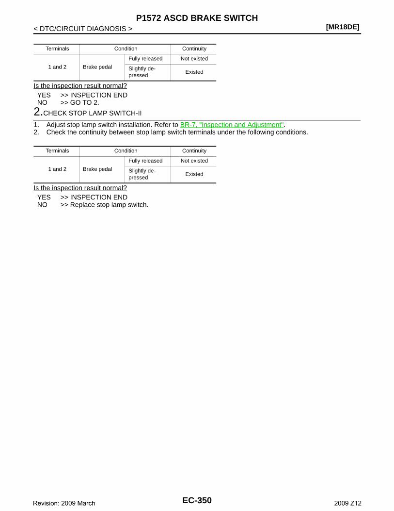
[MR18DE]P1572 ASCD BRAKE SWITCH
< DTC/CIRCUIT DIAGNOSIS >
Is the inspection result normal?YES >> INSPECTION ENDNO >> GO TO 2.
2.CHECK STOP LAMP SWITCH-II
1. Adjust stop lamp switch installation. Refer to BR-7, "Inspection and Adjustment".2. Check the continuity between stop lamp switch terminals under the following conditions.
Is the inspection result normal?YES >> INSPECTION ENDNO >> Replace stop lamp switch.
Terminals Condition Continuity
1 and 2 Brake pedal
Fully released Not existed
Slightly de-pressed
Existed
Terminals Condition Continuity
1 and 2 Brake pedal
Fully released Not existed
Slightly de-pressed
Existed
EC-350Revision: 2009 March 2009 Z12
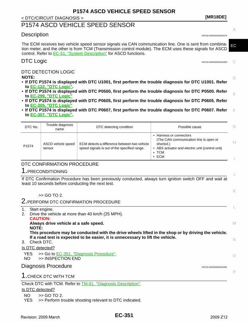
P1574 ASCD VEHICLE SPEED SENSOR[MR18DE]
C
D
E
F
G
H
I
J
K
L
M
A
C
N
P
O
< DTC/CIRCUIT DIAGNOSIS >
E
P1574 ASCD VEHICLE SPEED SENSOR
Description INFOID:0000000005040379
The ECM receives two vehicle speed sensor signals via CAN communication line. One is sent from combina-tion meter, and the other is from TCM (Transmission control module). The ECM uses these signals for ASCDcontrol. Refer to EC-51, "System Description" for ASCD functions.
DTC Logic INFOID:0000000005040380
DTC DETECTION LOGICNOTE:• If DTC P1574 is displayed with DTC U1001, first perform the trouble diagnosis for DTC U1001. Refer
to EC-122, "DTC Logic".• If DTC P1574 is displayed with DTC P0500, first perform the trouble diagnosis for DTC P0500. Refer
to EC-299, "DTC Logic"• If DTC P1574 is displayed with DTC P0605, first perform the trouble diagnosis for DTC P0605. Refer
to EC-305, "DTC Logic"• If DTC P1574 is displayed with DTC P0607, first perform the trouble diagnosis for DTC P0607. Refer
to EC-307, "DTC Logic".
DTC CONFIRMATION PROCEDURE
1.PRECONDITIONING
If DTC Confirmation Procedure has been previously conducted, always turn ignition switch OFF and wait atleast 10 seconds before conducting the next test.
>> GO TO 2.
2.PERFORM DTC CONFIRMATION PROCEDURE
1. Start engine.2. Drive the vehicle at more than 40 km/h (25 MPH).
CAUTION:Always drive vehicle at a safe speed.NOTE:This procedure may be conducted with the drive wheels lifted in the shop or by driving the vehicle.If a road test is expected to be easier, it is unnecessary to lift the vehicle.
3. Check DTC.Is DTC detected?YES >> Go to EC-351, "Diagnosis Procedure".NO >> INSPECTION END
Diagnosis Procedure INFOID:0000000005040381
1.CHECK DTC WITH TCM
Check DTC with TCM. Refer to TM-91, "Diagnosis Description".Is DTC detected?NO >> GO TO 2.YES >> Perform trouble shooting relevant to DTC indicated.
DTC No.Trouble diagnosis
nameDTC detecting condition Possible cause
P1574ASCD vehicle speed sensor
ECM detects a difference between two vehicle speed signals is out of the specified range.
• Harness or connectors(The CAN communication line is open or shorted.)
• ABS actuator and electric unit (control unit)• TCM• ECM
EC-351Revision: 2009 March 2009 Z12
[MR18DE]P1574 ASCD VEHICLE SPEED SENSOR
< DTC/CIRCUIT DIAGNOSIS >
2.CHECK DTC WITH “ABS ACTUATOR AND ELECTRIC UNIT (CONTROL UNIT)”
Refer to BRC-22, "CONSULT-III Function".Is DTC detected?NO >> INSPECTION ENDYES >> Perform trouble shooting relevant to DTC indicated.
EC-352Revision: 2009 March 2009 Z12
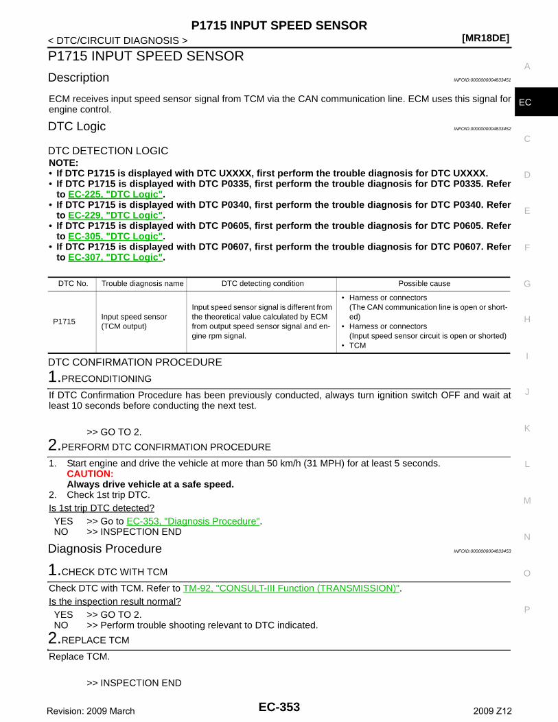
P1715 INPUT SPEED SENSOR[MR18DE]
C
D
E
F
G
H
I
J
K
L
M
A
C
N
P
O
< DTC/CIRCUIT DIAGNOSIS >
E
P1715 INPUT SPEED SENSOR
Description INFOID:0000000004833451
ECM receives input speed sensor signal from TCM via the CAN communication line. ECM uses this signal forengine control.
DTC Logic INFOID:0000000004833452
DTC DETECTION LOGICNOTE:• If DTC P1715 is displayed with DTC UXXXX, first perform the trouble diagnosis for DTC UXXXX.• If DTC P1715 is displayed with DTC P0335, first perform the trouble diagnosis for DTC P0335. Refer
to EC-225, "DTC Logic".• If DTC P1715 is displayed with DTC P0340, first perform the trouble diagnosis for DTC P0340. Refer
to EC-229, "DTC Logic".• If DTC P1715 is displayed with DTC P0605, first perform the trouble diagnosis for DTC P0605. Refer
to EC-305, "DTC Logic".• If DTC P1715 is displayed with DTC P0607, first perform the trouble diagnosis for DTC P0607. Refer
to EC-307, "DTC Logic".
DTC CONFIRMATION PROCEDURE
1.PRECONDITIONING
If DTC Confirmation Procedure has been previously conducted, always turn ignition switch OFF and wait atleast 10 seconds before conducting the next test.
>> GO TO 2.
2.PERFORM DTC CONFIRMATION PROCEDURE
1. Start engine and drive the vehicle at more than 50 km/h (31 MPH) for at least 5 seconds.CAUTION:Always drive vehicle at a safe speed.
2. Check 1st trip DTC.Is 1st trip DTC detected?YES >> Go to EC-353, "Diagnosis Procedure".NO >> INSPECTION END
Diagnosis Procedure INFOID:0000000004833453
1.CHECK DTC WITH TCM
Check DTC with TCM. Refer to TM-92, "CONSULT-III Function (TRANSMISSION)".Is the inspection result normal?YES >> GO TO 2.NO >> Perform trouble shooting relevant to DTC indicated.
2.REPLACE TCM
Replace TCM.
>> INSPECTION END
DTC No. Trouble diagnosis name DTC detecting condition Possible cause
P1715Input speed sensor(TCM output)
Input speed sensor signal is different from the theoretical value calculated by ECM from output speed sensor signal and en-gine rpm signal.
• Harness or connectors(The CAN communication line is open or short-ed)
• Harness or connectors(Input speed sensor circuit is open or shorted)
• TCM
EC-353Revision: 2009 March 2009 Z12
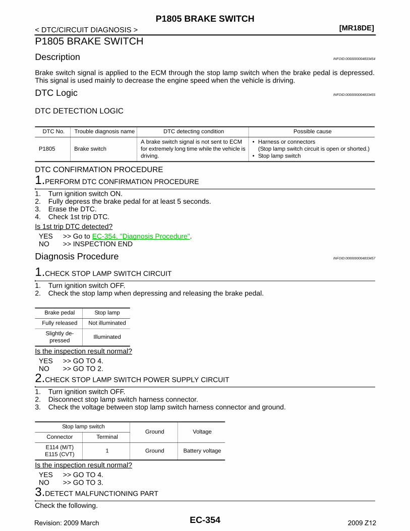
[MR18DE]P1805 BRAKE SWITCH
< DTC/CIRCUIT DIAGNOSIS >
P1805 BRAKE SWITCH
Description INFOID:0000000004833454
Brake switch signal is applied to the ECM through the stop lamp switch when the brake pedal is depressed.This signal is used mainly to decrease the engine speed when the vehicle is driving.
DTC Logic INFOID:0000000004833455
DTC DETECTION LOGIC
DTC CONFIRMATION PROCEDURE
1.PERFORM DTC CONFIRMATION PROCEDURE
1. Turn ignition switch ON.2. Fully depress the brake pedal for at least 5 seconds.3. Erase the DTC.4. Check 1st trip DTC.Is 1st trip DTC detected?YES >> Go to EC-354, "Diagnosis Procedure".NO >> INSPECTION END
Diagnosis Procedure INFOID:0000000004833457
1.CHECK STOP LAMP SWITCH CIRCUIT
1. Turn ignition switch OFF.2. Check the stop lamp when depressing and releasing the brake pedal.
Is the inspection result normal?YES >> GO TO 4.NO >> GO TO 2.
2.CHECK STOP LAMP SWITCH POWER SUPPLY CIRCUIT
1. Turn ignition switch OFF.2. Disconnect stop lamp switch harness connector.3. Check the voltage between stop lamp switch harness connector and ground.
Is the inspection result normal?YES >> GO TO 4.NO >> GO TO 3.
3.DETECT MALFUNCTIONING PART
Check the following.
DTC No. Trouble diagnosis name DTC detecting condition Possible cause
P1805 Brake switchA brake switch signal is not sent to ECM for extremely long time while the vehicle is driving.
• Harness or connectors(Stop lamp switch circuit is open or shorted.)
• Stop lamp switch
Brake pedal Stop lamp
Fully released Not illuminated
Slightly de-pressed
Illuminated
Stop lamp switchGround Voltage
Connector Terminal
E114 (M/T)E115 (CVT)
1 Ground Battery voltage
EC-354Revision: 2009 March 2009 Z12
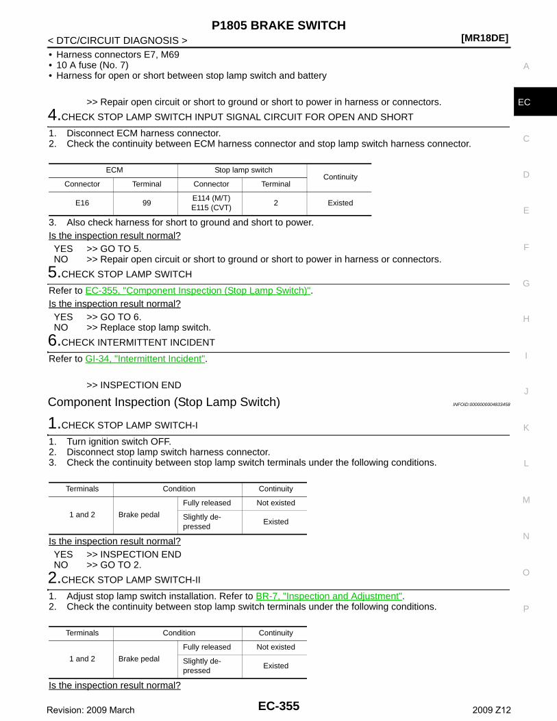
P1805 BRAKE SWITCH[MR18DE]
C
D
E
F
G
H
I
J
K
L
M
A
C
N
P
O
< DTC/CIRCUIT DIAGNOSIS >
E
• Harness connectors E7, M69• 10 A fuse (No. 7)• Harness for open or short between stop lamp switch and battery
>> Repair open circuit or short to ground or short to power in harness or connectors.
4.CHECK STOP LAMP SWITCH INPUT SIGNAL CIRCUIT FOR OPEN AND SHORT
1. Disconnect ECM harness connector.2. Check the continuity between ECM harness connector and stop lamp switch harness connector.
3. Also check harness for short to ground and short to power.Is the inspection result normal?YES >> GO TO 5.NO >> Repair open circuit or short to ground or short to power in harness or connectors.
5.CHECK STOP LAMP SWITCH
Refer to EC-355, "Component Inspection (Stop Lamp Switch)".Is the inspection result normal?YES >> GO TO 6.NO >> Replace stop lamp switch.
6.CHECK INTERMITTENT INCIDENT
Refer to GI-34, "Intermittent Incident".
>> INSPECTION END
Component Inspection (Stop Lamp Switch) INFOID:0000000004833458
1.CHECK STOP LAMP SWITCH-I
1. Turn ignition switch OFF.2. Disconnect stop lamp switch harness connector.3. Check the continuity between stop lamp switch terminals under the following conditions.
Is the inspection result normal?YES >> INSPECTION ENDNO >> GO TO 2.
2.CHECK STOP LAMP SWITCH-II
1. Adjust stop lamp switch installation. Refer to BR-7, "Inspection and Adjustment".2. Check the continuity between stop lamp switch terminals under the following conditions.
Is the inspection result normal?
ECM Stop lamp switchContinuity
Connector Terminal Connector Terminal
E16 99E114 (M/T)E115 (CVT)
2 Existed
Terminals Condition Continuity
1 and 2 Brake pedal
Fully released Not existed
Slightly de-pressed
Existed
Terminals Condition Continuity
1 and 2 Brake pedal
Fully released Not existed
Slightly de-pressed
Existed
EC-355Revision: 2009 March 2009 Z12
[MR18DE]P1805 BRAKE SWITCH
< DTC/CIRCUIT DIAGNOSIS >YES >> INSPECTION ENDNO >> Replace stop lamp switch.
EC-356Revision: 2009 March 2009 Z12
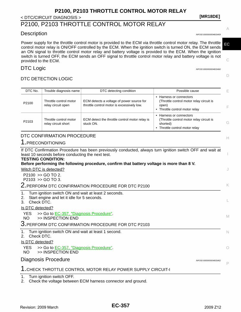
P2100, P2103 THROTTLE CONTROL MOTOR RELAY[MR18DE]
C
D
E
F
G
H
I
J
K
L
M
A
C
N
P
O
< DTC/CIRCUIT DIAGNOSIS >
E
P2100, P2103 THROTTLE CONTROL MOTOR RELAY
Description INFOID:0000000004833459
Power supply for the throttle control motor is provided to the ECM via throttle control motor relay. The throttlecontrol motor relay is ON/OFF controlled by the ECM. When the ignition switch is turned ON, the ECM sendsan ON signal to throttle control motor relay and battery voltage is provided to the ECM. When the ignitionswitch is turned OFF, the ECM sends an OFF signal to throttle control motor relay and battery voltage is notprovided to the ECM.
DTC Logic INFOID:0000000004833460
DTC DETECTION LOGIC
DTC CONFIRMATION PROCEDURE
1.PRECONDITIONING
If DTC Confirmation Procedure has been previously conducted, always turn ignition switch OFF and wait atleast 10 seconds before conducting the next test.TESTING CONDITION:Before performing the following procedure, confirm that battery voltage is more than 8 V.Witch DTC is detected?P2100 >> GO TO 2.P2103 >> GO TO 3.
2.PERFORM DTC CONFIRMATION PROCEDURE FOR DTC P2100
1. Turn ignition switch ON and wait at least 2 seconds.2. Start engine and let it idle for 5 seconds.3. Check DTC.Is DTC detected?YES >> Go to EC-357, "Diagnosis Procedure".NO >> INSPECTION END
3.PERFORM DTC CONFIRMATION PROCEDURE FOR DTC P2103
1. Turn ignition switch ON and wait at least 1 second.2. Check DTC.Is DTC detected?YES >> Go to EC-357, "Diagnosis Procedure".NO >> INSPECTION END
Diagnosis Procedure INFOID:0000000004833462
1.CHECK THROTTLE CONTROL MOTOR RELAY POWER SUPPLY CIRCUIT-I
1. Turn ignition switch OFF.2. Check the voltage between ECM harness connector and ground.
DTC No. Trouble diagnosis name DTC detecting condition Possible cause
P2100Throttle control motor relay circuit open
ECM detects a voltage of power source for throttle control motor is excessively low.
• Harness or connectors(Throttle control motor relay circuit is open)
• Throttle control motor relay
P2103Throttle control motor relay circuit short
ECM detect the throttle control motor relay is stuck ON.
• Harness or connectors(Throttle control motor relay circuit is shorted)
• Throttle control motor relay
EC-357Revision: 2009 March 2009 Z12
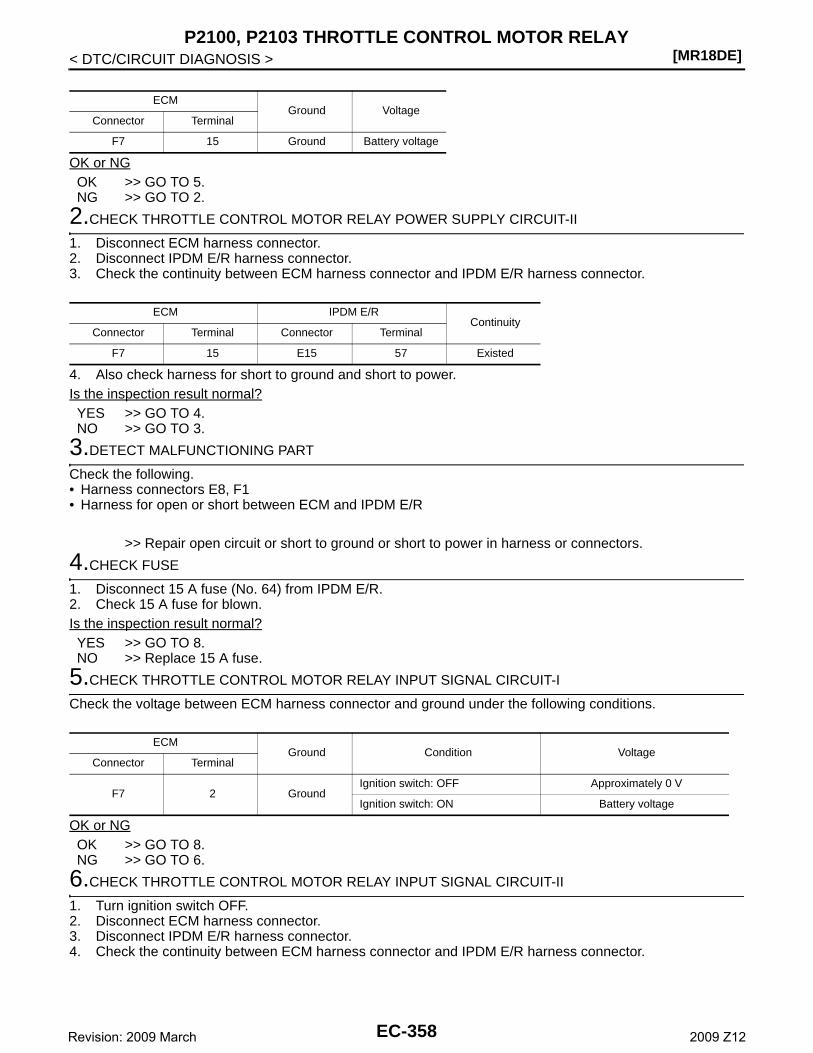
[MR18DE]P2100, P2103 THROTTLE CONTROL MOTOR RELAY
< DTC/CIRCUIT DIAGNOSIS >
OK or NGOK >> GO TO 5.NG >> GO TO 2.
2.CHECK THROTTLE CONTROL MOTOR RELAY POWER SUPPLY CIRCUIT-II
1. Disconnect ECM harness connector.2. Disconnect IPDM E/R harness connector.3. Check the continuity between ECM harness connector and IPDM E/R harness connector.
4. Also check harness for short to ground and short to power.Is the inspection result normal?YES >> GO TO 4.NO >> GO TO 3.
3.DETECT MALFUNCTIONING PART
Check the following.• Harness connectors E8, F1• Harness for open or short between ECM and IPDM E/R
>> Repair open circuit or short to ground or short to power in harness or connectors.
4.CHECK FUSE
1. Disconnect 15 A fuse (No. 64) from IPDM E/R.2. Check 15 A fuse for blown.Is the inspection result normal?YES >> GO TO 8.NO >> Replace 15 A fuse.
5.CHECK THROTTLE CONTROL MOTOR RELAY INPUT SIGNAL CIRCUIT-I
Check the voltage between ECM harness connector and ground under the following conditions.
OK or NGOK >> GO TO 8.NG >> GO TO 6.
6.CHECK THROTTLE CONTROL MOTOR RELAY INPUT SIGNAL CIRCUIT-II
1. Turn ignition switch OFF.2. Disconnect ECM harness connector.3. Disconnect IPDM E/R harness connector.4. Check the continuity between ECM harness connector and IPDM E/R harness connector.
ECMGround Voltage
Connector Terminal
F7 15 Ground Battery voltage
ECM IPDM E/RContinuity
Connector Terminal Connector Terminal
F7 15 E15 57 Existed
ECMGround Condition Voltage
Connector Terminal
F7 2 GroundIgnition switch: OFF Approximately 0 V
Ignition switch: ON Battery voltage
EC-358Revision: 2009 March 2009 Z12
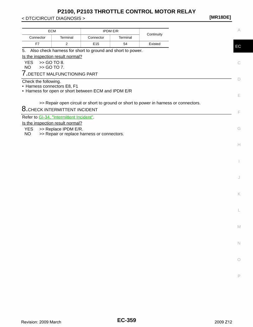
P2100, P2103 THROTTLE CONTROL MOTOR RELAY[MR18DE]
C
D
E
F
G
H
I
J
K
L
M
A
C
N
P
O
< DTC/CIRCUIT DIAGNOSIS >
E5. Also check harness for short to ground and short to power.Is the inspection result normal?YES >> GO TO 8.NO >> GO TO 7.
7.DETECT MALFUNCTIONING PART
Check the following.• Harness connectors E8, F1• Harness for open or short between ECM and IPDM E/R
>> Repair open circuit or short to ground or short to power in harness or connectors.
8.CHECK INTERMITTENT INCIDENT
Refer to GI-34, "Intermittent Incident".Is the inspection result normal?YES >> Replace IPDM E/R.NO >> Repair or replace harness or connectors.
ECM IPDM E/RContinuity
Connector Terminal Connector Terminal
F7 2 E15 54 Existed
EC-359Revision: 2009 March 2009 Z12
[MR18DE]P2101 ELECTRIC THROTTLE CONTROL FUNCTION
< DTC/CIRCUIT DIAGNOSIS >
P2101 ELECTRIC THROTTLE CONTROL FUNCTION
Description INFOID:0000000004833463
Electric throttle control actuator consists of throttle control motor, throttle position sensor, etc.The throttle control motor is operated by the ECM and it opens and closes the throttle valve.The current opening angle of the throttle valve is detected by the throttle position sensor and it provides feed-back to the ECM. ECM controls the throttle valve opening angle in response to driving condition via the throttlecontrol motor.
DTC Logic INFOID:0000000004833464
DTC DETECTION LOGICNOTE:• If DTC P2101 is displayed with DTC P2100, first perform the trouble diagnosis for DTC P2100. Refer
to EC-357, "DTC Logic".• If DTC P2101 is displayed with DTC P2119, first perform the trouble diagnosis for DTC P2119. Refer
to EC-366, "DTC Logic".
DTC CONFIRMATION PROCEDURE
1.PRECONDITIONING
If DTC Confirmation Procedure has been previously conducted, always turn ignition switch OFF and wait atleast 10 seconds before conducting the next test.TESTING CONDITION:Before performing the following procedure, confirm that battery voltage is more than 11 V whenengine is running.
>> GO TO 2.
2.PERFORM DTC CONFIRMATION PROCEDURE
1. Turn ignition switch ON and wait at least 2 seconds.2. Start engine and let it idle for 5 seconds.3. Check DTC.Is DTC detected?YES >> Go to EC-360, "Diagnosis Procedure".NO >> INSPECTION END
Diagnosis Procedure INFOID:0000000004833466
1.CHECK GROUND CONNECTION
1. Turn ignition switch OFF.2. Check ground connection E38. Refer to GI-37, "Circuit Inspection". Is the inspection result normal?YES >> GO TO 2.NO >> Repair or replace ground connection.
2.CHECK THROTTLE CONTROL MOTOR RELAY INPUT SIGNAL CIRCUIT-I
1. Check the voltage between ECM harness connector and ground under the following conditions.
DTC No. Trouble diagnosis name DTC detecting condition Possible cause
P2101Electric throttle control performance
Electric throttle control function does not operate properly.
• Harness or connectors(Throttle control motor circuit is open or shorted)
• Electric throttle control actuator
EC-360Revision: 2009 March 2009 Z12
P2101 ELECTRIC THROTTLE CONTROL FUNCTION[MR18DE]
C
D
E
F
G
H
I
J
K
L
M
A
C
N
P
O
< DTC/CIRCUIT DIAGNOSIS >
E
Is the inspection result normal?YES >> GO TO 9.NO >> GO TO 3.
3.CHECK THROTTLE CONTROL MOTOR RELAY POWER SUPPLY CIRCUIT
1. Turn ignition switch OFF.2. Disconnect ECM harness connector.3. Disconnect IPDM E/R harness connector.4. Check the continuity between ECM harness connector and IPDM E/R harness connector.
5. Also check harness for short to ground and short to power.Is the inspection result normal?YES >> GO TO 5.NO >> GO TO 4.
4.DETECT MALFUNCTIONING PART
Check the following.• Harness connectors E8, F8• Harness for open or short between ECM and IPDM E/R
>> Repair open circuit or short to ground or short to power in harness or connectors.
5.CHECK THROTTLE CONTROL MOTOR RELAY INPUT SIGNAL CIRCUIT-II
1. Check the continuity between ECM harness connector and IPDM E/R harness connector.
2. Also check harness for short to ground and short to power.Is the inspection result normal?YES >> GO TO 7.NO >> GO TO 6.
6.DETECT MALFUNCTIONING PART
Check the following.• Harness connectors E8, F1• Harness for open or short between ECM and IPDM E/R
>> Repair open circuit or short to ground or short to power in harness or connectors.
7.CHECK FUSE
1. Disconnect 15 A fuse (No. 64) from IPDM E/R.2. Check 15 A fuse for blown.Is the inspection result normal?
ECMGround Condition Voltage
Connector Terminal
F7 2 Ground
Ignition switch: OFF
Approx. 0 V
Ignition switch: ON
Battery voltage
IPDM E/R ECMContinuity
Connector Terminal Connector Terminal
E15 57 F7 15 Existed
IPDM E/R ECMContinuity
Connector Terminal Connector Terminal
E15 54 F7 2 Existed
EC-361Revision: 2009 March 2009 Z12
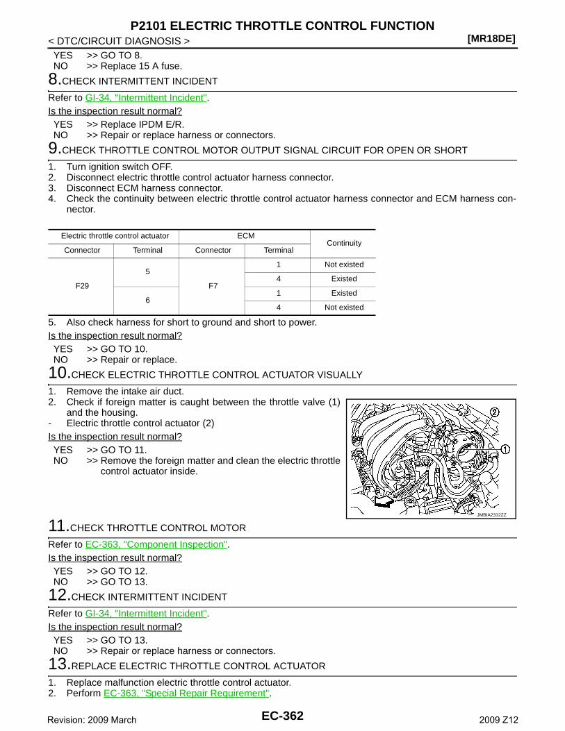
[MR18DE]P2101 ELECTRIC THROTTLE CONTROL FUNCTION
< DTC/CIRCUIT DIAGNOSIS >YES >> GO TO 8.NO >> Replace 15 A fuse.
8.CHECK INTERMITTENT INCIDENT
Refer to GI-34, "Intermittent Incident".Is the inspection result normal?YES >> Replace IPDM E/R.NO >> Repair or replace harness or connectors.
9.CHECK THROTTLE CONTROL MOTOR OUTPUT SIGNAL CIRCUIT FOR OPEN OR SHORT
1. Turn ignition switch OFF.2. Disconnect electric throttle control actuator harness connector.3. Disconnect ECM harness connector.4. Check the continuity between electric throttle control actuator harness connector and ECM harness con-
nector.
5. Also check harness for short to ground and short to power.Is the inspection result normal?YES >> GO TO 10.NO >> Repair or replace.
10.CHECK ELECTRIC THROTTLE CONTROL ACTUATOR VISUALLY
1. Remove the intake air duct.2. Check if foreign matter is caught between the throttle valve (1)
and the housing.- Electric throttle control actuator (2)Is the inspection result normal?YES >> GO TO 11.NO >> Remove the foreign matter and clean the electric throttle
control actuator inside.
11.CHECK THROTTLE CONTROL MOTOR
Refer to EC-363, "Component Inspection".Is the inspection result normal?YES >> GO TO 12.NO >> GO TO 13.
12.CHECK INTERMITTENT INCIDENT
Refer to GI-34, "Intermittent Incident".Is the inspection result normal?YES >> GO TO 13.NO >> Repair or replace harness or connectors.
13.REPLACE ELECTRIC THROTTLE CONTROL ACTUATOR
1. Replace malfunction electric throttle control actuator.2. Perform EC-363, "Special Repair Requirement".
Electric throttle control actuator ECMContinuity
Connector Terminal Connector Terminal
F29
5
F7
1 Not existed
4 Existed
61 Existed
4 Not existed
JMBIA2312ZZ
EC-362Revision: 2009 March 2009 Z12
P2101 ELECTRIC THROTTLE CONTROL FUNCTION[MR18DE]
C
D
E
F
G
H
I
J
K
L
M
A
C
N
P
O
< DTC/CIRCUIT DIAGNOSIS >
E
>> INSPECTION END
Component Inspection INFOID:0000000004833467
1.CHECK THROTTLE CONTROL MOTOR
1. Turn ignition switch OFF.2. Disconnect electric throttle control actuator harness connector.3. Check the resistance between electric throttle control actuator terminals as per the following.
Is the inspection result normal?YES >> INSPECTION ENDNO >> GO TO 2.
2.REPLACE ELECTRIC THROTTLE CONTROL ACTUATOR
1. Replace electric throttle control actuator.2. Perform EC-363, "Special Repair Requirement".
>> INSPECTION END
Special Repair Requirement INFOID:0000000004833468
1.PERFORM THROTTLE VALVE CLOSED POSITION LEARNING
Refer to EC-17, "THROTTLE VALVE CLOSED POSITION LEARNING : Special Repair Requirement"
>> GO TO 2.
2.PERFORM IDLE AIR VOLUME LEARNING
Refer to EC-17, "IDLE AIR VOLUME LEARNING : Special Repair Requirement"
>> END
Terminals Resistance
5 and 6 Approx. 1 - 15 Ω [at 25°C (77°F)]
EC-363Revision: 2009 March 2009 Z12
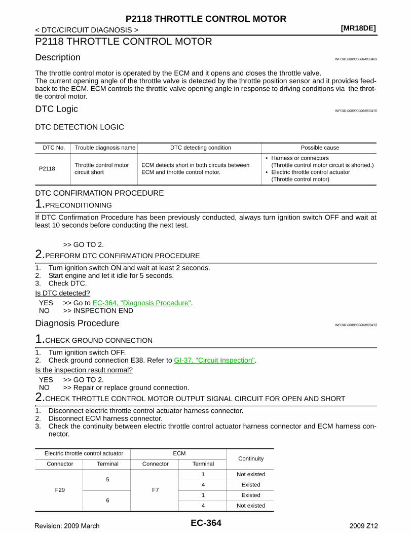
[MR18DE]P2118 THROTTLE CONTROL MOTOR
< DTC/CIRCUIT DIAGNOSIS >
P2118 THROTTLE CONTROL MOTOR
Description INFOID:0000000004833469
The throttle control motor is operated by the ECM and it opens and closes the throttle valve.The current opening angle of the throttle valve is detected by the throttle position sensor and it provides feed-back to the ECM. ECM controls the throttle valve opening angle in response to driving conditions via the throt-tle control motor.
DTC Logic INFOID:0000000004833470
DTC DETECTION LOGIC
DTC CONFIRMATION PROCEDURE
1.PRECONDITIONING
If DTC Confirmation Procedure has been previously conducted, always turn ignition switch OFF and wait atleast 10 seconds before conducting the next test.
>> GO TO 2.
2.PERFORM DTC CONFIRMATION PROCEDURE
1. Turn ignition switch ON and wait at least 2 seconds.2. Start engine and let it idle for 5 seconds.3. Check DTC.Is DTC detected?YES >> Go to EC-364, "Diagnosis Procedure".NO >> INSPECTION END
Diagnosis Procedure INFOID:0000000004833472
1.CHECK GROUND CONNECTION
1. Turn ignition switch OFF.2. Check ground connection E38. Refer to GI-37, "Circuit Inspection". Is the inspection result normal?YES >> GO TO 2.NO >> Repair or replace ground connection.
2.CHECK THROTTLE CONTROL MOTOR OUTPUT SIGNAL CIRCUIT FOR OPEN AND SHORT
1. Disconnect electric throttle control actuator harness connector.2. Disconnect ECM harness connector.3. Check the continuity between electric throttle control actuator harness connector and ECM harness con-
nector.
DTC No. Trouble diagnosis name DTC detecting condition Possible cause
P2118Throttle control motor circuit short
ECM detects short in both circuits between ECM and throttle control motor.
• Harness or connectors(Throttle control motor circuit is shorted.)
• Electric throttle control actuator(Throttle control motor)
Electric throttle control actuator ECMContinuity
Connector Terminal Connector Terminal
F29
5
F7
1 Not existed
4 Existed
61 Existed
4 Not existed
EC-364Revision: 2009 March 2009 Z12
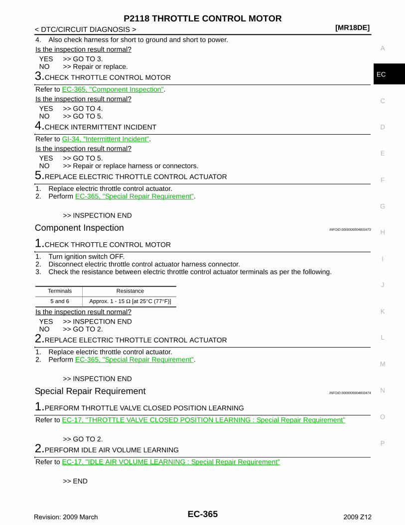
P2118 THROTTLE CONTROL MOTOR[MR18DE]
C
D
E
F
G
H
I
J
K
L
M
A
C
N
P
O
< DTC/CIRCUIT DIAGNOSIS >
E
4. Also check harness for short to ground and short to power.Is the inspection result normal?YES >> GO TO 3.NO >> Repair or replace.
3.CHECK THROTTLE CONTROL MOTOR
Refer to EC-365, "Component Inspection".Is the inspection result normal?YES >> GO TO 4.NO >> GO TO 5.
4.CHECK INTERMITTENT INCIDENT
Refer to GI-34, "Intermittent Incident".Is the inspection result normal?YES >> GO TO 5.NO >> Repair or replace harness or connectors.
5.REPLACE ELECTRIC THROTTLE CONTROL ACTUATOR
1. Replace electric throttle control actuator.2. Perform EC-365, "Special Repair Requirement".
>> INSPECTION END
Component Inspection INFOID:0000000004833473
1.CHECK THROTTLE CONTROL MOTOR
1. Turn ignition switch OFF.2. Disconnect electric throttle control actuator harness connector.3. Check the resistance between electric throttle control actuator terminals as per the following.
Is the inspection result normal?YES >> INSPECTION ENDNO >> GO TO 2.
2.REPLACE ELECTRIC THROTTLE CONTROL ACTUATOR
1. Replace electric throttle control actuator.2. Perform EC-365, "Special Repair Requirement".
>> INSPECTION END
Special Repair Requirement INFOID:0000000004833474
1.PERFORM THROTTLE VALVE CLOSED POSITION LEARNING
Refer to EC-17, "THROTTLE VALVE CLOSED POSITION LEARNING : Special Repair Requirement"
>> GO TO 2.
2.PERFORM IDLE AIR VOLUME LEARNING
Refer to EC-17, "IDLE AIR VOLUME LEARNING : Special Repair Requirement"
>> END
Terminals Resistance
5 and 6 Approx. 1 - 15 Ω [at 25°C (77°F)]
EC-365Revision: 2009 March 2009 Z12
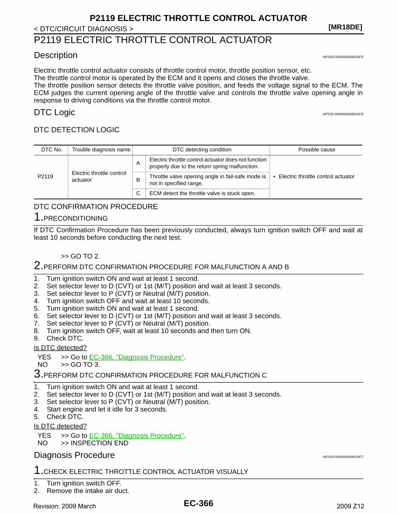
[MR18DE]P2119 ELECTRIC THROTTLE CONTROL ACTUATOR
< DTC/CIRCUIT DIAGNOSIS >
P2119 ELECTRIC THROTTLE CONTROL ACTUATOR
Description INFOID:0000000004833475
Electric throttle control actuator consists of throttle control motor, throttle position sensor, etc.The throttle control motor is operated by the ECM and it opens and closes the throttle valve.The throttle position sensor detects the throttle valve position, and feeds the voltage signal to the ECM. TheECM judges the current opening angle of the throttle valve and controls the throttle valve opening angle inresponse to driving conditions via the throttle control motor.
DTC Logic INFOID:0000000004833476
DTC DETECTION LOGIC
DTC CONFIRMATION PROCEDURE
1.PRECONDITIONING
If DTC Confirmation Procedure has been previously conducted, always turn ignition switch OFF and wait atleast 10 seconds before conducting the next test.
>> GO TO 2.
2.PERFORM DTC CONFIRMATION PROCEDURE FOR MALFUNCTION A AND B
1. Turn ignition switch ON and wait at least 1 second.2. Set selector lever to D (CVT) or 1st (M/T) position and wait at least 3 seconds.3. Set selector lever to P (CVT) or Neutral (M/T) position.4. Turn ignition switch OFF and wait at least 10 seconds.5. Turn ignition switch ON and wait at least 1 second.6. Set selector lever to D (CVT) or 1st (M/T) position and wait at least 3 seconds.7. Set selector lever to P (CVT) or Neutral (M/T) position.8. Turn ignition switch OFF, wait at least 10 seconds and then turn ON.9. Check DTC.Is DTC detected?YES >> Go to EC-366, "Diagnosis Procedure".NO >> GO TO 3.
3.PERFORM DTC CONFIRMATION PROCEDURE FOR MALFUNCTION C
1. Turn ignition switch ON and wait at least 1 second.2. Set selector lever to D (CVT) or 1st (M/T) position and wait at least 3 seconds.3. Set selector lever to P (CVT) or Neutral (M/T) position.4. Start engine and let it idle for 3 seconds.5. Check DTC.Is DTC detected?YES >> Go to EC-366, "Diagnosis Procedure".NO >> INSPECTION END
Diagnosis Procedure INFOID:0000000004833477
1.CHECK ELECTRIC THROTTLE CONTROL ACTUATOR VISUALLY
1. Turn ignition switch OFF.2. Remove the intake air duct.
DTC No. Trouble diagnosis name DTC detecting condition Possible cause
P2119Electric throttle control actuator
AElectric throttle control actuator does not function properly due to the return spring malfunction.
• Electric throttle control actuatorB
Throttle valve opening angle in fail-safe mode is not in specified range.
C ECM detect the throttle valve is stuck open.
EC-366Revision: 2009 March 2009 Z12
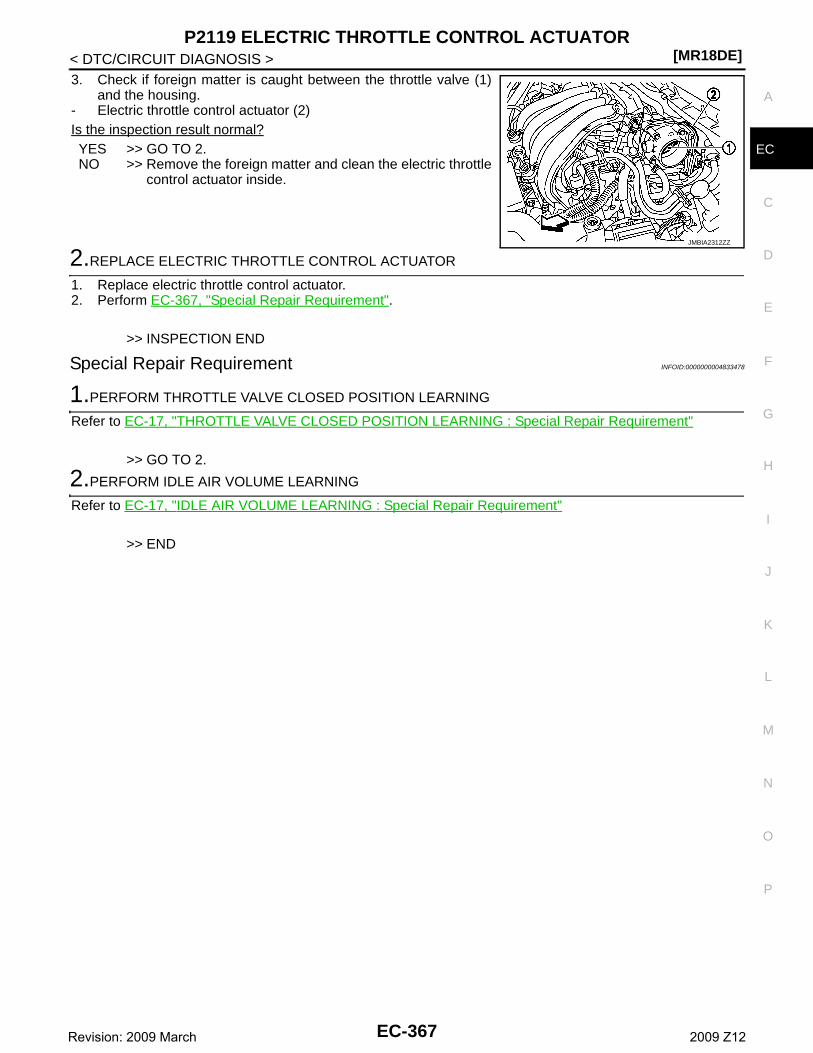
P2119 ELECTRIC THROTTLE CONTROL ACTUATOR[MR18DE]
C
D
E
F
G
H
I
J
K
L
M
A
C
N
P
O
< DTC/CIRCUIT DIAGNOSIS >
E
3. Check if foreign matter is caught between the throttle valve (1)and the housing.
- Electric throttle control actuator (2)Is the inspection result normal?YES >> GO TO 2.NO >> Remove the foreign matter and clean the electric throttle
control actuator inside.
2.REPLACE ELECTRIC THROTTLE CONTROL ACTUATOR
1. Replace electric throttle control actuator.2. Perform EC-367, "Special Repair Requirement".
>> INSPECTION END
Special Repair Requirement INFOID:0000000004833478
1.PERFORM THROTTLE VALVE CLOSED POSITION LEARNING
Refer to EC-17, "THROTTLE VALVE CLOSED POSITION LEARNING : Special Repair Requirement"
>> GO TO 2.
2.PERFORM IDLE AIR VOLUME LEARNING
Refer to EC-17, "IDLE AIR VOLUME LEARNING : Special Repair Requirement"
>> END
JMBIA2312ZZ
EC-367Revision: 2009 March 2009 Z12
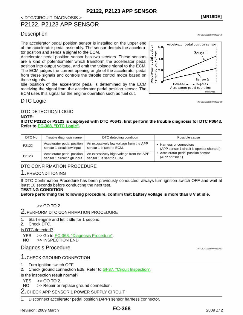
[MR18DE]P2122, P2123 APP SENSOR
< DTC/CIRCUIT DIAGNOSIS >
P2122, P2123 APP SENSOR
Description INFOID:0000000004833479
The accelerator pedal position sensor is installed on the upper endof the accelerator pedal assembly. The sensor detects the accelera-tor position and sends a signal to the ECM.Accelerator pedal position sensor has two sensors. These sensorsare a kind of potentiometer which transform the accelerator pedalposition into output voltage, and emit the voltage signal to the ECM.The ECM judges the current opening angle of the accelerator pedalfrom these signals and controls the throttle control motor based onthese signals.Idle position of the accelerator pedal is determined by the ECMreceiving the signal from the accelerator pedal position sensor. TheECM uses this signal for the engine operation such as fuel cut.
DTC Logic INFOID:0000000004833480
DTC DETECTION LOGICNOTE:If DTC P2122 or P2123 is displayed with DTC P0643, first perform the trouble diagnosis for DTC P0643.Refer to EC-308, "DTC Logic".
DTC CONFIRMATION PROCEDURE
1.PRECONDITIONING
If DTC Confirmation Procedure has been previously conducted, always turn ignition switch OFF and wait atleast 10 seconds before conducting the next test.TESTING CONDITION:Before performing the following procedure, confirm that battery voltage is more than 8 V at idle.
>> GO TO 2.
2.PERFORM DTC CONFIRMATION PROCEDURE
1. Start engine and let it idle for 1 second.2. Check DTC.Is DTC detected?YES >> Go to EC-368, "Diagnosis Procedure".NO >> INSPECTION END
Diagnosis Procedure INFOID:0000000004833482
1.CHECK GROUND CONNECTION
1. Turn ignition switch OFF.2. Check ground connection E38. Refer to GI-37, "Circuit Inspection".Is the inspection result normal?YES >> GO TO 2.NO >> Repair or replace ground connection.
2.CHECK APP SENSOR 1 POWER SUPPLY CIRCUIT
1. Disconnect accelerator pedal position (APP) sensor harness connector.
PBIB1741E
DTC No. Trouble diagnosis name DTC detecting condition Possible cause
P2122Accelerator pedal position sensor 1 circuit low input
An excessively low voltage from the APP sensor 1 is sent to ECM.
• Harness or connectors(APP sensor 1 circuit is open or shorted.)
• Accelerator pedal position sensor(APP sensor 1)P2123
Accelerator pedal position sensor 1 circuit high input
An excessively high voltage from the APP sensor 1 is sent to ECM.
EC-368Revision: 2009 March 2009 Z12
P2122, P2123 APP SENSOR[MR18DE]
C
D
E
F
G
H
I
J
K
L
M
A
C
N
P
O
< DTC/CIRCUIT DIAGNOSIS >
E
2. Turn ignition switch ON.3. Check the voltage between APP sensor harness connector and ground.
Is the inspection result normal?YES >> GO TO 3.NO >> Repair open circuit or short to ground or short to power in harness or connectors.
3.CHECK APP SENSOR 1 GROUND CIRCUIT FOR OPEN AND SHORT
1. Turn ignition switch OFF.2. Disconnect ECM harness connector.3. Check the continuity between APP sensor harness connector and ECM harness connector.
4. Also check harness for short to ground and short to power.Is the inspection result normal?YES >> GO TO 4.NO >> Repair open circuit or short to ground or short to power in harness or connectors.
4.CHECK APP SENSOR INPUT SIGNAL CIRCUIT FOR OPEN AND SHORT
1. Check the continuity between APP sensor harness connector and ECM harness connector.
2. Also check harness for short to ground and short to power.Is the inspection result normal?YES >> GO TO 5.NO >> Repair open circuit or short to ground or short to power in harness or connectors.
5.CHECK APP SENSOR
Refer to EC-370, "Component Inspection".Is the inspection result normal?YES >> GO TO 7.NO >> GO TO 6.
6.REPLACE ACCELERATOR PEDAL ASSEMBLY
1. Replace accelerator pedal assembly.2. Perform EC-370, "Special Repair Requirement".
>> INSPECTION END
7.CHECK INTERMITTENT INCIDENT
Refer to GI-34, "Intermittent Incident".
>> INSPECTION END
APP sensorGround Voltage
Connector Terminal
E110 4 Ground Approx. 5 V
APP sensor ECMContinuity
Connector Terminal Connector Terminal
E110 2 E16 111 Existed
APP sensor ECMContinuity
Connector Terminal Connector Terminal
E110 3 E16 110 Existed
EC-369Revision: 2009 March 2009 Z12
[MR18DE]P2122, P2123 APP SENSOR
< DTC/CIRCUIT DIAGNOSIS >
Component Inspection INFOID:0000000004833483
1.CHECK ACCELERATOR PEDAL POSITION SENSOR
1. Reconnect all harness connectors disconnected.2. Turn ignition switch ON.3. Check the voltage between ECM harness connector and ground.
Is the inspection result normal?YES >> INSPECTION ENDNO >> GO TO 2.
2.REPLACE ACCELERATOR PEDAL ASSEMBLY
1. Replace accelerator pedal assembly.2. Perform EC-370, "Special Repair Requirement".
>> INSPECTION END
Special Repair Requirement INFOID:0000000004833484
1.PERFORM ACCELERATOR PEDAL RELEASED POSITION LEARNING
Refer to EC-17, "ACCELERATOR PEDAL RELEASED POSITION LEARNING : Special Repair Requirement".
>> GO TO 2.
2.PERFORM THROTTLE VALVE CLOSED POSITION LEARNING
Refer to EC-17, "THROTTLE VALVE CLOSED POSITION LEARNING : Special Repair Requirement".
>> GO TO 3.
3.PERFORM IDLE AIR VOLUME LEARNING
Refer to EC-17, "IDLE AIR VOLUME LEARNING : Special Repair Requirement".
>> END
ECMGround Condition Voltage
Connector Terminal
E16
110(APP sensor 1
signal)Ground
Accelerator ped-al
Fully released 0.6 - 0.9 V
Fully depressed 3.9 - 4.7 V
103(APP sensor 2
signal)
Fully released 0.3 - 0.6 V
Fully depressed 1.95 - 2.4 V
EC-370Revision: 2009 March 2009 Z12
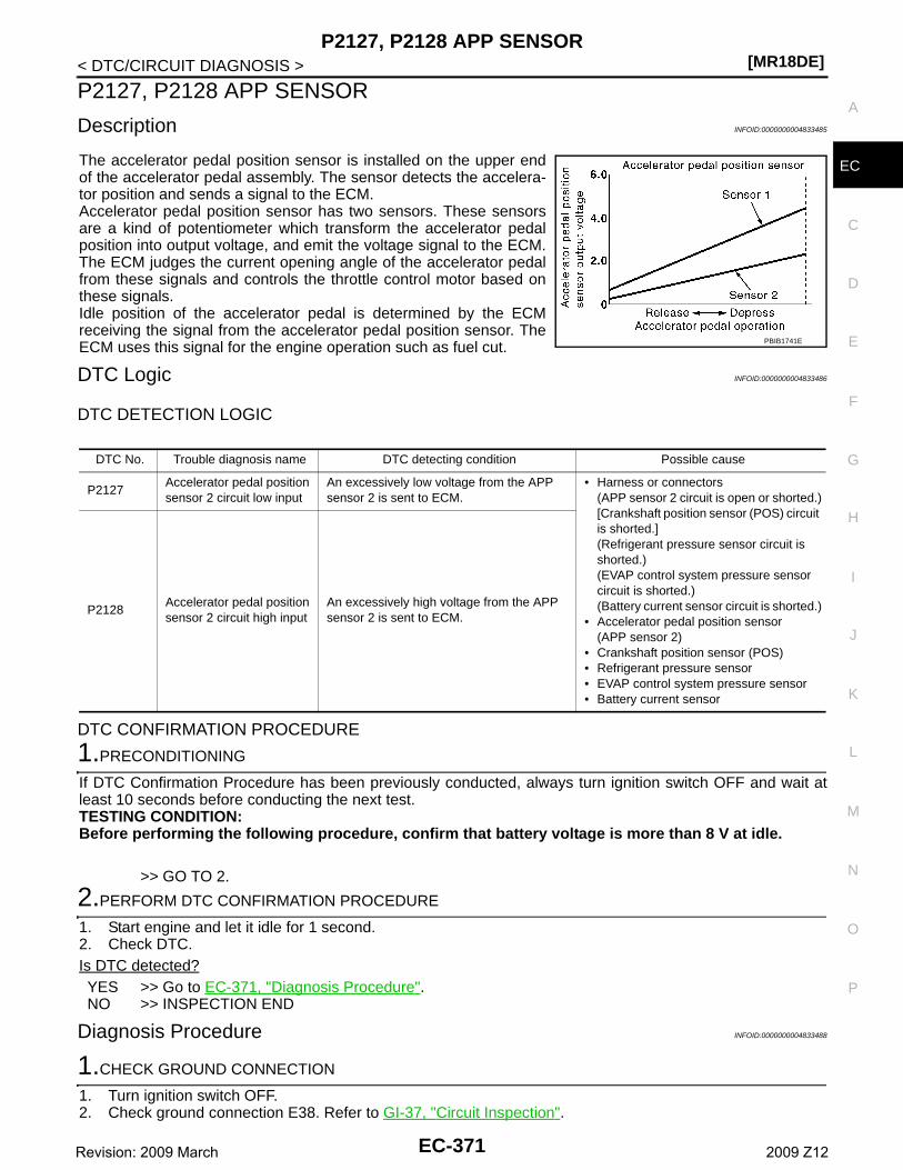
P2127, P2128 APP SENSOR[MR18DE]
C
D
E
F
G
H
I
J
K
L
M
A
C
N
P
O
< DTC/CIRCUIT DIAGNOSIS >
E
P2127, P2128 APP SENSOR
Description INFOID:0000000004833485
The accelerator pedal position sensor is installed on the upper endof the accelerator pedal assembly. The sensor detects the accelera-tor position and sends a signal to the ECM.Accelerator pedal position sensor has two sensors. These sensorsare a kind of potentiometer which transform the accelerator pedalposition into output voltage, and emit the voltage signal to the ECM.The ECM judges the current opening angle of the accelerator pedalfrom these signals and controls the throttle control motor based onthese signals.Idle position of the accelerator pedal is determined by the ECMreceiving the signal from the accelerator pedal position sensor. TheECM uses this signal for the engine operation such as fuel cut.
DTC Logic INFOID:0000000004833486
DTC DETECTION LOGIC
DTC CONFIRMATION PROCEDURE
1.PRECONDITIONING
If DTC Confirmation Procedure has been previously conducted, always turn ignition switch OFF and wait atleast 10 seconds before conducting the next test.TESTING CONDITION:Before performing the following procedure, confirm that battery voltage is more than 8 V at idle.
>> GO TO 2.
2.PERFORM DTC CONFIRMATION PROCEDURE
1. Start engine and let it idle for 1 second.2. Check DTC.Is DTC detected?YES >> Go to EC-371, "Diagnosis Procedure".NO >> INSPECTION END
Diagnosis Procedure INFOID:0000000004833488
1.CHECK GROUND CONNECTION
1. Turn ignition switch OFF.2. Check ground connection E38. Refer to GI-37, "Circuit Inspection".
PBIB1741E
DTC No. Trouble diagnosis name DTC detecting condition Possible cause
P2127Accelerator pedal position sensor 2 circuit low input
An excessively low voltage from the APP sensor 2 is sent to ECM.
• Harness or connectors(APP sensor 2 circuit is open or shorted.)[Crankshaft position sensor (POS) circuit is shorted.](Refrigerant pressure sensor circuit is shorted.)(EVAP control system pressure sensor circuit is shorted.)(Battery current sensor circuit is shorted.)
• Accelerator pedal position sensor(APP sensor 2)
• Crankshaft position sensor (POS)• Refrigerant pressure sensor• EVAP control system pressure sensor• Battery current sensor
P2128Accelerator pedal position sensor 2 circuit high input
An excessively high voltage from the APP sensor 2 is sent to ECM.
EC-371Revision: 2009 March 2009 Z12
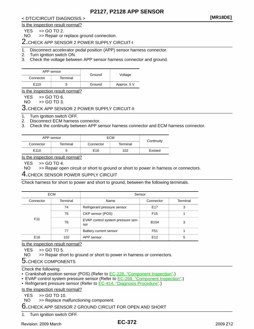
[MR18DE]P2127, P2128 APP SENSOR
< DTC/CIRCUIT DIAGNOSIS >Is the inspection result normal?YES >> GO TO 2.NO >> Repair or replace ground connection.
2.CHECK APP SENSOR 2 POWER SUPPLY CIRCUIT-I
1. Disconnect accelerator pedal position (APP) sensor harness connector.2. Turn ignition switch ON.3. Check the voltage between APP sensor harness connector and ground.
Is the inspection result normal?YES >> GO TO 6.NO >> GO TO 3.
3.CHECK APP SENSOR 2 POWER SUPPLY CIRCUIT-II
1. Turn ignition switch OFF.2. Disconnect ECM harness connector.3. Check the continuity between APP sensor harness connector and ECM harness connector.
Is the inspection result normal?YES >> GO TO 4.NO >> Repair open circuit or short to ground or short to power in harness or connectors.
4.CHECK SENSOR POWER SUPPLY CIRCUIT
Check harness for short to power and short to ground, between the following terminals.
Is the inspection result normal?YES >> GO TO 5.NO >> Repair short to ground or short to power in harness or connectors.
5.CHECK COMPONENTS
Check the following.• Crankshaft position sensor (POS) (Refer to EC-228, "Component Inspection".)• EVAP control system pressure sensor (Refer to EC-269, "Component Inspection".)• Refrigerant pressure sensor (Refer to EC-414, "Diagnosis Procedure".)Is the inspection result normal?YES >> GO TO 10.NO >> Replace malfunctioning component.
6.CHECK APP SENSOR 2 GROUND CIRCUIT FOR OPEN AND SHORT
1. Turn ignition switch OFF.
APP sensorGround Voltage
Connector Terminal
E110 5 Ground Approx. 5 V
APP sensor ECMContinuity
Connector Terminal Connector Terminal
E110 5 E16 102 Existed
ECM Sensor
Connector Terminal Name Connector Terminal
F11
74 Refrigerant pressure sensor E17 3
75 CKP sensor (POS) F15 1
76EVAP control system pressure sen-sor
B104 3
77 Battery current sensor F51 1
E16 102 APP sensor E12 5
EC-372Revision: 2009 March 2009 Z12
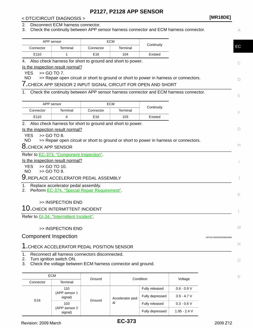
P2127, P2128 APP SENSOR[MR18DE]
C
D
E
F
G
H
I
J
K
L
M
A
C
N
P
O
< DTC/CIRCUIT DIAGNOSIS >
E
2. Disconnect ECM harness connector.3. Check the continuity between APP sensor harness connector and ECM harness connector.
4. Also check harness for short to ground and short to power.Is the inspection result normal?YES >> GO TO 7.NO >> Repair open circuit or short to ground or short to power in harness or connectors.
7.CHECK APP SENSOR 2 INPUT SIGNAL CIRCUIT FOR OPEN AND SHORT
1. Check the continuity between APP sensor harness connector and ECM harness connector.
2. Also check harness for short to ground and short to power.Is the inspection result normal?YES >> GO TO 8.NO >> Repair open circuit or short to ground or short to power in harness or connectors.
8.CHECK APP SENSOR
Refer to EC-373, "Component Inspection".Is the inspection result normal?YES >> GO TO 10.NO >> GO TO 9.
9.REPLACE ACCELERATOR PEDAL ASSEMBLY
1. Replace accelerator pedal assembly.2. Perform EC-374, "Special Repair Requirement".
>> INSPECTION END
10.CHECK INTERMITTENT INCIDENT
Refer to GI-34, "Intermittent Incident".
>> INSPECTION END
Component Inspection INFOID:0000000004833489
1.CHECK ACCELERATOR PEDAL POSITION SENSOR
1. Reconnect all harness connectors disconnected.2. Turn ignition switch ON.3. Check the voltage between ECM harness connector and ground.
APP sensor ECMContinuity
Connector Terminal Connector Terminal
E110 1 E16 104 Existed
APP sensor ECMContinuity
Connector Terminal Connector Terminal
E110 6 E16 103 Existed
ECMGround Condition Voltage
Connector Terminal
E16
110(APP sensor 1
signal)Ground
Accelerator ped-al
Fully released 0.6 - 0.9 V
Fully depressed 3.9 - 4.7 V
103(APP sensor 2
signal)
Fully released 0.3 - 0.6 V
Fully depressed 1.95 - 2.4 V
EC-373Revision: 2009 March 2009 Z12
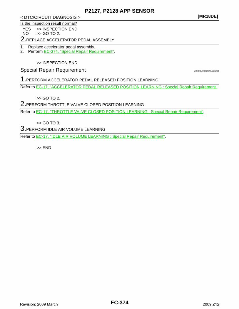
[MR18DE]P2127, P2128 APP SENSOR
< DTC/CIRCUIT DIAGNOSIS >Is the inspection result normal?YES >> INSPECTION ENDNO >> GO TO 2.
2.REPLACE ACCELERATOR PEDAL ASSEMBLY
1. Replace accelerator pedal assembly.2. Perform EC-374, "Special Repair Requirement".
>> INSPECTION END
Special Repair Requirement INFOID:0000000004833490
1.PERFORM ACCELERATOR PEDAL RELEASED POSITION LEARNING
Refer to EC-17, "ACCELERATOR PEDAL RELEASED POSITION LEARNING : Special Repair Requirement".
>> GO TO 2.
2.PERFORM THROTTLE VALVE CLOSED POSITION LEARNING
Refer to EC-17, "THROTTLE VALVE CLOSED POSITION LEARNING : Special Repair Requirement".
>> GO TO 3.
3.PERFORM IDLE AIR VOLUME LEARNING
Refer to EC-17, "IDLE AIR VOLUME LEARNING : Special Repair Requirement".
>> END
EC-374Revision: 2009 March 2009 Z12
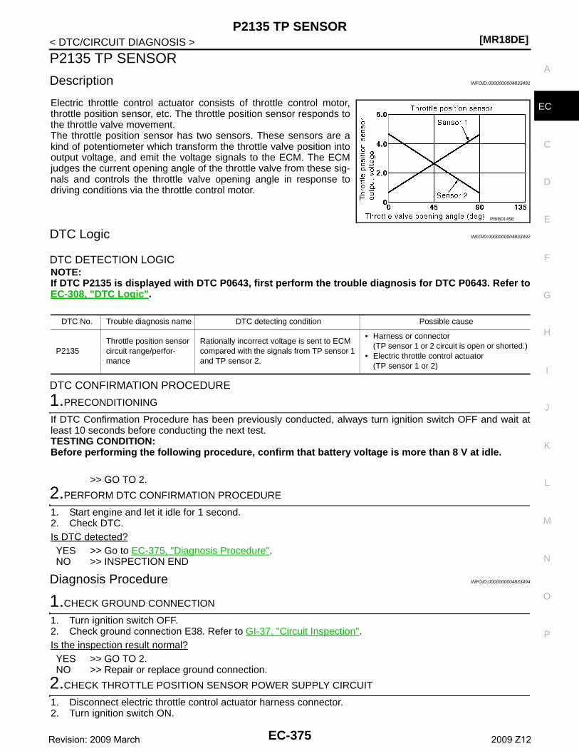
P2135 TP SENSOR[MR18DE]
C
D
E
F
G
H
I
J
K
L
M
A
C
N
P
O
< DTC/CIRCUIT DIAGNOSIS >
E
P2135 TP SENSOR
Description INFOID:0000000004833491
Electric throttle control actuator consists of throttle control motor,throttle position sensor, etc. The throttle position sensor responds tothe throttle valve movement. The throttle position sensor has two sensors. These sensors are akind of potentiometer which transform the throttle valve position intooutput voltage, and emit the voltage signals to the ECM. The ECMjudges the current opening angle of the throttle valve from these sig-nals and controls the throttle valve opening angle in response todriving conditions via the throttle control motor.
DTC Logic INFOID:0000000004833492
DTC DETECTION LOGICNOTE:If DTC P2135 is displayed with DTC P0643, first perform the trouble diagnosis for DTC P0643. Refer toEC-308, "DTC Logic".
DTC CONFIRMATION PROCEDURE
1.PRECONDITIONING
If DTC Confirmation Procedure has been previously conducted, always turn ignition switch OFF and wait atleast 10 seconds before conducting the next test.TESTING CONDITION:Before performing the following procedure, confirm that battery voltage is more than 8 V at idle.
>> GO TO 2.
2.PERFORM DTC CONFIRMATION PROCEDURE
1. Start engine and let it idle for 1 second.2. Check DTC.Is DTC detected?YES >> Go to EC-375, "Diagnosis Procedure".NO >> INSPECTION END
Diagnosis Procedure INFOID:0000000004833494
1.CHECK GROUND CONNECTION
1. Turn ignition switch OFF.2. Check ground connection E38. Refer to GI-37, "Circuit Inspection".Is the inspection result normal?YES >> GO TO 2.NO >> Repair or replace ground connection.
2.CHECK THROTTLE POSITION SENSOR POWER SUPPLY CIRCUIT
1. Disconnect electric throttle control actuator harness connector.2. Turn ignition switch ON.
PBIB0145E
DTC No. Trouble diagnosis name DTC detecting condition Possible cause
P2135Throttle position sensor circuit range/perfor-mance
Rationally incorrect voltage is sent to ECM compared with the signals from TP sensor 1 and TP sensor 2.
• Harness or connector(TP sensor 1 or 2 circuit is open or shorted.)
• Electric throttle control actuator(TP sensor 1 or 2)
EC-375Revision: 2009 March 2009 Z12
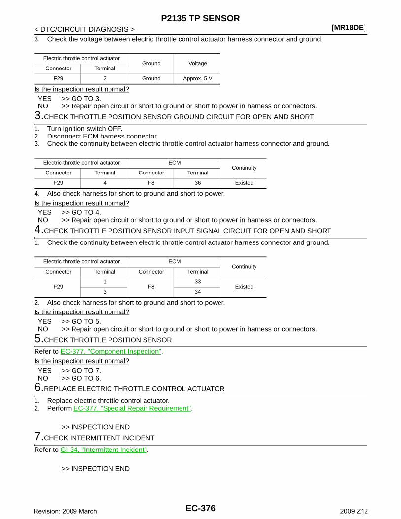
[MR18DE]P2135 TP SENSOR
< DTC/CIRCUIT DIAGNOSIS >3. Check the voltage between electric throttle control actuator harness connector and ground.
Is the inspection result normal?YES >> GO TO 3.NO >> Repair open circuit or short to ground or short to power in harness or connectors.
3.CHECK THROTTLE POSITION SENSOR GROUND CIRCUIT FOR OPEN AND SHORT
1. Turn ignition switch OFF.2. Disconnect ECM harness connector.3. Check the continuity between electric throttle control actuator harness connector and ground.
4. Also check harness for short to ground and short to power.Is the inspection result normal?YES >> GO TO 4.NO >> Repair open circuit or short to ground or short to power in harness or connectors.
4.CHECK THROTTLE POSITION SENSOR INPUT SIGNAL CIRCUIT FOR OPEN AND SHORT
1. Check the continuity between electric throttle control actuator harness connector and ground.
2. Also check harness for short to ground and short to power.Is the inspection result normal?YES >> GO TO 5.NO >> Repair open circuit or short to ground or short to power in harness or connectors.
5.CHECK THROTTLE POSITION SENSOR
Refer to EC-377, "Component Inspection".Is the inspection result normal?YES >> GO TO 7.NO >> GO TO 6.
6.REPLACE ELECTRIC THROTTLE CONTROL ACTUATOR
1. Replace electric throttle control actuator.2. Perform EC-377, "Special Repair Requirement".
>> INSPECTION END
7.CHECK INTERMITTENT INCIDENT
Refer to GI-34, "Intermittent Incident".
>> INSPECTION END
Electric throttle control actuatorGround Voltage
Connector Terminal
F29 2 Ground Approx. 5 V
Electric throttle control actuator ECMContinuity
Connector Terminal Connector Terminal
F29 4 F8 36 Existed
Electric throttle control actuator ECMContinuity
Connector Terminal Connector Terminal
F291
F833
Existed3 34
EC-376Revision: 2009 March 2009 Z12
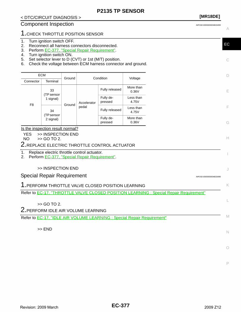
P2135 TP SENSOR[MR18DE]
C
D
E
F
G
H
I
J
K
L
M
A
C
N
P
O
< DTC/CIRCUIT DIAGNOSIS >
E
Component Inspection INFOID:0000000004833495
1.CHECK THROTTLE POSITION SENSOR
1. Turn ignition switch OFF.2. Reconnect all harness connectors disconnected.3. Perform EC-377, "Special Repair Requirement".4. Turn ignition switch ON.5. Set selector lever to D (CVT) or 1st (M/T) position. 6. Check the voltage between ECM harness connector and ground.
Is the inspection result normal?YES >> INSPECTION ENDNO >> GO TO 2.
2.REPLACE ELECTRIC THROTTLE CONTROL ACTUATOR
1. Replace electric throttle control actuator.2. Perform EC-377, "Special Repair Requirement".
>> INSPECTION END
Special Repair Requirement INFOID:0000000004833496
1.PERFORM THROTTLE VALVE CLOSED POSITION LEARNING
Refer to EC-17, "THROTTLE VALVE CLOSED POSITION LEARNING : Special Repair Requirement"
>> GO TO 2.
2.PERFORM IDLE AIR VOLUME LEARNING
Refer to EC-17, "IDLE AIR VOLUME LEARNING : Special Repair Requirement"
>> END
ECMGround Condition Voltage
Connector Terminal
F8
33(TP sensor 1 signal)
GroundAccelerator pedal
Fully releasedMore than
0.36V
Fully de-pressed
Less than 4.75V
34 (TP sensor
2 signal)
Fully releasedLess than
4.75V
Fully de-pressed
More than 0.36V
EC-377Revision: 2009 March 2009 Z12
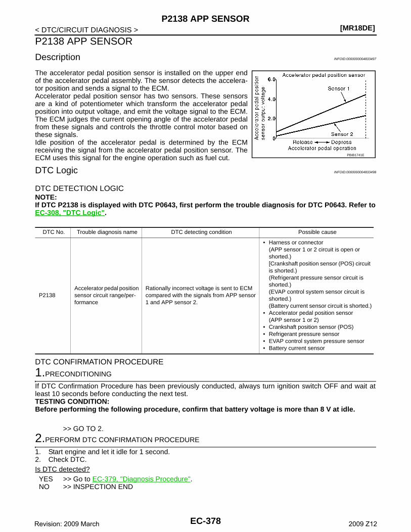
[MR18DE]P2138 APP SENSOR
< DTC/CIRCUIT DIAGNOSIS >
P2138 APP SENSOR
Description INFOID:0000000004833497
The accelerator pedal position sensor is installed on the upper endof the accelerator pedal assembly. The sensor detects the accelera-tor position and sends a signal to the ECM.Accelerator pedal position sensor has two sensors. These sensorsare a kind of potentiometer which transform the accelerator pedalposition into output voltage, and emit the voltage signal to the ECM.The ECM judges the current opening angle of the accelerator pedalfrom these signals and controls the throttle control motor based onthese signals.Idle position of the accelerator pedal is determined by the ECMreceiving the signal from the accelerator pedal position sensor. TheECM uses this signal for the engine operation such as fuel cut.
DTC Logic INFOID:0000000004833498
DTC DETECTION LOGICNOTE:If DTC P2138 is displayed with DTC P0643, first perform the trouble diagnosis for DTC P0643. Refer toEC-308, "DTC Logic".
DTC CONFIRMATION PROCEDURE
1.PRECONDITIONING
If DTC Confirmation Procedure has been previously conducted, always turn ignition switch OFF and wait atleast 10 seconds before conducting the next test.TESTING CONDITION:Before performing the following procedure, confirm that battery voltage is more than 8 V at idle.
>> GO TO 2.
2.PERFORM DTC CONFIRMATION PROCEDURE
1. Start engine and let it idle for 1 second.2. Check DTC.Is DTC detected?YES >> Go to EC-379, "Diagnosis Procedure".NO >> INSPECTION END
PBIB1741E
DTC No. Trouble diagnosis name DTC detecting condition Possible cause
P2138Accelerator pedal position sensor circuit range/per-formance
Rationally incorrect voltage is sent to ECM compared with the signals from APP sensor 1 and APP sensor 2.
• Harness or connector(APP sensor 1 or 2 circuit is open or shorted.)[Crankshaft position sensor (POS) circuit is shorted.)(Refrigerant pressure sensor circuit is shorted.)(EVAP control system sensor circuit is shorted.)(Battery current sensor circuit is shorted.)
• Accelerator pedal position sensor(APP sensor 1 or 2)
• Crankshaft position sensor (POS)• Refrigerant pressure sensor• EVAP control system pressure sensor• Battery current sensor
EC-378Revision: 2009 March 2009 Z12
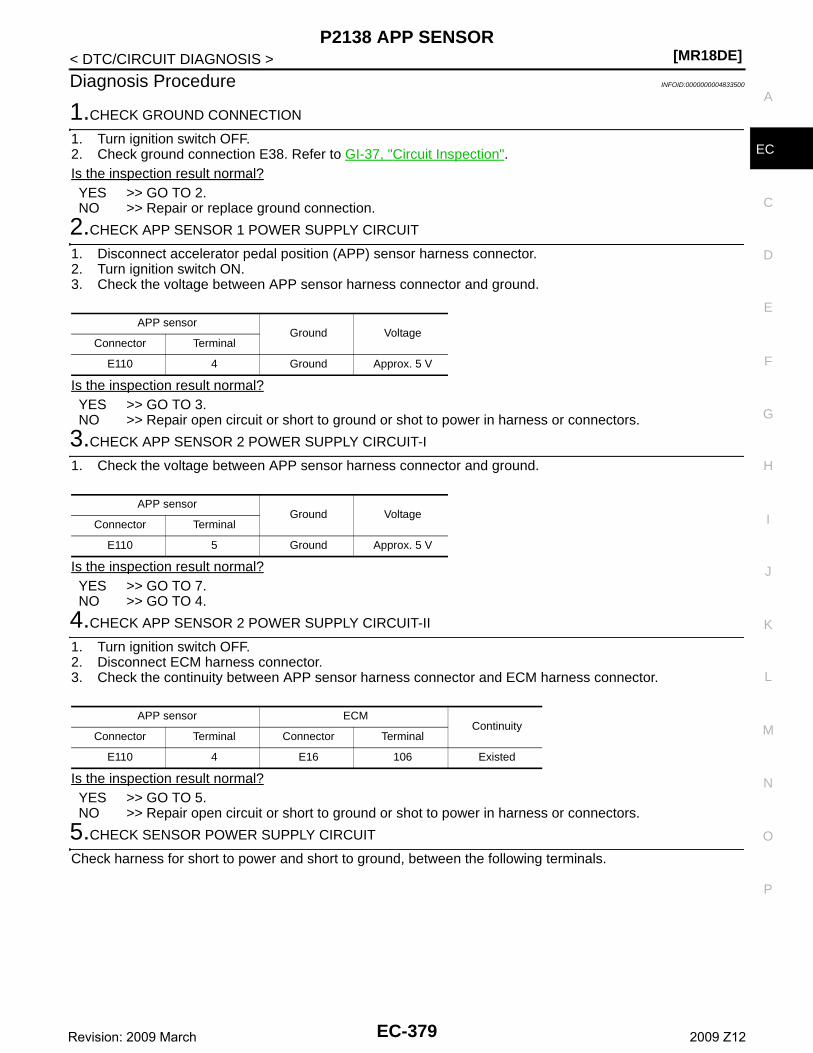
P2138 APP SENSOR[MR18DE]
C
D
E
F
G
H
I
J
K
L
M
A
C
N
P
O
< DTC/CIRCUIT DIAGNOSIS >
E
Diagnosis Procedure INFOID:0000000004833500
1.CHECK GROUND CONNECTION
1. Turn ignition switch OFF.2. Check ground connection E38. Refer to GI-37, "Circuit Inspection".Is the inspection result normal?YES >> GO TO 2.NO >> Repair or replace ground connection.
2.CHECK APP SENSOR 1 POWER SUPPLY CIRCUIT
1. Disconnect accelerator pedal position (APP) sensor harness connector.2. Turn ignition switch ON.3. Check the voltage between APP sensor harness connector and ground.
Is the inspection result normal?YES >> GO TO 3.NO >> Repair open circuit or short to ground or shot to power in harness or connectors.
3.CHECK APP SENSOR 2 POWER SUPPLY CIRCUIT-I
1. Check the voltage between APP sensor harness connector and ground.
Is the inspection result normal?YES >> GO TO 7.NO >> GO TO 4.
4.CHECK APP SENSOR 2 POWER SUPPLY CIRCUIT-II
1. Turn ignition switch OFF.2. Disconnect ECM harness connector.3. Check the continuity between APP sensor harness connector and ECM harness connector.
Is the inspection result normal?YES >> GO TO 5.NO >> Repair open circuit or short to ground or shot to power in harness or connectors.
5.CHECK SENSOR POWER SUPPLY CIRCUIT
Check harness for short to power and short to ground, between the following terminals.
APP sensorGround Voltage
Connector Terminal
E110 4 Ground Approx. 5 V
APP sensorGround Voltage
Connector Terminal
E110 5 Ground Approx. 5 V
APP sensor ECMContinuity
Connector Terminal Connector Terminal
E110 4 E16 106 Existed
EC-379Revision: 2009 March 2009 Z12
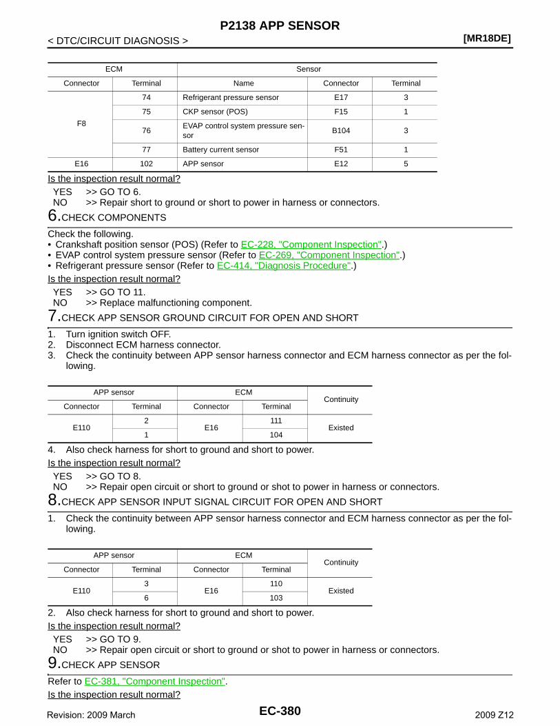
[MR18DE]P2138 APP SENSOR
< DTC/CIRCUIT DIAGNOSIS >
Is the inspection result normal?YES >> GO TO 6.NO >> Repair short to ground or short to power in harness or connectors.
6.CHECK COMPONENTS
Check the following.• Crankshaft position sensor (POS) (Refer to EC-228, "Component Inspection".)• EVAP control system pressure sensor (Refer to EC-269, "Component Inspection".)• Refrigerant pressure sensor (Refer to EC-414, "Diagnosis Procedure".)Is the inspection result normal?YES >> GO TO 11.NO >> Replace malfunctioning component.
7.CHECK APP SENSOR GROUND CIRCUIT FOR OPEN AND SHORT
1. Turn ignition switch OFF.2. Disconnect ECM harness connector.3. Check the continuity between APP sensor harness connector and ECM harness connector as per the fol-
lowing.
4. Also check harness for short to ground and short to power.Is the inspection result normal?YES >> GO TO 8.NO >> Repair open circuit or short to ground or shot to power in harness or connectors.
8.CHECK APP SENSOR INPUT SIGNAL CIRCUIT FOR OPEN AND SHORT
1. Check the continuity between APP sensor harness connector and ECM harness connector as per the fol-lowing.
2. Also check harness for short to ground and short to power.Is the inspection result normal?YES >> GO TO 9.NO >> Repair open circuit or short to ground or shot to power in harness or connectors.
9.CHECK APP SENSOR
Refer to EC-381, "Component Inspection".Is the inspection result normal?
ECM Sensor
Connector Terminal Name Connector Terminal
F8
74 Refrigerant pressure sensor E17 3
75 CKP sensor (POS) F15 1
76EVAP control system pressure sen-sor
B104 3
77 Battery current sensor F51 1
E16 102 APP sensor E12 5
APP sensor ECMContinuity
Connector Terminal Connector Terminal
E1102
E16111
Existed1 104
APP sensor ECMContinuity
Connector Terminal Connector Terminal
E1103
E16110
Existed6 103
EC-380Revision: 2009 March 2009 Z12
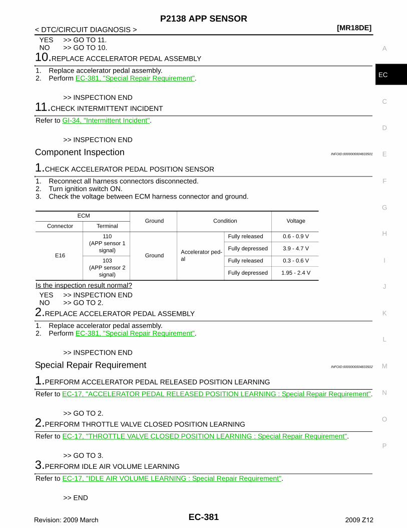
P2138 APP SENSOR[MR18DE]
C
D
E
F
G
H
I
J
K
L
M
A
C
N
P
O
< DTC/CIRCUIT DIAGNOSIS >
E
YES >> GO TO 11.NO >> GO TO 10.
10.REPLACE ACCELERATOR PEDAL ASSEMBLY
1. Replace accelerator pedal assembly.2. Perform EC-381, "Special Repair Requirement".
>> INSPECTION END
11.CHECK INTERMITTENT INCIDENT
Refer to GI-34, "Intermittent Incident".
>> INSPECTION END
Component Inspection INFOID:0000000004833501
1.CHECK ACCELERATOR PEDAL POSITION SENSOR
1. Reconnect all harness connectors disconnected.2. Turn ignition switch ON.3. Check the voltage between ECM harness connector and ground.
Is the inspection result normal?YES >> INSPECTION ENDNO >> GO TO 2.
2.REPLACE ACCELERATOR PEDAL ASSEMBLY
1. Replace accelerator pedal assembly.2. Perform EC-381, "Special Repair Requirement".
>> INSPECTION END
Special Repair Requirement INFOID:0000000004833502
1.PERFORM ACCELERATOR PEDAL RELEASED POSITION LEARNING
Refer to EC-17, "ACCELERATOR PEDAL RELEASED POSITION LEARNING : Special Repair Requirement".
>> GO TO 2.
2.PERFORM THROTTLE VALVE CLOSED POSITION LEARNING
Refer to EC-17, "THROTTLE VALVE CLOSED POSITION LEARNING : Special Repair Requirement".
>> GO TO 3.
3.PERFORM IDLE AIR VOLUME LEARNING
Refer to EC-17, "IDLE AIR VOLUME LEARNING : Special Repair Requirement".
>> END
ECMGround Condition Voltage
Connector Terminal
E16
110(APP sensor 1
signal)Ground
Accelerator ped-al
Fully released 0.6 - 0.9 V
Fully depressed 3.9 - 4.7 V
103(APP sensor 2
signal)
Fully released 0.3 - 0.6 V
Fully depressed 1.95 - 2.4 V
EC-381Revision: 2009 March 2009 Z12
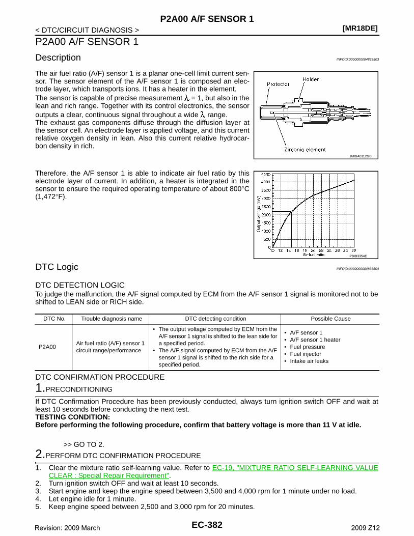
[MR18DE]P2A00 A/F SENSOR 1
< DTC/CIRCUIT DIAGNOSIS >
P2A00 A/F SENSOR 1
Description INFOID:0000000004833503
The air fuel ratio (A/F) sensor 1 is a planar one-cell limit current sen-sor. The sensor element of the A/F sensor 1 is composed an elec-trode layer, which transports ions. It has a heater in the element.The sensor is capable of precise measurement = 1, but also in thelean and rich range. Together with its control electronics, the sensoroutputs a clear, continuous signal throughout a wide range.The exhaust gas components diffuse through the diffusion layer atthe sensor cell. An electrode layer is applied voltage, and this currentrelative oxygen density in lean. Also this current relative hydrocar-bon density in rich.
Therefore, the A/F sensor 1 is able to indicate air fuel ratio by thiselectrode layer of current. In addition, a heater is integrated in thesensor to ensure the required operating temperature of about 800°C(1,472°F).
DTC Logic INFOID:0000000004833504
DTC DETECTION LOGICTo judge the malfunction, the A/F signal computed by ECM from the A/F sensor 1 signal is monitored not to beshifted to LEAN side or RICH side.
DTC CONFIRMATION PROCEDURE
1.PRECONDITIONING
If DTC Confirmation Procedure has been previously conducted, always turn ignition switch OFF and wait atleast 10 seconds before conducting the next test.TESTING CONDITION:Before performing the following procedure, confirm that battery voltage is more than 11 V at idle.
>> GO TO 2.
2.PERFORM DTC CONFIRMATION PROCEDURE
1. Clear the mixture ratio self-learning value. Refer to EC-19, "MIXTURE RATIO SELF-LEARNING VALUECLEAR : Special Repair Requirement".
2. Turn ignition switch OFF and wait at least 10 seconds.3. Start engine and keep the engine speed between 3,500 and 4,000 rpm for 1 minute under no load.4. Let engine idle for 1 minute.5. Keep engine speed between 2,500 and 3,000 rpm for 20 minutes.
JMBIA0112GB
PBIB3354E
DTC No. Trouble diagnosis name DTC detecting condition Possible Cause
P2A00Air fuel ratio (A/F) sensor 1 circuit range/performance
• The output voltage computed by ECM from the A/F sensor 1 signal is shifted to the lean side for a specified period.
• The A/F signal computed by ECM from the A/F sensor 1 signal is shifted to the rich side for a specified period.
• A/F sensor 1• A/F sensor 1 heater• Fuel pressure• Fuel injector• Intake air leaks
EC-382Revision: 2009 March 2009 Z12
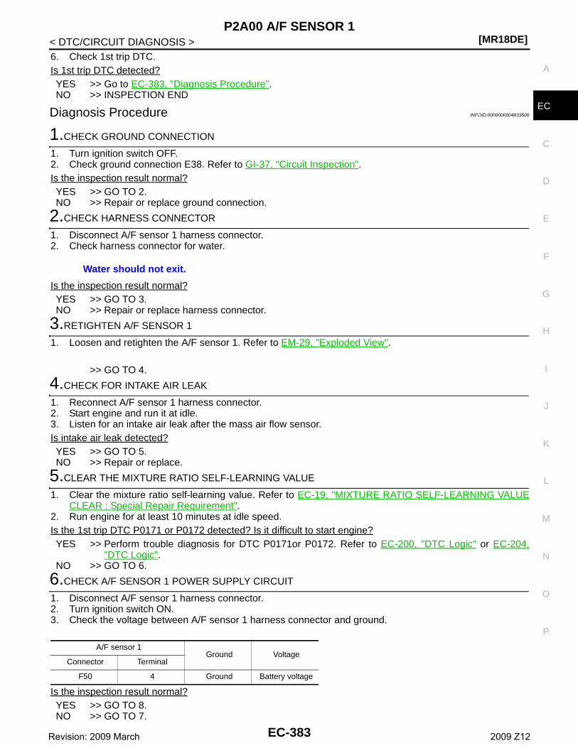
P2A00 A/F SENSOR 1[MR18DE]
C
D
E
F
G
H
I
J
K
L
M
A
C
N
P
O
< DTC/CIRCUIT DIAGNOSIS >
E
6. Check 1st trip DTC.Is 1st trip DTC detected?YES >> Go to EC-383, "Diagnosis Procedure".NO >> INSPECTION END
Diagnosis Procedure INFOID:0000000004833506
1.CHECK GROUND CONNECTION
1. Turn ignition switch OFF.2. Check ground connection E38. Refer to GI-37, "Circuit Inspection".Is the inspection result normal?YES >> GO TO 2.NO >> Repair or replace ground connection.
2.CHECK HARNESS CONNECTOR
1. Disconnect A/F sensor 1 harness connector.2. Check harness connector for water.
Is the inspection result normal?YES >> GO TO 3.NO >> Repair or replace harness connector.
3.RETIGHTEN A/F SENSOR 1
1. Loosen and retighten the A/F sensor 1. Refer to EM-29, "Exploded View".
>> GO TO 4.
4.CHECK FOR INTAKE AIR LEAK
1. Reconnect A/F sensor 1 harness connector.2. Start engine and run it at idle.3. Listen for an intake air leak after the mass air flow sensor.Is intake air leak detected?YES >> GO TO 5.NO >> Repair or replace.
5.CLEAR THE MIXTURE RATIO SELF-LEARNING VALUE
1. Clear the mixture ratio self-learning value. Refer to EC-19, "MIXTURE RATIO SELF-LEARNING VALUECLEAR : Special Repair Requirement".
2. Run engine for at least 10 minutes at idle speed.Is the 1st trip DTC P0171 or P0172 detected? Is it difficult to start engine?YES >> Perform trouble diagnosis for DTC P0171or P0172. Refer to EC-200, "DTC Logic" or EC-204,
"DTC Logic".NO >> GO TO 6.
6.CHECK A/F SENSOR 1 POWER SUPPLY CIRCUIT
1. Disconnect A/F sensor 1 harness connector.2. Turn ignition switch ON.3. Check the voltage between A/F sensor 1 harness connector and ground.
Is the inspection result normal?YES >> GO TO 8.NO >> GO TO 7.
Water should not exit.
A/F sensor 1Ground Voltage
Connector Terminal
F50 4 Ground Battery voltage
EC-383Revision: 2009 March 2009 Z12
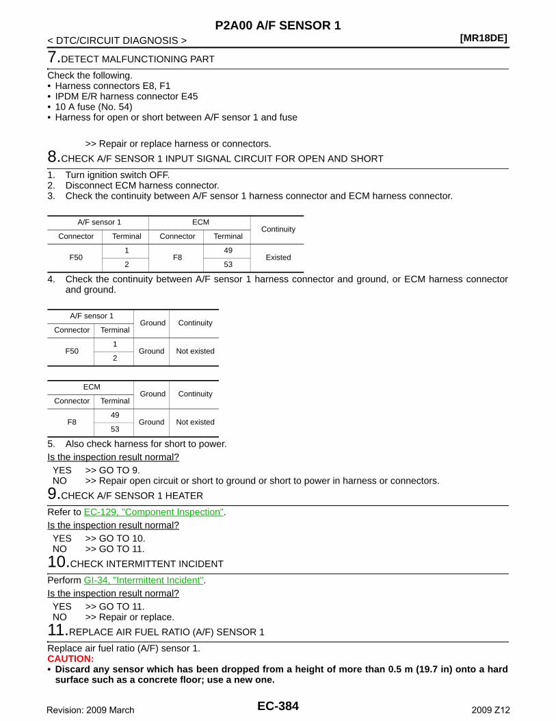
[MR18DE]P2A00 A/F SENSOR 1
< DTC/CIRCUIT DIAGNOSIS >
7.DETECT MALFUNCTIONING PART
Check the following.• Harness connectors E8, F1• IPDM E/R harness connector E45• 10 A fuse (No. 54)• Harness for open or short between A/F sensor 1 and fuse
>> Repair or replace harness or connectors.
8.CHECK A/F SENSOR 1 INPUT SIGNAL CIRCUIT FOR OPEN AND SHORT
1. Turn ignition switch OFF.2. Disconnect ECM harness connector.3. Check the continuity between A/F sensor 1 harness connector and ECM harness connector.
4. Check the continuity between A/F sensor 1 harness connector and ground, or ECM harness connectorand ground.
5. Also check harness for short to power.Is the inspection result normal?YES >> GO TO 9.NO >> Repair open circuit or short to ground or short to power in harness or connectors.
9.CHECK A/F SENSOR 1 HEATER
Refer to EC-129, "Component Inspection".Is the inspection result normal?YES >> GO TO 10.NO >> GO TO 11.
10.CHECK INTERMITTENT INCIDENT
Perform GI-34, "Intermittent Incident".Is the inspection result normal?YES >> GO TO 11.NO >> Repair or replace.
11.REPLACE AIR FUEL RATIO (A/F) SENSOR 1
Replace air fuel ratio (A/F) sensor 1.CAUTION:• Discard any sensor which has been dropped from a height of more than 0.5 m (19.7 in) onto a hard
surface such as a concrete floor; use a new one.
A/F sensor 1 ECMContinuity
Connector Terminal Connector Terminal
F501
F849
Existed2 53
A/F sensor 1Ground Continuity
Connector Terminal
F501
Ground Not existed2
ECMGround Continuity
Connector Terminal
F849
Ground Not existed53
EC-384Revision: 2009 March 2009 Z12
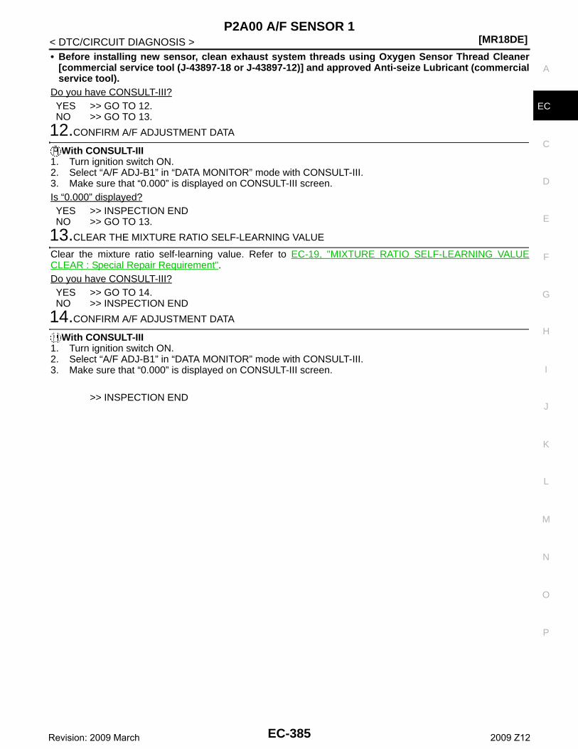
P2A00 A/F SENSOR 1[MR18DE]
C
D
E
F
G
H
I
J
K
L
M
A
C
N
P
O
< DTC/CIRCUIT DIAGNOSIS >
E
• Before installing new sensor, clean exhaust system threads using Oxygen Sensor Thread Cleaner[commercial service tool (J-43897-18 or J-43897-12)] and approved Anti-seize Lubricant (commercialservice tool).
Do you have CONSULT-III?YES >> GO TO 12.NO >> GO TO 13.
12.CONFIRM A/F ADJUSTMENT DATA
With CONSULT-III1. Turn ignition switch ON.2. Select “A/F ADJ-B1” in “DATA MONITOR” mode with CONSULT-III.3. Make sure that “0.000” is displayed on CONSULT-III screen.Is “0.000” displayed?YES >> INSPECTION ENDNO >> GO TO 13.
13.CLEAR THE MIXTURE RATIO SELF-LEARNING VALUE
Clear the mixture ratio self-learning value. Refer to EC-19, "MIXTURE RATIO SELF-LEARNING VALUECLEAR : Special Repair Requirement".Do you have CONSULT-III?YES >> GO TO 14.NO >> INSPECTION END
14.CONFIRM A/F ADJUSTMENT DATA
With CONSULT-III1. Turn ignition switch ON.2. Select “A/F ADJ-B1” in “DATA MONITOR” mode with CONSULT-III.3. Make sure that “0.000” is displayed on CONSULT-III screen.
>> INSPECTION END
EC-385Revision: 2009 March 2009 Z12
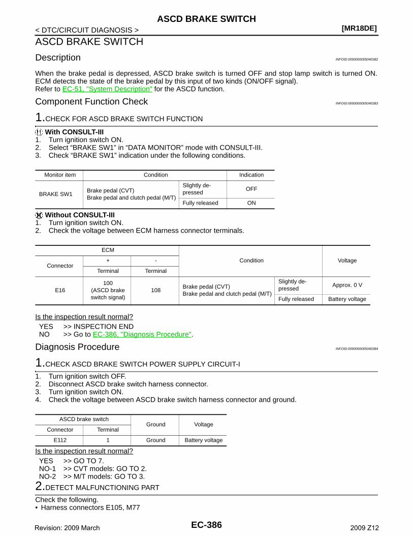
[MR18DE]ASCD BRAKE SWITCH
< DTC/CIRCUIT DIAGNOSIS >
ASCD BRAKE SWITCH
Description INFOID:0000000005040382
When the brake pedal is depressed, ASCD brake switch is turned OFF and stop lamp switch is turned ON.ECM detects the state of the brake pedal by this input of two kinds (ON/OFF signal).Refer to EC-51, "System Description" for the ASCD function.
Component Function Check INFOID:0000000005040383
1.CHECK FOR ASCD BRAKE SWITCH FUNCTION
With CONSULT-III1. Turn ignition switch ON.2. Select “BRAKE SW1” in “DATA MONITOR” mode with CONSULT-III.3. Check “BRAKE SW1” indication under the following conditions.
Without CONSULT-III1. Turn ignition switch ON.2. Check the voltage between ECM harness connector terminals.
Is the inspection result normal?YES >> INSPECTION ENDNO >> Go to EC-386, "Diagnosis Procedure".
Diagnosis Procedure INFOID:0000000005040384
1.CHECK ASCD BRAKE SWITCH POWER SUPPLY CIRCUIT-I
1. Turn ignition switch OFF.2. Disconnect ASCD brake switch harness connector.3. Turn ignition switch ON.4. Check the voltage between ASCD brake switch harness connector and ground.
Is the inspection result normal?YES >> GO TO 7.NO-1 >> CVT models: GO TO 2.NO-2 >> M/T models: GO TO 3.
2.DETECT MALFUNCTIONING PART
Check the following.• Harness connectors E105, M77
Monitor item Condition Indication
BRAKE SW1Brake pedal (CVT)Brake pedal and clutch pedal (M/T)
Slightly de-pressed
OFF
Fully released ON
ECM
Condition VoltageConnector
+ -
Terminal Terminal
E16100
(ASCD brake switch signal)
108Brake pedal (CVT)Brake pedal and clutch pedal (M/T)
Slightly de-pressed
Approx. 0 V
Fully released Battery voltage
ASCD brake switchGround Voltage
Connector Terminal
E112 1 Ground Battery voltage
EC-386Revision: 2009 March 2009 Z12
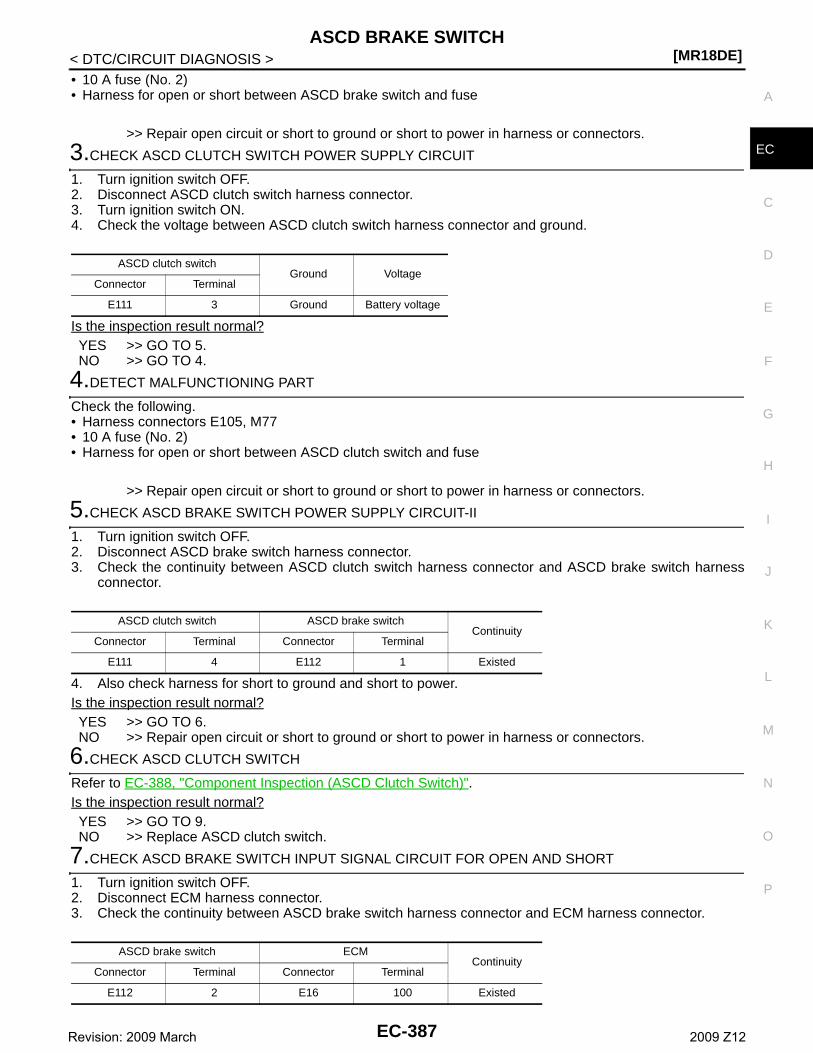
ASCD BRAKE SWITCH[MR18DE]
C
D
E
F
G
H
I
J
K
L
M
A
C
N
P
O
< DTC/CIRCUIT DIAGNOSIS >
E
• 10 A fuse (No. 2)• Harness for open or short between ASCD brake switch and fuse
>> Repair open circuit or short to ground or short to power in harness or connectors.
3.CHECK ASCD CLUTCH SWITCH POWER SUPPLY CIRCUIT
1. Turn ignition switch OFF.2. Disconnect ASCD clutch switch harness connector.3. Turn ignition switch ON.4. Check the voltage between ASCD clutch switch harness connector and ground.
Is the inspection result normal?YES >> GO TO 5.NO >> GO TO 4.
4.DETECT MALFUNCTIONING PART
Check the following.• Harness connectors E105, M77• 10 A fuse (No. 2)• Harness for open or short between ASCD clutch switch and fuse
>> Repair open circuit or short to ground or short to power in harness or connectors.
5.CHECK ASCD BRAKE SWITCH POWER SUPPLY CIRCUIT-II
1. Turn ignition switch OFF.2. Disconnect ASCD brake switch harness connector.3. Check the continuity between ASCD clutch switch harness connector and ASCD brake switch harness
connector.
4. Also check harness for short to ground and short to power.Is the inspection result normal?YES >> GO TO 6.NO >> Repair open circuit or short to ground or short to power in harness or connectors.
6.CHECK ASCD CLUTCH SWITCH
Refer to EC-388, "Component Inspection (ASCD Clutch Switch)".Is the inspection result normal?YES >> GO TO 9.NO >> Replace ASCD clutch switch.
7.CHECK ASCD BRAKE SWITCH INPUT SIGNAL CIRCUIT FOR OPEN AND SHORT
1. Turn ignition switch OFF.2. Disconnect ECM harness connector.3. Check the continuity between ASCD brake switch harness connector and ECM harness connector.
ASCD clutch switchGround Voltage
Connector Terminal
E111 3 Ground Battery voltage
ASCD clutch switch ASCD brake switchContinuity
Connector Terminal Connector Terminal
E111 4 E112 1 Existed
ASCD brake switch ECMContinuity
Connector Terminal Connector Terminal
E112 2 E16 100 Existed
EC-387Revision: 2009 March 2009 Z12
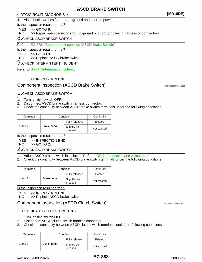
[MR18DE]ASCD BRAKE SWITCH
< DTC/CIRCUIT DIAGNOSIS >4. Also check harness for short to ground and short to power.Is the inspection result normal?YES >> GO TO 8.NO >> Repair open circuit or short to ground or short to power in harness or connectors.
8.CHECK ASCD BRAKE SWITCH
Refer to EC-388, "Component Inspection (ASCD Brake Switch)".Is the inspection result normal?YES >> GO TO 9.NO >> Replace ASCD brake switch.
9.CHECK INTERMITTENT INCIDENT
Refer to GI-34, "Intermittent Incident".
>> INSPECTION END
Component Inspection (ASCD Brake Switch) INFOID:0000000005040385
1.CHECK ASCD BRAKE SWITCH-I
1. Turn ignition switch OFF.2. Disconnect ASCD brake switch harness connector.3. Check the continuity between ASCD brake switch terminals under the following conditions.
Is the inspection result normal?YES >> INSPECTION ENDNO >> GO TO 2.
2.CHECK ASCD BRAKE SWITCH-II
1. Adjust ASCD brake switch installation. Refer to BR-7, "Inspection and Adjustment".2. Check the continuity between ASCD brake switch terminals under the following conditions.
Is the inspection result normal?YES >> INSPECTION ENDNO >> Replace ASCD brake switch.
Component Inspection (ASCD Clutch Switch) INFOID:0000000005040386
1.CHECK ASCD CLUTCH SWITCH-I
1. Turn ignition switch OFF.2. Disconnect ASCD clutch switch harness connector.3. Check the continuity between ASCD clutch switch terminals under the following conditions.
Terminals Condition Continuity
1 and 2 Brake pedal
Fully released Existed
Slightly de-pressed
Not existed
Terminals Condition Continuity
1 and 2 Brake pedal
Fully released Existed
Slightly de-pressed
Not existed
Terminals Condition Continuity
1 and 2 Clutch pedal
Fully released Existed
Slightly de-pressed
Not existed
EC-388Revision: 2009 March 2009 Z12
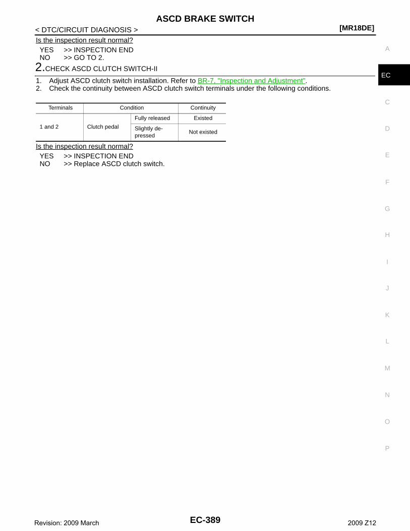
ASCD BRAKE SWITCH[MR18DE]
C
D
E
F
G
H
I
J
K
L
M
A
C
N
P
O
< DTC/CIRCUIT DIAGNOSIS >
E
Is the inspection result normal?YES >> INSPECTION ENDNO >> GO TO 2.
2.CHECK ASCD CLUTCH SWITCH-II
1. Adjust ASCD clutch switch installation. Refer to BR-7, "Inspection and Adjustment".2. Check the continuity between ASCD clutch switch terminals under the following conditions.
Is the inspection result normal?YES >> INSPECTION ENDNO >> Replace ASCD clutch switch.
Terminals Condition Continuity
1 and 2 Clutch pedal
Fully released Existed
Slightly de-pressed
Not existed
EC-389Revision: 2009 March 2009 Z12
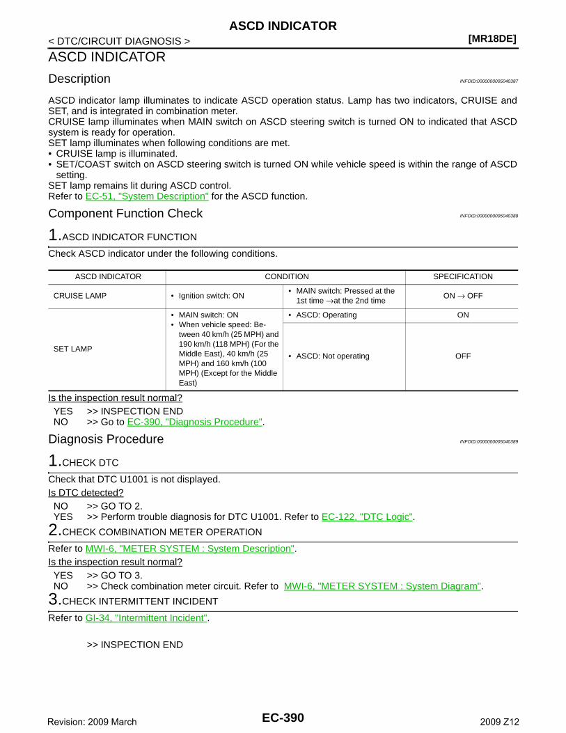
[MR18DE]ASCD INDICATOR
< DTC/CIRCUIT DIAGNOSIS >
ASCD INDICATOR
Description INFOID:0000000005040387
ASCD indicator lamp illuminates to indicate ASCD operation status. Lamp has two indicators, CRUISE andSET, and is integrated in combination meter.CRUISE lamp illuminates when MAIN switch on ASCD steering switch is turned ON to indicated that ASCDsystem is ready for operation.SET lamp illuminates when following conditions are met. • CRUISE lamp is illuminated.• SET/COAST switch on ASCD steering switch is turned ON while vehicle speed is within the range of ASCD
setting.SET lamp remains lit during ASCD control.Refer to EC-51, "System Description" for the ASCD function.
Component Function Check INFOID:0000000005040388
1.ASCD INDICATOR FUNCTION
Check ASCD indicator under the following conditions.
Is the inspection result normal?YES >> INSPECTION ENDNO >> Go to EC-390, "Diagnosis Procedure".
Diagnosis Procedure INFOID:0000000005040389
1.CHECK DTC
Check that DTC U1001 is not displayed.Is DTC detected?NO >> GO TO 2.YES >> Perform trouble diagnosis for DTC U1001. Refer to EC-122, "DTC Logic".
2.CHECK COMBINATION METER OPERATION
Refer to MWI-6, "METER SYSTEM : System Description".Is the inspection result normal?YES >> GO TO 3.NO >> Check combination meter circuit. Refer to MWI-6, "METER SYSTEM : System Diagram".
3.CHECK INTERMITTENT INCIDENT
Refer to GI-34, "Intermittent Incident".
>> INSPECTION END
ASCD INDICATOR CONDITION SPECIFICATION
CRUISE LAMP • Ignition switch: ON• MAIN switch: Pressed at the
1st time →at the 2nd timeON → OFF
SET LAMP
• MAIN switch: ON• When vehicle speed: Be-
tween 40 km/h (25 MPH) and 190 km/h (118 MPH) (For the Middle East), 40 km/h (25 MPH) and 160 km/h (100 MPH) (Except for the Middle East)
• ASCD: Operating ON
• ASCD: Not operating OFF
EC-390Revision: 2009 March 2009 Z12
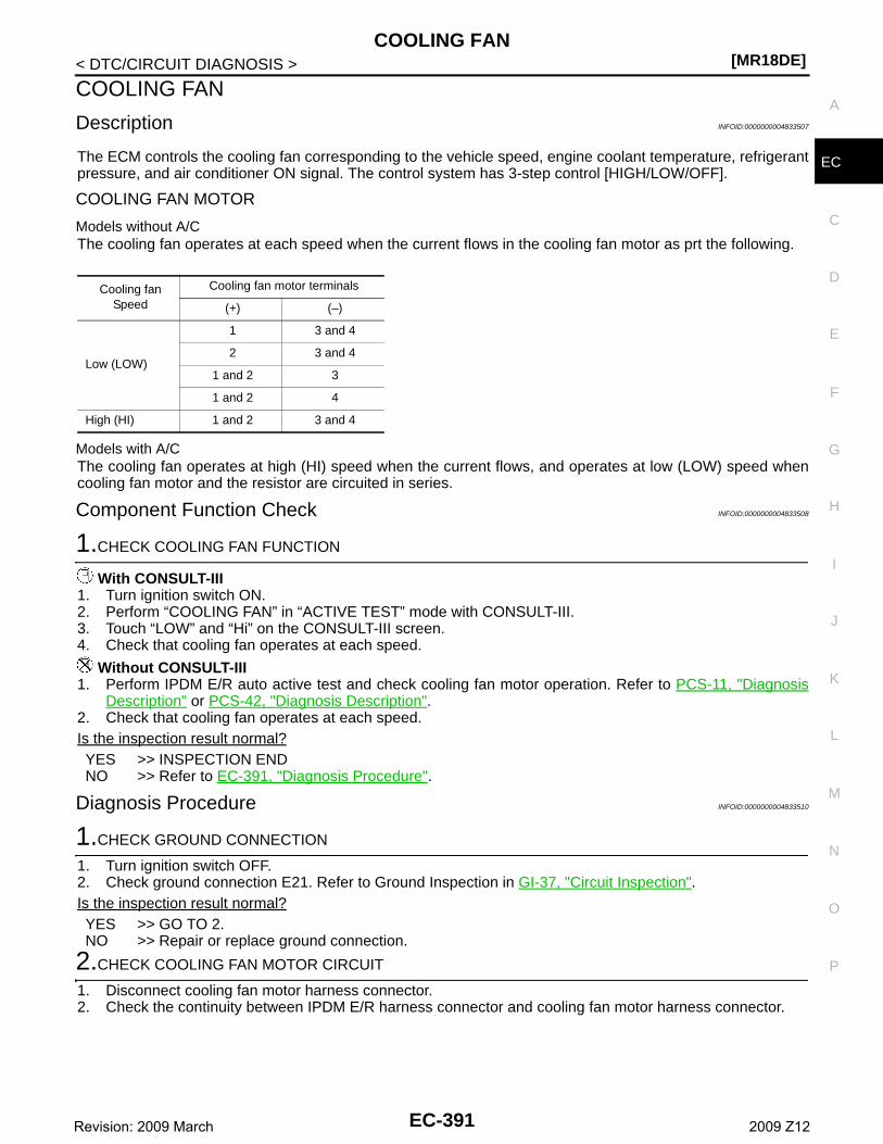
COOLING FAN[MR18DE]
C
D
E
F
G
H
I
J
K
L
M
A
C
N
P
O
< DTC/CIRCUIT DIAGNOSIS >
E
COOLING FAN
Description INFOID:0000000004833507
The ECM controls the cooling fan corresponding to the vehicle speed, engine coolant temperature, refrigerantpressure, and air conditioner ON signal. The control system has 3-step control [HIGH/LOW/OFF].
COOLING FAN MOTOR
Models without A/CThe cooling fan operates at each speed when the current flows in the cooling fan motor as prt the following.
Models with A/CThe cooling fan operates at high (HI) speed when the current flows, and operates at low (LOW) speed whencooling fan motor and the resistor are circuited in series.
Component Function Check INFOID:0000000004833508
1.CHECK COOLING FAN FUNCTION
With CONSULT-III1. Turn ignition switch ON.2. Perform “COOLING FAN” in “ACTIVE TEST” mode with CONSULT-III.3. Touch “LOW” and “Hi” on the CONSULT-III screen.4. Check that cooling fan operates at each speed.
Without CONSULT-III1. Perform IPDM E/R auto active test and check cooling fan motor operation. Refer to PCS-11, "Diagnosis
Description" or PCS-42, "Diagnosis Description".2. Check that cooling fan operates at each speed.Is the inspection result normal?YES >> INSPECTION ENDNO >> Refer to EC-391, "Diagnosis Procedure".
Diagnosis Procedure INFOID:0000000004833510
1.CHECK GROUND CONNECTION
1. Turn ignition switch OFF.2. Check ground connection E21. Refer to Ground Inspection in GI-37, "Circuit Inspection".Is the inspection result normal?YES >> GO TO 2.NO >> Repair or replace ground connection.
2.CHECK COOLING FAN MOTOR CIRCUIT
1. Disconnect cooling fan motor harness connector.2. Check the continuity between IPDM E/R harness connector and cooling fan motor harness connector.
Cooling fan Speed
Cooling fan motor terminals
(+) (–)
Low (LOW)
1 3 and 4
2 3 and 4
1 and 2 3
1 and 2 4
High (HI) 1 and 2 3 and 4
EC-391Revision: 2009 March 2009 Z12
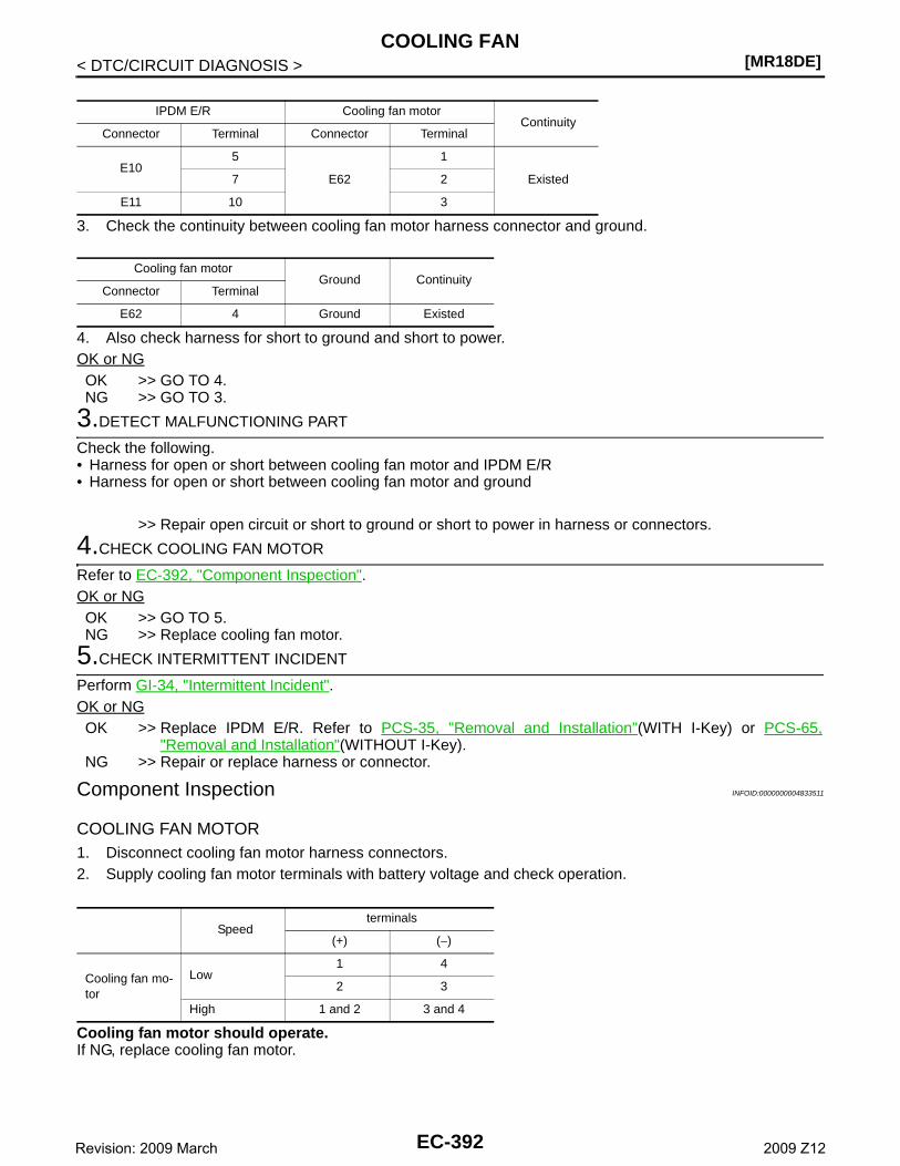
[MR18DE]COOLING FAN
< DTC/CIRCUIT DIAGNOSIS >
3. Check the continuity between cooling fan motor harness connector and ground.
4. Also check harness for short to ground and short to power.OK or NGOK >> GO TO 4.NG >> GO TO 3.
3.DETECT MALFUNCTIONING PART
Check the following.• Harness for open or short between cooling fan motor and IPDM E/R• Harness for open or short between cooling fan motor and ground
>> Repair open circuit or short to ground or short to power in harness or connectors.
4.CHECK COOLING FAN MOTOR
Refer to EC-392, "Component Inspection".OK or NGOK >> GO TO 5.NG >> Replace cooling fan motor.
5.CHECK INTERMITTENT INCIDENT
Perform GI-34, "Intermittent Incident".OK or NGOK >> Replace IPDM E/R. Refer to PCS-35, "Removal and Installation"(WITH I-Key) or PCS-65,
"Removal and Installation"(WITHOUT I-Key).NG >> Repair or replace harness or connector.
Component Inspection INFOID:0000000004833511
COOLING FAN MOTOR1. Disconnect cooling fan motor harness connectors.2. Supply cooling fan motor terminals with battery voltage and check operation.
Cooling fan motor should operate.If NG, replace cooling fan motor.
IPDM E/R Cooling fan motorContinuity
Connector Terminal Connector Terminal
E105
E62
1
Existed7 2
E11 10 3
Cooling fan motorGround Continuity
Connector Terminal
E62 4 Ground Existed
Speedterminals
(+) (−)
Cooling fan mo-tor
Low 1 4
2 3
High 1 and 2 3 and 4
EC-392Revision: 2009 March 2009 Z12
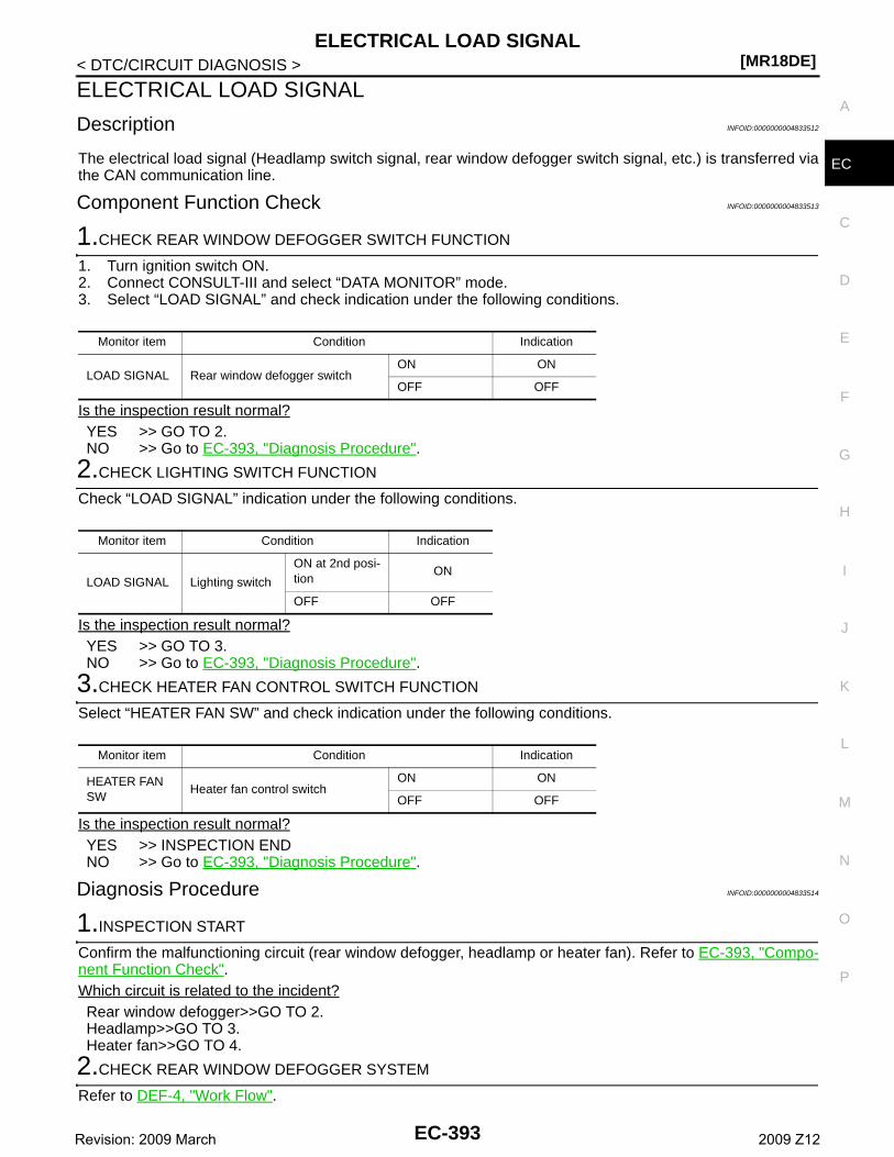
ELECTRICAL LOAD SIGNAL[MR18DE]
C
D
E
F
G
H
I
J
K
L
M
A
C
N
P
O
< DTC/CIRCUIT DIAGNOSIS >
E
ELECTRICAL LOAD SIGNAL
Description INFOID:0000000004833512
The electrical load signal (Headlamp switch signal, rear window defogger switch signal, etc.) is transferred viathe CAN communication line.
Component Function Check INFOID:0000000004833513
1.CHECK REAR WINDOW DEFOGGER SWITCH FUNCTION
1. Turn ignition switch ON.2. Connect CONSULT-III and select “DATA MONITOR” mode.3. Select “LOAD SIGNAL” and check indication under the following conditions.
Is the inspection result normal?YES >> GO TO 2.NO >> Go to EC-393, "Diagnosis Procedure".
2.CHECK LIGHTING SWITCH FUNCTION
Check “LOAD SIGNAL” indication under the following conditions.
Is the inspection result normal?YES >> GO TO 3.NO >> Go to EC-393, "Diagnosis Procedure".
3.CHECK HEATER FAN CONTROL SWITCH FUNCTION
Select “HEATER FAN SW” and check indication under the following conditions.
Is the inspection result normal?YES >> INSPECTION ENDNO >> Go to EC-393, "Diagnosis Procedure".
Diagnosis Procedure INFOID:0000000004833514
1.INSPECTION START
Confirm the malfunctioning circuit (rear window defogger, headlamp or heater fan). Refer to EC-393, "Compo-nent Function Check".Which circuit is related to the incident?Rear window defogger>>GO TO 2.Headlamp>>GO TO 3.Heater fan>>GO TO 4.
2.CHECK REAR WINDOW DEFOGGER SYSTEM
Refer to DEF-4, "Work Flow".
Monitor item Condition Indication
LOAD SIGNAL Rear window defogger switchON ON
OFF OFF
Monitor item Condition Indication
LOAD SIGNAL Lighting switch
ON at 2nd posi-tion
ON
OFF OFF
Monitor item Condition Indication
HEATER FAN SW
Heater fan control switchON ON
OFF OFF
EC-393Revision: 2009 March 2009 Z12
[MR18DE]ELECTRICAL LOAD SIGNAL
< DTC/CIRCUIT DIAGNOSIS >
>> INSPECTION END
3.CHECK HEADLAMP SYSTEM
Refer to EXL-5, "Work Flow".
>> INSPECTION END
4.CHECK HEATER FAN CONTROL SYSTEM
Refer to HA-3, "Work Flow".
>> INSPECTION END
EC-394Revision: 2009 March 2009 Z12
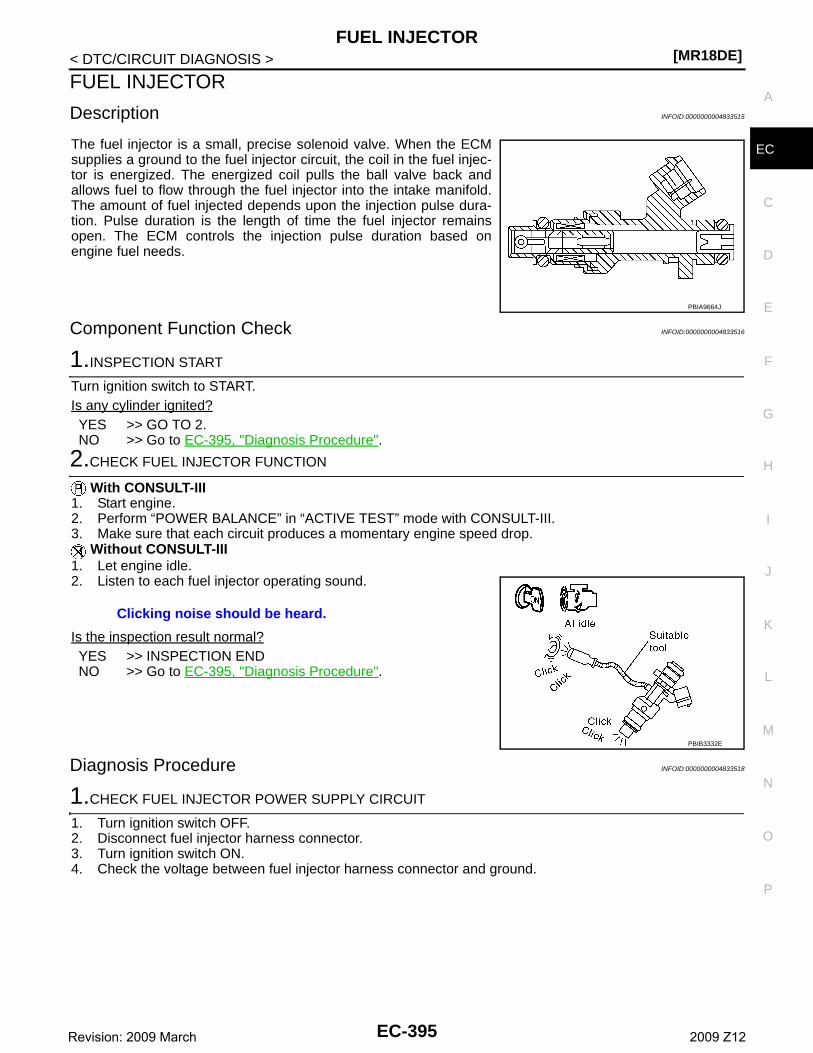
FUEL INJECTOR[MR18DE]
C
D
E
F
G
H
I
J
K
L
M
A
C
N
P
O
< DTC/CIRCUIT DIAGNOSIS >
E
FUEL INJECTOR
Description INFOID:0000000004833515
The fuel injector is a small, precise solenoid valve. When the ECMsupplies a ground to the fuel injector circuit, the coil in the fuel injec-tor is energized. The energized coil pulls the ball valve back andallows fuel to flow through the fuel injector into the intake manifold.The amount of fuel injected depends upon the injection pulse dura-tion. Pulse duration is the length of time the fuel injector remainsopen. The ECM controls the injection pulse duration based onengine fuel needs.
Component Function Check INFOID:0000000004833516
1.INSPECTION START
Turn ignition switch to START.Is any cylinder ignited?YES >> GO TO 2.NO >> Go to EC-395, "Diagnosis Procedure".
2.CHECK FUEL INJECTOR FUNCTION
With CONSULT-III1. Start engine.2. Perform “POWER BALANCE” in “ACTIVE TEST” mode with CONSULT-III.3. Make sure that each circuit produces a momentary engine speed drop.
Without CONSULT-III1. Let engine idle.2. Listen to each fuel injector operating sound.
Is the inspection result normal?YES >> INSPECTION ENDNO >> Go to EC-395, "Diagnosis Procedure".
Diagnosis Procedure INFOID:0000000004833518
1.CHECK FUEL INJECTOR POWER SUPPLY CIRCUIT
1. Turn ignition switch OFF.2. Disconnect fuel injector harness connector.3. Turn ignition switch ON.4. Check the voltage between fuel injector harness connector and ground.
PBIA9664J
Clicking noise should be heard.
PBIB3332E
EC-395Revision: 2009 March 2009 Z12
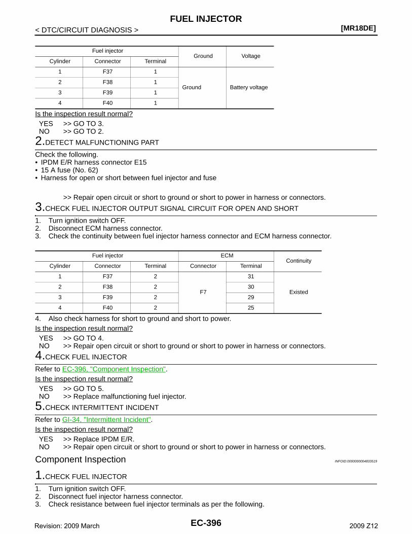
[MR18DE]FUEL INJECTOR
< DTC/CIRCUIT DIAGNOSIS >
Is the inspection result normal?YES >> GO TO 3.NO >> GO TO 2.
2.DETECT MALFUNCTIONING PART
Check the following.• IPDM E/R harness connector E15• 15 A fuse (No. 62)• Harness for open or short between fuel injector and fuse
>> Repair open circuit or short to ground or short to power in harness or connectors.
3.CHECK FUEL INJECTOR OUTPUT SIGNAL CIRCUIT FOR OPEN AND SHORT
1. Turn ignition switch OFF.2. Disconnect ECM harness connector.3. Check the continuity between fuel injector harness connector and ECM harness connector.
4. Also check harness for short to ground and short to power.Is the inspection result normal?YES >> GO TO 4.NO >> Repair open circuit or short to ground or short to power in harness or connectors.
4.CHECK FUEL INJECTOR
Refer to EC-396, "Component Inspection".Is the inspection result normal?YES >> GO TO 5.NO >> Replace malfunctioning fuel injector.
5.CHECK INTERMITTENT INCIDENT
Refer to GI-34, "Intermittent Incident".Is the inspection result normal?YES >> Replace IPDM E/R.NO >> Repair open circuit or short to ground or short to power in harness or connectors.
Component Inspection INFOID:0000000004833519
1.CHECK FUEL INJECTOR
1. Turn ignition switch OFF.2. Disconnect fuel injector harness connector.3. Check resistance between fuel injector terminals as per the following.
Fuel injectorGround Voltage
Cylinder Connector Terminal
1 F37 1
Ground Battery voltage2 F38 1
3 F39 1
4 F40 1
Fuel injector ECMContinuity
Cylinder Connector Terminal Connector Terminal
1 F37 2
F7
31
Existed2 F38 2 30
3 F39 2 29
4 F40 2 25
EC-396Revision: 2009 March 2009 Z12
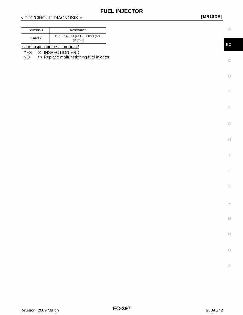
FUEL INJECTOR[MR18DE]
C
D
E
F
G
H
I
J
K
L
M
A
C
N
P
O
< DTC/CIRCUIT DIAGNOSIS >
EIs the inspection result normal?YES >> INSPECTION ENDNO >> Replace malfunctioning fuel injector.
Terminals Resistance
1 and 211.1 - 14.5 Ω [at 10 - 60°C (50 -
140°F)]
EC-397Revision: 2009 March 2009 Z12
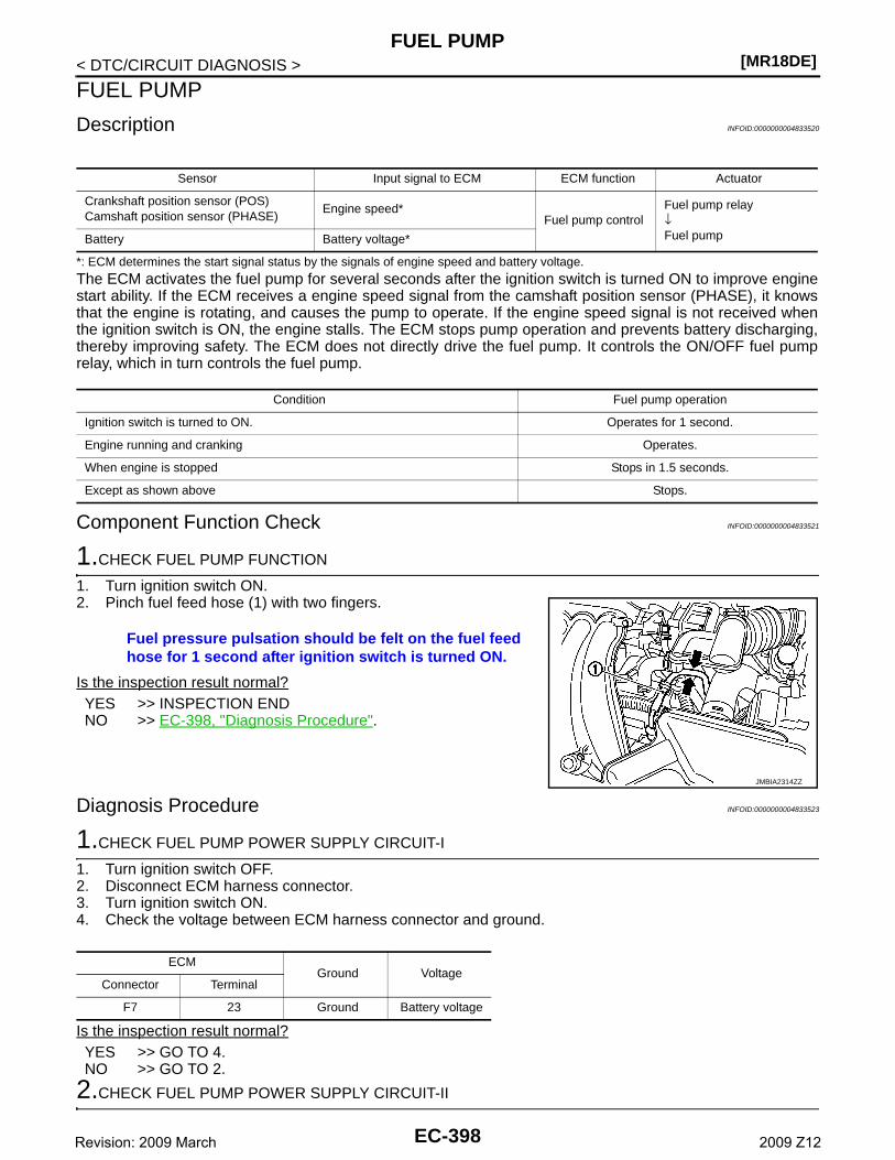
[MR18DE]FUEL PUMP
< DTC/CIRCUIT DIAGNOSIS >
FUEL PUMP
Description INFOID:0000000004833520
*: ECM determines the start signal status by the signals of engine speed and battery voltage.
The ECM activates the fuel pump for several seconds after the ignition switch is turned ON to improve enginestart ability. If the ECM receives a engine speed signal from the camshaft position sensor (PHASE), it knowsthat the engine is rotating, and causes the pump to operate. If the engine speed signal is not received whenthe ignition switch is ON, the engine stalls. The ECM stops pump operation and prevents battery discharging,thereby improving safety. The ECM does not directly drive the fuel pump. It controls the ON/OFF fuel pumprelay, which in turn controls the fuel pump.
Component Function Check INFOID:0000000004833521
1.CHECK FUEL PUMP FUNCTION
1. Turn ignition switch ON.2. Pinch fuel feed hose (1) with two fingers.
Is the inspection result normal?YES >> INSPECTION ENDNO >> EC-398, "Diagnosis Procedure".
Diagnosis Procedure INFOID:0000000004833523
1.CHECK FUEL PUMP POWER SUPPLY CIRCUIT-I
1. Turn ignition switch OFF.2. Disconnect ECM harness connector.3. Turn ignition switch ON.4. Check the voltage between ECM harness connector and ground.
Is the inspection result normal?YES >> GO TO 4.NO >> GO TO 2.
2.CHECK FUEL PUMP POWER SUPPLY CIRCUIT-II
Sensor Input signal to ECM ECM function Actuator
Crankshaft position sensor (POS)Camshaft position sensor (PHASE)
Engine speed*Fuel pump control
Fuel pump relay↓Fuel pumpBattery Battery voltage*
Condition Fuel pump operation
Ignition switch is turned to ON. Operates for 1 second.
Engine running and cranking Operates.
When engine is stopped Stops in 1.5 seconds.
Except as shown above Stops.
Fuel pressure pulsation should be felt on the fuel feed hose for 1 second after ignition switch is turned ON.
JMBIA2314ZZ
ECMGround Voltage
Connector Terminal
F7 23 Ground Battery voltage
EC-398Revision: 2009 March 2009 Z12
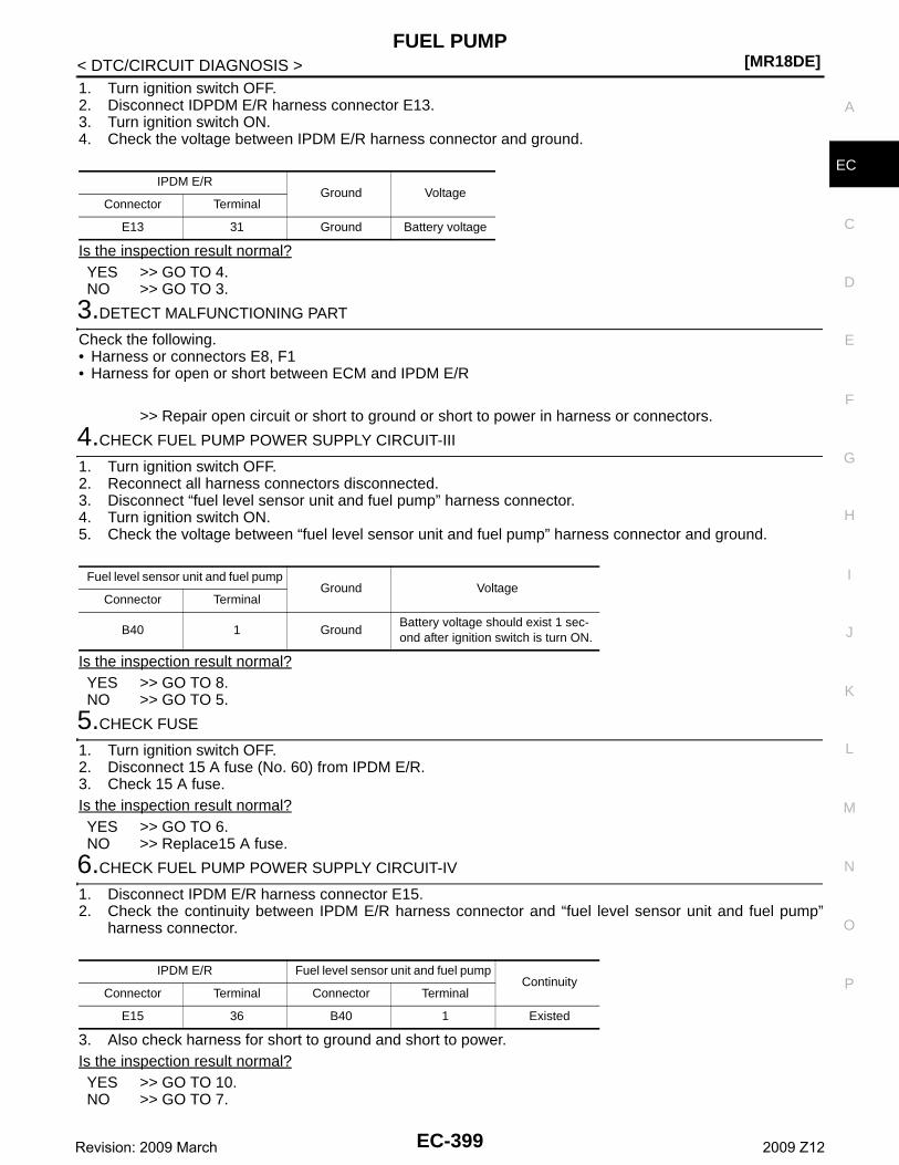
FUEL PUMP[MR18DE]
C
D
E
F
G
H
I
J
K
L
M
A
C
N
P
O
< DTC/CIRCUIT DIAGNOSIS >
E
1. Turn ignition switch OFF.2. Disconnect IDPDM E/R harness connector E13.3. Turn ignition switch ON.4. Check the voltage between IPDM E/R harness connector and ground.
Is the inspection result normal?YES >> GO TO 4.NO >> GO TO 3.
3.DETECT MALFUNCTIONING PART
Check the following.• Harness or connectors E8, F1• Harness for open or short between ECM and IPDM E/R
>> Repair open circuit or short to ground or short to power in harness or connectors.
4.CHECK FUEL PUMP POWER SUPPLY CIRCUIT-III
1. Turn ignition switch OFF.2. Reconnect all harness connectors disconnected.3. Disconnect “fuel level sensor unit and fuel pump” harness connector.4. Turn ignition switch ON.5. Check the voltage between “fuel level sensor unit and fuel pump” harness connector and ground.
Is the inspection result normal?YES >> GO TO 8.NO >> GO TO 5.
5.CHECK FUSE
1. Turn ignition switch OFF.2. Disconnect 15 A fuse (No. 60) from IPDM E/R.3. Check 15 A fuse.Is the inspection result normal?YES >> GO TO 6.NO >> Replace15 A fuse.
6.CHECK FUEL PUMP POWER SUPPLY CIRCUIT-IV
1. Disconnect IPDM E/R harness connector E15.2. Check the continuity between IPDM E/R harness connector and “fuel level sensor unit and fuel pump”
harness connector.
3. Also check harness for short to ground and short to power.Is the inspection result normal?YES >> GO TO 10.NO >> GO TO 7.
IPDM E/RGround Voltage
Connector Terminal
E13 31 Ground Battery voltage
Fuel level sensor unit and fuel pumpGround Voltage
Connector Terminal
B40 1 GroundBattery voltage should exist 1 sec-ond after ignition switch is turn ON.
IPDM E/R Fuel level sensor unit and fuel pumpContinuity
Connector Terminal Connector Terminal
E15 36 B40 1 Existed
EC-399Revision: 2009 March 2009 Z12
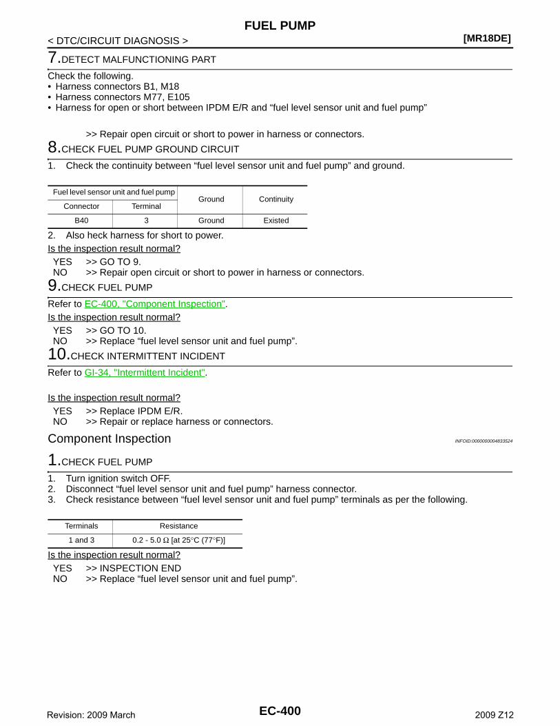
[MR18DE]FUEL PUMP
< DTC/CIRCUIT DIAGNOSIS >
7.DETECT MALFUNCTIONING PART
Check the following.• Harness connectors B1, M18• Harness connectors M77, E105• Harness for open or short between IPDM E/R and “fuel level sensor unit and fuel pump”
>> Repair open circuit or short to power in harness or connectors.
8.CHECK FUEL PUMP GROUND CIRCUIT
1. Check the continuity between “fuel level sensor unit and fuel pump” and ground.
2. Also heck harness for short to power. Is the inspection result normal?YES >> GO TO 9.NO >> Repair open circuit or short to power in harness or connectors.
9.CHECK FUEL PUMP
Refer to EC-400, "Component Inspection".Is the inspection result normal?YES >> GO TO 10.NO >> Replace “fuel level sensor unit and fuel pump”.
10.CHECK INTERMITTENT INCIDENT
Refer to GI-34, "Intermittent Incident".
Is the inspection result normal?YES >> Replace IPDM E/R.NO >> Repair or replace harness or connectors.
Component Inspection INFOID:0000000004833524
1.CHECK FUEL PUMP
1. Turn ignition switch OFF.2. Disconnect “fuel level sensor unit and fuel pump” harness connector.3. Check resistance between “fuel level sensor unit and fuel pump” terminals as per the following.
Is the inspection result normal?YES >> INSPECTION ENDNO >> Replace “fuel level sensor unit and fuel pump”.
Fuel level sensor unit and fuel pumpGround Continuity
Connector Terminal
B40 3 Ground Existed
Terminals Resistance
1 and 3 0.2 - 5.0 Ω [at 25°C (77°F)]
EC-400Revision: 2009 March 2009 Z12
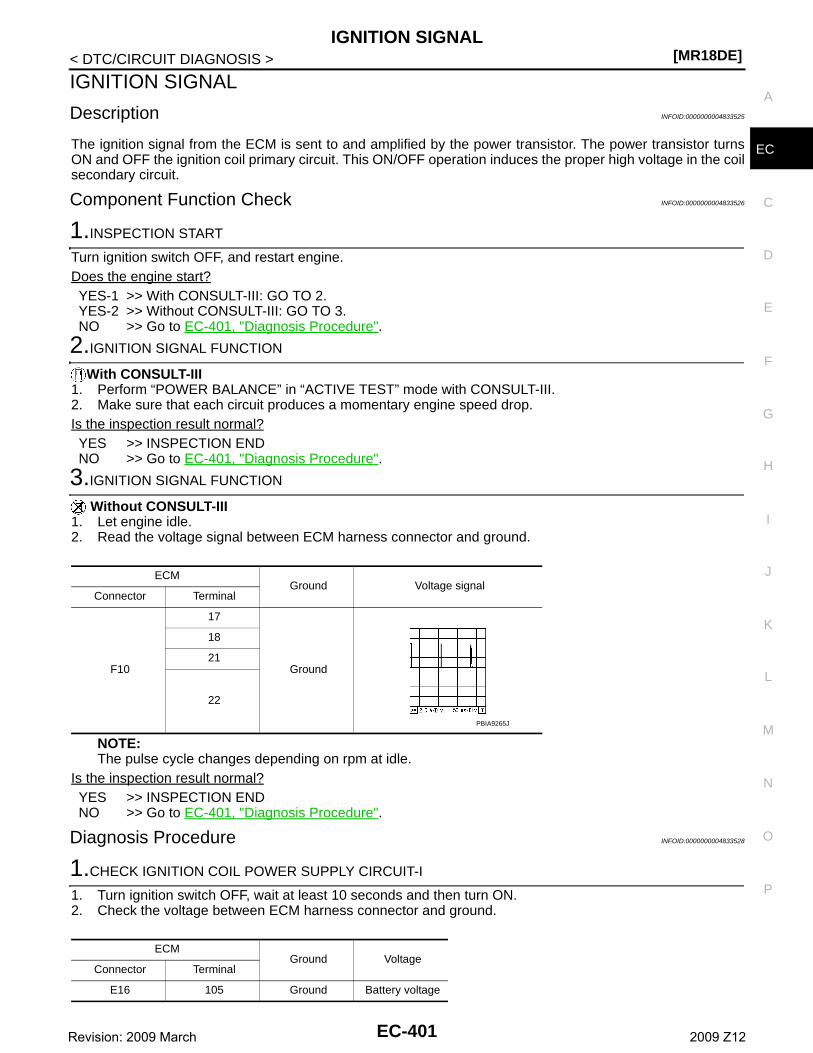
IGNITION SIGNAL[MR18DE]
C
D
E
F
G
H
I
J
K
L
M
A
C
N
P
O
< DTC/CIRCUIT DIAGNOSIS >
E
IGNITION SIGNAL
Description INFOID:0000000004833525
The ignition signal from the ECM is sent to and amplified by the power transistor. The power transistor turnsON and OFF the ignition coil primary circuit. This ON/OFF operation induces the proper high voltage in the coilsecondary circuit.
Component Function Check INFOID:0000000004833526
1.INSPECTION START
Turn ignition switch OFF, and restart engine.Does the engine start?YES-1 >> With CONSULT-III: GO TO 2.YES-2 >> Without CONSULT-III: GO TO 3.NO >> Go to EC-401, "Diagnosis Procedure".
2.IGNITION SIGNAL FUNCTION
With CONSULT-III1. Perform “POWER BALANCE” in “ACTIVE TEST” mode with CONSULT-III.2. Make sure that each circuit produces a momentary engine speed drop.Is the inspection result normal?YES >> INSPECTION ENDNO >> Go to EC-401, "Diagnosis Procedure".
3.IGNITION SIGNAL FUNCTION
Without CONSULT-III1. Let engine idle.2. Read the voltage signal between ECM harness connector and ground.
NOTE:The pulse cycle changes depending on rpm at idle.
Is the inspection result normal?YES >> INSPECTION ENDNO >> Go to EC-401, "Diagnosis Procedure".
Diagnosis Procedure INFOID:0000000004833528
1.CHECK IGNITION COIL POWER SUPPLY CIRCUIT-I
1. Turn ignition switch OFF, wait at least 10 seconds and then turn ON.2. Check the voltage between ECM harness connector and ground.
ECMGround Voltage signal
Connector Terminal
F10
17
Ground
18
21
22
PBIA9265J
ECMGround Voltage
Connector Terminal
E16 105 Ground Battery voltage
EC-401Revision: 2009 March 2009 Z12
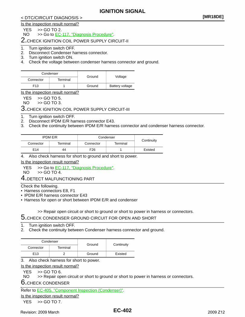
[MR18DE]IGNITION SIGNAL
< DTC/CIRCUIT DIAGNOSIS >Is the inspection result normal?YES >> GO TO 2.NO >> Go to EC-117, "Diagnosis Procedure".
2.CHECK IGNITION COIL POWER SUPPLY CIRCUIT-II
1. Turn ignition switch OFF.2. Disconnect Condenser harness connector.3. Turn ignition switch ON.4. Check the voltage between condenser harness connector and ground.
Is the inspection result normal?YES >> GO TO 5.NO >> GO TO 3.
3.CHECK IGNITION COIL POWER SUPPLY CIRCUIT-III
1. Turn ignition switch OFF.2. Disconnect IPDM E/R harness connector E43.3. Check the continuity between IPDM E/R harness connector and condenser harness connector.
4. Also check harness for short to ground and short to power.Is the inspection result normal?YES >> Go to EC-117, "Diagnosis Procedure".NO >> GO TO 4.
4.DETECT MALFUNCTIONING PART
Check the following.• Harness connectors E8, F1• IPDM E/R harness connector E43• Harness for open or short between IPDM E/R and condenser
>> Repair open circuit or short to ground or short to power in harness or connectors.
5.CHECK CONDENSER GROUND CIRCUIT FOR OPEN AND SHORT
1. Turn ignition switch OFF.2. Check the continuity between Condenser harness connector and ground.
3. Also check harness for short to power.Is the inspection result normal?YES >> GO TO 6.NO >> Repair open circuit or short to ground or short to power in harness or connectors.
6.CHECK CONDENSER
Refer to EC-405, "Component Inspection (Condenser)".Is the inspection result normal?YES >> GO TO 7.
CondenserGround Voltage
Connector Terminal
F13 1 Ground Battery voltage
IPDM E/R CondenserContinuity
Connector Terminal Connector Terminal
E14 44 F26 1 Existed
CondenserGround Continuity
Connector Terminal
E13 2 Ground Existed
EC-402Revision: 2009 March 2009 Z12
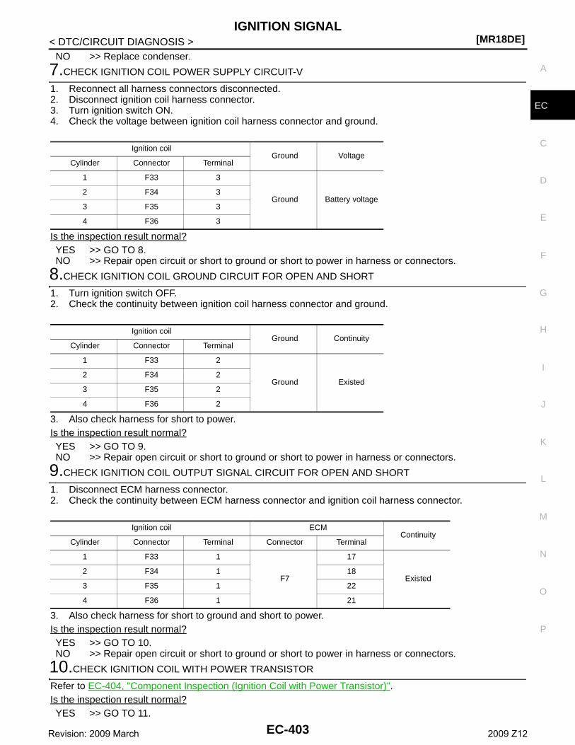
IGNITION SIGNAL[MR18DE]
C
D
E
F
G
H
I
J
K
L
M
A
C
N
P
O
< DTC/CIRCUIT DIAGNOSIS >
E
NO >> Replace condenser.
7.CHECK IGNITION COIL POWER SUPPLY CIRCUIT-V
1. Reconnect all harness connectors disconnected.2. Disconnect ignition coil harness connector.3. Turn ignition switch ON.4. Check the voltage between ignition coil harness connector and ground.
Is the inspection result normal?YES >> GO TO 8.NO >> Repair open circuit or short to ground or short to power in harness or connectors.
8.CHECK IGNITION COIL GROUND CIRCUIT FOR OPEN AND SHORT
1. Turn ignition switch OFF.2. Check the continuity between ignition coil harness connector and ground.
3. Also check harness for short to power.Is the inspection result normal?YES >> GO TO 9.NO >> Repair open circuit or short to ground or short to power in harness or connectors.
9.CHECK IGNITION COIL OUTPUT SIGNAL CIRCUIT FOR OPEN AND SHORT
1. Disconnect ECM harness connector.2. Check the continuity between ECM harness connector and ignition coil harness connector.
3. Also check harness for short to ground and short to power.Is the inspection result normal?YES >> GO TO 10.NO >> Repair open circuit or short to ground or short to power in harness or connectors.
10.CHECK IGNITION COIL WITH POWER TRANSISTOR
Refer to EC-404, "Component Inspection (Ignition Coil with Power Transistor)".Is the inspection result normal?YES >> GO TO 11.
Ignition coilGround Voltage
Cylinder Connector Terminal
1 F33 3
Ground Battery voltage2 F34 3
3 F35 3
4 F36 3
Ignition coilGround Continuity
Cylinder Connector Terminal
1 F33 2
Ground Existed2 F34 2
3 F35 2
4 F36 2
Ignition coil ECMContinuity
Cylinder Connector Terminal Connector Terminal
1 F33 1
F7
17
Existed2 F34 1 18
3 F35 1 22
4 F36 1 21
EC-403Revision: 2009 March 2009 Z12
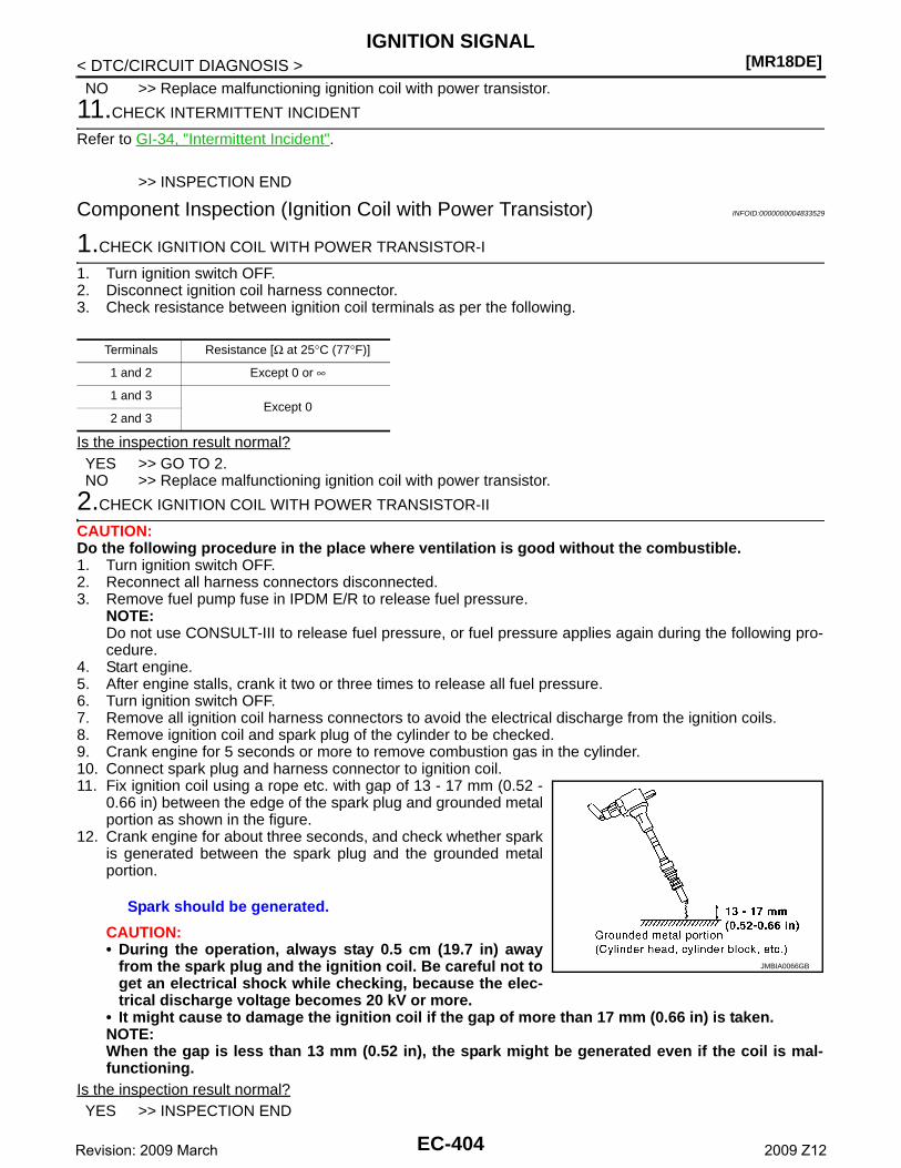
[MR18DE]IGNITION SIGNAL
< DTC/CIRCUIT DIAGNOSIS >NO >> Replace malfunctioning ignition coil with power transistor.
11.CHECK INTERMITTENT INCIDENT
Refer to GI-34, "Intermittent Incident".
>> INSPECTION END
Component Inspection (Ignition Coil with Power Transistor) INFOID:0000000004833529
1.CHECK IGNITION COIL WITH POWER TRANSISTOR-I
1. Turn ignition switch OFF.2. Disconnect ignition coil harness connector.3. Check resistance between ignition coil terminals as per the following.
Is the inspection result normal?YES >> GO TO 2.NO >> Replace malfunctioning ignition coil with power transistor.
2.CHECK IGNITION COIL WITH POWER TRANSISTOR-II
CAUTION:Do the following procedure in the place where ventilation is good without the combustible.1. Turn ignition switch OFF.2. Reconnect all harness connectors disconnected.3. Remove fuel pump fuse in IPDM E/R to release fuel pressure.
NOTE:Do not use CONSULT-III to release fuel pressure, or fuel pressure applies again during the following pro-cedure.
4. Start engine.5. After engine stalls, crank it two or three times to release all fuel pressure.6. Turn ignition switch OFF.7. Remove all ignition coil harness connectors to avoid the electrical discharge from the ignition coils.8. Remove ignition coil and spark plug of the cylinder to be checked.9. Crank engine for 5 seconds or more to remove combustion gas in the cylinder.10. Connect spark plug and harness connector to ignition coil.11. Fix ignition coil using a rope etc. with gap of 13 - 17 mm (0.52 -
0.66 in) between the edge of the spark plug and grounded metalportion as shown in the figure.
12. Crank engine for about three seconds, and check whether sparkis generated between the spark plug and the grounded metalportion.
CAUTION:• During the operation, always stay 0.5 cm (19.7 in) away
from the spark plug and the ignition coil. Be careful not toget an electrical shock while checking, because the elec-trical discharge voltage becomes 20 kV or more.
• It might cause to damage the ignition coil if the gap of more than 17 mm (0.66 in) is taken.NOTE:When the gap is less than 13 mm (0.52 in), the spark might be generated even if the coil is mal-functioning.
Is the inspection result normal?YES >> INSPECTION END
Terminals Resistance [Ω at 25°C (77°F)]
1 and 2 Except 0 or ∞
1 and 3Except 0
2 and 3
Spark should be generated.
JMBIA0066GB
EC-404Revision: 2009 March 2009 Z12
IGNITION SIGNAL[MR18DE]
C
D
E
F
G
H
I
J
K
L
M
A
C
N
P
O
< DTC/CIRCUIT DIAGNOSIS >
E
NO >> Replace malfunctioning ignition coil with power transistor.
Component Inspection (Condenser) INFOID:0000000004833530
1.CHECK CONDENSER
1. Turn ignition switch OFF.2. Disconnect condenser harness connector.3. Check resistance between condenser terminals as per the following.
Is the inspection result normal?YES >> INSPECTION ENDNO >> Replace Condenser.
Terminals Resistance
1 and 2 Above 1 MΩ [at 25°C (77°F)]
EC-405Revision: 2009 March 2009 Z12
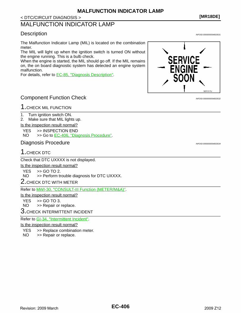
[MR18DE]MALFUNCTION INDICATOR LAMP
< DTC/CIRCUIT DIAGNOSIS >
MALFUNCTION INDICATOR LAMP
Description INFOID:0000000004833531
The Malfunction Indicator Lamp (MIL) is located on the combinationmeter.The MIL will light up when the ignition switch is turned ON withoutthe engine running. This is a bulb check.When the engine is started, the MIL should go off. If the MIL remainson, the on board diagnostic system has detected an engine systemmalfunction.For details, refer to EC-85, "Diagnosis Description".
Component Function Check INFOID:0000000004833532
1.CHECK MIL FUNCTION
1. Turn ignition switch ON.2. Make sure that MIL lights up.Is the inspection result normal?YES >> INSPECTION ENDNO >> Go to EC-406, "Diagnosis Procedure".
Diagnosis Procedure INFOID:0000000004833534
1.CHECK DTC
Check that DTC UXXXX is not displayed.Is the inspection result normal?YES >> GO TO 2.NO >> Perform trouble diagnosis for DTC UXXXX.
2.CHECK DTC WITH METER
Refer to MWI-30, "CONSULT-III Function (METER/M&A)".Is the inspection result normal?YES >> GO TO 3.NO >> Repair or replace.
3.CHECK INTERMITTENT INCIDENT
Refer to GI-34, "Intermittent Incident".Is the inspection result normal?YES >> Replace combination meter.NO >> Repair or replace.
SEF217U
EC-406Revision: 2009 March 2009 Z12
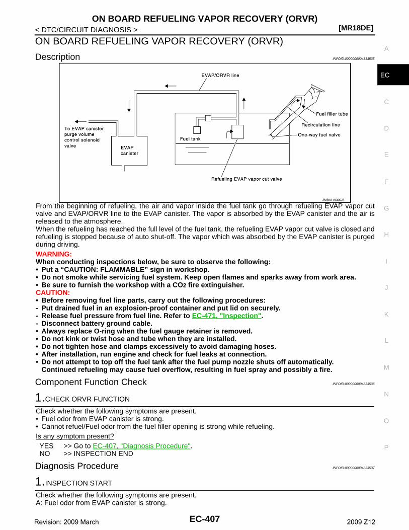
ON BOARD REFUELING VAPOR RECOVERY (ORVR)[MR18DE]
C
D
E
F
G
H
I
J
K
L
M
A
C
N
P
O
< DTC/CIRCUIT DIAGNOSIS >
E
ON BOARD REFUELING VAPOR RECOVERY (ORVR)
Description INFOID:0000000004833535
From the beginning of refueling, the air and vapor inside the fuel tank go through refueling EVAP vapor cutvalve and EVAP/ORVR line to the EVAP canister. The vapor is absorbed by the EVAP canister and the air isreleased to the atmosphere.When the refueling has reached the full level of the fuel tank, the refueling EVAP vapor cut valve is closed andrefueling is stopped because of auto shut-off. The vapor which was absorbed by the EVAP canister is purgedduring driving.WARNING:When conducting inspections below, be sure to observe the following:• Put a “CAUTION: FLAMMABLE” sign in workshop.• Do not smoke while servicing fuel system. Keep open flames and sparks away from work area.• Be sure to furnish the workshop with a CO2 fire extinguisher.CAUTION:• Before removing fuel line parts, carry out the following procedures:- Put drained fuel in an explosion-proof container and put lid on securely.- Release fuel pressure from fuel line. Refer to EC-471, "Inspection".- Disconnect battery ground cable.• Always replace O-ring when the fuel gauge retainer is removed.• Do not kink or twist hose and tube when they are installed.• Do not tighten hose and clamps excessively to avoid damaging hoses.• After installation, run engine and check for fuel leaks at connection.• Do not attempt to top off the fuel tank after the fuel pump nozzle shuts off automatically.
Continued refueling may cause fuel overflow, resulting in fuel spray and possibly a fire.
Component Function Check INFOID:0000000004833536
1.CHECK ORVR FUNCTION
Check whether the following symptoms are present.• Fuel odor from EVAP canister is strong.• Cannot refuel/Fuel odor from the fuel filler opening is strong while refueling.Is any symptom present?YES >> Go to EC-407, "Diagnosis Procedure".NO >> INSPECTION END
Diagnosis Procedure INFOID:0000000004833537
1.INSPECTION START
Check whether the following symptoms are present.A: Fuel odor from EVAP canister is strong.
JMBIA1930GB
EC-407Revision: 2009 March 2009 Z12
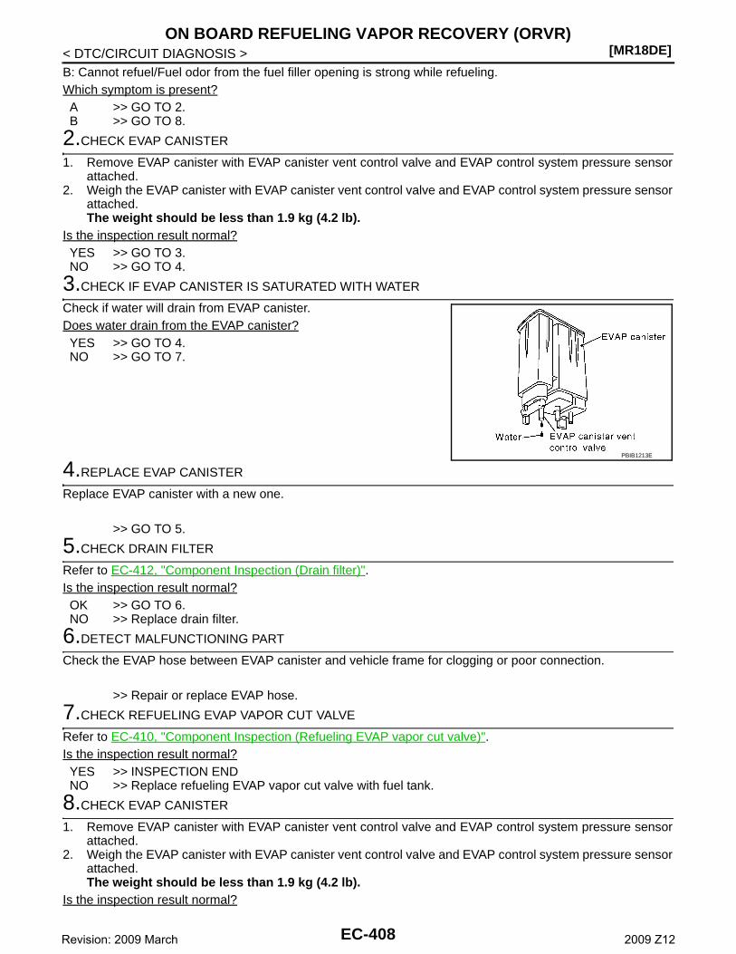
[MR18DE]ON BOARD REFUELING VAPOR RECOVERY (ORVR)
< DTC/CIRCUIT DIAGNOSIS >B: Cannot refuel/Fuel odor from the fuel filler opening is strong while refueling.Which symptom is present?A >> GO TO 2.B >> GO TO 8.
2.CHECK EVAP CANISTER
1. Remove EVAP canister with EVAP canister vent control valve and EVAP control system pressure sensorattached.
2. Weigh the EVAP canister with EVAP canister vent control valve and EVAP control system pressure sensorattached.The weight should be less than 1.9 kg (4.2 lb).
Is the inspection result normal?YES >> GO TO 3.NO >> GO TO 4.
3.CHECK IF EVAP CANISTER IS SATURATED WITH WATER
Check if water will drain from EVAP canister.Does water drain from the EVAP canister?YES >> GO TO 4.NO >> GO TO 7.
4.REPLACE EVAP CANISTER
Replace EVAP canister with a new one.
>> GO TO 5.
5.CHECK DRAIN FILTER
Refer to EC-412, "Component Inspection (Drain filter)".Is the inspection result normal?OK >> GO TO 6.NO >> Replace drain filter.
6.DETECT MALFUNCTIONING PART
Check the EVAP hose between EVAP canister and vehicle frame for clogging or poor connection.
>> Repair or replace EVAP hose.
7.CHECK REFUELING EVAP VAPOR CUT VALVE
Refer to EC-410, "Component Inspection (Refueling EVAP vapor cut valve)".Is the inspection result normal?YES >> INSPECTION ENDNO >> Replace refueling EVAP vapor cut valve with fuel tank.
8.CHECK EVAP CANISTER
1. Remove EVAP canister with EVAP canister vent control valve and EVAP control system pressure sensorattached.
2. Weigh the EVAP canister with EVAP canister vent control valve and EVAP control system pressure sensorattached.The weight should be less than 1.9 kg (4.2 lb).
Is the inspection result normal?
PBIB1213E
EC-408Revision: 2009 March 2009 Z12
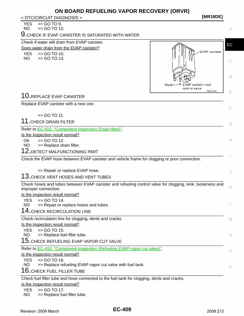
ON BOARD REFUELING VAPOR RECOVERY (ORVR)[MR18DE]
C
D
E
F
G
H
I
J
K
L
M
A
C
N
P
O
< DTC/CIRCUIT DIAGNOSIS >
E
YES >> GO TO 9.NO >> GO TO 10.
9.CHECK IF EVAP CANISTER IS SATURATED WITH WATER
Check if water will drain from EVAP canister.Does water drain from the EVAP canister?YES >> GO TO 10.NO >> GO TO 13.
10.REPLACE EVAP CANISTER
Replace EVAP canister with a new one.
>> GO TO 11.
11.CHECK DRAIN FILTER
Refer to EC-412, "Component Inspection (Drain filter)".Is the inspection result normal?OK >> GO TO 12.NO >> Replace drain filter.
12.DETECT MALFUNCTIONING PART
Check the EVAP hose between EVAP canister and vehicle frame for clogging or poor connection.
>> Repair or replace EVAP hose.
13.CHECK VENT HOSES AND VENT TUBES
Check hoses and tubes between EVAP canister and refueling control valve for clogging, kink, looseness andimproper connection.Is the inspection result normal?YES >> GO TO 14.NO >> Repair or replace hoses and tubes.
14.CHECK RECIRCULATION LINE
Check recirculation line for clogging, dents and cracks. Is the inspection result normal?YES >> GO TO 15.NO >> Replace fuel filler tube.
15.CHECK REFUELING EVAP VAPOR CUT VALVE
Refer to EC-410, "Component Inspection (Refueling EVAP vapor cut valve)".Is the inspection result normal?YES >> GO TO 16.NO >> Replace refueling EVAP vapor cut valve with fuel tank.
16.CHECK FUEL FILLER TUBE
Check fuel filler tube and hose connected to the fuel tank for clogging, dents and cracks.Is the inspection result normal?YES >> GO TO 17.NO >> Replace fuel filler tube.
PBIB1213E
EC-409Revision: 2009 March 2009 Z12
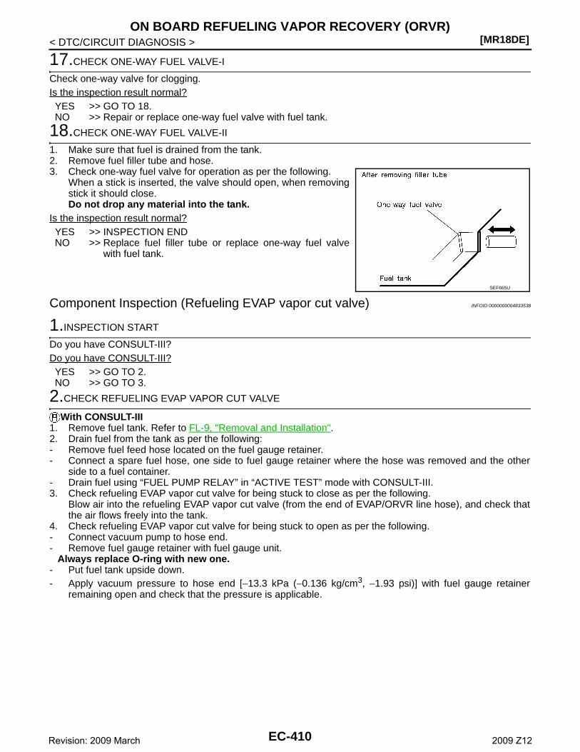
[MR18DE]ON BOARD REFUELING VAPOR RECOVERY (ORVR)
< DTC/CIRCUIT DIAGNOSIS >
17.CHECK ONE-WAY FUEL VALVE-I
Check one-way valve for clogging.Is the inspection result normal?YES >> GO TO 18.NO >> Repair or replace one-way fuel valve with fuel tank.
18.CHECK ONE-WAY FUEL VALVE-II
1. Make sure that fuel is drained from the tank.2. Remove fuel filler tube and hose.3. Check one-way fuel valve for operation as per the following.
When a stick is inserted, the valve should open, when removingstick it should close.Do not drop any material into the tank.
Is the inspection result normal?YES >> INSPECTION ENDNO >> Replace fuel filler tube or replace one-way fuel valve
with fuel tank.
Component Inspection (Refueling EVAP vapor cut valve) INFOID:0000000004833538
1.INSPECTION START
Do you have CONSULT-III?Do you have CONSULT-III?YES >> GO TO 2.NO >> GO TO 3.
2.CHECK REFUELING EVAP VAPOR CUT VALVE
With CONSULT-III1. Remove fuel tank. Refer to FL-9, "Removal and Installation".2. Drain fuel from the tank as per the following:- Remove fuel feed hose located on the fuel gauge retainer.- Connect a spare fuel hose, one side to fuel gauge retainer where the hose was removed and the other
side to a fuel container.- Drain fuel using “FUEL PUMP RELAY” in “ACTIVE TEST” mode with CONSULT-III.3. Check refueling EVAP vapor cut valve for being stuck to close as per the following.
Blow air into the refueling EVAP vapor cut valve (from the end of EVAP/ORVR line hose), and check thatthe air flows freely into the tank.
4. Check refueling EVAP vapor cut valve for being stuck to open as per the following.- Connect vacuum pump to hose end.- Remove fuel gauge retainer with fuel gauge unit.
Always replace O-ring with new one.- Put fuel tank upside down.- Apply vacuum pressure to hose end [−13.3 kPa (−0.136 kg/cm3, −1.93 psi)] with fuel gauge retainer
remaining open and check that the pressure is applicable.
SEF665U
EC-410Revision: 2009 March 2009 Z12
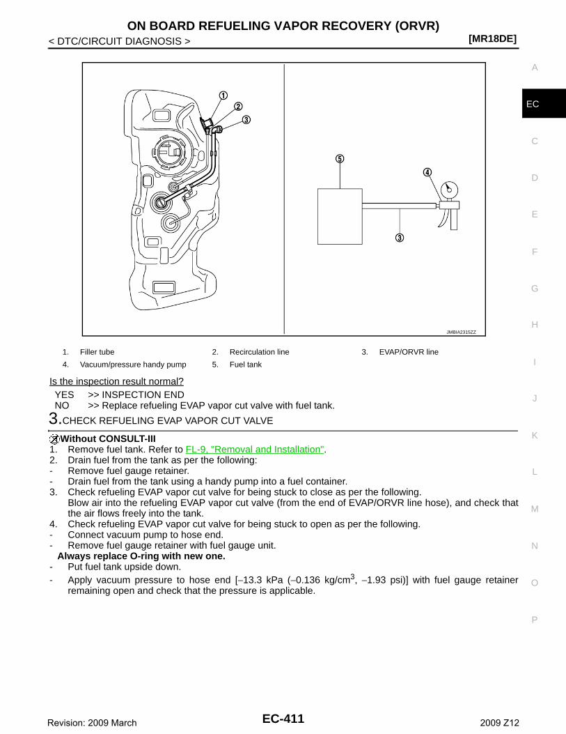
ON BOARD REFUELING VAPOR RECOVERY (ORVR)[MR18DE]
C
D
E
F
G
H
I
J
K
L
M
A
C
N
P
O
< DTC/CIRCUIT DIAGNOSIS >
E
Is the inspection result normal?YES >> INSPECTION ENDNO >> Replace refueling EVAP vapor cut valve with fuel tank.
3.CHECK REFUELING EVAP VAPOR CUT VALVE
Without CONSULT-III1. Remove fuel tank. Refer to FL-9, "Removal and Installation".2. Drain fuel from the tank as per the following:- Remove fuel gauge retainer.- Drain fuel from the tank using a handy pump into a fuel container.3. Check refueling EVAP vapor cut valve for being stuck to close as per the following.
Blow air into the refueling EVAP vapor cut valve (from the end of EVAP/ORVR line hose), and check thatthe air flows freely into the tank.
4. Check refueling EVAP vapor cut valve for being stuck to open as per the following.- Connect vacuum pump to hose end.- Remove fuel gauge retainer with fuel gauge unit.
Always replace O-ring with new one.- Put fuel tank upside down.- Apply vacuum pressure to hose end [−13.3 kPa (−0.136 kg/cm3, −1.93 psi)] with fuel gauge retainer
remaining open and check that the pressure is applicable.
1. Filler tube 2. Recirculation line 3. EVAP/ORVR line
4. Vacuum/pressure handy pump 5. Fuel tank
JMBIA2315ZZ
EC-411Revision: 2009 March 2009 Z12
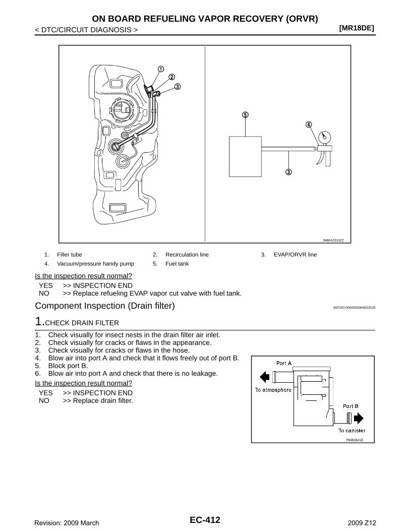
[MR18DE]ON BOARD REFUELING VAPOR RECOVERY (ORVR)
< DTC/CIRCUIT DIAGNOSIS >
Is the inspection result normal?YES >> INSPECTION ENDNO >> Replace refueling EVAP vapor cut valve with fuel tank.
Component Inspection (Drain filter) INFOID:0000000004833539
1.CHECK DRAIN FILTER
1. Check visually for insect nests in the drain filter air inlet.2. Check visually for cracks or flaws in the appearance.3. Check visually for cracks or flaws in the hose.4. Blow air into port A and check that it flows freely out of port B.5. Block port B.6. Blow air into port A and check that there is no leakage.Is the inspection result normal?YES >> INSPECTION ENDNO >> Replace drain filter.
1. Filler tube 2. Recirculation line 3. EVAP/ORVR line
4. Vacuum/pressure handy pump 5. Fuel tank
JMBIA2315ZZ
PBIB3641E
EC-412Revision: 2009 March 2009 Z12
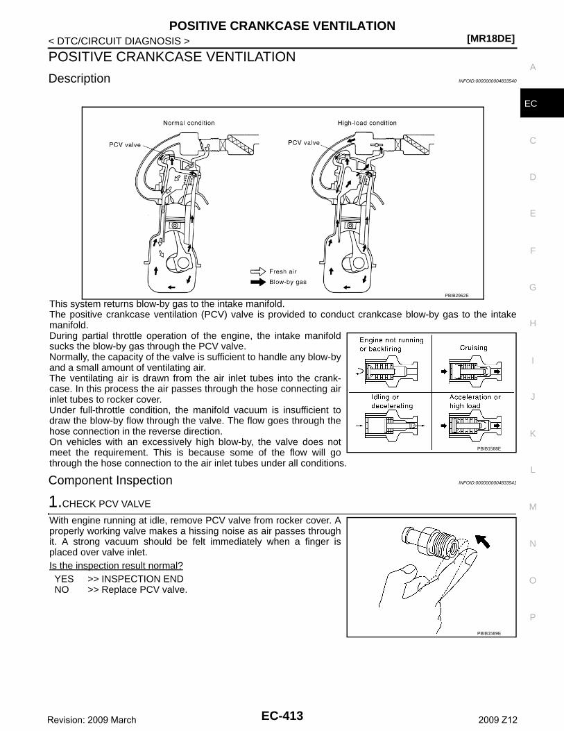
POSITIVE CRANKCASE VENTILATION[MR18DE]
C
D
E
F
G
H
I
J
K
L
M
A
C
N
P
O
< DTC/CIRCUIT DIAGNOSIS >
E
POSITIVE CRANKCASE VENTILATION
Description INFOID:0000000004833540
This system returns blow-by gas to the intake manifold.The positive crankcase ventilation (PCV) valve is provided to conduct crankcase blow-by gas to the intakemanifold.During partial throttle operation of the engine, the intake manifoldsucks the blow-by gas through the PCV valve.Normally, the capacity of the valve is sufficient to handle any blow-byand a small amount of ventilating air.The ventilating air is drawn from the air inlet tubes into the crank-case. In this process the air passes through the hose connecting airinlet tubes to rocker cover.Under full-throttle condition, the manifold vacuum is insufficient todraw the blow-by flow through the valve. The flow goes through thehose connection in the reverse direction.On vehicles with an excessively high blow-by, the valve does notmeet the requirement. This is because some of the flow will gothrough the hose connection to the air inlet tubes under all conditions.
Component Inspection INFOID:0000000004833541
1.CHECK PCV VALVE
With engine running at idle, remove PCV valve from rocker cover. Aproperly working valve makes a hissing noise as air passes throughit. A strong vacuum should be felt immediately when a finger isplaced over valve inlet.Is the inspection result normal?YES >> INSPECTION ENDNO >> Replace PCV valve.
PBIB2962E
PBIB1588E
PBIB1589E
EC-413Revision: 2009 March 2009 Z12
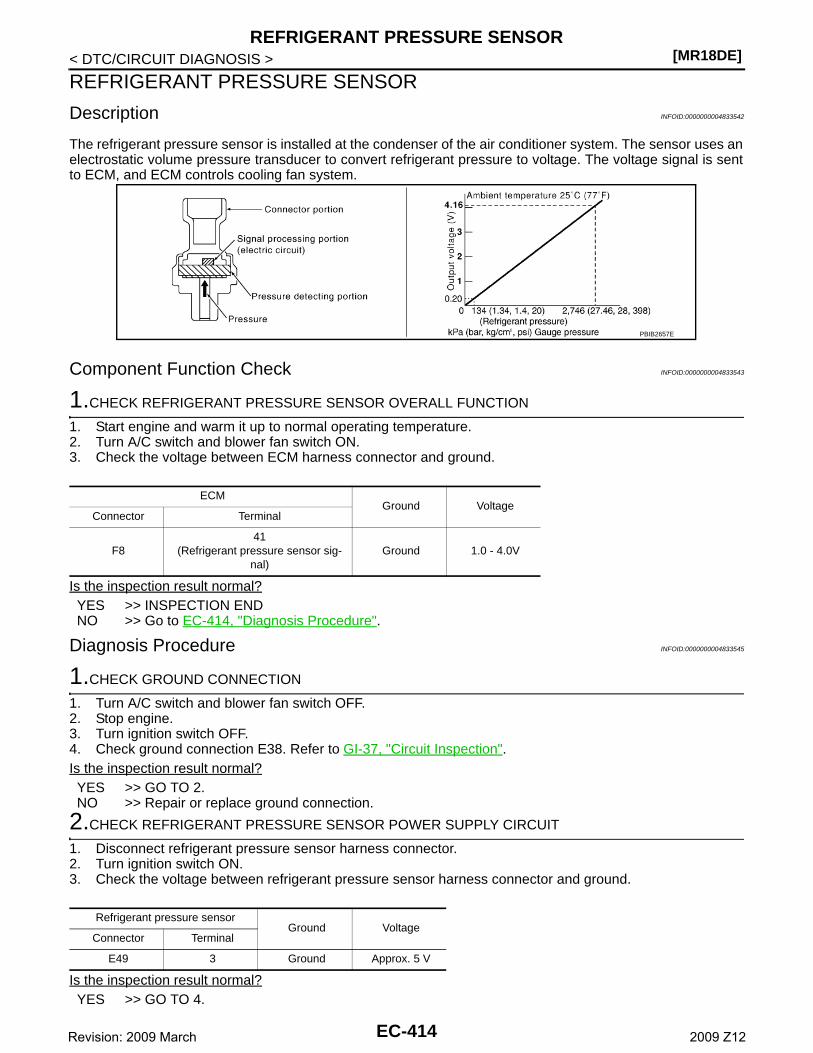
[MR18DE]REFRIGERANT PRESSURE SENSOR
< DTC/CIRCUIT DIAGNOSIS >
REFRIGERANT PRESSURE SENSOR
Description INFOID:0000000004833542
The refrigerant pressure sensor is installed at the condenser of the air conditioner system. The sensor uses anelectrostatic volume pressure transducer to convert refrigerant pressure to voltage. The voltage signal is sentto ECM, and ECM controls cooling fan system.
Component Function Check INFOID:0000000004833543
1.CHECK REFRIGERANT PRESSURE SENSOR OVERALL FUNCTION
1. Start engine and warm it up to normal operating temperature.2. Turn A/C switch and blower fan switch ON.3. Check the voltage between ECM harness connector and ground.
Is the inspection result normal?YES >> INSPECTION ENDNO >> Go to EC-414, "Diagnosis Procedure".
Diagnosis Procedure INFOID:0000000004833545
1.CHECK GROUND CONNECTION
1. Turn A/C switch and blower fan switch OFF.2. Stop engine.3. Turn ignition switch OFF.4. Check ground connection E38. Refer to GI-37, "Circuit Inspection". Is the inspection result normal?YES >> GO TO 2.NO >> Repair or replace ground connection.
2.CHECK REFRIGERANT PRESSURE SENSOR POWER SUPPLY CIRCUIT
1. Disconnect refrigerant pressure sensor harness connector.2. Turn ignition switch ON.3. Check the voltage between refrigerant pressure sensor harness connector and ground.
Is the inspection result normal?YES >> GO TO 4.
PBIB2657E
ECMGround Voltage
Connector Terminal
F841
(Refrigerant pressure sensor sig-nal)
Ground 1.0 - 4.0V
Refrigerant pressure sensorGround Voltage
Connector Terminal
E49 3 Ground Approx. 5 V
EC-414Revision: 2009 March 2009 Z12
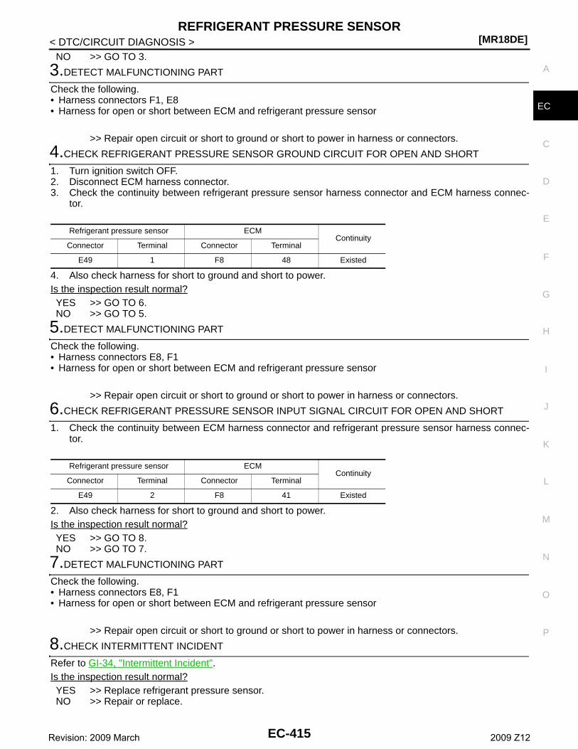
REFRIGERANT PRESSURE SENSOR[MR18DE]
C
D
E
F
G
H
I
J
K
L
M
A
C
N
P
O
< DTC/CIRCUIT DIAGNOSIS >
E
NO >> GO TO 3.
3.DETECT MALFUNCTIONING PART
Check the following.• Harness connectors F1, E8• Harness for open or short between ECM and refrigerant pressure sensor
>> Repair open circuit or short to ground or short to power in harness or connectors.
4.CHECK REFRIGERANT PRESSURE SENSOR GROUND CIRCUIT FOR OPEN AND SHORT
1. Turn ignition switch OFF.2. Disconnect ECM harness connector.3. Check the continuity between refrigerant pressure sensor harness connector and ECM harness connec-
tor.
4. Also check harness for short to ground and short to power.Is the inspection result normal?YES >> GO TO 6.NO >> GO TO 5.
5.DETECT MALFUNCTIONING PART
Check the following.• Harness connectors E8, F1• Harness for open or short between ECM and refrigerant pressure sensor
>> Repair open circuit or short to ground or short to power in harness or connectors.
6.CHECK REFRIGERANT PRESSURE SENSOR INPUT SIGNAL CIRCUIT FOR OPEN AND SHORT
1. Check the continuity between ECM harness connector and refrigerant pressure sensor harness connec-tor.
2. Also check harness for short to ground and short to power.Is the inspection result normal?YES >> GO TO 8.NO >> GO TO 7.
7.DETECT MALFUNCTIONING PART
Check the following.• Harness connectors E8, F1• Harness for open or short between ECM and refrigerant pressure sensor
>> Repair open circuit or short to ground or short to power in harness or connectors.
8.CHECK INTERMITTENT INCIDENT
Refer to GI-34, "Intermittent Incident".Is the inspection result normal?YES >> Replace refrigerant pressure sensor.NO >> Repair or replace.
Refrigerant pressure sensor ECMContinuity
Connector Terminal Connector Terminal
E49 1 F8 48 Existed
Refrigerant pressure sensor ECMContinuity
Connector Terminal Connector Terminal
E49 2 F8 41 Existed
EC-415Revision: 2009 March 2009 Z12
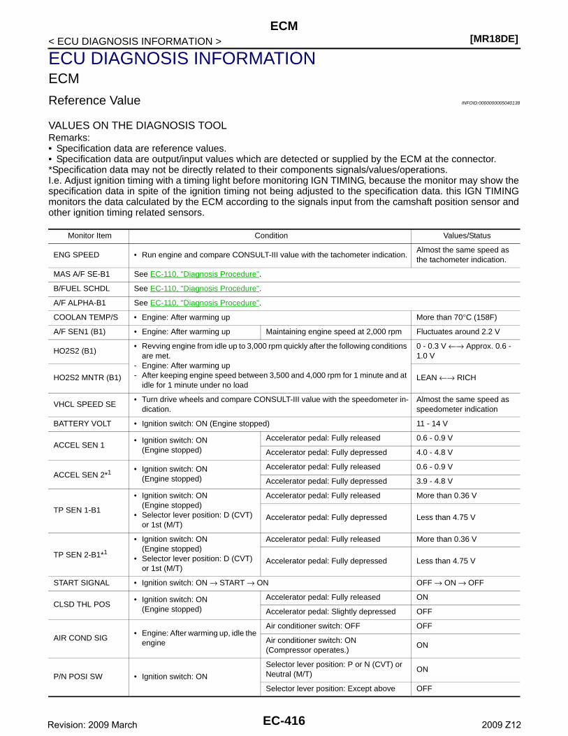
[MR18DE]ECM
< ECU DIAGNOSIS INFORMATION >
ECU DIAGNOSIS INFORMATIONECM
Reference Value INFOID:0000000005040138
VALUES ON THE DIAGNOSIS TOOLRemarks:• Specification data are reference values.• Specification data are output/input values which are detected or supplied by the ECM at the connector.*Specification data may not be directly related to their components signals/values/operations.I.e. Adjust ignition timing with a timing light before monitoring IGN TIMING, because the monitor may show thespecification data in spite of the ignition timing not being adjusted to the specification data. this IGN TIMINGmonitors the data calculated by the ECM according to the signals input from the camshaft position sensor andother ignition timing related sensors.
Monitor Item Condition Values/Status
ENG SPEED • Run engine and compare CONSULT-III value with the tachometer indication.Almost the same speed as the tachometer indication.
MAS A/F SE-B1 See EC-110, "Diagnosis Procedure".
B/FUEL SCHDL See EC-110, "Diagnosis Procedure".
A/F ALPHA-B1 See EC-110, "Diagnosis Procedure".
COOLAN TEMP/S • Engine: After warming up More than 70°C (158F)
A/F SEN1 (B1) • Engine: After warming up Maintaining engine speed at 2,000 rpm Fluctuates around 2.2 V
HO2S2 (B1)• Revving engine from idle up to 3,000 rpm quickly after the following conditions
are met.- Engine: After warming up- After keeping engine speed between 3,500 and 4,000 rpm for 1 minute and at
idle for 1 minute under no load
0 - 0.3 V ←→ Approx. 0.6 - 1.0 V
HO2S2 MNTR (B1) LEAN ←→ RICH
VHCL SPEED SE• Turn drive wheels and compare CONSULT-III value with the speedometer in-
dication.Almost the same speed as speedometer indication
BATTERY VOLT • Ignition switch: ON (Engine stopped) 11 - 14 V
ACCEL SEN 1• Ignition switch: ON
(Engine stopped)
Accelerator pedal: Fully released 0.6 - 0.9 V
Accelerator pedal: Fully depressed 4.0 - 4.8 V
ACCEL SEN 2*1 • Ignition switch: ON(Engine stopped)
Accelerator pedal: Fully released 0.6 - 0.9 V
Accelerator pedal: Fully depressed 3.9 - 4.8 V
TP SEN 1-B1
• Ignition switch: ON(Engine stopped)
• Selector lever position: D (CVT) or 1st (M/T)
Accelerator pedal: Fully released More than 0.36 V
Accelerator pedal: Fully depressed Less than 4.75 V
TP SEN 2-B1*1
• Ignition switch: ON(Engine stopped)
• Selector lever position: D (CVT) or 1st (M/T)
Accelerator pedal: Fully released More than 0.36 V
Accelerator pedal: Fully depressed Less than 4.75 V
START SIGNAL • Ignition switch: ON → START → ON OFF → ON → OFF
CLSD THL POS• Ignition switch: ON
(Engine stopped)
Accelerator pedal: Fully released ON
Accelerator pedal: Slightly depressed OFF
AIR COND SIG• Engine: After warming up, idle the
engine
Air conditioner switch: OFF OFF
Air conditioner switch: ON(Compressor operates.)
ON
P/N POSI SW • Ignition switch: ON
Selector lever position: P or N (CVT) or Neutral (M/T)
ON
Selector lever position: Except above OFF
EC-416Revision: 2009 March 2009 Z12
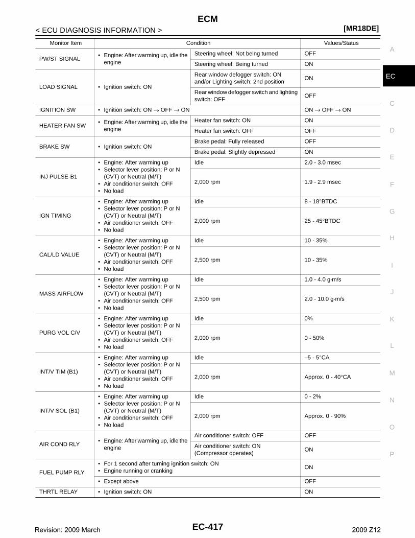
ECM[MR18DE]
C
D
E
F
G
H
I
J
K
L
M
A
C
N
P
O
< ECU DIAGNOSIS INFORMATION >
E
PW/ST SIGNAL• Engine: After warming up, idle the
engine
Steering wheel: Not being turned OFF
Steering wheel: Being turned ON
LOAD SIGNAL • Ignition switch: ON
Rear window defogger switch: ONand/or Lighting switch: 2nd position
ON
Rear window defogger switch and lighting switch: OFF
OFF
IGNITION SW • Ignition switch: ON → OFF → ON ON → OFF → ON
HEATER FAN SW• Engine: After warming up, idle the
engine
Heater fan switch: ON ON
Heater fan switch: OFF OFF
BRAKE SW • Ignition switch: ONBrake pedal: Fully released OFF
Brake pedal: Slightly depressed ON
INJ PULSE-B1
• Engine: After warming up• Selector lever position: P or N
(CVT) or Neutral (M/T) • Air conditioner switch: OFF• No load
Idle 2.0 - 3.0 msec
2,000 rpm 1.9 - 2.9 msec
IGN TIMING
• Engine: After warming up• Selector lever position: P or N
(CVT) or Neutral (M/T) • Air conditioner switch: OFF• No load
Idle 8 - 18°BTDC
2,000 rpm 25 - 45°BTDC
CAL/LD VALUE
• Engine: After warming up• Selector lever position: P or N
(CVT) or Neutral (M/T)• Air conditioner switch: OFF• No load
Idle 10 - 35%
2,500 rpm 10 - 35%
MASS AIRFLOW
• Engine: After warming up• Selector lever position: P or N
(CVT) or Neutral (M/T) • Air conditioner switch: OFF• No load
Idle 1.0 - 4.0 g·m/s
2,500 rpm 2.0 - 10.0 g·m/s
PURG VOL C/V
• Engine: After warming up• Selector lever position: P or N
(CVT) or Neutral (M/T)• Air conditioner switch: OFF• No load
Idle 0%
2,000 rpm 0 - 50%
INT/V TIM (B1)
• Engine: After warming up• Selector lever position: P or N
(CVT) or Neutral (M/T) • Air conditioner switch: OFF• No load
Idle −5 - 5°CA
2,000 rpm Approx. 0 - 40°CA
INT/V SOL (B1)
• Engine: After warming up• Selector lever position: P or N
(CVT) or Neutral (M/T) • Air conditioner switch: OFF• No load
Idle 0 - 2%
2,000 rpm Approx. 0 - 90%
AIR COND RLY• Engine: After warming up, idle the
engine
Air conditioner switch: OFF OFF
Air conditioner switch: ON(Compressor operates)
ON
FUEL PUMP RLY
• For 1 second after turning ignition switch: ON• Engine running or cranking
ON
• Except above OFF
THRTL RELAY • Ignition switch: ON ON
Monitor Item Condition Values/Status
EC-417Revision: 2009 March 2009 Z12
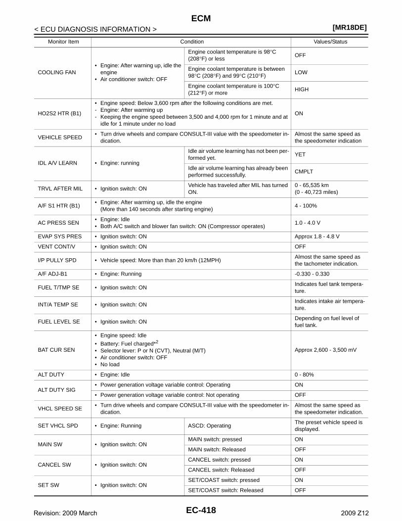
[MR18DE]ECM
< ECU DIAGNOSIS INFORMATION >
COOLING FAN• Engine: After warning up, idle the
engine• Air conditioner switch: OFF
Engine coolant temperature is 98°C (208°F) or less
OFF
Engine coolant temperature is between 98°C (208°F) and 99°C (210°F)
LOW
Engine coolant temperature is 100°C (212°F) or more
HIGH
HO2S2 HTR (B1)
• Engine speed: Below 3,600 rpm after the following conditions are met.- Engine: After warming up- Keeping the engine speed between 3,500 and 4,000 rpm for 1 minute and at
idle for 1 minute under no load
ON
VEHICLE SPEED• Turn drive wheels and compare CONSULT-III value with the speedometer in-
dication.Almost the same speed as the speedometer indication
IDL A/V LEARN • Engine: running
Idle air volume learning has not been per-formed yet.
YET
Idle air volume learning has already been performed successfully.
CMPLT
TRVL AFTER MIL • Ignition switch: ONVehicle has traveled after MIL has turned ON.
0 - 65,535 km(0 - 40,723 miles)
A/F S1 HTR (B1)• Engine: After warming up, idle the engine
(More than 140 seconds after starting engine)4 - 100%
AC PRESS SEN• Engine: Idle• Both A/C switch and blower fan switch: ON (Compressor operates)
1.0 - 4.0 V
EVAP SYS PRES • Ignition switch: ON Approx 1.8 - 4.8 V
VENT CONT/V • Ignition switch: ON OFF
I/P PULLY SPD • Vehicle speed: More than than 20 km/h (12MPH)Almost the same speed as the tachometer indication.
A/F ADJ-B1 • Engine: Running -0.330 - 0.330
FUEL T/TMP SE • Ignition switch: ONIndicates fuel tank tempera-ture.
INT/A TEMP SE • Ignition switch: ONIndicates intake air tempera-ture.
FUEL LEVEL SE • Ignition switch: ONDepending on fuel level of fuel tank.
BAT CUR SEN
• Engine speed: Idle
• Battery: Fuel charged*2
• Selector lever: P or N (CVT), Neutral (M/T)• Air conditioner switch: OFF• No load
Approx 2,600 - 3,500 mV
ALT DUTY • Engine: Idle 0 - 80%
ALT DUTY SIG• Power generation voltage variable control: Operating ON
• Power generation voltage variable control: Not operating OFF
VHCL SPEED SE• Turn drive wheels and compare CONSULT-III value with the speedometer in-
dication.Almost the same speed as the speedometer indication.
SET VHCL SPD • Engine: Running ASCD: OperatingThe preset vehicle speed is displayed.
MAIN SW • Ignition switch: ONMAIN switch: pressed ON
MAIN switch: Released OFF
CANCEL SW • Ignition switch: ONCANCEL switch: pressed ON
CANCEL switch: Released OFF
SET SW • Ignition switch: ONSET/COAST switch: pressed ON
SET/COAST switch: Released OFF
Monitor Item Condition Values/Status
EC-418Revision: 2009 March 2009 Z12
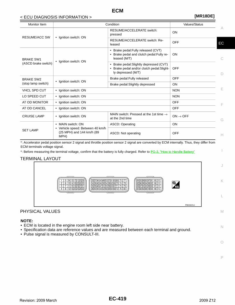
ECM[MR18DE]
C
D
E
F
G
H
I
J
K
L
M
A
C
N
P
O
< ECU DIAGNOSIS INFORMATION >
E
*: Accelerator pedal position sensor 2 signal and throttle position sensor 2 signal are converted by ECM internally. Thus, they differ fromECM terminals voltage signal.
*: Before measuring the terminal voltage, confirm that the battery is fully charged. Refer to PG-3, "How to Handle Battery"
TERMINAL LAYOUT
PHYSICAL VALUES
NOTE:• ECM is located in the engine room left side near battery. • Specification data are reference values and are measured between each terminal and ground.• Pulse signal is measured by CONSULT-III.
RESUME/ACC SW • Ignition switch: ON
RESUME/ACCELERATE switch: pressed
ON
RESUME/ACCELERATE switch: Re-leased
OFF
BRAKE SW1(ASCD brake switch)
• Ignition switch: ON
• Brake pedal:Fully released (CVT)• Brake pedal and clutch pedal:Fully re-
leased (M/T)ON
• Brake pedal:Slightly depressed (CVT)• Brake pedal and/or clutch pedal:Slight-
ly depressed (M/T)OFF
BRAKE SW2(stop lamp switch)
• Ignition switch: ONBrake pedal:Fully released OFF
Brake pedal:Slightly depressed ON
VHCL SPD CUT • Ignition switch: ON NON
LO SPEED CUT • Ignition switch: ON NON
AT OD MONITOR • Ignition switch: ON OFF
AT OD CANCEL • Ignition switch: ON OFF
CRUISE LAMP • Ignition switch: ONMAIN switch: Pressed at the 1st time → at the 2nd time
ON → OFF
SET LAMP
• MAIN switch: ON• Vehicle speed: Between 40 km/h
(25 MPH) and 144 km/h (89 MPH)
ASCD: Operating ON
ASCD: Not operating OFF
Monitor Item Condition Values/Status
PBIA9221J
EC-419Revision: 2009 March 2009 Z12
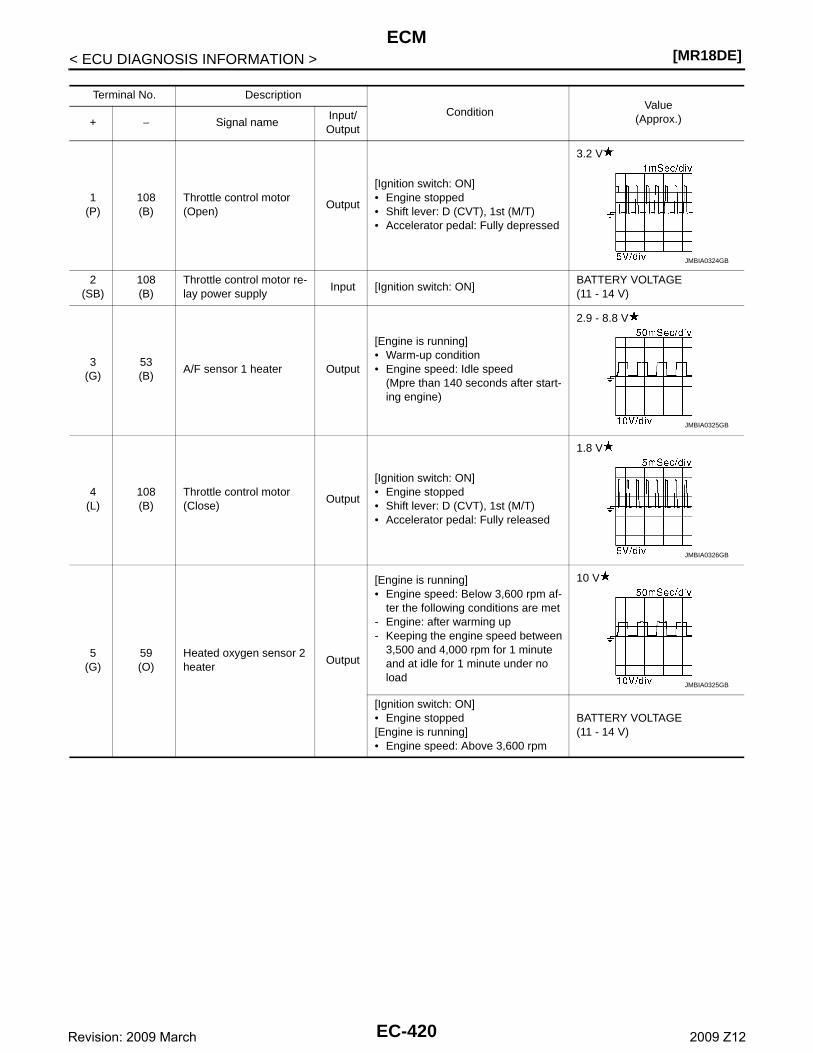
[MR18DE]ECM
< ECU DIAGNOSIS INFORMATION >
Terminal No. Description
ConditionValue
(Approx.)+ − Signal nameInput/Output
1(P)
108(B)
Throttle control motor (Open)
Output
[Ignition switch: ON]• Engine stopped• Shift lever: D (CVT), 1st (M/T) • Accelerator pedal: Fully depressed
3.2 V
2(SB)
108(B)
Throttle control motor re-lay power supply
Input [Ignition switch: ON]BATTERY VOLTAGE(11 - 14 V)
3(G)
53(B)
A/F sensor 1 heater Output
[Engine is running]• Warm-up condition• Engine speed: Idle speed
(Mpre than 140 seconds after start-ing engine)
2.9 - 8.8 V
4(L)
108(B)
Throttle control motor (Close)
Output
[Ignition switch: ON]• Engine stopped• Shift lever: D (CVT), 1st (M/T) • Accelerator pedal: Fully released
1.8 V
5(G)
59(O)
Heated oxygen sensor 2 heater
Output
[Engine is running]• Engine speed: Below 3,600 rpm af-
ter the following conditions are met- Engine: after warming up- Keeping the engine speed between
3,500 and 4,000 rpm for 1 minute and at idle for 1 minute under no load
10 V
[Ignition switch: ON]• Engine stopped[Engine is running]• Engine speed: Above 3,600 rpm
BATTERY VOLTAGE(11 - 14 V)
JMBIA0324GB
JMBIA0325GB
JMBIA0326GB
JMBIA0325GB
EC-420Revision: 2009 March 2009 Z12
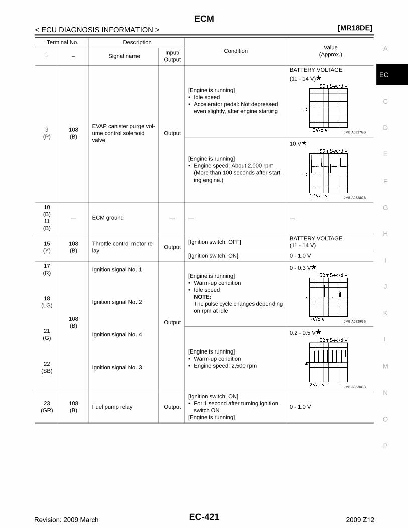
ECM[MR18DE]
C
D
E
F
G
H
I
J
K
L
M
A
C
N
P
O
< ECU DIAGNOSIS INFORMATION >
E
9(P)
108(B)
EVAP canister purge vol-ume control solenoid valve
Output
[Engine is running]• Idle speed• Accelerator pedal: Not depressed
even slightly, after engine starting
BATTERY VOLTAGE
(11 - 14 V)
[Engine is running]• Engine speed: About 2,000 rpm
(More than 100 seconds after start-ing engine.)
10 V
10(B)11(B)
— ECM ground — — —
15(Y)
108(B)
Throttle control motor re-lay
Output[Ignition switch: OFF]
BATTERY VOLTAGE(11 - 14 V)
[Ignition switch: ON] 0 - 1.0 V
17(R)
108(B)
Ignition signal No. 1
Output
[Engine is running]• Warm-up condition• Idle speed
NOTE:The pulse cycle changes depending on rpm at idle
0 - 0.3 V
18(LG)
Ignition signal No. 2
21(G)
Ignition signal No. 4
[Engine is running]• Warm-up condition• Engine speed: 2,500 rpm
0.2 - 0.5 V
22(SB)
Ignition signal No. 3
23(GR)
108(B)
Fuel pump relay Output
[Ignition switch: ON]• For 1 second after turning ignition
switch ON[Engine is running]
0 - 1.0 V
Terminal No. Description
ConditionValue
(Approx.)+ − Signal nameInput/Output
JMBIA0327GB
JMBIA0328GB
JMBIA0329GB
JMBIA0330GB
EC-421Revision: 2009 March 2009 Z12
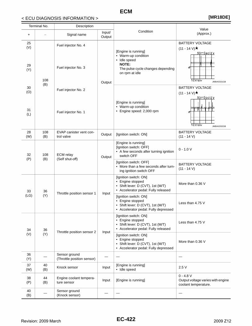
[MR18DE]ECM
< ECU DIAGNOSIS INFORMATION >
25(V)
108(B)
Fuel injector No. 4
Output
[Engine is running]• Warm-up condition• Idle speed
NOTE:The pulse cycle changes depending on rpm at idle
BATTERY VOLTAGE
(11 - 14 V)
29(Y)
Fuel injector No. 3
30(O)
Fuel injector No. 2
[Engine is running]• Warm-up condition• Engine speed: 2,000 rpm
BATTERY VOLTAGE
(11 - 14 V)
31(L)
Fuel injector No. 1
28(W)
108(B)
EVAP canister vent con-trol valve
Output [Ignition switch: ON]BATTERY VOLTAGE(11 - 14 V)
32(P)
108(B)
ECM relay(Self shut-off)
Output
[Engine is running][Ignition switch: OFF]• A few seconds after turning ignition
switch OFF
0 - 1.0 V
[Ignition switch: OFF]• More than a few seconds after turn-
ing ignition switch OFF
BATTERY VOLTAGE(11 - 14 V)
33(LG)
36(Y)
Throttle position sensor 1 Input
[Ignition switch: ON]• Engine stopped• Shift lever: D (CVT), 1st (M/T)• Accelerator pedal: Fully released
More than 0.36 V
[Ignition switch: ON]• Engine stopped• Shift lever: D (CVT), 1st (M/T)• Accelerator pedal: Fully depressed
Less than 4.75 V
34(V)
36(Y)
Throttle position sensor 2 Input
[Ignition switch: ON]• Engine stopped• Shift lever: D (CVT), 1st (M/T)• Accelerator pedal: Fully released
Less than 4.75 V
[Ignition switch: ON]• Engine stopped• Shift lever: D (CVT), 1st (M/T)• Accelerator pedal: Fully depressed
More than 0.36 V
36(Y)
—Sensor ground(Throttle position sensor)
— — —
37(W)
40(B)
Knock sensor Input[Engine is running]• Idle speed
2.5 V
38(P)
44(B)
Engine coolant tempera-ture sensor
Input [Engine is running]0 - 4.8 VOutput voltage varies with engine coolant temperature.
40(B)
—Sensor ground(Knock sensor)
— — —
Terminal No. Description
ConditionValue
(Approx.)+ − Signal nameInput/Output
JMBIA0331GB
JMBIA0332GB
EC-422Revision: 2009 March 2009 Z12
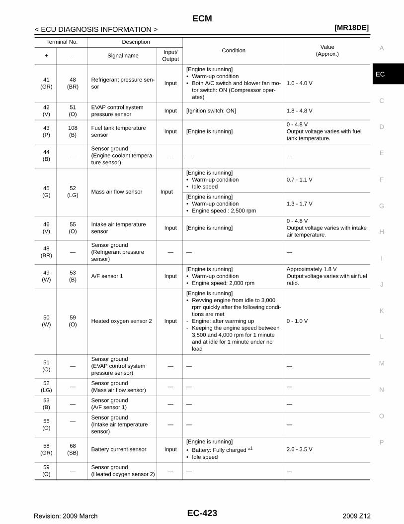
ECM[MR18DE]
C
D
E
F
G
H
I
J
K
L
M
A
C
N
P
O
< ECU DIAGNOSIS INFORMATION >
E41
(GR)48
(BR)Refrigerant pressure sen-sor
Input
[Engine is running]• Warm-up condition• Both A/C switch and blower fan mo-
tor switch: ON (Compressor oper-ates)
1.0 - 4.0 V
42(V)
51(O)
EVAP control system pressure sensor
Input [Ignition switch: ON] 1.8 - 4.8 V
43(P)
108(B)
Fuel tank temperature sensor
Input [Engine is running]0 - 4.8 VOutput voltage varies with fuel tank temperature.
44(B)
—Sensor ground(Engine coolant tempera-ture sensor)
— — —
45(G)
52(LG)
Mass air flow sensor Input
[Engine is running]• Warm-up condition• Idle speed
0.7 - 1.1 V
[Engine is running]• Warm-up condition• Engine speed : 2,500 rpm
1.3 - 1.7 V
46(V)
55(O)
Intake air temperature sensor
Input [Engine is running]0 - 4.8 VOutput voltage varies with intake air temperature.
48(BR)
—Sensor ground(Refrigerant pressure sensor)
— — —
49(W)
53(B)
A/F sensor 1 Input[Engine is running]• Warm-up condition• Engine speed: 2,000 rpm
Approximately 1.8 VOutput voltage varies with air fuel ratio.
50(W)
59(O)
Heated oxygen sensor 2 Input
[Engine is running]• Revving engine from idle to 3,000
rpm quickly after the following condi-tions are met
- Engine: after warming up- Keeping the engine speed between
3,500 and 4,000 rpm for 1 minute and at idle for 1 minute under no load
0 - 1.0 V
51(O)
—Sensor ground(EVAP control system pressure sensor)
— — —
52(LG)
—Sensor ground(Mass air flow sensor)
— — —
53(B)
—Sensor ground(A/F sensor 1)
— — —
55(O)
—Sensor ground(Intake air temperature sensor)
— — —
58(GR)
68(SB)
Battery current sensor Input[Engine is running]
• Battery: Fully charged *1
• Idle speed2.6 - 3.5 V
59(O)
—Sensor ground(Heated oxygen sensor 2)
— — —
Terminal No. Description
ConditionValue
(Approx.)+ − Signal nameInput/Output
EC-423Revision: 2009 March 2009 Z12
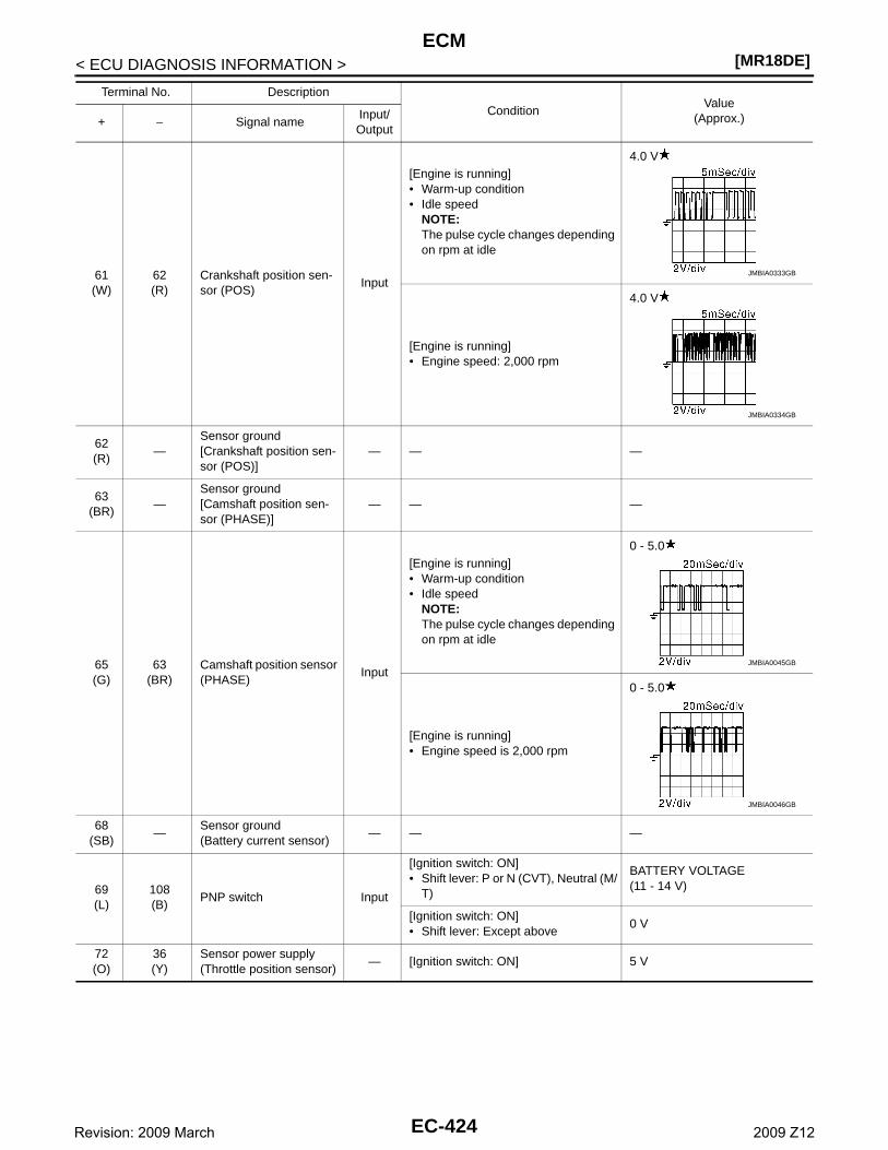
[MR18DE]ECM
< ECU DIAGNOSIS INFORMATION >
61(W)
62(R)
Crankshaft position sen-sor (POS)
Input
[Engine is running]• Warm-up condition• Idle speed
NOTE:The pulse cycle changes depending on rpm at idle
4.0 V
[Engine is running]• Engine speed: 2,000 rpm
4.0 V
62(R)
—Sensor ground[Crankshaft position sen-sor (POS)]
— — —
63(BR)
—Sensor ground[Camshaft position sen-sor (PHASE)]
— — —
65(G)
63(BR)
Camshaft position sensor (PHASE)
Input
[Engine is running]• Warm-up condition• Idle speed
NOTE:The pulse cycle changes depending on rpm at idle
0 - 5.0
[Engine is running]• Engine speed is 2,000 rpm
0 - 5.0
68(SB)
—Sensor ground(Battery current sensor)
— — —
69(L)
108(B)
PNP switch Input
[Ignition switch: ON]• Shift lever: P or N (CVT), Neutral (M/
T)
BATTERY VOLTAGE(11 - 14 V)
[Ignition switch: ON]• Shift lever: Except above
0 V
72(O)
36(Y)
Sensor power supply(Throttle position sensor)
— [Ignition switch: ON] 5 V
Terminal No. Description
ConditionValue
(Approx.)+ − Signal nameInput/Output
JMBIA0333GB
JMBIA0334GB
JMBIA0045GB
JMBIA0046GB
EC-424Revision: 2009 March 2009 Z12
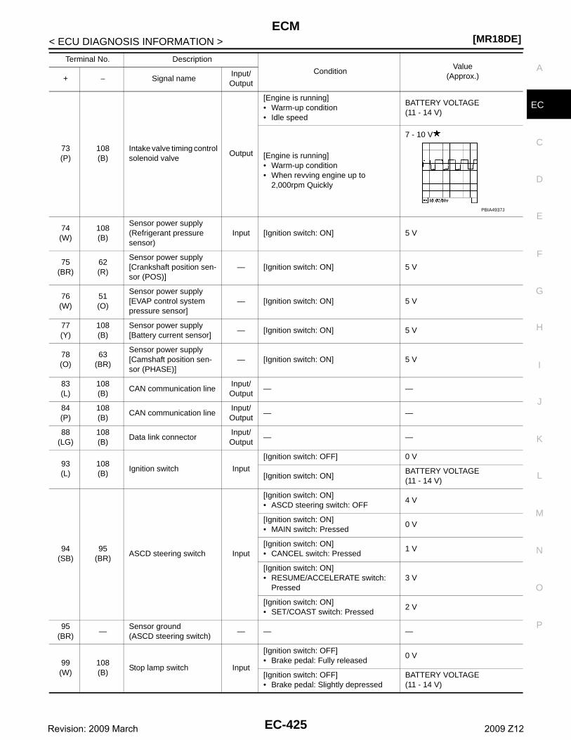
ECM[MR18DE]
C
D
E
F
G
H
I
J
K
L
M
A
C
N
P
O
< ECU DIAGNOSIS INFORMATION >
E
73(P)
108(B)
Intake valve timing control solenoid valve
Output
[Engine is running]• Warm-up condition• Idle speed
BATTERY VOLTAGE(11 - 14 V)
[Engine is running]• Warm-up condition• When revving engine up to
2,000rpm Quickly
7 - 10 V
74(W)
108(B)
Sensor power supply(Refrigerant pressure sensor)
Input [Ignition switch: ON] 5 V
75(BR)
62(R)
Sensor power supply[Crankshaft position sen-sor (POS)]
— [Ignition switch: ON] 5 V
76(W)
51(O)
Sensor power supply[EVAP control system pressure sensor]
— [Ignition switch: ON] 5 V
77(Y)
108(B)
Sensor power supply[Battery current sensor]
— [Ignition switch: ON] 5 V
78(O)
63(BR)
Sensor power supply[Camshaft position sen-sor (PHASE)]
— [Ignition switch: ON] 5 V
83(L)
108(B)
CAN communication lineInput/Output
— —
84(P)
108(B)
CAN communication lineInput/Output
— —
88(LG)
108(B)
Data link connectorInput/Output
— —
93(L)
108(B)
Ignition switch Input
[Ignition switch: OFF] 0 V
[Ignition switch: ON]BATTERY VOLTAGE(11 - 14 V)
94(SB)
95(BR)
ASCD steering switch Input
[Ignition switch: ON]• ASCD steering switch: OFF
4 V
[Ignition switch: ON]• MAIN switch: Pressed
0 V
[Ignition switch: ON]• CANCEL switch: Pressed
1 V
[Ignition switch: ON]• RESUME/ACCELERATE switch:
Pressed3 V
[Ignition switch: ON]• SET/COAST switch: Pressed
2 V
95(BR)
—Sensor ground(ASCD steering switch)
— — —
99(W)
108(B)
Stop lamp switch Input
[Ignition switch: OFF]• Brake pedal: Fully released
0 V
[Ignition switch: OFF]• Brake pedal: Slightly depressed
BATTERY VOLTAGE(11 - 14 V)
Terminal No. Description
ConditionValue
(Approx.)+ − Signal nameInput/Output
PBIA4937J
EC-425Revision: 2009 March 2009 Z12
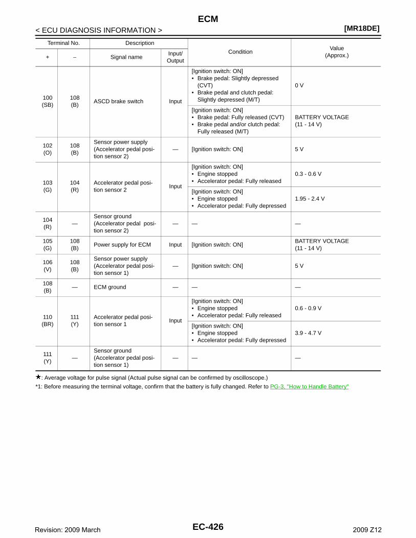
[MR18DE]ECM
< ECU DIAGNOSIS INFORMATION >
: Average voltage for pulse signal (Actual pulse signal can be confirmed by oscilloscope.)
*1: Before measuring the terminal voltage, confirm that the battery is fully changed. Refer to PG-3, "How to Handle Battery"
100(SB)
108(B)
ASCD brake switch Input
[Ignition switch: ON]• Brake pedal: Slightly depressed
(CVT)• Brake pedal and clutch pedal:
Slightly depressed (M/T)
0 V
[Ignition switch: ON]• Brake pedal: Fully released (CVT)• Brake pedal and/or clutch pedal:
Fully released (M/T)
BATTERY VOLTAGE(11 - 14 V)
102(O)
108(B)
Sensor power supply(Accelerator pedal posi-tion sensor 2)
— [Ignition switch: ON] 5 V
103(G)
104(R)
Accelerator pedal posi-tion sensor 2
Input
[Ignition switch: ON]• Engine stopped• Accelerator pedal: Fully released
0.3 - 0.6 V
[Ignition switch: ON]• Engine stopped• Accelerator pedal: Fully depressed
1.95 - 2.4 V
104(R)
—Sensor ground(Accelerator pedal posi-tion sensor 2)
— — —
105(G)
108(B)
Power supply for ECM Input [Ignition switch: ON]BATTERY VOLTAGE(11 - 14 V)
106(V)
108(B)
Sensor power supply(Accelerator pedal posi-tion sensor 1)
— [Ignition switch: ON] 5 V
108(B)
— ECM ground — — —
110(BR)
111(Y)
Accelerator pedal posi-tion sensor 1
Input
[Ignition switch: ON]• Engine stopped• Accelerator pedal: Fully released
0.6 - 0.9 V
[Ignition switch: ON]• Engine stopped• Accelerator pedal: Fully depressed
3.9 - 4.7 V
111(Y)
—Sensor ground(Accelerator pedal posi-tion sensor 1)
— — —
Terminal No. Description
ConditionValue
(Approx.)+ − Signal nameInput/Output
EC-426Revision: 2009 March 2009 Z12
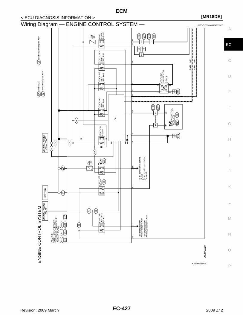
ECM[MR18DE]
C
D
E
F
G
H
I
J
K
L
M
A
C
N
P
O
< ECU DIAGNOSIS INFORMATION >
E
Wiring Diagram — ENGINE CONTROL SYSTEM — INFOID:0000000004833547
JCBWM1288GB
EC-427Revision: 2009 March 2009 Z12
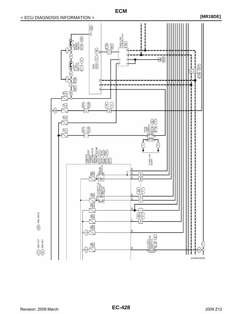
[MR18DE]ECM
< ECU DIAGNOSIS INFORMATION >
JCBWM1289GB
EC-428Revision: 2009 March 2009 Z12
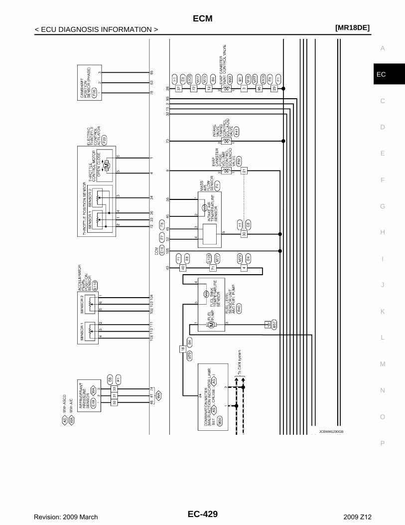
ECM[MR18DE]
C
D
E
F
G
H
I
J
K
L
M
A
C
N
P
O
< ECU DIAGNOSIS INFORMATION >
E
JCBWM1290GB
EC-429Revision: 2009 March 2009 Z12
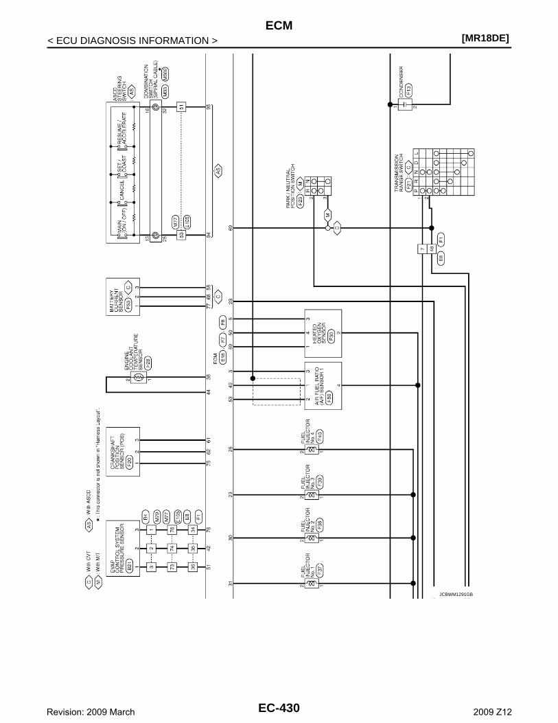
[MR18DE]ECM
< ECU DIAGNOSIS INFORMATION >
JCBWM1291GB
EC-430Revision: 2009 March 2009 Z12
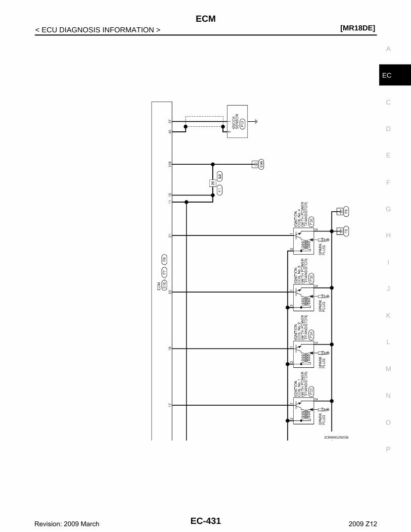
ECM[MR18DE]
C
D
E
F
G
H
I
J
K
L
M
A
C
N
P
O
< ECU DIAGNOSIS INFORMATION >
E
JCBWM1292GB
EC-431Revision: 2009 March 2009 Z12
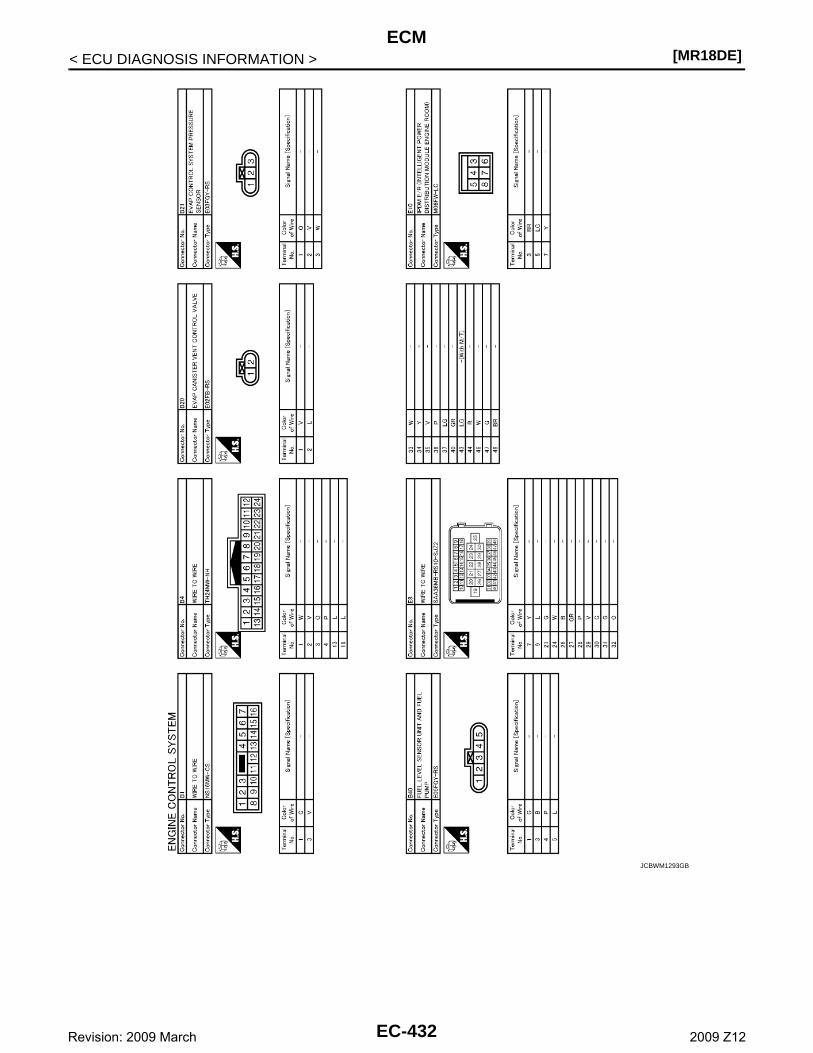
[MR18DE]ECM
< ECU DIAGNOSIS INFORMATION >
JCBWM1293GB
EC-432Revision: 2009 March 2009 Z12

ECM[MR18DE]
C
D
E
F
G
H
I
J
K
L
M
A
C
N
P
O
< ECU DIAGNOSIS INFORMATION >
E
JCBWM1294GB
EC-433Revision: 2009 March 2009 Z12
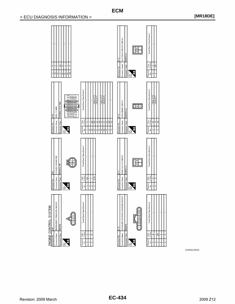
[MR18DE]ECM
< ECU DIAGNOSIS INFORMATION >
JCBWM1295GB
EC-434Revision: 2009 March 2009 Z12
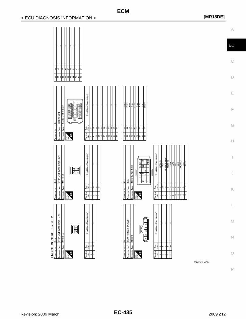
ECM[MR18DE]
C
D
E
F
G
H
I
J
K
L
M
A
C
N
P
O
< ECU DIAGNOSIS INFORMATION >
E
JCBWM1296GB
EC-435Revision: 2009 March 2009 Z12
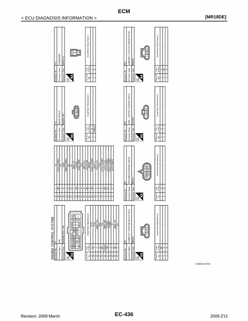
[MR18DE]ECM
< ECU DIAGNOSIS INFORMATION >
JCBWM1297GB
EC-436Revision: 2009 March 2009 Z12
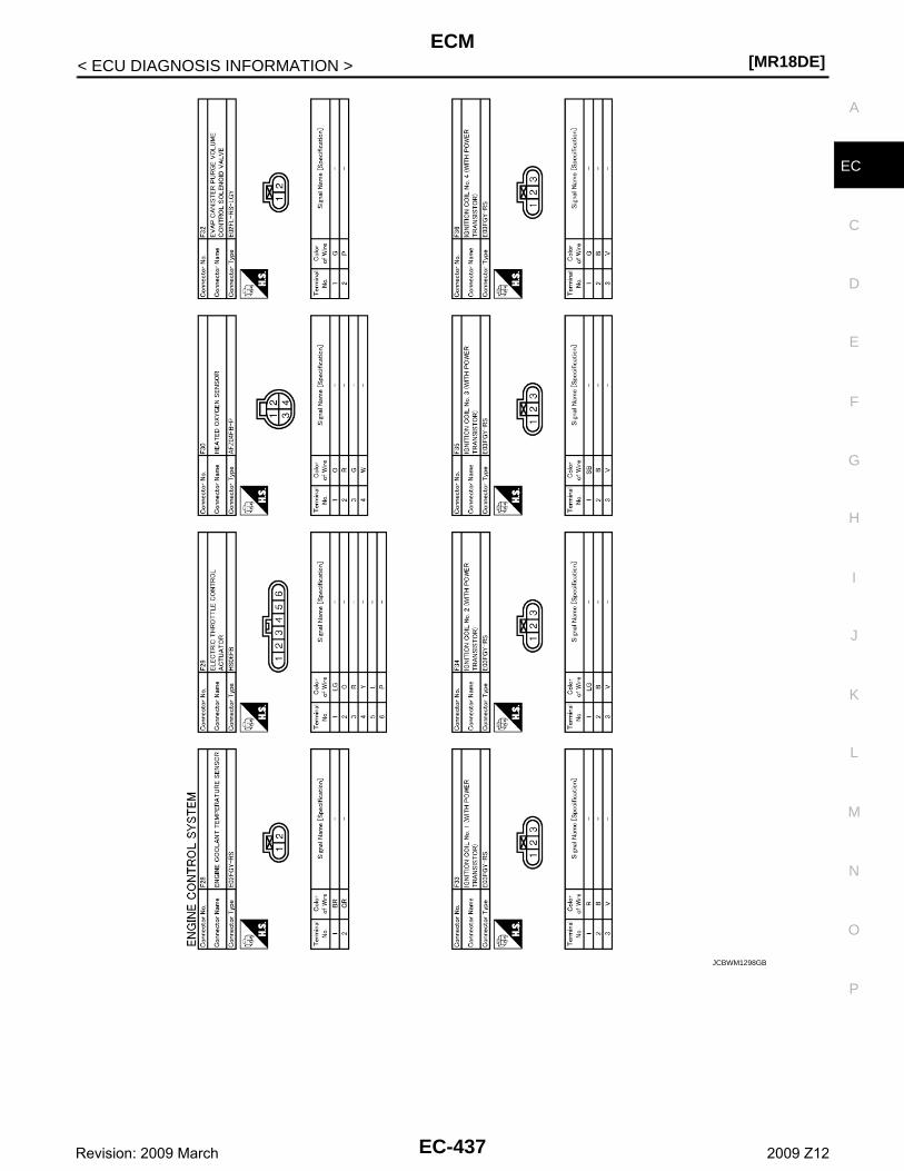
ECM[MR18DE]
C
D
E
F
G
H
I
J
K
L
M
A
C
N
P
O
< ECU DIAGNOSIS INFORMATION >
E
JCBWM1298GB
EC-437Revision: 2009 March 2009 Z12
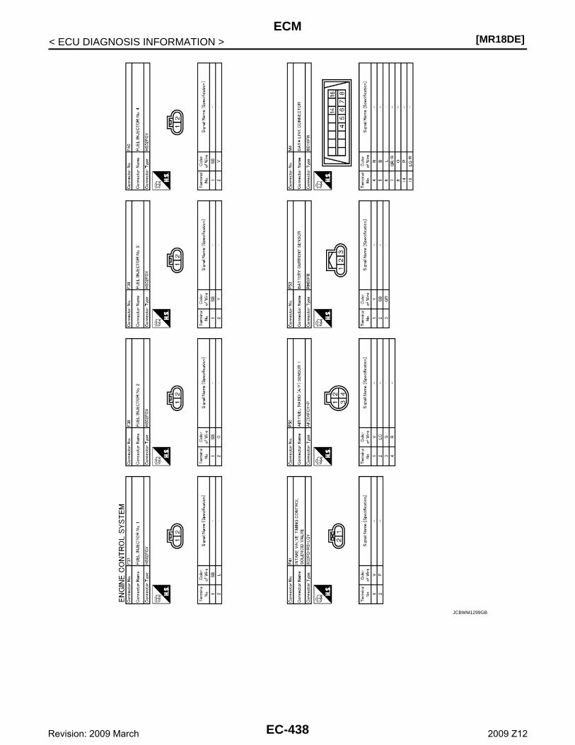
[MR18DE]ECM
< ECU DIAGNOSIS INFORMATION >
JCBWM1299GB
EC-438Revision: 2009 March 2009 Z12
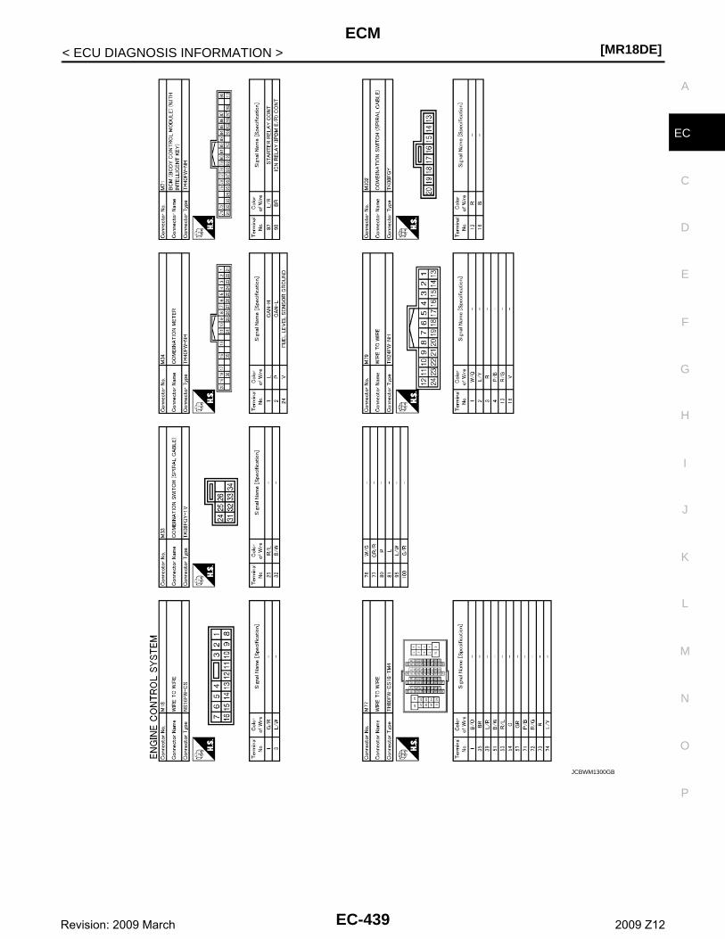
ECM[MR18DE]
C
D
E
F
G
H
I
J
K
L
M
A
C
N
P
O
< ECU DIAGNOSIS INFORMATION >
E
JCBWM1300GB
EC-439Revision: 2009 March 2009 Z12
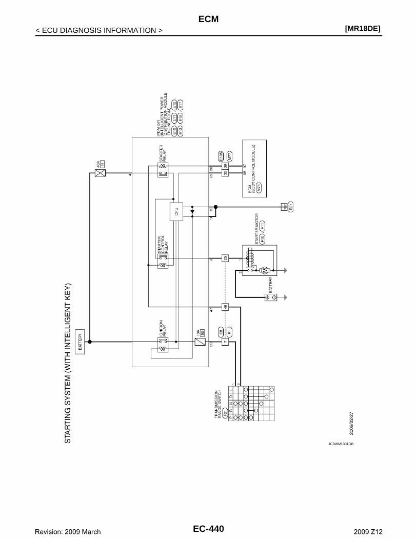
[MR18DE]ECM
< ECU DIAGNOSIS INFORMATION >
JCBWM1301GB
EC-440Revision: 2009 March 2009 Z12
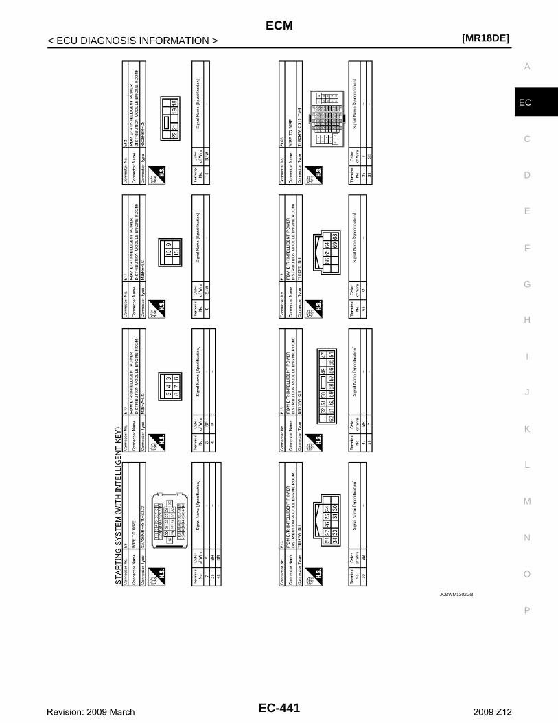
ECM[MR18DE]
C
D
E
F
G
H
I
J
K
L
M
A
C
N
P
O
< ECU DIAGNOSIS INFORMATION >
E
JCBWM1302GB
EC-441Revision: 2009 March 2009 Z12
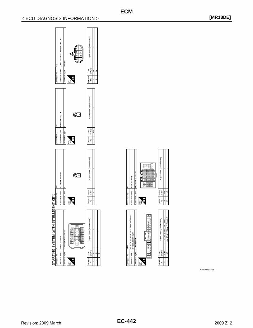
[MR18DE]ECM
< ECU DIAGNOSIS INFORMATION >
JCBWM1303GB
EC-442Revision: 2009 March 2009 Z12
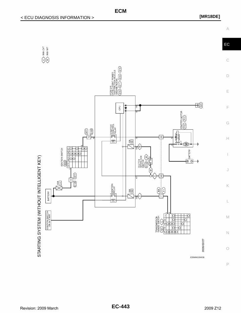
ECM[MR18DE]
C
D
E
F
G
H
I
J
K
L
M
A
C
N
P
O
< ECU DIAGNOSIS INFORMATION >
E
JCBWM1304GB
EC-443Revision: 2009 March 2009 Z12
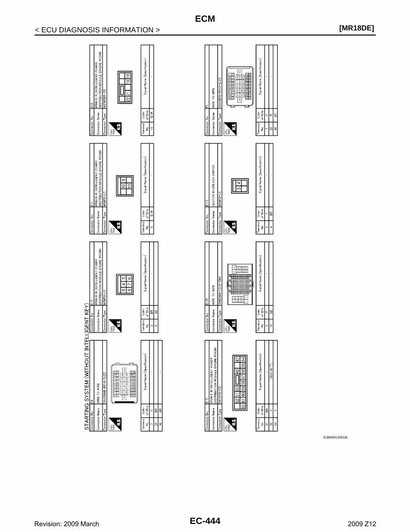
[MR18DE]ECM
< ECU DIAGNOSIS INFORMATION >
JCBWM1305GB
EC-444Revision: 2009 March 2009 Z12
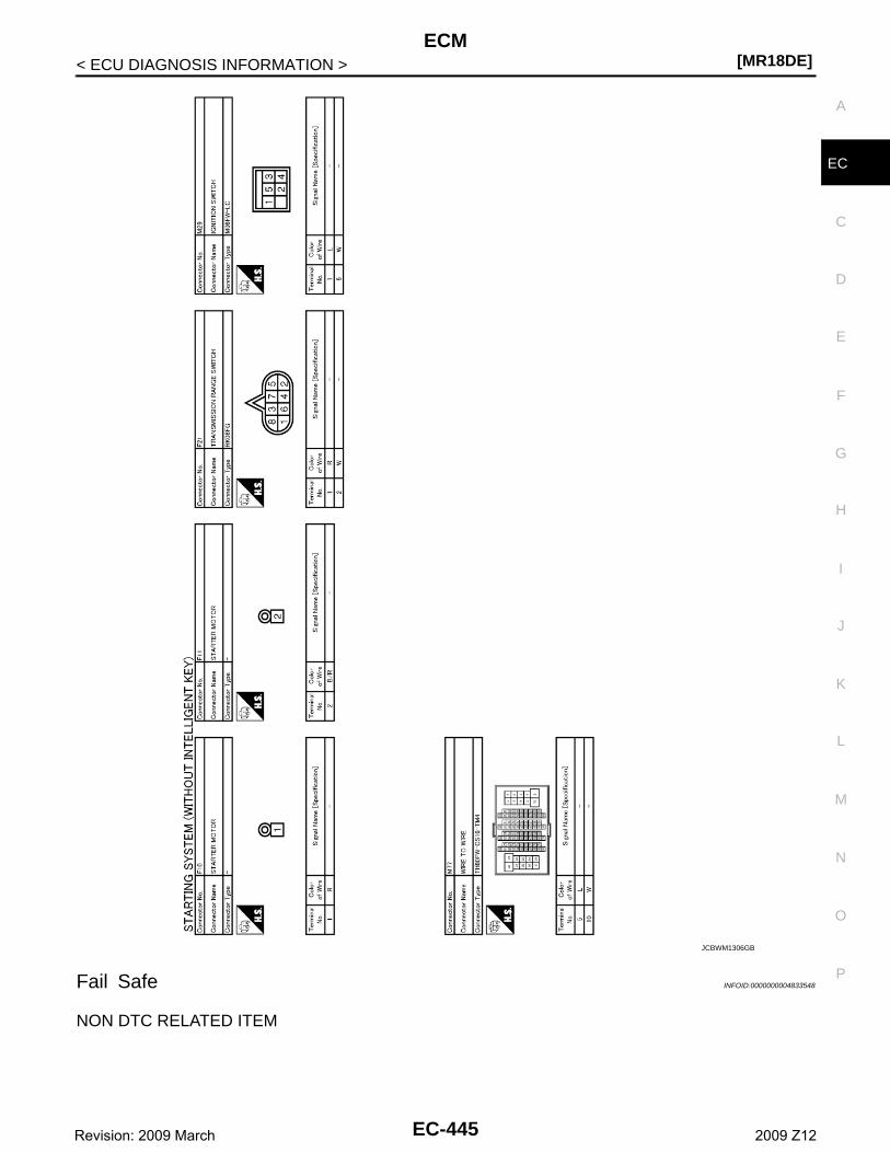
ECM[MR18DE]
C
D
E
F
G
H
I
J
K
L
M
A
C
N
P
O
< ECU DIAGNOSIS INFORMATION >
E
Fail Safe INFOID:0000000004833548
NON DTC RELATED ITEM
JCBWM1306GB
EC-445Revision: 2009 March 2009 Z12
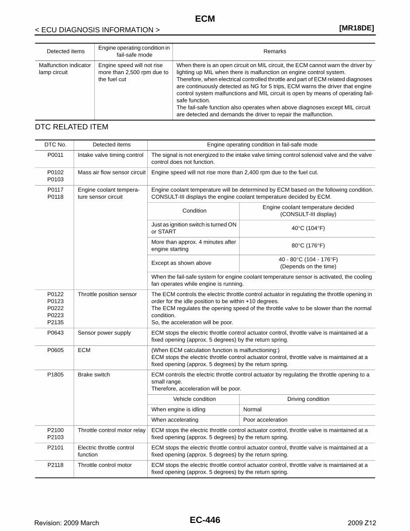
[MR18DE]ECM
< ECU DIAGNOSIS INFORMATION >
DTC RELATED ITEM
Detected itemsEngine operating condition in
fail-safe modeRemarks
Malfunction indicator lamp circuit
Engine speed will not rise more than 2,500 rpm due to the fuel cut
When there is an open circuit on MIL circuit, the ECM cannot warn the driver by lighting up MIL when there is malfunction on engine control system.Therefore, when electrical controlled throttle and part of ECM related diagnoses are continuously detected as NG for 5 trips, ECM warns the driver that engine control system malfunctions and MIL circuit is open by means of operating fail-safe function.The fail-safe function also operates when above diagnoses except MIL circuit are detected and demands the driver to repair the malfunction.
DTC No. Detected items Engine operating condition in fail-safe mode
P0011 Intake valve timing control The signal is not energized to the intake valve timing control solenoid valve and the valve control does not function.
P0102P0103
Mass air flow sensor circuit Engine speed will not rise more than 2,400 rpm due to the fuel cut.
P0117P0118
Engine coolant tempera-ture sensor circuit
Engine coolant temperature will be determined by ECM based on the following condition.CONSULT-III displays the engine coolant temperature decided by ECM.
ConditionEngine coolant temperature decided
(CONSULT-III display)
Just as ignition switch is turned ON or START
40°C (104°F)
More than approx. 4 minutes after engine starting
80°C (176°F)
Except as shown above40 - 80°C (104 - 176°F)(Depends on the time)
When the fail-safe system for engine coolant temperature sensor is activated, the cooling fan operates while engine is running.
P0122P0123P0222P0223P2135
Throttle position sensor The ECM controls the electric throttle control actuator in regulating the throttle opening in order for the idle position to be within +10 degrees.The ECM regulates the opening speed of the throttle valve to be slower than the normal condition.So, the acceleration will be poor.
P0643 Sensor power supply ECM stops the electric throttle control actuator control, throttle valve is maintained at a fixed opening (approx. 5 degrees) by the return spring.
P0605 ECM (When ECM calculation function is malfunctioning:)ECM stops the electric throttle control actuator control, throttle valve is maintained at a fixed opening (approx. 5 degrees) by the return spring.
P1805 Brake switch ECM controls the electric throttle control actuator by regulating the throttle opening to a small range.Therefore, acceleration will be poor.
Vehicle condition Driving condition
When engine is idling Normal
When accelerating Poor acceleration
P2100P2103
Throttle control motor relay ECM stops the electric throttle control actuator control, throttle valve is maintained at a fixed opening (approx. 5 degrees) by the return spring.
P2101 Electric throttle control function
ECM stops the electric throttle control actuator control, throttle valve is maintained at a fixed opening (approx. 5 degrees) by the return spring.
P2118 Throttle control motor ECM stops the electric throttle control actuator control, throttle valve is maintained at a fixed opening (approx. 5 degrees) by the return spring.
EC-446Revision: 2009 March 2009 Z12
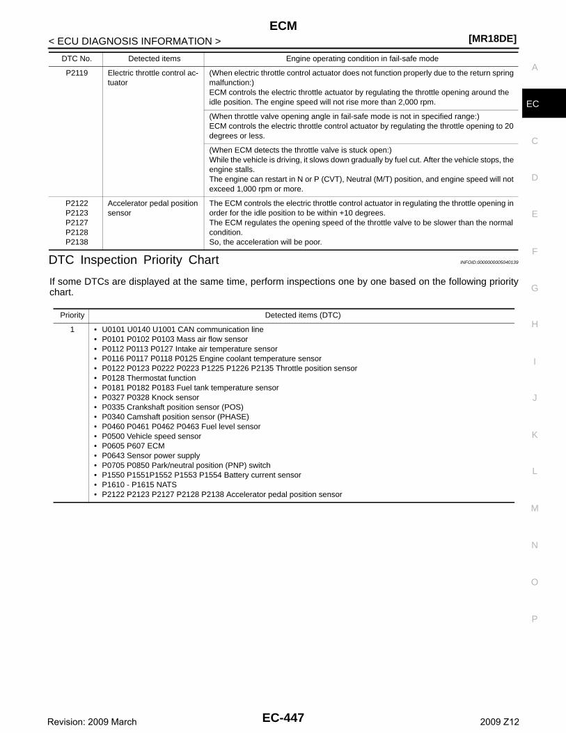
ECM[MR18DE]
C
D
E
F
G
H
I
J
K
L
M
A
C
N
P
O
< ECU DIAGNOSIS INFORMATION >
E
DTC Inspection Priority Chart INFOID:0000000005040139
If some DTCs are displayed at the same time, perform inspections one by one based on the following prioritychart.
P2119 Electric throttle control ac-tuator
(When electric throttle control actuator does not function properly due to the return spring malfunction:)ECM controls the electric throttle actuator by regulating the throttle opening around the idle position. The engine speed will not rise more than 2,000 rpm.
(When throttle valve opening angle in fail-safe mode is not in specified range:)ECM controls the electric throttle control actuator by regulating the throttle opening to 20 degrees or less.
(When ECM detects the throttle valve is stuck open:)While the vehicle is driving, it slows down gradually by fuel cut. After the vehicle stops, the engine stalls.The engine can restart in N or P (CVT), Neutral (M/T) position, and engine speed will not exceed 1,000 rpm or more.
P2122P2123P2127P2128P2138
Accelerator pedal position sensor
The ECM controls the electric throttle control actuator in regulating the throttle opening in order for the idle position to be within +10 degrees.The ECM regulates the opening speed of the throttle valve to be slower than the normal condition.So, the acceleration will be poor.
DTC No. Detected items Engine operating condition in fail-safe mode
Priority Detected items (DTC)
1 • U0101 U0140 U1001 CAN communication line• P0101 P0102 P0103 Mass air flow sensor• P0112 P0113 P0127 Intake air temperature sensor• P0116 P0117 P0118 P0125 Engine coolant temperature sensor• P0122 P0123 P0222 P0223 P1225 P1226 P2135 Throttle position sensor• P0128 Thermostat function• P0181 P0182 P0183 Fuel tank temperature sensor• P0327 P0328 Knock sensor• P0335 Crankshaft position sensor (POS)• P0340 Camshaft position sensor (PHASE)• P0460 P0461 P0462 P0463 Fuel level sensor• P0500 Vehicle speed sensor• P0605 P607 ECM• P0643 Sensor power supply• P0705 P0850 Park/neutral position (PNP) switch• P1550 P1551P1552 P1553 P1554 Battery current sensor• P1610 - P1615 NATS• P2122 P2123 P2127 P2128 P2138 Accelerator pedal position sensor
EC-447Revision: 2009 March 2009 Z12
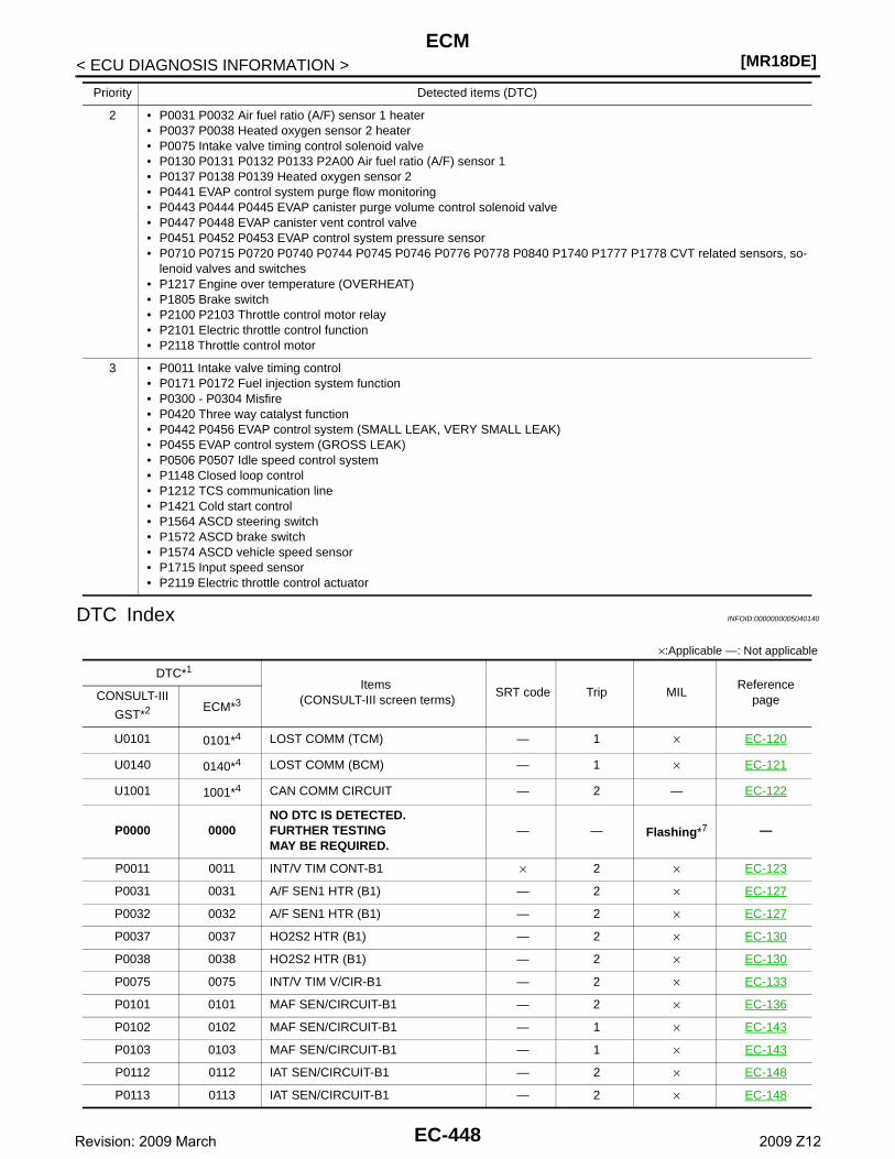
[MR18DE]ECM
< ECU DIAGNOSIS INFORMATION >
DTC Index INFOID:0000000005040140
×:Applicable —: Not applicable
2 • P0031 P0032 Air fuel ratio (A/F) sensor 1 heater• P0037 P0038 Heated oxygen sensor 2 heater• P0075 Intake valve timing control solenoid valve• P0130 P0131 P0132 P0133 P2A00 Air fuel ratio (A/F) sensor 1• P0137 P0138 P0139 Heated oxygen sensor 2• P0441 EVAP control system purge flow monitoring• P0443 P0444 P0445 EVAP canister purge volume control solenoid valve• P0447 P0448 EVAP canister vent control valve• P0451 P0452 P0453 EVAP control system pressure sensor• P0710 P0715 P0720 P0740 P0744 P0745 P0746 P0776 P0778 P0840 P1740 P1777 P1778 CVT related sensors, so-
lenoid valves and switches• P1217 Engine over temperature (OVERHEAT)• P1805 Brake switch• P2100 P2103 Throttle control motor relay• P2101 Electric throttle control function• P2118 Throttle control motor
3 • P0011 Intake valve timing control• P0171 P0172 Fuel injection system function• P0300 - P0304 Misfire• P0420 Three way catalyst function• P0442 P0456 EVAP control system (SMALL LEAK, VERY SMALL LEAK)• P0455 EVAP control system (GROSS LEAK)• P0506 P0507 Idle speed control system• P1148 Closed loop control• P1212 TCS communication line• P1421 Cold start control• P1564 ASCD steering switch• P1572 ASCD brake switch• P1574 ASCD vehicle speed sensor• P1715 Input speed sensor• P2119 Electric throttle control actuator
Priority Detected items (DTC)
DTC*1
Items (CONSULT-III screen terms)
SRT code Trip MILReference
pageCONSULT-III
GST*2 ECM*3
U0101 0101*4 LOST COMM (TCM) — 1 × EC-120
U0140 0140*4 LOST COMM (BCM) — 1 × EC-121
U1001 1001*4 CAN COMM CIRCUIT — 2 — EC-122
P0000 0000NO DTC IS DETECTED. FURTHER TESTING MAY BE REQUIRED.
— — Flashing*7 —
P0011 0011 INT/V TIM CONT-B1 × 2 × EC-123
P0031 0031 A/F SEN1 HTR (B1) — 2 × EC-127
P0032 0032 A/F SEN1 HTR (B1) — 2 × EC-127
P0037 0037 HO2S2 HTR (B1) — 2 × EC-130
P0038 0038 HO2S2 HTR (B1) — 2 × EC-130
P0075 0075 INT/V TIM V/CIR-B1 — 2 × EC-133
P0101 0101 MAF SEN/CIRCUIT-B1 — 2 × EC-136
P0102 0102 MAF SEN/CIRCUIT-B1 — 1 × EC-143
P0103 0103 MAF SEN/CIRCUIT-B1 — 1 × EC-143
P0112 0112 IAT SEN/CIRCUIT-B1 — 2 × EC-148
P0113 0113 IAT SEN/CIRCUIT-B1 — 2 × EC-148
EC-448Revision: 2009 March 2009 Z12
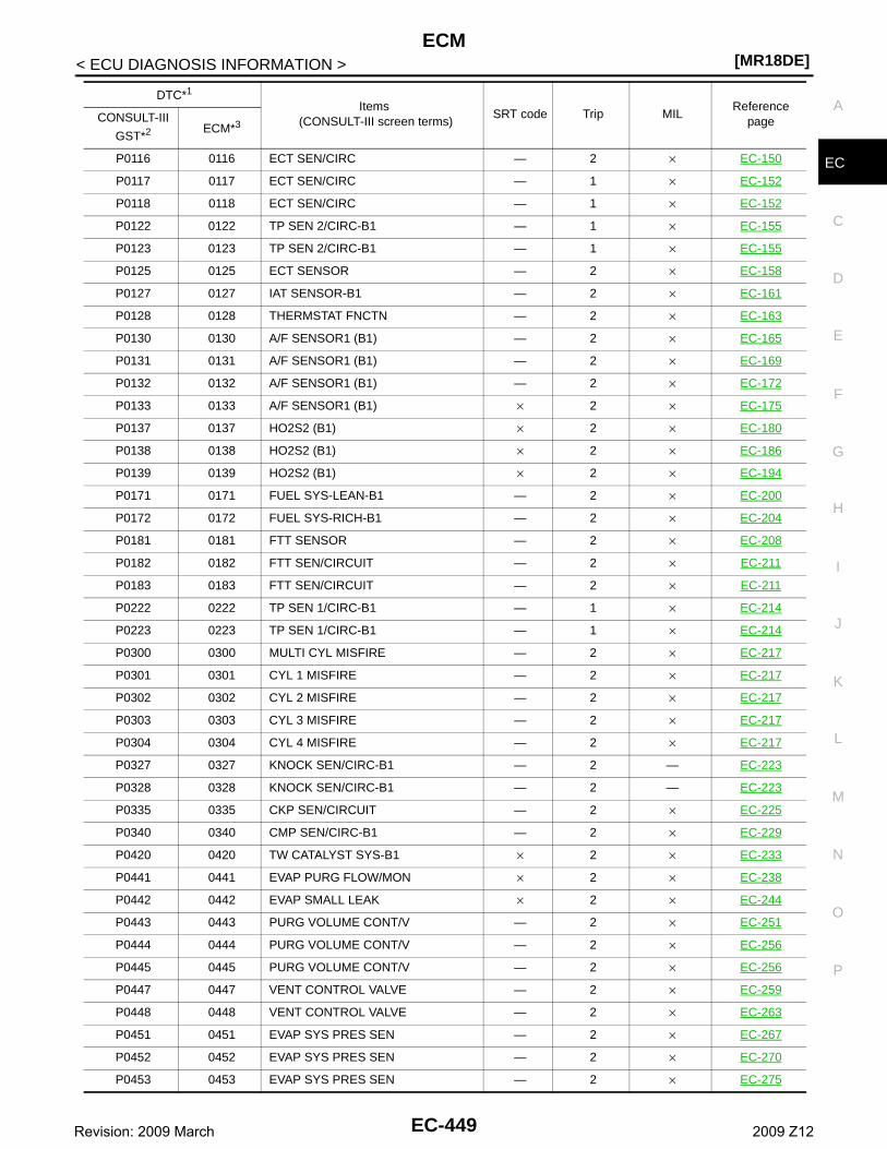
ECM[MR18DE]
C
D
E
F
G
H
I
J
K
L
M
A
C
N
P
O
< ECU DIAGNOSIS INFORMATION >
EP0116 0116 ECT SEN/CIRC — 2 × EC-150
P0117 0117 ECT SEN/CIRC — 1 × EC-152
P0118 0118 ECT SEN/CIRC — 1 × EC-152
P0122 0122 TP SEN 2/CIRC-B1 — 1 × EC-155
P0123 0123 TP SEN 2/CIRC-B1 — 1 × EC-155
P0125 0125 ECT SENSOR — 2 × EC-158
P0127 0127 IAT SENSOR-B1 — 2 × EC-161
P0128 0128 THERMSTAT FNCTN — 2 × EC-163
P0130 0130 A/F SENSOR1 (B1) — 2 × EC-165
P0131 0131 A/F SENSOR1 (B1) — 2 × EC-169
P0132 0132 A/F SENSOR1 (B1) — 2 × EC-172
P0133 0133 A/F SENSOR1 (B1) × 2 × EC-175
P0137 0137 HO2S2 (B1) × 2 × EC-180
P0138 0138 HO2S2 (B1) × 2 × EC-186
P0139 0139 HO2S2 (B1) × 2 × EC-194
P0171 0171 FUEL SYS-LEAN-B1 — 2 × EC-200
P0172 0172 FUEL SYS-RICH-B1 — 2 × EC-204
P0181 0181 FTT SENSOR — 2 × EC-208
P0182 0182 FTT SEN/CIRCUIT — 2 × EC-211
P0183 0183 FTT SEN/CIRCUIT — 2 × EC-211
P0222 0222 TP SEN 1/CIRC-B1 — 1 × EC-214
P0223 0223 TP SEN 1/CIRC-B1 — 1 × EC-214
P0300 0300 MULTI CYL MISFIRE — 2 × EC-217
P0301 0301 CYL 1 MISFIRE — 2 × EC-217
P0302 0302 CYL 2 MISFIRE — 2 × EC-217
P0303 0303 CYL 3 MISFIRE — 2 × EC-217
P0304 0304 CYL 4 MISFIRE — 2 × EC-217
P0327 0327 KNOCK SEN/CIRC-B1 — 2 — EC-223
P0328 0328 KNOCK SEN/CIRC-B1 — 2 — EC-223
P0335 0335 CKP SEN/CIRCUIT — 2 × EC-225
P0340 0340 CMP SEN/CIRC-B1 — 2 × EC-229
P0420 0420 TW CATALYST SYS-B1 × 2 × EC-233
P0441 0441 EVAP PURG FLOW/MON × 2 × EC-238
P0442 0442 EVAP SMALL LEAK × 2 × EC-244
P0443 0443 PURG VOLUME CONT/V — 2 × EC-251
P0444 0444 PURG VOLUME CONT/V — 2 × EC-256
P0445 0445 PURG VOLUME CONT/V — 2 × EC-256
P0447 0447 VENT CONTROL VALVE — 2 × EC-259
P0448 0448 VENT CONTROL VALVE — 2 × EC-263
P0451 0451 EVAP SYS PRES SEN — 2 × EC-267
P0452 0452 EVAP SYS PRES SEN — 2 × EC-270
P0453 0453 EVAP SYS PRES SEN — 2 × EC-275
DTC*1
Items (CONSULT-III screen terms)
SRT code Trip MILReference
pageCONSULT-III
GST*2 ECM*3
EC-449Revision: 2009 March 2009 Z12
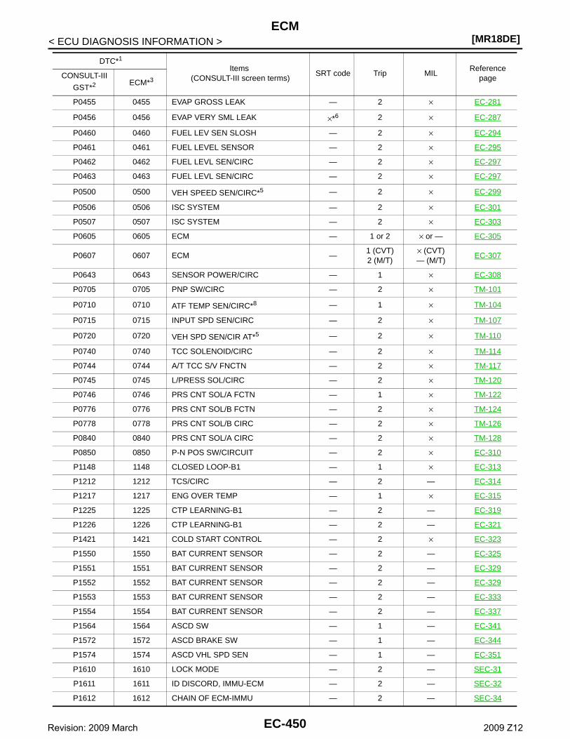
[MR18DE]ECM
< ECU DIAGNOSIS INFORMATION >
P0455 0455 EVAP GROSS LEAK — 2 × EC-281
P0456 0456 EVAP VERY SML LEAK ×*6 2 × EC-287
P0460 0460 FUEL LEV SEN SLOSH — 2 × EC-294
P0461 0461 FUEL LEVEL SENSOR — 2 × EC-295
P0462 0462 FUEL LEVL SEN/CIRC — 2 × EC-297
P0463 0463 FUEL LEVL SEN/CIRC — 2 × EC-297
P0500 0500 VEH SPEED SEN/CIRC*5 — 2 × EC-299
P0506 0506 ISC SYSTEM — 2 × EC-301
P0507 0507 ISC SYSTEM — 2 × EC-303
P0605 0605 ECM — 1 or 2 × or — EC-305
P0607 0607 ECM —1 (CVT)2 (M/T)
× (CVT)— (M/T)
EC-307
P0643 0643 SENSOR POWER/CIRC — 1 × EC-308
P0705 0705 PNP SW/CIRC — 2 × TM-101
P0710 0710 ATF TEMP SEN/CIRC*8 — 1 × TM-104
P0715 0715 INPUT SPD SEN/CIRC — 2 × TM-107
P0720 0720 VEH SPD SEN/CIR AT*5 — 2 × TM-110
P0740 0740 TCC SOLENOID/CIRC — 2 × TM-114
P0744 0744 A/T TCC S/V FNCTN — 2 × TM-117
P0745 0745 L/PRESS SOL/CIRC — 2 × TM-120
P0746 0746 PRS CNT SOL/A FCTN — 1 × TM-122
P0776 0776 PRS CNT SOL/B FCTN — 2 × TM-124
P0778 0778 PRS CNT SOL/B CIRC — 2 × TM-126
P0840 0840 PRS CNT SOL/A CIRC — 2 × TM-128
P0850 0850 P-N POS SW/CIRCUIT — 2 × EC-310
P1148 1148 CLOSED LOOP-B1 — 1 × EC-313
P1212 1212 TCS/CIRC — 2 — EC-314
P1217 1217 ENG OVER TEMP — 1 × EC-315
P1225 1225 CTP LEARNING-B1 — 2 — EC-319
P1226 1226 CTP LEARNING-B1 — 2 — EC-321
P1421 1421 COLD START CONTROL — 2 × EC-323
P1550 1550 BAT CURRENT SENSOR — 2 — EC-325
P1551 1551 BAT CURRENT SENSOR — 2 — EC-329
P1552 1552 BAT CURRENT SENSOR — 2 — EC-329
P1553 1553 BAT CURRENT SENSOR — 2 — EC-333
P1554 1554 BAT CURRENT SENSOR — 2 — EC-337
P1564 1564 ASCD SW — 1 — EC-341
P1572 1572 ASCD BRAKE SW — 1 — EC-344
P1574 1574 ASCD VHL SPD SEN — 1 — EC-351
P1610 1610 LOCK MODE — 2 — SEC-31
P1611 1611 ID DISCORD, IMMU-ECM — 2 — SEC-32
P1612 1612 CHAIN OF ECM-IMMU — 2 — SEC-34
DTC*1
Items (CONSULT-III screen terms)
SRT code Trip MILReference
pageCONSULT-III
GST*2 ECM*3
EC-450Revision: 2009 March 2009 Z12
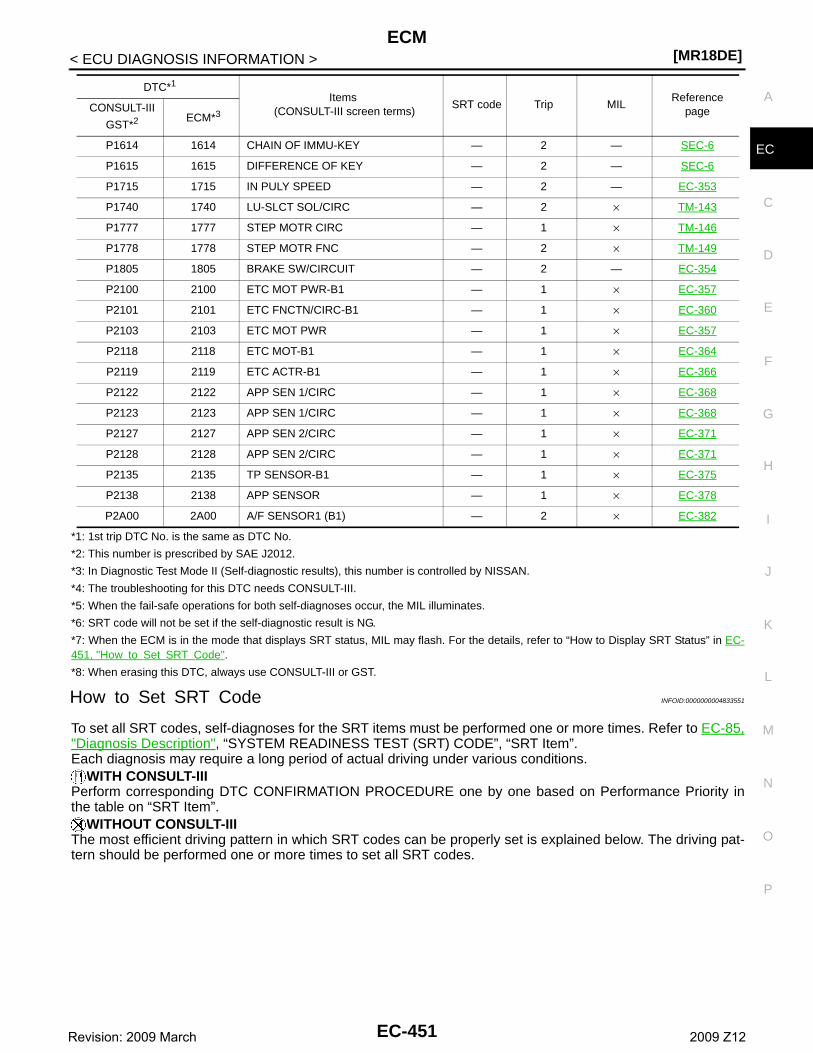
ECM[MR18DE]
C
D
E
F
G
H
I
J
K
L
M
A
C
N
P
O
< ECU DIAGNOSIS INFORMATION >
E
*1: 1st trip DTC No. is the same as DTC No.
*2: This number is prescribed by SAE J2012.
*3: In Diagnostic Test Mode II (Self-diagnostic results), this number is controlled by NISSAN.
*4: The troubleshooting for this DTC needs CONSULT-III.
*5: When the fail-safe operations for both self-diagnoses occur, the MIL illuminates.
*6: SRT code will not be set if the self-diagnostic result is NG.
*7: When the ECM is in the mode that displays SRT status, MIL may flash. For the details, refer to “How to Display SRT Status” in EC-451, "How to Set SRT Code".
*8: When erasing this DTC, always use CONSULT-III or GST.
How to Set SRT Code INFOID:0000000004833551
To set all SRT codes, self-diagnoses for the SRT items must be performed one or more times. Refer to EC-85,"Diagnosis Description", “SYSTEM READINESS TEST (SRT) CODE”, “SRT Item”.Each diagnosis may require a long period of actual driving under various conditions.
WITH CONSULT-IIIPerform corresponding DTC CONFIRMATION PROCEDURE one by one based on Performance Priority inthe table on “SRT Item”.
WITHOUT CONSULT-IIIThe most efficient driving pattern in which SRT codes can be properly set is explained below. The driving pat-tern should be performed one or more times to set all SRT codes.
P1614 1614 CHAIN OF IMMU-KEY — 2 — SEC-6
P1615 1615 DIFFERENCE OF KEY — 2 — SEC-6
P1715 1715 IN PULY SPEED — 2 — EC-353
P1740 1740 LU-SLCT SOL/CIRC — 2 × TM-143
P1777 1777 STEP MOTR CIRC — 1 × TM-146
P1778 1778 STEP MOTR FNC — 2 × TM-149
P1805 1805 BRAKE SW/CIRCUIT — 2 — EC-354
P2100 2100 ETC MOT PWR-B1 — 1 × EC-357
P2101 2101 ETC FNCTN/CIRC-B1 — 1 × EC-360
P2103 2103 ETC MOT PWR — 1 × EC-357
P2118 2118 ETC MOT-B1 — 1 × EC-364
P2119 2119 ETC ACTR-B1 — 1 × EC-366
P2122 2122 APP SEN 1/CIRC — 1 × EC-368
P2123 2123 APP SEN 1/CIRC — 1 × EC-368
P2127 2127 APP SEN 2/CIRC — 1 × EC-371
P2128 2128 APP SEN 2/CIRC — 1 × EC-371
P2135 2135 TP SENSOR-B1 — 1 × EC-375
P2138 2138 APP SENSOR — 1 × EC-378
P2A00 2A00 A/F SENSOR1 (B1) — 2 × EC-382
DTC*1
Items (CONSULT-III screen terms)
SRT code Trip MILReference
pageCONSULT-III
GST*2 ECM*3
EC-451Revision: 2009 March 2009 Z12
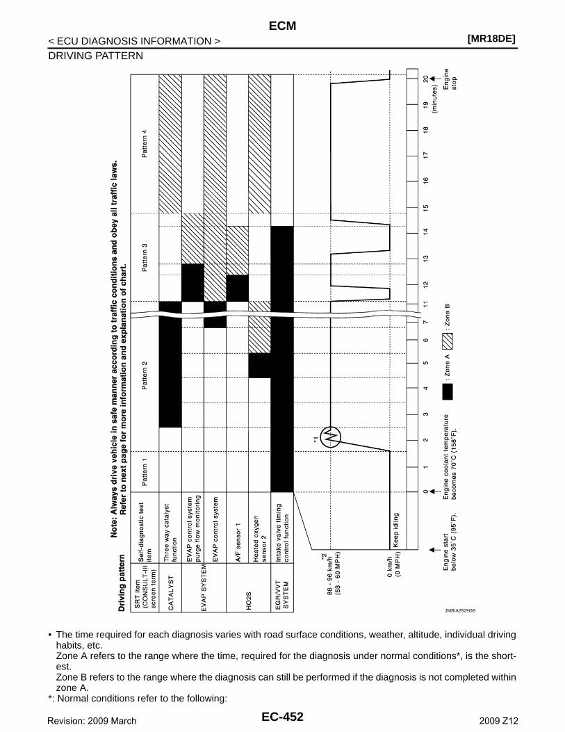
[MR18DE]ECM
< ECU DIAGNOSIS INFORMATION >
DRIVING PATTERN
• The time required for each diagnosis varies with road surface conditions, weather, altitude, individual drivinghabits, etc.Zone A refers to the range where the time, required for the diagnosis under normal conditions*, is the short-est.Zone B refers to the range where the diagnosis can still be performed if the diagnosis is not completed withinzone A.
*: Normal conditions refer to the following:
JMBIA2929GB
EC-452Revision: 2009 March 2009 Z12
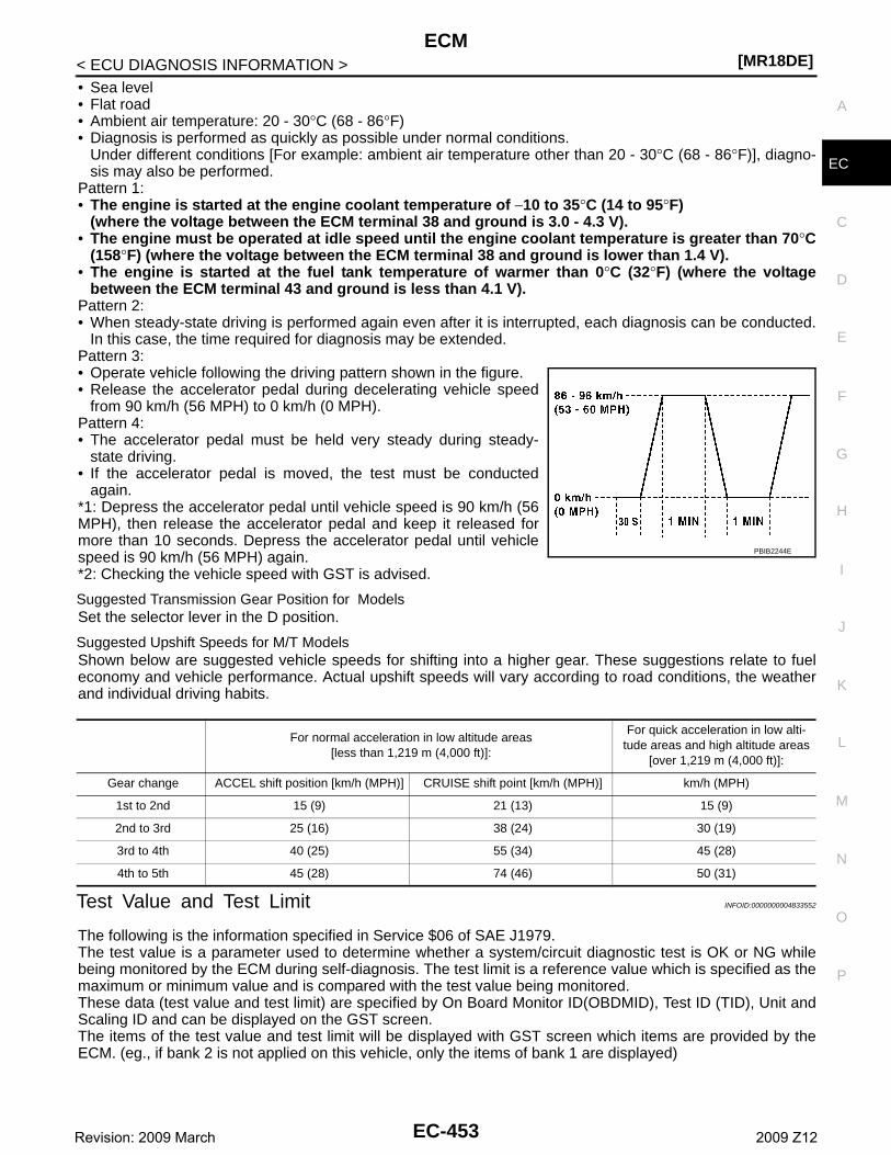
ECM[MR18DE]
C
D
E
F
G
H
I
J
K
L
M
A
C
N
P
O
< ECU DIAGNOSIS INFORMATION >
E
• Sea level• Flat road• Ambient air temperature: 20 - 30°C (68 - 86°F)• Diagnosis is performed as quickly as possible under normal conditions.
Under different conditions [For example: ambient air temperature other than 20 - 30°C (68 - 86°F)], diagno-sis may also be performed.
Pattern 1:• The engine is started at the engine coolant temperature of −10 to 35°C (14 to 95°F)
(where the voltage between the ECM terminal 38 and ground is 3.0 - 4.3 V).• The engine must be operated at idle speed until the engine coolant temperature is greater than 70°C
(158°F) (where the voltage between the ECM terminal 38 and ground is lower than 1.4 V).• The engine is started at the fuel tank temperature of warmer than 0°C (32°F) (where the voltage
between the ECM terminal 43 and ground is less than 4.1 V).Pattern 2:• When steady-state driving is performed again even after it is interrupted, each diagnosis can be conducted.
In this case, the time required for diagnosis may be extended.Pattern 3:• Operate vehicle following the driving pattern shown in the figure.• Release the accelerator pedal during decelerating vehicle speed
from 90 km/h (56 MPH) to 0 km/h (0 MPH).Pattern 4:• The accelerator pedal must be held very steady during steady-
state driving.• If the accelerator pedal is moved, the test must be conducted
again.*1: Depress the accelerator pedal until vehicle speed is 90 km/h (56MPH), then release the accelerator pedal and keep it released formore than 10 seconds. Depress the accelerator pedal until vehiclespeed is 90 km/h (56 MPH) again.*2: Checking the vehicle speed with GST is advised.
Suggested Transmission Gear Position for ModelsSet the selector lever in the D position.
Suggested Upshift Speeds for M/T ModelsShown below are suggested vehicle speeds for shifting into a higher gear. These suggestions relate to fueleconomy and vehicle performance. Actual upshift speeds will vary according to road conditions, the weatherand individual driving habits.
Test Value and Test Limit INFOID:0000000004833552
The following is the information specified in Service $06 of SAE J1979.The test value is a parameter used to determine whether a system/circuit diagnostic test is OK or NG whilebeing monitored by the ECM during self-diagnosis. The test limit is a reference value which is specified as themaximum or minimum value and is compared with the test value being monitored.These data (test value and test limit) are specified by On Board Monitor ID(OBDMID), Test ID (TID), Unit andScaling ID and can be displayed on the GST screen.The items of the test value and test limit will be displayed with GST screen which items are provided by theECM. (eg., if bank 2 is not applied on this vehicle, only the items of bank 1 are displayed)
PBIB2244E
For normal acceleration in low altitude areas[less than 1,219 m (4,000 ft)]:
For quick acceleration in low alti-tude areas and high altitude areas
[over 1,219 m (4,000 ft)]:
Gear change ACCEL shift position [km/h (MPH)] CRUISE shift point [km/h (MPH)] km/h (MPH)
1st to 2nd 15 (9) 21 (13) 15 (9)
2nd to 3rd 25 (16) 38 (24) 30 (19)
3rd to 4th 40 (25) 55 (34) 45 (28)
4th to 5th 45 (28) 74 (46) 50 (31)
EC-453Revision: 2009 March 2009 Z12
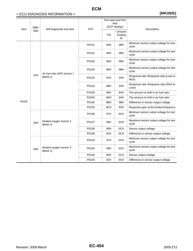
[MR18DE]ECM
< ECU DIAGNOSIS INFORMATION >
ItemOBD-MID
Self-diagnostic test item DTC
Test value and Test limit
(GST display)Description
TIDUnit and Scaling
ID
HO2S
01HAir fuel ratio (A/F) sensor 1 (Bank 1)
P0131 83H 0BHMinimum sensor output voltage for test cycle
P0131 84H 0BHMaximum sensor output voltage for test cycle
P0130 85H 0BHMinimum sensor output voltage for test cycle
P0130 86H 0BHMaximum sensor output voltage for test cycle
P0133 87H 04HResponse rate: Response ratio (Lean to Rich)
P0133 88H 04HResponse rate: Response ratio (Rich to Lean)
P2A00 89H 84H The amount of shift in air fuel ratio
P2A00 8AH 84H The amount of shift in air fuel ratio
P0130 8BH 0BH Difference in sensor output voltage
P0133 8CH 83H Response gain at the limited frequency
02HHeated oxygen sensor 2 (Bank 1)
P0138 07H 0CHMinimum sensor output voltage for test cycle
P0137 08H 0CHMaximum sensor output voltage for test cycle
P0138 80H 0CH Sensor output voltage
P0139 81H 0CH Difference in sensor output voltage
03HHeated oxygen sensor 3 (Bank 1)
P0143 07H 0CHMinimum sensor output voltage for test cycle
P0144 08H 0CHMaximum sensor output voltage for test cycle
P0146 80H 0CH Sensor output voltage
P0145 81H 0CH Difference in sensor output voltage
EC-454Revision: 2009 March 2009 Z12
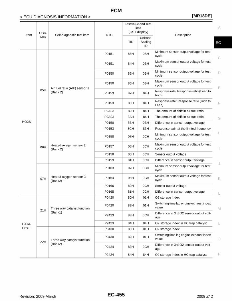
ECM[MR18DE]
C
D
E
F
G
H
I
J
K
L
M
A
C
N
P
O
< ECU DIAGNOSIS INFORMATION >
E
HO2S
05HAir fuel ratio (A/F) sensor 1 (Bank 2)
P0151 83H 0BHMinimum sensor output voltage for test cycle
P0151 84H 0BHMaximum sensor output voltage for test cycle
P0150 85H 0BHMinimum sensor output voltage for test cycle
P0150 86H 0BHMaximum sensor output voltage for test cycle
P0153 87H 04HResponse rate: Response ratio (Lean to Rich)
P0153 88H 04HResponse rate: Response ratio (Rich to Lean)
P2A03 89H 84H The amount of shift in air fuel ratio
P2A03 8AH 84H The amount of shift in air fuel ratio
P0150 8BH 0BH Difference in sensor output voltage
P0153 8CH 83H Response gain at the limited frequency
06HHeated oxygen sensor 2(Bank 2)
P0158 07H 0CHMinimum sensor output voltage for test cycle
P0157 08H 0CHMaximum sensor output voltage for test cycle
P0158 80H 0CH Sensor output voltage
P0159 81H 0CH Difference in sensor output voltage
07HHeated oxygen sensor 3 (Bank2)
P0163 07H 0CHMinimum sensor output voltage for test cycle
P0164 08H 0CHMaximum sensor output voltage for test cycle
P0166 80H 0CH Sensor output voltage
P0165 81H 0CH Difference in sensor output voltage
CATA-LYST
21HThree way catalyst function (Bank1)
P0420 80H 01H O2 storage index
P0420 82H 01HSwitching time lag engine exhaust index value
P2423 83H 0CHDifference in 3rd O2 sensor output volt-age
P2423 84H 84H O2 storage index in HC trap catalyst
22HThree way catalyst function (Bank2)
P0430 80H 01H O2 storage index
P0430 82H 01HSwitching time lag engine exhaust index value
P2424 83H 0CHDifference in 3rd O2 sensor output volt-age
P2424 84H 84H O2 storage index in HC trap catalyst
ItemOBD-MID
Self-diagnostic test item DTC
Test value and Test limit
(GST display)Description
TIDUnit and Scaling
ID
EC-455Revision: 2009 March 2009 Z12
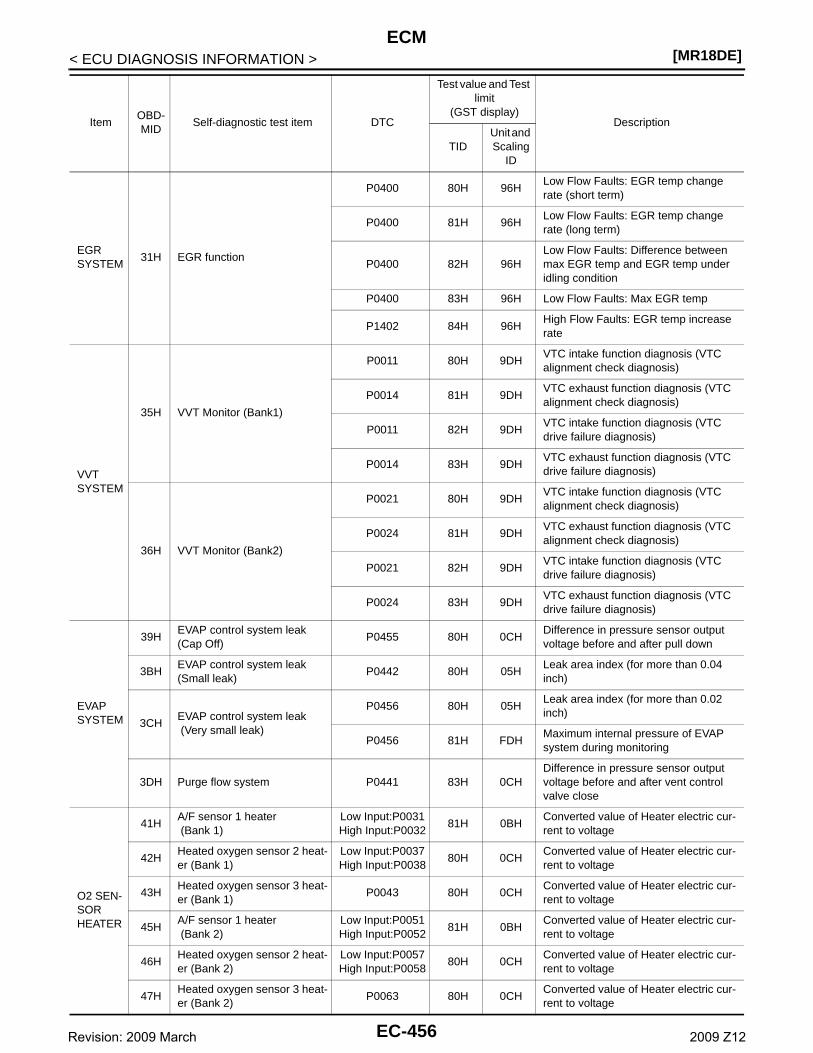
[MR18DE]ECM
< ECU DIAGNOSIS INFORMATION >
EGR SYSTEM
31H EGR function
P0400 80H 96HLow Flow Faults: EGR temp change rate (short term)
P0400 81H 96HLow Flow Faults: EGR temp change rate (long term)
P0400 82H 96HLow Flow Faults: Difference between max EGR temp and EGR temp under idling condition
P0400 83H 96H Low Flow Faults: Max EGR temp
P1402 84H 96HHigh Flow Faults: EGR temp increase rate
VVT SYSTEM
35H VVT Monitor (Bank1)
P0011 80H 9DHVTC intake function diagnosis (VTC alignment check diagnosis)
P0014 81H 9DHVTC exhaust function diagnosis (VTC alignment check diagnosis)
P0011 82H 9DHVTC intake function diagnosis (VTC drive failure diagnosis)
P0014 83H 9DHVTC exhaust function diagnosis (VTC drive failure diagnosis)
36H VVT Monitor (Bank2)
P0021 80H 9DHVTC intake function diagnosis (VTC alignment check diagnosis)
P0024 81H 9DHVTC exhaust function diagnosis (VTC alignment check diagnosis)
P0021 82H 9DHVTC intake function diagnosis (VTC drive failure diagnosis)
P0024 83H 9DHVTC exhaust function diagnosis (VTC drive failure diagnosis)
EVAP SYSTEM
39HEVAP control system leak (Cap Off)
P0455 80H 0CHDifference in pressure sensor output voltage before and after pull down
3BHEVAP control system leak (Small leak)
P0442 80H 05HLeak area index (for more than 0.04 inch)
3CHEVAP control system leak (Very small leak)
P0456 80H 05HLeak area index (for more than 0.02 inch)
P0456 81H FDHMaximum internal pressure of EVAP system during monitoring
3DH Purge flow system P0441 83H 0CHDifference in pressure sensor output voltage before and after vent control valve close
O2 SEN-SOR HEATER
41HA/F sensor 1 heater (Bank 1)
Low Input:P0031High Input:P0032
81H 0BHConverted value of Heater electric cur-rent to voltage
42HHeated oxygen sensor 2 heat-er (Bank 1)
Low Input:P0037High Input:P0038
80H 0CHConverted value of Heater electric cur-rent to voltage
43HHeated oxygen sensor 3 heat-er (Bank 1)
P0043 80H 0CHConverted value of Heater electric cur-rent to voltage
45HA/F sensor 1 heater (Bank 2)
Low Input:P0051High Input:P0052
81H 0BHConverted value of Heater electric cur-rent to voltage
46HHeated oxygen sensor 2 heat-er (Bank 2)
Low Input:P0057High Input:P0058
80H 0CHConverted value of Heater electric cur-rent to voltage
47HHeated oxygen sensor 3 heat-er (Bank 2)
P0063 80H 0CHConverted value of Heater electric cur-rent to voltage
ItemOBD-MID
Self-diagnostic test item DTC
Test value and Test limit
(GST display)Description
TIDUnit and Scaling
ID
EC-456Revision: 2009 March 2009 Z12
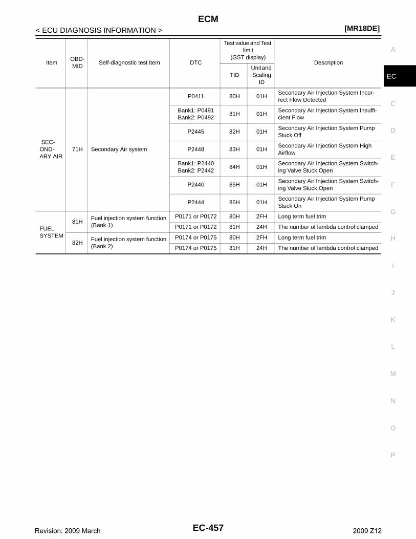
ECM[MR18DE]
C
D
E
F
G
H
I
J
K
L
M
A
C
N
P
O
< ECU DIAGNOSIS INFORMATION >
E
SEC-OND-ARY AIR
71H Secondary Air system
P0411 80H 01HSecondary Air Injection System Incor-rect Flow Detected
Bank1: P0491Bank2: P0492
81H 01HSecondary Air Injection System Insuffi-cient Flow
P2445 82H 01HSecondary Air Injection System Pump Stuck Off
P2448 83H 01HSecondary Air Injection System High Airflow
Bank1: P2440Bank2: P2442
84H 01HSecondary Air Injection System Switch-ing Valve Stuck Open
P2440 85H 01HSecondary Air Injection System Switch-ing Valve Stuck Open
P2444 86H 01HSecondary Air Injection System Pump Stuck On
FUEL SYSTEM
81HFuel injection system function (Bank 1)
P0171 or P0172 80H 2FH Long term fuel trim
P0171 or P0172 81H 24H The number of lambda control clamped
82HFuel injection system function (Bank 2)
P0174 or P0175 80H 2FH Long term fuel trim
P0174 or P0175 81H 24H The number of lambda control clamped
ItemOBD-MID
Self-diagnostic test item DTC
Test value and Test limit
(GST display)Description
TIDUnit and Scaling
ID
EC-457Revision: 2009 March 2009 Z12
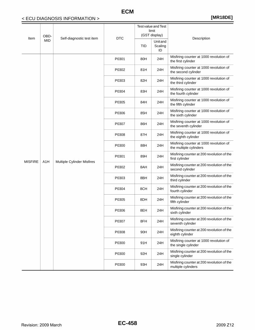
[MR18DE]ECM
< ECU DIAGNOSIS INFORMATION >
MISFIRE A1H Multiple Cylinder Misfires
P0301 80H 24HMisfiring counter at 1000 revolution of the first cylinder
P0302 81H 24HMisfiring counter at 1000 revolution of the second cylinder
P0303 82H 24HMisfiring counter at 1000 revolution of the third cylinder
P0304 83H 24HMisfiring counter at 1000 revolution of the fourth cylinder
P0305 84H 24HMisfiring counter at 1000 revolution of the fifth cylinder
P0306 85H 24HMisfiring counter at 1000 revolution of the sixth cylinder
P0307 86H 24HMisfiring counter at 1000 revolution of the seventh cylinder
P0308 87H 24HMisfiring counter at 1000 revolution of the eighth cylinder
P0300 88H 24HMisfiring counter at 1000 revolution of the multiple cylinders
P0301 89H 24HMisfiring counter at 200 revolution of the first cylinder
P0302 8AH 24HMisfiring counter at 200 revolution of the second cylinder
P0303 8BH 24HMisfiring counter at 200 revolution of the third cylinder
P0304 8CH 24HMisfiring counter at 200 revolution of the fourth cylinder
P0305 8DH 24HMisfiring counter at 200 revolution of the fifth cylinder
P0306 8EH 24HMisfiring counter at 200 revolution of the sixth cylinder
P0307 8FH 24HMisfiring counter at 200 revolution of the seventh cylinder
P0308 90H 24HMisfiring counter at 200 revolution of the eighth cylinder
P0300 91H 24HMisfiring counter at 1000 revolution of the single cylinder
P0300 92H 24HMisfiring counter at 200 revolution of the single cylinder
P0300 93H 24HMisfiring counter at 200 revolution of the multiple cylinders
ItemOBD-MID
Self-diagnostic test item DTC
Test value and Test limit
(GST display)Description
TIDUnit and Scaling
ID
EC-458Revision: 2009 March 2009 Z12
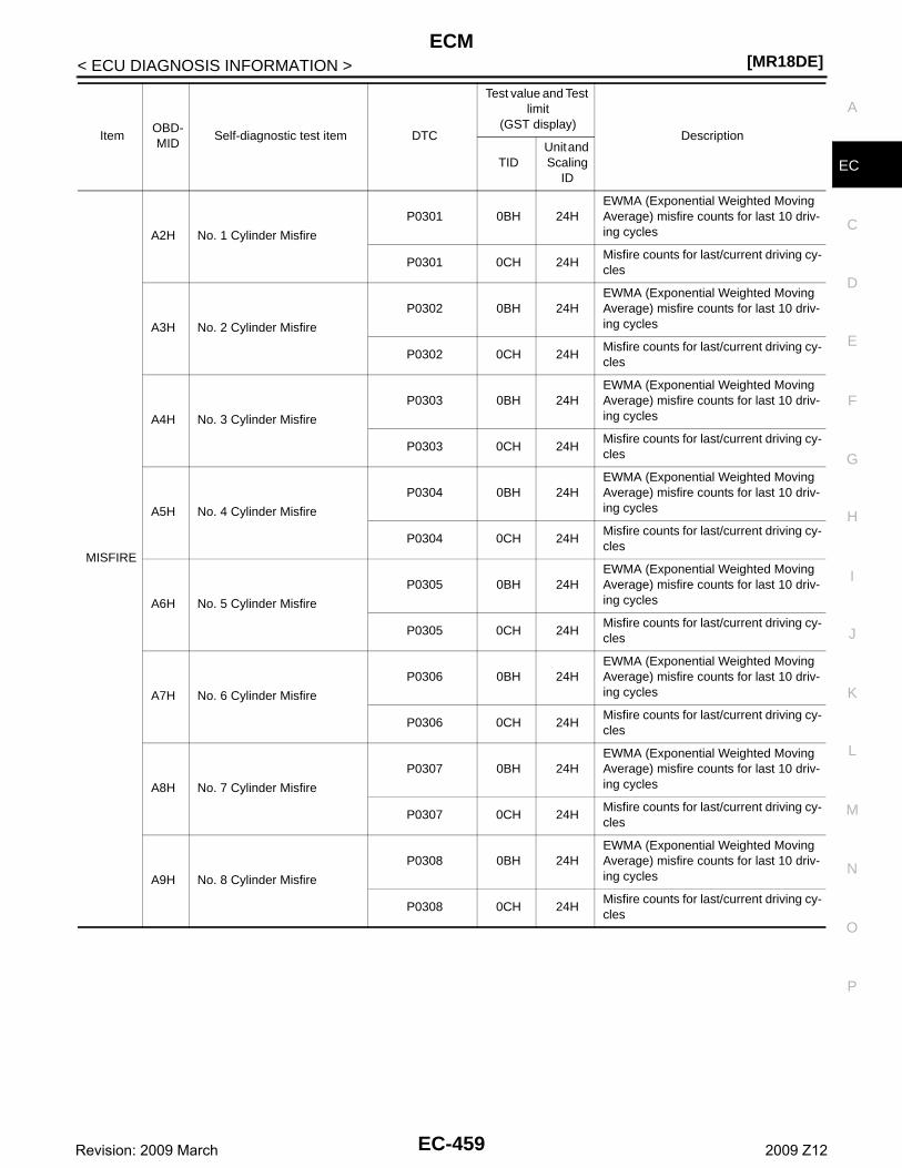
ECM[MR18DE]
C
D
E
F
G
H
I
J
K
L
M
A
C
N
P
O
< ECU DIAGNOSIS INFORMATION >
E
MISFIRE
A2H No. 1 Cylinder Misfire
P0301 0BH 24HEWMA (Exponential Weighted Moving Average) misfire counts for last 10 driv-ing cycles
P0301 0CH 24HMisfire counts for last/current driving cy-cles
A3H No. 2 Cylinder Misfire
P0302 0BH 24HEWMA (Exponential Weighted Moving Average) misfire counts for last 10 driv-ing cycles
P0302 0CH 24HMisfire counts for last/current driving cy-cles
A4H No. 3 Cylinder Misfire
P0303 0BH 24HEWMA (Exponential Weighted Moving Average) misfire counts for last 10 driv-ing cycles
P0303 0CH 24HMisfire counts for last/current driving cy-cles
A5H No. 4 Cylinder Misfire
P0304 0BH 24HEWMA (Exponential Weighted Moving Average) misfire counts for last 10 driv-ing cycles
P0304 0CH 24HMisfire counts for last/current driving cy-cles
A6H No. 5 Cylinder Misfire
P0305 0BH 24HEWMA (Exponential Weighted Moving Average) misfire counts for last 10 driv-ing cycles
P0305 0CH 24HMisfire counts for last/current driving cy-cles
A7H No. 6 Cylinder Misfire
P0306 0BH 24HEWMA (Exponential Weighted Moving Average) misfire counts for last 10 driv-ing cycles
P0306 0CH 24HMisfire counts for last/current driving cy-cles
A8H No. 7 Cylinder Misfire
P0307 0BH 24HEWMA (Exponential Weighted Moving Average) misfire counts for last 10 driv-ing cycles
P0307 0CH 24HMisfire counts for last/current driving cy-cles
A9H No. 8 Cylinder Misfire
P0308 0BH 24HEWMA (Exponential Weighted Moving Average) misfire counts for last 10 driv-ing cycles
P0308 0CH 24HMisfire counts for last/current driving cy-cles
ItemOBD-MID
Self-diagnostic test item DTC
Test value and Test limit
(GST display)Description
TIDUnit and Scaling
ID
EC-459Revision: 2009 March 2009 Z12
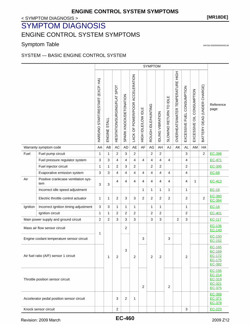
[MR18DE]ENGINE CONTROL SYSTEM SYMPTOMS
< SYMPTOM DIAGNOSIS >
SYMPTOM DIAGNOSISENGINE CONTROL SYSTEM SYMPTOMS
Symptom Table INFOID:0000000005040146
SYSTEM — BASIC ENGINE CONTROL SYSTEM
SYMPTOM
Reference page
HA
RD
/NO
STA
RT
/RE
STA
RT
(E
XC
P. H
A)
EN
GIN
E S
TALL
HE
SIT
AT
ION
/SU
RG
ING
/FLA
T S
PO
T
SP
AR
K K
NO
CK
/DE
TO
NA
TIO
N
LAC
K O
F P
OW
ER
/PO
OR
AC
CE
LER
AT
ION
HIG
H ID
LE/L
OW
IDLE
RO
UG
H ID
LE/H
UN
TIN
G
IDLI
NG
VIB
RA
TIO
N
SLO
W/N
O R
ET
UR
N T
O ID
LE
OV
ER
HE
AT
S/W
AT
ER
TE
MP
ER
AT
UR
E H
IGH
EX
CE
SS
IVE
FU
EL
CO
NS
UM
PT
ION
EX
CE
SS
IVE
OIL
CO
NS
UM
PT
ION
BA
TT
ER
Y D
EA
D (
UN
DE
R C
HA
RG
E)
Warranty symptom code AA AB AC AD AE AF AG AH AJ AK AL AM HA
Fuel Fuel pump circuit 1 1 2 3 2 2 2 3 2 EC-398
Fuel pressure regulator system 3 3 4 4 4 4 4 4 4 4 EC-471
Fuel injector circuit 1 1 2 3 2 2 2 2 EC-395
Evaporative emission system 3 3 4 4 4 4 4 4 4 4 EC-68
Air Positive crankcase ventilation sys-tem 3 3
4 4 4 4 4 4 4 4 1 EC-413
Incorrect idle speed adjustment 1 1 1 1 1 EC-16
Electric throttle control actuator 1 1 2 3 3 2 2 2 2 2 2EC-360EC-364
Ignition Incorrect ignition timing adjustment 3 3 1 1 1 1 1 1 EC-16
Ignition circuit 1 1 2 2 2 2 2 2 EC-401
Main power supply and ground circuit 2 2 3 3 3 3 3 2 3 EC-117
Mass air flow sensor circuit
1
1 2
2
2 2 2 2
EC-136EC-143
Engine coolant temperature sensor circuit
3
3 3EC-150EC-152
Air fuel ratio (A/F) sensor 1 circuit
EC-165EC-169EC-172EC-175EC-382
Throttle position sensor circuit
2 2
EC-155EC-214EC-319EC-321EC-375
Accelerator pedal position sensor circuit 3 2 1EC-368EC-371EC-378
Knock sensor circuit 2 3 EC-223
EC-460Revision: 2009 March 2009 Z12
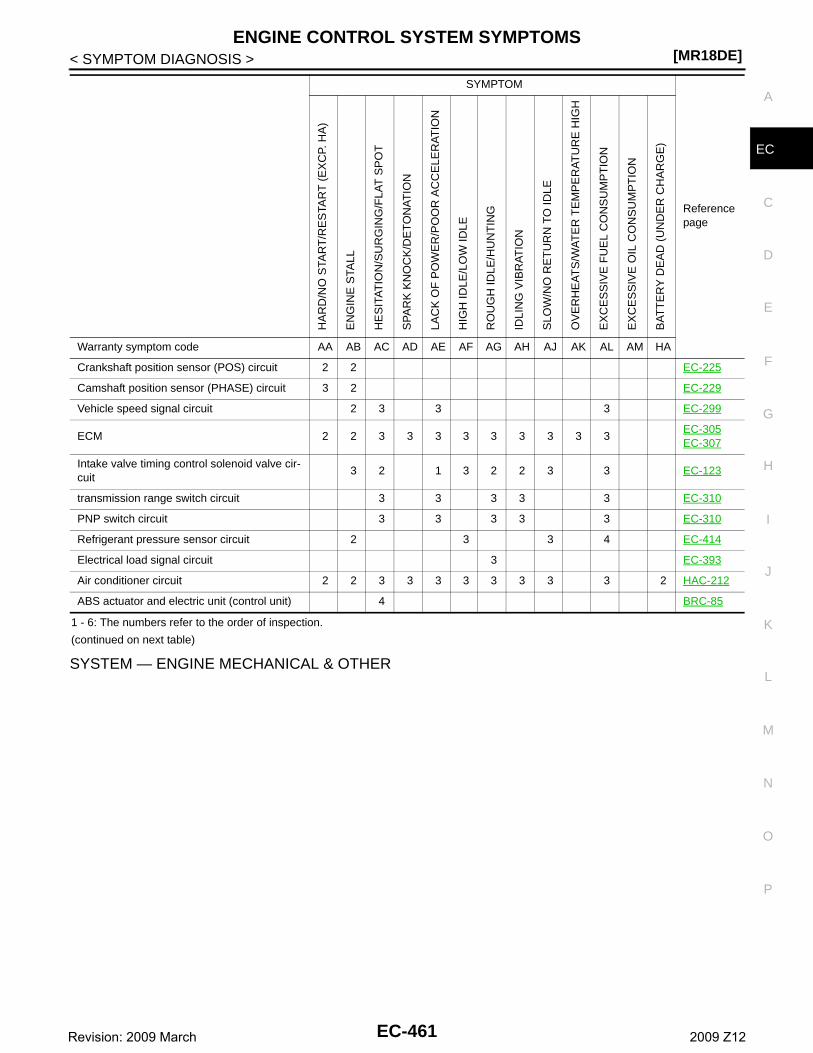
ENGINE CONTROL SYSTEM SYMPTOMS[MR18DE]
C
D
E
F
G
H
I
J
K
L
M
A
C
N
P
O
< SYMPTOM DIAGNOSIS >
E
1 - 6: The numbers refer to the order of inspection.
(continued on next table)
SYSTEM — ENGINE MECHANICAL & OTHER
Crankshaft position sensor (POS) circuit 2 2 EC-225
Camshaft position sensor (PHASE) circuit 3 2 EC-229
Vehicle speed signal circuit 2 3 3 3 EC-299
ECM 2 2 3 3 3 3 3 3 3 3 3EC-305EC-307
Intake valve timing control solenoid valve cir-cuit
3 2 1 3 2 2 3 3 EC-123
transmission range switch circuit 3 3 3 3 3 EC-310
PNP switch circuit 3 3 3 3 3 EC-310
Refrigerant pressure sensor circuit 2 3 3 4 EC-414
Electrical load signal circuit 3 EC-393
Air conditioner circuit 2 2 3 3 3 3 3 3 3 3 2 HAC-212
ABS actuator and electric unit (control unit) 4 BRC-85
SYMPTOM
Reference page
HA
RD
/NO
STA
RT
/RE
STA
RT
(E
XC
P. H
A)
EN
GIN
E S
TALL
HE
SIT
AT
ION
/SU
RG
ING
/FLA
T S
PO
T
SP
AR
K K
NO
CK
/DE
TO
NA
TIO
N
LAC
K O
F P
OW
ER
/PO
OR
AC
CE
LER
AT
ION
HIG
H ID
LE/L
OW
IDLE
RO
UG
H ID
LE/H
UN
TIN
G
IDLI
NG
VIB
RA
TIO
N
SLO
W/N
O R
ET
UR
N T
O ID
LE
OV
ER
HE
AT
S/W
AT
ER
TE
MP
ER
AT
UR
E H
IGH
EX
CE
SS
IVE
FU
EL
CO
NS
UM
PT
ION
EX
CE
SS
IVE
OIL
CO
NS
UM
PT
ION
BA
TT
ER
Y D
EA
D (
UN
DE
R C
HA
RG
E)
Warranty symptom code AA AB AC AD AE AF AG AH AJ AK AL AM HA
EC-461Revision: 2009 March 2009 Z12
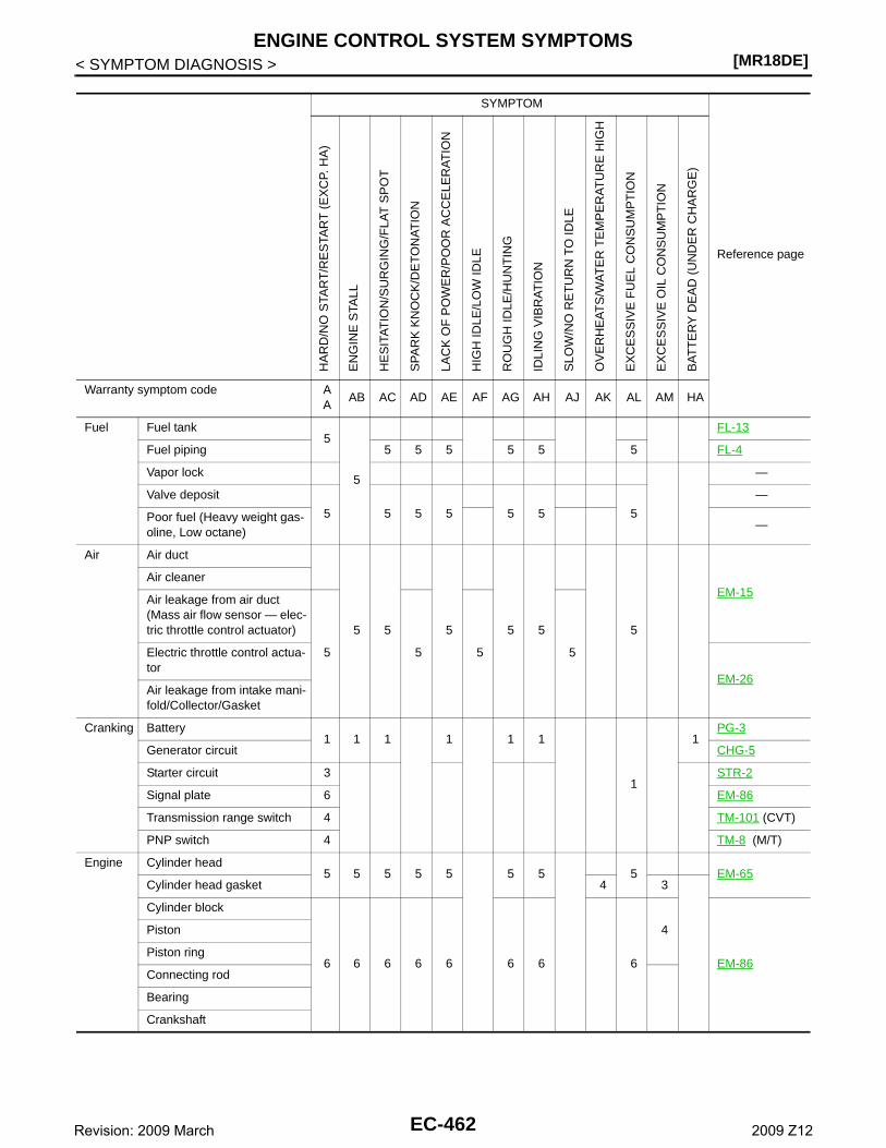
[MR18DE]ENGINE CONTROL SYSTEM SYMPTOMS
< SYMPTOM DIAGNOSIS >
SYMPTOM
Reference page
HA
RD
/NO
STA
RT
/RE
STA
RT
(E
XC
P. H
A)
EN
GIN
E S
TALL
HE
SIT
AT
ION
/SU
RG
ING
/FLA
T S
PO
T
SP
AR
K K
NO
CK
/DE
TO
NA
TIO
N
LAC
K O
F P
OW
ER
/PO
OR
AC
CE
LER
AT
ION
HIG
H ID
LE/L
OW
IDLE
RO
UG
H ID
LE/H
UN
TIN
G
IDLI
NG
VIB
RA
TIO
N
SLO
W/N
O R
ET
UR
N T
O ID
LE
OV
ER
HE
AT
S/W
AT
ER
TE
MP
ER
AT
UR
E H
IGH
EX
CE
SS
IVE
FU
EL
CO
NS
UM
PT
ION
EX
CE
SS
IVE
OIL
CO
NS
UM
PT
ION
BA
TT
ER
Y D
EA
D (
UN
DE
R C
HA
RG
E)
Warranty symptom code AA
AB AC AD AE AF AG AH AJ AK AL AM HA
Fuel Fuel tank5
5
FL-13
Fuel piping 5 5 5 5 5 5 FL-4
Vapor lock —
Valve deposit
5 5 5 5 5 5 5
—
Poor fuel (Heavy weight gas-oline, Low octane)
—
Air Air duct
5 5 5 5 5 5
EM-15Air cleaner
Air leakage from air duct(Mass air flow sensor — elec-tric throttle control actuator)
5 5 5 5Electric throttle control actua-tor
EM-26Air leakage from intake mani-fold/Collector/Gasket
Cranking Battery1 1 1 1 1 1
1
1PG-3
Generator circuit CHG-5
Starter circuit 3 STR-2
Signal plate 6 EM-86
Transmission range switch 4 TM-101 (CVT)
PNP switch 4 TM-8 (M/T)
Engine Cylinder head5 5 5 5 5 5 5 5 EM-65
Cylinder head gasket 4 3
Cylinder block
6 6 6 6 6 6 6 6
4
EM-86
Piston
Piston ring
Connecting rod
Bearing
Crankshaft
EC-462Revision: 2009 March 2009 Z12
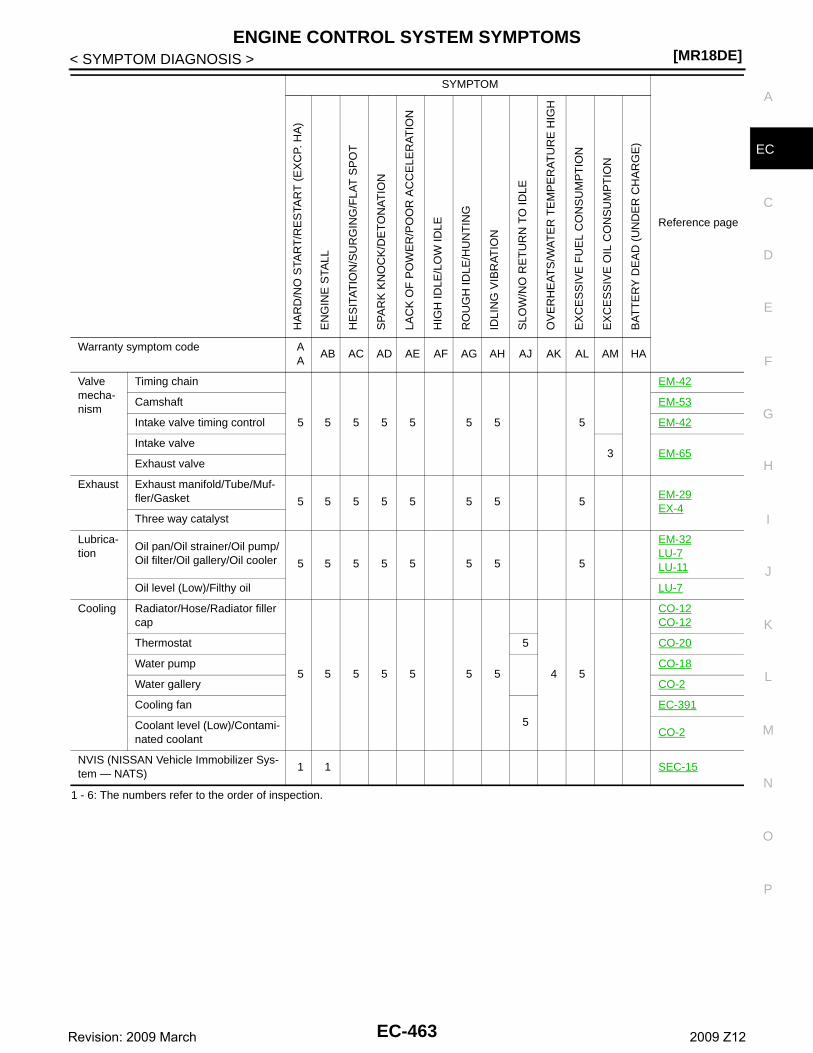
ENGINE CONTROL SYSTEM SYMPTOMS[MR18DE]
C
D
E
F
G
H
I
J
K
L
M
A
C
N
P
O
< SYMPTOM DIAGNOSIS >
E
1 - 6: The numbers refer to the order of inspection.
Valve mecha-nism
Timing chain
5 5 5 5 5 5 5 5
EM-42
Camshaft EM-53
Intake valve timing control EM-42
Intake valve3 EM-65
Exhaust valve
Exhaust Exhaust manifold/Tube/Muf-fler/Gasket 5 5 5 5 5 5 5 5
EM-29EX-4
Three way catalyst
Lubrica-tion
Oil pan/Oil strainer/Oil pump/Oil filter/Oil gallery/Oil cooler 5 5 5 5 5 5 5 5
EM-32LU-7LU-11
Oil level (Low)/Filthy oil LU-7
Cooling Radiator/Hose/Radiator filler cap
5 5 5 5 5 5 5 4 5
CO-12CO-12
Thermostat 5 CO-20
Water pump CO-18
Water gallery CO-2
Cooling fan
5
EC-391
Coolant level (Low)/Contami-nated coolant
CO-2
NVIS (NISSAN Vehicle Immobilizer Sys-tem — NATS)
1 1 SEC-15
SYMPTOM
Reference page
HA
RD
/NO
STA
RT
/RE
STA
RT
(E
XC
P. H
A)
EN
GIN
E S
TALL
HE
SIT
AT
ION
/SU
RG
ING
/FLA
T S
PO
T
SP
AR
K K
NO
CK
/DE
TO
NA
TIO
N
LAC
K O
F P
OW
ER
/PO
OR
AC
CE
LER
AT
ION
HIG
H ID
LE/L
OW
IDLE
RO
UG
H ID
LE/H
UN
TIN
G
IDLI
NG
VIB
RA
TIO
N
SLO
W/N
O R
ET
UR
N T
O ID
LE
OV
ER
HE
AT
S/W
AT
ER
TE
MP
ER
AT
UR
E H
IGH
EX
CE
SS
IVE
FU
EL
CO
NS
UM
PT
ION
EX
CE
SS
IVE
OIL
CO
NS
UM
PT
ION
BA
TT
ER
Y D
EA
D (
UN
DE
R C
HA
RG
E)
Warranty symptom code AA
AB AC AD AE AF AG AH AJ AK AL AM HA
EC-463Revision: 2009 March 2009 Z12
[MR18DE]NORMAL OPERATING CONDITION
< SYMPTOM DIAGNOSIS >
NORMAL OPERATING CONDITION
Description INFOID:0000000004833554
FUEL CUT CONTROL (AT NO LOAD AND HIGH ENGINE SPEED)If the engine speed is above 2,500 rpm under no load (for example, the selector lever position is neutral andengine speed is over 2,500 rpm) fuel will be cut off after some time. The exact time when the fuel is cut off var-ies based on engine speed.Fuel cut will be operated until the engine speed reaches 2,000 rpm, then fuel cut will be cancelled.NOTE:This function is different from deceleration control listed under Multiport Fuel Injection (MFI) System, EC-28,"System Description".
EC-464Revision: 2009 March 2009 Z12
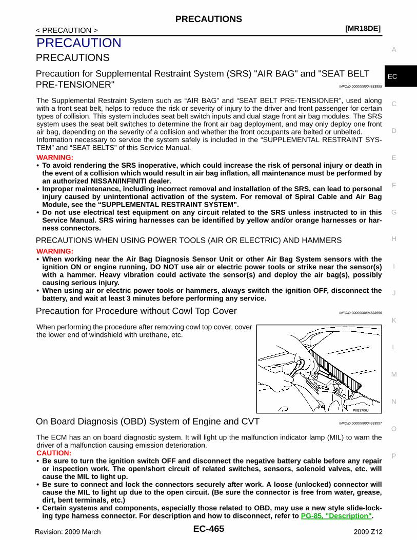
PRECAUTIONS[MR18DE]
C
D
E
F
G
H
I
J
K
L
M
A
C
N
P
O
< PRECAUTION >
E
PRECAUTIONPRECAUTIONS
Precaution for Supplemental Restraint System (SRS) "AIR BAG" and "SEAT BELT PRE-TENSIONER" INFOID:0000000004833555
The Supplemental Restraint System such as “AIR BAG” and “SEAT BELT PRE-TENSIONER”, used alongwith a front seat belt, helps to reduce the risk or severity of injury to the driver and front passenger for certaintypes of collision. This system includes seat belt switch inputs and dual stage front air bag modules. The SRSsystem uses the seat belt switches to determine the front air bag deployment, and may only deploy one frontair bag, depending on the severity of a collision and whether the front occupants are belted or unbelted.Information necessary to service the system safely is included in the “SUPPLEMENTAL RESTRAINT SYS-TEM” and “SEAT BELTS” of this Service Manual.WARNING:• To avoid rendering the SRS inoperative, which could increase the risk of personal injury or death in
the event of a collision which would result in air bag inflation, all maintenance must be performed byan authorized NISSAN/INFINITI dealer.
• Improper maintenance, including incorrect removal and installation of the SRS, can lead to personalinjury caused by unintentional activation of the system. For removal of Spiral Cable and Air BagModule, see the “SUPPLEMENTAL RESTRAINT SYSTEM”.
• Do not use electrical test equipment on any circuit related to the SRS unless instructed to in thisService Manual. SRS wiring harnesses can be identified by yellow and/or orange harnesses or har-ness connectors.
PRECAUTIONS WHEN USING POWER TOOLS (AIR OR ELECTRIC) AND HAMMERSWARNING:• When working near the Air Bag Diagnosis Sensor Unit or other Air Bag System sensors with the
ignition ON or engine running, DO NOT use air or electric power tools or strike near the sensor(s)with a hammer. Heavy vibration could activate the sensor(s) and deploy the air bag(s), possiblycausing serious injury.
• When using air or electric power tools or hammers, always switch the ignition OFF, disconnect thebattery, and wait at least 3 minutes before performing any service.
Precaution for Procedure without Cowl Top Cover INFOID:0000000004833556
When performing the procedure after removing cowl top cover, coverthe lower end of windshield with urethane, etc.
On Board Diagnosis (OBD) System of Engine and CVT INFOID:0000000004833557
The ECM has an on board diagnostic system. It will light up the malfunction indicator lamp (MIL) to warn thedriver of a malfunction causing emission deterioration.CAUTION:• Be sure to turn the ignition switch OFF and disconnect the negative battery cable before any repair
or inspection work. The open/short circuit of related switches, sensors, solenoid valves, etc. willcause the MIL to light up.
• Be sure to connect and lock the connectors securely after work. A loose (unlocked) connector willcause the MIL to light up due to the open circuit. (Be sure the connector is free from water, grease,dirt, bent terminals, etc.)
• Certain systems and components, especially those related to OBD, may use a new style slide-lock-ing type harness connector. For description and how to disconnect, refer to PG-85, "Description".
PIIB3706J
EC-465Revision: 2009 March 2009 Z12
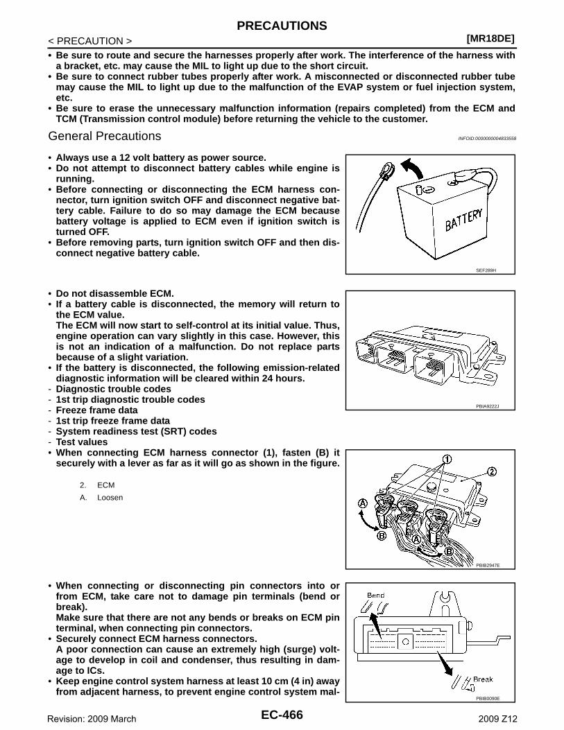
[MR18DE]PRECAUTIONS
< PRECAUTION >• Be sure to route and secure the harnesses properly after work. The interference of the harness with
a bracket, etc. may cause the MIL to light up due to the short circuit.• Be sure to connect rubber tubes properly after work. A misconnected or disconnected rubber tube
may cause the MIL to light up due to the malfunction of the EVAP system or fuel injection system,etc.
• Be sure to erase the unnecessary malfunction information (repairs completed) from the ECM andTCM (Transmission control module) before returning the vehicle to the customer.
General Precautions INFOID:0000000004833558
• Always use a 12 volt battery as power source.• Do not attempt to disconnect battery cables while engine is
running.• Before connecting or disconnecting the ECM harness con-
nector, turn ignition switch OFF and disconnect negative bat-tery cable. Failure to do so may damage the ECM becausebattery voltage is applied to ECM even if ignition switch isturned OFF.
• Before removing parts, turn ignition switch OFF and then dis-connect negative battery cable.
• Do not disassemble ECM.• If a battery cable is disconnected, the memory will return to
the ECM value.The ECM will now start to self-control at its initial value. Thus,engine operation can vary slightly in this case. However, thisis not an indication of a malfunction. Do not replace partsbecause of a slight variation.
• If the battery is disconnected, the following emission-relateddiagnostic information will be cleared within 24 hours.
- Diagnostic trouble codes- 1st trip diagnostic trouble codes- Freeze frame data- 1st trip freeze frame data- System readiness test (SRT) codes- Test values• When connecting ECM harness connector (1), fasten (B) it
securely with a lever as far as it will go as shown in the figure.
• When connecting or disconnecting pin connectors into orfrom ECM, take care not to damage pin terminals (bend orbreak).Make sure that there are not any bends or breaks on ECM pinterminal, when connecting pin connectors.
• Securely connect ECM harness connectors.A poor connection can cause an extremely high (surge) volt-age to develop in coil and condenser, thus resulting in dam-age to ICs.
• Keep engine control system harness at least 10 cm (4 in) awayfrom adjacent harness, to prevent engine control system mal-
SEF289H
2. ECM
A. Loosen
PBIA9222J
PBIB2947E
PBIB0090E
EC-466Revision: 2009 March 2009 Z12
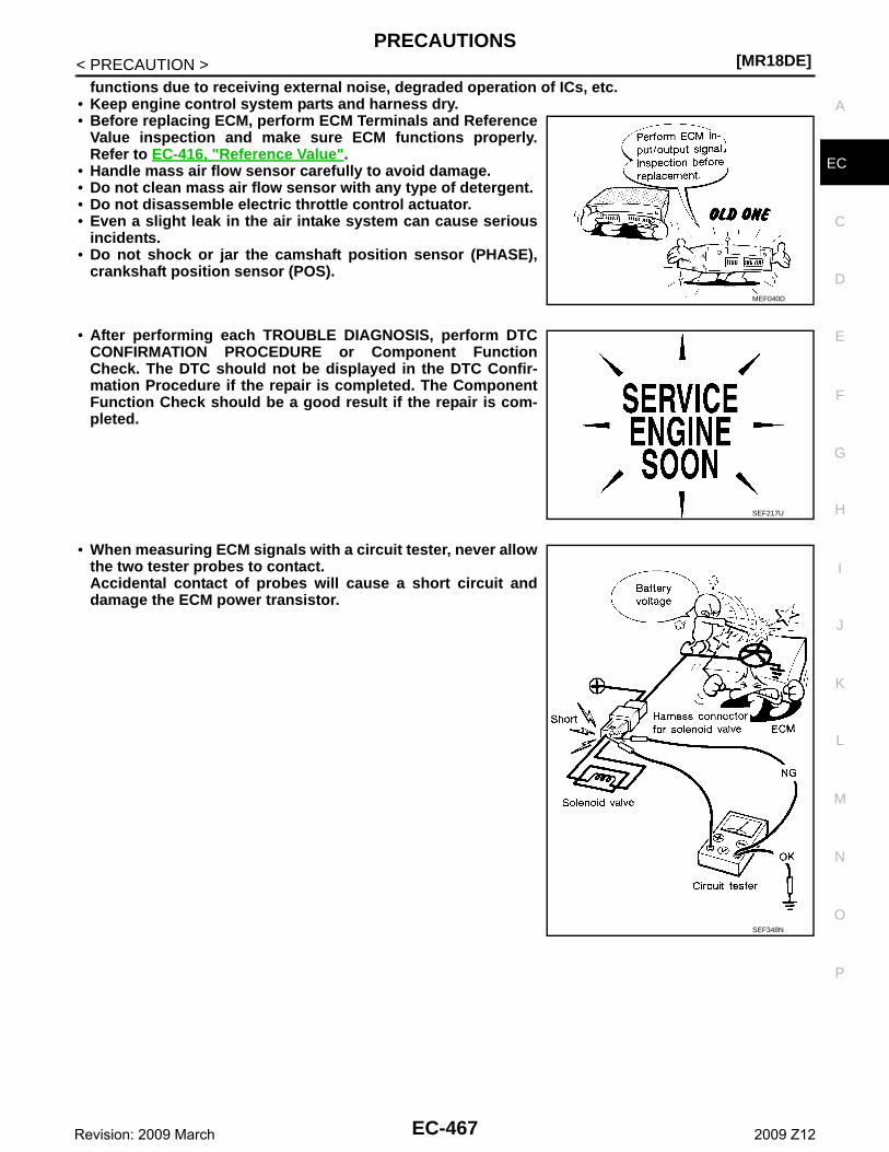
PRECAUTIONS[MR18DE]
C
D
E
F
G
H
I
J
K
L
M
A
C
N
P
O
< PRECAUTION >
E
functions due to receiving external noise, degraded operation of ICs, etc.• Keep engine control system parts and harness dry.• Before replacing ECM, perform ECM Terminals and Reference
Value inspection and make sure ECM functions properly.Refer to EC-416, "Reference Value".
• Handle mass air flow sensor carefully to avoid damage.• Do not clean mass air flow sensor with any type of detergent.• Do not disassemble electric throttle control actuator.• Even a slight leak in the air intake system can cause serious
incidents.• Do not shock or jar the camshaft position sensor (PHASE),
crankshaft position sensor (POS).
• After performing each TROUBLE DIAGNOSIS, perform DTCCONFIRMATION PROCEDURE or Component FunctionCheck. The DTC should not be displayed in the DTC Confir-mation Procedure if the repair is completed. The ComponentFunction Check should be a good result if the repair is com-pleted.
• When measuring ECM signals with a circuit tester, never allowthe two tester probes to contact.Accidental contact of probes will cause a short circuit anddamage the ECM power transistor.
MEF040D
SEF217U
SEF348N
EC-467Revision: 2009 March 2009 Z12
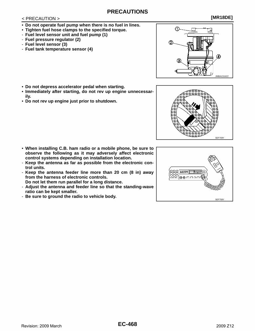
[MR18DE]PRECAUTIONS
< PRECAUTION >• Do not operate fuel pump when there is no fuel in lines.• Tighten fuel hose clamps to the specified torque.- Fuel level sensor unit and fuel pump (1)- Fuel pressure regulator (2)- Fuel level sensor (3)- Fuel tank temperature sensor (4)
• Do not depress accelerator pedal when starting.• Immediately after starting, do not rev up engine unnecessar-
ily.• Do not rev up engine just prior to shutdown.
• When installing C.B. ham radio or a mobile phone, be sure toobserve the following as it may adversely affect electroniccontrol systems depending on installation location.
- Keep the antenna as far as possible from the electronic con-trol units.
- Keep the antenna feeder line more than 20 cm (8 in) awayfrom the harness of electronic controls.Do not let them run parallel for a long distance.
- Adjust the antenna and feeder line so that the standing-waveratio can be kept smaller.
- Be sure to ground the radio to vehicle body.
JMBIA2316ZZ
SEF709Y
SEF708Y
EC-468Revision: 2009 March 2009 Z12
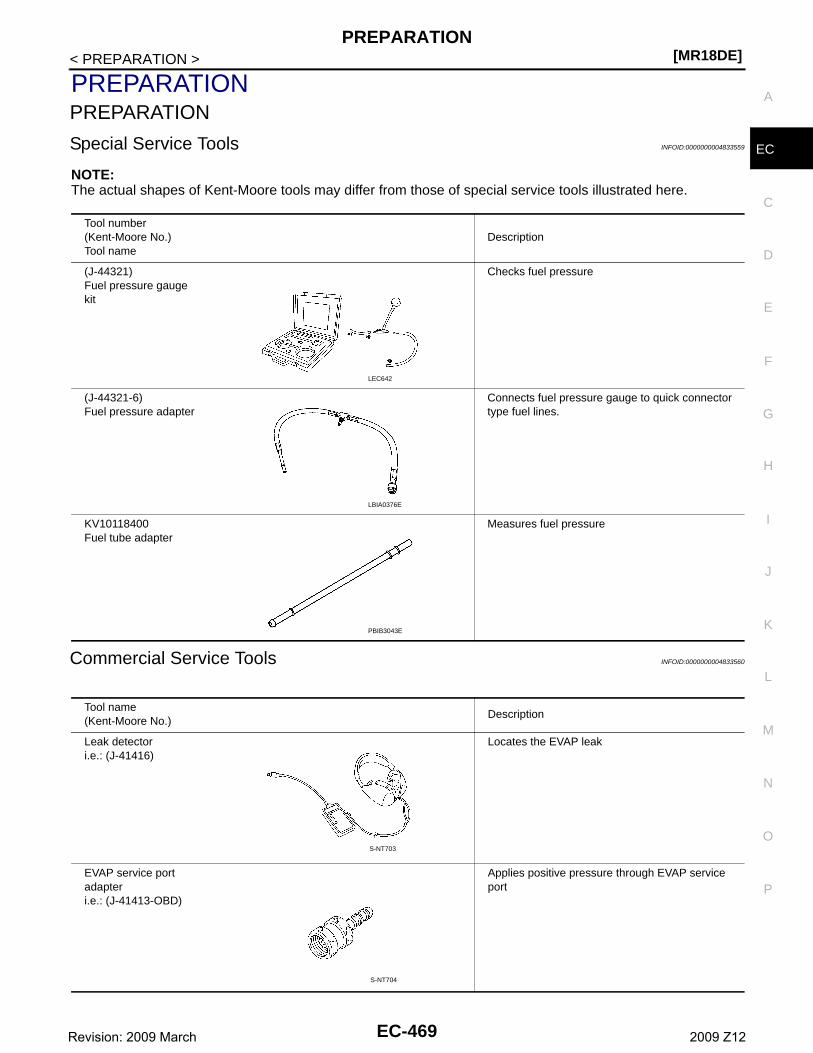
PREPARATION[MR18DE]
C
D
E
F
G
H
I
J
K
L
M
A
C
N
P
O
< PREPARATION >
E
PREPARATIONPREPARATION
Special Service Tools INFOID:0000000004833559
NOTE:The actual shapes of Kent-Moore tools may differ from those of special service tools illustrated here.
Commercial Service Tools INFOID:0000000004833560
Tool number(Kent-Moore No.)Tool name
Description
(J-44321)Fuel pressure gauge kit
Checks fuel pressure
(J-44321-6)Fuel pressure adapter
Connects fuel pressure gauge to quick connector type fuel lines.
KV10118400Fuel tube adapter
Measures fuel pressure
LEC642
LBIA0376E
PBIB3043E
Tool name(Kent-Moore No.)
Description
Leak detector i.e.: (J-41416)
Locates the EVAP leak
EVAP service port adapteri.e.: (J-41413-OBD)
Applies positive pressure through EVAP service port
S-NT703
S-NT704
EC-469Revision: 2009 March 2009 Z12
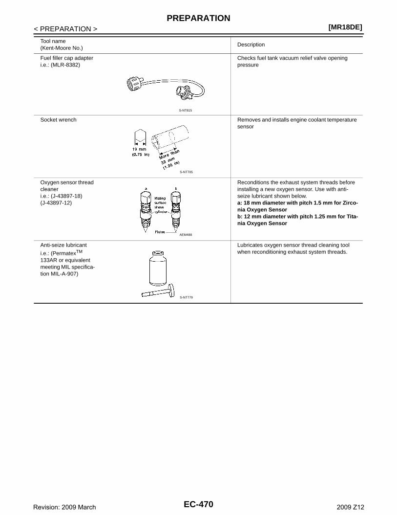
[MR18DE]PREPARATION
< PREPARATION >
Fuel filler cap adapteri.e.: (MLR-8382)
Checks fuel tank vacuum relief valve opening pressure
Socket wrench Removes and installs engine coolant temperature sensor
Oxygen sensor thread cleaneri.e.: (J-43897-18)(J-43897-12)
Reconditions the exhaust system threads before installing a new oxygen sensor. Use with anti-seize lubricant shown below.a: 18 mm diameter with pitch 1.5 mm for Zirco-nia Oxygen Sensorb: 12 mm diameter with pitch 1.25 mm for Tita-nia Oxygen Sensor
Anti-seize lubricant
i.e.: (PermatexTM 133AR or equivalent meeting MIL specifica-tion MIL-A-907)
Lubricates oxygen sensor thread cleaning tool when reconditioning exhaust system threads.
Tool name(Kent-Moore No.)
Description
S-NT815
S-NT705
AEM488
S-NT779
EC-470Revision: 2009 March 2009 Z12
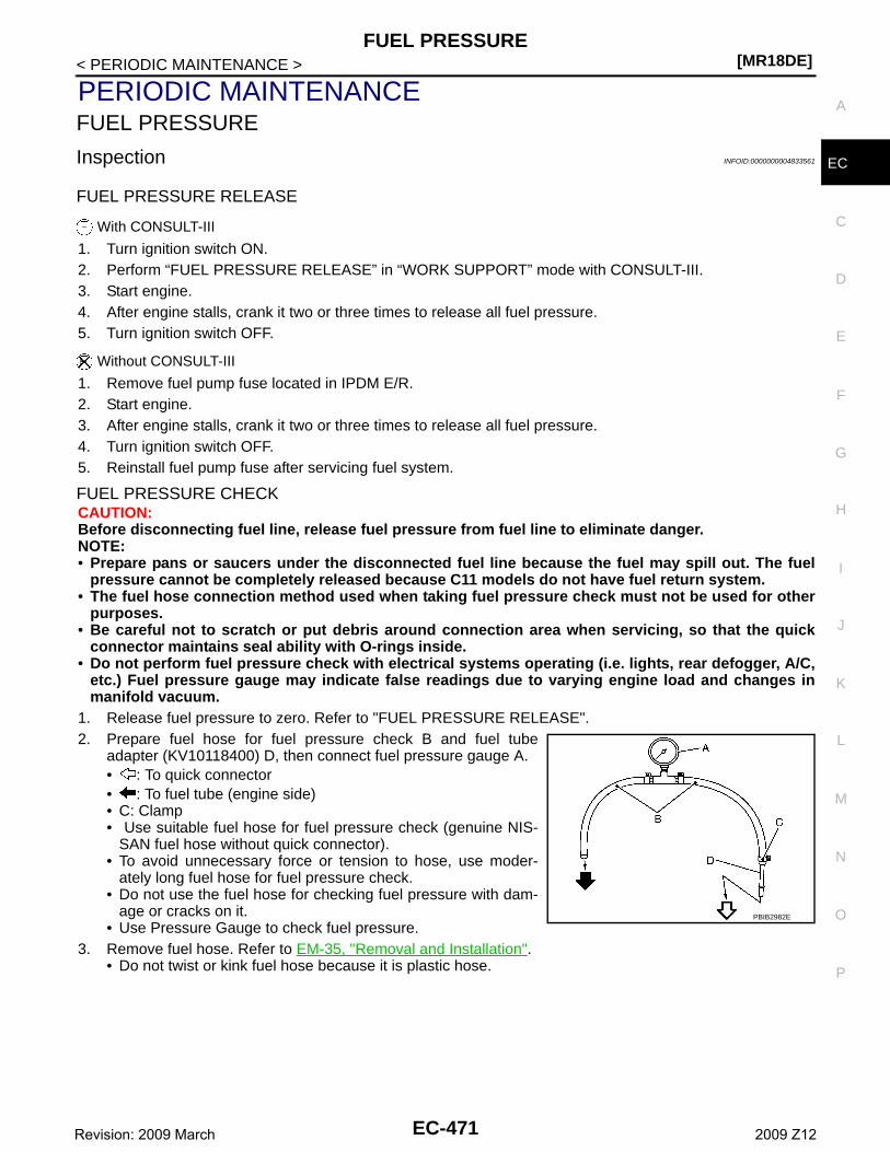
FUEL PRESSURE[MR18DE]
C
D
E
F
G
H
I
J
K
L
M
A
C
N
P
O
< PERIODIC MAINTENANCE >
E
PERIODIC MAINTENANCEFUEL PRESSURE
Inspection INFOID:0000000004833561
FUEL PRESSURE RELEASE
With CONSULT-III
1. Turn ignition switch ON.2. Perform “FUEL PRESSURE RELEASE” in “WORK SUPPORT” mode with CONSULT-III.3. Start engine.4. After engine stalls, crank it two or three times to release all fuel pressure.5. Turn ignition switch OFF.
Without CONSULT-III
1. Remove fuel pump fuse located in IPDM E/R.2. Start engine.3. After engine stalls, crank it two or three times to release all fuel pressure.4. Turn ignition switch OFF.5. Reinstall fuel pump fuse after servicing fuel system.
FUEL PRESSURE CHECKCAUTION:Before disconnecting fuel line, release fuel pressure from fuel line to eliminate danger.NOTE:• Prepare pans or saucers under the disconnected fuel line because the fuel may spill out. The fuel
pressure cannot be completely released because C11 models do not have fuel return system.• The fuel hose connection method used when taking fuel pressure check must not be used for other
purposes.• Be careful not to scratch or put debris around connection area when servicing, so that the quick
connector maintains seal ability with O-rings inside.• Do not perform fuel pressure check with electrical systems operating (i.e. lights, rear defogger, A/C,
etc.) Fuel pressure gauge may indicate false readings due to varying engine load and changes inmanifold vacuum.
1. Release fuel pressure to zero. Refer to "FUEL PRESSURE RELEASE".2. Prepare fuel hose for fuel pressure check B and fuel tube
adapter (KV10118400) D, then connect fuel pressure gauge A.• : To quick connector• : To fuel tube (engine side)• C: Clamp• Use suitable fuel hose for fuel pressure check (genuine NIS-
SAN fuel hose without quick connector).• To avoid unnecessary force or tension to hose, use moder-
ately long fuel hose for fuel pressure check.• Do not use the fuel hose for checking fuel pressure with dam-
age or cracks on it.• Use Pressure Gauge to check fuel pressure.
3. Remove fuel hose. Refer to EM-35, "Removal and Installation".• Do not twist or kink fuel hose because it is plastic hose.
PBIB2982E
EC-471Revision: 2009 March 2009 Z12
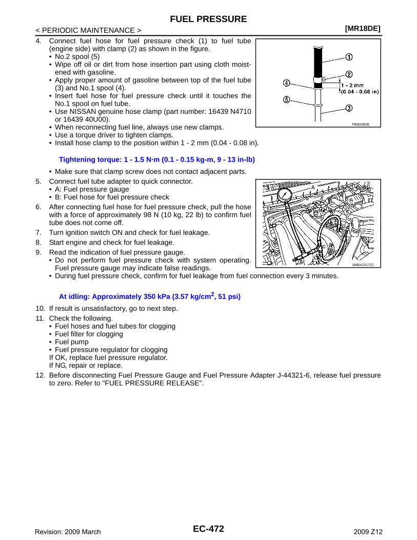
[MR18DE]FUEL PRESSURE
< PERIODIC MAINTENANCE >4. Connect fuel hose for fuel pressure check (1) to fuel tube
(engine side) with clamp (2) as shown in the figure.• No.2 spool (5)• Wipe off oil or dirt from hose insertion part using cloth moist-
ened with gasoline.• Apply proper amount of gasoline between top of the fuel tube
(3) and No.1 spool (4).• Insert fuel hose for fuel pressure check until it touches the
No.1 spool on fuel tube.• Use NISSAN genuine hose clamp (part number: 16439 N4710
or 16439 40U00).• When reconnecting fuel line, always use new clamps.• Use a torque driver to tighten clamps.• Install hose clamp to the position within 1 - 2 mm (0.04 - 0.08 in).
• Make sure that clamp screw does not contact adjacent parts.5. Connect fuel tube adapter to quick connector.
• A: Fuel pressure gauge• B: Fuel hose for fuel pressure check
6. After connecting fuel hose for fuel pressure check, pull the hosewith a force of approximately 98 N (10 kg, 22 lb) to confirm fueltube does not come off.
7. Turn ignition switch ON and check for fuel leakage.8. Start engine and check for fuel leakage.9. Read the indication of fuel pressure gauge.
• Do not perform fuel pressure check with system operating.Fuel pressure gauge may indicate false readings.
• During fuel pressure check, confirm for fuel leakage from fuel connection every 3 minutes.
10. If result is unsatisfactory, go to next step.11. Check the following.
• Fuel hoses and fuel tubes for clogging• Fuel filter for clogging• Fuel pump • Fuel pressure regulator for cloggingIf OK, replace fuel pressure regulator.If NG, repair or replace.
12. Before disconnecting Fuel Pressure Gauge and Fuel Pressure Adapter J-44321-6, release fuel pressureto zero. Refer to "FUEL PRESSURE RELEASE".
Tightening torque: 1 - 1.5 N·m (0.1 - 0.15 kg-m, 9 - 13 in-lb)
At idling: Approximately 350 kPa (3.57 kg/cm2, 51 psi)
PBIB2983E
JMBIA2317ZZ
EC-472Revision: 2009 March 2009 Z12
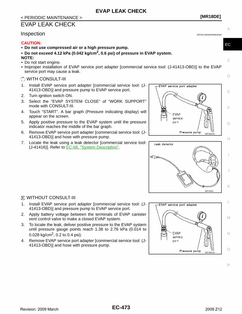
EVAP LEAK CHECK[MR18DE]
C
D
E
F
G
H
I
J
K
L
M
A
C
N
P
O
< PERIODIC MAINTENANCE >
E
EVAP LEAK CHECK
Inspection INFOID:0000000004833562
CAUTION:• Do not use compressed air or a high pressure pump.• Do not exceed 4.12 kPa (0.042 kg/cm2, 0.6 psi) of pressure in EVAP system.NOTE:• Do not start engine.• Improper installation of EVAP service port adapter [commercial service tool: (J-41413-OBD)] to the EVAP
service port may cause a leak.
WITH CONSULT-III1. Install EVAP service port adapter [commercial service tool: (J-
41413-OBD)] and pressure pump to EVAP service port.2. Turn ignition switch ON.3. Select the “EVAP SYSTEM CLOSE” of “WORK SUPPORT”
mode with CONSULT-III.4. Touch “START”. A bar graph (Pressure indicating display) will
appear on the screen.5. Apply positive pressure to the EVAP system until the pressure
indicator reaches the middle of the bar graph.6. Remove EVAP service port adapter [commercial service tool: (J-
41413-OBD)] and hose with pressure pump.7. Locate the leak using a leak detector [commercial service tool:
(J-41416)]. Refer to EC-68, "System Description".
WITHOUT CONSULT-III1. Install EVAP service port adapter [commercial service tool: (J-
41413-OBD)] and pressure pump to EVAP service port.2. Apply battery voltage between the terminals of EVAP canister
vent control valve to make a closed EVAP system.3. To locate the leak, deliver positive pressure to the EVAP system
until pressure gauge points reach 1.38 to 2.76 kPa (0.014 to0.028 kg/cm2, 0.2 to 0.4 psi).
4. Remove EVAP service port adapter [commercial service tool: (J-41413-OBD)] and hose with pressure pump.
SEF462UA
SEF200U
SEF462UA
EC-473Revision: 2009 March 2009 Z12
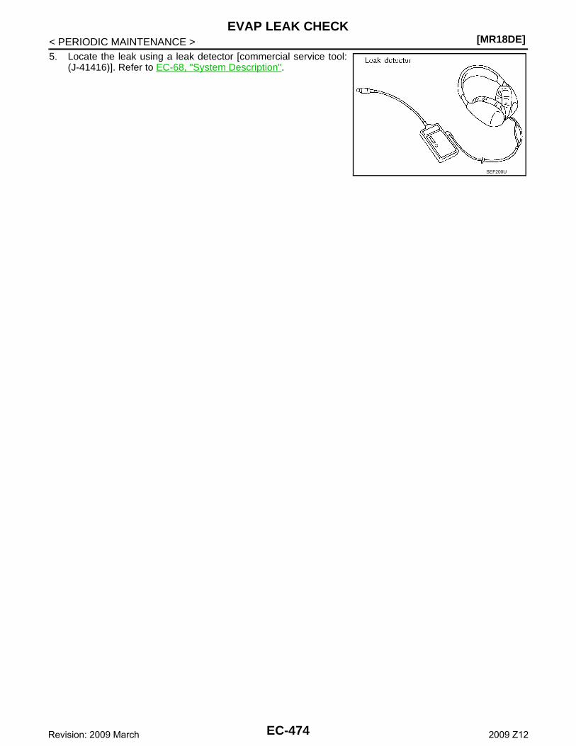
[MR18DE]EVAP LEAK CHECK
< PERIODIC MAINTENANCE >5. Locate the leak using a leak detector [commercial service tool:
(J-41416)]. Refer to EC-68, "System Description".
SEF200U
EC-474Revision: 2009 March 2009 Z12
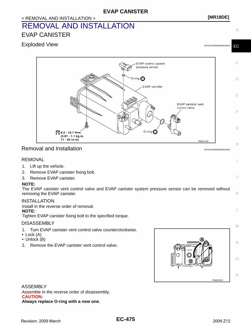
EVAP CANISTER[MR18DE]
C
D
E
F
G
H
I
J
K
L
M
A
C
N
P
O
< REMOVAL AND INSTALLATION >
E
REMOVAL AND INSTALLATIONEVAP CANISTER
Exploded View INFOID:0000000004833563
Removal and Installation INFOID:0000000004833564
REMOVAL1. Lift up the vehicle.2. Remove EVAP canister fixing bolt.3. Remove EVAP canister.NOTE:The EVAP canister vent control valve and EVAP canister system pressure sensor can be removed withoutremoving the EVAP canister.
INSTALLATIONInstall in the reverse order of removal.NOTE:Tighten EVAP canister fixing bolt to the specified torque.
DISASSEMBLY1. Turn EVAP canister vent control valve counterclockwise.• Lock (A)• Unlock (B)2. Remove the EVAP canister vent control valve.
ASSEMBLYAssemble in the reverse order of disassembly.CAUTION:Always replace O-ring with a new one.
PBIB1214E
PBIB3091E
EC-475Revision: 2009 March 2009 Z12
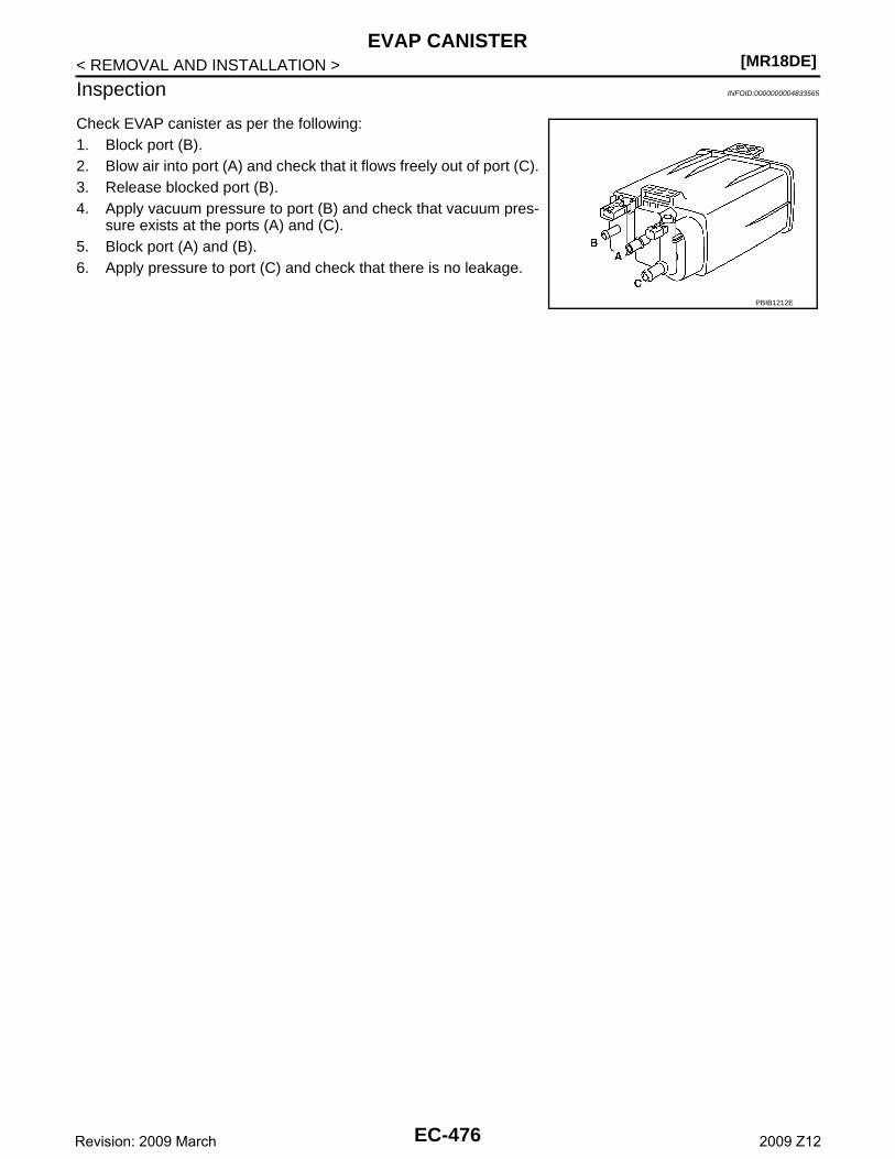
[MR18DE]EVAP CANISTER
< REMOVAL AND INSTALLATION >
Inspection INFOID:0000000004833565
Check EVAP canister as per the following:1. Block port (B).2. Blow air into port (A) and check that it flows freely out of port (C).3. Release blocked port (B).4. Apply vacuum pressure to port (B) and check that vacuum pres-
sure exists at the ports (A) and (C). 5. Block port (A) and (B).6. Apply pressure to port (C) and check that there is no leakage.
PBIB1212E
EC-476Revision: 2009 March 2009 Z12
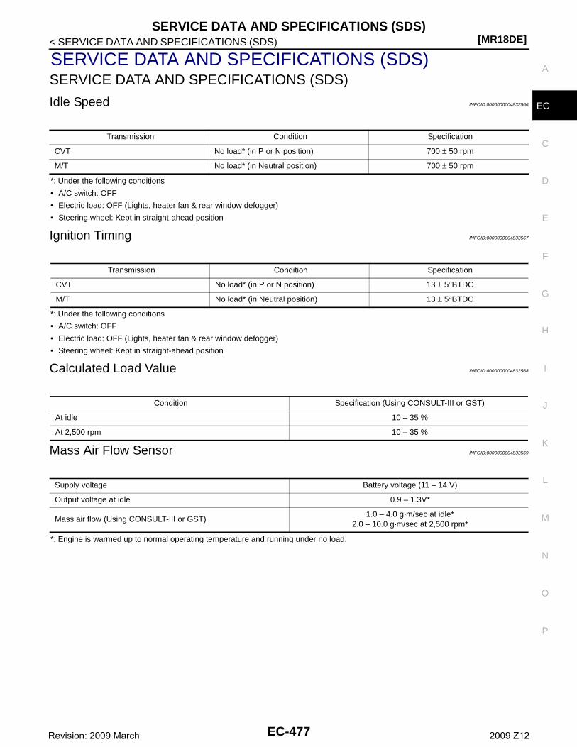
SERVICE DATA AND SPECIFICATIONS (SDS)[MR18DE]
C
D
E
F
G
H
I
J
K
L
M
A
C
N
P
O
< SERVICE DATA AND SPECIFICATIONS (SDS)
E
SERVICE DATA AND SPECIFICATIONS (SDS)SERVICE DATA AND SPECIFICATIONS (SDS)
Idle Speed INFOID:0000000004833566
*: Under the following conditions
• A/C switch: OFF
• Electric load: OFF (Lights, heater fan & rear window defogger)
• Steering wheel: Kept in straight-ahead position
Ignition Timing INFOID:0000000004833567
*: Under the following conditions
• A/C switch: OFF
• Electric load: OFF (Lights, heater fan & rear window defogger)
• Steering wheel: Kept in straight-ahead position
Calculated Load Value INFOID:0000000004833568
Mass Air Flow Sensor INFOID:0000000004833569
*: Engine is warmed up to normal operating temperature and running under no load.
Transmission Condition Specification
CVT No load* (in P or N position) 700 ± 50 rpm
M/T No load* (in Neutral position) 700 ± 50 rpm
Transmission Condition Specification
CVT No load* (in P or N position) 13 ± 5°BTDC
M/T No load* (in Neutral position) 13 ± 5°BTDC
Condition Specification (Using CONSULT-III or GST)
At idle 10 – 35 %
At 2,500 rpm 10 – 35 %
Supply voltage Battery voltage (11 – 14 V)
Output voltage at idle 0.9 – 1.3V*
Mass air flow (Using CONSULT-III or GST)1.0 – 4.0 g·m/sec at idle*
2.0 – 10.0 g·m/sec at 2,500 rpm*
EC-477Revision: 2009 March 2009 Z12


![[EC-CUBE関西ユーザグループ第1回] EC=CUBE紹介資料](https://img.pdfslide.net/doc/110x75/557ad3e9d8b42a0b188b5220/ec-cube1-eccube.jpg)